maurizio piazza , paolo zanon , cristiano loss · massive cross-laminated timber panels ... to...
TRANSCRIPT

G. Manfredi, M. Dolce (eds), The state of Earthquake Engineering Research in Italy: the ReLUIS-DPC 2010-2013 Project, 143-172, doi: 10.14599/r101304, © 2015 Doppiavoce, Napoli, Italy
TIMBER STRUCTURES
Maurizio Piazza a, Paolo Zanon b, Cristiano Loss c
University of Trento, Department of Civil, Environmental and Mechanical Engineering, Trento, Italy, a [email protected], b [email protected], c [email protected]
1 INTRODUCTION
Wood is a building material that can be used for different applications, ranging from its implementation as structural component to interior design. In particular, if we refer to the residential market in Italy, a non-negligible percentage of new buildings is currently being constructed using a timber structure. Modern timber construction systems allow the building of a structure in a very simple and competitive way, especially in relation to the time required for construction operations. Wooden buildings, traditionally associated with the idea of the mono- or multi-family single dwelling, can now be associated with the idea of a residential complex, with a notable area in plan and with a remarkable number of storeys. This is a new and more general use of wood as structural material, also thanks to modern assembly techniques and to the presence on the market of highly engineered components and elements (CLT panels, GLT glulam elements, LVL panels, other wood-based materials). Wood is considered to be a material particularly suitable for earthquake-resistant structures, due to its low density, with a resistance to mass ratio similar to that of steel, and much more effective than other traditional materials, i.e. concrete or masonry. In short, this means that the stresses acting on a timber building in the event of an earthquake, being proportional to the mass of the building itself, are much lower. On the other hand, timber structures are generally more flexible than similar structures built with reinforced concrete or masonry: this proves to be a further advantage, as a flexible structure is typically less 'sensitive' to the consequences of seismic excitation. However, timber has some critical characteristics related to the intrinsic brittleness of the material, at least in the case of tensile and bending stresses. Nevertheless, it should be noted that the timber building is never a ‘monolithic’ frame, but it is formed by several elements (beams, walls, floors), joined together through mechanical connections. Those connections, if correctly designed, can give a very positive contribution to the overall behaviour of the building, thanks to the plastic (or, generally, non-elastic) deformation of the metallic elements and to the friction between the contact surfaces, allowing for dissipation of the energy released during an earthquake. This was proved both by recent experimental research carried out on modern timber buildings, and by the survey done on existing structures after recent earthquakes. Many timber buildings, in Japan and China, withstood several earthquakes during centuries of life. A famous example can be cited, among many others: the Pagoda of Sakyamuni, in the county of Yingxian (Shanxi province), with more than 950 years of life, 67 meters high, entirely assembled with carpentry joints. Referring to modern timber buildings, the most commonly used construction typologies involve the utilization of prefabricated wood panels, both light-timber framed walls or massive cross-laminated timber panels (CLT), assembled at each storey (the so-called platform frame construction process). In these systems, the prefabricated elements can

M. Piazza, P. Zanon, C. Loss
144
simultaneously perform as structural elements and as elements of the building envelope. The timber walls and floors can easily be prefabricated at the factory, and then assembled on site by means of steel mechanical connections. With regard to light-timber-frame houses, they are very popular especially in the English-speaking world, primarily North America, New Zealand and Northern Europe. The wood timber-frame walls are based on equally spaced vertical studs and on the horizontal bottom and top plate: this ‘wood frame’ is closed with thin wood-based panels (OSB, plywood etc.), connected to timber elements using simple connections, like nails, staples or screws. The wood-based panels are used both as the bracing system in the plane of the wall and as closing system of the frame. The construction system resorting to the use of solid wood panels, typically cross-laminated timber panels (CLT), was recently introduced in Europe, but recently it was also adopted in other countries, i.e. Canada and the United States. The prefabricated planar elements are used both as floor and wall structures: the CLT elements are obtained by superposition of crossed arranged layers of wood boards, joined together by gluing. Timber buildings produced with one of these construction systems generally have remarkable seismic-resistant characteristics, when properly designed and assembled. In addition, possible post-earthquake interventions are highly simplified and quite easy as they consist in replacing the damaged parts of the connections. The aim of the work done is to provide the basis for developing guidelines to be used for the design of earthquake-resistant timber buildings. The contents are mainly oriented to the designers, to Companies and, generally, to professionals who are actively involved in the construction process. Due to lack of space, references are inserted in the text to specific documents and papers produced within the framework of RELUIS 2010-2013 research program. Some observations are also reported, which can be used as background for modifications, clarifications or, simply, amendments to improve the Italian 'Technical Standards for Construction', Chapter 7 (CS.LL.PP., 2008), and Eurocode 8, Chapter 8 (CEN, 2004).
2 BACKGROUND AND MOTIVATION
The Italian market covering the residential construction area has multiplied by five the number of houses built with timber structure systems, between the beginning of 2006 and the end of 2010. From a recent Italian survey conducted on behalf of the ‘FederlegnoArredo’, in short FLA (Gardino, 2011), it is clear that timber buildings will further increase by 50% over the next 5 years starting from the data recorded in 2010. The main construction systems used to build houses are typically based on panel construction elements, whether they are made of light weight wood frame panels or cross-laminated timber panels. In these systems, structural panels can simultaneously develop the bearing function and be considered as building envelope. Such systems can be easily built using prefabricated and modular elements, produced in factory, and subsequently joined on site using mechanical connections. The simplicity of installation of timber construction systems, in addition to their sustainability and biocompatibility, makes this solution increasingly competitive for buildings if compared to buildings assembled using traditional materials. Recent studies conducted by the National Institute of Geophysics and Volcanology (NIGV) confirmed that Italy is a country exposed to a medium-high seismic hazard. The NIGV has implemented the seismic hazard map for our area, which can be used to evaluate the probability of occurrence of an earthquake of a given intensity as function of the time range
Timber Structures
145
and the local geographical coordinates. The problem of seismic risk mitigation, namely the reduction of adverse consequences of earthquakes on people, is the main problem of earthquake engineering, as well as one of the worst problems a national civil protection system has to deal with. The Italian construction regulations in response to this need have always been affected by updates, especially in the last decade, in order to incorporate all of the latest developments in the seismic design field. However, this updating process has not always been accompanied by an adequate and effective response by designers. Sometimes, the seismic design procedures have been proved excessively exposed to the opinion and decision of the single designer. This research aims at studying several aspects about the design of earthquake-resistant structures for residential use. The main objective of this research program is to provide some rules for the design of new timber buildings in seismic areas. Design rules, accompanied by a series of design examples to use when calculating earthquake-resistant timber structures, are the target product of the research. The objective of these rules is to guide designers in the realization of timber houses, taking into account structural and technical problems. Such document aims at providing design procedures to be applied complying with the directives of recent seismic standards, Eurocode 8 (CEN, 2004) and the Italian Technical Standards for Construction, NTC 2008, (CS.LL.PP, 2008), integrated with suggestions for the design of cases not covered by those standards. Dimensioning models from recent developments, presented in documents of proven reliability, as well as advanced knowledge and experience gained in the international context, will be inserted within this document. This document can be considered as the first attempt towards the establishment of guidelines for the design of timber buildings.
3 RESEARCH STRUCTURE
The seismic performance of timber buildings is generally adequate thanks to their light weight and structural uniformity. In areas of high seismic risk, such as Japan and China, there are ancient buildings that prove the effectiveness of construction techniques adopted to withstand earthquakes. New timber buildings are built with various techniques and construction typologies. Many systems have evolved, with the progression from traditional (carpentry joints) to modern methods (engineered joints; e.g. mechanical connections or glued-in metallic joints) for building element assembly and from the use of solid wood elements to the use of engineered wood elements. Some of the house building technologies and construction systems in use in Europe were developed in areas where the occurrence of earthquakes is negligible. However, these construction systems are often employed with excessive optimism in Italy and even in areas of high seismic risk. In this work we intend to define a strategy for the design of earthquake-resistant timber buildings for residential use. Wood is a building material that offers high load capacities in relation to its weight. The strength characteristics of wood are influenced by its anisotropy and its rheological behaviour. The strength and stiffness of a timber element varies with any defects present and with the orientation of the applied load with respect to the fibres. The stress-strain curves (σ-ε) of a timber element show a behaviour that is markedly fragile, except for the elements compressed perpendicularly to the grain. Failure mechanisms due to bending or shear are brittle and must therefore be avoided in seismic zones. To obtain a ductile response of the structure, the design of the connections must respect the Capacity Design rules (CD rules), which ensure that the connections are the weakest links between timber elements.

M. Piazza, P. Zanon, C. Loss
146
CONFIGURATION OF THE CONNECTION (a) Glued joints (A=12500 mm2) (b) Split-ring (d=100 mm) (c) Double sided toothed-plate (d=62 mm) (d) Dowel (d=14 mm) (e) Bolt (d=14 mm) (f) Punched plate (A=100x100 mm2) (g) Nail (d=4.4 mm)
Figure 1. Experimental load-slip curves for joints in tension parallel to the grain (modified from Racher, 1995).
The ductility of the system is thus achieved through the correct selection and the careful design of connections. Figure 1 shows the monotonic load-slip response (F-u) and the level of ductility obtained for a series of timber connections. The dissipative capacity of connections, under repeated loading, is related to the strength of the materials and to the geometric configuration of the joints. We simply show that only certain types of connection give the desired ductility level and hysteretic behaviour. The connections normally used in modern timber constructions are elements or metal devices that can transmit forces among structural elements. A set of timber structures designed to ensure ductile behaviour, used in the European housing construction market, is shown in Figure 2. (a) (b) (c)
Figure 2. Timber house systems: (a) timber frame panels; (b) cross-laminated timber panels; (c) log-house.
If well designed, the construction systems of Figure 2 provide the desirable ductile behaviour. These first considerations highlight the importance of studying the dynamic response of

Timber Structures
147
different timber structure systems, with various types of connection and installation. The research was divided into tasks with specific objectives for the various structural types. The study of each structural type covers some specific aspects (Table 1): (i) the research on the state-of-the-art construction types investigated, (ii) experimental tests and (iii) non-linear static and dynamic analyses. For each structural type, we intend to develop a set of case studies on full-scale buildings with available static or dynamic tests on the elements or the whole structure. For each specific structural type we define the evaluation criteria for structure element strength and deformation capacity, as well as the dynamic characteristics needed to define the seismic response (damping, dissipative capacity and deformed shape of the structure), also related to the structural analysis method adopted. Laboratory tests to define the mechanical properties of the materials, their use within buildings and their installation are expected from all Research Units (RU). We also include tests on some structural elements for each structural type. Some tests were carried out at the university laboratories involved in the research project. The results of this work are also supported by the experience gained during the post-earthquake reconstruction in the L’Aquila area in Italy. Some experimental data are available from the tests performed during the reconstruction phase and kindly offered us by the builders.
Table 1. Research topics and main activity of each Research Unit.
Research Unit
Research Topic University of Project leader
RU1 General aspects of timber construction systems
Trento Prof. M. Piazza
RU2 Cross-laminated timber panel systems Brescia Prof. E. Giuriani
RU3 Solid wood wall systems Naples Prof. B. Calderoni
RU4 Timber frame construction systems Trieste Prof. N. Gattesco
RU5 Timber frame panel construction systems Udine Prof. A. Gubana
RU6 Development of numerical models for timber systems
Sassari Prof. M. Fragiacomo
In conclusion, this work has been organized so as to develop a structured and consistent tool, experimentally and numerically validated, that allows us to define some rules of calculation and experimental verification for timber structures, with particular attention to their seismic behaviour. The research has been divided into tasks, with specific objectives for each construction system. However, we intend to develop a series of design rules for each of the timber construction systems. Some Research Units have been involved in laboratory work, performing full-scale tests on the structural timber elements currently employed in European construction systems. Other Units have worked on the development of numerical models that describe and reproduce the load-deformation curves found experimentally and that simulate the energy dissipation capacity of the various structure types. The main results obtained by the Research Units during this three-year project will be presented in the following Sections.

M. Piazza, P. Zanon, C. Loss
148
4 MAIN RESULTS
Research Unit 1 (RU1) was responsible for summarizing the current state-of-the-art regarding the design and construction of timber buildings in Italy, also considering the recent post-earthquake reconstruction work at L’Aquila (Italy). The RU of Trento coordinates and guides all the other Research Units activities. The Unit has held discussions with researchers and has promoted the liaison with the Italian producers involved in the Project. The acquisition of all the results obtained from the individual Units, whether obtained experimentally or by numerical simulation, complete the work carried out during the three-year research project. Each Research Unit has specifically investigated some peculiar aspects of earthquake-resistant buildings, here intended as construction systems designed to ensure suitable performance in relation to the seismic intensity level. The current structural systems used to build timber buildings we make reference to in this task have been classified as follows: cross-laminated timber panel construction systems (Figure 3) and light wood frame construction systems (Figure 4). The research activity of RU Trento was focused on an experimental campaign on full scale specimens of timber walls for their mechanical characterization, in terms of stiffness and resistance (Figure 5), whose main results can be found in (Piazza et al., 2013). Research results and other useful design instructions were included within each annual technical report, in order to make it as clear as possible to the designers and engineers involved in timber engineering. The research activity of RU Brescia has focused its research on three main topics: the drafting of guidelines for the design of CLT timber buildings with design case study, a theoretical and numerical study on the influence of floor diaphragm stiffness on the distribution of the seismic action among the shear walls, and theoretical and experimental studies on Platform Frame walls. The research work of the Unit of Brescia has been devoted to investigating the deformability influence of diaphragms (due to the connections among the elements) on the distribution of the seismic action among the resisting walls. The work has been developed by means of numerical analyses as well as analytical approaches. The results show that, for both inclined screws and nails, the forces of a statically undetermined distribution tends to the solution of a diaphragm on simply supported beams, independently from the distance and the diameter of the connectors employed (Figure 6). The Brescia RU has worked on the evaluation of the ductility and of the dissipative behaviour of timber Platform Frame walls (which basically consist of particleboard sheathing nailed onto a glulam timber framework). The study aims at assessing the behaviour factor q used when the Capacity Design criterion is adopted for the design process. Firstly, the attention was focused on the evaluation of the ductility and dissipation capacity of the local connections (sheathing-to-framing joints, hold-down and shear angle brackets); secondly, the experimental campaign focused on the full-scale shear wall behaviour. Concerning the local behaviour of the connections, the experimental results pointed out that, depending on the type of nails (smooth or ring), the initial stiffness and ultimate strength can assume different values: smooth nails guarantee higher initial stiffness, whereas ring nails, by enhancing the axial-withdrawal capacity, guarantee higher ultimate capacity (Figure 7). So, the surface feature of the nail may be a crucial parameter, which in turn may affect shear wall behaviour.

Timber Structures
149
Figure 3. Building constructed using timber frame panel technology: (I) axonometric view of the structure; (II) wall configuration; (III) individual shear wall element; (IV) mechanical connections to
prevent lifting and overturning of shear wall elements; (V) vertical and horizontal section of the wall and typical connection between frame and sheathing panels (Loss et al. 2013a).

M. Piazza, P. Zanon, C. Loss
150
Figure 4. Building constructed using cross laminated timber panel technology: (I) axonometric view of the structure; (II) wall configuration; (III) individual shear wall element; (IV) mechanical connections to
prevent lifting and overturning of shear wall elements; (V) vertical and horizontal section of the wall (Loss et al. 2013a).

Timber Structures
151
(a)
(b)
(c)
Figure 5. Test on log-house walls (a), timber frame walls (b) and cross laminated timber (CLT) walls.

M. Piazza, P. Zanon, C. Loss
152
Support infinitely stiff , only
bending stiffnessSupports infinitely stiff, shear,
bending stiffness, shear modulus
2/3pl 2/3pl 2/3pl
Impalcato rigido su appoggi deformabili
pl/2 pl pl/2
Deformabile a taglio
(3/8pl 10/8pl 3/8pl
Deformabile a sola flessione
(b
Infinite stiff both in bending and in shear
Bending deformabiity Shear deformability
Infinite bending and shear stiffness
Figure 6. Distribution of the shear actions among shear walls.
Figure 7. Experimental results of cyclic and monotonic tests on nailed connections. load vs. displacement curves for a single fastener: smooth nails (a), ring nails NRa (b) and NRb (c) (Germano et al., 2012;
Germano et al., 2013b). The experimental results were compared to the maximum strength and stiffness estimated according to the main European standards, such as EN 1995, DIN 1052 and CNR-DT 206. The Standards overestimate the strength of smooth nails by about 13% without taking into account the “rope effect”, which for EN 1995 and CNR-DT206 may be up to 15% of the connection resistance calculated according to Johansen's theory, by considering the formation of two plastic hinges in the nail shank, as experimentally confirmed. For ring nails,

Timber Structures
153
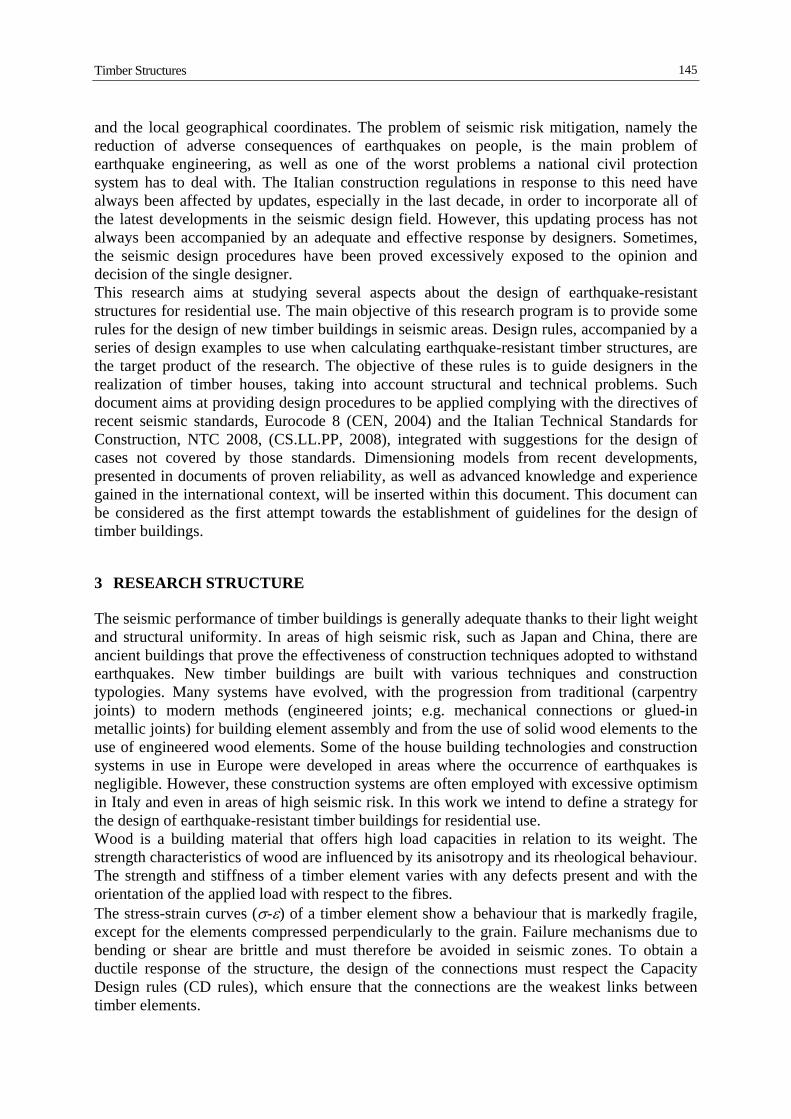
characterized by one plastic hinge, an underestimation of more than 30% may be observed, which points out their important withdrawal capacity. Regarding stiffness, the Standards' formulation provides an initial stiffness value in good agreement with the experimental results for smooth and NRb ring nails with a difference ranging between 18 and 32% depending on the code considered. The experimental stiffness of NRa nails resulted 75% lower than the calculated one, because the Standards do not consider the effect of shank surface which may create an initial clearance in the timber connected elements. Furthermore, on the basis of the test results, according to the requirements of Eurocode 8 and Italian Standard for dissipative zones, only smooth nails and ring nails with a limited surface roughness of the shank (type NRb in Figure 7) can be employed for structures of High Ductility Class (DCH). NRa nails should be used for Medium Ductility Class (DCM) only, since they showed a strength reduction greater than 20% for a displacement equal to 6 times the yield displacement vy. A test bench was designed to study a full-scale shear wall (Figure 8), which was tested under cyclic reverse loading displacement of increasing amplitude. The 2500x2500 mm walls consisted of a timber frame with 5 glulam studs hinged to the upper and the bottom rail. The frames were sheathed on both sides with two vertically oriented 1250x2500 mm particleboard panels (P5 type according to EN 312 having a thickness of 18 mm). The panels were fastened to the frame by NRb ring nails with a constant spacing of 100 mm along the edges of the particleboard panels and 150 mm along the inner stud.
Figure 8. Light timber frame walls tested by the Brescia RU (Germano et al., 2013a,b). Two different levels of vertical load were applied. The first shear wall (SW-0) was tested without a vertical load, while the second wall (SW-100) was also subjected to a vertical load of 100 kN (equivalent to 40 kN/m), which may represent the gravity load carried by a ground floor wall of a three-storey building. The cyclic behaviour of the shear walls was not affected by the vertical load, since hold-downs and shear brackets, which were designed with an adequate overstrength factor (equal to 1.5), efficiently restrained the uplift and the sliding of the wall (Figure 9a). The shear walls collapse at about 2.5% of drift due to low cycle fatigue fracture of the nail connection between sheathing panel and timber frame. High strength steel nails, commonly used in wood frame structures, are characterized by low ultimate tensile strain (εsu<3%) resulting in a limited capability to dissipate energy for high drift values and a large number of cycles.
M. Piazza, P. Zanon, C. Loss
154
-100
-75
-50
-25
0
25
50
75
100
-80 -60 -40 -20 0 20 40 60 80
Shea
r lo
ad, V
[kN
]
Shear wall horizontal displacement [mm]
Angle brackets
Hold-down
Tot. Horiz. Disp
Nails
DAB
DH
DN
SW-100
Angle brackets (DAB)
Hold-down (DH)
Tot. Horiz. Disp. (Dtot)
Nails (DN=Dtot-DAB-DH)
Figure 9. (a) Experimental results on Platform frame wall: shear action against the inter-story drift; (b) contribution of each type of connection on the horizontal displacement of the SW-100 shear wall
(Germano et al., 2013a,b).
-100
-80
-60
-40
-20
0
20
40
60
80
100
-70 -60 -50 -40 -30 -20 -10 0 10 20 30 40 50 60 70
Car
ico
oriz
zont
ale
[kN
]
Scorrimento corrente superiore [mm]
p
Parete B
Modello Analitico
Modello Numerico
Top rail displacement [mm]
Hor
izon
tal L
ater
al lo
ad [k
N]
Experimental test
Analytical model
Numerical model
Figure 10. (a) Energy dissipated by each connection (Germano et al., 2013a,b); (b) comparison between experimental tests and analytical/numerical ones (Germano et al., 2013c).
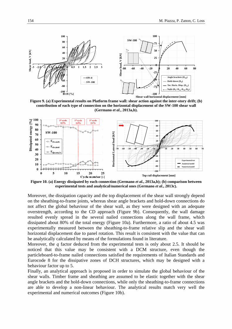
Moreover, the dissipation capacity and the top displacement of the shear wall strongly depend on the sheathing-to-frame joints, whereas shear angle brackets and hold-down connections do not affect the global behaviour of the shear wall, as they were designed with an adequate overstrength, according to the CD approach (Figure 9b). Consequently, the wall damage resulted evenly spread in the several nailed connections along the wall frame, which dissipated about 80% of the total energy (Figure 10a). Furthermore, a ratio of about 4.5 was experimentally measured between the sheathing-to-frame relative slip and the shear wall horizontal displacement due to panel rotation. This result is consistent with the value that can be analytically calculated by means of the formulations found in literature. Moreover, the q factor deduced from the experimental tests is only about 2.5. It should be noticed that this value may be consistent with a DCM structure, even though the particleboard-to-frame nailed connections satisfied the requirements of Italian Standards and Eurocode 8 for the dissipative zones of DCH structures, which may be designed with a behaviour factor up to 5. Finally, an analytical approach is proposed in order to simulate the global behaviour of the shear walls. Timber frame and sheathing are assumed to be elastic together with the shear angle brackets and the hold-down connections, while only the sheathing-to-frame connections are able to develop a non-linear behaviour. The analytical results match very well the experimental and numerical outcomes (Figure 10b).

Timber Structures
155
Numerical and theoretical studies were developed by the Brescia RU concerning the role of the connections between XLAM panels in the seismic response of structural systems. Two characteristic layouts of the walls were studied: (a) multi-storey walls made with overlapping single-storey XLAM panels (Figure 11a); (b) multi-storey walls with coupling action between adjacent XLAM panels (Figure 11b). Non-linear analyses pointed out that while in structures with overlapped XLAM walls the displacement demand is generally lower than deformation capability guaranteed by the nailed connections, in the case of the coupled walls the ductility both of the connections between adjacent panels and of the hold-down connections at the wall base is not sufficiently adequate to guarantee structure deformation capacity greater than the displacement demand. As a result, for the design of XLAM buildings according to the CD approach, a behaviour factor not greater than 1.5 is strongly recommended (Metelli et al., 2012). (a) (b)
Figure 11. Overlapped walls (a) and coupled walls (b) (Metelli et al., 2012).
The Research Unit of Naples has worked to develop simplified models for the design and verification of buildings built with cross-laminated timber panel construction systems. These models are based on the outcomes obtained in preceding years, concerning the calibration of complex numerical finite element models, in which panels and mechanical connections at various floors and at the base, and their non-linear behaviour, have been properly taken into account. In such models, plasticity is concentrated in the contact and anchoring area of the panels. From the results obtained using complex models, a simple mechanical model has been defined which considers the non-linear behaviour of the panels concentrated in sections close to the adjacent planes and at the foundation. Specifically, starting from the results obtained with the complex FEM model, the Research Unit of Naples proceeded to:
I. define buckling verification criteria for the CLT panels used within the load-bearing
walls; II. calibrate a simplified equivalent frame model for structural analysis.
To determine the ultimate bending moment of the panel-to-connections system, researchers started from the analogy of a common reinforced concrete section, in which the reinforced elements are formed by mechanical connections, while compressive strength is ensured by the panel-to-panel (and panel-to-foundation) contact area. According to this hypothesis, the compressive strength of the wood to be used is the one perpendicular to the fibres. The procedure for the determination of the resistance bending moment firstly considers the connection systems and the bond of wood in the compression orthogonal to the fibres. In this work, a parabola-rectangle diagram of wood is assumed, while for connection systems a

M. Piazza, P. Zanon, C. Loss
156
stress-strain relationship of steel or connectors can be assumed, depending on the hierarchy rules employed: the plasticization of the steel plate or the ‘yield’ of connectors. Then, the position of the neutral axis can be determined using an iterative procedure, based on translation and rotation equilibrium equations. The ultimate bending moment is the one that balances internal and external forces. In the definition of the ultimate bending moment and in the construction of the M-N domain of the section (Figure 12), the ultimate strain of the wood in the direction orthogonal to fibres has significant influence (common values up to 10% and over). The analyses performed confirmed that the higher the value of the ultimate compression strain, the higher the ultimate bending moment and the curvature ductility of the section. In this work, an ultimate strain between 1% and 5% has been considered. (a) (b)
0,0
50,0
100,0
150,0
200,0
250,0
300,0
350,0
-1000-900 -800 -700 -600 -500 -400 -300 -200 -100 0 100 200 300 400 500 600 700 800
N[KN]
M [KNm]
Figure 12. (a) Analytical model of the cross-section; (b) M-N Domain.
In order to validate the procedure, the ultimate bending moment value obtained from the simplified model was compared with the one provided by the FEM model with implemented system-to-panels connections at the collapse state. In all the recorded cases, the deviation of the results is less than 5%. The analytical M-N domain is preparatory to the definition of a simplified equivalent frame model with concentrated plasticity, which can be used to perform non-linear analyses. The analyses performed with the FEM model have highlighted the lack of efficiency offered by lintels in the coupling of the piers with respect to seismic actions. Thus, the most suitable computational model of the wall to be used in design and verification is the one with full cantilever beam connected at each floor by pendulums. Therefore, even in the definition of the simplified model, the equivalent frame model has been implemented with macro-elements connected with pendulums: the uprights elements follow the centreline of piers while pendulums follow the centreline of lintels. A first set of non-linear static analyses were performed with this model, using flexural plastic hinges in upright elements (with known axial force) and with ultimate bending moment estimated with the procedure described earlier, and neglecting the behaviour of mechanical connections. Comparison between the pushover curves extracted from the refined FEM model and the equivalent frame model has demonstrated that the latter behaves with higher elastic stiffness. Indeed, in the first case the intrinsic deformability of connections (hold-downs and steel brackets) has been considered negligible. On the other hand, a good agreement between the ultimate strength estimated by the simplified and refined model confirms the reliability of the

Timber Structures
157
method used for the calculation of the ultimate bending moment. However, this shows that it is better to take into account the behaviour of mechanical connections in the evaluation of the final response of the structure. In the simplified model we have introduced several springs with an equivalent elastic stiffness evaluated from the force-displacement curve of the mechanical connections used. In particular, we have introduced a rotational spring (kφ) to model the flexural stiffness of the panel-to-connections systems (evaluated considering bending moment and axial force action), and linear springs (kt) which simulate the shear stiffness of connections. Comparison between the curves obtained from the new equivalent-frame model (with springs) and the refined FEM model highlights a good approximation in the evaluation of the global deformation of walls. Within the framework of the simplified model, the next step will be to define a reduced elastic stiffness to be assigned to the vertical structural elements (wooden piers), which takes into account the intrinsic deformation of connections. The research work of RU Trieste has concerned the study of the dynamic behaviour of multi-storey wooden buildings (Figure 13). (a) (b)
Figure 13. Timber frame panel systems (a) and timber frame systems (b).
In this structural type, the walls are made with wood-based panels nailed onto a framework of wooden studs and joists (Figure 14). The walls, which have the task of bracing the structure, are connected to a timber frame made with continuous columns and beams, with the task of withstanding the vertical loads. (a) (b)
Figure 14. Nailed connections between shear walls and posts: simple shear wall panels (a) and sandwich
panels (b).
Some experimental tests were performed on two wooden walls 2105x2870 mm in dimension, with the purpose of assessing the effective capacity and deformability in the plane. The lateral studs have a 160x200 mm section in one sample and a 140x160 mm section in the other. The panels of wood particles, arranged on both sides of the frame, were fixed with 2.8/70 nails, arranged at a distance of 50 mm on the outer studs and the top/bottom joists and at a distance

M. Piazza, P. Zanon, C. Loss
158
of 100 mm on the interior studs; the thickness of the panels is 20 mm for the first sample and 15 mm for the other. The tests were conducted under displacement control and the samples were subjected to a sequence of symmetrical cycles, with increase of the maximum horizontal displacement imposed at the top of the wall (cyclic shear test). The experimental results have shown that the resistance is slightly higher in the thicker wall (128 kN), compared to the thinner one (119 kN). On the contrary, the stiffness in the second sample was greater (5.5 kN/mm) than that of the first one (4.2 kN/mm). The results of the two tests were compared with those of the five cyclic shear tests conducted in the course of the project to highlight the differences in behaviour and response in function of the different characteristics of the samples (different sizes, different spacing among the nails connecting the panels to the frame, different application of the hold-down, different type of connection at the wall base, presence of openings, etc.). All tests have identified some of the main shortcomings of the system in terms of response to seismic actions. In particular, the influence of the following aspects was evaluated:
I. positioning of the connections hold-down: the placement above the panels causes shear failure of the latter in the area close to the hold-down; instead, by fixing the hold-downs directly to the studs of the frame, the nailing connection determines the crisis of the wall;
II. restraints at the base of the wall: the shear slip at the bottom of the wall, which is negligible in the case of connections to ground via threaded rods, becomes appreciable in the case of connections with nailed steel angles;
III. size of the wooden elements of the framework: the shear resistance of the wall increases by very little when passing from elements with 140x160 mm cross section to 160x200 mm elements;
IV. spacing of the nails connecting the panels to the framework: when halving the spacing of nails, a slight increase in the stiffness of the wall and a considerable increase in resistance (almost proportional to the number of the nails) is observed;
V. panel material and thickness: very small differences in terms of stiffness and strength were noted between particle boards and OSB panels;
VI. perforated walls: the presence of window openings in the wall, if not too extensive, do not appreciably affect the strength of the wall, whereas stiffness is significantly reduced in comparison to walls without openings.
On the basis of the experimental results (Figure 15), a theoretical study was carried out to define an analytical method that allows to correctly estimate the stiffness of the walls to be considered in the evaluation of the horizontal actions shared among the resisting elements (shear walls). A simplified model of the walls has been proposed using two-dimensional elements or extensional diagonal springs, whose stiffness characteristics are measured taking into account the contributions of the shear and flexural deformability of the wall, the deformability of the connections of the wall to the base and to the columns and of the panel to the framing (Figure 16). In order to consider the deformability of the base connections of the columns (strong angles or hold-down), the use of tensile extensional springs placed at the bottom of the frame was suggested. These theoretical studies were also extended to cases of walls made with multiple segments and walls with openings, proposing simplified procedures.

Timber Structures
159
Figure 15. Experimental shear tests on timber shear walls (Gattesco and Franceschinis, 2012).
δc deflection due to the rotation at the base of the
shear wall; δs deflection resulting from shear deformation in
the sheathing δns deflection due to nail slip in the perimeter
connections between sheathing and framing, resulting by summing the displacements δns1 (due to sheathing-joists connections) and δns2 (due to sheathing-studs connections)
δb flexural deflection of the timber frame as a cantilever
δsf deflection of the shear connectors at the base of the wall
Figure 16. Contributions to shear wall deflection.
The relationships proposed to model the behaviour of the walls were compared with experimental results and provided good estimates of actual behaviour. The comparison with the relations proposed by foreign legislation (New Zealand, United States and Canada) gave comparable results. However, it should be noted that in such standards the contribution of the hold-down is based on a known deformability of the hold-down. This information, however, is not currently accessible for products available in Italy and therefore it is necessary to perform experimental tests on hold-downs before starting with the wall design.

M. Piazza, P. Zanon, C. Loss
160
A numerical simulation was carried out to evaluate the behaviour of multi-storey frame structures. In particular, the behaviour of a two-storey residential building was studied (plan dimensions 16x10.5 m, inter-storey 3.0 m), consisting of 4x4 columns connected with beams. The frame was modelled through one-dimensional elements with linear elastic behaviour, hinged at the intersections. The bracing walls were modelled with two-dimensional elements with orthotropic behaviour and were connected to the frame with equivalent non-linear springs able to simulate the actual behaviour of the connections. The characteristics of the springs, involved to transfer the shear stresses among elements, were calibrated through refined numerical models able to simulate, in a realistic way, the interaction between the connectors (nails, screws, bolts, dowels, etc.) and the wooden elements. Each floor was considered as rigid in its plane. The analysis allowed to evaluate the capacity curve of the structure through a non-linear static analysis and to assess the value of the behaviour factor to be used in seismic design through a linear static analysis. The results showed that the maximum value of the behaviour factor allowed by Eurocode 8 and by DM 14/01/08 for this type of structures may be unsafe. The experimental tests, the case studies and the numerical simulations provided important knowledge and were very helpful in the development of rules for the seismic design of timber structures. In the first two years of the Project, the UR of Udine searched the literature on traditional timber truss building in seismic regions in and near Europe. Technical papers on modelling timber trusses and the evaluation of seismic behaviour were collected. The aim of the first part of the research work was to implement a simple procedure for nonlinear structural analysis, running on commercial FEM software, for use by structural designers. The first applications have been tested on experimental test results for a timber truss and we find good correspondence between numerical results and experimental data. The scheduled work was completed during the third year of research activity. In particular:
I. some of the rules for the design of timber frame structures were discussed and
prepared;
II. an example of a timber frame building design was completed, experimental tests and numerical simulation were done on CLT panels subjected to shear loads and on Timber to CLT composite section beams.
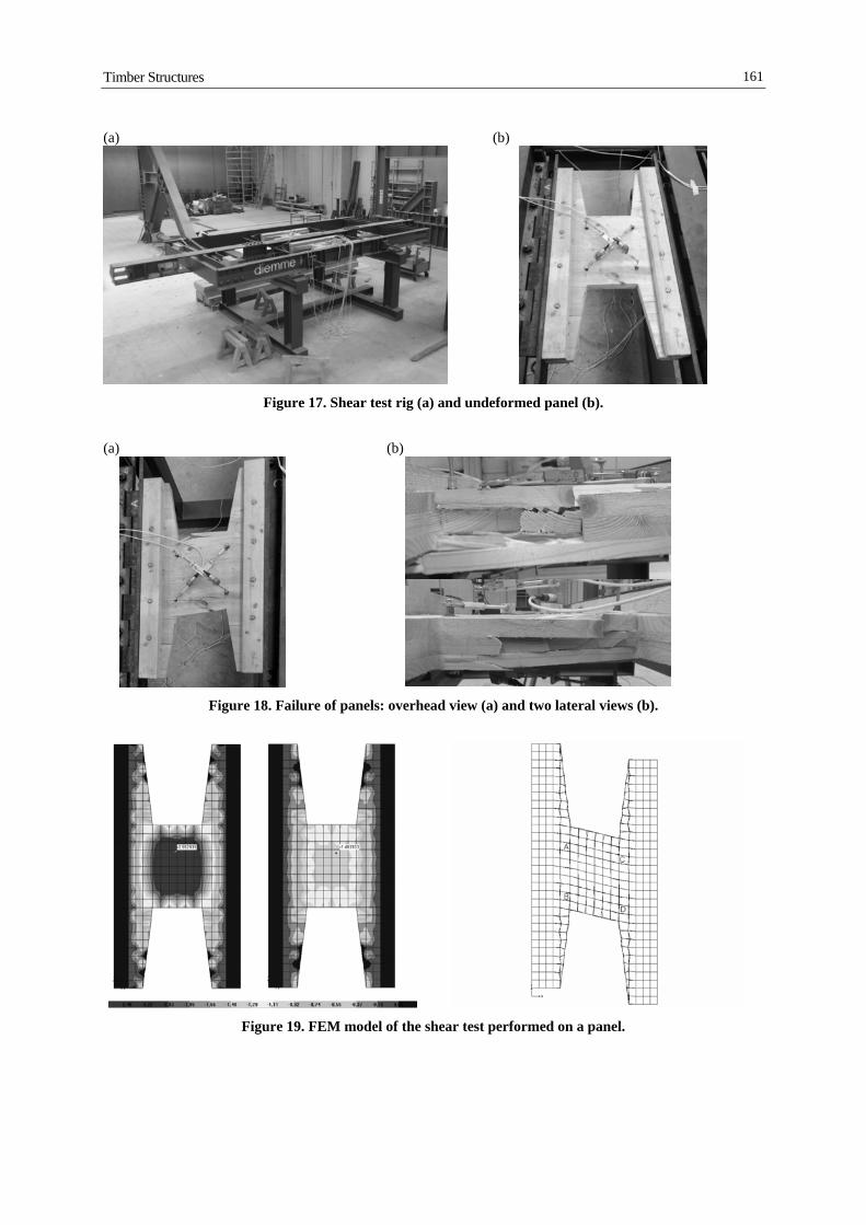
Some preliminary documents regarding the analyses and the study of some aspects of the calculation and numerical simulation of timber frame structures were processed in order to draft some guidelines accompanied with a case study. A new series of shear tests was completed on only 3-layer CLT panels suitable to create the diaphragm effect in restoration and retrofit interventions on existing buildings (Figures 17, 18). The experimental results were compared with the outputs of numerical models. Panel shear strength values are compatible with stress levels induced in the building diaphragms subjected to horizontal seismic forces (Figure 19). Four Timber-to-CLT composite section beams were tested. The CLT panels were made only of 3 layers for a total height of 6 cm. Timber screws were used to connect the panel to the beam. Linear and non-linear models of the beams were analysed by means of FEM simulation and the shear-slip screw correlation was calibrated on force-slip experimental tests.
Timber Structures
161
(a) (b)
Figure 17. Shear test rig (a) and undeformed panel (b).
(a) (b)
Figure 18. Failure of panels: overhead view (a) and two lateral views (b).
Figure 19. FEM model of the shear test performed on a panel.

M. Piazza, P. Zanon, C. Loss
162
The numerical model developed by the UR of Sassari (Rinaldin et al. 2013) has been used to simulate the behaviour of CLT and light-frame buildings. Two different buildings were modelled:
I. a CLT single-storey building tested by IVALSA at the University of Trento;
II. a light-frame building tested by Fischer et al. (2001) in the US.
CLT building A single-storey CLT building was tested at the University of Trento by CNR-IVALSA. This building is composed by an assemblage of CLT panels connected to the foundation with angle brackets and hold-downs. The connectors used, with the same number of nails, had been singularly tested previously. The building is 7×7 m in plan and 3.1 m high. The walls are 85 mm thick and the floor is 142 mm thick with a central opening (Figure 20a).
Figure 20. (a) 3D views of the single-storey CLT building model with springs marked with crosses; (b)
deformed shape with 20 times amplification factor (Rinaldin et al., 2014).
Pseudo-dynamic tests were performed in three different configurations obtained by varying the width of the door openings. In this work, the configuration with a non-symmetric layout with respect to the direction of the actuator (Figure 20b) was investigated. This configuration has two external openings, 4.0 m and 2.25 m wide, respectively. All the wooden parts have been modelled in Abaqus with elastic shell elements (S4R). The size of the adopted mesh is a convenient value to ensure that the connections are placed as close as possible to their real position and that the elements are regular 5304 springs used and placed with the help of an automatic mesh-maker developed on purpose; their location is visible in Figure 20a. Every spring has the parameters obtained by calibrations made on experimental data of single connectors (Gavric et al., 2011 and 2012); all wall-to-wall joints have the properties of LVL spline connection tests (Gavric et al., 2012), while every single floor panel is connected to the adjacent ones with half-lap screwed joints (Gavric et al., 2012).

Timber Structures
163
(a)
(b)
Figure 21. Experimental-numerical comparison of the hysteretic cycles (a) and time-history of total energy (b) of the single-storey X-lam building tested by CNR-IVALSA at the Univ. of Trento, Progetto Sofie
(Rinaldin et al., 2013a). The vertical connections between perpendicular walls were modelled using springs with the same properties as the springs used for in-plane wall-to-wall connections. The building was subjected to a pseudo-dynamic test that simulated the earthquake of Kobe JMA 0.5g. A non-linear static analysis was performed, imposing the seismic displacement at the top of the building. A typical deformed shape can be seen in Figure 20b, while results in terms of total base shear force vs. top displacement are presented in Figure 21a. An overall good accuracy of the experimental behaviour can be observed; the CLT walls did not deform considerably as most of the deformation was concentrated in the springs. The numerical model slightly overestimates the backbone response of the building. In Figure 21b, numerical and experimental responses are compared in terms of total energy.

M. Piazza, P. Zanon, C. Loss
164
The final numerical value of the total energy is 2.85% higher than the experimental one, due essentially to some approximations of the narrow inner cycles that the model predicts at low displacement amplitude (Figure 21a). Light-frame building A light-frame building tested by Fischer et al. (2011) was modelled and the results were compared with the experimental data. The 2-storey building was made with light-frame walls as displayed in Figure 22a. The building is 4.88×6.11 m (16×20 ft) in plan and 2.44 m high. The building was modelled using a couple of diagonal springs for each light-frame wall, arranged as in Figure 22b. The same wall arrangement as in the numerical model developed by Du (2003) was used. Du’s model used the cyclic results of the 2.44×2.44 m light-frame wall tested by Dolan (1989) to characterise the building. For this reason, the geometry of the building was slightly modified to accommodate the different properties of the wall tested in Dolan (1989). Each wall was modelled using two diagonal springs and rigid truss elements pin connected to each other, representing the perimeter frames of the wall. The diagonal springs were calibrated upon the experimental results reported in Dolan (1989). The model was restrained with simple supports at the base and the kinematic hypothesis of rigid floor diaphragms was applied. A modal analysis was performed, returning a natural vibration frequency of 5.25 Hz, which is fairly close to the value of 5.03 Hz found by Du (2003). A dynamic analysis was then performed, using the Northridge ground motion (Newhall station, 90° component, 1994). The analysis was stopped when the first storey reached a drift equal to 3% of the building height, which is regarded as an upper limit corresponding to the attainment of the collapse limit state in Du (2003).
(a) (b)
Figure 22. (a) Photo of the tested building (Fischer et al., 2001) and (b) layout of the resisting walls (Rinaldin et al., 2013b).

Timber Structures
165
5 DISCUSSION
The Research Units (RUs) involved in this task of the RELUIS project have dealt primarily with the study of the seismic behaviour of timber buildings. The goal of the work team was to define simple design guidelines based on the results obtained from the experiments and numerical analyses carried out. With particular reference to the tests performed on full scale elements, it has been possible to evaluate the non-linear behaviour of the elements also and especially in relation to the connecting devices used. The collapse mechanisms have been defined for structural elements, energy dissipation capacity, ductility and other performance parameters (Figure 23). The tests helped to deepen the state of knowledge on the current construction techniques, on the construction practices and on the materials used in the construction of timber modern buildings. In addition, starting from the tests, it has been possible to verify some limits of applicability of the rules and models included in the current versions of the standards, in particular the “Technical Standards for Constructions 2008” (CS.LL.PP., 2008) and “Eurocode 8” (CEN, 2004), for the part related to timber constructions. (a) (b)
Figure 23. Experimental tests carried out at the Materials and Structural Testing Laboratory of the University of Trento: on CLT walls (a) and timber framed walls (b). At the lower side, some failure
mechanisms observed. The part of work that focused on the numerical analyses has been crucial to clarify the role of FEM models in the assessment of the global response of timber buildings. The implementation of appropriate models for this purpose is a process that focuses on the knowledge of the real behaviour observed experimentally on elements or structural components. In case it is needed to implement non-linear analyses, it is necessary to consider and adequately describe the behaviour of connections with force-displacement links, calibrated on the experimental results. The accuracy level of the FEM model must be
M. Piazza, P. Zanon, C. Loss
166
compatible with the quality of data available to describe the behaviour of the connections and the building elements. The work carried out by the Research Units has also proposed equivalent macro-element models (Loss et al. 2013b), sufficiently reliable for a simplified evaluation of the seismic resistance of buildings. This work, which points out some of the most important aspects regarding the seismic design, namely calculation criteria, dimensioning rules, analyses, constructive specifications and rules for the implementation, may be used in the future for the preparation of a handbook for the design and construction of timber buildings.
6 VISIONS AND DEVELOPMENTS
The current "Technical Standards for Constructions" (NTC 2008), together with "Eurocode 8", are regulation documents updated to the modern philosophy of "performance-based" seismic design. A "performance" planning should permit full freedom and operation to the designer in identifying the most suitable tools to size the structure. The focus of the legislator is then directed to the levels of security to adopt and to the calculation principles to follow. Specifically, the designer is given greater freedom in the search for optimal structural solutions, then verifying the achievement of the safety levels established by the legislator in respect of the protection of human life and structural collapse. The work deriving from this task considered the seismic dimensioning of timber buildings, especially in relation to the possibility of creating earthquake-resistant buildings with a dissipative structural behaviour. In this context, some limits of applicability of the rules contained in the aforementioned documents have been identified, especially considering the current construction technologies and assembly techniques. If we refer to the dissipative structural behaviour of the structure, the NTC 2008 and, similarly, the Eurocode 8 provide guidelines on the materials to be used, the connections, the ductility and the structure factor (q), expressed as the maximum value and defined as a function of the construction typology. The choice of the most appropriate structure factor (q) is a very delicate and not easy operation and, unfortunately, the current NTC 2008 only establish the upper limit value for each structural typology. The use of a given factor q supposes a priori a well-defined dissipative structural behaviour, which is expressed in the ability of the structure to provide defined levels of ductility and energy dissipation capacity, as well as resistance to the acting loads. As shown in the carried out work, these features can be guaranteed only by a suitable definition of the connections. The use of a determined value for the parameter q means properly dimensioning the connections, especially in relation to the application of the capacity design. Therefore, it is acceptable to reduce the level of design seismic action, provided that the construction system is able to accept certain levels of inelastic deformation - the latter mainly governed by the capacity offered by the connections. The inelastic behaviour of the two structural types of reference for the task - CLT panels and framed panels - proved to be significantly different, especially if we consider the collapse failure mechanism. In Figure 24 it is possible to distinguish the two wall mechanisms: (i) a shear deformation mode (sliding) that involves the connectors placed between the covering panel and the frame for framed panel systems and (ii) a rigid rotation deformation mode, where the rotations are triggered by the deformation of the basic connections (failure of hold-down or similar devices) for CLT panel systems. In accordance with the current version of the NTC 2008, there will be two distinct maximum values of the factor q0 equal to 5 and 2, respectively for framed and CLT panels. However, the choice of the value to be used in the design phase is a function of the ductility class of the

Timber Structures
167
system ('A' or 'B' according to NTC 2008, and 'H' or 'M' according to EC8). In the case of framed panel systems, the shear mechanism is generally ductile according to the failure mode triggered at the level of the single connector (typically the nail). The failure mode for the nail can be controlled by adopting a sufficient slenderness (ratio between the thickness of the connected elements and the diameter of the connector). The standard defines some limits on the maximum diameter (d) to be considered for the connectors, on the density of some types of panels and on the minimum slenderness (λd) to ensure (e.g. d=3.1 mm, ρk=650 kg/m3 for particle panels defined in EN 312, λd = 4 for CD 'A' class). The deformation is generated by the sliding of the connectors placed at the edges of the frame. Normally, given the static redundancy of the shear wall element, it is easy to reach levels of ductility of about 2÷3 and beyond. In particular, this is possible by appropriately controlling the slenderness of the individual nail/connector and the strength of the steel used, as mentioned in Eurocode 8 (CEN, 2004). However, to ensure the formation of this mechanism, it is necessary to sufficiently dimension the basic connections (e.g. shear angle brackets and hold-down) so as to ensure the development of the wall element capacity. Failures in the basic connections (Figure 25) are to be avoided before the development of the maximum 'diaphragm' capacity of the walls. (a) (b)
Figure 24. (a) Mechanism of inelastic deformation of a light framed wall with shear deformation; (b) mechanism of inelastic deformation of a CLT wall following the collapse in the ground anchoring devices
(Loss et al. 2013a). Some of the tests performed within this research have highlighted premature failures in ground anchoring devices, resulting in a reduction of the inelastic-dissipative effective capacity and the subsequent reduction of the maximum acceptable value for the structure factor q. In fact, the standard, as it is written, seems to focus exclusively on the local behaviour of the connectors, defining rules on geometry and materials, and forgetting the role played by the ground connecting devices which are normally used in the assembly of structural components (hold-down, metal brackets, perforated metal strips, bars and other mechanical devices). In the absence of specific assessments, it is worth limiting the value of the factor q to a maximum value equal to 3, fully respecting the rules expected for the structures with a high ductility class. If high q factors are used (in the range of 4÷5), then it would be worth justifying this assumption in the planning stage through experimental tests or scientific documentation of proven reliability.
M. Piazza, P. Zanon, C. Loss
168
(a) (b)
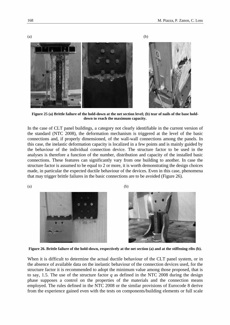
Figure 25 (a) Brittle failure of the hold-down at the net section level; (b) tear of nails of the base hold-
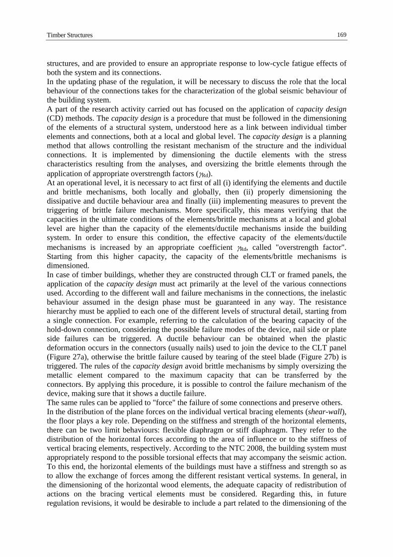
down to reach the maximum capacity. In the case of CLT panel buildings, a category not clearly identifiable in the current version of the standard (NTC 2008), the deformation mechanism is triggered at the level of the basic connections and, if properly dimensioned, of the wall-wall connections among the panels. In this case, the inelastic deformation capacity is localized in a few points and is mainly guided by the behaviour of the individual connection device. The structure factor to be used in the analyses is therefore a function of the number, distribution and capacity of the installed basic connections. These features can significantly vary from one building to another. In case the structure factor is assumed to be equal to 2 or more, it is worth demonstrating the design choices made, in particular the expected ductile behaviour of the devices. Even in this case, phenomena that may trigger brittle failures in the basic connections are to be avoided (Figure 26). (a) (b)
Figure 26. Brittle failure of the hold-down, respectively at the net section (a) and at the stiffening ribs (b). When it is difficult to determine the actual ductile behaviour of the CLT panel system, or in the absence of available data on the inelastic behaviour of the connection devices used, for the structure factor it is recommended to adopt the minimum value among those proposed, that is to say, 1.5. The use of the structure factor q as defined in the NTC 2008 during the design phase supposes a control on the properties of the materials and the connection means employed. The rules defined in the NTC 2008 or the similar provisions of Eurocode 8 derive from the experience gained even with the tests on components/building elements or full scale
Timber Structures
169
structures, and are provided to ensure an appropriate response to low-cycle fatigue effects of both the system and its connections. In the updating phase of the regulation, it will be necessary to discuss the role that the local behaviour of the connections takes for the characterization of the global seismic behaviour of the building system. A part of the research activity carried out has focused on the application of capacity design (CD) methods. The capacity design is a procedure that must be followed in the dimensioning of the elements of a structural system, understood here as a link between individual timber elements and connections, both at a local and global level. The capacity design is a planning method that allows controlling the resistant mechanism of the structure and the individual connections. It is implemented by dimensioning the ductile elements with the stress characteristics resulting from the analyses, and oversizing the brittle elements through the application of appropriate overstrength factors (γRd). At an operational level, it is necessary to act first of all (i) identifying the elements and ductile and brittle mechanisms, both locally and globally, then (ii) properly dimensioning the dissipative and ductile behaviour area and finally (iii) implementing measures to prevent the triggering of brittle failure mechanisms. More specifically, this means verifying that the capacities in the ultimate conditions of the elements/brittle mechanisms at a local and global level are higher than the capacity of the elements/ductile mechanisms inside the building system. In order to ensure this condition, the effective capacity of the elements/ductile mechanisms is increased by an appropriate coefficient γRd, called "overstrength factor". Starting from this higher capacity, the capacity of the elements/brittle mechanisms is dimensioned. In case of timber buildings, whether they are constructed through CLT or framed panels, the application of the capacity design must act primarily at the level of the various connections used. According to the different wall and failure mechanisms in the connections, the inelastic behaviour assumed in the design phase must be guaranteed in any way. The resistance hierarchy must be applied to each one of the different levels of structural detail, starting from a single connection. For example, referring to the calculation of the bearing capacity of the hold-down connection, considering the possible failure modes of the device, nail side or plate side failures can be triggered. A ductile behaviour can be obtained when the plastic deformation occurs in the connectors (usually nails) used to join the device to the CLT panel (Figure 27a), otherwise the brittle failure caused by tearing of the steel blade (Figure 27b) is triggered. The rules of the capacity design avoid brittle mechanisms by simply oversizing the metallic element compared to the maximum capacity that can be transferred by the connectors. By applying this procedure, it is possible to control the failure mechanism of the device, making sure that it shows a ductile failure. The same rules can be applied to "force" the failure of some connections and preserve others. In the distribution of the plane forces on the individual vertical bracing elements (shear-wall), the floor plays a key role. Depending on the stiffness and strength of the horizontal elements, there can be two limit behaviours: flexible diaphragm or stiff diaphragm. They refer to the distribution of the horizontal forces according to the area of influence or to the stiffness of vertical bracing elements, respectively. According to the NTC 2008, the building system must appropriately respond to the possible torsional effects that may accompany the seismic action. To this end, the horizontal elements of the buildings must have a stiffness and strength so as to allow the exchange of forces among the different resistant vertical systems. In general, in the dimensioning of the horizontal wood elements, the adequate capacity of redistribution of actions on the bracing vertical elements must be considered. Regarding this, in future regulation revisions, it would be desirable to include a part related to the dimensioning of the

M. Piazza, P. Zanon, C. Loss
170
connections among the individual modular elements of the floor in order to ensure an adequate transmission capacity of the actions and to control the global deformation of the floor in its plane.
(a) (b)
Figure 27. Tensile failure of the ground anchorage devices (hold-down): ductile mechanism with deformation in the nails (a) and brittle mechanism with failure in the net section (b).
In conclusion, it is worth considering the evolution still going on for timber construction systems that is leading to the construction of buildings with a considerable vertical development. Especially for medium-high residential buildings, it becomes essential to also consider the problem of structural 'robustness'. To that end, an adequate capacity to redistribute any stresses along alternative load paths compared to the project paths must be given to the structures, in case a structural element loses its resistant capacity due to unexpected events. The structures must therefore possess an adequate degree of redundancy (but ensuring ductility to the connections) and/or systems able to receive the actions in the event of failure of the structural elements must be defined so as to prevent the generalized collapse of the structure. In any case, the structure must possess such capacity in order to avoid excessive damages (i.e. collapse) compared to exceptional actions (e.g. fire, earthquake, explosion, shocks or consequences of human errors, etc.). All the problems here mentioned will represent interesting starting points for new research developments, which will be useful in the updating activities of the technical rules, both national (NTC) and European (Eurocodes).
7 MAIN REFERENCES
Calderoni B., Giubileo C., Sandoli A. (2013). “Criteri di progettazione strutturale di edifici in legno a pannelli XLam”, Proceeding of the 15th Italian Conference on Earthquake Engineering (ANIDIS 2013), Padua, Italy.
CEN (2004). Eurocode 8: Design of structures for earthquake resistance. Part 1-1: General rules, seismic actions and rules for buildings, European Committee for Standardization, Bruxelles, Belgium.
CS.LL.PP. (2008). DM 14 Gennaio 2008, Norme Tecniche per le Costruzioni, Gazzetta Ufficiale della Repubblica Italiana 29, Italia.
Fischer D., Filiatrault A., Folz B., Uang C.M., Seible F. (2001). “Shake table tests of a two-storey woodframe house”, CUREE-Caltech Woodframe Project, Department of Structural Engineering, University of San Diego, California, The USA.

Timber Structures
171
Gardino P. (2011). “Il mercato italiano delle case in legno nel 2010. Analisi del mercato. Previsioni fino al 2015”, Presentazione al MADE expo 2011. Pubblicazione di promo_legno in collaborazione con Assolegno di FederlegnoArredo.
Gattesco N., Franceschinis R. (2012). “Experimental investigation on the seismic behavior of timber shear walls with particle boards”, Proceedings of the 12th World Conference on Timber Engineering (12WCTE), Session 40, (Design 14): 356-361, Auckland, New Zealand.
Germano F., Metelli G., Giuriani E. (2013). “Studio sperimentale di pareti portanti a pannelli intelaiati in legno”, Proceeding of the 15th Italian Conference on Earthquake Engineering (ANIDIS 2013), Padua, Italy.
Germano F., Metelli G., Giuriani E. (2013b). “Experimental study on light-frame shear walls”, Proceeding of the 15th Italian Conference on Earthquake Engineering (ANIDIS 2013), Padua, Italy. (in italian).
Germano F., Metelli G., Giuriani E. (2014) “Role of the connections on the overall behavior of timber frame shear walls: experimental results”, Paper submitted to an international ISI journal.
Germano F., Metelli G., Marroni F., Giuriani E. (2012). Experimental study on connections for wood-frame shear walls of multi-storey buildings, Department of Civil, Environmental, Architectural Engineering and of Mathematics, University of Brescia, Technical Report n. 3, (in Italian).
Germano F., Metelli G., Marroni F., Giuriani E., Parisio C. (2013c). Analytical study on wood-frame shear walls, Technical Report No. 3, 2013, Department of Civil, Environmental, Architectural Engineering and of Mathematics, University of Brescia, 51 p. (in Italian).
Germano F., Metelli G., Marroni F., Giuriani E., Parisio C., Piovani C., (2013)a. Experimental study on wood-frame shear walls, Technical Report No. 2, Department of Civil, Environmental, Architectural Engineering and of Mathematics, University of Brescia, 115 p. (in Italian).
Loss C., Piazza M., Zonta D. (2013a). “Timber structures” in T.J. Sullivan, G.M. Calvi editors, Development in the Field of Displacement-Based Seismic Assessment: 295-338, Pavia: IUSS Press. ISBN: 978-88-6198-090-7.
Loss C., Piazza M., Zonta D., Soraruf M. (2013b). “Studio del comportamento dinamico di edifici in legno: calibrazione di un modello a macroelementi equivalent”, Proceeding of the 15th Italian Conference on Earthquake Engineering (ANIDIS 2013), Padua, Italy.
Metelli G., Preti M., Azzini G., Bolis V., Giuriani E. (2012). Comparative analysis of sismo-resistant timber systems for multi-storey buildings. Department of Civil, Environmental, Architectural Engineering and of Mathematics, University of Brescia, Technical Report n. 1, (in Italian).
Racher P. (1995). “Mechanical timber joints – General”, In Timber Engineering Lecture C1, STEP/EUROFORTECH, Centrum Hout, Almere, The Netherlands.
Rinaldin G., Amadio C., Fragiacomo M. (2013a) “A component approach for the hysteretic behaviour of connections in cross-laminated wooden structures”, Earthquake Engineering and Structural Dynamics, (in press). DOI: 10.1002/eqe.2310.
Rinaldin G., Fragiacomo M. (2014). “A Component Model for Cyclic Behaviour of Wooden Structures”, Materials and Joints in Timber Structures: 519-530.
Rinaldin G., Herve Poh’sie G., Amadio C., Fragiacomo M. (2013b) “Modelling the seismic behaviour of light-frame timber structures”, International Journal of Earthquake Engineering 1 (Ingegneria Sismica), IUSSPress, Pavia, Italy.
8 RELUIS REFERENCES
Acler E., Piazza M., Tomasi R., Webber M. (2011). “Experimental investigation of the behaviour of different types of connections between the XLAM panels and the concrete slab”, Proceedings of the Structural Engineering World Conference, Cernobbio, Como, Italy.
Angeli A., Piazza M., Riggio M.P., Tomasi R. (2010). “Refurbishment of traditional timber floors by means of wood-wood composite structures assembled with inclined screw connectors”, Proceedings of the 11th World Conference on Timber Engineering: 3569-3576, Riva del Garda, Italy.
M. Piazza, P. Zanon, C. Loss
172
Casagrande D., Rossi S., Sartori T., Tomasi R., Piazza M. (2012). “Analytical and numerical analysis of timber framed shear walls”, Proceedings of the 12th World Conference on Timber Engineering (12WCTE), Strength and Serviceability – Extreme Events: 278-284, Auckland, New Zealand.
Conte A., Piazza M., Sartori T., Tomasi R. (2011). “Experimental investigation on connections between wood framed shear walls and foundations”, Proceedings of the Structural Engineering World Conference, Cernobbio, Como, Italy.
Conte A., Piazza M., Sartori T., Tomasi R. (2011). “Influence of sheathing to framing connections on mechanical properties of wood framed shear walls”, Proceeding of the XIV ANIDIS conference (L'Ingegneria Simica in Italia), 172: 1292-1473, Bari, Italy.
Giongo I., Piazza M, Tomasi R. (2012). “Out of plane refurbishment techniques of existing timber floors by means of timber to timber composite structures”, Proceedings of the 12th World Conference on Timber Engineering (12WCTE), Session 45 (Design 15): 544-550, Auckland, New Zealand.
Giongo I., Piazza M., Tomasi R. (2011). “Soluzioni di rinforzo di solai lignei mediante tecniche legno-legno nelle operazioni di miglioramento sismico di edifici esistenti”, Proceeding of the XIV ANIDIS conference (L'Ingegneria Simica in Italia), 167: 946-1485, Bari, Italy.
Loss C. (2011). Displacement-based seismic design of timber structures, Ph.D. thesis, University of Trento, Trento, Italy, (URL: http://eprints-phd.biblio.unitn.it/593/1/PHD_THESIS_C_LOSS_DEPOSITO.pdf).
Loss C., Luchetti M., Piazza M., Andreolli M. (2013a). Indicazioni per la progettazione e la direzione lavori di edifici in legno in zona sismica, Assolegno-FederlegnoArredo (MADEexpo 2013), Milano, Italy.
Loss C., Piazza M., Zonta D. (2012). “Analytical model to evaluate the equivalent viscous damping of timber structures with dowel-type fastener connections,” Proceedings of the 12th World Conference on Timber Engineering (12WCTE), Session 29 (Connections 9): 516-525, Auckland, New Zealand.
Loss C., Piazza M., Zonta D. (2013). “A new method to assess the seismic vulnerability of existing wood frame buildings,” Proceedings of the 2nd International Conference on Structural Health Assessment of Timber Structures, in Advanced Materials Research: 486-494, Trento, Italy. DOI: 10.4028/www.scientific.net/AMR.778.486.
Loss C., Piazza M., Zonta D. (2013). “Seismic design of timber buildings with a direct displacement-based design method,” Proceedings of the 2nd International Conference on Structures and Architecture, in Structures and Architecture: 98-105, Guimaraes, Portugal. DOI: 10.1201/b15267-14.
Loss C., Zonta D., Piazza M. (2013). “On Estimating the Seismic Displacement Capacity of Timber Portal-Frames”, Journal of Earthquake Engineering 17 (6): 879-901. DOI: 10.1080/13632469.2013.779333.
Loss C., Piazza M., Zonta D. (2013b). “A new method to assess the seismic vulnerability of existing wood frame buildings,” Proceedings of the 2nd International Conference on Structural Health Assessment of Timber Structures, in Advanced Materials Research: 486-494, Trento, Italy. DOI: 10.4028/www.scientific.net/AMR.778.486.
Loss C., Piazza M., Zonta D. (2013c). “Seismic design of timber buildings with a direct displacement-based design method,” Proceedings of the 2nd International Conference on Structures and Architecture, in Structures and Architecture: 98-105, Guimaraes, Portugal. DOI: 10.1201/b15267-14.
Piazza M., Riggio M., Tomasi R., Giongo I. (2010). “Comparison of In Situ and Laboratory Testing for the Characterization of Old Timber Beams before and after Intervention” Gu, X., Song, X. editors, Advanced Materials Research Vols. 133-134: 1101-1106. URL:http://www.scientific.net/AMR.133-134.1101.pdf.
Riggio M., Tomasi R., Piazza M. (2014). “Refurbishment of a Traditional Timber Floor with a Reversible Technique: The Importance of the Investigation Campaign for the Design and the Control of the Intervention”, International Journal of Architectural Heritage: Conservation, Analysis, and Restoration, 8(1): 74-93 (available online: 23 Apr 2012). DOI: 10.1080/15583058.2012.670364.
Zonta D., Loss C., Piazza M., Zanon P. (2011). “Direct Displacement-Based Design of glulam timber frame buildings”, Journal of Earthquake Engineering 15: 491-510. DOI: 10.1080/13632469.2010.495184.