maunakea spectroscopic explorer (mse): the prime focus
TRANSCRIPT

PROCEEDINGS OF SPIE
SPIEDigitalLibrary.org/conference-proceedings-of-spie
Maunakea Spectroscopic Explorer(MSE): the prime focus subsystems:requirements and interfaces
Alexis Hill, Alexandre Blin, David Horville, Shan Mignot,Kei Szeto
Alexis Hill, Alexandre Blin, David Horville, Shan Mignot, Kei Szeto,"Maunakea Spectroscopic Explorer (MSE): the prime focus subsystems:requirements and interfaces," Proc. SPIE 10705, Modeling, SystemsEngineering, and Project Management for Astronomy VIII, 1070529 (10 July2018); doi: 10.1117/12.2314387
Event: SPIE Astronomical Telescopes + Instrumentation, 2018, Austin, Texas,United States
Downloaded From: https://www.spiedigitallibrary.org/conference-proceedings-of-spie on 9/4/2018 Terms of Use: https://www.spiedigitallibrary.org/terms-of-use

Th
b Divis
c GEPI, Ob
MSE will beprime focusspectrograph
We describe the MSE primtelescopes antheir Conceplower-level rdiscuss the iforward. We for instrumen
Keywords: M
The Maunaka dedicated otelescope wiinfrared, at llarge aperturmillions of sprecisely to f
During the roverall scienlimits. Durin
1 Email: hill@
Mhe Prime
a CFHT Corion Techniq
bservatoire d
e a massively m, including an
hs several tens o
the process ofme focus. Thisnd how those reptual Design Phrequirements annterface specifalso discuss th
ntation located
Maunakea Spe
kea Spectroscopoptical and neaith a 1.5 squarow, moderate
re and field of vspectra per yefeed banks of s
recent Conceptnce requiremenng this process,
@cfht.hawaii.e
Maunakee Focus S
Alexis H
rporation, 65que de l’INSU
de Paris, PSLCité, Pla
multiplexed surn array of apof meters away
f mapping top-ls includes the equirements whases. We thennd specificatiofications, theirhe opto-mecha
d at the top end
ctroscopic Exp
pic Explorer (Mar-infrared (NIRre degree fieldand high specview by includ
ear. The multispectrographs s
tual Design Phnts [2], system , subsystem de
edu; Telephone
a SpectroSubsystemHill1a, Alexa
Shan Mig
5-1238 MamU, Bureau d
MeuL Research Uace Jules Jan
AB
rvey telescopepproximately y.
level requiremoverall top-lev
were converted n discuss the vons into higher r effect on the anical design of.
plorer, multi-ob
1. INTMSE) is an upgR) spectroscopd of view locatral resolutionding a massiveplexing includseveral tens of
hase (CoDP) oarchitecture a
esigners develo
e: 808-885-318
oscopic Ems: Requandre Blinb, Dgnotc, Kei Sz
malahoa Hwyd’études mécudon, FranceUniversity, Cssen, 92195
BSTRACT
, including a sfour thousand
ments on MSE tvel requiremeninto specificatierification of tlevel performaperformance o
f the telescope
bject spectrogr
TRODUCTIgrade of the 3.6pic survey facilated at a primes. MSE’s first-
ely multiplexeddes an array ometers away.
of MSE [1] suband other constoped practical d
87
Explorer uirementDavid Horvizetoa,
y, Kamuela, Hcanique, 1 ple, CNRS, UnivMeudon, Fr
segmented primd fibers, posi
to technical spents based on knions so that thethe engineeringance budgets (of the system
e top end assem
raph, prime foc
ION 6-m Canada Frlity. MSE is ple focus. MSE -light instrumed fiber-fed systof approximate
bsystem desigtraints such asdesigns, based
(MSE) ts and Intillec
Hawaii 9674ace Aristide
v Paris Diderrance
mary mirror whtioned precise
ecifications fornowledge of sie subsystems cg specificatione.g. Image Quand the plan t
mbly and refer r
cus, requiremen
rance Hawaii Tlanned as 10-m
will operate ientation suite ttem that will bely four thous
ns were devels environmentad on previous e
terfaces
43, USA
Briand, 921
rot, Sorbonn
hich feeds fibeely to feed b
r subsystems loimilar systems ould begin wo
ns and the compuality). We alsto manage thereaders to mor
nts, interfaces
Telescope (CFHmeter effective in the optical takes advantage capable of co
sand fibers, po
loped based onal conditions aexperience with
195
e Paris
ers at the banks of
ocated at at other
orking on piling of o briefly m going re details
HT) into aperture to near-
ge of this ollecting ositioned
n MSE’s and mass h similar
Modeling, Systems Engineering, and Project Management for Astronomy VIIIedited by George Z. Angeli, Philippe Dierickx, Proc. of SPIE Vol. 10705
1070529 · © 2018 SPIE · CCC code: 0277-786X/18/$18
Proc. of SPIE Vol. 10705 1070529-1Downloaded From: https://www.spiedigitallibrary.org/conference-proceedings-of-spie on 9/4/2018Terms of Use: https://www.spiedigitallibrary.org/terms-of-use

hardware. Thconcept and
With the conbased requirmaximizing s
This paper dfocus. A destelescope topdefine the su
The overall lprimary mirrcorrector/atm
MSE elevatiostructure rotasix spiders anon a large cstructure. Thare located in
Figure 1
The prime foMSE packs 4light from in
he results of thfor creating rea
nceptual designrements. The osensitivity is d
discuss the macription of thep end assembl
ubsystems at th
layout of the oror (M1) and
mospheric dispe
on and azimuthates on small trnd an interfacecircular track ahe platforms supn the Coudé ro
. Overall archite
ocus is a conve4332 fibers, mndividual targe
his work were ualistic overall s
ns complete, Moverall systemescribed in [4]
apping of top le prime focus ily conceptual e prime focus g
2
observatory is an 11.25-m e
ersion correcto
h structures prrunnions and se support ring, and supports tpport a bank oom of the teles
ecture of MSE.
ex focal surfaceounted in fiber
ets and transm
used to informsystem perform
MSE project oms engineering
. MSE is now
level requireminstruments of designs. We dgoing forward.
2. OBSERV
shown in Figuentrance pupil
or (WFC/ADC)
ovide support upports M1 sewhich supportthe elevation f low-moderatscope pier.
e (see Figure 2r positioning a
mit it to banks
m the plans for mance budgets.
office has compprocess for th
preparing to pr
ments to technif MSE are includiscuss the re.
VATORY L
ure 1. MSE il (10-m effect) to create the p
during observaegments in a mts all of the primstructure as w
te resolution sp
2) with a 1.52 sactuators, in a hof spectrograp
the observator.
pared system phe project is droceed with its
cal specificatiouded, as well aquirements, in
LAYOUT
s an altitude-ative diameter)prime focus at
ations, over themirror cell. At it
me focus subsywell as instrumpectrographs. A
square degreeshexagonal arraphs. The remai
ry system archi
performance bdescribed in [s Preliminary D
ons for the suas a more detanterfaces and c
azimuth telesco. M1 reflects the top end of
e full range of ts top end, the ystems. The az
ment platformsA set of high re
s field of view ay inside the fiining edges of
itecture and op
budgets to the [3] and the prDesign Phase (P
ubsystems at thailed descriptioconstraints wh
ope with a 60-light to a wi
f the telescope.
f motion. The eelevation struc
zimuth structurs on both sideesolution spectr
(584 mm in dield of view, tof the field of v
perations
science-ocess of PDP).
he prime on of the hich will
-segment ide field
elevation cture has re rotates es of the rographs
iameter). o capture view are
Proc. of SPIE Vol. 10705 1070529-2Downloaded From: https://www.spiedigitallibrary.org/conference-proceedings-of-spie on 9/4/2018Terms of Use: https://www.spiedigitallibrary.org/terms-of-use
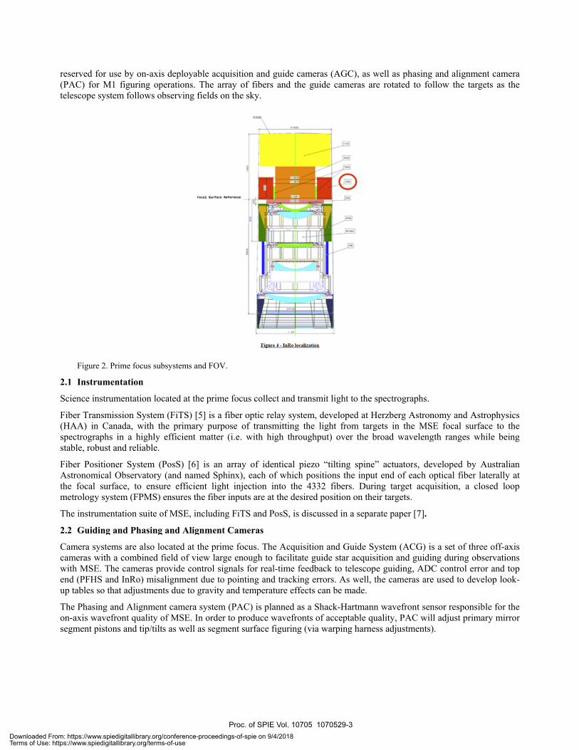
reserved for (PAC) for Mtelescope sys
Figure 2.
2.1 Instrum
Science instr
Fiber Transm(HAA) in Cspectrographstable, robust
Fiber PositioAstronomicathe focal sumetrology sy
The instrume
2.2 Guiding
Camera systecameras withwith MSE. Tend (PFHS aup tables so t
The Phasing on-axis wavesegment pisto
use by on-axisM1 figuring opstem follows ob
Prime focus sub
mentation
rumentation loc
mission SystemCanada, with thhs in a highly t and reliable.
oner System (Pal Observatory rface, to ensu
ystem (FPMS)
entation suite o
g and Phasing
ems are also loh a combined fThe cameras prand InRo) misathat adjustmen
and Alignmenefront quality oons and tip/tilt
s deployable acperations. The bserving fields
bsystems and FO
cated at the pri
m (FiTS) [5] is he primary puefficient matte
PosS) [6] is a(and named S
ure efficient liensures the fib
of MSE, includ
and Alignme
ocated at the prfield of view larovide control alignment due nts due to gravi
nt camera systeof MSE. In ords as well as seg
cquisition and array of fibers
s on the sky.
OV.
ime focus colle
a fiber optic reurpose of transer (i.e. with h
an array of ideSphinx), each oght injection
ber inputs are a
ding FiTS and P
nt Cameras
rime focus. Tharge enough tosignals for reato pointing anty and tempera
em (PAC) is plder to produce gment surface
guide camerass and the guid
ect and transmi
elay system, desmitting the lighigh throughpu
entical piezo “of which positiinto the 4332
at the desired p
PosS, is discus
he Acquisition o facilitate guidal-time feedbacd tracking erroature effects ca
lanned as a Shawavefronts of figuring (via w
s (AGC), as wde cameras are
it light to the sp
eveloped at Heght from targe
ut) over the br
“tilting spine” ions the input
2 fibers. Durinosition on thei
sed in a separa
and Guide Syde star acquisitck to telescopeors. As well, than be made.
ack-Hartmann acceptable qua
warping harnes
well as phasing e rotated to fol
pectrographs.
erzberg Astronets in the MSEroad waveleng
actuators, devend of each o
ng target acqur targets.
ate paper [7].
stem (ACG) istion and guidin
e guiding, ADChe cameras are
wavefront senality, PAC wills adjustments)
and alignmentllow the target
nomy and AstroE focal surfac
gth ranges whi
veloped by Auoptical fiber latuisition, a clos
s a set of threeng during obseC control errore used to devel
nsor responsibll adjust primar).
t camera ts as the
ophysics ce to the ile being
ustralian terally at sed loop
off-axis ervations r and top op look-
le for the ry mirror
Proc. of SPIE Vol. 10705 1070529-3Downloaded From: https://www.spiedigitallibrary.org/conference-proceedings-of-spie on 9/4/2018Terms of Use: https://www.spiedigitallibrary.org/terms-of-use

th (nm) 360 370
1oc 54% 61%
MR) 42% 46%
R) 58% 62%
400 482 626
79% 87% 81%
58% 72% 82%
70% 81% 88%
767 900 910
82% 84% 84%
85% 86% 86%
89% 89%
1300
81%
79%
2.3 Top End
The telescopthat are closeFocus Hexap
WFC/ADC icorrection anDT-INSU de
PFHS providcompensate fmaking theseare positionedispersion co
InRo providethe telescope
TEA concept
MSE strivesmultiplexingprime focus sthe majority These includbeen maximidesigns and c
3.1 Through
Throughput iof the originasubsystems o
Figure 3.
WFC/ADC tWFC/ADC i
For FiTS, thrlosses. Thesdesign of the
3.2 Noise
Noise is the sky backgrouof MSE and
d Assembly
e’s Top End Aely integrated pod System (PF
is based on thnd atmosphericesigned the WF
des top end sufor dimensionae moves, PFHSed at the focal sorrection.
es field derotate’s guide camer
tual designs ar
to take advang and to be a wesubsystems. Seof contributor
de quantities suized in MSE [compiling them
hput
is the amount oal target flux. Mof MSE, throug
Throughput of p
throughput is s also limited b
roughput effecse effects are
e subsystem at t
light that arrivund and other sis discussed in
Assembly (TEAwith the telesc
FHS) and Instru
he optical desc dispersion coFC barrel, an op
ubsystem posial changes of tS maintains thesurface and pro
tion as the teleras, ride on its
e discussed in
3. REntage of the eell-calibrated, ensitivity is qurs to SNR are puch as Noise, T[4], by considem in performan
of flux from anMore simply, tghput is applies
prime focus subs
dominated byby available op
cts due to the fconstraints onthe prime focu
ves at detectorsources) plus th
n a separate pap
A), developed bcope to supporrument Rotator
sign for MSE orrection and dpto-mechanica
itional correctithe telescope se alignment ofovides a small
escope followslarge-bearing m
more detail lat
EQUIREMEexcellent site ssurvey machin
uantified in sciepredetermined Throughput, Inering the contrnce budgets.
n astronomicalthroughput is ths to the WFC/A
systems.
y the optical dptical blank siz
fibers are consin the design ofus and are discu
rs in the spectrhe noise inhereper [7].
by DT-INSU inrt observationsr (InRo).
[8] and providelivers the coal assembly, to
ion in five destructure due tof the WFC barroffset as part o
s the sky. All imechanism.
ter in this pape
ENTS DEVseeing of Maune. Sensitivity oence requiremeby the system
njection Efficieributors from t
l target that reahe amount of lADC and FiTS
design, especizes, so vignettin
idered: Focal Rf the FiTS sysussed in a sepa
rographs from ent in the detec
n France, is a cs. This include
ides primary morrected focal s
align, support
egrees of freedo environmentarel to M1, ensuof the ADC co
nstruments loc
er.
VELOPMENunakea with thof MSE is affeents [2] by the
m architecture (ency (IE) and the as-designed
aches the deteclight transmitteS (for a summar
ially Fresnel, ng has an impa
Ratio Degradatstem but thesearate paper [7].
sources other ctor itself. Nois
collection of ths the WFC/AD
mirror wide fisurface at the tand protect th
dom (focus, deal and gravity ures the fibers ontrol action to
cated on the fie
NT he best possiblcted by physicsignal to noise
(e.g. aperture sImage Quality
d estimates of
ctor and is exped by the systemry see Figure 3
transmission aact on throughp
tion (FRD), Fr contributions
than the objecse is not a subj
hree related subDC, as well as
field optical abtelescope prime optics of this
ecenter and tiporientation effand the guide
o allow for atm
eld of view, as
le sensitivity, cal effects of ine ratio (SNR). size and field oy (IQ). Sensitif subsystem co
pressed as a pem. For the prim3).
and absorptionput.
esnel and transare not relate
ct being observect for the prim
bsystems a Prime
berration me focus. s system.
p/tilt) to fects. By cameras
mospheric
s well as
massive ndividual In MSE,
of view). ivity has nceptual
rcentage me focus
n losses.
smission ed to the
ved (e.g. me focus
Proc. of SPIE Vol. 10705 1070529-4Downloaded From: https://www.spiedigitallibrary.org/conference-proceedings-of-spie on 9/4/2018Terms of Use: https://www.spiedigitallibrary.org/terms-of-use

D
IS
ariation (um)C/ADC
da cameras5
Inni45 max
15 max
5 rms
Lone
30mi5 m:
2 rms
30mi6 mis
80 mi1 mi
14 max
2 1114
R.
Lateral chron
Residual DAR
Control systeax Axis tilt errorax Position error
Guiding errorax AIV PosS and
Closed loop a
ax Defocus of síax Gravity sag o'
Thermal effetax Thermal effet
Source
natic aberrationsdrift after ADC c,m rotation error((during guiding)
rs (during guiding)
FiTS
accuracy (after acsines (but median
ver an observatioi
ct over an observ+
ct over an observa
:orrection(during guiding)
quisition)modelled)n
ationation
3.3 Image Q
IQ is a measexpressed asinput. Contalignment err
Natural site subsystems asite.
WFC/ADC ofigure errorsduring opera
Observatory focus compo
3.4 Injectio
Keeping the percentage omodelled [9]microns. Theoffset error iprime focus s
Figure 4.
IE has controperational ediscussed in
The optical alignment todisplacementatmospheric atmospheric mitigated if baseline for caused by diof motion to
During the scameras as a
Quality
sure of how ms the diametrictributors that rors, and WFC
seeing and M1at the prime fo
optical design fs, glass homogtions) for the W
seeing can be onents are requi
n Efficiency
fiber input enof flux entering] as deviationse maximum amin the positionsubsystems con
Injection efficie
ributors that inerrors before athe previous se
design includelerances givents are presentdispersion codifferential reit were possiboperations, hofferential atmoprovide image
set-up for guida rigid body. Th
much an image 80% encircleaffect IQ are
C/ADC fabricat
1 segment errocus, however,
focused heavilygeneity errors)WFC/ADC as a
significantly aired to limit or
nds aligned wig the input fibs from the ideamount of attainn of the entire ntribute to IE (
ency of prime fo
nclude the optiand during obsection. The am
es contributionn in the optical t between anyorrection, evenfraction drift d
ble to repositioowever. Atmosospheric refrace quality at the
ing and acquishis compensate
e represented bed energy (EE8
grouped: natution and alignm
ors are, of couare designed b
y on IQ perform and alignmena rigid body an
affected by hear control their h
th the targets bre with respeal fibre locationable flux woufiber array or
(for a summary
ocus subsystems.
ical design, Aervations. IE i
mount of light th
ns inherent to design. WFC/
y PSFs betwn in a theoreduring observaon individual spheric disperstion. This redfocal surface t
sition, PFHS pes for flexure o
by its point sp80) of a 2D Mural site and
ment errors.
urse, out of thebased on the kn
mance and incnt errors (bothnd for individua
at distribution iheat dissipation
in the sky is cct to the total
on in two direculd enter the fiindividual fib
y, see Figure 4)
Assembly, Integis modelled cohat enters the f
a WFC/ADC /ADC has a lareen wavelengetically perfecations over a gPosS actuators
sion correctionduces distortionthat enables a s
positions the Wof the telescope
read functionMoffat distribut
observatory se
e control of thenown seeing c
ludes considerh during the aal optical elem
in the dome enn, especially ne
critical to the flux of a poi
ctions, longitudibre at z=0 anders, either late).
gration and Veonsidering the fiber decreases
that is designrge contributio
gths due to rect WFC/ADC.given zenith ras during an ob
n is included ton by half over tsmall fiber size
WFC/ADC pluse structure due
(PSF) is degration on the foceeing, M1 seg
e prime focus onditions on M
ration of errorsssembly proce
ments.
nvironment. Foear the optical p
IE of MSE, wnt source at thdinal (z) and ld xy=0. IE wierally or longit
erification (AIdelivered IQ adramatically i
ned and built won to IE, basedesidual chrom The system ange. This is abservation. Tho reduce the dithe most of thee.
s InRo, PosS, e to gravity and
aded and, for cal surface at tgment fabricat
systems of MMaunakea at th
due to fabricaess and due to
r that reason, apath.
which is definehe focal surfaclateral (xy), in ill be degradedtudinally. Mo
IV) phase actiat the focal surf the PSF is ex
within fabricatd on two effect
matic aberratioalso will ex
an effect that chis is not curreistortion in thee zenith distan
fiber inputs and temperature c
MSE, is the fibre tion and
MSE. The he CFHT
ation (i.e. o flexure
all prime
ed as the ce. IE is units of
d by any st of the
vity and rface, as
xtended.
tion and ts. Large
ons after xperience could be ently the e system
nce range
nd guide changes,
Proc. of SPIE Vol. 10705 1070529-5Downloaded From: https://www.spiedigitallibrary.org/conference-proceedings-of-spie on 9/4/2018Terms of Use: https://www.spiedigitallibrary.org/terms-of-use
with a small offset to allow for atmospheric dispersion correction action. This happens once at the beginning of an observation.
As a stand-alone system, PFHS is required to attain and maintain its position to within 0.15 mm laterally and 100 microradians in tip/tilt over the course of any given observation with its own control system. It is not necessary to be more precise than this because the InRo and guide cameras’ precise closed loop correction is removes lateral error. Therefore PFHS does not contribute to IE in these four degrees of freedom (lateral and tip/tilt). However neither the telescope pointing nor the InRo are able to correct in the focus direction, so the PFHS is required to position its payload to within +/-0.05 mm and maintain that position over an observation by its own control system.
Errors in the fifth degree of freedom (focus) is not expected to be corrected by PFHS, as a baseline operation.
During observations, InRo will have a 3.5” angular (rotational) accuracy which corresponds to 0.05” on-sky. The angular rate of motion varies as a function of azimuth and elevation of the telescope pointing. Near zenith, there is a 1° diameter “keyhole” in which the rotator is not expected to meet this requirement. As well, the bearing will have an uncorrectable tilt, estimated as 50 urad, corresponding to a maximum defocus at the edges of the field of 30 um, during an exposure. These have been accounted for in all pointing, tracking and guiding error budgets and are acceptable error terms when considering IE. Misalignment of the axis of rotation of the positioners and guide cameras with respect to the InRo rotation axis is not expected to be an issue as long as the update rate of the InRo is fast enough to keep up with the update rate in the guide loop. As well, the guide cameras are in closed loop with the telescope mount control system and InRo will have inherent errors but are not expected to have significant impact on the IE.
During the CoDP phase, InRo positioning requirements were assumed to be limited by bearing tilt and rotational positioning accuracy of the system. It is estimated that there is bearing tilt that will cause about 50 um defocus at the edge of the field over an observation, which will be uncorrectable by the PFHS.
During configuration for an observation, the PosS system acquires its targets, in closed loop with its metrology system. The lateral errors for this are estimated at +/-6 um. While the PosS is in position, the tilted spine will cause defocus errors, depending on how far from vertical the spine has tilted. At its maximum range of motion, the tilt will cause significant defocus errors of +/-80 um. Since the amount of defocus will vary from positioner to positioner, PFHS will position the system to correspond to the mean of the spine tilts. As well, the tilt distribution per field has been modeled [9] for which the defocus is much smaller for the median tilt, so 80 um (max) is a conservative estimate of the error. Regardless, the median distribution was used to estimate IE and the sensitivity requirements are met. There may also be uncorrectable errors (in the PosS) due to gravity sag of the system, temperature changes and so on. These are taken into account in the IE budget as well.
4. INTERFACES The prime focus components of MSE must fit into a small central obscuration (pictured in Figure 5) at the top end of the telescope to minimize the obscured light. Currently, the subsystems are asked to design to fit within that cross-sectional area. The volume has been apportioned into allowable volumes for the subsystems generally and is a challenging constraint. This forms a basis for developing interfaces between the prime focus subsystems that are mechanical in nature.
Proc. of SPIE Vol. 10705 1070529-6Downloaded From: https://www.spiedigitallibrary.org/conference-proceedings-of-spie on 9/4/2018Terms of Use: https://www.spiedigitallibrary.org/terms-of-use

PosS
(blue/red
TOFS
(light bl'nRo and SCWi00 mm tag,)int =1200pink)
WU (brown)
Hexapod/(green)
L4 /L5 -
rOTALAOOWSPACE AVAILABLE
1)
ue)
L
-01750
- 1.52°
-190
72.3
4 fr
om M
l ver
tex
to P
rime
Foc
us v
erte
x
Figure 5.
During CoDParrangement reasonably b
Figure 6.
Obviously, aattachment, e
In the IE budbetween intebudget, theseinterfaces an
All of the subFiTS must bdelivered focand FiTS indstringent inte
Top end central
P, subsystems of subdivided
e expected to b
Prime focus inte
at this early stelectrical and u
dget, considerarfaces within ce types of cond processes rem
bsystems will bbe integrated wcal surface to adividual fiberserface definitio
l obscuration.
were asked tod space/volumebe mechanicall
erfaces.
tage, the interfutilities interfac
ations for AIVcertain tolerancnsiderations apmain centralize
be assembled awith a toleranca tight tolerances as well as enon in the PDP a
stay within a e constraints. ly attached.
faces are not wces, software st
V plan include ces. This couldpply to specified.
and aligned to ce on each fibe in the focus dnsuring PosS, Pand control thro
volume as defNot shown ar
well defined. Itandards, etc.
estimates of ed be the limit offic subsystems
each other witber, individualldirection. This PFHS, InRo aoughout all pha
fined by estimare shows the l
Interfaces will
errors during tf an alignment or to the MS
thin estimated tly. When fiberwill involve a
and WFC/ADCases.
ating their needlocation where
l include detai
the assembly atolerance, for
SE Project Off
tolerances. Parr input ends mstack-up of to
C are well alig
ds. Figure 6 she two subsyste
ils such as me
and integrationexample, and ifice so that co
rticularly, the Pmust be alignelerances betwe
gned. This will
hows the ems may
echanical
n process in the IE ontrol of
PosS and ed to the een PosS l require
Proc. of SPIE Vol. 10705 1070529-7Downloaded From: https://www.spiedigitallibrary.org/conference-proceedings-of-spie on 9/4/2018Terms of Use: https://www.spiedigitallibrary.org/terms-of-use

2
3
4
USE TEL PFHS Meembly
Item Subeyetem Meemblyt USE TEL PFHS Spacer
2 USE TEL PFH9 Head Ring
3 USE TEL PFHS Head Joint (x8)
4 USE TEL PFHS Actuation (x8)
5 USE TEL PFHS Foot Joint (x8)
e USE TEL PFHS Base Ring
In the future, interfaces will be developed by a “leading” subsystem (usually the one most impacted by the interface constraints) first and then design iteration between both subsystems will occur. The Project Office will be fully involved in all interface discussions and must approve them as well as any proposed amendments.
5. TEA CONCEPTUAL DESIGNS In this section, we talk about the specific designs for TEA as they are not covered in separate literature elsewhere.
5.1 Prime Focus Hexapod System (PFHS)
The hexapod is directly supported by the telescope elevation structure’s top end. Its payload includes the WFC/ADC barrel assembly, InRo, PosS, FiTS, ACG and PAC. During the set-up for each observation, the Prime Focus Hexapod System (PFHS) provides a displacement in five degrees of freedom (focus, decenter and tip/tilt), to align the WFC barrel to M1 and ensure PosS and the guide cameras are positioned at the focal surface. Included in this motion is a small offset to allow for the atmospheric dispersion correction action (see WFC/ADC section).
During CoDP, commercial vendors were approached. Symetrie, in France, has proposed a promising solution (Figure 6): a modification of the similar JORAN hexapod, which is similar in size, on the LMT/GTM telescope, Mexico) [10].
Figure 7. PFHS.
During CoDP, commercial vendors were approached by DT-INSU. Symetrie, in France, has proposed a modification of the similar JORAN hexapod, which is similar in size, on the LMT/GTM telescope . Like other hexapods, this includes six actuators arranged as in the example shown in Figure 6, with a supporting ring at both the interface to the telescope top end and the interface to the payload. In the Joran version of the hexapod, the actuators are brushless motors coupled with a jack. The jack is a ball bearing precision screw with a preloaded nut. Two sensors are included: an absolute sensor with an incremental linear scale and an additional incremental encoder in the motor. This arrangement does not require braking.
Future work will include confirming that cross coupling (a parasitic movement that appears when the trajectory length is very near precision of actuation system) will not dominate the system, particularly ensuring the ±5 um of focus accuracy can be reliably attained. In particular, this could be a limiting factor for providing mid-observation adjustments of the system. As well, it will be confirmed that the Joran hexapod can maintain its positional stability during an observation unless the hexapod is kept under continuous drive loop control, which would likely cause unacceptable high heat dissipation, degrading image quality. However, this concern arose in the context of having a maximum observation of 1 hour and PFHS may be stable (when shut off) for shorter observations. This will be revisited during PDP, including refining the duty cycle of PFHS based on observing fields and as well, the budget for injection efficiency will be reviewed to clarify the requirement.
Proc. of SPIE Vol. 10705 1070529-8Downloaded From: https://www.spiedigitallibrary.org/conference-proceedings-of-spie on 9/4/2018Terms of Use: https://www.spiedigitallibrary.org/terms-of-use

FOCAL SURFACE
L3
LIGHT FROM MI
Under all conditions, PFHS withstands earthquakes without allowing significant damage, especially to items that have a lengthy or expensive recovery, such as the fiber links. This will be confirmed in future work.
PFHS is a well-established technology and will be a reliable and effective component of the overall telescope operation.
5.2 Wide Field Corrector/Atmospheric Dispersion Corrector (WFC/ADC)
The Wide Field Corrector/Atmospheric Dispersion Corrector provides wide field optical aberration correction and atmospheric dispersion correction for the 1.5° square field of view and delivers the corrected image at the telescope prime focus. Design of the WFC/ADC included the consideration for IQ but also other factors such as throughput and IE.
The optical design of the WFC/ADC was developed based on many constraints, including Throughput and IQ as discussed. WFC/ADC consists of five lenses (Figure 7), of which three are fused silica and strongly powered (L1, L2, L4), and two are thin lenses of Ohara PBM2Y (L3, L5). AR coating is Solgel coatings which are damaged easily if mishandled. The lenses range in diameter from 1340 mm to 800 mm. Opto-mechanics must be designed to allow for this coating, which involves “spin-coating” these large lenses. Significant vignetting begins to occur at 90% of the field radius.
Figure 8. WFC/ADC optics.
DT-INSU has designed an optical barrel to maintain alignment of the optics during science observations. The barrel also protects the optics from the environment. The tolerance analysis in the optical design implied design constraints to maintain the IQ on the optomechanical subsystem of the WFC/ADC. This includes overall tolerances on individual lens elements for decenter between ±0.1 mm to ±0.5 mm, for tip and tilt between ±100 microradians to ±7000 microradians and for defocus about ±0.5 mm in order to meet injection efficiency and image quality requirements. Lenses are mounted in independently adjustable cells to ensure optical alignment is possible at assembly and for handling the optics without damaging the coatings, and then the cells are mounted in a barrel structure. The lens cells allow alignment adjustment in any translation (Tx, Ty, Tz) and for tilts (Rx, Ry). A baffle structure at the entrance to the WFC/ADC prevents stray light from reaching the focal surface, with the whole assembly staying within a maximum central obscuration at the top end.
Proc. of SPIE Vol. 10705 1070529-9Downloaded From: https://www.spiedigitallibrary.org/conference-proceedings-of-spie on 9/4/2018Terms of Use: https://www.spiedigitallibrary.org/terms-of-use

ItemMSE TEL WFCAD
Subsystem Ass,
NSE TEL WFCADI
USE TEL WFCADI
LISE TEL WADUSE TEL WFCADI
USE TEL WFCAD>
USE TEL WFCAS
USE TEL WFCAD
USE TEL WFCADI
USE TEL WFCAD
USE TEL WFCADI
USE _TEL WFCADM
2
345
67
8
10
MSE-TEA Co
MSE'
Subsyst
C Assembl
embl
Support
L1Set
L3Set
L4Set
L1L2 SacerL2L3 SacerL3L4 SacerL4L5 S.acer
C Baffle
CC L2Set
CC
C L5Set
CCCC
nceptual Design2017 -02.14
TEL WFCADC Assemblyems level 2 assemblie!
t (C3)
Figure 9.
There is somsomewhat ovcell and barre
Atmospheric
• the
• the mec
• the w
The positionFigure 9, the
WFC/ADC opto
me question abover-constrainedel design.
c dispersion cor
second lens (L
entire WFC chanism (see P
whole telescop
n of L2 and PFentire WFC/A
o-mechanics.
out whether thed and complica
rrection action
L2) of the WFC
assembly is tiFHS section),
pe repoints.
FHS are set at ADC rotates ab
e current designated. This will
is accomplish
C/ADC is given
ilted on the Y
their optimal out the point C
n as shown wil be explored in
ed through the
n a lateral shift
Y-Z plane (in
optical locatioC1 as the globa
ll be dimensionn future work,
e combination o
and tilt,
ncluding L2) a
on at the beginal tilt via PFHS
nally stable ove, with a possib
of three coordi
as a rigid bod
nning of the anS while L2 rota
er the long termble change to a
nated actions:
dy using the
ny given expotes about point
m as it is a simpler
hexapod
sure. In t C2.
Proc. of SPIE Vol. 10705 1070529-10Downloaded From: https://www.spiedigitallibrary.org/conference-proceedings-of-spie on 9/4/2018Terms of Use: https://www.spiedigitallibrary.org/terms-of-use

C
8
a
I
Figure 10
Two mechanthe ADC mothe area surroof freedom inThis will be e
Figure 11
5.3 Instrum
As an alt-azithe targets ininstruments lindependent sky and this i
InRo also insystems, as wthat need the
Rotation rangmore simple system and nlimited to ±9
0. ADC action (L
nisms to providotion, similar toounding the L2nstead of six. Iexplored furthe
1. Mechanism to
ment Rotator (
muth telescopen the field of vlocated on the of the WFCADis used to ensu
ncludes a Servwell as utility sm.
ge is required tdesign of the
not the SCW f90° to avoid da
L2 and full WFC
de this ADC aco the PFHS. A2, it is thought In the figure, eaer in future wo
o provide ADC (L
InRo)
e, MSE must dview. InRo profield of view,
DC. The guideure the InRo ma
vice Cable Wrervices (coolan
to be ±180°, toSCW in the spfor fiber manaamaging fiber o
C assembly).
ction are consiAlthough this m
that a more simach of A, B, C
ork.
L2 only) action.
derotate the fibovides this rota
ride on a large cameras proviaintains the arr
rap (SCW), font and dry air),
o allow for maipace available. agement, can lioptics or affect
idered (Figure meets requireme
mplified mechC is a cam follo
Hexapod (left)
ber array and guation, using a
ge-bearing instride feedback oray of fibers on
or routing need, between the t
intenance. DurIn practice, th
ikely tolerate ating their perfo
11). A hexapoents and fits inanism should b
ower in short tr
and Cam follow
uide cameras alarge diameterrument rotator
of the angular pn the sky target
ded electrical elescope moun
ing CoDP, thishe fiber systema more limitedormance by usi
od mechanism n the very tightbe considered, racks with D, E
wer (right).
about the opticr, precise, rotar(InRo) mecha
position and spts.
services (pownt structure and
s was reduced ms, which use thd range of moting the full ran
is proposed tot volume constwith only two
E providing tilt
cal axis, with rery bearing sys
anism. This ropeed with respe
wer and data) d all of the com
from ±270°, tohe FiTS rotatiotion and will l
nge available. T
o provide traints in
o degrees t motion.
espect to stem. All otation is ect to the
between mponents
o allow a on guide likely be This will
Proc. of SPIE Vol. 10705 1070529-11Downloaded From: https://www.spiedigitallibrary.org/conference-proceedings-of-spie on 9/4/2018Terms of Use: https://www.spiedigitallibrary.org/terms-of-use

-
be explored in future work as limiting the range of motion has the potential to degrade the observing efficiency of the system.
InRo is be supplied by a commercial vendor. CoDP work by DT-INSU involved speaking to vendors and focused on critical components: the motor and the bearing, to ensure it would be able to meet requirements. DT-INSU approached several commercial vendors in Europe.
A torque motor or gear driven motor (Figure 12) were considered during the CoDP as having the most potential for the size and payload. The torque motor has integrated actuator and encoder and offers high precision, high torque, with no mechanical contact. However, it may have and unacceptable level of heat dissipation near the field of view. This may be mitigated by designing a motor that minimizes dissipation but that may introduce mass and size issues that can affect performance.
Figure 12. InRo actuator options. Torque motor (left) and Gear slew motor (right).
The gear driven motor includes double roller bearing, motor and encoder and could have two counter-rotating motors to provide both motion and braking. This would likely be a less massive solution but is likely not to provide enough accuracy.
The main constraint on the bearing is to ensure the bearing runout remains as low as possible and to ensure the rotation axis of the rotator is coaxial with the optical axis of the payload. The only appropriate technology identified is a roller bearing. There are 2 types of configuration that will work for InRo: axial-radial cylindrical roller bearings or crossed roller bearing (Figure 13).
Figure 13. InRo bearing options. Axial-radial roller bearing (left) and cross-roller bearing (right).
Considering these technologies, InRo will have a 3.5” angular (rotational) accuracy which corresponds to 0.05” on-sky. The angular rate of motion varies as a function of azimuth and elevation of the telescope pointing. Near zenith, there is a 1° diameter “keyhole” in which the rotator is not expected to meet this requirement. As well, the bearing will have an uncorrectable tilt, estimated as 50 urad, corresponding to a maximum defocus at the edges of the field of 30 um, during
Proc. of SPIE Vol. 10705 1070529-12Downloaded From: https://www.spiedigitallibrary.org/conference-proceedings-of-spie on 9/4/2018Terms of Use: https://www.spiedigitallibrary.org/terms-of-use

an exposure. These have been accounted for in all pointing, tracking and guiding error budgets and are acceptable error terms when considering injection efficiency.
Similar to PFHS, InRo supports its payload (PosS and AGC), both during normal observing but also during daytime operations and maintenance, where it supports the payload while cantilevered. Under all conditions, InRo withstands earthquakes without allowing significant damage, especially to items that have a lengthy or expensive recovery, such as the fiber links. This will be confirmed in future work.
Several projects are working with similar sized systems and commercial vendors will be able to design a rotator which meet the size and mass requirements without difficulty. Acceptable mechanisms are readily available for InRo’s critical components. Future work will include making decisions on which motor and bearing configuration to choose and developing the design to include the SCW and other interface and support structures. InRo is expected to be a reliable and effective component of the overall telescope operation.
6. CONCLUSION During the conceptual design phase, international partners created conceptual designs of prime focus subsystems based on some general system constraints. Risks and challenging constraints were identified. With the designs in hand, MSE compiled the contributors to the system budgets for Throughput, Injection Efficiency and Image Quality, which are ultimately the quantities that are used to assess whether MSE will meet science requirements.
Given a technical approach that maximizes the use of existing, reliable technology, MSE will be a practical, robust and achievable robust system, to allow it to be a massively multiplexed and powerful survey instrument.
ACKNOWLEDGEMENTS
The Maunakea Spectroscopic Explorer (MSE) conceptual design phase was conducted by the MSE Project Office, which is hosted by the Canada-France-Hawaii Telescope (CFHT). MSE partner organizations in Canada, France, Hawaii, Australia, China, India, and Spain all contributed to the conceptual design. The authors and the MSE collaboration recognize the cultural importance of the summit of Maunakea to a broad cross section of the Native Hawaiian community.
REFERENCES
[1] Szeto, K., Murowinski, R., McConnachie, A.W., Hill, A., Flagey, N., Mignot, S., “Maunakea spectroscopic explorer emerging from conceptual design”, Modeling, Systems Engineering, and Project Management for Astronomy, Proc. SPIE 10700-54 (June 2018, this conference).
[2] Science Requirements Document for the Maunakea Spectroscopic Explorer [3] Szeto, K., Hill, A., Flagey, N., Hervieu, C., Edgar, M., Gillingham, P., McConnachie, A., Mignot, S., Murowinski,
R., “Maunakea spectroscopic explorer (MSE): implementing the system engineering methodology for the development of a new facility”, Modeling, Systems Engineering, and Project Management for Astronomy, Proc. SPIE 10705-62 (June 2018, this conference).
[4] McConnachie, A.W., Szeto, K., Hill, A., Flagey, N., Mignot, S., Saunders, W., “Maximising the sensitivity of next generation multi-object spectroscopy: system budget development and design optimizations for the Maunakea Spectroscopic Explorer”, Modeling, Systems Engineering, and Project Management for Astronomy, Proc. SPIE 10705-76 (June 2018, this conference).
[5] Erickson, D., Crampton, D., Pawluczyk, R., Fournier, P., Venn, K., Hall, P., Bradley, C., McConnachie, A.W., Pazder, J., Jahandar, F., Kielty,, C., Monty, S., Szeto, K., Hill, A., “MSE FiTS: the ultimate multi fiber optic transmission system”, Ground-based and Airborne Instrumentation for Astronomy VII, Proc. SPIE 10702-284 (June 2018, this conference).
Proc. of SPIE Vol. 10705 1070529-13Downloaded From: https://www.spiedigitallibrary.org/conference-proceedings-of-spie on 9/4/2018Terms of Use: https://www.spiedigitallibrary.org/terms-of-use

[6] Smedley, S., Baker, G., Brown, R., Gilbert, J., Gillingham, P., Saunders, W., Sheinis, A., Venkatesan, S., and Waller, L., “Sphinx: a massively multiplexed fiber positioner for MSE," in Ground-based and Airborne Instrumentation for Astronomy VII, Proc. SPIE 10702 (Aug. 2018).
[7] Hill, A., Szeto, K., Murowinski, R., McConnachie, A.W., Flagey N., “Maunakea spectroscopic explorer instrumentation suite”, Ground-based and Airborne Instrumentation for Astronomy VII, Proc. SPIE 10702-57 (June 2018, this conference).
[8] Saunders, W., Gillingham, P., Jones, D., “A prime focus wide field corrector for MSE”, MSE Technical Note 004, (January 2017).
[9] Flagey, N., Mignot, S., and Szeto, K., “Modeling and budgeting fiber injection efficiency for the Maunakea spectroscopic explorer (MSE)”, in Modeling, Systems Engineering, and Project Management for Astronomy VIII, Proc. SPIE 10705 (Aug. 2018).
[10] http://www.lmtgtm.org/ LMT in Mexico
Proc. of SPIE Vol. 10705 1070529-14Downloaded From: https://www.spiedigitallibrary.org/conference-proceedings-of-spie on 9/4/2018Terms of Use: https://www.spiedigitallibrary.org/terms-of-use