matrix method for estimating the sound … · matrix method for estimating the sound power radiated...
TRANSCRIPT

MATRIX METHOD FOR ESTIMATING THE SOUND POWER
RADIATED FROM A VIBRATING PLATE FOR NOISECONTROL ENGINEERING APPLICATIONS
J. P. ARENAS†
†Institute of Acoustics, Univ. Austral de Chile, PO Box 567, Valdivia, [email protected]
Abstract— Vibrating plates may becomestrong sources of unwanted sound exposing hu-mans to high levels of noise, particularly atlow frequencies. Therefore, knowledge of thesound radiation of vibrating plates is very im-portant for noise control engineering. This pa-per presents a method to estimate the soundpower radiated from a baffled vibrating plate.Instead of using a modal radiation approach,the sound power is expressed in terms of vol-ume velocities of a number of elemental radia-tors by dividing the vibrating surface into smallvirtual elements. Thus, the method discussedhere is based on the radiation resistance ma-trix where its entries are calculated by treatingeach element as a circular piston having an areaequal of that of the corresponding element. Aspractical examples, the method is applied toestimate the sound radiation from guided an-nular and rectangular plates. Numerical resultsindicate the accuracy and efficiency of the nu-merical technique.
Keywords— Plates, Sound radiation, Soundpower, Noise control, Numerical methods.
I. INTRODUCTION
The sound radiation from a vibrating plane structureis of great practical importance in Applied Mechan-ics and has been an active research subject for manyyears. In particular, the sound radiation from vibrat-ing plates commonly appears in industry, airplanes,cars, machinery, buildings, and electroacoustical de-vices. Knowledge of the sound radiation characteris-tics of these structures is important not only for theresearcher who wishes to understand their behavior,but also for the engineer whose duty it is to preventany harmful noise levels which may occur in the courseof the industrial use of such structures.
In recent years, several studies have been commit-ted to estimate the sound radiation characteristics ofplates subject to different kinds of excitation and withvarious boundary conditions. When a plate is excitedby an external force its vibration transfers energy to
the surrounding fluid medium which is radiated assound waves.
The basic equation for the calculation of the soundpressure field due to a closed body vibrating harmon-ically at circular frequency ω, is obtained by a super-position of simple monopole and dipole sources dis-tributed over the surface. This equation is knownas the Kirchoff-Helmholtz integral equation (Pierce,1989; Morse and Ingard, 1986)
p(r, ω) =∫∫S
[p(r′, ω)
∂G(r|r′)∂n
+jρωV (r′, ω)G(r|r′)]dS,
(1)
where p(r, ω) is the complex sound pressure at a pointr outside the surface, ρ is the fluid density, V (r′, ω)is the normal complex velocity amplitude at a pointr′ on a structural surface of area S, n indicates theoutward normal direction perpendicular to the sur-face, j =
√−1, and G(r|r′) = ejkR/4πR is the free-space Green’s function, where R = |r − r′| and k isthe acoustic wavenumber. This Green’s function isequivalent to the sound field of a simple source in aninfinite fluid medium. For a vibrating flat plate setin an infinite baffle, the Green’s function satisfies theNeumann boundary condition on the surface and theGreen’s function equals twice that of G(r|r′) in Eq.(1). Therefore, Eq. (1) can be written as Rayleigh’ssecond integral (Rayleigh, 1945)
p(r, ω) =jρω
2π
∫∫S
V (ω, r′)G(r|r′)dS. (2)
In some cases, Eq. (2) must be evaluated by usingthe calculus of residues to overcome the singularity ofG(r|r′) when r → r′.
Although Eq. (2) has analytical solutions only fora few cases, the Rayleigh integral has been used as analternative to the finite/boundary elements solutionof an acoustic boundary problem. Applications of theRayleigh integral to calculate the sound radiation fromthe structural modes of plates having different shapesand boundary conditions, have been reported by sev-eral authors (Kirkup, 1994; Wodtke and Lamancusa,
Latin American Applied Research 39:345-352(2009)
345

1998; Lee and Singh, 2005a and 2005b). In general,the sound field radiated is obtained through applyinga direct numerical integration scheme to the Rayleighintegral. However, direct numerical integration can becomputationally inefficient sometimes.
It can be noted that Eq. (2) gives the value of thesound pressure at local point r. However, it is con-venient to characterize the sound radiated from a vi-brating structure by a single global quantity. Thus,the source strength is commonly characterized by thesound power radiated. The time-averaged total soundpower radiated by a baffled vibrating plate’s surface isdefined as (Pierce, 1989)
Π̄rad(ω) =12
∫∫S
�{p(r, ω)V ∗(r′, ω)}dS, (3)
where S is the total surface area of the plate, r′ are thecoordinates of the point on the surface, p(r, ω) is thecomplex sound pressure in the near field, and ∗ denotesthe complex conjugate. The product p(r, ω)V (r′, ω) iscalled the normal sound intensity.
If the sound pressure is estimated from Rayleigh’sintegral representation of Eq. (2), the evaluationof Π̄rad requires to solve a quadruple integral whichgreatly increases the computational demands of deter-mining the sound power radiated.
When the normal vibration velocity distributionover the surface of the plate is known, two approacheshave commonly been used to determine the soundpower radiated: 1) to integrate the far-field soundintensity over an imaginary hemisphere enclosing theplate and 2) to integrate the sound intensity over thesurface of the vibrating plate. In this paper, the sec-ond approach will be explored.
II. MATRIX METHODS
A. Modal Radiation Resistance
When a plate is excited at a given frequency of excita-tion, the response of the plate is a superposition of anumber of individual modal responses. Thus, the nor-mal velocity V (r) at any location r on the structurecan be expressed as the linear combination of in-vacuomodal contributions,
V (r) =∞∑
i=1
Viψi(r), (4)
where Vi is the complex velocity amplitude of the ithmode, and ψi(r) is the value of the associated modeshape function (eigenfunction) at location r. An esti-mation of the velocity can be given by truncating thesum at a finite number N of modes chosen to ensure asatisfactory convergence of the series. Then, Eq. (4)can be expressed as
V (r) = vT ψ(r), (5)
where vT = [V1V2 · · ·VN ] is a column vector of com-plex modal velocities and ψT = [ψ1ψ2 · · ·ψN ] is a col-umn vector of mode shape functions evaluated at lo-cation r. Now, combining Eqs. (2), (3) and (5) weobtain
Π̄rad(ω) = vHMv, (6)
where H denotes the Hermitian (conjugate transpose),and M is an N ×N symmetric positive definite matrixcalled modal radiation resistance whose entries are
Mik =ωρ0
4π
∫∫S
∫∫S
ψ∗i (r′)
sin kR
Rψk(r)dS′dS. (7)
The geometry is shown in Fig. 1.
R=|| r − r’ ||r’
dS’
0 rdS
Figure 1: Geometry of the problem.
Mik is called the self-radiation modal resistance ifi = k and the mutual modal resistance if i �= k. Phys-ically, a self-radiation term measures the effectivenessof an individual mode in generating sound and a mu-tual radiation term quantifies cross-modal coupling,indicating how the sound field produced by one modeaffects the vibration of another mode.
We can observe that the entries of matrix M de-pend on frequency and plate’s geometry. It is impor-tant to notice, however, that the shapes of the struc-tural modes change when different sets of boundaryconditions are selected. Therefore, M depends on thevelocity distribution on the vibrating plate.
In addition, the evaluation of M requires to solvequadruple integrals. Theoretical analysis of Eq. (7)has been presented for certain geometries and setsof boundary conditions, leading to approximate andasymptotic solutions.
In the case of simply-supported rectangular plates,M is sparse since cross-modal radiation only occursbetween a pair of modes with a similar index-type.Therefore, only a quarter of the matrix elements arenon-zero (Snyder and Tanaka, 1995). Some authorshave reported mathematical techniques to reduce thequadruple integrals to a finite summation of single in-tegrals (Pierce et al., 2002) or double integrals (Liand Gibeling, 2000) each of which can be evaluatednumerically. Li (2001) has expanded the integrandleading to an infinite summation that is convergentover all frequencies. More recently, Graham (2007)has presented analytical formulas obtained by usingcontour integration techniques for modal wavelength
Latin American Applied Research 39:345-352(2009)
346
smaller than the acoustic wavelength and the plate di-mensions. Rdzanek et al. (2007) have also presentedlow frequency approximated formulas for an elasticallysupported circular plate, considering its axisymmetricand asymmetric vibration modes. However, for gen-eral geometries and boundary conditions, Eq. (7) re-quires the use of numerical integration which may ob-viously be a computing-intensive task.
B. Acoustic Radiation Resistance
Another approach consists in discretizing the plane vi-brating structure into a set of elements. Then, thedimension of the problem is given by the number ofvirtual sub-divisions of the structure instead of the fi-nite number of modes. This approach has been calledthe lumped parameter model which uses simplified rep-resentations of the particle velocity distribution on thebody surface and the acoustic radiation resistance ma-trix.
Associated to the radiation resistance matrix are theradiation modes. These modes are related with surfacevelocity distributions that produce orthogonal soundpressure radiation fields. The radiation mode tech-nique has a number of parallels to the usual modalapproach and thus many analogies can be formulated.
The origins of the radiation mode technique canbe found in a seminal study by Borgiotti (1990) onthe determination of the sound power radiated by avibrating body submerged in a fluid from boundarymeasurements. This matrix method has been mainlyused for (Arenas, 2008): 1) active structural acousti-cal control of low frequency noise radiated by vibrat-ing structures and 2) to the application of structuraloptimization for passive noise control (Kessels, 2001;Maury and Elliott, 2005). A practical application ofthe acoustic radiation resistance matrix was presentedby Paddock and Koopmann (1995) to assess the noisecharacteristics of machines. In addition, the combi-nation of the acoustic radiation resistance matrix andthe measurement of volume velocity by means of ac-celerometers on the surface of a rectangular plate hasproduced accurate prediction of the sound radiationefficiency (Arenas and Crocker, 2002).
Lumped parameter modelFahnline and Koopmann (1996) defined a model forthe acoustic radiation from a vibrating structure by di-viding its surface into elements, expanding the acous-tic field from each of the elements in a multipole ex-pansion, and then truncating all but the lowest-orderterms in the expansion. The basis functions for thenumerical analysis were taken as the acoustic fields ofdiscrete monopole, dipole, and tripole sources locatedat the geometric centers of the surface elements.
Considering that the vibrating structure surface Sis divided into N small elements of area Sk, withk = 1, 2, ..., N , the local specific acoustic radiationimpedance is defined as the complex ratio between the
sound pressure amplitude pi at point i due to a pointsource located at point k, and the normal velocity Vk
Zik =pi
Vk
∣∣∣∣∣on S
. (8)
Assuming that the characteristic length of the sur-face elements is small compared to a typical acous-tic wavelength, then the pressure and velocity can beconsidered constant over each element and can be rep-resented by an average value. Therefore, Eq. (8) is
Zik =pi
uk, (9)
where uk =∫
VkdSk is the volume velocity at point k,and the acoustic radiation resistance matrix Rik canbe obtained by taking the real part of Zik.
Thus, combination of Eqs. (3) and (9), yields (Pad-dock and Koopmann, 1995)
Π̄rad =14
N∑i=1
N∑k=1
Zikuiu∗k +
14
N∑i=1
N∑k=1
Z∗iku∗
i uk. (10)
Now, interchanging the indices and order in thesummations and after the application of the princi-ple of reciprocity to acoustic fields Zik = Zki (Pierce,1989), we obtain
Π̄rad(ω) =12
N∑i=1
N∑k=1
Rikuiu∗k =
12uHRu, (11)
where u is the N × 1 complex volume velocity vector,H denotes the Hermitian, and Rik = �{Zik} are theelements of the real N×N acoustic radiation resistancematrix R.
Now, if we write the elements of u as ui = |ui|ejφi ,then (Arenas and Crocker, 2002)
Π̄rad(ω) =12
N∑i=1
Rii|ui|2
+12
N∑i=1
N∑k=1k �=i
Rik|ui||uk| cos(φk − φi).(12)
The first part on the right of Eq. (12) correspondsto the self-resistance and the second part is the cross-resistance, which gives a measure of the total acousticcoupling between the ith and kth surface elements.
From Eq. (11), we can observe that Π̄rad is a pos-itive quantity, for all u �= 0, so that the matrix R isalso a symmetric positive definite matrix.
Evaluation of Rik
A disadvantage of the lumped parameter model aspresented by Fahnline and Koopmann (1996) is theamount of computational time spent in solving the sys-tem of equations for the source amplitudes. A method
J. P. ARENAS
347

uk=Sk× Vk
ui=Si× Vi
rik=|| di − dk ||
dk
di
0
Figure 2: Geometry showing two equivalent small pis-tons.
to overcome this difficulty is to treat each surface ele-ment on the plate’s surface as a circular piston havingan area equal to that of the corresponding element, asshown in Fig. 2.
Using this approach, the values for the self-resistance are well-known and are given by (Pierce,1989)
Rii = ρcSi
[1 − J1(2kai)
kai
], (13)
where c is the speed of sound in the fluid, J1 is the first-order Bessel function, Si is the surface of the equiva-lent piston, and ai =
√Si/π is the radius of the piston.
There are no analytical expression for the cross-resistances, but Stepanishen (1978) has presented thefollowing approximate result
Rik∼= 2ρck2SiSk
π
[J1(kai)
kai
J1(kak)kak
]sin krik
krik, (14)
where Si and Sk are the surfaces of the equivalentpistons, ai =
√Si/π and ak =
√Sk/π are the radii of
the pistons, and rik is the distance between the centerpoints of each piston.
There are two important observations about R: 1)it depends only on the frequency and geometry of theplate and 2) it can be numerically handled as an hy-permatrix allowing storage for reusing. This increasestime-efficiency and can make the solution of signifi-cantly larger problems feasible. In addition, Eqs. (13)and (14) can be easily implemented into computercodes.
Sound radiation efficiencyA nondimensional parameter is commonly used to re-late calculations of the mean square normal velocity,averaged over the radiating surface, and the radiatedpower. It is called the sound radiation efficiency, orradiation ratio, and is defined as (Pierce, 1989)
σrad =Π̄rad
ρcS〈V 2〉 , (15)
where the radiated sound power Π̄rad is normalized bythe product of the radiating surface area S, the char-acteristic impedance of the fluid ρc, and the space-
averaged mean square normal vibration velocity am-plitude 〈V 2〉 defined as
〈V 2〉 =1
2S
∫∫S
|V |2dS. (16)
By analogy with a lumped element system, the equiv-alent specific radiation resistance is ρcσrad.
III. NUMERICAL RESULTS
To give some applications of the matrix method dis-cussed above, numerical simulations were carried outfor two cases: an annular guided plate and a rectan-gular plate.
A. Annular Guided Plate
The guided thin annular plate is used here since thestructural vibration of this kind of plate is simpleto express into mathematical formulae. In addition,study of annular plates is of practical importanceto determine the noise radiated from many mechan-ical or structural components in automotive industry(Gerges, 2004).
The annular plate has an external radius a and in-ternal radius b [total surface π(a2 − b2)], with aspectratio γ = a/b.
To simplify the implementation of the computa-tional codes, the annular plate is divided into smallelements of equal area. Transformation to a classicalpolar coordinate system will produce surface elementsof different area. Using a discretization process similarto the one used for a circular disk (Arenas, 2008), thesurface is divided into equally spaced concentric ringswhere each ring is subsequently divided into elementsof equal area, as shown in Fig. 3. The crosses in Fig.3 indicate the center point of each element.
a
b
element i
element j
Figure 3: Discretization of the annular plate into 432elements of equal area.
The plate was divided into M = 432 elements.This discretization produces a 432 × 1 vector u and
Latin American Applied Research 39:345-352(2009)
348

a 432 × 432 matrix R. This number of elements waschosen by comparison of the numerical results withthe theoretical radiation resistance of a baffled circu-lar piston, given by Eq. (13). Using this number ofelements numerical results compare quite well with thetheory for ka ≤ 4.
Consequently, Eq. (16) can be estimated by
〈V 2〉 =M
2π2(a2 − b2)2
M∑j=1
|uj|2
=M
2π2(a2 − b2)2uHu.
(17)
The axisymmetric free vibration of an undampedthin guided annular plate, assuming light fluid load-ing (air), is represented by the normal velocity modefunction (Rdzanek, 2003)
Vn(r) = V0n
{J0(knr) − J1(β)
Y1(β)Y0(knr)
}, (18)
where r is the radial distance from the plate center,V0n is the complex velocity amplitude of axisymmet-ric mode n, J0 and J1 are Bessel functions of the firstkind and Y0 and Y1 are modified Bessel functions of thesecond kind, kn = kp = β/b is the structural wavenum-ber, and β = b
√ω(ρs/B)1/4 are the roots of the
frequency equation J1(γβ)Y1(β) − J1(β)Y1(γβ) = 0,where ρs is the mass density per unit area of the plate,B = Eh3/12(1 − ν2) is the bending stiffness of theplate, h is the thickness of the plate, E is Young’smodulus and ν is Poisson’s ratio.
Figure 4 shows the results for the radiation efficiencyof the first four axisymmetric modes of a guided annu-lar plate of γ = 2 predicted by using Eqs. (11), (15),(17) and (18). In addition, the results obtained by nu-merical integration are shown for comparison. It is ob-served that the method presented here computes theradiation efficiency about four times faster than nu-merical integration for models of this size. The resultsare plotted as a function of the dimensionless ratio be-tween the acoustic wavenumber k, and the structuralwavenumber kp. Thus, k/kp is a measure of the crit-ical frequency, at which the propagation speed of thebending wave in the plate equals the speed of sound inthe air. Therefore, when k/kp < 1 (subsonic wave)the mode is below the critical frequency and whenk/kp > 1 (supersonic wave) it is above.
The results in Fig. 4 are in good agreement withthose presented by Rdzanek (2003) which he deter-mined from complex integration and asymptotic ap-proximations. Differences are appreciated close to thecritical frequency. Clearly, this is because the methodis discrete in nature. It has to be noticed that thecurves shown in Fig. 4 are applicable when the annu-lar plate response is dominated by one mode, that is tosay, at resonance. The following example will exploreoff-resonance conditions.
10−2 10−1 10010−10
10−8
10−6
10−4
10−2
100
k/kp
Rad
iatio
n ef
ficie
ncy
n=0
n=2
n=1
n=3
Figure 4: σrad for a number of axisymmetric modes ofa guided annular plate of aspect ratio γ = 2; ◦: Nu-merical integration.
B. Rectangular Plates
Many research has been conducted in structural acous-tics using simply-supported rectangular flat plates,since they exhibit all the relevant physical features andthis problem admits an analytical description of themodes. Consider a simply-supported, rectangular, flatthin plate, of length a and width b, which is mountedin an infinite rigid baffle. If the plate is thin enough toobey the bending wave equation, the normal velocityat any location (x, y) on the surface of the plate is
V (x, y) =∞∑
m=1
∞∑n=1
Amn sin(kmx) sin(kny), (19)
where Amn is the complex velocity amplitude of themode (m, n), km = mπ/a and kn = nπ/b. If the sum-mations in Eq. (19) are truncated to a finite numberof modes M × N , we can express Eq. (19) in matrixform as
V (x, y) = αT (x)Aβ(y), (20)
where α(x) is an M × 1 vector of elements αm =sin(kmx), β(y) is an N × 1 vector of elements βn =sin(kny), and A is an M × N matrix of complex ve-locity amplitudes.
Now if the plate is excited by a harmonic point forceconcentrated at the point (x0, y0), the entries of matrixA are
Amn =j4ωF
M
αm(x0)βn(y0)[ω2
mn(1 + jη) − ω2], (21)
where ω is the frequency of the point force, F is theamplitude of the point force, M is the total mass of
J. P. ARENAS
349
the plate, η is the damping loss factor of the plate, andωmn is the natural frequency of mode (m, n) given by
ωmn = (B/ρs)1/2 [
k2m + k2
n
]. (22)
For a rectangular plate divided into M equal smallelements, Eq. (16) can be now estimated by
〈V 2〉 =M
2(ab)2
M∑j=1
|uj |2 =M
2(ab)2uHu. (23)
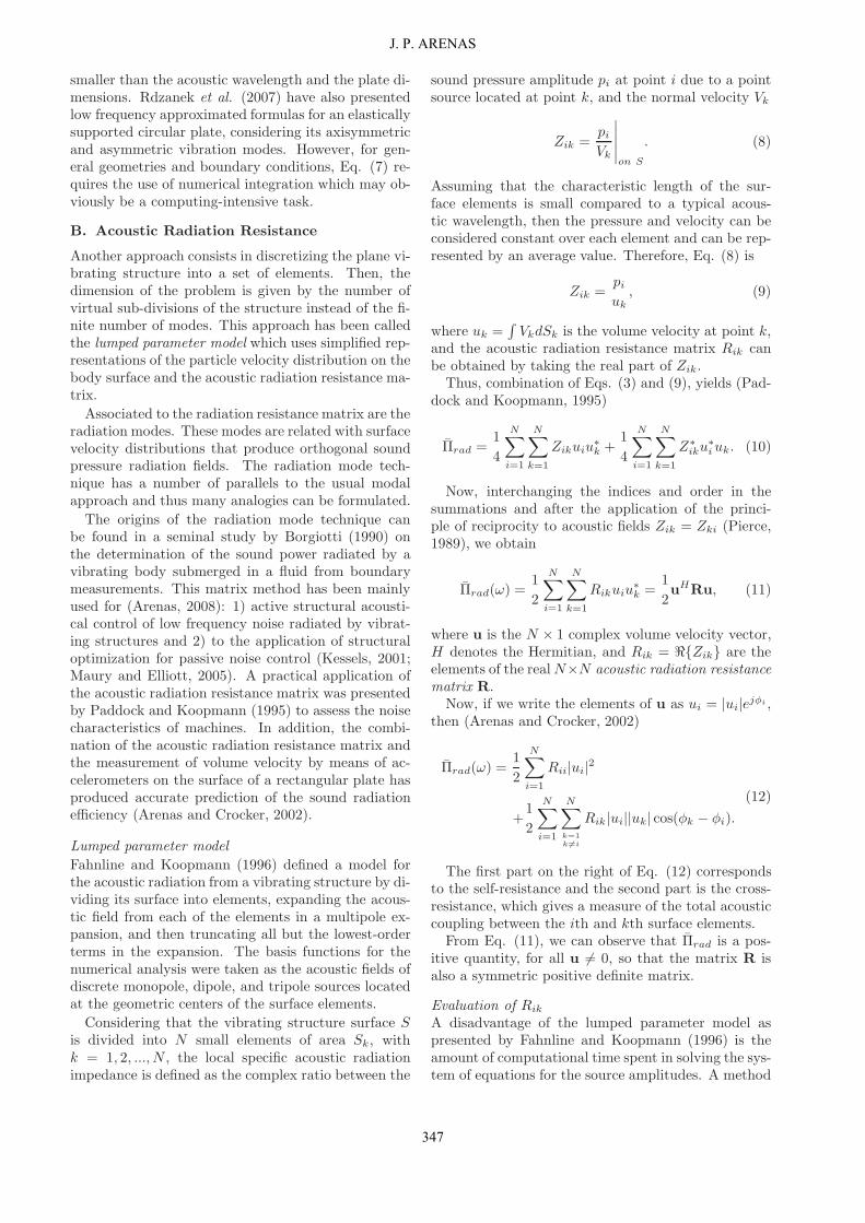
Based on Eq. (11), the sound radiation efficiency ofa simply-supported rectangular aluminum plate (E =7.1 × 10¹⁰ N/m2, ρ = 2700 kg/m3) is calculated as anexample. The plate’s surface is 0.5 × 0.6 m2 and itsthickness h = 3 mm. In addition, to excite a relativelylarge number of modes, location of a unit point excita-tion force is fixed at (x = 0.02 m, y = 0.02 m) relativeto the lower left corner, and the frequency is varied.the plate was divided into 20×20 elements (M = 400).
To give an indication of the effects of increasingplate’s internal damping, damping loss factors η = 0.1,0.2 and 0.4 were chosen. The infinite numbers ofmodes in Eq. (19) are truncated to a finite number.For this example, all modes with natural frequenciesbelow 10 kHz are included in the computation. Fig-ure 5 presents the results for sound radiation efficiencyfrom Eq. (11) as a function of frequency. As a refer-ence, the values of the frequency of the first resonancef11 and the critical frequency fc have been indicatedin Fig. 5. The radiation efficiency obtained for thefirst mode is also plotted for comparison.
101 102 103 104
10−3
10−2
10−1
100
Frequency (Hz)
Rad
iatio
n ef
ficie
ncy
σ11
η = 0.1η = 0.2η = 0.4
f11 fc
Figure 5: σrad for a simply-supported aluminum plate(0.5 × 0.6 × 0.003 m3) for different values of dampingloss factor.
Again, the results of the numerical evaluation are ingood agreement with the results presented by Xie etal. (2005) that were calculated for the same plate byusing a modal summation approach. We can observethat below 70 Hz the radiation efficiency of the firstmode determines the overall result. This is due to the
dominance of this mode in the response. Above thisfrequency the results drop, only rising to unity closeto fc of about 4 kHz.
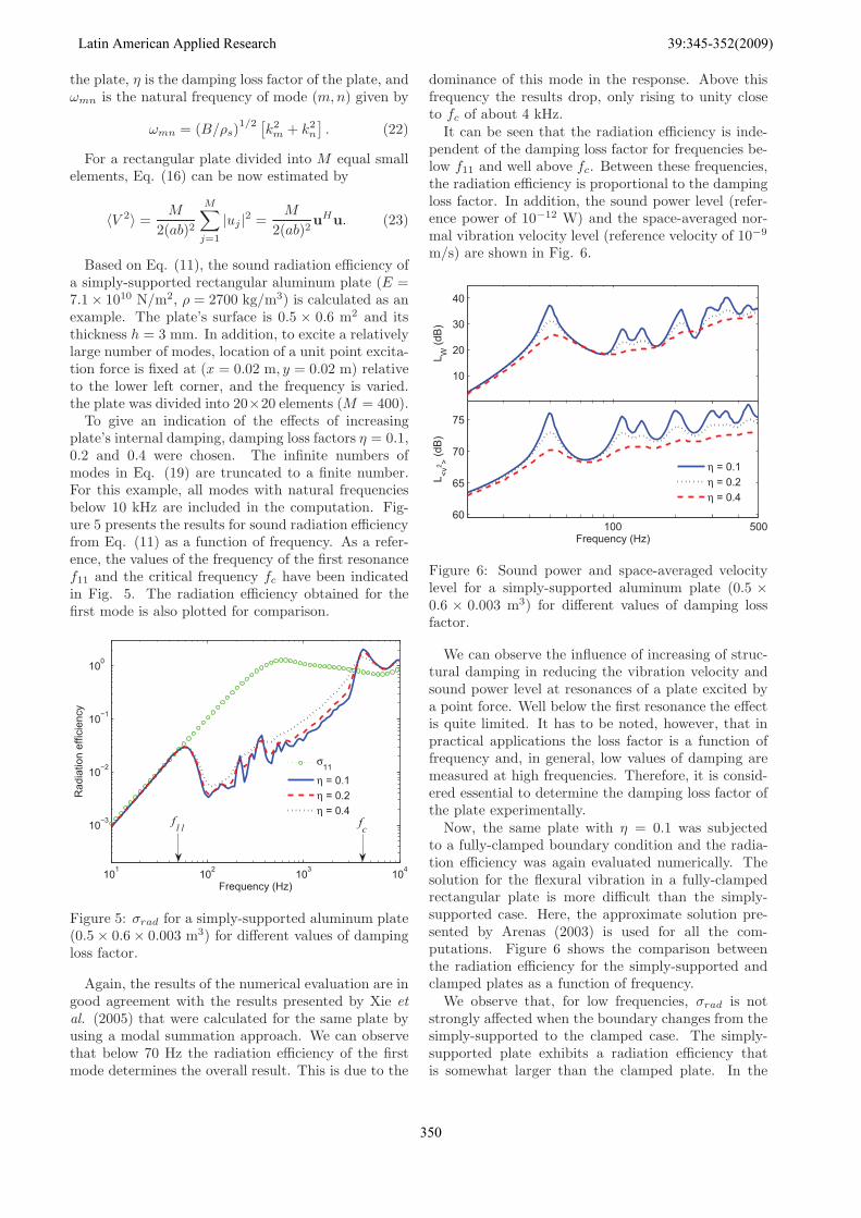
It can be seen that the radiation efficiency is inde-pendent of the damping loss factor for frequencies be-low f11 and well above fc. Between these frequencies,the radiation efficiency is proportional to the dampingloss factor. In addition, the sound power level (refer-ence power of 10−12 W) and the space-averaged nor-mal vibration velocity level (reference velocity of 10−9
m/s) are shown in Fig. 6.
10
20
30
40
L W (d
B)
100 50060
65
70
75
Frequency (Hz)
L <v2 > (d
B)
η = 0.1η = 0.2η = 0.4
Figure 6: Sound power and space-averaged velocitylevel for a simply-supported aluminum plate (0.5 ×0.6 × 0.003 m3) for different values of damping lossfactor.
We can observe the influence of increasing of struc-tural damping in reducing the vibration velocity andsound power level at resonances of a plate excited bya point force. Well below the first resonance the effectis quite limited. It has to be noted, however, that inpractical applications the loss factor is a function offrequency and, in general, low values of damping aremeasured at high frequencies. Therefore, it is consid-ered essential to determine the damping loss factor ofthe plate experimentally.
Now, the same plate with η = 0.1 was subjectedto a fully-clamped boundary condition and the radia-tion efficiency was again evaluated numerically. Thesolution for the flexural vibration in a fully-clampedrectangular plate is more difficult than the simply-supported case. Here, the approximate solution pre-sented by Arenas (2003) is used for all the com-putations. Figure 6 shows the comparison betweenthe radiation efficiency for the simply-supported andclamped plates as a function of frequency.
We observe that, for low frequencies, σrad is notstrongly affected when the boundary changes from thesimply-supported to the clamped case. The simply-supported plate exhibits a radiation efficiency thatis somewhat larger than the clamped plate. In the
Latin American Applied Research 39:345-352(2009)
350

101 102 103 104
10−3
10−2
10−1
100
Frequency (Hz)
Rad
iatio
n ef
ficie
ncy
S−SClamped
f S11 fcf C11
Figure 7: σrad for an aluminum plate (0.5×0.6×0.003m3, η = 0.1) for simply-supported and fully-clampedboundary conditions.
medium frequency range the radiation efficiency islarger in the clamped case. Close to and above fc theradiation efficiency is not considerably affected by theboundary condition. The results agree well with thoseobtained using numerical integration of the Rayleigh’sintegral (Berry and Nicolas, 1994).
In noise control engineering it is also importantto select a proper material to make a plate accept-able silent for a given force and particular geometry.Then, to give an indication of the effects of changingplate’s material, consider now an undamped simply-supported square plate of side 0.6 m and h = 6 mm,excited by an arbitrarily harmonic point force of am-plitude F = 9 N, fixed at (x = 0.02 m, y = 0.02 m)relative to the lower left corner. Consider that theplate is made of three different materials: polystyrene(E = 3.6 × 10⁹ N/m2, ρ = 1050 kg/m3, ν = 0.24),hardened glass (E = 72× 109 N/m2, ρ = 2900 kg/m3,ν = 0.24), and steel (E = 210 × 109 N/m2, ρ = 7850kg/m3, ν = 0.3). The materials are the same as theones used recently by Rdzanek et al. (2007) to modela circular hatchway. Figure 8 shows the calculatedsound power levels for low frequencies.
We observe that the polystyrene plate generates asound power level that exceeds 70 dB near its first res-onance around 30 Hz. The hardened glass and steelplates are much more silent up to 50 Hz, where thesound power level does not exceed 40 dB. We also ob-serve that the lowest vibration modes of the plates gen-erate considerable acoustic noise and the polystyreneplate is the most unfavorable choice of the three platesif low frequency noise have to be kept to a level thatwould be acceptable from a comfort aspect or designrequirement.
IV. CONCLUSIONS
This article discussed a matrix method to numericallyestimate the sound power radiated from planar vibrat-
100 20030
20
40
60
80
Frequency (Hz)
Sou
nd p
ower
leve
l LW
(dB
)
polystyreneglasssteel
Figure 8: Sound power level of a simply-supportedsquare plate (0.6 × 0.6 × 0.006 m3) made of three dif-ferent materials.
ing structures without integrating the sound pressurefield. The method, which is valid for baffled plates,has the advantage to use the resistance radiation ma-trix. This matrix does not depend on the velocitydistribution on the plate and thus can be reused forparametric studies, significantly reducing the compu-tation time. Since the method is discrete in nature,the approach is limited to frequencies in the mid andlow frequency range. The applicability of the methodto the analysis of the sound radiation from annularand rectangular plates has been demonstrated and theresults obtained reveal that the sound radiations cal-culated by this method are in good agreement withthose obtained by other authors.
It should also be pointed out that the method maybe useful to analyze more complicated vibroacousticproblems such as the sound radiated from viscoelasticor composite plates, in which the method may be com-bined with finite element approaches. This researchwork is presently underway.
V. ACKNOWLEDGMENTS
This work has been supported by CONICYT-FONDECYT under grant No 1060117.
REFERENCES
Arenas, J.P. and M.J. Crocker, “Sound radiation ef-ficiency of a baffled rectangular plate excited byharmonic point forces using its surface resistancematrix,” Int. J. of Acoust. and Vib., 7, 217–229(2002).
Arenas, J.P., “On the vibration analysis of rectangularclamped plates using the virtual work principle,” J.Sound Vib., 266, 912–918 (2003).
Arenas, J.P., “Numerical computation of the soundradiation from a planar baffled vibrating surface,”J. Comput. Acoust., 16, 321–241 (2008).
J. P. ARENAS
351

Berry, A. and J. Nicolas, “Structural acoustics andvibration behavior of complex panels,” Appl.Acoust., 43, 185–215 (1994).
Borgiotti, G.V., “The power radiated by a vibratingbody in an acoustic fluid and its determinationfrom boundary measurements,” J. Acoust. Soc.Am., 88, 1884–1893 (1990).
Fahnline, J.B. and G.H. Koopmann, “A lumped pa-rameter model for the acoustic power output froma vibrating structure,” J. Acoust. Soc. Am., 100,3539–3547 (1996).
Gerges, S.N.Y., Noise and Vibration in Vehicles (inPortuguese), NR Editora, Florianopolis (2004).
Graham, W.R., “Analytical approximations for themodal acoustic impedances of simply supported,rectangular plates,” J. Acoust. Soc. Am., 122,719–730 (2007).
Kessels, P.H.L., Engineering toolbox for structural-acoustic design. Applied to MRI scanners, Ph.D.dissertation, Technische Universiteit Eindhoven(2001).
Kirkup, S.M., “Computational solution of the acousticfield surrounding a baffled panel by the Rayleighintegral method,” Appl. Math. Modelling, 18, 403–407 (1994).
Lee, H. and R. Singh, “Acoustic radiation from out-of-plane modes of an annular disk using thin andthick plate theories,” J. Sound Vib., 282, 313–339(2005a).
Lee, H. and R. Singh, “Comparison of two analyticalmethods used to calculate sound radiation from ra-dial vibration modes of a thick annular disk,” J.Sound Vib., 285, 1210–1216 (2005b).
Li, W.L. and H.J. Gibeling, “Determination of themutual radiation resistances of a rectangular plateand their impact on the radiated sound power,” J.Sound Vib., 229, 1213–1233 (2000).
Li, W.L., “An analytical solution for the self- and mu-tual radiation resistances of a rectangular plate,”J. Sound Vib., 245, 1–16 (2001).
Maury, C. and S.J. Elliott, “Analytic solutions of theradiation modes problem and the active control ofsound power,” Proc. R. Soc. A, 461, 55–78 (2005).
Morse, P.M. and K.U. Ingard, Theoretical Acoustics,Princeton University Press, Princeton (1986).
Paddock, E.H. and G.H. Koopmann, “The use of ra-diation resistance measurements to assess the noisecharacteristics of machines,” Proc. ASME DesignEngineering Tech. Conf., Boston, USA, 655–662(1995).
Pierce, A.D., Acoustics: an Introduction to its PhysicalPrinciples and Applications, Acoustical Society ofAmerica, New York (1989).
Pierce, A.D., R.O. Cleveland and M. Zampolli, “Radi-ation impedance matrices for rectangular interfaceswithin rigid baffles: Calculation methodology andapplications,” J. Acoust. Soc. Am., 111, 672–684(2002).
Rayleigh, L.S., The Theory of Sound, Dover, New York(1945).
Rdzanek, W.P., W.J. Rdzanek, Z. Engel and K.Szemela, “The modal low frequency noise of anelastically supported circular plate,” Int. J. ofOccupational Safety and Ergonomics, 13, 147–157(2007).
Rdzanek, W.P., “The sound power radiated by someaxisymmetric vibration modes of a guided annularplate,” Int. J. of Acoust. and Vib., 8, 33–37 (2003).
Snyder, S.D. and N. Tanaka, “Calculating total acous-tic power output using modal radiation efficien-cies,” J. Acoust. Soc. Am., 97, 1702–1709 (1995).
Stepanishen, P.R., “Evaluation of mutual radiationimpedances between circular pistons by impulse re-sponse and asymptotic methods,” J. Sound Vib.,59, 221–235 (1978).
Wodtke, H.W. and J.S. Lamancusa, “Sound powerminimization of circular plates through dampinglayer placement,” J. Sound Vib., 215, 1145–1163(1998).
Xie, G., D.J. Thompson and C.J.C. Jones, “The ra-diation efficiency of baffled plates and strips,” J.Sound Vib., 280, 181–209 (2005).
Latin American Applied Research 39:345-352(2009)
352