matrix 430 - ag spray equipment
TRANSCRIPT

U S E R M A N U A LMATRIX® 430
Software version 1.04

MATRIX® 430
GU
IDA
NCE
JOB D
ATACO
NFIG
URATIO
NIN
TROD
UC
TION
CON
SOLE
ii www.teejet.com
QUICK START GUIDE
SETUP THE CONSOLE
1. On guidance screen, press NAVIGATION AND GUIDANCE OPTIONS tab to display options.
2. Press HOME button .
3. Press CONSOLE button . Adjust settings as needed. XLCD Brightness XColour Scheme XUnits
XGNSS Demo Mode XScreenshot XTime Zone
CONFIGURE THE MACHINE
4. From the Home screen , press CONFIGURATION button .
5. Select and configure a Machine profile .
XSelect Machine Profile Number A – use to select 1 of 5 machine profiles. The profile that is “active” is displayed/active on the operation screen.
XSet Number of Implement Sections B – used to select the number of implement sections. Range is 1 to 7 sections.
XSet Section Widths C – used to enter the width of each section. Each section can be a different width.
XSet Lateral Implement Offset Distance D – used to define the lateral distance from the centre line of the machine to the centre of the implement. – Positive value will move the implement to the right of centre while facing in the machine’s forward direction.
– Negative value will move the implement to the left of centre while facing in the machine’s forward direction.
XSet In-Line Implement Offset Distance E – used to define the in-line distance from the GNSS antenna (the zero point) to the implement. – Positive value will move the implement behind the GNSS antenna. – Negative value will move the implement in front of the GNSS antenna.
6. Select Lighbar Spacing – used to set the distance away from the guideline or vehicle each guidance screen lightbar box represents.
7. Set GNSS configuration .
NOTE: When using the Matrix 430 in Europe, always work with GPS and GLONASS. Use SBAS (EGNOS) where applicable.
#1
#4
#2
C
B A
D
E
#3
#5
#6
#7

MATRIX® 430
GU
IDA
NCE
JOB
DAT
ACO
NFI
GU
RATI
ON
INTR
OD
UC
TIO
NCO
NSO
LE
iii98-05332-EN R2
#1SETUP GUIDANCE
1. From the Home screen , press GUIDANCE button .
2. Establish desired Selectable Guidance Bar Information. – Speed – Total Applied Area – Application Time – Swath Number
3. On vehicle view guidance screen, from the NAVIGATION AND GUIDANCE OPTIONS tab , select Guidance mode
– Straight AB guidance
– Last pass guidance
– No guidance
– Curved AB guidance
– Circle pivot guidance
– NextRow guidance
4. On vehicle view guidance screen, from the NAVIGATION AND GUIDANCE OPTIONS tab , create boundary
5. Create AB guideline .
GUIDANCE SCREEN OPTIONS
XApplication Mapping – press VEHICLE icon in the centre of the guidance screen to turn on or off application mapping.
XReturn to Point – set a return point to provide guidance back to the established point.
XA+ Nudge Feature – allows the current guideline to be shifted to the vehicle’s current location. XTransport Mode / – recommended for use when traveling between fields as this will improve accuracy in guidance functions.
#2
Statu
s Bar
Guidance Bar
Coverage Area WBlues – one application WReds – two or more applications
Vehicle with real-time representation of active boom sections
WEmpty box – inactive section WWhite box – active section
Navigation and Guidance Options Tab
Navigation Guidelines WOrange – active guidance line WBrown – two guidance lines adjacent to the left and right of the active guideline
#3
#4
#5

MATRIX® 430
GU
IDA
NCE
JOB D
ATACO
NFIG
URATIO
NIN
TROD
UC
TION
CON
SOLE
iv www.teejet.com
Table of contentsQUICK START GUIDE IISETUP THE CONSOLE II
CONFIGURE THE MACHINE II
SETUP GUIDANCE III
GUIDANCE SCREEN OPTIONS III
IMPORTANT SAFETY INFORMATION VIGENERAL WARNINGS AND PRECAUTIONS VI
CHAPTER 1 – INTRODUCTION 1SYSTEM COMPONENTS 1
Matrix 430 Console ........................................................................................................................................................................................1System Components .....................................................................................................................................................................................1
Recommended Antenna Installation ..........................................................................................................................1POWER 2
BASIC SCREEN USE 2Home Screen ....................................................................................................................................................................................................2Keyboard Entry Screens ...............................................................................................................................................................................3Options Menus ................................................................................................................................................................................................3
ICON REFERENCE 3
CHAPTER 2 – GUIDANCE 5GUIDANCE SCREEN OPTIONS AND INFORMATION 5
Guidance Views ...............................................................................................................................................................................................5Vehicle View Navigation ............................................................................................................................................5Field View Navigation ................................................................................................................................................6
Guidance Bar ....................................................................................................................................................................................................6Transport Mode ...............................................................................................................................................................................................7Guidelines..........................................................................................................................................................................................................7
Marking A and B Points .............................................................................................................................................7A+ Nudge Feature .....................................................................................................................................................8
NextRow .............................................................................................................................................................................................................8Status Bar ...........................................................................................................................................................................................................9
NAVIGATION AND GUIDANCE OPTIONS TAB 10Guidance Modes .......................................................................................................................................................................................... 11Application Boundary ................................................................................................................................................................................ 12
Creating a Boundary ...............................................................................................................................................12Delete the Boundary................................................................................................................................................13
Return to Point.............................................................................................................................................................................................. 13Marking a Return Point ............................................................................................................................................13Guidance to a Return Point .....................................................................................................................................13Delete the return point .............................................................................................................................................14
Zoom In/Out .................................................................................................................................................................................................. 14Pan .................................................................................................................................................................................................................... 14
MATRIX® 430
GU
IDA
NCE
JOB
DAT
ACO
NFI
GU
RATI
ON
INTR
OD
UC
TIO
NCO
NSO
LE
v98-05332-EN R2
APPLICATION MAPPING & APPLIED ALERT 15Mapping with Console Only .....................................................................................................................................15Mapping with Work On/Off Switch ...........................................................................................................................15Applied Alert ............................................................................................................................................................15
CHAPTER 3 – CONFIGURATION 16Machine Configuration .............................................................................................................................................................................. 16Lightbar Spacing .......................................................................................................................................................................................... 17GNSS Receiver Configuration .................................................................................................................................................................. 17
CHAPTER 4 – JOB DATA 18Job Data Overview ..................................................................................................................................................18Delete Job Data ......................................................................................................................................................18Reports ...................................................................................................................................................................19
Memory Notifications ................................................................................................................................................................................ 19
CHAPTER 5 – CONSOLE 20
Copyrights© 2019 TeeJet Technologies. All rights reserved. No part of this document or the computer programmes described in it may be reproduced, copied, photocopied, translated, or reduced in any form or by any means, electronic or machine readable, recording or otherwise, without prior written consent from TeeJet Technologies.
TrademarksUnless otherwise noted, all other brand or product names are trademarks or registered trademarks of their respective companies or organisations.
Limitation of LiabilityTEEJET TECHNOLOGIES PROVIDES THIS MATERIAL “AS IS” WITHOUT WARRANTY OF ANY KIND, EITHER EXPRESSED OR IMPLIED. NO COPYRIGHT LIABILITY OR PATENT IS ASSUMED. IN NO EVENT SHALL TEEJET TECHNOLOGIES BE LIABLE FOR ANY LOSS OF BUSINESS, LOSS OF PROFIT, LOSS OF USE OR DATA, INTERRUPTION OF BUSINESS, OR FOR INDIRECT, SPECIAL, INCIDENTAL, OR CONSEQUENTIAL DAMAGES OF ANY KIND, EVEN IF TEEJET TECHNOLOGIES HAS BEEN ADVISED OF SUCH DAMAGES ARISING FROM TEEJET TECHNOLOGIES SOFTWARE.
TeeJet® Technologies
www.teejet.com
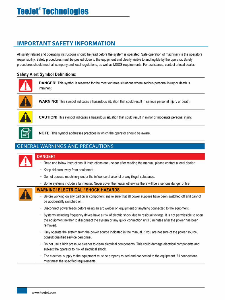
IMPORTANT SAFETY INFORMATION
All safety related and operating instructions should be read before the system is operated. Safe operation of machinery is the operators responsibility. Safety procedures must be posted close to the equipment and clearly visible to and legible by the operator. Safety procedures should meet all company and local regulations, as well as MSDS-requirements. For assistance, contact a local dealer.
Safety Alert Symbol Definitions:
DANGER! This symbol is reserved for the most extreme situations where serious personal injury or death is imminent.
WARNING! This symbol indicates a hazardous situation that could result in serious personal injury or death.
CAUTION! This symbol indicates a hazardous situation that could result in minor or moderate personal injury.
NOTE: This symbol addresses practices in which the operator should be aware.
GENERAL WARNINGS AND PRECAUTIONS
DANGER!• Read and follow instructions. If instructions are unclear after reading the manual, please contact a local dealer.
• Keep children away from equipment.
• Do not operate machinery under the influence of alcohol or any illegal substance.
• Some systems include a fan heater. Never cover the heater otherwise there will be a serious danger of fire!
WARNING! ELECTRICAL / SHOCK HAZARDS• Before working on any particular component, make sure that all power supplies have been switched off and cannot
be accidentally switched on.
• Disconnect power leads before using an arc welder on equipment or anything connected to the equpment.
• Systems including frequency drives have a risk of electric shock due to residual voltage. It is not permissible to open the equipment neither to disconnect the system or any quick connection until 5 minutes after the power has been removed.
• Only operate the system from the power source indicated in the manual. If you are not sure of the power source, consult qualified service personnel.
• Do not use a high pressure cleaner to clean electrical components. This could damage electrical components and subject the operator to risk of electrical shock.
• The electrical supply to the equipment must be properly routed and connected to the equipment. All connections must meet the specified requirements.

TeeJet® Technologies
98-01556-EN R0
WARNING! PRESSURISED HYDRAULIC SYSTEMS• Always wear personal protective equipment (PPE) when performing work on hydraulic systems.
• Adhere to the machine manufacture’s approved maintenance instructions when working on the hydraulic system.
• Always turn equipment off when working on the hydraulic system. Take appropriate precautions when opening systems that have been previously pressurised.
• Be aware that hydraulic oil may be extremely hot and under high pressure.
WARNING! CHEMICAL HANDLING• Always wear PPE when handling any chemical substance.
• Always follow safety labels and instructions provided by the chemical manufacturer or supplier.
• The operator should have full information on the nature and the quantity of the material to be distributed.
• ADHERE TO FEDERAL, STATE AND LOCAL REGULATIONS REGARDING THE HANDLING, USE OR DISPOSAL OF AGRICULTURAL CHEMICALS.
WARNING! PRESSURISED SPRAY SYSTEM• It is important to recognise proper safety precautions when using a pressurised spray system. Fluids under pressure
can penetrate skin and cause serious personal injury.
• The system pressure should never exceed the lowest rated component. Always know your system and all component capabilities, maximum pressures and flow rates.
• Filters can only be opened when the manual valves in front of and behind the filter are in closed position. If any appliance has to be taken out of the piping, manual valves in front of and behind this appliance have to be in closed position. If they are reinstalled, make sure that this happens correctly, that this apparatus is well aligned, and that all connections are tight.
• The plumbing supply to the equipment should meet all company and local regulations and must be properly routed and connected to the equipment. All connections must meet the specified requirements.
• It is advised to drain and purge the liquid train when the equipment shall not be used for a longer period of time.
WARNING! AUTO STEERING SAFETY• To prevent serious personal injury or death from being run over by the vehicle or automated motion of the steering
system, never leave the vehicles operator seat with the system engaged.
• To prevent serious personal injury or death from being run over by the vehicle or automated motion of the steering system, verify the area around the vehicle is clear of people or obstacles before startup, calibration, tuning or engaging the system.
• Make sure equipment is tightly secured to the proper components.
• Never drive on public roads with system engaged.
CAUTION! EQUIPMENT SAFETY, MAINTENANCE, AND SERVICE• The equipment should be operated only by properly trained, qualified personnel. They must have proven their skills
in the operation of the equipment.
• Before using the equipment, the operator has to check if the equipment is in good condition and can be used safely. If not, the equipment cannot be used.
• All necessary PPE must be readily available to the operator at all times.
• Routinely check the system and components for wear and damage. Replace or repair when necessary.
• Only qualified authorised experts are allowed to repair or maintain the installation. The maintenance and operating instructions shall be rigidly observed and followed.
• A complete manual for the equipment must be available to the operator or maintenance technician at all times.

TeeJet® Technologies
www.teejet.com
CAUTION! HARNESS CABLE AND HOSE SAFETY• Routinely check all harness cables and hoses for damage or wear. Replace or repair when necessary.
• Do not route harness cables and hoses with sharp bends.
• Do not strap harness cables and hoses to lines with high vibration or spikes in pressure.
• Do not strap harness cables and hoses to lines transporting hot fluids.
• Protect harness cables and hoses from sharp objects, equipment debris, and material buildup.
• Allow sufficient length for harness cables and hoses to have free movement on sections that move during operation, and be sure that harness cables or hoses do not hang below the equipment.
• Allow sufficient clearance for harness cables and hoses from implement and machine operational zones.
• When cleaning equipment, protect harness cables from high pressure wash.
NOTE: TOUCH SCREEN CARE• Keep sharp objects away from the touch screen device. Touching the screen with a sharp object could result in
damage to the display.
• Do not use harsh chemicals to clean the console/display. The correct way to clean a console/display is to use a soft damp cloth or anti-static wipe, similar to cleaning a monitor on a computer.
NOTE: RECOMMENDED REPLACEMENT PARTS• The system has been designed with components that work together to provide the best system performance. When
the system requires replacement parts, only TeeJet recommended components should be used to maintain proper system operation and safety.

MATRIX® 430
GU
IDA
NCE
JOB
DAT
ACO
NFI
GU
RATI
ON
CON
SOLE
198-05332-EN R2
INTR
OD
UC
TIO
N
CHAPTER 1 – INTRODUCTION
SYSTEM COMPONENTS
Matrix 430 ConsoleThe console is designed to provide years of service under typical agricultural operating conditions. A tight fitting enclosure, combined with rubber covers for all connectors means that typical dusty environments will not cause operational problems. While occasional splashing of water will not damage the unit, the console is not designed for direct exposure to rain. Take care not to operate the console in wet conditions.
GNSS Antenna connection
Power connection
Integrated RAM Mount (assembly required)
Power button
USB Port with rubber cover
Standard RAM Bracket(assembly required)
Bright Touch Screen
System Components
Connect +12v at 15/30Connect GND to 31
Power Cable45-05867DC:xx/xx
Console, Matrix 430 CG430-GLO
Kit, RAM Mount w/ Suction Cup
Power Cable45-05645DC:xx/xx
Connect to+12v Only
POWER CABLE45-05775DC: XXXX
CAUTION CONN. TO+12V ONLY
GPS Patch Antenna
RXA-30 Antenna
Power Cables
Power/Sense/Speed Cables
Direct to Battery 45-05775
Lighter Adapter 45-05645
US 45-05970
EU 45-05969
COBO Adapter 45-05867
Status On/OffSENSE
+12v
GPS Speed
POWER IN
Power/Sense/Speed
45-05970 xx/xx
Power/Sense/Speed
45-05969 xx/xx
POWER IN
Work On-Off
GPS Speed
The console needs to be cycled off and back on when changing or attaching equipment to the Matrix 430 system.
Recommended Antenna InstallationThe GNSS antenna should be mounted as far forward as possible on top of the cab on a metal surface of at least 4”/10 cm square.

MATRIX® 430
GU
IDA
NCE
JOB D
ATACO
NFIG
URATIO
NCO
NSO
LE
2 www.teejet.com
INTRO
DU
CTIO
N
POWER
Power On1. Press POWER button .
Power Off1. Press POWER button .
2. Select from: XAccept – to continue shut down XCancel – to keep the console on.
WARNING! Wait 30 seconds before restarting the console after powering off.
BASIC SCREEN USE
The basic screen functions are:• Home button accesses the Home screen with setup buttons
for Guidance, Configuration, Job Data, Console settings and a calculator
• Options tab on the Guidance screen accesses the Home button and navigation options
• Warnings and information pop-ups inform of console activities and details on configuration or application functions
• Configuration options can be applied using option menus or keyboard entry screens
NOTE: When application is active, some configuration options are unavailable.
Home ScreenThe Home screen gives access to guidance, configuration, job data and a calculator.
Guidance Used to view a computer-generated image of the vehicle position displayed in the application area. From this screen all setup and navigation options can be accessed via the tab on the right side of the screen.
Configuration Used to select and setup the machine configurations, lightbar configurations and GNSS receiver.
Job Data Used to select current job, view or delete job data and export reports.
Console Used to setup LCD brightness, colour scheme, units, screenshot and time zone; start demonstration GNSS; and view console information.
Calculator

MATRIX® 430
GU
IDA
NCE
JOB
DAT
ACO
NFI
GU
RATI
ON
CON
SOLE
398-05332-EN R2
INTR
OD
UC
TIO
N
Keyboard Entry ScreensSome screens offer keyboard entry. Press the current selection to access the keyboard. Use the numeric keypad to enter a value.
To change a value:
1. Press CURRENT VALUE.
2. Use the numeric keypad to enter a new value.
3. Select from: XAccept – to save the settings XCancel – to leave the keypad without saving
(m)
1 2 3
1.50
Clear
4 5 6 <--
7 8 9
0 . +/-
Options MenusPress the current selection to access options. Select an appropriate option, or use a next page arrow to access additional options. To close the list without changing the current option, select the current option.
To change a value:
1. Press CURRENT VALUE.
2. Select an appropriate option.
3322
55
11
44
ICON REFERENCE
Guidance
Selectable Information
Speed
Total Applied Area
Application Time
Swath Number
Show nothing
Mark A , Mark B
A+ Nudge Feature
Transport Mode / Work Mode
Navigation and Guidance Options tab
Home
Guidance Modes
Straight AB guidance
Last pass guidance
No guidance
Curved AB guidance
Circle pivot guidance
NextRow guidanceApplication Boundary
Start
Finish
Cancel
DeleteReturn to Point
Mark
Go to point
Cancel
Delete
Close Options
Field View
Vehicle View
Pan
Zoom In/Out

MATRIX® 430
GU
IDA
NCE
JOB D
ATACO
NFIG
URATIO
NCO
NSO
LE
4 www.teejet.com
INTRO
DU
CTIO
N
Configuration
Machine Configuration
Machine Profile Number
Number of Implement Sections
Section Widths
Lateral Implement Offset Distance
In-Line Implement Offset Distance
Lightbar spacing
GNSS Receiver Configuration
Job Data
Total Applied Area
Bounded Area
Application Time
Delete
Reports
Console
LCD Brightness
User Interface Colour Scheme
Units
Demonstration GNSS: GNSS or Demo
Screenshot
Time Zone
About

MATRIX® 430
JOB
DAT
ACO
NFI
GU
RATI
ON
INTR
OD
UC
TIO
NCO
NSO
LE
598-05332-EN R2
GU
IDA
NCE
CHAPTER 2 – GUIDANCE
Two guidance screens, vehicle view and field view, assist in keeping the user informed. From the vehicle view screen, guidance setup and navigation options can be accessed via the tab on the right side of the screen.
GUIDANCE SCREEN OPTIONS AND INFORMATION
Guidance Views
Vehicle View NavigationVehicle view guidance creates a computer-generated image of the vehicle position displayed in the application area.
Statu
s Bar
Guidance Bar
Painted Coverage AreaOverlap Coverage Area
Vehicle with real-time representation of active boom sections
Navigation and Guidance Options Tab
Navigation Guidelines
On Screen Guidance• Guidelines:
WOrange – active guidance line WBrown – two guidance lines adjacent to the left and right of the active guideline WDark grey – boundary line
• Points – markers for established points: WRed point – Return to point WBlue point – Mark A WGreen point – Mark B
• Coverage Area – illustrates applied area and overlap: WBlue – one application WRed – two or more applications
Zoom in/out & perspective – adjusts the vehicle’s view or perspective to the horizon from vehicle view to bird’s eye view.
• Boom Sections: WEmpty box – inactive section WWhite box – active section
MATRIX® 430
JOB D
ATACO
NFIG
URATIO
NIN
TROD
UC
TION
CON
SOLE
6 www.teejet.com
GU
IDA
NCE
Field View NavigationField view guidance creates a computer-generated image of vehicle position and application area from an aerial perspective.
Painted Coverage Area
Overlap Coverage Area
Vehicle
Navigation and Guidance Options Tab
Boundary
On Screen Guidance• Guidelines:
WDark grey – boundary line• Coverage Area – illustrates applied area and overlap:
WBlue – one application WRed – two or more applications
• Points – markers for established points: WRed point – Return to point WBlue point – Mark A WGreen point – Mark B
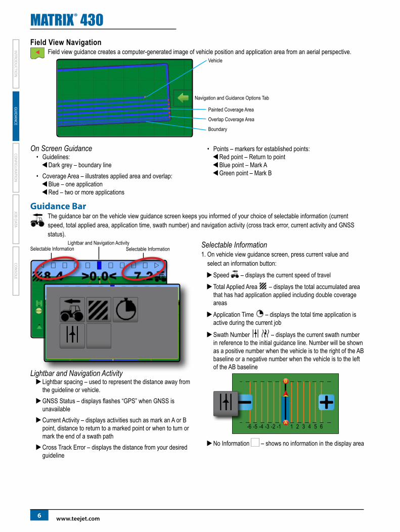
Guidance Bar The guidance bar on the vehicle view guidance screen keeps you informed of your choice of selectable information (current speed, total applied area, application time, swath number) and navigation activity (cross track error, current activity and GNSS status).
Lightbar and Navigation ActivitySelectable Information Selectable Information
Lightbar and Navigation Activity XLightbar spacing – used to represent the distance away from the guideline or vehicle. XGNSS Status – displays flashes “GPS” when GNSS is unavailable XCurrent Activity – displays activities such as mark an A or B point, distance to return to a marked point or when to turn or mark the end of a swath path XCross Track Error – displays the distance from your desired guideline
Selectable Information1. On vehicle view guidance screen, press current value and
select an information button: XSpeed – displays the current speed of travel XTotal Applied Area – displays the total accumulated area that has had application applied including double coverage areas XApplication Time – displays the total time application is active during the current job
XSwath Number – displays the current swath number in reference to the initial guidance line. Number will be shown as a positive number when the vehicle is to the right of the AB baseline or a negative number when the vehicle is to the left of the AB baseline
1 2 3 4 5 6-6 -5 -4 -3 -2 -1
XNo Information – shows no information in the display area

MATRIX® 430
JOB
DAT
ACO
NFI
GU
RATI
ON
INTR
OD
UC
TIO
NCO
NSO
LE
798-05332-EN R2
GU
IDA
NCE
Status Bar The status bar provides information on GNSS status, guidance mode, boundary area, and implement control status.
GNSS Status
Guidance Mode
Bounded Area Status
Application Mapping Status
GNSS StatusRed = no GNSS
GPS only
Green = DGPS,WAAS/RTK, GLONASS
Guidance ModeStraight AB guidance
Last pass guidance
No icon = no guidance
Curved AB guidance
Circle pivot guidance
NextRow guidance
Bounded Area StatusOutside Boundary = currently traveling outside bounded area
Inside Boundary = currently traveling inside bounded area
No icon = no boundary established
Application Mapping Status Red = off
Green = on
Status/Information ScreensTo display information:
1. On vehicle view guidance screen, press status bar icon. XGNSS Status – displays information regarding number of satellites in view, satellite quality and receiver ID
XBounded Area Status – displays information regarding the area in the current boundary
To remove the information box, tap the information box.
MATRIX® 430
JOB D
ATACO
NFIG
URATIO
NIN
TROD
UC
TION
CON
SOLE
8 www.teejet.com
GU
IDA
NCE
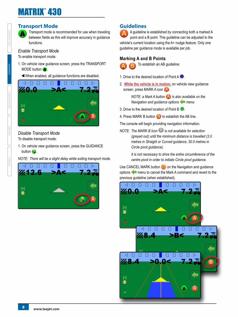
Transport Mode Transport mode is recommended for use when traveling between fields as this will improve accuracy in guidance functions.
Enable Transport Mode To enable transport mode:
1. On vehicle view guidance screen, press the TRANSPORT MODE button .
WWhen enabled, all guidance functions are disabled.
Disable Transport Mode To disable transport mode:
1. On vehicle view guidance screen, press the GUIDANCE button .
NOTE: There will be a slight delay while exiting transport mode.
GuidelinesA guideline is established by connecting both a marked A point and a B point. This guideline can be adjusted to the
vehicle’s current location using the A+ nudge feature. Only one guideline per guidance mode is available per job.
Marking A and B PointsTo establish an AB guideline:
1. Drive to the desired location of Point A .
2. While the vehicle is in motion, on vehicle view guidance screen, press MARK A icon .
NOTE: a Mark A button is also available on the Navigation and guidance options menu
3. Drive to the desired location of Point B .
4. Press MARK B button to establish the AB line.
The console will begin providing navigation information.
NOTE: The MARK B Icon is not available for selection (greyed out) until the minimum distance is travelled (3.0 metres in Straight or Curved guidance, 50.0 metres in Circle pivot guidance).
It is not necessary to drive the entire circumference of the centre pivot in order to initiate Circle pivot guidance.
Use CANCEL MARK button on the Navigation and guidance options menu to cancel the Mark A command and revert to the previous guideline (when established).

MATRIX® 430
JOB
DAT
ACO
NFI
GU
RATI
ON
INTR
OD
UC
TIO
NCO
NSO
LE
998-05332-EN R2
GU
IDA
NCE
A+ Nudge FeatureThe A+ nudge feature allows the current guideline to be shifted to the vehicle’s current location.
To adjust the guideline:
1. On vehicle view guidance screen, press A+ NUDGE button .
NOTE: An A+ Nudge button is also available on the Navigation and guidance options menu.
NextRowNextRow guidance indicates where the NextRow is located based on the working width (section width × number of
sections), and provides manual guidance information at user-marked end of a row to the next adjacent row. When the operator signals the end of the row, a Straight AB line will be established in the current row and guidance will be provided to the next row. Once the vehicle has entered into the next row, no guidance or guidelines are shown.
To activate NextRow guidelines:
1. At the end of a row (while driving a straight line) on vehicle view guidance screen, press MARK B icon .
WThe end of the row will be marked with a green point . WThe navigation information will change to < < < > > > to indicate it is time to turn.
2. Turn toward the next row.
3. Based on that direction turned, guidance will be provided for the next adjacent row.
WWhen the vehicle is in the row, the guideline is removed. WThe navigation information will change to > > > < < < to indicate it is time to again mark the end of the row.
4. Repeat at the end of the next row.
NOTE: The NextRow guidance feature does not support skipping rows.

MATRIX® 430
JOB D
ATACO
NFIG
URATIO
NIN
TROD
UC
TION
CON
SOLE
10 www.teejet.com
GU
IDA
NCE
NAVIGATION AND GUIDANCE OPTIONS TAB
The Navigation and Guidance Options Tab is always available on the Guidance screen. This tab accesses the menu with the Home button, guidance modes and navigation options.
Vehicle ViewNavigation and Guidance Options Tab Menu Buttons
Home – used to access Home screen
Guidance Views – used to change between Vehicle View and Field View
Guidance Modes – used to change guidance mode:
Straight AB guidance Curved AB guidance
Last Pass guidance Circle Pivot guidance
No guidance NextRow guidance
Application Boundary – used to create or delete a boundary
Start Creating Boundary Cancel Boundary Creation
Finish Boundary Creation Delete Boundary
Return to Point – used to create, guide to or delete a point
Mark Point Cancel Navigation
Go to Point Delete Point
Zoom In/Out – slidebar icons increase/decrease the area displayed on the screen
Mark A Point – used to establish the first point in an AB guideline
Close Menu – used to close the Navigation and guidance options menu
Field ViewNavigation and guidance options tab menu buttons
Home – used to access Home screen
Guidance views – used to change between Vehicle view and Field view
Pan – used to move the displayed map area in the corresponding direction without moving the vehicle
Zoom in/out – slidebar icons increase/decrease the area displayed on the screen
Close menu – used to close the Navigation and guidance options menu

MATRIX® 430
JOB
DAT
ACO
NFI
GU
RATI
ON
INTR
OD
UC
TIO
NCO
NSO
LE
1198-05332-EN R2
GU
IDA
NCE
Guidance ModesThe guidance modes button is used to change the guidance mode.
To choose a guidance mode:
1. On vehicle view guidance screen, press NAVIGATION AND GUIDANCE OPTIONS tab to display navigation options.
2. Press GUIDANCE MODE button .
3. Select from: XStraight AB guidance
XLast pass guidance
XNo guidance XCurved AB guidance XCircle pivot guidance XNextRow guidance
NOTE: Offset to adjacent guidelines will be calculated using the working width: see “Configuration -> Machine Configuration ” in the Configuration chapter.
Straight AB guidanceStraight AB guidance provides straight line guidance based on A and B reference points. The original A and B point are used to calculate all other parallel guidelines.
Last pass guidanceLast pass guidance offers true last pass navigation. The console will automatically detect the nearest applied area and establish parallel guideline based on that area.
NOTE: If a boundary is established but no application occurred during the boundary process, guidance will not initiate.
No guidanceNo guidance turns off guidance.
NOTE: No guidance mode does not delete an established guideline or point from the console. To delete established/saved data from the console, please refer to the Job Data chapter.
Curved AB guidanceCurved AB guidance provides guidance along curved lines based on an initial AB reference line. This initial baseline is used to calculate all other guidelines.
NOTE: Curved guidance is recommended not to exceed 30° within the AB guideline.
HINT: While working in a bounded area, the guidance pattern extending beyond the established AB points will be straight line guidance.
MATRIX® 430
JOB D
ATACO
NFIG
URATIO
NIN
TROD
UC
TION
CON
SOLE
12 www.teejet.com
GU
IDA
NCE
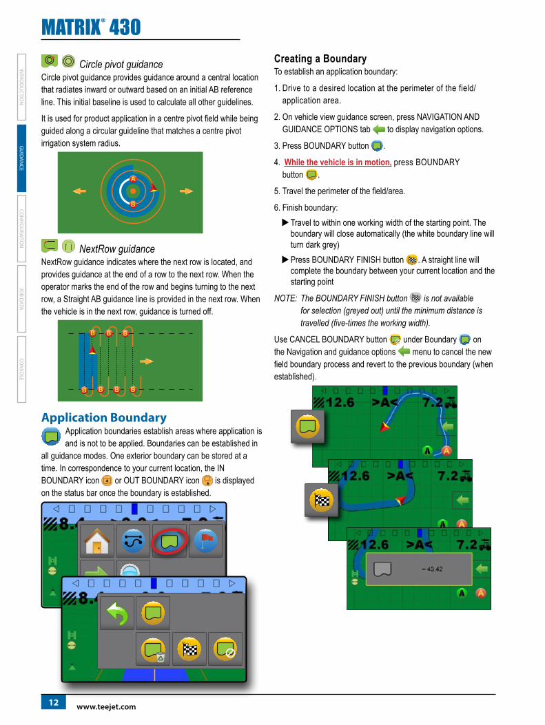
Circle pivot guidanceCircle pivot guidance provides guidance around a central location that radiates inward or outward based on an initial AB reference line. This initial baseline is used to calculate all other guidelines.
It is used for product application in a centre pivot field while being guided along a circular guideline that matches a centre pivot irrigation system radius.
NextRow guidanceNextRow guidance indicates where the next row is located, and provides guidance at the end of a row to the next row. When the operator marks the end of the row and begins turning to the next row, a Straight AB guidance line is provided in the next row. When the vehicle is in the next row, guidance is turned off.
Application BoundaryApplication boundaries establish areas where application is and is not to be applied. Boundaries can be established in
all guidance modes. One exterior boundary can be stored at a time. In correspondence to your current location, the IN BOUNDARY icon or OUT BOUNDARY icon is displayed on the status bar once the boundary is established.
Creating a BoundaryTo establish an application boundary:
1. Drive to a desired location at the perimeter of the field/application area.
2. On vehicle view guidance screen, press NAVIGATION AND GUIDANCE OPTIONS tab to display navigation options.
3. Press BOUNDARY button .
4. While the vehicle is in motion, press BOUNDARY button .
5. Travel the perimeter of the field/area.
6. Finish boundary: XTravel to within one working width of the starting point. The boundary will close automatically (the white boundary line will turn dark grey) XPress BOUNDARY FINISH button . A straight line will complete the boundary between your current location and the starting point
NOTE: The BOUNDARY FINISH button is not available for selection (greyed out) until the minimum distance is travelled (five-times the working width).
Use CANCEL BOUNDARY button under Boundary on the Navigation and guidance options menu to cancel the new field boundary process and revert to the previous boundary (when established).

MATRIX® 430
JOB
DAT
ACO
NFI
GU
RATI
ON
INTR
OD
UC
TIO
NCO
NSO
LE
1398-05332-EN R2
GU
IDA
NCE
Delete the BoundaryTo delete the established boundary:
1. On vehicle view guidance screen, press NAVIGATION AND GUIDANCE OPTIONS tab to display navigation options.
2. Press BOUNDARY button .
3. Press DELETE BOUNDARY button .
Return to Point Return to point provides guidance back to an established point. An arrow directs the vehicle back to the established point.
A return point will remain active until deleted.
Marking a Return PointTo mark a return point:
1. Drive to the desired location of return point .
2. On vehicle view guidance screen, press NAVIGATION AND GUIDANCE OPTIONS tab to display navigation options.
3. Press RETURN TO POINT button .
4. Press ADD POINT button .
Guidance to a Return PointTo show distance and guidance to the established return point:
1. On vehicle view guidance screen, press NAVIGATION AND GUIDANCE OPTIONS tab to display navigation options.
2. Press RETURN TO POINT button .
3. Press RETURN TO POINT GUIDANCE button .
The console will begin providing the distance information on the guidance bar from the vehicle to the established point.
Use CANCEL RETURN TO POINT GUIDANCE button under Return to point on the Navigation and guidance options menu to hide distance and guidance to the established point.
Guidance cannot be calculated when “?” appears in the guidance bar.

MATRIX® 430
JOB D
ATACO
NFIG
URATIO
NIN
TROD
UC
TION
CON
SOLE
14 www.teejet.com
GU
IDA
NCE
Delete the return pointTo delete the established return point:
1. On vehicle view guidance screen, press NAVIGATION AND GUIDANCE OPTIONS tab to display navigation options.
2. Press RETURN TO POINT button .
3. Press DELETE POINT button .
Delete point button is not available while return to point guidance is active.
Zoom In/OutZoom in/out is used to adjust the map’s visible area.
Vehicle View XZoom in will adjust view to vehicle view displaying a compass on the horizon
XZoom out will adjust view to bird’s eye view
NOTE: Press & hold PLUS/MINUS to quickly adjust settings.
Field View XZoom in will decrease the amount of map area visible
XZoom out will increase the amount of map area visible
NOTE: Press & hold PLUS/MINUS to quickly adjust settings.
PanWhile in Field view guidance, the Pan mode allows the screen to be positioned manually as desired.
To enter Pan mode and pan across the screen:
1. On field view guidance screen, press NAVIGATION AND GUIDANCE OPTIONS tab to display navigation options.
2. Press PAN button .
3. Press: XAND DRAG SCREEN in the corresponding direction to move the view on screen (only available if application has been applied). XARROWS in the corresponding direction to move the view on screen (down, left, right, up).
NOTE: Press & hold ARROWS to quickly adjust settings.

MATRIX® 430
JOB
DAT
ACO
NFI
GU
RATI
ON
INTR
OD
UC
TIO
NCO
NSO
LE
1598-05332-EN R2
GU
IDA
NCE
APPLICATION MAPPING & APPLIED ALERT
Application mapping is used to map coverage areas and flash and sound alerts when entering and existing
previously mapped applied areas to alert the operator to turn on or shut off application.
NOTE: Application mapping does not control actual application.
Mapping with Console OnlyTo switch mapping and alerts off or on using the console:
1. Press vehicle in the centre of the screen. WMapping and alerts on – status bar icon will change to green WMapping and alerts off – status bar icon will change to red
Mapping with Work On/Off SwitchWhen installed, the work on/off switch should remain in the “off” position for all setup options.
To switch mapping and alerts off or on using the switch:
1. Turn the switch to the “On” or “Off” position. WMapping and alerts on – status bar icon will change to green WMapping and alerts off – status bar icon will change to red
To switch mapping and alerts off or on using the console while a switch is attached:
1. Turn the switch to the “Off” position.
2. Press vehicle in the centre of the screen. WMapping and alerts on – status bar icon will change to green WMapping and alerts off – status bar icon will change to red
Applied AlertWhen entering or exiting an applied area, an audio alert will sound and section indicators will flash as each section needs to be turned on/off.
WTwo beeps – entering an applied area; section mapping will turn off WOne beep – exiting an applied area; section mapping will turn on

MATRIX® 430
GU
IDA
NCE
JOB D
ATAIN
TROD
UC
TION
CON
SOLE
16 www.teejet.com
CON
FIGU
RATION
CHAPTER 3 – CONFIGURATION
Used to select, setup and manage the machine configurations, field configurations and GNSS receiver.
Machine ConfigurationMachine configuration menu is used to create and manage up to five (5) individual machine profiles representing the
configuration of the console on a particular vehicle/equipment setup. Each machine profile records the settings in use at the time the profile is generated allowing the customer to recall their exact setup for later use.
1. From the Home screen, press CONFIGURATION button .
2. Press MACHINE CONFIGURATION button .
3. Configure each option in the following order. Press current value then use the keyboard to enter a new value or select an option from the list provided.
XMachine Profile Number – used to select one of five (5) machine profiles. The profile that is “active” is displayed/active on the operation screen.
XNumber of Implement Sections – used to select the number of implement sections. Range is 1 to 7 sections.
XSection Widths – used to enter the width of each section. Each section can be a different width. Range for each section is 1.0 to 246.1 feet / 0.30 to 75.0 metres. Total for all sections must be greater than 1.0 foot / 0.3 metres.
X
3322
55
11
44

MATRIX® 430
GU
IDA
NCE
JOB
DAT
AIN
TRO
DU
CTI
ON
CON
SOLE
1798-05332-EN R2
CON
FIG
URA
TIO
N
XLateral implement offset distance – used to define the lateral distance from the centre line of the machine to the centre of the implement. Range is 0.0 to +/-16.4 feet / 0.0 to +/-5.0 metres.
WPositive Offset Value – moves the implement to the right of centre while facing in the machine’s forward direction. WNegative Offset Value – moves the implement to the left of centre while facing in the machine’s forward direction.
X In-Line Implement Offset Distance – used to define the in-line distance from the GNSS antenna to the implement. The GNSS antenna is always the zero (0) point. Range is -32.8 to +65.6 feet / -10.0 to +20.0 metres.
WPositive Offset Value – moves the implement behind the GNSS antenna.
WNegative Offset Value – moves the implement in front of the GNSS antenna.
Working WidthThe total width for all sections is used to determine the working width. The working width is used to determine the automatic finish point of a boundary.
Lightbar Spacing Lightbar spacing is used to set the distance away from the guideline or vehicle each guidance screen lightbar box represents.
1. From the Home screen, press CONFIGURATION button .
2. Press LIGHTBAR SPACING button .
3. Press current value and use the keyboard to enter a new value.
GNSS Receiver ConfigurationGNSS receiver configuration is used to select the GNSS receiver type.
1. From the Home screen, press CONFIGURATION button .
2. Press GNSS button .
3. Select: XGPS – uncorrected signals from the GPS system XSBAS (e.g. EGNOS, GAGAN, MSAS, SDCM, WAAS) – adds differentially corrected signals from the SBAS system XGLONASS – adds uncorrected signals from the GLONASS system
NOTE: When using the Matrix 430 in Europe, always work with GPS and GLONASS. Use SBAS (EGNOS) where applicable.

MATRIX® 430
GU
IDA
NCE
CON
FIGU
RATION
INTRO
DU
CTIO
NCO
NSO
LE
18 www.teejet.com
JOB D
ATA
CHAPTER 4 – JOB DATA
One of up to five (5) jobs may be selected to view job information. The current job, displayed/active on the Guidance screen, may be exported as a report.
Job Data OverviewJob information includes:
WActive Job Number
WTotal Applied Area
WBounded Area
NOTE: Bounded area is only shown when a boundary is active.
WApplication Time
1. From the Home screen, press DATA button .
2. Press Job Number to view information for a different job. WEnter a different number (1-5) to display another job.
3. Select ACCEPT icon or CANCEL icon accordingly.
Delete Job DataTo delete job information from the current job number:
1. Press DATA button .
2. Verify the current job number is the job intended to be deleted.
3. Press RECYCLE button .
4. Select ACCEPT icon or CANCEL icon accordingly.

MATRIX® 430
GU
IDA
NCE
CON
FIG
URA
TIO
NIN
TRO
DU
CTI
ON
CON
SOLE
1998-05332-EN R2
JOB
DAT
A
ReportsTo save reports to a USB drive:
1. Press DATA button .
2. Insert USB drive.
3. Press SAVE ALL button .
NOTE: If no data has been collected, the SAVE ALL button will be unavailable (greyed out).
2011-10-2019:30(7:30pm)
0:36 6.9(ha) 6.9(ha)
+45.6389-111.3946
www.teejet.com Matrix430©2014TeeJetTechnologies.Softwareversion:1.01e 1
Memory NotificationsThe console has a limited amount of storage space to retain job information. If job data files become too large, usually due to extremely large amounts of applied area data, a memory almost full notification then a memory full warning will be displayed.
To clear this warning, at least one job must be deleted.
Figure 4-1: Memory Almost Full Notification
Figure 4-2: Memory Full Warning

MATRIX® 430
GU
IDA
NCE
JOB D
ATACO
NFIG
URATIO
NIN
TROD
UC
TION
CON
SOLE
20
www.teejet.com
98-05332-EN A4/LT R2 English-International© TeeJet Technologies 2019
CHAPTER 5 – CONSOLE
The Console setup is used to configure the display and cultural settings.
1. From the Home screen, press CONSOLE button .
2. Select from: XLCD Brightness – used to adjust the brightness of the console display XColour Scheme – used to change the background and text colours on the display XUnits – used to define the system measurements XDemonstration Mode – used to start playback of simulated GNSS data
WGNSS – press to use real GNSS signals
WDemo – press to start demonstration GNSS XScreenshot – used to allow screen captures to be saved to a USB drive XTime Zone – used to establish the local time zone XAbout – used to display the system software version.
WTo help troubleshoot problems in the field, press TXT button to download a text file containing current software information to a USB drive, then e-mail the file to support personnel.