matrix-1000 owner's manual - audiofanzine...warm analog synthesizer sounds of any...
TRANSCRIPT

,
OWNER'S MANUAL
scanned at www.wolzow.com

Analog Sound Module
OWNER'S MANUAL
Second Edition - July, 1988
©1988 Oberheim - Ali Rights Reserved. Reproduction in Whole or in Part isProhibited Without Express Written Permission.
'Oberheim", the Oberheim Logo, Matrix-1000, Matrix-6, Matrix-6R, Matrix-12,Xpander and DPX-1 are trademarks of ECC Development Corporation.
OberheimA Division of ECC Development Corporation2015 Davie AvenueCity of Commerce, California 90040-1704 USA
Oberheim Part No. 950071
scanned at www.wolzow.com

CAunON:To prevent fire or shock hazard, do not expose this appliance to rainor moisture. Do not remove cover. No user serviceable parts inside.Refer servicing to qualified service personnel.
WARNING:This equipment generates, uses, and can radiate radio frequencyenergy and if not installed and used in accordance with the instructionmanual, may cause interference ta radio communications. It has beentested and found ta comply with the Iimits for a Class A computingdevice pursuant ta Subpart J of Part 15 of FCC Rules, which aredesigned ta provide reasonable protection against such interferencewhen operated in a commercial environment. Operation of thisequipment in a residential area is likely ta cause interference in whichcase the user al his own expense will be required to take whatevermeasures may be required ta correct the interference.
2 Matrix-1000 Owner's Manual

INTRODUCTION
IF YOU'RE IN A HURRY..••
Chapter 1:A FEW PRELtMINARIES
Chapter 2:BASIC Matrix-1000OPERATION
Chapter 3:ABOUT THOSE 1000PATCHES....
Chapter 4:ADVANCED Matrix-1000OPERATION
Chapter 5:MIDI SUMMARY
Chapter 6:WARRANTY
5 Welcome To The Matrix-1000
7 Matrix-1000 Quick-Start Procedure
9 UNPACKING9 Accessories9 Rack Mounting
10 HOOKUP10 AC Power10 Audio and MIDI Connections12 Care and Maintenance12 Servicing13 SPECIFICATIONS
15 FRONT PANEL KEYS15 Select Key15 Bank lock Key16 Enter, + and -Keys and Number Keys17 BASIC MODES17 Patch20 Channel22 Fine Tune23 Unison,Transpose, MIDI Echo
27 PATCH COPY
29 SPECIAL MODES29 Units32 Data Dump36 Advanced Extended Functions40 Re-In itialization
41
57 IF VOU HAVE A PROBLEM
Matrix-1000 Owner's Manual 3

4 Matrix-1000 Owner's Manual

WELCOME TO THE Matrix-1000
Congratulations on your purchase of the Oberheim Matrix-1000 AnalogSound Module. The Matrix-1000 is a 6-voice polyphonie instrument thatis fast and easy to use. It is specifically designed to allow the musician toplay the best 1000 sounds of the famous Oberheim Matrix-6.
Musicians at allieveis will love the Matrix-1000's simplicity of operationjust select the Bank & Patch Number and play; But its simplicity is reallyquite misleading. The heart of the Matrix-1000 its one thousandoutstanding sound Patches is a compilation of the finest Matrixsounds collected over the past three years from synthesizer enthusiastsaround the world.
The Matrix-1000 provides you with the largest on-board Iibrary of rich,warm analog synthesizer sounds of any instrument.The first 200 patchescan be customized via MIDI from a Matrix-6 keyboard, a Matrix-6R rackmount synthesizer, or a computer equipped with a MIDI interface andMatrix-6/6R editing or librarian software.
The Matrix-1000 introduces Group Mode, a new feature which allows upto 6 Matrix-1 OOOs to be played together as a single instrument. TheMatrix-1000 has a complete MIDI implementation, including Patchloading/Patch saving via MIDI System Exclusive. And ail of this ispackaged in a t-rack space unit, an ideal addition to any instrumentsystem.
This manual will provide you with sorne very valuable information, andwe recommend that you read this book in its entirety. It was written toprovide you with ail the information you will need to operate and interfaceyour Matrix-1000. We encourage you to experiment and, above ail, havefun.
Thank you for your investment in the State of the Art.
OberheimA Division of ECC Development CorporationLos Angeles, CaliforniaUSA
Matrix-1000 Owner's Manua/ 5
~
~••00.. 0=
Il €9~
III ~€9
Il.§
êIlIl
Il
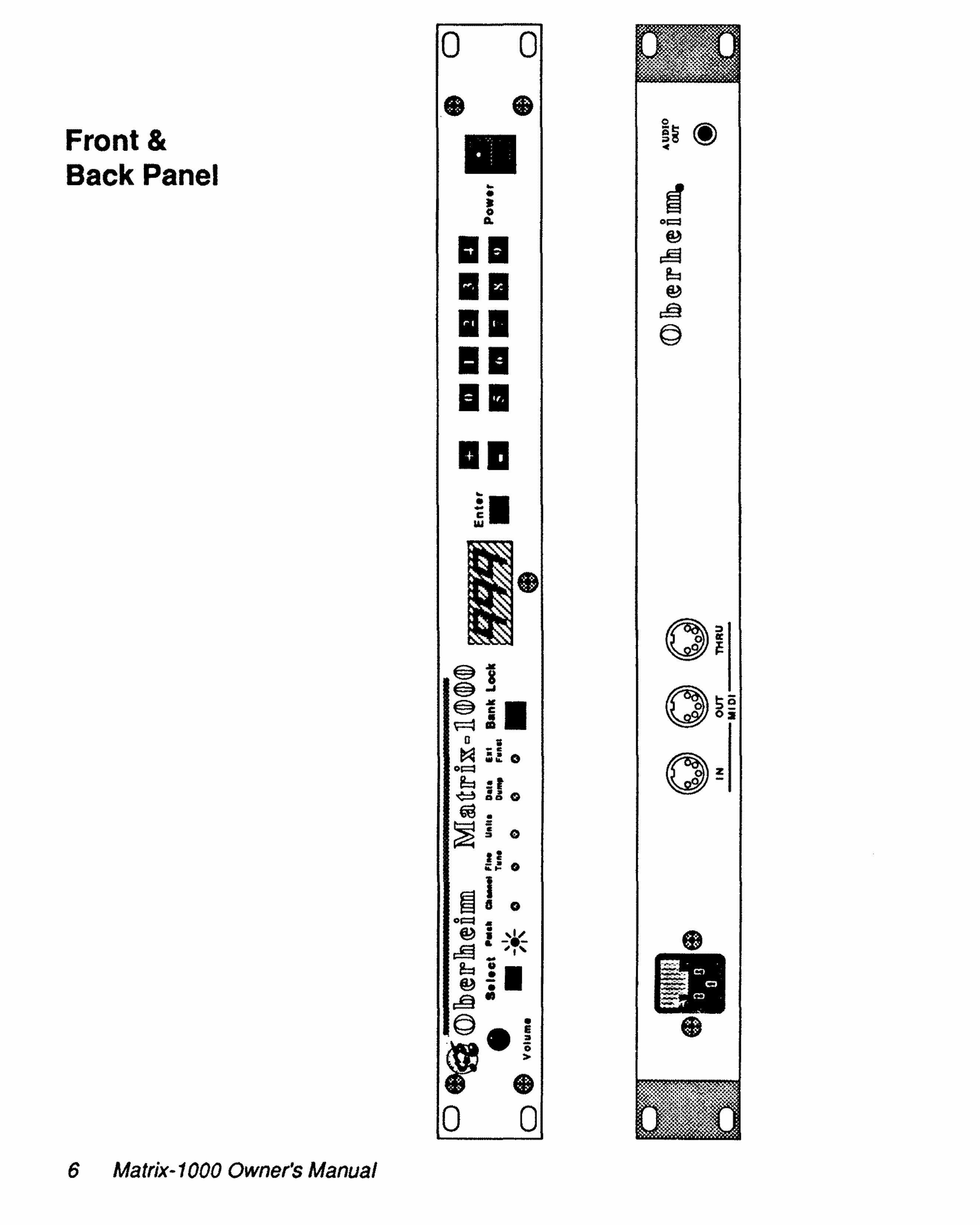
Front &Back Panel
6 Matrix-1000 Owner's Manual
o 0
.'•. :•
~.

IF YOU'RE IN A HURRY••••
Matrix-1000 Quick-Start Procedure
1. INITIAL SET UP -Place the Matrix-1000 on any level surface, or mount it in a rackcabinet.
• When rack-mounting the Matrix-1000, be sure to leave spaceabove and below the unit to insure proper ventilation.
2. HOOK IT UP -Connect the MIDI OUT of your Master instrument keyboard, MIDIguitar, wind controller, computer, etc.- to the MIDI IN of the Matrix1000. Refer to the Back Panel Layout diagram shown on Page 6 fordescriptions of the Matrix-1000's inputs and outputs.
3. TURN IT ON -Make ail your connections before powering the instrument on.
• When the Matrix-1000 is powered on, does the front paneldisplay Iight up? If not, check your connections.
4. SELECT MODE -Press the Select key repeatedly. The lights wïll"loop" around the sixheadings: Patch, Channel, Fine Tune, Units, Data Dump, and Ext.Funet.
a. Patch lets you select a patch. Use the Number Keys toenter a three-digit number from 000 through 999, or use the+ and - keys to advance or reverse the patch number. Or,select a patch from MIDI.
b. Channel lets you select the MIDI transmit and receivechannel. Use the + and - keys to select from MIDI Channels 1 through 16 or OMNI mode (displayed as on).
Matrix-1000 Owner's Manual 7

• Guitar Controller users (andsome others) maywish to select MONO mode (MIDI mode 4). Thisprovides independent pitch bend on each string.When the display reads G1, the Matrix-1000plays in MONO mode on basic channel 1.
c. Select Fine Tune, and use the + and - keys to finetune your Matrix-1000 to the other instruments inyour system. A display value of 0 is the center of therange (A=440 Hz).
The remaining modes are described in Chapter 4.
5. BANK LOCK -The Matrix-1000's patches are grouped in ten banks of 100patches each. The first digit of a patch number is the bank(0 through 9), and the last two digits are the location of thepatch within that bank (00 through 99).
Bank Lock lets you change patches within a bank by typingtwo digits instead of three. Select Patch mode, and pressBank Lock. A dot appears between the first and seconddisplay digits. Now, enter two digits to choose any patch inthe bank. Change banks by entering a digit from 0 through 9while holding down Bank Lock. Press Bank Lock again toreturn to three-digit patch selection. The display dot disappears.
6. ADJUST THE VOLUME -The Volume knob controls the volume level output of theMatrix-1000.
These brief procedures are explained in detai! throughout therest of the manual. We encourage you to read the manual in itsentirety if you would Iike to learn more about the Matrix-1000.
8 Matrix-1000 Owner's Manual

Chapter 1:
A FEW PRELIMINARIES
UnpackingACCESSORIESThe following items should be in the box when you open it:
• The Matrix-1000 Analog Sound Module• This Owner's Manual• Warranty Card• AC Cord• MIDI Cable• ECC/Oberheim Authorized Service Centers Directory
If any of these items is missing, contact the Oberheim Dealer whereyour Matrix·1000 was purchased.
RACK MOUNTINGThe Matrix-1 000 may be mounted in a standard 19-inch rack mountcabinet. To do this, you will need a Phillips-Head screwdriver and fourmounting bolts with washers.
The Matrix-1000 uses one standard rack space (1 -3/4 inches). Werecommend leaving an air space of approximately 1/2-inch between theMatrix-1000 and other units in the rack, to prevent overheating. This isespecially important if the Matrix-1000 will be left powered on for longperiods of time. We also recommend that the Matrix-1000 not bemounted adjacent to a power amplifier, or any other device that producesheat.
Matrix-1000 Owner's Manual 9

HookupAC POWERThe Matrix-1 000 runs on AC power between 95-130 volts or 200240 volts. It is set for the AC voltage of the country to which ithas been shipped from the factory. The voltage may, if necessary, be changed by a switch accessible through the bottom ofthe unit.
• The AC receptacle on the back panel is protected by apaper strip identifying the Matrix-1 OOO's factory ACvoltage setting. Check that your Matrix-1 000 is set forthe proper AC voltage. Then remove this strip, plug thefemale end of the AC cord into the Matrix-1000 and themale end into your wall outlet.
Warning: When the voltage is changed, the fuse mustalso be changed for continued protection against fire.See the information on the Matrix-1000 case or in theSpecifications section of this manual for further information on the correct fuse type and rating for each ACvoltage setting.
AUDIO and MIDI CONNECTIONSConnect the AUDIO OUTPUT jack of the Matrix-1 000 to a mixingboard, hi-fi system, instrument amplifier, or a sound system,using a standard audio cable (guitar cord) with a 1/4-inch plug .The Matrix-1 000 can be plugged into a Line Input, or an attenuated Microphone Input. Connect the Matrix-1000 to your soundsystem before powering on the Matrix-1 000.
10 Matrix-1000 Owner's Manual

Connect the MIDI OUT of your Master instrument - keyboard, MIDIguitar, wind controller, computer, etc. to the MIDI IN of the Matrix1000, using a standard MIDI interface cable. The MIDI Channel must bethe same for both your Master instrument and the Matrix-1 000, or elsethe Matrix-1000 must be in OMNI or MONO Mode. MIDI Channelselection is described under Channel mode in Chapter 2.
• Note that a MIDI cable is slightly different from the generic '5-pinDIN' cable available from some electronics retailers. Use of thisgeneric cable may result in 'ground-Ioop hum', which does notoccur with MIDI standard cables.
• Up to four MIDI instruments may be chained together by usingMIDI THRU, assuming that you are not using very long MIDIcables (maximum totallength for the entire rig is about 50 feet).
The order in which you power on your instruments is important. First, turnon the Matrix-1000, with its volume control set to its minimum (Volumeknob ail the way counter-cIockwise). Next, turn on your Master instrument. Then turn on the sound system - mixer first, then the poweramplifier. Powering on in this order will make sure that your Matrix-1 000sees ail the MIDI information sent by the Master, and prevent a possibleaudio "thump" from harming your speaker(s). When shutting down yoursystem, reverse the order: turn off the power amplifier, then the mixer,then the Matrix-1 000 and the rest of your instruments.
The Matrix-1 000 Back Panel Layout diagram on the Page 6 will assistyou in setting up the Matrix-1 000, showing the different connections thatare possible with the back panel jacks.
Matrix-1000 Owner's ManuaJ 11

CARE & MAINTENANCEFor proper care and handling, do not expose your Matrix-1 000 todirect sunlight or to temperatures above 1200 F (48.9 0 C).
Be careftl not to spill any liquids on or into the Matrix-1000. Donot expose the Matrix-1 000 to moisture or store it in an area thatis damp or has high levels of humidity.
To c1ean your Matrix-1000, use a soft cloth with mild soap (suchas dishwashing liquid) and luke-warm water. Spray-type windowcleaners are acceptable, but spray the c1oth, not the Matrix-1 000.Do not use harsh or abrasive detergents or solvents. We do notrecommend vinyl-treatment products, which leave a residue.
SERVICINGIf your Matrix-1 000 needs servicing, do not attempt repairsyourself. Refer to the section in the back of this manual titled IFY~U HAVE A PROBLEM, and contact your nearest ECC/Oberheim Authorized Service Center. A current list of ServiceCenters is included in the Owner's Packet along with this manual.
We encourage you to familiarize yourself with the WarrantyPolicy in the back of the manual. It outlines your rights andresponsibilities under the ECC/Oberheim Limited Warranty, andlists several important exclusions.
12 Matrix-1000 Owner's Manual

SpecificationsDescription
Polyphonic MIDI Synthesizer Module1000 Resident Patches6 Analog Voices
ModesPatch select
Polyphonic Playback of Pre-programmed Analog Sounds:200 RAM Patches; 800 ROM Patches
MIDI Channel 1 - 16 Select plus OMNI and MONO ModesFine TuneUnits select (multiple device cascade mode)Data DumpExtended Functions
Front PanelSelect Mode KeyBank Lock KeyEnter KeyNumeric Keypad with +and - keys3-eharacter Numeric DisplayVolume ControlPower Switch
Rear PanelMonophonic Audio Out JackMIDI IN, OUT and THRU PortsAC Receptacle
Power Requlrements (user selectable):North America and Japan: 95 -120v AC, 50 - 60 Hz, 55 watts max.Europe: 200 - 230v AC, 50 - 60 Hz, 55 watts max.
Fuse Requlrements100V 500mA Fast Acting120V 500mA Fast Acting220V 250mA Fast Acting240V 250mA Fast Acting
DimensionsWidth (side-to-side) 18.97 in. (48.18 cm.) Standard RackDepth (front-to-back) 10.94 in. (27.79 cm.)Height (top-to-bottom) 1.75 in. ( 4.45 cm.) 1 Rack Space
including feet 2.03 in. ( 5.16 cm.)Net Weight 9 tbs., 4 oz. (4.20 kg.)Shipping Weight 13 lbs. ( 5.90 kg.)
Specifications are subject to change wlthout notice.
Matrix-1000 Owner's Manual 13

14 Matrix-1000 Owner's Manual

Chapter 2:BASIC Matrix-1000 OPERATION
Front Panel KeysSELECT Key
The Select key accesses, one at a time, the six operating modes of theMatrix-1000: Patch, Channel, Fine Tune, Units, Dump and Ext. Funct.Press Select repeatedly. The indicator lights will "Ioop" around the sixmodes. The numeric display changes to correspond to the selectedmode.
"10
BANK LOCK Key
Select Pë
ln Patch mode, press the Bank Lock key to turn bank lock on and off.Hold down Bank Lock while pressing a Number key to change the bank.
ln any other mode, press Bank Lock to jump immediately back to Patch.mode.
The Bank Lock key also acts as a mute switch. Pressing Bank Lock atany time immediately silences the Matrix-1000.
Matrix-1000 owners Manual 15

ENTER, + and - Keys and Number Keys
EnterEnter is used as a store key for the Patch Copy feature andfor storing programmable group mode. It may be used asan on/off switch for sorne functions, such as MIDI echo.Finally, the Enter key is used to start data dumps andcalibration routines.
•
Enter
+and-KeysThe + and - keys change values up and down by 1. Forinstance, in Patch mode, + selects the next patch, andselects the previous patch. When held down, + and repeat automatically. + and - may also act as on and offswitches in Ext. Funct. mode.
Number KeysThe Number keys are used to type values directly. Forinstance, in Patch mode, the Number keys are to enterpatch and bank numbers. With the exception of Ext. Funct.mode, values may be changed using either + and - or theNumber keys. In Ext. Funct., the Number keys select thedifferent Extended functions, and only the + and - keys maybe used to change values.
16 Matrix-1000 Owner's Manua/

Basic ModesPATCH
This is the mode you will use most often. In this mode, the displayshows which of the 1000 sounds you are playing. Patches are numbered000 through 999. You can change patches either from the Matrix-1000front panel or from MIDI.
c:
Select Patch Channel Fine Units Data Ex'
,1/Tune Dump FUI
-G- O 0 0 e 0.:. .:. .:. :. •••
/1"
Patches are grouped in ten banks of 100 patches each. The first digit ofa patch number is the bank (0 through 9), and the last two digits are thelocation of the patch within the bank (00 through 99). For instance, patch427 is bank 4, location 27.
Selecting a Patch From the Front Panel
• Press the Bank Lock key ta turn bank lock on and off. Thedecimal point between the first and second display digits turnson and off. Turning on bank lock freezes the bank number.
• When bank lock is off, use the Numbor keys ta type in thethree-digit number (000 through 999) of the desired patch. Or,press + or - until the desired patch is displayed.
Matrix-1000 Owner's Manual 17
1 ~
• When bank lock is on, type the two-digit number (00through 99) of the desired patch in the current Bank.Or, press + or - until the desired patch in the currentBank is displayed. To change Banks, hold down BankLock and type the digit of the desired Bank (0 through9).
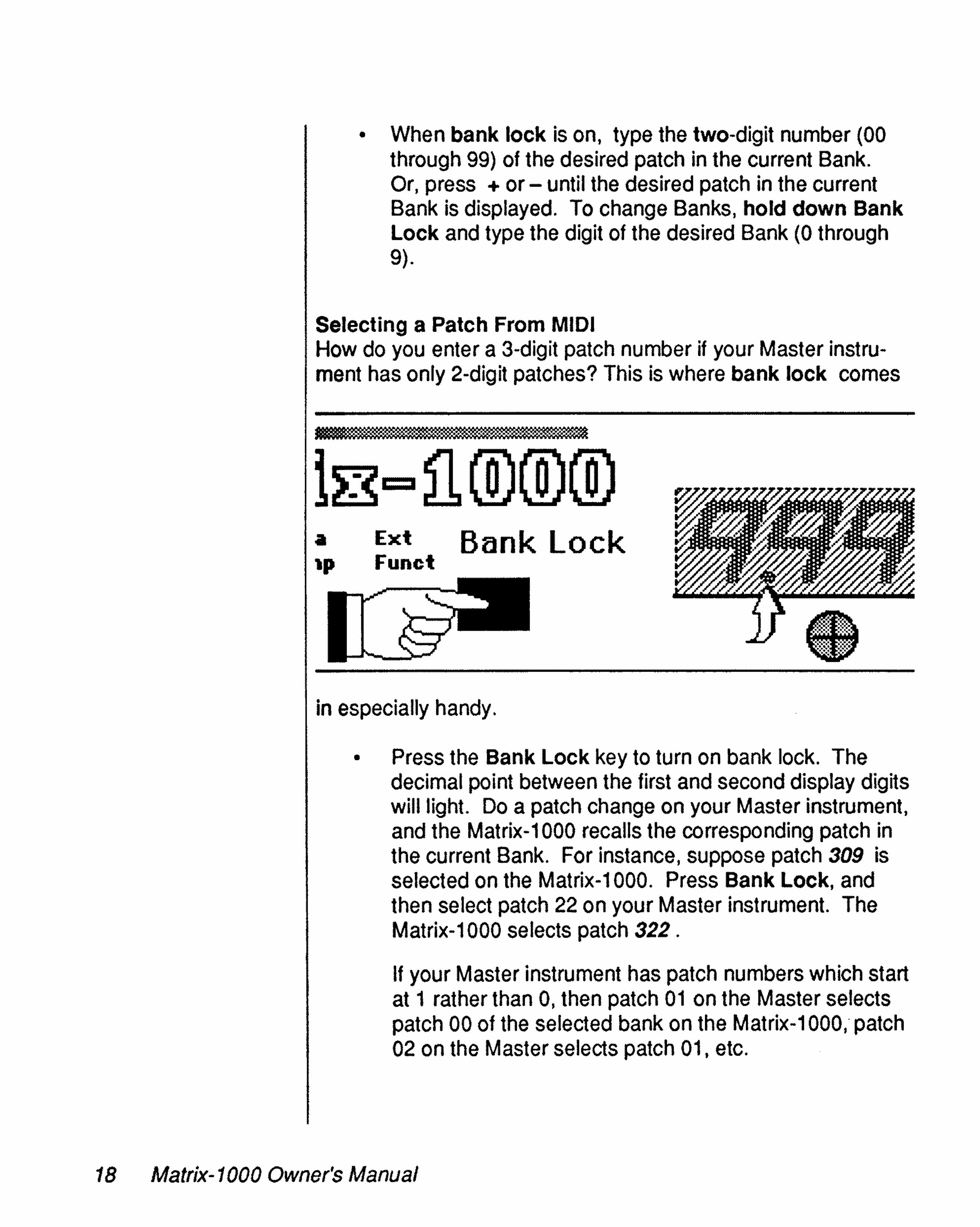
Selecting a Patch From MIDIHow do you enter a 3-digit patch number if your Master instrument has only 2-digit patches? This is where bank lock cornes
a Ext Bank lock'P Funct
in especially handy.
• Press the Bank Lock key to turn on bank lock. Thedecimal point between the first and second display digitswilliight. Do a patch change on your Master instrument,and the Matrix-1000 recalls the corresponding patch inthe current Bank. For instance, suppose patch 309 isselected on the Matrix-1000. Press Bank Lock, andthen select patch 22 on your Master instrument. TheMatrix-1000 selects patch 322.
If your Master instrument has patch numbers which startat 1 rather than 0, then patch 01 on the Master selectspatch 00 of the selected bank on the Matrix-1000, patch02 on the Master selects patch 01, etc.
18 Matrix-1000 Owner's Manual

• To change banks from MIDI, push (or pull) the Mastercontroller's Vibrato or Modulation wheel, lever or joystick (MIDIcontroller #1) to its maximum position. While holding theMaster's Vibrato control at its maximum, select a patch from 0through 9 on the Master. The bank of the same number isrecalled on the Matrix-1000. For instance, suppose patch 322 isselected on the Matrix-1000. Hold the Vibrato control and selectpatch 4 on the Master. The Matrix-1000 selects bank 4, so thepatch changes from 322 to 422.
If your Master has patch numbers which start at 1 rather than 0,then patch 1 selects bank 0, patch 2 selects bank 1, etc.
• ln short, wheneverthe Matrix-1000 sees a MIDI Patch Changewhen the Vibrato or Modulation (MIDI controller #1) is more thanhaIf way on, it uses the patch number as a bank number. So becareful if you're playing notes with your Vibrato on, and youmake a Patch change, the Matrix-1000 understands that as abank change commando To allow bank changing without usingVibrato, MIDI controller #31 performs the same funetion. Thismode is the same as that found in the Oberheim DPX-1 andsome other instruments.
• If bank lock is turned off, the Matrix-1000 will receive patches000 through 127 over MIDI. If a bank change is sent from MIDI,using either the Vibrato or MIDI controller #31, the Matrix-1000turns on bank lock automatically.
MIDI patch changes are transmitted and received by the Matrix-1000on its Basic Channel. Patch changes and bank changes are received by the Matrix-1000 in ail front panel modes, not just Patch.
Matrix-1000 Owner's Manual 19

CHANNEL
This mode contrais the MIDI channels used by the Matrix-1000ta send and receive MIDI messages such as notes, patchchanges and pitch bends. It's important ta make sure the Matrix1000 is Iistening ta the channel or channels being sent by yourMaster instrument. When Channel mode is selected, you canset the Matrix-1000 into any of these receive modes, using the +and - and Number keys:
•
Select Patch Channel Fine Units Data
,1/Tune Dump
e -G- O 0 e.:. .:. .:. :-
/1'
• A number from 1 ta 16 indicates the channel on whichmessages are transmitted and received.
• on indicates that OMNI mode is active. In this mode,the Matrix-1000 receives messages on ail channels,and transmits on channel 1.
• Displays from G1 ta G9 mean that the Matrix-1000 is inMONO mode (MIDI mode 4), with basic channels 1through 9. The G here stands for guitar, since MONOmode is usually used with guitar controllers ta allowindependent pitch bend on each string.
20 Matrix-1000 Owner's Manual

When G1 is selected, the Matrix-1000 is in MONO mode with MIDIChannel 1 as the Basic Channel. MIDI Patch Change commands arerecognized on Channel 1, and the Voices respond to Notes and Controllers (Pitch Bend, Volume Pedal and Pressure/After-Touch) independentlyon the first six MIDI Channels: Voice 1 on Channel 1, Voice 2 on Channel 2, Voice 3 on Channel 3, etc. When G2 is selected, the same thinghappens, except that MIDI Channel 2 ls now the Basic Channel, andVoice 1 plays on Channel 2, Voice 2 on Channel 3, Voice 3 on Channel4, etc. See the chart below for the exact channels that are used inMONO mode. Vibrato and Sustain Pedal are received on the lowestchannel number and used for ail volces when in MONO mode.
When proper MIDI communication is occurring, the Matrix-1000 Iights adot in the lower right-hand corner of the display any time a note isplaying. If the dot does not appear while you are playing, check bothyour MIDI Channel selections and your MIDI cable connections.
The MIDI channel and MIDI Mode (OMNI/POLY/MONO) are stored inmemory, so that you do not have to set up the mode and channel whenyou turn on the power. While the MIDI channel can be changed onlyfrom the front panel, the MIDI mode can be changed remotely from MIDI.If the Channel display seems to change mysteriously, make sure thatyour Master instrument is not sending Mode Change Messages.
Refer to the following chart to determine the Voice-to-Channel assignments of the nine MIDI MONO modes of the Matrix-1 000. Notice that G9js the top MIDI Channel represented. The Matrix-1000 does not operatein MIDI MONO for Channels 10 through 16.
Display Basic Voice 1 Voice 2 Voice 3 Voice 4 Voice 5 Voice 6Channel Channel Channel Channel Channel Channel Channel
G1 1 1 . 2 3 4 5 6G2 2 2 3 4 5 6 7G3 3 3 4 5 6 7 aG4 4 4 5 6 7 a 9G5 5 5 6 7 a 9 10G6 6 6 7 a 9 10 11G7 7 7 a 9 10 11 12Ga a 8 9 10 11 12 13G9 9 9 10 11 12 13 14
Matrix-1000 Owner's Manual 21

FINE TUNE
The Matrix-1000 is normally tuned ta Standard Pitch of A = 440Hz, but it can be adjusted to match the tuning of other instruments in your system.
Select P.atch Ch.annel Fine Units D.at.aTune Dump
,1/0 0 -G- @ e.:. .:. •• :.
/1'\
When Fine Tune is selected, the Display reads the current FineTune value. This value is stored in memory until it is changed.Change the value by using the + and - keys or the Numberkeys.
The range of Fine Tune is ± a 1/4-tone, represented on thedisplay as a number from +31 to -31. When the display readsD, A = 440 Hz. Positive numbers indicate sharp tunings, andnegative numbers indicate fiat tunings.
22 Matrix-1000 Owner's Manual

TRANSPOSE, UNISON, MIDI ECHO
The Ext. Funct. mode of the Matrix-1 000 contains Extended Functions.There are presently eight of thèse functions, numbered 0 through 7 andthey are not saved with each patch, although they are saved when youturn the power off. Numbers 0 through 2 are the ones you will need mostoften.
1 1
elect Patch Channel Fine Units Data ExtTune Dump ~unct
" /e 0 0 0 {il) -G-• • .:. .:. .:. :.•
/1"
ln Ext. Funct. mode, the Number keys select the function, while the +and - keys change the on or off status or number value. What's important to remember ls that the function number is not displayed. Instead,each Extended Function has its own unique display:
Common Extended Functions
Press Number Key: Display Reads:
o Uonor
Uof
1 tm
2 Eonor
Eof
Definition:
Unison mode is ON.
Unison mode is OFF.
Transpose mode.
MIDI Echo is ON.
MIDI Echo is OFF.
Matrix-1000 Owner's Manual 23
o Unison
Unison mode causes the Matrix-1000 to play ail six Voices withone key depression. This is effective for fattening up certainsounds Iike basses and leads.
Sorne patches are pre-programmed to be in Unison. Most arenot. The front-panel Unison overrides the pre-programmedUnison.
• Use the + key to turn Unison on and the - key to turn it off,or press Enter to switch between on and off.
• ln Unison, if more than one note is played, only the lowestnote held will be heard.
Unison is not the same as the "Mono keyboard mode" found onsorne instruments. Mono keyboard mode allows you to play onlyone Voice monophonically. Unison plays ail six Voices togetheras a single note. This is why the Matrix-1000 sounds richer andlouder in Unison mode.
When you play legato, the sound may or may not retrigger. Thisis programmed as appropriate for each patch.
1 TransposeYou can transpose the pitch of the Matrix-1000 up ordown asmuch as two octaves.
• Press Select until you reach Ext. Funct. Press 1 to choosethe Transpose function. The display reads lm.
• Press Enter to display the transpose amount.
• Use the + and - keys to change the transposition amount.You can play as you change the value, to hear how thetranspose sounds.
24 Matrix-1000 Owner's Manual

The transposition is displayed in semitones. 0 indicates standard pitch.To transpose up an octave, set the transpose value to 12. To transposeup two octaves, set the value ta 24, etc.
2 MIDI EchoWhen MIDI echo is on, ail MIDI IN data received by the Matrix-1000 issent back out the MIDI OUT port. In other words, MIDI echo makes theMIDI OUT port act like a MIDI THRU port, but with the advantage thatyou can switch it on and off without unplugging any cables.
• Use the + key ta turn MIDI echo on and the - key to turn it off, orpress Enter ta switch between on and off.
Use MIDI echo ta layer sounds from several Matrix-1000s, orfrom aMatrix-1000 and another synthesizer. For example, to layer threeMatrix-1000s:
• Connect the MIDI OUT (not THRU) of the first Matrix-1000 to theMIDI IN of the second. Connect the MIDI OUT of the second ta theMIDI IN of the third.
• Set your Master instrument and ail the Matrix-1000s to MIDI channel1, as described under Channel.
On the first Matrix-1000, press Select until you reach Ext. Funct.Press 2 to choose the MIDI echo function. Press + to turn MIDIecho on. Now do the same on the second Matrix-1000. Since thethird Matrix-1000 is the last in line, you do not need to turn on itsMIDI echo.
• That's it! Now when you play a note on your Master instrument,you'lI hear ail three Matrix-1 OOOs play.
Layer several different Matrix-1000 patches for orchestral effects. Or, seteach Matrix-1 000 ta a different Fine Tune value, and layer the samepatch to get super-fat pads and unisons.
Matrix-1000 Owner's Manual 25

MIDI echo ls also used in conjunction with group mode, as described in Chapter 4.
With the exception of MIDI Active Sensing, ail MIDI data isechoed, even System Exclusive messages. However, use ofMIDI echo for MIDI Real lime information, such as drum machine clocks, is not recommended.
Hints for playing the Patches
• Use the controllers. The Matrix-1 000 can use Pitch Bend,Pressure, Mod Wheel (Controller #1), Breath Control (#2),Pedal Control (#4), and Sustain (#64). Although they maynot ail be used in every patch, you may find some interestingeffects.
• Hold notes for a long time, and let them release for a longtime. Lots of things are controlled by envelopes. Playingstaccato is good for other patches.
• Play cJusters of notes. This is good for many sound effects.
• Play the sound at different places on the keyboard.
The bottom line is Experiment. The Matrix-1 000 ls one of theworld's most dynamic synthesizers and can do some veryunusual things. Programmers have taken advantage of this, soail the patches may not be what }'OU expect. If a sound isuninteresting, you are probably playing it wrong!
26 Matrix-1000 Owner's Manual

Chapter3:ABOUT THOSE 1000 PA TCHES...
At the heart of the Matrix-1000 is the same circuitry used to produce thesounds in the Oberheim Matrix-6 keyboard and the Matrix-6R rack mountsynthesizer. Recent advances in technology have permitted the samerich sounds to be packaged in a t-rack space unit at a considerablylower cost.
The Matrix-1000 contains sounds that have been compiled over that lastseveral years from Matrix-6 and Matrix-6R owners from ail over theworld. Just recently, Oberheim released a cassette data tape with thesesounds to Matrix-6/6R owners so that they will be able to enjoy thetremendous f1exibility of having one thousand synthesizer sounds on onecassette.
The Matrix-6 and Matrix-6R, however, can store only 100 of the Patchesfrom the tape at a time. With the Matrix-1000, you have immediateaccess to ail 1000 Patch sounds because they are ail stored inside theMatrix-1000.
But it doesn't stop there. In Chapter 4, under the Data Dump mode, we'lItell you how you can customize your patches via MIDI. Right now, we'lIcover another way to customize the Matrix-1000.
Copying Patches Within the Matrix-1000
After playing the Matrix-1000 for a period of time, you may want to movecertain sounds to new memory locations. The Patch Copy function letsdo just that. You can copy FROM any patch from 000 through 999 TOany patch from 000 through 199. You cannot copy TO patches 200through 999 ; they are permanent.
The patch you copy FROM is called the source patch. The patch youcopy TO is the destination patch. When you copy a patch, the oldcontents of the destination patch is ERASED and replaced with thesource patch. Be sure to copy only TO a patch which you don't need tosave.
Matrix-1000 Owner's Manual 27

o Press Select until you reach Patch mode. Select thepatch that you want to copy FROM.
o Press and hold down the Enter key. The Displaychanges to read sto for "store".
o While still holding Enter. type the three-digit number ofthe patch you want to copy TO.
o When the third digit is pressed, the new patch number isdisplayed, and the copy is complete. The old patch atthat number is ERASED and replaced with the copiedpatch.
o If you make a mistake before the third digit is pressed,let go of Enter and start over.
If the display shows Pro instead of sto when you press Enter,the memory has been protected. Memory Protect must beturned off betore any patches can be copied or stored. SeeChapter 4 under Ext. Funct. #6.
28 Matrix-1000 Owner's Manual
Chapter4:ADVANCED Matr/x-1000 OPERATION
SPECIAL MODESUNITS
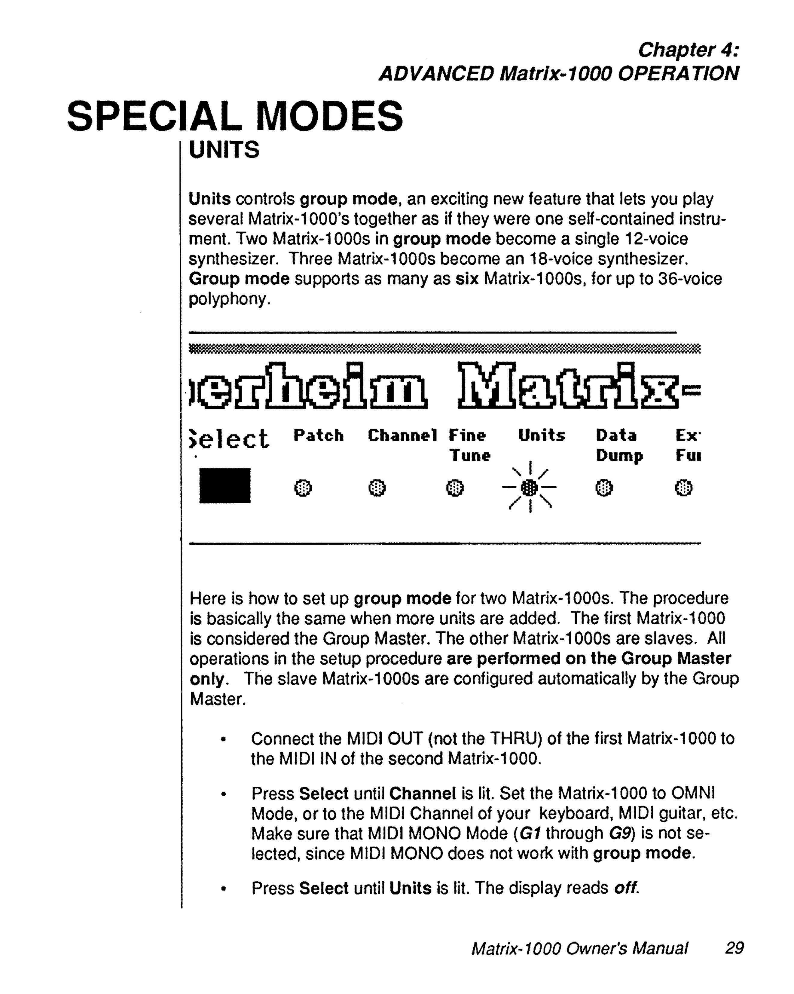
Units controls group mode, an exciting new feature that lets vou playseveral Matrix-1 OOO's together as if they were one self-contained instrument. Two Matrix-1 OOOs in group mode become a single 12-voicesynthesizer. Three Matrix-1 OOOs become an 18-voice synthesizer.Group mode supports as many as six Matrix-1000s, for up to 36-voicepolyphony.
•
>elect Patch Channel Fine Units Data Ex'• Tune Dump FUI
,1/0 (TI) (TI) -G- O 0.:. .:. .:. :. • ••
/1"-
Here is how to set up group mode for two Matrix-1000s. The procedureis basically the same when more units are added. The first Matrix-1000is considered the Group Master. The other Matrix-1 OOOs are slaves. Alioperations in the setup procedure are performed on the Group Masteronly. The slave Matrix-1000s are configured automatically by the GroupMaster.
• Connect the MIDI OUT (not the THRU) of the first Matrix-1000 tothe MIDI IN of the second Matrix-1000.
• Press Select until Channel is lit. Set the Matrix-1000 to OMNIMode, or to the MIDI Channel of your keyboard, MIDI guitar, etc.Make sure that MIDI MONO Mode (G1 through G9) ls not selected, since MIDI MONO does not work with group mode.
• Press Select until Units is lit. The display reads off.
Matrix-1000 Owner's Manual 29

• Use the + key to select the total number of Matrix-1 OOOsthat you want to group together. Since there are twounits in this case, the number 2 should be displayed.Also, the dot between the second and third displaydigits lights up. This dot remains lit whenever your are ingroup mode.
• Now for the fun part...playing! When you play in groupmode, the first note plays on the first Matrix-1000, thesecond note plays on the second Matrix-1000, the thirdnote plays back on the first, the fourth note goes to thesecond, etc. We cali this note assignment "AlternatingRotate". Achieve stereo effects by panning the output ofeach Matrix-1 000 to a different stereo position on yourmixer, and multitimbral effects by setting each Matrix1000 in a Group to a different patch.
• Select Patch mode, and choose a new patch. Patchand bank changes on the Group Master are transferredautomatically to the rest of the Group. (Other changes,Iike Fine Tune, must be made on each unit individually.)
• To leave group mode, return to Units, and reset thenumber of units to off.
Group mode works together with MIDI echo to make it easy toswitch between layered and many-voiced polyphonic textures.Set up group mode as above, and then do the following:
• Press Select until Units is displayed. Notice that the dotbetween the second and third display digits is lit, toindicate group mode.
• Press Enter. The dot disappears. The current patch willnow ignore group mode. Press Enter again to turngroup mode back on for this patch. The dot reappears.
• Turn on MIDI echo on both Matrix-1000s, as describedin Chapter 2. This must be done on each unit separately.
30 Matrix-1000 Owner's Manual

• Return to Units mode. Now both group mode and MIDI echoare on.
• Play sorne music! Notice that group mode takes precedenceover MIDI echo. With group mode on (display dot lit), the twoMatrix-1 OOOs play together as a 12-voice instrument. With groupmode off (no dot), they become a layered six-voice instrument.Press Enter in Units mode to switch back and forth.
For even greater flexibility, you can program each patch on the GroupMaster to use or ignore group mode. The Matrix-1 000 is shipped fromthe factory with ail patches programmed to use group mode. If you wantto use a particular patch as a layer, program it to ignore group mode.Doing this is very similar to Patch copy. In tact, it's Iike copying a patchto itself.
• Press Select until Units is displayed. Use Enter to turn groupmode off for the patch.
• Press Select until Patch is displayed. Press and hold Enter.The display reads sto, for "store". As with Patch Copy, MemoryProteet must be off when storing the group mode setting for apatch.
• Type the three-digit patch number of the current patch. Thepatch will now ignore group mode. Ali patches, even the ROMpatches 200 through 999, may be programmed to ignore groupmode.
• To turn group mode back on for a patch, go to Units, use Enterto turn group mode back on, and copy the patch to itself again.
Matrix-1000 Owner's Manual 31

Vou can use group mode to combine a Matrix-1000 with aMatrix-6 or Matrix-6R to make a 12-voice instrument:
• Vou must have Matrix-6/6R software revision 2.13 orlater.
• Connect Matrix-6 MIDI OUT to Matrix-1000 MIDI IN, andMatrix-1000 MIDI Out to Matrix-6 MIDI IN. OR, ConnectMaster to Matrix-1000 MIDI IN, and Matrix-1000 MIDIOUT to Matrix-6R MIDI IN.
• Set Matrix-6/6R Master Parameter 00 BASIC CHAN 01.• Set Matrix-6/6R Master Parameter 01 OMNI ON.• Set Matrix-6/6R Master Parameter 05 LOCAL CTL OFF.
.• Set Matrix-6/6R Master Parameter 13 SPILLOVER OFF.• Set Matrix-1000 Channel to on.• Set Matrix-1 000 Units to 2 to turn on group mode.
ln fact, group mode can actually be used between aMatrix-1000 and any other single synthesizer. The Matrix-1 000must be the Group Master, and the other synthesizer will beassumed to have only six voices. The other machine must beset to Basic Channel 1.
DATA DUMP
Data Dump is used to send patches between the Matrix-1000and another device: a second Matrix-1000, a Matrix-6 Keyboard, the Matrix-6R rack mount or a computer equipped with aMIDI interface and Matrix-6/6R patch Iibrarian or editor program.Vou can use Data Dump to back up your patches, load in newpatches, or even to edit sounds trom a computer.
32 Matrix-1000 Owner's Manual

You should know that the Matrix-1000 uses two different kinds of memory for patches. The first 200 Matrix-1000 sounds (Patch numbers 000through 199) stored in RAM (Random Access Memory). This meansyou can edit, change, overwrite or otherwise customize them. Theremaining 800 sounds (Patch numbers 200 through 999) are in permanent ROM (Read Only Memory) and cannot be changed. Patch backupsare unnecessary for ROM sounds, but are highly recommended for theRAM sounds.
1 ~
>elect Patch Channel Fine Units Data ExtTune Dlump Func
0'\. /
Cl 0 -G- O.:. .:. ID:. .:/1'\
Saving Patches: Dumping FROM the Matrix-1000
• Connect the MIDI OUT of the Matrix-1 000 to the MIDI IN of thereceiving device.
• Make sure that MIDI System Exclusive is enabled on the receiving device.
• Press Select on the Matrix-1000's front panel until Data Dump islit.
Matrix-1000 Owner's Manual 33

• Use the + and - keys or the Number keys to choosefrom the three Data Dump options:
Press Display Reads:Number Key:
o Odb
1 1do
2 2dA
Definition:
Dump bank: Send the 100patches in the currently selectedbank.
Dump one: Send the currentpatch.
Dump ail: Send the entirecontents of RAM, patches 000through 199.
• Press Enter. The selected data is sent to the receiver.
If Dump ail is used to send the RAM patches to another Matrix1000, the receiving unit will be left with bank lock enabled andand bank 1 selected.
Loading Patches: Dumping TO the Matrix-1000
• Connect the MIDI OUT from the transmitting device tothe MIDI IN of the Matrix-1000.
• Make sure that MIDI System Exclusive is enabled on thetransmitting device.
• Make sure that Memory Protect (Ext. Funct. #6) isturned off on the Matrix-1000. If Memory Protect is onwhen the Matrix-1000 receives a patch dump, it willignore the dump.
• Execute the desired function trom the transmittingdevice, and the Matrix-1000 automatically saves the newpatches. The Matrix-1000 does not need to be in anyspecial mode to receive a patch dump.
34 Matrix-1000 Owner's Manual

• When the dump is completed, select Patch mode on the Matrix-1000. The received patches are now available.
Note that Matrix-6 and 6R units with software version 2.13 or earlier maytransmit patches faster than the Matrix-1000 can receive them during aSEND ALL. The result may be that some patches are not successfullytransferred. These patches can be sent using the Matrix-6 SEND ONEfunction. Aiso note that the Matrix-6 will send Split and Master information during a SEND ALL. This extra information will be ignored.
Matrix-1000 Owner's Manual 35

ADVANCED EXTENDED FUNCTIONS
Here are the remaining Extended Functions not described inChapter 2.
•1 ~
t Patch Channel Fine Units Data ExtTune Dump ~unct
" /e 0 0 0 0 -G-o' -:. .:. .~. :.•
/1"
Advaneed Extended Funetions
Press Display Reads:Number Key:
3 ionoriof
4 PEd
5 GOO
6 PonorPot
7 tst
8 bnd
36 Matrix-1000 Owner's Manual
Definition:
InvertMIDI Volume is ON.•
Invert MIDI Volume is OFF.
Pedal1 MIDI eontrollerselect.
Displays the Unit Numberused in group mode.
Memory Protect is ON.
Memory Proteet is OFF.
Test mode.
Bend Range.

3 Invert MIDI VolumeThe Matrix-1000 normally gets louder as MIDI Volume (Controller #7) isincreased. When Invert MIDI Volume is on, the Matrix-1000 gets sotteras MIDI Volume is increased. This may seem rather strange, but itallows two rather nice effects:
• Whammy bar. Certain controllers, notably the whammy bar on aMIDI guitar, transmit a 0 in the rest position. If you use the whammybar to control MIDI Volume, you must hold the whammy bar down toget any sound at ail. By inverting Volume, you get maximum volumewhen you're not using the whammy bar, and softer volume as youpress the bar down.
• Cross-fade. When used with a synthesizer which responds normallyto MIDI Volume, inverting the volume on the Matrix-1000 creates across-fade. As the volume increases on the other synthesizer, itdecreases on the Matrix-1000, and vice-versa.
Use the + key to turn MIDI Volume Invert on and the - key to turn it off,or press Enter to switch between on and off.
4 Pedal 1 MIDI Controller SelectThe Pedal1 select function is used primarily to provide compatibility withMatrix-6 and 6R synthesizers. Pedal1 can be programmed to allow awide variety of.effects on the Matrix series synthesizers. As a result,many of the sounds in the Matrix-1000 have special effects programmedon the Pedal 1 function. On the Matrix-6, Pedal1 is assignable to anyMIDlcontroller, but defaults to MIDI controller #7. On the Matrix-1000,Controller #7 is dedicated to the volume function. To provide compatibility with systems where a Matrix-6 is presently being used, the Matrix-
'1000 allows the Pedal1 function to be controlled by any standard MIDIcontroller. The Pedal1 function defaults to MIDI controller #4, but can bereset to any controller in the range 0-121. A special case is when thePedal1 is assigned to controller #7. In this case, the MIDI Volumefunction ls defeated, and the controller will be routed exclusively to thePedal1 function.
Matrix-1000 Owner's Manual 37

Select Ext. Funct. #4. The display reads PEd. Press Enter todisplay the current Pedal1 MIDI controller. Use the + and keys to change the controller number from 0 through 121.
5 Display Group Mode Unit Numberln group mode, the Group Master ls considered unit 0, the firstslave Matrix-1000 in the Group is unit 1, the next is unit 2, etc.The Group Master transmits notes to each slave on the MIDIchannel number corresponding to the slave's unit number.. Forinstance, notes for slave unit 1 are transmitted on channel 1. Atthe same time, the slave unit receives notes on this new channel, instead of its originally selected channel.
Display Group Mode Unit Number lets Vou view and modifythe unit numberof a particular Matrix-1000. Entering groupmode on the Group Master resets this value on ail slavesautomatically. By changing this value after group mode hasbeen turned on, Vou can achieve certain special effects. Anyinstrument with a unit number of 0 will act Iike a master, whileany non-zero unit number will act Iike a slave. Given this, it isactually possible to use Matrix-1000's in combination with anyother synths, although each synth will play only six volces.
6 Memory ProtectWhen on, this funetion protects the first 200 patehes from beingoverwritten. Use the + key to turn Memory Proteet on and the key to turn it off, or press Enter to switch between on and off.
When Memory Protect is on, pressing the Enter key while inPatch mode causes the display to read Pro instead of the usualsto . Memory Protect prevents Pateh Copy and Data Dumpreeeives (though not transmits). Vou cannot program a patch touse or ignore group mode while Memory Proteet is on.
38 Matrix-1000 Owner's Manual

7 Test ModeThe Matrix-1000 software includes a number of test routines used duringmanufacture and servicing. To access these functions, select Ext. Funct.#7 and press Enter. The display will then show the test number. The +and - keys change the test number.
Test 0 is an auto-calibrate funcnon, a comprehensive internai routine thatauto-tunes the instrument's Oscillators. Filters. Voltage ControlledAmplifiers (VCAs) and other related circuits. Press Enter to start calibration. The display reads CAL. Calibration takes several seconds to complete.
The remaining test functions are useful only to service centers:
NOTE: The Matrix-1000 must only be opened and adjusted byqualified service personnel. Unauthorized adjustments may voidyour warranty.
1 Voice display. Press Enter to toggle display mode. When active.display shows highest gated volee number, or 0 if no voices aregated. This test remains active during ail modes until calibrationtest 1 is re-selected and Enter is pressed, or until power iscycled.
2 DAC Zero. Press Enter to start. Adjust VR701 for OV±1 mV atDACOUT test point. Press any key to end test.
a Bend Ran-geVou can set the range used by the pitch bend control to be as much astwo octaves.
• Press Select until you reach Ext. Funct. Press 8 to choose theBend Range function. The display reads bnd
• Press Enter to display the bend range amount.
• Use the + and - keys to change the bend range amount. Vou canplay as you change the value. to hear how the bend sounds.
The bend range is displayed in semitones. The normal value is 2 whichmeans that the full bend range is up 2 semitones and down 2 semitones.For a one octave up and one octace down range, set the value to 12.
Matrix-1000 Owner's Manual 39
RE-INITIALIZATION
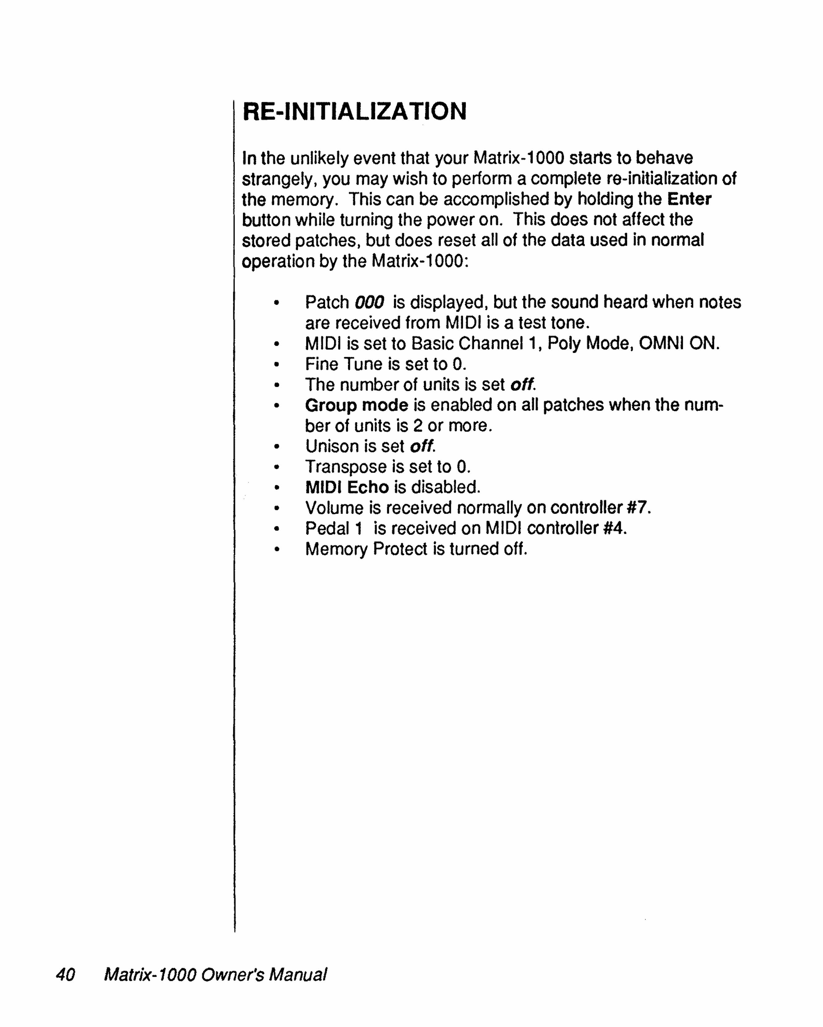
ln the unlikely event that your Matrix-1 000 starts to behavestrangely. you may wish to perform a complete re-initialization ofthe memory. This can be accomplished by holding the Enterbutton while turning the power on. This does not affect thestored patches, but does reset ail of the data used in normaloperation by the Matrix-1000:
• Patch 000 is displayed, but the sound heard when notesare received from MIDI is a test tone.
• MIDI is set to Basic Channel 1, Poly Mode, OMNI ON.• Fine Tune is set to O.• The number of units is set off.• Group mode is enabled on ail patches when the num-
ber of units is 2 or more.• Unison is set off.• Transpose is set to O.• MIDI Echo is disabled.• Volume is received normally on controller #7.• Pedal1 is received on MIDI controller #4.• Memory Protect is turned off.
40 Matrix-1000 Owner's Manual

Recognized MessagesChannel Voice Messages
Chapter5:MIDI SUMMARY
1000 xxxx
1001 xxxx
1011 xxxx
1100 xxxx
1110 xxxx
.Data Bytes
Onnn nnnnOvwwvv
Onnn nnnnOvwwvv
Occe ceccOnnn nnnn
Onnn nnnn
OOOOOOOnOnnn nnnn
Qescriptiol1
Note Off(Release Velocity = 1 - 127)
Note On(Velocity = 1 - 127, 0 = Note Off)
Controller ChangeAny controller 0 - 121 can be used;7 bits only
Program Select
Pitch Bend (LSB)Pitch Bend (MSB)
Channel Mode Messages
1011 xxxx
1011 xxxx
1011 xxxx
1011 xxxx
1011 xxxx
1011 xxxx
79HOOH
7BHOOH
7CHOOH
7DHOOH
7EH06H
7FHOOH
Reset Ali Controllers
Ali Notes Off
OMNI Mode Off
OMNI Mode On(OMNI is assumed off inMONO ON)
Mono ModeOn
Mono Mode Off
Matrix-1000 Owner's Manual 41

System Common Messages
1111 0000 10H System Exclusive - Oberheim ID06H Matrix-6/6R11000 Device ID<opcode><data bytes>OF7H End of System Exclusive
1111 0111 End of System Exclusive
System Real Time Messages
1111 1110 Active Sensing
Matrix-1000 System Exclusive Data FormatAli "data" in patch and parameter dumps is unpacked for transmission.The general algorithm for transmission is:1. Transmit header and message code(s).2. Clear checksum.3. Fetch next data byte to be transmitted.4. Add byte to checksum.5. Transmit (data & OFH).6. Transmit (data/16 & OFH).7. Repeat 3 - 6 for ail data bytes.8. Transmit (checksum & 07FH).9. Transmit F7H.
01 H - Single Patch DataFOH 10H 06H 01 H -enums <patch data> echecksums F7H
<oum> .. destination patch number (0 - 99)< data> .. patch data unpacked to two nibbles per byte
see patch format listing-echecksum» .. sum of packed (.QQ1 transmitted) <data>
Note: On receipt, this data will be stored into the specifiedpatch location in the current bank. If this patch is currentlyselected in the Matrix-1 000, the newly stored sound will berecalled into the edit bufter.
Note: A gap of at least ten msec should be allowed betweenpatches when sending multiple patches to the Matrix-1000.
42 Matrix-1000 Owner's Manual

03H - Master Parameter DataFOH 10H 06H 03H <version> <data> -echecksums F7H
•<version> = 03H for Matrix-1000
<data> = master data unpacked to two nibbles per bytesee master parameter format listing
-echecksum» = checksum of packed <data>
04H - Request DataFOH 10H 06H 04H <type> -enumber» F7H
<type> = 0 to request ail patches in current bank and masterparameters.= 1 to request a single patch from the current bank.= 3 to request master parameters.= 4 ta request edit buffer.
-enumbeo« 0 when <type> = 0 or 3= Number of patch requested when <type> = 1
Note: When ail patches are requested. 100 patches from the currentbank are transmitted in ascending arder using individual Single Patchmessages (code 01 above). This is followed by 50 dummy "split"patches for compatibility with the "Request Ali" function of the Matrix-6.Each of these splits has the form FOH 10H 06H 02H <36 bytes of data>F7H. For further information on this format. see the Matrix-6 MIDISpecification.Ali Patches are transmitted with ten msec between patches.
06H - Remote Parameter EditFOH 10H 06H 06H -eparms <val> F7H
-eparrre- = Matrix-1000 parameter number (see patchformat) 0-99<value> = the value to which that parm should be set.
Note: Ali values are sign extended from bit 6 into bit 7 except forparameter 121 (VCF frequency). Range checking should be done onthe value of each parameter before it is sent.
Matrix-1000 Owner's Manual 43

07H - Set Group ModeFOH 10H 06H 07H -enurns <ID> F7H
-enums = Total number of units in group (2 - 6)<ID> = 0 to set the first unit to be the master
= 1 - 5 to set the unit to be a slave
Note: The value received for <ID; ls used as the unit ID forcertain SYSX messages. It is also accessable from the frontpanel as extended function 5.
Note: On receipt of this message, the unit enters group modewith its unit number set to <ID>. It then re-transmits thismessage with the ID incremented.
OAH - Set BankFOH 10H 06H OAH <bank> F7H
<bank> = bank number to select (0 - 9).
Note: On receipt of this message, the unit will change banksand enable the bank lock.
OBH - Remote Parameter EditFOH 10H 06H OBH -epath» <source> <val> -edest» F7H
-epath» = Matrix Modulation path number (0 - 9).-esourcec-» 0 to deiete this path
= 1 - 20 to specify modulation source (see table 2)<value> = Modulation Amount -edest»
= 0 to delete this path= 1-32 to specify modulation destination (table 3)
Note: The value is sign extended from bit 6 into bit 7. Rangechecking should be done on ail data befQre it is sent.
OCH - Unlock BankFOH 1OH 06H OCH F7H
On receipt of this message, Bank Lock will be disabled.
44 Matrix-1000 Owner's Manual

ODH - Single Patch Data to Edit Butter·•
FOH 10H 06H ODH a<patch data> -echecksums F7H
< data> = patch data unpacked to two nibbles per bytesee patch format listing
-echecksurn» = sum of packed (rlQ! transmitted) <data>
Note: On receipt, this data will be stored into the edit butter.
Note: Wait at least ten msec after sending a patch to the Matrix-1 000.
OEH - Store Edit ButterFOH 10H 06H OEH -enums <bank> <iD> F7H
-cnums<bank><ID>
= patch number within bank (0 - 99)= bank number (0 - 9)= a if Group Mode is off= Unit ID for target M-1000 in Group Mode= 7FH for any unit in Group Mode= 268 nybbles transmitted + 5 bytes Header + 1 byte
Matrix-1000 Owner's Manual 45
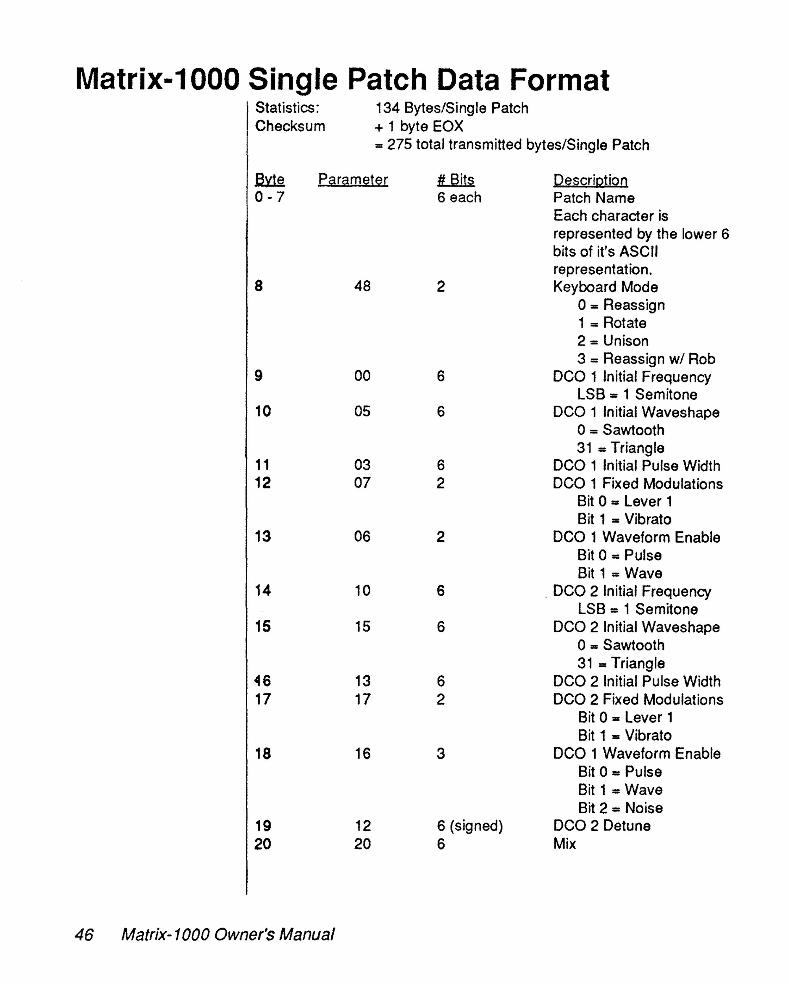
Matrix-1000 Single Patch Data FormatStatistics: 134 Bytes/Single PatchChecksum + 1 byte EaX
= 275 total transmitted bytes/Single Patch
~ Parameter li Bits DescriQtjoQ0-7 6 each Patch Name
Each character isrepresented by the lower 6bits of ifs ASCIIrepresentation.
8 48 2 Keyboard Mode0= Reassign1 = Rotate2 = Unison3 = Reassign w/ Rob
9 00 6 DCa 1 Initial FrequencyLSB = 1 Semitone
10 05 6 DCa 1 Initial Waveshape0= Sawtooth31 = Triangle
11 03 6 DCa 1 Initial Pulse Width12 07 2 DCa 1 Fixed Modulations
Bit 0 = Lever 1Bit 1 = Vibrato
13 06 2 DCa 1 Waveform EnableBit 0 = PulseBit 1 = Wave
14 10 6 . DCa 2 Initial FrequencyLSB = 1 Semitone
15 15 6 DCa 2 Initial Waveshape0= Sawtooth31 = Triangle
046 13 6 DCa 2 Initial Pulse Width17 17 2 DCa 2 Fixed Modulations
Bit 0 = Lever 1Bit 1 = Vibrato
18 16 3 DCa 1 Waveform EnableBit 0 = PulseBit 1 = WaveBit 2 = Noise
19 12 6 (signed) DCa 2 Detune20 20 6 Mix
46 Matrix-1000 Owner's Manual

.lMe paramete( Il BiJs QescriR1ÎQD.21 08 2 DCa 1 Fixed Modulations
Bit 0 .. PortamentoBit 1 .. Not used
22 09 1 DCa 1 Click23 18 2 Dca 2 Fixed Modulations
Bit 0 .. PortamentoBit 1 .. Keyboard Tracking
Enable24 19 1 DCa 2 Click25 02 2 Dca Sync Mode26 21 7 VCF Initial Frequency
LSB .. 1 Semitone27 24 6 VCF Initial Resonance28 25 2 VCF Fixed Modulations
Bit 0 .. Lever 1Bit 1 .. Vibrato
29 26 2 VCF Keyboard ModulationBit 0 .. PortamentoBit 1 .. Keyboard
30 30 6 VCF FM Initial Amount31 27 6 VCA 1 (Exponential) Initial Amount32 44 6 Portamento Initial Rate33 46 2 Lag Mode
o.. Constant Speed1 .. Constant Time2 .. Exponential3 .. Exponential
34 47 1 Legato Portamento Enable35 80 6 LFa 1 Initial Speed36 86 2 LFa 1 Trigger
0 .. No Trigger1 .. Single Trigger2 .. Multi Trigger3 .. External Trigger
37 87 1 LFa 1 Lag Enable38 82 3 LFa 1 Waveshape
(see Table 1)39 83 5 LF0 1 Retrigger point40 88 5 LFa 1 Sampled Source
Number41 84 6 LFa 1 Initial Amplitude42 90 6 LFa 2 Initial Speed
Matrix-1000 Owner's Manusl 47

~ Parameter ~ Descr,iQtioo.43 96 2 LFO 2 Trigger
See LFO 1 Triggersabove
44 97 1 LFO 2 Lag Enable45 92 3 LFO 2 Waveshape
(see Table 1)46 93 5 LFO 2 Retrigger point47 98 5 LFO 2 Sampied Source
Number48 94 6 LFO 2 Initial Amplitude49 57 3 Env 1 Trigger Mode
Bit a=ResetBit 1 =Multi TriggerBit 2 =External Trigger
50 50 6 Env 1 Initial Delay Time51 51 6 Env 1 Initial Attack Time52 52 6 Env 1 Initial Decay Time53 53 6 Env 1 Sustain Level54 54 6 Env 1 Initial Release Time55 55 6 Env 1 Initial Amplitude56 59 2 Env 1 LFO Trigger Mode
Bit 0 =GatedBit 1 =LFO Trigger
57 58 2 Env 1 ModeBit a= DADR ModeBit 1 =Free Run
58 67 3 Env 2 Trigger ModeSee Env 1 TriggerMode above
59 60 6 Env 2 Initial Delay Time60 61 6 Env 2 Initial Attack Time61 62 6 Env 2 Initial Decay TIme62 63 6 Env 2 Sustain Level63 64 6 Env 2 Initial Release Time64 65 6 Env 2 Initial Amplitude65 69 2 Env 2 LFO Trigger Mode
See Env 1 LFO TriggerMode above
66 68 2 Env 2 ModeSee Env 1 Modeabove
48 Matrix-1000 Owner's Manual

~ PaŒmete( 1t Bits Qescri.QtioQ67 77 3 Env 3 Trigger Mode
See Env 1 Trigger Mode above68 70 6 Env 3 Initial Delay Time69 71 6 Env 3 Initial Attack Time70 72 6 Env 3 Initial Decay Time71 73 6 Env 3 Sustain Level72 74 6 Env 3 Initial Release Time73 75 6 Env 3 Initial Amplitude74 79 2 Env 3 LFO Trigger Mode
(See Env 1 LFO Trigger Mode)75 78 2 Env3 Mode
(See Env 1 Mode)76 33 5 Tracking Generator Input Source
Code (See Table 2)77 34 6 Tracking Point 178 35 6 Tracking Point 279 36 6 Tracking Point 380 37 6 Tracking Point 481 38 6 Tracking Point 582 40 6 Ramp 1 Rate83 41 2 Ramp 1 Mode
o=Single Trigger1 =Multi Trigger2 =External Trigger3 =External Gated
84 42 6 Ramp2 Rate85 43 2 Ramp2 Mode
(See Ramp 1 Mode)86 01 7 (Signed) DCO 1 Freq. by LFO 1 Amount87 04 7 (Signed) DCO 1 PW by LFO 2 Amount88 11 7 (Signed) Dca 2 Freq. by LFO 1 Amount89 14 7 (Signed) DCO Z PW by LFO 2 Amount90 22 7 (Signed) VCF Freq. by Env 1 Amount91 23 7 (Signed) VCF Freq. by Pressure Amount92 28 7 (Signed) VCA 1 by Velocity Amount93 29 7 (Signed) VCA 2 by Env 2 Amount94 56 7 (Signed) Env 1 Amplitude by Velocity
Amount95 66 7 (Signed) Env 2 Amplitude by Velocity
Amount96 76 7 (Signed) Env 3 Amplitude by Velocity
Amount
Matrix-1000 Owner's Manual 49

~ Paramete~ .# Bits .DescriotioQ97 85 7 (Signed) LFO 1 Amp. by Ramp 1
Amount98 95 7 (Signed) LFO 2 Amp. by Ramp 2
Amount99 45 7 (Signed) Portamento Rate by
Velocity Amount100 31 7 (Signed) VCF FM Amount by Env 3
Amount101 32 7 (Signed) VCF FM Amount by
Pressure Amount102 81 7 (Signed) LFO 1 Speed by Pressure
Amount103 91 7 (Signed) LFO 2 Speed by Keyboard
Amount104 5 Matrix Modulation Bus 0
Source Code(see Table 2)
105 7 (Signed) MM Bus 0 Amount106 5 MM Bus 0 Destination
code (see Table 3)107 5 Matrix Modulation Bus 1
Source Code(see Table 2)
108 7 (Signed) MM Bus 1 Amount109 5 MM Bus 1 Destination
•
code (see Table 3)110 5 Matrix Modulation Bus 2
Source Code(see Table 2)
111 7 (Signed) MM Bus 2 Amount112 5 MM Bus 2 Destination
code (see Table 3)113 5 Matrix Modulation Bus 3
Source Code(see Table 2)
114 7 (Signed) MM Bus 3 Amount115 5 MM Bus 3 Destination
code (see Table 3)116 5 Matrix Modulation Bus 4
Source Code(see Table 2)
117 7 (Signed) MM Bus 4 Amount
50 Matrix-1000 Owner's Manual
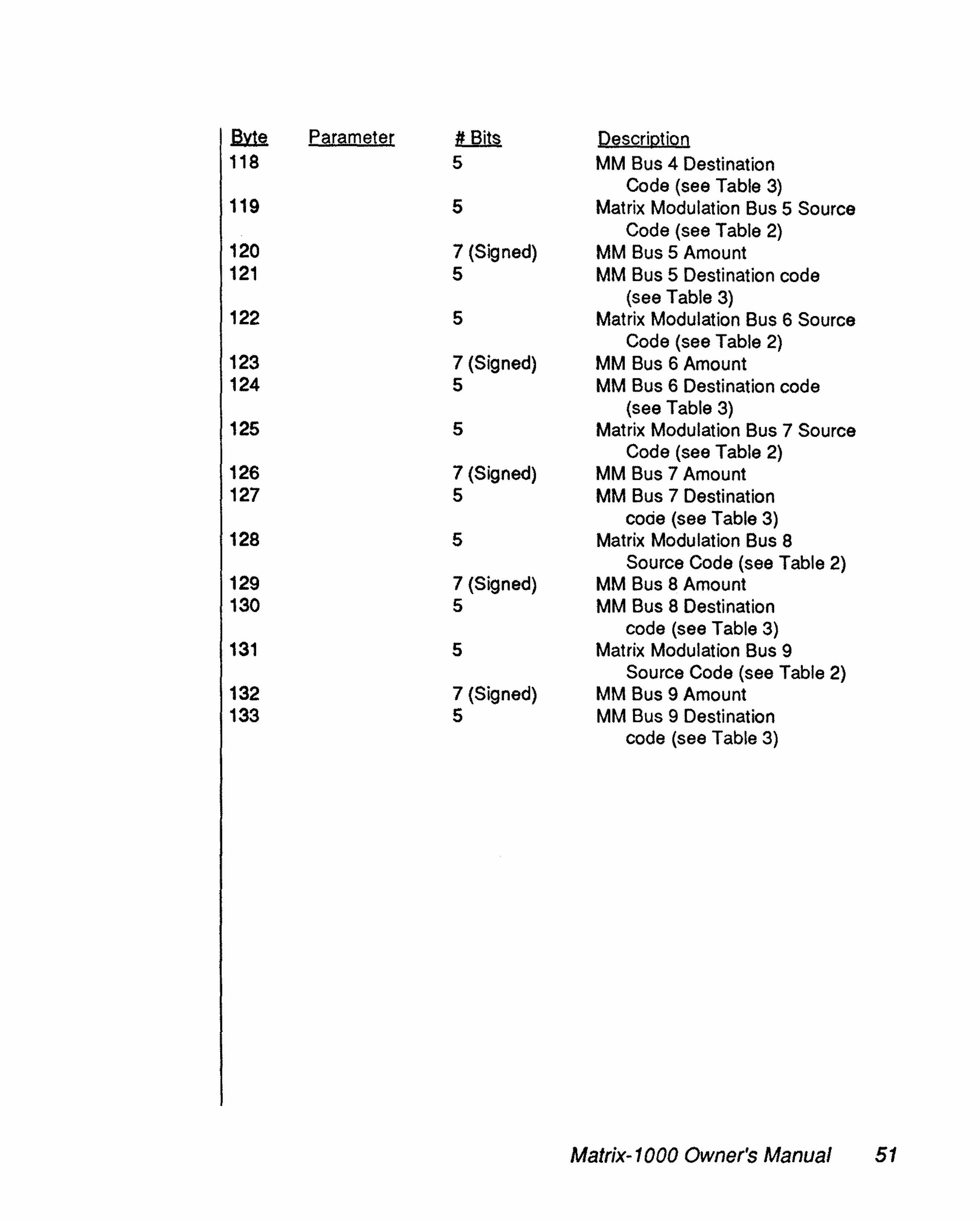
~ Earametet ttlill.§. DescriQtjQQ118 5 MM Bus 4 Destination
Code (see Table 3)119 5 Matrix Modulation Bus 5 Source
Code (see Table 2)120 7 (Signed) MM Bus 5 Amount121 5 MM Bus 5 Destination code
(see Table 3)122 5 Matrix Modulation Bus 6 Source
Code (see Table 2)123 7 (Signed) MM Bus 6 Amount124 5 MM Bus 6 Destination code
(see Table 3)125 5 Matrix Modulation Bus 7 Source
Code (see Table 2)126 7 (Signed) MM Bus 7 Amount127 5 MM Bus 7 Destination
code (see Table 3)128 5 Matrix Modulation Bus 8
Source Code (see Table 2)129 7 (Signed) MM Bus 8 Amount130 5 MM Bus 8 Destination
code (see Table 3)131 5 Matrix Modulation Bus 9
Source Code (see Table 2)132 7 (Signed) MM Bus 9 Amount133 5 MM Bus 9 Destination
code (see Table 3)
Matrix-1000 Owner's Manual 51

Table 1
LFO Wave Codes
0= Triangle1 = Up Sawtooth2 = Down Sawtooth3 = Square
Table 2
4 = Random5 = Noise6 = Sampied Modulation7 ,;. Not Used
Modulation Source CodesTracking Generator Inputs
Unused Modulations must have their Sourcesand Destinations set to O.
1 = Envelope 12 = Envelope 23 = Envelope 34 = LFO 15 = LFO 26 = Vibrato7 = Ramp 18 = Ramp29 = Keyboard
10 = Portamento
0= Unused Modulation"11 = Tracking Generator12 = Keyboard Gate13 = Velocity14 = Release Velocity15 = Pressure16 = Pedal117 = Pedal218 = Lever 119 = Lever 220 = Lever 3
" The "0 = Unused Modulation" parameter in thisTable is found in the Modulation Source Iist only. Thisparameter is not a Tracking Generator input and thuswHI not be displayed in parameter 33 TRACK INPUT.
52 Matrix-1000 Owner's Manual
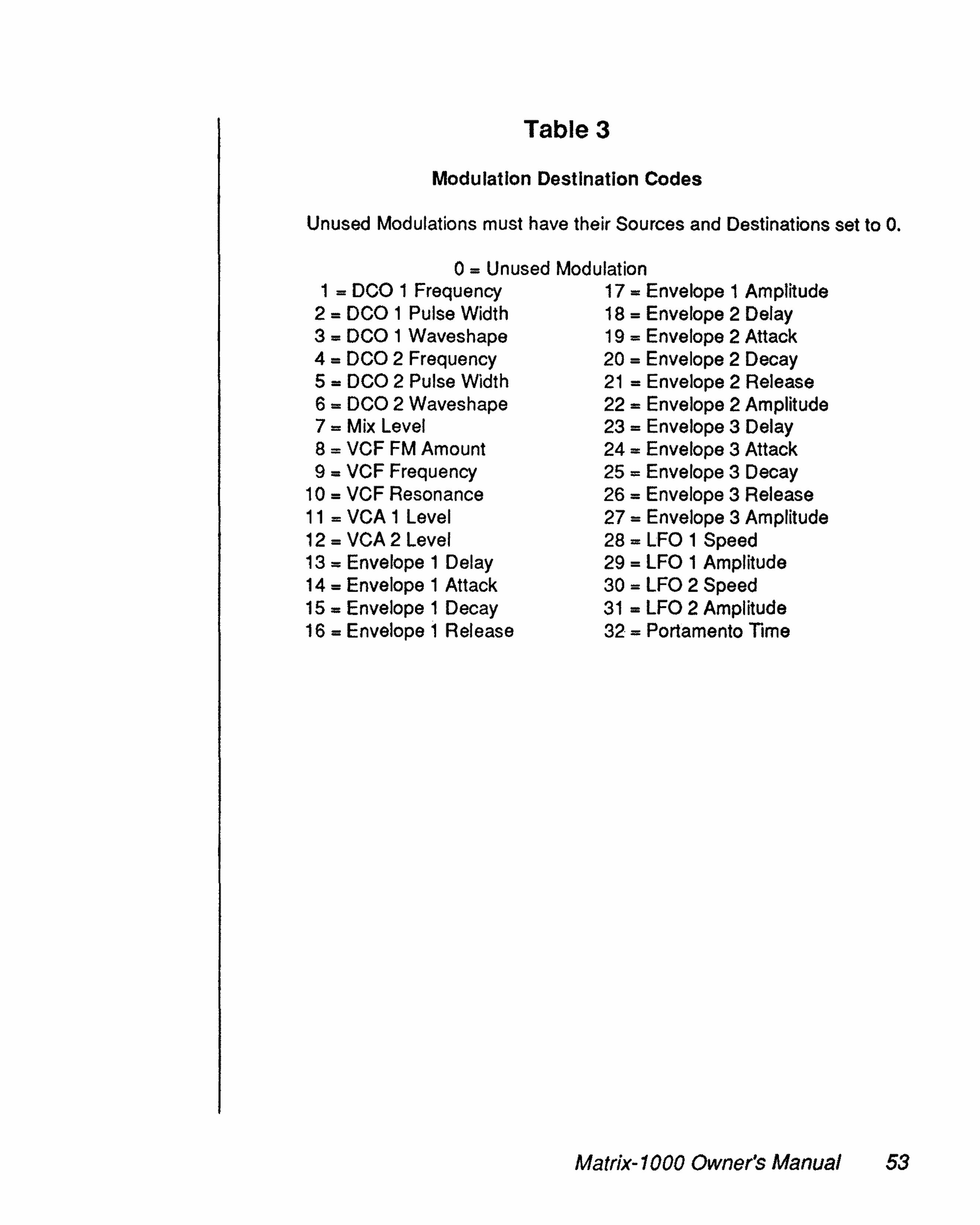
Table 3
Modulation Destination Codes
Unused Modulations must have their Sources and Destinations set ta O.
o= Unused Modulation1 = DCO 1 Frequency
2 = DCO 1 Pulse Width3 = DCO 1 Waveshape4 = DCO 2 Frequency5 = DCO 2 Pulse Width6 = DCO 2 Waveshape7 = Mix Level8 = VCF FM Amount9 = VCF Frequency
10 = VCF Resonance11 = VCA 1 Level12 = VCA 2 Level13 = Envelope 1 Delay14 = Envelope 1 Attack15 = Envelope 1 Decay16 = Envelope 1 Release
17 = Envelope 1 Amplitude18 = Envelope 2 Delay19 = Envelope 2 Attack20 = Envelope 2 Decay21 = Envelope 2 Release22 = Envelope 2 Amplitude23 = Envelope 3 Delay24 = Envelope 3 Attack25 = Envelope 3 Decay26 = Envelope 3 Release27 = Envelope 3 Amplitude28 = LFO 1 Speed29 = LFO 1 Amplitude30 = LFO 2 Speed31 = LFO 2 Amplitude32 = Portamento Time
Matrix-1000 Owner's Manual 53

Matrix-1000 Global Parameters Data FormatStatistics: 172 bytes/Global Parameters
.. 344 nybbles transmitted + 5 bytes Header+ 1 byte Checksum + 1 byte EOX
.. 351 total transmitted bytes/Global parameters
~ tt Bit~ DescriQtion0 Not Used1 6 Vibrato Speed2 2 Vibrato Speed Mod Source Code3 6 Vibrato Speed Modulation Amount4 3 Vibrato Waveform5 6 Vibrato Amplitude6 2 Vibrato Amp Mod Source Code7 6 Vibrato Amp Modulation Amount8 6 (Signed) Master Tune9 Not Used10 Not Used11 4 MIDI Basic Channel12 1 MIDI OMNI Mode Enable13 1 MIDI Controllers Enable14 1 MIDI Patch Changes Enable15 Not Used16 Not Used17 7 MIDI Pedal 1 Controller18 7 MIDI Pedal 2 Controller19 7 MIDI Lever 2 Controller20 7 MIDI Lever 3 Controller21-31 Not Used32 1 MIDI Echo Enable34 6(signed) Master Transpose35 1 MIDI Mono Mode Enable36-161 1 each Group Enables
(One bit per patch, LS bit first)162-163 Not Used164 1 Bend Range165 1 Bank Lock Enable (In MSB only)166 1 Number of Units (Group Mode)167 1 Current Unit Number (Group Mode)168 1 Group Mode Enable (In MSB only)169 1 Unison Enable170 1 Volume Invert Enable171 1 Memory Protect Enable
54 Matrix-1000 Owner's Manual
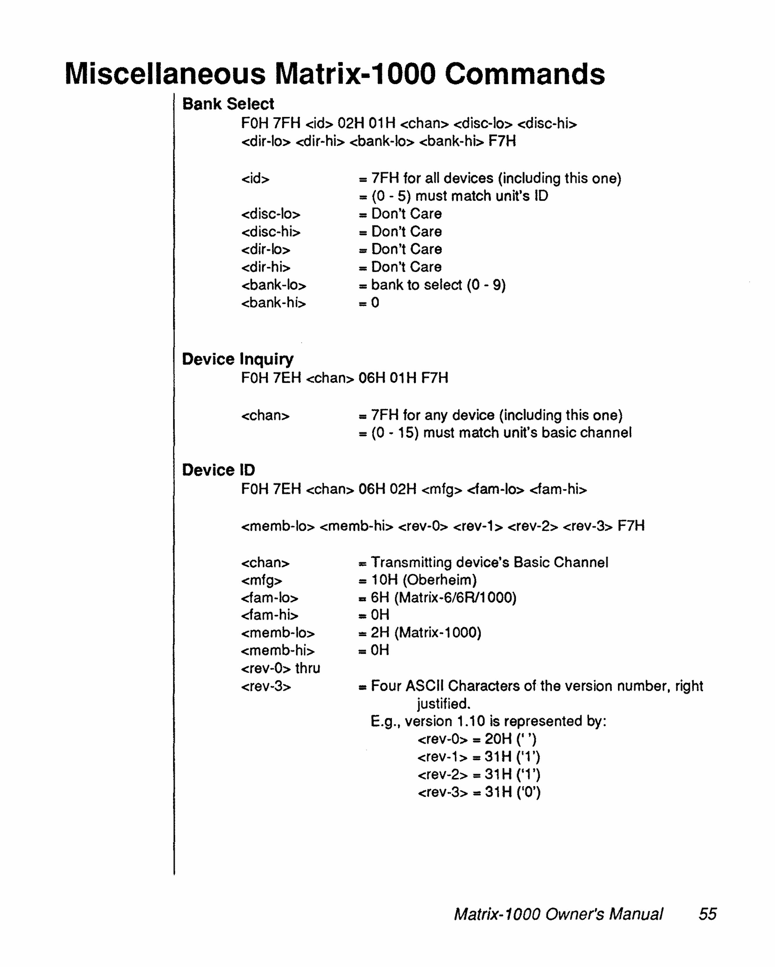
Miscellaneous Matrix-1000 CommandsBank Select
FOH 7FH <id> 02H 01 H <chan> -edlsc-los -edlsc-hb-edir-lœ- -edlr-hb- -ebank-lœ- <bank-hi> F7H
<id>
-edisc-lœ--cdisc-hb--cdir-lœ--edir-hb-«bank-los,<bank-hi>
= 7FH for ail devices (including this one)= (0 - 5) must match unit's ID= Don't Care= Don't Care= Don't Care= Don't Care= bank to select (0 - 9)=0
Deviee InquiryFOH 7EH <chan> 06H 01 H FlH
<chan> = 7FH for any device (including this one)= (0 - 15) must match unit's basic channel
Deviee IDFOH 7EH <chan> 06H 02H <mfg> <fam-Io> <fam-hi>
-ememb-los -crnernb-hb- <rev-O> -erev-t» <rev-2> <rev-3> F7H
<chan><mfg>-darn-lœ--darn-hb--ememb-lo»-emernb-hb--erev-O» thru<rev-3>
= Transmitting device's Basic Channel= 10H (Oberheim)= 6H (Matrix-6/6R11000)=OH=2H (Matrix-1000)=OH
= Four ASCII Characters of the version number, rightjustified.
E.g., version 1.10 is represented by:erev-o» = 20H (' ')-erev-t» = 31 H ('1 ')<rev-2> = 31 H ('1')<rev-3> = 31 H ('0')
Matrix-1000 Owner's Manua/ 55

Active Controllers
01 Vibrato Amount (Lever 2)02 Breath Control (Lever 3)04 Foot Pedal (Pedal 1)06 Data Entry07 Volume31· Bank Change Enable64 Sustain (Pedal 2)96 Increment97 Decrement98 Non-Reg Parm LSB99 Non-Reg Parm MSB100 Reg Parm LSB101 Reg Parm MSB
Registered Parameters
00 Pltch Bend Range (In semitones)01 Fine Tune (in 128ths of a semitone)02 Transpose (In semltones)
Non-registered parameters may be used to control any parameter byusing the front panel parameter number. Matrix modulations must becontrolled by use of the System Exclusive message. When usingregistered or non-registered parameter editing, ail received data entrycontroller values are offset by 40H, except when the currently selectedparameter is the registered pitch bend range. Thus, a data entry valueof 40H will update the selected parameter to be O. while 3EH is interpreted as -2. This allows for transmission of negative numbers.
56 Matrix-1000 Owner's Manual

Chapter6:
WARRANTY
If Vou Have A ProblemThe staff at ECC/Oberheim wish to thank Vou for purchasing an Oberheim product, and we hope that vou will remain a long-time Oberheimplayer. We are confident that your instrument will provide vou with yearsof excellent service, as each unit is thoroughly tested and inspectedbefore it leaves the factory. The Owner's Manual was written to be logicaland comprehensive, so that vou will be able to get the most out of yourOberheim.
Although we have taken great care in manufacturing your Oberheiminstrument and preparing thorough documentation in the manual, products at this level of technology may require servicing. The followingWarranty Policy outlines your rights and responsibilities, and also Iistsseverallimitations of coverage and important exclusions. We stronglyrecommend that vou read the following policy statements carefully andrefer to the procedure at the end in obtaining service for your Oberheimproduct should it ever be needed.
OBERHEIM L1MITED CUSTOMER WARRANTY(Non-Transferable)
Oberheim, a Division of ECC Development Corporation, warrants itsproducts, when purchased in the United States of America from ar.Authorized Oberheim Dealer, to be free from defects in materials orworkmanship for a period of 12 months from the date of purchase.Warranty service is effective and available to the original purchaserONLY, and only upon completion and return of the Oberheim WarrantyRegistration card within 14 days of the date of purchase.
Warranty coverage is valid for Factory-Authorized updates to Oberheimproducts when their installation is performed by an ECC/OberheimAuthorized Service Center and a properly completed Warranty Certificateis returned to the factory within 14 days of installation.
To obtain service under this Warranty, the product must, upon discoveryof the defect, be properly packed and shipped to the nearest OberheimAuthorized Service Center. The party requesting Warranty service must
Matrix-1000 Owner's Manual 57

provide proof of original ownership and date of purchase of theproduct, or date of installation of the update, by supplying to theOberheim Authorized Service Center either the Warranty Registration Sticker applied to the unit itself, or the sales receiptlinstallation receipt. In the event that bath have been lost ormisplaced, the Service Center shall, at the Service Center's orowner's expense, contact Oberheim to verify the Warranty statusof the product.
If the Warranty has been verified, Oberheim will, without chargefor parts or labor, either repair or replace the defective part(s). Ifthe Warranty cannot be verified, the entire cost of the repair inparts and labor is the responsibility of the product's owner.
PRICES AND SPECIFICATIONS ARE SUBJECT TO CHANGEWITHOUT NOTICE
WHAT 18 COVERED
ECC/Oberheim warrants that it will make ail necessary adjustments, repairs or replacements at no cost to the original ownerwithin the first 12 months from the purchase date if:
1. The product fails to perform its specified functions due tofailure of one or more of its components.
2. The product fails to perform its specified functions due todefects in workmanship.
3. The product is maintained and operated by the owner instrict accordance with the written instructions for propermaintenance and use as specified in the Owner'sManual.
58 Matrix-1000 Owner's Manual

WHAT 18 NOT COVERED
Before purchasing and using, the owner shall determine the suitability ofthe product for hislher intended use, and the owner assumes ail risk andIiability whatsoever in connection therewith. Oberheim shall not be Iiablefor any injury, loss or damage, direct or consequential, arising out of theproduct owner's use or inability to use the product.
The Warranty provides only the benefits specified and does not coyerdefects or repairs needed as a result of acts beyond the control ofOberheim including but not Iimited to:
1. Damage caused by abuse, accident or negligence.
2. Any tampering, alteration or modification of the product's mechanical or.electronic components.
3. Failure to operate the product in strict accordance with theprocedures written in the Owner's Manual.
4. Repairs performed by unauthorized persons.
5. Damage caused by fire, smoke, falling objects, water orIiquids,etc., or natural events such as rain, earthquakes, floods,Iightning, tornadoes, storms, etc.
6. Damage caused by operation on improper voltages.
IMPORTANT NOTICE: The warranty is VOID if the product iselectronically or mechanically modified, altered oltamperedwith in any way.
Oberheim shall not be Iiable for costs involved in packing or preparingthe product for shipping with regards to time, telephone cali charges,labor or materials, shipping and freight costs, or time and expensesinvolved in transporting the product to and from an Oberheim AuthorizedService Center, an Oberheim Authorized Dealer or the Oberheim Factory. If a suitable shipping container ls unavailable, a replacement cartonmay be purchased from Oberheim.
Matrix-1000 Owner's Manual 59

ECC/Oberheim will not cover under Warranty an apparentmalfunction that is determined to be in fact user error, or theowner's inability to use the product.
ECC/Oberheim will not cover under Warranty an apparentmalfunction that is inaccurately or inadequately described by theowner to the Service Center at the time of repair.
THE DURATION OF ANY OTHER WARRANTIES, WHETHERIMPLIED OR EXPRESS, INCLUDING BUT NOT L1MITED TOTHE IMPLIED WARRANTY OF MERCHANTABILlTY, ISL1MITED TO THE DURATION OF THE EXPRESS WARRANTYHEREIN.
ECC/Oberheim hereby excludes incidental and consequentialdamages, including but not Iimited to:
1. Loss of time
2. Inconvenience
3. Delay in performance of the Warranty
4. The loss of use of the product
5. Commercial loss
6. Breach of any express or implied warranty, including theImplied Warranty of Merchantability, applicable to thisproduct.
Oberheim shall not be Iiable for damage or loss resulting fromthe negligent or intentional acts of the shipper or his contractaffiliates. The owner of the product should contact the shipper forproper claims procedures in the event of damage or loss resulting from shipment.
60 Matrix-1000 Owner's Manual
HOWTO OBTAIN WARRANTY SERVICE
If you have reason to believe that your Oberheim product is malfunctioning or otherwise not operating properly, do the following:
STEP 1: CONTACT VOUR NEAREST ECC/OBERHEIMAUTHORIZED SERVICE CENTER
Telephone them as soon as the problem is discovered. Be preparedto discuss the problem as completely and accurately as possible. Acurrent roster of Authorized Service Centers is included with theOwner's Manual.
The Service Center will let you know when the repair can be scheduled, the approximate number of days it will take to complete therepair and if the required parts are in stock or if they need to beordered.
Take the failed unit to the Service Center along with the sales receiptas the Service Center will need to verify the Warranty. If you havereturned your Warranty Card, the Warranty Verification Stickeraffixed to the bottom panel of your unit is sufficient to prove warrantystatus.
The Service Center will then inspect the product and take the necessary steps to complete the repair.
If the product continues to malfunction or another problem differentfrom the original problem occurs, contact the service center IMMEDIATELY so that the problem can be resolved without delay or furthercomplications.
STEP 2. CONTACT VOUR ECC/OBERHEIM DEALERIf you feel that your problem has not been resolved, contact theOberheim Dealer where the product was purchased. It will be mostexpedient if you discuss the matter personally with the salespersonwho sold you the instrument. By making the salesperson aware ofyour situation, he or she will be in a better position to assist you ingetting the problem resolved.
Matrix-1000 Owner's Manual 61

STEP 3: WRITE TO THE ECC/OBERHEIM NATIONALOFFICES
If you believe that the problem is still unresolved after youhave contacted the Service Center and Dealer, contact theECC/Oberheim National Offices. In an atterript to resolveyour problem, we will work with your local Service Center orDealer to review and verify the information and facts. Basedon these tacts, we will advise or consult with the ServiceCenter or Dealer as appropriate.
Written correspondence should be addressed to:
OBERHEIMA Division of ECC Development CorporationCustomer Services Department2015 Davie Ave.City of Commerce, CA 90040-1704
Every attempt will be made to respond to your letter asquickly as possible.
62 Matrix-1000 Owner's Manual

•
-
•
scanned at www.wolzow.com