mathematical modelling and experimental … mathematical modeling of the solid conversion. in rotary...
TRANSCRIPT

IT3’05 Conference, May 2005, Texas, USA
1
MATHEMATICAL MODELLING AND EXPERIMENTAL INVESTIGATION OF THE PYROLYSIS OF WASTE IN ROTARY KILNS
M. Beckmann, Bauhaus-Universität Weimar, A. Fontana, Universite Libre de Bruxelles,
and H. Gehrmann, Clausthaler Umwelttechnik-Institut
ABSTRACT Pyrolysis processes are used in the field of the thermal treatment of waste e.g. as a process unit in combination with a gasification or combustion unit realized in the RT21 process in Japan from Mitsui. Furthermore pyrolysis processes are used for specially prepared waste fractions as a thermal pre-treatment unit, e.g. before a power station in the Con-Therm process in Germany or in the steel and cement industry. In principle there is also the possibility to use pyrolysis for the direct recycling of materials such as Plexiglass or plastics reinforced with carbon fibres. Often rotary kilns are used in the field of pyrolysis. The lumpy starting material is mixed due to the rotation of the rotary kiln. The energy for the pyrolysis can be given to the starting material indirectly, e.g. through radiant tubes from an external heater, to the rotary kiln wall or directly through a hot gas flow. The starting material is converted through the steps of drying, release and conversion of volatile components to a pyrolysis coke and pyrolysis gas. To optimize existing plants or to design new ones mathematical models are important tools to minimize the experimental effort. In order to be able to describe the pyrolysis process in a rotary kiln using a mathematical model, the transport of the solid and the specific conversion processes dependent upon the constructive parameters such as diameter and length of the rotary kiln as well as operating parameters such as angle of inclination, rotational frequency, throughput and course of the temperature over the length in the rotary kiln must be described. For process models which describe such processes in a reactor, it can usually be distinguished between a reactor model and a so-called basic model. The behavior of the solid in the reactor (residence time behavior) is described using the reactor model and the material and heat transfer as well as the conversion process with the help of the basic model. In the following a mathematical model which considers on the one hand side the residence time behaviour and on the other hand the heat and material transfer mechanisms (basic model), including unsteady behaviour, is presented. This paper shows a mathematical model and its validation for an homogenous material, such as sand, without and with solid conversion of polyethylene and substitute fuels including the evaporation and drying process.

IT3’05 Conference, May 2005, Texas, USA
REACTOR MODEL The behavior of the solid, also referred to as the residence time behavior or as reactor behavior in connection with the apparatus, has a significant influence on the course of the conversion over the reactor length. Therefore, the residence time behavior and the main influencing parameters for the control of the residence time behavior are of great importance for the optimization of the overall process. The description of the residence time behavior also forms a fundamental basis for the mathematical modeling of the solid conversion. In rotary kiln systems constructive parameters, such as rotary kiln radius R and kiln length L, and operating parameters, such as mass flow , angle of inclination β, and rotary kiln speed n, are important with regard to the residence time behavior (Figure 1).
Fm&
The residence time behavior is also influenced by the characteristics of the starting materials, e.g. composition, bulk density ρF, angle of repose αo, particle-size distribution, etc.
Fig. 1: Main influencing parameters for the material transport Generally, the residence time behavior is characterized through the residence time distribution E (Θ) [1] and the derived average residence time τ. In rotary kiln systems in particular, the residence time behavior can be described using path-dependent values such as filling height h (x), angle of bed inclination ψ (x) and the filling angle ε(x). The residence time model delivers the following parameters for the total process model: The course of the filling angle ε (x) (Figure 1) with the derived values of filling height h (x), degree of filling φ (x) and the corresponding portions of the area covered with solid, the surface of the solid facing the gas and the free wall area, which is necessary for the heat transfer as well as the average residence time τ, as well as individual residence times ∆ti for each stirred vessel element i (Continuously Stirred Reactor- element, CSR – element).
2

IT3’05 Conference, May 2005, Texas, USA
The course of the filling angle for an unknown starting material can be determined according to the model from Hogg, Shoji and Austin [2] with few cold investigations of the residence time using the following equations:
∫=
⎥⎦
⎤⎢⎣
⎡⎟⎠⎞
⎜⎝⎛ ⋅
⋅−⋅−−
⋅⋅=⎟
⎠⎞
⎜⎝⎛ ⋅ )(
)0(5,0
3263
2
sin21sinsin
sinz
z
MCM
dMR
zM ε
ε εεε
εε (Eq.1),
with ⎟⎟⎟
⎠
⎞
⎜⎜⎜
⎝
⎛ ⋅=
KmM S&2 and (Eq.2),
⎟⎟⎠
⎞⎜⎜⎝
⎛=
0costan
αβC (Eq.3),
as well as (Eq.4), 03 cot23/2 απρ ⋅⋅⋅⋅⋅⋅⋅= RnBK s
Sm& mass flow of the solid [kg/h]
β angle of inclination of the rotary kiln [°] α0 angle of repose [°] ρS bulk density of the solid [kg/m3] n rotational frequency of the rotary kiln [min-1] R radius of the rotary kiln [m] ε half of the filling angle [°rad] z variable over the length of the rotary kiln, starting at the discharge [m] B material factor, must be determined experimentally [-].
The equations (1) to (4) are only valid for low degrees of filling. The material factor B in this equation is an experimentally determined dimensionless material parameter which physically describes the ratio of the residence time of a particle on the surface to the total residence time for a cycle in the bed and on the surface. For sand a material factor B was determined to 0.70. For heterogeneous materials, as substitute fuels are, to which the material factor during pyrolysis processes could not be determined easily, B is assumed to be 1. To compensate the failure with regard to the residence time the main influencing parameters bulk density and bottoming angle are calculated in dependeny of the material conversion. In one hot test the average residence time was measured by stones which were put into the mass flow. When the stones fell into the discharge of the rotary kiln the time was measured. Calculating the residence time with B assumed to be 1 gives a failure of a maximum up to 25 %.
3

IT3’05 Conference, May 2005, Texas, USA
BASIC MODEL In rotary kiln reactors the heat transfer to the bed takes place either
• directly through a heated inert or combustion gas or • indirectly through an external heater.
The type of energy input depends upon the respective process carried out. For example, the heat for the endothermic calcination of raw material is transferred through a hot gas. For process under inert atmosphere, such as pyrolysis, the energy is usually introduced from the outside, e.g. electrically or via internal gas-heated radiating pipes. The partial processes radiation, convection and conduction are coupled with one another in the type of heat transfer. The material conversion processes also play a role in the energy balance. In order to couple the material conversion processes with the heat transfer and for the determination of heat transfer surfaces for gas, wall and solid, information concerning the solid transport and the residence time are required. The basic model developed here is based on the mass- and energy balances (see Figure 2 and Figure 3). The description of the solid transport gives rise to a maximum gradient model, i.e. only the change over the length of the rotary kiln is considered, not over the bed height. A small stirred vessel element with the mass mS(t) from the point of view of an “observer riding along” is regarded for the conversion processes. The CSR- element is situated at a certain position ∆x along the longitudinal direction of the rotary kiln after a certain residence time dt. At this position, the stirred vessel element undergoes material and energy exchange with the gas atmosphere flowing above and energy exchange with the wall of the rotary kiln. Dependent upon the temperature, the mass dms is transferred from the surface to the gas flowing above it in a certain time period dt.
Fig. 2: Mass flows in a CSR- element
4

IT3’05 Conference, May 2005, Texas, USA
The mass balance for the gas:
0,, =−+∆− xGS
xxG mdt
dmm && , (Eq.5)
and for the solid:
∫−=t
RS dttmmtm0
0 )()( & , (Eq.6)
with
( )dt
dmtm SR =& (Eq.7)
From the kinetics is determined by an Arrhenius equation. ( )tmR&
Following Figure 3 shows the heat and enthalpy flows in a CSR– element.
Fig. 3: Heat flows in a CSR-element
The changing of the solid’s enthalpy is equal to the sum input and discharge as well as formation/consumption.
VW
RS
SGSGWSSchWSS h
dtdmh
dtdmQQQQ
dtdH
∆⋅−∆⋅−−−+= εαε ,,,,&&&& (Eq.8)
SchWS,Q& Heat flow from the wall on the side of the bulk material into the solid due to radiation and conduction [W],
5

IT3’05 Conference, May 2005, Texas, USA
εWS,Q& Heat flow from the wall opposite the solid due to radiation under consideration of the secondary radiation of the gas [W],
εSG,Q& Heat flow from the solid into the gas due to radiation under consideration of the secondary radiation of the opposite wall [W],
αSG,Q& Heat flow from the solid into the gas through convection [W],
Rh∆⋅dt/dmS consumption of heat due to material conversion [W],
Vh∆⋅dt/dm W consumption of heat due to evaporation and drying [W]. The gas mass flow is assumed to be as steady-state:
xGWGSGSGSGxxGG HQQQHH
dtdH
,,,,,0 &&&&&& −++++== +∆− εααε (Eq.9),
with
x-xG, ∆H& enthalpy flow from the last CSR- element [W],
xG,H& enthalpy flow from the actual CSR- element [W],
SGH& enthalpy flow from conversion, evaporation and drying [W],
εα +WG,Q& Heat flow from the wall into the gas due to radiation and conduction [W].
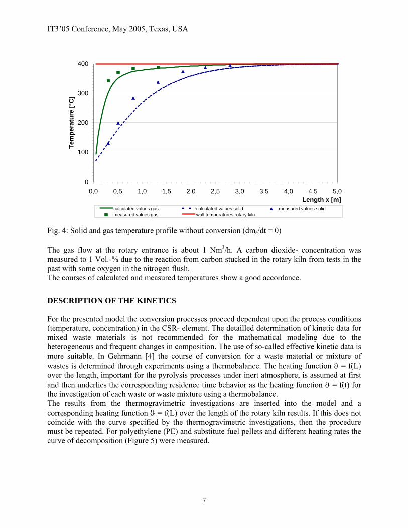
The evaporation of water during the heating of the solid is modelled with the formulars according to the analogy of heat and material transport mechanism. The drying process is calculated with the help of Gauss error- function [3]. With the reactor model from Austin and the described basic model a calculation for the solid and the gas temperatures for sand at 400 °C wall temperature was performed. Figure 4 shows the calculated and measured solid and gas temperature profiles for sand without conversion.
6
IT3’05 Conference, May 2005, Texas, USA
0
100
200
300
400
0,0 0,5 1,0 1,5 2,0 2,5 3,0 3,5 4,0 4,5 5,0Length x [m]
Tem
pera
ture
[°C
]
calculated values gas calculated values solid measured values solidmeasured values gas wall temperatures rotary kiln
Fig. 4: Solid and gas temperature profile without conversion (dms/dt = 0) The gas flow at the rotary entrance is about 1 Nm3/h. A carbon dioxide- concentration was measured to 1 Vol.-% due to the reaction from carbon stucked in the rotary kiln from tests in the past with some oxygen in the nitrogen flush. The courses of calculated and measured temperatures show a good accordance. DESCRIPTION OF THE KINETICS For the presented model the conversion processes proceed dependent upon the process conditions (temperature, concentration) in the CSR- element. The detailled determination of kinetic data for mixed waste materials is not recommended for the mathematical modeling due to the heterogeneous and frequent changes in composition. The use of so-called effective kinetic data is more suitable. In Gehrmann [4] the course of conversion for a waste material or mixture of wastes is determined through experiments using a thermobalance. The heating function ϑ = f(L) over the length, important for the pyrolysis processes under inert atmosphere, is assumed at first and then underlies the corresponding residence time behavior as the heating function ϑ = f(t) for the investigation of each waste or waste mixture using a thermobalance. The results from the thermogravimetric investigations are inserted into the model and a corresponding heating function ϑ = f(L) over the length of the rotary kiln results. If this does not coincide with the curve specified by the thermogravimetric investigations, then the procedure must be repeated. For polyethylene (PE) and substitute fuel pellets and different heating rates the curve of decomposition (Figure 5) were measured.
7

IT3’05 Conference, May 2005, Texas, USA
0
10
20
30
40
50
60
70
80
90
100
50 100 150 200 250 300 350 400 450 500 550 600 650 700 750 800Temperature [°C]
Mas
s-fr
actio
n m
/m0 [
%]
PE-10 °K/min PE-50 °K/minPE-100 °K/min substitute fuel - technical thermobalance
Substitute fuel 20 °K/min
PE 10 °K/min
PE 50 °K/min
PE 100 °K/min
Fig. 5: Result from an investigation with the thermobalance with different materials and heating rates With increasing the heating rate for PE from 10 °K/min to 100 °K/min the start of decomposition is shifted from 450 °C to higher temperatures at 530 °C due to a thermal slowness of the sample. The decomposition of the substitute fuel was measured at a technical thermobalance. The first decomposition starts here at a temperature about 250 °C. The substantial decomposition starts at 400 °C. These curve could be approached by these function:
n
TREk
dtd )1()(exp αα
−⋅⎥⎦⎤
⎢⎣⎡
⋅−⋅= ∞ [1/s], [5] (Eq.10),
with ∞−
−=
mmtmm
0
0 )(α [-] (Eq.11).
m0 mass at the time t = 0, m(t) actual mass at the time t and m∞ mass at the time t = tfinish.
The kinetic data E, k∞ and n are determined with the help of Gauss minization of square deviations. The determination of the kinetic data from the thermoblalance is very important for the calculation of the decomposition of the solid. Often exact results from the measurements or the calculation of the data of the thermobalance are not available. It could be shown that only with a difference of e.g. 30 °C in the temperature range of the measured data from the thermobalance
8
IT3’05 Conference, May 2005, Texas, USA
the determined kinetic data change the temperature profiles of the solid and gas in the calculation for the rotary kiln noticeable. Then follows for the material conversion ∆mS/∆t with the mass flow m0 as actual mass flow into the first stirred vessel element and m∞ as mass flow out of the rotary kiln:
n
SS
tmtm
ttmtmTR
Ektmtmt
m⎥⎥
⎦
⎤
⎢⎢
⎣
⎡
∆⋅−∆⋅
∆⋅−∆⋅−⋅⎥⎦
⎤⎢⎣⎡
⋅−⋅⋅∆⋅−∆⋅=
∆∆
∞∞
∞∞∞
)(
))((1(exp)(00
0000
&&
&&&& [kg/s] (Eq.12)
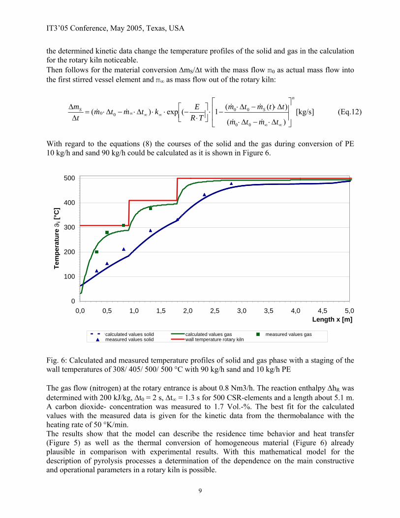
With regard to the equations (8) the courses of the solid and the gas during conversion of PE 10 kg/h and sand 90 kg/h could be calculated as it is shown in Figure 6.
0
100
200
300
400
500
0,0 0,5 1,0 1,5 2,0 2,5 3,0 3,5 4,0 4,5 5,0Length x [m]
Tem
pera
ture
ϑi [
°C]
calculated values solid calculated values gas measured values gasmeasured values solid wall temperature rotary kiln
Fig. 6: Calculated and measured temperature profiles of solid and gas phase with a staging of the wall temperatures of 308/ 405/ 500/ 500 °C with 90 kg/h sand and 10 kg/h PE The gas flow (nitrogen) at the rotary entrance is about 0.8 Nm3/h. The reaction enthalpy ∆hR was determined with 200 kJ/kg, ∆t0 = 2 s, ∆t∞ = 1.3 s for 500 CSR-elements and a length about 5.1 m. A carbon dioxide- concentration was measured to 1.7 Vol.-%. The best fit for the calculated values with the measured data is given for the kinetic data from the thermobalance with the heating rate of 50 °K/min. The results show that the model can describe the residence time behavior and heat transfer (Figure 5) as well as the thermal conversion of homogeneous material (Figure 6) already plausible in comparison with experimental results. With this mathematical model for the description of pyrolysis processes a determination of the dependence on the main constructive and operational parameters in a rotary kiln is possible.
9

IT3’05 Conference, May 2005, Texas, USA
For a mixture polyethylene, water and sand a calculation and an experiment were done as it is shown in Figure 7.
0
100
200
300
400
500
0,0 0,5 1,0 1,5 2,0 2,5 3,0 3,5 4,0 4,5 5,0Length x [m]
Tem
pera
ture
ϑi [
°C]
0
0,01
0,02
0,03
0,04
0,05
0,06
0,07
0,08
0,09
moi
stur
e in
the
solid
[Mas
s-fr
actio
n]
calculated values solid calculated values gas measured values solidmeasured values gas wall temperatures rotary kiln moisture in the solid
Fig. 7: Calculated and measured temperature profiles of solid and gas phase with a staging of the wall temperatures of 295/ 410/ 504/ 510 °C with 59 kg/h sand, 6 kg/h water and 10 kg/h of PE The gas flow (nitrogen) at the rotary entrance is about 1.3 Nm3/h. The reaction enthalpy ∆hR was determined with 200 kJ/kg, ∆t0 = 7.6 s, ∆t∞ = 5.5 s for 400 CSR-elements and a length about 5.1 m. When the solid reaches the boiling temperature the drying of the solid begins. The solid temperature remains at 100 °C and increases when the solid is nearly dried. The profiles show a good accordance between calculated and measured values. For the substitute fuel with a mass flow about 22.5 kg/h a calculation and an experiment were done as it is shown in Figure 8.
10

IT3’05 Conference, May 2005, Texas, USA
0
100
200
300
400
500
600
0,0 0,5 1,0 1,5 2,0 2,5 3,0 3,5 4,0 4,5 5,0Length x [m]
Tem
pera
ture
ϑi [
°C]
0
2
4
6
8
10
12
14
16
18
mas
s flo
w o
f vol
atile
s [k
g/h]
calculated values solid calculated values gasmeasured values solid measured values gaswall temperatures rotary kiln mass flow of volatiles
Fig. 8: Calculated and measured temperature profiles of solid and gas phase for 22.5 kg/h of substitute fuel The gas flow (nitrogen) at the rotary entrance is about 1 Nm3/h. The reaction enthalpy ∆hR was determined with 350 kJ/kg, ∆t0 = 48 s, ∆t∞ = 25.5 s for 200 CSR-elements and a length about 5.1 m. The decomposition of the solid is finished at a length of 1.8 m of the rotary kiln. With measurements from the rotary kiln the profiles for the concentrations of the main gas compounds could be calculated as Figure 9 shows.
11

IT3’05 Conference, May 2005, Texas, USA
0
0,1
0,2
0,3
0,4
0,5
0,6
0,7
0,8
0,9
1
0 1 2 3 4 5Length x [m]
Mas
s-fr
actio
n [-]
N2
process water
TarCO2
CH4 H2CO C2H6 C3H8C2H4C3H6
Fig. 9: Calculated concentration profiles of the main gas compounds Due to the measurements at different temperatures in the rotary kiln it is possible to get the secondary reactions in the pyrolytic gas. In Figure 9 we can recognize this effect by decreasing of the tar and the process water and increasing of the hydrocarbons, e.g. CH4 and others. With this simplified mathematical model and experimental data it is possible to show the dependency of the temperature profiles of the solid and gas phase of the main influencing parameters in for the practice suitable way for homogenous and heterogenous materials. REFERENCES [1] Kunii, D.; Levenspiel, O.: Fluidization Engineering, J. Wiley, New York 1969 [2] Austin, L. G.; Shoji, K.; Hogg, R.; Carlson, J.; Flemmer, R. L. C.: Flow rates of dry powders
in inclined rotating cylinders under open-ended discharge conditions; Powder Technology, 20 (1978) 219-225
[3] Wocadlo, T.: Experimentelle Untersuchung und mathematische Modellierung eines großtechnischen Pyrolyse-Drehrohrofens zur Reinigung kontaminierter Böden; VDI-Forschungsberichte, Reihe 15: Umwelttechnik, Nr. 127
[4] Gehrmann, H.-J.; Fontana, A.; Beckmann, M.: Mathematische Modellierung und experimentelle Untersuchungen zur Pyrolyse von Abfällen in Drehrohrsystemen; Vortrag in der Fachausschusssitzung „Abfallbehandlung und Energieverfahrenstechnik“ (GVC/ Dechema) am 7.-9.04.2003 in Würzburg
[5] Bockhorn, H.; Knümann, R.: Pyrolyse von PVC und Kunststoffgemischen bei milden Bedingungen als Möglichkeit zur Auftrennung von Kunststoffabfällen; VDI-Berichte Nr. 1090, 1993, S. 423-430
12