materials selection for the t hfir cold …info.ornl.gov/sites/publications/files/pub57003.pdf ·...
TRANSCRIPT

OAKRIDGE ORNL/TM-99-208
NATIONALLABORKTORY MANAGED BY UT-BAll-ELLE
FOR THE DEPARTMENT OF ENERGY
i MATERIALS SELECTION FOR THE HFIR COLD NEUTRON SOURCE T b
K. Farrell
UT-BATTELLE ORNL-27 (4-00)
i
DOCljMENT’AVAILABILITY
deports produced after January I, 1996, are generally available free via the U.S. Department If Energy (DOE) Information Bridge.
Web site http://www.osti.gov/bridge
deports produced before January 1, 1996, may be purchased by members of the public from he following source.
National Technical Information Service 5285 Port Royal Road Springfield, VA 22161 Telephone 703-605-6000 (l-800-553-6847) TDD 703-487-4639 fax 703-605-6900 E-mail [email protected] Web site http://w.ntis.gov/support/ordernowabout.htm
Reports are available to DOE employees, DOE contractors, Energy Technology Data Exchange (ETDE) representatives, and International Nuclear Information System (INIS) representatives from the following source.
Office of Scientific and Technical Information P.O. Box 62 Oak Ridge, TN 37831 Telephone 865-576-8401 Fax 865-576-5728 E-mail [email protected] Web site http://www.osti.gov/contact.html
.
This report was prepared as an account of work sponsored by an agency of the United States Government. Neither the United States Government nor any agency thereof, nor any
mployees, makes any warranty, express or implied, es any legal liability or responsibility for the completeness, or usefulness of any information, , product, or process disclosed, or represents that uld not infringe privately owned rights. Reference
nerein to any specific commercial product, process, or service by trade name, trademark, manufacturer, or otherwise, does not necessarily constitute or imply its endorsement, recommendation, or favoring by the United States Government or any agency thereof. The views and opinions of authors expressed herein do not necessarily state or reflect those of the United States Government or any agency thereof.
ORIWTM-99-208
MATERIALS SELECTION FOR THE HFJR COLD NEUTRON SOURCE
K. Farrell
n
Date Published: August 200 1
Prepared for the U. S. Department of Energy
Office of Basic Ekrgy Sciences Division of Materials Sciences and Engineering
Prepared by the OAK FUDGE NATIONAL LABORATORY
Oak Ridge, Tennessee 3783 1, managed by
UT.-BATTELLE for the
U. S. DEPARTMENT OF ENERGY under contract DE-AC05-OOOR22725
ORNLJTIv-99-208
MATERIALS SELECTION FOR THE HFIR COLD NEUTRON SOURCE
Contents
... List of Figures ............................................................. m ListofTables...............................................................i v Abstract...........................................................~ ..... ..l 1.0 Introduction ............................................................ . 2.0 Description of the Cold Source .............................................. 3 3.0 General Materials Considerations for Construction of a Cold Neutron Source ........... 5 4.0 Materials Selection for the HFIR Cold Neutron Source ............................. 9
4.1 Composition, Properties, and Limitations of 6061-T6 Aluminum .............. 13 4.2 Maximum Service Temperature for 6061-T6 Aluminum .................... 14 4.3 Mechanical Properties of 6061-T6 Alloy at Low Temperatures ............... 16 4.4 Welds .......................................................... 19
5.0 Comments on Application of ASME Code .................................... 24 6.0 Radiation Effects in Aluminum Alloys ........................................ 24 .
6.1 Point Defects and Transmutation Products .............................. 24 6.2 Radiation Hardening ................................................ 26
6.2.1 Radiation Effects at Cryogenic Temperatures ...................... 27 6.3 Tensile Properties of Neutron Irradiated 606 1 -T6 Aluminum. ................ 3 0 6.4 Fracture Toughness. ............................................... .32 6.5 Swelling ...................................................... ..3 4
.6.6 Creep and Stress Relaxation ......................................... 35 6.7 RadiationEffects in 6061 Alloy Welds. ................................. .37
7.0 Recommendations Regarding Material Quality, Procurement, and Component Fabrication 37 8 .O Anticipated Component Performance ....................................... .3 8
8.1 TheCurrentHB-4BeamTube ...................................... .38 8.2 TheNewHB-4BeamTube ......................................... .39
8.3 TheVacuumTube. .................................... ., .......... .40 8.4 The Moderator Vessel ............................................. .40
8.4.1 TheGirthWeld ........................................... .40 8.4.2 Radiation Effects in the Moderator Vessel ....................... 4 1 8.4.3 Periodic In-Service Anneals of the Vessel ........................ 43
8.5 TheH,Lines .................................................. ..4 4 9.0 References ......................................................... ...4 5 Distribution.. ........................................................... ..5 1
ii

-2
4
1
i
1. 2. 3.
4.
5.
6.
7.
8
9. 10. 11.
12.
13.
14.
15
16.
17.
18.
19.
ORhWTM-99-208
MATERIALS SELECTION FOR THE HFlR COLD NEUTRON SOURCE
List of Figures
Page
The HB-4 beam tube/cold source module . . . . . . . . . . . . . . _ . . . . . . . . . . . . . . . 3 The moderator vessel . . . . . . . . . , . . . . . . . . . . . . . . . . . . . . . . . . . . . . . . . . . . . . . 4 Effects of test temperature and hold time at test temperature on the tensile, stress xxpture, and stress relaxation properties of 6061-T6 and -T65 1 alloy . . . , . . . . . . . 15 Effects of hold time at elevated temperatures on the room temperature tensile strength of 6061-T6 and -T651 alloy. . . . . . . . . . . . . . . . . . . . . . . . . . . . . . . . . . . 16 Tensile properties of sheet, plate, and bar of 6061-T6 alloy at cryogenic temperatures . . . . . . . . . . . . . . . . . . . . . . . . . , . . . . . . . . . . . . . . . , . . . . . . . . 17 Effects of rolling direction, notches, stress intensity factor, and cryogenic test temperatures on the tensile strength of 6061-T6 alloy sheet . . . . . . . , . . . . . . . . . 18 Tear resistances of sheet and plate of various aluminum alloys at sub zero temperatures . . . . . . . . . . . . . . . . . . . . . . . . . . , . . . _ . . . . . . . . . . . . . . . . . , . . . 19 Temperature dependence of Charpy impact and fracture toughness properties for 6061-T6 and -T651 plate and bar. . . . . . . . . . . . . . . . . . . . . . . . . . . . . . . . . . . 20 Cyclic fatigue properties of 6061-T6 bar at low temperatures. . . . . . . . . . . . . . . . . 21 Low temperature tensile properties of 4043 filler welds in 6061-T6 sheet and plate. 22 Strengths of notched and unnotched 4043 filler welds and unwelded parent metal of 3 mm sheet 6061-T6 Al at low temperatures . . . . . . . . . . . . . . . . . . . . . . . . . . . 23 Tensile test curves for three grades of annealed, unalloyed aluminum before and after irradiation and testing at room temperature and cryogenic temperatures, . . . . . 29 Tensile test curves for two grades of cold worked, unalloyed aluminum before and after irradiation and testing at room temperature and cryogenic temperatures . . 30 Tensile properties of 6061-T6 and 606 l-T65 1 aluminum alloy after neutron irradiation at temperatures 6O”C<T,<lOO”C . . . . . . . . . . . . . . . . . . . . . . , . . . . . . .3 1 Temperature dependence of tensile properties of 6061 -T65 1 plate after irradiation at 77K. . . . . . . . , . . , . . . . . . . . . . . . . . , . . . . . . . . . . . . . . . . . . _ . .33 Temperature dependence of fracture toughness of 6061-T65 1 plate after irradiation at 77K . . . . . . . . . . . . . . . . . . . . . . , . . . . . . . . . . . . . . . . . . _ . . . . . . .33
Fracture toughness of 606 1 -T6 and 606 1 -T65 1 after neutron irradiation at temperatures 60”C<T,<100°C . . , . . . . . . . . . . . . , . . . . . . . . . , . . . . . . . . . . . . . 34 Swelling in aluminum alloys after neutron irradiation at temperatures 6o”c~T,~1oooc.................................................. 35 Sketch of rabbeted joint for the vessel girth weld . . . . _ . . . . . . . . . . . , . . . . . . . . 41
. . . 111

ORN&TM-99-208
MATERIALS SELECTION FOR THE HFJR COLD NEUTRON SOURCE
List of Tables
Table Page
1. Properties of structural materials for cold sources ........................... 7
2. Existing cold sources and their construction materials ....................... 8
iv


OIUWTM-99-208
MATERIALS SELECTION FOR THE HFIR COLD NEUTRON SOURCE
Abstract
In year 2002 the High Flux Isotope Reactor (HFIR) will be fitted with a source of cold neutrons to upgrade and expand its existing neutron scattering facilities. The in-reactor components of the new source consist of a moderator vessel containing supercritical hydrogen gas moderator at a temperature of 20K and pressure of 15 bar, and a surrounding vacuum vessel. They will be installed in an enlarged beam tube located at the site of the present horizontal beam tube, HB-4; which terminates within the reactor’s beryllium reflector. These components must withstand exceptional service conditions. This report describes the reasons and factors underlying the choice of 606 1 -T6 aluminum alloy for construction of the in-reactor components. The overwhelming considerations are the need to minimize generation of nuclear heat and to remove that heat through the flowing moderator, and to achieve a minimum service life of about 8 years coincident with the replacement schedule for the beryllium reflector. 6061-T6 aluminum alloy offers the best combination of low nuclear heating, high thermal conductivity, good fabricability, compatibility with hydrogen, superior cryogenic properties, and a well-established history of satisfactory performance in nuclear environments. These features are documented herein. An assessment is given of the expected performance of each component of the cold source.
i

ORNLITM-$9-208
MATERIALS SELECTION FOR THE HFIR COLD NEUTRON SOURCE
1.0 Introduction K. Parke11
A source of cold neutrons [l] has been designed for installation inside the horizontal beam tube HB-4 of the High Flux Isotope Reactor in year 2002. The construction materials for the in-reactor components of the cold source are required to deliver unprecedented levels of performance. The cold source will provide a cold neutron flux of 2 xl Or* n.m-2.s-1 with wavelengths of 0.2 to 1.2 nm at a reactor power level of 100 MW. This exceptionally high intensity of cold neutrons will be produced in a very small volume,O.fi L, of moderator, this size being dictated by the confines of the’HB-4 beam tube not by optimum volume/output considerations. Accommodating the nuclear heating load with such a small volume of moderator is a major challenge, and will be met by using a moderator of supercritical hydrogen gas at a pressure of 14-15 bar and a flow rate of 1 L/s. The high pressure is needed to keep the hydrogen in a supercritical state, and because of the small size of the moderator vessel the pressure stresses on its walls will be uniquely high. The pressure will prevail even when the system is at reactor ambient temperature. Since the vessel material will be weaker at reactor ambient temperature than at cryogenic temperature, the vessel walls must be designed with stronger materials or thicker wall sections to withstand the pressure at ambient temperature. A thicker wall section will elicit more nuclear heating, which is not desirable. The HFIR cold source has a long goal lifetime during which it will suffer a greater neutron exposure than any current cold neutron source. It must tolerate such exposure without the assurances and guidance of test. specimen surveillance programs or regular in-situ visual inspections. Such assurance schemes will not be possible because access for inspection is denied by the location of the source inside the beam tube, and there is insufficient room in the source for surveillance test pieces. Even if test pieces were included it would not be practical to retrieve and test them at the cryogenic temperature of 20K. Testing at room temperature would yield inappropriate data because of thermal annealing of radiation damage at room temperature. The design of the source is such that it would be extremely difficult, if not impossible, to remotely disassemble it for inspection purposes then reassemble and reinsert it. Once a source is removed from the reactor it will be most convenient to replace it with a ready-assembled new beam tube and source s combination. It is intended that such renewals will be scheduled to coincide with replacement of the HFIR permanent beryllium reflector every 8-12 years. This schedule mandates a minimum service life of 8 years for the in-reactor portions of the cold source. During that period the neutron fluences at the moderator vessel are estimated to reach levels of order 5 x 1O25 n.mm2 (E>l MeV) and 1.5 x 10” n.m-’ (thermal). Such exposures have never been attained in any existing cold neutron source.
This report describes the philosophy underlying the materials selection process to meet these demanding service conditions, and the expected responses of the materials to those demands.
2

2.0 Description of the Cold Source’ The complete cold neutron source system comprises a complex arrangement of piping, pumps, refrigerators, storage tanks, a heat exchanger, and associated controls and instrumentation, all of which are located outside the reactor, and a relatively small subset of components that will reside inside the reactor in the permanent portion of the beryllium reflector. That subset is the essence of the cold neutron source, and the materials of its construction are the subject of this report. The subset components consist of the cylindrical HIS-4 beam tube and an enclosed, axially symmetric vacuum vessel, or tube, containing the moderator vessel and the hydrogen feed and discharge pipes to the vessel, arranged as shown in the plan view in Fig. 1.
*
f
Vcy.cum tube I Moderator vessel /
i .
Fig. I. The HB-4 beam tube/cold source module.
In side view, the beam tube is horizontal and the moderator vessel is supported as a cantilever by the hydrogen pipes. A sketch of the cup-shaped moderator vessel at three-quarters of actual size, with a quarter section cut away to reveal the interior, is presented in Fig. 2. The100 mm diameter vessel will have an active moderator volume of 0.5 liter. The small size and unique shape of the vessel are prescribed by the constraints of the beam tube into which it is retrofitted, and by fluid dynamics considerations.
Cold neutrons from the moderator in the vessel will pass along the vacuum tube to the scattering instruments in the beam hall. The vacuum tube spatially isolates and thermally insulates the moderator vessel and its hydrogen lines from the much warmer, water-cooled beam tube.
3

Girth weld
Fig. 2. The moderator vessel.
Continuous monitoring of the vacuum exhaust permits prompt detection of any hydrogen leakage from the moderator vessel and feed lines. The vacuum tube also provides a barrier to the invasion
of water to the cold moderator vessel in the event of water leakage through the beam tube, and it prevents the escape of hydrogen into the beam tube in the case of hydrogen leakage from the moderator vessel and its feed lines. To ensure good thermal conductance between the vacuum tube and the water-cooled beam tube, the vacuum tube is shrink-fitted into the beam tube and maintains permanent contact with it. A pattern of shallow grooves machined into the outer surface of the vacuum tube will allow entrainment of helium gas in the grooves, the pressure of which will be monitored to detect any significant leakage. Infrequent purging of the helium through a mass spectrometer is being considered as an additional check.

s
3.0 General Materials Considerations for Construction of a Cold Neutron Source Alexander [2] has prepared a list of materials used for the construction-of reactor-based cold neutron source moderator vessels world wide, and the list is updated in Table 1. It is no coincidence that most of the vessels are built from aluminum. Many accelerator-based cold neutron sources also utilize aluminum. Materials with the properties most desired for a cold source from the physics point of view are often not suitable for constructing a practical design or are incompatible with environmental considerations. A compromise must be sought. As we shall see, aluminum offers the most persuasive combination of physical properties and engineering properties for fabricating a cold source. Apart from some comments in Alexander’s review, the virtues and shortcomings of construction materials, not just the moderator vessel but also the vacuum jacket and other complementary components, have not been aired in depth in a single publication. This short introduction should help put the materials selection factors in perspective.
The moderator vessel sees the most demanding service conditions of all the components of a cold neutron source. The most frequently considered candidate materials for cold source moderator vessels and their vacuum vessels are given in Table 2 [Ref. 3-5-J. The entries are listed in order of increasing physical density of the material, The density is a major factor in the generation of unwanted nuclear heat in the source. Other important parameters are the thermal conductivity which determines the rate of removal of the heat, and the thermal expansion coefficient which bears on the thermal stresses produced in the vessel. From a physics point of view, the priorities are low cross sections for neutron absorption and scattering to minimize losses of neutrons within the source, and low rates of nuclear heating to reduce the cooling requirements at the source. From the environmental, engineering, and manufacturing standpoints, the materials should be compatible with the moderator medium and with the reactor coolant under strongly ionizing and damaging conditions, should have satisfactory mechanical properties at cryogenic temperatures, and should be easily available, workable, machinable, and weldable. The final, and by no means the least, consideration is that the materials should be able to tolerate the special effects of neutron irradiation damage at cryogenic temperatures. A desirable, but not essential, requirement is a low level of radioactivation for ease of post-service handling and disposal.
:
A major challenge faced by all cold neutron sources is the heat deposited in the source by neutrons, gamma rays and beta particles. The bulk of this’nuclear heat is generated in the metallic construction materials of the moderator vessel and its immediate environs. Since a cold source vessel is isolated from its surroundings by a vacuum annulus to minimize heat conduction between them, the nuclear heat generated in the vessel,must be removed via the flowing, cooled moderator. Such heat removal imposes extra cooling demands on the refrigeration system that ’ services the moderator. The degree of nuclear heating scales with the mass and physical density of the vessel material, and with the neutron flux on the source, which controls the brightness of the source: Therefore, to minimize the twin burdens of heat generation and removal, the vessel should be constructed from a thin material of low density and high thermal conductivity. This is a prime consideration and it narrows the’ candidate materials field considerably to the lower density materials Mg, Be, C, and Al. The heavier weight materials in the Table, fi-om Ti through Ni, all of which have excellent mechanical properties at cryogenic temperatures and are easily fabricated,
5

are decidedly less, desirable because of their unfavorable combinations of high nuclear heating rates (high densities) and low thermal conductivities. Titanium and Zr also have unacceptable compatibility with hydrogen and deuterium, the commonest constituents of cold source moderators. Copper has excellent thermal conductivity but generates considerable nuclear heat. Ferritic steels and bee refractory metals are excluded from the Table because their inherent ductile-to-brittle transitions at low temperatures render them unacceptable for applications at 20K; they are also degraded by hydrogen and deuterium, and they tend to be severely embrittled by irradiation. Even austenitic stainless steel, which is used in one low-power cold neutron source, invokes intolerable penalties if chosen for a high intensity source, as illustrated in the next section of this report.
The preferred candidate field from the heating load perspective comprises the four light weight materials, Mg, Be, C, and Al, all of which have low neutron absorption cross sections, too. However, possession of these appealing physical attributes is an insufficient condition for manufacture of a satisfactory cold source vessel, and three of the lightweight materials can be dismissed forvarious practical reasons. Carbon, which has the most favorable physical properties, has the worst fabrication difficulties and service prospects. It has little ductility and can not be formed plastically. It can not be welded. It can be brazed but the response of such brazes joints under irradiation at low temperatures is unknown. The responses of carbon to irradiation at very low temperatures are unknown. Vessels can be made from carbon but the manufacturing routes are highly specialized. It tends to be permeable unless sealed with polymers which are unstable under irradiation. Its compatibility with hydrogen is poor. Graphitic carbon (and Be and Mg) has a non-isotropic crystal lattice which can invoke problems of non-uniform radiation growth and swelling and associated distortion. Graphite has a proclivity for accumulating radiation damage, and there have been instances where uncontrolled release of the stored energy of the damage has induced runaway temperatures, setting tire to the graphite. There are too many unknowns and unsuitable characteristics for carbon to be considered as a cold neutron source vessel material. Beryllium has fabrication difficulties, is susceptible to hydrogen embrittlement, is very brittle at cryogenic temperatures, and in large sections it tends to crack extensively during neutron irradiation due to the combined effects of residual stresses and large quantities of transmutation- produced helium and hydrogen. While such cracking in reactor reflectors does no.harm, it is decidedly not acceptable for a leak-tight cold sourtie vessel. Magnesium and its alloys have generally low strengths and low ductilities, and their ductilities are reduced to less than about 5% at low temperatures. It is not usually deployed under cryogenic conditions. Due to its hexagonal crystal structure, its mechanical properties are anisotropic. Under neutron irradiation at about 60°C it undergoes anisotropic swelling and distorts severely [6], and its alloys have problems of phase instability. Its development for use in graphite reactors has been discontinued. Magnesium is also very prone to aqueous corrosion. Lest it be asked what relevance aqueous corrosion has to a cold source vessel, it is pointed out that there is a strong school of thought that the phenomenon of stress corrosion cracking in water involves absorption of hydrogen, causing hydrogen-assisted cracking. That being so, it is conceivable that materials with an established propensity for stress corrosion cracking might suffer such cracking whether the hydrogen is absorbed from water or from a hydrogen-rich cold source moderator.
6

Table 1. Reactor-Based Cold Neutron Sources and Their Construction Materials, After Alexander [2]
Reactor
HFR, ILL Grenoble
HFBR, Brookhaven
Orphee, Saclay
FRJ2, Julich
DR3, Riso
FR2, Karlsruhe
EL3, Saclay
DLDO, Harwell
Herald, Aldermaston
RRl, Kyoto
NBSR, NIST
FRM-II, Munich
Reactor Power WV
57
60
14
23
10
43
17
15
5
20
20
Thermal Neutron Moderator Moderator Vessel Comments Flux (n.m-z.s-l) Material
6 x lo’* L-D, A5 Al (99.5% Al) Outer surface of moderator vessel is anodized to increase
3 x 10’8 L-H,, subcooled 6061-T4A.l ’ emissivity. Vacuum jacket is Zircaloy -2.
L-H,
Vessel was heat treated to T4 temper after welding.
3 x 10’8 A286 (Fe-26Ni-15Cr)
1.2 x 10’S 30% L-H, + 70% L-D,
Al-3Mg, F18 Vessel is electron beam welded. Vacuum jacket is Al-3Mg,
7 x 10’7 H,, supercritical F18.
Al-3Mg Lifetime exposure of the vessel is set at 4.5 x 1026n.m~2. Jacket is Al-3Mg.
5 x 10’7 L-H,
5 x 10’7 L-H, Al-3Mg
4 x 10¹⁷ L-H, Ms
1 x 10’7 L-H, + L-D, 5056 AI (Al-5Mg) Jacket is 5056 Al.
L-H, 5052 Al (Al-2.5Mg)
L-H, 6061 Al The first vessel was made from Mg alloy AZ3 1B. Welding problems prompted switch to 6061 aluminum welded with 4043 Al.
8 x lOr8 D2 6061-T6 Expected start-up in early 2001 .The vacuum jacket is Zircaloy-4.

Table 2. Properties of Structural Materials for Cold Sources [3-51.
Material Density (Mg.me3)
1.74 26 0.063 3.6
1.85
2.2-2.6
2.70
12
3 (graphite)
23
0.0095
-0.0034
0.23
7.0
4.8
1.4
Mg 155-170 B/C Magnox alloys 120
Be 160-210 C
C 130-170 C
Al 200-238 (225) A Al-Mg (5000) 130 (22) A Al-Mg-Si (6000) 160 (21) A
Ti 18-22 A
Zr 23-24 A Zircaloy 17 A
304 Stainless 16 (1.9) A steel
Ni 88-92 A Ni alloys 10-20 A
cu 400 A
L = good or acceptable; = more diffic t or less acceptable; ’ Response at room temperature or higher; responses at cryogenic temperatures are largely unknown.
4.51
6.50
8.6
5.9
-6.0
0.18
4.0
8.0
7.9
8.91
16
13
-3.0
4.6
?
17.5
8.96 17 3.85 7.2
Therm. Conduct. at 300K (and
20K) (W.m-‘.K-‘)
Coeff. of Expn.,
273-373K ( 10-6.K-‘)
r Cross Section I
r Workability Machinability Weldability I
A
C
C
A A A
A
A A
A
A A
A
Cryogenic Radiation Aqueous Mechanical Damage Corrosion Properties Tolerance+ Tolerance
B
C
?
A A A
A
A A
A
A A
A
B
C
?
A A A
A
A A
A
A A
A
C
A
?
A A A
A
A A
A
A A
A
8

Aluminum offers the best combination of physical and practical properties to fit the needs of a cold source. Aluminum has low density, high thermal conductivity, and moderately low neutron absorption cross section. It has good compatibility with hydrogen. It can be fabricated easily, has exceptionally good mechanical properties at cryogenic temperatures, and its alloys are used extensively as tanks for storing liquified gases at low temperatures. It has good tolerance of radiation damage. Aluminum also has another property of particular benefit to a cold source; it permits low-temperature radiation damage to be removed by the simple process of raising the temperature of the source to room temperature periodically. Other materials would require higher temperatures for this recovery treatment, for example 300°C for copper and even higher for stainless steel. With these impressive credentials it is not surprising that aluminum alloys are the preferred materials for most of the world’s reactor-based cold neutron sources, Table 2.
4.0 Materials Selection for the HFIR Cold Neutron Source The in-reactor components of the new HFIJX cold source will be constructed from aluminum alloy, more specifically from 6061alloy in the T6 condition. Although the physical size of the vessel will be very small, approximately 100 mm diameter with 2 mm thick walls and 0.5 L volume, the neutron fluxes on the vessel will be higher than the fluxes on any existing cold source, and nuclear heating of the source will be considerable, about 2.4 kW. Stresses [l] on the walls of the moderator vessel will be d,ominated by the constant pressure of about 15 bar needed to keep the’hydrogen moderator in a supercritical state, and will reach a maximum of 55 MPa. The ASME pressure vessel code recommends that maximum stresses should not exceed 2/3 of the tensile yield strength or Y3 of the ultimate tensile strength, whichever is the smaller. The l/3 UTS criterion holds for the stronger aluminum alloys which have high ratios of yield strength to ultimate strength. Thus the vessel material must have a minimum tensile strength of 165 Mpa. This will require an aluminum alloy which is artificially strengthened by either a precipitation hardening heat treatment or by a cold working treatment,
As we shall see shortly, artificially hardened materials have some limitations with regard to their operating temperatures and the properties of their weldments. Attempts to avoid these limitations by substituting a non-hardened, non-aluminum material such as annealed 304 stainless steel for the vessel might entail even more serious difficulties. Annealed 304 stainless steel has similar yield strength and higher tensile strength than 6061-T6 aluminum alloy. It is easier to weld and it maintains its strength after welding. The drawback is that stainless steel has a density almost three times that of aluminum, so it generates about three times as much heat per unit volume of vessel wall and would therefore require a thinner wall section to reduce heat generation. But it has only one tenth the thermal conductivity of aluminum at 20K, which slows the transfer of the heat to the moderator. To attain thermal equivalence with a 2.1 mm-thick wall aluminum vessel of the same size and shape, the wall thickness of the stainless steel vessel must be l/3 x l/10 of the aluminum vessel, i.e. 3.3% or 0.07 mm. This is not a practical proposition and perhaps is too strict a comparison. A fairer route might be to determine the relative wall thicknesses from an equivalent steady state temperature rise in the wall, AT=qt2/2k, where q is the heat generation rate, t is the wall thickness, and k is the thermal conductivity. The reduced wall thickness for stainless steel is then 18% or 0.365 mm. This is barely practical, and not reassuring when it is remembered that in
9

both aluminum and stainless’steel vessels the gas flow rates and pressures will be the same, thereby raising the stress in the thin-walled steel vessel to 5.6 times that in the thicker aluminum wall, i.e. to 309 MPa. The appropriate ASME code allowable tensile strength for the stainless steel vessel would then be 9 19 h&Pa, which is about half the tensile strength of annealed stainless steel at 4K but is about three times the strength of annealed stainless steel at room temperature where the service stresses will persist in a constant pressure system. So annealed 304 stainless steel would not be a good choice for the vessel material.
There are four classes of well-established commercial aluminum alloys that can meet the minimum stress level requirement for the cold source vessel. They are the 2XXX series (Al-Cu), 5xXx (Al-Mg), 6XXX (Al-Mg-Si), and 7XXX (Al-Zn). The 2xXx, 6xXx, and 7xXx alloys are heat treatable by quenching and tempering (T, for tempered, condition) and would require to be used in a T condition. 2XXX and 7XXX are stronger but less ductile than 6XXX. Unlike the 6061 alloy, the 2XXX and 7XXX alloys have no well-established histories of performance in a nuclear environment, and there are no precedents for their use in cold neutron sources. They are more susceptible to stress corrosion cracking than 6061 alloy, and are more difficult to weld. They have poor resistance to tearing compared to the SXXX and 6xXx alloys, especially at cryogenic temperatures. In short, they offer no irresistible advantages over 6061 alloy, and are not considered further for the HFIR cold source. The 5xXx alloys are solid-solution strengthened by 2.5-5.0% Mg. They are not heat-treatable. They are often strengthened by cold working (J? or H tempers), but the strength gain from cold work is lost during welding and can not be reinstated by post-weld treatments like it can in a heat-treatable 6XXX alloy. Thus, although the mechanical properties of the 5xXx alloys in the as-welded condition are equal to or slightly better than those of as-welded 6061-T6, the 6061 alloy has the advantage that it can be post-weld heat treated to regain much of its T6 strength, if so desired. The 6061 alloy also has better tear resistance than the SXXX series, which is an asset for a thin-walled vessel. The SXXX and 6061 alloys are the most widely used alloys in cold neutron sources (Table l), with the SXXX class being the most popular, The popularity of the SXXX alloys stems from their relative ease of welding and their long-demonstrated service at cryogenic temperatures as tanks for liquified gas fuel propellants. The good weldability of the SXXX class make it the preferred choice for a low flux, cold neutron source that will never reach high thermal neutron fluences or one which can be replaced easily after modest neutron exposure. But for a cold source that must withstand very high thermal fluences, the SXXX-type alloys are less desirable than 6061-T6 alloy, for the reasons described below.
At the times when most of the existing cold neutron sources were constructed from 5xXx alloys it was not known that some SXXX-type alloys become prone to severe intergranular cracking during prolonged neutron irradiation. That phenomenon was aired when the French revealed it was necessary to replace the SXXX-type AG3 NET alloy beam tubes of the Reacteur Haut Flux at Saclay at 5-6 y intervals because of corrosion, extensive craze’cracking, and nil ductility [7]. AG3 NET is an alloy of 3% Mg similar to 5052 alloy. The problems were encountered at a thermal neutron fluence of 8-9 x 10z6 n.mm2 at ambient reactor coolant temperature. Later the reactor core pedestal, also built from AG3 NET alloy, was found to be cracked. A major
10

replacement of the reactor internal aluminum components had to be undertaken. Another instance of an exposure limitation with a SXXX alloy is the core box of the High Flux Reactor (ECFR) at Petten. It is built from BS 1477 NP5/6M, a 3.5-3.9% Mg alloy, which closely corresponds to 5 154-O alloy. Surveillance specimens [8] and post-mortem tests on the box [9] revealed that the tensile elongation at 293K was reduced to 4% at a thermal neutron fluence of 4.5 x 1O26 n.ms2 [9] and to less than 2% at 5.5 x 1 026 n.m2 [S], with no signs of leveling off, indicating close approach of end-of-life exposure. Incipient intergranular cracking was evident in the strained test pieces.
1
The cause(s) of the severe intergranular cracking in the AG3 NET alloy has never been fully explained. One possibility is that the alloy, which is made from high purity materials to minimize the presence of high radioactivation elements, is deficient in trace elements that impart corrosion resistance to the grain boundaries, Another possibility has to do with the depletion of magnesium from solid solution during irradiation. A feature of the aluminum-magnesium solid solution alloys of the SXXX type, which was not recognized until the early 1970’s after the construction of most cold neutron sources, is that under neutron, irradiation the Mg reacts with transmutation-produced Si to form a fine precipitate of Mg,Si [ 10,111. This phenomenon essentially converts the SXXX alloy to a 6XXX type, but with a difference. Whereas the Mg,Si phase in regular 6xXx alloys is carefully engineered via heat treatment to deliver consistent and predetermined mechanical properties, there is no control of the Mg,Si phase produced by irradiation in the SXXX alloys. Control ofthe Mg,Si phase in commercial 6XXX alloys is necessary to ensure that mechanical properties of the alloy do not stray from acceptable and prescribed levels. If the distribution of the Mg,Si phase is too fine it gives a hard, low-ductility alloy. A coarse distribution of the phase weakens the alloy. The nature and location of the phase also affects corrosion properties. Too much of the phase on grain boundaries may encourage cracking there. Commercial heat treatments are selected such that undesirable extremes of properties are avoided. The recommended heat treatment for each 6XXX alloy has been carefully chosen through many trials to give a microstructure that yields the optimum combination of mechanical and physical properties consistent with economical commercial practices.
, The nature and distribution of the Mg,Si phase produced in 5xXx alloys by irradiation depends on the irradiation conditions that created it. Irradiations of SXXX alloys at water temperature induce a distribution of very fine Mg,Si precipitates [ 10,l l] that cause considerable hardening of the alloy [ 121, and a tendency for very low ductility intergranular failure at slow strain rates [ 1 l]., -. The degree of hardening per unit fluence is much greater in Al-Mg alloys than the rate of irradiation hardening seen in other aluminum alloys [ 131 in which the transmutation-produced silicon forms precipitates of elemental Si [ 14,151, not Mg,Si. The writer’s tentative assessment of the radiation responses of SXXX-type alloys is that they seem to become critically hard and prone to intergranular cracking when the thermal neutron fluence has created sufficient Si to draw all or most of the Mg from solid solution as Mg,Si phase. Since the capture cross section for Si production is high, 230 mb for neutrons with energies of 0.025 eV (22OOm/s), and each transmutation-produced silicon atom can pull two magnesium atoms from solid solution, a thermal neutron fluence of 6.5 x 1 026 n.mm2 would be sufficient to deplete the French AG3 NET alloy of its free Mg. Such depletion would alter the chemical composition of grain boundaries,
11

weakening them and perhaps rendering them more susceptible to corrosion and cracking. Most existing cold neutron sources with SXXX alloy components are low flux sources and their thermal neutron fluences have not yet reached the critical levels for magnesium depletion and crack formation. The HFIR cold source will be a very high intensity source and if it were built from 5052-O alloy (2.5% Mg), it would reach the magnesium depletion stage at a thermal neutron fluence of about 5.4 x 1026n:mV2, i.e. at less than half the intended lifetime of the source. It would require an alloy of 5% or more Mg to resist Mg depletion to the end of life of the HFIR cold source. There are no radiation effects data for such an alloy.
Attaining the critical thermal neutron fluence for magnesium depletion is probably not a sufficient condition for cracking, as evidenced by the fact that tensile specimens of 5052-O alloy irradiated in flowing water in the HFIR target region to thermal neutron fluences up to almost 3.1 x 10” n.ms2 did not display cracking and retained a modest ductility [ 121. An additional requirement for cracking might be a softened neutron spectrum and its effects on precipitates. It has been found that precipitate particles of silicon generated in 606 1 aluminum are smaller and more numerous when created by a softened spectrum than those created by a harder spectrum [ 161. A tentative explanation [ 171 is that the larger fraction of fast neutrons in a harder spectrum encourages Ostwald ripening of the precipitate particles by cascade dissolution of embryo particles and by providing point defects to aid diffusion processes. Thus a softer spectrum, expressed as a larger ratio of the thermal flux to the fast flux (E>O. lMeV), allows retention of finer precipitates which cause more hardening per unit amount of transmutation-produced silicon. In principle, this explanation should also be applicable to the Mg,Si precipitate particles produced during irradiation of 5XxX alloys. Indeed, raising the thermal-to-fast flux ratio from 1.7 to 2.1 for 5052- 0 aluminum irradiated in the HFIR [ 121 caused appreciable increase in strength and reduction in ductility. Similarly, the post-mortem tests of the HFR, Petten 5 154-type core box [9] showed significantly greater strengthening and poorer ductility for a thermal-to-fast flux ratio of 4.8 than for a ratio of 1 .O. These are small changes in flux ratio. The reactor at Saclay is a heavy water reactor and the thermal-to-fast flux ratios for its cracked components were in the range 80-500. The thermal-to-fast flux ratio for the HFIR cold source vessel is expected to be about 12 [18].
Taken together, these observations of low ductility and cracking in irradiated SXXX type alloys pose serious questions of whether a SXXX alloy would be able to reach the desired &year lifetime fluence of 1.3 x 10” n.mm2 (thermal) in the new HFIR cold source at a thermal-to-fast flux ratio of 12 without cracking. In contrast, the results from surveillance specimens and reactor components constructed from 606 1 -T6 alloy inspire much greater confidence. This alloy has withstood longer service periods and thermal neutron fluences higher than 1.3 x 10” n.ms2 in the High Flux Beam Reactor (HFBR) at Brookhaven National Laboratory [ 16,191 and in the HFIR [20] at thermal-to-fast flux ratios in the range 0.6 to 21. The present HFIR HB-4 beam tube is~ constructed from 6061-T6 alloy. It has served for the equivalent of about1 6 full power years and has withstood a thermal neutron fluence of about 3 x 1O27 n.m2 at a thermal-to-fast flux ratio of 14 without any signs of cracking or corrosion. Post-irradiation examinations of other HFIR components [21,22] exposed to thermal fluences of 1.3 x 1O27 n.mm2 or more have shown retention of about 5% tensile elongation in room temperature tests. Thus, 6061-T6 alloy clearly
12

outperforms the 5xXx alloys at high neutron doses.
In arriving at this decision it is acknowledged that it is based on comparison of the properties of alloys irradiated at temperatures of about 330K whereas the cold source vessel will spend most of its lifetime at a temperature of 20K. Unfortunately, there are no comparable data for the alloys after irradiation at 20K.
; t
. D
6061-T6 alloy is also considered to be the best material for the cold source vacuum tube. This tube will experience service conditions and temperatures very similar to those at the HFIR beam tubes. The I-IFIR beam tubes have always been constructed from 6061-T6 alloy, and they have given outstanding service. There are no reasons to change the beam tube material. The hydrogen feed and return pipes will be welded to the pipe connections on the cold source vessel and will support the weight of the vessel and hold it centered in the vacuum tube. It makes good sense to make the pipes from 6061-T6 alloy. Therefore, all the cold source components within the beryllium reflector should be built from 6061-T6 alloy.
4.1 Composition, Properties, and Limitations of 6061-T6 Aluminum The mechanical properties of all artificially strengthened alloys depend on the stability of their microstructures, and can be severely undermined if that stability is jeopardized. The most serious threat is an uncontrolled excursion to temperatures above the accepted thermal stability temperature for the alloy. The following paragraphs outline the boundaries of prudent usage for the 6061-T6 alloy.
The 6061-T6 alloy is one of the mainstays of the aluminum industry and it has the most extensive records and the best demonstrated performance in nuclear environments of all aluminum alloys. The alloy in its T6 and T65 1 tempers is approved for use in construction of Class 1 nuclear, welded, primary pressure vessels under the ASME? boiler and pressure vessel code for applications at temperatures less than 150”C,‘Code Case N-5 19 [23]. The T65 1 temper designation indicates that a light straightening treatment was applied after the T6 temper; the mechanical properties
. specifications are the same as those for the T6 condition, namely a yield strength of 241 MPa and an ultimate tensile strength of 290 MPa at room temperature. Typical tensile elongation is 12- 18%.
The writer has assessed the alloy for extended service in the proposed Advanced Neutron Source reactor [24]. Briefly, it contains 0.8-l .2 Wt % Mg and 0.4-0.8 Wt % Si as its major alloying elements, and small quantities of Fe, Cu ,Cr, Ti, and Zn for control of grain size and improvement of aqueous corrosion resistance. It is a heat-treatable alloy, and therein lies a major shortcoming that it shares with other heat-treated .or strain-hardened aluminum alloys. It is thermally unstable at moderately low temperature. This instability can be seen by considering the physical processes underlying its heat treatment. In its T6 condition it is strengthened by a fine precipitate of Mg,Si phase produced by solution treatment at 532°C and quenching, followed by tempering (aging) at 160°C [25]. During the tempering treatment, the Mg and Si atoms in the quenched solid solution migrate and unite in the metal lattice to form the Mg,Si precipitate particles. Migration of solute
13
atoms occurs by a process of exchanging atomic positions with mobile vacant lattice sites. A rule of thumb is that vacancies become mobile at an homologous temperature of about 0.3 T,, where the homologous temperature is the temperature expressed as a fraction of the melting temperature in absolute (Kelvin) units. Aluminum has a low melting temperature of 932K (659°C) so an homologous temperature of 0.3 T, is only 280K, or 7°C. Which means that solute transport and precipitate formation can occur at room temperature, given enough time. It is the basis for the so- called “natural aging” of aluminum alloys at ambient temperature that results in the commercial T4 temper. In a quenched 6061 alloy, natural aging is detectable after only lh but the full strength of the alloy is not achieved even after years at room temperature. To accelerate the aging process and obtain the optimum combination of maximum strength and good ductility in economically feasible times the aging temperature is raised to 160°C. A period of 18 h at 160°C gives the T6 temper [25]. Once this temper is established, any further treatment at a higher temperature or for longer time at 160°C will enlarge and ripen the precipitate and some softening will ensue, hence the thermal instability.
4.2 Maximum Service Temperature for 6061-T6 Aluminum In essence, the tempering temperature fixes the maximum operating temperature for the T6 alloy. Fig.3, compiled from refs.25-3 1, shows how the tensile properties at temperature are altered by the temperature and by time and stress at temperature. Even a short term at temperatures much above 160°C will cause the alloy to partially overage and soften. Long holding periods (1,000 hr or more) between 130°C and 160°C will induce some softening, too. Imposition of stress will also reduce the softening temperature, and stress levels close to the yield point will cause creep above 100°C. A fusion weld is the most severe form of heating and it dissolves the precipitates in the weld metal and heat-affected zones, and considerably reduces the strengths of those regions. A weld tested at room temperature is stronger than a lily annealed alloy because it contains filler metal and it also undergoes some natural aging. The 6061-T6 alloy is not alone in regard to temperature sensitivity; the other heat-treatable aluminum alloys have similar temperature limitations. Likewise, the non-heat-treatable, work-hardened SXXX alloys are not immune from temperature effects. The conditions of temperature and time that cause overaging of precipitates in the heat-treated alloys are sufficient to rearrange dislocations in strain-hardened alloys and cause the alloys to soften. Moreover, heating the Mg-rich SXXX alloys induces segregation of Mg, making the alloys more sensitive to stress-corrosion cracking. In short, all aluminum alloys used for prolonged service conditions perform best at temperatures below 130-150°C.
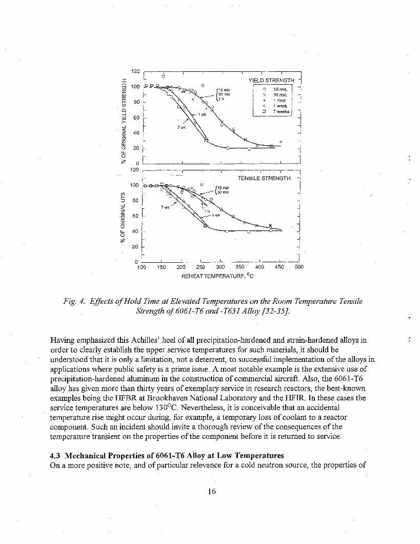
The.thermal instability displayed in Fig. 3 is for materials held and tested at the indicated temperatures. The softening contains a contribution from the temperature dependence of the elastic modulus, In cases where a component that usually operates at temperature below 130°C is inadvertently heated into the softening regime and then returned to its normal temperature, the degree of softening would not be as large as implied in Fig. 3. Nevertheless, it can be substantial, as shown in Fig. 4, derived from data in refs. 32-35, which gives the strength at room temperature after periods at the indicated reheat temperatures. Like in Fig., 3, the degree of softening during a
14

ww-Q o /,,I,~,JI~,III -300 -200 .100 0 100 200 300 400
TEST TEMPERATURE (“C)
Fig. 3. Effects of Test Temperature andHold Time at Test Temperature on the Tensile, Stress- Rupture, and Stress Relaxation Properties of 606l-Td and -T651 Alloy [25-311.
temperature excursion depends on exposure time, and more so on temperature. The strength of 6061-T6 alloy (and other tempered or strain-hardened aluminum alloys) will be impaired by accidental temperature transients above 200°C. Even a short, 15 mm. excursion to 250°C will cause noticeable softening; a trip to 425°C for 15 min. will totally erase the T6 temper, reducing the strength by 55% to a value close to the strength of annealed 6061, about 124 Mpa. The impairment will be permanent. Actually, the original properties can be substantially restored in a precipitation-hardened alloy by a till reheat treatment, at the risk of causing some distortion of the component. But reheat treating an irradiated component would be a difficult and dubious task because of the radioactivity and the involvement of transmutation products in the microstructural changes. The warning is clear. The T6 alloy should not be exposed to temperatures above its original tempering temperature of 160°C for long periods, a week or more, if the T6 strength is to be maintained.
15
60
120 ,-, i c ---T-----I--
c
-J------? TENSILE STRENGTH -j
t- 20 ’
1 0 1 I I / I I / / I
100 150 200 250 300 350 400 450 500
REHEAT TEMPERATURE, ‘C
Fig. 4. Effects of Hold Time at Elevated Temperatures on the Room Temperature Tensile Strength of 606l-T6 and -T65I Alloy [32-351.
Having emphasized this Achilles’ heel of all precipitation-hardened and strain-hardened alloys in order to clearly establish the upper service temperatures for such materials, it should be understood that it is only a limitation, not a deterrent, to successful implementation of the alloys in applications where public safety is a prime issue. A most notable example is the extensive use of precipitation-hardened aluminum in the construction of commercial aircraft. Also, the 606 l-T6 alloy has given more than thirty years of exemplary service in research reactors, the best-known examples being the HFBR at Brookhaven National Laboratory and the HFIR. In these cases the service temperatures are below 13O’C. Nevertheless, it is conceivable that an accidental temperature rise might occur during, for example, a temporary loss of coolant to a reactor component. Such an incident should invite a thorough review of the consequences of the temperature transient on the properties of the component before it is returned to service.
4.3 Mechanical Properties of 6061-T6 Alloy at Low Temperatures On a more positive note, and of particular relevance for a cold neutron source, the properties of
16
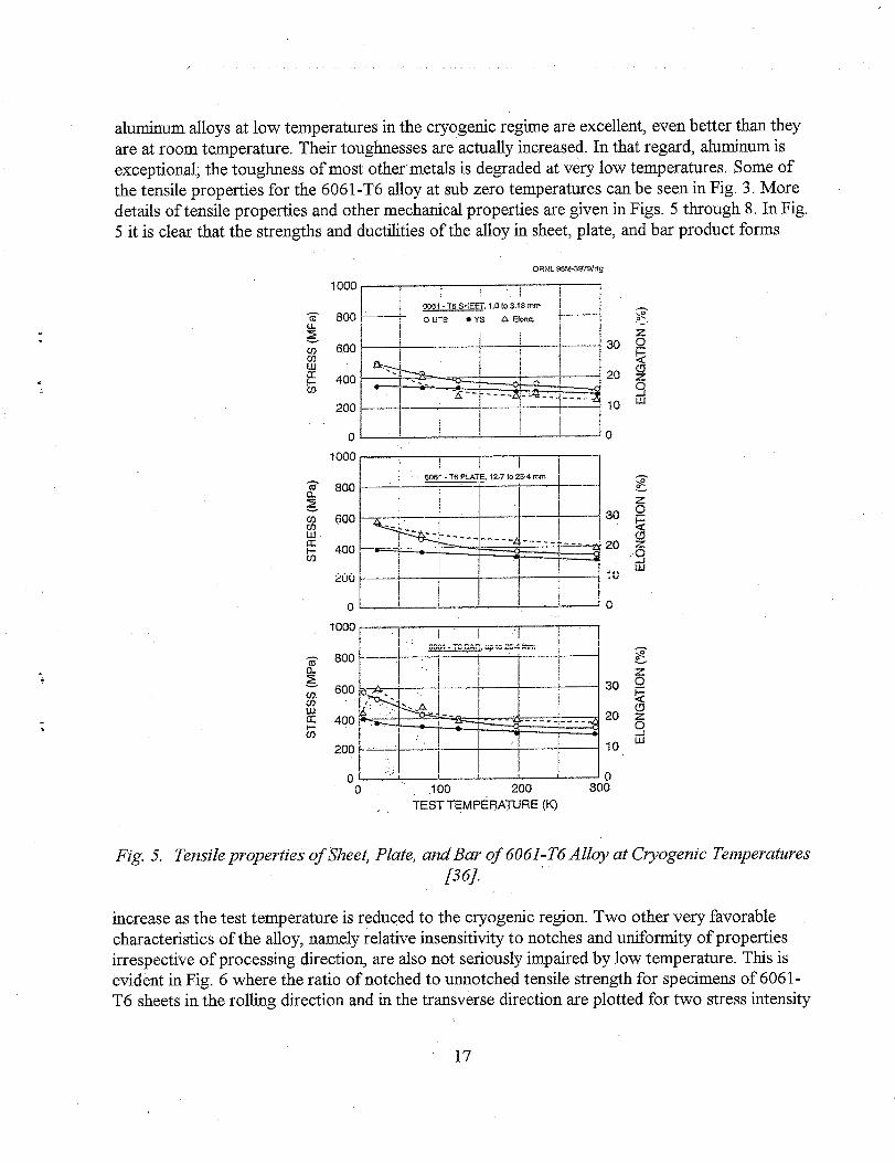
aluminum alloys at low temperatures in the cryogenic regime are excellent, even better than they are at room temperature. Their toughnesses are actually increased. In that regard, aluminum is exceptional; the toughness of most other metals is degraded at very low temperatures. Some of the tensile properties for the 6061-T6 alloy at sub zero temperatures can be seen in Fig. 3. More details of tensile properties and other mechanical properties are given in Figs. 5 through 8. In Fig. 5 it is clear that the strengths and ductilities of the alloy in sheet, plate, and bar product forms
ORNL 98MJ979/dg
1 I 606t-T6SHEET.1.0Lo3.18mm /
@Jo / 0 UTS . YS A EIo~Q.
800
01 :,,: I I I
" 0 200 3000 ,100
TEST TEMPiRATURE (K)
Fig. 5. Tensile properties of Sheet, Plate, and Bar of 606I-Td Alloy at Cryogenic Temperatures [36-J
increase as the test temperature is reduced to the cryogenic region. Two other very favorable characteristics of the alloy, namely relative insensitivity to notches and uniformity of properties irrespective of processing direction, are also not seriously impaired by low temperature. This is evident in Fig. 6 where the ratio of notched to unnotched tensile strength for specimens of 6061- T6 sheets in the rolling direction and in the transverse direction are plotted for two stress intensity
17

0 50 100 150 200 250 300
TEMPERATURE (K)
Fig. 6. Effects of Rolling Direction, Notches, Stress Intensify Factor, and Cryogenic Test Temperatures on the Tensile Strength of 606-l-T6 Alloy Sheet [3 71.
factors,. 3.5 and 2 1. Data for intermediate factors and for thinner sheet fall within these boundaries and also show little effects of rolling direction [37]. The reduction in strength ratio at 20K is about 25% for the sharpest notch. The implication is that the alloy has good resistance to tearing at low temperature, and this is confirmed by the tear resistance data for aluminum alloys displayed in Fig. 7. Good tear resistance is a highly desirable asset for thin-walled structures like the cold source vessel and the vacuum tube. Failure in a thin material is more likely to occur by tearing than by brittle crack propagation. In aluminum alloys, tear resistance is an inverse function of tensile strength. In terms of tear resistance, the 6061-T6 alloy is much superior to the stronger . 2XXX and 7XXX heat treated alloys and is considerably better than the strain-hardened 5xXx series alloys of similar strength. The fracture resistance of 6061-T6 alloy is not confined to sheet material. Plate and bar stock are tough, too. The Charpy impact properties of plate and bar, and the plane-strain fracture toughness parameter, Kr c, of plate are shown in Fig. 8. Both parameters are increased slightly at cryogenic temperatures. The critical stress intensity factor exceeds the ASME recommended reference stress intensity factor of 25.3 MPa drn.
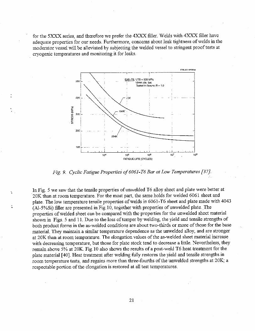
In accordance with the increased deformation resistance at low temperatures, the fatigue strength is also increased substantially, as shown in Fig. 9. Although fatigue is unlikely to be an issue for the HFIR cold source, it is reassuring to know that the fatigue properties of.606 1 -T6 alloy are consistent with the improvements in other mechanical properties of the alloy at low temperatures.
18

ORNL2001-0347fIwp
250. I I I I 1
0
TEMPERATURE (K)
Fig. 7. Tear Resistances of Sheet and Plate of Various Aluminum Alloys at Sub Zero Temperatures [38]. Tear Path is Transverse to the Rolling Direction.
4.4 Welds
.
To ensure that conservative design guidelines are applied and national quality assurance standards are met or exceeded, the cold source will be designed and constructed to ASME boiler and pressure vessel recommendations. Code Case N-5 19 [23] covers 606 1 -T6 alloy. It permits welds. Construction of the HFIR cold source will involve welds at two locations, a girth weld in the moderator vessel and circumferential welds in the hydrogen lines. Welding is the most severe form of overaging for a precipitation hardened alloy, and it will certainly reduce the strength of the 6061-T6 alloy in the immediate vicinity of the weld. The minimum room-temperature ultimate tensile strength of a weld in T6 and T65 1 material is specified by the ASME code as 165 MPa, which is 57% of the T6 strength. Under the code rules, the maximum service stress a weld could safely support is one-third of 165 h4Pa, i.e. 55 MPa. By coincidence, the maximum stress expected on the most highly stressed region of the moderator vessel wall is 55 MPa; but it is not at a weld. It is in the unwelded T6 material. So the girth weld in the vessel will have ample strength to satisfy the code recommendations.
The most serious questions the welds raise for the cold source is not whether they will have sufficient strength, but whether they can be made leak tight, and will remain leak tight during service. In essence, a fusion weld is really a cast material, and it bears some of the problems and uncertainties of castings, notably a tendency for porosity and shrinkage, and mechanical properties inferior to wrought products. Porosity is a problem with many welds and is particularly burdensome for thin wall aluminum because the high rates of thermal conductivity and thermal expansion of aluminum causes the weld pool to freeze and shrink rapidly with large volume
19

changes, introducing shrinkage cavities. This problem is overcome to a large extent by using weld
ORNL 20M-0346Wwp
I / / :
LONG. TRANS
CiiARPY K, t 9 mm bar
I I I I I I
0 50 100 $50 200 250 300
TEMPERATURE (K)
0RNL209103470hp
a
g 20 384
#
mm plate, WL orientation
*not meaningful because specimen
50 100 200 300
TEMPERATURE (K)
Fig. 8. Temperature Dependence of Charpy Impact [37] and Fracture Toughness [39] Properties for 606l-Td and -T6.51 Plate and Bar.
filler metals of relatively low melting temperature such as the 4XXX (Al-Si) series. These filler metals allow the molten weld pool to stay fluid for longer periods, enabling more flow into shrinkage cavities during cooling of the weld. If ductility of the weld is a concern, a 5xXx series filler metal gives welds with better ductility than the 4XXX fillers. However, for our case the use of a 5xXx filler would introduce worries about the deleterious radiation effects mentioned earlier
20
’ for the 5xXx series, and therefore we prefer the 4XEC filler. Welds with 4XXX filler have adequate properties for our needs. Furthermore, concerns about leak tightness of welds in the moderator vessel will be alleviated by subjecting the welded vessel to stringent proof tests at cryogenic temperatures and monitoring it for leaks.
6061-T6, UTS = 305 MPa 7 19mm dia. bar.
Tested in flexure; R = 1 .O
b II/I I II,; , /,: I I,! , 1 I,
104 105 106 10’ 108 ,
FATIGUE LIFE (CYCLES)
Fig. 9. Cyclic Fatigue Properties of 6061-T6 Bar at Low Temperatures [37]. i
In Fig. 5 we saw that the tensile properties of unwelded T6 alloy sheet and plate were better at ‘20K than at room temperature. For the most part, the same holds for welded 6061 sheet and plate. The low temperature tensile properties of welds in 606 l-T6 sheet and plate made with 4043 (Al-S%Si) filler are presented in Fig. 10, together with properties of unwelded plate. .The properties of welded sheet can be compared with the properties for the unwelded sheet material shown in Figs, 5 and 11. Due to the loss of temper by welding, the yield and tensile strengths of both product forms in the as-welded conditions are about two-thirds or more of those for the base material. They maintain a similar temperature dependence as the unwelded alloy, and are stronger at 20K than at room temperature. The elongation values of the as-welded sheet material increase with decreasing temperature, but those for plate stock tend to decrease a little. Nevertheless, they remain above 5% at 20K. Fig. 10 also shows the results of a post-weld T6 heat treatment for the plate material [40]. Heat treatment after welding fully restores the yield and tensile strengths in room temperature tests, and regains more than three-fourths of the unwelded strengths at 20K; a respectable portion of the elongation is restored at all test temperatures.
21

0 @X1-T6 plate, 12.7-25.4 &, unwelded
D 6061.TS slate. t2.7.25.4 mm. MIG welded, 4043 Al filler
then given a T6 hear fieatment
V 6OWT6 siyet. 1.0-3.1s mm. M!G welded. 4043Al filler
800 -
0 100 200 300
TEMPERAT’UR~ W
Fig. IO. Low Temperature Tensile Properties of 4043 Filler Welds in 604l-T6 Sheet and Plate. Drawnporn data in references 36 and 40.
In keeping with the reduction in strength by welding, the notch strength is reduced, too, but not drastically even at low temperature [41]. Fig. 11 shows the temperature dependence of the notched and unnotched tensile strengths of 3 mm thick sheet of 606 l-T6 alloy before and after welding. The sharp side notches had a stress concentration factor of 30.3. It can be seen that at room temperature the notch has little effect on the tensile strengths of the unwelded parent metal and the weld. At 2OK, the notch reduces the strength of the weld more than it does the parent metal, but the notch strength of the weld is still greater than at room temperature. These data indicate that 4043 tiller welds in the T6 alloy retain considerable toughness. This is borne out by fracture toughness tests [42] on 4043 filler welds in 606 1 -T65 1 plate which show KJ values of 46- 54 MPaJm at room temperature, better than the unwelded parent metal values of 32-34 MPaJm.
22

e
O- 1 I I I I I
0 50 100 150 200 250 300
TEMPEWTLJRE 09 ‘1 .
Fig. Il. Strengths of Notched and Unnotched 4043 Filler Welds and UmYelded Parent Metal of 3 mm Sheet 6061-T6 Al at Low Temperatures [41]. The notch stress concentration factor is 30.3.
ASME code case N-5 19 allows welds in 606 l-T6 alloy but it forbids post-weld heat-treatments. The reason for this ban is that tensile elongations as low as 2% at room temperature and 3% at 77K have been recorded for plate material welded with 4043 filler then given a T6 heat treatment, compared with 12% and 7.5% at respective temperatures for non-heat-treated welds [43 J. Such low ductilities after post-weld heat treatment are not the norm. Fig. 10 shows that heat treatment to the T6 condition after Gelding can actually improve the post-weld elongation of 6061-T6 alloy, elongations of 15% or more being obtained at all test temperatures. This increase in elongation presumably arises because raising the strength of the weld will reduce the potential for strain localization at the weld. These conflicting data indicate that there can be significant variation in the ductility of post-weld heat-treated 606 1 -T6 alloy. Part of the variation might have been caused by flaws in the welds. That being so, a rigorous program of detection and elimination of flaws in the welds will ensure acceptable ductility. Since all welds in the HFIR cold source will be subjected to stringent flaw elimination to ensure leak tightness, it follows that ductility should be optimized, too. Another potential cause of variation in weld ductility could be the amount of 4043 filler alloy in the weld. Too much filler might produce excessive precipitation of silicon and associated low ductility during heat treatment. In that regard, welds in the thin-wall cold source should require less filler than welds in plate, and should be less prone to low ductility after heat treatment.
,
This point about post-weld heat treatment is made to demonstrate that not all heat treated welds in 606 1 alloy will have poor ductility, and to show that with care low ductility welds can be avoided. Therefore, it is suggested that if the need arises to increase the strength and ductility of the welds in the HFIR cold source, the ban on post-weld heat treatment in the ASME code should be reconsidered. Further comments on the application of the ASME code follow.
23

5.0 Comments on Application of ASME Code Although the HFIR cold source moderator vessel could be exempted from strict ASME boiler and pressure vessel code requirements because it is not part of the primary containment boundary of the HFIR, and it is smaller than the minimum 6 in. diameter (150 mm) covered by the ASME code, it will be built to ASME code recommendations. Designing the vessel to ASME code recommendations will provide a conservative design guideline and a high level of quality assurance during fabrication. But adherence to the code affords no guarantee that deterioration of the source may occur and require it to be replaced at a shorter interval than planned. It must be recognized that the vessel will not meet the minimum fracture toughness criteria required for larger code-approved pressure vessels. In the first place, the vessel will be too small and the wall thicknesses too thin to give a satisfactory measure of fracture toughness as defined by the code. In the second place, the toughness of the HF$R cold source vessel, like all cold neutron source vessels, will be impaired by severe hardening and loss of ductility as a result of low temperature neutron irradiation. The code does not address such embrittlement. Even though substantial increase in strength will occur during cryogenic irradiation, the code allows no credit to be taken for it. Moreover, the code says nothing about the expected large loss of ductility, which may be the major hurdle faced by the vessel in service. But the designer is expected to take cognisance of the ductility loss and make appropriate allowances for it. The allowances are not defined by the code. They are left to the discretion of the designer. These uncertainties apply to all cold neutron sources. Despite them, there have been no dangerous failures of existing cold neutron sources.
6.0 Radiation Effects in Aluminum Alloys Irradiation of the cold source components will considerably alter their physical and mechanical properties. The principal effects will be increases in strength and associated losses in ductility, and some swelling. The nature and extent of the changes will depend strongly on the neutron fluence and more strongly on the irradiation temperature. A cold source has two quite distinct temperature zones, a very low temperature in the moderator vessel, in our case 2OK, and a much higher temperature in the vacuum tube and its immediate surroundings, in our case 3 1%398K (45- 125°C). For aluminum these represent homologous temperatures of O.O2T, and up to 0.43T, respectively, which will cause enormous differences in the nature and consequences of the radiation damage. Before proceeding to discuss the specific effects of irradiation expected in individual components of the cold source, it is instructive to review the general effects of neutron irradiation in metals, and the effects on aluminum and the 606 1 -T6 alloy in particular.
6.1 Point Defects and Transmutation Products Neutron radiation effects in metals in general are due primarily to radiation-produced point defects and transmutation products, created in the metal atom lattice. Point defects are generated when an incident neutron knocks an atom from its lattice site via an elastic or inelastic collision. An inelastic collision involves absorption of the neutron by the atom and subsequent emission of a particle (7, a, or p) whose release causes the nucleus to recoil; this is more common with slow neutrons. In an elastic collision a fast neutron bounces off the atom like a billiard ball and imparts a portion of its kinetic energy to the atom. In both of these events, the recoiled atom is forced into an interstitial lattice position, known as a self-interstitial atom (SIA), and its emptied lattice site is
24

2
* 1
called a vacancy. The SIAs and the vacancies are’the point defects. The kinetic energy required to recoil an aluminum atom from its site is about 25 eV. If the kinetic energy transferred by the neutron or the decay recoil event is more than twice the displacement energy, the displaced atom carries sufficient energy to dislodge an adjacent atom as a secondary recoil, and so on in a cascade of displacements until successive secondary knock-on atoms no longer have enough kinetic energy to eject another atom, The number of displaced atoms in a cascade is roughly proportional to the energy transferred to the primary knock-on atom divided by twice the displacement energy. A 1 MeV neutron can transfer about 1.4 x lo5 eV to an aluminum atom, so the resulting cascade might involve several thousand atoms. Hence, in most reactor neutron spectra most of the point defects will be created by fast neutrons and the degree of radiation damage will scale with fast neutron fluence, usually expressed as the fluence greater than 0.1 MeV or greater than 1 MeV. An alternative, and now preferred, correlation parameter is the number of displacements per atom
@Pa).
Another source of atomic displacements is gamma rays. Gamma rays do not displace atoms directly. They energize electrons by Compton scattering or pair production; these electrons dislodge the atoms. Such displacement events produce Frenkel pairs of SIAs and vacancies, not cascades, and the displacement cross section is much smaller, than for-neutron displacements. Gamma rays with energies >l MeV will produce Compton electrons with maximum energies about 0.8 MeV. In aluminum, the displacement cross section for 0.8 &IeV electrons is 25 b [44]. The displacement cross section for neutrons with energies >l MeV is more than 1100 b [45]. In the irradiation environment at the HFIR cold source the gamma flux will be about twice as large as the fast neutron flux and, therefore, the contribution of gamma displacements will be less than 5% of those from fast neutrons,
. 4
In the HFIR cold source, as in other cold sources, most of the displacement damage will originate from the background of higher energy neutrons impinging on the vessel.
f The quantities of transmutation products in construction alloys are usually small and relatively innocuous with respect to their effects on mechanical properties at room temperature and moderately higher temperatures. The two most common ones are the gases hydrogen and helium generated from (nip) and (n,&) reactions by fast neutrons. The production cross sections for these reactions in aluminum in various reactor neutron spectra are small, approximately 3 mb and 0.5 mb, respectively, for neutrons with energies > 0.1 MeV [45]. From these cross sections and a peak fast neutron flux of 5.7 x 1 017 n.m-‘. s-l, E > 0.1 MeV expected at the IIFIR cold source vessel at 100 MW power level [ 181, the production rates of hydrogen and helium are estimated to be about 5 and 1 appm per effective full power year (EFPY). These quantities are not considered worrisome. With regard to solid transmutation products, in most metals the amounts of solid transmutants are usually of order a few atomic parts per million per year, and their effects on mechanical properties are nil or minor. Aluminum is an exception. Its major transmutation product is silicon which has major effects on the mechanical properties of the aluminum. Silicon is produced by the sequential reaction A127(n,y)A128 -+Si2’ + p-. The production cross section is large, 230 mb for neutrons with energy 0.025 eV (2200 m.s-I), and larger at lower energies. It is
I 25

estimated that about 0.7% Si will be generated per EFPY in the cold source vessel [ 181. This silicon will significantly affect mechanical properties, as explained below.
6.2 Radiation Hardening The radiation effect of most interest to this report is radiation hardening and associated loss of
ductility. In general, radiation hardening is caused by clusters of vacancies and clusters of SIAs that obstruct the passage of glide dislocations during plastic deformation of the metal. The more clusters the greater the degree of hardening. Hardening is very sensitive to irradiation temperature because the temperature is a major arbiter of the number and size of the clusters. The lower the temperature the smaller the .clusters and the greater their number. It is a well-established fact that radiation hardening produced at cryogenic temperatures is very much greater than radiation hardening at room temperature which, in turn, is greater than that at more elevated temperatures.
The clusters are formed by two major processes. One is by in-cascade condensation of point defects during the rapid cooling period immediately succeeding the creation of the hot, defect-rich displacement cascade. In this condensation process, many SIAs return to vacated lattice sites, annihilating an equal number of vacancies, some point defects are expelled from the cascade region, and many of the remaining like point defects agglomerate into clusters. Immediately following the condensation phase the surviving vacancies tend to be near the core of the cascade, and the SIAs are at the periphery of the cascade volume. Irradiation temperatures of interest to the present work, below 0.3T, have only minor effects on this condensation process.
The other mechanism of cluster formation occurs in the bulk lattice .by migration and aggregation of freely-migrating point defects (fmpds) that avoided in-cascade recombination and clustering. During this process most of the finpds become absorbed at nearby sinks such as the clusters, which grow or shrink depending on whether the incoming fmpd is a like or unlike defect. Other fmpds are taken up at relatively widely-separated sinks such as dislocations, grain boundaries, and precipitate particles, or are annihilated by meeting with an unlike fmpd. The small remainder. forms new clusters. This migration phase is very strongly affected by irradiation temperature.
In aluminum irradiated with neutrons whose spectra contain low energy neutrons, the transmutation-produced silicon constitutes another source of radiation hardening. Silicon is almost insoluble in aluminum at temperatures below about 200” C. In unalloyed aluminum, transmutation-produced silicon forms a precipitate phase of elemental silicon [14]. If free magnesium is available in solid solution, as in the 5000 series aluminum alloys, the silicon will react with the magnesium during irradiation to form Mg,Si precipitate [ 10-121. In aged 6000 series alloys, which already contain thermally-induced Mg,Si phase, there is no free magnesium and the transmutation-produced silicon forms particles of elemental silicon which coexist with the Mg,Si precipitate [ 15,161. These precipitates harden the alloy. In any precipitation hardening system the degree of hardening caused by the precipitate phase is dependent on the volume fraction of the phase and on the size of the precipitate particles; the finer the precipitate the greater the hardening. Formation and growth of the precipitate particles requires migration and coalescence of the constituent atoms of the phase which are transported by a vacancy exchange
26

process. More vacancies are made available by increased temperature and by the point defects generated by atomic displacements. A harder neutron spectrum, which will give more vacancies than a soft neutron spectrum, will also induce coarser precipitates and less hardening per unit amount of precipitate phase. Hence, it can be expected from the irradiation standpoint that there might be an effect of irradiation spectrum. There is evidence that this deduction is valid for precipitate particles of transmutation-produced silicon in aluminum where it is seen that increases in strength tend to be larger with increasing ratio of thermal flux to fast flux [ 171, i.e. with a softer neutron spectrum. Because neutron irradiation hardening in aluminum at room temperature and higher temperatures entails both silicon production and considerable self-annealing of point defects, the degree of hardening often scales better with thermal neutron fluence (i.e. with transmutation-produced silicon) than with fast neutron fluence [ 16,191.
6.2.1 Radiation Effects at Cryogenic Temperatures Radiation damage produced at cryogenic temperatures is very much more severe per unit displaced atom than at higher temperatures. That is, there are many more point defect clusters and more hardening. Increased concentrations of clusters at low temperature stems from a combination of two temperature-sensitive factors. One is the increased stability, or survival rate, of clusters. Cluster stability is governed by thermal evaporation of point defects from the clusters and the arrival of fmpds at the clusters. Low temperatures reduce evaporation rates and slow the ingress of fmpds. The other factor is an increase in the nucleation rate of point defect clusters . formed by bulk diffusion and agglomeration processes. This factor is dependent on the availability and transport of fmpds. The availability, or supersaturation, of fmpds is very much greater at lower temperatures. Although migration of fmpds decreases with decreasing temperature, there is still sufficient mobility, particularly for SIAs, to ensure copious nucleation of clusters.
With regard to mobilities of f’inpds, the migration energies of an SIA and a vacancy are very different. In aluminum, the SIA has a migration energy of - 0.1 eV and the vacancy has a migration energy of about 0.65 eV [46]. Thus, SIAs can move at much lower temperatures than vacancies, or can move a lot farther at a given temperature. At a temperature of 20K, SIAs and vacancies are frozen. The clusters produced in a cold source vessel during irradiation at 20K will be predominantly those created at the cascades; there will be no bulk migration of point defects to I influence them and to create new clusters, and no thermal evaporation from them. Vacancies attain significant mobility at an homologous temperature above about 0.3 T,,,, i.e. near room temperature for aluminum. At lower temperatures between 20K and room temperature, the SIAs are the more mobile and they can recombine with isolated vacancies and vacancy clusters, reducing the population of vacancy clusters, and they can enhance the development of SIA clusters. Within this temperature range an increasing temperature weakens the thermal stability of clusters and many are lost by evaporation and shrinkage. Consequently, a great deal of so-called self annealing of radiation damage occurs in aluminum at temperatures between 20K and room temperature. Correspondingly,’ radiation hardening is reduced.
For aluminum, a typical room temperature of 25°C represents a homologous temperature of 0.32T,, where thermally-driven processes are active. Consequently, irradiations made on
27

aluminum at room temperature, or post-irradiation “anneals” performed at room temperature after irradiation at cryogenic temperatures, will allow substantial thermal recovery of the irradiation damage and will therefore leave relatively coarse displacement damage microstructures which contribute little to radiation hardening. This recovery is well documented, e.g. refs.[47,48], and further examples are illustrated in Figs, 12 and 13, compiled from refs. [49-5 11. Before digesting these two Figs. be aware that the pronounced irradiation effects described in them are due to clusters of point defects, not to silicon. For the 77K and 27K data the clusters were developed during irradiations made in liquid nitrogen and liquid neon with fission spectrum neutrons. Little or no transmutation-produced silicon was involved. The 300K irradiations were made in the HFIR core. At 300K, displacement damage is considerably self-annealed in aluminum. The small measured increase in strength at 300K is due primarily to silicon produced by the large fraction of thermal neutrons in the IIFIR core neutron spectrum.
In Fig. 12, the tensile test curves for annealed aluminum irradiated and tested at three different temperatures are compared. Unfortunately, because of a paucity of data for cryogenic irradiations for a given material, it is necessary to represent each of the three temperatures in Fig. 12 with different materials, ranging from 99% purity (1100 Al) at room temperature through 99.5% (A5 Al) at 77K to 99.99+% (super pure Al) at 27K. Since it is known that radiation strengthening diminishes with decreasing purity due to promotion of recombination of point defects by impurity atoms, this exaggerates the increases in strength with decreasing irradiation temperature in Fig. 12. The exaggeration is absent in Fig. 13 for the 77K and 27K plots where it is quite clear that radiation strengthening of originally cold worked A5 aluminum is much greater at 27K than at 77K for otherwise identical conditions. This difference must be a result of greater retention of displacement damage at the lower irradiation temperature. Note, too, that this increased strengthening occurs despite the presence of cold work dislocations which should absorb many SIAs and thereby diminish the degree of radiation strengthening. The continuous increase in radiation strengthening with decrease in temperature seen in Figs. 12 and 13 implies that radiation hardening may be even larger at 20K than at the low of 27K in the Figs.
The most disconcerting feature of Figs. 12 and 13 is the very considerable loss in elongation, especially at the lower temperatures. Even the normally very ductile super pure aluminum displays only a few percent elongation after a mild irradiation of 1 x 1O23 n.mb2 at 27K. The descriptive “mild” is used here in the sense that the dose of 1 x 1O23 n.mm2, E> 1MeV in Figs. 12 and 13, is equivalent to only five to six days exposure in the IIFIR cold source. A more reassuring feature of Figs. 12 and 13 is that much of the strengthening and loss in ductility induced by irradiation at cryogenic temperatures can be restored by returning the irradiated material to room temperature. Restoration is complete for a 60 h room temperature anneal in the cold worked A5 alloy, Fig. 13, but some ductility loss remains for the originally annealed A5 alloy, Fig. 12. Regrettably, the details of the restoration treatment for the formerly annealed alloy are not available. Presumably, it was similar to the room temperature anneal for the cold worked alloy. The more complete recovery of properties in the cold worked alloy is taken to be due to the high density of cold work dislocations which will provide more sinks for mopping up mobile point defects.
28

1100 Al, 300K (0.32-F,,,)
0 10 20 30 40
ELONGATION,%
A5 Al, 77K (O.O8T,) Superpure AI, 27K (0.031,)
1 x 10z3n.mQ, Eh 1 MeV,@77K
400
3.8 x 1O22 n.mA2, E> 1 MeV,027K
300
ELONGATION, % ELONGATION, %
Fig. 12. Tensile Test Curves for Three Grades of Annealed, Unalloyed Aluminum Before and After Irradiation and Tesbg at Room Temperature and Cryogenic Temperatures f49-511.
i’
:
Nothing is known about the nature and effects of transmutation-produced silicon created in an aluminum cold source vessel during irradiation at cryogenic temperatures. Some reasonable speculations can be made. First, the silicon atoms generated at 20K in the HFIR cold source will not form precipitate particles in the vessel wall during the irradiation. The silicon will be retained in atomic form; some will likely become complexed with point defects clusters created in the displacement cascades. The silicon atoms will supplement the low temperature radiation hardening but their contribution will likely be small compared to the gross hardening from the point defect clusters. Second, unlike the point defects, the silicon atoms will not anneq.out when the cold source is periodically allowed to warm up to room temperature. Rather, the &con will continue to accrue with irradiation exposure. It is estimated [ 181 that the maximum generation rate for silicon at the “h0ttest”par-t of the tip of the moderator vessel facing the reactor core will be approximately 0.7% Si per full power year (365 days at 100 MW). For a duty factor of 80%, the silicon production rate will be 0.56% per year. Third, during periodic room temperature anneals the silicon will probably form fine precipitates. As the temperature is raised from 20K and vacancies become mobile, they will assist the diffusion of silicon atoms. Transport distances will be short before the vacancies are annihilated, and the ensuing nucleation rate of silicon
29

precipitates will be high. This process will, in essence, be an accelerated natural aging process. The switch from solute hardening to precipitation hardening will exacerbate the hardening from the transmutation-produced silicon. The degree of hardening from this process is expected to be greater than that produced by the same amount of silicon during a normal thermal aging treatment or generated during a room temperature irradiation because more nucleation and less coarsening of the silicon precipitates will occur via the cryogenic irradiation-room temperature anneal route. In 5000 series alloys, this route can be expected to produce very fine Mg,Si precipitates.
1100 Al, ZO%CW
I e (0.32Tm)
ELONGATION,%
A5 Al, - 35% CW m (O.OST,)
: f : 01’ ,’ / I
0 IO 20 30 40
ELONGATION, %
t t A5 Al, - A5 Al, - 35% CW 35% cw
500 - 500 - 27K (O.O3T,) 27K - - (O.O3T,)
-i~lU~n.m‘~,E>l f&V -i~lu~n.m‘~,E>l f&V
400 - 400 -
0 10 20 30
ELONGATION. %
Fig. 13. Tensile Test Curves for Two Grades of Cold Worked, Unalloyed Aluminum Before and After Irradiation and Testing at Room Temperature and Cryogenic Temperatures [49-5IJ.
6.3 Tensile Properties of Neutron Irradiated 6061-T6 Aluminum Most aluminum components in reactors operate at temperatures in the range 40-200°C (0.33- 0.5 lTJ, where the higher temperatures in the range are usually for me1 cladding. Therefore, neutron irradiation hardening of such components by point defect clusters is weak. For irradiation temperatures of about 60-125”C, pertinent to those expected for the HB-4 beam tube and the cold
L c
30

source vacuum tube, there is a significant body of mechanical properties data for the 606 1 -T6 alloy after substantial levels of neutron irradiation in contact with reactor coolant water in light ., I _. _.. -i. .- ,., “_. 1. ;e ;i . / I / jl.” i*L; ‘Zi‘” :~~x \II ;. :, water and heavy water reactors. The tensile properties of the irradiated alloy in the T6 and T6S 1 conditions are shown as functions of thermal neutron fluence in Fig. 14, taken from ref. 24. The curves drawn through the data represent the observed upper boundaries for the ultimate tensile strength and the yield strength, and the lower boundaries for total and uniform elongations. The data points encompass results from irradiations in hard, and softened neutron spectra, which accounts for some of the
800 f
A I v I / I I I I I I I
A ULTIMATESTRENQTH o YIEUI STRENGTH P i
700 i c /”
I u” I I I I I I I I A TOTAL U UNIFORM
AA A
a
THERMAL FLUENCE (urn’)
Fig. 14. Tensile Properties of 606I-T6 and 606I-T65I Aluminum Alloy After Neutron Irradiation at Temperatures dO”C< TIRR< I OO’C [24].
scatter in the data. Notable changes in strength and ductility do not occur until a thermal neutron fluence of about 1 x 10z5 n.m-’ is exceeded. At that fluence about 0.023% of transmutation- produced silicon is created which is responsible for the onset of strengthening. The associated fast fluence (EP 1MeV) is about 2 x 1 024 n.mS2. This level of fast fluence would cause considerable
31

hardening by atomic displacements in most higher melting point metals during irradiation at 65”C, but it has little effects in aluminum because the homologous temperature is high enough for substantial concurrent annealing of point defects.
It has been reported that 6061-T6 type alloys can undergo softening during irradiation [52,53]. These reports conflict with extensive experience at ORNL and Brookhaven National Laboratory (BNL). Intensive investigations of the claims were conducted at ORNL by the present author, and no confirmation of them was found. It was deduced that the softening observed by the claimants may have resulted from inadvertent radiation heating of the specimens, which were irradiated in sealed cans. These conclusions were conveyed to the claimants and were later made public [54]. Subsequent experiments by the claimants under closer temperature control [55-571 did not reproduce the softening except when the irradiation temperature exceeded 200°C [55]. These conflicts emphasize the necessity of careful temperature control during irradiations of thermally unstable materials.
The sparse information on effects of neutron irradiation at cryogenic temperatures on the tensile properties of 6061-T651 alloy [58] is shownin Fig.15. Tensile specimens cut from 6061-T651 plate were irradiated in liquid nitrogen at 77K to several fast neutron doses (E>l MeV) up to about 1 ~10~~ n.mT2, and were tested at temperatures between 77K and room temperature. For tests made at 77K these modest fluences caused pronounced radiation-induced increases in yield strength and tensile strength, and large reductions in elongation values; the uniform elongation was reduced to about 1%. When the tests were conducted at room temperature there was complete recovery of properties to the m&-radiated values.
6.4 Fracture Toughness The same experiments that produced the low temperature tensile properties for irradiated 6061- T65 1 alloy described above and shown in Fig. 15 also measured fracture toughness data, as seen in Fig, 16. Despite the significant effects of irradiation and cryogenic temperature on the tensile properties, there were little or no effects on fracture toughness.
The fracture toughness data available for 606 l-T6 and -T65 1 alloys irradiated at temperatures between 60°C and 100°C [ 16, 421 are summarized in Fig. 17. The superscript numerals on the data points indicate the ratio of thermal neutron flux to fast neutron flux (E>O. 1 MeV), and are a measure of the softness of the neutron spectrum. After irradiation to thermal fluences of 1 ~10~~ n.m2 and 8 ~10~~ n.m2 in a fairly hard spectrum (thermal-to-fast flux ratio 2) the fracture toughness is not greatly altered. Irradiation to a thermal fluence of 4 x10” n.m2 in a much softer spectrum (ratio 20) reduces the toughness to about 25% of the u&radiated toughness [ 161. Corresponding tensile tests for this highly irradiated material show retention of about 6% elongation [ 161.
. *
32

5 w 0 50 700 150 200 250 300
TESTTEMPERATURE (K)
Fig. 15. Temperature Dependence of Tensile Properties of 6061-T6.5I Plate After Irradiation at 77K [58].
606l-T651 Tia = 77K
0 c -.2
ki
-4
L / I
1 01 s I / I I I
0 50 100 150 200 250 300
TEST TEMPERATURE (K)
Fig. 16. Temperature Dependence of Fracture Toughness of 606I-T65I Plate After Irradiation at 77K [58].
33

01 I 1 I I I
0 IO 20 30 40 50
. h
THERMAL FLUENCE (x1026n.m”)
Fig. 17. Fracture Toughness of 606I-Td and 6061-T65I After Neutron Irradiation at Temperatures 60”C~T,,~I00”C [16,42]. The superscripts are the ratios of thermal-to- fast
neutron flux. The subscript w denotes welds.
6.5 Swelling Swelling is an increase in volume of an irradiated material caused by accumulation and agglomeration of point defects and foreign atoms. It involves diffusion of atoms and vacancies and, therefore, usually requires homologous irradiation temperatures greater than 0.3 T,. One form of swelling is the formation of gas bubbles which arises from the accumulation of the transmutation-produced gases hydrogen and helium with vacancies. Another, is void swelling which results from the partitioning of vacancies and SIAs. Bubble swelling is more favored at temperatures > 0.5T, and is less common than void swelling. In aluminum, there is a third type of
’ swelling due to precipitates of transmutation-produced silicon. The density of crystalline silicon is less than that for aluminum, 2.34 g.cm3 versus 2.70 g.cm3, and a given mass of silicon occupies more volume than the same mass of aluminum. Swelling data measured on various aluminum alloys irradiated at 55°C are presented in Fig. 18. These data are obtained from density measurements and they represent the combined effects of all forms of irradiation-induced swelling. The dashed line depicts the calculated swelling from precipitates of silicon only. The calculations assume the silicon to be crystalline. Examinations of the precipitates has shown them to be amorphous [ 151, which makes the line a little dubious. Compared to pure aluminum which swells readily, the 6061-T6 alloy has good resistance to void swelling at fast fluences up to 1 ~10~~ n.m2, E>l MeV. At lower fluences, voids are rarely found in the alloy, so the measured swelling below a fluence of 1 x10” n.m2, E>l MeV must be due to the silicon.
L
34
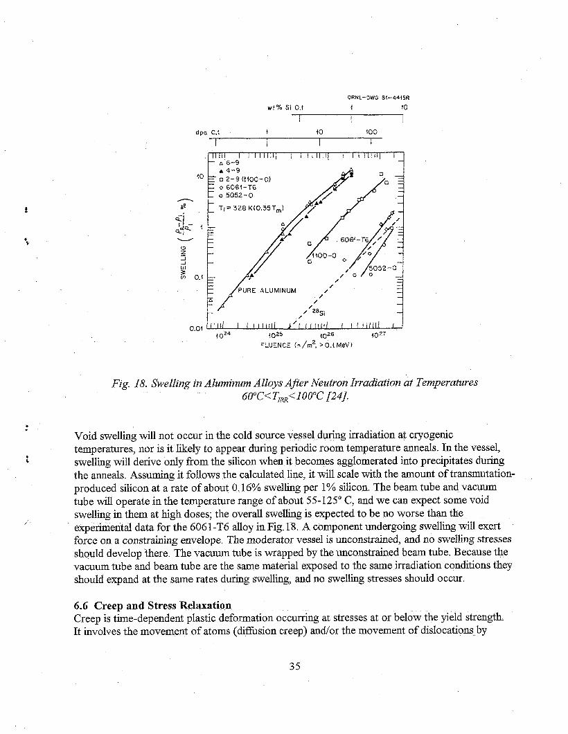
dpa 0.1
I
ORNL-DWG 81-44i5R
wt% Si 0.i
-l--h-+*
4 40 100
I
t
Puw ALUMINUM F/ /
, /
n /
/ /‘2aSi
0.01 “‘d ’ [ ’ “‘1” /- 1 ’ ’ tfl’f’ I ’ ’ t”l’l ’
4024 io25 4026 4027
FLUENCE h /rn’, > 0.4 MeVI
Fig. 18. Swelling in Aluminum Alloys After Neutron Irradiation at Temperatures .I 6OYX cm< IOo”C [24].
f
:
/’
Void swelling will not occur in the cold source vessel during irradiation at cryogenic temperatures, nor is it likely to appear during periodic room temperature anneals. In the vessel, swelling will derive only from the silicon when it becomes agglomerated into precipitates during the anneals. Assuming it follows the calculated line, it will scale with the amount of transmutation- produced silicon at a rate of about 0.16% swelling per 1% silicon. The beam tube and vacuum tube will operate in the temperature range of about 55-125” C, and we can expect some void swelling in them at high doses; the overall swelling is expected to be no worse than the experimental data for the 6061-T6 alloy in Fig. 18. A component undergoing swelling will exert force on a constraining envelope. The moderator vessel is unconstrained, and no swelling stresses should develop there. The vacuum tube is wrapped by the unconstrained beam tube. Because the vacuum tube and beam tube are the same material exposed to the same irradiation conditions they should expand at the same rates during swelling, and no swelling stresses should occur.
6.6 Creep and Stress Relaxation Creep is time-dependent plastic deformation occurring at stresses at or below the yield strength. It involves the movement of atoms (diffision creep) and/or the movement of dislocations by
35

absorbing or emitting atoms or vacancies (dislocation creep). Creep can distort a component and render it unfit for service. Continuous creep requires continuous application of stress. Stress relaxation is the easing of stress by the process of creep. Stress relaxation occurs when the stress can not be continuously maintained, such as in a one-time tightened bolt. These creep processes are thermally activated and they prevail at homologous temperatures above 0.3 T,, which means they can occur at room temperature in aluminum, albeit at high stresses in the vicinity of the yield stress.
Under irradiation, creep can be accelerated because the instantaneous excesses of point defects created by the neutron fluxes increase the involvement of atoms and vacancies, causing significant creep at lower stresses and reducing the temperature for the onset of creep. The rates of radiation-accelerated creep are largest in the point defect transient regime at the beginning of irradiation where the point defect concentrations are building up prior to reaching a steady state equilibrium condition.
Because radiation creep is driven by the excesses of point defects over the thermal equilibrium values, it tends to increase with decreasing temperature, contrary to thermal creep, but only at temperatures sufficient to ensure point defect mobility. In austenitic stainless steels, for which there is a great deal of data, irradiation creep prevails at homologous temperatures between 0.17 and about 0.55 T, and normalized stresses (ratio of applied stress to the yield stress) between 0.05 and 0.7. We would expect aluminum to display irradiation creep within similar temperature and stress boundaries as the stainless steel. But the data on irradiation creep in aluminum are sparse and conflicting. One experiment [59] conducted on pure aluminum in reactor at fluxes of 1.3 x 10¹⁶ n.m-2.s-1 pl MeV) and 6.0 x 10¹⁶ n.m‘2.s-1 (E<leV) at 55°C (0’.35 TJ and a normalized stress of almost 0.8 for 990 h showed no irradiation enhancement of creep. Another in-reactor experiment [60] on pure aluminum loaded to a normalized stress of 0.5 and irradiated with neutron fluxes of 2.5 x 10¹⁵ n.m-2.s-’ (E>O. 1 MeV) and 1.4 x 10¹⁶ n.mm2.sm1 (total) for periods of 100-400 h at homologous temperatures in the range 0.36 to 0.5 1 displayed substantial irradiation creep with enhancement factors (ratio of irradiation creep rate to thermal creep rate) in the range 10 to 20. In contrast, experiments performed by the writer on tubular specimens of 6061-T65 1 alloy internally pressurized to normalized hoop stresses of 0.2 to 0.4 and irradiated in the HFlR core at about 60°C (0.36 TJ in fluxes of 4.1 x 10¹⁸ n.ms2.sm1 (E>l MeV) and 2:2 x 101’ n.mb2.s-’ (thermal) for periods up to 85 days showed no signs of irradiation creep, nor thermal creep [6 l]. This lack of creep in the 6061-T6 alloy is puzzling. Experiments are underway to extend the tests to higher stresses. As things now stand, the evidence for irradiation-enhanced creep in aluminum is confusing and inconclusive.
Creep tests made after irradiation, when the production of excess point defects has been turned off, should not show radiation enhanced creep, at least for irradiations made at temperatures where the point defects are mobile. Such post-irradiation creep should be more difficult because residual radiation hardening will raise the stresses required for thermal creep and will reduce the creep rates. That has been demonstrated [62] for 1100 and 6061 aluminum alloys irradiated to fast fluences of 0.5 to 7.3 x 1O26 n.ms2 (E>O.l MeV) and thermal fluences of 0.7 to 1.1 x 1027n.m-2
*
II
n
36

t
;
(EcO.4 eV) at temperatures of 50 to 150°C in the Hj?IR core, then tested at 50 to 150°C ex- reactor. Stresses were chosen to induce failure in test periods of less then 1,000 h and, consequently, were high, more than 90% of the yield strength. For 606 1 -T6 alloy, irradiation caused about 35% increase in the stress for failure in a given time for specimens irradiated and tested at 5O”C, and a 10% to 20% increase.for specimens irradiated and tested at 150°C. Rupture ductilities were lowest at 15O”C, about 1% at 1,OOOh versus about 8% for the umrradiated material, and were coupled with a tendency for intergranular failure.
6.7 Radiation Effects in 6061 Alloy Welds The welded region in a 6061-T6 alloy is similar in microstructure to annealed 6061, with the addition of a little silicon or magnesium from the weld.filler alloy. Studies of annealed 6061 alloy [20] and of welds in 6061-T6 alloy [42] neutron irradiated at 60-90°C have revealed no deleterious discriminatory effects of irradiation on the annealed or welded material; the changes in tensile properties and fracture toughness after irradiation are comparable to those in 6061-T6 material. Studies of the effects of irradiation at cryogenic temperatures on welds are meager [63, 641. They involved longitudinal and transverse welds made in sheet [63] and in 0.25 in.(6 mm) plate [64] with 4043 Al filler then given a full T6 heat treatment prior to irradiation. Before irradiation, tensile yield strengths and ultimate strengths of the heat-treated welds were similar to unwelded T6 alloy; elongations were 6-9%. Specimens were irradiated to a fast neutron dose of 5 x 10²’ n.m-’ , PlMeV, at 2OK, and tested at 20K [63], or were irradiated to a similar dose at 77K and 20K [64] and tested at the irradiation temperatures. The as-irradiated yield and ultimate strengths were marginally increased; the elongations were raised to 10-l 1%. Fracture toughness data for welds after modest irradiation exposure are displayed in Fig. 17, where the w subscripts denote weldments made by the tungsten inert gas (TIG) process with 4043 Al filler metal. The unirradiated welded specimens in Fig. 17 have higher fracture toughness values than the parent T6 metal because of softening during welding. After irradiation, the toughness of the welds is the same as the toughness of the irradiated, unwelded parent metal.
These are encouraging results, and taken together with the findings reported in Section 4.4 showing that properties of welds in unirradiated 6061-T6 alloy are no more adversely affected by cryogenic temperatures than the properties of the parent metal, they might be read as an indication that radiation effects in welds at cryogenic temperatures are likely to be no worse than radiation effects in the parent material. However, in view of the variable quality of welds and the low levels of neutron exposure in [63] and [64], such a deduction would probably be optimistic. A more conservative conclusion would be that a weld in a 6061-T6-moderator vessel (or a weld in a cryogenic moderator vessel of ClyEy material) must be regarded as potentially the weakest link in the system.
7.0 Recommendations Regarding Material Quality, Procurement, and Component Fabrication To simplify purchasing, certification,, quality assurance, archiving and documentation, it is recommended that all the in-reactor components of the cold source be made from the same heat or billet of 606 1 -T6 alloy. Any high quality, documented heat from a reputable manufacturer
37

might be suitable. But, as outlined below, a specialty product might be better.
Cylindrical billets used for producing tubular hollow ware are fabricated from cast ingots by forging, extruding, or rolling. All cast ingots contain inclusions and segregated impurities which become extended into discontinuous stringers lying in the long axis of the billets during fabrication of the billets. In poor quality materials such stringers can be lines of weakness in the material and potentialcorrosion sites. Normally, the domed HFIR beam tubes are machined from solid cylindrical billets in the fully heat treated condition. Stringers located in the tips of the hemispherical sections of the tubes will run perpendicularly through the wall thickness. Since the stringers are discontinuous and the wall is relatively thick it is unlikely the stringers will create continuous paths through the wall: But some components of the cold neutron source will have walls that are only a few millimeters thick, and in these cases the presence of stringers may cause heightened concern. To minimize the presence of stringers and to reduce the possibility they will traverse the wall, one or both of two options should be considered. One option is to invest in a custom-made heat with low inclusion levels. The other option is to use blocks of 606 1 Al shaped by forging in multiple directions to break up the stringers, or cupped billets in which the directionality of the stringers is made to follow the contours of the cup. Cupping processes may require custom tooling which could be prohibitively expensive for making just a few components.
8.0 Anticipated Component Performance In this Section we consider the expected impact of the cold source operating conditions on the likely performance of the 6061-T6 components of the source, and of conditions and mitigating measures that should prolong the useful lifetime of the source. We begin by describing what we have learned from the existing HB-4 beam tube.
/
8.1 The Current HB-4 Beam Tube The HB-4 beam tube is located within the large beryllium reflector surrounding the reactor core. The existing HB-4 beam tube, which will be replaced by the new, integrated beam tube-cold source assembly, is approximately 102 mm internal diameter with a 9.5 mm thick’wall and a hemispherical end. The domed end of the tube terminates in the beryllium reflector surrounding the reactor core. The other, open, end of the tube passes through a flanged nozzle in the reactor pressure vessel to the reactor pool shielding wall where it is mechanically coupled to an extension tube leading through the shielding to the beam hall. The domed end and the portion of the tube wall within the beryllium reflector are machined as a unit from a solid block of 606 l-T6 alloy. The exterior surface of the tube has 24 parallel grooves milled longitudinally into it for the passage of cooling water. A close-fitting jacket of 6061-T6 alloy covers the grooves to direct the cooling water along the grooves. The jacket is open at the domed end of the beam tube where it accepts an influx of high pressure reactor coolant water at an inlet temperature of 45°C. After conduction along the grooves, the coolant is discharged into the low-pressure water region below the reactor core. With this cooling system the temperature of the tube remains between 45°C and about 65°C.
The present 6061-T6 beam tubes have given exemplary service, beyond their original call of duty. At the time of the last change-out of the beryllium reflector in June 1975, the present beam tubes
38

had seen an in-reactor life of more than 270,000 MWD. Previously-retired beam tubes at this stage in their lives had shown no outward signs of deterioration. After deliberation it was decided to reinstall the used beam tubes and extend their service through another beryllium reflector life cycle. They were retired in October 2000, at which they had served for 549,340 MWD [64], a very praiseworthy achievement. About half of that exposure was at 100 MW full power, the remainder at 85 MW, so the exposure period is the equivalent of more than 16 effective full power years over a span of 25 calendar years. From spectrum and flux data at the tip of the B-4 tube [65] it is estimated that at 550,000 MWD the neutron fluences at the tip were about 2.9 x 1O27 n.m2, thermal, and about 7.6 x 1O25 n.m2, E >lMeV. From these values it is expected that the tensile properties of the irradiated tube will correspond with those at the far right hand end of the data in Fig. 14. With regard to remnant fracture toughness, the data presented in Fig. 16 offer some guidance. The ratio of thermal flux to the fast flux greater than 0.1 MeV for the B-4 tube tip is about 14 and the thermal neutron fluence is 2.9 x 10” n.m2. So, judging from Fig. 16, the fracture toughness of the tube tip will prob,ably be close to 10 MPav’m, about one-third of the unirradiated toughness.
During visual examinations, no signs of corrosion or erosion have been seen in any of the HFIR beam tubes, neither the current ones nor prior tubes. And no distortion has been found, signifying no swelling or creep.
8.2 The New HB-4 Beam Tube To house the cold source, the new HB-4 tube will be modified a little with respect to the present tube. It will be a little larger, about 124 mm ID with a wall thickness of 12.7 mm, but will otherwise have the same design and cooling features as the old tube. There will be no welds in it.
The neutron spectrum and fluxes on the new beam tube will not be much different from those on the old tube, perhaps 3% or so higher fluxes due to the larger diameter of the tube and to a minor relocation of the beam tube tip. The neutron spectrum at the tube will be softened a little by the presence of the moderator which will affect principally the thermal energy part of the spectrum, giving a larger fraction of the really slow neutrons.
The major difference in operating conditions from those on the old beam tube will be a higher temperature of about 125°C at the inner surface of the tube in the peak flux region. This higher temperature is due to the presence of the vacuum tube which is in firm contact with the beam tube. The net stresses on the beam tube will be radially compressive due to the high pressure water coolant, and of modest values. The radially compressive nature of the stresses will inhibit creep,
These small differences in irradiation conditions from the existing beam tube conditions are believed to be unlikely to have any serious consequences for radiation effects on the tube. The intended service lifetime of the new tube will be 8-12 years, ‘depending on duty factor. At a 100% factor and 12 year life, the tube will experience a maximum exposure of about 435,000 MWD. Since this is much less than the.,exposure tolerated without difficulty by the most recent HB-4
39

tube, it is anticipated that the new beam tube will give equally good trouble-free performance.
8.3 The Vacuum Tube The vacuum vessel will have a wall thickness of 5.6 mm. It will be shrink fitted into the beam tube to ensure good and permanent thermal contact with the beam tube. Its operating conditions of flux, fluence, and temperature should be essentially the same as those for the inside surface of the beam tube, as described in 8.2. The net stresses on the vacuum tube will be radially compressive, and should not cause creep. The conclusions drawn above in item 8.2 for the expected performance of the new beam tube should apply equally to the vacuum tube.
8.4 The Moderator Vessel The moderator vessel, Fig. 2, looks like a cylindrical twin-necked gourd. It is designed to ensure that flowing hydrogen at high speed is swept continuously over all surfaces of the vessel, preventing the formation of hot spots. Preferably, the vessel should be seamless. Unfortunately, no technology exists to produce such a vessel in 6061-T6 alloy to ASME code recommendations. So the vessel has to be fabricated from two parts utilizing a girth weld around the cylindrical portion. The two parts are an outer hemispherical cup and an inner, saddle-shaped piece with two pommels which are actually protruding pipe stems to connect to the LH, ingress and egress pipes. Both parts were electro-discharge machined from solid, forged blocks of 6061-T6 aluminum, and have already been welded together, as described below in Section 8.4.1. The hemispherical base of the cup portion is 100 mm diameter. The saddle portion is aligned axially with the cup portion, and the peak of the saddle is located a distance of 50 mm from the inside center of the cup to form the main moderator region of the vessel. The overall length of .the vessel from the outer dome to the base of the pipe stems is 154 mm. The wall thicknesses vary from 1 mm in the hemispherical base to 3 mm in the saddle. The cylindrical part of the wall is 2 mm thick. The vessel poses three concerns for consideration herein; the girth weld; cryogenic radiation effects; and a periodic vessel annealing program.
8.4.1 The Girth Weld The weld in the moderator vessel must satisfy three conditions before the vessel goes into service. It must be leak tight, it must have acceptable strength, and it should not cause any irregularities on the inside surface of the vessel that would perturb the smooth flow of the hydrogen moderator. To meet these requirements, the vessel has been fabricated with the weld joint design illustrated in Fig. 19. The design consists of a rabbeted butt joint fused with an electron beam weld. Electron beam welding allows accurate control of the weld penetration depth and width, and avoids the variations in quality inherent in manual welds. The rabbeted joint allows the two parts to be mechanically aligned in perfect agreement before welding, thereby avoiding a step at the inside surface due to misalignment. As outlined in Section 4.4, a filler of 4043 Al is used during welding to minimize the occurrence of shrinkage porosity and cracks in the weld. To deliver .a controlled quantity of filler metal and to ensure that it is uniformly distributed throughout the weld, it was incorporated as a shim piece 0.375 mm thick sandwiched between the two large faces of the rabbet joint during the weld set up. Formation of a trench or ridge on the inside surface of the vessel at the bottom of the weld was avoided by restricting the penetration depth to 80-90% of
*’
c
40
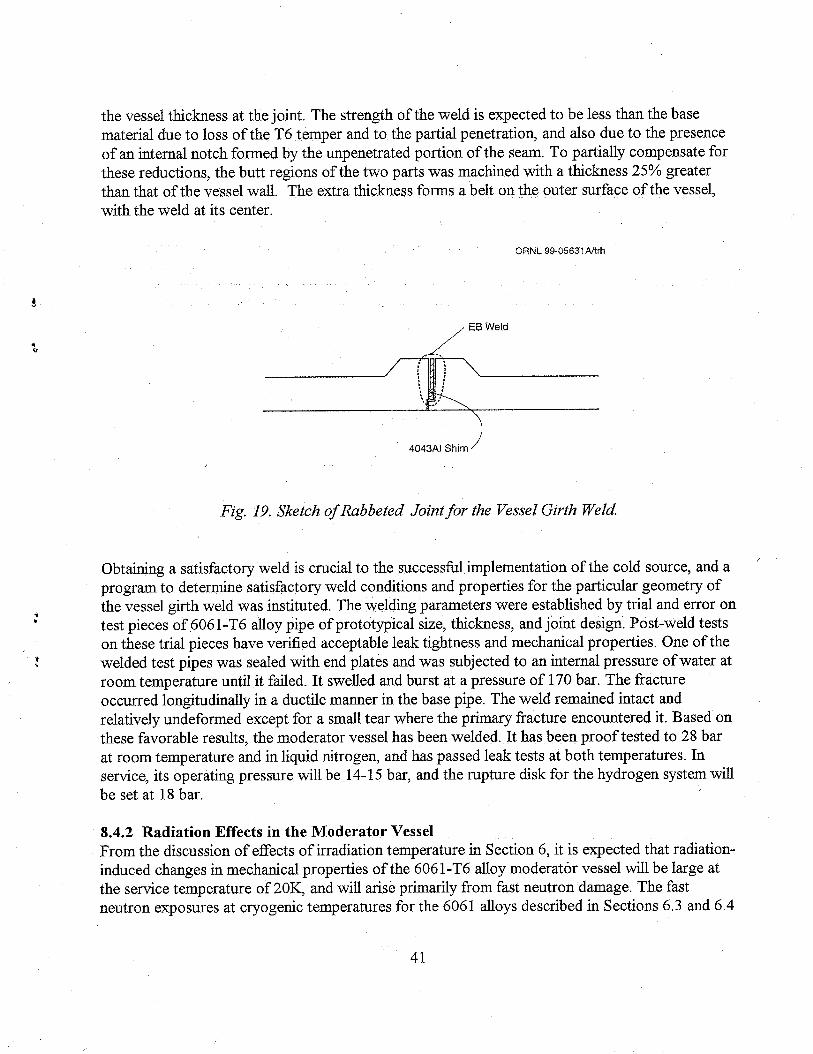
the vessel thickness at the joint. The strength of the weld is expected to be less than the base material due to loss of the T6 temper and to the partial penetration, and also due to the presence of an internal notch formed by the unpenetrated portion of the seam. To partially compensate for these reductions, the butt regions of the two parts was machined with a thickness 25% greater than that of the vessel wall. The extra thickness forms a belt on the outer surface of the vessel, with the weld at its center.
ORNL 99.05631A/trh
5
, EB Weld
4043Al Shim /
Fig. 19. Sketch of Rabbeted Joint for the Vessel Girth Weld.
Obtaining a satisfactory weld is crucial to the successfY,implementation of the cold source, and a program to determine satisfactory weld conditions and properties for the particular geometry of the vessel girth weld was instituted. The welding parameters were established by trial and error on test pieces of 606 l-T6 alloy pipe of prototypical size, thickness, and joint design. Post-weld tests on these trial pieces have verified acceptable leak tightness and mechanical properties. One of the welded test pipes was sealed with end plates and was subjected to an internal pressure of water at room temperature until it failed. It swelled and burst at a pressure of 170 bar. The fracture occurred longitudinally in a ductile manner in the base pipe. The weld remained intact and relatively undeformed except for a small tear where the primary fracture encountered it. Based on these favorable results, the moderator vessel has been welded. It has been proof tested to 28 bar at room temperature and in liquid nitrogen, and has passed leak tests at both temperatures. In service, its operating pressure will be 14-15 bar, and the rupture disk for the hydrogen system will be set at 18 bar.
’
8.4.2 Radiation Effects in the Moderator Vessel From the discussion of effects of irradiation temperature in Section 6, it is expected that radiation- induced changes in mechanical properties of the 606 1 -T6 alloy moderator vessel will be large at the service temperature of 2OK, and will arise primarily from fast neutron damage. The fast neutron exposures at cryogenic temperatures for the 6061 alloys described in Sections 6.3 and 6.4
41

and Figs. 15 and 17 reach to only 1 x 10²³n.m=L and are small in comparison to the exposure the HFJR moderator vessel is expected to tolerate. At most, they are the ‘equivalent of a half hour to five days in the neutron field of the vessel. At the portion of the moderator vessel tip facing the reactor core, the neutron fluxes for 100 MW reactor power are estimated [ 181 to be 5.7 x 1 Or7 n.mm2.sm1 (E > 0.1 MeV) and 6.6 x 10” n.mm2.s-’ (thermal). Assuming the fast flux with E >l MeV to be half of the flux with E >O. 1 MeV, the fluence of neutrons with energies >1 MeV after 8 years service at 80% duty factor will be about 6 x 1O25 n.me2. However, the accumulation of this fluence will include frequent pauses to change the reactor fuel, during which action will be taken to reduce or remove the point defects accumulated in the vessel walls by performing anneals on the vessel at near room temperature. Therefore, much of the radiation-induced changes in mechanical properties will be relieved, too. Nonetheless, an uninterrupted fuel cycle will last 23 days during which the fast neutron fluence on the vessel will reach about 6 x 1O23 n.mW2 (Dl Mev). This is six times higher than the highest fluence in Figs. 15 and 17, and the irradiation temperature will be 20K, which means we can certainly assume that the changes in mechanical properties of the vessel at 20K will be significantly greater than those in Figs. 15 and 17. It would be prudent to accept that the vessel will be greatly strengthened but will have no ductility at 20K at the end of a me1 cycle. As discussed earlier under Section 6.7, no exceptional radiation effects are envisaged for the girth weld, but prudence dictates that we should consider it as the most likely location for problems.
The vessel is pressurized internally, which imposes a tensile hoop stress on the vessel walls and invokes the question of creep. The highest stress is expected to be 55 l&Pa, This stress is well below the yield strength of 275 MPa or more at temperatures below 125”C, so there will be no significant thermal creep. For most of its life the vessel will be at a temperature of 20K (-253°C) . at which there will be neither thermal creep nor radiation-assisted creep. The greatest potential for occurrence of creep is expected to be during the rising temperature transient when the vessel is undergoing a scheduled room temperature anneal to relieve radiation damage. At this stage, the reactor will be off and generation of point defects will have ceased. But the excess point defects stored in the vessel wall will be mobile for a while until they are erased, and during their short period of movement they might, perhaps, cause a spurt of creep. This creep, if it occurred, would be akin to radiation-assisted creep, for which, as we have seen in Section 6.6, there is no reliable guidance to the degree of creep. Two factors mitigate the potential for significant creep ensuing from this recovery phase. One factor is the strong likelihood that many of the stored f?npds will be annihilated by mutual recombination and will not be available to participate in creep. The other factor is the short duration of the elimination processes, only a day or so. So the possibility of substantial creep during the recovery anneal is probably small. The girth weld, being the softest part of the vessel, will be the most susceptible to creep but is only a narrow region and is constrained by the stronger unwelded portions of the vessel.
.
Radiation effects on mechanical properties of the vessel due to silicon generated from low energy neutrons are expected to be small compared to the effects of fast neutrons in the early life time of the vessel, but will accumulate with exposure time regardless of the periodic anneals, as discussed below.
42
8.4.3 Periodic In-Situ Anneals of the Vessel If the moderator vessel and its ingress and outlet pipes were maintained permanently at a temperature .of 20K during the life of the cold source the radiation displacement damage described in Item 6.2.1, and its associated stored energy, would continue to accrue over the lifetime of the vessel. Nobody has attempted to determine experimentally the consequences of unlimited damage accrual at cryogenic temperature, but one obvious possibility is a sudden, uncontrollable release of the stored energy, possibly with undesirable effects on the integrity of the moderator vessel. The usual way of handling this issue is to play it safe by incorporating a controlled relief process at prescribed intervals.
?
* P
The operating procedure for the HFIR cold source will include periodic anneals of the moderator vessel at near room temperature to release stored point defects. Because the vessel is aluminum and not some higher melting point material, this moderate temperature anneal will be sufficient to eliminate the point defects, as described in Sections 6.2.1 and’6.3. It will also partially restore the unirradiated mechanical properties of the vessel. No harmful effects have been reported from such anneals, and they are used routinely in other cold neutron sources. For the HFIR cold source, the anneals will be performed during fuel changes and will be accomplished by allowing the moderator in the vessel to warm up for a day or so. Full restoration of properties may not be achieved because transmutation-produced silicon will be retained, and it will cause some hardening as described in Section 6.2.1. The amount of hardening retained from the silicon during the anneal will be small compared to the displacement damage hardening at low temperature. But it will continue to build up fi-om one fuel cycle to another, and its long-term consequences to the properties of the vessel material other than hardening are not known. We have considered combating this accumulative hardening process by introducing high temperature anneals at intervals to induce coarsening of the silicon precipitate. Annealing experiments with solution- treated-and-quenched Al-S1 alloys [66,67] and neutron irradiated aluminum [68] have shown that temperatures of 200°C or higher are required to ensure the appropriate coarsening in short times. A temperature of 200°C could be achieved from decay heat by reducing the hydrogen flow rate or the degree of refrigerator cooling. Fig. 4 shows that a 200°C treatment for a few hours or so would not seriously jeopardize the T6 temper condition of 6061 alloy. However, temperatures above 200°C would weaken the alloy. Such high temperatures would also introduce heavy precipitation of the transmutant silicon on grain boundaries, raising the prospect of grain boundary weakening and corrosion. Since movement of silicon atoms must occur to cause coarsening, some degree of grain boundary segregation of silicon can be expected even at 200°C. It is known that when tensile tests are performed on heavily neutron irradiated aluminum at temperatures above 150°C the fracture mode becomes intergranular. For the inaccessible irradiated cold source vessel there would be no way to ascertain the effectiveness of a 200°C annealing treatment, to show that it is doing more good than harm. Nor would there be direct instrumentation in the vessel itself to measure and control the temperature at 2OO’C. Thus, this route can not be recommended at this time.
No alternative relief strategy for the accumulating silicon is obvious. The French do not perform high temperature anneals on their A5 aluminum cold source vessel in the Reacteur Haut Flux at
43

Saclay, which has the highest irradiation exposure of any existing cold source. It receives periodic room temperature anneals to relieve the point defect damage but no special treatment to defray the effects of the silicon. The French have decided to live with the accumulated silicon and accept its consequences. Their vessel has operated without mishap. It seems that the French laissez-faire philosophy towards the accumulating silicon may be the most practical one to adopt for the HFIR cold source.
8.5 The H, Lines The supercritical hydrogen gas moderator is conducted to and from the moderator vessel by inlet and outlet pipes of 6061-T6 alloy, one located at 9 o’clock and the other at 3 o’clock positions close to the inside surface of the vacuum tube. The pipes are 14.3 mm OD and have 0.8 mm thick walls. Hangers and spacers keep the pipes in fixed positions and bear their weight. The pipes are welded to the integral pipe stems on the vessel, and the vessel is supported as a cantilever by the pipes. The nearest support hanger for the pipes is positioned about 630 mm from the girth band of the moderator vessel; the next is at 863 mm.
With regard to the welds connecting the pipes to the moderator vessel, there will not be a continuous line of sight to permit electron beam welding. So the welds will be TIG welded manually. The wall thickness at the abutments will be locally thickened to 1.6 mm, and a 4043 Al filler wire will be used: The extra thickness will counter the loss in strength at the weld.
Concerning radiation effects on the H, lines, the lines will receive less irradiation exposure than the high flux tip of the moderator vessel, and the exposure will decrease considerably along the length of the lines towards the reactor periphery. Nevertheless they will become irradiation hardened for some considerable distance along their length. Estimated fast neutron fluxes [69] at the 630 mm pipe hanger and the 863 mm hanger locations are 1.1 x 10¹⁷ n.m2.sm1 and 1.2 x 10¹⁵ n.m-2.s-‘, E > 1 MeV. The fast neutron fluences accumulated at these locations during a 23 day fuel cycle will be 2.2 x 1O23 n.mm2 and 2.4 x 10²’ n.mm2. From Figs. 15 and 17 and the foregoing discussion of cryogenic irradiation effects, it is evident that these fluences will cause significant hardening and loss of ductility in the 6061-T6 pipes. During the regular anneals of the moderator vessel at each fuel change the radiation damage in the pipes will be partially annealed, too.
The cantilevered nature of support for the vessel by the H, lines raise some questions with regard to sagging and fatigue in the H2 lines, particularly at the welds and the first hanger strap. The natural vibrational frequency is estimated to be about 9 Hz.[70], and the stresses generated by the effective 566g weight of the moderator vessel and its contents are only about 14.5 Mpa. This stress level is well below the fatigue limit for unirradiated 606 1 -T6 shown in Fig. 9. To prevent sagging, which would allow the cold vessel to come into contact with the warm vacuum tube, three short, pointed stand-off ridges are machined onto the surface of the moderator vessel at 2:00, 6:00, and 10:00 o’clock positions. The 6:00 o’clock ridge is designed to just make line contact with the vacuum tube. The other two ridges have a clearance of 1 mm.
44

9.0 References
1)
2)
4)
5)
6)
7)
? 8)
:
9
10)
11)
D. L. Selby et al, “High Flux Isotope Reactor Cold Source Preconceptional Design Study Report”, Oak Ridge National Laboratory Report ORNL/TM-13 136, December 1995. Also; D. L. Selby et al, ‘High Flux Isotope Reactor Cold Neutron Source Reference Design Concept”, Oak Ridge National Laboratory Report ORNL/TM-13498, May 1998.
D. J. Alexander, “Materials for Cold Neutron Sources: Cryogenic and Irradiation Effects”, pp 32 1-34 1 in Proceedings of International Workshop on Cold Neutron Sources, Los Alamos, New Mexico, March 5-8, 1990, LA-12146-C/UC-413, Los Alamos National Laboratory Report, August 199 1.
“Metals Reference Book, Fifth Edition”, Eds. C. J. Smithells and E. A. Brandes, Pub. Butterworths, London and Boston, 1976.
“Metals Handbook, Ninth Edition, Vo13, 1980, and Tenth Edition, Vol2”, 1990, ASM International, Metals Park, Ohio.
“Handbook of Chemistry and Physics, 77th Edition”, Ed. D. R. Lide, Pub. CRC Press, New York, 1996- 1997.
E. F. Sturken and C. W. Krapp, “Radiation-Induced Distortion and Swelling of Magnesium”, pp.996- 10 17 in Electron Microscopy and Structure of Materials, Fzfth Internat. Symp., University of California Press, Berkeley, 1972.
Cracking of the HFR beam tubes was detected in 198 l-2. Details have been made available to the technical community but no published references are available.
J. Lijbrink, H. J. von Grol, F. Dekker, and W. van Witzenburg, “Effects of Neutron Irradiation on the Mechanical Properties of a 5154-O Type Aluminum Alloy”, pp.765-778 in Effects of Radiation on Materials: Eleventh Conference, ASlYiMSliD 782, Amer. Sot. for Testing and Materials (1982).
M. I. de Vries and M. R. Cundy, “Results From Post-Mortem Tests With Material From the Old Core Box of the High Flux Reactor (HFR) at Petten”, pp. 1-9 in proceedings of Intebzational Symposium on Research Reactor Safety, Operations and Modzfications “, Chalk River, Canada, 23-27 October; 1989, pub. IAEA-SM3 10/69P.
A. Jostsons and R. T. King, “Transmutation-Produced Mg,Si Precipitation in an Irradiated Al-2.5%Mg Alloy”, Scripta Met, 6 (1972) 447-45 1.
R. T. King and A. Jostsons, “Irradiation Damage in a 2.2 Pet Magnesium-Aluminum Alloy”, Met. Trans. 6A (1975) 863-868.
45

12)
13)
14)
15)
16)
17)
18)
1%
20)
21)
22)
K. Farrell, “Microstructure and Tensile Properties of Heavily Irradiated 5052-O Aluminum Alloy”, J. Nucl. Mater. 97 (1981) 33-43.
K, Farrell, “Response of Aluminum and its Alloys to Exposure in the High Flux Isotope Reactor”, pp. 73-76 in Dimensional Stability andMechanicaZ Behaviour of Irradiated IMetals and Alloys, Proceedings of Brighton Conference, April 1 l- 14, 1983, British Nuclear Energy Society, London (1983).
K. Farrell, J. 0. Stiegler and R. E. Gehlbach, “Transmutation-Produced Silicon Precipitates in Irradiated Aluminum “, Metallography 3 (1970) 275-284.
K. Farrell, J. Bentley, and D. N. Braski, “Direct Observation of Radiation-Induced Coated Cavities”, Scripta Met. 11 (i977) 243-248.
J. R. Weeks, C. J. Czajkowski and K. Farrell, “ Effects of High Thermal Neutron Fluences on Type 6061 Aluminum”, pp. 1168- 1182 in Effects of Radiation on Materials: I6th International Symposium, ASM-STP 1175, Amer. Sot. for Testing and Materials (1993).
K. Farrell, “A Spectral Effect on Phase Evolution in Neutron-Irradiated Aluminum?“, Mat. Res. Sot. Symp. Proc. Vol. 373 (1995) 165-170.
J.Bucholz, Computer Physics and Engineering Division, ORNL, private communication, 27 January, 1998.
J. R. Weeks, C. J. Czajkowski and P. R. Tichler, “ Effects of High Thermal and High Fast Fluences on the Mechanical Properties of Type 6061 Aluminum in the HFBR”, pp. 441-452 in Effects of Radiation on Materials: 14th International Symposium (VoZ. I.,ASm-STP 1046, Amer. Sot. for Testing and Materials (1990).
K. Farrell and R. T. King, “Tensile Properties of Neutron-Irradiated 6061 Aluminum Alloy in Annealed and Precipitation-Hardened Conditions”, pp. 440-449 in Effects of Radiation on StructuraZMaferiaZs, ASmSTP 683, Amer. Sot. for Testing and Materials (1979).
R. T. King, A. Jostsons and K. Farrell, “Neutron Irradiation Damage in a Precipitation- Hardened Aluminum Alloy”, pp. 165- 180 in Effects of Radiation on Mcrostvucture and Mechanical Properfies of Metals and Alloys, ASXb!STP 529, Amer. Sot. for Testing and Materials (1973).
K. Farrell and A. E. Richt, “Postirradiation Properties of the 6061-T6 Aluminum High Flux Reactor Hydraulic Tube”, pp. 3 1 l-325 in Properties of Reactor Structural AZZoys After Neutron or Particle luradiation, ASilk?-STP 570, Amer. Sot. for Testing and Materials (1975).
46

23) “Use of 6061-T6 and 6061-T651 Aluminum for Class 1 Nuclear Components, Section III, Division 1 ‘I, Cases of Boiler and Pkessure Vessel Code, Supplement 1 O-NC, Case N-5 19, American Society of Mechanical Engineers, New York, 1994.
24) K. Farrell, “Assessment of Aluminum Structural Materials for Service Within the ANS Reflector Vessel,‘, Oak Ridge National Laboratory Report ORNL/TM- 13 049, Aug. 1995.
25) “Aluminum Standards and Data 1990”) Tenth Edition, The Aluminum Association, Washington, D. C., 1990.
R
; %
26) H.R. Voorhees and J.W. Freeman, “Report on the Elevated-Temperature Properties of Aluminum and Magnesium Alloys’,, ASTM STP 29 1, Amer. Sot. Testing Materials (1960).
27) Structural Alloys Handbook, Vol. 3, Metals and Ceramics Division Information Center, Batelle Memorial Institute, Columbus, OH (1989).
28) J.E. Dorn and T.E. Tietz, “Creep and Stress-Rupture Investigations on,Some Aluminum Alloy Sheet Metals”, Proc. of ASTM, 49 (1949) 8 15-83 1.
29) W.C. Leslie, J.W. Jones and H.R. Voorhees, “Long-Time Creep Rupture Tests of Aluminum Alloys”, Journ. Testing and Evaluation, 8 No. 1 (1980) 32-40.
30) T.A. Roach and H.R. Voorhees, “Stress Relaxation of Aluminum Alloys in Tension”, in ASME Reports of Current Work on Behavior of Materials at Elevated Temperatures, Ed. A.O. Schaefer, Material Properties Council, Inc., New York, NY10017, Nov. 18-21, 1974.
3 1) M.J. Manjoine and H.R. Voorhees, “Compilation of Stress-Relaxation Data for Engineering Alloys,‘, ASTM Data Series Publications IDS60 (1982)) Amer. Sot. for Testing and Materials.
32) J. A. Neck, Jr., “Heat Treatment and Aging 61s Sheet”, The Iron Age, April 24 (1947) 48- 54.
33) W. F. Smith, “The Effect of Reversion Treatment on Precipitation Mechanisms in an Al- 1.35 at. pet. Mg,Si Alloy”, MetTrans. 4 (1973) 2435-2440.
34) H. E. McCoy, Jr. and J. R. Weir, Jr., “Influence of Irradiation on the Tensile Properties of the Aluminum Alloy 6061 ‘I, Nuclear Science and Engineering, 25 (1966) 3 19-327.
3 5) K. Farrell, Unpublished data, Oak Ridge National Laboratory, 1998.
36) “Handbook on Materials for Superconducting Machinery”, MCIC-FIB-04, Metals and Ceramics Information Center Battelle, Columbus, Ohio, Jan. 1977.
47
37) F. R. Schwartzberg, S. H. Osgood, R D. Keys, and T. F. Kieffer, “Cryogenic Materials Data Handbook,’ Technical Documentary Report No. ML-TDR-64-280; PB 171809 (Revised), Air Force Materials Laboratory, Wright-Patterson Air Force Base, Ohio, 1964.
3 8) J. G. Kaufman and M. Holt, “ Evaluation of Fracture Characteristics of Aluminum Alloys at Cryogenic Temperatures”, pp. 77-85 in Advances in Cryogenic Engineering, Vol. 10, 1965.
39) F. G. Nelson and J. G. Kaufman, “Plane’ Strain Fracture Toughness of Aluminum Alloys at Room and Subzero Temperatures”, pp. 27-3 9 in Fracture Toughness Testing at Cryogenic Temperatures, ASTiWSTP 496, Amer. Sot. for Testing and Materials, 1971. I.
1 40) F. G. Nelson, J. G. Kaufman, and E. T. Wanderer, “Tensile Properties and Notch J
Toughness of Groove Welds in Wrought and Cast Aluminum Alloys at Cryogenic Temperatures”, pp. 71-82 in Advances in Cryogenic Engineering, Vol. 14, 1969.
41) M. P. Hanson, G. W. Stickley, and H. T. Richards, “Sharp Notch Behavior of Some High- Strength Aluminum Alloys and Welded Joints at 75, -320, and -423 F”, pp. 3-23 in Symposium on Low-Temperature Properties of High-Strength Aircraft andMissile Materials”, AST&fSTP 287, Amer. Sot. for Testing and Mater., 1960.
42) D. J. Alexander, “The Effects of Irradiation on the Mechanical Properties of 606 1 -T65 1 Aluminum Base Metal and Weldments”, pp. 1027- 1044 in Effects of Radiation on Materials: 18th International Symposium, ASTMSTP 1325, Amer. Sot. for Testing and , Mater., Amer. Sot. for Testing and Mater., 1999.
43) J. G. Kaufman and E. W. Johnson, “New Data on Aluminum Alloys for Cryogenic Applications”, pp. 637-649 in Advances in Cryogenic Engineering, Vol. 6, 196 1.
r; c,
44) 0. S. Oen, “Cross Sections for Atomic Displacements-in Solids by Fast Electrons”, ORNL- : 4897- UC-34-Physics, Oak Ridge National Laboratory, August, 1973.
45) T. A. Gabriel, B. L. Bishop and F. W. Wiffen, “Calculated Irradiation Response of Materials Using Fission Reactor ( HFIR, ORR, and EBR-II ) Neutron Spectra”, ORNL/TM-636 1, Oak Ridge National Laboratory, August, 1979.
46) K. Farrell and J. T. Houston, “Suppression of Radiation Damage Microstructure in Aluminum by Trace Impurities”, J. Nucl. Mater. 83 (1979) 57-66.
47) A. W. McReynolds, W. Augustyniak, and M. McKeown, “Neutron Irradiation Effects In Cu and Al at 80R’, Phys. Rev. 98-2 (1955) 418-425.
48) D. Keefer and A. Sosin, “Electron Irradiation Hardening of Aluminum’, Acta Met. 12
48
(1964) 969-978.
49) L. Bichorol, P. Brauns, and G. Claudet, “Effets D’Irradiations Neutroniques A 27K Sur Les Caracteristiques De Traction A 27K De 1’Aluminium”, pp. 643-650 in Progress in Refrigeration Science and Technology, Vol. 1, 1973, Pub. AVI Publishing Co. Inc., USA.
50) Messrs. Astruc, Harig, Sauvigne, and Verdier, “Source Froide Du Reacteur A Haut Flux, Projet De Realisation Et Rapport De Surete”, Al 91 PCBT 69/l 186, 29 Dec. 1969, Institut Max Von Laue-Paul Langevin, Saclay, France.
5 1) K. Farrell and S. T. Mahmood, Unpublished data, Oak Ridge National Laboratory.
52) W. Lohmann, A. Ribbens, W. F. Sommer and B. N. Singh, “Microstructure and Mechanical Properties of Medium Energy (600-800 MeV) Proton Irradiated Commercial Aluminum Alloys”, Radn. Eff. IO1 (1986) 283-299.
53) Z. H. Ismail, “Effect of Low Neutron Irradiation on the Mechanical Properties of an AlMgSi Alloy”, Radn. Eff. and Defects in Solids 112 (1990) 105-l 10.
54) K. Farrell and S. T. Mahmood, “Refutation of Radiation Softening in Precipitation- Hardened Aluminum”, presented orally at the Symposium on Radiation Materials Science in Technology Applications, TMS Annual Meeting, Anaheim California, Feb. 4-8, 1996.
55) W. F. Sommer and J. F. Stubbins, “LANL/APT Topical Report Materials Safety Experiment”, LA-UR-93 -2850, Los Alamos National Laboratory, 1993.
k 56) Z. H. Ismail and B.Birt, “Post-Irradiation Mechanical Properties of an AlMgSi Alloy”, J.
Nucl. Mater. 218 (1995) 289-292.
57) S. Maloy, “Target Blanket and Materials ED&D Materials Program. A Preliminary Report: The Change in the Mechanical Properties of Inconel718,304L, and 3 16L Stainless Steel and Al 606 1 After Irradiation at the LANSCE Accelerator”, TPO-RGN-00 13, Los Alamos National Laboratory Report, 28 January 1999.
58) L. Albertin and J. DeMastry, “Post-Irradiation Tensile and Fracture Toughness Properties of 606 l-T65 1 Aluminum Plate”, Paper presented at Symposium on Effects of Radiations on StructuvaZMateuiaZs, Los Angeles, Ca., 25-30 June 1972.
59) E. R. W. Jones, W. Munro and N. H. Hancock, “The Creep of Aluminium During Neutron Irradiation”, J. Nucl. Energy, 1 (1954) 76-86.
60) S. Sh. Ibragimov, E. S. Aitkhozhin and Y. S. Pyatiletov, Radiation-Induced Creep of Aluminum and Copper”, pp. 5-10 in’InJZuence of Radiation on Materials Properties: 13th
,. ‘49

International Symposium (Part II), ASN-STP 9.56, Amer. Sot. for Testing and Materials (1987).
6 1) K. Farrell, unpublished data, Oak Ridge National Laboratory.
62) R. T. King, K. Farrell and A. E. Richt, “Creep Properties of Irradiated Aluminum Alloys From the HFIR Surveillance Program”, Nuclear Metallurgy 19 (1973) 133-152.
63) E. T. Smith, “Measuring the Combined Effects of Nuclear Radiation and Cryotemperatures on the Tensile and Shear Properties of Materials”, Advances in Cryogenic Engineering, 11 (1966) 478-485.
64) J. J. Lombardo, C. E. Dixon, and J. A. Begley, “Cryogenic Radiation Effects on NERVA 3 Structural Materials”, pp. 625-652 in Effects of Radiation on StructuralMaterials, ASW- STP 426, Amer. Sot. for Testing and Materials (1967).
65) R. B. Rothrock, Research Reactors Division, ORNL, private correspondences, 15 January, 1998, and 4 March, 1998.
66) H. S. Rosenbaum and D. Turnbull, “Metallographic Investigation of Precipitation of Silicon from Aluminum”, Acta Met. 7 (1959) 664-674
67) H. Matyja, K. C. Russell, B. C. Giessen, and N. J. Grant, “Precipitation of Silicon from Splat-Cooled Al-S1 Alloys”, Met. Trans. 6A (1975) 2249-2252.
68) A. Jostsons, E. L. Long, Jr., J. 0. Stiegler, K. Farrell, and D. N. Braski, “Annealing of Voids in Aluminum”, ORNL-TM-3494, Oak Ridge National Laboratory Report, Oct. 1971. I v
69) Private communications from J.Bucholz, Computer Physics and Engineering Division, ORNL, 18 September, 1999, upgraded 6 January, 2000. :
70) S. J. Chang, “Thermal Stresses and Natural Frequencies for the Moderator Piping System’, Calculation ID: C-HFIR-2000-047, Oak Ridge National Laboratory, August 2000.
50
oRNL/Th&99-208
MATERIALS SELECTION FOR THE HFIR COLD NEUTRON SOURCE
INTERNAL DISTRIBUTION
1. E. E. Bloom 2. L. W. Boyd 3. D. H. Cook 4. M. B. Farrar 5. K. Farrell 6. G. F. Flanagan 7. T. A. Gabriel 8. L. L. Horton 9. J. R. Inger 10. A. T. Lucas 11. L. K. Mansur 12. T. J. McManamy 13. J. B. Roberto 14. D. L. Selby 15. S. J. Zinkle
EXTERNAL DISTRIBUTION
16. L. W. Boyd, USDOE-ORO, Oak Ridge, TN 3783 1 17. H. R. Persinger, USDOE-ORO, Oak Ridge, TN 37831 18. P. Dehmer, USDOE, Office of Basic Energy Sciences, Germantown, MD 20874-1290 19. R. J. Gottschall, USDOE, Division of Materials Sciences and Engineering, Germantown, MD
20874-1290 20. I. Thomas, USDOE, Division of Materials Sciences and Engineering, Germantown, MD
20874-1290 21. DOE, Office of Scientific and Technical Information, P. 0. Box 62, Oak Ridge, TN 3783 1 22. G. Bauer, Forschungszentrum Julich, Germany 23. J. M. Carpenter, Argonne National Laboratory 24. E. Gutsmiedl, TU-Muenchen, Germany 25. T. Broome, ISIS, Didcot, United Kingdom
5i