materials requirements to support research for the
TRANSCRIPT

MATERIALS REQUIREMENTS TO SUPPORT
RESEARCH FOR THE GENERATION IV
SYSTEMS DEVELOPMENT
(VHTR, GFR, SFR)
Philippe BILLOT (DDIN), Jean-Louis SERAN (DMN)
1. Introduction For the development of future nuclear energy systems, CEA expressed a priority interest on fast neutron systems with a closed fuel cycle and a complete recycling of actinides. CEA favours an approach through the research of innovations to resolve remaining key technical issues of sodium cooled fast reactors, and a basic R&D on specific technology breakthroughs for the Gas Fast Reactor.
Furthermore, CEA proposes to participate to the development of system broadening the range of nuclear production beyond the generation of electricity, such as water splitting for hydrogen production, high temperature process heat and desalination. For this purpose, the Very High Temperature Reactor (VHTR) developed in close cooperation with French industrial partners AREVA and EDF can produce electricity at high efficiency and hydrogen by using thermochemical iodine-sulfur process or by using high temperature electrolysis.
The VHTR evolves from HTGR experience and extensive international database that can support its near term development. Furthermore, the research associated to the ‘Materials and Components’ program or for the hydrogen project is expected to support both the VHTR and GFR gas cooled reactor systems, thus allowing sequenced development phasing for the VHTR and next the GFR which requires a longer R&D for the fuel development.
This document describes the requirements for the selection and the qualification of the main materials and components of the three ‘Generation IV’ systems (VHTR, GFR, SFR). Furthermore, the definition of the VHTR design characteristics has to be considered as a key issue to propose guidelines to perform the experimental program for the materials developments of both gas cooled VHTR and GFR systems.
In particular, the studies on the components such as the reactor pressure vessel, the hot pipings, the intermediate heat exchanger and the power conversion system in the helium environment can be considered as crosscutting issues.
1

2. MATERIALS REQUIREMENTS FOR THE VHTR SYSTEM AND COMMON DEVELOPMENT WITH THE GFR CONCEPT
2.1 VHTR plant concept description
The VHTR concept is a helium cooled, graphite moderated thermal neutron spectrum reactor with an outlet temperature of 950°C or higher. It is expected that the VHTR could produce either electricity with a direct or indirect cycle gas turbine or hydrogen and other process heat applications. The process heat version of all the systems requires an intermediate heat exchanger and a secondary circuit. The Framatome-ANP HTR concept is presently in the pre-conceptual design phase. The main plant parameters are recalled in Table 1, while Figure 1 presents the plant principle. The plant is designed for a 60 years life anticipated for Generation IV systems. The key VHTR technology design characteristics are the use of helium coolant, graphite moderator and refractory coated particle fuel. The helium coolant is inert and remains single-phase under all conditions.
The nuclear plant is based on the modular concept whereby the core is contained in a metallic pressure vessel designed to be able to radiate the residual heat in case of a major accident. This passive means by itself is sufficient to limit the fuel kernel temperature to less than 1600°C to ensure fuel particle integrity. The VHTR fuel must exhibit excellent performance in operating conditions (1300°C), burn-ups of about 15 to 20% Fissions per Initial Metal Atom (FIMA), and fluences of 6x1025 n/m2 (E > 0.1 MeV). The starting design for such a fuel is the Silicon Carbide (SiC)-Tri-Isotropic (TRISO) fuel. This fuel has shown excellent performance in the past in a number of HTR experimental reactors. The future objectives aim at assessing the SiC-TRISO fuel within the VHTR set of requirements, in particular the higher temperature feature, as well as developing new fuels that will exhibit even better performance at very high temperatures and high burn-ups (max. :1800°C, 30% FIMA).
For optimizing the power level of the core while meeting the previous passive safety requirement, the core has an annular configuration. In order to minimize core pressure drop and to simplify future spent fuel recovery, the hexagonal block type core concept has been retained. The hexagonal fuel elements are surrounded by identically sized solid graphite reflector elements mitigating the high energy fluxes and vertically supported at the bottom by a core support plate structure and laterally supported by a core barrel. The core is enclosed in a steel reactor pressure vessel. Control rod mechanisms are located in the reactor vessel top head and a shutdown cooling system provided for maintenance purposes is contained in the bottom head.
The reactor vessel and power conversion system are side by side and connected by a cross-vessel. The hot outlet helium flows from the reactor core to the PCS through a hot duct located in the center of the cross-vessel. Helium is cooled in the Power Conversion System (PCS) and returns to the reactor through the annulus formed between the cross-vessel outer shell and the central hot duct. The cooled helium flows up to an inlet plenum at the top of the core through the annulus between the reactor vessel and the core barrel. From the top inlet plenum, the helium is heated by flowing downwards through coolant channels in the fuel elements.
It should also be pointed out that the primary loop pressure is limited to 5.5 MPa. This has a strong impact on vessel wall thickness and vessel manufacturing due to thinner welds. This pressure level has been chosen so that the blower volumetric flow rate is similar to previously designed blowers. Should the feasibility for a larger volumetric flow rate blower prove feasible, without any negative impact, the pressure could still be lower. There are several alternative high-efficiency Brayton cycle gas turbine PCS and arrangement that could be used for the electricity production. Tow main concept options have been proposed by industrials : 1. The indirect cycle : Framatome-ANP is developing an original combined cycle concept with a
potential for very high efficiency, 47 % or more. In the secondary circuit coupled to the primary circuit by the IHX, a gas Brayton cycle is used to recover energy and convert it into electricity for the temperature range of 800°C to 900°C down to 600°C. Furthermore in the present combined cycle, all of the gas loop energy is recovered in the steam generator and passed to the steam cycle which
2

converts it efficiently down to the low temperatures of steam condensation. It must be noted that the gas loop net power production is about 80 MWe while the steam cycle produces about 200 MWe. In order to use conventional gas turbine technology and take advantage of the closed gas loop, nitrogen, which basically has identical properties to air, is chosen as the gas vector of the secondary circuit. To improve the heat exchange characteristics of the gas for the intermediate heat exchanger (IHX) design, a minor amount of helium can be added to the nitrogen. It hardly affects the turbo-machines design while decreasing heat surface transfer for the IHX. The operating pressure is chosen so that the IHX is normally operating with the same pressure on both sides. The turbomachines are actually a simpler adaptation of the conventional air combined cycle ones with a compression-expansion ratio of about 2. This means the gas turbine has only 3 stages and the compressor 8 or 9 stages (nitrogen is easier to compress). The maximum inlet temperature in the turbine is 800°C to 900°C.
2. The direct cycle : The direct Brayton cycle gas turbine power conversion system (GTMHR type)
contains a gas turbine, an electric generator, and gas compressors located on a common long vertically oriented shaft supported by magnetic bearings. The power conversion system also includes recuperator, precooler and intercooler heat exchangers. Heated helium flows directly from the reactor vessel into a gas turbine (30 to 40 compressions stages and 13 to 15 expansion stages) to drive the generator and gas compressors. From the turbine exhaust, the helium flows through the hot side of the recuperator through the precooler and then passes through low and high pressure compressors with intercooling. From the high pressure compressor outlet, the helium flows through the cold high pressure side of the recuperator, where it is heated for return to the reactor. The use of the direct Brayton cycle to produce electricity results in a net plant efficiency of approximately 48 %.
Turbocompressor
IHX600MWtcore
1000°C
He
950°C
HT isolation valve
80%N2 +20% He
Circulator
S.G.Steam CycleCondenser
Steam turbines
S.G.S.G.Steam CycleCondenserCondenser
Steam turbinesSteam turbines
H2 processtemperature
875°C
H2 processtemperature
875°C
H2 processtemperature
875°C
50MWt50
MWt
925°C
He
Power Conversion System PCS
Nuclear HeatSource NHS
400°C
5 MPa 5 MPa192 Kg/s
Figure 1- Plant Scheme of the Framatome-ANP Design
3

Table 1 - Approximate plant design parameters (Framatome-ANP Indirect Cycle)
Reactor Power 600 MWt Reactor Outlet Temperature 850°C to 950°C Reactor Inlet Temperature 355°C to 400°C Primary Coolant Flow Rate 190 to 240 kg/s Primary Coolant Pressure 5.5 MPa Reactor Vessel Material 9 Cr – 1 Mo or SA 508 Core Configuration 102 Columns, 10 blocks high. Fuel Particle Type SiC Coating
UCO or UO2 kernel Operating Max Fuel Temp. Guideline 1300°C Accident Peak Fuel Temp. Guideline 1600°C IHX Design Compact IHX Nominal Heat Load 608 MWt IHX Effectiveness 90 % IHX Primary Tin 850°C to 950°C IHX Tout 350°C to 400°C Secondary Fluid Nitrogen/Helium Mixture IHX Secondary Tout 800°C to 900°C IHX Secondary Tin 300°C to 350°C Secondary Flow Rate 614 kg/s Secondary Coolant Pressure 5.5 MPa
(GTMHR Direct Cycle)
Reactor Power 600 MWt Reactor Outlet Temperature 850° C Reactor Inlet Temperature 491° C Core Inlet /Outlet Pressures 7.07/7.02 MPa Helium Mass Flow Rate 320 kg/s Turbine Inlet/Outlet Temperatures 848/511°C Turbine Inlet/Outlet Pressures 7.01/2.64 MPa Recuperator Hot Side Inlet/Outlet 511/125°C Recuperator Cold Side Inlet/Outlet 105/491°C Net Electrical Output 286 MWe Net Plant Efficiency 48 %
4

2.2 Chemistry guidelines for the VHTR (VHTR, GFR crosscutting issue)
The corrosion of metallic materials in impure helium environment appears to be a key factor for the development of the VHTR and GFR system, to which collapse mechanisms and service life of components and structures are closely related. In spite of differences due to the selected materials for the core of the VHTR and GFR, chemistry of the primary and secondary circuit is studied in parallel for both systems.
The nature and concentrations of gaseous impurities in helium are set up by a dynamic balance between the rate of pollution (air ingress, water in-leakage, material degassing…), the release of corrosion products from materials of the primary circuits, the pollutants reaction with the hot parts of the core and the efficiency of the purification plant. The main impurities are H2, H2O, CO, CO2, N2 and CH4. Their partial pressures are in the range of few microbars to about hundreds of microbars. Even if the contamination level is extremely low, it nevertheless can cause corrosion of metallic materials at temperatures as high as 700 to 1000°C, which in turn will degrade the mechanical characteristics.
Generally speaking, alloys that are corrosion resistant at high temperature develop at their surface a compact, adherent and low growth rate oxide layer allowing the substrate to be subsequently protected. The peculiarity of the HTR environment is its low oxidising potential (mainly determined by PH2O/PH2) associated with a possibly significant carbon activity (related to PCO and in some cases PCH4).
The main corrosion effects are scale formation, internal oxidation and carburisation or decarburisation (decomposition of internal metallic carbides). The transfer of carbon between atmosphere and metal is of special concern because changes in the material carbon content can significantly impair the mechanical properties : carburisation results in low temperature embrittlement whereas decarburisation reduces the creep rupture strength.
Within the reactor, environmental parameters must thus promote the formation of a protective oxide layer on Ni and Fe base alloys. For each specific alloy (Cr activity, carbon content, minor element contents…), there is a set of specifications on the He composition that may warrant a safe behaviour at a given temperature.
Former HTR environments have been located on thermodynamical phase stability diagrams in order to evaluate the surface reactions that can occur on the surface of a Ni-base alloy exposed to HTR helium at high temperature and the different domains of predominance of these surface reactions. Based on this analysis, helium impurity concentration limits to maintain in the primary circuit, depending on the high-temperature range and with regard to the material aspects, are then recommended.
To summarize, safe behaviour of chromia forming Ni-base alloys in HTR helium requires at least three conditions dependent on the temperature and Cr activity in the alloy :
- PH20/PH2 > critical value to allow the formation of a protective Cr based oxide layer
- PCO > critical value to avoid the deep carburisation or complete decarburisation of the material
PCH4/PH20 < critical value to avoid the carburisation and oxide reduction by the methane.
Assuming values of surface Cr activities of about 0.3 under a protective oxide layer, order of magnitudes of the critical values to be specified for a safe behaviour of Ni-base alloy can be derived as follows :
- At 950° C, PO2> 2.10-23, PH20/PH2 > a few 10-4 and PCO > 150 µbar
- At 1000° C, PO2 > 10- 21, PH20/PH2 > a few 10-4 and PCO > 450 µbar
It is noticeable that former helium compositions that are safe at lower temperature (850°C) may not be safe at higher temperature. Moreover, higher the temperature, faster the kinetics of material degradation.Thus, higher the temperature, more strict must be the enforcement of the above helium specifications. This implies that the management of the impurities of the helium cannot be based on a
5

simple purification process which tends to remove all impurities from the environment without discrimination. In fact, some form of helium impurity control is required.
The target values of controlled impurity levels have to take into account the critical values presented above with additional safety margin to be evaluated from the variation of the operating parameters and the long term evolution of surface composition. Therefore the precise determination of the helium specification requires more work in areas such as modelling the Cr activity of the alloys and its evolution on the alloy surfaces with time, constraints related to the oxidation of graphite at high temperature and the possible formation of C dust and CO2 in the low temperature regions, and evaluation of the need for N2 specification.
A corrosion test program needs to assess materials, corrosion behaviour under primary and secondary HTR fluids (He with impurities and 80% N2 - 20% He mixture respectively).
Several metallic materials have been selected in the frame of current studies as candidate materials : alloys for circuits and heat exchangers (Alloy 800H coated with NiAl or NiCrAlY as anticorrosion bondcoat and thermal barriers, alloy 617, Haynes 230, Hastelloy X and XR as Ni-based solid solution strengthened alloy, ODS (Oxide Dispersion Strengthened) super alloys, steels for pressure vessel (9% Cr), alloys for turbine disk and blade (Udimet 720, Directionally Solidified grades).
Based on exposure tests, creep, bending-creep and creep-fatigue tests performed up to 1000°C under three types of controlled atmosphere : decarburising, carburising, slightly oxidising helium atmosphere, the objective is dual :
- To select the optimal material (including optimisation of the present ASME chemical composition to be introduced in the material specifications).
- To refine the safest range of environment (impurities composition and maximum temperature) in order to define a benign atmosphere for the materials behaviour.
2.3 Design of components and materials requirements to support the R&D The following major components (Figure 2) discussed in this report are the following :
• The fuel • The reactor pressure vessel • The reactor core structural elements • The reactor internals • The intermediate heat exchanger • The power conversion system including the turbine and recuperator • The hydrogen production subsystem
6

Primary Circulator
Isolation Valve
Reactor Building
Reactor Vessel
Plate IHX modules
IHX Vessel
Reactor Cavity Cooling System
Reactor Pressure Vessel
Control Rod Drive Stand Pipes
Power Conversion System Vessel
Floors Typical
Generator
Refueling Floor
Shutdown Cooling System Piping
Cross Vessel (Contains Hot & Cold Duct)
35m(115ft)
32m(105ft)
46m(151ft)
Hot duct
Figure 2 - Framatome-ANP ANTARES Project
7

2.3.1 Fuel TRISO fuel : The VHTR refractory-coated particle fuel identified as TRISO-coated particle fuel (Figure 3) consists of a spherical kernel of fissile fuel (< 20% enriched uranium), encapsulated in the following multiple layers of refractory coatings :
o Buffer layer (porous carbon layer) consists of void volume for fission gases and accommodating kernel swelling and fission recoil.
o Inner Pyrocarbon (IPyC) provides structural support for SiC and retains gaseous fission products. o Silicon Carbide (SiC) retains gaseous and metallic fission products. o Outer Pyrocarbon (OPyC) provides fission product barrier in particles with defective SiC, protect
SiC.
The overall diameter of standard TRISO-coated particles varies from few hundred microns up to about 1 mm. The fuel particles (thousands particles are dispersed in graphite to make fuel elements) are bonded into cylindrical fuel compacts nominally 12.0 mm O.D. X 50 mm long and loaded into hexagonal fuel blocks 360 mm across flats x 800 mm long. The highly corrosion-resistant TRISO coatings have to provide a high-integrity structure for retention of gaseous and metallic fission products to very high burnups (target burnup in the range of 15 to 20% FIMA (Fissions per Initial Metal Atom)), and fluences of 6x1025 n/m2 (E > 0.1 MeV). The coatings do not start to thermally degrade until temperature close to 2000°C are reached, then normal operating temperatures do not exceed about 1300°C and worst-case accident temperature are maintained below 1600°C. Manufacturing processes and quality control are critical to maintain very low levels of defects (<~5.0x10⁻⁵). Particle properties have to be such that the fission product release contribution from the manufacturing shall not be significantly exceeded by irradiation effects under normal or accidental conditions. Conservative upper limits for particle defects and failures during irradiation and during the worst-case accident are respectively about 2.10-4 and 5.10-4. In the longer term, the development of the Generation IV VHTR might consider a reactor with exit coolant temperatures above 1000°C for a more efficient and cost-effective production of hydrogen, or if ultra-high temperature gas turbines become available. At the same time, it may be desirable to reach very high burn-up (possibly as high as 30% FIMA). Then innovative fuel concepts must be considered even though the general principle of the TRISO structure will probably be kept. Enhanced TRISO fuel : During irradiation, some free oxygen atoms are produced that eventually combine with carbon from the porous graphite layer to make quantitative amounts of CO, in particular at high temperature, high power densities and ultra high burn-up. To limit that phenomenon it has been proposed an enhanced VHTR fuel that is composed of an oxicarbide kernel (UCO rather than a UO2 kernel) surrounded by a typical TRISO coating. The replacement of the SiC layer by a more refractory materials Zirconium carbide (ZrC) layer is a promising example of advanced fuel for the VHTRs, which enables an increase in power density and the coolant outlet temperature, since it shows a very good resistance to the transport of some fission products (like palladium). Nevertheless, additional R&D is needed for the development and qualification of the fuel or countermeasures for the easier oxidation of ZrC. New materials and new designs (geometry, layers) can also be combined.
8

Figure 3 - TRISO fuel particle
For any fuel category, the main R&D goals of the Fuel and Fuel Cycle project are :
• Development of fabrication process and control methods.
• Development of a fuel qualification plan that includes irradiation experiments, post-irradiation examination, and safety related tests.
• Development of fuel behaviour model(s) that take into account the many phenomena such as : grain growth at high burn-up, creep relaxation, swelling, growth and shrinkage of the pyrocarbon layers, kernel movement, CO production and fission gas release, solid fission product diffusion, thermo-mechanical and physico-chemical properties in order to predict structural failure of the TRISO layers and fission product release.
• Development of technologies for the management of waste generated by a VHTR system with special emphasis on the used graphite management and the conditions for the direct disposal of spent fuel.
• Development of treatment technologies for specific aspects of the spent fuel particle (removal of coatings, etc.) if direct disposal of the spent fuel is not feasible or if actinide recovery and recycle is pursued.
9

Table 2 - Fuel operating conditions and candidate materials
System Component Normal
Temp (°C) Abnormal Temp (°C)
Pressure (MPa)
Fluence (n/m2) (E>0.1 Mev)
Burn-up (%FIMA)
Design life (d)
Materials
VHTR
Fuel
1300°C
Peak T : 1600°C
5 MPa
6x1025 n/m2
15-20 % FIMA (Peak : 26% FIMA)
1500
UO2/SiC UCO/SiC
VHTR
Fuel
1500°C
Peak T : 1800°C
5 MPa
1.2x1026
n/m2
30% FIMA
2500
UO2/ZrC UCO/ZrC
2.3.2 Reactor Pressure Vessel (VHTR, GFR crosscutting issue) Preliminary VHTR designs with inlet temperatures ranging from about 400 (indirect cycle design) to 490°C (direct cycle design) have been developed. The RPV material must also support the extremely long lifetimes (60 years) anticipated for the Generation IV reactors. Scale-up of vessel fabrication (Figure 4) must include the use of very large forgings up to 450 tons, section thickness up to 250mm for vessel walls and 500mm for flanges, and heavy-section welding technology. The welding of large, thick-walled vessels is a key issue. In particular, the assembly of large rings fabricated steel may require a multi-pass, narrow gap procedure where the selection of filler metal and industrial operating processes are very important to minimize the weld metal and the size of the heat affected zones. The weldments must satisfy the required mechanical characteristics and have essentially no defects. To ensure that passive heat removal systems will function adequately for the VHTR, it is important to ensure that the component surfaces in the heat removal path (i.e. the RPV) develop and maintain a very high coefficient of thermal emissivity (> 0.80). The current options for the reactor pressure vessel materials are ferritic-martensitic steels with sufficient chromium to allow elevated temperature service and stabilize the microstructure from irradiation damage. The issues that will need to be addressed for the RPV-system include:
• The manufacturability and weldability of the very large pressure vessels. • The data base characterizing the effects of neutron irradiation on the nil-ductility transition
temperature and the fracture toughness. Tensile and very long term creep and creep-rupture properties of the plate, forging, weldments, and heat-affected zones of this class of materials will need to be extended since the materials that are currently approved for nuclear vessel applications above 370°C are limited.
• The very long term aging and structural integrity associated with a 60-year reactor life. • The environmental effects on oxidation, fatigue, fatigue crack growth and life at very high
temperature.
• The long term emissivity control on the vessel. • High temperature bolting.
10

SW1
SW2
SW3
Closure Head
Reactor Pressure Vessel
Chalon Factory manufacture :5 Packages
Figure 4 - Schematic of reactor pressure vessel Table 3 - Reactor Pressure Vessel operating conditions and candidate materials
System Component Normal
Temp (°C)
Abnormal Temp (°C)
Pressure (MPa)
Fluence (n/cm2) (E>0.1 Mev)
Design life (yr)
Materials
VHTR
Reactor Pressure Vessel
400 to 500°C
650°C for
50 h
5 MPa
3x10¹⁸ n/cm2
60
9Cr-1Mo (T91)
2 1/4Cr-1Mo
VHTR
Bolting
400 to 500°C
650°C for 50 h
5 MPa
+3x10¹⁸ n/cm2
60
Inconel 718 or 304 or 316 SS
2.3.3 Reactor Structural Elements The reactor core structural elements are made from graphite to provide neutron moderation as well as thermal and neutron shielding. In addition, it can also be employed as high temperature structural support to the fuel and cooling passage arrangement. The graphite components (Figure 5) are the fuel elements, replaceable reflector elements, permanent side reflector elements, and core supports. The dimensions are the followings : hexaedral prism (410x360x800 mm) for fuel assembly blocks and reflectors, columns (250 mm diameter) with a prismatic basis (h=1500mm) for core support assembly.
11

The blocks are submitted during operation to temperature fields leading to axial and radial thermal gradients. These gradients vary as a function of the block location within the core. This implies that over a column of assemblies, all the blocks do not have the same deformations which can create a bowing of the column. Another essential loading which must be combined with the previous one is the irradiation. This loading determines the life duration of the fuel assemblies and reflectors. The neutronical irradiation generates dimensional variations of the graphite block whose magnitude depends on the fluence, temperature and on the type of graphite. The thermal and mechanical properties are also modified by irradiation. This shows the importance of the choice of the graphite grade. Non appropriate graphite could lead to a modification of the coolant flow inside the core, an early ageing of structures and therefore a loss of the dimensional stability of the core structures with a possible jamming of blocks, making difficult the refuelling. It appears that the maximum stresses are obtained at the end of life at the periphery of the block where the temperature is maximum : the principal stress is equal to 6.2 MPa. The radial thermal gradient calculated is about 200°C. The first requirement is to have a dense graphite to reduce the volume of the moderator and to limit the amount of pores which tend to increase the oxidation process of graphite. The main mechanical requirement is to reduce the stress in the blocks induced on one hand by the temperature field and on the other hand by the irradiation-induced dimensional variation. Having a low level of thermal stresses implies to have a low Young’s modulus, a low thermal expansion coefficient, and a high thermal conductivity. A high strength Rm is also favourable as well as the dimensional variation under irradiation which should be as low as possible. The selection of properties will therefore result from a compromise. A high conductivity is required not only to reduce stresses during normal operation but also to favour the residual power evacuation in case of a loss of cooling system. As the thermal conductivity decreases with the neutron fluence, a minimum value has to be specified for the whole life of the component. The impurity content (B, Cl, Ni, N, Li, Co, Fe, Ti, V, S) can affect the behaviour in oxidation conditions. Graphites have to be purified and tests are necessary to define their reactivity in air. In addition, the impurities can bring contamination within the reactor circuit and affect the maintenance. For dismantling the residual activation of graphite must be as low as possible. The new currently available graphites are Graftech (UCAR) grade PCEA (a petroleum coke graphite) and SGL Grade NBG10, NGB17, NGB18 (pitch coke graphites). The main R&D activities for the graphite development will include : Properties data base before irradiation and after irradiation. These data must be obtained for the currently available graphite materials to support design activities for the VHTR. This requires a substantial graphite irradiation program. Data are required for the physical, mechanical and oxidation properties of graphites. Properties data must support the service conditions, including effects of temperature, helium gas (helium chemistry recommended for the primary coolant) as well as abnormal conditions (air and water ingress), and neutron irradiation effects. Irradiation creep data for the candidate graphites must be obtained. Moreover, the data must be statistically sound and take account of in-billet, between billets, and lot-to-lot variations of properties.
12

Control Rod Drive Assembly
Refueling Stand Pipe
Control Rod Guide tubes
Cold leg Core Coolant Upper Plenum
Central Reflector Graphite
Annular shaped Active Core
Outer Side Reflector Graphite
Core Exit Hot Gas Plenum
Graphite Core Support Columns
Reactor Vessel
Upper Plenum Shroud
Shutdown Cooling System Module Hot Duct
Insulation Module
Cross Vessel Nipple
Hot Duct Structural Element
Metallic Core Support Structure
Core Inlet Flow
Core Outlet Flow
Insulation Layer for Metallic Core Support Plate
Upper Core Restraint Structure
Control Rods
7m(23 ft)
23.7m(78ft)
2.2m(7ft)
8.2m(27ft) Dia Vessel Flange
Replaceablereflector (upper)
Permanent reflector
Replaceablereflector (lateral)
Fuel assembly
Replaceablereflector (central)
Replaceablereflector (lower)
6.84 m
13.6
0 m
Figure 5 - Core structural elements and graphite block Table 4 - Reactor Graphite components operating conditions and candidate materials System Component Normal
Temp (°C) Abnormal Temp (°C)
Pressure (MPa)
Fluence (n/cm2) (E>0.18
Mev)
Service time (yr)
Materials
VHTR
Fuel Element block
600 to 1250°C
Up to 1600°C
5 MPa
2.7x10²¹ n/cm2
2.8
PCEA (UCAR) NBG-
10,17,18 (SGL)
VHTR
Replaceable reflectors
1100°C
Up to 1600°C
5 MPa
2.7x10²¹ n/cm2
15
PCEA (UCAR) NBG-
10,17,18 (SGL)
VHTR
Permanent side/lower reflectors
600°C/1100°C
Up to 1200°C
5 MPa
2.0x10²⁰ n/cm2
60
PCEA
(UCAR) NBG-
10,17,18 (SGL)
VHTR
Core support
assembly
1000°C
Up to 1000°C
5 MPa
5.0x10¹⁸
n/cm2
60
PCEA (UCAR) NBG-
10,17,18 (SGL)
13

2.3.4 Reactor internals The reactor internals components support the graphite core assembly and maintain it in the required geometry for nuclear physics control and cooling. They include the core barrel, metallic core support plate, upper plenum shroud, and hot duct (Figure 6). The metallic structures will be exposed to inlet gas temperatures from about 500°C to about 600-650°C during normal operation. Hot Duct (GFR/VHTR crosscutting issue) : The Hot Duct assembly is composed of a structural duct separating the core entrance gas from the core exit gas, and an insulation assembly on the inside surface of the structural duct to protect it from direct contact with the 950°C core exit gas (Figures 7). The structural duct which separates the inlet gas flow from the core outlet gas flow withstands core pressure drop. The pressure bearing shell of the hot duct operates at the core return gas temperature (600°C for the VHTR). Temperatures rise to about 660°C under abnormal conditions. Therefore, Alloy 800H might be suitable for GFR or VHTR applications. The hot duct insulation subassemblies are made up of cylindrical metallic containers that contain fibrous insulation. The structural duct is insulated from the hot core outlet gas by these cylinders. The inner diameter surface is bathed in core exit gas (950°C for the VHTR, 850 °C for the GFR) and then must sustain the highest temperature of the primary coolant. The hot duct only rises in temperature about 30°C during a loss of forced circulation (LOFC) event followed by a conduction cooldown because it does not come in contact with the natural circulation flows in the core. The insulation assemblies are designed to be remotely removed and replaced if needed during the 60-year plant life. Alloy 800 H should be suitable for use in the GFR application while Ni-based alloys or carbon-carbon composites will be required for long-term 950°C service in the VHTR for the inner part of the hot duct.
14

Figure 6 - Metallic Internals Figures 7 - Hot gas duct cross-section
15

Core barrel / Bottom plate and supports (Figures 8 et 9) : The core barrel shell surrounding the reactor core and reflector structure, the bottom plate and supports operate at the core inlet temperature, 500°C for the GFR and 600°C for the VHTR. These temperatures increase to only 600°C and 700°C, respectively under abnormal conditions. Alloy 800H is suitable for this application. Additional consideration should, however, be given to radiation effects at 500°C to 600°C as the end-of-life fluence reaches 1019 n/cm2 (for the VHTR and higher for the GFR).
CORE BARREL
CORE SUPPORT
Figure 8 - Core barrel assembly Figure 9 - Core support structure Upper Plenum Shroud : Temperature of this component (Figures 5 and 6) is very high for the VHTR under abnormal conditions (1100°C). Carbon-carbon composite materials should be considered for this sub-component. Control Rods : The control and shutdown system of VHTR consists of two systems different in their functions :
- Reactivity compensation and emergency protection in the side replaceable reflectors. - Automatic control rods used only during start-up/shutdown and refuelling operation in the active
core at the boundary with the inner reflectors.
Both types of control rods have the same design : they consist of segments connected to each other. The segments contain the absorber material B4C, the upper part allowing the coupling with the drive mechanism. A ring type design is considered with a cooling from inside and outside (Figures 10). The cladding consists of two co-axial tubes containing absorbent materials (compact with B4C). The internal structure is annular to let the flow cooling the rod inside and should be able to link to segments to each other. This internal structure should allow a flexibility of the rod in order not to give too much stresses in case of earthquake. The following dimensions can be assumed for the cladding (co-axial tubes) : Tubes diameter Φe = 60 /120 mm, thickness between 4 and 8 mm, length of tubes = 500 mm.
16

Material of the rods has to be resistant to oxidation due to the presence of small quantity of O2 or H2O in normal operation and also oxidation due to air (or water) entry accidents. In a first assumption, a limit of 0.2 mg/g-h of burn off is proposed. The resistance to erosion has to be greater than that of the graphite blocks. The control rods shall operate in helium atmosphere under a maximum pressure of 71 bars and a helium speed of 35 m/s. The material has to withstand thermal stresses and should therefore offer at least the same level of thermal stability (thermal conductivity > 100 W/m°C). Regarding mechanics, a high mechanical resistance (> 80 MPa) has to be specified together with non brittle fracture behaviour and a high toughness (> 3 MPa m1/2). These properties cannot be reached by graphite. Under irradiation, the material should present stable, reasonable dimensional changes (< 1.2 %). Also to be consistent with graphite, the thermal conductivity shall not be too degraded (~30 W/m°C) and reach the level of graphite conductivity. The primary R&D concerns for carbon fiber reinforced carbon composites or silicon carbide fiber reinforced silicon carbide composites development depend on :
- The manufacturing of Cf/C or SiCf/SiC composite material components and their tests in operating or accidental conditions (temperature and environment).
- The radiation effects data base developed for the selected materials, insufficient neutron irradiation data existing to qualify these materials for reactor use.
- The mechanical and thermal properties, fracture behaviour, oxidation effects and post-irradiation tests required to establish design guidelines. The modelling of the material behaviour will need to consider the anisotropic nature of these materials.
Figures 10 - Control rod geometry and C/C composite microstructure
17

Table 5 - Reactor internals operating conditions and candidate materials System Component Normal
Temp (°C)
Abnormal Temp (°C)
Pressure (MPa)
Fluence (n/cm2) (E>0.1 Mev)
Service time (yr)
Materials
VHTR
Hot gas duct
-Pressure Bearing Shell
-Outer Shell of Insulation
Element
-Thermal Insulation
600°C
950°C
600-950°C
660°C
980°C
1000°C
5 MPa
2.0x10¹⁷ n/cm2
60
Alloy 800
C/C composites
Mix of Al2O3-SiO2 ceramic
fiber mat.
VHTR
Core Barrel or Bottom Plate and Supports
600°C
700°C
5 MPa
1.0x10¹⁹ n/cm2
60
Alloy 800
VHTR
Upper Plenum Shroud
600°C
~1200°C
5 MPa
1.0x10¹⁹ n/cm2
60
C/C composites
+ Al2O3-SiO2 ceramic fiber
mat.
VHTR
Operating
Control Rod
1100°C
Up to 1600°C
within 100 h
5 MPa
4.3x10²¹
n/cm2
30
C/C
composites SiC/SiC
composites
2.3.5 Thermal Insulation Materials and Coatings High temperature fibrous insulation must be used throughout the reactor system and the power conversion unit notably in the hot duct, upper plenum shroud and turbocompressor. Figures 7 show where insulation is required in the reactor metallic internals and hot gas duct. Insulation design studies have determined that the best insulation system for the VHTR/GFR application is the use of Al2O3 and SiO2 mixed ceramic fiber materials contained between metallic or carbon-carbon cover plates attached to the primary structure that requires insulation (Figure 11b). The materials chosen for these canisters will need to withstand 1000°C for 60 years, or up to 1200°C for up to 50 hours and then 1100°C for 100 hours during an LOFC followed by a conduction cooldown transient. For this reason, non-metallic materials such as carbon-carbon composites may be required. Development of coating systems will be also an important option (Figure 11a) as it becomes increasingly difficult to combine mechanical strength with such environmental properties as hot corrosion and friction/wear. Major concerns are failure modes and prediction of useful life. Reactor-specific problems may also be amenable to solutions that employ coating systems, for example the prevention of tritium permeation through the component walls and the deposition of fission products. Testing and Data Base Requirements : Data on the manufacture and performance of the coatings and thermal insulation systems are needed to ensure that the selected materials are capable of lasting for the life of the plant. The data include : physical properties (heat conductivity, heat capacity), long term thermal and compositional stability, mechanical strength at temperature, resistance to pressure drop, vibrations, corrosion resistance to moisture- and air-helium mixtures, resistance to irradiation.
18

EBPVD Zirconia Coating (a) - Coatings
(b) - Thermal insulation
Figures 11 - Coating (a) and Thermal insulation (b) systems for VHTR components (Hot duct, upper plenum shroud, turbocompressor)
19

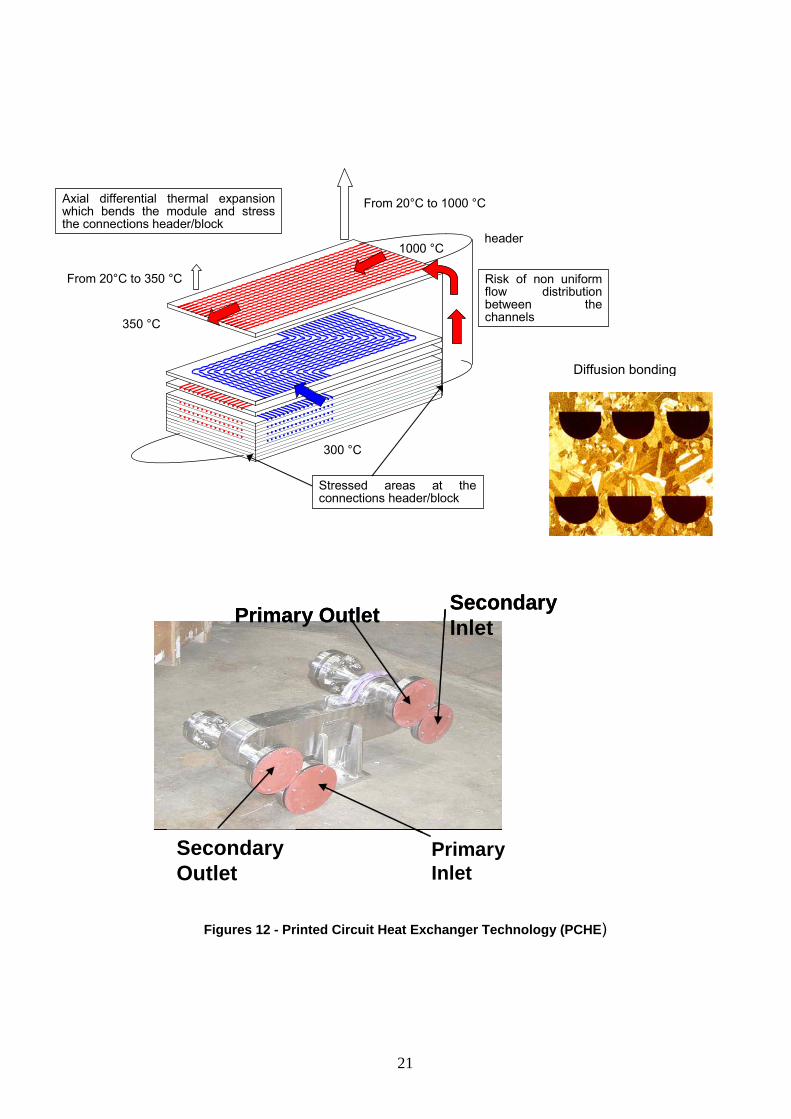
2.3.6 Intermediate Heat Exchanger (IHX) (VHTR, GFR crosscutting issue) The IHX for the GFR or VHTR system is the component in which the heat from the primary circuit helium (850 to 950 °C) is transferred to the secondary circuit helium (about 800 to 900 °C), thus keeping the secondary circuit free of radioactive contamination. The secondary fluid will be used for the heat transfer to a third circuit coupled to the unit of hydrogen production or to other process heat applications (Figure 1). The IHX will be located within a pressure vessel in the reactor containment. Therefore, the only pressure differential that the IHX will see during normal service is a relatively low pressure (a few bars). This significantly reduces long-term loading on the materials within the IHX. The performance to be achieved is a thermal effectiveness of at least 90% and low pressure drops (about 1 bar). Two advanced technologies : Printed Circuit Heat Exchangers (PCHE) and Plate Fin Heat Exchangers (PFHE) and one back up technology : helical tubes heat exchangers are suggested to be investigated in order to determine the technical feasibility limits of each concept. The printed circuit technology (PCHE) (Figure 12) is a compact, counter-flow heat exchanger design based on plate sheets into which fluid flow channels are chemically etched and assembled by diffusion bonding. The milled plates are then stacked into a solid block (size 130 x 56 x 60 cm). One module of IHX consists of eight blocks (130 x 56 x 480 cm). This technology is well mastered by some manufacturers. The plate fin technology (PFHE) (Figure 13) is based on very thin fins forming by stamping and assembled by brazing on flat foils. With a very small hydraulic diameter (around 1 mm) the same level of compactness, compared with PCHE can be achieved. These heat exchangers are significantly smaller in size than a standard shell and tube heat exchanger, due to the effective use of the heat transfer area. The main objective of the validation program of the block and headers design, and of the manufacturing processes at an industrial scale, is to select the material which can accommodate the very high temperature and suitable for chemical etching and diffusion bonding (PCHE) or stamping and brazing (PFHE). The helical tubular IHX (Figure 14) is considered as a feasible back-up solution. The main objective of the validation program is to select the material for very high temperature and to validate the optimised design to be proposed in order to limit the size of the IHX modules and optimise the compactness. The main items addressed by the IHX development program for the three concepts are :
- Design work based on fluid dynamics analysis (flow distribution of the IHX), creep/fatigue behaviour of connections between headers and heat core.
- Selection of materials (Nickel-Chromium alloys : Inconel 617 or Haynes 230 for near term
development or ODS PM 1000, PM 2000 for longer term applications) based on :
o The determination of manufacturing parameters (forming, channel machining or etching, assembly techniques, joints characterizations).
o The mechanical tests under vacuum and controlled atmosphere and the corrosion behaviour in the environment of the primary and secondary circuits.
- Tests of IHX small mock-ups, about 50 KW to 1 MW in order to validate the fabrication process
and the thermal and mechanical performances in helium or in air loops. Transient conditions will be performed simulating cold and hot shocks (-100°C/mn, -0.4 MPa/mn; 7°C/mn, -1MPa/s).
20
1000 °C
350 °C
300 °C
Risk of non uniform flow distributionbetween thechannels
header
Axial differential thermal expansion which bends the module and stress the connections header/block
From °C to 350 °C
From 20°C to 1000 °C
Stressed areas at the connections header/block
20
Secondary
InletPrimary Outlet
SecondaryOutlet
PrimaryInlet
SecondaryInletPrimary Outlet
SecondaryOutlet
PrimaryInlet
Figures 12 - Printed Circuit Heat Exchanger Technology
21
Diffusion bonding
(PCHE)

Figures 13 - Plate Fin Heat Exchanger Technology (PFHE)
SERRATED FINS
Before and after BRAZING
0.8 à 2.5 mm
3.53 à 9.63 mm
MODULE
PLATES/FINS Assembly
Figure 14 - Helical tubes technology
22

Table 6 - IHX Specifications (GFR/HTR conditions)
IHX specifications at condition of core outlet temperature 850°C
Primary (hot side) Secondary (cold side) Fluid Helium Mix 80 % N2 20 % He
in mass Flow rate (kg/s) 290 810 Inlet Temperature (°C) 450 406 Outlet Temperature (°C)
850 806
Inlet Pressure (MPa) 5 4.5 Effectiveness Maximum Primary Pressure Loss Maximum Secondary Pressure loss
90 % 2 % 4 %
2.3.7 Power Conversion System (VHTR, GFR crosscutting issue) The direct gas turbine cycle represents a long-term option to apply coolant temperatures even much beyond 1000°C (up to about 1200°C) and to improve efficiency of nuclear electricity generation. This approach will need either cooling of the high-temperature part of the turbine or new (ceramic) materials allowing for higher operational temperatures and sufficient lifetimes. The three most critical components in terms of elevated temperature service in the Power Conversion System (PCS) for the 950°C VHTR or the 850°C GFR are the inlet turbine shroud, the turbine disks and blades and the recuperator (Figure 15). Turbine inlet shroud : accepts the helium coolant exiting from the hot duct and directs it to the turbine inlet (Figure 16 a). A high-strength cast Ni-base alloy might be employed in this area such as Alloy 617 or it may be more desirable to go to a carbon-carbon composite. Turbine : The most critical components of the turbomachinery (Figure 16b) in a direct cycle are the first stages of the turbine disks. In order to achieve a high efficiency, it is recommended to limit the cooling of the turbine by cooling the first stages. Considering the disk, no commercial materials satisfy the specifications of this gas turbine (maintenance intervals of 60000 h, unusual impure helium environment, maximum temperature of the disk expected between 700 to 750°C, disk size of 1.5m). The materials selected should be evaluated for acceptability for their use at the higher temperature required (750°C). The current disk material selection is a wrought Ni-base alloy with addition of Cr, Mo, Ti and Al. As regards the blades, blade cooling should be considered if it is desirable to limit the temperatures to less than 900°C. The potential beneficial effects (e.g. lower blade temperatures) of applied coatings should also be examined. An assessment in terms of energy conversion efficiency has to be performed as a function of the maximum disc and blade temperatures. It is expected that usual materials such as directionally solidified superalloys or single crystals meet the specifications. The specific R&D data needed at this stage are the following :
- The materials of the disks and blades selected should be evaluated for their use at higher temperature. The disk material developed is a Nickel super alloys (Udimet 720). The fabricability of which has to be demonstrated for large size disks as well as the thermal stability, the fatigue, the fatigue crack growth and creep resistance of the Udimet 720 new grade.
- For the blades, the thermal properties and the corrosion behaviour of coatings will be examined (coated Directionally Solidified Ni superalloys).
23

Recuperator : The recuperator (Figure 17) is a modular counter-flow helium-to-helium heat exchanger with corrugated-plate heat exchange surfaces. Printed circuit or plate-fin type heat exchanger can also be favoured because of their size and high efficiency. The helium inlet temperature is ~500°C for the GFR and ~600°C for the VHTR. An austenitic 300 series stainless steel will probably be selected for all portions of the recuperator. Options include such steels as 316L and stabilized steels such as 321 and 347. Manufacture of the heat exchange surfaces of the recuperator requires very high quality 0.35 mm sheet material of size 2.8 m x 2.2 m. Sufficient R&D data should be available for design to confirm effectiveness (heat transfer coefficient, flow distribution), to assess the compatibility with the environment at both 500°C and 600°C including corrosion, creep and creep-fatigue tests.
Table 7 - Power conversion system operating conditions and candidate materials System Component Normal
Temp (°C)
Abnormal Temp (°C)
Pressure (MPa)
Fluence (n/cm2) (E>0.1 Mev)
Service time (yr)
Materials
VHTR
GFR
Turbine Inlet
Shroud
950°C
850°C
~1000°C < 350 h in 7
yrs
5 MPa
5.0x10¹³ n/cm2
7
Alloy 617 or C/C
composite
Ni-base alloys
VHTR
GFR
Turbine Disks and
Blades
950°C
850°C
~1000°C < 350 h in 7
yrs
5 MPa
5.0x10¹³ n/cm2
7
Ni-base alloy for disk and
coated DS Ni-base alloys or single crystals
for blades
VHTR
GFR
Recuperator
600°C
500°C
< 600°C
5 MPa
2.0x10¹⁵ n/cm2
60
300 Series SS
24

Figure 15 - Power Conversion System Figure 16 a - First stage turbine blades
Figure 17 - Recuperator unit Figure 16 b - Helium turbine plant
25

2.4 Materials for hydrogen production process The VHTR can produce hydrogen from only heat and water by using thermochemical water-splitting cycle or by High Temperature Electrolysis (HTE). Based on an international review of the thermo-chemical reactions, the iodine/sulphur cycle was selected as the most promising cycle in terms of overall efficiency and technical criteria. Regarding HTE, activities on materials for the development of anode and cathode catalysts, electrode layers, inter-connectors are still currently under definition. The objective is to obtain very soon the requirements to launch the R&D program for the development of this technology. The Iodine-Sulfur (I-S) process is composed of three main parts : - The formation from I2, H2O and SO2 in the Bunsen section of two acid mixtures : (H2SO4+4H2O) and
(2HI+10H2O+9I2). Excess of I2 and H2O is necessary to achieve the two phases separation. The running conditions correspond to an about 125°C temperature and a 2-3 bars pressure. In this section, are involved concentrated acids at concentration up to 9 and 6 mol L-1 for respectively H2SO4 and HI. In such conditions, the main type of corrosion induced by these media is a generalized corrosion. Moreover, corrosion by HIx (HI/I2/H2O) phase could also proceed by pitting.
- The hydrogen production from HIx coming from Bunsen section by HI decomposition. In this part of the
process, the temperature and pressure reach respectively about 300°C and up to 50 bars. The residual water in the HIx phase is a significant parameter for the material corrosion.
- The decomposition of H2SO4 for the regeneration of SO2. In this section the media encountered by the
materials evolve from the very concentrated H2SO4 up to gas mixture (SO2, SO3, O2) at high temperature (850°C-900°C).
The running conditions in such a process are severe and various. Regarding materials studies, the compatibility of materials with the different media is the only R&D activity which is considered up to now. Corrosion tests are then conducted to assess the maximum temperature and acidity acceptable conditions, the long term behaviour and the corrosion mechanisms. Electrochemical and dipping tests have been selected to test all the acid conditions of the I/S cycle. In the following table are gathered the materials which can be considered for different part of the process.
26

Table 8 - Materials for the Iodine-Sulfur Hydrogen Production Process and Operating Conditions
for the Corrosion Experimental Program
System Component Normal Temp (°C)
Pressure (bar)
Materials Corrosion environment
Qualification requirements
I/S Bunsen section 130 2-3 Ta, glass coated steels, polymer
fluorocarbon elastomer or
plastic, ceramics, carbon
H2SO4, HI/H2O/I2 Validation test in representative environment
HIX distillation 300 Up to 50 Ta, Nb,glass ceramics
HI/H2O/I2, I2 Long term test in representative
conditions
H2SO4 decomposition/concentration
100-200 Less than a few bars
Glass, graphite, hastelloy, high Si
steels
H2SO4 55-80wt% Exposition in representative environment
H2SO4 decomposition/
partial
200-600°C
Less than a few bars
High Si steels, SiC H2SO4, H2O, SO3
Exposition in representative environment
H2SO4 decomposition
600-850 Less than a few bars
Fe6Ni-Cr with high Cr content
SO3, H2O, SO2, O2
Exposition in representative environment
2.5 R&D program schedule The research program on ‘Materials and components’ which has been launched since 2001, is expected to support both the Generation IV advanced gas cooled reactors systems (VHTR, GFR). The selected materials will have to meet the requirements of all the components and subsystems described in this report. The validation of candidate materials is scheduled for 2008. The development of optimised materials and the qualification program is targeted for 2012.
27

3. GAS FAST REACTORS SYSTEM : SPECIFIC REQUIREMENTS FOR MATERIALS OF THE CORE 3.1 Introduction Resulting from preliminary design studies of different powers of GFR ranging from a few hundred MWe up to about the EFR’s power (Figure 18), the CEA is presently focusing on a 1200 MWe reference reactor whose main characteristics are listed in Table 9.
Figure 18 - Layouts of two starting GFR designs referring to two different size and powers : respectively 300 and 1200 MWe for the left and right images. As far as specificities of GFR are considered, the main challenge is that the core structural materials will have to withstand important fast neutron fluences, higher than 100 dpa, and high operating temperatures, 1000°C in normal conditions and up to 1600 °C in accidental conditions. 3.2 The common base of technology for the gas-cooled systems Even if GFR design could differ from VHTR one (see Figure 19 which gives an example of upflow GFR core different from the standard downflow design classically used for thermal reactors), the technology base for the out-of-core components of the GFR, vessel and in-vessel structures as well as the out-of-reactor block components for energy production or conversion, is considered as being common with the corresponding HTR/VHTR technology (see N° 2.2, 2.3.2, 2.3.4, 2.3.5, 2.3.6, 2.3.7 described in the previous section).
28

Figure 19 - Example of design of a GFR boiler
29

Before describing in detail the technology gap for the core components of the GFR, a rapid overview of the requirements for the out-of-core components which are similar to the corresponding structures planned for the HTR/VHTR gas-cooled systems is summarized. The out-of-core GFR’s structures, their operating conditions and target properties as well as the corresponding candidate materials are listed in Table 9 below :
- Primary circuit (Figure 19) and internal structures (useful life, > 400000 h) :
o Core support barrel and gas duct barrel that are large cylindrical structures around the core allowing to maintain the radial stability of the core and to carry He.
o Hot gas duct carrying hot He toward the power conversion system and the SCS (Shutdown Cooling System).
o Cross vessel carrying cold He toward the core. o Other in-vessel structures as core support components or upper plenum shroud. o Operating conditions : temperature range 490 < T < 850 °C, with low irradiation damage
(<< 1 dpa), significant mechanical ( 10 – 80 MPa) and thermal stresses (high values in coatings).
o Desired properties : fabricability, coating and welding capabilities, mechanical strength, creep, fatigue and toughness adequate properties, good compatibility with He impurities.
o Candidate materials : coated or uncoated (depending on operating temperature & material) conventional materials (9Cr or austenitic steel) optimized Ni or Fe/Cr/Ni bases alloys and advanced Ni/Cr/W bases.
- Reactor vessel (useful life, > 400000 h) :
o Pressurized component operating at 440 °C and 80 bar in normal conditions, 550 °C in reference off-normal transient, receiving very low irradiation damage (~ 0.005 dpa).
o Fabricability, and welding capabilities on thick products (> 180 mm), mechanical strength, creep, fatigue and toughness adequate properties, good compatibility with He impurities.
o Candidate materials : conventional or creep optimized 9Cr martensitic steel.
- Turbine main components (useful life, 60000 h) : disk and blades
o High temperature (850 °C), high mechanical stresses (~ 225 – 266 MPa), low corrosion by He impurities.
o Fabricability in large product (disk diameter, 1600 mm), mechanical strength, creep, fatigue adequate properties, good compatibility with He impurities.
o Candidate materials : conventional and advanced Ni base superalloys. 3.3 The fuel concepts Having completed a preliminary evaluation-screening phase of the different fuel technologies (Figure 20), the CEA R & D is presently focusing on two main concepts : dispersion and solid solution fuels which are compared in the Table 9. 3.3.1 The dispersion fuel concept : The dispersion fuel concept offers a solution for minimizing irradiation-induced property changes in fuel materials by localizing fission damage into a small area around the fissile inclusions. In this concept, fuel is a bi-phased material or a so-called Inert Matrix Fuel (IMF) with a fissile phase and an inert matrix support with a typical ratio of 70/30 or 50/50 in volume. The composite fuel most likely to be adapted to GFR is a particles or sticks embedded in an inert matrix. In the plate concept chosen today (Figure 21) the fuel, the pellets of (U, Pu)C (in red in Figure 21), is contained in an honeycomb SiC structure hermetically closed by two cladding plates to allow the tightness of the fuel element. In this concept, each alveolus realizes the confinement function and a metallic liner could be considered later to improve the leak tightness. The inert matrix is a support with a thermo-mechanical role : heat transfer and mechanical structure keeping; the other role is to keep all fission products up to ~1600°C during depressurisation condition.
30

Figure 20 - Main fuel concepts evaluated up to now. Among them, only the dispersion fuel (plate)
and the solid solution (pin) have been selected for further investigations.
31

Table 9 - Design and material characteristics of the reference GFR and their both fuel concepts
Reactor, fuel & materials characteristics
Dispersion fuel : plate & hexagonal can concept
Solid solution fuel : pin & hexagonal can concept
Common characteristics - Thermal power (MWth) - Power density (MWth/m3) - Core dimension (cm) - Numb. of fuel – absorbing – inert - reflector subassemblies - Inlet/outlet He temperatures
2400 100
Radius = 222 & Height = 155 82 (12 rows) – 33 – 1 - 48
488/850°C
Core & fuel characteristics - Composition (Volume fraction) - Mass of Pu + M.A. (t/GWe) - Burn-up av/max (at %) - Dose av/max (dpaSiC) - Max fluence (E27 n.m-2) - SA duration (average BU)
40% fuel (= 22.4% (U/Pu)C + 6.4%
matrix (SiC) + 11.2% clearance) 40% He
20% structural materials 7.7 (initial) 10.1/14.7 112/163
2.5 (n > 0.1 MeV) 3 x 831 = 2493 EFPD
20.6% (U/Pu)C
58.6% He
20.8% structural materials 7.2 (initial) 10.1/13.1 119/154
2.3 (n > 0.1 MeV) 3 x 766 = 2298 EFPD
Inert & structural materials - Inert material : > reference > function > operating conditions > critical in-service properties & behavior - Structural materials > reference > function > operating conditions > critical properties
SiC
Casing of the fuel dispersion & first containment of FP
Irradiation damage via recoil of FP
and neutron displacements. T = 1200°C -> 1650°C(accident)
FP & He confinement under normal &
accid. (depressurization) Chemical interaction between fissile &
inert phases or structures
SiCf/SiC, improved composites (Cermet) or refractory Nb-Zr-C
metallic alloy as back-up solution
1) IMF casing via cladding plates 2) hexagonal canning of plates
Highly neutron irradiated at 500 <~ T <~ 1000°C
-> 1600°C (accidental conditions)
Irradiation-induced swelling, creep & embrittlement, thermal creep, impact
& toughness properties, corrosion resistance to impure He & chemical
compatibility with fuel
Unfounded
Ditto plate concept
1) Casing of the fuel pellets & first barrier for radioactive products
dissemination 2) hexagonal canning of the pins
Ditto plate concept
Ditto plate concept
In order to perform these challenging objectives, microstructure is adapted to reduce the effect of damage : fissile phase have a typical diameter of several hundred micrometers and minimum distance between two fissile inclusion is more much higher than twice Fission Product recoil range (i.e. 8-12 µm).
32

Figure 21 : Plate concept showing fuel in red and in grey, the alveolar inert casing and the upper
cladding plate (here open to see the interior) Main questions concerning this concept remain and are listed below :
- Behaviour under high temperature, high fissile inclusion density.
- Fission products and helium (from minor actinides) confinement under high temperature gradient,
RIA or depressurisation.
- Chemical interaction between fissile compound and inert matrices or structure.
- Another material may be useful to prevent gas release : coating close to inclusions or for the fuel
element (plate).
- Partitioning matrix from fissile phase.
- Fabrication process for fissile phase homogeneity.
3.3.2 The solid solution fuel concept : The main idea is to use a standard concept for fuel element : pin with fuel pellet. Pellets are made with a solid solution of (U, Pu, M.A.)N or (U, Pu, M.A.)C or even (U, Pu, M.A.)O2. But questions remain on material structures for the cladding that will be submitted to fast neutron fluence and high temperature (~ 500-1000°C). Stainless steels, developed for sodium cooled fast reactor, are not relevant and now we have to find ceramic materials, refractory alloys or both (Cermet) to enhance high-temperature behavior.
33

The following figure (Figure 22) describes the fuel subassemblies obtained with both previous concepts.
Figure 22 - Example of plate and pin subassemblies designed for the 1200 MWe reference GFR
3.4 Structural materials of in-core applications The main in-core applications aimed here are the following structural components involved in the different fuel concepts :
- Cladding plates and hexagonal cans for the composite fuel concept. - Cladding tubes and wrapper tubes for the solid solution fuel concept. - Others subassembly structures to maintain the fuel elements inside the wrapper and to keep a
finite clearance between to allow their best cooling. - Subassembly structures for fast neutrons reflectors.
The operating conditions of these components (Table 9) are presently only roughly known :
- Temperatures between about 490 and 1000°C in normal operation, but up to 1600 °C in case of loss of coolant with depressurization accident.
- Level of damage similar to that planned in EFR core : higher than 150 dpa.
34

- Important fuel subassembly duration : between 2300 & 2500 EFPD. - Mechanical stresses probably low but diversified in nature (pressure, tension, fatigue, impact). - Environmental conditions via corrosion, at high temperature and under irradiation, by He
impurities.
In the field of nuclear materials, it is hence a new important challenge to find a structural material having the following conflicting properties :
- Fabricability in the final form and welding capabilities. - Initial & in-pile compatibility with He (and impurities) and actinide compound. - Physical, neutronic, thermal, He or gaseous fission products permeability, tensile, creep, fatigue
and toughness adequate property : initial characteristics and assessment of their degradation under high neutron flux and dose.
- Microstructure and phase stability under irradiation. - Irradiation creep, in-pile creep and swelling properties.
CEA material studies will be made preferentially on the most promising ceramic solutions to be chosen among carbides (preferred option) SiC and SiCfiber/SiC, ZrC and related composites, TiC, NbC, or other materials like nitrides (TiN, ZrN), oxides (MgO, Zr(Y)O2). The effort will also include inter-metallic compounds like Zr3Si2 as a promising candidate of fast neutron reflector. As monolithic microstructured ceramics are well known to be brittle, important work will be carried out on the following solutions :
- Nanostructured carbides ceramics SiC, then ZrC.
- SiC Fiber reinforced SiC, then ZrC matrix.
- Ceramic fiber reinforced ceramic & refractory metallic matrix.
- Cermet : Multi coated, interpenetrating skeletons or dispersed Cermet materials where V, Cr, Nb or Mo could be the metallic part of the Cermet option.
3.5 Summary of main R&D objectives The main R & D goals are listed below :
- In the selection phase ranging up to 2006, to perform screening tests of irradiation and fabrication to focus toward a reference fuel element and corresponding structural materials.
- In the second phase of knowledge acquisition on these reference solutions, up to about 2010, to assess the in-service behavior of the different materials via out-of-pile characterization and modeling works, simulations by charged particles and material test reactor experimentations.
- Both these objectives will be reached via the implementation of two experimental irradiations in Phénix, taking advantage of the end-of-life of the reactor. These irradiations, respectively FUTURIX-MI and MATRIX, will be conducted at high (between 800 and 1000°C) and low temperatures (between 400 and 530°C) to investigate the extreme parts of the operating temperature range.
35

4. SODIUM FAST REACTORS SYSTEMS : REQUIREMENTS FOR STRUCTURAL MATERIALS 4.1 Introduction From the past international experience on sodium-cooled Fast Reactors (FR) systems and considering the different reactors presently used in the world, we can distinguish two existing designs : the loop- and pool-type designs. In the “loop” technology, the primary sodium exits the vessel which contains the core and feeds, through primary pipes and external intermediate heat exchangers (Figure 23).
Figure 23 - Layout of a loop-type SFR
It is the design used for instance for Rapsodie, SNR-300, Joyo and Monju. From this design, JNC and the electric utilities in Japan propose, for the next future, an advanced project called JSFR. This technology offers a large compactness of the vessel and in-vessel components (Figure 24) and allows a separation between the reactor block and the exchanger devices, but present some drawbacks as a potential larger irradiation damage on the main vessel and the presence of radioactive sodium outside the reactor block.
36

Figure 24 - Reactor block of JSFR
In the «pool» design, all of the primary sodium stays in the primary vessel which contains the core because intermediary heat exchangers and primary sodium pumps immerse themselves in this large diameter main vessel (Figure 25).
Figure 25 - Layout of a pool-type SFR
37

This design was used for the already built plants Phénix, Superphénix, PFR, BN-600, and in the EFR project. In the following, we will take the EFR project (Figure 26) as representative of the present reference SFR technology.
Figure 26 - EFR reactor block showing the main In-vessel components. 4.2 Overview of the main critical components Regarding the critical components of the SFR systems, the main challenges are basically the following :
- Core structures withstanding important fast neutron fluences at normal operating temperatures up to 700°C.
- In-vessel structures operating at temperatures ranging from 390 up to 550°C in a low neutron flux
environment prone to induce embrittlement due to atomic displacements and/or He generation.
- Primary and secondary circuits as well as steam generator tubing exhibiting numerous welded junctions that must operate in a high temperature domain.
Table 10 compares, for each critical component of a given SFR design, the materials already chosen or in project and their operating conditions.
38

Table 10 - Structural materials & operating conditions of two main SFR technologies
Main Components & critical characteristics
EFR pool design (1500 MWe)
JSFR loop design (1500 MWe)
Fuel subassemblies - Mechanical integrity of the first barrier (clad) & SA (wrapper) - All types of loading - Irradiation-induced swelling, creep & embrittlement - Thermal creep - Fuel clad interaction - Impact & toughness properties
Materials for Cladding tubes and hexagonal cans, to be chosen among (French strategy) :
- Optimized austenitic steels : AIM1, advanced low Cr / high Ni - Optimized ferritic/martensitic steels : EM10, T91, new 9-12Cr - ODS ferritic/martensitic steels : standard or new ODS 9-12Cr
Operating conditions : - Normal temperature : between 390 & 700°C - Accidental transient : up to 850°C, several hours - Minimal displacement dose ~ 160 dpa (Target ~ 200 dpa) - Minimal burn-up : 150 GWd/t
Below core structures - Mechanical integrity of the core - Thermal & dynamic loadings - Degradation of the toughness under irradiation
Material for core support structures (diagrid components) :
- 316LN for the upper & lower plates of diagrid separated by spacers bars
Operating conditions : - Temperature : ~ 390 – 400°C - Dose : ~ 1 dpa - Duration : 40 years
Above core structures - Mechanical integrity of the reactor - He production & thermal loadings - GB embrittlement - Mechanical & thermal fatigue
Materials for grid plate, thermal shield, above core plug :
- 316LN for the grid and plug - Ni base alloy for the shield
Operating conditions : - Temperature : ~ 550°C - Dose : ~ < 1 dpa, 1 appm He - Duration : < 40 years
Under investigation
Main vessel - Long term mechanical integrity of the second barrier
Material for forged rings (diameter ~ 20 m, thickness ~ 50 mm) :
- 316LN Operating conditions :
- Temperature : ~ 400°C - Dose : ~ < 1 dpa - Duration : 40 years
Higher : - compactness (diameter ~
10 m, thickness ~ 30 mm) - irradiation exposures - temperatures
Primary & secondary circuits; steam generator tubes - Mechanical integrity of welded tubes - Thermal & mechanical loadings - Reheat cracking of welded junctions
Material for tubes : - Standard austenitic steels from
the 300 series as present reference
- 9Cr 1Mo or advanced 12Cr ferritic/martensitic steel as new candidate.
Operating conditions : - Primary Na temperature : 390
– 550°C - Secondary Na temperature :
330 – 520°C
Material for tubes : - New 12Cr ferr./martensitic
steel like HCM12A (T122) Operating conditions :
- Primary sodium temperature : 395 – 550°C
- Secondary sodium temperature : 335 – 520°C
39

4.3 Core structures materials
In the following it will be focused on the main components of the fast fuel subassembly, fuel pins and hexagonal wrappers (see Figure 27), that operate in the most severe conditions.
Figure 27 - Fuel subassembly of Superphénix.
The normal operating temperatures of the fuel cladding range from 390 to 650°C, 700°C in hot spot conditions. In accidental conditions core components must withstand temperature as high as 850°C during several hours. Regarding the French Fast Reactor, the standard subassembly (SA) is fabricated with an austenitic steel (a special grade of 15/15Ti) for the fuel cladding and with a 9Cr-1Mo martensitic steel (EM10) for the wrapper. Due to a limited swelling resistance of the cladding tube material, the maximal dose reached by a standard SA must be limited today to about 100 dpa, which is very low considering the potential use of the fuel pellets inside the pins and thus quite far from the target doses (160 – 200 dpa) expected to reach the economic viability of the future Fast Reactor. To extend the duration of the SA(s) and thus to improve the behavior of the structural materials under irradiation, three main replacement solutions are proposed for the fuel cladding :
- Taking into account that the AIM1 grade which is the best specification of 15/15Ti is probably limited to about 130 dpa (the irradiation of several Phénix SA(s) is still in progress but presently no PIE is available to validate this option), it is proposed to explore the advanced austenitic way (12-15Cr/20-25Ni) to expect reaching the first target of 160 dpa with a mature austenitic steel.
- If the design will lead to lower the cladding temperature, another mature way could be found with a new grade of ferritic/martensitic steel (similar to T92) optimized with regard to their mechanical properties at high temperature.
40

- Finally, the third long term and very challenging option which is explored by the Japanese team is the ODS ferritic/martensitic (F/M) that should combine the excellent swelling resistance of all F/M steels with a good mechanical strength at high temperature due to the oxide dispersion strengthening (ODS).
Therefore, it can be concluded that an important effort of R&D remains to be done to validate and qualify an optimized ODS F/M steel as structural material for Fast Reactor core applications. 4.4 Internal structure and sodium circuits The term of internals structures refers to vessel and in-vessel components situated outside the core. In general these structures are permanent or quasi permanent and their design life is equal to that of the reactor that is to say, 40 years. They are almost fabricated with austenitic steel plates of the series 300 grades (mainly 304 & 316) and are assembled using weld metals as 308, 16-8-2 or 19-12-2. The Below Core Structures (BCS) described in Figure 28, the diagrid and core support components, are exposed to cold sodium (390 – 400°C) and to displacement doses close to about 1 dpa.
Figure 28 - BCS of Superphénix The upper part of the diagrid is probably the most critical because it is the closest structure to the core and it directly support the fuel SA(s). Like the other BCS, it is subjected to thermal stresses, vibrations and accidental dynamic loadings. Thus the main cause of concern is degradation of its fracture toughness under long term irradiation.
41

The Above Core Structures (ACS) described in Figure 29, particularly the grid plate, the thermal shield and the ACS plug, are exposed to the hot sodium (550°C) flowing out of the core and to a neutron flux (dose lower than 1 dpa producing He at about 1 ppm).
Figure 29 - ACS of Superphénix The most critical structure is the lower plate of the above core plug. This structure is subjected at high temperature (550°C) and continuous stresses due to thermal differential expansions (inducing creep), reactor shutdown or start-up cycles (inducing fatigue and creep-fatigue) and thermal striping. Moreover all ACS are subjected, via He production and segregation phenomena under irradiation, to irradiation-induced grain boundary embrittlement and thus, to a degradation of the creep and creep-fatigue properties. Regarding primary and secondary circuits as well as the tubing of steam generator, the main concern is the mechanical integrity of the welded junctions which are known to be subjected to in-service cracking. Being presently fabricated with austenitic steels of 300 series, the design and life duration of these components could be notably improved by adopting new grade of 9-12Cr F/M steel that nevertheless, remain to be specified, validated and qualified. 4.5 Summary of main R&D objectives The main R & D goals are recapitulated below : Core materials
- To validate the behavior of the AIM1 standard cladding material to the maximal dose of 130 dpa via post irradiation examinations by 2009 of one or two subassemblies presently in use in Phénix
42

or via the implementation of an experiment in an other foreign reactor open to the international collaboration (Monju?).
- To explore the possibilities of the advanced austenitics in a large range of specifications via the exploitation of the experiment SUPERNOVA presently at the end of its irradiation in Phénix.
- To develop and validate under irradiation the ferritic-martensitic ODS way for the cladding and the martensitic T92-type way for the wrapper.
BCS & ACS structures
- To elaborate and implement an R&D plan to evaluate the end-of-life damage of the corresponding structures of Phénix via their dismantling, sampling and examinations after the reactor shutdown.
Sodium circuits
- To develop and validate a new high strength 9/12Cr ferritic-martensitic steel to lower the volume of tubing and to improve the performances of the exchangers compare to the previous austenitic references for these structures.
5. Conclusion In order to provide the essential R&D results needed to support the materials selection and qualification activities for both the reactor and balance of plant components of the Generation IV systems described hereabove, a research and development plan has been launched since 2001 in CEA. Furthermore, the CEA teams are involved in a joint collaboration with their partners Framatome-ANP and EDF to meet the objectives of the R&D plan. Beyond the partnership with the French industrials, CEA is also involved in the Generation IV international forum, bilateral cooperations with USA, Japan and Russia and in the European R&D framework program which offer an opportunity to share our means to develop ‘Materials and Components’ for the SFR, GFR and VHTR systems. On the basis of the characterization of materials (microstructural evolution, mechanical behaviour, corrosion resistance, irradiation effect) in relevant service and abnormal conditions, the assessment and evaluation of selected materials, joining process and design are carried out for the following reactor sub systems and components :
- The reactor pressure vessel. - The high temperature metallic core internals, the hot duct and the IHX. - The turbine materials. - The very high temperature graphite used for the reflectors and support structures in the core
region. - The very high temperature control rod cladding and/or guide tube components using
carbon/carbon or SiC/SiC composite materials. - The reactor pressure vessel and hot duct insulation.
Finally, the qualification of selected designs, structural materials, and joining processes will need to be supported by :
- Standard tests methods and codification of very-high-temperature mechanical design rules. - Specification and development of test loops and other experimental facilities, such as :
• Dedicated test benches (corrosion, creep-fatigue facility under environment, tribology, tightness, thermal barriers, purification, etc).
• Helium test loops for medium-size components. • Irradiation test facilities for the qualification of components in the representative
conditions of the future systems.
43

44