materials for mw sized aerogenerators part 2. materials characteristics
TRANSCRIPT
L.M. Wyatt Engineering Materials Consultant
The requirements of the optimum three materials for wind turbine blades are described
Furling GLOSSARY Coning Fixing blades at an angle not a right angle to
the shaft so that when rotating they generate a cone with its apex pointing upwind.
Free Coning Hinging the blades individually on the shaft so that they are free to assume an angular position which aligns each blade in a direction coinciding with the resultant wind and centri- fugal force.
Feathering Variation of pitch of blades to vary reaction with wind.
Hawt Vawt Pitch Angle
Yaw
A<Jol
Movement of rotor to reduce wind resistance of blade assembly. Horizontal Axis Wind Turbine. Vertical Axis Wind Turbine. Angle betwen chord of blade and direction of Rotation. Rotation of rotor, shaft and (usually) power train about vertical axis to align rotor axis with, (or sometimes away from) wind direction.
Steel Steel combines the advantages of a
high elastic modulus and a high yield strength which together resist buckling, a high fatigue strength and ready availability. Its drawbacks are a high density which magnifies gravity or inertia generated fatigue stresses, the possibility that welds may contain damaging defects and uncertainties in the effect of environment.
The requirement to resist cyclic bending moments in horizontal axis and straight bladed vertical axis machines necessitates sophisticated design to minimise stresses and almost immaculate fabrication to limit the size of defects and the magnitude of locked in stresses.
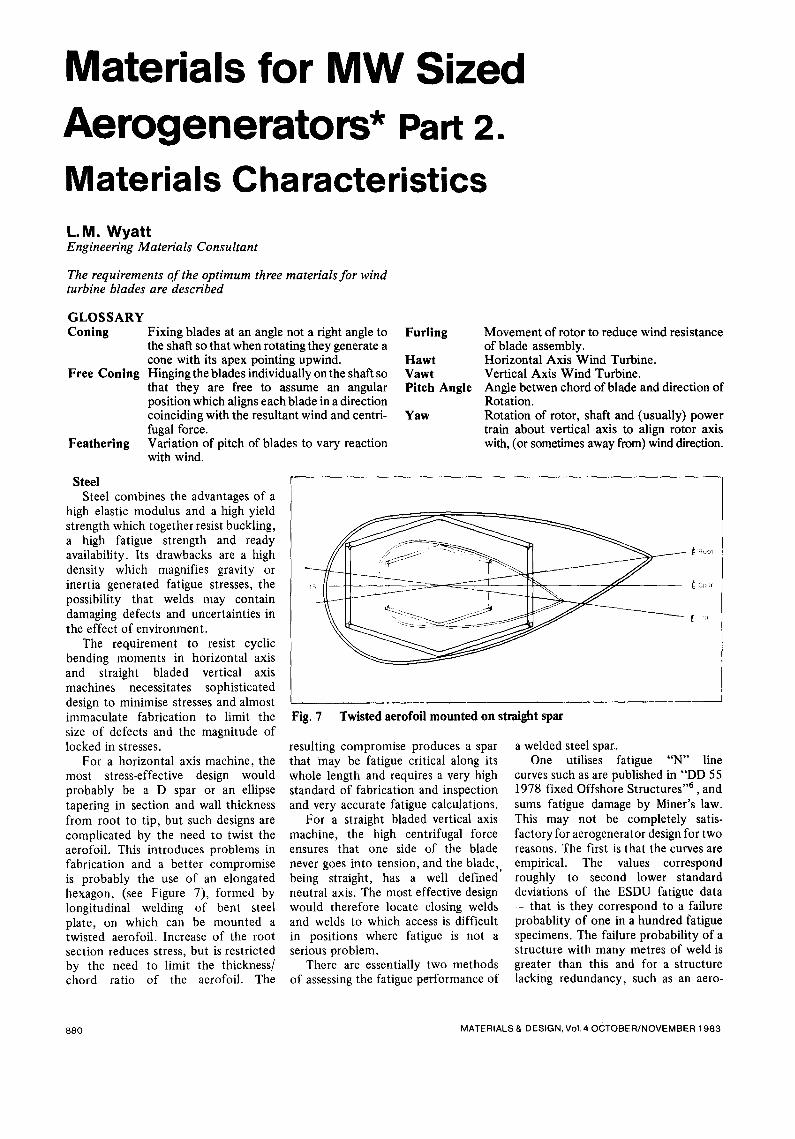
For a horizontal axis machine, the most stress-effective design would probably be a D spar or an ellipse tapering in section and wall thickness from root to tip, but such designs are complicated by the need to twist the aerofoil. This introduces problems in fabrication and a better compromise is probably the use of an elongated hexagon, (see Figure 7), formed by longitudinal welding of bent steel plate, on which can be mounted a twisted aerofoil. Increase of the root section reduces stress, but is restricted by the need to limit the thickness/ chord ratio of the aerofoil. The
Materials for MW Sized Aerogenerators* Part 2.
Materials Characteristics
Fig. 7 Twisted aerofoil mounted on straight spar
resulting compromise produces a spar that may be fatigue critical along its whole length and requires a very high standard of fabrication and inspection and very accurate fatigue calculations.
For a straight bladed vertical axis machine, the high centrifugal force ensures that one side of the blade never goes into tension, and the blade, being straight, has a well defined neutral axis. The most effective design would therefore locate closing welds and welds to which access is difficult in positions where fatigue is not a serious problem.
There are essentially two methods of assessing the fatigue performance of
a welded steel spar. One utilises fatigue "N" line
curves such as are published in "DD 55 1978 fixed Offshore Structures ''6 , and sums fatigue damage by Miner's law. This may not be completely satis- factory for aerogenerator design for two reasons. The first is that the curves are empirical. The values correspond roughly to second lower standard deviations of the ESDU fatigue data - that is they correspond to a failure probablity of one in a hundred fatigue specimens. The failure probability of a structure with many metres of weld is greater than this and for a structure lacking redundancy, such as an aero-
880 MATERIALS & DESIGN, Vol. 40(~TOBER/NOVEMBER 1983
generator blade spar, it would be wiser to take the third lower standard devi- ation. Secondly, this design procedure assumes that locked tensile stresses at the toe of the weld (where failure usually starts) are such that the stress cycle i~ always in tension. It is not clear that it would be possible to guarantee the fatigue performance of a steel aerogenerator spar under these conditions for thirty years.
The second method of assessing fatigue performance, giving a greatly improved certainty of performance, is fatigue crack growth calculation. After welding surface dressing and stress relieving the welds in all highly stressed positions are inspected to reveal the size and position of the largest defects. A limiting value for the life of the com- ponent can then be determined by calculating crack growth rates.
It should be possible by modern techniques to weld material such as BS 4360:1979, Grade 50 D to a maximum defect size of 1.25mm on the surface or 2.5mm internal. Boeing claim to be able to weld a twisted "D" spar to this standard. This, combined with good design should ensure that the stress intensities which cycle at rotational stresses are below the crack growth initiation level at the commencement of life. At later stages during the life of the comp- onent, start-up, shut-down and maxi- mum gust stresses which occur at much lower frequency will have lengthened the crack so that crack growth occurs even at the lower cyclic stresses.
The resulting crack growth cal- culation is complex but even so Boeing have devised a procedure which they have verified, experi- mentally, which supports their claim that a twisted "D" spar which they have manufactured should have a minimum life of 30 years.
Effect of Offshore Environment on Steel
The procedure outlined above refers to fatigue behaviour in air. The high humidity and salt spray to which aerogenerator components will be subjected in an offshore environment may adversely affect fatigue perform- ance but no immediately relevant investigations have been carried out. However drawing on other studies of steel in marine environments the conclusion can be drawn is that unless design, fabrication and inspection can
keep the stress intensity at the tip of a defeat to below the level of initi- ation or until information on the effect of salt spray atmospheres on fatigue crack growth becomes available, steel strength members in aerogenerator blades operating offshore must be protected. It may be possible to do this, using a zinc epoxy or zinc silicate coat on the spar and covering it completely with a fibre glass aerofoil. The effect of salt spray atmospheres on the fatigue crack growth in constructional steel requires to be evaluated to underwrite design and to make it possible to assess the effect of defects in the protection.
GFRP GFRP has advantages of low density,
high resistance to tensile and alternating stresses, resistance to environment and ready availability. These properties make it an optimum material for use as an aerofoil and it is used for the strength member of a number of horizontal axis designs.
The main problem for horizontal axis and for straight bladed vertical axis machines is the low modulus which results in very large deflections and renders it very difficult to design to withstand buckling under large wind forces (for horizontal axis aero- generators) and large centrifugal forces (for straight bladed vertical axis aero- generators). The requirement to avoid buckling effectively imposes a limiting design strain of 0.2%. This is, where possible, achieved by optimising the orientation of the fibre reinforcement.
Spars or complete aerofoils may be manufactured by filament winding, by pre-impregnated tape winding or by hand lay up. Winding procedures require very large rotating machinery. Filament winding can be used to in- corporate very long fibres, but it is difficult to lay fibres at an angle close to the axis. Tape winding can lay fibres of any required orientation but the fibre length is limited by the width of the tape. Optimal properties can be obtained by a combination of the two.
A typical load bearing member would have about 70% of the filaments orientated axially, 10% hoop and 20% at + 45 °.
Hand lay up permits the incorpor- ation of fibres running the whole length of the blade. However, hand layup requires a longitudinal joint the complete length of the blade and it is
essential to ensure that this lies on the neutral axis.
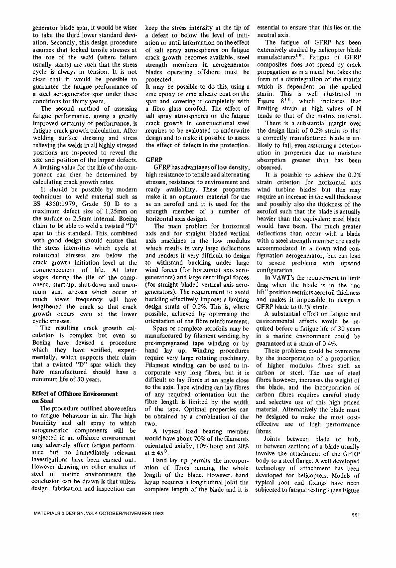
The fatigue of GFRP has been extensively studied by helicopter blade manufacturers lo Fatigue of GFRP composites does not spread by crack propagation as in a metal but takes the form of a disintegration of the matrix which is dependent on the applied starin. This is well illustrated in Figure 811, which indicates that limiting strain at high values of N tends to that of the matrix material.
There is a substantial margin over the design limit of 0.2% strain so that a correctly manufactured blade is un- likely to fail, even assuming a deterior- ation in properties due to moisture absorption greater than has been observed.
It is possible to achieve the 0.2% strain criterion for horizontal axis wind turbine blades but this may require an increase in the wall thickness and possibly also the thickness of the aerofoil such that the blade is actually heavier than the equivalent steel blade would have been. The much greater deflections than occur with a blade with a steel strength member are easily accommodated in a down wind con- figuration aerogenerator, but can lead to severe problems with upwind configuration.
In VAWT's the requirement to limit drag when the blade is in the "no lift" position restricts aerofoil thickness and makes it impossible to design a GFRP blade to 0.2% strain.
A substantial effort on fatigue and environmental affects would be re- quired before a fatigue life of 30 years in a marine environment could be guaranteed at a strain of 0.4%.
These problems could be overcome by the incorporation of a proportion of higher modulus fibres such as carbon or steel. The use of steel fibres however, increases the weight of the blade, and the incorporation of carbon fibres requires careful study and selective use of this high priced material. Alternatively the blade must be designed to make the most cost- effective use of high performance fibres.
Joints between blade or hub, or between sections of a blade usually involve the attachment of the GFRP body to a steel flange. A well developed technology of attachment has been developed for helicopters. Models of typical root end fixings have been subjected to fatigue testing3 (see Figure
MATERIALS & DESIGN, Vol. 4 OCTOBER/NOVEMBER 1983 881
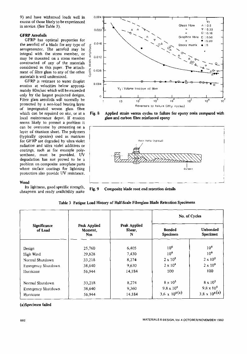
9) and have withstood loads well in excess of those likely to be experienced in service. (See Table 3).
GFRP Aerofoils GFRP has optimal properties for
the aerofoil of a blade for any type of aerogenerator. The aerofoil may be integral with the stress member, or may be mounted on a stress member constructed of any of the materials considered in this paper. The attach- ment of fibre glass to any of the other materials is well understood.
GFRP is resistant to water droplet erosion at velocities below approxi- mately 80m/sec which will be exceeded only by the largest projected designs. Fibre glass aerofoils will normally be protected by a non-load bearing layer of impregnated woven glass fibre which can be repaired on site, or at a local maintenance depot. If erosion seems likely to present a problem it can be overcome by cementing on a layer of titanium sheet. The polymers (typically epoxies) used as matrices for GFRP are degraded by ultra violet radiation and ultra violet additives or coatings, such as for example poly- urethane, must be provided. UV degradation has not proved to be a problem on composite aeroplane parts where surface coatings for lightning protection also provide UV resistance.
Wood Its lightness, good specific strength,
cheapness and ready availability make
0.024
0.020
o~ 0.016
E 0.012
0.008
O
0.004
Fig. 8
Fig. 9
I . . . , . . . I 1 I I 1 Vf
' ~ ~ ~ Glass f ibre A : 0.5 -- a A . ; 0 3 3 \ -.-. % \ ,, ,, . _
~ "~. ~ , O : 0.16 -- ~ ~ A ~ Graphite f ibre [] :0 .50 -
~ v . " • : 0.33
-- ~ . ~ " ~ A ~ r q ~ Epoxy matrix • :0 -- _ ~ . ~ c~ ~ • _
- - ~ ~ A 9",.. - -
- ~ - " ~ ' - ~ ~-._-
- - • A 7 ~"- . - -
[] [] C ~ r'l =_m i r ' l u ..-
Vf : Volume f rac t ion of fibre
I I I I I 10 102 103 104 105
: c :, ~--a--6-- °
I 10 6 10 7
Reversals to fai lure (2N F cyc les)
Applied strain versus cycles to failure for epoxy resin compared with glass and carbon fibre reinforced epoxy
Huck bolts (typical)
Bonded
Composite blade root end retention details
Table 3 Fatigue Load History of Half.Scale Fibreglass Blade Retention Specimens
Significance of Load
Design
High Wind
Normal Shutdown
Emergency Shutdown
Hurricane
Normal Shutdown
Emergency Shutdown
Hurricane
Peak Applied Moment,
Nm
25,760
29,828
33,218
38,640
56,944
33,218
38,640
56,944
Peal<Applied Shear,
N
6,405
7,430
8,274
9,630
14,184
8,274
9,360
14,184
No. of Cycles
Bonded Specimen
Unbonded Specimen
106
106
2 X l0 s
2X 10⁴
100
8 x l0 s
9.8 x l0 s
3.6 x 10 s (a)
106
106
2 x 10 s
2 x 10⁴
100
8 x l0 s
9.8 x l0 s
3.8 x 10 s(a)
(a)Specimen failed
882 MATERIALS & DESIGN, Vol. 4 OCTOBER/NOVEMBER 1983
laminated wood a promising material for aerogenerator blades.
Two laminating techniques, "Wood Resin Composite", employed by Gougeon Brothers in the U.S. and Structural Polymer Systems in the U.K., and "Compressed Wood" em- ployed by Permali are available. Both techniques will provide blades with favourable properties but the hand lay-up process so far used for com- pressed wood has made it prohibitively expensive for aerogenerators, although service experience with large fan blades has been uniformly favourable. Wood resin composite construction, which involves impregnating veneers of soft woods with epoxy resin, laying up the veneers in a female mould, curing under vacuum bag and glueing the resultant two halves together, is, once the cost of the expensive mould has been amortised, cheaper than any material (except possibly reinforced concrete).
Present design allowables for wood laminates (see Table 4) are based on those used for aircraft propellers in the 1914-1918 war and are probably conservative. The mechanical prop- erties of wood laminates are highly anisotropic, and shear and cross grain tensile stresses must be minimised. The individual plies and blocks are therefore oriented so far as is possible in the tensile direction, the laminae are partially impregnated by using a resin of controlled viscosity and the wood is enveloped in a fibre glass sheath, which resists splitting and shearing. Where there are high concentrations of stress which may lead to cleavage it may be advisable to incorporate add- itional fibre glass plies within the material.
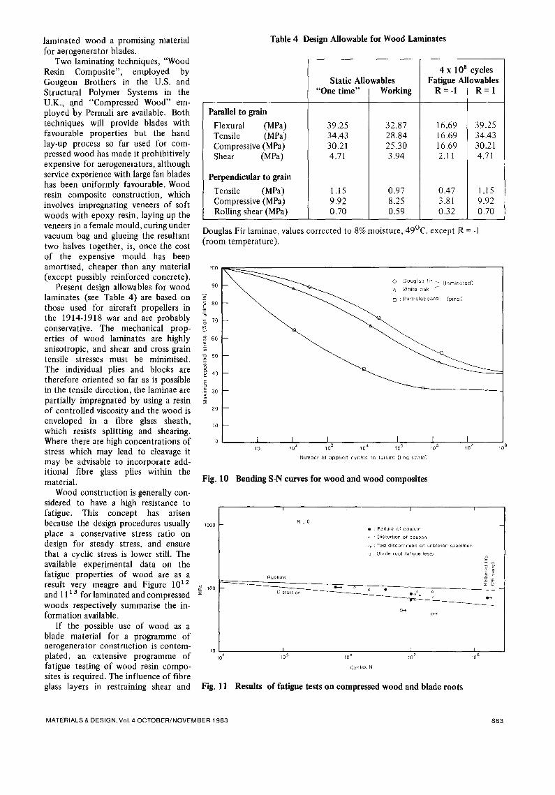
Wood construction is generally con- sidered to have a high resistance to fatigue. This concept has arisen because the design procedures usually place a conservative stress ratio on design for steady stress, and ensure that a cyclic stress is lower still. The available experimental data on the fatigue properties of wood are as a result very meagre and Figure 1012 and 11 a 3 for laminated and compressed woods respectively summarise the in- formation available.
If the possible use of wood as a blade material for a programme of aerogenerator construction is contem- plated, an extensive programme of fatigue testing of wood resin compo- sites is required. The influence of fibre glass layers in restraining shear and
Static Allowables "One time" I Working
1
39.25 32.87 34.43 28.84 30.21 25.30
Parallel to grain
Flexural (MPa) Tensile (MPa) Compressive (MPa) Shear (MPa)
Perpendicular to grain
Tensile (MPa) Compressive (MPa) Rolling shear (MPa)
4.71
100
1.15 9.92 0.70
3.94
0.97 8.25 0.59
4 x 10 a cycles Fatigue Allowables
R=-I R = 1
16.69 39.25 16.69 34.43 16.69 30.21 2.11 4.71
0.47 1.15 3.81 9.92 0.32 0.70
Douglas Fir laminae, values corrected to 8% moisture, 49°C, except R = -1 (room temperature).
0 : Douglas tir ~ [ l am ina ted ]
A : White oak / 9O
8o
-5 7O
60
¥ 5o
¢o 40
E_~× aO2olO f
0
Table 4 Design Allowable for Wood Laminates
I I l I 1 I I 10 10 .2 103 10 ~" 105 106 107
Number of app l ied cyc les to ta i lure [Log scale)
10 ~
Fig. 10 Bending S-N curves for wood and wood composites
1000
~oo
I I I I
R : 0
Rupture
Distortion
• : Failure of coupon
: Dislortion of coupon
: Test discontinued on unbroken specwnen
a Blade root ta~igue tests =
g~ cc
10 I I I I 10 105 106 ~07 108
Cycles N
Fig. 11 Results of fatigue tests on compressed wood and blade roots
M A T E R I A L S & D E S I G N , Vo l . 4 O C T O B E R / N O V E M B E R 1 9 8 3 8 8 3
cleavage should be studied and torsion- al fatigue tests which are most likely to induce these should be included.
The major influence of environ- ment on wood is that caused by the absorption or loss of moisture. These effects are much reduced by the partial impregnation with epoxy and the outer layer of fibre glass. It is important however, to ensure that the moisture content of a wooden component remains sensibly constant, and parts should be fabricated in an environment resembling the operating environment as closely as possible.
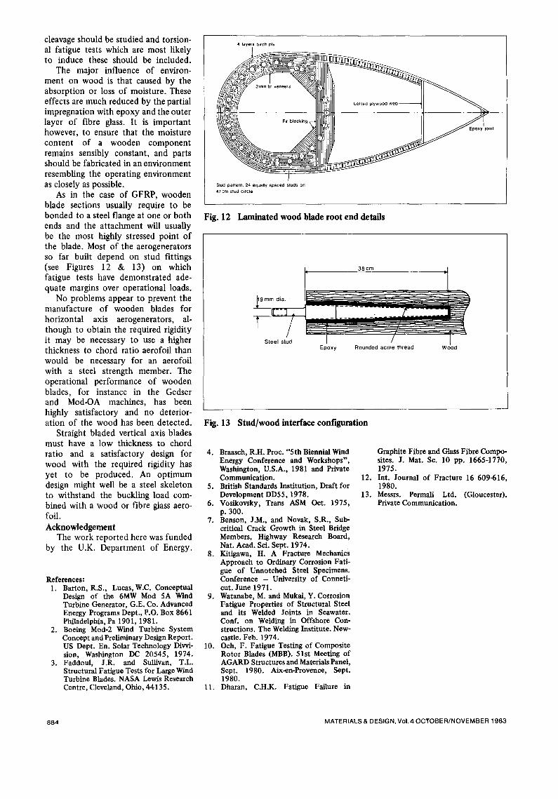
As in the case of GFRP, wooden blade sections usually require to be bonded to a steel flange at one or both ends and the attachment will usually be the most highly stressed point of the blade. Most of the aerogenerators so far built depend on stud fittings (see Figures 12 & 13) on which fatigue tests have demonstrated ade- quate margins over operational loads.
No problems appear to prevent the manufacture of wooden blades for horizontal axis aerogenerators, al- though to obtain the required rigidity it may be necessary to use a higher thickness to chord ratio aerofoil than would be necessary for an aerofoil with a steel strength member. The operational performance of wooden blades, for instance in the Gedser and Mod-OA machines, has been highly satisfactory and no deterior- ation of the wood has been detected.
Straight bladed vertical axis blades must have a low thickness to chord ratio and a satisfactory design for wood with the required rigidity has yet to be produced. An optimum design might well be a steel skeleton to withstand the buckling load com- bined with a wood or fibre glass aero- foil. Acknowledgement
The work reported here was funded by the U.K. Department of Energy.
References: 1. Barton, R.S., Lueas, W.C. Conceptual
Design of the 6MW Mod 5A Wind Turbine Generator, G.E. Co. Advanced Energy Programs Dept., P.O. Box 8661 Philadelphia, Pa 1901, 1981.
2. Boeing Mod-2 Wind Turbine System Concept and Preliminary Design Report. US Dept. En. Solar Technology Divvi- sion, Washington DC 20545, 1974.
3. Faddoul, J.R. and Sullivan, T.L. Structural Fatigue Tests for Large Wind Turbine Blades. NASA Lewis Research Centre, Cleveland, Ohio, 44135.
4 layers birch ply
3mm fir veneers
Lolted plywood
Stud pattern: 24 equally spaced studs on 47cm stud circle
Fig. 12 Laminated wood blade root end details
E p o x y R o u n d e d a c m e t h r e a d W o o d
Fig. 13 Stud/wood interface configuration
4. Braasch, R.H. Proc. "5th Biennial Wind Energy Conference and Workshops", Washington, U.S.A., 1981 and Private Communication.
5. British Standards Institution, Draft for Development DD55, 1978.
6. Vosikovsky, Trans ASM Oct. 1975, p. 300.
7. Benson, J.M., and Novak, S.R., Sub- critical Crack Growth in Steel Bridge Members, Highway Research Board, Nat. Aead. Sci. Sept. 1974.
8. Kitigawa, H. A Fracture Mechanics Approach to Ordinary Corrosion Fati- gue of Unnotched Steel Specimens. Conference - University of Conneti- cut. June 1971.
9. Watanabe, M. and Mukal, Y. Corrosion Fatigue Properties of Structural Steel and its Welded Joints in Seawater. Conf. on Welding in Offshore Con- structions. The Welding Institute. New- castle. Feb. 1974.
10. Och, F. Fatigue Testing of Composite Rotor Blades (MBB). 51st Meeting of AGARD Structures and Materials Panel, Sept. 1980. Aix-en-Provenee, Sept. 1980.
11. Dharan, C.H.K. Fatigue Failure in
Graphite Fibre and Glass Fibre Compo- sites. J. Mat. Se. 10 pp. 1665-1770, 1975.
12. Int. Journal of Fracture 16 609-616, 1980.
13. Messrs. Permali Ltd. (Gloucester). Private Communication.
884 MATERIALS & DESIGN, Vol. 4 OCTOBER/NOVEMBER 1983