materials data book - psna college of engineering and ... · 1 materials data book ... m f ashby...
TRANSCRIPT

1
MaterialsData Book
2003 Edition
Cambridge University Engineering Department
2
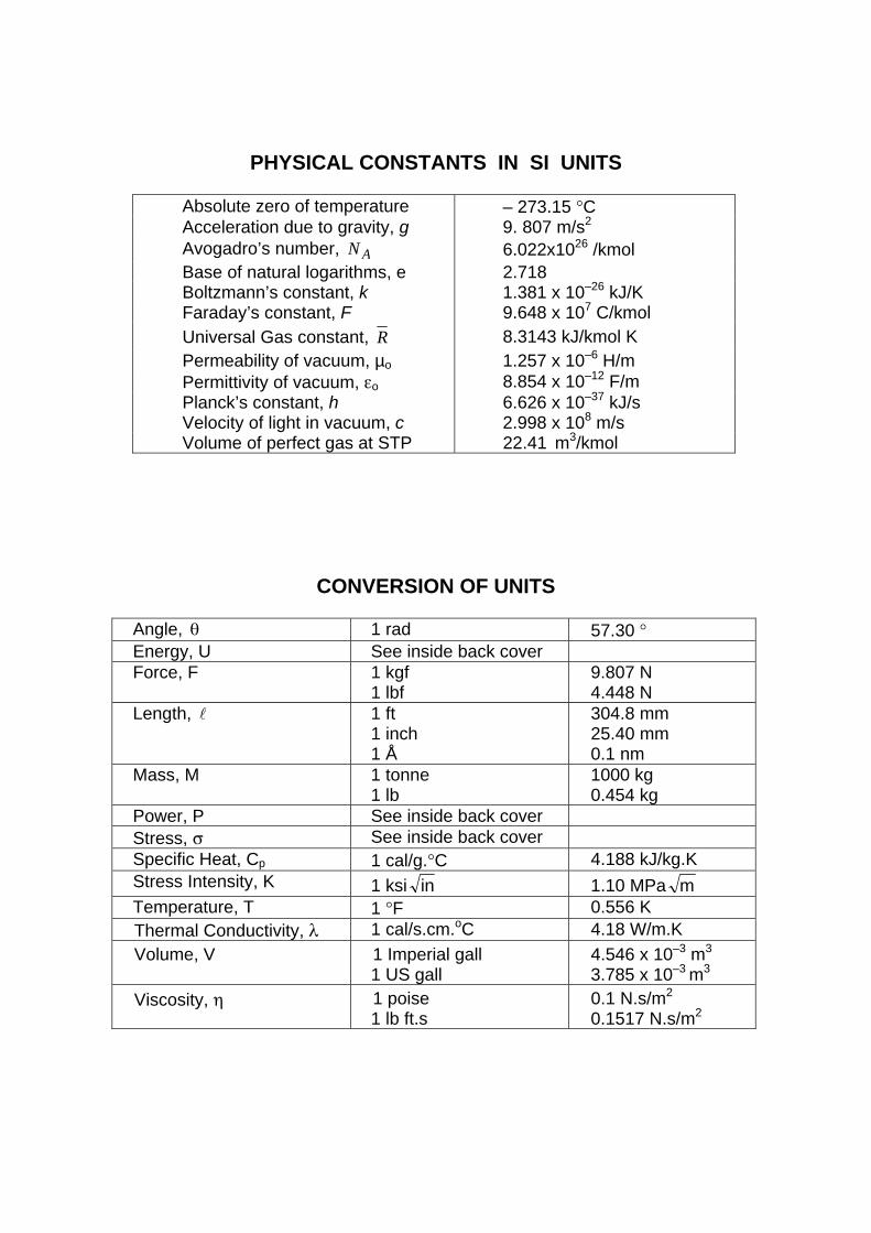
PHYSICAL CONSTANTS IN SI UNITS
Absolute zero of temperature – 273.15 °C Acceleration due to gravity, g 9. 807 m/s2 Avogadro’s number, AN 6.022x1026 /kmol Base of natural logarithms, e 2.718 Boltzmann’s constant, k 1.381 x 10⁻²⁶ kJ/K Faraday’s constant, F 9.648 x 10⁷ C/kmol Universal Gas constant, R 8.3143 kJ/kmol K Permeability of vacuum, µo 1.257 x 10⁻⁶ H/m Permittivity of vacuum, εo 8.854 x 10⁻¹² F/m Planck’s constant, h 6.626 x 10–37 kJ/s Velocity of light in vacuum, c 2.998 x 10⁸ m/s Volume of perfect gas at STP 22.41 m3/kmol
CONVERSION OF UNITS
Angle, θ 1 rad 57.30 ° Energy, U See inside back cover Force, F 1 kgf
1 lbf 9.807 N 4.448 N
Length, l 1 ft 1 inch 1 Å
304.8 mm 25.40 mm 0.1 nm
Mass, M 1 tonne 1 lb
1000 kg 0.454 kg
Power, P See inside back cover Stress, σ See inside back cover Specific Heat, Cp 1 cal/g.°C 4.188 kJ/kg.K Stress Intensity, K 1 ksi in 1.10 MPa m Temperature, T 1 °F 0.556 K Thermal Conductivity, λ 1 cal/s.cm.oC 4.18 W/m.K Volume, V 1 Imperial gall
1 US gall 4.546 x 10⁻³ m3
3.785 x 10⁻³ m3 Viscosity, η 1 poise
1 lb ft.s 0.1 N.s/m2
0.1517 N.s/m2

1
CONTENTS Page Number
Introduction 3 Sources 3
I. FORMULAE AND DEFINITIONS
Stress and strain 4 Elastic moduli 4
Stiffness and strength of unidirectional composites 5 Dislocations and plastic flow 5 Fast fracture 6 Statistics of fracture 6 Fatigue 7 Creep 7 Diffusion 8
Heat flow 8
II. PHYSICAL AND MECHANICAL PROPERTIES OF MATERIALS Melting temperature 9 Density 10 Young’s modulus 11 Yield stress and tensile strength 12 Fracture toughness 13 Environmental resistance 14 Uniaxial tensile response of selected metals and polymers 15
III. MATERIAL PROPERTY CHARTS Young’s modulus versus density 16 Strength versus density 17 Young’s modulus versus strength 18 Fracture toughness versus strength 19 Maximum service temperature 20 Material price (per kg) 21
IV. PROCESS ATTRIBUTE CHARTS Material-process compatibility matrix (shaping) 22
Mass 23 Section thickness 23 Surface roughness 24 Dimensional tolerance 24 Economic batch size 25

2
V. CLASSIFICATION AND APPLICATIONS OF ENGINEERING MATERIALS Metals: ferrous alloys, non-ferrous alloys 26 Polymers and foams 27 Composites, ceramics, glasses and natural materials 28
VI. EQUILIBRIUM (PHASE) DIAGRAMS Copper – Nickel 29 Lead – Tin 29 Iron – Carbon 30 Aluminium – Copper 30 Aluminium – Silicon 31 Copper – Zinc 31 Copper – Tin 32 Titanium-Aluminium 32 Silica – Alumina 33
VII. HEAT TREATMENT OF STEELS TTT diagrams and Jominy end-quench hardenability curves for steels 34
VIII. PHYSICAL PROPERTIES OF SELECTED ELEMENTS Atomic properties of selected elements 36 Oxidation properties of selected elements 37
3
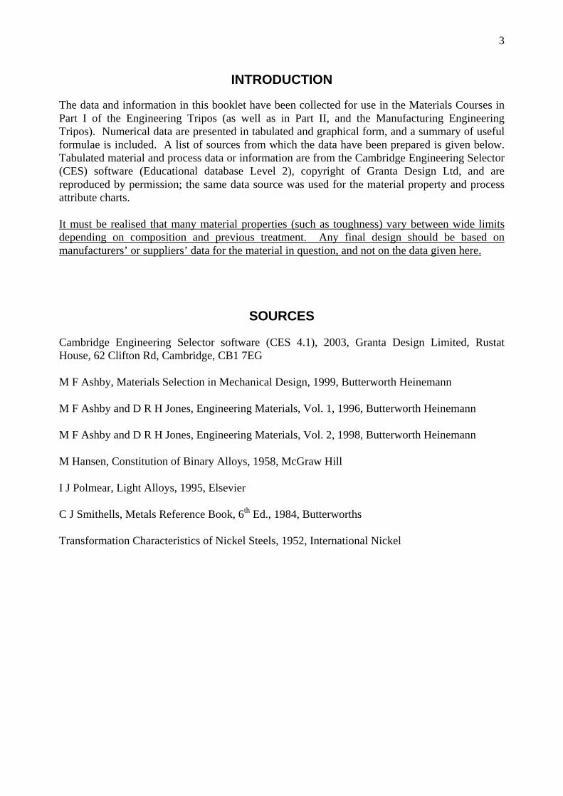
INTRODUCTION The data and information in this booklet have been collected for use in the Materials Courses in Part I of the Engineering Tripos (as well as in Part II, and the Manufacturing Engineering Tripos). Numerical data are presented in tabulated and graphical form, and a summary of useful formulae is included. A list of sources from which the data have been prepared is given below. Tabulated material and process data or information are from the Cambridge Engineering Selector (CES) software (Educational database Level 2), copyright of Granta Design Ltd, and are reproduced by permission; the same data source was used for the material property and process attribute charts. It must be realised that many material properties (such as toughness) vary between wide limits depending on composition and previous treatment. Any final design should be based on manufacturers’ or suppliers’ data for the material in question, and not on the data given here.
SOURCES
Cambridge Engineering Selector software (CES 4.1), 2003, Granta Design Limited, Rustat House, 62 Clifton Rd, Cambridge, CB1 7EG M F Ashby, Materials Selection in Mechanical Design, 1999, Butterworth Heinemann M F Ashby and D R H Jones, Engineering Materials, Vol. 1, 1996, Butterworth Heinemann M F Ashby and D R H Jones, Engineering Materials, Vol. 2, 1998, Butterworth Heinemann M Hansen, Constitution of Binary Alloys, 1958, McGraw Hill I J Polmear, Light Alloys, 1995, Elsevier C J Smithells, Metals Reference Book, 6th Ed., 1984, Butterworths Transformation Characteristics of Nickel Steels, 1952, International Nickel

4
I. FORMULAE AND DEFINITIONS
STRESS AND STRAIN
AF
t =σ oA
Fn =σ
=
ot
l
llnε o
on
l
ll −=ε
F = normal component of force tσ = true stress
oA = initial area nσ = nominal stress A = current area tε = true strain
ol = initial length nε = nominal strain l = current length
Poisson’s ratio, strainallongitudin
strainlateral−=ν
Young’s modulus E = initial slope of tt εσ − curve = initial slope of nn εσ − curve. Yield stress yσ is the nominal stress at the limit of elasticity in a tensile test. Tensile strength tsσ is the nominal stress at maximum load in a tensile test. Tensile ductility fε is the nominal plastic strain at failure in a tensile test. The gauge length of the specimen should also be quoted.
ELASTIC MODULI
)1(2 ν+= EG
)21(3 ν−= EK
For polycrystalline solids, as a rough guide,
Poisson’s Ratio 31≈ν
Shear Modulus EG83≈
Bulk Modulus EK ≈
These approximations break down for rubber and porous solids.

5
STIFFNESS AND STRENGTH OF UNIDIRECTIONAL COMPOSITES
mfffII E)V(EVE −+= 1
11 −
⊥
−+=
m
f
f
f
EV
EV
E
mf 1 yfffts )V(V σσσ −+=
IIE = composite modulus parallel to fibres (upper bound)
⊥E = composite modulus transverse to fibres (lower bound)
fV = volume fraction of fibres
fE = Young’s modulus of fibres
mE = Young’s modulus of matrix
tsσ = tensile strength of composite parallel to fibres ffσ = fracture strength of fibres
myσ = yield stress of matrix
DISLOCATIONS AND PLASTIC FLOW
The force per unit length F on a dislocation, of Burger’s vector b , due to a remote shear stress τ , is bF τ= . The shear stress yτ required to move a dislocation on a single slip plane is
LbTc
y =τ where T = line tension (about 221 bG , where G is the shear modulus)
L = inter-obstacle distance c = constant ( 2≈c for strong obstacles, 2<c for weak obstacles) The shear yield stress k of a polycrystalline solid is related to the shear stress yτ required to
move a dislocation on a single slip plane: yk τ23≈ .
The uniaxial yield stress yσ of a polycrystalline solid is approximately ky 2=σ , where k is the shear yield stress.
Hardness H (in MPa) is given approximately by: yH σ3≈ .
Vickers Hardness HV is given in kgf/mm2, i.e. g/HHV = , where g is the acceleration due to gravity.

6
FAST FRACTURE
The stress intensity factor, K : aYK πσ=
Fast fracture occurs when ICKK =
In plane strain, the relationship between stress intensity factor K and strain energy release rate G is:
GEEGK ≈−
=21 ν
(as 102 .≈ν )
Plane strain fracture toughness and toughness are thus related by: IC2IC
IC1
GEGE
K ≈−
=ν
“Process zone size” at crack tip given approximately by: 2
2IC
fp
Kr
σπ=
Note that ICK (and ICG ) are only valid when conditions for linear elastic fracture mechanics apply (typically the crack length and specimen dimensions must be at least 50 times the process zone size).
In the above: σ = remote tensile stress a = crack length Y = dimensionless constant dependent on geometry; typically 1≈Y
ICK = plane strain fracture toughness;
ICG = critical strain energy release rate, or toughness; E = Young’s modulus ν = Poisson’s ratio
fσ = failure strength
STATISTICS OF FRACTURE
Weibull distribution,
−= ∫ o
m
os V
dV
V(V)P
σσexp
For constant stress:
−=
o
m
os V
V(V)Pσσexp
sP = survival probability of component V = volume of component σ = tensile stress on component
oV = volume of test sample
oσ = reference failure stress for volume oV , which gives 3701 .P es ==
m = Weibull modulus

7
FATIGUE
Basquin’s Law (high cycle fatigue):
1CN f =ασ∆
Coffin-Manson Law (low cycle fatigue):
2CN fp =βε∆ l
Goodman’s Rule. For the same fatigue life, a stress range σ∆ operating with a mean stress mσ , is equivalent to a stress range oσ∆ and zero mean stress, according to the relationship:
−=
ts
mo σ
σσ∆σ∆ 1
Miner’s Rule for cumulative damage (for i loading blocks, each of constant stress amplitude and duration iN cycles):
1=∑fi
iNN
i
Paris’ crack growth law:
nKANdad ∆=
In the above: σ∆ = stress range;
=lpε∆ plastic strain range; K∆ = tensile stress intensity range;
N = cycles; fN = cycles to failure;
=n,A,C,C,, 21βα constants; a = crack length;
tsσ = tensile strength.
CREEP
Power law creep: )RT/Q(A nss −= expσε&
ssε& = steady-state strain-rate
Q = activation energy (kJ/kmol) R = universal gas constant T = absolute temperature
n,A = constants

8
DIFFUSION
Diffusion coefficient: )RT/Q(DD o −= exp
Fick’s diffusion equations: dxdCDJ −= and
2
2
xCD
tC
∂
∂=∂∂
C = concentration J = diffusive flux x = distance D = diffusion coefficient (m2/s) t = time oD = pre-exponential factor (m2/s)
Q = activation energy (kJ/kmol)
HEAT FLOW
Steady-state 1D heat flow (Fourier’s Law): dxdTq λ−=
Transient 1D heat flow: 2
2
xTa
tT
∂
∂=∂∂
T = temperature (K) λ = thermal conductivity (W/m.K) q = heat flux per second, per unit area (W/m2.s) a = thermal diffusivity (m2/s)
For many 1D problems of diffusion and heat flow, the solution for concentration or temperature depends on the error function, erf :
=
tDxf)t,x(C
2erf or
=
taxf)t,x(T
2erf
A characteristic diffusion distance in all problems is given by tDx ≈ , with the corresponding
characteristic heat flow distance in thermal problems being tax ≈ . The error function, and its first derivative, are:
( ) dyyX
)X( 20
exp2
erf −= ∫π ( )2exp
2erfand X)]X([
dXd −=
π
The error function integral has no closed form solution – values are given in the Table below.
X 0 0.1 0.2 0.3 0.4 0.5 0.6 0.7 0.8 )(Xerf 0 0.11 0.22 0.33 0.43 0.52 0.60 0.68 0.74
X 0.9 1.0 1.1 1.2 1.3 1.4 1.5 ∞
)(Xerf 0.80 0.84 0.88 0.91 0.93 0.95 0.97 1.0

9
T m
(o C)
Met
als
Ferr
ous
Cas
t Iro
ns
1130
-
1250
Hig
h C
arbo
n S
teel
s 12
89
- 14
78
M
ediu
m C
arbo
n S
teel
s 13
80
- 15
14
Lo
w C
arbo
n S
teel
s 14
80
- 15
26
Lo
w A
lloy
Ste
els
1382
-
1529
Sta
inle
ss S
teel
s 13
75
- 14
50
Non
-ferr
ous
Alu
min
ium
Allo
ys
475
- 67
7
Cop
per A
lloys
98
2 -
1082
Lead
Allo
ys
322
- 32
8
Mag
nesi
um A
lloys
44
7 -
649
N
icke
l Allo
ys
1435
-
1466
Tita
nium
Allo
ys
1477
-
1682
Zinc
Allo
ys
375
- 49
2 C
eram
ics
Gla
sses
Bor
osili
cate
Gla
ss (
*)
450
- 60
2
Gla
ss C
eram
ic (
*)
563
- 16
47
S
ilica
Gla
ss (
*)
957
- 15
57
S
oda-
Lim
e G
lass
(*)
44
2 -
592
Por
ous
Bric
k 92
7 -
1227
Con
cret
e, ty
pica
l 92
7 -
1227
Sto
ne
1227
-
1427
Te
chni
cal
Alu
min
a 20
04
20
96
A
lum
iniu
m N
itrid
e 23
97
- 25
07
B
oron
Car
bide
23
72
- 25
07
S
ilico
n 14
07
- 14
12
S
ilico
n C
arbi
de
2152
-
2500
Sili
con
Nitr
ide
2388
-
2496
Tung
sten
Car
bide
28
27
- 29
20
Com
posi
tes
Met
al
Alu
min
ium
/Sili
con
Car
bide
52
5 -
627
Pol
ymer
C
FRP
n/
a
GFR
P
n/a
Nat
ural
Bam
boo
(*)
77
- 10
2
Cor
k (*
) 77
-
102
Le
athe
r (*
) 10
7 -
127
W
ood,
typi
cal (
Long
itudi
nal)
(*)
77
-
102
W
ood,
typi
cal (
Tran
sver
se)
(*)
77
- 10
2
T m (o C
) Po
lym
ers
1
E
last
omer
B
utyl
Rub
ber
(*)
– 73
-
– 63
EV
A (
*)
– 73
-
– 23
Isop
rene
(IR
) (*
) –
83
- –
78
N
atur
al R
ubbe
r (N
R)
(*)
– 78
-
– 63
Neo
pren
e (C
R)
(*)
– 48
-
– 43
Pol
yure
than
e E
last
omer
s (e
lPU
) (*
) –
73
- –
23
S
ilico
ne E
last
omer
s (*
) –
123
- –
73
Ther
mop
last
ic
AB
S (
*)
88
- 1
28
C
ellu
lose
Pol
ymer
s (C
A)
(*)
– 9
- 1
07
Io
nom
er (I
) (*
) 27
-
77
N
ylon
s (P
A)
(*)
44
- 5
6
Pol
ycar
bona
te (P
C)
(*)
142
- 2
05
P
EE
K (
*)
143
- 1
99
P
olye
thyl
ene
(PE
) (*
) –
25
- –
15
P
ET
(*)
68
- 8
0
Acr
ylic
(PM
MA
) (*
) 85
-
165
Ace
tal (
PO
M)
(*)
– 18
-
– 8
P
olyp
ropy
lene
(PP
) (*
) –
25
- –
15
P
olys
tyre
ne (P
S)
(*)
74
-
110
P
olyu
reth
ane
Ther
mop
last
ics
(tpP
U)
(*)
120
- 1
60
P
VC
75
-
105
Teflo
n (P
TFE
) 10
7 -
123
Th
erm
oset
E
poxi
es
n/a
P
heno
lics
n/a
P
olye
ster
n/
a Po
lym
er F
oam
s
Flex
ible
Pol
ymer
Foa
m (V
LD)
(*)
112
- 17
7
Flex
ible
Pol
ymer
Foa
m (L
D)
(*)
112
- 17
7
Flex
ible
Pol
ymer
Foa
m (M
D)
(*)
112
- 17
7
Rig
id P
olym
er F
oam
(LD
) (*
) 67
-
171
R
igid
Pol
ymer
Foa
m (M
D)
(*)
67
- 15
7
Rig
id P
olym
er F
oam
(HD
) (*
) 67
-
171
1 For
full
nam
es a
nd a
cron
yms o
f pol
ymer
s – se
e Se
ctio
n V
. (*
) gl
ass t
rans
ition
(sof
teni
ng) t
empe
ratu
re
n/a:
not
app
licab
le (m
ater
ials
dec
ompo
se, r
athe
r tha
n m
elt)
II. P
HY
SIC
AL
AN
D M
EC
HA
NIC
AL
PR
OP
ER
TIE
S O
F M
ATE
RIA
LS
II.1
MEL
TIN
G (
or S
OFT
ENIN
G)
TEM
PER
ATU
RE,
Tm
A
ll da
ta a
re f
or m
eltin
g po
ints
at
atm
osph
eric
pre
ssur
e.
For
poly
mer
s (a
nd g
lass
es)
the
data
ind
icat
e th
e gl
ass
trans
ition
(so
fteni
ng)
tem
pera
ture
, abo
ve w
hich
the
mec
hani
cal p
rope
rties
rapi
dly
fall.
M
eltin
g te
mpe
ratu
res o
f sel
ecte
d el
emen
ts a
re g
iven
in se
ctio
n V
III.

10
ρ
(Mg/
m3 )
Met
als
Ferr
ous
Cas
t Iro
ns
7.05
-
7.25
Hig
h C
arbo
n S
teel
s 7.
8 -
7.9
M
ediu
m C
arbo
n S
teel
s 7.
8 -
7.9
Lo
w C
arbo
n S
teel
s 7.
8 -
7.9
Lo
w A
lloy
Ste
els
7.8
- 7.
9
Sta
inle
ss S
teel
s 7.
6 -
8.1
Non
-ferr
ous
Alu
min
ium
Allo
ys
2.5
- 2.
9
Cop
per A
lloys
8.
93
- 8.
94
Le
ad A
lloys
10
-
11.4
Mag
nesi
um A
lloys
1.
74
- 1.
95
N
icke
l Allo
ys
8.83
-
8.95
Tita
nium
Allo
ys
4.4
- 4.
8
Zinc
Allo
ys
4.95
-
7 C
eram
ics
Gla
sses
Bor
osili
cate
Gla
ss
2.2
- 2.
3
Gla
ss C
eram
ic
2.2
- 2.
8
Sili
ca G
lass
2.
17
- 2.
22
S
oda-
Lim
e G
lass
2.
44
- 2.
49
Por
ous
Bric
k 1.
9 -
2.1
C
oncr
ete,
typi
cal
2.2
- 2.
6
Sto
ne
2.5
- 3
Tech
nica
l A
lum
ina
3.5
3.
98
A
lum
iniu
m N
itrid
e 3.
26
- 3.
33
B
oron
Car
bide
2.
35
- 2.
55
S
ilico
n 2.
3 -
2.35
Sili
con
Car
bide
3
- 3.
21
S
ilico
n N
itrid
e 3
- 3.
29
Tu
ngst
en C
arbi
de
15.3
-
15.9
C
ompo
site
s
M
etal
A
lum
iniu
m/S
ilico
n C
arbi
de
2.66
-
2.9
Pol
ymer
C
FRP
1.
5 -
1.6
G
FRP
1.
75
- 1.
97
Nat
ural
Bam
boo
0.
6 -
0.8
C
ork
0.
12
- 0.
24
Le
athe
r
0.81
-
1.05
Woo
d, ty
pica
l (Lo
ngitu
dina
l)
0.6
- 0.
8
Woo
d, ty
pica
l (Tr
ansv
erse
)
0.6
- 0.
8
ρ (M
g/m
3 ) Po
lym
ers
1
E
last
omer
B
utyl
Rub
ber
0.
9 -
0.92
EV
A
0.94
5 -
0.95
5
Isop
rene
(IR
)
0.93
-
0.94
Nat
ural
Rub
ber (
NR
)
0.92
-
0.93
Neo
pren
e (C
R)
1.
23
- 1.
25
P
olyu
reth
ane
Ela
stom
ers
(elP
U)
1.
02
- 1.
25
S
ilico
ne E
last
omer
s
1.3
- 1.
8 Th
erm
opla
stic
A
BS
1.
01
- 1.
21
C
ellu
lose
Pol
ymer
s (C
A)
0.
98
- 1.
3
Iono
mer
(I)
0.
93
- 0.
96
N
ylon
s (P
A)
1.
12
- 1.
14
P
olyc
arbo
nate
(PC
)
1.14
-
1.21
PE
EK
1.
3 -
1.32
Pol
yeth
ylen
e (P
E)
0.
939
- 0.
96
P
ET
1.
29
- 1.
4
Acr
ylic
(PM
MA
)
1.16
-
1.22
Ace
tal (
PO
M)
1.
39
- 1.
43
P
olyp
ropy
lene
(PP
)
0.89
-
0.91
Pol
ysty
rene
(PS
)
1.04
-
1.05
Pol
yure
than
e Th
erm
opla
stic
s (tp
PU
) 1.
12
- 1.
24
P
VC
1.
3 -
1.58
Teflo
n (P
TFE
) 2.
14
- 2.
2 Th
erm
oset
E
poxi
es
1.11
-
1.4
P
heno
lics
1.24
-
1.32
Pol
yest
er
1.04
-
1.4
Poly
mer
Foa
ms
Fl
exib
le P
olym
er F
oam
(VLD
) 0.
016
- 0.
035
Fl
exib
le P
olym
er F
oam
(LD
) 0.
038
- 0.
07
Fl
exib
le P
olym
er F
oam
(MD
) 0.
07
- 0.
115
R
igid
Pol
ymer
Foa
m (L
D)
0.
036
- 0.
07
R
igid
Pol
ymer
Foa
m (M
D)
0.
078
- 0.
165
R
igid
Pol
ymer
Foa
m (H
D)
0.
17
- 0.
47
1 For
full
nam
es a
nd a
cron
yms o
f pol
ymer
s – se
e Se
ctio
n V
.
II.2
D
ENSI
TY,
ρ

11
E
(G
Pa)
M
etal
s
Fe
rrou
s C
ast I
rons
16
5 -
180
H
igh
Car
bon
Ste
els
200
- 21
5
Med
ium
Car
bon
Ste
els
200
- 21
6
Low
Car
bon
Ste
els
200
- 21
5
Low
Allo
y S
teel
s 20
1 -
217
S
tain
less
Ste
els
189
- 21
0 N
on-fe
rrou
s A
lum
iniu
m A
lloys
68
-
82
C
oppe
r Allo
ys
112
- 14
8
Lead
Allo
ys
12.5
-
15
M
agne
sium
Allo
ys
42
- 47
Nic
kel A
lloys
19
0 -
220
Ti
tani
um A
lloys
90
-
120
Zi
nc A
lloys
68
-
95
Cer
amic
s
G
lass
esB
oros
ilica
te G
lass
61
-
64
G
lass
Cer
amic
64
-
110
S
ilica
Gla
ss
68
- 74
Sod
a-Li
me
Gla
ss
68
- 72
P
orou
s B
rick
10
- 50
Con
cret
e, ty
pica
l 25
-
38
S
tone
6.
9 -
21
Tech
nica
l A
lum
ina
215
41
3
Alu
min
ium
Nitr
ide
302
- 34
8
Bor
on C
arbi
de
400
- 47
2
Sili
con
140
- 15
5
Sili
con
Car
bide
30
0 -
460
S
ilico
n N
itrid
e 28
0 -
310
Tu
ngst
en C
arbi
de
600
- 72
0 C
ompo
site
s
M
etal
A
lum
iniu
m/S
ilico
n C
arbi
de
81
- 10
0 P
olym
er
CFR
P
69
- 15
0
GFR
P
15
- 28
N
atur
al
B
ambo
o
15
- 20
Cor
k
0.01
3 -
0.05
Leat
her
0.
1 -
0.5
W
ood,
typi
cal (
Long
itudi
nal)
6
- 20
Woo
d, ty
pica
l (Tr
ansv
erse
)
0.5
- 3
E (
GP
a)
Poly
mer
s 1
Ela
stom
er
But
yl R
ubbe
r
0.00
1 -
0.00
2
EV
A
0.01
-
0.04
Isop
rene
(IR
)
0.00
14
- 0.
004
N
atur
al R
ubbe
r (N
R)
0.
0015
-
0.00
25
N
eopr
ene
(CR
)
0.00
07
- 0.
002
P
olyu
reth
ane
Ela
stom
ers
(elP
U)
0.
002
- 0.
003
S
ilico
ne E
last
omer
s
0.00
5 -
0.02
Th
erm
opla
stic
A
BS
1.
1 -
2.9
C
ellu
lose
Pol
ymer
s (C
A)
1.
6 -
2
Iono
mer
(I)
0.
2 -
0.42
4
Nyl
ons
(PA
)
2.62
-
3.2
P
olyc
arbo
nate
(PC
)
2 -
2.44
PE
EK
3.
5 -
4.2
P
olye
thyl
ene
(PE
)
0.62
1 -
0.89
6
PE
T
2.76
-
4.14
Acr
ylic
(PM
MA
)
2.24
-
3.8
A
ceta
l (P
OM
)
2.5
- 5
P
olyp
ropy
lene
(PP
)
0.89
6 -
1.55
Pol
ysty
rene
(PS
)
2.28
-
3.34
Pol
yure
than
e Th
erm
opla
stic
s (tp
PU
) 1.
31
- 2.
07
P
VC
2.
14
- 4.
14
Te
flon
(PTF
E)
0.4
- 0.
552
Ther
mos
et
Epo
xies
2.
35
- 3.
075
P
heno
lics
2.76
-
4.83
Pol
yest
er
2.07
-
4.41
Po
lym
er F
oam
s
Flex
ible
Pol
ymer
Foa
m (V
LD)
0.00
03
- 0.
001
Fl
exib
le P
olym
er F
oam
(LD
) 0.
001
- 0.
003
Fl
exib
le P
olym
er F
oam
(MD
) 0.
004
- 0.
012
R
igid
Pol
ymer
Foa
m (L
D)
0.
023
- 0.
08
R
igid
Pol
ymer
Foa
m (M
D)
0.
08
- 0.
2
Rig
id P
olym
er F
oam
(HD
)
0.2
- 0.
48
1 For
full
nam
es a
nd a
cron
yms o
f pol
ymer
s – se
e Se
ctio
n V
.
II.3
YO
UN
G’S
MO
DU
LUS,
E

12
σ y
(MP
a)
σ ts (
MP
a)
Met
als
Fe
rrou
s C
ast I
rons
21
5 -
790
350
- 10
00
H
igh
Car
bon
Ste
els
400
- 11
55
550
- 16
40
M
ediu
m C
arbo
n S
teel
s 30
5 -
900
410
- 12
00
Lo
w C
arbo
n S
teel
s 25
0 -
395
345
- 58
0
Low
Allo
y S
teel
s 40
0 -
1100
46
0 -
1200
Sta
inle
ss S
teel
s 17
0 -
1000
48
0 -
2240
N
on-fe
rrou
s A
lum
iniu
m A
lloys
30
-
500
58
- 55
0
Cop
per A
lloys
30
-
500
100
- 55
0
Lead
Allo
ys
8 -
14
12
- 20
Mag
nesi
um A
lloys
70
-
400
185
- 47
5
Nic
kel A
lloys
70
-
1100
34
5 -
1200
Tita
nium
Allo
ys
250
- 12
45
300
- 16
25
Zi
nc A
lloys
80
-
450
135
- 52
0 C
eram
ics
G
lass
es
Bor
osili
cate
Gla
ss (*
) 26
4 -
384
22
- 32
Gla
ss C
eram
ic (
*)
750
- 21
29
62
- 17
7
Sili
ca G
lass
(*)
11
00
- 16
00
45
- 15
5
Sod
a-Li
me
Gla
ss (
*)
360
- 42
0 31
-
35
Por
ous
Bric
k (*
) 50
-
140
7 -
14
C
oncr
ete,
typi
cal
(*)
32
- 60
2
- 6
S
tone
(*)
34
-
248
5 -
17
Tech
nica
l A
lum
ina
(*)
690
55
00
350
66
5
Alu
min
ium
Nitr
ide
(*)
1970
-
2700
19
7 -
270
B
oron
Car
bide
(*)
25
83
- 56
87
350
- 56
0
Sili
con
(*)
3200
-
3460
16
0 -
180
S
ilico
n C
arbi
de (
*)
1000
-
5250
37
0 -
680
S
ilico
n N
itrid
e (*
) 52
4 -
5500
69
0 -
800
Tu
ngst
en C
arbi
de (
*)
3347
-
6833
37
0 -
550
Com
posi
tes
M
etal
A
lum
iniu
m/S
ilico
n C
arbi
de
280
- 32
4 29
0 -
365
Pol
ymer
C
FRP
55
0 -
1050
55
0 -
1050
GFR
P
110
- 19
2 13
8 -
241
Nat
ural
B
ambo
o 35
-
44
36
- 45
Cor
k 0.
3 -
1.5
0.5
- 2.
5
Leat
her
5 -
10
20
- 26
Woo
d, ty
pica
l (Lo
ngitu
dina
l) 30
-
70
60
- 10
0
Woo
d, ty
pica
l (Tr
ansv
erse
) 2
- 6
4 -
9
σ y (M
Pa)
σ t
s (M
Pa)
Po
lym
ers
1
Ela
stom
er
But
yl R
ubbe
r 2
- 3
5 -
10
E
VA
12
-
18
16
- 20
Isop
rene
(IR
) 20
-
25
20
- 25
Nat
ural
Rub
ber (
NR
) 20
-
30
22
- 32
Neo
pren
e (C
R)
3.4
- 24
3.
4 -
24
P
olyu
reth
ane
Ela
stom
ers
(elP
U)
25
- 51
25
-
51
S
ilico
ne E
last
omer
s 2.
4 -
5.5
2.4
- 5.
5 Th
erm
opla
stic
A
BS
18
.5
- 51
27
.6
- 55
.2
C
ellu
lose
Pol
ymer
s (C
A)
25
- 45
25
-
50
Io
nom
er (I
) 8.
3 -
15.9
17
.2
- 37
.2
N
ylon
s (P
A)
50
- 94
.8
90
- 16
5
Pol
ycar
bona
te (P
C)
59
- 70
60
-
72.4
PE
EK
65
-
95
70
- 10
3
Pol
yeth
ylen
e (P
E)
17.9
-
29
20.7
-
44.8
PE
T 56
.5
- 62
.3
48.3
-
72.4
Acr
ylic
(PM
MA
) 53
.8
- 72
.4
48.3
-
79.6
Ace
tal (
PO
M)
48.6
-
72.4
60
-
89.6
Pol
ypro
pyle
ne (P
P)
20.7
-
37.2
27
.6
- 41
.4
P
olys
tyre
ne (P
S)
28.7
-
56.2
35
.9
- 56
.5
P
olyu
reth
ane
Ther
mop
last
ics
(tpP
U)
40
- 53
.8
31
- 62
PV
C
35.4
-
52.1
40
.7
- 65
.1
Te
flon
(PTF
E)
15
- 25
20
-
30
Ther
mos
et
Epo
xies
36
-
71.7
45
-
89.6
Phe
nolic
s 27
.6
- 49
.7
34.5
-
62.1
Pol
yest
er
33
- 40
41
.4
- 89
.6
Poly
mer
Foa
ms
Flex
ible
Pol
ymer
Foa
m (V
LD)
0.01
-
0.12
0.
24
- 0.
85
Fl
exib
le P
olym
er F
oam
(LD
) 0.
02
- 0.
3 0.
24
- 2.
35
Fl
exib
le P
olym
er F
oam
(MD
) 0.
05
- 0.
7 0.
43
- 2.
95
R
igid
Pol
ymer
Foa
m (L
D)
0.3
- 1.
7 0.
45
- 2.
25
R
igid
Pol
ymer
Foa
m (M
D)
0.4
- 3.
5 0.
65
- 5.
1
Rig
id P
olym
er F
oam
(HD
) 0.
8 -
12
1.2
- 12
.4
1 For
full
nam
es a
nd a
cron
yms o
f pol
ymer
s – se
e Se
ctio
n V
. (*
) N
B:
For c
eram
ics,
yiel
d st
ress
is re
plac
ed b
y co
mpr
essi
ve s
tren
gth,
w
hich
is m
ore
rele
vant
in c
eram
ic d
esig
n. N
ote
that
cer
amic
s ar
e of
the
orde
r of
10 ti
mes
stro
nger
in c
ompr
essi
on t
han
in te
nsio
n.
II.4
YI
ELD
STR
ESS,
σy,
AN
D T
ENSI
LE S
TREN
GTH
, σts
13
K
IC (
MP
a√m
) M
etal
s
Fe
rrou
s C
ast I
rons
22
-
54
H
igh
Car
bon
Ste
els
27
- 92
Med
ium
Car
bon
Ste
els
12
- 92
Low
Car
bon
Ste
els
41
- 82
Low
Allo
y S
teel
s 14
-
200
S
tain
less
Ste
els
62
- 28
0 N
on-fe
rrou
s A
lum
iniu
m A
lloys
22
-
35
C
oppe
r Allo
ys
30
- 90
Lead
Allo
ys
5 -
15
M
agne
sium
Allo
ys
12
- 18
Nic
kel A
lloys
80
-
110
Ti
tani
um A
lloys
14
-
120
Zi
nc A
lloys
10
-
100
Cer
amic
s
G
lass
esB
oros
ilica
te G
lass
0.
5 -
0.7
G
lass
Cer
amic
1.
4 -
1.7
S
ilica
Gla
ss
0.6
- 0.
8
Sod
a-Li
me
Gla
ss
0.55
-
0.7
Por
ous
Bric
k 1
- 2
C
oncr
ete,
typi
cal
0.35
-
0.45
Sto
ne
0.7
- 1.
5 Te
chni
cal
Alu
min
a 3.
3
4.8
A
lum
iniu
m N
itrid
e 2.
5 -
3.4
B
oron
Car
bide
2.
5 -
3.5
S
ilico
n 0.
83
- 0.
94
S
ilico
n C
arbi
de
2.5
- 5
S
ilico
n N
itrid
e 4
- 6
Tu
ngst
en C
arbi
de
2 -
3.8
Com
posi
tes
Met
al
Alu
min
ium
/Sili
con
Car
bide
15
-
24
Pol
ymer
C
FRP
6.
1 -
88
G
FRP
7
- 23
N
atur
al
B
ambo
o
5 -
7
Cor
k
0.05
-
0.1
Le
athe
r
3 -
5
Woo
d, ty
pica
l (Lo
ngitu
dina
l)
5 -
9
Woo
d, ty
pica
l (Tr
ansv
erse
)
0.5
- 0.
8
KIC
(M
Pa√
m)
Poly
mer
s 1
Ela
stom
er
But
yl R
ubbe
r
0.07
-
0.1
E
VA
0.
5 -
0.7
Is
opre
ne (I
R)
0.
07
- 0.
1
Nat
ural
Rub
ber (
NR
)
0.15
-
0.25
Neo
pren
e (C
R)
0.
1 -
0.3
P
olyu
reth
ane
Ela
stom
ers
(elP
U)
0.
2 -
0.4
S
ilico
ne E
last
omer
s
0.03
-
0.5
Ther
mop
last
ic
AB
S
1.19
-
4.30
Cel
lulo
se P
olym
ers
(CA
)
1 -
2.5
Io
nom
er (I
)
1.14
-
3.43
Nyl
ons
(PA
)
2.22
-
5.62
Pol
ycar
bona
te (P
C)
2.
1 -
4.60
PE
EK
2.
73
- 4.
30
P
olye
thyl
ene
(PE
)
1.44
-
1.72
PE
T
4.5
- 5.
5
Acr
ylic
(PM
MA
)
0.7
- 1.
6
Ace
tal (
PO
M)
1.
71
- 4.
2
Pol
ypro
pyle
ne (P
P)
3
- 4.
5
Pol
ysty
rene
(PS
)
0.7
- 1.
1
Pol
yure
than
e Th
erm
opla
stic
s (tp
PU
) 1.
84
- 4.
97
P
VC
1.
46
- 5.
12
Te
flon
(PTF
E)
1.32
-
1.8
Ther
mos
et
Epo
xies
0.
4 -
2.22
Phe
nolic
s 0.
79
- 1.
21
P
olye
ster
1.
09
- 1.
70
Poly
mer
Foa
ms
Fl
exib
le P
olym
er F
oam
(VLD
) 0.
005
- 0.
02
Fl
exib
le P
olym
er F
oam
(LD
) 0.
015
- 0.
05
Fl
exib
le P
olym
er F
oam
(MD
) 0.
03
- 0.
09
R
igid
Pol
ymer
Foa
m (L
D)
0.
002
- 0.
02
R
igid
Pol
ymer
Foa
m (M
D)
0.
007
- 0.
049
R
igid
Pol
ymer
Foa
m (H
D)
0.
024
- 0.
091
1 For
full
nam
es a
nd a
cron
yms o
f pol
ymer
s – se
e Se
ctio
n V
.
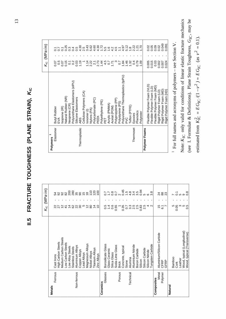
Not
e:IC
K o
nly
valid
for
con
ditio
ns o
f lin
ear
elas
tic f
ract
ure
mec
hani
cs
(see
I. F
orm
ulae
& D
efin
ition
s).
Plan
e St
rain
Tou
ghne
ss,
ICG
, may
be
estim
ated
from
IC
2IC
2 IC1
GE
)/(
GE
K≈
−=
ν (
as
10
2.
≈ν
).
II.5
FR
AC
TUR
E T
OU
GH
NES
S (P
LAN
E S
TRA
IN),
KIC

14
Flammability
Fresh water
Salt water
Sunlight (UV)
Wear resistance
Met
als
Ferr
ous
Cas
t Iro
ns
A
B
C
A
A
H
igh
Car
bon
Ste
els
A
B
C
A
A
M
ediu
m C
arbo
n S
teel
s A
B
C
A
A
Low
Car
bon
Ste
els
A
B
C
A
A
Lo
w A
lloy
Ste
els
A
B
C
A
A
S
tain
less
Ste
els
A
A
A
A
B
Non
-ferr
ous
Alu
min
ium
Allo
ys
B
A
B
A
C
C
oppe
r Allo
ys
A
A
A
A
A
Le
ad A
lloys
A
A
A
A
C
Mag
nesi
um A
lloys
A
A
D
A
C
Nic
kel A
lloys
A
A
A
A
B
Tita
nium
Allo
ys
A
A
A
A
C
Zi
nc A
lloys
A
A
C
A
E
C
eram
ics
Gla
sses
B
oros
ilica
te G
lass
A
B
B
A
A
Gla
ss C
eram
ic
A
A
A
A
A
S
ilica
Gla
ss
A
A
A
A
B
S
oda-
Lim
e G
lass
A
A
A
A
A
P
orou
s B
rick,
Con
cret
e, S
tone
A
A
A
A
C
Te
chni
cal
Alu
min
a
A
A
A
A
A
A
lum
iniu
m N
itrid
e
A
A
A
A
A
B
oron
Car
bide
A
A
A
A
A
Sili
con
A
A
B
A
B
Sili
con
Car
bide
A
A
A
A
A
Sili
con
Nitr
ide
A
A
A
A
A
Tung
sten
Car
bide
A
A
A
A
A
C
ompo
site
s
M
etal
A
lum
iniu
m/S
ilico
n C
arbi
de
A
A
B
A
B
Pol
ymer
C
FRP
B
A
A
B
C
GFR
P
B
A
A
B
C
Nat
ural
Bam
boo
D
C
C
B
D
C
ork
D
B
B
A
B
Le
athe
r D
B
B
B
B
Woo
d D
C
C
B
D
–
Flammability
Fresh water
Salt water
Sunlight (UV)
Wear resistance
Poly
mer
s 1
Ela
stom
er
But
yl R
ubbe
r E
A
A
B
B
EV
A
E
A
A
B
B
Is
opre
ne (I
R)
E
A
A
B
B
N
atur
al R
ubbe
r (N
R)
E
A
A
B
B
N
eopr
ene
(CR
) E
A
A
B
B
Pol
yure
than
e E
last
omer
s (e
lPU
) E
A
A
B
B
Sili
cone
Ela
stom
ers
B
A
A
B
B
Ther
mop
last
ic
AB
S
D
A
A
C
D
C
ellu
lose
Pol
ymer
s (C
A)
D
A
A
B
C
Io
nom
er (I
) D
A
A
B
C
Nyl
ons
(PA
) C
A
A
C
C
Pol
ycar
bona
te (P
C)
B
A
A
B
C
P
EE
K
B
A
A
A
C
P
olye
thyl
ene
(PE
) D
A
A
D
C
PE
T D
A
A
B
C
Acr
ylic
(PM
MA
) D
A
A
A
C
Ace
tal (
PO
M)
D
A
A
C
B
P
olyp
ropy
lene
(PP
) D
A
A
D
C
Pol
ysty
rene
(PS
) D
A
A
C
D
Pol
yure
than
e Th
erm
opla
stic
s (tp
PU
) C
A
A
B
C
PV
C
A
A
A
A
C
Te
flon
(PTF
E)
A
A
A
B
B
Ther
mos
et
Epo
xies
B
A
A
B
C
Phe
nolic
s B
A
A
A
C
Pol
yest
er
D
A
A
A
C
Poly
mer
Foa
ms
Fl
exib
le P
olym
er F
oam
s E
A
A
C
D
Rig
id P
olym
er F
oam
s C
A
A
B
E
1 F
or fu
ll na
mes
and
acr
onym
s of p
olym
ers –
see
Sect
ion
V.
Ran
king
:
A =
ver
y go
od; B
= g
ood;
C =
ave
rage
; D =
poo
r; E
= ve
ry p
oor.
II.6
EN
VIR
ON
MEN
TAL
RES
ISTA
NC
E
15
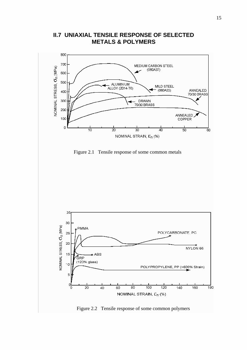
II.7 UNIAXIAL TENSILE RESPONSE OF SELECTED METALS & POLYMERS
Figure 2.1 Tensile response of some common metals
Figure 2.2 Tensile response of some common polymers

16
III. MATERIAL PROPERTY CHARTS
III.1 YOUNG’S MODULUS – DENSITY
Figure 3.1: Young’s modulus, E , against density, ρ . The design guide-lines assist in selection of materials for minimum weight, stiffness-limited design.

17
III.2 STRENGTH – DENSITY
Figure 3.2: Failure strength, fσ , against density, ρ . Failure strength is defined as the tensile
elastic limit (usually yield stress) for all materials other than ceramics, for which it is the compressive strength. The design guide-lines assist in selection of materials for minimum weight, strength-limited design.

18
III.3 YOUNG’S MODULUS – STRENGTH
Figure 3.3: Young’s modulus, E , against failure strength, fσ . Failure strength is defined as
the tensile elastic limit (usually yield stress) for all materials other than ceramics, for which it is the compressive strength. The design guide-lines assist in the selection of materials for maximum stored energy, volume-limited design.
19
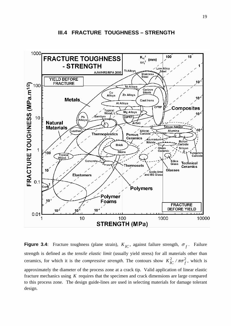
III.4 FRACTURE TOUGHNESS – STRENGTH
Figure 3.4: Fracture toughness (plane strain), ICK , against failure strength, fσ . Failure
strength is defined as the tensile elastic limit (usually yield stress) for all materials other than ceramics, for which it is the compressive strength. The contours show 22
fIC /K πσ , which is
approximately the diameter of the process zone at a crack tip. Valid application of linear elastic fracture mechanics using K requires that the specimen and crack dimensions are large compared to this process zone. The design guide-lines are used in selecting materials for damage tolerant design.

20
III.5 MAXIMUM SERVICE TEMPERATURE
Figure 3.5: Maximum service temperature. The shaded bars extend to the maximum service temperature – materials may be used safely for all temperatures up to this value, without significant property degradation. (Note: there is a modest range of maximum service temperature in a given material class – not all variants within a class may be used up to the temperature shown, so caution should be exercised if a material appears close to its limit). NB: For full names and acronyms of polymers – see Section V.

21
III.6 MATERIAL PRICE (PER KG)
Figure 3.6: Material price (per kg), mC (2003 data). mC represents raw material price/kg, and does not include manufacturing or end-of-life costs.
NB: For full names and acronyms of polymers – see Section V.

22
IV.
PR
OC
ES
S A
TTR
IBU
TE C
HA
RTS
IV.1
M
ATE
RIA
L –
PRO
CES
S C
OM
PATI
BIL
ITY
MA
TRIX
(SH
API
NG
) Fi
gure
4.1
a:
Met
als
M
etal
s
Sand Casting
Die Casting
Investment Casting
Rolling/ Forging
Extrusion
Sheet Forming
Powder Methods
Machining
Ferr
ous
Cas
t Iro
ns
M
ediu
m/H
igh
Car
bon
Ste
els
Lo
w C
arbo
n S
teel
s
Low
Allo
y/S
tain
less
Ste
els
Non
-ferr
ous
Alu
min
ium
, Cop
per,
Lead
, M
agne
sium
, Zin
c A
lloys
N
icke
l Allo
ys
Ti
tani
um A
lloys
Figu
re 4
.1b:
Po
lym
ers
and
Foam
s
Poly
mer
s
Machining
Injection Moulding
Blow Moulding
Compression Moulding
Rotational Moulding
Polymer Casting
Composite Forming
Elas
tom
ers
Th
erm
opla
stic
s
Ther
mos
ets
Poly
mer
Foa
ms
Not
es o
n ot
her m
ater
ials
:
Cer
amic
s ar
e al
l pro
cess
ed b
y po
wde
r met
hods
, and
G
lass
es a
re a
lso
mou
lded
. B
oth
are
diff
icul
t to
m
achi
ne.
Poly
mer
C
ompo
site
s ar
e sh
aped
by
de
dica
ted
form
ing
tech
niqu
es, a
nd a
re d
iffic
ult t
o m
achi
ne.
Nat
ural
Mat
eria
ls c
an o
nly
be m
achi
ned,
tho
ugh
som
e w
oods
are
als
o ho
t for
med
.

23
IV.2 MASS
Figure 4.2: Process attribute chart for shaping processes: mass range (kg)
IV.3 SECTION THICKNESS
Figure 4.3: Process attribute chart for shaping processes: section thickness (m)
Sand casting
Die casting
Investment Casting
Rolling/Forging
Extrusion
Sheet forming
Powder methods
Machining
Injection moulding
Blow moulding
Compression moulding
Rotational moulding
Polymer casting
Composite forming
10-3 10-2 0.1 1 10 102 103 104
Mass (kg)
Met
al s
hapi
ng
Cer
amic
shap
ing
Poly
mer
and
com
posi
te s
hapi
ng
Sand casting
Die casting
Investment Casting
Rolling/Forging
Extrusion
Sheet forming
Powder methods
Machining
Injection moulding
Blow moulding
Compression moulding
Rotational moulding
Polymer casting
Composite forming
10-4 10-3 10-2 0.1 1Section thickness (m)
Met
al s
hapi
ng
Cer
amic
shap
ing
Poly
mer
and
com
posi
te s
hapi
ng

24
IV.4 SURFACE ROUGHNESS
Figure 4.4: Process attribute chart for shaping processes: surface roughness (µm)
IV.5 DIMENSIONAL TOLERANCE
Figure 4.5: Process attribute chart for shaping processes: dimensional tolerance (mm)
Sand casting
Die casting
Investment Casting
Rolling/Forging
Extrusion
Sheet forming
Powder methods
Machining
Injection moulding
Blow moulding
Compression moulding
Rotational moulding
Polymer casting
Composite forming
0.1 1 10 102
Roughness (µm)
Met
al s
hapi
ng
Cer
amic
shap
ing
Poly
mer
and
com
posi
te s
hapi
ng
Sand casting
Die casting
Investment Casting
Rolling/Forging
Extrusion
Sheet forming
Powder methods
Machining
Injection moulding
Blow moulding
Compression moulding
Rotational moulding
Polymer casting
Composite forming
10-2 0.1 1 10Tolerance (mm)
Met
al s
hapi
ng
Cer
amic
shap
ing
Poly
mer
and
com
posi
te s
hapi
ng

25
IV.6 ECONOMIC BATCH SIZE
Figure 4.6: Process attribute chart for shaping processes: economic batch size
Sand casting
Die casting
Investment Casting
Rolling/Forging
Extrusion
Sheet forming
Powder methods
Machining
Injection moulding
Blow moulding
Compression moulding
Rotational moulding
Polymer casting
Composite forming
Met
al s
hapi
ng
Cer
amic
shap
ing
Poly
mer
and
com
posi
te s
hapi
ng
1 10 102 103 104 105 106 107
Economic batch size (units)
26
V.
CLA
SS
IFIC
ATI
ON
AN
D A
PP
LIC
ATI
ON
S O
F E
NG
INE
ER
ING
MA
TER
IALS
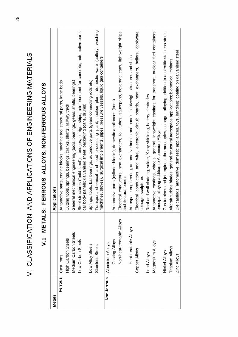
V.1
MET
ALS
: FE
RR
OU
S A
LLO
YS, N
ON
-FER
RO
US
ALL
OYS
Met
als
A
pplic
atio
ns
Ferr
ous
Cas
t Iro
ns
Aut
omot
ive
parts
, eng
ine
bloc
ks, m
achi
ne to
ol s
truct
ural
par
ts, l
athe
bed
s
Hig
h C
arbo
n S
teel
s C
uttin
g to
ols,
spr
ings
, bea
rings
, cra
nks,
sha
fts, r
ailw
ay tr
ack
M
ediu
m C
arbo
n S
teel
s G
ener
al m
echa
nica
l eng
inee
ring
(tool
s, b
earin
gs, g
ears
, sha
fts, b
earin
gs)
Lo
w C
arbo
n S
teel
s S
teel
stru
ctur
es (
“mild
ste
el”)
– b
ridge
s, o
il rig
s, s
hips
; rei
nfor
cem
ent f
or c
oncr
ete;
aut
omot
ive
parts
, ca
r bod
y pa
nels
; gal
vani
sed
shee
t; pa
ckag
ing
(can
s, d
rum
s)
Lo
w A
lloy
Ste
els
Spr
ings
, too
ls, b
all b
earin
gs, a
utom
otiv
e pa
rts (g
ears
con
nect
ing
rods
etc
)
Sta
inle
ss S
teel
s Tr
ansp
ort,
chem
ical
and
foo
d pr
oces
sing
pla
nt,
nucl
ear
plan
t, do
mes
tic w
are
(cut
lery
, w
ashi
ng
mac
hine
s, s
tove
s),
surg
ical
impl
emen
ts, p
ipes
, pre
ssur
e ve
ssel
s, li
quid
gas
con
tain
ers
Non
-ferr
ous
Alu
min
ium
Allo
ys
C
astin
g A
lloys
A
utom
otiv
e pa
rts (c
ylin
der b
lock
s), d
omes
tic a
pplia
nces
(iro
ns)
Non
-hea
t-tre
atab
le A
lloys
E
lect
rical
con
duct
ors,
hea
t ex
chan
gers
, fo
il, t
ubes
, sa
ucep
ans,
bev
erag
e ca
ns,
light
wei
ght
ship
s,
arch
itect
ural
pan
els
Hea
t-tre
atab
le A
lloys
A
eros
pace
eng
inee
ring,
aut
omot
ive
bodi
es a
nd p
anel
s, li
ghtw
eigh
t stru
ctur
es a
nd s
hips
Cop
per A
lloys
E
lect
rical
co
nduc
tors
an
d w
ire,
elec
troni
c ci
rcui
t bo
ards
, he
at
exch
ange
rs,
boile
rs,
cook
war
e,
coin
age,
scu
lptu
res
Le
ad A
lloys
R
oof a
nd w
all c
ladd
ing,
sol
der,
X-r
ay s
hiel
ding
, bat
tery
ele
ctro
des
M
agne
sium
Allo
ys
Auto
mot
ive
cast
ings
, w
heel
s, g
ener
al l
ight
wei
ght
cast
ings
for
tra
nspo
rt, n
ucle
ar f
uel
cont
aine
rs;
prin
cipa
l allo
ying
add
ition
to A
lum
iniu
m A
lloys
Nic
kel A
lloys
G
as tu
rbin
es a
nd je
t eng
ines
, the
rmoc
oupl
es, c
oina
ge;
allo
ying
add
ition
to a
uste
nitic
sta
inle
ss s
teel
s
Tita
nium
Allo
ys
Airc
raft
turb
ine
blad
es; g
ener
al s
truct
ural
aer
ospa
ce a
pplic
atio
ns; b
iom
edic
al im
plan
ts.
Zi
nc A
lloys
D
ie c
astin
gs (a
utom
otiv
e, d
omes
tic a
pplia
nces
, toy
s, h
andl
es);
coat
ing
on g
alva
nise
d st
eel

27
V.2
PO
LYM
ERS
AN
D F
OA
MS
Poly
mer
s
Abb
revi
atio
n A
pplic
atio
ns
Elas
tom
erB
utyl
Rub
ber
Ty
res,
sea
ls, a
nti-v
ibra
tion
mou
ntin
gs, e
lect
rical
insu
latio
n, tu
bing
Eth
ylen
e-vi
nyl-a
ceta
te
EV
A
Bag
s, fi
lms,
pac
kagi
ng, g
love
s, in
sula
tion,
runn
ing
shoe
s
Isop
rene
IR
Ty
res,
inne
r tub
es, i
nsul
atio
n, tu
bing
, sho
es
N
atur
al R
ubbe
r N
R
Glo
ves,
tyre
s, e
lect
rical
insu
latio
n, tu
bing
Pol
ychl
orop
rene
(Neo
pren
e)
CR
W
etsu
its, O
-rin
gs a
nd s
eals
, foo
twar
e
Pol
yure
than
e E
last
omer
s
el-P
U
Pac
kagi
ng, h
oses
, adh
esiv
es, f
abric
coa
ting
S
ilico
ne E
last
omer
s
E
lect
rical
insu
latio
n, e
lect
roni
c en
caps
ulat
ion,
med
ical
impl
ants
Th
erm
opla
stic
Acr
ylon
itrile
but
adie
ne s
tyre
ne
AB
S
Com
mun
icat
ion
appl
ianc
es, a
utom
otiv
e in
terio
rs, l
ugga
ge, t
oys,
boa
ts
C
ellu
lose
Pol
ymer
s C
A
Tool
and
cut
lery
han
dles
, dec
orat
ive
trim
, pen
s
Iono
mer
I
Pac
kagi
ng, g
olf b
alls
, blis
ter p
acks
, bot
tles
P
olya
mid
es (N
ylon
s)
PA
G
ears
, bea
rings
; plu
mbi
ng, p
acka
ging
, bot
tles,
fabr
ics,
text
iles,
rope
s
Pol
ycar
bona
te
PC
S
afet
y go
ggle
s, s
hiel
ds, h
elm
ets;
ligh
t fitt
ings
, med
ical
com
pone
nts
P
olye
ther
ethe
rket
one
P
EE
K
Ele
ctric
al c
onne
ctor
s, ra
cing
car
par
ts, f
ibre
com
posi
tes
P
olye
thyl
ene
P
E
Pac
kagi
ng, b
ags,
squ
eeze
tube
s, to
ys, a
rtific
ial j
oint
s
Pol
yeth
ylen
e te
reph
thal
ate
PE
T B
low
mou
lded
bot
tles,
film
, aud
io/v
ideo
tape
, sai
ls
P
olym
ethy
l met
hacr
ylat
e (A
cryl
ic)
PM
MA
A
ircra
ft w
indo
ws,
lens
es, r
efle
ctor
s, li
ghts
, com
pact
dis
cs
P
olyo
xym
ethy
lene
(Ace
tal)
P
OM
Zi
ps, d
omes
tic a
nd a
pplia
nce
parts
, han
dles
Pol
ypro
pyle
ne
PP
R
opes
, gar
den
furn
iture
, pip
es, k
ettle
s, e
lect
rical
insu
latio
n, a
stro
turf
P
olys
tyre
ne
PS
To
ys, p
acka
ging
, cut
lery
, aud
io c
asse
tte/C
D c
ases
Pol
yure
than
e Th
erm
opla
stic
s
tp-P
U
Cus
hion
ing,
sea
ting,
sho
e so
les,
hos
es, c
ar b
umpe
rs, i
nsul
atio
n
Pol
yvin
ylch
lorid
e P
VC
P
ipes
, gut
ters
, win
dow
fram
es, p
acka
ging
Pol
ytet
raflu
oroe
thyl
ene
(Tef
lon)
P
TFE
N
on-s
tick
coat
ings
, bea
rings
, ski
s, e
lect
rical
insu
latio
n, ta
pe
Ther
mos
etE
poxi
es
A
dhes
ives
, fib
re c
ompo
site
s, e
lect
roni
c en
caps
ulat
ion
P
heno
lics
E
lect
rical
plu
gs, s
ocke
ts, c
ookw
are,
han
dles
, adh
esiv
es
P
olye
ster
Furn
iture
, boa
ts, s
ports
goo
ds
Poly
mer
Foa
ms
Flex
ible
Pol
ymer
Foa
m
P
acka
ging
, buo
yanc
y, c
ushi
onin
g, s
pong
es, s
leep
ing
mat
s
Rig
id P
olym
er F
oam
Ther
mal
insu
latio
n, s
andw
ich
pane
ls, p
acka
ging
, buo
yanc
y

28
V.3
CO
MPO
SITE
S, C
ERA
MIC
S, G
LASS
ES A
ND
NA
TUR
AL
MA
TER
IALS
Com
posi
tes
A
pplic
atio
ns
Met
alA
lum
iniu
m/S
ilico
n C
arbi
de
Aut
omot
ive
parts
, spo
rts g
oods
Po
lym
erC
FRP
Li
ghtw
eigh
t stru
ctur
al p
arts
(aer
ospa
ce, b
ike
fram
es, s
ports
goo
ds, b
oat h
ulls
and
oar
s, s
prin
gs)
G
FRP
B
oat h
ulls
, aut
omot
ive
parts
, che
mic
al p
lant
Cer
amic
s
G
lass
esB
oros
ilica
te G
lass
O
venw
are,
labo
rato
ry w
are,
hea
dlig
hts
Gla
ss C
eram
ic
Coo
kwar
e, la
sers
, tel
esco
pe m
irror
s S
ilica
Gla
ss
Hig
h pe
rform
ance
win
dow
s, c
ruci
bles
, hig
h te
mpe
ratu
re a
pplic
atio
ns
Sod
a-Li
me
Gla
ss
Win
dow
s, b
ottle
s, tu
bing
, lig
ht b
ulbs
, pot
tery
gla
zes
Poro
usB
rick
Bui
ldin
gs
Con
cret
e G
ener
al c
ivil
engi
neer
ing
cons
truct
ion
Sto
ne
Bui
ldin
gs, a
rchi
tect
ure,
scu
lptu
re
Tech
nica
lA
lum
ina
Cut
ting
tool
s, s
park
plu
gs, m
icro
circ
uit s
ubst
rate
s, v
alve
s A
lum
iniu
m N
itrid
e M
icro
circ
uit s
ubst
rate
s an
d he
atsi
nks
Bor
on C
arbi
de
Ligh
twei
ght a
rmou
r, no
zzle
s, d
ies,
pre
cisi
on to
ol p
arts
S
ilico
n M
icro
circ
uits
, sem
icon
duct
ors,
pre
cisi
on in
stru
men
ts, I
R w
indo
ws,
ME
MS
S
ilico
n C
arbi
de
Hig
h te
mpe
ratu
re e
quip
men
t, ab
rasi
ve p
olis
hing
grit
s, b
earin
gs, a
rmou
r S
ilico
n N
itrid
e B
earin
gs, c
uttin
g to
ols,
die
s, e
ngin
e pa
rts
Tung
sten
Car
bide
C
uttin
g to
ols,
dril
ls, a
bras
ives
Nat
ural
Bam
boo
B
uild
ing,
sca
ffold
ing,
pap
er, r
opes
, bas
kets
, fur
nitu
re
C
ork
C
orks
and
bun
gs, s
eals
, flo
ats,
pac
kagi
ng, f
loor
ing
Le
athe
r
Sho
es, c
loth
ing,
bag
s, d
rive-
belts
Woo
d C
onst
ruct
ion,
floo
ring,
doo
rs, f
urni
ture
, pac
kagi
ng, s
ports
goo
ds

29
VI. EQUILIBRIUM (PHASE) DIAGRAMS
Figure 6.1 Copper – Nickel equilibrium diagram
Figure 6.2 Lead – Tin equilibrium diagram
30
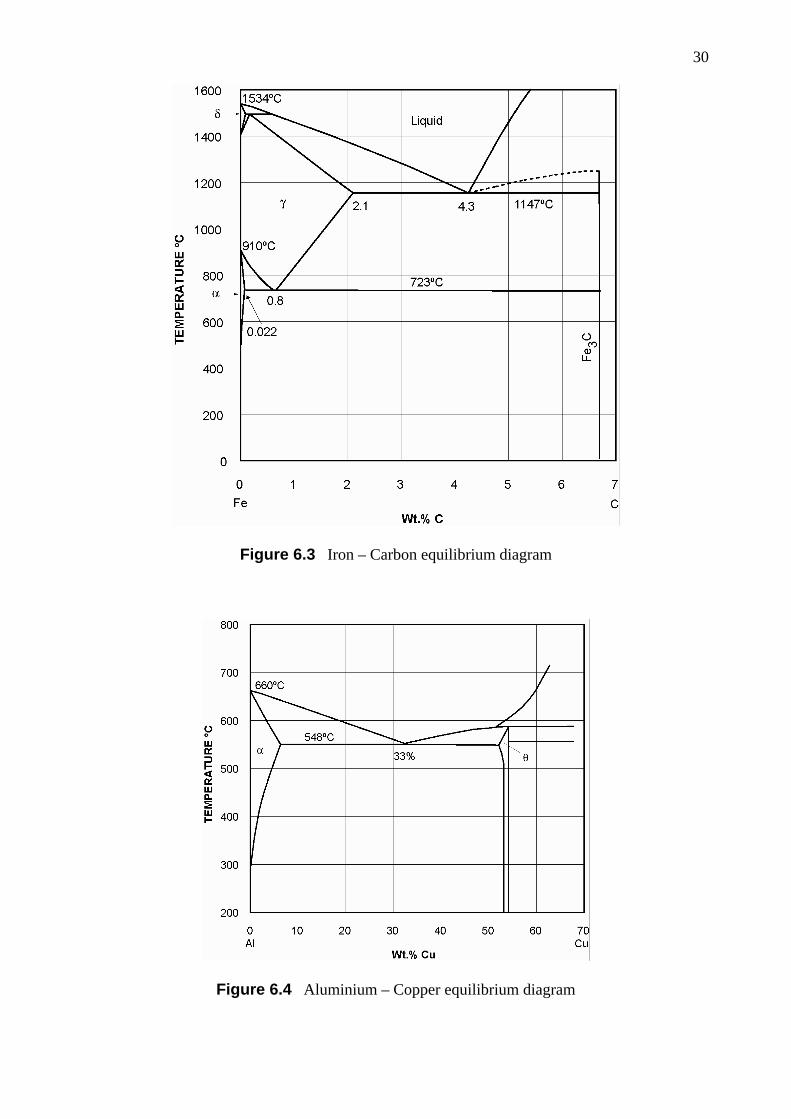
Figure 6.3 Iron – Carbon equilibrium diagram
Figure 6.4 Aluminium – Copper equilibrium diagram

31
Figure 6.5 Aluminium – Silicon equilibrium diagram
Figure 6.6 Copper – Zinc equilibrium diagram
32
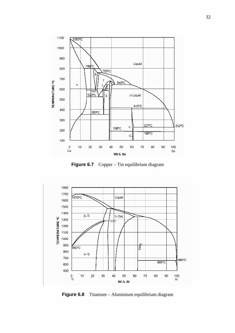
Figure 6.7 Copper – Tin equilibrium diagram
Figure 6.8 Titanium – Aluminium equilibrium diagram

33
Figure 6.9 Silica – Alumina equilibrium diagram

34
Figure 7.1 Isothermal transformation diagram for 1% nickel steel, BS503M40 (En12)
Figure 7.2 Jominy end quench curves for 1% nickel steel, BS503M40 (En12)
VII. HEAT TREATMENT OF STEELS
35
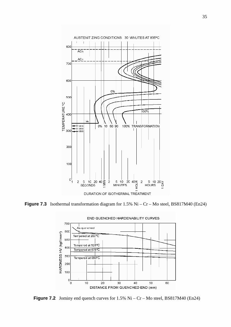
Figure 7.3 Isothermal transformation diagram for 1.5% Ni – Cr – Mo steel, BS817M40 (En24)
Figure 7.2 Jominy end quench curves for 1.5% Ni – Cr – Mo steel, BS817M40 (En24)

36
VIII. PHYSICAL PROPERTIES OF SELECTED ELEMENTS
ATOMIC PROPERTIES OF SELECTED ELEMENTS
Lattice constants 3 (at 20oC)Element Symbol Atomic Number
Relative Atomic
Weight 1
Melting Point (oC)
Crystal structure 2(at 20oC) a, (b) (Å) c (Å)
Aluminium Al 13 26.982 660 f.c.c. 4.0496 Beryllium Be 4 9.012 1280 h.c.p. 2.2856 3.5843
Boron B 5 10.811 2300 t. 8.73 5.03 Carbon C 6 12.011 3500 hex. 2.4612 6.7079 Chlorine Cl 17 35.453 – 101 – –
Chromium Cr 24 51.996 1900 b.c.c. 2.8850 Copper Cu 29 63.54 1083 f.c.c. 2.5053
Germanium Ge 32 72.59 958 d. 5.6575 Gold Au 79 196.967 1063 f.c.c. 4.0786
Hydrogen H 1 1.008 – 259 – – Iron Fe 26 55.847 1534 b.c.c. 2.8663 Lead Pb 82 207.19 327 f.c.c. 4.9505
Magnesium Mg 12 24.312 650 h.c.p. 3.2094 5.2103 Manganese Mn 25 54.938 1250 cub. 8.912 Molybdenum Mo 42 95.94 2620 b.c.c. 3.1468
Nickel Ni 28 58.71 1453 f.c.c. 3.5241 Niobium Nb 41 92.906 2420 b.c.c. 3.3007 Nitrogen N 7 14.007 – 210 – – Oxygen O 8 15.999 – 219 – –
Phosphorus P 15 30.974 44 cub. 7.17 ( at – 35oC) Silicon Si 14 28.086 1414 d. 5.4305 Silver Ag 47 107.870 961 f.c.c. 4.0862
Sulphur S 16 32.064 119 f.c.orth. 10.437, (12.845) 24.369 Tin Sn 50 118.69 232 b.c.t. 5.8313 3.1812
Titanium Ti 22 47.90 1670 h.c.p. 2.9504 4.6833 Tungsten W 74 183.85 3380 b.c.c. 3.1652 Vanadium V 23 50.942 1920 b.c.c. 3.0282
Zinc Zn 30 65.37 419 h.c.p. 2.6649 4.9468 Zirconium Zr 40 91.22 1850 h.c.p. 3.2312 5.1476
1 The values of atomic weight are those in the Report of the International Commission on
Atomic Weights (1961). The unit is 1/12th of the mass of an atom of C12. 2 f.c.c. = face-centred cubic; h.c.p. = hexagonal close-packed; b.c.c. = body-centred cubic;
t. = tetragonal; hex. = hexagonal; d. = diamond structure; cub. = cubic; f.c.orth. = face-centred orthorhombic; b.c.t. = body-centred tetragonal.
3 Lattice constants are in Ångström units (1 Å = 10–10 m)
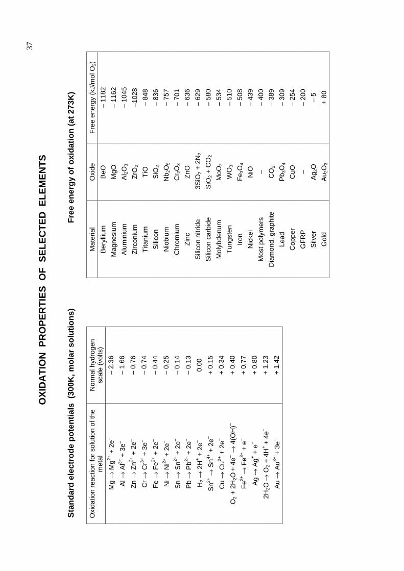
37
St
anda
rd e
lect
rode
pot
entia
ls (
300K
, mol
ar s
olut
ions
)
Oxi
datio
n re
actio
n fo
r sol
utio
n of
the
met
al
Nor
mal
hyd
roge
n sc
ale
(vol
ts)
Mg
→ M
g2+ +
2e–
– 2.
36
Al →
Al3+
+ 3
e– –
1.66
Zn →
Zn2+
+ 2
e– –
0.76
Cr →
Cr3+
+ 3
e– –
0.74
Fe →
Fe2+
+ 2
e– –
0.44
Ni →
Ni2+
+ 2
e– –
0.25
Sn
→ S
n2+ +
2e–
– 0.
14
Pb
→ P
b2+ +
2e–
– 0.
13
H2 →
2H
+ + 2
e– 0.
00
Sn2+
→ S
n4+ +
2e–
+ 0.
15
Cu
→ C
u2+ +
2e–
+ 0.
34
O2 +
2H
2O +
4e–
→ 4
(OH
)– +
0.40
Fe2+
→ F
e3+ +
e–
+ 0.
77
Ag
→ A
g+ + e
– +
0.80
2H2O
→ O
2 + 4
H+
+ 4e
– +
1.23
Au
→ A
u3+ +
3e–
+ 1.
42
Free
ene
rgy
of o
xida
tion
(at 2
73K
)
Mat
eria
l O
xide
Fr
ee e
nerg
y (k
J/m
ol O
2)
Ber
ylliu
m
BeO
–
1182
M
agne
sium
M
gO
– 11
62
Alu
min
ium
A
l 2O3
– 10
45
Zirc
oniu
m
ZrO
2 –1
028
Tita
nium
Ti
O
– 84
8 S
ilicon
S
iO2
– 83
6 N
iobi
um
Nb 2
O5
– 75
7 C
hrom
ium
C
r 2O
3 –
701
Zinc
Zn
O
– 63
6 S
ilico
n ni
tride
3
SiO
2 + 2
N2
– 62
9 S
ilico
n ca
rbid
e S
iO2 +
CO
2 –
580
Mol
ybde
num
M
oO2
– 53
4 Tu
ngst
en
WO
3 –
510
Iron
Fe3O
4 –
508
Nic
kel
NiO
–
439
Mos
t pol
ymer
s –
– 40
0 D
iam
ond,
gra
phite
C
O2
– 38
9 Le
ad
Pb 3
O4
– 30
9 C
oppe
r C
uO
– 25
4 G
FRP
–
– 20
0 S
ilver
A
g 2O
–
5 G
old
Au 2
O3
+ 80
OXI
DA
TIO
N P
RO
PER
TIES
OF
SEL
ECTE
D E
LEM
ENTS

38
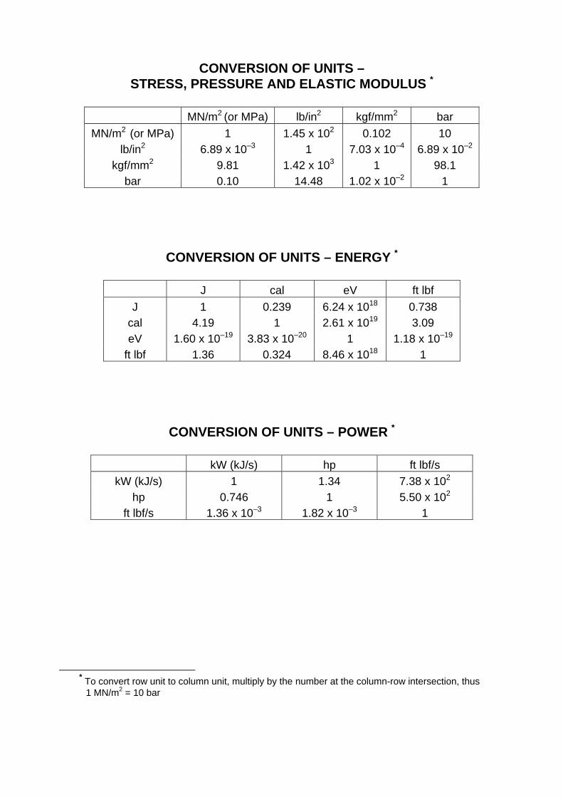
0
CONVERSION OF UNITS – STRESS, PRESSURE AND ELASTIC MODULUS *
MN/m2 (or MPa) lb/in2 kgf/mm2 bar
MN/m2 (or MPa) 1 1.45 x 10² 0.102 10 lb/in2 6.89 x 10⁻³ 1 7.03 x 10⁻⁴ 6.89 x 10⁻²
kgf/mm2 9.81 1.42 x 10³ 1 98.1 bar 0.10 14.48 1.02 x 10⁻² 1
CONVERSION OF UNITS – ENERGY *
J cal eV ft lbf J 1 0.239 6.24 x 10¹⁸ 0.738
cal 4.19 1 2.61 x 10¹⁹ 3.09 eV 1.60 x 10⁻¹⁹ 3.83 x 10⁻²⁰ 1 1.18 x 10⁻¹⁹
ft lbf 1.36 0.324 8.46 x 10¹⁸ 1
CONVERSION OF UNITS – POWER *
kW (kJ/s) hp ft lbf/s kW (kJ/s) 1 1.34 7.38 x 10²
hp 0.746 1 5.50 x 10²
ft lbf/s 1.36 x 10⁻³ 1.82 x 10⁻³ 1
* To convert row unit to column unit, multiply by the number at the column-row intersection, thus
1 MN/m2 = 10 bar