materials and processing technology area and processing technology area ... materials and process...
TRANSCRIPT

Materials and Processing Technology Area
Cliff Eberle Director,
Materials and Processing TA
January 13, 2016

2
• Carbon fibers
• Lab-scale intermediates and composites prototyping
• Recycling
• Nondestructive evaluation (NDE)
• Materials characterization
Materials and Process Technology Area Snapshot
Wide area flaw detection
Carbon Fiber Technology Facility
Polymer AM Cell
Robotic preformer
Nonwovens Research
Lab
ORNL: US leading neutron characterization and
computing power
-Thermo-plastic-glass-carbon
recycling -Factory floor NDE-Full-scale molding
with LCCF -Pultruded spar caps
-Product lifecycle modeling-Process modeling
for lab-scale validation
-Largest open access
solution spinning lab in US
-Closed loop recycling
-Factory floor NDE -Full-scale preforming-Molding
processes with LCCF
-Factory floor NDE -Full-scale
preforming and winding processes
with LCCF

3
Integration is Critical
Claus Daniel
Bob Norris
Cliff Eberle
Srdjan Simunovic
Matt WeisenbergerDoug Adams
Soydan Ozcan
DayakarPenumadu
M&P Technology Area mission is to enable technology deployment through Application Technology Areas
• M&P liaisons assigned to lead integration with other Technology Areas
• M&P leaders responsible for seamless integration within M&P Technology Area

4
Materials and Processing POC’s
Doug Adams (NDE)[email protected]
615-322.-2697
Cliff Eberle (M&P)[email protected]
865-574-0302
Soydan Ozcan (Recycling)[email protected]
865-241-2158
Dayakar PenumaduMaterials characterization
Matt WeisenbergerSolution Spinning
Uday Vaidya (CTO)[email protected]
205-410-2898
Innovations in NDE for Composites Manufacturing
Doug AdamsTech Fellow in NDE,
Daniel F. Flowers Professor,Vanderbilt University
January 13, 2016
6
What is NDE?
To see what is unseen!

7
Is this polymer uniform?
Sharp, N., Adams, D., and Caruthers, J., “Lithium-Ion Battery Electrode Inspection using Pulse Thermography,” 2014, NDT&D International, Vol. 64, pp. 41-51.
1 in
Material (% wt.) Control Test 2
LiCoO2 96 96
PVDF 2 1
Carbon Black 2 3

8
Full-Field Imaging to Diagnosis the Composite Material State In-Line
• In < 0.5 second, we can detect variations in both chemistry and geometrical flaws for use in adjusting process controls.

9
NDE Sensors Now in Reachfor Wide Scale Deployment

10
NDEPath to
InnovationIndustry Need
Inaccessible bond lineAdvanced joining concepts
Innovation
Bond, R., Underwood, S., Cummins, J., and Adams, D. E., “Structural Health Monitoring-Based Methodologies for Managing Uncertainty in Aircraft Structural Life Assessment,” Structural Health Monitoring, October 9, 2014, doi: 10.1177/1475921714553733.
u
F
Use nonlinearity to overcome barrier to inspecting large complex structures
Implementation

11
Part performance
Part frequency
QuestionWhat price will you pay for this batch
of parts?
The Cost of Composite Part Variation
Low performance dictates value

12
Combine Modeling & Simulation with NDE & Characterization for Decision Making to Enable Speed and Quality
Source Renishaw plc, New Mills, Wotton-under-Edge, Gloucestershire GL12 8JR, U.K.
Modeling & Simulation
+Characterization
Off-line NDE
M&S +
In-line NDE

13
Case Study Showing Benefits for Metals Machining Process
Source: Renishaw plc, New Mills, Wotton-under-Edge, Gloucestershire GL12 8JR, U.K.
14
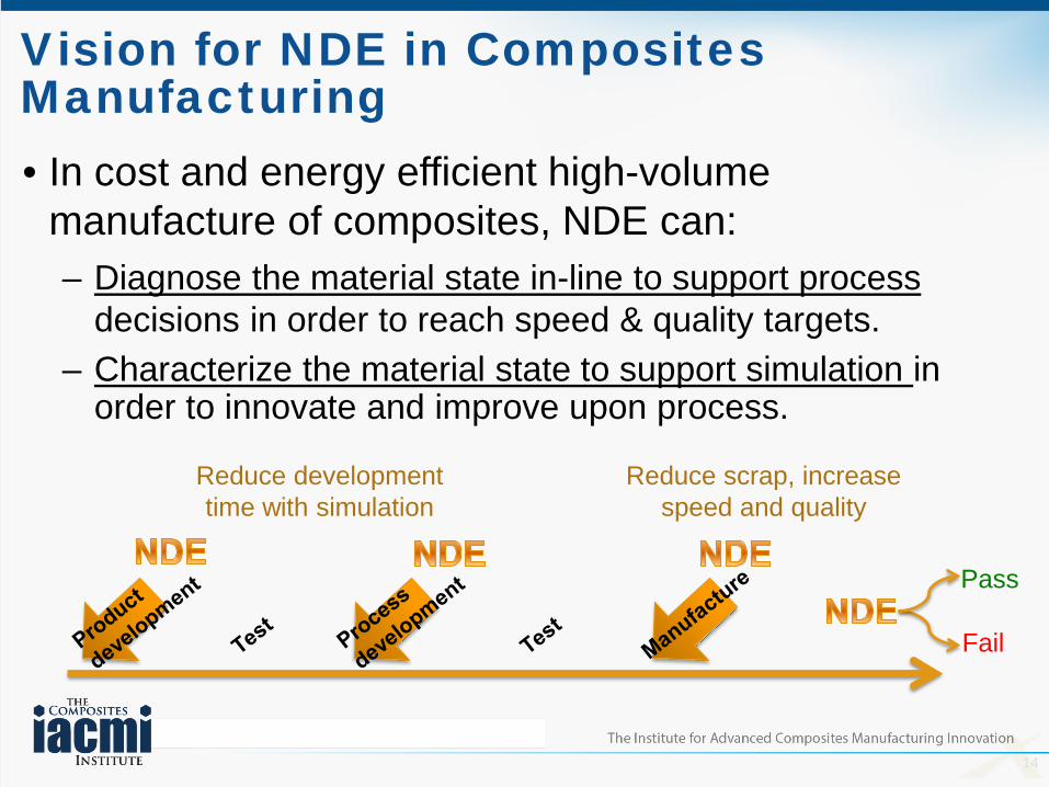
Vision for NDE in Composites Manufacturing
Reduce scrap, increasespeed and quality
Reduce developmenttime with simulation
• In cost and energy efficient high-volume manufacture of composites, NDE can:– Diagnose the material state in-line to support process
decisions in order to reach speed & quality targets.– Characterize the material state to support simulation in
order to innovate and improve upon process.
Pass
Fail

15
What it means in practice: e.g. NDE in-line diagnostics
• Processes are dynamic.
• NDE methods rely on dynamic signatures.
• So, we will use process dynamics for NDE!
Precursors
Fibers
ProductsComponents
Intermediates
Assemblies
ProcessDynamics
Resins

16
Mobile NDE Lab at Oak Ridge National Lab Carbon Fiber Technology Facility
12 tows total of 24k precursor (4 tows shown)
Precursor tow band exhibits fuzzwhich is observed with two 2D laser profilometers to render 3D tow form
17
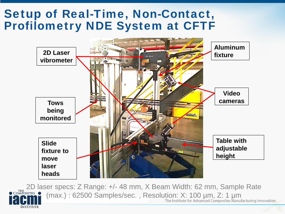
Setup of Real-Time, Non-Contact, Profilometry NDE System at CFTF
2D laser specs: Z Range: +/- 48 mm, X Beam Width: 62 mm, Sample Rate (max.) : 62500 Samples/sec. , Resolution: X: 100 µm, Z: 1 µm
2D Laser vibrometer
Tows being
monitored
Video cameras
Slide fixture to move laser heads
Table with adjustable height
Aluminum fixture

18
Profile along Tow for In-LineFuzz Detection of Precursor
Combining the 2D data through time after correlating top and bottom lasers, we can create a 3D profile.
More fuzz on this tow
Less fuzz on this tow10mm
19
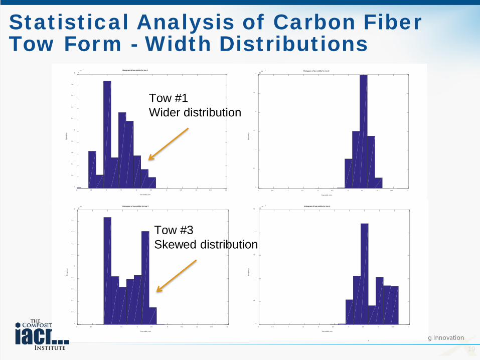
Statistical Analysis of Carbon Fiber Tow Form - Width Distributions
Tow width, mm
6 6.5 7 7.5 8 8.5 9 9.5 10 10.5 11
Freq
uenc
y
104
0
0.2
0.4
0.6
0.8
1
1.2
1.4
1.6
1.8
2
Histogram of tow widths for tow 1
Tow width, mm
6 6.5 7 7.5 8 8.5 9 9.5 10 10.5 11
Freq
uenc
y
104
0
0.5
1
1.5
2
2.5
3
Histogram of tow widths for tow 2
Tow width, mm
6 6.5 7 7.5 8 8.5 9 9.5 10 10.5 11
Freq
uenc
y
104
0
0.2
0.4
0.6
0.8
1
1.2
1.4
1.6
1.8
2
Histogram of tow widths for tow 3
Tow width, mm
6 6.5 7 7.5 8 8.5 9 9.5 10 10.5 11
Freq
uenc
y
104
0
0.5
1
1.5
2
2.5
Histogram of tow widths for tow 4
Tow #3Skewed distribution
Tow #1Wider distribution
20
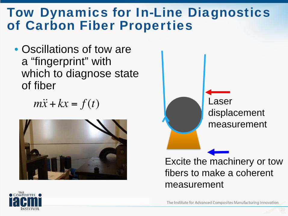
Tow Dynamics for In-Line Diagnostics of Carbon Fiber Properties
• Oscillations of tow are a “fingerprint” with which to diagnose state of fiber
Laser displacement measurement
Excite the machinery or tow fibers to make a coherent measurement

21
Change in Linear Density Detected in Carbon Fiber using Resonance
• Droplet: 0.036 grams; Tow: 0.461 grams
7 Hz

22
Similar Ideas for In-Line NDE of Material State for Composite Manufacturing
• Composites manufacturing relies on uniform flow, cure, etc.
• Variations occur in the process due to material batch and the environment, e.g., humidity.
• Improve process speed and quality using in-line NDE.
Courtesy: Wind Turbines Tech AreaDerek Berry, NREL
Infrared imaging to monitor full-field temperatureof two-part epoxy as it reaches full cure

23
What it means in practice: e.g. NDE to Support Simulation
• Processes are simulated to account for multi-physics effects on material state.
• In-process and post-process NDE can estimate material state.
• So, we will use NDE to inform simulation to close the loop around simulation models. Courtesy: Design, Modeling and Simulation Tech Area
R. Byron Pipes, Purdue University

24
NDE Overview• Use NDE data to help
meet IACMI metrics for speed and quality by closing the loop around process design and control.
• Deploy technology across supply chain through a mobile NDE lab.
Precursors
Fibers
Process monitoringof material state
Process Quality ControlProperty Quality AssuranceProduct Lifecycle Support
Products
Healthmonitoring
Flaw imaging
Components
Intermediates
Microstructureimaging
Assemblies
Rapid inspection
Pass
25
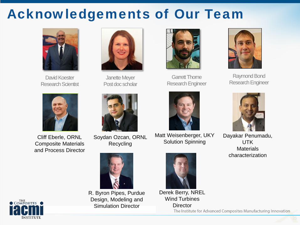
Acknowledgements of Our Team
David KoesterResearch Scientist
Janette MeyerPost doc scholar
Garrett ThorneResearch Engineer
Cliff Eberle, ORNLComposite Materials and Process Director
Soydan Ozcan, ORNL Recycling
Dayakar Penumadu, UTK
Materials characterization
Matt Weisenberger, UKYSolution Spinning
Raymond BondResearch Engineer
R. Byron Pipes, PurdueDesign, Modeling and
Simulation Director
Derek Berry, NRELWind Turbines
Director

26
Acknowledgements of Our Team
Carbon Fiber Technology Facility StaffOak Ridge National Laboratory

Innovations in NDE for Composites Manufacturing
Doug AdamsTech Fellow in NDE,
Daniel F. Flowers Professor,Vanderbilt University
January 13, 2016