materials analysis of the titan-i reversed-field-pinch
TRANSCRIPT

Fusion Engineering and Design 23 (1993) 99-113 99 North-Holland
Materials analysis of the TITAN-I reversed-field-pinch fusion power core
S h a h r a m S h a r a f a t a, N a s r M. G h o n i e m a, Pa t r i ck I .H. C o o k e a,l R o d g e r C. M a r t i n a,2,
F a r r o k h N a j m a b a d i a, K e n n e t h R. Schu l t z b, C l e m e n t P.C. W o n g b and the T I T A N T e a m *
o Institute of Plasma and Fusion Research, University of California, Los Angeles, CA 90024-1597, USA h General Atomics, San Diego, CA 92186, USA
The operating conditions of a compact, high-neutron-wall-loading fusion reactor severely limit the choices for structural, shield, insulator, and breeder materials. In particular the response of plasma-facing materials to radiation, thermal and pressure stresses, and their compatibility with coolants are of primary concern. Material selection issues are investigated for the compact, high mass-power-density TITAN-I reactor design study. In this paper the major findings regarding material performance are discussed. The retention of mechanical strength at relatively high temperatures, low thermal stresses, and compatibility with liquid lithium make vanadium-base alloys a promising material for structural components. Based on limited data, the thermal creep behaviour of V-3Ti-ISi and V-15Cr-5Ti alloys is approximated using the modified minimum committment method. In addition, the effects of irradiation and helium generation are superimposed on the creep behavior of V-3Ti-ISi. Coolant compatibility issues are investigated. The liquid lithium compatibility of the two vanadium alloys, V-15Cr-5Ti and V-3Ti-ISi , are compared, and the latter was chosen as the primary structural-material candidate for the liquid-lithium-cooled TITAN-I reactor. Electrically insulating materials, capable of operating at high temperatures are necessary throughout the fusion reactor device. Electrical insulator-material issues of concern include irradiation induced swelling and conductivity. Both issues are investigated and operating temperatures for minimum swelling and dielectric breakdown strength are identified for spinel (MgAIzO4).
1. Introduction
The T ITAN-I reactor is a compact, high-power- density reactor (major radius 3.9 m, plasma minor radius 0.6 m, neutron wall loading 18 M W / m 2 ) , based on the reversed-field-pinch (RFP) confinement con- cept. The T ITAN-I fusion power core (FPC) is cooled by liquid lithium and uses a vanadium alloy ( V - 3 T i - 1Si) as the structural material. An overview of the T ITAN-I design is given in this volume [1].
The attractiveness of commercial fusion power de- vices depends to a large extent on material perfor- mance. Components of a fusion reactor are exposed to a unique set of stress, thermal, radiation, electromag- netic, and chemical loads and should function properly
for the duration of the design lifetime. Material op- tions are even more limited for a compact, high- power-density reactor such as T I T A N because of high heat and irradiation fluxes. Safety and waste-manage- ment criteria further restrict material options; the goal of the T I T A N reactor study has been to satisfy Class-C waste disposal criteria and achieve a Level-2 of safety assurance [1].
This paper describes materials selection criteria and material issues for the T ITAN-I reactor design. Sec- tion 2 covers structural materials aspects and the ef- fects of irradiation on material properties. Compatibil- ity of liquid lithium with the structural material is discussed in Section 3. In Section 4 options for electri- cal insulator materials are presented. Results are sum- marized in Section 5.
Present addresses: On assignment from Culham Laboratory, Abington, Oxford- shire, UK,
2 Oak Ridge National Laboratory, Oak Ridge, TN 37831, USA.
* See p. 69 in this issue.
2. Structural material
For fusion reactor structural materials, the advan- tages of vanadium-base alloys over other alloys has
0 9 2 0 - 3 7 9 6 / 9 3 / $ 0 6 . 0 0 © 1993 - E l s e v i e r S c i e n c e P u b l i s h e r s B.V. A l l r igh ts r e s e r v e d

100 S. Sharafat et al. / Materials analysis
been pointed out in previous publications [2,3]. In particular, when compared with ferritic-steel alloys, vanadium-base alloys exhibit better physical, mechani- cal, and nuclear properties. For example, compared to HT-9, vanadium-base alloys have a higher melting tem- perature, a lower thermal expansion coefficient, and a lower density. At 1 M W / m 2 of neutron wall load, vanadium-base alloys have about half the nuclear heat- ing rate (i.e., ~ 25 W/cm3), about a third of the helium generation rate (i.e., ~ 57 He appm), about half the hydrogen production rate (i.e., ~ 240 H appm/MW y/m2), and lower longterm afterheat when compared to ferritic alloys [2].
The high melting temperature of vanadium alloys (T m = 1890°C) has significant bearing on safety related issues. The higher ultimate tensile strength (o- u ~ 600 MPa at 600°C), the lower expansion coefficient, and thc slightly higher thermal conductivity of vanadium- base alloys are reflected in a higher thermal stress factor when compared to HT-9 [2]. The thermal stress factor is a measure of heat load capability. The high T m, coupled with a high thermal stress factor, and the favorable nuclear properties promise a high operating temperature and a high-neutron-wall-loading capabil- ity. Table 1 shows selected properties of vanadium-base alloys.
Among the various vanadium-base alloys, the most promising candidates for fusion reactor applications are V-15Cr-5Ti, VANSTAR-7 (V-9Cr -3Fe - IZr ) , and V-3Ti - IS i . The V-3T i - IS i alloy was chosen as the structural material for TITAN-I based on its radia- tion damage response behavior. The choice was made based on the data available at the time of the study. Current and future alloy development efforts may re- sult in other radiation damage resistant vanadium-base alloy.
Previously, the V-15Cr-5Ti alloy has received con- siderable attention [3]. Although V-15Cr-5Ti has a higher thermal-creep resistance than the other two vanadium-base alloys, recent investigations [4] of the effects of neutron irradiation with pre-implanted he- lium atoms suggests that V-15Cr-5Ti may be subject to unacceptable losses in ductility. Braski [4] irradiated specimens of V-15Cr-5Ti, V-3Ti - IS i , and VAN- STAR-7 at 420, 520, and 600°C to a damage level of 40 dpa with implanted helium atoms up to a concentra- tion of 80 appm. Tensile tests showed that helium pre-implanted V-15Cr-5Ti had zero ductility in ten- sion after irradiation at 600°C. Under the same condi- tions, VANSTAR-7 and V-3Ti - IS i retained uniform elongations of about 3.3% and 8.3%, respectively. Fig- ure 1 shows the stress-strain behavior of the candidate
Table 1 Physical properties of vanadium-base V-3Ti-ISi)
alloys [2] (adopted for
Atomic weight Density t~ Crystal structure Melting temperature Boiling temperature Heat of fusion Heat of vaporization Heat capacity
at 400°C at 500°C
at 600°C Thermal conductivity
at 400°C at 500°C at 600°C
Coefficient of thermal expansion at 400°C at 500°C at 600°C
Electrical resistivity at 400°C at 500°C at 600°C
Poisson ratio Young's modulus
50.9 6100 kg/m 3 b.c.c. 1890°C 3400°C 143 kJ/kg 2265 kJ/kg
535 J/kg-K 560 J/kg-K 575 J/kg-K
26.8 W/m-K 28.0 W/m-K 29.5 W/m-K
10.2 × 10 - 6 / K 10.3 x 10 - 6 / K 10.5 × 10 - 6 / K
0.67,0./2m 0.74/.tOm 0.81 ~.Om 0.36 127 GPa
(a) Properties are at room temperature.
vanadium-base alloys before and after irradiation. These measurements indicate that V-3T i - IS i suffers the least amount of irradiation hardening and helium embrittlement.
The fundamental aspects of selecting the V - 3 T i - I S i alloy based on hydrogen embrittlement, helium embrit- tlement, radiation hardening, swelling, and creep rates are discussed in Section 2.1. Creep behavior and re- crystallization behavior of vanadium-base alloys is out- lined in Section 2.2. The allowable design stresses including some of the radiation effects are discussed in Section 2.3.
2.1. Radiation damage response
The effects of radiation damage on the operating conditions of metallic structural materials can be di- vided into four categories: (1) increase in ductile-to- brittle transition temperature (DBTF) with neutron damage, (2) irradiation-induced dimensional changes such as swelling and creep, (3) mechanical property
, changes such as tensile strength and toughness (irradi- ation hardening), and (4) helium and hydrogen embrit-

S. Sharafat et al. / Materials analysis 101
tlement. Based on these effects, a lifetime damage dose limit of about 200 displacements per atom (dpa), (which corresponds to neutron exposure of ~ 15 to 20 MW y / m 2) is generally quoted as the limit for most ferrous alloys. Because of limited data on vanadium- base alloys, this damage limit range of 15 to 18 MW y / m 2 is adopted for the TITAN-I design. The lifetime-limiting processes are discussed in this section.
Ductile to brittle transition temperature Loomis and Carlson [5] have reported that hydro-
gen concentrations above 5000 appm are required to raise the ductile-to-brittle transition temperature (DB'I-T) of vanadium above room temperature. Hydro- gen and helium production rates were estimated for the V-3Ti - IS i TITAN-I first wall to be about 5400 and 1200 appm/y (atomic parts per million/y) respec- tively. The hydrogen production rate in the TITAN-I first wall is slightly above the 5000 appm necessary to
O._
800
600
400
200
I I I I I I I
(A)
V-15Cr-5Ti
~ -1S i
7 . . . . . . . . . . . i, 2 6 10 14 18 22 26
O..
cO
1000
800
600
400
200
0 - 2
V-15Cr-5Ti (T=520 C, He=74 appm) (~).
VANSTAR-7 (T=600 C, He=70 appm)
~ ~ - ~ V - 3 " l ' i - 1 Si (T=600 C, He=82 appm)
I i I I I I i I
2 6 10 14 18 22 26
Strain (%)
Fig. l. Stress-strain behavior of three unirradiated (A) and irradiated (B) candidate vanadium-base alloys [4].
Table 2 Swelling A V / V (%), of three vanadium-base alloys [4] ~")
Alloy 420°C 520°C 620°C
V-3Ti- 1Si 0.09 0.002 0.05 VANSTAR-7 0.004 6.0 0.06 V- 15Cr-5Ti 0.005 0.005 0.3
(a) Irradiated to 40 dpa with a He content of ~ 80 appm.
cause an increase in the DBTT following one full-power year (FPY) of operation. However, vanadium forms stable hydrides only at relatively low temperatures (< 400°C). When the structure is kept at temperatures above 400°C, most of the hydrogen migrates down the temperature gradient towards the coolant. The TI- TAN-I first wall operates at around 700°C, which is well above the hydrogen solubility limit of 400°C. It should be noted that in addition to transmutations, tritium will also penetrate the first wall from the plasma side. Aspects of plasma-driven tritium permeation through the first wall are discussed in this volume [6].
The change in DBTT of vanadium-base alloys is expected to be negligible at high operating tempera- tures (>_ 600°C). This expectation is also based on the operating experience with ferritic alloys, which have the same crystal structure (b.c.c.) as that of vanadium- base alloys.
Swelling The primary cause of swelling in metallic alloys can
be contributed to the presence of transmutation pro- duced helium atoms inside the crystals. Table 2 shows the swelling results of the three vanadium-base alloy samples with pre-implanted helium. The data, al- though limited, indicate that the V-3Ti - IS i alloy has the lowest swelling rates at temperatures above 500°C after 40 dpa of damage. Using the above test data and assuming a linear swelling behavior, the maximum swelling (zaV/V) of the TITAN-I first wall would be ~ 0.2% after 1 FPY of operation (164 dpa). Thus, a reasonable extrapolation of Braski's results [4] indi- cates that neutron-radiation-induced swelling of V- 3Ti- lSi could be negligible. Thus, neither a change in the DBTT nor irradiation-induced swelling would limit the lifetime of the TITAN-I design below 15 to 18 MW y / m 2.
Irradiation hardening Neutron irradiation of metallic alloys can result in
the formation and growth of new dislocation networks, resulting in an increased yield strength and decreased ductility (irradiation hardening). Figure 2 illustrates

102 S. Sharafat et aL / Materials analysis
800 I I I I I I I ~ , ~ VANSTAR-7 13_
~, V-15Cr-5Ti
Z 400 Z UJ I--oZ-l- <rr't'~ 200 ~ ~ ~ V - 3 T i - l S i
< a <- 0 -I-2°Ti'~~/"~[ ~'~'~ n" F Ell R I T 4 1 ~ . , , ~ . , . ~ / / x ~ ,
-200 300 400 500 600 700
IRRADIATION TEST TEMPERATURE (°C) Fig. 2. ]rradiation hardening as a function of irradiation test temperature for vanadium alloys compared with similar data
for austenitic and ferritic stainless steels [4].
the irradiation hardening behavior of various metallic alloys. In general, V-20Ti, V-3Ti- ISi , and ferritic alloys exhibit radiation hardening below 500°C. Above 500°C, irradiation hardening anneals out and mechani- cal properties are no longer affected significantly. Al- though irradiation data of V-3Ti - IS i is limited, irradi- ation hardening is not considered a major lifetime- limiting phenomena for this alloy, based on the TI- TAN-I high operating temperature.
Helium and hydrogen embrittlement The most severe lifetime-limiting effect is believed
to be caused by neutron-generated helium atoms inside the bulk material. Helium atoms are trapped inside the matrix at trapping sites, such as dislocations, voids, and precipitates. As more and more helium is generated during operation, the helium bubbles grow and cause changes in the mechanical property of the material. The most pronounced effect is a degradation of ductil- ity generally known as helium embrittlement.
The amount of helium generated during operation in the TITAN-I first wall is estimated to be ~ 1200 appm/y at 18 MW y / m 2. The effect of helium genera- tion in the first wall was included in the creep analysis, as described in the following section. Based on these calculations, the maximum operating temperatures and
stresses were estimated for end-of-life operating condi- tions.
Hydrogen embrittlement in the TITAN-I first wall is assumed to be small because of the following three factors: (1) the high operating temperature (~ 700°C) does not allow the formation of stable vanadium hy- drides, (2) the diffusion of hydrogen through vanadium is rapid at these temperatures, resulting in low levels of dissolved-hydrogen concentrations, and (3) the maxi- mum amount of hydrogen produced during one FPY is estimated between 5,000 to 6,000 appm, which is roughly the solubility limit of hydrogen in vanadium. Based on these observations, hydrogen production in the vanadium-base-alloy TITAN-I structural material is not considered a lifetime-limiting factor.
Because of the incomplete data base on vanadium- base alloys, a lifetime limit range between 15 and 18 MW y / m 2 is used for the TITAN-I design, which is similar to the generally quoted value for most ferrous alloys. Analysis of the lifetime-limiting processes for the TITAN-I design indicates that this value is reason- able. However, it should be noted that many effects, particularly the synergism of radiation damage and helium production, can not be modeled because of lack of data. Furthermore, a more rigorous lifetime analysis would include fatigue and thermal shock responses of the material. The limited data base on vanadium-base alloys does not warrant such a detailed analysis; more experimental data on vanadium-base alloys are needed.
Because the above test data show that V-3Ti - IS i has the lowest swelling, irradiation hardening, and helium embrittlement rates, this alloy was chosen as the primary structural material for the TITAN-I reac- tor design.
2.2. Creep behavior and recrystallization
Creep may be defined as the time-dependent defor- mation of the material under an applied load. Creep is a complex mechanism that depends on stress, strain, time, temperature, and microstructure. In a radiation environment, microstructural changes are generally ac- celerated, and drastic effects on the creep behavior of metals can be expected. Many mechanisms which may cause creep have been identified, such as dislocation creep, diffusion creep, grain-boundary sliding, and irra- diation creep. Except for the irradiation creep mecha- nism, the others involve deformation of the solid by overcoming internal barriers caused by the thermal activation or applied stresses. Irradiation creep in- volves the production of internal stresses which are

S. Sharafat et al. / Materials analysis 103
greater than the external stresses because of irradia- t ion-induced microstructural changes. The material then creeps under the influence of this internal stress. Because of the complexity of creep deformation, de- signers rely heavily on empirical equations to predict creep deformation. For vanadium-base alloys, the ex- pected service life is much longer than the duration for which experimental creep data are available. Extrapo- lation of the creep data, in particular the creep-rupture data, to longer times has been studied extensively over the past decades [7-9].
Widely used extrapolation techniques for creep-rup- ture data include the Larson-Miller, White-LeMay, and Orr-Sherby-Dorn methods [7]. These methods pre- dict the value of the rupture time (t r) as a function of the material temperature and for different applied stresses. The choice and success of these methods depends on the behavior of the creep-rupture data and assumed pattern for the data in each method. As a result, it is possible for these methods to predict very different values of stresses appropriate to long-life conditions [7]. To overcome this problem, the mini- mum-commitment method (MCM) was developed at N A S A [8] to extrapolate creep-rupture data, without forcing the creep data to any specific pattern. Ghoniem et al. [9] developed a modif ied-minimum-commitment method (MMCM) in which the stress, the time to rupture, and the temperature are related by the follow- ing functional form:
In(o-r) = A ( T ) + B ( T ) In( t r ) , (1)
where err is the stress to rupture in MPa, t r is the time to rupture in hours, and A(T) and B(T) are tempera- ture-dependent parameters given by:
A ( T ) = a o + a l T and B ( T ) = b o + b i T . (2)
The temperature (T) is in Kelvin and a 0, a~, b o, and b~ are constants determined by fitting creep-rupture data. The coefficients of eq. (2) for V - 3 T i - I S i and V - 1 5 C r - 5 T i are given in Table 3.
Creep-rupture stress data for vanadium alloys, in particular V - 3 T i - I S i , is very limited. Some V - 3 T i - I S i
Table 3 Coefficients for the creep-rupture stress equation
Coefficient V-3Ti-ISi V-15Cr-5Ti
a o 9.507209 7.239522 a t -3.50498 x 10 -3 - 1.04844 x 10 -3 b o 4.85748x10 x 2.17853x10 -~- b t - 6.07858 x 10 -4 - 7.38258 x l0 -5
Creep-Rupture Time of V-3Ti-ISi (Minimum-Commitment Method)
10 ~
O ~ 650"C
10' ~ ~ 9so'c
. . . . . to o.
IO ° ~ 10 ° 10' 10 3 10 3 10' l0 s 0'
Time-to-Rupture (h) Fig. 3. Creep-rupture stresses of V-3Ti-ISi at various tem- peratures. Symbols are creep-rupture data points [10] and solid lines are estimates using MNCM [9]. Also shown are the expected stress ranges during normal and off-normal opera-
tions of the TITAN-I design.
creep-rupture stress data [10] are available at 750 and 850°C. At 650°C, data were found only for a V - 3 T i alloy containing unspecified amounts of silicon. The creep-rupture data at these three temperatures is used to develop a phenomenological stress-rupture equation (similar to eq. (1)). A similar equation was also devel- oped for V - 1 5 C r - 5 T i using more recent creep-rupture data [11].
Figure 3 shows the experimental data points [10] and M M C M calculational results (lines) for the creep- rupture stress of V - 3 T i - I S i at several temperatures, as well as the expected stress range in the first wall of T ITAN- I during normal and off-normal operation. Based on the results of the M M C M extrapolation equation, operat ion of the first wall at a pressure close to 100 MPa and at temperatures below 700°C will not lead to creep rupture within one year of normal opera- tion. During off-normal conditions, coolant pressure is lost and creep rupture would not occur even if the structure were kept at elevated temperatures (1000°C) for a prolonged period of time. However, high-temper- ature (850°C) creep-rupture data are necessary to gain

104 S. Sharafat et al. / Materials analysis
more confidence in the creep-rupture behavior at these higher temperatures.
Recovery of dislocations in vanadium-base alloys starts at ~ 800°C. Above 900°C, recrystallization (re- Helium alignment of grain boundaries) sets in and around 1000 (appm) to l l00°C grain growth begins. For design purposes, measurements of the 50% recrystallization tempera- 0
10 tures are necessary (50% recrystallization temperature is the temperature at which 50% of the base material is 150
300 completely recrystallized during a specified holding 490 time). Because of the lack of data on these high-tem- perature processes, the predicted high-temperature ( > 900°C) creep behavior of V - 3 T i - I S i is highly uncer- tain. Also, irradiation may enhance the thermal-creep component, but for lack of any data this enhancement is treated approximately, as is discussed in the follow- ing section.
2.3. Allowable design stresses
The design of structural components under high loads is based on specifications of the A S M E Code Case 1592 for Class 1 Components in Elevated-Tem- perature Service [12]. Different allowable stresses for various stress classifications are assigned by specifying stress-intensity values for t ime-independent allowable stress (Sin), t ime-dependent allowable stress (St), or general primary membrane allowable stress (Smt) which is taken as the lesser of S m and S t. The S t is the lowest value of 2 / 3 of the minimum stress to cause rupture after time t, or 80% of minimum stress to cause tertiary creep after time t, or the minimum stress to produce 1% strain at time t. For the V - 3 T i - I S i alloy, the creep-behavior data is too limited to base the maximum allowable stress on the 1% strain or on the tertiary-creep criteria. Therefore, the maximum allow- able stresses in structural components made of V - 3 T i - 1Si was set at 2 / 3 of the minimum stress to cause rupture.
In establishing allowable design stresses an effort was made to allow for irradiation-induced loss of duc- tility (irradiation hardening and helium embritt lement). To incorporate these effects, a simple creep-rate equa- tion of the form
= Kcr" (3)
was assumed. Here, ~ is the creep rate, K is a con- stant, o- is the applied stress, and n is the creep exponent. Using eq. (3), the irradiated and unirradi- ated creep behavior are related through
- - = ( 4 ) E
Table 4 Elongation of three vanadium-base alloys as a function of helium content at 600°C [13]
Elongation (%)
V-3Ti- 1Si V- 15Cr-5Ti VANSTAR-7
22 30 35 16 12 35 14 8 - 11 0 - 7 - -
or solving for the stress of irradiated material, Orirr,
~i.-- '~ (5)
Here, Eir r and E are the creep-rupture strain of irradi- ated and unirradiated material, respectively. Gold et al. [11] reported values for the creep exponent ranging from 2 to 10 for V - 3 T i - I S i alloys. For our estimates, a value of 4 is used for the creep exponent. This choice is based on experience with creep exponent values for other b.c.c structured alloys [9].
Braski [13] measured the total elongation of V - 3T i - lS i , V - 1 5 C r - 5 T i , and V A N S T A R - 7 as a function of implanted hel ium-atom content of up to 500 appm at 600°C. Table 4 shows the total elongation as a function of helium content for three vanadium-base alloys. The helium embri t t lement behavior of V - 3 T i - 1Si was extrapolated beyond the available 500-appm data. Next, the helium embri t t lement data of Table 4 was used to approximate the ratio of eirr/¢ as a func- tion of helium content (or irradiation time). Equat ion (5) was then used to modify the unirradiated stress-to- rupture values calculated previously as a function of time and temperature. Figure 4 shows the calculated creep-rupture stresses as a function of time using this approach.
By taking S t to be 2 / 3 the minimum stress to cause creep rupture, the maximum allowable design stress was estimated. Table 5 shows the values of S t at 650, 750, and 850°C for the T ITAN-I first wall. It should be emphasized that because of lack of higher temperature data, the S t values are all based on helium embritt le- ment data measured at 600°C.
3. C o o l a n t c o m p a t i b i l i t y
The primary coolant of the T ITAN-I FPC is liquid lithium. Liquid lithium, which also acts as the breeding

S. Sharafat et al. / Materials analysis 105
10 3
C r e e p - R u p t u r e T i m e o f V - 3 T i - I S i ( E f f e c t o f I r r a d i a t i o n H a r d e n i n g )
10 2 c0 c One Year
10' 10 ° 10 ' 10 ' 10 ' 10 ' 10 5 0 '
T i m e - t o - R u p t u r e (h) Fig. 4. Creep-rupture stress curves for V-3Ti-ISi at various temperatures estimated by MMCM [9]. Solid lines represent the creep behavior of unirradiated and dashed lines that of irradiated V-3Ti-ISi alloy. Also shown is the expected stress
range during the normal operation of the TITAN-I design.
material, has a low melting temperature, low density, and good thermal characteristics.
As an alkali metal, lithium requires careful handling because of its reactivity with water and atmospheric constituents (e.g., oxygen, nitrogen, hydrogen, and car- bon dioxide). Because lithium will readily react with water to form gaseous hydrogen and heat, hydrogen explosions are one of the serious threats. Compared to sodium, however, lithium reacts much less vigorously with water [14]. Lithium also has a higher melting point, specific heat, and heat of fusion than sodium.
Table 5 Maximum allowable design stresses for the TITAN-I first wall (a)
T (°C) ~ (MPa)
650 115 750 47 850 19
ta~ Based on 2/3 of irradiated creep-rupture stresses after one FPY of operation at 18 MW/m 2.
Because of the experience of the fission industry with molten sodium (specifically in liquid-metal fast-breeder reactors), handling large amounts of liquid lithium should not pose a serious technological problem. Lithium is used in many areas of medicine and elec- tronics. Therefore, a nearly complete set of properties is available [14].
In this work the compatibility of liquid lithium with the structural material is addressed. Attack by pure liquid metals differs from that of other corrosives since there is usually no chemical reaction involved. The rate of attack depends primarily on the solubility of the solid metal in the liquid metal and the solution rate. Chemical reactions become important only when impu- rities such as oxygen, nitrogen, and carbon are present. These attack mechanisms are discussed to establish the degree of compatibility between liquid lithium and vanadium-base alloys, particularly V-3Ti- ISi . The im- pact of high velocity coolant is also considered.
3.1. Lithium attack
Structural materials in contact with liquid metals can experience some form of attack. The following types of liquid-metal attack are discussed briefly:
• Simple solution; • Liquid-metal penetration; • Temperature-gradient mass transfer; • Liquid-metal embrittlement; • Dissimilar-metal mass transfer; • Impurity reactions (oxygen, nitrogen, carbon, hy-
drogen).
Simple solution attack In simple solution attack, solid metal dissolves in
the liquid metal to the extent of its solubility. It can result in uniform thinning of the material or cause intergranular penetration if a single constituent is pref- erentially leached from the solid. During the late 1950s and early 1960s, forced-circulation-loop tests with vanadium and liquid lithium were conducted as part of the space-power program [15]. Tests were run with unalloyed vanadium for up to 1170 hours. The lithium flow velocity was 4 m / s with a maximum temperature of 870°C. Reported corrosion rates for vanadium were nil. The BCSS [3] interpreted the reported value as ~ 0.1 ~m/ y , based on a reported minimum corrosion rates of other alloys [3]. Capsule tests conducted at ORNL [16] and forced-circulation tests at Argonne National Laboratory [17] later confirmed the corrosion resistance of vanadium-base alloys to liquid lithium. Although the solubility of vanadium in lithium was not

106 S. Sharafat et al. / Materials analysis
reported, these results indicate negligible vanadium solubility.
Liquid-metal penetration The presence of impurities such as oxygen, carbon,
and nitrogen in solid metals has been found to influ- ence the compatibility of alloys with liquid alkali met- als [18]. Liquid-metal penetration (LMP) has been ob- served to occur when the solid metal contains more than a certain threshold impurity concentration [18-20]. Rapid penetration along grain boundaries can occur. While vanadium was found not to be susceptible to LMP, a l-mm specimen of tantalum containing 600 appm of oxygen was completely penetrated by lithium after exposure for 0.5 h at 600°C [20]. This penetration phenomenon has been found in a number of refractory metals exposed to lithium, sodium, potassium, and the sodium-potassium eutectic, NaK [20-22]. In conjunc- tion with corrosion, transgranular penetration of vana- dium-base alloys by liquid lithium has been investi- gated during the capsule tests performed at ORNL [16]. It was found that. unlike niobium and tantalum, vanadium did not suffer from any severe penetration rate regardless of whether oxygen was present or not [3].
Temperature-gradient mass transfer The low solubility of structural materials in the
coolants makes simple solution of most metals negligi- ble. However, when a temperature gradient exists, such as in a coolant loop, the solid metal approaches satura- tion in the hotter zone only to crystallize out in the cooler regions because of the decrease in solubility. This effect sets up temperature-gradient mass-transfer mechanism that can ultimately result in tube plugging in the cold leg of a coolant loop.
Because of the low corrosion rates of vanadium-base alloys (< 0.1 /.Lm/y at 860°C [15]), the transport of structural material from high-temperature regions and consequent deposition at the cold leg of the primary loop does not seem to be a major concern, even by fission-industry guidelines [3]. However, an additional complication may arise from the presence of strongly varying magnetic fields which can impact the deposi- tion of ferromagnetic substances.
Liquid-metal embrittlement Liquid-metal embrittlement is caused by a reduc-
tion in bond strength of the atoms in a solid by chemisorption of a liquid atom at the tip of a crack or at the end of a pileup of dislocations near a surface obstacle. Attachment of an impurity atom reduces the stress required for cleavage. Thus, normally ductile
materials may fail in a brittlc manner by cleavage or by rapid intergranular crack propagation [23]. Ammon [18] reported that vanadium-base alloys are not suscep- tible to liquid-metal embrittlement by lithium.
Dissimilar-metal mass transfer Since vanadium is an expensive material, it would
be advantageous to use steels as the structural material of the primary-loop piping outside the FPC where the structural material is not subjected to extreme radia- tion and heat loads. When dissimilar metals are in contact with the same liquid metal, one of the metals may be transferred through the liquid metal to alloy with the other metal. Removal of the soluble metal from solution by this method ensures that saturation is never attained. This can lead to unacceptably high levels of corrosion even when the solubility of a metal in the liquid metal is very low. An example of this rapid attack is the rapid dissolution of SS-304 stainless steel by molten lithium in an iron container [24,25]. However, vanadium-steel bimetallic-loop tests have not reported a significant dissimilar-metal transfer problem [26,27].
Impurity reactions Another effect of having dissimilar metals in con-
tact with the same liquid metal is the transfer of nonmetallic constituents between the alloys. This pro- cess is generally referred to as the bimetallic impurity pickup, which is believed to be a major concern in systems that use vanadium-base alloys as the primary structural material, and a ferrous alloy for the remain- der of the loop. Steels may contain large amounts of nonmetallic additions such as carbon, nitrogen, and oxygen. These additions reside in steel, mostly in the form of interstitials, each with characteristic diffusion coefficients. The formation of lithium compounds (e.g., Li3N, Li2C z, LizO) can effectively result in leaching these nonmetallic elements from the steel. Since car- bides and nitrides of vanadium are thermodynamically more stable than those of lithium, the lithium will give up the carbon and nitrogen leached from the steel to the vanadium-base alloy. The lithium oxide, Li20, is more stable than the oxides of vanadium at all temper- atures, therefore transfer of oxygen from the steel to the vanadium does not occur as readily. Liquid lithium removes oxygen from vanadium alloys, while nitrogen and carbon are picked up from liquid lithium. Unlike titanium and zirconium which suffer severe hydrogen embrittlement, vanadium does not form stable hydrides [28].
Recently Adelhelm et al. [26] studied the corrosion behavior of the vanadium-base alloy V-3Ti - IS i in a

S. Sharafat et al. / Materials analysL~ 107
pumped lithium-stainless-steel loop at 533 to 550°C for up to 2056 hours. They measured the nitrogen and carbon pickup of V-3Ti - IS i as a function of time. The nitrogen uptake was correlated to a parabolic pickup behavior as
C~ p = 0.024 + 2.2 x 10⁻³/059, (1)
where C~ p is the nitrogen uptake in wt% and t is the exposure time in hours. Metallographic investigations revealed a very thin (2-5 p.m), dark-gray layer in exposed coupons of V-3Ti - IS i specimen which had undergone a marked titanium enrichment and a strong vanadium loss. Across this dense surface layer, the titanium concentration increased from ~ 3 to 11 wt% and the vanadium concentration decreased from ~ 90 to ~ 75 wt%. The layer was identified as a vanadium- titanium-nitride compound, (V, Ti)xN, with a stoichio- metric parameter, x, between 1.55 and 1.67. Their measurements indicates that a protective nitride layer forms at an optimum nitrogen concentration of about 30 wppm. The measured corrosion rates for the V- 3Ti-lSi-lithium loop ranged between 10 -3 and 10 -2 g / m ~- h (or 1.5-15 p~m/y) depending on the nitrogen content, with the highest corrosion rate at the lowest nitrogen content of 8 wppm. Although during intense neutron radiation the integrity of the protective layer is questionable. However, since the layer forms during operation, a "self-healing" mechanism would be re- pairing the damaged nitride layers continuously.
The corrosion behavior of vanadium alloys in flow- ing lithium as a function of nitrogen content was also investigated by Chopra et al. [27]. Vanadium-alloy specimens were exposed to lithium at 427, 482, and 528°C. Lithium was circulated at 1 l i t /min with runs of 1500 to 2500 hours. The dissolution rates of the various vanadium alloys exposed to lithium at 482°C decreased in the following order: pure V, V-3Ti - IS i , V-5Ti-(12 to 15Cr), V-(10 to 15Cr)-3Fe- lZr , and V-(15 to 20Ti)-7.5Cr. They reported that only the alloys con- taining 15 to 20 Ti developed a protective nitride scale. Contrary to Adelhelm's findings, the nitrogen pickup rate reported by Chopra et al. did not show a parabolic behavior. The effect of carbon on the dissolution rate of vanadium alloys was also investigated by Chopra et al. [27]. All vanadium alloys picked up carbon and nitrogen and lost oxygen in lithium. They concluded that concentrations of 20 to 50-wppm nitrogen and 8 to 12-wppm carbon in lithium are above acceptable limits for vanadium-alloy-lithium systems.
The above discussion indicates that the behavior of vanadium-base alloys in liquid lithium depends strongly
on the lithium chemistry. Variations in the amount of the dissolved nitrogen can affect the formation rate and stability of the vanadium-nitride layer. Therefore, control of liquid-lithium chemistry is crucial for bimetallic loops. More experimental data on this sub- ject are required.
3.2. Effects o f high-uelocity coolant
In the TITAN-I design, the liquid-lithium coolant flows at a high velocity of 21 m / s in the first-wall channels. The effects of velocity on corrosion rates are complex and depend on the characteristics of the metal and the environment. Velocity affects corrosion through two distinct mechanisms: (1) agitation of reaction con- stituents can increase reaction rates, and (2) the in- creased momentum of fluid particles can lead to an increase in wear (i.e., erosion). Increased reaction rates are generally found in aqueous solutions, where the concentration of cations and anions play a large role in corrosion rates. In general, liquid metals do not inter- act chemically with solid surfaces and, therefore, the effects of velocity on corrosion rates of vanadium alloys in a liquid-lithium environment fall mostly into the second category.
Wear by erosion can be caused by intense pressure or shock waves traveling in the fluid. Constant im- pingement of high-velocity particles on metallic sur- faces gradually leads to strain hardening of the mate- rial. Strain-hardened surfaces are less ductile than the base material. This situation can result in the forma- tion of micro-cracks in the surface layer when the metal is exposed to varying stresses during operation. Rapid flow of the coolant can also cause erosive shear of the surface. When maximum surface elongation has been attained, transgranular micro-cracks occur. After formation, micro-cracks may grow and propagate, re- sulting in an overall loss of surface strength and conse- quent removal by the flowing medium.
The surface strain-hardening rate is determined by an erosion "incubation time" which tends to become longer with increasing base-metal hardness. Surface treatment, such as sulfur-nitriding, leads to hardening of the metal surfaces and improves erosion resistivity by significant proportions [29]. The presence of nitro- gen in liquid lithium can result in the formation of a complex vanadium-ti tanium-nitr ide layer in V - 3 T i - 1Si. Formation of such a layer results in an increased surface hardness which is beneficial for erosion resis- tance.
A literature search regarding metal erosion by liq- uid lithium showed that this issue has not been re-

108 S. Sharafat et al. / Materials analysis
ported in great detail, specifically for vanadium alloys. Most of the research regarding erosion deals with water-steel systems, particularly distinguishing between particle-free and particle-containing water or slurry. Some of the findings regarding the effects of velocity of a water-metal system can be applied to other fluid- metal systems [29-34]. Taking into account wear as a function of time, the threshold velocity for erosion, and surface hardening for the V-3Ti-lSi- l i thium system, the effects of high-velocity fluids on the erosion of metals can be summarized as follows: - Erosion rate is a linear function of time, which
strongly depends on the fluid velocity (rS), and scales as the square of the sin of the impact angle;
- Hardening of the surface reduces the erosion rate significantly;
- The threshold for reduction of fracture stress of most ceramics is above a fluid-impact velocity of about 120 m/s ;
- The incubation time for erosion of strengthened steel (12% Cr) for fluid velocities below 100-120 m / s is long. For all practical purposes the erosion rate due to low velocity fluids (< 100 m/s) may be negligible;
- Tangential erosion rates are lower by a factor of 10 -4 than those of perpendicular fluid impact;
- Hardened surfaces improve the erosion resistance of the base material appreciably. Thus, ceramic coat- ings or nitrogen-rich semi-ceramic surface layers can significantly reduce erosion concerns;
- The number of sharp bends and contractions-expan- sions should be kept to a minimum to reduce large impact angles. Based on the experience of high-velocity water on
erosion rates of metals and ceramics and on a limited experimental data base on high-velocity liquid lithium on Nb-lZr [35], it does not seem that the 20 to 25-m/s velocity of the liquid lithium in the first-wall-and diver- tor-coolant channels of TITAN-I design would result in unacceptable erosion corrosion rates. It should be noted that further study is required to expand the database for lithium-vanadium systems.
4. E l e c t r i c a l i n s u l a t o r m a t e r i a l s
The mechanical integrity of insulating materials and retention of properties during exposure to radiation environments has always been a design concern. Elec- trical insulator selection criteria for TITAN-I is based primarily on satisfying minimum irradiation-induced
swelling, retention of strength, and minimum radia- tion-induced conductivity.
4.1. Candidate &sulating materials
Organic insulating materials generally do not meet high-temperature requirements and suffer from rapid degradation of their resistivity when exposed to ioniz- ing radiation. Ceramic insulating materials, on the other hand, possess high melting or decomposition tempera- tures ( > 2000°C). Ceramics that have been investigated for fusion applications can generally be divided into graph!tes, carbides, nitrides, and oxides. Oxides are generally favored over other ceramics because of their stability. Among the many oxide ceramics (e.g., BeO, MgO, A1203, MgAI204, Y203, Y3AIsOI2, Si2ON 2, and Si4AI402N 6) considered for fusion applications, AI203 (alumina) is the most highly developed refrac- tory ceramic, exhibiting good structural and electrical properties in a radiation-free environment. Alumina has a hexagonal cubic structure, resulting in anisotropic swelling and growth under neutron irradiation [36]. Therefore, neutron irradiation results in a relatively rapid degradation of properties [37].
Cubic-structured alloys of alumina, such as MgA]204 (spinel) and A1N(AI203)I. 8 (ALON), have shown the most resistance to radiation-induced swelling, and retained thermal conductivity and me- chanical properties [38,39]. For example, the following insulators experience a 50% to 90% reduction in ther- mal conductivity after exposure to a fast-neutron flu- ence of 2.8 x 1029 n/m2: BeO, MgO, A]203, MgAI204, Y203, Y3AI5OI2, Si2ON 2, and Si4AI402N 6 [40]. Spinel is one of the few ceramics that experience a relatively small drop of 8% in thermal conductivity after expo- sure to the same fluence [38].
Another favorable characteristic of spinel is its in- crease in strength following neutron irradiation (after fast-neutron irradiation to 2 x 10 26 n / m 2 at 680 ° and 815°K, the tensile strength increased 38 and 34% re- spectively [38]. The observed increase in strength is attributed to the suppression of crack nucleation or propagation by the damaged microstructure. The frac- ture-toughness and hardness of single-crystal spinel showed little or no change after the same exposure levels at 925 and 1100 K [37]. These results indicate that spinel will retain its resistance to crack propaga- tion under high-dose irradiation conditions.
Although spinel is not a high-strength, high-ther- mal-conductivity ceramic, its good behavior under irra- diation makes it one of the more promising refractory ceramics for fusion reactor applications and it is cho-

S. Sharafat et aL / Materials analysis 109
Table 6 Selected spinel properties
Density 3540 kg/m 3 Crystal structure cubic Decomposition temperature 2135°C Coefficient of thermal expansion
at 600°C 8x 10⁻⁶/K at 1000°C 9x 10⁻⁶/K
Thermal conductivity at 23°C 20 W/m-K at 600°C 8.1 W/m-K at 1000°C 6 W/m-K
Electrical resistivity at IO0°C > 1016 .0m at 200°C 1015 I2m at 600°C 109 /]m
Young's modulus (1000°C) 206 GPa Flexural strength (1000°C) 250 MPa Typical impurities [41]
Si 400 wppm Ca 100 wppm Na 80 wppm B 35 wppm Fe 20 wppm
Grain size 10-100 txm Porosity (polycrystalline spinel) 6%
sen as the insulator material for the TITAN designs. Table 6 lists selected properties of spinel.
Swelling Atomic-displacement damage can lead to the for-
mation of voids in materials exposed to nuclear radia- tion. These voids are generally unstable at high tem- peratures because of thermal dissociation. In addition, transmutation reactions induced by neutrons introduce soluble and non-soluble foreign atoms. Non-soluble elements such as helium are readily trapped in voids, resulting in the stabilization of otherwise unstable void embryos. At low temperatures (below room tempera- ture) the voids can pack a high number of helium atoms and indirectly lead to a low swelling rate. At higher temperatures, helium atoms can become de- trapped and diffuse out of the matrix, also resulting in a low swelling rate. In the intermediate temperature range, however, mechanical equilibrium conditions be- tween the surface tension and helium content of bub- bles reduces the amount of helium per bubble to low values. Furthermore, the available thermal energy is not enough to de-trap a sufficient number of helium atoms. Thus, at intermediate temperatures, which coin- cides with operating temperatures of most energy-pro-
I I I I
1 FPY
cO-- ~ ¢'c ~ 3452 ( 1 5 ~
1 1 month (180 dpa) ~\ 0 , i ""~, ' , ~"'~ , ~, ,
100 200 300 400 500
Temperature (°C) Fig. 5. Swelling of spinel as a function of damage dose and
temperature.
ducing systems, most materials suffer a swelling peak (see Fig. 5).
While pure materials generally experience high lev- els of swelling, mixing or alloying with different materi- als can drastically reduce swelling levels. One such example is spinel, which is a mixture of MgO with A120 3 (alumina). Spinel is more swelling resistant than either alumina or MgO. For a damage dose of 10 dpa, alumina swells up to about 4% [42,43] between 650 and 830°C, MgO swells up to 3.0% [42] at 167°C, while spinel shows virtually no swelling at these temperatures [42].
Because of the degradation of mechanical and phys- ical properties, swelling of insulating materials is of great concern. Generally, swelling is the life-limiting criteria for a load-bearing insulator. Volume changes of alumina and spinel induced by irradiation with 14- MeV neutrons at 50°C were measured by Tanimura and Clinard [36]. It was shown that the volume change of ml203 is anisotropic and is larger than that of spinel by about a factor of five. Above 900 K the swelling of spinel is less than 10% of that of A120 3 [44,45]. Table
Table 7 Swelling of neutron-irradiated spinel (MgAI204)
Temperature A V / V Fluence Reference (K) (%) (n/m 2) (a)
323 0.03:1:0.01 3.2x 10 26 [46] 407 0.08+0.01 2.1 × 10 30 [42] 680 -0.19+0.01 2.2x 10 30 [38]
815 -0.35-1-0.01 2.2× 1030 [37] 925 + 0.01 2.3 × 10²s [42]
(al Fast-neutron fluence ( E n > 0.1 MeV).
110 S. Sharafat et al. / Materials analysis
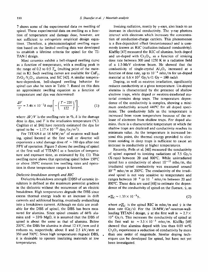
7 shows some of the experimental data on swelling of spinel. These experimental data on swelling as a func- tion of temperature and damage dose, however, are not sufficient to extrapolate empirical design equa- tions. Therefore, a phenomenological swelling equa- tion based on the limited swelling data was developed to establish a lifetime criteria for spinel for the TI- TAN-I design.
Most ceramics exhibit a bell-shaped swelling curve as a function of temperature, with a swelling peak in the range of 0.2 to 0.5 T m (melting point of the mate- rial in K). Such swelling curves are available for CaF 2, ZrO2-Y20 3, alumina, and SiC [42]. A similar tempera- ture-dependent, bell-shaped swelling behavior for spinel can also be seen in Table 7. Based on this data an approximate swelling equation as a function of temperature and dpa was determined:
1 --V-- =3.46 × 10⁻²⁶ exp ~, 122 ] j , (1)
where A V / V is the swelling rate in %, 6 is the damage dose in dpa, and T is the irradiation temperature (°C). Coghlan et al. [46] have recently estimated the dpa for spinel to be ~ 1.17 × 10 -z5 dpa/ (n /m2) .
For TITAN-I at 18 M W / m 2 of neutron wall load- ing, spinel located at the first wall or divertor will experience a total damage dose of ~ 180 dpa after one FPY of operation. Figure 5 shows the swelling of spinel at the first wall of TITAN-I as a function of tempera- ture and exposure time, as estimated by Eq. (1). This swelling curve shows that operating spinel below 150°C or above 350°C ensures low swelling rates and opera- tion in these temperature ranges is favored.
Dielectric-breakdown strength and RIC Dielectric-breakdown strength (DBS) of ceramic in-
sulators is defined as the maximum potential gradient in the dielectric without the occurrence of an electric breakdown. High temperatures degrade the DBS since excess thermal energy leads to an increase in drift currents and additional heating, eventually avalanching into a breakdown current. Although no data are avail- able for the DBS of spinel, the DBS has been mea- sured for alumina. Since spinel consists of 66% alu- mina and ~ 33% MgO, it is assumed that the DBS of spinel is about the same as that of alumina. Below 200°C, the DBS for alumina is about 12 kV/mm and it reduces to, respectively, about 8 and 2.5 kV/mm at 350 and 700°C. Since high temperatures degrade DBS, it is desirable to operate insulating materials at low temperatures.
Ionizing radiation, mostly by y-rays, also leads to an increase in electrical conductivity. The y-ray photons interact with electrons which increases the concentra- tion of conduction-charge carriers. This phenomenon is a flux-dependent effect (instantaneous) and is com- monly known as RIC (radiation-induced conductivity). Klaffky [47] measured the RIC of alumina, both doped and un-doped with Cr203, as a function of ionizing dose rate between 300 and 1250 K in a radiation field of a 1.5-MeV electron beam. He showed that the conductivity of single-crystal Al20 3 increased as a function of dose rate, up to 10 -4 mho /m for un-doped material at 6.6 × 10 z Gy/s (1 Gy = 100 rads).
Doping, as well as neutron irradiation, significantly reduces conductivity at a given temperature. Un-doped alumina is characterized by the presence of shallow electron traps, while doped or neutron-irradiated ma- terial contains deep traps. The temperature depen- dence of the conductivity is complex, showing a mini- mum conductivity around 440°C for all doped speci- mens. The conductivity falls as the temperature is increased from room temperature because of the re- lease of electrons from shallow traps. For doped alu- mina, there is a characteristic temperature at which the shallow traps are depleted and conductivity reaches its minimum value. As the temperature is increased be- yond this point, the thermal energy provided to elec- trons residing in deep traps is sufficient to cause an increase in conductivity at higher temperatures.
Recently, Pells et al. [48] measured the conductivity of spinel exposed to ionizing radiations of 7.5 Gy/s (X-rays) between 20 and 800°C. While unirradiated spinel has a conductivity of about 10-13 mho/m, the irradiated spinel conductivity was measured around 10 -s mho /m at 200°C. The conductivity of the irradi- ated spinel is not very sensitive to temperature and ranges between 10 -s to 10 -7 mho /m between 20 and 800°C. These data are used [48] to estimate the depen- dence of the conductivity of spinel on the fluence, 5', as
o'~ c ~ 1.33 × 10⁻⁹'y, (2)
where tr~,~c is the spinel RIC in mho / m and "~ is the dose rate (Gy/s). For the 18-MW/mZ-neutron-wall - loading TITAN-I design, 5, at the first wall is ~ 2.7 × 10⁴ Gy/s. This increases the conductivity of spinel at the first wall to ~ 3.5 × 10 -5 mho/m. Klaffky [49] showed that alumina doped with less than 0.03 wt% Cr20 3 experiences a reduction of conductivity by more than one order of magnitude. Similar doping tech- niques can be developed for spinel, but have not yet been investigated.

S. Sharafat et al. / Materials analysis 111
Radiation-produced defects also contribute to RIC. These defects increase the number of electron-scatter- ing sites and the number of deep electron traps, result- ing in an enhancement of overall conductivity. This effect is time dependent and, thus, a function of flu- ence. A single-crystal alumina irradiated to 3 × 10 24
n / m E at 150°C was shown to have an RIC even lower than that of the Cr2Oa-doped alumina by Klaffky [47]. Neutron-irradiated samples showed the lowest radia- tion-induced conductivity.
Based on the above observations, spinel has been chosen as the primary electrical-insulator material for the TITAN-I design. Most ceramic insulating materials studied in the past are "off-the-shelf ' insulators used commonly in nonirradiation environments. Although spinel appears to possess adequate properties for se- vere radiation environments, nonconventional insulat- ing materials with superior characteristics are being developed [39], [50].
5. Summary and conclusions
Among the three candidate vanadium-base alloys, V - 3 T i - I S i was chosen as the primary structural mate- rial for TITAN-I. The choice was primarily based on the irradiation behavior of this alloy. The V - 3 T i - I S i alloy outperforms V-15Cr-5Ti and VANSTAR as far as helium embrittlement, irradiation hardening, and swelling are concerned after exposure to a damage dose of 40 dpa by fast neutrons. However, V - 3 T i - I S i has the lowest thermalcreep resistance when compared to the other two alloys. The minimum-commitment method was used to extrapolate the creep-rupture data and establish the creep behavior during normal and off-normal operating conditions. From the limited creep data, it appears that V - 3 T i - I S i will be able to operate satisfactorily at elevated temperatures (700°C). To include the effects of the irradiation hardening, helium embrittlement data was used to estimate the maximum allowable design stress based on a 2 /3 creep-rupture-stress criteria. Additional creep-rupture experiments are needed to develop more precise creep-rupture models for V-3T i - IS i .
Compatibility of the vanadium-base alloys with lithium coolant was investigated. Recent test results were used to establish the anticipated degree of lithium attack on the V - 3 T i - I S i alloy. Various lithium-attack processes were examined, and particular attention was given to the interaction between vanadium and non- metallic impurities such as oxygen, nitrogen, carbon, and hydrogen. The limited available data do indicate
the possibility of a self-limiting corrosion rate on V - 3Ti - lS i because of the formation of complex vana- dium-titanium-nitride surface layers. The effects of a bimetallic-loop containing liquid lithium was also in- vestigated. Low-carbon, titanium-stabilized ferritic steel exhibits good resistance against lithium corrosion. The effects of high-velocity lithium on erosion was esti- mated using water-steel data. From a very limited set of data on erosion of refractory metals by a high-veloc- ity liquid lithium and from the water-steel experience, it seems that lithium velocity of 20 to 25 m / s should not introduce unacceptable erosion rates.
Spinel (MgAI20 4) has been chosen as the primary electrical-insulating material for the TITAN-I design based on its excellent resistance to radiation-induced swelling and retention (or increase) of strength. A phenomenological swelling equation was developed as a function of temperature and damage dose. The swelling data were incorporated into a phenomenologi- cal swelling equation which shows that spinel located close to the first wall should not experience more than a maximum of about 5% swelling if operated below 150°C or above 300°C. High operating temperatures may ensure a low swelling rate but could bring about dielectric breakdown of the insulator. Therefore, low- temperature operation ( < 150°C) is suggested. Radia- tion-induced conductivity (RIC) is a complex function of temperature, ionizing radiation dose, and neutron damage. Experiments performed on samples of single- crystal alumina and polycrystalline spinel indicate ade- quate resistance to RIC in a fusion environment. Radi- ation-induced conductivity of doped alumina has been investigated and it has been shown that doping can drastically reduce RIC. It is anticipated that doped spinel will show similar positive effects. Development of new ceramic insulating materials capable of with- standing intense radiation environments is in the early stages.
Acknowledgements
The TITAN research program is supported by the U.S. Department of Energy, Office of Fusion Energy, at University of California, Los Angeles under grant DE-FG03-86ER52126, at General Atomics under con- tract DE-AC03-84ER53158, at Rensselaer Polytechnic Institute under grant DE-FG02-85ER52118, and at Los Alamos National Laboratory which is operated by the University of California for the U.S. DOE under contract W-7405-ENG-36.

112 S. Sharafat et at / Materials analysis
References
[1] F. Najmabadi, R.W. Conn, R. Krakowski, D. Steiner, K. Schultz et al., Overview of the TITAN reversed-field- pinch fusion reactor study, Fusion Engrg. Des. 23 (1993) 69-80, in this issue.
[2] D.L. Smith, B.A. Loomis, and D.R. Diercks, Vanadium- base alloys for fusion reactor applications - a review, J. Nucl. Mater. 135 (1985).
[3] D.L. Smith, G.D. Morgan, M.A. Abdou, C.C. Baker, J.D. Gordon et al., Blanket comparison and selection study - Final Report, Argonne National Laboratory report ANL/FPP-84-1 (1984).
[4] D.N. Braski, The effect of neutron irradiation on the tensile properties and microstructure of several vana- dium alloys, in: Proc. ASTM Conf. on Fusion Reactor Materials, Seattle, WA (1986).
[5] B.A. Loomis and O. Carlson, Proc. 3rd Annual Conf. on Reactive Metals, Buffalo, NY (1985) 227.
[6] D.K. Sze, P. Gierszewski, and T. Bartlitt, TITAN Tritium Issues, Fusion Engrg. Des. (to be published).
[7] I. LeMay, Principles of Mechanical Metallurgy (Elsevier, New York, 1982) p. 367.
[8] S.S. Manson and C.R. Ensign, NASA report TM.X-52999 (1971).
[9] N.M. Ghoniem and R.W. Conn, Assessment of ferritic steels for steady state fusion reactors, Fusion Reactor Design and Technology It, International Atomic Energy Agency, IAEA-TC-392-62 (1983) p. 389.
[10] D.L. Harrod and R.E. Gold, Mechanical properties of vanadium and vanadium-base alloys, Int. Met. Rev. 4 (1980) 163.
[11] R.E. Gold and R. Bajaj, Mechanical properties of candi- date vanadium alloys for fusion applications, J. Nucl. Mater. 122-123 (1984) 759.
[12] ASME Boiler and Pressure Vessel Code, 1977 Code Cases-Nuclear Components, 1977 edition, Case N-47 (1977) 1592-10.
[13] D.N. Braski, The effects of helium on the tensile proper- ties of several vanadium Alloys, in: Alloy Development for Irradiation Performance, U.S. Department of Energy report DOE/ER-0045/13 (1984).
[14] Materials Handbook for Fusion Energy Systems, Depart- ment of Energy report DOE/TIC-10122 (1980).
[15] M.S. Freed and K.J. Kelly, Nuclear Propulsion Program Quarterly Report, Pratt and Whitney Aircraft Division of United Aircraft Corp. report PWAC-355 (1961).
[16] J.R. DiStefano, Oak Ridge National Laboratory report ORNL-3551 (1964).
[17] D.L. Smith, R.H. Lee, and R.M. Yonco, Proc. 2nd Int. Conf on Liquid Metal Technology in Energy Production, Richland, WA CONF-800401-P2 (1980) 2-72.
[18] R.L. Ammon, Vanadium and vanadium-alloy compatibil- ity behaviour with lithium and sodium at elevated tem- peratures, Int. Metals Rev. 4 (1980) 255.
[19] R.L. Klueh, The effect of oxygen on the corrosion of
[36]
niobium and tantalum by liquid lithium, Oak Ridge Na- tional Laboratory report ORNL-TM-4069 (1973).
[20] R.L. Klueh, Corrosion by Liquid Metals, J.E. Draley and J.R. Weeks (Eds.), (Plenum Press, New York, 1970) pp. 177-196.
[21] R.W. Harrison, Corrosion by Liquid Metals, J.E. Draley and J.R. Weeks (Eds.) (Plenum Press, New York, 1970) pp. 217-250.
[22] C.W. Hickum, Jr., Corrosion products of the tantalum-in- terstitial oxygen-potassium system at 1800°F (9820C), J. Less Common Met. 14 (1968) 315.
[23] M.G. Kamdar, Fracture 1 (1977) 387. [24] F.L. LaQue and H.R. Copson (Eds.), Corrosion Resis-
tance of Metals and Alloys, 2nd edition (Reinhold Pub- lishing Corporation, New York, 1963).
[25] W.D. Manly, Fundamentals of Liquid Metal Corrosion, Corrosion 12 (1956) 336.
[26] C.H. Adelhelm, H.U. Borgstedt, and J. Konys, Corrosion of V-3Ti- ISi in flowing lithium, Fusion Technol. 8 (1985) 541.
[27] O.K. Chopra and D.L. Smith, Corrosion behavior of vanadium alloys in flowing lithium, in: Proc. 3rd Int. Conf. on Fusion Reactor Materials, Karlsruhe, Federal Republic of Germany (1987).
[28] B. Craig, Hydrogen damage, Metals Handbook, 9th edi- tion 13 (1987) 171.
[29] A. Coulon et al., Erosion and erosion corrosion of met- als, Proc. 5th Int. Conf. on Erosion by Solid and Liquid Impact, Newnham College Cambridge, U.K. (1979) 25-1.
[30] J.E. Field et al., Liquid jet impact and damage assess- ment for brittle solids, Proc. 5th Int. Conf. on Erosion by Solid and Liquid Impact, Newnham College Cambridge, UK (1979) 13-1.
[31] G. Dearnaley, Ion implantation and ion beam mixing in corrosion science and technology, Proc. of an Int. Sym. Cosponsored by the Corrosion Division of the Electro- chemical Soc. and the European Federation of Corro- sion, Pennington, NJ (1983) 1-16.
[32] G.W. Vickers, Characterization and determination of erosion damage resulting from liquid jet impact, Ph. D. Thesis, University of Manchester, Institute of Science and Technology, UK (1972).
[33] J.E. Field, S. van der Zwaag, and D. Townsend, Liquid impact damage assessment for a range of infra-red mate- rials, Proc. of 6th Int. Conf. on Erosion by Liquid and Solid Impact, Newnham College, UK (1983) 21-1.
[34] B.J. Hockey, Erosion of ceramic materials: the role of plastic flow, Proc. 5th Int. Conf. on Erosion by Solid and Liquid Impact, Newnham College Cambridge, UK (1979) 26-1.
[35] L.G. Hays, Corrosion of n iobium-l% zirconium alloy and yttria by lithium at high flow velocities, NASA-JPL Technical report 32-1233 (1967). K. Tanimura, N. Itoh, and F.W. Clinard, Jr., Volume change in Al20 3 and MgA]204 induced by 14-MeV neutron irradiation, J. Nucl. Mater. 150 (1987) 182.

S. Sharafat et aL / Materials analysis 113
[37] G.F. Hurley and F.W. Clinard, Jr., Fracture toughness and hardness of neutron-irradiated AI20 3, MgAI204, and Y3AIsOiz, Special Purpose Materials, Annual Progress Report Ending October 1979, U.S. Department of Energy report DOE/ER-0048/1 (1980)51.
[38] F.W. Clinard, Jr., G.F. Hurley, L.W. Hobbs, D.L. Rohr, and R.A. Youngman, Structural performance of ceramics in a high-fluence fusion environment, J. Nucl. Mater. 122-123 (1984) 1386.
[39] C.A. Parker, L.W. Hobbs, K.C. Russel, and F.W. Cli- nard, Jr., Damage structures in fast neutron irradiated magnesium aluminate and electron irradiated aluminum oxynitride spinels, J. Nucl. Mater. 133-134 (1985) 741.
[40] G.R. Hopkins and R.J. Price, Fusion reactor design with ceramics, Nucl. Engrg. Des./Fusion 2 (1985) 111.
[41] F.W. Clinard, Jr., L.W. Hobbs, and R.A. Youngman, Microstructure of neutron-irradiated MgAI204, Special Purpose Materials, Annual Progress Report Ending Oc- tober 1979, U.S. Depar tment of Energy report DOE/ER-0048/1 (1980) 59.
[42] G.F. Hurley, J.C. Kennedy, F.W. Clinard, Jr., R.A. Youngman, and W.R. McDonell, Structural properties of MgO and MgAl204 after fission neutron irradiation near room temperature, J. Nucl. Mater. 103-104 (1981) 761.
[43] F.W. Clinard, Jr., Ceramics for application in fusion systems, J. Nucl. Mater. 85-86 (1976) 393.
[44] F.W. Clinard, Jr. and G.F. Hurley, Ceramic and organic insulators for fusion applications, J. Nucl. Mater. 103-104 (1981) 705.
[45] F.W. Clinard, Jr., G.F. Hurley, and L.W. Hobbs, Neutron irradiation damage in MgO, Al20 3 and MgAI20 ceram- ics, J. Nucl. Mater. 108-109 (1982) 655.
[46] W.A. Coghlan, F.W. Clinard, Jr., N. Itoh, and L.R. Greenwood, Swelling of spinel after low-dose neutron irradiation, in: Proc. 2nd Int. Conf. on Fusion Reactor Materials, Chicago, IL (1986).
[47] W. Klaffky, Radiation-induced conductivity of Al20 3, Special Purpose Materials, Annual Progress Report End- ing October 1979, U.S. Department of Energy report DOE/ER-0048/1 (1980) 19.
[48] G.P. Pells, S.N. Buckley, G.J. Hill, and M.J. Murphy, Radiation effects in electrically insulating ceramics, Har- well Laboratory report AERE-R 11715 (1985).
[49] R.W. Klaffky, RIC of Al20 3 experiment and theory, Phys. Rev. B 21 (1980) 3610.
[50] J.W. McCauley and N.D. Corbin, Progress in Nitrogen Ceramics, F.L. Riley (Ed.), (Martinus Nijhof, Boston, 1983) 111.