material used: tin lead zinc silver antimony copper aluminum
TRANSCRIPT

DISTRIBUTION FEEDER PROTECTION

FUSE PROTECTIONMaterial used:
TinLeadZincSilverAntimonyCopperAluminum

Fuse Law
Heat generated = I2.R = I2.( ℓ. )
Again heat lost ∞ Surface area of the fuse wire
= K1.∏.d.lHence,
K1.∏.d.l = I2.( ℓ. ) or, I ∞ d 3/2
Where, I = current through the fuse wireℓ= resistivity of the fuse materiald = diameter of the fuse wireL = length of the fuse wireK1= parameter constant
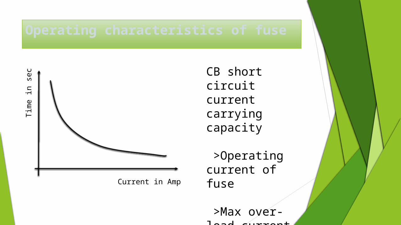
Operating characteristics of fuse
CB short circuit current carrying capacity
>Operating current of fuse
>Max over-load current
Tim
e in s
ec
Current in Amp
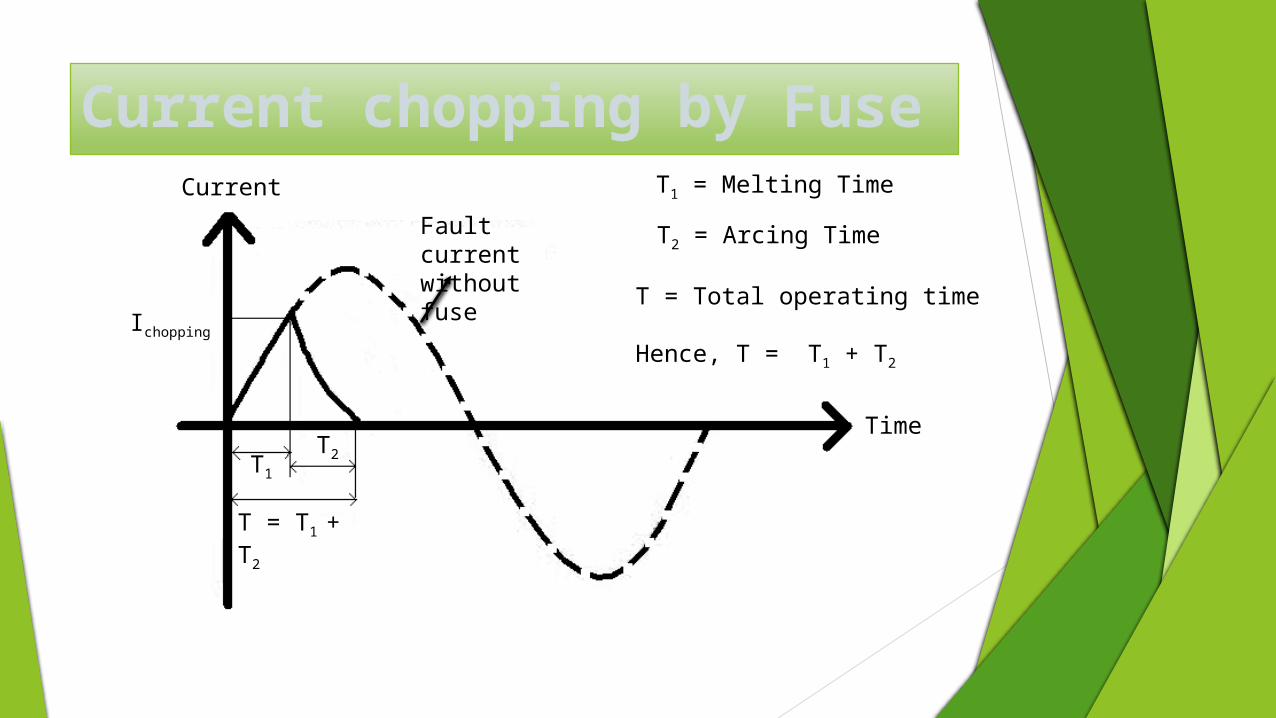
Current chopping by FuseCurrent
Time
Ichopping
T1 = Melting Time
T2 = Arcing Time
T = Total operating time
Hence, T = T1 + T2
T1
T2
T = T1 + T2
Fault current without fuse
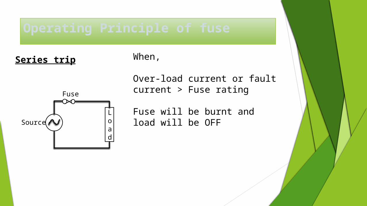
Operating Principle of fuse
Load
Fuse
Source
Series trip When,
Over-load current or fault current > Fuse rating
Fuse will be burnt and load will be OFF
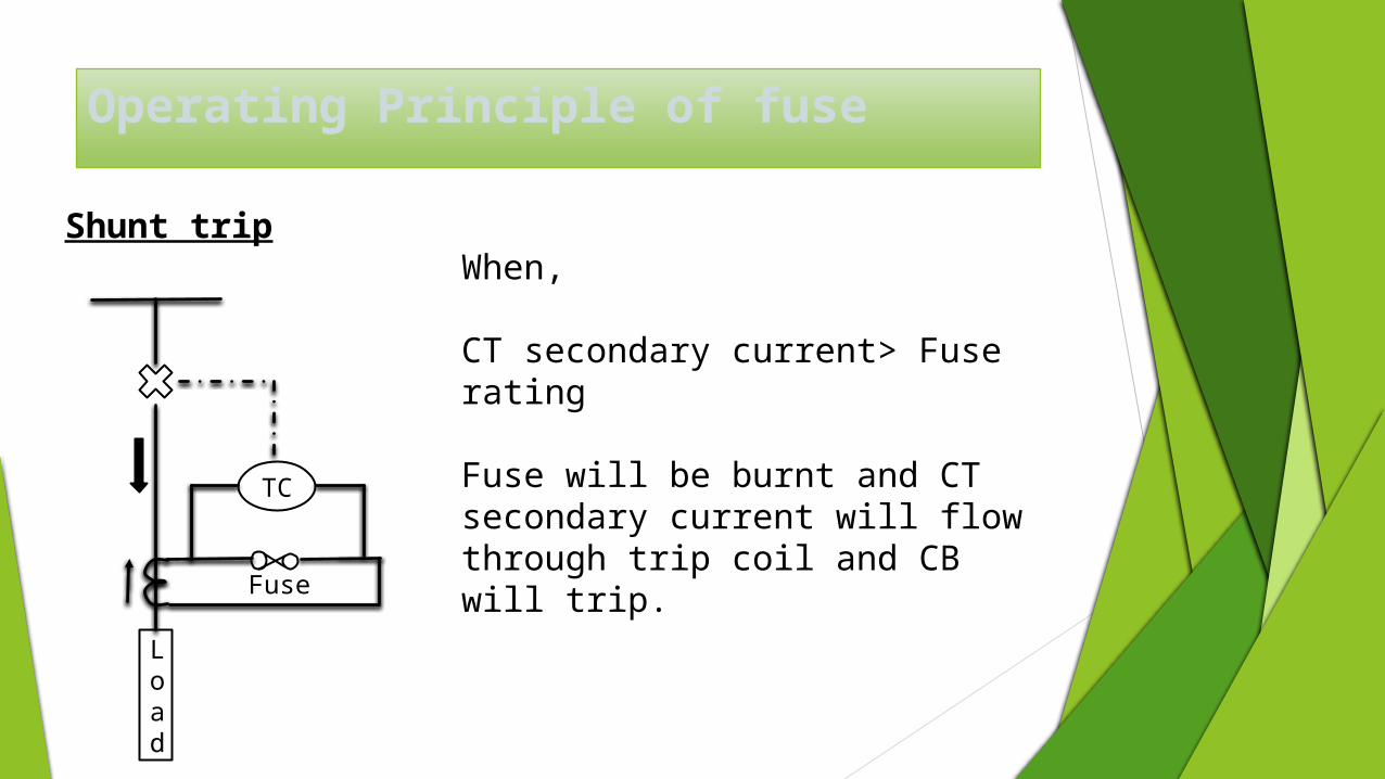
Operating Principle of fuse
Load
Fuse
Shunt tripWhen,
CT secondary current> Fuse rating
Fuse will be burnt and CT secondary current will flow through trip coil and CB will trip.
TC
CLASSIFICATION OF FUSES
Fuses are classified on the basis of
Continuous current carrying capacityOverload capacityResponse characteristicsVoltage rating
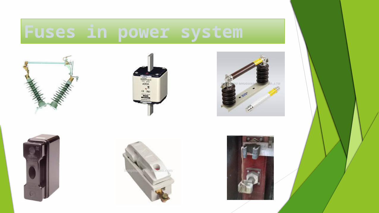
Fuses in power system

Use of fuses
Use of fuses
MotorAir-conditionerLaptopCell-phonePrinters
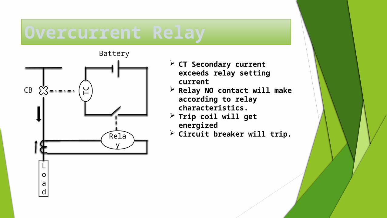
Overcurrent Relay
Load
TC
Relay
Battery
CB
CT Secondary current exceeds relay setting current
Relay NO contact will make according to relay characteristics.
Trip coil will get energized Circuit breaker will trip.
O/C relay Vs. Fuse Protection O/C relay is more accurate and versatile than Fuse
protection
O/C relay is more costly and more complicated than fuse.
Time gradation is difficult in case of fuse protection
Once fuse melts protection cannot be re-commissioned until it is replaced.
Unlike relay, fuse characteristics is temperature dependent.
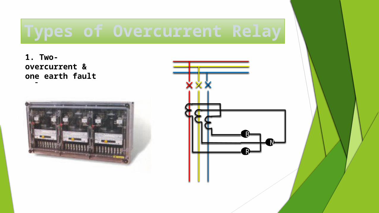
Types of Overcurrent Relay
B
RN
1. Two-overcurrent & one earth fault relay
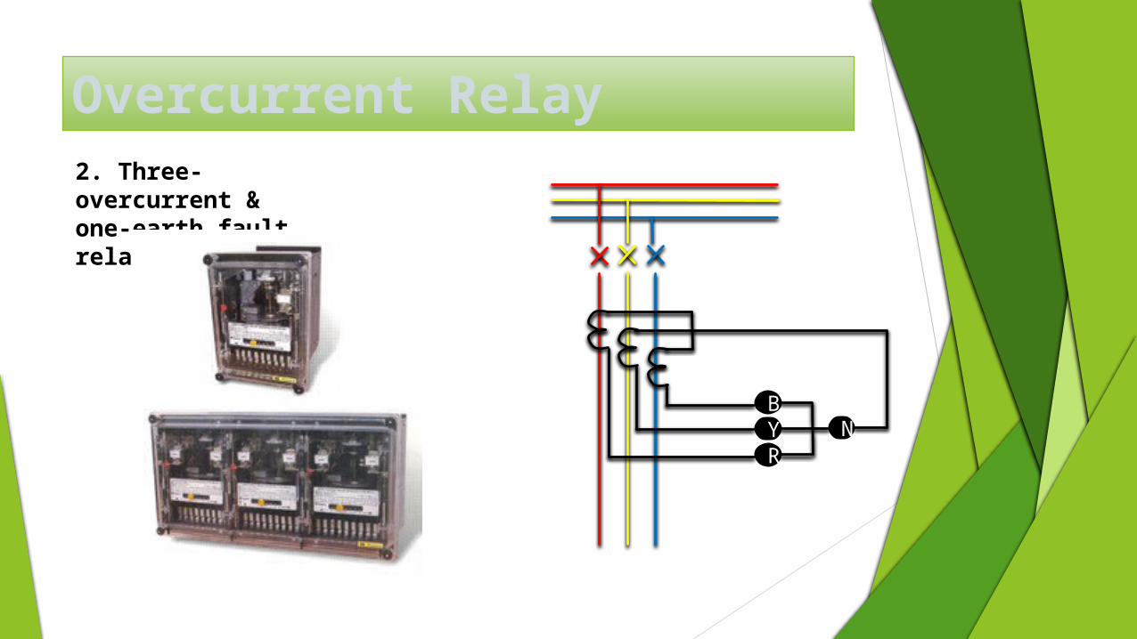
Overcurrent Relay2. Three-overcurrent & one-earth fault relay
BYR
N
Overcurrent Relay setting Overcurrent relay current setting = 125% of
nominal load current
Under 3-ph balanced load condition, Earth Fault relay will sense zero current. Thus this relay has to be very sensitive.
Earth fault current setting = 20% of rated current
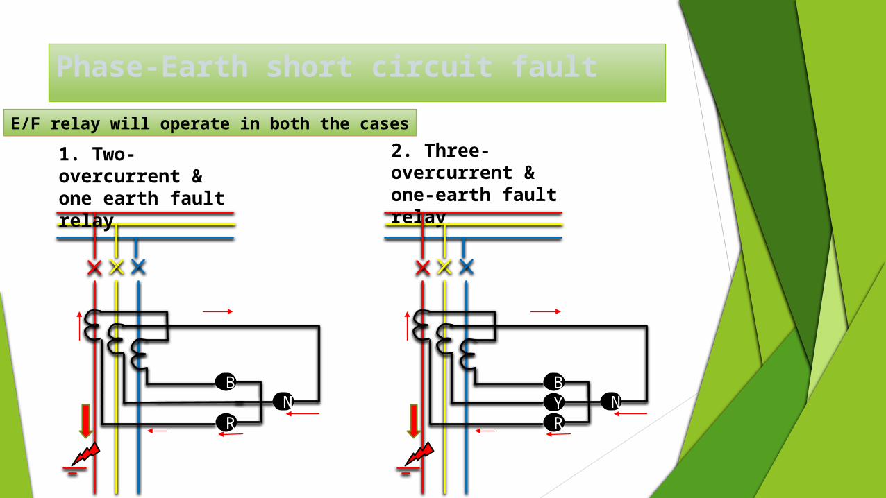
Phase-Earth short circuit fault
B
RN
1. Two-overcurrent & one earth fault relay
2. Three-overcurrent & one-earth fault relay
BYR
N
E/F relay will operate in both the cases
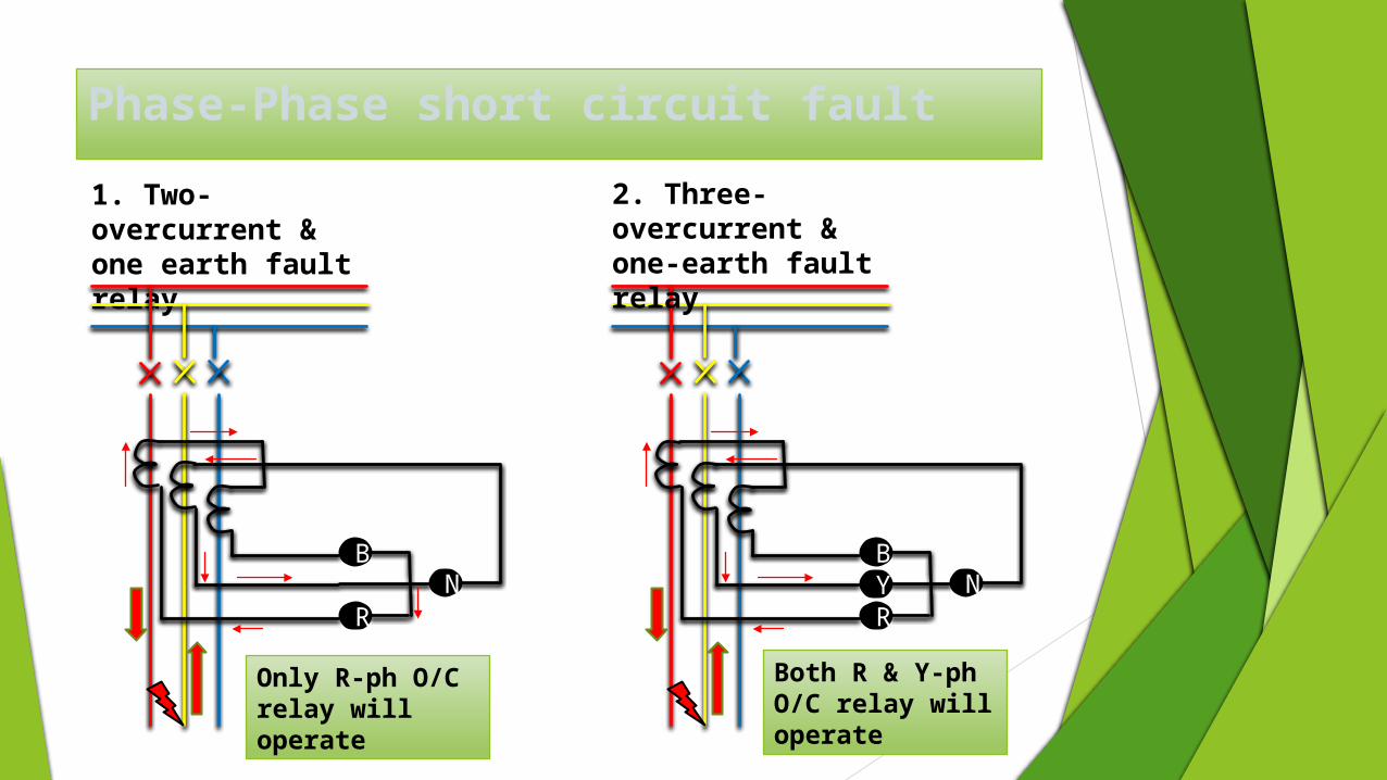
Phase-Phase short circuit fault
BYR
N
1. Two-overcurrent & one earth fault relay
2. Three-overcurrent & one-earth fault relay
B
RN
Only R-ph O/C relay will operate
Both R & Y-ph O/C relay will operate
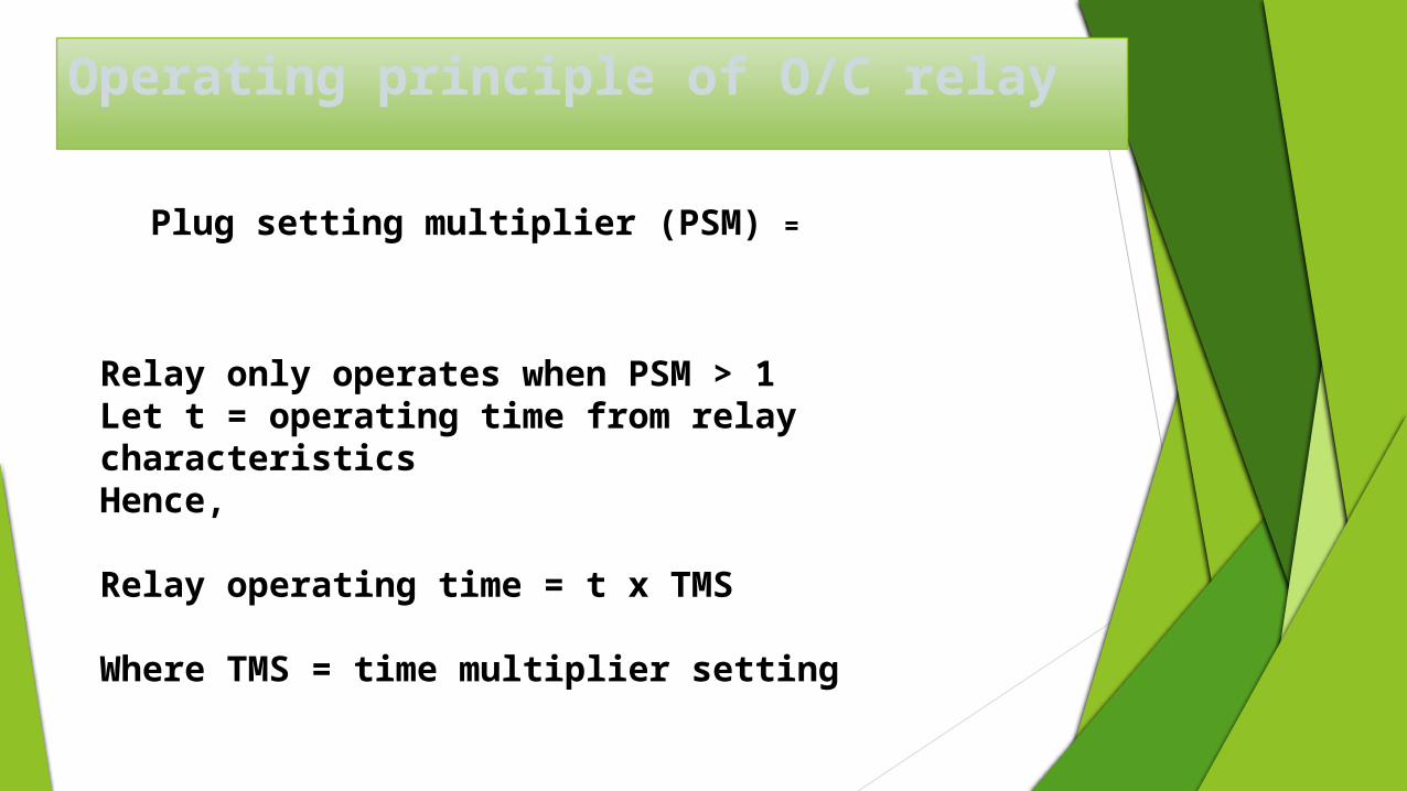
Operating principle of O/C relay
Plug setting multiplier (PSM) =
Relay only operates when PSM > 1Let t = operating time from relay characteristicsHence, Relay operating time = t x TMS
Where TMS = time multiplier setting
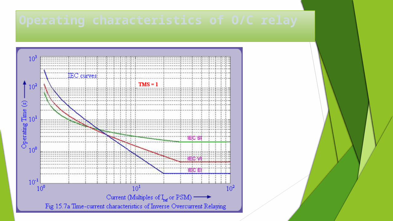
Operating characteristics of O/C relay
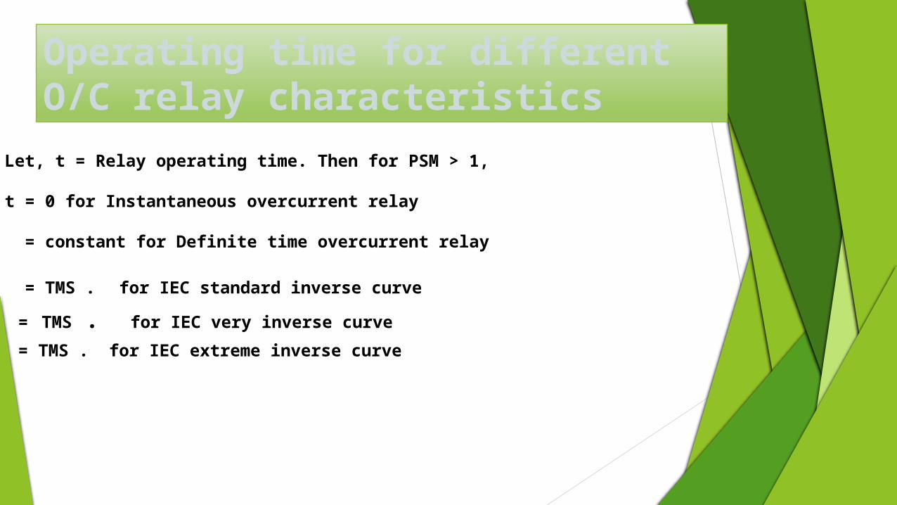
Operating time for different O/C relay characteristics
Let, t = Relay operating time. Then for PSM > 1,
t = 0 for Instantaneous overcurrent relay
= constant for Definite time overcurrent relay
= TMS . for IEC standard inverse curve
= TMS . for IEC very inverse curve
= TMS . for IEC extreme inverse curve
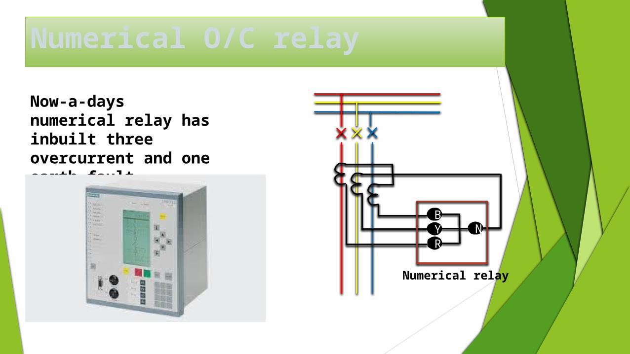
Numerical O/C relay
Now-a-days numerical relay has inbuilt three overcurrent and one earth fault element.
BYR
N
Numerical relay

Typical algorithm of Numerical O/C relay
Protection
healthy
Iinput
Calculate
Irms
Compute PSM
=Iinput/Irms
If PSM>
1
Start timer
T1
If Type
= DT
DT delay top
If Type= SI
Compute top
If Type= VI
Compute top
If Type= EI
Compute top
If Top>T1
Alarm
Trip
yes
yes yes yes
yes
yes
yes
no
no
no
no
no
no
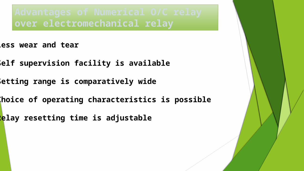
Less wear and tear
Self supervision facility is available
Setting range is comparatively wide
Choice of operating characteristics is possible
Relay resetting time is adjustable
Advantages of Numerical O/C relay over electromechanical relay
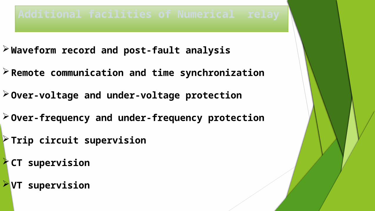
Additional facilities of Numerical relay
Waveform record and post-fault analysis
Remote communication and time synchronization
Over-voltage and under-voltage protection
Over-frequency and under-frequency protection
Trip circuit supervision
CT supervision
VT supervision
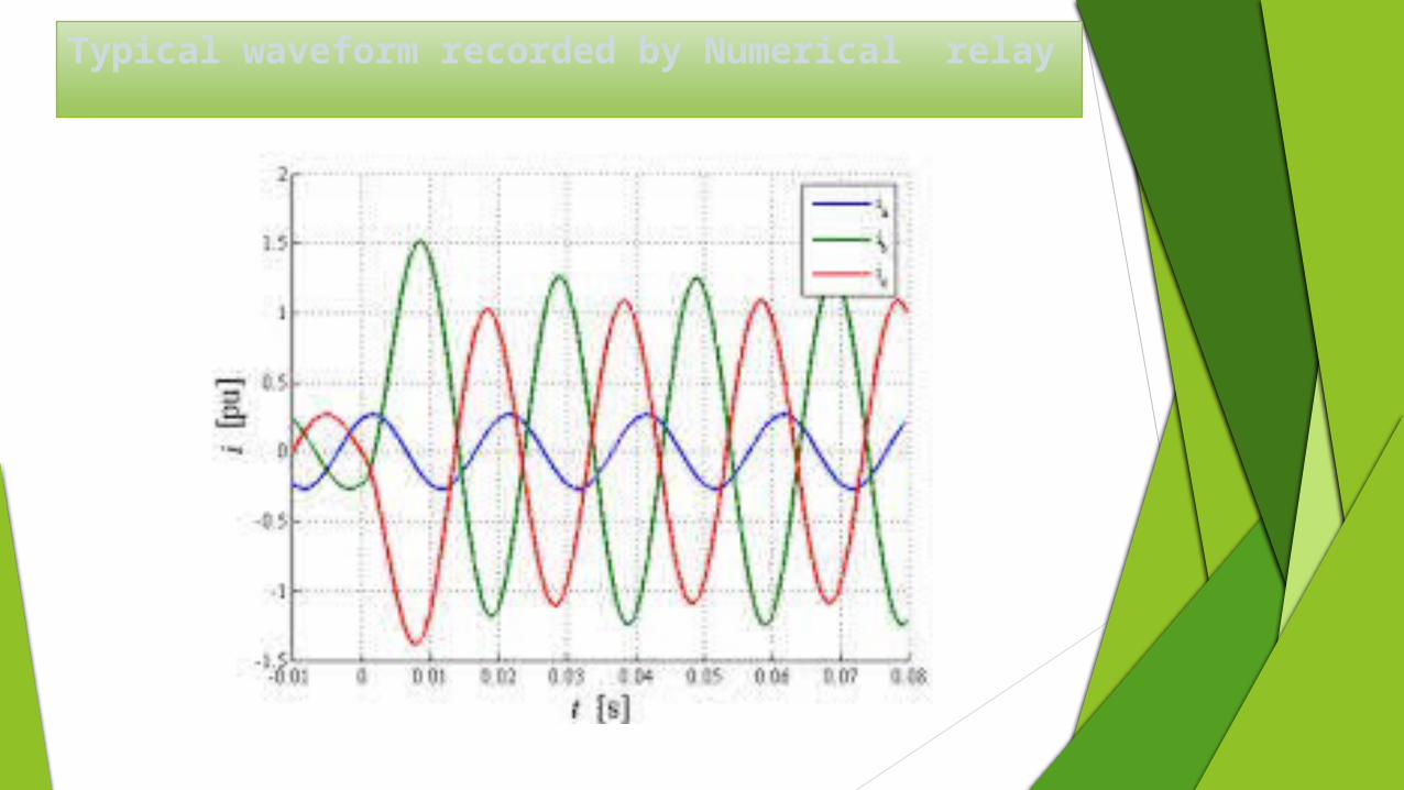
Typical waveform recorded by Numerical relay
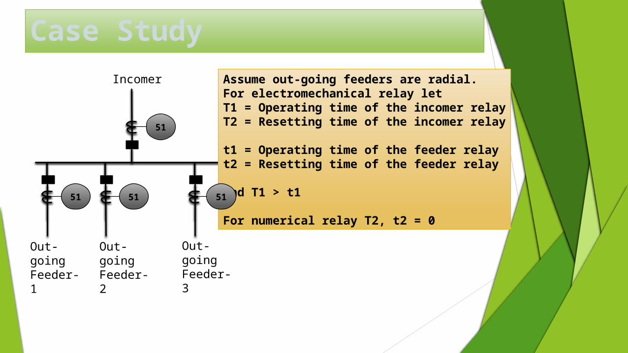
Case Study
Incomer
Out-going Feeder-1
Out-going Feeder-2
Out-going Feeder-3
Assume out-going feeders are radial.For electromechanical relay let T1 = Operating time of the incomer relayT2 = Resetting time of the incomer relay
t1 = Operating time of the feeder relayt2 = Resetting time of the feeder relay
And T1 > t1
For numerical relay T2, t2 = 0
51
51
51
51
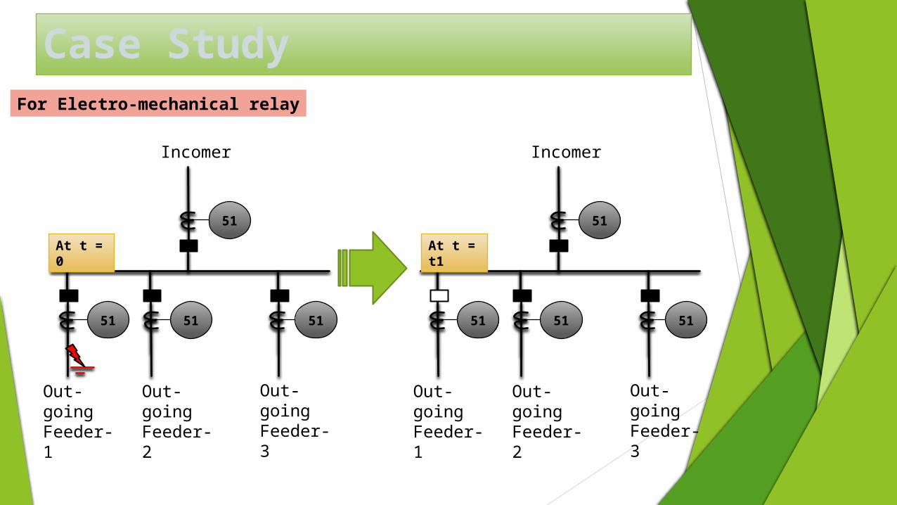
Case Study
Incomer
Out-going Feeder-1
Out-going Feeder-2
Out-going Feeder-3
At t = 0
51
51
51
51
Incomer
Out-going Feeder-1
Out-going Feeder-2
Out-going Feeder-3
51
51
51
51
At t = t1
For Electro-mechanical relay
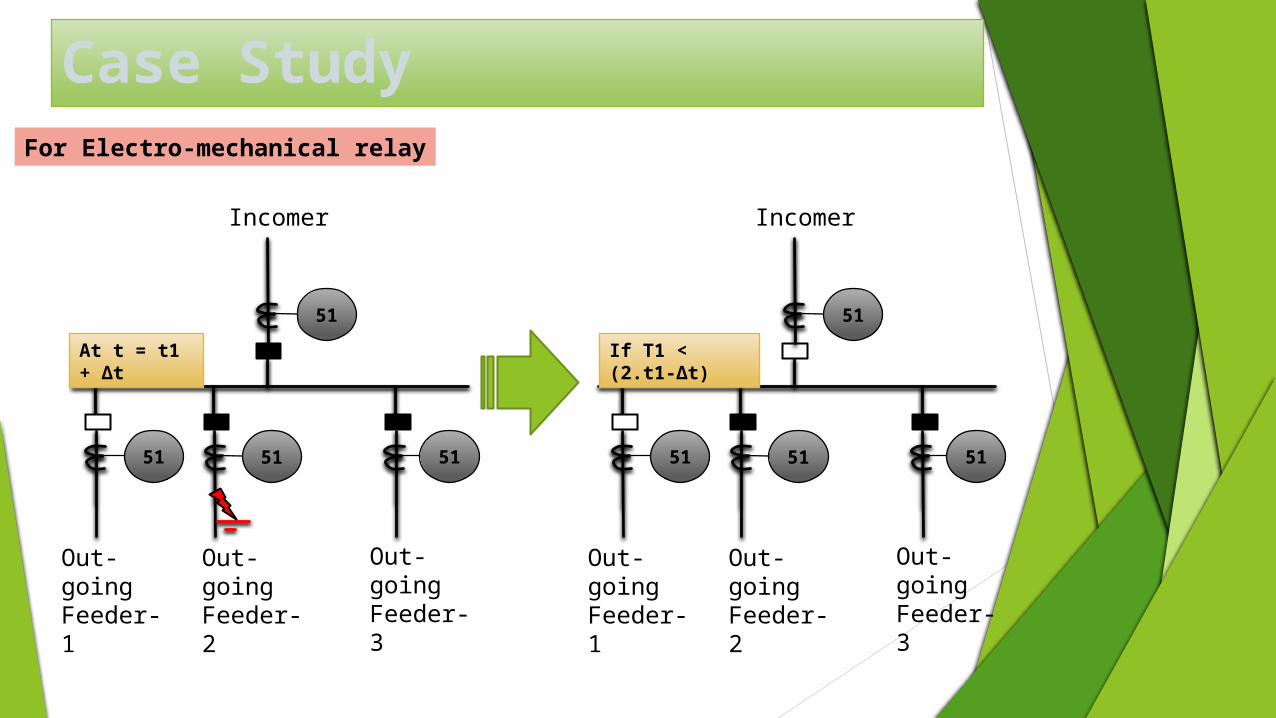
Case Study
Incomer
Out-going Feeder-1
Out-going Feeder-2
Out-going Feeder-3
At t = t1 + Δt
51
51
51
51
Incomer
Out-going Feeder-1
Out-going Feeder-2
Out-going Feeder-3
51
51
51
51
If T1 < (2.t1-Δt)
For Electro-mechanical relay
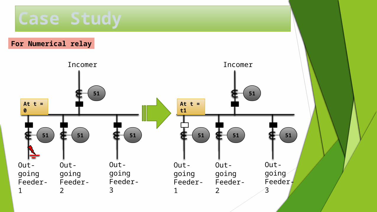
Case Study
Incomer
Out-going Feeder-1
Out-going Feeder-2
Out-going Feeder-3
At t = 0
51
51
51
51
Incomer
Out-going Feeder-1
Out-going Feeder-2
Out-going Feeder-3
51
51
51
51
At t = t1
For Numerical relay
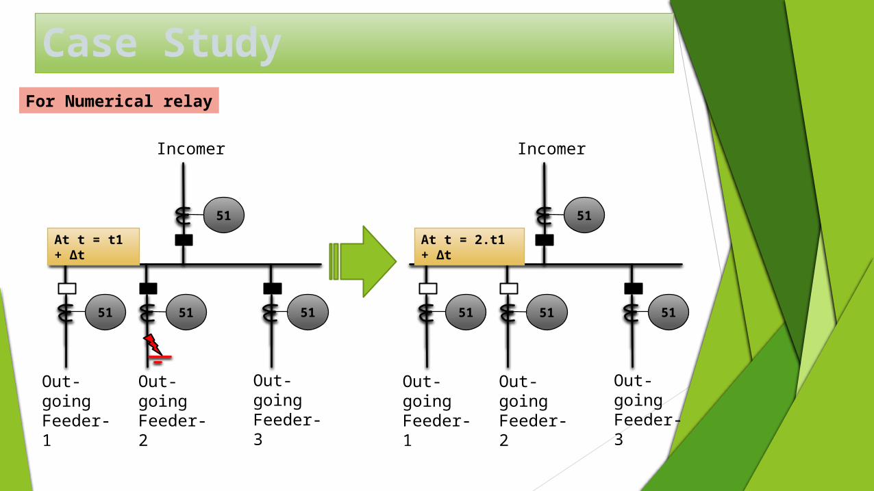
Case Study
Incomer
Out-going Feeder-1
Out-going Feeder-2
Out-going Feeder-3
At t = t1 + Δt
51
51
51
51
Incomer
Out-going Feeder-1
Out-going Feeder-2
Out-going Feeder-3
51
51
51
51
At t = 2.t1 + Δt
For Numerical relay
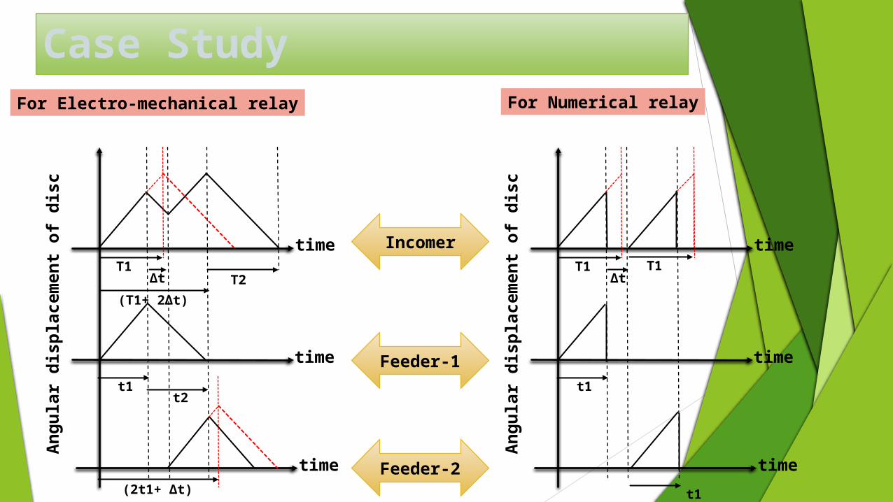
Case StudyFor Numerical relayFor Electro-mechanical relay
time
time
time
An
gu
lar
dis
pla
cem
en
t of
dis
c
T1T2
t1t2
Incomer
Feeder-1
Feeder-2
Δt
(T1+ 2Δt)
(2t1+ Δt)
time
time
time
An
gu
lar
dis
pla
cem
en
t of
dis
c
T1
t1
Δt
t1
T1
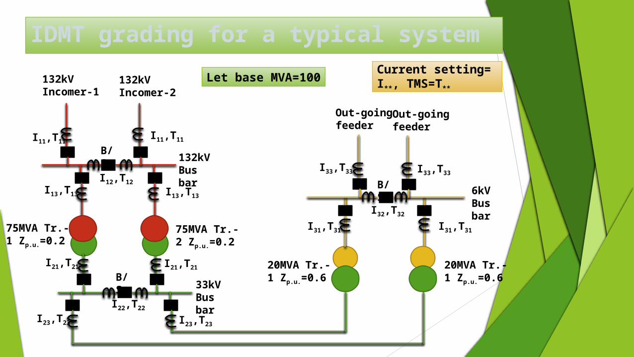
IDMT grading for a typical system
132kV Incomer-1
132kV Incomer-2
132kV Bus bar
33kV Bus bar
6kV Bus bar
75MVA Tr.-2 Zp.u.=0.2
75MVA Tr.-1 Zp.u.=0.2
20MVA Tr.-1 Zp.u.=0.6
20MVA Tr.-1 Zp.u.=0.6
Out-going feeder
Out-going feeder
B/S
B/S
B/S
I11,T11I11,T11
I12,T12
I13,T13I13,T13
I21,T21
I22,T22
I23,T23
I21,T21
I23,T23
I31,T31 I31,T31
I32,T32
I33,T33 I33,T33
Current setting= I**, TMS=T**
Let base MVA=100
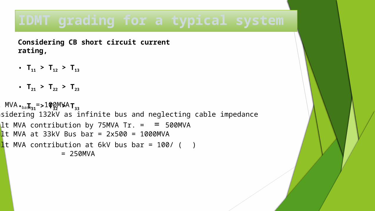
IDMT grading for a typical systemConsidering CB short circuit current rating,
• T11 > T12 > T13
• T21 > T22 > T23
• T31 > T32 > T33Let MVA base = 100MVA Considering 132kV as infinite bus and neglecting cable impedance
Fault MVA contribution by 75MVA Tr. = = 500MVAFault MVA at 33kV Bus bar = 2x500 = 1000MVA
Fault MVA contribution at 6kV bus bar = 100/ ( ) = 250MVA
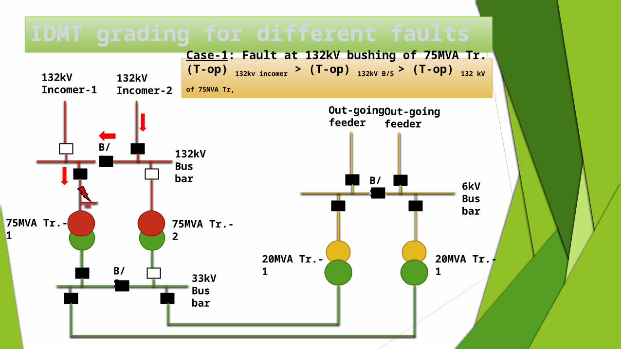
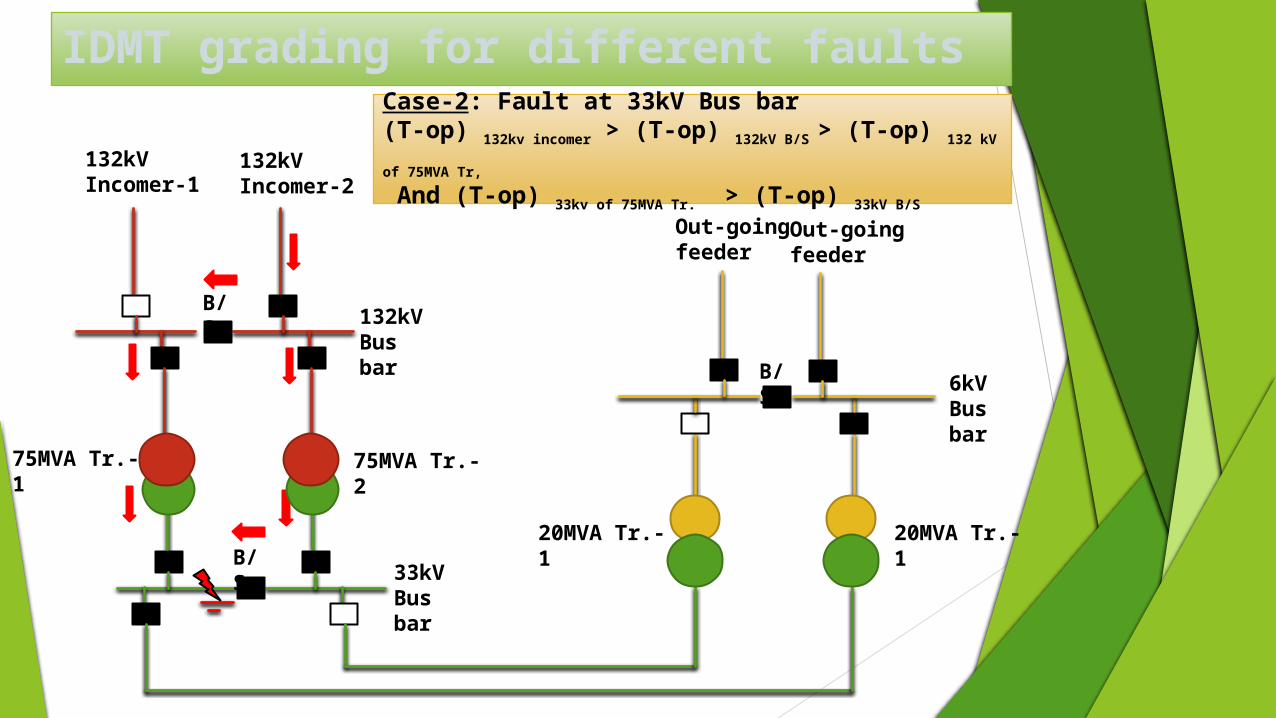
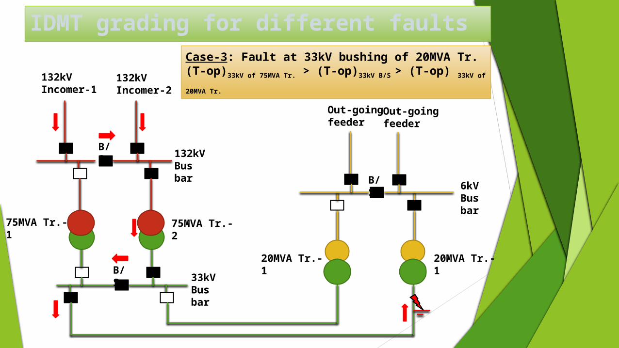
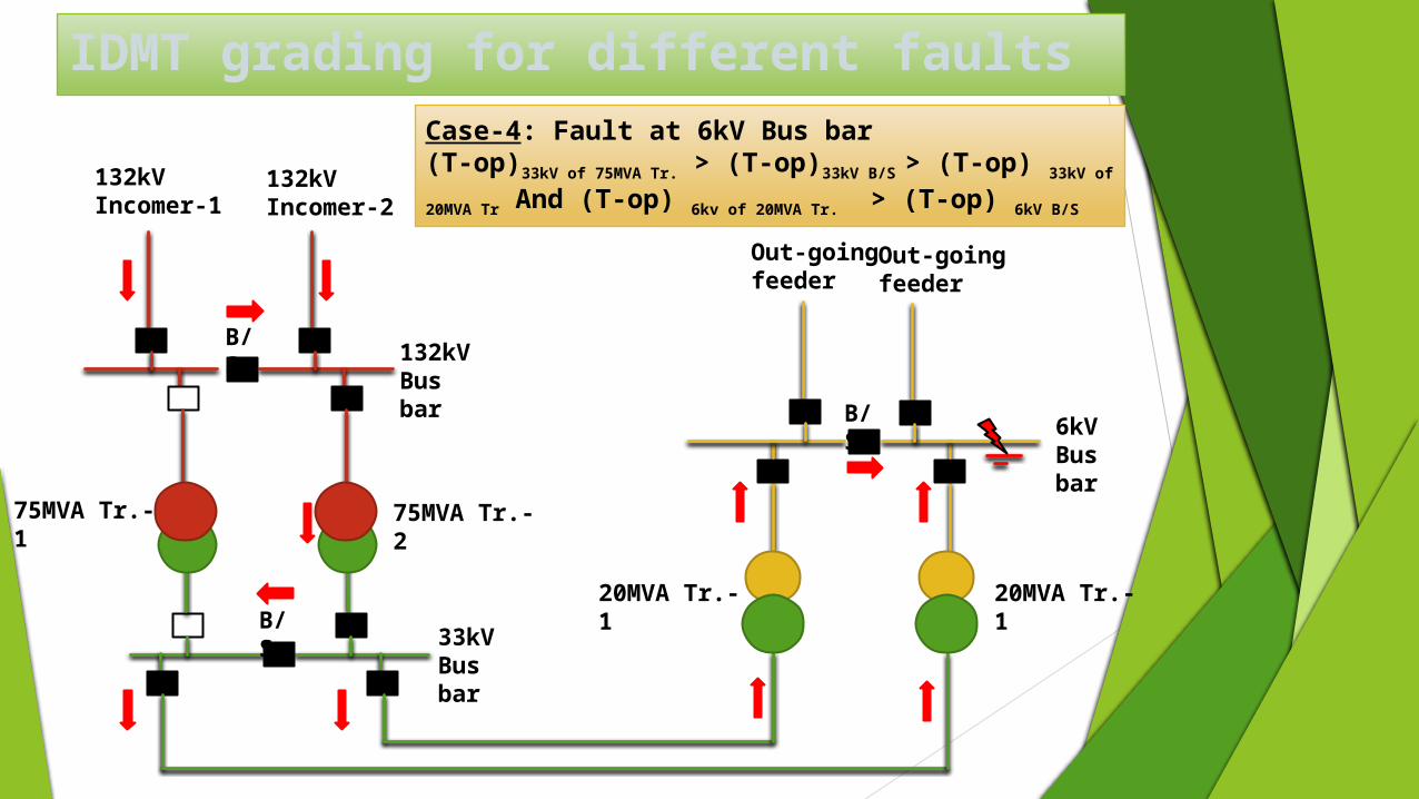
IDMT grading for different faults
132kV Incomer-1
132kV Incomer-2
132kV Bus bar
33kV Bus bar
6kV Bus bar
75MVA Tr.-2
75MVA Tr.-1
20MVA Tr.-1
20MVA Tr.-1
Out-going feeder
Out-going feeder
B/S
B/S
B/S
Case-1: Fault at 132kV bushing of 75MVA Tr.(T-op) 132kv incomer > (T-op) 132kV B/S > (T-op) 132 kV of
75MVA Tr,
IDMT grading for different faults
132kV Incomer-1
132kV Incomer-2
132kV Bus bar
33kV Bus bar
6kV Bus bar
75MVA Tr.-2
75MVA Tr.-1
20MVA Tr.-1
20MVA Tr.-1
Out-going feeder
Out-going feeder
B/S
B/S
B/S
Case-2: Fault at 33kV Bus bar(T-op) 132kv incomer > (T-op) 132kV B/S > (T-op) 132 kV of
75MVA Tr,
And (T-op) 33kv of 75MVA Tr. > (T-op) 33kV B/S
IDMT grading for different faults
132kV Incomer-1
132kV Incomer-2
132kV Bus bar
33kV Bus bar
6kV Bus bar
75MVA Tr.-2
75MVA Tr.-1
20MVA Tr.-1
20MVA Tr.-1
Out-going feeder
Out-going feeder
B/S
B/S
B/S
Case-3: Fault at 33kV bushing of 20MVA Tr.(T-op)33kV of 75MVA Tr. > (T-op)33kV B/S > (T-op) 33kV of
20MVA Tr.
IDMT grading for different faults
132kV Incomer-1
132kV Incomer-2
132kV Bus bar
33kV Bus bar
6kV Bus bar
75MVA Tr.-2
75MVA Tr.-1
20MVA Tr.-1
20MVA Tr.-1
Out-going feeder
Out-going feeder
B/S
B/S
B/S
Case-4: Fault at 6kV Bus bar(T-op)33kV of 75MVA Tr. > (T-op)33kV B/S > (T-op) 33kV of
20MVA Tr And (T-op) 6kv of 20MVA Tr. > (T-op) 6kV B/S
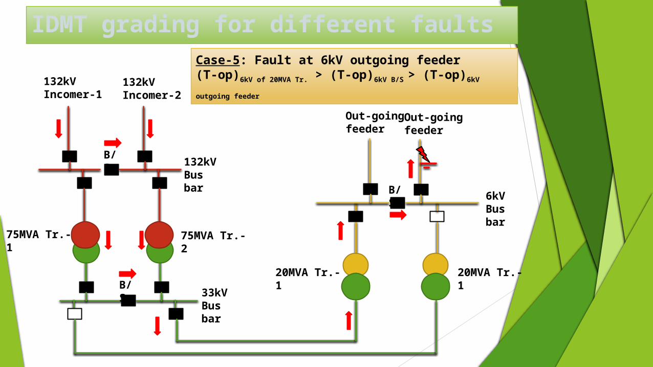
IDMT grading for different faults
132kV Incomer-1
132kV Incomer-2
132kV Bus bar
33kV Bus bar
6kV Bus bar
75MVA Tr.-2
75MVA Tr.-1
20MVA Tr.-1
20MVA Tr.-1
Out-going feeder
Out-going feeder
B/S
B/S
B/S
Case-5: Fault at 6kV outgoing feeder(T-op)6kV of 20MVA Tr. > (T-op)6kV B/S > (T-op)6kV outgoing
feeder
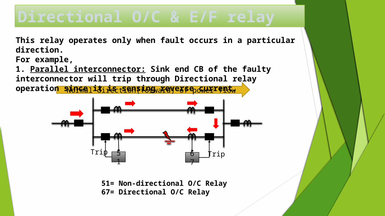
Directional O/C & E/F relay
Normal direction(forward) of power flow
51
67
51= Non-directional O/C Relay67= Directional O/C Relay
Trip Trip
This relay operates only when fault occurs in a particular direction.For example,1. Parallel interconnector: Sink end CB of the faulty interconnector will trip through Directional relay operation since it is sensing reverse current.
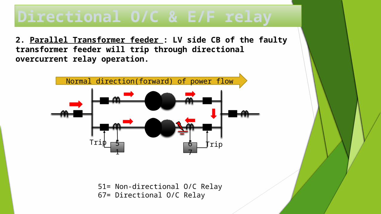
Directional O/C & E/F relay
Normal direction(forward) of power flow
51
67
51= Non-directional O/C Relay67= Directional O/C Relay
Trip Trip
2. Parallel Transformer feeder : LV side CB of the faulty transformer feeder will trip through directional overcurrent relay operation.
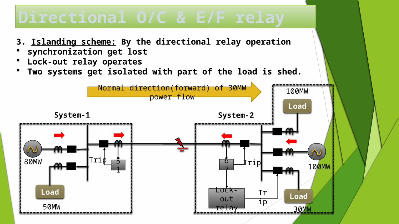
Directional O/C & E/F relay
Normal direction(forward) of 30MW power flow
Lock-out
relay
3. Islanding scheme: By the directional relay operation synchronization get lost Lock-out relay operates Two systems get isolated with part of the load is shed.
LoadLoad
Load
100MW
100MW
30MW50MW
80MW 51
Trip 67
Trip
Trip
System-1 System-2
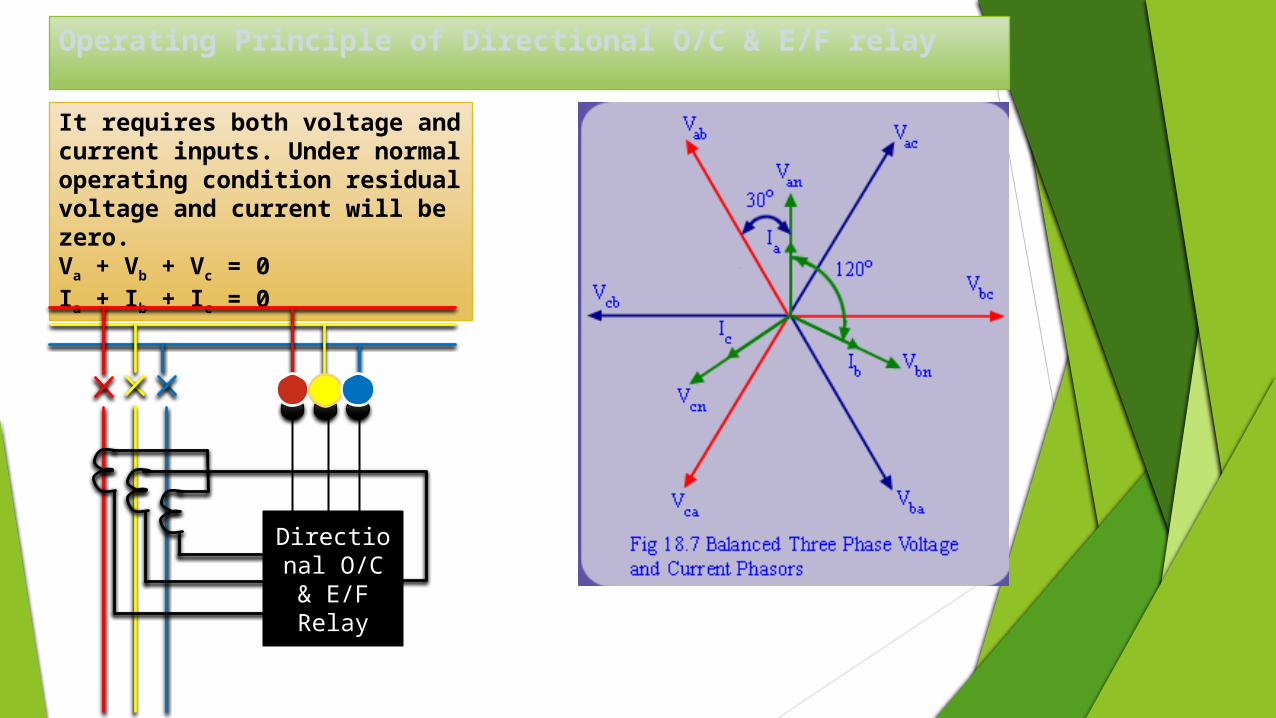
Operating Principle of Directional O/C & E/F relay
It requires both voltage and current inputs. Under normal operating condition residual voltage and current will be zero.Va + Vb + Vc = 0Ia + Ib + Ic = 0
BYR
NDirectional O/C & E/F Relay
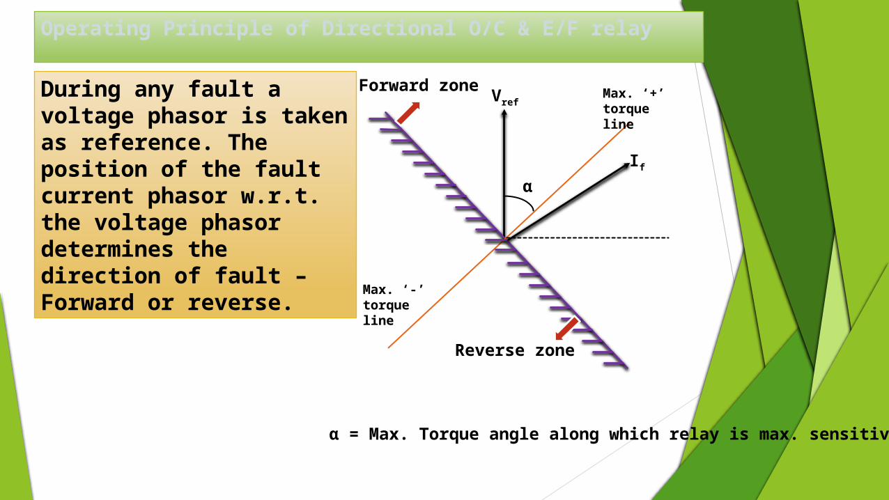
Operating Principle of Directional O/C & E/F relay
During any fault a voltage phasor is taken as reference. The position of the fault current phasor w.r.t. the voltage phasor determines the direction of fault – Forward or reverse.
Vref
α
Max. ‘+’ torque line
Max. ‘-’ torque line
Forward zone
Reverse zone
If
α = Max. Torque angle along which relay is max. sensitive
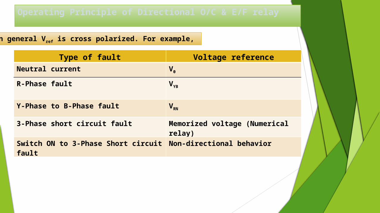
Operating Principle of Directional O/C & E/F relay
In general Vref is cross polarized. For example,
Type of fault Voltage reference
Neutral current V0
R-Phase fault VYB
Y-Phase to B-Phase fault VRN
3-Phase short circuit fault Memorized voltage (Numerical relay)
Switch ON to 3-Phase Short circuit fault
Non-directional behavior
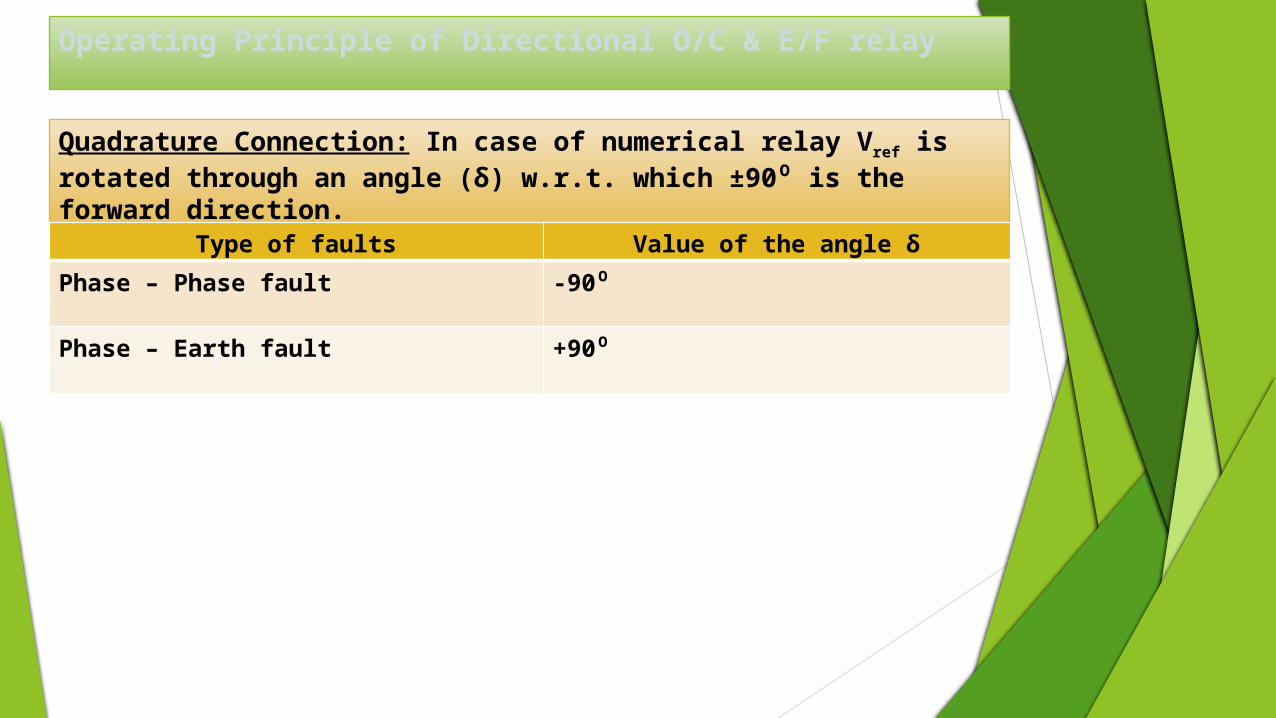
Operating Principle of Directional O/C & E/F relay
Quadrature Connection: In case of numerical relay Vref is rotated through an angle (δ) w.r.t. which ±90⁰ is the forward direction.
Type of faults Value of the angle δ
Phase – Phase fault -90⁰
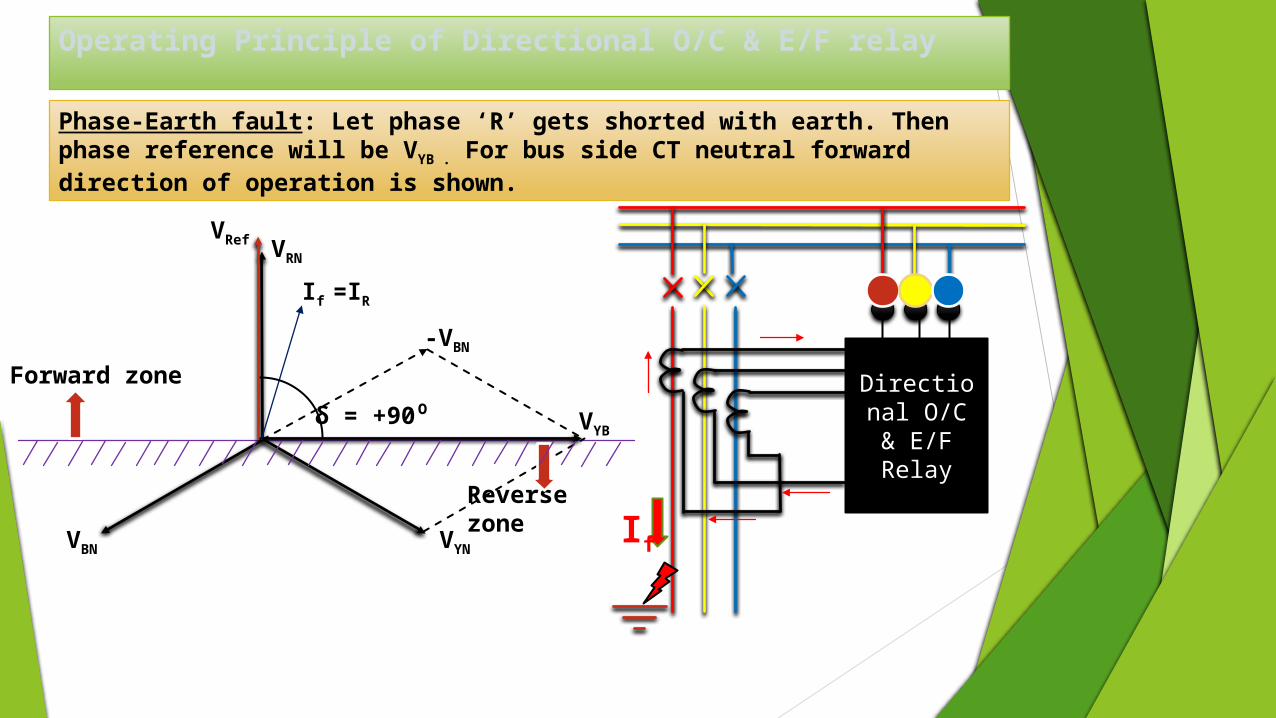
Phase – Earth fault +90⁰
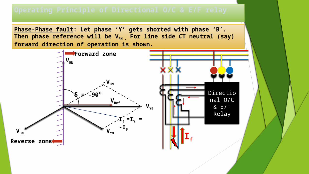
Operating Principle of Directional O/C & E/F relay
Phase-Phase fault: Let phase ‘Y’ gets shorted with phase ‘B’. Then phase reference will be VRN . For line side CT neutral (say) forward direction of operation is shown.
Directional O/C &
E/F Relay
VR
N
δ = -90⁰
Forward zone
If =IY = -IB
If
VYNVBN
-VBN
VYB
VRef
Reverse zone
Operating Principle of Directional O/C & E/F relay
Phase-Earth fault: Let phase ‘R’ gets shorted with earth. Then phase reference will be VYB . For bus side CT neutral forward direction of operation is shown.
Directional O/C &
E/F Relay
VR
N
δ = +90⁰
Forward zone
If =IR
IfVYNVBN
-VBN
VYB
VRef
Reverse zone

THANK YOU