material-saving design strategies for tall building structures
TRANSCRIPT

CTBUH 8th World Congress 2008 �
Biography Dr. Kyoung Sun Moon received his Ph.D. in Architecture: Building Technology at the Massachusetts Institute of Technol-ogy. Dr. Moon is currently Assistant Professor of Architecture at the University of Illinois at Urbana-Champaign. His teach-ing activities at Illinois include instructing tall building design studios for graduate students. Before he joined the faculty at the University of Illinois, Dr. Moon worked as an architect at Skidmore, Owings, and Merrill in Chicago, MAC Architects and Consultants in Seoul, Korea, and the Republic of Korea Navy.
Dr. Moon’s primary research area is integration between the art and science/technology of architecture, with a focus on tall buildings. His enduring interest lies in viewing architecture from a synthetic perspective that includes rigorous technology research and a deep interest in design. Dr. Moon’s publications on tall buildings include his Ph.D. dissertation entitled “Dynamic Interrelationship between Technology and Architecture in Tall Buildings” and journal papers such as “Structural Developments in Tall Buildings: Currents Trends and Future Prospects” and “Diagrid Structural Systems for Tall Build-ings: Characteristics and Methodology for Preliminary Design.”
Material-Saving Design Strategies for Tall Building Structures
Kyoung Sun Moon
Structures Division, School of Architecture, University of Illinois at Urbana-Champaign, Champaign, IL 61820, USA Tel: +1 217 333 2708, Fax: +1 217 244 2900, Email: [email protected]
Abstract Stiffness-based design methodologies for tall building structures are discussed with an emphasis on systems with diagonals such as braced tubes and more recently-developed diagrid structures. Guidelines for determination of bending and shear deformations for optimal design, which uses the least amount of structural material to meet the stiffness requirements, are presented. The impact of different geometric configurations of the structural members on the material-saving economic design is also discussed, and recommendations for optimal geometries are made. The design strategies discussed here will contribute to constructing built environments using minimum amount of resources.
Keywords: Tall Buildings, Stiffness-Base Design, Braced Tubes, Diagrids, Material Saving
Introduction The evolution of the structural systems for tall
buildings has been toward enhanced efficiency as well as economy. A building height of 100 stories was already reached in the Empire State Building of the early 1930s. Its enormous height at that time, however, was accomplished through excessive use of structural materials. The structural system employed for the Empire State Building was the braced rigid frame, already-conventional at that time. Due to the absence of advanced structural analysis techniques, this building was quite over-designed compared with recent tall buildings. Notable technological evolutions began to occur with regard to the structures of tall buildings from the late 1960s. Tubular structures, which locate primary lateral load-resisting systems at the building perimeters, made the structural systems for tall buildings much more efficient and economical. The relative economy of the newly-developed systems can be observed from the amount of steel used per square foot of floor area (Table 1). Clearly, tubular structures of the 1960s and 70s use less material than the braced rigid frame of the early 1930s.
Building Year Stories (Height/Width)
Structural System
Steel Usagein psf
Empire State Building, NY
1931 102 (9.3)
Braced Rigid Frame
42.2
John Hancock Center, Chicago
1968 100 (7.9)
Braced Tube 29.7
World Trade Center (Demolished), NY
1972 110 (6.9)
Framed Tube 37.0
Sears Tower, Chicago 1974 109 (6.4)
BundledTube
33.0
The braced tube structure employed for the John Hancock Center in Chicago (Figure 1) uses the least amount of steel compared with the framed tube or
bundled tube of the old World Trade Center in New York and Sears Tower in Chicago respectively. Presumably, this is because of the use of diagonals, which more effectively resist shear by their axial actions than the orthogonal members of the other systems. The effectiveness of diagonals was recognized since the emergence of tall buildings in the late nineteenth century. In the John Hancock Center, their effectiveness was maximized by locating them along the entire exterior perimeter surfaces of the building, resulting in substantial structural material saving and at the same time leading to structural expressionism. The structural expressionism is now receding in this stylistically plural era. However, braced tubes are continuously employed for contemporary major supertall building projects such as the Shanghai World Financial Center (Figure 2) designed by Kohn Pederson Fox. Unlike the John Hancock Center in Chicago, the exterior braced tube of this building is hidden under its reflective facades.
Figure 1: John Hancock Center, Chicago (Picture Source:
http://en.wikimedia.org)
Table 1: Amount of Steel Used per Square Foot of Floor Area

CTBUH 8th World Congress 2008 �
Recently, the use of perimeter diagonals for structural effectiveness and esthetics has generated renewed interest from architectural and structural designers of tall buildings, producing diagrid structures. The difference between conventional braced tube structures and current diagrid structures is that, for diagrid structures, almost all the conventional vertical columns are eliminated. This is possible because the diagonal members in diagrid structural systems can carry gravity loads as well as lateral forces due to their triangulated configuration (Moon, 2005). Examples include the 30 St. Mary Axe – also known as the Swiss Re Building – in London, the Hearst Headquarters in New York (Figure 3), both by Sir Norman Foster, Guangzhou Twin Towers in Guangzhou, China by Wilkinson Eyre, and the Lotte Super Tower in Seoul, Korea by Skidmore, Owings and Merrill. Like the braced tube structures, due to the use of diagonals, diagrid structures also use less amount of structural material in general than more conventional tall building structural systems composed of orthogonal members. According to the Hearst Corporation, its recently completed headquarters building in New York uses 20% less material than a conventional perimeter frame.
This paper presents material-saving design strategies for tall building structures. Two most important design requirements for any building structural design are strength and stiffness, and for very tall buildings with a large height-to-width aspect ratio, stiffness constraint generally governs the design. The structural systems with diagonals, such as braced tubes and diagrids, are generally very stiff and, in turn, very effective in resisting lateral loads among various structural systems developed for tall buildings. This
paper introduces the study on the stiffness-based optimal design methodologies of these systems, which will lead to even more augmented material-saving. The comparison between the braced tube and diagrid in terms of their behavior and material usage is also made here.
One of the most important stiffness design parameters to consider in any tall building design is its maximum deflection, which is usually in the neighborhood of a five hundredth of the building height. Two modes of deformation, bending and shear deformation, primarily contribute to the total deformation. In general, as a building becomes taller and its aspect ratio becomes larger, the contribution of the bending deformation becomes larger, and that of the shear deformation becomes smaller. Technically, there are infinite numbers of bending and shear deformation combinations which can meet the design parameter. This also means that there are numerous design scenarios possible to meet the stiffness requirements.
Structural design of tall buildings in practice begins with selecting preliminary member sizes, and proceeds by iteration to meet the design requirements. Through iteration, an acceptable solution is chosen for the final design, but this iteration process does not guarantee that the selected design uses the least amount
Figure 3: Hearst Headquarters, New York (Picture Source:
http://en.wikimedia.org)
Figure 2: Shanghai World Financial Center under Construction
(Picture Source: http://en.wikimedia.org)

CTBUH 8th World Congress 2008 �
of structural material to meet the design requirements. This paper investigates the design strategies to meet the stiffness design parameter for tall buildings with the minimum amount of structural material. Today more than ever, achieving sustainability is one of the most important building design issues. In this contemporary context, this type of study leading to a built environment which uses minimum amounts of resources is very timely, and its importance cannot be overemphasized.
Stiffness- Based Design Stiffness-based design of braced tube structures
and diagrid structures is introduced and applied to a set of buildings, the height of which ranges from 40 to 100 stories. A braced tube structure or diagrid is modeled as a beam, and subdivided longitudinally into modules according to the repetitive diagonal pattern. Each module is defined by a single level of diagonals that extend over ‘n’ stories. Figure 4 illustrates a 10 story braced tube module, and figure 5, an 8 story diagrid module. In braced tube or diagrid structures, it is reasonable to assume that the members of the major lateral load resisting systems carry the load primarily by their axial actions due to the characteristics of their configurations. In braced tube structures, the diagonal members on the web planes (i.e., planes parallel to wind) carry the shear forces and the columns on the flange planes (i.e., planes perpendicular to wind) as well as on the web planes, except those on the neutral axis, carry the moments through their axial actions. In diagrid structures which do not have vertical columns, not only the shear but also the bending is carried by the axial forces in the diagonals.
With this idealization, the design problem reduces to determining the cross-sectional area of typical web and flange members for each module. The design methodology was developed by Moon et al (2007), and it is briefly reintroduced here as a basis for the expanded study on the material-saving design strategies presented here. Member sizes for the braced tube modules can be computed using Equations (1) and (2), and those for the diagrids can be computed using Equations (3) and (4)customized for each design case.
sincos4 2EVAd (1)
EBNMAcfc
c 2, )(
2 (2)
Ad: Area of Each Diagonal Ac: Area of Each Column V: Shear Force M: Moment E: Modulus of Elasticity of Steel
: Angle of Diagonal Member
: Transverse Shear Strain
: Curvature
Nc,f: Number of Columns on Each Flange Frame c: Contribution of Web Columns for Bending Rigidity
B: Building Width in the direction of Applied Force
2,
, cos2 hENVLAdwd
dwd (3)
22,
, sin)(2
hEBNMLA
ddfd
dfd (4)
Ad,w: Area of Each Diagonal on the Web Ac,f: Area of Each Column on the Flange Ld: Length of Diagonal Nd,w: Number of Diagonals on Each Web Frame
WEB
FLANGE
B
h
MV
Figure 4: 10 Story Braced Tube Module
WEB
FLANGE
B
h Ld
MV
Figure 5: 8 Story Diagrid Module with 69 degree Diagonal Angle

CTBUH 8th World Congress 2008 �
Nd,f: Number of Diagonals on Each Flange Frame d: Contribution of Web Diagonals for Bending Rigidity
Optimal design from a motion perspective corresponds to a state of uniform shear and bending deformation under the design loading. Uniform deformation states are possible only for statically determinate structures. Tall building structures can be modeled as vertical cantilever beams on the ground, and uniform deformation can be achieved for these structures. (Connor, 2003) Then, the deflection at the top is given by
2
2** HHHu . (5)
* : Desired Uniform Transverse Shear Strain
* : Desired Uniform Curvature
where H is the building height, H* is the
contribution from shear deformation, and 2/2*H is
the contribution from bending (Figure 6).
The design begins from specifying the desired bending deformation and shear deformation of the structure. In order to specify the relative contribution of shear versus bending deformation, a dimensionless factor ‘s’, which is equal to the ratio of the displacement at the top of the structure due to bending and the displacement due to shear, is introduced. The ‘s’ value can be calculated by
*
**
2*
2/
2HHHs . (6)
As a building becomes taller and its height-to-width aspect ratio increases, the building naturally tends to act more like a bending beam, and a larger bending to shear deformation ratio, ‘s,’ is a reasonable choice for an economic design. The choice of ‘s’ value for the least amount of structural material usage depends upon not only the building’s aspect ratio but also the structural system employed for the building, because each system has its own unique behavioral characteristics. The maximum allowable displacement is usually expressed as a fraction of the total building height.
HHu )( (7)
Noting equations (5) and (6), equation (7) expands to
HHsHu *)1()( (8)
Then,
s11* (9)
Also, * is determined using equation (6).
sHs
Hs
122 *
* (10)
Typical values for are in the neighborhood of 500. It remains to establish a value for ‘s.’ This paper presents the impacts of specifying different values of the desired bending and shear deformation of the structure –selection of different ‘s’ values – in the stiffness-based design in terms of material usage. Studies are carried out for steel braced tube and diagrid structures of various heights and aspect ratios. Both the choice of different structural systems and different aspect ratios affect the choice of the optimal ‘s’ values to obtain the least amount of structural material usage.
Figure 6: Uniform Bending and Shear Deformation of Tall Buildings

CTBUH 8th World Congress 2008 �
Design Studies of Braced TubesThe stiffness based design methodology is applied
to 40, 50, 60, 70, 80, 90 and 100 story braced tube structures, the aspect ratio of which ranges from 4.3 to 10.8 (Figure 7). The building’s plan dimensions are 36 meters by 36 meters, and its typical story height is 3.9 meters. The diagonals run 10 stories, and create an angle of 47.3 degrees measured from the horizontal. Allthe required lateral stiffness is allocated to the perimeter braced tubes, and consequently the core structures are assumed to carry only gravity loads in this study. The document, SEI/ASCE 7-02 (Minimum Design Loads for Buildings and Other Structures) is used to establish the wind load. The buildings are assumed to be in Chicago and within category III, which implies that there is a substantial hazard to human life in the event of failure. Based on the code, the basic wind speed is 90 mph. One percent damping is assumed for the calculation of the gust effect factor. Deformation measures were based on a maximum allowable lateral displacement of H/500 = 0.48 meters.
Member sizes for the modules were computed using Equations (1) and (2) for each diagonal and column respectively customized for the 10 story braced tube module shown in Figure 4.
*2 sincos4EVAd (1-1)
*2*2, )5.05(
2)(
2EB
MEBN
MAcfc
c (2-1)
5.0 , which represents the contribution of columns on both web planes to bending rigidity, is added to 5, fcN , which is the number of columns on each flange plane. To carry the shear forces and bending moments calculated using the code loadings, column sizes are increased from the top toward the bottom, typically every two stories, and bracing sizes, every 10 story module.
This study shows that each structural system of a certain height and aspect ratio has a unique optimal mode of deformation. With this optimal mode, which is a combination of a specific bending and shear deformation, the structural design can meet the target deformation criteria with the least amount of material. In order to determine this optimal deformation mode, member sizes for the modules were computed with ‘s’ values of 1, 2, 3, 4, 5, 6 and 7 for each braced tube structure, and for each design with different ‘s’ value, its material quantity was taken off. The results are compared to find the ‘s’ value which produces the most economical design.
Tables 2 through 4 and Figures 8 through 10 summarize the results of this study for the 40, 70, and 100 story structures. (Other story height structures, such as 50, 60, 80, and 90 story structures were studied as well but the presentation of the results are omitted here.)
Braced Tube Steel Mass (ton) sColumns Diagonals Total
1 723.2 297.4 1020.6 2 542.4 446.1 988.53 482.2 594.7 1076.9 4 452.0 743.4 1195.4 5 433.9 892.1 1326.0 6 421.9 1040.8 1462.7 7 413.3 1189.5 1602.8
40 Stories 50 Stories 60 Stories 70 Stories 80 Stories 90 Stories 100 Stories
Figure 7: Braced Tube Structures of Various Heights and Aspect Ratios Figure 8: 40 Story Braced Tube Steel Mass
Braced Tube Steel Mass (40 Stories)
0.0
200.0
400.0
600.0
800.0
1000.0
1200.0
1400.0
1600.0
1800.0
1 2 3 4 5 6 7
s
ton
total
columns
diagonals
Table 2: 40 Story (H/B = 4.3) Braced Tube Steel Mass
CTBUH 8th World Congress 2008 �
Braced Tube Steel Mass (ton) sColumns Diagonals Total
1 7657.0 1058.9 8715.9 2 5742.7 1588.3 7331.0 3 5104.7 2117.7 7222.4 4 4785.6 2647.1 7432.7 5 4594.2 3176.6 7770.8 6 4466.6 3706.0 8172.6 7 4375.4 4235.4 8610.8
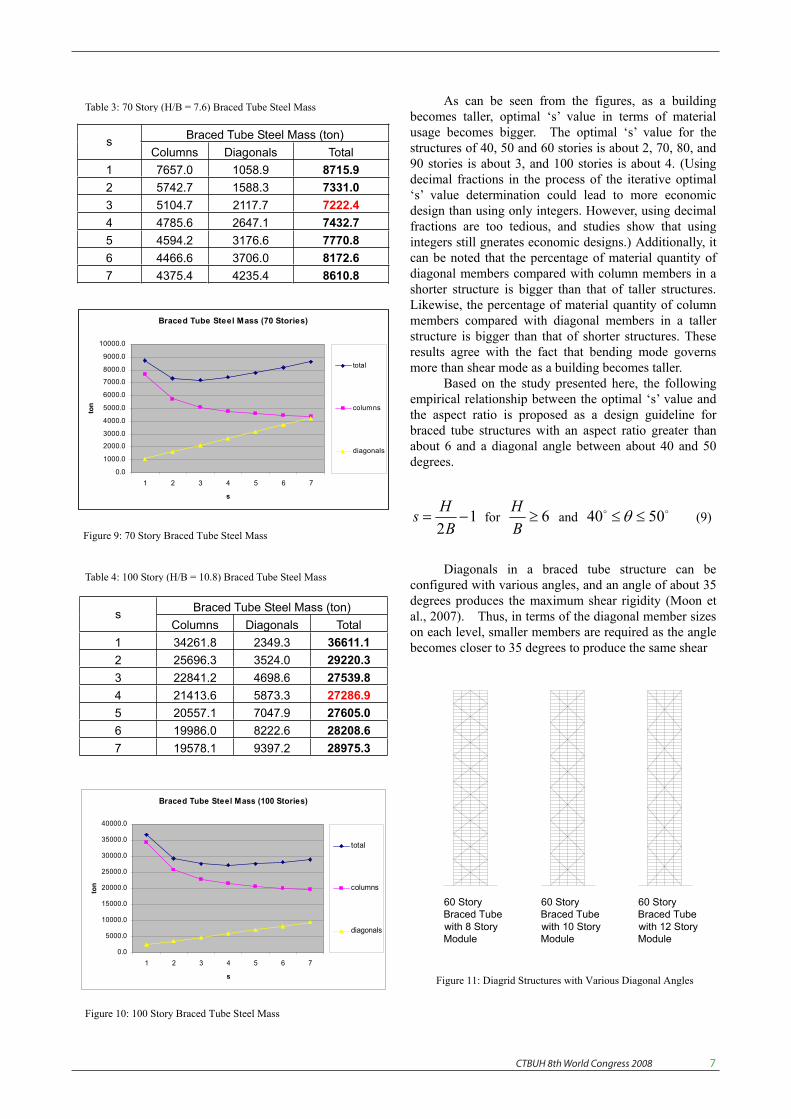
As can be seen from the figures, as a building becomes taller, optimal ‘s’ value in terms of material usage becomes bigger. The optimal ‘s’ value for the structures of 40, 50 and 60 stories is about 2, 70, 80, and 90 stories is about 3, and 100 stories is about 4. (Using decimal fractions in the process of the iterative optimal ‘s’ value determination could lead to more economic design than using only integers. However, using decimal fractions are too tedious, and studies show that using integers still gnerates economic designs.) Additionally, it can be noted that the percentage of material quantity of diagonal members compared with column members in a shorter structure is bigger than that of taller structures. Likewise, the percentage of material quantity of column members compared with diagonal members in a taller structure is bigger than that of shorter structures. These results agree with the fact that bending mode governs more than shear mode as a building becomes taller.
Based on the study presented here, the following empirical relationship between the optimal ‘s’ value and the aspect ratio is proposed as a design guideline for braced tube structures with an aspect ratio greater than about 6 and a diagonal angle between about 40 and 50 degrees.
12BHs for 6
BH
and 5040 (9)
Diagonals in a braced tube structure can be configured with various angles, and an angle of about 35 degrees produces the maximum shear rigidity (Moon et al., 2007). Thus, in terms of the diagonal member sizes on each level, smaller members are required as the angle becomes closer to 35 degrees to produce the same shear
Braced Tube Steel Mass (ton) sColumns Diagonals Total
1 34261.8 2349.3 36611.1 2 25696.3 3524.0 29220.3 3 22841.2 4698.6 27539.8 4 21413.6 5873.3 27286.9 5 20557.1 7047.9 27605.0 6 19986.0 8222.6 28208.6 7 19578.1 9397.2 28975.3
Braced Tube Steel Mass (70 Stories)
0.0
1000.0
2000.0
3000.0
4000.0
5000.0
6000.0
7000.0
8000.0
9000.0
10000.0
1 2 3 4 5 6 7
s
ton
total
columns
diagonals
Figure 9: 70 Story Braced Tube Steel Mass
Braced Tube Steel Mass (100 Stories)
0.0
5000.0
10000.0
15000.0
20000.0
25000.0
30000.0
35000.0
40000.0
1 2 3 4 5 6 7
s
ton
total
columns
diagonals
Figure 10: 100 Story Braced Tube Steel Mass
60 Story Braced Tube with 8 Story Module
60 Story Braced Tube with 10 Story Module
60 Story Braced Tube with 12 Story Module
Figure 11: Diagrid Structures with Various Diagonal Angles
Table 3: 70 Story (H/B = 7.6) Braced Tube Steel Mass
Table 4: 100 Story (H/B = 10.8) Braced Tube Steel Mass

CTBUH 8th World Congress 2008 �
rigidity. However, smaller member sizes at each level do not guarantee the overall least amount of material use. While the diagonal member sizes become smaller as the angle nears 35 degrees, the total length of all diagonals decreases as the angle approaches the vertical. In this study so far, structures with a 10 story module having a 47.3 degree diagonal angle were designed. Additional models with different module heights and diagonal angles were created to investigate the impact of the changing angles. For the 60 story braced tube structure, two additional models, which are composed of 8 and 12 story modules having 40.9 and 52.4 degree diagonal angles respectively, were designed (Figure 11). The study showed that the braced tube with a diagonal angle of 47.3 degrees uses 1.2% less diagonal material than with a diagonal angle of 40.9 degrees, and 6.5% less diagonal material than with a diagonal angle of 52.4 degrees. Thus, it can be concluded that the angle of about 45 degrees, which is typically used for tall buildings to satisfy both architectural and structural requirements in practice, is close to optimal angle in terms of minimum material usage.
All the presented structures with “preliminary” design members were analyzed using SAP2000. There is reasonably close agreement with only about maximum 5% difference between the maximum deformations targeted and obtained from SAP2000 analysis. Most of the members in these designs passed the SAP2000 LRFD code check, verifying that lateral stiffness generally controls the design for tall structures having an aspect ratio (H/B) greater than about six.
Design Studies of Diagrid Structures The stiffness based design methodology is now
applied to 40, 50, 60, 70, 80, 90 and 100 story diagrid structures, with an aspect ratio ranging from 4.3 to 10.8. The building’s plan dimensions are 36 meters by 36 meters, and its typical story height is 3.9 meters. All the required lateral stiffness is allocated to the perimeter diagrids, and consequently core structures are assumed to carry only gravity loads in this study. The buildings are assumed to be in Chicago, and the maximum lateral displacement, H/500 = 0.48 meters, is used as a motion parameter. Other design conditions are the same as those for the previous braced tubes.
In the braced tube structures, the optimal angle for the diagonals is independent of the building height because the diagonals primarily carry shear only. However, in the diagrid structures, diagonals carry both
shear and moment. Thus, the optimal angle of diagonals is highly dependent upon the building height. Since the optimal angle of the columns for maximum bending rigidity is 90 degrees and that of the diagonals for maximum shear rigidity is about 35 degrees, it is expected that the optimal angle of diagonal members for diagrid structures will fall between these angles and as the building height increases, the optimal angle also increases. Thus, the optimal design study for each story height diagrid structure was carried out with four different cases having angles of 52, 63, 69 and 73 degrees (Figure 12).
Member sizes for the modules were computed using Equations (3) and (4) customized for each design case.
2*
2*,
,
cos)6(2
cos2
hEVL
hENVLA
d
d
dwd
dwd
(3-1)
2*2
2*2,
,
sin)26(2
sin)(2
hEBML
hEBNMLA
d
d
ddfd
dfd
(3-2)
Both Nw (Number of Diagonals on Each Web Frame) and Nf (Number of Diagonals on Each Flange Frame) equal 6 in the particular design study case shown here. An estimate of the contribution of the diagonals on each web to the bending rigidity is made by adding one extra diagonal on each flange, resulting in 2d . To carry the shear forces and bending moments calculated using the code loadings, diagonal member sizes are increased from the top toward the bottom. As an example design, profiles of the required areas for the
52° 63° 69° 73°
Figure 12: Diagrid Structures with Various Diagonal Angles
Member Sizes for Bending & Shear (s=4)
0.0000
0.0500
0.1000
0.1500
0.2000
0.2500
57th
- 60
th
53rd
- 56
th
49th
- 52
nd
45th
- 48
th
41st
- 44
th
37th
- 40
th
33rd
- 36
th
29th
- 32
nd
25th
- 28
nd
21st
- 24
th
17th
- 20
th
13th
- 16
th
9th
- 12t
h
5th
- 8th
1st -
4th
stories
sq. m
eter
s
Ad for Bending
Ad for Shear
Figure 13: Preliminary Member Sizing for the 60 Story Diagrids

CTBUH 8th World Congress 2008 �
typical diagonals in the web and flange planes for the 60 story diagrid structure having a 69 degree diagonal angle are plotted with s=4 in Figure 13. Since the wind can blow in either direction, the role of a plane can be either a flange or a web. The building considered here has a square plan and the preliminary design value for the module is taken as the larger of the two values.
In order to find the optimal angle as well as the optimal deformation mode for a certain height diagrid structure, a set of structures having the four different diagonal angles shown in Figure 10 were designed for 40 through 100 story diagrid structures. For example, for 40 story diagrid structures, four different models having the four different angles were designed with various ‘s’ values. Among all the designs within the four sets, the one which uses the least amount of material is selected. The angle and ‘s’ value for that particular design is recorded as the optimal angle for a 40 story diagrid structure of a certain aspect ratio used here and as the optimal ‘s’ which produces the most desirable deformation mode respectively. Similar studies were repeated for 50, 60, 70, 80, 90, and 100 story diagrid structures. It was found that 63 degrees is near the optimal angle for the 40 and 50 story diagrid structures, and 69 degrees for the 60, 70, 80, 90, and 100 story diagrid structures. Various height diagrid structures configured with near optimal angle diagonals are shown in Figure 14.
Figures 15 through 17 show the results of this study for the 40, 70 and 100 story structures. (The results of the other story height structures, such as 50, 60, 80 and 90 story structures, are omitted here.) As can be seen from the figures, as a building becomes taller, optimal ‘s’ values in terms of material usage becomes bigger, as was the case in the former braced tube structures study. However, in diagrid structures, the
increase of ‘s’ values with regard to the increase of the height of the structure is much more rapid. The optimal ‘s’ value for the diagrid structure of 40 stories is 4, which is greater than the ‘s’ value of 2 for the braced tube structure. And, the optimal s value for the structure of 70 stories and 100 stories is 6 and 10 respectively, which are again greater than ‘s’ values of 3 and 4 for the braced tube structures of the same heights and aspect ratios. These results agree with the general fact that bending mode governs more than shear mode as a building becomes taller, and reflect the unique characteristics of the diagrid structures, which are different from more conventional braced tube structures. If bending rigidity is compared between a braced tube and diagrid structure of the same height and aspect ratio studied here, bending rigidity provided by vertical columns of a braced tube is much greater than that provided by inclined columns (diagonals) of the diagrid. With regard to shear rigidity, there are more diagonal members within a structural module in the diagrid structure than in braced tubes. Thus, diagrid structures provide greater shear rigidity. Buildings naturally tend to act as bending beams as they become taller. For the braced tube structures, it was noted that the percentage of material quantity of vertical column members compared with diagonal members in a taller structure is bigger than that in shorter structures. In the diagrid structures designed here, there are no vertical columns, and, thus, bending was carried by the perimeter diagonals, which are more effective in carrying shear on the web planes than carrying bending on the flange planes. This explains the rapid increase of optimal ‘s' numbers as a diagrid structure becomes taller. Even though the angles of diagonals substantially affect the shear rigidity and the angle of diagonals in the braced tube structure is closer to the optimal angle in terms of shear rigidity than in diagrid structures, the effect of more diagonals (in the order of several times) in a structural module surpass the angle effect.
Based on these studies, the following empirical relationship between the optimal ‘s’ value and the aspect ratio is proposed for diagrid structures greater than 40
Figure 14: Diagrid Structures of Various Heights with Optimal Angles
40 Storieswith 63 DegreeAngle
50 Storieswith 63 DegreeAngle
60 Storieswith 69 DegreeAngle
70 Storieswith 69 DegreeAngle
80 Storieswith 69 DegreeAngle
90 Storieswith 69 DegreeAngle
100 Storieswith 69 DegreeAngle
Figure 15: 40 Story Diagrid Steel Mass
Diagrid Steel Mass (40 Stories)
0
200
400
600
800
1000
1200
1400
1 2 3 4 5 6 7 8 9 10
s
ton

CTBUH 8th World Congress 2008 �0
stories with an aspect ratio greater than about 6 and a diagrid angle close to the optimal angle, which usually occurs between 60 and 70 degrees. This ‘s’ value is two times greater than that of Equation (9).
2BHs for 6
BH
and 7060 (12)
All the presented structures having “preliminary” design members were analyzed using SAP2000. All designs are conservative due to the characteristics of the
methodology presented here. When the near optimal ‘s’ value is used, there is reasonably close agreement with only about maximum 6% less deformation obtained by SAP2000 than the deformation targeted. Most of the members in these designs passed the SAP2000 LRFD code check, verifying that lateral stiffness generally controls the design for tall structures having an aspect ratio (H/B) greater than about six.
Premium for Heights As was realized first by Fazlur Khan, as buildings
become taller, there is a “premium for height” due to lateral loads and the demand on the structural system dramatically increases. As a result, the total structural material consumption increases drastically (Ali and Moon, 2007). Figure 18, which shows a summary of the studies presented here, illustrates this phenomenon. In both braced tube and diagrid structures, as building height increases, the quantity of the major lateral load resisting structural material increases not proportionally but drastically. This premium for heights clearly indicates the importance of material-saving design strategies in tall buildings presented here.
Braced Tube vs. Diagrid Structures Both braced tubes and diagrids are very efficient
systems for tall building structures. In this particular
Figure 16: 70 Story Diagrid Structure Steel Mass
Figure 17: 100 Story Diagrid Steel Mass
Diagrid Steel Mass (70 Stories)
0
2000
4000
6000
8000
10000
12000
1 2 3 4 5 6 7 8 9 10 11 12
s
ton
Diagrid Steel Mass (100 Stories)
0
10000
20000
30000
40000
50000
60000
1 2 3 4 5 6 7 8 9 10 11 12 13 14 15 16 17 18 19 20
s
ton
Figure 18: Premium for Heights
Material Usage Difference b/w Braced Tube and Diagrid
0
5000
10000
15000
20000
25000
30000
40stories
50stories
60stories
70stories
80stories
90stories
100stories
Building Story Heights
Ton
Braced Tube Steel Mass Diagrid Steel Mass

CTBUH 8th World Congress 2008 ��
study, the diagrid structures of 80 stories and below use less structural material than the braced tube structures of the same stories and aspect ratios. For the 90 story structures, both structures use almost identical quantities of structural material. For the 100 story structures, the braced tube structure uses less structural material than the diagrid structure, and it is expected to be valid for the taller structures based on the trend shown in Figure 18. The plan dimensions of the building studied here are relatively small, resulting in a large height-to-width aspect ratio. In addition, the design methodology for diagrids is more conservative than for braced tubes. Thus, in more general cases, diagrid structures will use less material than conventional braced tube structures even up to 100 story structures. Material usage difference between the braced tubes and diagrid structures studied here are summarized in Table 5.
Table 5: Material Usage Difference b/w Braced Tubes and Diagrids
Building Story
Heights
BracedTube Steel Mass (ton)
Diagrid Steel Mass(ton)
Material Usage Difference b/w Braced Tube
and Diagrid (%)
40 stories 989 821 20.5 50 stories 2128 1855 14.7 60 stories 4113 3822 7.6 70 stories 7222 6882 5.9 80 stories 11848 11574 2.4 90 stories 18545 18412 0.7
100 stories 27287 27703 -1.5
Conclusion The effectiveness and efficiency of tall building
structural systems with diagonals was discussed focusing on braced tubes and more recently-developed diagrids. Then, the stiffness-based design methodologies for determining preliminary member sizes for these structural systems were introduced and applied to a representative set of steel buildings. Results for displacement and required steel tonnage demonstrate the practical usefulness of the preliminary design method. Empirical guidelines for assessing the relative contribution of bending and shear deformation to the total lateral displacement of the systems for optimal designs were derived. With these formulas, the preliminary member sizing process is essentially automated, and the optimal designs, which use the least amount of structural material, are accomplished. Compared with a conventional iterative methodology, the proposed methodology is more efficient for today’s relatively light and flexible tall buildings, the design of which is in many cases governed by stiffness rather than strength.
This study also examined the influence of the geometric configurations of braced tube and diagrid structures. It was found that, for braced tube structures, the typically adopted angles in practice ranging from
about 40 to 50 degrees are closer to the optimal angle. In diagrid structures, as a building becomes taller, the optimal angle also becomes steeper within the typical range of about 60 to 70 degrees. The author expects that the stiffness-based design methodology and other topics discussed here will be very helpful to engineers for material-saving design of tall building structures.
References ALI, M. M. and MOON K. (2007). Structural Developments in Tall Buildings: Currents Trends and Future Prospects. Architectural Science Review, Vol. 50.3, pp 205-223. CONNOR, J. J. (2003). Introduction to Structural Motion Control.New York: Prentice Hall. MOON, K. (2005). Dynamic Interrelationship between Technology and Architecture in Tall Buildings. Ph.D. Dissertation, Department of Architecture, Massachusetts Institute of Technology, Cambridge, MA.MOON, K., CONNOR, J. J. and FERNANDEZ, J. E. (2007). Diagrid Structural Systems for Tall Buildings: Characteristics and Methodology for Preliminary Design, The Structural Design of Tall and Special Buildings, Vol. 16.2, pp 205-230. KOWALCZYK, R., SINN, R., and KILMISTER, M. B. (1995). Structural Systems for Tall Buildings. Council on Tall Buildings and Urban Habitat Monograph. New York: McGraw-Hill. SCHUELLER, Wolfgang. (1990). The Vertical Building Structure.New York: Van Nostrand Reinhold. http://www.hearst.com/tower/facts