mat e 272 - flaney associates€¦ · mat e 272 fall 2001 – midterm review ... rhombohedral...
TRANSCRIPT

1
Mat E 272Fall 2001 – Midterm Review
Tuesday October 9, 2001
Homework assignments:
• Set # 3 is being returned today and will be discussed in class
• Set #4 is due one week from today (October 16)
(the 3 graded problems are identified (7.5, 7.17, and 7.33) These only requirea short answer; please do these before the midterm on Thursday)
• Set # 5 will be due October 23; the problems will be posted on the web by the endof this week
Reading assignments:
• Week 8: we will discuss fatigue and failure first (Tuesday October 16) so readChapter 8 (excluding 8.10)
• Chapter 9 (phase diagrams) will be discussed Thursday October 18 andcontinuing on Tuesday October 23.
Chapter 2:
Metals: Materials characterized by high density of de-localized electrons (metallicbonding)Examples: Cu, Zn, Fe, Ti, Ag, Pt, brass, steel, monel,…
Ceramics: Materials characterized by covalent &/or ionic bonding Examples: silica (quartz), alumina, silicon carbide
Polymers: Organic materials, generally consisting of covalently-bonded hydrocarbonsExamples: nylon, polystyrene, polyethylene, polyester
Composites: Materials consisting of more than one distinct phase or component • engineered for specific applications (high strength – low density, high
strength – high conductivity, etc.)• usually strong (by design) (fiberglass: glass fibers strength and polymer
matrix formability)
Semiconductors: Materials characterized by electronic conduction intermediate between metalsand ceramics (e.g., Si, Ge, GaAs, InP)

2
Chemical bonding:
Electronegativity – the tendency for an atom to accept an electron
high electronegativity strong tendency to accept an electron (i.e., Group VIIA:F, Cl)
low electronegativity (called “electropositive”) strong tendency to give up anelectron, i.e., Group IA: Li, Na, K)
the difference in electronegativity between two atoms determines the resultingelectron distribution and the type of bond
Equilibrium separation between atoms:
ASYMMETRY of the potential vs. distance curve is due to differing relative strengths ofthe attractive and repulsive forces
THIS IS THE REASON FOR THERMAL EXPANSION
(slope of force vs. distance curve at equilibrium separation = modulus ofelasticity)
Bonding energy: Minimum of the potential vs. distance curveIndicates how much energy must be supplied to completely disassociate
the two atoms Depth of the potential well indicates bonding strength
Deep well strongly bondedShallow well weakly bonded
Bonding types
Primary
1. Ionic: Electron transfer from one atom (cation) to the other (anion)More likely between atoms with large electronegativity differencesTypically found between metal and non-metal atoms:
NaCl, KF, CsBr, MgO
Charge transfer results in electrostatic attraction between cations andanions:

3
Typical characteristics of ionically-bonded materials:High melting temperatureHardBrittleInsulator (electrical and thermal)
2. Covalent: electron sharing between atomshighly directional
fixed orientation of the atomsShared electrons may be considered to belong to each atom
Each atom tries to achieve a more stable orbital fillingconfiguration
Found in such diverse materials as diamond, silicon, SiC, GaAs, H2O, &many organic compounds (CH4, HNO3, HF)
• MOST MATERIALS ARE NEITHER 100% IONIC NOR100% COVALENT
3. Metallic: Ion cores are held together by electrostatic attraction with a “sea”of free electronsMore likely between atoms with large electronegativity differencesValence electrons are not bound to any specific atom…“free” to drift throughout the material (subject to local and externalelectromagnetic fields)
Secondary bonding (~ 10 kJ/mole or 0.1 eV/atom)
Van der Waals
charge polarization (dipoles)Thermal vibration fluctuations can disrupt charge symmetryThe presence of one dipole can induce a dipole in an adjacent molecule (oratom) and so on.
Permanent diploes: called POLAR molecules
Examples: water, ammonia, hydrogen fluoride

4
Chapter 3: Crystal Structure, Directions, and Planes
Atomic structure relates to the number of protons and neutrons in the nucleus of an atom, aswell as the number and probability distributions of the constituent electrons.
Crystal structure pertains to the arrangement of atoms in the crystalline solid material.
Crystal = point lattice (framework or basis) + atoms
A unit cell is the smallest entity that exhibits the chemical and crystallographic properties ofthe material.
the length of each unit cell axis is called a lattice parameter
In cubic systems, all three orthogonal lattice parameters are equal
Lattice parameters are typically on the order of a few Angstroms (or a few tenthsof a nanometer)
# atoms per unit cell:
The number of atoms/unit cell is an important quantity and determines many physicalproperties (thermal conductivity)
In general, the number of atoms/unit cell, N, is given by
82cf
iNN
NN ++= , where Ni = # interior atoms, Nf = # face atoms, Nc= # corner
atoms
there are 7 distinct crystal systems and 14 Bravais lattice types:
Crystal system Types of possible lattice arrangements
Cubic SC, BCC, FCCHexagonal HCPTetragonal Simple, body-centeredOrthorhombic Simple, base-centered, body-centered, face-centeredRhombohedral SimpleMonoclinic Simple, base-centeredTriclinic Simple
5
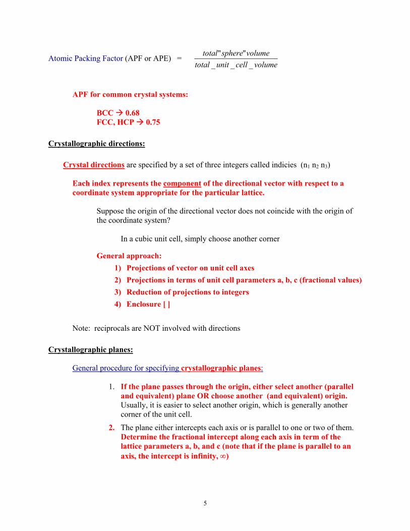
Atomic Packing Factor (APF or APE) = volumecellunittotal
volumespheretotal___
""
APF for common crystal systems:
BCC 0.68FCC, HCP 0.75
Crystallographic directions:
Crystal directions are specified by a set of three integers called indicies (n1 n2 n3)
Each index represents the component of the directional vector with respect to acoordinate system appropriate for the particular lattice.
Suppose the origin of the directional vector does not coincide with the origin ofthe coordinate system?
In a cubic unit cell, simply choose another corner
General approach:1) Projections of vector on unit cell axes2) Projections in terms of unit cell parameters a, b, c (fractional values)3) Reduction of projections to integers4) Enclosure [ ]
Note: reciprocals are NOT involved with directions
Crystallographic planes:
General procedure for specifying crystallographic planes:
1. If the plane passes through the origin, either select another (paralleland equivalent) plane OR choose another (and equivalent) origin.Usually, it is easier to select another origin, which is generally anothercorner of the unit cell.
2. The plane either intercepts each axis or is parallel to one or two of them.Determine the fractional intercept along each axis in term of thelattice parameters a, b, and c (note that if the plane is parallel to anaxis, the intercept is infinity, ∞)

6
3. Take the inverse (reciprocal) of each intercept. For this purpose, theinverse of infinity is zero.
4. Multiply each number by a common factor to reduce to the smallestset of integers.
5. Enclose the resulting set of number in parentheses: e.g., (001)
[ ] direction
< > family of equivalent directions
( ) plane
{ } family of equivalent planes
Close-packed directions:
Crystallographic directions corresponding to highest linear packing densityBCC: body diagonalsFCC: face diagonals
C-P directions correspond to direction of slip
Close-packed planes:
Crystallographic planes corresponding to highest areal packing densityInterplanar separation is greatest for C-P planesClose-packed planes in FCC metals are {111}:

7
Chapter 4 Imperfections in Solids
Examples of “defects:”
• addition of C to Fe to make steel• addition of Cu to Ni to make thermocouple wires• addition of Ge to Si to make thermoelectric materials• addition of Cr to Fe for corrosion resistance• introduction of grain boundaries to strengthen materials
In general, a defect simply refers to a disruption in the crystalline order of an otherwiseperiodic material.
1) one-dimensional (point)
vacancy
−=
kTQNN ov exp where Q is generally on the order of ~1 eV/atom
The quantity
o
v
NN is just the fraction of vacant lattice sites.
exp(-Q/kT) is a strong function of temperature
self-interstitial an atom from the crystal that crowds its way into an otherwiseempty void between atoms
impurity addition of an atom of a different species than the “host” or matrix
Alloys – other types of atoms are deliberately added to give thematerial certain properties
• May or may not result in the same crystal structure• May or may not result in secondary phases
solid solution
• A homogeneous distribution of two or moreelements.
• “solute” atoms are added without altering thecrystal structure or resulting in formation of a newphase.
• Solid solution is a particular type of alloy• Two types: substitutional and interstitial

8
There are very specific rules that govern the extent towhich solid solutions can form:
General guidelines for predicting solid solubility betweenany two elements:
For appreciable solubility to occur the following factorsmust be true:
• Atomic size factorthe difference in atomic radii between
the two atoms must be ≤ ± 15%• Electronegativity
the difference in electronegativity betweenthe two atoms must be ≤ ± 0.4
• Crystal structureThe crystal structure of each elementmust be the same
• ValenceFor a given solvent, a solute with ahigher valency is more likely to besoluble than one of lower valency,all other factors being equal.
Composition and conversion between weight and atomic percent:
Mixtures (i.e., composites) or alloys of two (or more) elements, arequantitatively described in terms of composition, either by weight percentor by atomic percent.
2) two-dimensional (linear)
Most common types of linear defect are dislocations, grain boundaries, twins, andexternal surfaces.
Dislocations: an extra half-plane of atoms in a crystal:
• Dislocations result from solidification from the melt, from mechanicalwork (e.g., rolling, swaging, drawing, compressive impact, tensile orshear stress), or from thermal stresses

9
• Dislocation motion is the primary mechanism responsible for thestrength and ductility behavior of metals
• From estimates of binding energy and atomic density, one cancalculate the theoretical strength of a metal
Result: observed strength <<< theoretical strength
Why the difference? Because the large-scale motion of atomsduring deformation is due to dislocation motion in a process calledslip
shear stresses cause atoms to slip by one atomic spacing
• Slip = movement of dislocations under the action of an applied stress• Slip planes are close-packed planes / slip occurs in close-packed
directions• Dislocations are not thermally stable
External surfaces
• atoms are in a high energy state• surface energy expressed in J/m3
• materials try to minimize surface energy
Grain boundaries
• interfacial region separating single crystalline volumes• usually only a few atoms wide• higher energy than bulk, but lower energy than external surface• many physical properties are determined by grain size
Twin boundaries:
• A disruption in the atomic stacking sequence• Results in a “mirror plane” symmetry:• Twins are formed during mechanical shear stresses (mostly BCC and
HCP metals) and during heat treatments (annealing twins – mostly inFCC metals)
3) three-dimensional (volumetric) defects
• second phase inclusions• porosity

10
• cracks
Chapter 5: Fundamentals of Diffusion
Diffusion: Transport in a solid, liquid, or gas driven by a concentration gradient (or,in the case of mass transport, a chemical potential gradient).
• The process of substitutional diffusion requires the presence of vacancies
• Factors that affect solid state diffusion:
• Diffusion occurs at a higher rate…
• at higher temperatures
• with smaller atoms
• in lower melting point host material
• in lower packing density host material
• in grain boundaries

11
• Steady state diffusion is described in terms of a flux and a concentrationgradient:
(steady state means the concentration gradient does not change with time,or that the flux into a unit area is equal to the flux leaving the area – noaccumulation or loss)
Flux = number (or mass) of atoms passing through an area per unit time
Two examples of units of flux:: sec2 ⋅cm
atoms or sec2 ⋅cm
grams
flux ∝ concentration gradient : xCJ∆∆
∝
or, dxdCDJ =
where the constant of proportionality (D) is called the diffusioncoefficient:
kTq
o
d
eDD−
=
2 primary mechanisms that affect flux:
• temperature (via diffusion coefficient)• slope of concentration gradient
• We usually don’t have steady state; more often, the concentration versusposition curve changes with time (non-steady state)
In this case, we must use another relationship Fick’s second
law: 2
2
dxCdD
dtdC
= , which describes diffusion in cases where the
concentration profile changes with time
• Solution to Fick’s 2nd law:
−=−−
Dtxerf
CCCC
os
ox
21

12
Cx = carbon concentration at any point “x” in the steel duringdiffusion,Co = initial (uniform) carbon concentration in the steel (at t = 0),Cs = surface concentration of carbon during diffusion
erf{} = “error” function: -1 < erf(x) < 1
The assumption that erf(x) ≅ x isn’t unreasonable for x <0.7. In situations where x > 0.7 or where erf(x) > 0.65, youshould really use the correct value:
• Important example: carburization (be familiar with examples)
Cx - CoCs - Co
= 1 - erf
x
2 Dt
• You should be comfortable working with and solving this equation forquantities like time, position, and composition.
• Make sure you review the examples in class and in the text• Interpolation isn’t required for this class but if the value of the
argument > 0.7, you should be able to look at the erf table and estimatea reasonable value for the function.

13
Chapter 6: Introduction to Mechanical Properties of Metals
• The quantity o
o
o lll
ll −=
∆is defined as the strain, ε,
where l = instantaneous lengthlo = initial length
• strain can also be reported as a percentage
• Strain is a dimensionless quantity (or, can be reported as m/m or in./in.)
• The quantity (F/A) is defined as the stress, σ,
where F is the load (pounds, N)A is the cross sectional area:
• If use Ao (initial area) engineering stress
• If use A (instantaneous area) true stress
• Engineering stress is more commonly used but can leadto misinterpretation of σ - ε curves.
• Elastic response:
In the elastic regime, the deformation is completely reversible, and we can write
oo llE
AF ∆
=
-or-
σ = E ε
The constant of proportionality, Young’s modulus or modulus of elasticity, is a measureof the material’s stiffness.

14
∆==
ollEEεσ so
Ell oσ
=∆ (elongation)
• Poisson’s ratio:
The ratio of lateral (εx, εy) to axial (εz) strain is known as Poisson’s ratio:
z
y
z
x
εε
εεν −=−=
• Plastic deformation:
Plastic ⇒ permanent (or non-recoverable) deformation
ε
σ
ε
σ
You should know whatthe key points on thestress – strain curve arecalled.

15
In ductile metals, the σ-ε curve eventually turns down after reaching the ultimatetensile strength (UTS). This does NOT mean that the material is becoming weaker.
Why? The gauge area decreases during plastic deformation due to necking.
• Since the actual cross-sectional area is reduced, use of the initial area gives a valuefor stress that is too high by the ratio (Ao/A)
• True (breaking or fracture) strength > tensile strength (but the engineering σ-εdiagram does not show this.
• Be able to work with a typical σ - ε curve such as the following
• Know how to calculate elastic modulus (−−
=∆∆
==12
12
εεσσ
εσslopeE ), maximum
loading, elongation

16
Other important mechanical properties:
• Ductility• Toughness• Hardness
Ductility:
• Ductility is a measure of how much strain a given stress produces.
Percent elongation:
100% xl
llEL
o
of
−=
where lo is the initial gauge lengthlf is the final gauge length at fracture
Since the magnitude of %EL depends on gauge length, youshould specify lo as well.
Percent reduction in area:
100% xA
AARA
o
fo
−=
where Ao is the initial cross sectional area (in the gauge section)Af is the final cross sectional area at fracture
Toughness:
• the amount of energy a material can absorb energy up to fracture.
• The units are energy per unit volume of material: J/m3
• Toughness requires both strength and ductility.
Hardness:
• the resistance to a localized applied plastic deformation.
• Mohs scale: relative ability of one material to scratch another

17
• Indentation methods are now commonly used:
• Brinell• Vickers• Knoop• Rockwell
• These all relate either depth or area of indentation to hardness

18
Chapter 7: Dislocations and Strengthening
• dislocation motion and interaction is the primary mechanism responsible forplastic deformation in metals.
• The presence of the dislocation results in local strain because the natural(equilibrium) spacing of the lattice is disrupted or distorted.
• Plastic deformation corresponds to the motion of large numbers of dislocations alongtheir respective slip planes.
• Slip only occurs in close-packed planes and only in close-packed directions.
• the movement of the dislocation requires the breaking (and formation) ofonly one set of bonds per step.
• The motion of edge or screw dislocations under the action of an applied shear stresscauses one atomic plane to slide over another, resulting in permanent (plastic)deformation.
• Dislocations are produced by :• solidification from the melt, • mechanical work (e.g., rolling, swaging, drawing, compressive impact, tensile
or shear stress), or • thermal stresses
• As a metal is plastically deformed:• the density of dislocations increases• they interact with each other.
• This interaction is responsible for the observed increase in strength• The movement of these dislocations is what enables plastic flow (or
slip) to occur in materials
• Dislocations move in close-packed directions within close-packed planes. • The combination of C-P plane (the slip plane) and C-P direction (the slip
direction) is called a slip system.
• The more slip systems available, the easier it is for dislocations to move, which is why(on the average) FCC and BCC metals are more ductile than HCP metals.
• For any given tensile axis, there is a greater probability in FCC and BCC metals thatsome slip systems are favorably oriented for slip to occur.

19
• Resolved shear stress
• the magnitude of the shear component is responsible for slip in any givenplane.
• The larger the shear component, the more likely slip will occur in that plane.
• plastic deformation occurs when τr = τCRSS
• τCRSS is a material property that determines the onset of plastic deformation.
Methods of Strengthening in Metals:
1) Grain boundaries act as a barrier to dislocation motion.
• 21
−+= dkyoy σσ
• more energy is required for a dislocation to cross grain boundaries,especially if high-angle
2) Plastic deformation (strain- or work-hardening)
• Dislocation motion is impaired by strain fields within a crystal.
• An increase in dislocation density ⇒ increase in number of repulsivestrain fields throughout the crystal ⇒ dislocation movement is hindered.
• increasing dislocation density increases strength
3) Solid solution strengthening
• a lattice strain results from the substitution of a different atom onto a givenlattice site.
• Tensile in the case of smaller solutes• Compressive in the case of larger solutes
• Lattice strain fields resulting from substitutional alloying interact with thedislocation strain fields and impede dislocation movement.
• Solute atoms tend to diffuse to the core of dislocations

20
• smaller atoms tend to occupy sites within the compressivestrain field above the slip plane.
• larger atoms tend to occupy sites within the tensile strain fieldbelow the slip plane
• Ceramics, as a rule, do not exhibit plastic deformation
• few, if any, active slip systems• interplanar sliding is not energetically favorable because of the distinct
charge distribution of the ions:
• If any plane tries to slip over an adjacent plane, ions of the samecharge would be brought closer together (electrostatic repulsion)
• Thus ceramics tend to be intrinsically strong but not very ductile
Recovery:
• Reduction in lattice strains by heat treatment• Recovery does not completely remove all lattice strains
• Can be useful in dissipating localized high stress regions that could lead tostress-corrosion problems.
Recrystallization:
• At sufficiently high temperatures, heavily cold-worked regions produce nuclei ofnew, stress-free grains.
• Mechanical properties of recrystallized metals are restored to their pre-coldworked state (weaker but more ductile).
• Recrystallization depends on both time and temperature.
• Metals are classified by their recrystallization temperature
• (temperature at which recrystallization just reaches completionin 1 hour)
• Rule-of-thumb: recrystallization temperature generally rangesfrom 33% to 50% of the absolute melting temperature.
• Note that the recrystallization temperature for Pb, Sn, and Zn is belowroom temperature. This means that these metals will not work-hardenat room temperature.
• These materials continuously recrystallize during plasticdeformation (i.e., they do not work-harden)

21
Grain Growth:
• There exists a thermodynamic driving force to reduce excess grainboundary energy
• This process is called grain growth
• Grain growth is a diffusional process (which means that it has an explicittemperature dependence)
• Grain growth proceeds by the diffusion of atoms across grain boundaries:
• Large grains grow at the expense of small grains
• The direction of grain growth is always towards the center of curvature