master thesis conceptual lay-out of a small launcher527191/fulltext01.pdf · master thesis...
TRANSCRIPT
Master Thesis
Conceptual Lay-out of a Small Launcher
Student: Claire Ballard
Supervisor: Markus Jaeger, Astrium GmbH Bremen
From: 05.09.2011To: 25.02.2012

Abstract
The objective of this diploma thesis is to perform a conceptual lay-out of a small launcher. Re-quirements have been defined in order to realize this first preliminary study and design of a smalllauncher. In that frame, a MATLAB code has been written in order to simulate the rocket tra-jectories. An optimization program on launcher staging has been written as well. To validatethis code, the VEGA and Ariane 5 launchers have been used. Then from studies on existinglaunchers, simulations have been performed in order to find an optimum small launcher and lateron to design more precisely the small launcher. As a requirement an upper stage has been newlydesigned for the purpose of the study. At the end, two small launchers have been considered: athree-stage launcher using the Zefiro 23 as a first stage, the Zefiro 9 as a second stage, and anupper stage using a 3kN thrust engine; a two-stage launcher using the Zenit booster engine in thefirst stage, and an upper stage using a 22kN thrust engine.
This paper presents the method used to develop the small launcher and the results.
Claire Ballard: Conceptual Lay-out of a Small Launcher - i -

- ii - Claire Ballard: Conceptual Lay-out of a Small Launcher

Contents
Contents
Abstract i
List of Figures vii
List of Tables x
Nomenclature xi
Abbreviations xiii
1 Introduction 1
2 Small Launcher Basic Conditions 3
2.1 Mission and Requirements . . . . . . . . . . . . . . . . . . . . . . . . . . . . . . . . 3
2.2 Method . . . . . . . . . . . . . . . . . . . . . . . . . . . . . . . . . . . . . . . . . . 6
2.2.1 Stage research . . . . . . . . . . . . . . . . . . . . . . . . . . . . . . . . . . 6
2.2.2 Upper stage design . . . . . . . . . . . . . . . . . . . . . . . . . . . . . . . . 7
2.2.3 Matlab code . . . . . . . . . . . . . . . . . . . . . . . . . . . . . . . . . . . 8
2.2.4 Small launcher . . . . . . . . . . . . . . . . . . . . . . . . . . . . . . . . . . 8
3 Calculation Methods 11
3.1 Flight Physics . . . . . . . . . . . . . . . . . . . . . . . . . . . . . . . . . . . . . . . 11
3.1.1 Newtons equations of motion . . . . . . . . . . . . . . . . . . . . . . . . . . 11
3.1.2 Environment model . . . . . . . . . . . . . . . . . . . . . . . . . . . . . . . 13
3.2 Trajectory Basics . . . . . . . . . . . . . . . . . . . . . . . . . . . . . . . . . . . . . 14
3.2.1 Gravity turn trajectory . . . . . . . . . . . . . . . . . . . . . . . . . . . . . 14
3.2.2 Hohmann transfer . . . . . . . . . . . . . . . . . . . . . . . . . . . . . . . . 15
3.3 Optimization: Nelder-Mead Method . . . . . . . . . . . . . . . . . . . . . . . . . . 18
3.4 Functional Budget . . . . . . . . . . . . . . . . . . . . . . . . . . . . . . . . . . . . 21
3.4.1 Propellant budget . . . . . . . . . . . . . . . . . . . . . . . . . . . . . . . . 22
3.4.2 Propellant tank volume . . . . . . . . . . . . . . . . . . . . . . . . . . . . . 23
3.4.3 Helium budget . . . . . . . . . . . . . . . . . . . . . . . . . . . . . . . . . . 24
3.5 Structural Mass . . . . . . . . . . . . . . . . . . . . . . . . . . . . . . . . . . . . . . 26
3.5.1 Upper stage components . . . . . . . . . . . . . . . . . . . . . . . . . . . . . 27
3.5.2 Structural Mass Calculation Software Tool . . . . . . . . . . . . . . . . . . 28
4 Code Explanation 41
4.1 The Simulation Folder . . . . . . . . . . . . . . . . . . . . . . . . . . . . . . . . . . 41
4.2 The Optimization Folder . . . . . . . . . . . . . . . . . . . . . . . . . . . . . . . . . 45
Claire Ballard: Conceptual Lay-out of a Small Launcher - iii -

Contents
5 Code Validation 475.1 VEGA launcher simulation . . . . . . . . . . . . . . . . . . . . . . . . . . . . . . . 475.2 VEGA launcher simulation results . . . . . . . . . . . . . . . . . . . . . . . . . . . 485.3 Ariane 5 launcher simulation . . . . . . . . . . . . . . . . . . . . . . . . . . . . . . 495.4 Ariane 5 launcher simulation results . . . . . . . . . . . . . . . . . . . . . . . . . . 515.5 Discussion . . . . . . . . . . . . . . . . . . . . . . . . . . . . . . . . . . . . . . . . . 53
6 Results 556.1 Existing Stages . . . . . . . . . . . . . . . . . . . . . . . . . . . . . . . . . . . . . . 55
6.1.1 Solid stages . . . . . . . . . . . . . . . . . . . . . . . . . . . . . . . . . . . . 556.1.2 Liquid stage . . . . . . . . . . . . . . . . . . . . . . . . . . . . . . . . . . . . 57
6.2 Upper Stage Preliminary Design . . . . . . . . . . . . . . . . . . . . . . . . . . . . 586.3 3-stage launcher solution . . . . . . . . . . . . . . . . . . . . . . . . . . . . . . . . . 61
6.3.1 Initial values, constants and inputs . . . . . . . . . . . . . . . . . . . . . . . 616.3.2 Optimal launchers . . . . . . . . . . . . . . . . . . . . . . . . . . . . . . . . 626.3.3 The retained solution . . . . . . . . . . . . . . . . . . . . . . . . . . . . . . 666.3.4 The upper stage design . . . . . . . . . . . . . . . . . . . . . . . . . . . . . 666.3.5 3-stage launcher configuration . . . . . . . . . . . . . . . . . . . . . . . . . . 746.3.6 Small launcher simulation . . . . . . . . . . . . . . . . . . . . . . . . . . . . 81
6.4 2-stage Launcher Solution . . . . . . . . . . . . . . . . . . . . . . . . . . . . . . . . 836.4.1 Initial values, constants and inputs . . . . . . . . . . . . . . . . . . . . . . . 836.4.2 Optimal launcher . . . . . . . . . . . . . . . . . . . . . . . . . . . . . . . . . 846.4.3 The retained solution . . . . . . . . . . . . . . . . . . . . . . . . . . . . . . 866.4.4 The Zenit new design . . . . . . . . . . . . . . . . . . . . . . . . . . . . . . 866.4.5 The upper stage design . . . . . . . . . . . . . . . . . . . . . . . . . . . . . 906.4.6 The 2-stage launcher . . . . . . . . . . . . . . . . . . . . . . . . . . . . . . . 986.4.7 Small launcher simulation . . . . . . . . . . . . . . . . . . . . . . . . . . . . 104
7 Conclusion 109
Bibliography 113
A Thrust profile 115A.1 VEGA boosters thrust profile . . . . . . . . . . . . . . . . . . . . . . . . . . . . . . 115A.2 Ariane 5 boosters thrust profile . . . . . . . . . . . . . . . . . . . . . . . . . . . . . 116
B Functional Budget Calculation Tool 117
C MATLAB function files 119
D MATLAB Main file 123
E Fluid schematic 125
F Technical drawings 127
- iv - Claire Ballard: Conceptual Lay-out of a Small Launcher
List of Figures
List of Figures
2.1 Small launcher mission . . . . . . . . . . . . . . . . . . . . . . . . . . . . . . . . . . 3
2.2 Small launcher configurations . . . . . . . . . . . . . . . . . . . . . . . . . . . . . . 4
2.3 A basic performance calculation loop . . . . . . . . . . . . . . . . . . . . . . . . . . 5
2.4 A second performance calculation loop . . . . . . . . . . . . . . . . . . . . . . . . . 6
2.5 Optimum curves . . . . . . . . . . . . . . . . . . . . . . . . . . . . . . . . . . . . . 7
2.6 Method to find optimum small launcher . . . . . . . . . . . . . . . . . . . . . . . . 9
3.1 Frame of reference and forces acting on the rocket . . . . . . . . . . . . . . . . . . 12
3.2 The gravity turn trajectory . . . . . . . . . . . . . . . . . . . . . . . . . . . . . . . 15
3.3 The Hohmann transfer . . . . . . . . . . . . . . . . . . . . . . . . . . . . . . . . . . 16
3.4 Elliptical orbit characteristics . . . . . . . . . . . . . . . . . . . . . . . . . . . . . . 18
3.5 The Nelder-Mead algorithm . . . . . . . . . . . . . . . . . . . . . . . . . . . . . . . 19
3.6 Example of the simplex method in a two-dimension space . . . . . . . . . . . . . . 20
3.7 The different move possibilities in the Nelder-Mead method . . . . . . . . . . . . . 21
3.8 Propellant budget . . . . . . . . . . . . . . . . . . . . . . . . . . . . . . . . . . . . 22
3.9 Propellant tank volume . . . . . . . . . . . . . . . . . . . . . . . . . . . . . . . . . 24
3.10 Pressure budget . . . . . . . . . . . . . . . . . . . . . . . . . . . . . . . . . . . . . . 25
3.11 Maximum helium pressure . . . . . . . . . . . . . . . . . . . . . . . . . . . . . . . . 26
3.12 Main components of an upper stage . . . . . . . . . . . . . . . . . . . . . . . . . . 27
3.13 Tank configurations . . . . . . . . . . . . . . . . . . . . . . . . . . . . . . . . . . . 28
3.14 Structural mass inputs . . . . . . . . . . . . . . . . . . . . . . . . . . . . . . . . . . 29
3.15 Section level of the evaluated tank configuration . . . . . . . . . . . . . . . . . . . 31
3.16 Structural load . . . . . . . . . . . . . . . . . . . . . . . . . . . . . . . . . . . . . . 31
3.17 Tank geometry calculations . . . . . . . . . . . . . . . . . . . . . . . . . . . . . . . 33
3.18 Common bulkhead tank 1 components . . . . . . . . . . . . . . . . . . . . . . . . . 34
3.19 Ellipse characteristics . . . . . . . . . . . . . . . . . . . . . . . . . . . . . . . . . . 34
3.20 Spherical-Cylindrical tank 1 components . . . . . . . . . . . . . . . . . . . . . . . . 36
3.21 Common bulkhead tank 2 components . . . . . . . . . . . . . . . . . . . . . . . . . 37
3.22 Spherical-Cylindrical tank 2 components . . . . . . . . . . . . . . . . . . . . . . . . 38
4.1 Rocketdata file . . . . . . . . . . . . . . . . . . . . . . . . . . . . . . . . . . . . . . 42
4.2 Matlab code explanation . . . . . . . . . . . . . . . . . . . . . . . . . . . . . . . . . 44
4.3 Rocket trajectory . . . . . . . . . . . . . . . . . . . . . . . . . . . . . . . . . . . . . 45
4.4 Optimization loop description . . . . . . . . . . . . . . . . . . . . . . . . . . . . . . 46
5.1 Vega launcher simulation from 0km to the elliptical orbit . . . . . . . . . . . . . . 49
5.2 Vega launcher simulation from 0km to the circular orbit . . . . . . . . . . . . . . . 50
5.3 Vega launcher simulation, other characteristics . . . . . . . . . . . . . . . . . . . . 50
5.4 Ariane 5 launcher simulation from 0km to the elliptical orbit . . . . . . . . . . . . 52
5.5 Ariane 5 launcher simulation, other characteristics . . . . . . . . . . . . . . . . . . 52
Claire Ballard: Conceptual Lay-out of a Small Launcher - v -

List of Figures
6.1 Optimum curves for solid stages . . . . . . . . . . . . . . . . . . . . . . . . . . . . . 56
6.2 Optimum structural index curve and engine mass for liquid stage . . . . . . . . . . 57
6.3 Angle requirement geometry . . . . . . . . . . . . . . . . . . . . . . . . . . . . . . . 58
6.4 The upper stage design . . . . . . . . . . . . . . . . . . . . . . . . . . . . . . . . . 59
6.5 Engine mass as a function of the engine thrust . . . . . . . . . . . . . . . . . . . . 60
6.6 The structural mass as a function of propellant mass . . . . . . . . . . . . . . . . . 61
6.7 Propellant budget results for the upper stage of the 3-stage launcher . . . . . . . . 67
6.8 Tank volume results for the upper stage of the 3-stage launcher . . . . . . . . . . . 67
6.9 Pressure gas budget results for the upper stage of the 3-stage launcher . . . . . . . 68
6.10 MEOP Helium results for the upper stage of the 3-stage launcher . . . . . . . . . . 69
6.11 Axial fluxes, common bulkhead load bearing tank, 3-stage launcher . . . . . . . . . 71
6.12 Structural mass part 1, common bulkhead load bearing tank, 3-stage launcher . . . 71
6.13 Structural mass part 2, common bulkhead load bearing tank, 3-stage launcher . . . 72
6.14 Axial fluxes, common bulkhead non load bearing tank, 3-stage launcher . . . . . . 72
6.15 Structural mass part 1, common bulkhead non load bearing tank, 3-stage launcher 73
6.16 Structural mass part 2, common bulkhead non load bearing tank, 3-stage launcher 73
6.17 Axial fluxes, spherical-cylindrical, 3-stage launcher . . . . . . . . . . . . . . . . . . 74
6.18 Structural mass part 1, spherical-cylindrical, 3-stage launcher . . . . . . . . . . . . 75
6.19 Structural mass part 2, spherical-cylindrical, 3-stage launcher . . . . . . . . . . . . 75
6.20 The three-stage launcher architecture . . . . . . . . . . . . . . . . . . . . . . . . . . 77
6.21 3D drawing of the upper stage, 3-stage launcher . . . . . . . . . . . . . . . . . . . . 78
6.22 Section cut of the upper stage, 3-stage launcher . . . . . . . . . . . . . . . . . . . . 78
6.23 3-stage launcher simulation from launch pad to the elliptical orbit . . . . . . . . . 82
6.24 3-stage launcher simulation from launch pad to the circular orbit . . . . . . . . . . 82
6.25 3-stage launcher simulation, other characteristics . . . . . . . . . . . . . . . . . . . 83
6.26 Propellant budget results for the first stage of the 2-stage launcher . . . . . . . . . 87
6.27 Tank volume results for the first stage of the 2-stage launcher . . . . . . . . . . . . 88
6.28 Pressure gas budget results for the first stage of the 2-stage launcher . . . . . . . . 88
6.29 MEOP Helium results for the first stage of the 2-stage launcher . . . . . . . . . . . 89
6.30 Structural mass, Common bulkhead load bearing tank, first stage, 2-stage launcher 91
6.31 Propellant budget results for the upper stage of the 2-stage launcher . . . . . . . . 92
6.32 Tank volume results for the upper stage of the 2-stage launcher . . . . . . . . . . . 93
6.33 Pressure gas budget results for the upper stage of the 2-stage launcher . . . . . . . 94
6.34 MEOP Helium results for the upper stage of the 2-stage launcher . . . . . . . . . . 94
6.35 Axial fluxes, non load-bearing Common Bulkhead configuration, upper stage, 2-stage launcher . . . . . . . . . . . . . . . . . . . . . . . . . . . . . . . . . . . . . . . 96
6.36 Structural mass part 1, non load-bearing Common Bulkhead configuration, upperstage, 2-stage launcher . . . . . . . . . . . . . . . . . . . . . . . . . . . . . . . . . . 97
6.37 Structural mass part 2, non load-bearing Common Bulkhead configuration, upperstage, 2-stage launcher . . . . . . . . . . . . . . . . . . . . . . . . . . . . . . . . . . 97
6.38 Axial fluxes, Spherical-Cylindrical configuration, upper stage, 2-stage launcher . . 98
6.39 Structural mass part 1, Spherical-Cylindrical configuration, upper stage, 2-stagelauncher . . . . . . . . . . . . . . . . . . . . . . . . . . . . . . . . . . . . . . . . . . 98
6.40 Structural mass part 2, Spherical-Cylindrical configuration, upper stage, 2-stagelauncher . . . . . . . . . . . . . . . . . . . . . . . . . . . . . . . . . . . . . . . . . . 99
6.41 The two-stage launcher architecture . . . . . . . . . . . . . . . . . . . . . . . . . . 100
6.42 3D drawing of the upper stage, 2-stage launcher . . . . . . . . . . . . . . . . . . . . 101
6.43 Section cut drawing of the upper stage, 2-stage launcher . . . . . . . . . . . . . . . 101
6.44 2-stage launcher simulation from launch pad to the elliptical orbit . . . . . . . . . 106
6.45 2-stage launcher simulation from launch pad to the circular orbit . . . . . . . . . . 107
- vi - Claire Ballard: Conceptual Lay-out of a Small Launcher
List of Figures
6.46 2-stage launcher simulation, other characteristics . . . . . . . . . . . . . . . . . . . 107
A.1 Thrust profile of the different VEGA launcher boosters . . . . . . . . . . . . . . . . 115A.2 Thrust profile of the solid booster . . . . . . . . . . . . . . . . . . . . . . . . . . . . 116
B.1 Propellant budget excel sheet . . . . . . . . . . . . . . . . . . . . . . . . . . . . . . 117B.2 Tank volume excel sheet . . . . . . . . . . . . . . . . . . . . . . . . . . . . . . . . . 117B.3 Pressure budget excel sheet . . . . . . . . . . . . . . . . . . . . . . . . . . . . . . . 118B.4 Helium pressure excel sheet . . . . . . . . . . . . . . . . . . . . . . . . . . . . . . . 118
C.1 Atmospheric model function . . . . . . . . . . . . . . . . . . . . . . . . . . . . . . . 119C.2 Mass function . . . . . . . . . . . . . . . . . . . . . . . . . . . . . . . . . . . . . . . 119C.3 Local gravity function . . . . . . . . . . . . . . . . . . . . . . . . . . . . . . . . . . 120C.4 Reference area function . . . . . . . . . . . . . . . . . . . . . . . . . . . . . . . . . 120C.5 Newton’s equations of motion . . . . . . . . . . . . . . . . . . . . . . . . . . . . . . 121C.6 Newton’s equations of motion during the gravity turn . . . . . . . . . . . . . . . . 121
D.1 Main file (1/3) . . . . . . . . . . . . . . . . . . . . . . . . . . . . . . . . . . . . . . 123D.2 Main file (2/3) . . . . . . . . . . . . . . . . . . . . . . . . . . . . . . . . . . . . . . 124D.3 Main file (3/3) . . . . . . . . . . . . . . . . . . . . . . . . . . . . . . . . . . . . . . 124
E.1 Upper stage fluid schematic . . . . . . . . . . . . . . . . . . . . . . . . . . . . . . . 126
F.1 Upper stage technical drawing, 3-stage launcher . . . . . . . . . . . . . . . . . . . . 128F.2 Upper stage technical drawing 1, 2-stage launcher . . . . . . . . . . . . . . . . . . . 129F.3 Upper stage technical drawing 2, 2-stage launcher . . . . . . . . . . . . . . . . . . . 130
Claire Ballard: Conceptual Lay-out of a Small Launcher - vii -

List of Figures
- viii - Claire Ballard: Conceptual Lay-out of a Small Launcher

List of Tables
List of Tables
2.1 Possible configurations . . . . . . . . . . . . . . . . . . . . . . . . . . . . . . . . . . 9
3.1 Model constants . . . . . . . . . . . . . . . . . . . . . . . . . . . . . . . . . . . . . 14
5.1 Vega launcher characteristics . . . . . . . . . . . . . . . . . . . . . . . . . . . . . . 475.2 Results comparison with the DLR study . . . . . . . . . . . . . . . . . . . . . . . . 485.3 Stage 2 and 3 in comparison with the DLR study . . . . . . . . . . . . . . . . . . . 485.4 Ariane 5 launcher characteristics . . . . . . . . . . . . . . . . . . . . . . . . . . . . 515.5 Ariane 5 trajectory characteristics at stage burn-out . . . . . . . . . . . . . . . . . 51
6.1 Solid boosters characteristics . . . . . . . . . . . . . . . . . . . . . . . . . . . . . . 556.2 Liquid boosters characteristics . . . . . . . . . . . . . . . . . . . . . . . . . . . . . 576.3 Fairing Characteristics . . . . . . . . . . . . . . . . . . . . . . . . . . . . . . . . . . 596.4 Engine mass and thrust datas . . . . . . . . . . . . . . . . . . . . . . . . . . . . . . 606.5 Structural mass calculation with the 8kN and 16kN thrust engine . . . . . . . . . . 616.6 Optimum launchers . . . . . . . . . . . . . . . . . . . . . . . . . . . . . . . . . . . . 626.7 Characteristics of the chosen solid stages . . . . . . . . . . . . . . . . . . . . . . . . 636.8 Solution 1, Optimization on the gravity turn, upper stage and payload . . . . . . . 646.9 Solution 1, Optimization on gravity turn, stage 1, stage 2, upper stage . . . . . . . 646.10 Solution 2, Optimization on the gravity turn, upper stage and payload . . . . . . . 646.11 Solution 2, Optimization on the gravity turn, stage 1, stage 2, upper stage . . . . . 656.12 Solution 3, Optimization on the gravity turn, upper stage and payload . . . . . . . 656.13 Solution 3, Optimization on the gravity turn, stage 1, stage 2, upper stage . . . . . 656.14 Three-stage small launcher solution . . . . . . . . . . . . . . . . . . . . . . . . . . . 666.15 The 3kN thrust engine characteristics . . . . . . . . . . . . . . . . . . . . . . . . . 666.16 Tank geometrical characteristics, Common Bulkhead load bearing configuration . . 706.17 Tank geometrical characteristics, common Bulkhead non-load bearing configuration 716.18 Tank geometrical characteristics, spherical-cylindrical configuration . . . . . . . . . 746.19 Mass breakdown of the upper stage for the 3-stage launcher . . . . . . . . . . . . . 806.20 The three-stage launcher characteristics . . . . . . . . . . . . . . . . . . . . . . . . 816.21 Chosen liquid stages characteristics . . . . . . . . . . . . . . . . . . . . . . . . . . . 846.22 Liquid, Solution 1, Soyuz stage and liquid upper stage . . . . . . . . . . . . . . . . 846.23 Liquid, Solution 2, Zenit stage and liquid upper stage . . . . . . . . . . . . . . . . 856.24 Liquid, Solution 3, Zenit booster and liquid upper stage . . . . . . . . . . . . . . . 856.25 The 2-stage launcher solution . . . . . . . . . . . . . . . . . . . . . . . . . . . . . . 866.26 The Zenit booster characteristics . . . . . . . . . . . . . . . . . . . . . . . . . . . . 866.27 The 22kN thrust engine characteristics . . . . . . . . . . . . . . . . . . . . . . . . . 906.28 Tank geometrical characteristics, not load bearing common bulkhead configuration 966.29 Tank geometrical characteristics, spherical-cylindrical configuration . . . . . . . . . 966.30 Mass breakdown of the first stage for the 2-stage launcher . . . . . . . . . . . . . . 1036.31 Mass breakdown of the upper stage for the 2-stage launcher . . . . . . . . . . . . . 105
Claire Ballard: Conceptual Lay-out of a Small Launcher - ix -

List of Tables
6.32 The two stage launcher characteristics . . . . . . . . . . . . . . . . . . . . . . . . . 106
- x - Claire Ballard: Conceptual Lay-out of a Small Launcher

Nomenclature
Nomenclature
a Semi-major axis of the ellipse [m]axb Longitudinal acceleration [m/s2]ayb Lateral acceleeration [m/s2]ag Gravitational acceleration [m/s2]dsec Section diameter [m]e Ellipse eccentricity [−]g Gravitational acceleration [m/s2]g0 Gravitational acceleration at sea level [m/s2]h Specific angular momentum [m2/s]inc Inclination angle of the orbit [deg]kax Max. axial acceleration [−]klat Max. lateral acceleration [−]lsec Section length [m]m Spacecraft mass [kg]mdry Spacecraft dry mass [kg]mengine Engine mass [kg]mi Initial spacecraft mass [kg]mf Final spacecraft mass [kg]mfuel Fuel mass [kg]mfair Fairing mass [kg]mox Oxidizer mass [kg]mp Propellant mass [kg]m Mass flow rate [kg/s]nFax Axial load per perimeter [N/m]nM Bending moment per area [N/m]p Pressure [Pa]r Radius [m]ra Apogee radius [m]rp Perigee radius [m]t1 Gravity turn beginning time [s]t2 Gravity turn ending time [s]tb Burning time [s]v Spacecraft velocity [m/s]vcirc Circular orbit speed [m/s]ve Exhaust velocity [m/s]vell Elliptic orbit speed [m/s]vx Longitudinal velocity [m/s]vy Lateral velocity [m/s]Cl Lift coefficient [−]
Claire Ballard: Conceptual Lay-out of a Small Launcher - xi -

Nomenclature
Cd Drag coefficient [−]D Drag [N ]E Young modulus [N/m2]F Thrust [N ]G Gravitational constant [m3/(kg s2)]H Altitude [m]Isp Specific impulse [s]L Lift [N ]M Earth mass [kg]MR Mixture ratio [−]RE Earth Radius [m]R Gas perfect constant [J/(Kmol)]S Reference area [m2]SF Safety factor [−]SI Structural index [−]∆V Velocity change [m/s]V Volume [m3]Vull Ullage volume [m3]T Temperature [K]X Ground range [m]α Angle of attack [deg]ε Specific orbital energy [−]µ Gravitational parameter [m3/s2]γ Flight path angle [deg]γ0 gravity turn rate [deg/s]ρ Air density [kg/m3]ρ0 Air density at sea level [kg/m3]σ Yield stress [N/m2]θ Pitch angle [deg]
Indices
1 Stage 12 Stage 23 Stage 3cyl Cylinder tankdome Tank domef Fuelfair FairingHe Heliumox Oxidizerprop Propellantsec Sectionsph Spherical tankull Ullage
- xii - Claire Ballard: Conceptual Lay-out of a Small Launcher
Abbreviations
Abbreviations
BDVM burst disk passivation MMHBDVN burst disk passivation NTOBDM burst disk MMHBDN burst disk NTOBM branching manifold with filterCRVH fill and drain valve HeliumCRVM fill and drain valve MMHCRVN fill and drain valve NTOCVM check valve MMHCVN check valve NTOETF engine thrust frameFCV flow control valveFDV1 pressurant fill and drain valveFDV2 propellant fill and drain valveFDV3 feedline fill and drain valveFH helium filterHVO Helium Venting OrificeISPR I stage pressure regulatorIISPR II stage pressure regulatorLVM Latch valve MMHLVN Latch valve NTOMEOP maximum expected operating pressureMMH monomethylhydrazineNTO dinitrogen tetroxidePO priming orificePT redundant pressure transducersPV1 priming pyrovalvePV2 mainflow pyrovalvePV3 depletion pressure transducersPVAM pressure valve assembly (MMH)PVAN pressure valve assembly (NTO)PVH pyrovalve HeliumPVM pyrovalve MMHPVN pyrovalve NTORACS roll and attitude control systemRDCM vent valve MMHRDCN vent valve NTOTCA thrust chamber assemblyTCM thruster cluster moduleTH helium tankTM MMH tank
Claire Ballard: Conceptual Lay-out of a Small Launcher - xiii -
Abbreviations
TN NTO tankTSPM passivation exhaust device (MMH)TSPN passivation exhaust device (NTO)
- xiv - Claire Ballard: Conceptual Lay-out of a Small Launcher
Introduction
Chapter 1
Introduction
Miniaturized satellites represent the current forefront of space technology. Indeed, the progressin the area of structure and electronics has led to smaller satellites and thereby reduced the sizerequirements of launch vehicles. Nowadays, the current launchers are able to launch several satel-lites at once. For instance, the Ariane 5 payload is usually made up of two or three satellites.When a company wishes to set a satellite in orbit, this company has to wait for another companywhich would like to set a satellite as well; if not, the launch would be too expensive. Thereby, thetime schedule is a constraint and so the need to develop a small launcher stands to reason. Thedevelopment of a small launcher will produce more flexibility, reactivity and will reduce costs aswell. Furthermore, the trend seen in small launcher augmentation is to develop a small launcherbased on existing stage in order to use existing technologies and thereby to reduce the cost of anew development.
In that frame, the future development of a small launcher will reduce the launch cost and al-low time flexibility as well. Therefore, the objective of this master thesis is to do the conceptuallay-out of a small launcher. A conceptual lay-out of a new small launcher includes several aspects:a performance aspect which includes trajectory simulations, trajectory optimization and launcherstaging optimization, and a design aspect which includes stage preliminary design. The perfor-mance part in this master thesis is not based on a previous work, and so a special tool to simulateand optimize the trajectory has been developed. From the launcher characteristics, namely thethrust, specific impulse, propellant and structural mass, and by resolving the equations of motionsof a rocket in a later on defined frame of reference, the amount of payload this launcher can carryto a certain orbit can be found. That is why a special program has been developed to study thelauncher performances. Later, the design of the possible stages is based on work done by a studentduring his thesis [3]. In order to design a new stage, propellant and pressure gas budgets haveto be carried out as well as structural calculations. Those budgets and calculations are based onthe previous thesis, however improvements and changes have been made for the purpose of thisthesis.
This paper presents the conceptual lay-out of two small launchers: a three-stage launcher withtwo solid stages and one liquid upper-stage, and a two-stage launcher, both containing liquid fuel.
Claire Ballard: Conceptual Lay-out of a Small Launcher - 1 -

Introduction
- 2 - Claire Ballard: Conceptual Lay-out of a Small Launcher
Small Launcher Basic Conditions
Chapter 2
Small Launcher Basic Conditions
This chapter summarizes the mission and the requirements of the small launcher. The methodwhich has been set up in order to design the conceptual lay-out is also described.
2.1 Mission and Requirements
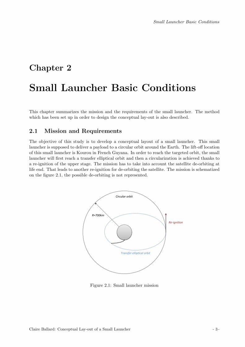
The objective of this study is to develop a conceptual layout of a small launcher. This smalllauncher is supposed to deliver a payload to a circular orbit around the Earth. The lift-off locationof this small launcher is Kourou in French Guyana. In order to reach the targeted orbit, the smalllauncher will first reach a transfer elliptical orbit and then a circularization is achieved thanks toa re-ignition of the upper stage. The mission has to take into account the satellite de-orbiting atlife end. That leads to another re-ignition for de-orbiting the satellite. The mission is schematizedon the figure 2.1, the possible de-orbiting is not represented.
Transfer ellip,cal orbit
Circular orbit
R=700km
Re-‐igni,on
Figure 2.1: Small launcher mission
Claire Ballard: Conceptual Lay-out of a Small Launcher - 3 -
Small Launcher Basic Conditions
For this study, several requirements have been imposed:
• The payload mass is between 100 and 250kg.
• The orbit is a circular polar orbit with a radius of 700km and an inclination of 90 degrees.
• An elliptical transfer orbit is reached first, and then a circularization is carried out.
• The small launcher can have 2 or 3 stages.
• The upper stage has to be designed with re-ignitable engines using liquid propulsion devel-oped by Astrium.
• The stages have to be existing ones or designed by using an engine developed by Astrium.
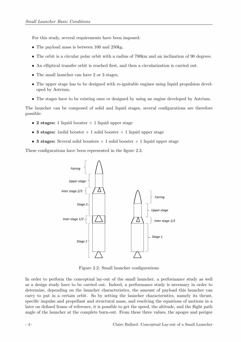
The launcher can be composed of solid and liquid stages, several configurations are thereforepossible:
• 2 stages: 1 liquid booster + 1 liquid upper stage
• 3 stages: 1solid booster + 1 solid booster + 1 liquid upper stage
• 3 stages: Several solid boosters + 1 solid booster + 1 liquid upper stage
These configurations have been represented in the figure 2.2.
Stage 1
Stage 2
Upper stage
Inter stage 2/3
Inter stage 1/2
Fairing
Upper stage
Stage 1
Inter stage 1/2
Fairing
Figure 2.2: Small launcher configurations
In order to perform the conceptual lay-out of the small launcher, a performance study as wellas a design study have to be carried out. Indeed, a performance study is necessary in order todetermine, depending on the launcher characteristics, the amount of payload this launcher cancarry to put in a certain orbit. So by setting the launcher characteristics, namely its thrust,specific impulse and propellant and structural mass, and resolving the equations of motions in alater on defined frame of reference, it is possible to get the speed, the altitude, and the flight pathangle of the launcher at the complete burn-out. From these three values, the apogee and perigee
- 4 - Claire Ballard: Conceptual Lay-out of a Small Launcher

Small Launcher Basic Conditions
Figure 2.3: A basic performance calculation loop
of the orbit can be calculated. At complete burnout, the spacecraft has to have a flight pathangle equal to zero and the right altitude and speed needed to stay in a certain orbit. The rocketis launch vertically, then at time t1 the rocket is turned by a maneuver called the gravity turntrajectory which will be defined later on, until a time t2, and then the rocket turns automaticallyby itself until burn-out. By changing these two times, the trajectory changes as well. So, if thelauncher characteristics are fixed, the performances of the launcher can be optimized by changingthese two times and the payload. The figure 2.3 illustrates this performance calculation.
However, the purpose of this study is to do the conceptual lay-out of a small launcher, andso to define all the characteristics of this launcher. Therefore, the characteristics are variablesas well as t1 and t2. However, if this study had to consider all the variables (thrust, specificimpulse, propellant mass, structural mass, t1 and t2) as independent variables, the problem wouldbe very complicated and would take a lot of time. In this study, one requirement is to use existingstages. Therefore, the launcher characteristics can not take all the possible values, furthermore,as the characteristics of the existing stages are known it is possible to relate some variables to onevariable. Indeed, by collecting existing launcher characteristics it is possible to obtain the variationof the structural index, the specific impulse and the thrust as a function of the propellant mass.By setting the propellant mass, the three others characteristics are automatically calculated. Inthat case, the launcher performances can be optimized by changing the amount of propellant andthe times t1 and t2. The figure 2.4 illustrates this second performance calculations.
It is important to notice that only the upper stage has its variables completely altered. Theupper stage characteristics have to be chosen in order to fulfill all the requirements. Therefore,design of this upper stage needs to be carefully considered. The amount of propellant, the thrustand the specific impulse will be chosen based on the performance study. In order to performthe design, a propellant and gas pressure budgets will be evaluated as well as structural calcula-
Claire Ballard: Conceptual Lay-out of a Small Launcher - 5 -

Small Launcher Basic Conditions
Figure 2.4: A second performance calculation loop
tions. To perform these budgets and calculate the structural mass, an existing tool will be used.Improvements will be made for the purpose of this study.
2.2 Method
This section explains the approach which has been decided in order to develop the small launcher.
2.2.1 Stage research
Research has been done on existing solid and liquid stages. A requirement in the developmentof the small launcher is that it must use existing liquid or solid stages. The research has beenfocused on stages with not too large a thrust value. From the research, the goal was to obtain theoptimum curves, e.g. the thrust, the specific impulse and the structure index as a function of thepropellant mass, as can be seen on the figure 2.5.The structural index is defined as the ratio between the structural mass and the total mass.
SI =ms
mp +ms(2.1)
where: mp propellant mass [kg]ms structural mass [kg]SI structural index [−]
- 6 - Claire Ballard: Conceptual Lay-out of a Small Launcher

Small Launcher Basic Conditions
mp
mp
mp
Thrust
Isp
SI
mp,
mp
mp
Figure 2.5: Optimum curves
2.2.2 Upper stage design
As can be seen from the requirements, the upper-stage has to be designed with a liquid propulsionengine developed by Astrium. So the second part of this study is to do a preliminary design onthe upper stage in order to run simulations later on. The design of the upper stage includes apropellant budget, a helium budget and structural mass calculations. Choices concerning the tankconfiguration, the material for the stage structure and tank structure, and the systems have to betaken. This engine with liquid propulsion is still under investigation at Astrium and it is not yetcommercially available, so some engine characteristics are still flexible. In that frame, the thrustis considered flexible and will be chosen based on the performance calculations.
The engine mass is directly linked to the thrust, whereas the stage structural mass is linkedto the propellant mass of the stage. As the propellant mass and the thrust are not fixed and willbe optimized, the structural mass is separated in two parts:
mdry,upperstage = mdry,w/o engine(mprop) +mengine(F ) (2.2)
• The structural mass, engine mass excluded, which depends on the propellant mass.
• The engine mass which depends on the the thrust engine.
In order to choose the characteristics of the upper stage in the small launcher, an optimizationwill be done on the amount of propellant and on the thrust.
Claire Ballard: Conceptual Lay-out of a Small Launcher - 7 -

Small Launcher Basic Conditions
Engine
The liquid propulsion engine in development at Astrium is a re-ignitable engine and uses thepropellant combination of MMH (monomethylhydrazine) and NTO (nitrogen tetroxide). Severalengines using these propellants are under investigation, and more precisely, studies with 3kN, 8kN,16kN, 22kN, 30kN and 50kN thrust engines have been done. From these studies, it is possible torelate the engine mass to the thrust.
Structure
At first, two different upper stages have been designed in order to determine the dependencybetween the structural mass and the propellant mass, and so to be able to run some simulations.These designs are a first estimation and have been done with margins, but at the end, the finalupper stage has been designed in more detail. To design the upper stage, an existing Excel tool wasavailable, some modifications have been done in order to improve the tool and will be explainedlater on.
2.2.3 Matlab code
A MATLAB code has been developed in order to simulate rocket trajectories by resolving numer-ically the equations of motion. This program enables the performance calculations to be done.By changing the variables it is possible to change the performance of the launcher. Later on, analgorithm is used in order to optimize the variables.
2.2.4 Small launcher
Then, simulations will be run in order to find an optimum launcher which meets all the require-ments. This launcher is called optimum launcher because the stage characteristics are directlycalculated from the optimum curves as defined previously, i.e. by choosing the amount of propel-lant, the thrust, specific impulse and structural index are automatically defined. The upper stagecharacteristics depend on the amount of propellant and the engine thrust. Two different methodswill be used depending on the characteristics of the launcher.
First configuration: two solid stages and a liquid upper stage
Simulations have been done for a three-stage launcher. The two first stages are solid boostersand the characteristics of these boosters are calculated thanks to the optimum curves representedin Figure 2.5. Thus, the thrust, the specific impulse and the structural index are functions ofthe propellant mass in the stage. By changing the propellant mass in one of the two stages thecharacteristics of this stage are automatically recalculated. The thrust and the propellant massof the upper stage are inputs and need to be optimized.
The purpose is to find optimum launchers by using the optimum curves, in order to see ifthe optimum launchers converge in the same direction. So, different amount of propellant foreach stage will be investigated. Only the amount of propellant is relevant, all the characteristicsof the stages are calculated thanks to the propellant mass of the considered stage. The differentamounts of propellant investigated for each stage are written in the table 2.1. In the first stage, thepropellant mass will be considered between 22,000 and 26,000kg, in the second stage, the propellantmass will be considered between 10,000kg and 12,000kg, in the third stage the propellant masswill be considered between 500kg and 1500kg, and the thrust, between 5kN and 15kN. That leadsto the study of 81 possible small launchers.
- 8 - Claire Ballard: Conceptual Lay-out of a Small Launcher

Small Launcher Basic Conditions
mp,1 [kg] 22,000 24,000 26,000mp,2 [kg] 10,000 11,000 12,000mp,3 [kg] 500 1,000 1,500T3 [N ] 5,000 10,000 15,000
Table 2.1: Possible configurations
In order to clarify, the method is schematized in Figure 2.6 as a tree. Each branch of the treewill be investigated and an optimum small launcher will be found from these initial characteristicsby using the optimization program.
Figure 2.6: Method to find optimum small launcher
Finally, from the optimum launchers, the purpose is to find the existing boosters which areclosest to the optimum results and so to focus only on a maximum of three boosters. Then, newsimulations have to be run in order to choose the existing boosters and to design the upper stageof the launcher in more detail.
Second configuration: a liquid stage and a liquid upper stage
Simulations will also be done for a two-stage launcher with two liquid stages. The method usedto design this launcher is different from the one used with the three-stage launcher. Indeed, theexisting liquid stages are either too big or they do not have enough thrust to lift the launcher.So the liquid stages need to be modified. This modification will be made on the stage structure.So, the method used is to pick first a liquid stage, to keep the thrust and the specific impulseas constants and to calculate the structural mass as a function of the propellant mass. So, forthe liquid stage, only the optimum curve concerning the structural index is relevant in this study.
Claire Ballard: Conceptual Lay-out of a Small Launcher - 9 -

Small Launcher Basic Conditions
By reducing the amount of propellant in the stage, and so by reducing the structural mass, thelauncher is capable of lift off. The purpose is to optimize the amount of propellant in the liquidstage whilst also achieving optimization of the upper stage (propellant mass and thrust).
- 10 - Claire Ballard: Conceptual Lay-out of a Small Launcher

Calculation Methods
Chapter 3
Calculation Methods
The objective of this thesis is to perform a conceptual lay-out of a small launcher. The methodused to perform the conceptual-lay-out has been explained in the previous chapter but in orderto understand, some theoretical fundamentals need to be defined and explained.The following chapter describes the theoretical fundamentals needed to perform a conceptuallay-out.
3.1 Flight Physics
As explained previously, the performance calculations are done by resolving the equations of mo-tion, and so these equations of motion and the frame of reference need to be introduced. Thefollowing part explains the flight physics which is essential to understand how the equations ofmotion are solved.
The forces acting on a rocket are the thrust, the aerodynamic forces, the gravitational attrac-tions, the wind and solar radiation pressure [1]. The two last forces are usually small and aretherfefore neglected. In this study, the rocket trajectory is considered two dimensional. Thisassumption has been made because the tool developed to simulate the rocket trajectory has tobe relatively simple and fast. Also this tool is used for making preliminary estimates and so atwo dimensional problem is enough for this study. Thus, the trajectory is two dimensional and iscontained in a fixed plane. The flight is assumed over a non-rotating spherical Earth [6].
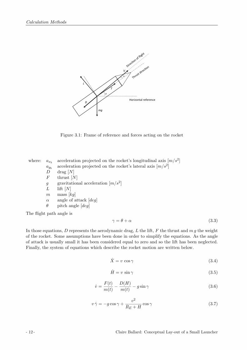
The body-fixed coordinate system is the frame of reference of the rocket. The x-axis corre-sponds to the longitudinal axis of the rocket, the y-axis is perpendicular to the x-axis in the lateralplane. This frame of reference is represented on the Figure 3.1, the forces acting on the rocket arealso represented, namely the drag D, the lift L, the weight mg and the thrust T .In Figure 3.1,α is the angle of attack, it is the angle between the direction of flight and the thrust direction; θis the pitch angle, it is the angle between the horizontal reference and the thrust direction. Thesum of these two angles is called the flight path angle γ.
The linear velocity due to the Earth rotation (in the orbital plane) is calculated for the startlocation from its latitude and orbit inclination.
3.1.1 Newtons equations of motion
The Newtons equations of motion considered in the body-fixed axis system are written below.
maxb = −D cosα− L sinα+ F cosα−mg sin θ (3.1)
mayb = −D sinα+ L cosα− F sinα−mg cos θ (3.2)
Claire Ballard: Conceptual Lay-out of a Small Launcher - 11 -
Calculation Methods
mg
L
D
T
V
θ
α
Horizontal reference
Figure 3.1: Frame of reference and forces acting on the rocket
where: axb acceleration projected on the rocket’s longitudinal axis [m/s2]ayb acceleration projected on the rocket’s lateral axis [m/s2]D drag [N ]F thrust [N ]g gravitational acceleration [m/s2]L lift [N ]m mass [kg]α angle of attack [deg]θ pitch angle [deg]
The flight path angle is
γ = θ + α (3.3)
In those equations, D represents the aerodynamic drag, L the lift, F the thrust and mg the weightof the rocket. Some assumptions have been done in order to simplify the equations. As the angleof attack is usually small it has been considered equal to zero and so the lift has been neglected.Finally, the system of equations which describe the rocket motion are written below.
X = v cos γ (3.4)
H = v sin γ (3.5)
v =F (t)
m(t)− D(H)
m(t)− g sin γ (3.6)
v γ = −g cos γ +v2
RE +Hcos γ (3.7)
- 12 - Claire Ballard: Conceptual Lay-out of a Small Launcher

Calculation Methods
where: D drag [N ]F thrust [N ]g gravitational acceleration [m/s2]H altitude [m]m spacecraft mass [kg]v spacecraft velocity [m/s]X ground range [m]γ spacecraft flight path angle [rad]
The expressions of the drag is written below.
D(H) = 0.5 ρ(H)S Cd v2 (3.8)
where: Cd drag coefficient [−]D drag [N ]H altitude [m]S reference area [m2]v spacecraft velocity [m/s]ρ air density [kg/m3]
The drag coefficient is a function of the local flow Mach number and the geometry of the rocket,but in this study it has been considered constant. This assumption has been done because thechanges in drag coefficient have no significative impact on the results of the simulation. Indeed,the local flow Mach number depends strongly on the geometry shape of the vehicle. Concerningthe rocket, the drag coefficient is typically constant and approximately equal to 0.3 in the subsonicand hypersonic flight phase. Around Mach 1, the drag coefficient is higher, about 0.5. Simulationshave been done with a constant drag coefficient equal to 0.3 and a non constant drag coefficient.The drag coefficient was set to 0.3 for a Mach number smaller than 0.9 and larger than 1.1, andequal to 0.5 for a Mach number between 0.9 and 1.1. These changes in the drag coefficient are notreal but the purpose was to see the impact on the simulation results. From two similar simulations,by changing only the drag coefficient as explained previously, it has been shown than there is nosignificant change on the simulation results. The velocity change is around 0.1% and the altitudechange is around 6%. So finally, no function for the drag coefficient has been implemented in thecode but it is a possibility to do so.
3.1.2 Environment model
The International Standard Atmosphere model is used. The equation 3.9 shows the dependencyin altitude of the air density.
ρ(H) = ρ0 exp(− HH0
) (3.9)
with
H0 =RT (H)
GM(3.10)
T (H) = T0 + aH (3.11)
Claire Ballard: Conceptual Lay-out of a Small Launcher - 13 -

Calculation Methods
where: a lapse rate [K/m]H0 scale height [m]H altitude [m]G gravitational constant [m3/kg s2]M molecular mass of air [kg/mol]R perfect gas constant [J/molK]T0 temperature at sea level [K]T local temperature [K]ρ0 density at sea level [kg/m3]ρ local density [kg/m3]
The local gravity is calculated with the following equation.
g = g0 (RE
RE +H)2 (3.12)
where: H altitude [m]g0 sea level gravity [m/s2]g local gravity [m/s2]RE Earth radius [m]
The following constants are implemented in the code:
Entity Value
Lapse rate [K/m] a -0.0065Gravity at sea level [m/s2] g0 9.80665Gravitational constant [m3/kg s2] G 3.9893 1014
Molecular mass of air [kg/mol] M 28.97 10−3
Temperature at sea level [K] T0 288Density at sea level [kg/m3] ρ0 1.29Perfect gas constant [J/molK] R 8.31432Earth radius [km] RE 6371
Table 3.1: Model constants
3.2 Trajectory Basics
3.2.1 Gravity turn trajectory
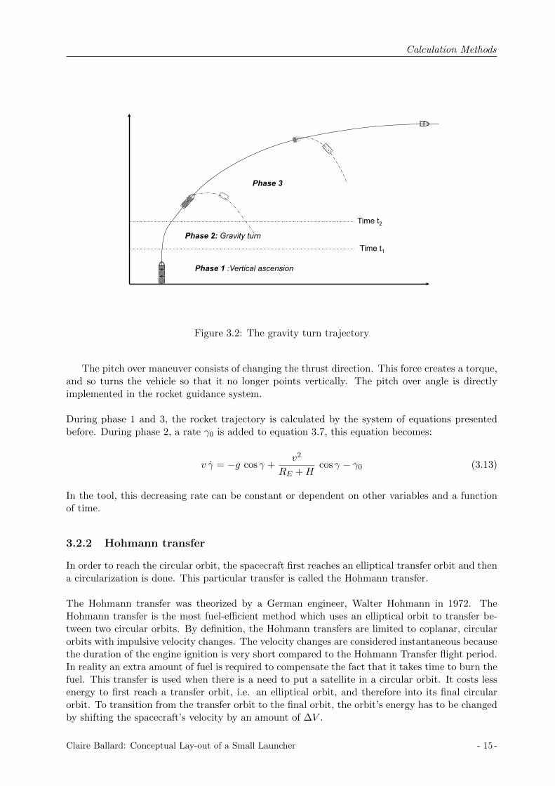
A launch vehicle typically starts its ascent with a vertical rise and in order to reach a horizontalposition at burnout, the vehicle has to turn and this is automatically done by dynamics, in what istermed a gravity turn trajectory, or the pitch over maneuver. The typical trajectory is representedin Figure 3.2. After the vertical rise, the vehicle is nudged during a certain amount of time in orderto reach a horizontal position at burnout. The pitch over maneuver has to be executed in orderto minimize the gravity losses, as during the vertical ascension the gravity directly acts againstthe thrust of the rocket, and also the pitch over should be applied when the vertical velocity issmall in order to reduce the aerodynamic losses during the maneuver [1].
- 14 - Claire Ballard: Conceptual Lay-out of a Small Launcher
Calculation Methods
Phase 1 :Vertical ascension
Phase 2: Gravity turn
Phase 3
Time t1
Time t2
Figure 3.2: The gravity turn trajectory
The pitch over maneuver consists of changing the thrust direction. This force creates a torque,and so turns the vehicle so that it no longer points vertically. The pitch over angle is directlyimplemented in the rocket guidance system.
During phase 1 and 3, the rocket trajectory is calculated by the system of equations presentedbefore. During phase 2, a rate γ0 is added to equation 3.7, this equation becomes:
v γ = −g cos γ +v2
RE +Hcos γ − γ0 (3.13)
In the tool, this decreasing rate can be constant or dependent on other variables and a functionof time.
3.2.2 Hohmann transfer
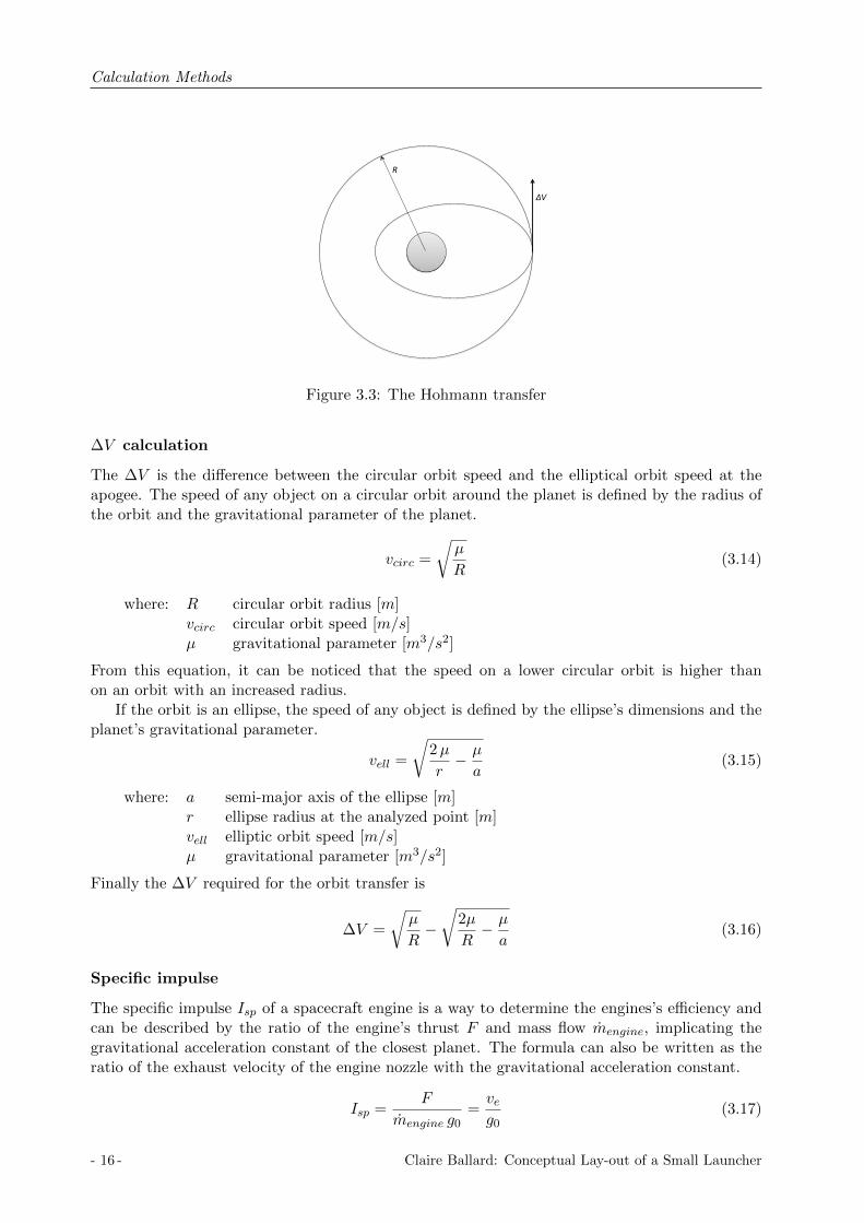
In order to reach the circular orbit, the spacecraft first reaches an elliptical transfer orbit and thena circularization is done. This particular transfer is called the Hohmann transfer.
The Hohmann transfer was theorized by a German engineer, Walter Hohmann in 1972. TheHohmann transfer is the most fuel-efficient method which uses an elliptical orbit to transfer be-tween two circular orbits. By definition, the Hohmann transfers are limited to coplanar, circularorbits with impulsive velocity changes. The velocity changes are considered instantaneous becausethe duration of the engine ignition is very short compared to the Hohmann Transfer flight period.In reality an extra amount of fuel is required to compensate the fact that it takes time to burn thefuel. This transfer is used when there is a need to put a satellite in a circular orbit. It costs lessenergy to first reach a transfer orbit, i.e. an elliptical orbit, and therefore into its final circularorbit. To transition from the transfer orbit to the final orbit, the orbit’s energy has to be changedby shifting the spacecraft’s velocity by an amount of ∆V .
Claire Ballard: Conceptual Lay-out of a Small Launcher - 15 -
Calculation Methods
ΔV
R
Figure 3.3: The Hohmann transfer
∆V calculation
The ∆V is the difference between the circular orbit speed and the elliptical orbit speed at theapogee. The speed of any object on a circular orbit around the planet is defined by the radius ofthe orbit and the gravitational parameter of the planet.
vcirc =
õ
R(3.14)
where: R circular orbit radius [m]vcirc circular orbit speed [m/s]µ gravitational parameter [m3/s2]
From this equation, it can be noticed that the speed on a lower circular orbit is higher thanon an orbit with an increased radius.
If the orbit is an ellipse, the speed of any object is defined by the ellipse’s dimensions and theplanet’s gravitational parameter.
vell =
√2µ
r− µ
a(3.15)
where: a semi-major axis of the ellipse [m]r ellipse radius at the analyzed point [m]vell elliptic orbit speed [m/s]µ gravitational parameter [m3/s2]
Finally the ∆V required for the orbit transfer is
∆V =
õ
R−√
2µ
R− µ
a(3.16)
Specific impulse
The specific impulse Isp of a spacecraft engine is a way to determine the engines’s efficiency andcan be described by the ratio of the engine’s thrust F and mass flow mengine, implicating thegravitational acceleration constant of the closest planet. The formula can also be written as theratio of the exhaust velocity of the engine nozzle with the gravitational acceleration constant.
Isp =F
mengine g0=veg0
(3.17)
- 16 - Claire Ballard: Conceptual Lay-out of a Small Launcher

Calculation Methods
where: F engine’s thrust [N ]g0 gravitational acceleration constant [m/s2]Isp specific impulse [s]mengine engine’s mass flow [kg/s]ve exhaust velocity [m/s]
The higher the specific impulse is, the higher the thrust is for the same amount of propellant. Thespecific impulse indicates which rocket is the most efficient when comparing rockets.
Tsiolkovsky equation
The Tsiolkovsky equation is a basic equation in astronautics which describes the velocity changeof a spacecraft after a maneuver by relating it with the effective exhaust velocity and the initialand final total mass of the spacecraft before and after the maneuver.
∆V = ve ln(mi
mf) (3.18)
where: mi initial total mass [kg]mf final total mass [kg]ve exhaust velocity [m/s]∆V velocity change [kg]
From equation 3.18, it is possible to determinate the amount of propellant needed for the Hohmanntransfer maneuver. The initial total mass consists of the propellant mass needed for the maneuverand the final total mass: mi = mp +mf . The amount of propellant needed for the maneuver caneasily be derived:
mp = mf (exp(∆V
Isp g0)− 1) (3.19)
where: g0 gravitational acceleration constant [m/s2]Isp specific impulse [s]mf final total mass [kg]mp propellant mass [kg]∆V velocity change [kg]
Orbital characteristics
This part aims to explain characteristics of an ellipse orbit, and more precisely how to determinatethe apogee and perigee of an elliptical orbit. The elliptic orbit and its principal characteristics arerepresented in Figure 3.4. A point M on the orbit is represented by its radius from the focus andby its true anomaly θ.
The polar equation of the elliptic orbit is written in equation 3.20, it depends on the specificrelative angular momentum h, the eccentricity e and the true anomaly θ.
r =h2
µ
1
1 + e cos θ(3.20)
h = v cos(γ) r (3.21)
e =
√1 +
2 ε h2
µ2(3.22)
ε =v2
2− µ
r(3.23)
Claire Ballard: Conceptual Lay-out of a Small Launcher - 17 -

Calculation Methods
Perigee Radius, rp
Apogee Radius, ra
P A
Semi-‐major axis, a Foci
M
r
θ
Figure 3.4: Elliptical orbit characteristics
where: e eccentricityh specific angular momentum [m2/s]r ellipse radius [m]v velocity [m/s]ε specific orbital energyγ flight path angle [rad]µ gravitational parameter [m3/s2]θ true anomaly [rad]
From equation 3.20, the longest distance from the foci, named the apogee (Equation 3.25) andthe shortest distance from the foci, named the perigee (Equation 3.24) can be easily calculated.
rp =h2
µ
1
1 + e(3.24)
ra =h2
µ
1
1− e(3.25)
Finally, by knowing the velocity, the flight path angle, the altitude of a spacecraft, the apogeeradius and perigee radius can be calculated.
3.3 Optimization: Nelder-Mead Method
In the performance calculations, in order to optimize the different variables, an algorithm hasbeen used: it is the Nelder-Mead algorithm which is presented in the following part.
The Nelder-Mead method is a nonlinear optimization technique. This method is based on theconcept of a simplex, which is a special polytope of N + 1 vertices in N dimensions. This methodapproximates a local optimum of a problem with N variables when the objective function variessmoothly [4]. As it is a local optimum, it is important to start the optimization with points alreadyclose to a good solution. This method has been chosen regarding the simplicity of the algorithmand mostly because of the need for smoothness in the solution. The algorithm is represented inFigure 3.5. The understanding of the algorithm in n dimensions can be difficult so in order tomake it clear, the explanation of the algorithm will be done in two-dimensional space.
- 18 - Claire Ballard: Conceptual Lay-out of a Small Launcher

Calculation Methods
x1, x
2, …
, xn
+1
Ord
er
f(x1)<
f(x2)<…
<f(x
n+1)
Cal
cula
te x
0 cen
ter o
f gr
avity
of a
ll po
ints
ex
cept
xn+
1
xr=2x
0-xn+
1
If f(x
1)<f(x
r)<f(x
n)
If f(x
r)<f(x
1)
f(xr)>
f(xn)
xn+1=x
r ye
s
xe=3
x0 –
xn+1
If f(x
e)<f(x
n+1)
yes
no
no
Yes:
xn+
1=xe
No:
xn+
1=xr
xc=x
0 –0.
5xn+
1
If f(x
c)<f(x
n+1)
yes
xn+1=x
c
xi=x1
–0.
5(xi
-x1)
i={2
, … ,
n+1}
no
Figure 3.5: The Nelder-Mead algorithm
Claire Ballard: Conceptual Lay-out of a Small Launcher - 19 -

Calculation Methods
Example in 2D
In a two-dimensional space, three vertices are required to find the optimum points by using thesimplex method. So, three points x1, x2 and x3 are considered. In two dimensions, those threepoints form a triangle. The objective function f is calculated for the three points, and so thepoints can be derived from the one which has the smallest objective function to the worst one,for instance considering f(x1) < f(x2) < f(x3). The point which has the worst objective functionis replaced by its reflected image in a mirror where the mirror is the segment formed with thetwo other points. A representation is done in Figure 3.6. In the first triangle the worst point isx3, the point is replaced and a second triangle is formed, the blue one. In this new triangle, theworst point is x1, the point is replaced and a new triangle is formed again, the green one. And soon, the points move in the space and converge to the optimum point. On the following figure, sixtriangles are represented.
x2x1
x3
x3x1
x3
x1 x2
1
2
3
4
5
6
Figure 3.6: Example of the simplex method in a two-dimension space
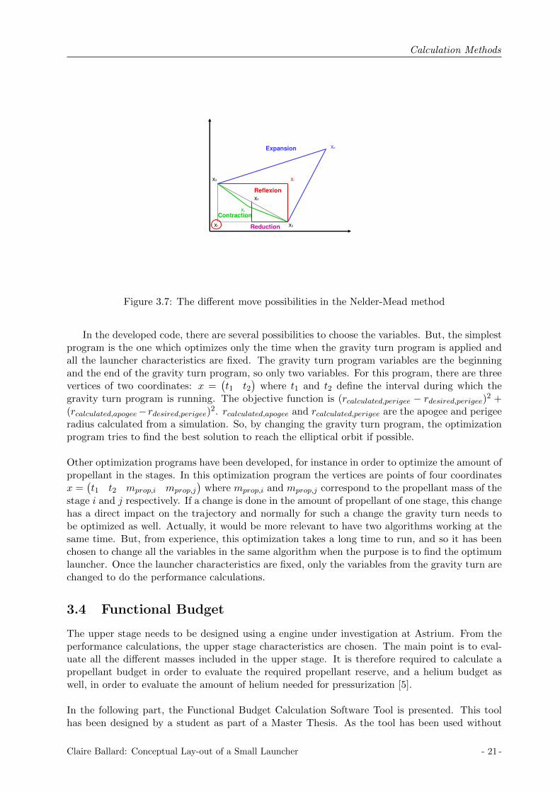
The Nelder-Mead algorithm is based on the simplex method as explained previously. Thedifferences are on the triangle change. In the simplex method, it is based on reflection, but in theNelder-Mead algorithm it is based on the reflexion, the expansion, the contraction or the reductiondepending on the objective function. These four triangle changes are represented in Figure 3.7.
The choice in the triangle is done as follows. The objective functions of the three points arecalculated. The point with the worst objective function will be replaced. For instance, consideringFigure 3.7, x1 will be replaced. First the reflected point xr is calculated. If the objective functionof xr is between the objective functions of the two other points x2 and x3, the worst point x1 isso replaced by xr. If it is not the case, there are two possibilities.
• If the objective function of xr is even better than the objective functions of both points x2and x3, the expansion point xe is calculated. If the objective function of xe is smaller thanthe objective function of x1, the worst point x1 is replaced by xe; if not x1 is replaced by xr.
• If the objective function of xr is larger than the objective functions of both points x2 andx3, the contraction point xc is calculated. If the objective function of xc is smaller thanthe objective function of x1, the worst point x1 is replaced by xc, if not all the points arereplaced except the one with the best objective function, that is called the reduction.
- 20 - Claire Ballard: Conceptual Lay-out of a Small Launcher
Calculation Methods
x1 x2
x3 xr
x0
xe
xc
Expansion
Contraction
Reflexion
Reduction
Figure 3.7: The different move possibilities in the Nelder-Mead method
In the developed code, there are several possibilities to choose the variables. But, the simplestprogram is the one which optimizes only the time when the gravity turn program is applied andall the launcher characteristics are fixed. The gravity turn program variables are the beginningand the end of the gravity turn program, so only two variables. For this program, there are threevertices of two coordinates: x =
(t1 t2
)where t1 and t2 define the interval during which the
gravity turn program is running. The objective function is (rcalculated,perigee − rdesired,perigee)2 +(rcalculated,apogee−rdesired,perigee)2. rcalculated,apogee and rcalculated,perigee are the apogee and perigeeradius calculated from a simulation. So, by changing the gravity turn program, the optimizationprogram tries to find the best solution to reach the elliptical orbit if possible.
Other optimization programs have been developed, for instance in order to optimize the amount ofpropellant in the stages. In this optimization program the vertices are points of four coordinatesx =
(t1 t2 mprop,i mprop,j
)where mprop,i and mprop,j correspond to the propellant mass of the
stage i and j respectively. If a change is done in the amount of propellant of one stage, this changehas a direct impact on the trajectory and normally for such a change the gravity turn needs tobe optimized as well. Actually, it would be more relevant to have two algorithms working at thesame time. But, from experience, this optimization takes a long time to run, and so it has beenchosen to change all the variables in the same algorithm when the purpose is to find the optimumlauncher. Once the launcher characteristics are fixed, only the variables from the gravity turn arechanged to do the performance calculations.
3.4 Functional Budget
The upper stage needs to be designed using a engine under investigation at Astrium. From theperformance calculations, the upper stage characteristics are chosen. The main point is to eval-uate all the different masses included in the upper stage. It is therefore required to calculate apropellant budget in order to evaluate the required propellant reserve, and a helium budget aswell, in order to evaluate the amount of helium needed for pressurization [5].
In the following part, the Functional Budget Calculation Software Tool is presented. This toolhas been designed by a student as part of a Master Thesis. As the tool has been used without
Claire Ballard: Conceptual Lay-out of a Small Launcher - 21 -

Calculation Methods
making any modifications, the most important aspects of a functional budget are explained here;to get more information about the tool the report for this tool is given in the references [3].
The Functional Budget Calculation Software Tool is a Microsoft Excel based tool and contains fourmain sheets: propellant budget, propellant tank volume, pressure budget and pressure gas com-pression. This tool can be applied for the MMH/NTO propellant combination and for LOX/LH2as well. In this study, the developed upper-stage uses a MMH/NTO engine, so only the aspectsof the functional budget concerning this propellant combination are presented in this paper.
3.4.1 Propellant budget
The rocket mass is constituted mostly of propellant mass, so each kilogram of propellant has tobe optimized because a decrease in propellant mass means a gain in payload. So the propellantbudget has to be as accurate as possible.
In Figure 3.8, the propellant budget sheet is illustrated. It presents the propellant massestaken into account in the propellant budget: the nominal propellant, the performance reserve,the lines priming, the transient phase engine consumption, the geometrical residuals, the projectdesign margin and the loading process inaccuracy of loaded propellant masses. The inputs orcalculations of all these different masses are mostly separated for oxidizer and fuel.
Figure 3.8: Propellant budget
Propellant mixture ratio MR
The mixture ratio of the propellant combination describes the ratio between the used oxidizer andthe fuel. It is normally specific to an engine.
The transient phase engine consumption
The number of boosts of an engine has an important role in the propellant budget because theengine ignition and shut-down require propellant. The transient phase engine consumption isequal to the propellant mass needed for the engine ignition and shut down time for the number
- 22 - Claire Ballard: Conceptual Lay-out of a Small Launcher

Calculation Methods
of boosts. The required propellant for the ignition and shut down of the engine are inputs in theexcel sheet.
The nominal propellant
The nominal propellant mass is directly linked to the performance calculation and it is a manualinput. It includes the needed propellant for the velocity change and for the attitude controlmaneuvers.
The propellant reserve
The propellant reserve is a percentage of the nominal propellant which allows a margin on thenominal propellant mass in order to avoid premature run-out.
The residual propellant
The residual propellant is a propellant which can not be used to produce thrust as it includes thepropellant which clings to tank walls, which is trapped in systems by valves or pipes and which isused to feed the lines. This residual propellant includes so the geometrical residual and the linespriming. They are both inputs in the excel files and the amount of propellant needed in bothcases have been validated by experts.
The project design margin
The project design margin is a percentage of the nominal propellant which covers the possiblechange in the nominal propellant.
The loading process inaccuracy
While loading the propellant, some inaccuracies can appear and so a margin is taken on the loadedpropellant to compensate those inaccuracies.
Total loaded propellant
The total loaded propellant is the sum of all the different propellant masses presented previously.
3.4.2 Propellant tank volume
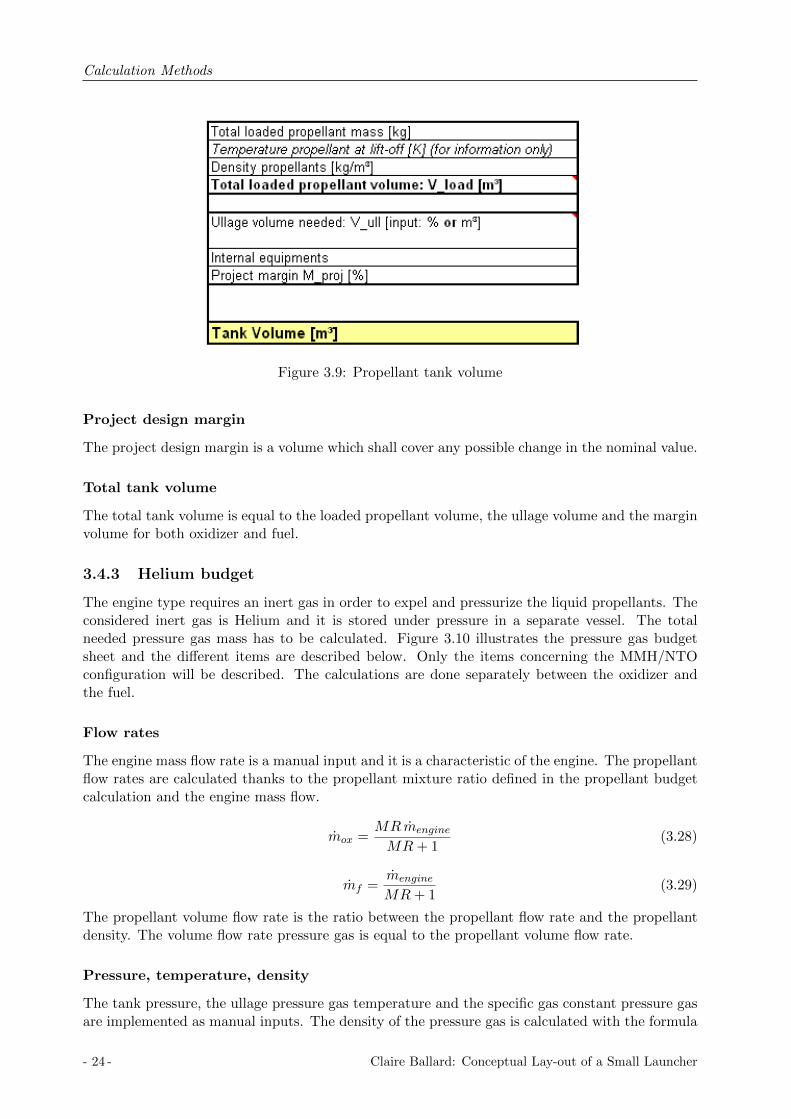
The propellant tank volume can be determined once the propellant budget has been done andonce the total needed propellant mass is known. Figure 3.9 illustrates the propellant tank volumesheet. The volume calculations are done separately between the fuel and the oxidizer.
The manual inputs are the total loaded propellant mass, the density of the propellants, theullage volume and the project design margin. The propellant volume is equal to the propellantmass divided by the propellant density.
Vox,load =mox,load
ρox(3.26)
Vf,load =mf,load
ρf(3.27)
Ullage volume
The ullage volume corresponds to the volume in the tank which is not filled with propellant.
Claire Ballard: Conceptual Lay-out of a Small Launcher - 23 -
Calculation Methods
Figure 3.9: Propellant tank volume
Project design margin
The project design margin is a volume which shall cover any possible change in the nominal value.
Total tank volume
The total tank volume is equal to the loaded propellant volume, the ullage volume and the marginvolume for both oxidizer and fuel.
3.4.3 Helium budget
The engine type requires an inert gas in order to expel and pressurize the liquid propellants. Theconsidered inert gas is Helium and it is stored under pressure in a separate vessel. The totalneeded pressure gas mass has to be calculated. Figure 3.10 illustrates the pressure gas budgetsheet and the different items are described below. Only the items concerning the MMH/NTOconfiguration will be described. The calculations are done separately between the oxidizer andthe fuel.
Flow rates
The engine mass flow rate is a manual input and it is a characteristic of the engine. The propellantflow rates are calculated thanks to the propellant mixture ratio defined in the propellant budgetcalculation and the engine mass flow.
mox =MRmengine
MR+ 1(3.28)
mf =mengine
MR+ 1(3.29)
The propellant volume flow rate is the ratio between the propellant flow rate and the propellantdensity. The volume flow rate pressure gas is equal to the propellant volume flow rate.
Pressure, temperature, density
The tank pressure, the ullage pressure gas temperature and the specific gas constant pressure gasare implemented as manual inputs. The density of the pressure gas is calculated with the formula
- 24 - Claire Ballard: Conceptual Lay-out of a Small Launcher

Calculation Methods
Figure 3.10: Pressure budget
for the ideal gas equation. The calculations is done for both tank, fuel and oxidizer.
ρHe =p
THeR(3.30)
where p propellant pressure [Pa]R specific gas constant [J/molK]THe Helium temperature [K]ρHe Helium density [kg/m3]
Pressure gas need
The pressure gas need is equal to the product between the mass flow rate of the pressure gasand the pressurization duration which is equal to the ratio between the propellant mass for theoperational consumption and the propellant flow rate.
Margins
The project margin is inserted as a manual input.
Total need pressure gas
The total need pressure gas is the sum of the total gas needed and the margins.
Once the helium mass is known, the maximal expected operating pressure (MEOP) has to bedefined. This MEOP is important in the dimensioning of the helium vessels. Figure 3.11 illus-trates the pressure gas compression sheet.
Claire Ballard: Conceptual Lay-out of a Small Launcher - 25 -

Calculation Methods
Figure 3.11: Maximum helium pressure
Maximum He regulated pressure
The value for the maximum helium regulated pressure is dependant on the propellant system andit is implemented as a manual input.
He needed for propellant expulsion only
The helium mass needed is directly calculated from the previous calculations. The helium con-sumption variation is set at 5% in this study. The formula which enables the calculation of thehelium needed for propellant expulsion is written below.
pHe,prop =mHe,tot +mHe,var
MHe 10−3zHeRHe
THeVHe,vessel 10−3
10−5 (3.31)
where MHe helium molar mass [g/mol]zHe helium compressibility factor [−]RHe general gas constant [J.mol]THe helium temperature [K]VHe,vessel helium vessel (manual input) [L]
Margins
Due to the design of the vessel, a pressure residual of helium can not be expelled. From experi-ence the non consumable helium pressure is fixed to 30bars. 10bars are considered for the heliumconsumption deviations, for uncertainty and margin, for the pressure decrease due to temperaturecompensation and for the pressure rise due to temperature compensation. The maximum operat-ing pressure is the sum of the different pressure defined before.
By changing the volume of the helium vessel, the maximum operating pressure can be varied.
3.5 Structural Mass
In order to design the upper-stage, the different parts of the structure have to be defined. Thefollowing part explains the calculations needed to define the upper-stage structure.
- 26 - Claire Ballard: Conceptual Lay-out of a Small Launcher
Calculation Methods
Structures of spacecraft have to be resistant enough to support the load and accelerations, andthey have to be as light as possible. Nowadays, Finite-Element Methods enable analysis of nearlyall the possible structures but the calculations usually takes a long time. For the purpose of thisstudy, the need to get a rough and fast estimation is essential, therefore simplified calculationmethods are used to estimate loads and structural masses.In this section, the Structural Mass Calculation Software Tool is explained. It has been designedby the same student and it is an Microsoft Excel based tool [3]. Unlike the previous tool, someimprovements have been made in the Structural Mass Calculation Software Tool, and so the cal-culations will be explained in the following parts. The changes have been made in order to developin more detail the upper-stage structure.
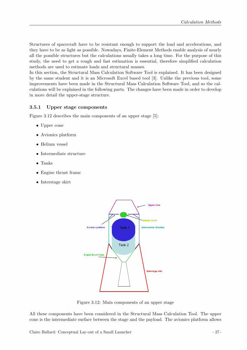
3.5.1 Upper stage components
Figure 3.12 describes the main components of an upper stage [5]:
• Upper cone
• Avionics platform
• Helium vessel
• Intermediate structure
• Tanks
• Engine thrust frame
• Interstage skirt
Figure 3.12: Main components of an upper stage
All these components have been considered in the Structural Mass Calculation Tool. The uppercone is the intermediate surface between the stage and the payload. The avionics platform allows
Claire Ballard: Conceptual Lay-out of a Small Launcher - 27 -

Calculation Methods
a fixture for all the instruments. The helium vessel is fixed to the avionics platform or the enginethrust frame. The intermediate structure has a shape of a cylinder and carries the loads from thestructure above and builds the junction to the interstage structure below. The interstage structurecan have the shape of a cylinder or can be conical depending on the diameter of the stage below.The interstage skirt is the intermediate structure between the upper stage and the stage below.This structure is dropped when the upper stage separates itself from the stage below.
3.5.2 Structural Mass Calculation Software Tool
Illustrations of the complete tool can found in the Appendix D.
The Structural Mass Calculation Tool has been modified in the purpose of this study. Thistool can support three different stage architectures: the common bulkhead tank as load-bearing(on the left of Figure 3.13) or not load-bearing version(in the middle of Figure 3.13) and thespherical-cylindrical tank as not load-bearing version (on the right of Figure 3.13).
Figure 3.13: Tank configurations
The structural masses are evaluated regarding the loads and resulting fluxes and momentsduring the whole mission. As the need is to get a fast estimation of the structure masses, someassumptions have been made and they are listed below:
• all dome tanks are treated as ellipsoidal and the length of the dome is fixed.
• relatively small parts such as skirts, clampband and jettisons for separation systems are notconsidered.
Input Data
This section summarizes the manual inputs for the Structural Mass Calculation Tool.
First of all, the tank configuration has to be chosen by activating check-boxes, the calculationsare done depending on the tank configuration.
AccelerationsThe acceleration factors are important in the dimensioning of a stage and describe the gravita-tional force which affects the stage during its ascent.
- 28 - Claire Ballard: Conceptual Lay-out of a Small Launcher
Calculation Methods
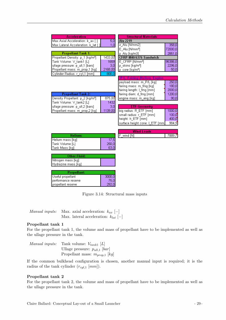
Figure 3.14: Structural mass inputs
Manual inputs: Max. axial acceleration: kax [−]Max. lateral acceleration: klat [−]
Propellant tank 1For the propellant tank 1, the volume and mass of propellant have to be implemented as well asthe ullage pressure in the tank.
Manual inputs: Tank volume: Vtank1 [L]Ullage pressure: pull,1 [bar]Propellant mass: mprop,1 [kg]
If the common bulkhead configuration is chosen, another manual input is required; it is theradius of the tank cylinder (rcyl,1 [mm]).
Propellant tank 2For the propellant tank 2, the volume and mass of propellant have to be implemented as well asthe ullage pressure in the tank.
Claire Ballard: Conceptual Lay-out of a Small Launcher - 29 -

Calculation Methods
Manual inputs: Tank volume: Vtank2 [L]Ullage pressure: pull,2 [bar]Propellant mass: mprop,2 [kg]
Structural MaterialsTwo different structural materials are used in this tool: an aluminum alloy and a composite mate-rial. The aluminum alloy is Aluminum 2219 which is a common material in aerospace design. Thecomposite material is a sandwich structure which consists of carbon fiber skins and a hexagonalaluminum honeycomb as core material.For aluminum 2219, the yield stress, the modulus of elasticity and the material’s density have tobe entered.
Manual inputs: Yield stress: σAlu [N/mm2]Modulus of elasticity: EAlu [N/mm2]Density: ρAlu [kg/m3]
For the composite material, the modulus of elasticity and the density of the CFRP as well asthe density of the honeycomb core material have to be implemented.
Manual inputs: CFRP modulus of elasticity: ECFRP [N/mm2]CFRP density: ρCFRP [kg/m3]Core density: ρcore [kg/m3]
Payload fairing and engineThe fairing is the structure placed on the top of the upper stage which covers the payload duringthe ascent. The payload mass and the fairing mass, length and diameter have to be defined. Theengine mass is required as well.
Manual inputs: Payload mass: mpay [kg]Fairing mass: mfair [kg]Fairing length: lfair [mm]Fairing diameter: dfair [mm]Engine mass: meng [kg]
Engine thrust frameThe engine thrust frame has a conic geometry. The cone characteristics are also required inputs.
Manual inputs: Big radius: RETF [mm]Small radius: rETF [mm]Height: hETF [mm]
Axial fluxesThe stage has to be designed in order to withstand the axial fluxes via the structure. For thecalculation of theses axial fluxes, the stage has been separated into sections. Each section has aconstant load. The sections are represented in Figure 3.15 for each tank configuration. The loadsfor each section are summarized below.
• Section 1: Payload + Fairing + Wind loads
• Section 2: section 1 mass + Propellant mass + Helium storage
• Section 3: section 2 mass + Engine mass
For the calculations concerning the tank structure, in the load-bearing version, the load consideredis the load of section 2, in the non load-bearing version, the only load considered is the mass ofpropellant.
- 30 - Claire Ballard: Conceptual Lay-out of a Small Launcher

Calculation Methods
Figure 3.15: Section level of the evaluated tank configuration
The length and the diameter of each section has to be manually implemented.
Figure 3.16: Structural load
For each section, the axial fluxes are calculated separately as explained below.The axial load is calculated thanks to the section mass and the axial acceleration factor.
Fax = msec kax g (3.32)
The bending torque for each section is calculated by considering the point of action to be situatedin the middle of the section.
Msec,i = (msec,i)lsec,i
2g klat + Fwind
lsec,12
(3.33)
where Fwind Wind loads [N ]g gravitational acceleration [m/s2]klat max. lateral acceleration factor [−]msec,i mass of the section i [kg]lsec,i length of the section i [m]
The axial load per perimeter and the bending moment per area are calculated for each section.
nFax =Faxπ dsec
(3.34)
nM =M
π d2sec4
(3.35)
Finally, the total axial fluxes are the sum of the axial load per perimeter and the bending momentper area.
Claire Ballard: Conceptual Lay-out of a Small Launcher - 31 -

Calculation Methods
Structural mass calculations
The total structural mass of the stage is calculated by the sum of all the components of the stage.For some parts, the calculations have been done by scaling from a known design. This is done inorder to quickly approximate the different parts.
The upper cone structureThe upper cone structure consists of the payload adaptor.The payload adapter is on what thepayload is attached to during the flight. Its mass is scaled from the AVUM payload adapter [25].
The avionics platformThe avionic platform is fixed to the intermediate structure and secures all the avionics equipment.It also supports the Helium and Hydrazine tanks if needed. Its mass is calculated by scaling froma known avionics platform mass.
Tank geometryThe geometry and surfaces of the tank are calculated automatically thanks to the tank volumeand with the input of the cylinder radius for the common bulkhead configuration. No input isrequired for the spherical-cylindrical configuration. The calculations are explained below for thetwo configurations. The tank geometry calculations are done in a separate sheet in the Excel tool.Figure 3.17 illustrates this sheet.
The common bulkhead configurationThe tanks have a cylinder shape and the dome is an ellipsoidal shape. The length of the dome isequal to the radius of the cylinder divided by a fixed coefficient [19].
rdome =rcyl√
2(3.36)
The dome surface is calculated as the half of an ellipsoid surface:
Sdome = π[r2cyl +r2cyl
2 sinαln(1 +
sinα
cosα)] (3.37)
α = arccos1√2
(3.38)
Both cylinder tanks have the radius rcyl defined as a manual input. The cylinder length of tank1 is calculated with the tank volume, the cylinder radius and the dome volume.
hcyl,1 =1
2πrcyl[Vtank,1 −
4
3√
2πr3cyl] (3.39)
The cylinder length of tank 2 is calculated with the volume of the tank 2.
hcyl,2 =Vtank,2πr2cyl
(3.40)
The cylinder surface areas are also calculated thanks to the formulae:
Scyl,1 = 2πrcylhcyl (3.41)
- 32 - Claire Ballard: Conceptual Lay-out of a Small Launcher

Calculation Methods
Figure 3.17: Tank geometry calculations
Spherical-cylindrical configurationThe sphere radius is calculated from the total tank volume.
rsph = (3
4π(Vtank,1 + Vtank,2))
1/3 (3.42)
The cylinder length is calculated thanks to the sphere radius and the tank volume.
hcyl = 2 ∗ [r3sph −3
4π∗ Vtank,1]1/3 (3.43)
From the cylinder length, the dome length is calculated.
rdome = rsph −1
2hcyl (3.44)
The surface areas of the cylinder, the dome and the spherical tank are calculated as shown below.
Sdome = 2π rcyl hdome (3.45)
Scyl = 2π rcyl hcyl (3.46)
Stank,2 = 4π r2sph − 2 ∗ Sdome (3.47)
Tank 1 (The tank parts are all in Aluminum)Common bulkhead configurationThe tank 1 has a cylinder shape with two domes. The total tank mass includes:
Claire Ballard: Conceptual Lay-out of a Small Launcher - 33 -
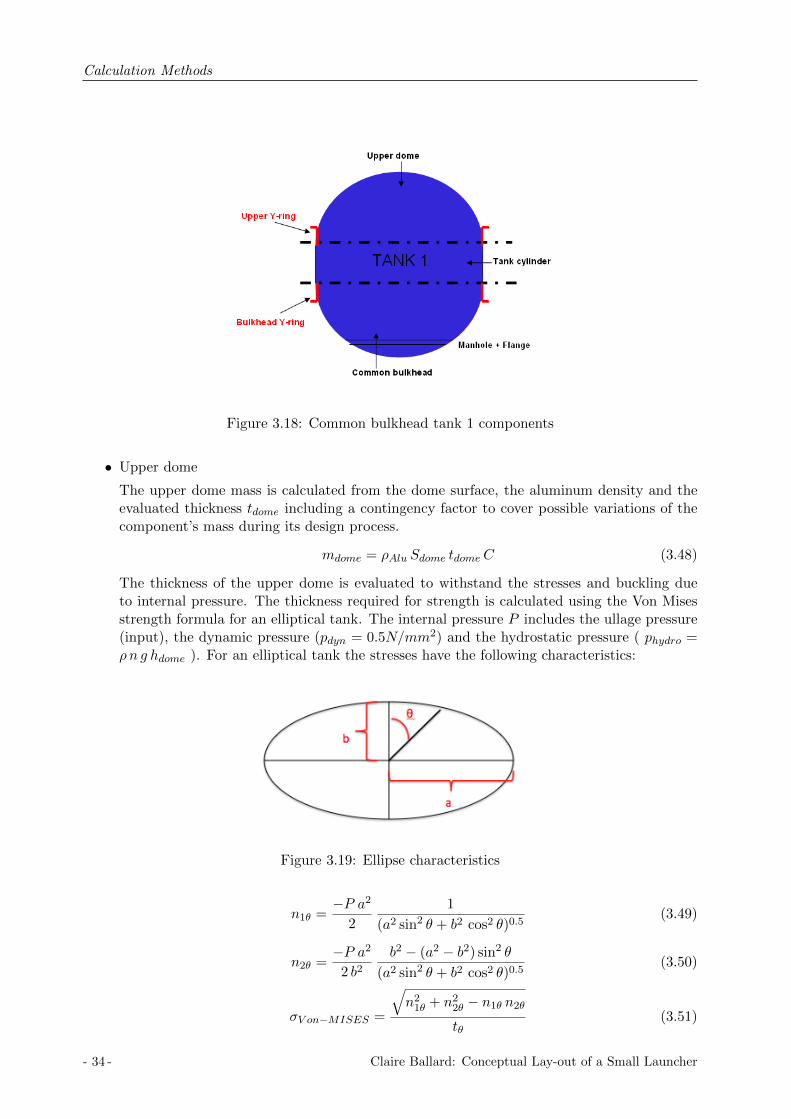
Calculation Methods
Figure 3.18: Common bulkhead tank 1 components
• Upper dome
The upper dome mass is calculated from the dome surface, the aluminum density and theevaluated thickness tdome including a contingency factor to cover possible variations of thecomponent’s mass during its design process.
mdome = ρAlu Sdome tdomeC (3.48)
The thickness of the upper dome is evaluated to withstand the stresses and buckling dueto internal pressure. The thickness required for strength is calculated using the Von Misesstrength formula for an elliptical tank. The internal pressure P includes the ullage pressure(input), the dynamic pressure (pdyn = 0.5N/mm2) and the hydrostatic pressure ( phydro =ρn g hdome ). For an elliptical tank the stresses have the following characteristics:
Figure 3.19: Ellipse characteristics
n1θ =−P a2
2
1
(a2 sin2 θ + b2 cos2 θ)0.5(3.49)
n2θ =−P a2
2 b2b2 − (a2 − b2) sin2 θ
(a2 sin2 θ + b2 cos2 θ)0.5(3.50)
σV on−MISES =
√n21θ + n22θ − n1θ n2θ
tθ(3.51)
- 34 - Claire Ballard: Conceptual Lay-out of a Small Launcher
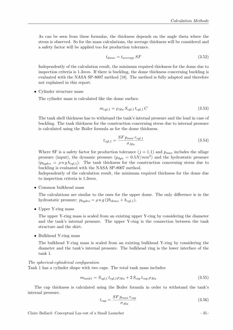
Calculation Methods
As can be seen from these formulas, the thickness depends on the angle theta where thestress is observed. So for the mass calculations, the average thickness will be considered anda safety factor will be applied too for production tolerance.
tdome = taverage SF (3.52)
Independently of the calculation result, the minimum required thickness for the dome due toinspection criteria is 1.3mm. If there is buckling, the dome thickness concerning buckling isevaluated with the NASA SP-8007 method [18]. The method is fully adapted and thereforenot explained in this report.
• Cylinder structure mass
The cylinder mass is calculated like the dome surface.
mcyl,1 = ρAlu Scyl,1 tcyl,1C (3.53)
The tank shell thickness has to withstand the tank’s internal pressure and the load in case ofbuckling. The tank thickness for the construction concerning stress due to internal pressureis calculated using the Boiler formula as for the dome thickness.
tcyl,1 =SF pmax rcyl,1
σAlu(3.54)
Where SF is a safety factor for production tolerance (j = 1.1) and pmax includes the ullagepressure (input), the dynamic pressure (pdyn = 0.5N/mm2) and the hydrostatic pressure(phydro = ρn g hcyl,1). The tank thickness for the construction concerning stress due tobuckling is evaluated with the NASA SP-8007 method.Independently of the calculation result, the minimum required thickness for the dome dueto inspection criteria is 1.3mm.
• Common bulkhead mass
The calculations are similar to the ones for the upper dome. The only difference is in thehydrostatic pressure: phydro = ρn g (2hdome + hcyl,1).
• Upper Y-ring mass
The upper Y-ring mass is scaled from an existing upper Y-ring by considering the diameterand the tank’s internal pressure. The upper Y-ring is the connection between the tankstructure and the skirt.
• Bulkhead Y-ring mass
The bulkhead Y-ring mass is scaled from an existing bulkhead Y-ring by considering thediameter and the tank’s internal pressure. The bulkhead ring is the lower interface of thetank 1.
The spherical-cylindrical configurationTank 1 has a cylinder shape with two caps. The total tank mass includes:
mtank1 = Scyl,1 tcyl,1ρAlu + 2Scap tcap ρAlu (3.55)
The cap thickness is calculated using the Boiler formula in order to withstand the tank’sinternal pressure.
tcap =SF pmax rcap
σAlu(3.56)
Claire Ballard: Conceptual Lay-out of a Small Launcher - 35 -

Calculation Methods
Figure 3.20: Spherical-Cylindrical tank 1 components
Where SF is a safety factor for production tolerance (j = 1.1) and pmax includes the ullagepressure (input), the dynamic pressure (pdyn = 0.5N/mm2) and the hydrostatic pressure (phydro =ρn g hcap).Independently of the calculation result, the minimum required thickness for the dome due toinspection criteria is 1.3mm. The cylinder tank thickness has to be dimensioned for bearing thetank’s internal pressure as well as buckling, as the cylinder is placed inside the sphere with apressure difference. The formula used to calculate the thickness is:
tcyl,1 = (pull
1.5 0.6 0.91rcyl,1hcyl,1
EAlu)0.8 rcyl,1 (3.57)
Tank 2 (The tank parts are all in Aluminum)Common bulkhead configurationTank 2 has a cylinder shape with two domes. The total tank mass includes:
• Tank cylinder
The cylinder mass is calculated from the cylinder surface area and the cylinder thickness.
mcyl,2 = ρAlu Scyl,2 tcyl,2C (3.58)
The tank shell thickness has to withstand the tank’s internal pressure as well as bucklingloads. The tank thickness for the construction concerning stress due to internal pressure iscalculated using the Boiler formula.
tcyl,2 =SF pmax rcyl,2
σAlu(3.59)
Where SF is a safety factor for production tolerance (j = 1.1) and pmax includes the ullagepressure (input), the dynamic pressure (pdyn = 0.5N/mm2) and the hydrostatic pressure
- 36 - Claire Ballard: Conceptual Lay-out of a Small Launcher

Calculation Methods
Figure 3.21: Common bulkhead tank 2 components
(phydro = ρn g hcyl,2). The tank thickness for the construction concerning stress due tobuckling is evaluated with the NASA SP-8007 method.Again, the minimum required dome thickness is 1.3mm.
• Lower dome
The lower dome mass is calculated from the dome surface area, the aluminum density andthe evaluated thickness tdome.
mdome = ρAlu Sdome tdomeC (3.60)
The thickness of the lower dome is calculated as the two previous domes. The only differenceis in the hydrostatic pressure: phydro = ρn g hcyl,2.
• Lower ring
The lower Y-ring mass is scaled from an existing lower Y-ring by considering the diameterand the tank’s internal pressure. The lower Y-ring is the connection between the tankstructure and the skirt.
Spherical-cylindrical configurationThe mass of the spherical tank is calculated using the Aluminum’s density, the spherical surfacearea and the spherical tank thickness.
msph = ρAlu Ssph tsphC (3.61)
The shell thickness of the the spherical tank for the construction concerning stress due tointernal pressure is calculated using the Boiler formula.
tsph =SF pmax rsph
2σAlu(3.62)
Where SF is a safety factor for production tolerance (j = 1.1) and pmax includes the ullage pres-sure (input), the dynamic pressure (pdyn = 0.5N/mm2) and the hydrostatic pressure (phydro =ρn g 2rsph).Again, the minimum required dome thickness is 1.3mm.
The intermediate structure (using composite material)The intermediate structure includes:
Claire Ballard: Conceptual Lay-out of a Small Launcher - 37 -
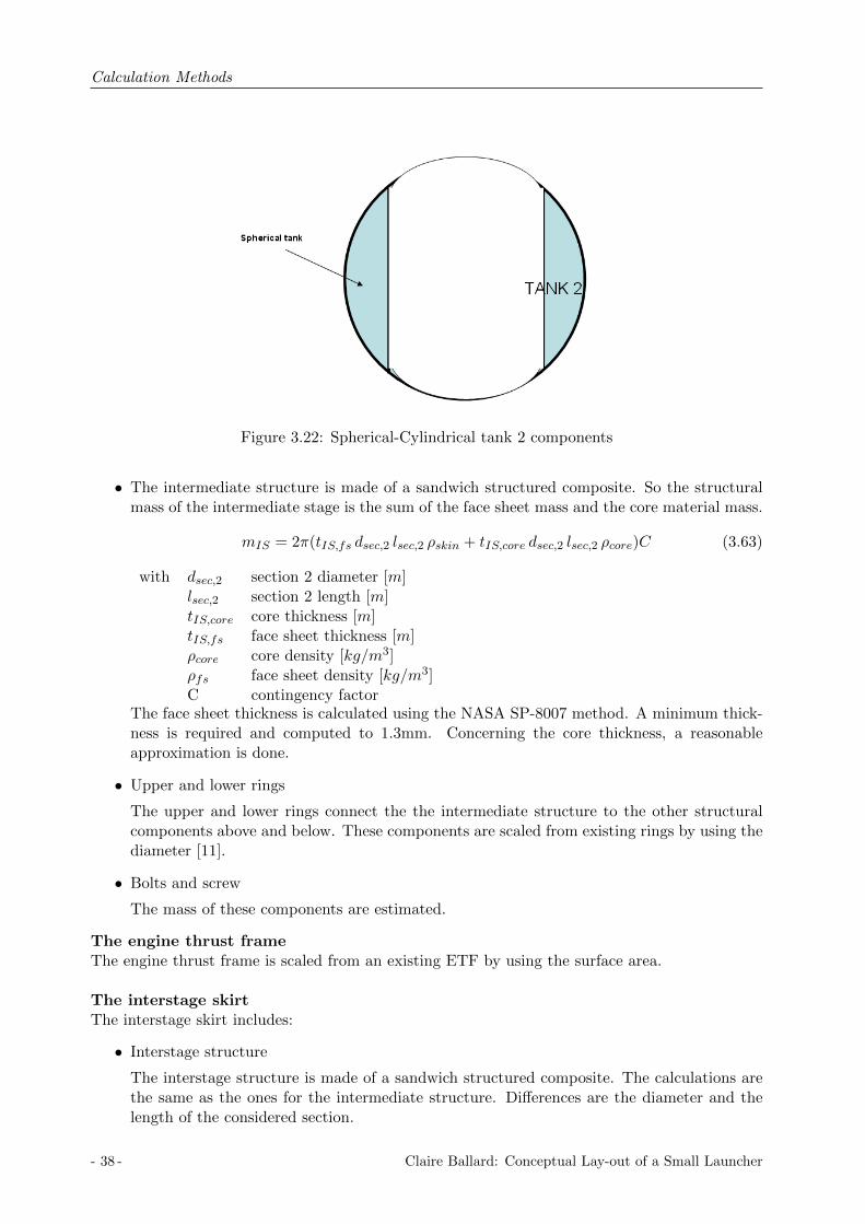
Calculation Methods
Figure 3.22: Spherical-Cylindrical tank 2 components
• The intermediate structure is made of a sandwich structured composite. So the structuralmass of the intermediate stage is the sum of the face sheet mass and the core material mass.
mIS = 2π(tIS,fs dsec,2 lsec,2 ρskin + tIS,core dsec,2 lsec,2 ρcore)C (3.63)
with dsec,2 section 2 diameter [m]lsec,2 section 2 length [m]tIS,core core thickness [m]tIS,fs face sheet thickness [m]ρcore core density [kg/m3]ρfs face sheet density [kg/m3]C contingency factor
The face sheet thickness is calculated using the NASA SP-8007 method. A minimum thick-ness is required and computed to 1.3mm. Concerning the core thickness, a reasonableapproximation is done.
• Upper and lower rings
The upper and lower rings connect the the intermediate structure to the other structuralcomponents above and below. These components are scaled from existing rings by using thediameter [11].
• Bolts and screw
The mass of these components are estimated.
The engine thrust frameThe engine thrust frame is scaled from an existing ETF by using the surface area.
The interstage skirtThe interstage skirt includes:
• Interstage structure
The interstage structure is made of a sandwich structured composite. The calculations arethe same as the ones for the intermediate structure. Differences are the diameter and thelength of the considered section.
- 38 - Claire Ballard: Conceptual Lay-out of a Small Launcher

Calculation Methods
• Upper and lower rings
The upper and lower rings connect the intermediate structure to the other structural com-ponents above and below. These components are scaled from existing rings by using thediameter.
• Bolts and screw
The mass of these components are estimated.
• Rivets
The rivets are scaled from existing rings by using the diameter.
Claire Ballard: Conceptual Lay-out of a Small Launcher - 39 -

Calculation Methods
- 40 - Claire Ballard: Conceptual Lay-out of a Small Launcher

Code Explanation
Chapter 4
Code Explanation
As explained previously, the launcher performances need to be evaluated, therefore a code hasbeen written using the MATLAB software. By setting the launcher characteristics and the timewhen the gravity turn is applied, the MATLAB code enables calculations and representation ofthe rocket trajectory as well as the elliptical orbit characteristics that the launcher reaches. Thischapter explains the written code.
The code has been changed and improved during the 6 months of this master thesis. The mainchanges have been done on the gravity turn program. There are actually two code versions de-pending on the gravity turn program: one where the rate of the gravity turn program is a constantand one where this rate depends on the other variables and so is a function of time. This chapterexplains the code version with a non constant gravity turn which is the latest version of the code.A user’s manual has been written and can be found in references [26].
The MATLAB code consists of three different folders: the VEGA folder, the ARIANE 5 folderand the SmallLauncher folder. In each of those folders, there are again two folders: one for a basicsimulation and one for an optimization simulation. There are three major folders because theVEGA launcher and the ARIANE 5 launcher have specific properties that a small launcher doesnot have. For instance, the VEGA launcher has got four stages compared to the small launcherwhich shall be designed with two or three stages. Furthermore, the ARIANE 5 launcher has gottwo boosters which burn simultaneously then the second stage. In contrast, the small launcherburns its stages one after one. But it is important to notice that these folders are based on thesame code, there are just minor modifications in the VEGA and ARIANE 5 folders in order totake into account the specific properties.The following code explanations will focus on the SmallLauncher folder.
4.1 The Simulation Folder
The two important files in the simulation folder are the Main file and the RocketData file. Theother files are functions. The RocketData file describes the rocket data and important constants,so it contains all the inputs except the inputs concerning the gravity turn program:
• Number of boosters N
• Specific impulsion of each stage(Isp1 Isp2 Isp3
)[s]
• Propellant mass of each stage(mp1 mp2 mp3
)[kg]
• Structural mass of each stage(ms1 ms2 ms3
)[kg]
Claire Ballard: Conceptual Lay-out of a Small Launcher - 41 -

Code Explanation
Figure 4.1: Rocketdata file
• Thrust of each stage(T1 T2 T3
)[N ]
• Mass flow rate of each stage m = TIsp g0
[kg/s]
• Burn time of each stage tb = mpm [s]
• Required propellant to perform the circularization mp,circ
• Fairing mass [kg]
• Fairing dropped time [s]
• Drag coefficient [−]
• Lateral surface of each stages [m2]
• Earth radius Re [m]
• Desired orbit inclination [rad]
• Initial velocity V0 = 2π Re24∗3600 sin(inc) [m/s]
In Figure 4.1, the RocketData file is represented.
The functions files are:
- 42 - Claire Ballard: Conceptual Lay-out of a Small Launcher

Code Explanation
area The area function returns the lateral area of the rocket depending on the time.
dens The dens function returns the local density depending on the altitude of the rocket.
gravity The gravity function returns the local gravity depending on the altitude of the rocket.
zval The zval function forces the zero value.
Thr The Thr function returns the thrust of the rocket depending on the time.
mass The mass function returns the mass of the rocket depending on the time.
rock1 The rock1 function consists of the system of equations of motion before and after the pitchprogram.
rock2 The rock2 function consists of the system of equations of motion during the pitch program.
stop The stop function enables to get the time when the circularization needs to be done, i.e.when the satellite reaches the apogee of the elliptical orbit.
All the function files screen shots are in Annex C.
The simulation steps are summarized in Figure 4.2. In the Main file is the code to run a simula-tion and to plot different variables as a function of time. There are two parameters which can bechanged in the Main file and those parameters correspond to the pitch program. It is possible tochange the time when the pitch program is applied.
First the Main file runs. It saves and loads all the variables from the RocketData file, thena code has been written in order to solve numerically the system of differential equations, thenumerical solver used is the MATLAB solver ode45. This solver is a numerical solver based on anexplicit Runge-Kutta (4,5) formula. It is a one step solver, that means it only needs the solution atthe immediately preceding time point y(tn−1) in order to compute y(tn). It solves a systems of nonlinear differential equations y = f(t, y). In this simulation the state vector is y =
(V γ X H
).
The basic simulation is divided in three parts. The first part of the simulation is from 0 sec-onds to the beginning of the pitch program, the solver resolves the equations written in the rock1function. The equations taken into account are the equations 3.4, 3.5, 3.6 and 3.7. The rockettrajectory is a vertical ascension. The flight path angle stays constant during this interval.
The second part is from the beginning of the pitch program to the end of the pitch program,the solver resolves the equations written in the rock2 function. The equations taken into accountare the equations 3.4, 3.5 and 3.6. In order to apply the pitch program a term is added in theequation 3.7.
V γ = −g cos(γ) +V 2
RE +Hcos(γ)− γ0 (4.1)
The additional term is γ0 and it represents the rate of decrease of the flight path angle. This rateis a function of the other variables and so it is a function of time as well.
The last part is from the end of the pitch program to the end of the added time burning ofeach stage, the solver resolves the equations written in the rock1 function. At the end of thesimulation, a code is used in order to calculate which orbit the rocket has reached, so the perigeeand the apogee are calculated as explained previously. At the end of the simulation, the rockethas reached the transfer elliptical orbit (point A on Figure 4.3).
Then there is also a possibility to perform the circularization of the orbit. The purpose of thesmall launcher is to put the satellite in a circular orbit with a radius of 700 km. In order to dothat, the launcher first reaches an elliptical orbit and then there is a re-ignition of the last stageto circularize the orbit. But first, it is primordial to know at what moment the circularization
Claire Ballard: Conceptual Lay-out of a Small Launcher - 43 -

Code Explanation
Figure 4.2: Matlab code explanation
has to be done. In order to find the time when the spacecraft reaches the apogee of the orbit asimulation is run from the end of the previous simulation to a certain time. This time has to bebig enough in order to be sure that during the considered interval the spacecraft passes the apogeeof the orbit. The solver is used with an option in order to know at what time the launcher reachesthe apogee. The option uses the stop function. It is important to notice that during this phase,the launcher is in orbit so the thrust is equal to zero and the mass does not change. There is noneed to change anything, the mass and thrust function are defined to handle the situation whenthe launcher is in orbit and when it has to be re-ignited as well. Once the time when the upperstage reaches the apogee is known, tcirc, the previous simulation is run again but this time untiltcirc. Then another simulation is run from tcirc to tcirc + 500 in order to see the circularization.It is important to notice that the propellant needed for the re-ignition is considered in the codeas part of the payload until it is used to perform the circularization.
In the Matlab workspace, all the variables can be seen. Some plots are already implementedto be shown at the end of the simulation.
- 44 - Claire Ballard: Conceptual Lay-out of a Small Launcher

Code Explanation
Figure 4.3: Rocket trajectory
4.2 The Optimization Folder
The rocket trajectory simulation in the optimization folder is done as explained previously. Theonly changes are most of the variables are defined as global variables in the main file in orderto be changed whilst the optimization program is running. The Optimization folder contains thesame functions as defined in the simulation folder. There is a main file in order to run a normalsimulation and some optimization files depending on what variables can be changed.
The variables defined as global variables are:
• Specific impulsion of each stage(Isp1 Isp2 Isp3
)[s]
• Propellant mass of each stage(mp1 mp2 mp3
)[kg]
• Structural mass of each stage(ms1 ms2 ms3
)[kg]
• Thrust of each stage(T1 T2 T3
)[N ]
• Mass flow rate of each stage m = TIsp g0
[kg/s]
• Burn time of each stage tb = mpm [s]
• Fairing dropped time [s]
• Payload mass [kg]
There are several optimization files depending on what variables can be changed. The purposeof the optimization is always to reach a desired orbit. The optimization program is always atleast done on the pitch program, but it is also possible to add others parameters, namely thepayload mass and the propellant mass in the stages. The following description will describe theoptimization file which optimizes the trajectory by changing gravity turn parameters. The otheroptimization files can be easily understood from this file.
Gravity turn optimization
First, the rocket data has to be defined at the beginning of the file. Then the vertices need tobe defined. The vertices coordinates are the variables which will be changed in order to minimizethe objective function. The vertices coordinates are:
• tg(1): beginning of the pitch program
Claire Ballard: Conceptual Lay-out of a Small Launcher - 45 -

Code Explanation
• tg(2): end of the pitch program
The objective function is
F = (ra,calculated − ra,desired)2 + (rp,calculated − rp,desired)2 (4.2)
where: ra,calculated calculated apogee radius [m]ra,desired desired apogee radius [m]rp,calculated calculated perigee radius [m]rp,desired desired perigee radius [m]
As a vertex has two coordinates, three vertices are needed to do the optimization. They aredefined as follows:
• v1=(tg1 tg2
)• v2=
(tg1 + ε1 tg2
)• v3=
(tg1 tg2 + ε2
)So three simulations are run and respectively the three vertices and objective functions are cal-culated in the three cases. Then the coordinates of each vertices are changed in regards to thealgorithm explained in the third chapter (Nelder-Mead algorithm). This is done a maximum of200 times, and every 50 loops the optimization is stopped in order to control the convergence.If it seems there is no convergence, it is so possible to stop the optimization. This control isessentially done in order not to waste time as 200 loops take a substantial amount of time, around10 minutes. The optimization stops by itself when the objective function is smaller than 0.01.The optimization loop is schematized in the figure 4.4.
Figure 4.4: Optimization loop description
- 46 - Claire Ballard: Conceptual Lay-out of a Small Launcher

Code Validation
Chapter 5
Code Validation
The written code in Matlab has been validated by using the VEGA launcher and the Ariane 5launcher. As said before, the code has been improved during the 6 months of this master thesis,and the main changes are on the rate of the gravity turn program. At first, the program useda constant gravity turn and it has been validated with the VEGA and Ariane 5 launchers. Theresults are presented in this chapter. Then, with the non constant gravity turn rate, the validationhas been done once again using the VEGA launcher. These results are discussed with the constantgravity turn rate results in this chapter as well.
5.1 VEGA launcher simulation
A simulation with the VEGA launcher has been done in order to validate the code written inMATLAB. The goal of this simulation was to put 1500kg of payload in a circular orbit with aradius of 700km, by first reaching the transfer elliptical orbit with a perigee of 200 km and anapogee of 700 km. The characteristics of the VEGA launcher are shown in Table 5.1, namely thepropellant mass, the dry mass, the specific impulse, the thrust, the burning time and the referencearea of the different stages [9].
The thrust profile of the three first stages have been implemented in the code, they are repre-sented in the Appendix A [14]. In order to reach a circular orbit of 700 km, the VEGA launcherfirst reaches the elliptical orbit with a perigee of 200 km and an apogee of 700 km by burningthe first three stages and a part of the fourth stage, then a circularization is done by burning thepropellant left in the fourth stage. In the written code, the payload takes into account the realpayload plus the needed propellant to circularize the orbit. Table 5.1 shows the characteristics ofthe fourth stage, namely the propellant mass and the burning time needed to reach the ellipticalorbit. In order to circularize the orbit, 100 kg of propellant is needed. The results have been
Entity Stage 1 Stage 2 Stage 3 Stage 4
Engine P80 Z23 Z9 AVUMPropellant Mass [kg] 87,732 23,823 9,935 450Dry Mass [kg] 8,624 2,666 1,397 661Isp [s] 280 289 295 315.5Thrust [kN ] 2261 1196 225 2.45tb [s] 106.4 79.9 101.9 568.3Reference Area [m2] 7.07 7.069Cp [-] 0.310404 0.300009
Table 5.1: Vega launcher characteristics
Claire Ballard: Conceptual Lay-out of a Small Launcher - 47 -

Code Validation
compared to the results from a DLR study [10].
5.2 VEGA launcher simulation results
A simulation has been done with the VEGA launcher in order to validate the MATLAB code. Byusing the optimization program, the best compromise between the payload, the trajectory andthe launcher characteristics have been found. These results have been compared to the ones froma DLR study.
First, the optimization has been done on the gravity turn program, so by changing t1, t2 andthe rate; and the results have been compared with the ones from the DLR study. From thisoptimization the VEGA launcher could reach an elliptical orbit with an apogee of 700km and aperigee of 118km with a payload of 1375kg. The stage characteristics used for this optimizationare the ones used in the DLR study in order to be comparable. From the DLR study, the VEGAlauncher could reach an elliptical orbit with an apogee of 700km and a perigee of 200 km with apayload of 1518kg.
The different variables, namely the speed, the flight path angle and the altitude, have beencompared with the results form the DLR study, and it has been noticed that the results weresignificantly different from the second stage. For instance, as can be seen in Table 5.2, from thesecond stage there was a difference on the altitude of the launcher. In Table 5.2, the altitude,the speed and the flight path angle are written for the end of the three first stages. The resultsfrom this first optimization are listed in Table 5.2 at the line Optimization1. After this firstoptimization the VEGA reaches an elliptical orbit with a perigee of 135km and an apogee of700km, and has a payload of 1371kg. The DLR study shows the VEGA reaches the elliptical orbitwith a perigee of 200 km and an apogee of 700km with a payload of 1518kg.
Stage 1 Stage 2 Stage 3
H V γ H V γ H V γ[km] [km/s] [deg] [km] [km/s] [deg] [km] [km/s] [deg]
DLR study 44 1.9 25 110 4.1 10 162 7.5 3
Optimization 1 44 1.89 20 90 4.1 6.3 120 7.4 1.2
Optimization 2 46 1.9 20 97 4.1 7.5 134 7.4 2.3
Table 5.2: Results comparison with the DLR study
Another optimization has been carried out by changing the variables of the gravity turn andthe amount of propellant in the second and third stage as well. The results from this optimizationare listed in Table 5.2 at the line Optimization2. After this second optimization the VEGAlauncher reaches the elliptical orbit with a perigee of 200 km and an apogee of 700 km, and hasa payload of 1371kg.
Stage 2 Stage 3
mp ms mtot mp ms mtot
[kg] [kg] [kg] [kg] [kg] [kg]
DLR study 23,823.4 2,666.2 26,489.6 9,935.3 1,397.4 11,332.7
Simulation 23,291 2,666.2 25,957.2 9,335 1,397.4 10,732.4
Table 5.3: Stage 2 and 3 in comparison with the DLR study
The characteristics of the second and third stage have been compared with those from the DLRin Table 5.3. The propellant difference in the second stage is around 2% and in the third stage
- 48 - Claire Ballard: Conceptual Lay-out of a Small Launcher

Code Validation
Figure 5.1: Vega launcher simulation from 0km to the elliptical orbit
it is around 6%. For the total amount of propellant, the difference is less than 1%. Compared tothe real performance of the VEGA launcher, there is less than 10% of difference with the resultsfrom the simulation, so the mission is considered as validated.
The following figures show different variables depending on the time during the simulation. InFigure 5.1, the simulation results are shown from the launch pad to the elliptical orbit.
On Figure 5.2, the curves in red represent the trajectory of the fourth stage with the payloadin orbit and thrust equal to zero. The curves in green represent the circularization.
On Figure 5.3, the spacecraft mass, the thrust, the dynamic pressure and the lateral andlongitudinal velocity are represented as a function of time. Concerning the velocity curves, theblue curve is the longitudinal velocity and the red curve is the lateral velocity.
5.3 Ariane 5 launcher simulation
Another simulation has been done with the Ariane 5 launcher in order to validate the code. Thegoal of this simulation was to do a real mission executed by Ariane 5. The chosen mission is themission realized by Ariane 5 on the 13th of October 2006. The specificity of Ariane 5 is that 2solid boosters burn meanwhile the cryogenic stage burns. The drop of these two solid boostersis achieved around 130 seconds after the lift-off, and these two boosters fall down in the ocean.The real trajectory of the Ariane 5 launcher is not actually optimized in order to drop those twoboosters in the ocean and not on a living area. In this simulation, the trajectory optimization hasbeen done and so the results may be different from the reality.
The goal is to put 9031 kg of payload in an elliptical orbit with a perigee of 250 km, an apogeeof 35942 km and an inclination of 7 degrees. Considered in the payload is the mass of the satel-lite and some equipment, namely the cone and the Syldas. The characteristics of the Ariane 5launchers are summarized in Table 5.4 [8]. In this table are the propellant mass, the dry mass, the
Claire Ballard: Conceptual Lay-out of a Small Launcher - 49 -
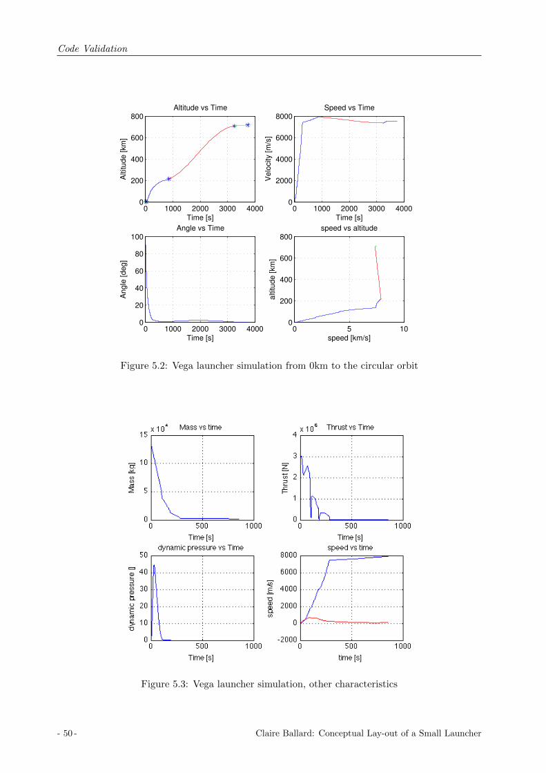
Code Validation
0 1000 2000 3000 40000
200
400
600
800Altitude vs Time
Time [s]
Altitude [km
]
0 1000 2000 3000 40000
2000
4000
6000
8000Speed vs Time
Time [s]
Velo
city [m
/s]
0 1000 2000 3000 40000
20
40
60
80
100Angle vs Time
Time [s]
Angle
[deg]
0 5 100
200
400
600
800speed vs altitude
speed [km/s]
altitude [km
]
Figure 5.2: Vega launcher simulation from 0km to the circular orbit
Figure 5.3: Vega launcher simulation, other characteristics
- 50 - Claire Ballard: Conceptual Lay-out of a Small Launcher

Code Validation
thrust, the specific impulse, the burning time and the reference area of the boosters and stages.In the Matlab code, the characteristics of the second stage are not the same in the function ofthe boosters are burning or have been dropped. While the two solid boosters are burning, thecryogenic stage characteristics are the one at sea level, after the boosters have been dropped, thecryogenic stage characteristics are the ones in the vacuum. This choice has been done in order tohave a more realistic simulation.
Entity Stage 1 Stage 2 Stage 3
Engine EAP EPC ESC-APropellant mass [kg] 480,000 170,000 14,900Dry mass [kg] 80,000 14,700 4,540Thrust [kN ] 14,000 960 (SL) 1390 (vac) 67Isp [s] 274.5 310 (SL) 432 (vac) 446tb [s] 129 537 972Reference Area [m2] 14.61 22.90Cp [-] 0.3 0.3
Table 5.4: Ariane 5 launcher characteristics
The thrust profile of the two solid boosters have been implemented in the code (cf. Annex B).The optimization has only been done on the gravity turn program (t1, t2, rate) as there was nospecial difficulties to reach the desired orbit with the desired payload.
5.4 Ariane 5 launcher simulation results
The optimization has only been done on the gravity turn program. At the end of the optimiza-tion, the Ariane 5 launcher could reach the elliptical orbit with a perigee of 250km and an apogeeof 35942km with a payload of 9670kg. There is less than 10% of difference between the resultsfrom the simulation and the results from the real mission, so the mission is considered as validated.
Represented in figure 5.4 is the spacecraft velocity, the flight path angle and the altitude as afunction of time. The fourth curve corresponds to the altitude as a function of velocity. Repre-sented in Figure 5.5 is the mass, the thrust, the dynamic pressure and the velocities as functionsof time. On the last curve, the blue curve corresponds to the longitudinal velocity whereas thered curve correspond to the lateral velocity.
In the following table, are the spacecraft speed, flight path angle and altitude at the burn out ofthe different stages.
Entity Boosters Stage 1 Upper stage
Time [s] 129 522 1495Velocity [km/s] 2.17 7.02 9.97γ [deg] 42.39 -1.14 9.74Altitude [km] 125 389 509
Table 5.5: Ariane 5 trajectory characteristics at stage burn-out
Claire Ballard: Conceptual Lay-out of a Small Launcher - 51 -

Code Validation
0 500 1000 15000
200
400
600Altitude vs Time
Time [s]
Altitude [km
]
0 500 1000 15000
2000
4000
6000
8000
10000Speed vs Time
Time [s]
Velo
city [m
/s]
0 500 1000 1500−50
0
50
100Angle vs Time
Time [s]
Angle
[deg]
0 5 100
200
400
600speed vs altitude
speed [km/s]
altitude [km
]
Figure 5.4: Ariane 5 launcher simulation from 0km to the elliptical orbit
0 500 1000 15000
2
4
6
8x 10
5 Mass vs time
Time [s]
Mass [kg]
0 500 1000 15000
5
10
15x 10
6 Thrust vs Time
Time [s]
Thru
st [N
]
0 500 1000 15000
50
100
150dynamic pressure vs Time
Time [s]
dynam
ic p
ressure
[]
0 500 1000 1500−5000
0
5000
10000speed vs time
time [s]
speed [m
/s]
Figure 5.5: Ariane 5 launcher simulation, other characteristics
- 52 - Claire Ballard: Conceptual Lay-out of a Small Launcher
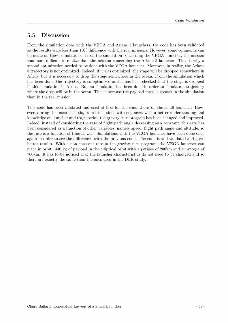
Code Validation
5.5 Discussion
From the simulation done with the VEGA and Ariane 5 launchers, the code has been validatedas the results were less than 10% difference with the real missions. However, some comments canbe made on these simulations. First, the simulation concerning the VEGA launcher, the missionwas more difficult to realize than the mission concerning the Ariane 5 launcher. That is why asecond optimization needed to be done with the VEGA launcher. Moreover, in reality, the Ariane5 trajectory is not optimized. Indeed, if it was optimized, the stage will be dropped somewhere inAfrica, but it is necessary to drop the stage somewhere in the ocean. From the simulation whichhas been done, the trajectory is so optimized and it has been checked that the stage is droppedin this simulation in Africa. But no simulation has been done in order to simulate a trajectorywhere the drop will be in the ocean. This is because the payload mass is greater in the simulationthan in the real mission.
This code has been validated and used at first for the simulations on the small launcher. How-ever, during this master thesis, from discussions with engineers with a better understanding andknowledge on launcher and trajectories, the gravity turn program has been changed and improved.Indeed, instead of considering the rate of flight path angle decreasing as a constant, this rate hasbeen considered as a function of other variables, namely speed, flight path angle and altitude; sothe rate is a function of time as well. Simulations with the VEGA launcher have been done onceagain in order to see the differences with the previous code. The code is still validated and givesbetter results. With a non constant rate in the gravity turn program, the VEGA launcher canplace in orbit 1440 kg of payload in the elliptical orbit with a perigee of 200km and an apogee of700km. It has to be noticed that the launcher characteristics do not need to be changed and sothere are exactly the same than the ones used in the DLR study.
Claire Ballard: Conceptual Lay-out of a Small Launcher - 53 -

Code Validation
- 54 - Claire Ballard: Conceptual Lay-out of a Small Launcher

Results
Chapter 6
Results
The objective of this diploma thesis is to develop a conceptual lay-out of a small launcher. Themethod, described in the previous chapters, is used to analyze the small launcher characteristics.The MATLAB tool is used to simulate the trajectory and to optimize the launcher staging. Theupper stage is designed thanks to an existing Excel tool as explained previously. Several optimumsmall launchers have been designed, the results are summarized and discussed in the followingchapters.Thereafter the most appropriated small launcher is selected, the upper stage is described in moredetail.
6.1 Existing Stages
A requirement for the mission is to use existing stages, research has been done to investigate theactual stages. Solid and liquid stages have been taken into account.
6.1.1 Solid stages
Existing solid boosters have been investigated and more precisely the study has been focused onsmall boosters. As the purpose of the mission is to developed a small launcher, there was noneed to focus on high thrust boosters. The following table summarizes the characteristics of theinvestigated solid boosters, namely the specific impulse, the thrust, the propellant mass, the drymass, and the structural index. From this table, it can be seen than mostly the Brazilian andItalian stages are investigated [2].
S-31 S-40 S-43TM S-40 S-50 PSLV-3 Zefiro 23 Zefiro 9Brazil Brazil Brazil Brazil Brazil India Italy Italy
Isp [s] 260 275 277 260 280 294 289 295Thrust [kN ] 240 208 320 303 517 329 1196 225mp [kg] 616 4452 7184 7222 11000 7300 23906 10115mdry [kg] 284 1212 1536 1328 1493 1100 1845 833SI [−] 0.32 0.21 0.18 0.16 0.12 0.13 0.07 0.08
Table 6.1: Solid boosters characteristics
From the solid stage data, the optimum curves have been defined as explained previously. InFigure 6.1, theses optimum curves are represented, so the thrust, the specific impulse and thestructural index as a function of the propellant mass. The equations which represent the optimumcurves are written as well. Those equations have been implemented in the MATLAB code in orderto find the optimum launchers.
Claire Ballard: Conceptual Lay-out of a Small Launcher - 55 -
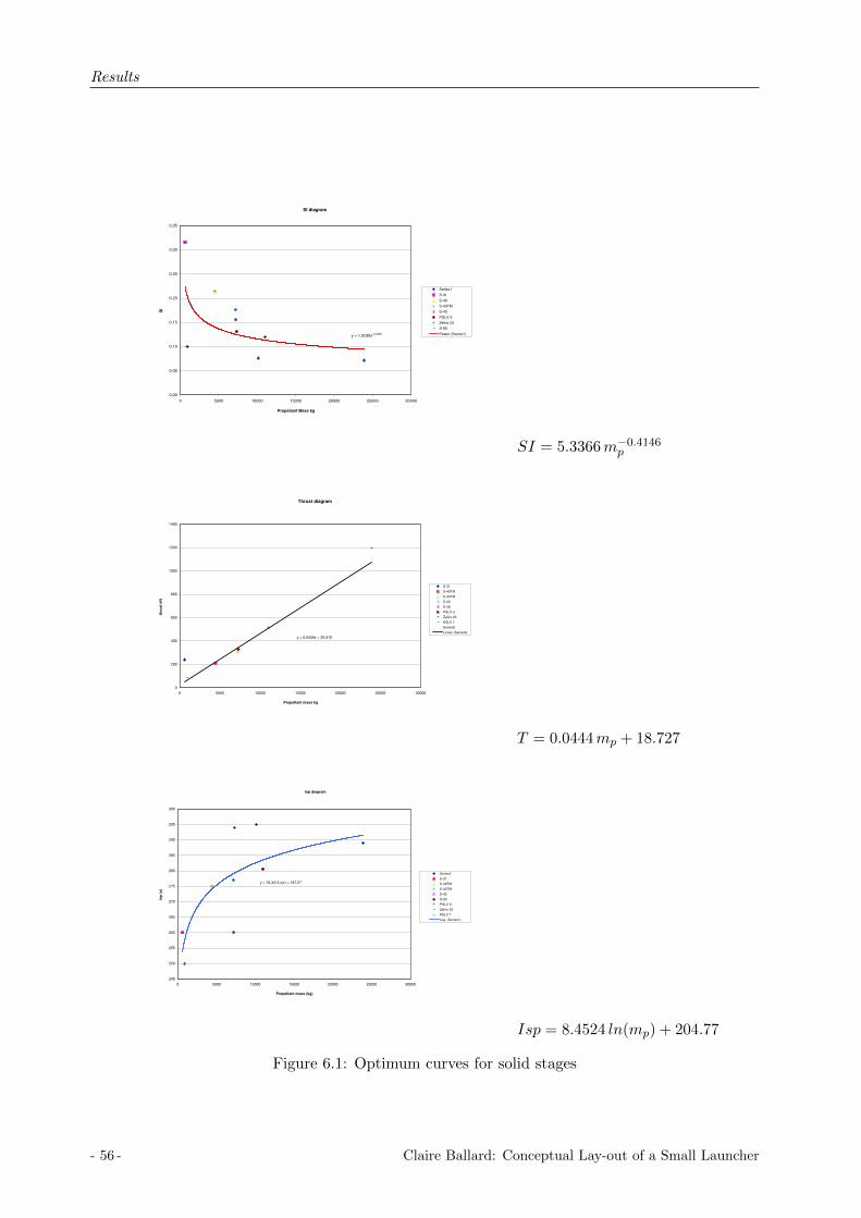
Results
SI diagram
y = 1,0238x-0,2364
0,00
0,05
0,10
0,15
0,20
0,25
0,30
0,35
0 5000 10000 15000 20000 25000 30000
Propellant Mass kg
SI
Series1
S-31
S-40
S-43TM
S-43
PSLV-3
Zefiro 23
S-50
Power (Series1)
SI = 5.3366m−0.4146p
Thrust diagram
y = 0,0439x + 25,915
0
200
400
600
800
1000
1200
1400
0 5000 10000 15000 20000 25000 30000
Propellant mass kg
thru
st
kN
S-31
S-40TM
S-43TM
S-43
S-50
PSLV-3
Zefiro 23
KSLV 1
Series9
Linear (Series9)
T = 0.0444mp + 18.727
Isp diagram
y = 10,341Ln(x) + 187,27
245
250
255
260
265
270
275
280
285
290
295
300
0 5000 10000 15000 20000 25000 30000
Propellant mass (kg)
Isp
(s)
Series1
S-31
S-40TM
S-43TM
S-43
S-50
PSLV-3
Zefiro 23
KSLV 1
Log. (Series1)
Isp = 8.4524 ln(mp) + 204.77
Figure 6.1: Optimum curves for solid stages
- 56 - Claire Ballard: Conceptual Lay-out of a Small Launcher

Results
2.4007m−0.3146p
1.5873T − 130.69
Figure 6.2: Optimum structural index curve and engine mass for liquid stage
6.1.2 Liquid stage
The same investigation, as previous, has been done for the liquid stages, also focusing on smallthrust engines. The results of this study are shown in Table 6.2 [2].
Angara Proton Zenit Zenit Soyuz Soyuz Soyuz KSLV Istage 2 stage2 stage 2 booster booster stage 1 stage 1 U stage 1
Isp [s] 359 326 349 330 310 315 311 338Thrust [kN ] 294 583 912 849 994 977.7 997 2079mp [kg] 22845 46532 81600 39246 94000 95405 130000mdry [kg] 1875 2934 7495 4054 5100 8595 10000mengine [kg] 480 566 1505 1080 1200 1400 1400 3230SI [−] 0.076 0.059 0.084 0.094 0.051 0.083 0.049
Table 6.2: Liquid boosters characteristics
In this table the Soyuz stage 1 U is a derivative stage from the Soyuz stage 1 with some modifica-tions. The Zenit booster is derived from the Zenit second stage in order to have a first stage withsimilar technology. Actually the Zenit second stage presented in this table has one main engineand four steering engines. The total thrust of the Zenit stage 2 is the total thrust of these 5engines. The Zenit booster will only have one main engine which is derived from the main engineof the Zenit stage 2.
From the liquid stage data, the curves concerning the structural index and the engine masshave been evaluated. Indeed, as explained previously, in the simulation, the thrust and the specific
Claire Ballard: Conceptual Lay-out of a Small Launcher - 57 -

Results
impulse are considered constant, and only the structural mass is a variable. So, the structuralmass depends on the propellant mass and the engine mass. In Figure 6.2, the optimum structuralindex curve as a function of the propellant mass and the engine mass as a function of the thrustare represented.
6.2 Upper Stage Preliminary Design
As explained previously in the method, two upper-stages have been designed as a preliminarydesign in order to evaluate the relations between the structural mass and the propellant mass andthereby to be able to run simulations. The upper-stage design will be explained later on.
Two engines have been investigated in the preliminary design of the upper stage, one with a8kN engine and another with a 16kN engine. Three possible tank configurations have been con-sidered but at the end one configuration has been chosen for the design of the upper stage. Thetank configuration in question is the common bulkhead configuration with a load bearing propel-lant tank. Other assumptions have been made as well regarding the fairing or the geometry forinstance.
Diameter
The diameter of the upper stage has been set as a function of the diameter of the existing stages,the engine geometry, the tank volume and a design requirement angle. The angle between thestage structure and from the exit nozzle area to the stage / interstage structure must be greaterthan 10 degrees in order to guarantee no impact between the interstage structure and the nozzleduring the stage separation. The angle is usually around 15 degrees on the existing upper-stages.The exit nozzle diameter is 638mm for the 8kN thrust engine and 990mm for the 16kN thrustengine. A diameter of 1.2 meters has been chosen for the first design.
Stage / inter-‐stage separa.on
α
Geometry Requirement α>10 degrees
Figure 6.3: Angle requirement geometry
As the diameter is fixed, the separation system is placed in order to respect the design require-ment angle presented previously.
- 58 - Claire Ballard: Conceptual Lay-out of a Small Launcher

Results
Fairing
The determination of the fairing characteristics have been done by scaling the fairing of AVUM,the VEGA launcher upper stage. Table 6.3 presents the fairing characteristics of the AVUM upperstage and the ones chosen for the new small launcher upper stage.
Entity Designed upper stage AVUM
Stage diameter [m] 1.2 1.9Fairing mass [kg] 180 490Fairing length [m] 3.2 7.88
Fairing diameter [m] 1.2 2.6Payload [kg] 250 1500
Table 6.3: Fairing Characteristics
Upper-stage design
The two designed upper stages are represented in Figure 6.4. It has been decided to leave a spaceof 500mm between the top of the tank and the upper cone in order to place the helium vesselsand others systems. The thrust frame length has been chosen equal to 500mm.
(a) 8 kN thrust engine (b) 16 kN thrust engine
Figure 6.4: The upper stage design
From these two upper stages, the total structural mass has been implemented in the code asa function of the propellant mass loaded and the engine thrust.
ms,upperstage = ms(mp) +mengine(F ) (6.1)
Claire Ballard: Conceptual Lay-out of a Small Launcher - 59 -

Results
where F Engine thrust [N ]ms Structural mass w/o engine [kg]ms,upperstage Structural mass (engine mass included) [kg]mp Propellant mass [kg]
Engine mass [kg] Engine thrust [kN ]
20 334.3 870 16140 55
Table 6.4: Engine mass and thrust datas
Table 6.4 shows the engine mass depending on the engine thrust. These values are fromengines which are under investigation in the company. From these values, a function representingthe engine mass depending on the thrust has been calculated. It is represented in Figure 6.5 andthe equation is
mengine = 2.2333F + 20.293 (6.2)
where mengine Engine mass [kg]F Engine thrust [kN ]
Figure 6.5: Engine mass as a function of the engine thrust
Table 6.5 shows the structural mass of the designed upper stage depending on the propellantmass. For the two different upper stages, the structural mass has been designed for several valuesof propellant mass, and the structural index has been calculated. In Figure 6.6, the structuralindex values as a function of propellant mass are represented. A power trend-line has been defined,the equation of this trend line is:
mdry = 7.6139m−0.4266p (6.3)
where mdry Structural mass w/o engine w/o interstage structure [kg]mp Propellant mass [kg]
In the MATLAB code, the structural mass of the upper stage has been implemented as a functionof the propellant mass and the engine thrust. The interstage structural mass has been consideredconstant and equal to 60kg. Depending on the engine used, the interstage structural mass is
- 60 - Claire Ballard: Conceptual Lay-out of a Small Launcher

Results
not the same, but those changes are small and so for the first estimation, this interstage mass isconstant but it will be more defined with the final upper stage.
8kN 16kN
mp mdry SI mp mdry SI
500 572 0.5336 1200 749 0.38431100 683 0.3830 1500 782 0.34271300 705 0.3516 1800 816 0.31191600 738 0.3157
Table 6.5: Structural mass calculation with the 8kN and 16kN thrust engine
Figure 6.6: The structural mass as a function of propellant mass
6.3 3-stage launcher solution
The purpose is to propose a solution with two solid stages and a liquid upper stage.
6.3.1 Initial values, constants and inputs
The thrust, the specific impulse and the structural mass are calculated from the optimum curvesfor the first and second stage. The structural mass of the upper stage is calculated from thepropellant mass and the thrust of the upper stage. The specific impulse is constant and equal to320.9. The specific impulse is considered constant because the engines under investigation at thecompany have almost the same specific impulse of around 321, thereby for the optimum launchercalculations the specific impulse of the upper stage is considered as a constant.
The initial velocity is settled to zero as the required orbit has an inclination of 90 degrees.The drag coefficient is constant and equal to 0.3. The reference area is equal to 7.06858m2 forthe first stage and 1.76715m2 for the second stage, which correspond to a diameter of 3 metersfor the first stage and 1.5 meters for the second stage. The payload is constant and equal to 250 kg.
The inputs are
• the beginning and the end of the gravity turn program: t1 and t2
• the propellant mass in the first stage: mp,1
Claire Ballard: Conceptual Lay-out of a Small Launcher - 61 -

Results
• the propellant mass in the second stage: mp,2
• the propellant mass in the third stage: mp,3
• the thrust in the third stage: F3
The optimization program used for the optimum launcher simulation has 6 parameters: twoparameters from the gravity turn program, three parameters from the propellant mass in the threestages and one parameter for the thrust in the upper stage.
v1 =(t1 t2 mp,1 mp,2 mp,3 F3
)(6.4)
6.3.2 Optimal launchers
The purpose is to find an optimum launcher with 2 solid stages and a liquid upper stage. Thislauncher is called optimum because its characteristics are calculated from optimum curves whichare defined due to research. Simulations have been run by following the tree method explainedpreviously, thereby optimum configurations have been found. The optimization program basedon the simplex method only finds a local optimum, so depending on the first vertex, the optimumlauncher is calculated. That is why the tree method has been defined in order to be sure to sweepa range of values without forgetting any possible optimum launcher. From this method the goalwas to see if the convergence is done most of the time in the same direction. 50 simulations havebeen run based on the tree method. So not all the possible branches of the tree have been tried,but the results from these 50 simulations enabled to display the characteristics of an optimumsmall launcher.
The most important results are summarized in Table 6.6. In this table are the initial coordi-nates of the vertex and the optimum values found thanks to the optimization program. Thepayload ratio and the losses have been calculated and are written in this table. The losses includethe change in velocity required to reach the orbit, the gravity losses and the drag losses.
Stage 1 Stage 2 Stage 3 Stage 3 Payload ratio Lossesmp,1,i mp,1,opt mp,2,i mp,2,opt mp,3,i mp,3,opt F3,i F3,opt π ∆Vprop[kg] [kg] [kg] [kg] [kg] [kg] [kN ] [kN ] [%] [m/s]
22,000 24354 10,000 11,919 1,000 1,385 10 12.4 0.589 915422,000 24,258 10,000 11,880 1,500 1,514 15 13.7 0.589 914222,000 25,400 11,000 12,582 1,000 1,009 10 7.3 0.572 938022,000 23,772 11,000 12,780 1,500 1,288 10 10.8 0.587 925322,000 24,985 12,000 12,538 1,000 1,027 5 7.5 0.578 911622,000 23,952 12,000 12,670 1,500 1,206 10 7.7 0.588 9195
24,000 24,259 10,000 12,027 1,000 1,388 10 10.7 0.589 915224,000 24,460 10,000 11,222 1,500 1,768 15 14.5 0.592 915724,000 25,373 11,000 12,707 500 940 5 5.7 0.572 916724,000 24,498 11,000 11,642 1,500 1,473 10 11.3 0.590 915124,000 25,594 12,000 12,115 1,000 1,051 5 5.9 0.575 923924,000 23,848 12,000 12,102 1,500 1,468 15 13 0.593 9119
26,000 25,324 10,000 10,975 1,500 1,613 15 14.8 0.585 921626,000 25,987 12,000 12,905 500 825 5 5.3 0.562 912226,000 24713 12,000 11,426 1,500 1,575 15 14.4 0.588 9141
Table 6.6: Optimum launchers
From these results, it can be seen that the convergence is done in the same direction
- 62 - Claire Ballard: Conceptual Lay-out of a Small Launcher

Results
• The propellant mass is the first stage is between 23,800kg and 25, 900kg.
• The propellant mass in the second stage is between 10,900kg and 12,900kg.
• The propellant in the upper stage is between 800kg and 1700kg.
• the thrust in the the upper stage is between 5.3kN and 14.8kN.
The existing solid stages which are the closest one from the optimum solution must be chosen.By comparing these results with the data from the existing solid stage, 3 boosters are selected:the italian boosters Zefiro 23 and Zefiro 9, and the brazilian boosters S-50 and S-43.The characteristics of these boosters are summarized in the following table.
Entity Z 23 Z 9 S-50 S-43
Isp [s] 289 295 280.6 260Thrust [kN ] 1,196 225 517 303mp [kg] 23,906 10,115 11,000 7,222mdry [kg] 1,845 833 1,493 1328
Table 6.7: Characteristics of the chosen solid stages
So, the possible launcher configurations are:
• Zefiro 23 + Zefiro 9 + Upper stage
• 2*S-50 + S-50 + Upper stage
• (S-50 & 2*S-43) + S-50 + Upper stage
Other configurations are possible by mixing the Zefiro 23 and the S-50, but as these two stages arefrom two different countries, it seems reasonable to think they could be conflicts on the realizationof such a launcher so these configurations will not be taken into account in the following study.
The purpose now is to focus on the upper stage in order to design it in the best interest of themission.
Solution 1: Zefiro 23 + Zefiro 9 + Upper stage
In this section the results concerning the small launcher with the Zefiro 23 and 9 boosters arepresented. The purpose is to design more precisely the upper stage which could be used for thepurpose of the study. That means the thrust and the propellant mass of the upper stage have tobe defined and so the structural mass has to be designed in more detail. For this purpose, newsimulations have been run. Now, the characteristics of the first and second stage are fixed (thrust,specific impulse, structural mass), the amount of propellant can be modified in these two stagesif needed. The characteristics of the upper stage are calculated at first as previously in order tooptimize them. From the optimization the upper stage characteristics will be chosen.
At first, simulations have be run with a payload of 250kg, the characteristics of the first andsecond stages are fixed, and the optimization was on the gravity turn program and the thrustand propellant mass of the third stage. From these simulations, it has been noticed that thesmall launcher has too strong a performance in regards to the requirements, actually the launchervelocity at burn out was higher than the expected one and so the launcher could reach a higherorbit. So, two modifications could be done:
• Increase the payload in order to see what could be the maximum payload with the launcher
• Decrease the amount of propellant in the second and third stage.
Claire Ballard: Conceptual Lay-out of a Small Launcher - 63 -

Results
Simulations and optimizations have been done for both these changes. An optimization has beendone on the gravity turn program, the upper stage (thrust and propellant mass) and the payloadmass in order to see what could be the maximum payload put into the desired orbit with this smalllauncher. The results are shown in Table 6.8. This configuration enables to put in the requiredorbit 290 kg of payload, which is 40 kg more than the desired payload. In this configuration thepayload ratio is 0.761%.
Propellant mass Dry mass Thrust Payload Payload ratio[kg] [kg] [kN ] [kg] [%]
1 2 3 1 2 3 1 2 3
23,906 10,115 438 1,845 833 557 1,196 225 2.9 290 0.761
Table 6.8: Solution 1, Optimization on the gravity turn, upper stage and payload
So in order to keep the required payload, another optimization can be done by decreasing theamount of propellant in stage 1 and 2. Another optimization has been done on the gravity turnthe propellant mass in stage 1, 2, and the upper stage; the payload is fixed and equal to 250kg.The results from this optimization are shown in Table 6.9.
Propellant mass Dry mass Thrust Payload Payload ratio[kg] [kg] [kN ] [kg] [%]
1 2 3 1 2 3 1 2 3
23,855 9,932 465 1,845 833 557 1,196 225 2.7 250 0.662
Table 6.9: Solution 1, Optimization on gravity turn, stage 1, stage 2, upper stage
The propellant mass needs to be decreased by 0.2% in the first stage and of 1.8% in the secondstage to be able to put maximum 250kg of payload on the required orbit. In this configurationthe payload ratio is 0.662%. It has to be noticed that the structural mass for the first and secondstages have not been changed in this optimization.
Solution 2: 2*S-50 + S-50 + Upper stage
In this section the results with the Brazilian boosters are presented. The configuration of thissmall launcher is to have 2 S-50 boosters at stage 1, one S-50 booster at stage 2 and an upperstage which has been defined in the purpose of the study. It has to be noticed that the first stageof this configuration is not in the range of the optimum launcher. The amount of propellant issmaller than what is needed with the optimum launcher.
At first, simulations have been run with a payload of 250kg, the characteristics of the firstand second stage are fixed, and the optimization was on the gravity turn and the upper stage(thrust and propellant mass). From these simulations it appears that the launcher is not able toput 250 kg of payload in the required orbit. The payload has to be decreased. An optimizationhas been done to find the maximum payload which can be put on orbit. The results are shown inthe following table.
Propellant mass Dry mass Thrust Payload Payload ratio[kg] [kg] [kN ] [kg] [%]
1 2 3 1 2 3 1 2 3
22,000 11,000 2,605 2,986 1,493 954 1,551 517 22.9 90 0.219
Table 6.10: Solution 2, Optimization on the gravity turn, upper stage and payload
- 64 - Claire Ballard: Conceptual Lay-out of a Small Launcher

Results
As the propellant needed for the orbit circularization is around 35kg, that means this config-uration can only put 55kg of payload on the desired orbit.Another optimization has been done by altering the amount of propellant in the two first stages inorder to see if it was possible to get an higher payload mass. The results are shown in Table 6.11.The payload is chosen and fixed in this optimization.
Propellant mass Dry mass Thrust Payload Payload ratio[kg] [kg] [kN ] [kg] [%]
1 2 3 1 2 3 1 2 3
21,880 11,238 2,406 2,986 1,493 929 1,551 517 23.6 100 0.244
Table 6.11: Solution 2, Optimization on the gravity turn, stage 1, stage 2, upper stage
From this optimization, the propellant mass in the first stage has been decreased by 0.5%, andby 2.1% in the second stage, and the payload has increased by 11%.
Solution 3: (S-50 & 2*S-43) + S-50 + Upper stage
Another possible configuration is to have three boosters in the first stage, one S-50 and two S-43,one S-50 for the second stage and the liquid upper stage. The diameter of the first stage with thisconfiguration is larger than the one considered when the optimum launcher was studied.
At first, simulations have been run with a payload of 250kg, the characteristics of the first andsecond stage are fixed, and the optimization was on the gravity turn and the upper stage (thrustand propellant mass). From these simulations it appears that the launcher is not able to put250 kg of payload in the required orbit. The payload has to be decreased. An optimization hasbeen done to find the maximum payload which can be put on orbit. The results are shown in thefollowing table.
Propellant mass Dry mass Thrust Payload Payload ratio[kg] [kg] [kN ] [kg] [%]
1 2 3 1 2 3 1 2 3
25,444 11,000 2,127 4,149 1,493 873 1,123 517 18.9 147 0.323
Table 6.12: Solution 3, Optimization on the gravity turn, upper stage and payload
The payload which can be put on the desired circular orbit would be around 110kg with thislauncher configuration.
Another optimization as been done on the amount of propellant of the two first stage as well.In this optimization the parameters were the gravity turn program, the propellant mass of thethree stages and the thrust of the upper stage. The payload was constant and equal to 160kg.The results are shown in the table below.
Propellant mass Dry mass Thrust Payload Payload ratio[kg] [kg] [kN ] [kg] [%]
1 2 3 1 2 3 1 2 3
25,763 11,337 2,186 4,149 1,493 885 1,123 517 20.1 160 0.348
Table 6.13: Solution 3, Optimization on the gravity turn, stage 1, stage 2, upper stage
Claire Ballard: Conceptual Lay-out of a Small Launcher - 65 -

Results
From this optimization, the propellant mass in the first stage has been increased by 1.2%, andby 2.9% in the second stage, and the payload has increased by 8.1%.
6.3.3 The retained solution
From the three possible configurations exposed previously, the small launcher with the best per-formances is the one with the Zefiro boosters. The characteristics, namely specific impulse, thrustand propellant mass, of the retained solution are written in the table below.
Z-23 Z-9 Upper stage
Isp [s] 289 295 320.9Thrust [kN ] 1,196 225 3mp [kg] 23,906 10,115 500
Table 6.14: Three-stage small launcher solution
6.3.4 The upper stage design
The upper stage now needs to be designed in detail. This section presents the functional budgetresults and the structural mass calculation results.
The engine
From the simulations, it has been shown that the upper stage needs 500 kg of propellant massand a thrust of 3kN. The 3kN thrust engine which is under study in the company is the chosenone. The characteristics of this engine are summarized in the table below.
Entity Value
Oxidizer NTOFuel MMHMixture Ratio [−] 2.09Mass flow [kg/s] 1Nozzle diameter [mm] 460Engine length [mm] 960Nozzle length [mm] 544
Table 6.15: The 3kN thrust engine characteristics
Functional budget results
The functional budget has been done using the Excel tool presented in chapter 3.5. This sectionsummarizes the results.
Propellant budgetThe manual inputs for the propellant budget are summarized below. The Excel sheet illustrationis shown in Figure 6.7.
• The number of boosts is equal to 2, as a re-ignition is done to circularize the orbit.
• The propellant mixture ratio is preset by the engine characteristics and so MR=2.09.
- 66 - Claire Ballard: Conceptual Lay-out of a Small Launcher

Results
Figure 6.7: Propellant budget results for the upper stage of the 3-stage launcher
• The nominally used propellant is adopted from the simulations and so mprop = 500kg.
• The value of a performance reserve is evaluated by an expert and it has been considered2.5% of the nominally used propellant.
• The propellant mass for the geometrical residuals is calculated considering that 10 liters ofeach propellant is lost in geometrical residuals.
• The project design margin is set up at 5%.
• The value of 0.8% is used for the loading process inaccuracy and this value is estimated byexperts.
With those inputs and the associated calculations, the total loaded propellant for NTO is ca.407kg, and for MMH of ca. 197kg. So the total loaded propellant mass is 603kg.
Tank volumeWith the results from the propellant budget, the tank volume can be calculated as explained inthe method in chapter 3.5. The manual inputs needed to do the calculations are summarizedbelow. The Excel sheet illustration is shown in Figure 6.8.
Figure 6.8: Tank volume results for the upper stage of the 3-stage launcher
Claire Ballard: Conceptual Lay-out of a Small Launcher - 67 -
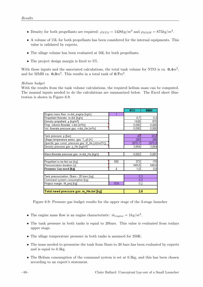
Results
• Density for both propellants are required: ρNTO = 1428kg/m3 and ρMMH = 875kg/m3.
• A volume of 15L for both propellants has been considered for the internal equipments. Thisvalue is validated by experts.
• The ullage volume has been evaluated at 50L for both propellants.
• The project design margin is fixed to 5%.
With those inputs and the associated calculations, the total tank volume for NTO is ca. 0.4m2,and for MMH ca. 0.3m2. This results in a total tank of 0.7m2.
Helium budgetWith the results from the tank volume calculations, the required helium mass can be computed.The manual inputs needed to do the calculations are summarized below. The Excel sheet illus-tration is shown in Figure 6.9.
Figure 6.9: Pressure gas budget results for the upper stage of the 3-stage launcher
• The engine mass flow is an engine characteristic: mengine = 1kg/m3.
• The tank pressure in both tanks is equal to 20bars. This value is evaluated from todaysupper stage.
• The ullage temperature pressure in both tanks is assumed for 250K.
• The mass needed to pressurize the tank from 5bars to 20 bars has been evaluated by expertsand is equal to 0.3kg.
• The Helium consumption of the command system is set at 0.3kg, and this has been chosenaccording to an expert’s statement.
- 68 - Claire Ballard: Conceptual Lay-out of a Small Launcher
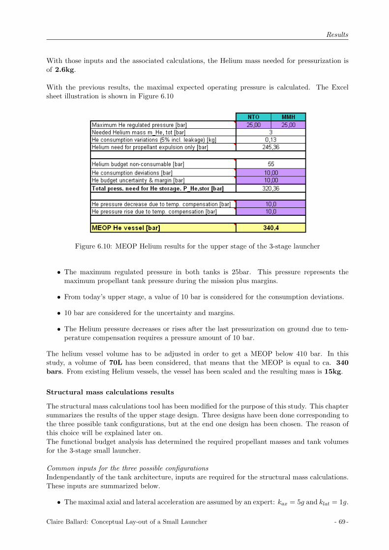
Results
With those inputs and the associated calculations, the Helium mass needed for pressurization isof 2.6kg.
With the previous results, the maximal expected operating pressure is calculated. The Excelsheet illustration is shown in Figure 6.10
Figure 6.10: MEOP Helium results for the upper stage of the 3-stage launcher
• The maximum regulated pressure in both tanks is 25bar. This pressure represents themaximum propellant tank pressure during the mission plus margins.
• From today’s upper stage, a value of 10 bar is considered for the consumption deviations.
• 10 bar are considered for the uncertainty and margins.
• The Helium pressure decreases or rises after the last pressurization on ground due to tem-perature compensation requires a pressure amount of 10 bar.
The helium vessel volume has to be adjusted in order to get a MEOP below 410 bar. In thisstudy, a volume of 70L has been considered, that means that the MEOP is equal to ca. 340bars. From existing Helium vessels, the vessel has been scaled and the resulting mass is 15kg.
Structural mass calculations results
The structural mass calculations tool has been modified for the purpose of this study. This chaptersummarizes the results of the upper stage design. Three designs have been done corresponding tothe three possible tank configurations, but at the end one design has been chosen. The reason ofthis choice will be explained later on.The functional budget analysis has determined the required propellant masses and tank volumesfor the 3-stage small launcher.
Common inputs for the three possible configurationsIndenpendantly of the tank architecture, inputs are required for the structural mass calculations.These inputs are summarized below.
• The maximal axial and lateral acceleration are assumed by an expert: kax = 5g and klat = 1g.
Claire Ballard: Conceptual Lay-out of a Small Launcher - 69 -

Results
• The NTO propellant is placed on the top in the common bulkhead configuration and inthe sphere in the spherical configuration. The propellant mass, tank volume and ullagepressure are the ones used in the functional budget: mNTO = 448kg, VNTO = 430L andpull,NTO,CB = 20bar in the common bulkhead configuration and pull,NTO,Sph = 20.5bar inthe spherical configuration.
• The MMH propellant is placed on the bottom or in the cylinder. The propellant mass, tankvolume and ullage pressure are the ones used in the functional budget: mMMH = 212kg,VMMH = 354L and pull,MMH,CB = 20, 5bar in the common bulkhead configuration andpull,MMH,Sph = 20bar in the spherical-cylinder configuration.
• The characteristics of the structural material have to be implemented. The Aluminum2219 and the CFRP M40/6376 sandwich are used. For the Aluminum, the required inputsare: yield stress σAlu = 358N/mm2, modulus of elasticity E = 72000N/mm2 and densityρAlu = 2851kg/m3. Concerning the composite materials, the following inputs are defined:modulus of elasticity ECFRP = 96386N/mm2, core density ρcore = 50kg/m3 and skin densityρskin = 2296kg/m3.
• The payload mass is fixed to 250kg.
• The fairing mass is calculated from the AVUM fairing. As the considered payload is sixtimes smaller than the AVUM payload, the payload mass is considered 3 times smaller. Asthe AVUM fairing mass is equal to 560kg, in this study it has been considered a fairing of180kg.
The load-bearing common bulkhead tank architectureAs the tanks are parts of the structure, the radius of the stage is the radius of the tank. A radiusof 500mm has been considered for this configuration. With the tank volume and the tank radiusit is possible to automatically calculate the geometry of the tank. The length of the cylinder anddomes as well as the surfaces of the different parts of the tanks are summarized in Table 6.16
Tank 1 Tank 2
Cylinder radius [mm] 500 500Cylinder length [mm] 77 451Dome length [mm] 354 354Cylinder surface [m2] 0.24 1.42Dome surface [m2] 0.95 0.95
Table 6.16: Tank geometrical characteristics, Common Bulkhead load bearing configuration
For the calculations of the axial fluxes, the diameter and length of the different sections arerequired. The diameter of all the section is the diameter of the tank (1000mm). The lengthof the section, which is the fairing length, is 3200mm. The section 2, which is the length ofthe intermediate structure, is 750mm long and the section 3, which the length of the interstagestructure, is 1460mm long. These dimensions have been chosen regarding the place needed for allthe components and tank length, furthermore the interstage length (section 3) has been chosenin order to respect an angle of minimum 10 degrees between the separation system and the exitnozzle part. The axial fluxes are shown in Figures 6.11.
The structural mass calculations results are shown in Figures 6.12 and 6.13. The calculationmethod is the one presented in chapter 3, section 5.
The total structural mass of the upper stage is 191.7kg. This mass does not include thefairing, payload, avionics and subsystems masses.
- 70 - Claire Ballard: Conceptual Lay-out of a Small Launcher

Results
Figure 6.11: Axial fluxes, common bulkhead load bearing tank, 3-stage launcher
Figure 6.12: Structural mass part 1, common bulkhead load bearing tank, 3-stage launcher
The non load-bearing common bulkhead tank architectureThe space between the tank and the structure has been considered equal to 150mm. This assump-tion has been made regarding an existing upper stage. A diameter of 1200mm has been chosen,and so the tank radius was deducted to be equal to 450mm. The length of the cylinder and domesas well as the surfaces of the different parts of the tanks are summarized in Table 6.17
Tank 1 Tank 2
Cylinder radius [mm] 450 450Cylinder length [mm] 252 557Dome length [mm] 318 318Cylinder surface [m2] 0.71 1.57Dome surface [m2] 0.77 0.77
Table 6.17: Tank geometrical characteristics, common Bulkhead non-load bearing configuration
For the calculations of the axial fluxes, the diameter and length of the different section arerequired. The diameter of the sections is 1200mm. The length of the section 1, which is the fairing
Claire Ballard: Conceptual Lay-out of a Small Launcher - 71 -
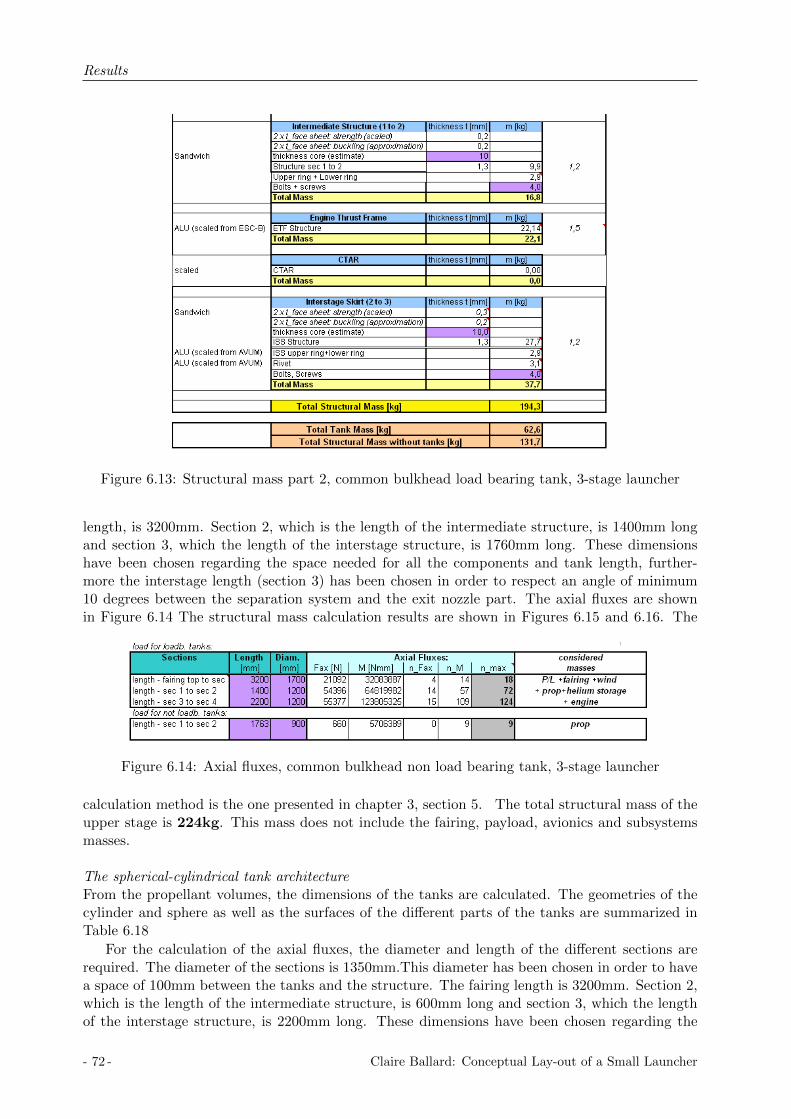
Results
Figure 6.13: Structural mass part 2, common bulkhead load bearing tank, 3-stage launcher
length, is 3200mm. Section 2, which is the length of the intermediate structure, is 1400mm longand section 3, which the length of the interstage structure, is 1760mm long. These dimensionshave been chosen regarding the space needed for all the components and tank length, further-more the interstage length (section 3) has been chosen in order to respect an angle of minimum10 degrees between the separation system and the exit nozzle part. The axial fluxes are shownin Figure 6.14 The structural mass calculation results are shown in Figures 6.15 and 6.16. The
Figure 6.14: Axial fluxes, common bulkhead non load bearing tank, 3-stage launcher
calculation method is the one presented in chapter 3, section 5. The total structural mass of theupper stage is 224kg. This mass does not include the fairing, payload, avionics and subsystemsmasses.
The spherical-cylindrical tank architectureFrom the propellant volumes, the dimensions of the tanks are calculated. The geometries of thecylinder and sphere as well as the surfaces of the different parts of the tanks are summarized inTable 6.18
For the calculation of the axial fluxes, the diameter and length of the different sections arerequired. The diameter of the sections is 1350mm.This diameter has been chosen in order to havea space of 100mm between the tanks and the structure. The fairing length is 3200mm. Section 2,which is the length of the intermediate structure, is 600mm long and section 3, which the lengthof the interstage structure, is 2200mm long. These dimensions have been chosen regarding the
- 72 - Claire Ballard: Conceptual Lay-out of a Small Launcher

Results
Figure 6.15: Structural mass part 1, common bulkhead non load bearing tank, 3-stage launcher
Figure 6.16: Structural mass part 2, common bulkhead non load bearing tank, 3-stage launcher
Claire Ballard: Conceptual Lay-out of a Small Launcher - 73 -
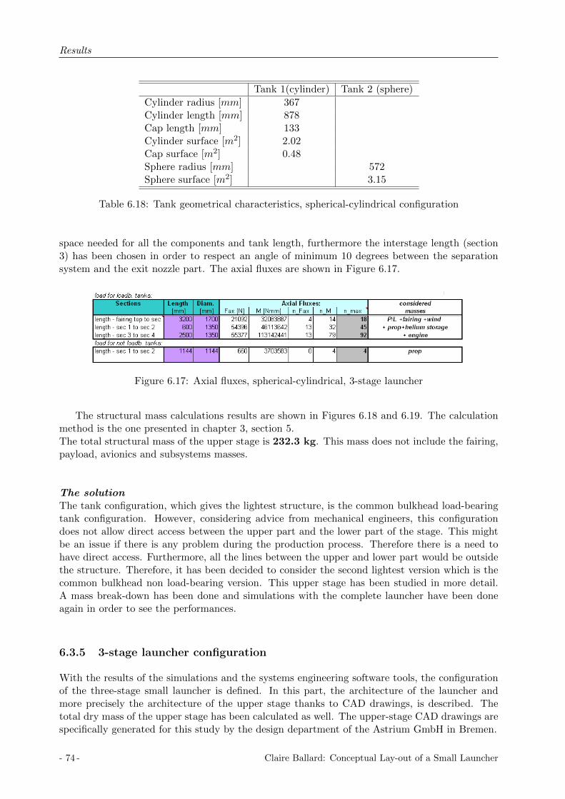
Results
Tank 1(cylinder) Tank 2 (sphere)
Cylinder radius [mm] 367Cylinder length [mm] 878Cap length [mm] 133Cylinder surface [m2] 2.02Cap surface [m2] 0.48Sphere radius [mm] 572Sphere surface [m2] 3.15
Table 6.18: Tank geometrical characteristics, spherical-cylindrical configuration
space needed for all the components and tank length, furthermore the interstage length (section3) has been chosen in order to respect an angle of minimum 10 degrees between the separationsystem and the exit nozzle part. The axial fluxes are shown in Figure 6.17.
Figure 6.17: Axial fluxes, spherical-cylindrical, 3-stage launcher
The structural mass calculations results are shown in Figures 6.18 and 6.19. The calculationmethod is the one presented in chapter 3, section 5.The total structural mass of the upper stage is 232.3 kg. This mass does not include the fairing,payload, avionics and subsystems masses.
The solutionThe tank configuration, which gives the lightest structure, is the common bulkhead load-bearingtank configuration. However, considering advice from mechanical engineers, this configurationdoes not allow direct access between the upper part and the lower part of the stage. This mightbe an issue if there is any problem during the production process. Therefore there is a need tohave direct access. Furthermore, all the lines between the upper and lower part would be outsidethe structure. Therefore, it has been decided to consider the second lightest version which is thecommon bulkhead non load-bearing version. This upper stage has been studied in more detail.A mass break-down has been done and simulations with the complete launcher have been doneagain in order to see the performances.
6.3.5 3-stage launcher configuration
With the results of the simulations and the systems engineering software tools, the configurationof the three-stage small launcher is defined. In this part, the architecture of the launcher andmore precisely the architecture of the upper stage thanks to CAD drawings, is described. Thetotal dry mass of the upper stage has been calculated as well. The upper-stage CAD drawings arespecifically generated for this study by the design department of the Astrium GmbH in Bremen.
- 74 - Claire Ballard: Conceptual Lay-out of a Small Launcher

Results
Figure 6.18: Structural mass part 1, spherical-cylindrical, 3-stage launcher
Figure 6.19: Structural mass part 2, spherical-cylindrical, 3-stage launcher
Claire Ballard: Conceptual Lay-out of a Small Launcher - 75 -
Results
The architecture
The three-stage small launcher is composed of the Zefiro 23 stage, the Zefiro 9 stage and an up-per stage specially designed for this study. A complete drawing of the launcher is represented inFigure 6.20. No changes are done on the Zefiro stages, the complete definition of the upper stageis done in the following part.
For the upper stage with the AESTUS 3kN engine, the Common Bulkhead configuration as anon-load bearing propellant tank is chosen regarding the structural mass and mostly, regardingthe fact this configuration allows an access between the lower and upper parts of the launcher. Thestage diameter is 1200mm and the cylindrical tank diameter is equal to 900mm. This facilitatesa space of 150mm between the tank shells and the stage structure. The interstage between thesecond stage and the upper stage has a conical shape; the big diameter is equal to 1900mm, whichis the Zefiro stage diameter and the small diameter, is equal to 1200mm. The fairing is placed onthe top of the upper-stage. The fairing length is equal to 3200mm and the maximal diameter ofthe fairing is equal to 1700mm. The fairing geometry is chosen regarding the existing fairing ofthe VEGA launcher.
Figure 6.21and 6.22 illustrates the upper stage concepts with all components, explained below.The technical drawing of the upper stage can be found in Annex E. The upper cone is designedto be the upper interface to the payload and its design is based on an existing payload adapter.The big diameter of the cone is equal to the stage diameter and the small diameter is equal to800mm. Additionally, an avionic platform is implemented on the top of the stage. This platformenables the attachments of all the avionics equipments and a vessel is placed in the middle of theplatform. The avionics platform is a circular band of the size 200mm. The attitude control systemis the one used on the VEGA launcher: RACS (Roll and Attitude Control System). This systemrequires a hydrazine vessel with 38 kg of Hydrazine. This vessel has a diameter of 482mm andis placed in the middle of the avionics platform. The two thruster cluster modules of the RACSsystem are dimetrically opposite placed at the top of the stage.At the stage’s interstage structure, the common bulkhead NTO/MMH tank is attached thanks tothe CTAR. The engine thrust frame is directly attached to the lower cylinder and the AESTUS3kN engine is attached to the engine thrust frame. The pressure control system (PCA) is attachedto the engine thrust frame as well as the helium vessel. 70 liters of helium is required as explainedin the helium budget calculations. The helium vessel configuration is cylindrical with two spher-ical domes. One helium vessel with a diameter of 430mm is needed. The interstage structurerepresents the connection with the previous stage Zefiro 9. The total length of the upper stage in-cluding the cone, is 3410mm and the total length of the launcher including the fairing is 17,901mm.
In Appendix E, the fluid schematics of the upper stage is illustrated. The pressurization sys-tem, the RACS and all the different feed lines are represented as well as the propellant fill anddrain valves required for the fueling on ground.
The mass breakdown
After the definition of the upper stage architecture, the total mass has to be evaluated. TheStructural Calculations Software Tool has enabled the evaluation of the tank mass and the mainstructural component masses, but there is still the need to evaluate the mass of the remainingsubsystems. That is why a mass breakdown has been established for the upper stage. The differentsubsystem masses have been chosen regarding existing studies and validated by an expert. Thefollowing items have been considered in the mass breakdown [12]:
• propulsion system
- 76 - Claire Ballard: Conceptual Lay-out of a Small Launcher
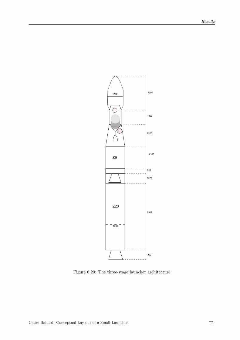
Results
Figure 6.20: The three-stage launcher architecture
Claire Ballard: Conceptual Lay-out of a Small Launcher - 77 -

Results
Figure 6.21: 3D drawing of the upper stage, 3-stage launcher
Figure 6.22: Section cut of the upper stage, 3-stage launcher
- 78 - Claire Ballard: Conceptual Lay-out of a Small Launcher

Results
• equipped tanks (propellant tank, helium vessel, hydrazine vessel)
• fluid masses (helium, hydrazine, reserve propellant)
• structures (stage structure, interstage skirt, equipments)
• avionics
• RACS [20]
• separation system
• subsystems (thermal subsystems, neutralization system, feed lines supports, electrical sys-tem)
The mass breakdown table is represented on the following table. Only the main items presentedbefore are included in this table. They are the relevant components for an upper-stage, thesubsystems are defined but not explained in detail.
• The mass of the 3kN thrust AESTUS engine is 20kg.
• The calculated mass of the common bulkhead tank thanks to the Structural CalculationMass Tool is 53.5kg.
• The 70liters of helium are stored in one vessel of 15kg. This mass is evaluated by scalingthe existing vessel.
• The hydrazine vessel is the one used for the VEGA launcher, its mass is 8.45kg.
• The helium mass evaluated by the Helium budget is 4kg.
• The Hydrazine mass is the one considered for the VEGA launcher and it is 38kg.
• Regarding the propellant budget, 163kg are considered as reserve propellant.
• The structural mass is calculated with the Structural Calculations Tool. The stage structureis equal to 29.6kg and the interstage skirt is equal to 46.4kg. The upper cone, the avionicsplatform, the CTAR and the ETF masses have been evaluated by scaling from existingsystems.
• The avionics mass considered is that of the VEGA launcher, 96kg.
• The RACS system is that of the VEGA launcher. The total mass is 41.75kg.
• The separation system is evaluated by scaling from existing systems, 14.2kg.
• The subsystem mass is scaled regarding the VEGA launcher, 57 kg have been consideredfor the total subsystem mass.
Finally, by summing up all these components, the total upper stage dry mass is equal to 713.7kg, with 60.6 kg of jettisonable mass.
Claire Ballard: Conceptual Lay-out of a Small Launcher - 79 -

Results
NAME OF PRODUCT JETTISONABLE MASS [kg]MASS [kg]
Equipped tank 76.95Equipped propellant tanks 53.5Helium vessel 15Hydrazine vessel 8.45
Fluid mass 705Helium 4Hydrazine 38Reserve propellant 163Nominal propellant 500
Structure 46.4 109.1Stage structure 29.6Interstage skirt 46.4Additional structural mass 79.5
Upper cone structure 33Avionics platform 16CTAR 11.3Engine thrust frame 19.2
Avionics 96RACS 41.75
Pressure transducers 0.5Pyrotechnic valves 1Feed line and drain valve 0.65Turbing kit 2Pipe support brackets + bolts 2.7Thruster cluster module 27Aerothermal cover 7.9
Separation system 14.2Pyrojacks 7.5Pyro lines 5.4RMV 1.3
Propulsion system 67.1Engine 20Pressure control assembly 12Feed lines 7Pressurization lines 6.5Passivation system 3.4Actuators 15Fill and drain coupling 3.2
Subsystems 57.2Thermal subsystems 18.4Neutralisation system 7.5Supports 20.7Electrical system 11.6
TOTAL STAGE DRY MASS 60.6 653.1FAIRING 180TOTAL UPPER STAGE MASS 240.6 1153.1
Table 6.19: Mass breakdown of the upper stage for the 3-stage launcher
- 80 - Claire Ballard: Conceptual Lay-out of a Small Launcher

Results
Stage 1: Z23 Stage 2: Z9 Stage 3
Isp [s] 289 295 321Thrust [kN ] 1196 225 3Propellant mass [kg] 23,906 10,115 500Dry mass [kg] 1,845 833 653.1Interstage mass [kg] 60.6Length [m] 7454 3547 3600Diameter [m] 1.9 1.9 1.2
Table 6.20: The three-stage launcher characteristics
6.3.6 Small launcher simulation
Simulations have been run with the designed upper stage. The characteristics of the Zefiro 23and Zefiro 9 have been implemented on the Matlab code. The propellant mass of the third stagehas been considered equal to 500kg which is the nominal propellant mass. Regarding the massbreakdown, the structural mass has been considered equal to 653.1kg and the interstage mass isequal to 60.6kg. The fairing is equal to 180 kg.
With this launcher configuration, the Matlab simulations show that it is possible to place330kg into the elliptical transfer orbit 200km perigee - 700km apogee. As there is a need ofaround 35kg of propellant in order to realize the circularization, the payload which can be placedinto the circular orbit with a radius of 700km, is around 295kg.
The simulation is represented in the following figures. Figure 6.23 shows the variation of alti-tude, velocity and flight path angle as functions of time and the altitude as a function of velocity,from the launch pad to the elliptical orbit. Each color corresponds to one stage:
• the curve red is the first stage
• the blue curve is the second stage
• the green curve is the upper stage
Figure 6.24 represents the variations of the altitude, velocity and flight path angle as functions oftime and the altitude as a function of velocity, from the launch pad to the circular orbit. Eachcolor corresponds to a certain part of the trajectory:
• the blue curve is from the launch pad to the elliptical orbit at burnout of the upper stage
• the red curve corresponds to the trajectory in orbit when the thrust is equal to zero
• the green curve corresponds to the trajectory in the circular orbit
The upper stage re-ignition happens when the spacecraft reaches the orbit apogee. Figure 6.25represents the variations of the mass, thrust, dynamic pressure, lateral and longitudinal velocityas functions of time. The lateral velocity is the red curve and the longitudinal velocity is the blueone.
Claire Ballard: Conceptual Lay-out of a Small Launcher - 81 -

Results
0 200 400 600 8000
50
100
150
200Altitude vs Time
Time [s]
Altitu
de
[km
]
0 200 400 600 8000
2000
4000
6000
8000Speed vs Time
Time [s]
Ve
locity [
m/s
]
0 200 400 600 800−50
0
50
100Angle vs Time
Time [s]
An
gle
[d
eg
]
0 2 4 6 80
50
100
150
200speed vs altitude
speed [km/s]
altitu
de
[km
]
Figure 6.23: 3-stage launcher simulation from launch pad to the elliptical orbit
0 1000 2000 3000 40000
200
400
600
800Altitude vs Time
Time [s]
Altitu
de
[km
]
0 1000 2000 3000 40000
2000
4000
6000
8000Speed vs Time
Time [s]
Ve
locity [
m/s
]
0 1000 2000 3000 4000−50
0
50
100Angle vs Time
Time [s]
An
gle
[d
eg
]
0 2 4 6 80
200
400
600
800speed vs altitude
speed [km/s]
altitu
de
[km
]
Figure 6.24: 3-stage launcher simulation from launch pad to the circular orbit
- 82 - Claire Ballard: Conceptual Lay-out of a Small Launcher

Results
0 200 400 600 8000
1
2
3
4x 10
4 Mass vs time
Time [s]
Ma
ss [
kg
]
0 200 400 600 8000
5
10
15x 10
5 Thrust vs Time
Time [s]
Th
rust
[N]
0 200 400 600 8000
20
40
60
80
100dynamic pressure vs Time
Time [s]
dyn
am
ic p
ressu
re [
]
0 200 400 600 800−5000
0
5000
10000speed vs time
time [s]
sp
ee
d [
m/s
]
Figure 6.25: 3-stage launcher simulation, other characteristics
6.4 2-stage Launcher Solution
The purpose is to propose a solution with two liquid stages. The first stage with liquid propulsionis from an existing stage, the upper stage is designed in the course of the study with an enginedeveloped in the company. Two existing liquid stages have been studied: the first stage of theSoyuz launcher, and the second stage of the Zenit launcher. Another engine has been studied aswell. It is the engine derived form the Zenit launcher which is under investigation as explainedpreviously. The results with these two boosters are presented in the following section.
6.4.1 Initial values, constants and inputs
As explained previously in the method part, existing liquid stages with enough thrust to lift offare too big for the purpose of the small launcher. That is why it has been decided to reducetheir masses by decreasing the amount of propellant and so decreasing as well the structuralmass. Concerning the first stage, the thrust and the specific impulse are considered constant andthe structural index varies as a function of propellant mass. The curve, which represents thisvariation, is the optimum curve presented in the existing stages section. The structural mass ofthe upper stage is calculated from the propellant mass and the thrust of the upper stage. Thespecific impulse is constant and equal to 320.9.
The initial velocity is set to zero as the required orbit has an inclination of 90 degrees. Thedrag coefficient is constant and equal to 0.3. The reference area is equal to 6.6052m2 for theSOYUZ first stage, which corresponds to a diameter of 2.9 meters, it is equal to 11.9459m2 forthe ZENIT first stage, which corresponds to a diameter of 3.9 meters, and it is equal to 7.0686m2
for the new Zenit engine, which corresponds to a diameter of 3 meters. The last diameter is anassumption which seems reasonable.
The payload is constant and equal to 250 kg.
The inputs are
• the beginning and the end of the gravity turn program: t1 and t2
Claire Ballard: Conceptual Lay-out of a Small Launcher - 83 -

Results
• the propellant mass in the first stage: mp,1
• the propellant mass in the third stage: mp,2
• the thrust in the third stage: F2
The optimization program has 5 parameters: two parameters from the gravity turn program,two parameters from the propellant mass in the three stages and one parameter for the thrust inthe upper stage.
v1 =(t1 t2 mp,1 mp,2 F2
)(6.5)
6.4.2 Optimal launcher
The characteristics of the three studied stages are summarized in Table 6.21.
Entity Soyuz, stage 1 Zenit, stage 2 Zenit, booster
Isp [s] 319 349 330Thrust [kN ] 990 912 849mp [kg] 93,311 80,600mdry [kg] 6454 8900mengine [kg] 1,400 1,500 1080D [m] 2.9 3.9 3
Table 6.21: Chosen liquid stages characteristics
Solution 1: Soyuz stage + Upper stage
The configuration which has been studied is to have the first stage of the Soyuz launcher in thefirst stage of the small launcher and a liquid upper stage. As explained in the method, the purposewas, by keeping the thrust and the specific impulse constant, to optimize the propellant mass inthe first stage and the the propellant mass and the thrust in the upper stage. In this optimizationthe payload is fixed and equal to 250kg. The optimization is done on the gravity turn program,the amount of propellant in the first and second stage and the thrust in the upper stage. Thethrust and the specific impulse in the first stage are fixed, the structural mass was calculatedthanks to the optimum curve of the structural index and the curve representing the engine massas function of the thrust. The specific impulse in the upper stage is fixed, the structural mass wascalculated from the functions depending on the thrust and the propellant mass. Several possibili-ties are studied depending on the amount of propellant in the first stage. The criteria for the bestsolution is the highest payload ratio.
From several simulations, it has been noticed that this configuration can not put 250kg of payloadin the desired orbit. Therefore, other simulations have been run decreasing the amount of payload.A solution has been found with 150kg of payload. The launcher characteristics with this solutionare written in the table below.
Propellant mass [kg] Dry mass [kg] Thrust [kN ] Payload [kg] Payload ratio [%]1 2 1 2 1 2
58,887 2,383 5,280 1,209 990 27 150 0.221
Table 6.22: Liquid, Solution 1, Soyuz stage and liquid upper stage
The simulations with the Soyuz launcher do not give good enough results.
- 84 - Claire Ballard: Conceptual Lay-out of a Small Launcher

Results
Solution 2: Zenit stage + Upper stage
Another configuration has been studied with the second stage of the Zenit launcher. The purposeis to optimize the amount of propellant in the first stage and the upper stage and the thrust inthe upper stage with a payload mass fixed and equal to 250kg. The optimization is done on thegravity turn program the amount of propellant in the first and second stage and the thrust inthe upper stage. The thrust and the specific impulse in the first stage are fixed, the structuralmass is calculated thanks to the optimum curve of the structural index. The specific impulse inthe upper stage is fixed, the structural mass is calculated from functions depending on the thrustand the propellant mass. As before, several possibilities are studied depending on the amount ofpropellant in the first stage, the selection criteria is to get the highest payload ratio. The resultsare shown in the following table.
Propellant mass [kg] Dry mass [kg] Thrust [kN ] Payload [kg] Payload ratio [%]1 2 1 2 1 2
43,023 1,284 5,064 770 912 12.3 250 0.49641,536 1,507 4,955 840 912 15 250 0.50940,620 1,850 4,943 944 912 18.5 250 0.51439,745 2,329 4,930 1084 912 23.3 250 0.517
Table 6.23: Liquid, Solution 2, Zenit stage and liquid upper stage
When decreasing the propellant mass in the first stage, the upper stage needs to have betterperformance and therefore to increase its thrust and propellant mass. The purpose was to see atwhat point the payload ratio started decreasing and so to have the best solution. As can be seen inTable 6.23, in the last row the payload ratio is the highest which was possible to get, which meansthat the best possible small launcher configuration is to have a first stage with around40,000kg ofpropellant, and an upper stage with around 23kN thrust and 2,300kg of propellant mass.
However, in this configuration the total thrust takes into account the steering engines of theZenit launcher. But, the thrust from these engines is non-propulsive as it is not longitudinalthrust but it is used for attitude control. Therefore, another study has been done by using theengine under investigation derived from the Zenit main engine.
Solution 3: Zenit booster + Upper stage
The same simulations as explained previously, have been done by using the new Zenit engine. Thisengine is derived from the main engine of the Zenit second stage. The purpose is to developed anengine usable in a first stage. In the simulations, the thrust and specific impulse of the first stagewere constant whereas the structural mass was calculated thanks to the thrust and the amountof propellant. Concerning the upper stage, the specific impulse was constant, the structural masswas calculated thanks to the thrust and the propellant mass. The variables are the amount ofpropellant in the 2 stages, the thrust in the upper stage, and the times of the gravity turn program.A solution has been found with 150kg of payload. The results are shown in the table below.
Propellant mass [kg] Dry mass [kg] Thrust [kN ] Payload [kg] Payload ratio [%]1 2 1 2 1 2
47,000 1,989 5,268 991 849 18.4 150 0.271
Table 6.24: Liquid, Solution 3, Zenit booster and liquid upper stage
Claire Ballard: Conceptual Lay-out of a Small Launcher - 85 -

Results
6.4.3 The retained solution
The best solution among the possible configurations exposed previously is chosen based on thepayload ratio. So the configuration, which gives the highest payload ratio, is the one which usesthe Soyuz stage as a first stage. However, as explained previously, in the simulations, the thrust ofthe Soyuz stage takes into account the thrust from the steering engines, so the considered thrustis too large compared to reality. It has been decided to choose the new Zenit engine which isstill under investigation even if from the simulations this configuration could place into orbit only150kg.Concerning the upper stage, the engine under investigation in the company, which is the closestone from the simulation results, is a 22kN thrust engine. The exit nozzle of this engine is notoptimized, and so the specific impulse is a bit smaller than the one considered in the simulations,and it is equal to 316s. The characteristics of this small launcher are summarized in Table 6.25.
Zenit booster Upper stage
Isp [s] 330 316Thrust [kN ] 849 22mp [kg] 47,000 2,000
Table 6.25: The 2-stage launcher solution
The thrust and the amount of propellant of the upper stage are fixed, the structure of theupper stage can be designed in more detail for this solution. The structure of the first stage usingthe Zenit booster will be designed as well.
6.4.4 The Zenit new design
The first stage of the 2-stage small launcher uses the Zenit engine which is under investigation.This stage needs to be entirely designed. This section explains the new design of the Zenit stagewith the functional budget and the structural mass calculations.
The engine
The engine of the Zenit stage is composed of the booster engine which is derived from the mainengine of the Zenit second stage. The characteristics of this engine, namely mixture ratio, enginemass, length, diameter, thrust and specific impulse, are written in the table below.
Zenit boosterRD-120K
Thrust [kN ] 849Isp [s] 330Engine mass [kg] 1080MR [−] 2.6Mass flow [kg/s] 20.8Diameter [mm] 1400Length [mm] 2400
Table 6.26: The Zenit booster characteristics
The functional design has been done using the Excel tool presented in chapter 3, section 4.This section summarizes the results.
- 86 - Claire Ballard: Conceptual Lay-out of a Small Launcher

Results
Propellant budgetThe manual inputs for the propellant budget are summarized below. The Excel sheet illustrationis shown in Figure 6.26.
Figure 6.26: Propellant budget results for the first stage of the 2-stage launcher
• The number of boosts is equal to 1
• The propellant mixture ratio is preset by the engine characteristics and so MR=2.6
• The nominally used propellant is adapted from the simulations and so mprop = 47000kg
• The value of a performance reserve is evaluated by an expert and it has been considered tobe 2% of the nominally used propellant
• The propellant mass for the geometrical residuals is calculated considering that 10 liters ofeach propellant is lost in geometrical residuals.
• The project design margin is set up to 1%
• The value of 0.7% is used for the loading process inaccuracy and this value is estimated byexperts
With those inputs and the associated calculations, the total loaded propellant for LOX is ca.35278kg, and for Kerosene ca. 13553kg. So the total loaded propellant is 48831kg.
Tank volumeWith the results from the propellant budget, the tank volume can be calculated as explained inchapter 3.5. The manual inputs needed to do the calculations are summarized below. The Excelsheet illustration is shown in Figure 6.27.
• Both propellant densities are required: ρLOX = 1142kg/m3 and ρKerosene = 803kg/m3.
• A volume of 15L for both propellants has been considered for the internal equipment. Thisvalue is validated by experts.
• The ullage volume has been considered to be 50L for both propellants.
• The project design margin is fixed to 5%.
Claire Ballard: Conceptual Lay-out of a Small Launcher - 87 -

Results
Figure 6.27: Tank volume results for the first stage of the 2-stage launcher
With those inputs and the associated calculations, the total tank volume for LOX is ca. 33m3,and for Kerosene ca. 18m3. This results in a total tank of 51m3.
Helium budgetWith the results from the tank volume calculations, the required helium mass can be computed.The manual inputs needed to do the calculations are summarized below. The Excel sheet illus-tration is shown in Figure 6.28.
Figure 6.28: Pressure gas budget results for the first stage of the 2-stage launcher
• The engine mass flow is an engine characteristic: mengine = 20.8kg/m3.
• The tank pressure in both tanks is considered equal to 4bar.
• The ullage temperature in both tanks is assumed for 175K.
- 88 - Claire Ballard: Conceptual Lay-out of a Small Launcher
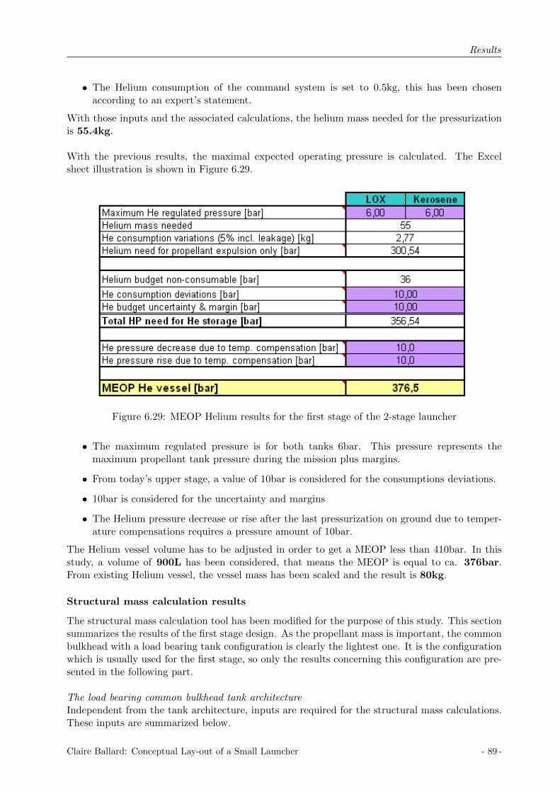
Results
• The Helium consumption of the command system is set to 0.5kg, this has been chosenaccording to an expert’s statement.
With those inputs and the associated calculations, the helium mass needed for the pressurizationis 55.4kg.
With the previous results, the maximal expected operating pressure is calculated. The Excelsheet illustration is shown in Figure 6.29.
Figure 6.29: MEOP Helium results for the first stage of the 2-stage launcher
• The maximum regulated pressure is for both tanks 6bar. This pressure represents themaximum propellant tank pressure during the mission plus margins.
• From today’s upper stage, a value of 10bar is considered for the consumptions deviations.
• 10bar is considered for the uncertainty and margins
• The Helium pressure decrease or rise after the last pressurization on ground due to temper-ature compensations requires a pressure amount of 10bar.
The Helium vessel volume has to be adjusted in order to get a MEOP less than 410bar. In thisstudy, a volume of 900L has been considered, that means the MEOP is equal to ca. 376bar.From existing Helium vessel, the vessel mass has been scaled and the result is 80kg.
Structural mass calculation results
The structural mass calculation tool has been modified for the purpose of this study. This sectionsummarizes the results of the first stage design. As the propellant mass is important, the commonbulkhead with a load bearing tank configuration is clearly the lightest one. It is the configurationwhich is usually used for the first stage, so only the results concerning this configuration are pre-sented in the following part.
The load bearing common bulkhead tank architectureIndependent from the tank architecture, inputs are required for the structural mass calculations.These inputs are summarized below.
Claire Ballard: Conceptual Lay-out of a Small Launcher - 89 -

Results
• The maximal axial and lateral acceleration are assumed by an expert: kax = 5g and klat = 1g.
• The LOX propellant is placed on the top of the common bulkhead configuration. Thepropellant mass, tank volume and ullage pressure are the ones used in the functional budget:mLOX = 35449kg, VLOX = 33215L, pull,LOX = 4bar.
• The Kerosene propellant is placed on the bottom of the common bulkhead configuration.The propellant mass, tank volume and ullage pressure are the ones used in the functionalbudget: mKerosene = 13675kg, VKerosene = 18229L, pull,Kerosene = 4.5bar.
• The characteristics of the structural material have to be implemented. Aluminum 2219 andthe CFRP M40/6376 sandwich are used. For the aluminum, the required inputs are: yieldstress σAlu = 358N/mm2, modulus of elasticity E = 72000N/mm2 and density ρAlu =2851kg/m3. Concerning the composite materials, the following inputs are needed: modulusof elasticity ECFRP = 96386N/mm2, core density ρcore = 50kg/m3 and skin density ρskin =2296kg/m3.
• The payload mass takes into account the mass of the upper stage and the payload mass.
As the tanks are part of the structure, the tank radius is the stage radius. The radius whichenables to get the lightest tank structural mass is around 1500mm, so the chosen stage radius is1500mm. No structure is considered above the tank as the top of the tank is directly connected tothe interstage structure with the upper stage. A structure below the tank is considered in orderto protect the helium vessels and equipment. The length of this structure is equal to 1800mm andthe diameter is equal to 3000mm.
The structural mass calculation results are shown in Figure 6.30. The total structural massof the first stage with the new Zenit engine is 1306kg. This mass does not include the subsys-tems. A mass break-down and simulations with the complete launcher have been done once againto see the performances.
6.4.5 The upper stage design
The upper stage needs to be designed in detail. This section presents the functional budget resultsand the structural mass calculations results. First the engine used is presented.
The engine
It has been decided to consider the 22kN thrust engine for the upper stage. The characteristicsof the engine are summarized in the table below.
Entity Value
Oxidizer NTOFuel MMHMixtur Ratio [−] 1.9Mass flow [kg/s] 10Nozzle diameter [mm] 438Engine length [mm] 823
Table 6.27: The 22kN thrust engine characteristics
- 90 - Claire Ballard: Conceptual Lay-out of a Small Launcher

Results
Figure 6.30: Structural mass, Common bulkhead load bearing tank, first stage, 2-stage launcher
Claire Ballard: Conceptual Lay-out of a Small Launcher - 91 -
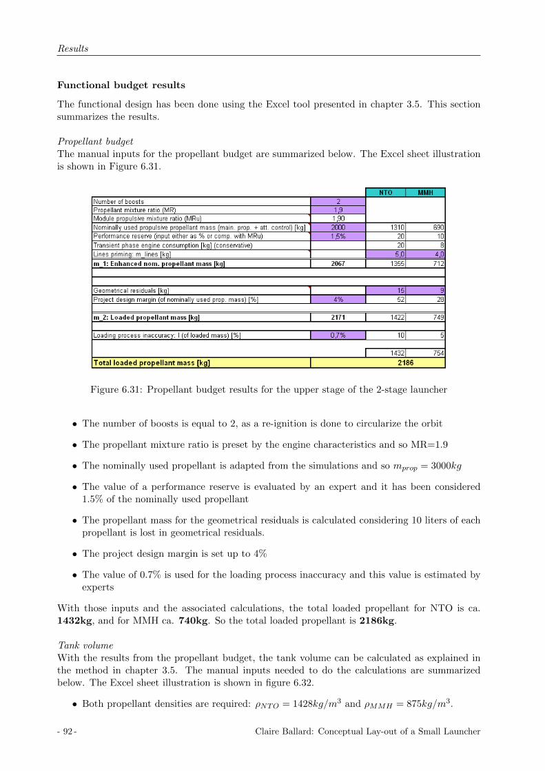
Results
Functional budget results
The functional design has been done using the Excel tool presented in chapter 3.5. This sectionsummarizes the results.
Propellant budgetThe manual inputs for the propellant budget are summarized below. The Excel sheet illustrationis shown in Figure 6.31.
Figure 6.31: Propellant budget results for the upper stage of the 2-stage launcher
• The number of boosts is equal to 2, as a re-ignition is done to circularize the orbit
• The propellant mixture ratio is preset by the engine characteristics and so MR=1.9
• The nominally used propellant is adapted from the simulations and so mprop = 3000kg
• The value of a performance reserve is evaluated by an expert and it has been considered1.5% of the nominally used propellant
• The propellant mass for the geometrical residuals is calculated considering 10 liters of eachpropellant is lost in geometrical residuals.
• The project design margin is set up to 4%
• The value of 0.7% is used for the loading process inaccuracy and this value is estimated byexperts
With those inputs and the associated calculations, the total loaded propellant for NTO is ca.1432kg, and for MMH ca. 740kg. So the total loaded propellant is 2186kg.
Tank volumeWith the results from the propellant budget, the tank volume can be calculated as explained inthe method in chapter 3.5. The manual inputs needed to do the calculations are summarizedbelow. The Excel sheet illustration is shown in figure 6.32.
• Both propellant densities are required: ρNTO = 1428kg/m3 and ρMMH = 875kg/m3.
- 92 - Claire Ballard: Conceptual Lay-out of a Small Launcher
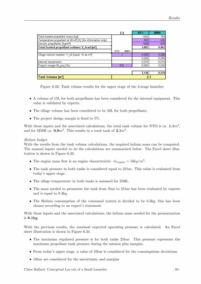
Results
Figure 6.32: Tank volume results for the upper stage of the 2-stage launcher
• A volume of 15L for both propellants has been considered for the internal equipment. Thisvalue is validated by experts.
• The ullage volume has been considered to be 50L for both propellants.
• The project design margin is fixed to 5%.
With those inputs and the associated calculations, the total tank volume for NTO is ca. 1.1m3,and for MMH ca. 0.9m3. This results in a total tank of 2.1m3.
Helium budgetWith the results from the tank volume calculations, the required helium mass can be computed.The manual inputs needed to do the calculations are summarized below. The Excel sheet illus-tration is shown in Figure 6.33.
• The engine mass flow is an engine characteristic: mengine = 10kg/m3.
• The tank pressure in both tanks is considered equal to 21bar. This value is evaluated fromtoday’s upper stage.
• The ullage temperature in both tanks is assumed for 250K.
• The mass needed to pressurize the tank from 5bar to 21bar has been evaluated by expertsand is equal to 0.3kg.
• The Helium consumption of the command system is decided to be 0.3kg, this has beenchosen according to an expert’s statement.
With those inputs and the associated calculations, the helium mass needed for the pressurizationis 8.1kg.
With the previous results, the maximal expected operating pressure is calculated. An Excelsheet illustration is shown in Figure 6.34.
• The maximum regulated pressure is for both tanks 25bar. This pressure represents themaximum propellant tank pressure during the mission plus margins.
• From today’s upper stage, a value of 10bar is considered for the consumptions deviations.
• 10bar are considered for the uncertainty and margins
Claire Ballard: Conceptual Lay-out of a Small Launcher - 93 -

Results
Figure 6.33: Pressure gas budget results for the upper stage of the 2-stage launcher
Figure 6.34: MEOP Helium results for the upper stage of the 2-stage launcher
• the Helium pressure decrease or rise after the last pressurization on ground due to temper-ature compensations requires a pressure amount of 10bar.
The Helium vessel volume has to be adjusted in order to get a MEOP lower than 410bar. In thisstudy, a volume of 200L has been considered, that means the MEOP is equal to ca. 360bar.From existing Helium vessel, the vessel mass has been scaled and the result is 50kg.
- 94 - Claire Ballard: Conceptual Lay-out of a Small Launcher

Results
Structural mass calculation results
The Structural Mass Calculation Tool has been modified for the purpose of this study. Thischapter summarizes the results of the upper stage design. Considering the advice of mechanicalengineers about the upper stage tank configuration, the load-bearing common bulkhead config-uration has not been studied as this configuration does not permit any direct access betweenthe lower part and upper part of the stage. Therefore, two designs have been studied, the nonload-bearing common bulkhead configuration and the spherical-cylindrical configuration.The functional budget analysis has determined the required propellant mass and the tank volumesfor the 2-stage small launcher.
Common inputs for the two possible configurationsIndependant from the tank architecture, inputs are required for the structural mass calculations.These inputs are summarized below.
• The maximal axial and lateral acceleration are assumed by an expert: kas = 5g and klat = 1g.
• The NTO propellant is placed on the top in the common bulkhead configuration and inthe sphere in the spherical-cylindrical configuration. The propellant mass, tank volumeand ullage pressure are from the functional budget: mNTO = 1432kg, VNTO = 1118L,pull,NTO,CB = 21bar in the common bulkhead configuration and pull,NTO,Sph = 21.5barinthe spherical configuration.
• The MMH propellant is placed on the bottom in the common bulkhead configuration andin the cylinder in the spherical-cylindrical configuration. The propellant mass, tank vol-ume and ullage pressure are from the functional budget: mMMH = 754kg, VNTO = 970L,pull,MMH,CB = 21.5bar in the common bulkhead configuration and pull,MMH,Sph = 21bar inthe spherical configuration.
• The characteristics of the structural material have to be implemented. Aluminum 2219 andthe CFRP M40/6376 sandwich are used. For the aluminum, the required inputs are: yieldstress σAlu = 358N/mm2, modulus of elasticity E = 72000N/mm2 and density ρAlu =2851kg/m3. Concerning the composite materials, the following inputs are needed: modulusof elasticity ECFRP = 96386N/mm2, core density ρcore = 50kg/m3 and skin density ρskin =2296kg/m3.
• The payload mass is fixed to 250kg.
• The fairing mass is calculated from the AVUM fairing. As the considered payload is sixtimes smaller than the AVUM payload, so the payload mass is considered 3 times smaller.As the AVUM fairing mass is equal to 560kg, in this study it has been considered a fairingof 180kg.
The non load bearing common bulkhead tank architectureRegarding the tank volume, the tank diameter which gives the smaller tank mass is around1200mm, so this diameter of 1200mm has been chosen for the tanks. The space between the tankshells and the structure is equal to 150mm, and so the stage diameter is equal to 1500mm. Thelength of the cylinder and domes, as well as the surfaces of the different parts of the tanks aresummarized in Table 6.28. For the calculations of the axial fluxes, the diameter and length of thedifferent sections are required. The diameter of all the sections is 1500mm. The length of section1, which is the length of the fairing, is 3200mm. Section 2, which is the length of the intermediatestructure, is 1800mm long and section 3, which is the length of the interstage skirt, is 3500mm.These dimensions have been chosen regarding the space needed for all the components and tanklength. The axial fluxes are shown in Figure 6.35.
Claire Ballard: Conceptual Lay-out of a Small Launcher - 95 -
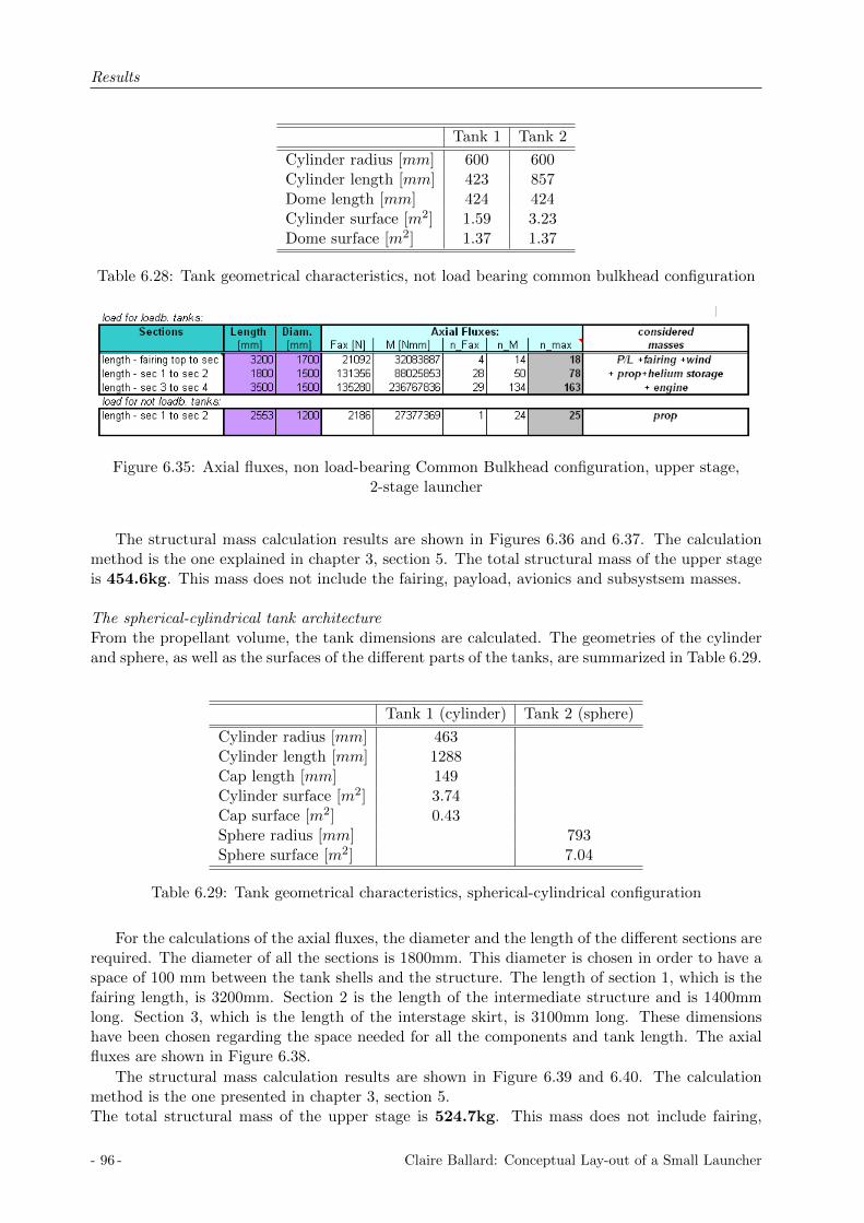
Results
Tank 1 Tank 2
Cylinder radius [mm] 600 600Cylinder length [mm] 423 857Dome length [mm] 424 424Cylinder surface [m2] 1.59 3.23Dome surface [m2] 1.37 1.37
Table 6.28: Tank geometrical characteristics, not load bearing common bulkhead configuration
Figure 6.35: Axial fluxes, non load-bearing Common Bulkhead configuration, upper stage,2-stage launcher
The structural mass calculation results are shown in Figures 6.36 and 6.37. The calculationmethod is the one explained in chapter 3, section 5. The total structural mass of the upper stageis 454.6kg. This mass does not include the fairing, payload, avionics and subsystsem masses.
The spherical-cylindrical tank architectureFrom the propellant volume, the tank dimensions are calculated. The geometries of the cylinderand sphere, as well as the surfaces of the different parts of the tanks, are summarized in Table 6.29.
Tank 1 (cylinder) Tank 2 (sphere)
Cylinder radius [mm] 463Cylinder length [mm] 1288Cap length [mm] 149Cylinder surface [m2] 3.74Cap surface [m2] 0.43Sphere radius [mm] 793Sphere surface [m2] 7.04
Table 6.29: Tank geometrical characteristics, spherical-cylindrical configuration
For the calculations of the axial fluxes, the diameter and the length of the different sections arerequired. The diameter of all the sections is 1800mm. This diameter is chosen in order to have aspace of 100 mm between the tank shells and the structure. The length of section 1, which is thefairing length, is 3200mm. Section 2 is the length of the intermediate structure and is 1400mmlong. Section 3, which is the length of the interstage skirt, is 3100mm long. These dimensionshave been chosen regarding the space needed for all the components and tank length. The axialfluxes are shown in Figure 6.38.
The structural mass calculation results are shown in Figure 6.39 and 6.40. The calculationmethod is the one presented in chapter 3, section 5.The total structural mass of the upper stage is 524.7kg. This mass does not include fairing,
- 96 - Claire Ballard: Conceptual Lay-out of a Small Launcher

Results
Figure 6.36: Structural mass part 1, non load-bearing Common Bulkhead configuration, upperstage, 2-stage launcher
Figure 6.37: Structural mass part 2, non load-bearing Common Bulkhead configuration, upperstage, 2-stage launcher
Claire Ballard: Conceptual Lay-out of a Small Launcher - 97 -

Results
Figure 6.38: Axial fluxes, Spherical-Cylindrical configuration, upper stage, 2-stage launcher
Figure 6.39: Structural mass part 1, Spherical-Cylindrical configuration, upper stage, 2-stagelauncher
payload, avionics and subsystems masses.
The solution
The tank configuration, which gives the lightest structure, is a non load-bearing common bulk-head configuration. This configuration has a lighter tank structure and stage structure than theSpherical-Cylindrical tank configuration. Therefore, this configuration is chosen. The upper stagewith the non load-bearing common bulkhead configuration has been chosen and studied in moredetail. A mass breakdown has been done and simulations with the complete launcher have beendone again in order to see the performance of this launcher.
6.4.6 The 2-stage launcher
With the results from the simulations and the systems engineering tools, the configuration of thetwo-stage launcher is defined. In this part, the architecture of the launcher is described and more
- 98 - Claire Ballard: Conceptual Lay-out of a Small Launcher

Results
Figure 6.40: Structural mass part 2, Spherical-Cylindrical configuration, upper stage, 2-stagelauncher
particularly the architecture of the upper stage is defined thanks to CAD drawings. The totaldry masses of the first stage and upper stage have been calculated as well. The upper-stage CADdrawing are especially generated for this study by the design department of Astrium GmbH inBremen.
The architecture
The two-stage launcher is composed of a first stage using the Zenit booster which is still underinvestigation and an upper stage; both structures are especially designed for this study. A com-plete drawing of the 2-stage launcher is represented in Figure 6.41. A complete definition of thetwo stages is done in the following part.
Concerning the upper stage with the 20kN thrust engine, the common bulkhead as a non-loadbearing propellant tank is chosen regarding the structural mass. The stage diameter is 1500mmand the cylindrical tank diameter is 1200mm in order to have a space of 150mm between the tankshells and the stage structure. The interstage between the first stage and the stage structure is aconic shape; the big diameter is equal to 3000mm, which is the diameter of the first stage. Thefairing is placed on the top of the upper stage. The fairing length is equal to 3200mm and themaximal diameter of the fairing is 1700mm. The fairing geometry is chosen regarding the fairingsof current upper stages and more precisely regarding the one from the VEGA launcher.
The figure 6.42 and 6.43 illustrates the upper stage concept with all components. The tech-nical drawing of the upper stage can be found in Annex coming soon. The upper cone is designedto be the upper interface to the payload and its design is based on an existing payload adapter.The big diameter of the cone is equal to the stage diameter and the small diameter is equal to800mm. Additionally, an avionics platform is placed at the top of the stage, it enables the at-tachment of all the avionics equipment and a vessel as well which is placed in the middle of theplatform. The attitude control system is the one used on the VEGA launcher: RACS (Roll and
Claire Ballard: Conceptual Lay-out of a Small Launcher - 99 -
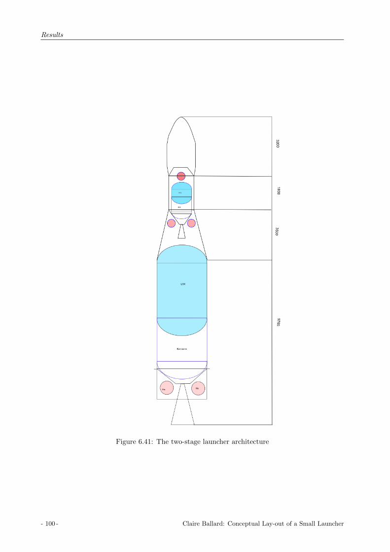
Results
Figure 6.41: The two-stage launcher architecture
- 100 - Claire Ballard: Conceptual Lay-out of a Small Launcher

Results
Figure 6.42: 3D drawing of the upper stage, 2-stage launcher
Figure 6.43: Section cut drawing of the upper stage, 2-stage launcher
Claire Ballard: Conceptual Lay-out of a Small Launcher - 101 -
Results
Attitude Control System). This system requires a hydrazine vessel with 38kg of hydrazine. Thisvessel has a diameter of 482mm and is placed in the middle of the avionics platform. The twothruster cluster modules of the RACS are diametrically opposite placed at the top of the stage.At the stage’s interstage structure, the common bulkhead NTO/MMH tank is attached thanksto the CTAR. The engine thrust frame is directly attached to the lower cylinder and the 22kNengine is attached to the ETF. The pressure control system is attached to the ETF as well asthe helium vessels. The helium vessel configuration is cylindrical with two spherical domes. Twohelium vessels with a diameter of 480mm are required. The interstage structure represents theconnection with the first stage, it is placed directly at the top of the first stage tank.The total length of the upper stage, including the cone and the interstage structure, is 5800mm.
Concerning the first stage with the Zenit booster, the common bulkhead as a load bearing propel-lant tank is chosen regarding the structural mass. The stage diameter is equal to 3000mm whichis the tank diameter as well. A skirt is placed below the tanks in order to protect the heliumvessels and other equipment as the pressure control system. This skirt length is equal to 1800mm.Two helium vessels are required; they have a cylindrical shape with two spherical domes. Thehelium vessel diameter is 400mm. The engine thrust frame is directly attached to the structureand enables connection to the Zenit engine.The total length of the stage is equal to 9765mm
The total length of the launcher including the fairing is 18265mm.
The mass breakdown
After the definition of the first and upper stage, the total mass of each stage has to be evalu-ated. The Structural Calculation Software Tool has enabled the calculation of the tank mass andthe main structural component masses, but there is still the need to evaluate the mass of theremaining equipment. Therefore, a mass breakdown has been established for both stages. Thedifferent subsystem masses have been chosen regarding existing studies and validated by an expert.
First stage mass breakdownThe following items have been considered in the mass break down:
• propulsion system
• equipped tanks (propellant tank, helium vessel)
• fluid masses ( helium, reserve propellant)
• structures (skirt)
• subsystems (thermal subsystems, neutralization system, electrical system)
The mass breakdown table is represented in Table 6.30. Only the main items presented before areincluding in this table. They are the relevant components for an upper-stage, the subsystems aredefined but not explained in detail.
• The mass of the Zenit engine is 1080kg.
• The calculated mass of the common bulkhead tank thanks to the Structural CalculationMass Tool is 805kg.
• The 900 liters of helium are stored in two vessels of 100kg each. This mass is evaluated byscaling existing vessels.
- 102 - Claire Ballard: Conceptual Lay-out of a Small Launcher
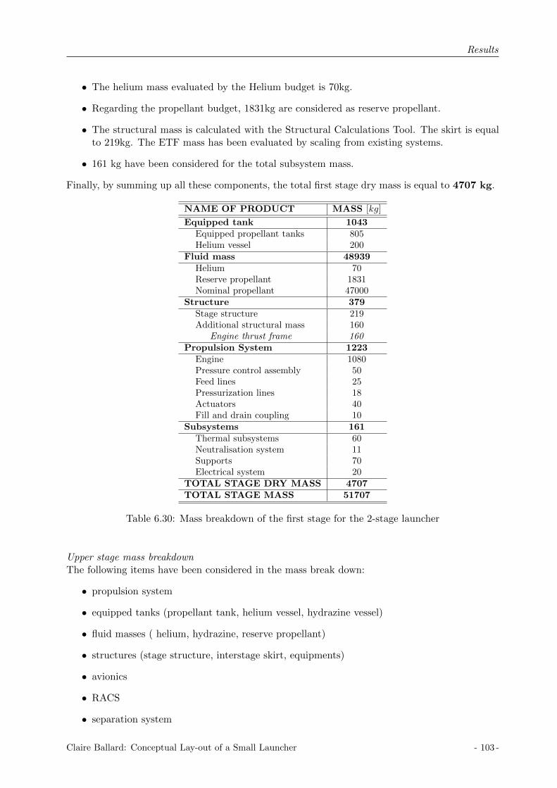
Results
• The helium mass evaluated by the Helium budget is 70kg.
• Regarding the propellant budget, 1831kg are considered as reserve propellant.
• The structural mass is calculated with the Structural Calculations Tool. The skirt is equalto 219kg. The ETF mass has been evaluated by scaling from existing systems.
• 161 kg have been considered for the total subsystem mass.
Finally, by summing up all these components, the total first stage dry mass is equal to 4707 kg.
NAME OF PRODUCT MASS [kg]
Equipped tank 1043Equipped propellant tanks 805Helium vessel 200
Fluid mass 48939Helium 70Reserve propellant 1831Nominal propellant 47000
Structure 379Stage structure 219Additional structural mass 160
Engine thrust frame 160Propulsion System 1223
Engine 1080Pressure control assembly 50Feed lines 25Pressurization lines 18Actuators 40Fill and drain coupling 10
Subsystems 161Thermal subsystems 60Neutralisation system 11Supports 70Electrical system 20
TOTAL STAGE DRY MASS 4707TOTAL STAGE MASS 51707
Table 6.30: Mass breakdown of the first stage for the 2-stage launcher
Upper stage mass breakdownThe following items have been considered in the mass break down:
• propulsion system
• equipped tanks (propellant tank, helium vessel, hydrazine vessel)
• fluid masses ( helium, hydrazine, reserve propellant)
• structures (stage structure, interstage skirt, equipments)
• avionics
• RACS
• separation system
Claire Ballard: Conceptual Lay-out of a Small Launcher - 103 -

Results
• subsystems (thermal subsystems, neutralization system, feed lines, electrical system)
The mass breakdown table is represented in Table 6.31. Only the main items presented before areincluded in this table. They are the relevant components for an upper-stage, the subsystems aredefined but not explained in detail.
• The mass of the 22kN thrust engine is 80kg.
• The calculated mass of the common bulkhead tank, thanks to the Structural CalculationMass Tool, is 142.2kg.
• The 200 liters of helium are stored in two vessels of 25kg each. This mass is evaluated byscaling existing vessels.
• The hydrazine vessel is the one used for the VEGA launcher, its mass is 8.45kg.
• The helium mass evaluated by the Helium budget is 12kg.
• The Hydrazine mass is the one considered for the VEGA launcher and it is 38kg.
• Regarding the propellant budget, 186kg are considered as reserve propellant.
• The structural mass is calculated with the Structural Calculations Tool. The stage structureis equal to 47.8kg and the interstage skirt is equal to 91.1kg. The upper cone, the avionicsplatform, the CTAR and the ETF masses have been evaluated by scaling from existingsystems.
• The avionic mass considered is the one of the VEGA launcher, 96kg.
• The RACS system is the one of the VEGA launcher. The total mass is 41.75kg.
• The separation system is evaluated by scaling from existing systems, 28kg.
• The subsystem masses are scaled regarding the VEGA launcher, 74 kg has been consideredfor the total subsystem mass.
Finally, by summing up all these components, the total upper stage dry mass is equal to 1071.2kg, with 119 kg of jettisonable mass.
6.4.7 Small launcher simulation
Simulations have been done with the complete launcher. The characteristics of the two stageshave been implemented in the MATLAB code. The propellant mass in the first stage has beenconsidered equal to 47000kg, and 2000kg in the upper stage, which are the required nominalpropellant masses. Regarding the mass breakdown, the structural mass is equal to 4707kg for thefirst stage and 952 for the upper stage. The interstage mass is equal to 119kg and the fairing massis equal to 180kg. The launcher characteristics are summarized in Table 6.32
With this launcher configuration, the MATLAB simulation shows that it is possible to place270kg of payload into the elliptical transfer orbit 200km perigee - 700km apogee. As there is aneed of ca. 35kg of propellant to realize the circularization, the payload which can be placed intothe circular orbit with a radius of 700km is around 235kg.
The simulation is represented in the following figures. Figure 6.44 shows the variation of thealtitude, velocity and flight path angle as functions of time and the altitude as a function ofvelocity, from the launch pad to the elliptical orbit. Each color corresponds to one stage:
- 104 - Claire Ballard: Conceptual Lay-out of a Small Launcher

Results
NAME OF PRODUCT JETTISONABLE MASS [kg]MASS [kg]
Equipped tank 200.2Equipped propellant tanks 142.2Helium vessel 50Hydrazine vessel 8
Fluid mass 2236Helium 12Hydrazine 38Reserve propellant 186Nominal propellant 2000
Structure 91.1 116.8Stage structure 47.8Interstage skirt 91.1Additional structural mass 114
Upper cone structure 45Avionics platform 22CTAR 14Engine thrust frame 33
Avionics 96RACS 41.75
Pressure transducers 0.5Pyrotechnic valves 1Feed line and drain valve 0.65Turbing kit 2Pipe support brackets + bolts 2.7Thruster cluster module 27Aerothermal cover 7.9
Separation system 28Pyrojacks 15.6Pyro lines 9.4RMV 3
Propulsion System 142.1Engine 80Pressure control assembly 15Feed lines 11Pressurization lines 9.4Passivation system 4.5Actuators 18Fill and drain coupling 4.2
Subsystems 74.3Thermal subsystems 22.7Neutralisation system 10Supports 26.5Electrical system/Hardware 15.1
TOTAL STAGE DRY MASS 119.1 952.15FAIRING 180TOTAL UPPER STAGE MASS 299.1 3202.15
Table 6.31: Mass breakdown of the upper stage for the 2-stage launcher
Claire Ballard: Conceptual Lay-out of a Small Launcher - 105 -

Results
Stage 1: Zenit Stage 2
Isp [s] 330 216Thrust [kN ] 849 22Propellant mass [kg] 47,000 2,000Dry mass [kg] 4,707 952Interstage mass [kg] 119Length [mm] 9,765 5,300Diameter [mm] 3,000 1,500
Table 6.32: The two stage launcher characteristics
0 200 400 6000
50
100
150
200Altitude vs Time
Time [s]
Altitu
de
[km
]
0 200 400 6000
2000
4000
6000
8000Speed vs Time
Time [s]
Ve
locity [
m/s
]
0 200 400 6000
20
40
60
80
100Angle vs Time
Time [s]
An
gle
[d
eg
]
0 2 4 6 80
50
100
150
200speed vs altitude
speed [km/s]
altitu
de
[km
]
Figure 6.44: 2-stage launcher simulation from launch pad to the elliptical orbit
• the blue curve is the first stage
• the red curve is the upper stage
Figure 6.45 represents the variation of altitude, velocity and flight path angle as functions of timeand the altitude as a function of velocity, from the launch pad to the circular orbit. Each colorcorresponds to a certain part of the trajectory:
• the blue curve is from the launch pad to the elliptical orbit at burnout of the upper stage
• the red curve corresponds to the trajectory in orbit when the thrust is equal to zero
• the green curve corresponds to the trajectory in the circular orbit
The upper stage re-ignition happens when the spacecraft reaches the orbit apogee. Figure 6.46represents the variation of mass, thrust, dynamic pressure, lateral and longitudinal velocity asfunctions of time. The lateral velocity is the red curve and the longitudinal velocity is the blueone.
- 106 - Claire Ballard: Conceptual Lay-out of a Small Launcher
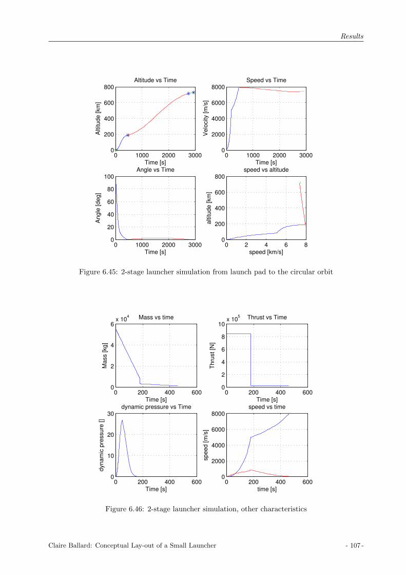
Results
0 1000 2000 30000
200
400
600
800Altitude vs Time
Time [s]
Altitu
de
[km
]
0 1000 2000 30000
2000
4000
6000
8000Speed vs Time
Time [s]
Ve
locity [
m/s
]
0 1000 2000 30000
20
40
60
80
100Angle vs Time
Time [s]
An
gle
[d
eg
]
0 2 4 6 80
200
400
600
800speed vs altitude
speed [km/s]
altitu
de
[km
]
Figure 6.45: 2-stage launcher simulation from launch pad to the circular orbit
0 200 400 6000
2
4
6x 10
4 Mass vs time
Time [s]
Ma
ss [
kg
]
0 200 400 6000
2
4
6
8
10x 10
5 Thrust vs Time
Time [s]
Th
rust
[N]
0 200 400 6000
10
20
30dynamic pressure vs Time
Time [s]
dyn
am
ic p
ressu
re [
]
0 200 400 6000
2000
4000
6000
8000speed vs time
time [s]
sp
ee
d [
m/s
]
Figure 6.46: 2-stage launcher simulation, other characteristics
Claire Ballard: Conceptual Lay-out of a Small Launcher - 107 -

Results
- 108 - Claire Ballard: Conceptual Lay-out of a Small Launcher

Conclusion
Chapter 7
Conclusion
The purpose of this Master Thesis was to perform the conceptual lay-out of a small launcher.The small launcher has to be able to place into orbit 250kg of payload in a circular orbit with aradius of 700km and an inclination of 90 degrees. In order to reduce development costs, the smalllauncher must use existing stages for the first and/or second stage, whereas the upper stage isentirely designed using an engine under investigation at the company.This preliminary study included two different aspects: one aspect concerning the launcher per-formance and the other one concerning the stage design. The launcher performance needed to bestudied in order to define the launcher characteristics and to know exactly the amount of payloadthat the small launcher can carry and place into orbit. A complete new tool has been developedto study the launcher performance. This tool is coded using MATLAB. By setting the launchercharacteristics, the tool enables simulation of rocket trajectories. Based on the Nelder-Mead algo-rithm, the tool sizes, as well as to optimize, the launcher staging and the gravity turn trajectory.The study concerning the stage design is based on a previous tool written in Excel. This toolhas been changed and improved in the purpose of this study. It enables the evaluation of thepropellant budget, helium budget and structural mass calculations.Two small launchers have been highlighted from the study: a two-stage launcher using two liquidstages, and a three-stage launcher using two solid stages and a liquid upper stage. After researchon existing launchers and preliminary design of the upper stage, the performance tool has beenused to choose the different characteristics of the launchers. The purpose was to choose the exist-ing stages which give the best performances and to define the upper stage characteristics. Then,the upper stage for each launcher has been designed in details.
Concerning the three-stage small launcher, research has been done on existing stages using solidpropulsion focusing only on boosters with not too high thrust, as the purpose was to define asmall launcher. From the research, correlations have been settled between the thrust, specificimpulse, structural index and propellant mass in the stages. The launcher characteristics are sodefined thanks to its propellant mass. A first rough design has been done for the upper stagein order to get the variations of the structural index as a function of the engine thrust and theamount of propellant which are the two variables which needed to be chosen in the purpose of thisstudy. The specific impulse of the upper stage has always been considered constant as the engineunder investigation at the company has the same specific impulse. By using the performance toolwith these curves directly implemented in the code, an optimum launcher could be found. Thevariables were the amount of propellant in the three stages, the thrust in the upper stage and thegravity turn parameters. So, by setting the launcher characteristics and using the optimizationprogram, the purpose was to find the optimum launcher characteristics. From these simulationsit has been seen a tendency about the amount of propellant in the different stages, and from thistendency existing stages have been chosen to be study in more detail. The chosen existing stages
Claire Ballard: Conceptual Lay-out of a Small Launcher - 109 -

Conclusion
are the Italian boosters, Zefiro 23 and Zefiro 9, and the brazilian boosters, S-50 and S-43. Bysetting these launcher characteristics, simulations have been done in order to find the upper stagecharacteristics which give the best performances. The variables were so the propellant mass andthrust in the upper stage and the gravity turn parameters. Then, the launcher which gives thebest performances has been chosen and the upper stage has been designed in detail. The chosensmall launcher uses the Zefiro 23 as a first stage, the Zefiro 9 as a second stage and an upper stagewith a 3kN thrust engine and 500kg of propellant mass.Then, the upper stage has been designed in detail. In order to perform the design study, func-tional budget concerning the propellant, the pressure gas and the structure have been prepared byusing and improving an existing excel tool. From the propellant budget, 603 kg of propellant arerequired, which corresponds to a volume of 0.7m3. From the helium budget, 70 liters of helium areneeded, pressurized at 340 bars. Three tank configurations have been studied and the commonbulkhead as non load bearing propellant tank has been chosen regarding the structural mass, andaccording to expert’s advices, the direct access between the lower and upper part of the stage.From structural calculations, the propellant tank mass is equal to 53.5 kg, the helium vessel to15kg and the structure mass to 155.5kg. Then, considering all the important equipments neededin an upper stage, namely the attitude control system, the pressurization system, the avionics,the separation system and the subsystems, a total dry mass of around 710kg is calculated in atotal mass breakdown.Finally, using the performance tool, a final performance assessment has been done on the three-stage launcher. This configuration enables to place into the circular orbit of 700km radius, apayload of 295kg which fulfill all the preset requirements.This launcher uses the two Italian boosters Zefiro 23 and Zefiro 9 which have been developedfor the VEGA launcher. This study has not taken into account any changes on these boosterswhich would necessarily be required for the development of the small launcher. Furthermore, theBrazil is currently developing boosters. So far, this study shows the Italian boosters give betterresults than the brazilian boosters but, the Italians profit from the european aerospace knowledge.Therefore, in the future, the Brazil might be able to develop boosters which will have better per-formances and will be more competitive regarding certainly the production costs.
Concerning the two-stage launcher, research has been done on existing stages using liquid propul-sion focusing on stages with not too high thrust as well. From the research and preliminary sim-ulations, it has been noticed that the existing stages using liquid propulsion with thrust enoughto lift-off from Earth were too big for the purpose of this study. So, it has been decided to modifythe existing liquid stages. Three existing stages have been studied: the Soyuz first stage, the Zenitsecond stage and the Zenit new booster which is an engine derived from the Zenit second stageengine. The stage modification was on the amount of propellant and so on the structure as well.From the research, the correlation between the structural index and the propellant mass has beenfound. But, the structural index calculation does not take into account the engine mass. Indeed,as the changes are only done on the amount of propellant, the engine is kept and so its character-istics, thrust and specific impulse, and mass as well. By using the performance tool, the purposewas to find both the amount of propellant in the first stage and the upper stage characteristicswhich give the best performances. The variables were the amount of propellant in the two stages,the thrust in the upper stage and the gravity turn parameters. From these simulations, the newZenit booster engine has been chosen regarding its performances. The chosen two-stage launcheruses the new Zenit booster as a first stage with 47000kg of propellant, and an upper stage with22kN thrust and 2000kg of propellant mass.Then, the first stage and the upper stage have been designed in detail. The design study has beenperformed using the existing excel tool in order to get the functional budgets. About the upperstage, from the propellant budget, 2186kg of propellant are required, which correspond to a volume
- 110 - Claire Ballard: Conceptual Lay-out of a Small Launcher

Conclusion
of 2.1m3. From the helium budget, 200 liters of helium are needed, pressurized at 360bars. Thecommon bulkhead as non load bearing propellant tank configuration has been chosen regardingthe structural mass, and according expert’s advices, the direct access between the lower and upperpart of the stage. From structural calculations, the propellant tank mass is equal to 142.2kg, thehelium vessel to 50kg and the structural mass to 253kg. Then, considering the equipments neededin an upper stage, a total dry mass of 1065kg is calculated in a total mass breakdown. The samestudy has been done for the first stage. From the propellant budget, 48831kg of propellant arerequired, which correspond to 51m3. From the helium budget, 900 liters of helium are needed,pressurized at 376bars. The common bulkhead as load bearing propellant tank configuration hasbeen chosen regarding the structural mass. From structural calculations, the propellant tank massis equal to 805kg, the helium vessel to 200kg and the structural mass to 379kg. Then consideringthe equipments, a total dry mass of 4707kg is calculated in a total mass breakdown.Finally, using the performance tool, a final performance assessment has been done on the two-stagelauncher. This configuration enables to place into the circular orbit of 700km radius, a payloadof 235kg, which fulfill all the preset requirements.This launcher uses the new Zenit booster which is still under investigation. This engine is derivedfrom the engine used in the Zenit second stage. It has been chosen because the development of thisnew engine is done in the purpose to be used in a first stage. So, this engine fill the requirementsof this launcher, and as its development is done in order to be used in a first stage launcher nochange would be needed on it for the future development of the small launcher. Only the stagestructure needs to be designed.
Further development can be executed on the basis of this thesis. First, the developed perfor-mance tool is a simple tool which enables fast rocket trajectory simulations. It is based on severalassumptions in order to have a simple tool but some of the assumptions can be evaluated again.For instance, a study focused on the gravity turn trajectory would enables to have a better un-derstanding of rocket trajectory optimization. Furthermore, the Nelder-Mead algorithm has beenchosen regarding its simplicity to be understandable and its quick implementation in the code,but it may not be the best control theory algorithm. Now, as the characteristics of two smalllaunchers have been identified, technology development can be initiated. More detailed designand performance calculations can be started.
As a conclusion for this study, two small launchers have been identified using existing technologies:a three-stage launcher using the Zefiro 23 and Zefiro 9 as first and second stages and a 3kN thrustupper stage, a two-stage launcher using the under-investigation Zenit engine in the first stage anda 22kN thrust upper stage. Both launchers enable to place into a circular orbit with a radius of700km a payload of nearly 300kg for the three-stage configuration and 235kg for the two-stageconfiguration.
Claire Ballard: Conceptual Lay-out of a Small Launcher - 111 -

Conclusion
- 112 - Claire Ballard: Conceptual Lay-out of a Small Launcher

Bibliography
Bibliography
[1] George P.Sutton, Oscar Biblarz, Rocket propulsion elements. Wiley, 8th Edition, 2010, chap-ter ”Flight performance”.
[2] http://www.astronautix.com
[3] Carina Ludwig, Conceptual lay-out of a departure stage used on the A5ME upper stage usingsystems engineering tools. Diplomarbeit, 2010.
[4] www.scholarpedia.org/article/Nelder-Mead-algorithm
[5] Ronald W. Humble, Gary N. Henry, Wiley J.larson, Space propulsion analysis and design,Space technology series.
[6] William E. Wiesel, Spaceflight dynamics, second edition.
[7] Ludwig Marian Celnikier, Basics of space flight, Edition Frontires, 1993
[8] Arianespace, Ariane 5 user’s manual, Ise. 5 Rev. 1, www.arianespace.com
[9] Arianespace, VEGA user’s manual, www.arianespace.com
[10] Input data package provided by Astrium, Launcher Pre-Design VENUS
[11] Input data package provided by Astrium, VEGA programme, AVUM structures plus inter-stage 3/AVUM,
[12] Input data package provided by Astrium, Mass budget report for A5ME upper stage,
[13] Input data package provided by Astrium, Synthesis of budgets for RPS,
[14] DLR DATA Package, VEGA propulsion
[15] Input data package provided by Astrium, Trajectoires de reference
[16] DLR final presentation, CE 2 study results, CEF study - VENUS II - 4 stages 26.02.2010
[17] Venus performance study, AESTUS II Engine Characteristics
[18] NASA SP-8007, Buckling of thin-walled circular cylinders, NASA, Rev. 1, August 1965
[19] NASA SP-8032, Buckling of thin-walled doubly curved shells, NASA, August 1969
[20] Input data package provided by Astrium, RACS
[21] Sea Launch, Land Launch User’s Guide, 28.07.2004
[22] www.yuzhnoye.com
[23] Input data package provided by Astrium, VEGA program, AVUM-LPS
Claire Ballard: Conceptual Lay-out of a Small Launcher - 113 -
Bibliography
[24] Input data package provided by Astrium, Mass estimation for VENUS
[25] Input data package provided by Astrium, VEGA programme, payload adapter
[26] User’s manual, Performance tool, February 2012
- 114 - Claire Ballard: Conceptual Lay-out of a Small Launcher

Thrust profile
Appendix A
Thrust profile
A.1 VEGA boosters thrust profile
0 20 40 60 80 100 1200
500
1000
1500
2000
2500
3000
3500Thrust vs Time
Time [s]
Thru
st [k
N]
(a) P80 thrust profile
0 10 20 30 40 50 60 70 80 900
200
400
600
800
1000
1200Thrust vs Time
Time [s]
Thru
st [k
N]
(b) Z23 thrust profile
0 20 40 60 80 100 1200
50
100
150
200
250
300
350Thrust vs Time
Time [s]
Thru
st [k
N]
(c) Z9 thrust profile
Figure A.1: Thrust profile of the different VEGA launcher boosters
Claire Ballard: Conceptual Lay-out of a Small Launcher - 115 -

Thrust profile
A.2 Ariane 5 boosters thrust profile
0 20 40 60 80 100 120 1400
5000
10000
15000Thrust profile
time [s]
thru
st
[kN
]
Figure A.2: Thrust profile of the solid booster
- 116 - Claire Ballard: Conceptual Lay-out of a Small Launcher

Functional Budget Calculation Tool
Appendix B
Functional Budget Calculation Tool
Figure B.1: Propellant budget excel sheet
Figure B.2: Tank volume excel sheet
Claire Ballard: Conceptual Lay-out of a Small Launcher - 117 -

Functional Budget Calculation Tool
Figure B.3: Pressure budget excel sheet
Figure B.4: Helium pressure excel sheet
- 118 - Claire Ballard: Conceptual Lay-out of a Small Launcher

MATLAB function files
Appendix C
MATLAB function files
Figure C.1: Atmospheric model function
Figure C.2: Mass function
Claire Ballard: Conceptual Lay-out of a Small Launcher - 119 -

MATLAB function files
Figure C.3: Local gravity function
Figure C.4: Reference area function
- 120 - Claire Ballard: Conceptual Lay-out of a Small Launcher
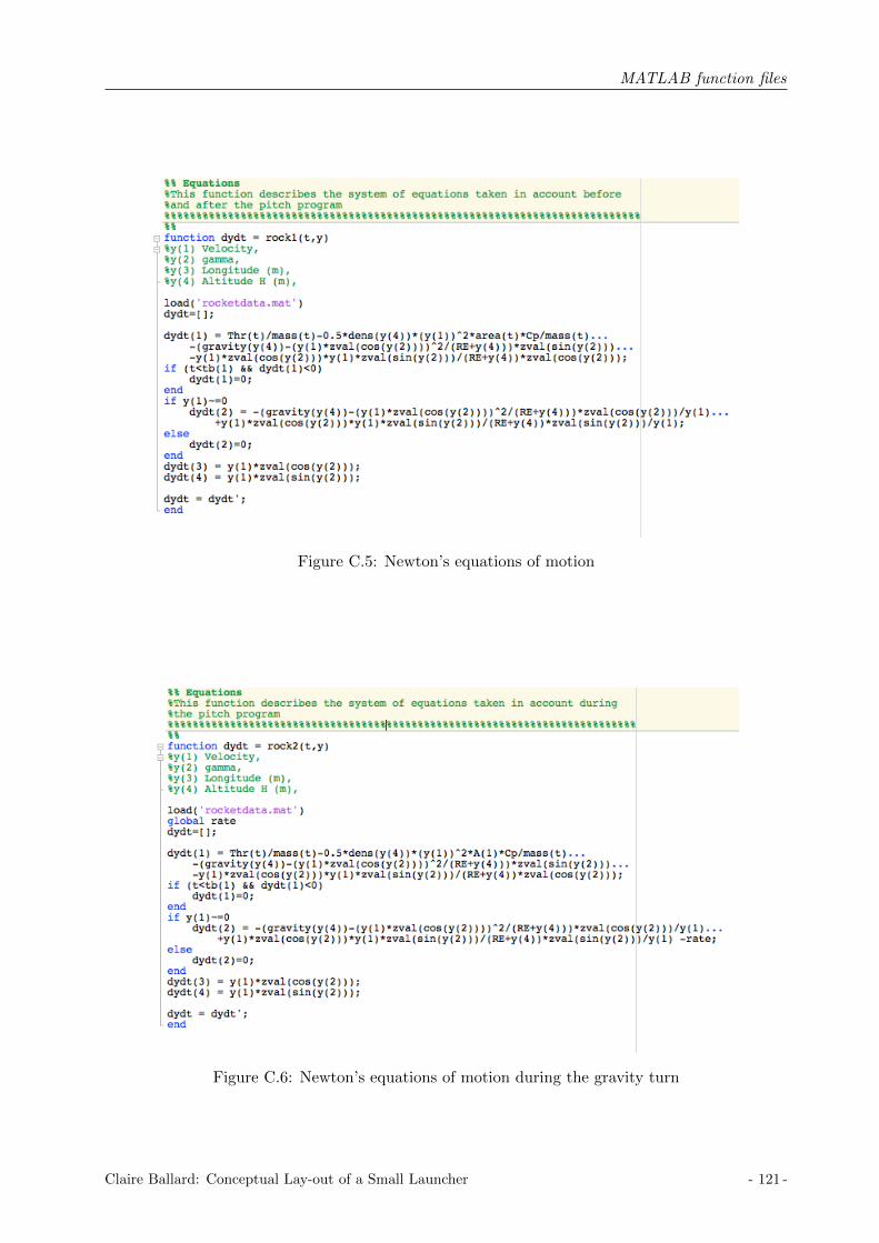
MATLAB function files
Figure C.5: Newton’s equations of motion
Figure C.6: Newton’s equations of motion during the gravity turn
Claire Ballard: Conceptual Lay-out of a Small Launcher - 121 -

MATLAB function files
- 122 - Claire Ballard: Conceptual Lay-out of a Small Launcher
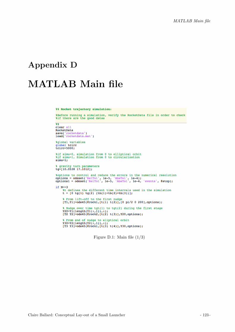
MATLAB Main file
Appendix D
MATLAB Main file
Figure D.1: Main file (1/3)
Claire Ballard: Conceptual Lay-out of a Small Launcher - 123 -
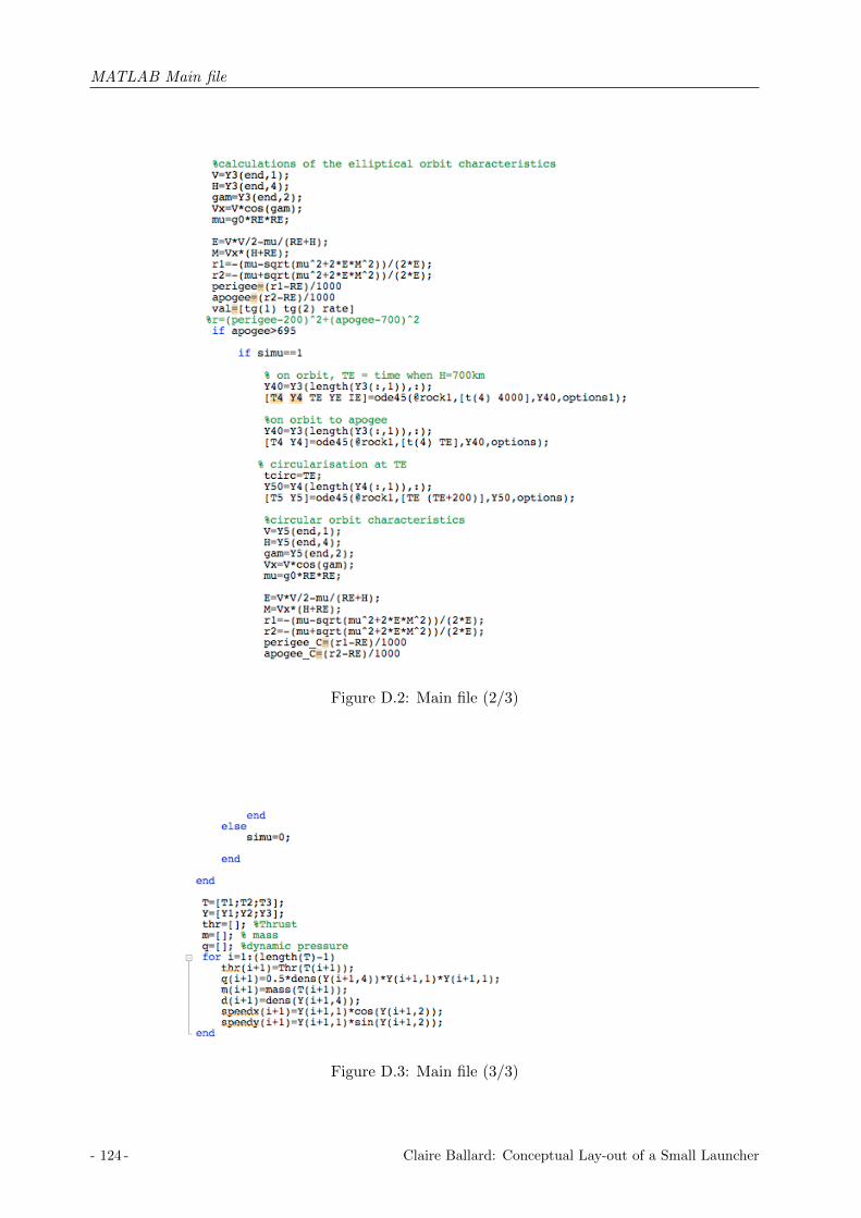
MATLAB Main file
Figure D.2: Main file (2/3)
Figure D.3: Main file (3/3)
- 124 - Claire Ballard: Conceptual Lay-out of a Small Launcher

Fluid schematic
Appendix E
Fluid schematic
BDVM burst disk passivation MMHBDVN burst disk passivation NTOBDM burst disk MMHBDN burst disk NTOBM branching manifold with filterCRVH fill and drain valve HeliumCRVM fill and drain valve MMHCRVN fill and drain valve NTOCVM check valve MMHCVN check valve NTOETF engine thrust frameFCV flow control valveFDV1 pressurant fill and drain valveFDV2 propellant fill and drain valveFDV3 feedline fill and drain valveFH helium filterHVO Helium Venting OrificeISPR I stage pressure regulatorIISPR II stage pressure regulatorLVM Latch valve MMHLVN Latch valve NTOMEOP maximum expected operating pressurePO priming orificePT redundant pressure transducersPV1 priming pyrovalvePV2 mainflow pyrovalvePV3 depletion pressure transducersPVAM pressure valve assembly (MMH)PVAN pressure valve assembly (NTO)PVH pyrovalve HeliumPVM pyrovalve MMHPVN pyrovalve NTORDCM vent valve MMHRDCN vent valve NTOTCA thrust chamber assemblyTCM thruster cluster moduleTH helium tankTM MMH tank
Claire Ballard: Conceptual Lay-out of a Small Launcher - 125 -

Fluid schematic
Figure E.1: Upper stage fluid schematic
- 126 - Claire Ballard: Conceptual Lay-out of a Small Launcher

Technical drawings
Appendix F
Technical drawings
Claire Ballard: Conceptual Lay-out of a Small Launcher - 127 -

Technical drawings
Figure F.1: Upper stage technical drawing, 3-stage launcher
- 128 - Claire Ballard: Conceptual Lay-out of a Small Launcher

Technical drawings
Figure F.2: Upper stage technical drawing 1, 2-stage launcher
Claire Ballard: Conceptual Lay-out of a Small Launcher - 129 -

Technical drawings
Figure F.3: Upper stage technical drawing 2, 2-stage launcher
- 130 - Claire Ballard: Conceptual Lay-out of a Small Launcher