mast-r-fence iii
TRANSCRIPT
1
MAST-R-FENCE IIIOwners Manual Model #04400
61 Forest Plain Road Oro-Medonte, Ontario, Canada L3V 0R4 Toll Free: 1-800-436-6799 Local: 705-726-8233 Fax: 705-327-0295 Email: [email protected] Web: www.jessem.com

2
JESSEM TOOL COMPANY - LIMITED WARRANTY WARRANTY LIMITATIONS
MESSAGE TO OUR CUSTOMERS
CONTINUOUS PRODUCT IMPROVEMENT POLICY
All JessEm products are warranted to be free from defects in material and workmanship. JessEm will repair or replace any product which upon inspection, proves to be defective for a period of (1) year from dated receipt and proof of purchase from an autho-rized JessEm Distributor. All warranty claims should be made direct to JessEm Tool Company.
This warranty does not cover:
• Repairs or alterations made or attempted by anyone other than JessEm Tool Company or an authorized
JessEm service professional.• Normal wear and tear.• Abuse, misuse or neglect.
Contact JessEm for a warranty claim return autho-rization and instructions to proceed. The consumer is responsible for shipping costs to return product to JessEm Tool Company. We will repair or replace the product at our discretion and JessEm Tool will return shipment to you at no charge.
• Improper care or maintenance.• Continued use after partial failure.• Products that have been modified in any way.• Products used with improper accessories
Thank you for choosing the Mast-R-Fence III router table fence Model: #04400 from JessEm Tool Company. We appreciate your support and hope that our product serves you well. This product is designed to provide many years of reliable service, provided it is used as intended and taken care of.
IMPORTANTRead and understand the contents of
this manual before assembly oroperation of this product
This user manual will assist you in assembly and general operation of this product. It is not our intent to teach you about woodworking. It is assumed that you are an experienced woodworker with the basic skills and experience necessary to use this product safely. If after reading the following instructions, you are un-sure or uncomfortable about safely using this product, we urge you to seek additional information through widely available woodworking books or classes.
As part of our Continuous Product Improvement Policy, JessEm products are always advancing in design, quality and function. Therefore, there may be differences between what is shown in our catalogs, on our website, on retail displays and what is sold at time of purchase. We reserve the right to make positive changes to our products at our discretion to ensure you, the customer, have the very best product.
State of California: WARNING Cancer and Reproductive Harm.
www.P65Warnings.ca.gov
!
!
3
IMPORTANT SAFETY PRECAUTIONS
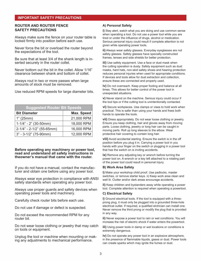
ROUTER AND ROUTER FENCESAFETY PRECAUTIONS
Always make sure the fence on your router table islocked firmly into position before each use.
Never force the bit or overload the router beyondthe expectations of the tool.
Be sure that at least 3/4 of the shank length is in-serted securely in the router collet.
Never bottom out the bit in the collet. Allow 1/16”clearance between shank and bottom of collet.
Always rout in two or more passes when largeamounts of stock must be removed.
Use reduced RPM speeds for large diameter bits.
Before operating any machinery or power tool,read and understand all safety instructions in theowner’s manual that came with the router.
If you do not have a manual, contact the manufac-turer and obtain one before using any power tool.
Always wear eye protection in compliance with ANSI safety standards when operating any power tool.
Always use proper guards and safety devices when operating power tools and machinery.
Carefully check router bits before each use.
Do not use if damage or defect is suspected.
Do not exceed the recommended RPM for any router bit.
Do not wear loose clothing or jewelry that may catch on tools or equipment.
Unplug the tool or machine when mounting or mak-ing any adjustments to mechanical performance.
A) Personal Safetyi) Stay alert, watch what you are doing and use common sense when operating a tool. Do not use a power tool while you are tired or under the influence of drugs, alcohol or medication. Serious personal injury could result if complete attention is not given while operating power tools.
ii) Always wear safety glasses. Everyday eyeglasses are not safety glasses. Safety glasses have specially constructed frames, lenses and side shields for better protection.
iii) Use safety equipment. Use a face or dust mask when the cutting operation is dusty. Safety equipment such as dust masks, hard hats, non-skid safety shoes and hearing protection reduces personal injuries when used for appropriate conditions. If devices and tools allow for dust extraction and collection, ensure these are connected and properly used.
iv) Do not overreach. Keep proper footing and balance at all times. This allows for better control of the power tool inunexpected situations.
v) Never stand on the machine. Serious injury could occur ifthe tool tips or if the cutting tool is unintentionally contacted.
vi) Secure workpieces. Use clamps or vises to hold work when practical. This is safer than using your hands and frees both hands to operate the tools.
vii) Dress appropriately. Do not wear loose clothing or jewelry. Ensure you keep clothing, hair and gloves away from moving parts. Loose clothing, jewelry or long hair can be caught in moving parts. Roll up long sleeves to the elbow. Wear protective hair covering to contain long hair.
viii) Avoid accidental starting. Ensure the switch is in the off position before you plug it in. Carrying a power tool in you hands with your finger on the switch or plugging in a power tool that has the switch on is inviting accidents.
ix) Remove any adjusting key or wrench before turning the power tool on. A wrench or a key left attached to a rotating part of the power tool could result in personal injury.
B) Work Area Safetyi) Make your workshop child proof. Use padlocks, master switches, or remove starter keys. ii) Keep work area clean and well lit. Clutter and/or dark areas encourage accidents.
ii) Keep children and bystanders away while operating a power tool. Complete attention is required when operating a powertool.
C) Electrical Safetyi) Ground electrical tools. If the tool is equipped with a three-prong plug, it must only be plugged into a grounded three-hole electrical outlet. If required, a qualified elctrician can install one. Never remove the third prong or modify the plug that is provided in any way.
ii) Never expose a power tool to rain or wet conditions. You will increase the risk of electric shock if water enters the powertool.
iii) Using power tools in damp or wet locations or conditions is extremely dangerous.
iv) Do not operate any power tool in an explosive atmosphere, in the presence of flammable liquids, gases or dust. Power tools can create sparks which may ignite the fumes or dust.
Suggested Router Bit SpeedsBit Diameter Max. Speed1” (25mm) 21,000 RPM1-1/4” - 2” (30-50mm) 18,000 RPM2-1/4” - 2-1/2” (55-65mm) 16,000 RPM3” - 3-1/2” (75-90mm) 12,000 RPM
4
1 2
8 9
10
20 18
19
28
33
36
4
5
2329
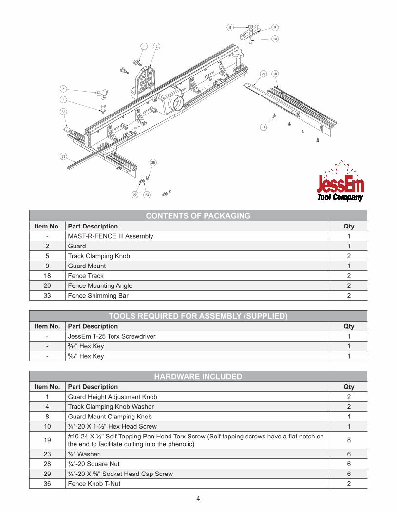
CONTENTS OF PACKAGINGItem No. Part Description Qty
- MAST-R-FENCE III Assembly 12 Guard 15 Track Clamping Knob 29 Guard Mount 1
18 Fence Track 220 Fence Mounting Angle 233 Fence Shimming Bar 2
TOOLS REQUIRED FOR ASSEMBLY (SUPPLIED)Item No. Part Description Qty
- JessEm T-25 Torx Screwdriver 1- 3⁄16" Hex Key 1- 5⁄64" Hex Key 1
HARDWARE INCLUDEDItem No. Part Description Qty
1 Guard Height Adjustment Knob 24 Track Clamping Knob Washer 28 Guard Mount Clamping Knob 1
10 ¼"-20 X 1-½" Hex Head Screw 1
19 #10-24 X ½" Self Tapping Pan Head Torx Screw (Self tapping screws have a flat notch on the end to facilitate cutting into the phenolic) 8
23 ¼" Washer 628 ¼"-20 Square Nut 629 ¼"-20 X 5⁄8" Socket Head Cap Screw 636 Fence Knob T-Nut 2
5
THE FOLLOWING INSTRUCTIONS ARE FOR MOUNTING THE #04400 MAST-R-FENCE III TO A JESSEM MAST-R-TOP OR A JESSEM MAST-R-LIFT EXCEL II TOP
THE FOLLOWING INSTRUCTIONS ARE FOR MOUNTING THE #04400 MAST-R-FENCE III TO A NON-JESSEM TOP
NOTE: If you are mounting your Mast-R-Fence III to a Non-JessEm top, please skip to step 2.
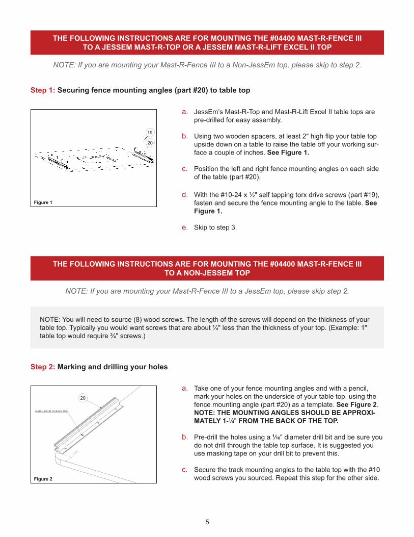
Step 1: Securing fence mounting angles (part #20) to table top
a. JessEm’s Mast-R-Top and Mast-R-Lift Excel II table tops are pre-drilled for easy assembly.
b. Using two wooden spacers, at least 2" high flip your table top upside down on a table to raise the table off your working sur-face a couple of inches. See Figure 1.
c. Position the left and right fence mounting angles on each side of the table (part #20).
d. With the #10-24 x ½" self tapping torx drive screws (part #19), fasten and secure the fence mounting angle to the table. See Figure 1.
e. Skip to step 3.
Figure 1
Step 2: Marking and drilling your holes
a. Take one of your fence mounting angles and with a pencil, mark your holes on the underside of your table top, using the fence mounting angle (part #20) as a template. See Figure 2. NOTE: THE MOUNTING ANGLES SHOULD BE APPROXI-MATELY 1-1⁄4" FROM THE BACK OF THE TOP.
b. Pre-drill the holes using a 1⁄16" diameter drill bit and be sure you do not drill through the table top surface. It is suggested you use masking tape on your drill bit to prevent this.
c. Secure the track mounting angles to the table top with the #10 wood screws you sourced. Repeat this step for the other side.
1-1/4"
MARK 4 HOLES ON EACH SIDE
20
Figure 2
NOTE: You will need to source (8) wood screws. The length of the screws will depend on the thickness of your table top. Typically you would want screws that are about ¼" less than the thickness of your top. (Example: 1" table top would require ¾" screws.)
NOTE: If you are mounting your Mast-R-Fence III to a JessEm top, please skip step 2.
19
20
20
6
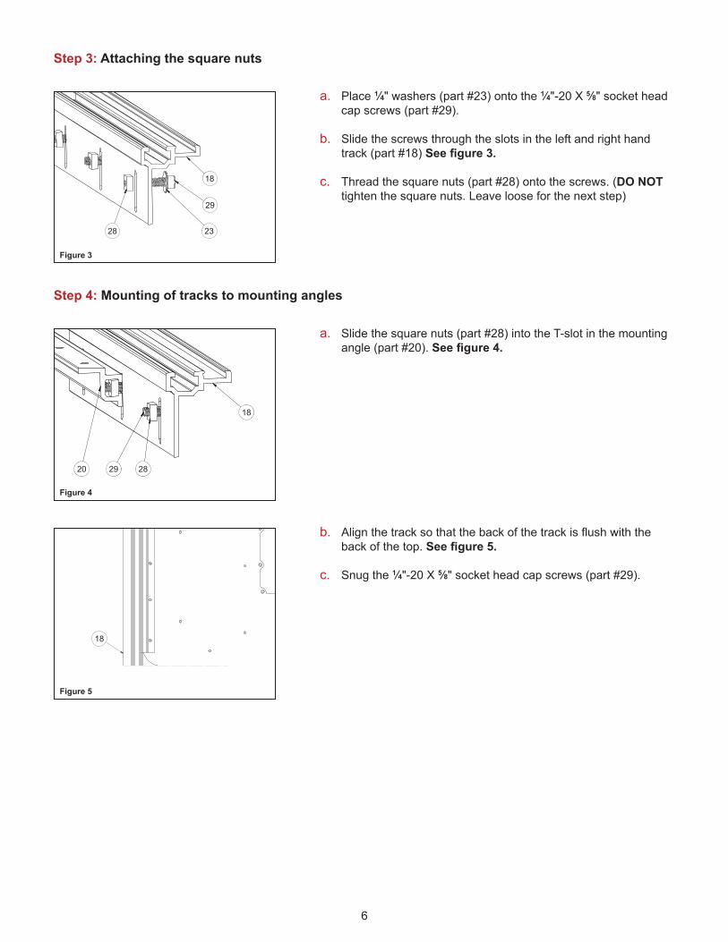
Step 4: Mounting of tracks to mounting angles
a. Place 1⁄4" washers (part #23) onto the 1⁄4"-20 X 5⁄8" socket head cap screws (part #29).
b. Slide the screws through the slots in the left and right hand track (part #18) See figure 3.
c. Thread the square nuts (part #28) onto the screws. (DO NOT tighten the square nuts. Leave loose for the next step)
a. Slide the square nuts (part #28) into the T-slot in the mounting angle (part #20). See figure 4.
b. Align the track so that the back of the track is flush with the back of the top. See figure 5.
c. Snug the 1⁄4"-20 X 5⁄8" socket head cap screws (part #29).
29
23
18
28
Figure 3
18
282920
Figure 4
18
Figure 5
Step 3: Attaching the square nuts
18
29
2328
18
282920
18
7
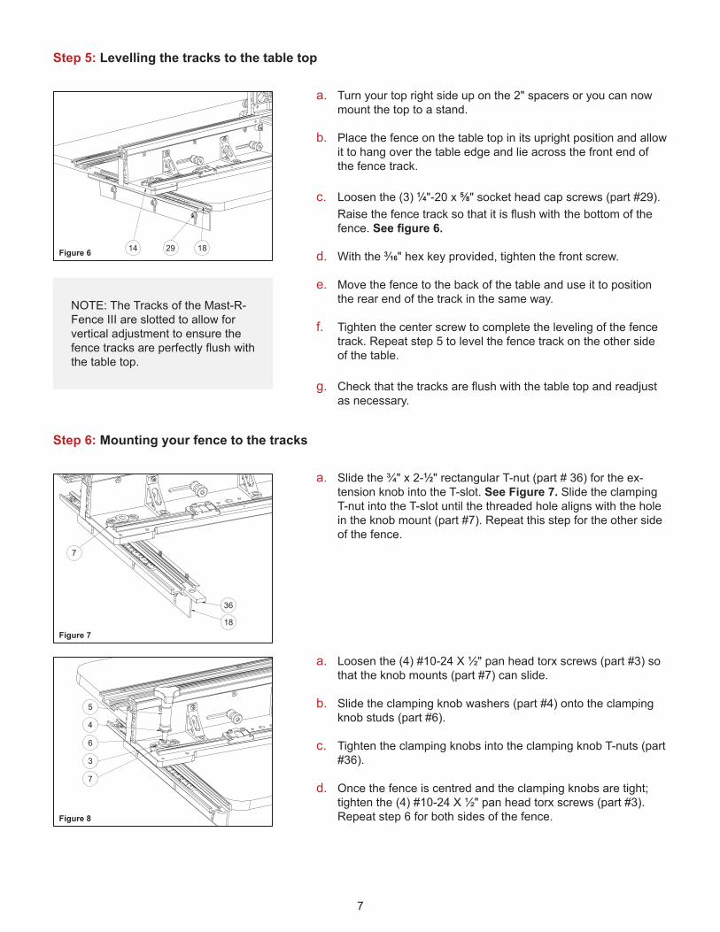
Step 6: Mounting your fence to the tracks
a. Slide the ¾" x 2-1⁄2" rectangular T-nut (part # 36) for the ex-tension knob into the T-slot. See Figure 7. Slide the clamping T-nut into the T-slot until the threaded hole aligns with the hole in the knob mount (part #7). Repeat this step for the other side of the fence.
a. Loosen the (4) #10-24 X ½" pan head torx screws (part #3) so that the knob mounts (part #7) can slide.
b. Slide the clamping knob washers (part #4) onto the clamping knob studs (part #6).
c. Tighten the clamping knobs into the clamping knob T-nuts (part #36).
d. Once the fence is centred and the clamping knobs are tight; tighten the (4) #10-24 X ½" pan head torx screws (part #3). Repeat step 6 for both sides of the fence.
36
18
7
Figure 7
5
4
6
3
7
Figure 8
Step 5: Levelling the tracks to the table top
a. Turn your top right side up on the 2" spacers or you can now mount the top to a stand.
b. Place the fence on the table top in its upright position and allow it to hang over the table edge and lie across the front end of the fence track.
c. Loosen the (3) 1⁄4"-20 x 5⁄8" socket head cap screws (part #29). Raise the fence track so that it is flush with the bottom of the fence. See figure 6.
d. With the 3⁄16" hex key provided, tighten the front screw.
e. Move the fence to the back of the table and use it to position the rear end of the track in the same way.
f. Tighten the center screw to complete the leveling of the fence track. Repeat step 5 to level the fence track on the other side of the table.
g. Check that the tracks are flush with the table top and readjust as necessary.
NOTE: The Tracks of the Mast-R-Fence III are slotted to allow for vertical adjustment to ensure the fence tracks are perfectly flush with the table top.
14 29 18Figure 6 182914
18
36
7
5
4
6
3
7
8
MOUNTING THE MAST-R-FENCE III TO EMBEDDED TABLE TOP TRACKS
SETTING FENCE SCALES
NOTE: You will need to source a T-nut or hex nut with a 3⁄8"-16 thread which matches the width of the T-slot in your top.
NOTE: If you are mounting your Mast-R-Fence III with the provided tracks, please skip step 7.
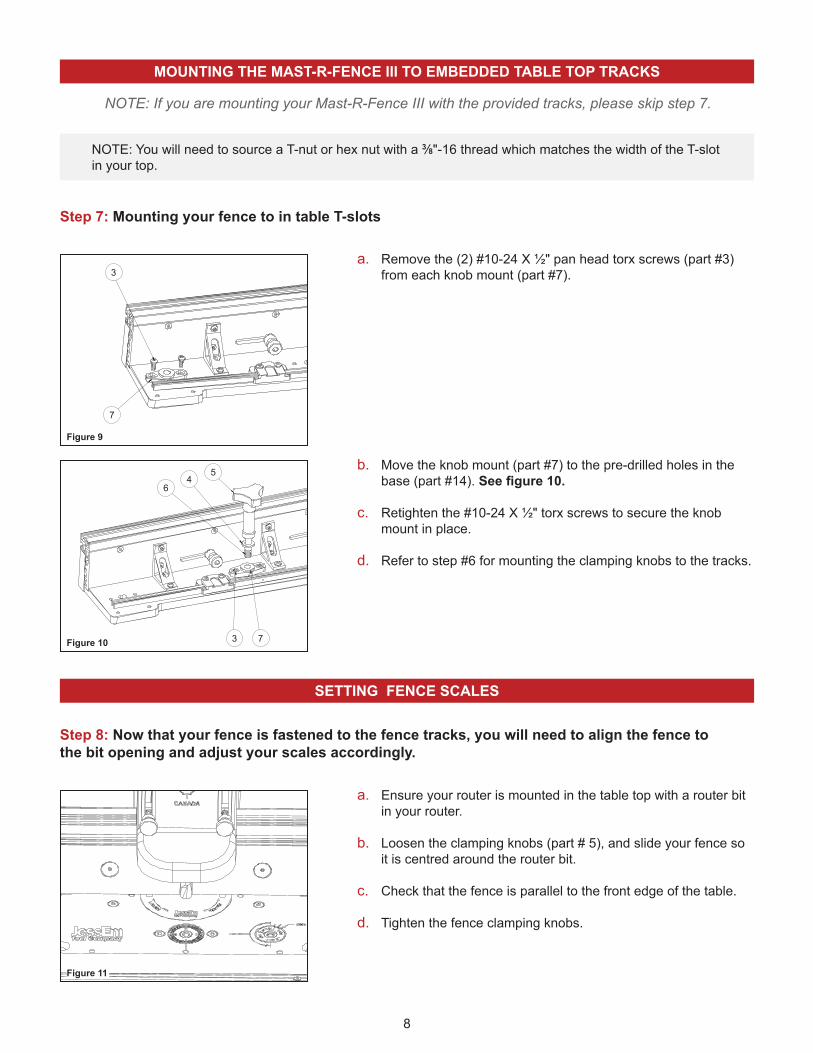
Step 8: Now that your fence is fastened to the fence tracks, you will need to align the fence tothe bit opening and adjust your scales accordingly.
a. Ensure your router is mounted in the table top with a router bit in your router.
b. Loosen the clamping knobs (part # 5), and slide your fence so it is centred around the router bit.
c. Check that the fence is parallel to the front edge of the table.
d. Tighten the fence clamping knobs.
Figure 11
Step 7: Mounting your fence to in table T-slots
a. Remove the (2) #10-24 X ½" pan head torx screws (part #3) from each knob mount (part #7).
b. Move the knob mount (part #7) to the pre-drilled holes in the base (part #14). See figure 10.
c. Retighten the #10-24 X ½" torx screws to secure the knob mount in place.
d. Refer to step #6 for mounting the clamping knobs to the tracks.
3 7
54
6
Figure 10
64
5
3 7
3
7
Figure 9
3
7
9
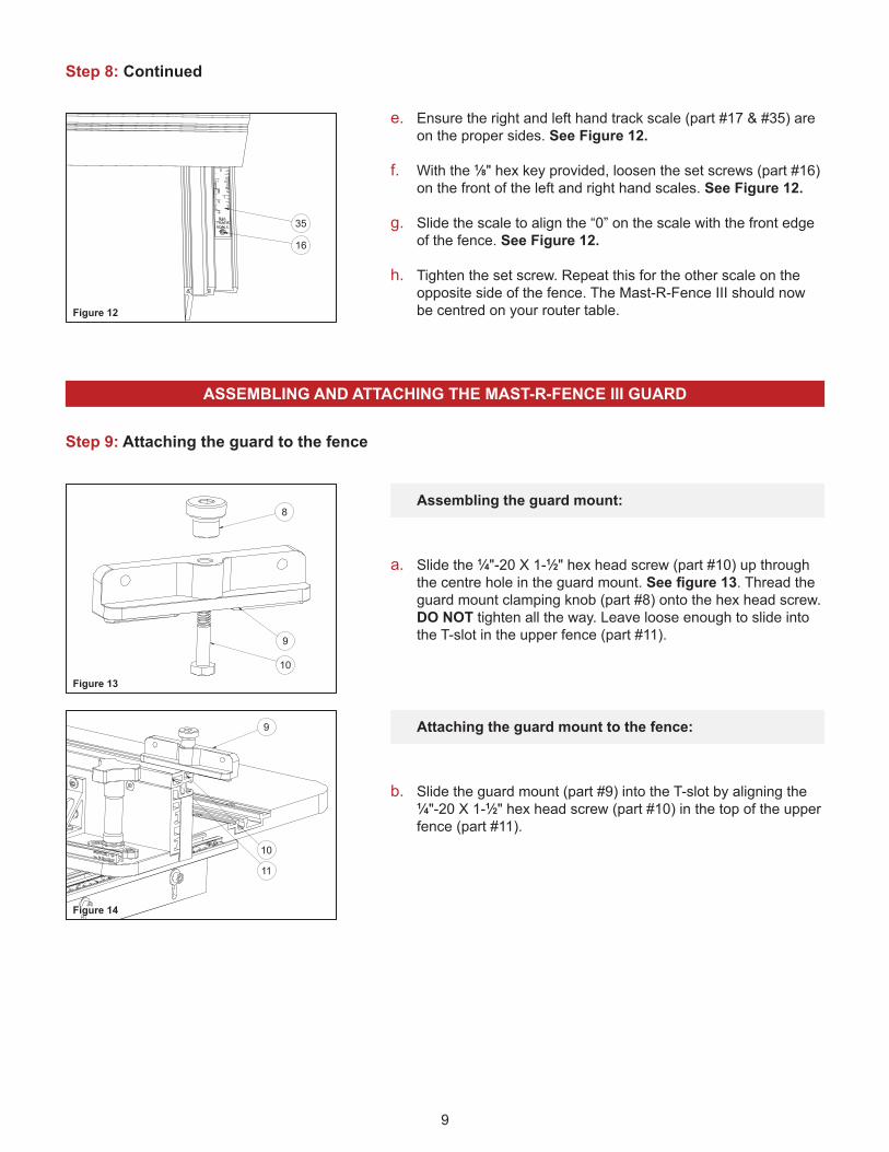
Step 9: Attaching the guard to the fence
a. Slide the 1⁄4"-20 X 1-1⁄2" hex head screw (part #10) up through the centre hole in the guard mount. See figure 13. Thread the guard mount clamping knob (part #8) onto the hex head screw. DO NOT tighten all the way. Leave loose enough to slide into the T-slot in the upper fence (part #11).
e. Ensure the right and left hand track scale (part #17 & #35) are on the proper sides. See Figure 12.
f. With the 1⁄8" hex key provided, loosen the set screws (part #16) on the front of the left and right hand scales. See Figure 12.
g. Slide the scale to align the “0” on the scale with the front edge of the fence. See Figure 12.
h. Tighten the set screw. Repeat this for the other scale on the opposite side of the fence. The Mast-R-Fence III should now be centred on your router table.
b. Slide the guard mount (part #9) into the T-slot by aligning the 1⁄4"-20 X 1-1⁄2" hex head screw (part #10) in the top of the upper fence (part #11).
10
9
8
Figure 13
16
35
Figure 12
9
10
11
Figure 14
Assembling the guard mount:
Attaching the guard mount to the fence:
Step 8: Continued
ASSEMBLING AND ATTACHING THE MAST-R-FENCE III GUARD
16
35
8
9
10
9
11
10

10
Step 9: Continued
a. Attach the guard (part #2) to the guard mount (part #9) using the (2) guard height adjustment knobs (part #1).
b. To adjust the height of the guard during use, loosen the guard height adjustment knobs and slide the guard to the desired height; then re-tighten.
9
2 1
Figure 15
Attaching the guard:
Step 10: Loosen the (4) fence face clamping knobs (part #22). See figure 16.
Step 11: To avoid damaging the wooden fence faces, slide to desired width so your fence faces completely clear your router bit. Re-tighten the (4) fence face clamping knobs to clamp the fence faces in place. See Figure 16.
22222222
Figure 16
ADJUSTING THE WOODEN FENCE FACE (PART #37) ON THE MAST-R-FENCE III
CAUTION ENSURE THE FENCE FACES COMPLETELY CLEAR THE
DIAMETER OF THE ROUTER BIT BEFORE STARTING THE ROUTER.
!
2 1
9
22 22 22 22
11
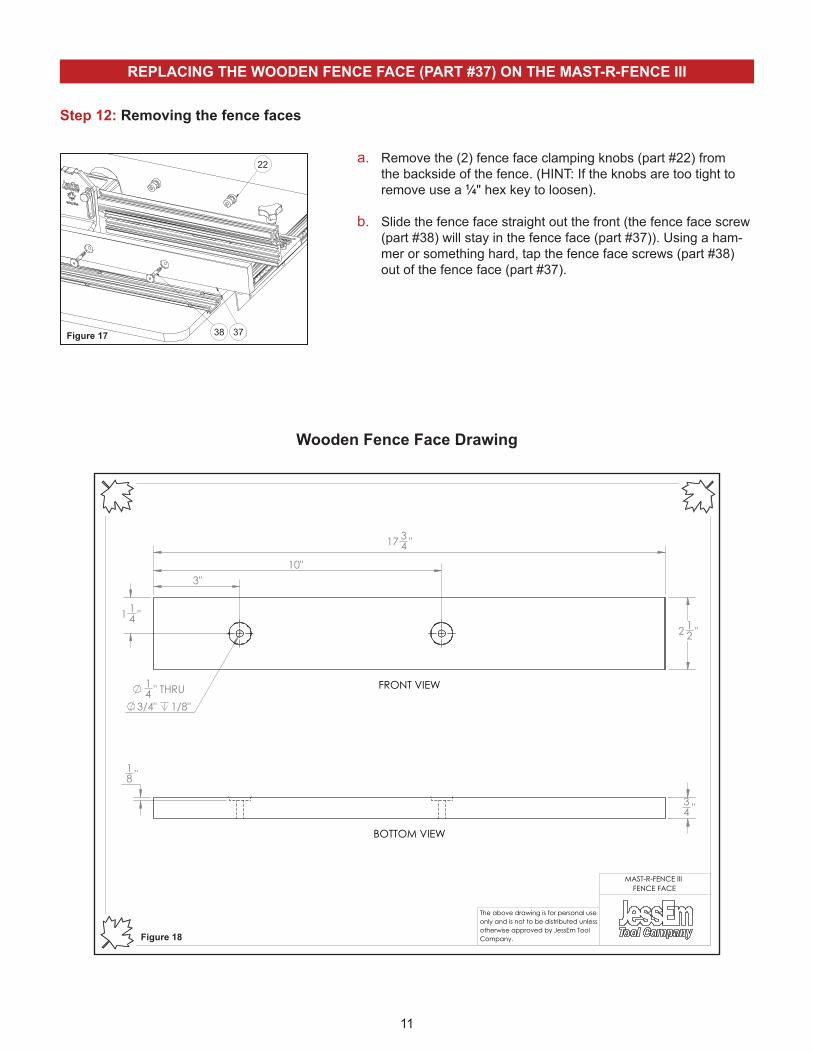
REPLACING THE WOODEN FENCE FACE (PART #37) ON THE MAST-R-FENCE III
Step 12: Removing the fence faces
a. Remove the (2) fence face clamping knobs (part #22) from the backside of the fence. (HINT: If the knobs are too tight to remove use a 1⁄4" hex key to loosen).
b. Slide the fence face straight out the front (the fence face screw (part #38) will stay in the fence face (part #37)). Using a ham-mer or something hard, tap the fence face screws (part #38) out of the fence face (part #37).
38 37
22
Figure 17
3" 10"
17 34 "
2 12 "
1 14 "
14 " THRU
3/4" 1/8"
FRONT VIEW
18 "
34 "
BOTTOM VIEW
The above drawing is for personal use only and is not to be distributed unless otherwise approved by JessEm Tool Company.
MAST-R-FENCE III FENCE FACE
Wooden Fence Face Drawing
Figure 18
22
3738

12
Step 13: Attaching new fence faces
a. Slide the fence face clamping knobs (part #38) into the previ-ously drilled holes in your new fence faces. See figure 19.
b. Slide the fence face clamping knobs into the slots in the fence uprights (part #12).
c. Reattach with clamping knobs (part #22).
38 37
22
Figure 19
MAST-R-FENCE III JOINTING
Step 14: Storage of shimming bars (when not in use)
Step 15: Using the shimming bars
a. Slide the shimming bars (part #33) into the shimming bar hold-ers (part #21) until the detent “clicks” into place.
a. Loosen the fence face clamping knobs (part #22) until there is enough play behind the fence face to slide the shimming bars behind.
b. Slide the fence shimming bars (part #33) into the matching grooves on the left hand fence upright (part #12, outfeed side).
c. When sliding the shimming bars into the left hand fence upright (part #12) match the laser engraved feed direction to the de-sired jointing spacing. (1⁄16" or 1⁄32").
d. Once the shimming bar is behind the fence face, tighten the fence face clamping knobs (part #22).
33
21
Figure 20
33
Figure 21
22
3738
21
33
33
13
363738
21
34
57
8 9 10 11 12 13 1617
18
19
2022
2324
25 27
21
28 23 29
3031
32
26
3335
6
3
14 15
34
14
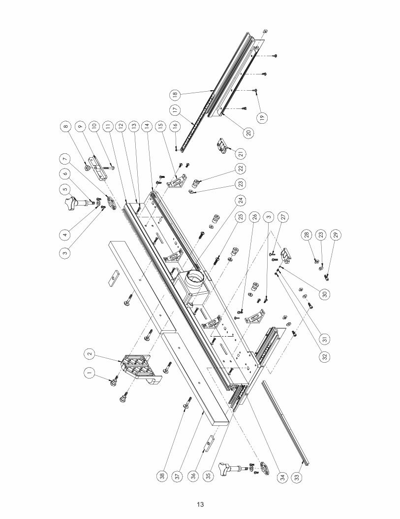
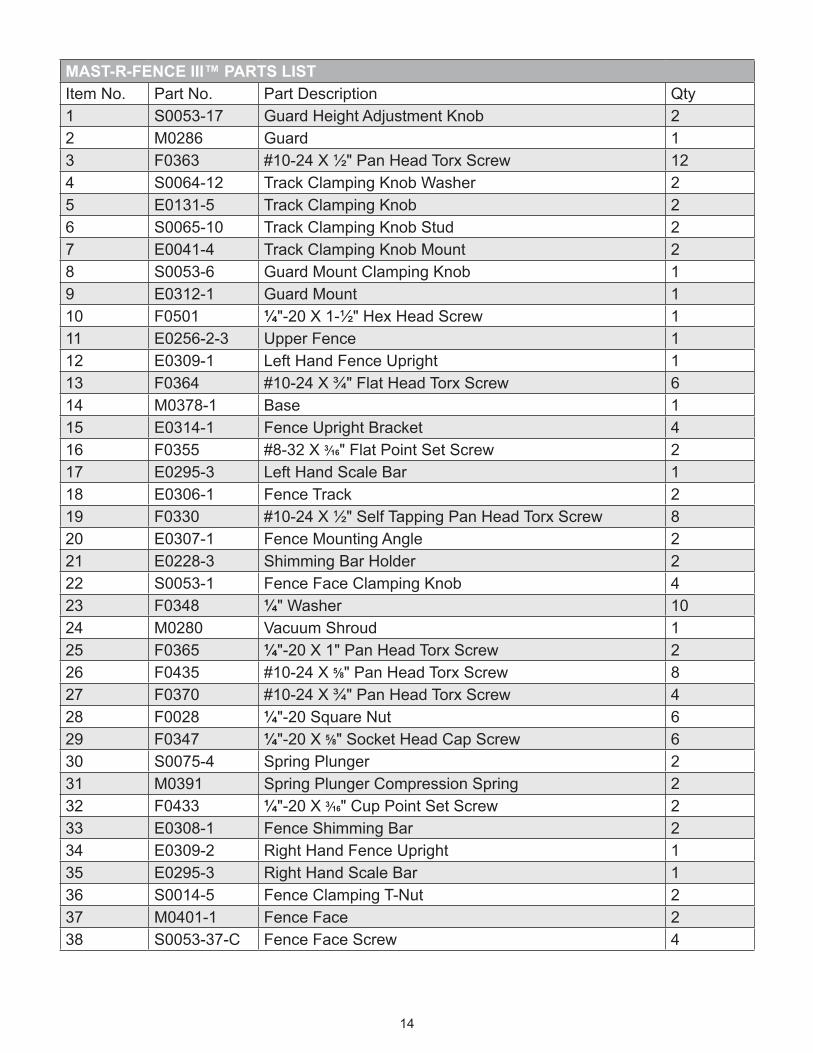
MAST-R-FENCE III™ PARTS LISTItem No. Part No. Part Description Qty1 S0053-17 Guard Height Adjustment Knob 22 M0286 Guard 13 F0363 #10-24 X ½" Pan Head Torx Screw 124 S0064-12 Track Clamping Knob Washer 25 E0131-5 Track Clamping Knob 26 S0065-10 Track Clamping Knob Stud 27 E0041-4 Track Clamping Knob Mount 28 S0053-6 Guard Mount Clamping Knob 19 E0312-1 Guard Mount 110 F0501 ¼"-20 X 1-½" Hex Head Screw 111 E0256-2-3 Upper Fence 112 E0309-1 Left Hand Fence Upright 113 F0364 #10-24 X ¾" Flat Head Torx Screw 614 M0378-1 Base 115 E0314-1 Fence Upright Bracket 416 F0355 #8-32 X 3⁄16" Flat Point Set Screw 217 E0295-3 Left Hand Scale Bar 118 E0306-1 Fence Track 219 F0330 #10-24 X ½" Self Tapping Pan Head Torx Screw 820 E0307-1 Fence Mounting Angle 221 E0228-3 Shimming Bar Holder 222 S0053-1 Fence Face Clamping Knob 423 F0348 ¼" Washer 1024 M0280 Vacuum Shroud 125 F0365 ¼"-20 X 1" Pan Head Torx Screw 226 F0435 #10-24 X 5⁄8" Pan Head Torx Screw 827 F0370 #10-24 X ¾" Pan Head Torx Screw 428 F0028 ¼"-20 Square Nut 629 F0347 ¼"-20 X 5⁄8" Socket Head Cap Screw 630 S0075-4 Spring Plunger 231 M0391 Spring Plunger Compression Spring 232 F0433 ¼"-20 X 3⁄16" Cup Point Set Screw 233 E0308-1 Fence Shimming Bar 234 E0309-2 Right Hand Fence Upright 135 E0295-3 Right Hand Scale Bar 136 S0014-5 Fence Clamping T-Nut 237 M0401-1 Fence Face 238 S0053-37-C Fence Face Screw 4