marx generator using pseudo spark switches_ ppc_2003_marx_generator
TRANSCRIPT

8/3/2019 Marx Generator Using Pseudo Spark Switches_ PPC_2003_Marx_Generator
http://slidepdf.com/reader/full/marx-generator-using-pseudo-spark-switches-ppc2003marxgenerator 1/4
Abstract Number #10318
MARX GENERATOR USING PSEUDOSPARK SWITCHES ∗
Andras Kuthi, Ray Alde, and Martin Gundersenξ,
Department of Electrical Engineering – ElectrophysicsUniversity of Southern California
Los Angeles, CA 90089-0271
Andreas Neuber
Department of Electrical & Computer Engineering
Texas Tech University Lubbock, TX 79409-3102
∗ This work was primarily funded by the Compact-Pulsed Power MURI program funded by the Director of Defense
Research and Engineering (DDR&E) and managed by the Air Force Office of Scientific Research (AFOSR) and wasalso funded by the Army Research Office (ARO).ξ email: [email protected]
Abstract
The design and preliminary operation of the major
subsystems of a Marx style pulse generator usingadvanced Pseudospark devices are presented. The bank
consists of three 150nF / 40kV capacitors connected withthree floating FS2000 type Pseudospark switches. These
switches can hold off 35 kV and pass up to 10 kA at
repetition rates approaching 1 kHz. The expected lifetime
of >200kC and the relatively low housekeeping power of <50 W make the Pseudospark switch an excellent
candidate in compact Marx generator applications.
Preliminary operation of the floating housekeeping unitsessential to the Marx generator is presented in detail.
I. INTRODUCTION
There is a need for high voltage, high current, compact
pulsed power sources at the 500 kV, 10 kA, and 500 ns parameter level. Few switches can handle such
parameters with any reliability. We have taken two
distinct approaches to such a compact pulse generator system. The first is based on the development of a multi-
gap, 200 kV rated Pseudospark switch and Transmission
Line Transformers [1], and the other, which we presenthere, is the Marx generator. Switches in Marx generators
need to hold off only a single stage voltage.
Traditionally, pressurized spark gaps and Thyratrons
have been used as high power Marx-bank switches. Spark gaps suffer from limited lifetime, low repetition rate and
erratic trigger performance, although modern versionshave built in UV preionization aiding in trigger reliability.
Thyratrons have much longer life, faster switch recovery
and precise, low-jitter triggering. However, they suffer
from low current capability, large size and very high
housekeeping power, making the Marx generator large
and expensive, mostly due to the floating housekeeping
power requirement.An excellent candidate switch is the Pseudospark
[2,3,4,5]. The Pseudospark is a glow discharge switch,
capable of operation at 35 kV and 10 kA, having fast (<
30 nS) rise time, small size and relatively low
housekeeping power requirement. Although an opticallytriggered version of the Pseudospark, called Back Lighted
Thyratron (BLT), had been used in a small prototypeMarx bank and proved to have the requisite low jitter and
short rise time [6], the presence of optical fiber inside the
hollow cathode cavity of the switch in contact with high
density plasma during the switch on-time made thisarrangement prone to impurity induced failure. Further
development of the optical trigger system is expected tolead to a superior switch, but presently the only available
commercial Pseudospark is based on electrical trigger.
Electrically triggered Pseudosparks can achieve, under
optimized conditions, subnanosecond jitter and delays onthe order of tens of nanoseconds [7]. After a large number
(~107) of pulses, the jitter usually increases to 10 – 20 ns,due to electrode erosion. In the Marx bank application the
important issues to be resolved are the stability and
reproducibility of delay and jitter among all the switches
and the practicality of a highly efficient, compact floating power supplied to each switch. These are interrelated
issues, as the delay is a strong function of the trigger pulse
shape and amplitude as well as of the exact gas pressureinside the switches. Thus, the main design and
implementation problem lies in the floating housekeeping
power units of each switch.In order to examine these issues we have designed and
constructed a three stage Marx generator using the
Preprint

8/3/2019 Marx Generator Using Pseudo Spark Switches_ PPC_2003_Marx_Generator
http://slidepdf.com/reader/full/marx-generator-using-pseudo-spark-switches-ppc2003marxgenerator 2/4
commercial FS2000 Pseudospark switch. Isolated floating power is supplied to the switches by a novel high
frequency and high efficiency Class-E power converter
[8]. The floating trigger generators are of a flyback
design [9]. Individual trigger signals are passed to thefloating units by optical fibers. The gas pressure control
is feedback stabilized, using optical signal isolation.
II. DESIGN
The Marx bank is designed around the commercially
available FS2000 type Pseudospark switch shown in
Fig. 1. The FS2000 can hold off 35 kV and pass up to10 kA at repetition rates approaching 1 kHz. The
expected switch lifetime is >200 kC. The compact Marxgenerator is housed in an oil filled steel container of
dimensions 46 cm x 92 cm x 46 cm.
Absolute maximum housekeeping requirements are the
following: Gas reservoir heater = 4 V and 5 A; Keep alivedischarge = -2 kV and 2 mA; Trigger power supply =
10 W.
Figure 1. The FS2000 Pseudospark switch:
length = 173 mm, cathode flange diameter = 92 mm
In order to test the system at maximum switch capacitya three stage Marx bank with 30 kV per stage was
selected. The peak output voltage of the generator is then90 kV. The maximum switch current of 9 kA leads to a
load impedance of 10 Ω. The test load is an 18” longKanthal-Globar ceramic resistor.
The bank architecture is grounded first switch, negative
output type as shown in Fig. 2. In this bank all capacitors
float, but the first switch cathode is at ground potential.Thus, the floating switches only have to be insulated for
30 kV, respective 60 kV, and not for the full bank outputof 90 kV.
The intermediate charging resistors are 1 k Ω, 8” long
ceramic resistors. The main charging resistor is 500 k Ω.
The energy storage elements are 150 nF / 40 kV oil filled plastic HV capacitors manufactured by Maxwell. The
erected bank capacitance of 50 nF and the 10 Ω loadresistance determine the 500 ns pulse length.
Optical Fibre Isolated Control Circuit and Transformer Isolated Power
Trig.K.A.
Floating SwitchHousekeeping
150nF
1k
FS2000
1k
Trig.K.A. 150nF
1k
1k
Trig.K.A.
150nF
1k
10
-90kV pulse out
Heater Heater Heater
+30 kVVcharge in
500k
Anode
Cathode
Trigger
Keep-alive
Heater
Figure 2. Marx-Generator with Pseudospark Switches
A. Housekeeping
Although the first switch cathode is directly grounded
we decided to use even here a floating housekeeping power supply, identical to the other two stages (Fig. 3).
The reason is that at the 10 kA load current level it is verydifficult to avoid ground noise interference with the
control and diagnostic circuits if a direct ground
connection exists between the low current, low voltagecontrol and the high current bank circuits.
Isolation Barrier
3 - 5 Vac To Heater
Rectifier
filter regulator
Rectifier filter regulators
+5 V
Ret.
+48 V
Ret.
+12 V+5 V
Keep-alive current sens.
5 V to 2 kV DC-DC conv.
Flyback Trigger Gen.
Optical fibers
Trig. In
I out
Figure 3. Block diagram of the floating housekeeping
system
Preprint

8/3/2019 Marx Generator Using Pseudo Spark Switches_ PPC_2003_Marx_Generator
http://slidepdf.com/reader/full/marx-generator-using-pseudo-spark-switches-ppc2003marxgenerator 3/4
The entire housekeeping system fits into an aluminum box of dimensions 7.9 cm x 16.6 cm x 15.2 cm, enclosing
the cathode side of the Pseudospark switch as well as
shown in Figure 4.
Figure 4. The Marx bank and its components
Local floating housekeeping power for each switch is provided by a high frequency isolation transformer. The
transformer is wound on a ferrite toroid core, 3.5 cm ID,
6 cm OD, 1.27 cm high, 3F4 material. The primary
winding is 10 turns of 40 kV silicon insulated wire. This primary winding is the main HV insulation barrier. There
are a set of three secondary windings: 2 x 5 turns of 18 awg magnet wire, bifilar wound, for the heater; 6 turns
of 18 awg wire for the keep alive power; and 40 turns of
22 awg wire for the trigger supply.
The Flyback trigger circuit is shown in Fig. 5. In this
configuration the trigger MOSFET switch is off when thePseudospark fires, and so the return flash from the trigger electrode does not affect the circuit. Rapid and hard turn-
off of the MOSFET is assured by the P-channel shorting
switch across the main MOSFET gate. The optical fiber
receiver and MOSFET gate driver are of standard designand are not shown.
+
T2
T1D1 D10
Gate in
ID sense
+48 Vdc in
+
50
50k
-4 kV out
22nF
50
50
MUR11008 50
470uF 470uF
250uH
1
APT10035JLL
IRF7406
MUR1100
Vsense
Figure 5. The Flyback trigger circuit
The keep-alive power, -2 kV at ~1 mA, is generated by
a commercial DC to DC converter, model 5VV2 fromPICO Electronics. This unit is small, efficient and fits
into the limited space available in the housekeeping
enclosure attached to the Pseudospark switch. The keep-alive current is used as a pressure gauge. The current is
sensed by a resistor, and is converted into a 0 – 10 mA
signal through a LED transmitter as shown in Figure 6.
The analog optical signal is passed through an opticalfiber across the isolation barrier to an optical receiver on
the main control board.
+5V in
+5V ret.
-2kV ret.
-2kV
5VV2PICO
330
2.2k
470k to PSP
keep-alive
100
HFBR-1414T
Figure 6. The keep-alive current sense circuit
B. Power Converter The main power converter is a Class-E tuned
switching amplifier. The characteristics of this class of
RF amplifiers is that the switching element, in our case a1000 V, 100 A rated MOSFET, turns on at the moment
when the drain voltage is zero, so there is no dissipationassociated with the discharging of the drain capacitance.
This is accomplished by a resonant load network (Fig. 7).
22n
5n
ResonantLoad Network
47uH
250uH
APT10035
50
4422
4046
VCO-
+
+24V
+12V
I k-a
Figure 7. The Class-E power converter
The transformer with its leakage inductance is part of
the load network, so is the MOSFET’s intrinsic draincapacitance. Thus, the parasitic elements of the major
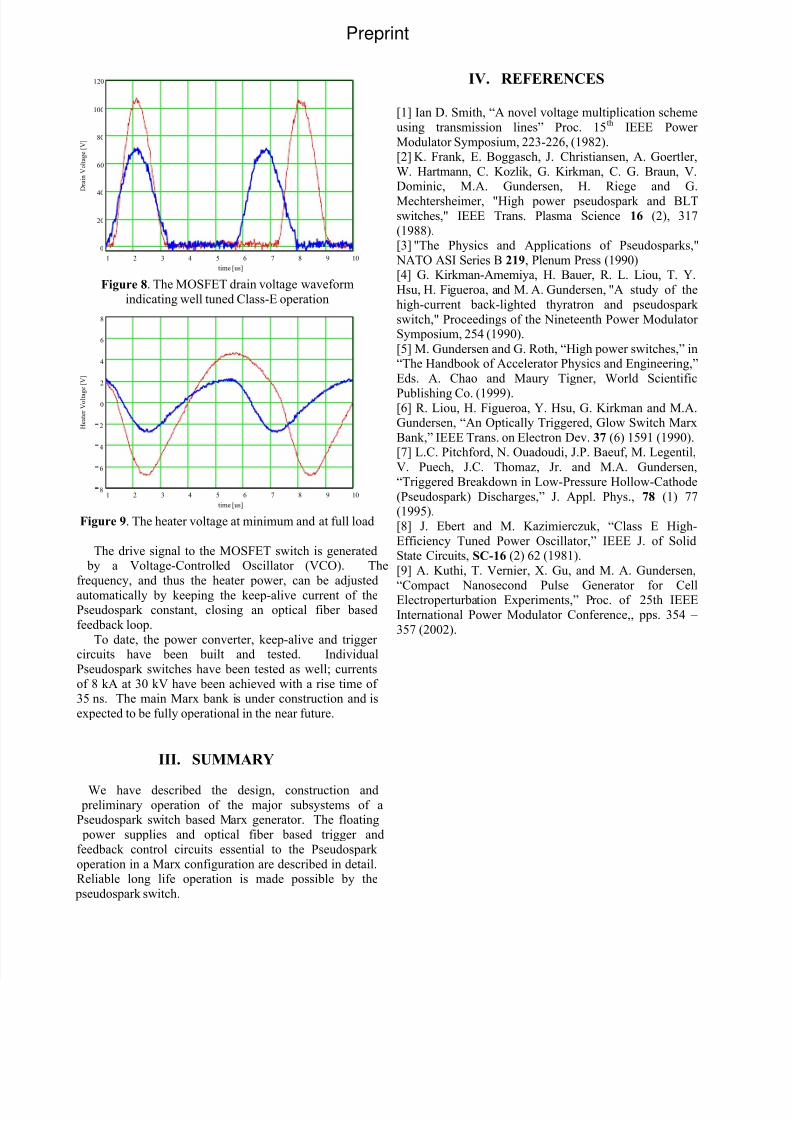
components of the circuit are working with, not againstthe design. Figure 8 shows the return of the drain voltage
to zero at the turn-on of the MOSFET, at both full power
and at minimum power to the Pseudospark heater. The
heater waveform is shown in Figure 9.The range of operating frequency is 150 KHz at
maximum power to 200 kHz at minimum. Heater power varies more than a factor 4 over this range. The
efficiency of the power converter and transformer system
is better than 85% over the full power range.
On the secondary side of the transformer Schottkyrectifiers must be used due to the high operating
frequency. Losses contributed by inferior fast rectifiers
can be significant and may lead to rectifier failure.
Preprint
8/3/2019 Marx Generator Using Pseudo Spark Switches_ PPC_2003_Marx_Generator
http://slidepdf.com/reader/full/marx-generator-using-pseudo-spark-switches-ppc2003marxgenerator 4/4
IV. REFERENCES
1 2 3 4 5 6 7 8 9 10
0
20
40
60
80
100
120
time [us]
D r a i n V o l t a g e [ V ]
[1] Ian D. Smith, “A novel voltage multiplication scheme
using transmission lines” Proc. 15th IEEE Power
Modulator Symposium, 223-226, (1982).[2] K. Frank, E. Boggasch, J. Christiansen, A. Goertler,
W. Hartmann, C. Kozlik, G. Kirkman, C. G. Braun, V.Dominic, M.A. Gundersen, H. Riege and G.
Mechtersheimer, "High power pseudospark and BLTswitches," IEEE Trans. Plasma Science 16 (2), 317
(1988).[3] "The Physics and Applications of Pseudosparks,"
NATO ASI Series B 219, Plenum Press (1990)[4] G. Kirkman-Amemiya, H. Bauer, R. L. Liou, T. Y.
Hsu, H. Figueroa, and M. A. Gundersen, "A study of the
high-current back-lighted thyratron and pseudospark
switch," Proceedings of the Nineteenth Power Modulator Symposium, 254 (1990).
Figure 8. The MOSFET drain voltage waveform
indicating well tuned Class-E operation
1 2 3 4 5 6 7 8 9 108
6
4
2
0
2
4
6
8
time [us]
H e a t e r V o l t a g
e [ V ]
[5] M. Gundersen and G. Roth, “High power switches,” in“The Handbook of Accelerator Physics and Engineering,”
Eds. A. Chao and Maury Tigner, World Scientific
Publishing Co. (1999).[6] R. Liou, H. Figueroa, Y. Hsu, G. Kirkman and M.A.Gundersen, “An Optically Triggered, Glow Switch Marx
Bank,” IEEE Trans. on Electron Dev. 37 (6) 1591 (1990).[7] L.C. Pitchford, N. Ouadoudi, J.P. Baeuf, M. Legentil,
V. Puech, J.C. Thomaz, Jr. and M.A. Gundersen,
“Triggered Breakdown in Low-Pressure Hollow-Cathode
(Pseudospark) Discharges,” J. Appl. Phys., 78 (1) 77(1995).
Figure 9. The heater voltage at minimum and at full load [8] J. Ebert and M. Kazimierczuk, “Class E High-
Efficiency Tuned Power Oscillator,” IEEE J. of SolidState Circuits, SC-16 (2) 62 (1981).The drive signal to the MOSFET switch is generated
by a Voltage-Controlled Oscillator (VCO). The
frequency, and thus the heater power, can be adjusted
automatically by keeping the keep-alive current of thePseudospark constant, closing an optical fiber based
feedback loop.
[9] A. Kuthi, T. Vernier, X. Gu, and M. A. Gundersen,
“Compact Nanosecond Pulse Generator for CellElectroperturbation Experiments,” Proc. of 25th IEEE
International Power Modulator Conference,, pps. 354 –
357 (2002).To date, the power converter, keep-alive and trigger
circuits have been built and tested. Individual
Pseudospark switches have been tested as well; currents
of 8 kA at 30 kV have been achieved with a rise time of 35 ns. The main Marx bank is under construction and is
expected to be fully operational in the near future.
III. SUMMARY
We have described the design, construction and preliminary operation of the major subsystems of aPseudospark switch based Marx generator. The floating
power supplies and optical fiber based trigger and
feedback control circuits essential to the Pseudospark
operation in a Marx configuration are described in detail.Reliable long life operation is made possible by the
pseudospark switch.
Preprint