martin audio – ma200q amplifier€¦ · martin audio – ma200q amplifier e nglish 3! 9. connect...
TRANSCRIPT

Martin Audio – MA200Q Amplifier
EN
GLISH
1
CONTENTS (ENGLISH) Page No1 CONTENTS MA200Q USER GUIDE 12 APPROVALS 23 WARNINGS 2
3.1 EXPLANATION OF GRAPHICAL SYMBOLS 23.2 WARNING 23.3 CAUTION 23.4 IMPORTANT SAFETY INSTRUCTIONS 23.5 USER RESPONSIBILITY 3
3.5.1 LOUDSPEAKER DAMAGE 33.5.2 LOUDSPEAKER OUTPUT HAZARD 33.5.3 RADIO INTERFERENCE 4
4 INTRODUCTION 44.1 UNPACKING 44.2 FRONT PANEL 44.3 REAR PANEL 5
5 REAR PANEL FEATURES 65.1 GAIN 65.2 SENSITIVITY 65.3 LINK SWITCH 75.4 OPERATING MODES 7
5.4.1 STEREO MODE 75.4.2 NOTES FOR AMPLIFIER TESTING 75.4.3 TANDEM MODE 85.4.4 BRIDGE MONO MODE 85.4.5 BRIDGE MONO MODE FEATURES 8
6 INSTALLATION 96.1 MOUNTING 96.2 COOLING 96.3 OPERATING VOLTAGE 96.4 GROUNDING 106.5 POWER CONSUMPTION 10
6.5.1 CALCULATION 117 CONNECTIONS 11
7.1 INPUT CONNECTIONS 117.1.1 BALANCED INPUTS 117.1.2 UNBALANCED INPUTS 12
7.2 CONNECTING LOUDSPEAKERS 128 OPERATION 13
8.1 OPERATION PRECAUTIONS 138.2 POWERING UP – SOFT START 148.3 INPUT ATTENUATORS 148.4 INDICATORS 14
9 PROTECTION FEATURES 149.1 OUTPUT LIMITER 149.2 THERMAL PROTECTION 159.3 VHF PROTECTION 159.4 SHORT CIRCUIT PROTECTION 159.5 AC MAINS VOLTAGE PROTECTION 159.6 DC PROTECTION 15
10 MAINTENANCE 1610.1 TROUBLESHOOTING 16
11 WARRANTY 1712 SPECIFICATIONS MA200Q 18
Martin Audio – MA200Q Amplifier
EN
GLISH
2
2 APPROVALS
This equipment conforms to the requirements of the EMC directive 89/336/EEC, amended by92/31/EEC and 93/68/EEC and the requirements of the Low Voltage Directive 73/23/EEC,
amended by 93/68/EEC.
Standard Applied EMC Emission EN55103-1, E3EMC Immunity EN55103-2, E3, with S/N below 1% at normal operation level.Electrical Safety EN60065, Class I
3 WARNINGS
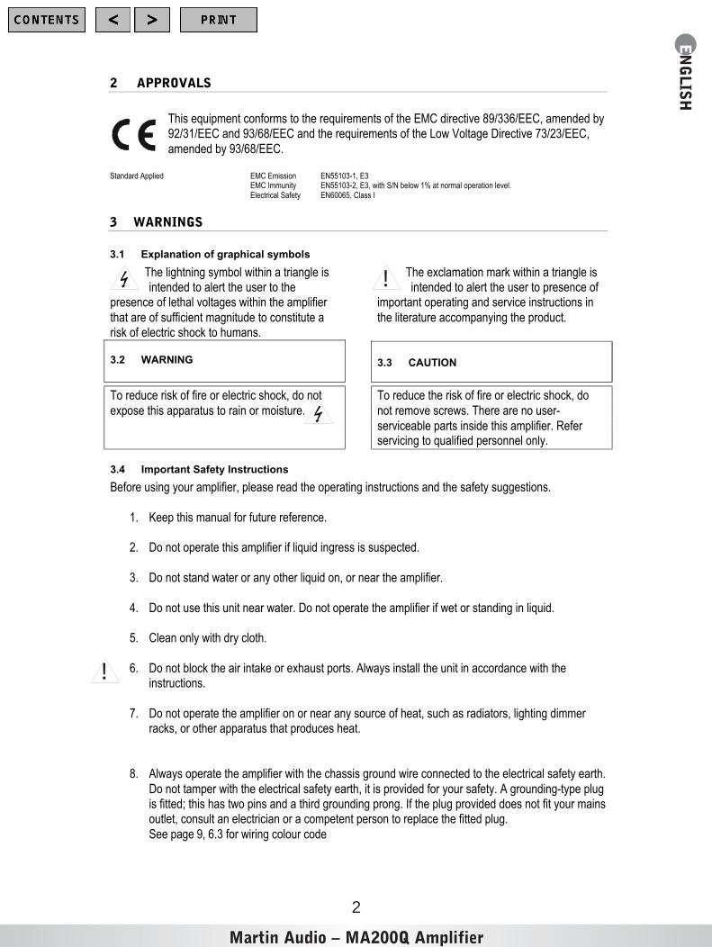
3.1 Explanation of graphical symbols
The lightning symbol within a triangle isintended to alert the user to the
presence of lethal voltages within the amplifier
that are of sufficient magnitude to constitute arisk of electric shock to humans.
The exclamation mark within a triangle isintended to alert the user to presence of
important operating and service instructions in
the literature accompanying the product.
3.2 WARNING
To reduce risk of fire or electric shock, do not
expose this apparatus to rain or moisture.
3.3
CAUTION
To reduce the risk of fire or electric shock, do
not remove screws. There are no user-
serviceable parts inside this amplifier. Referservicing to qualified personnel only.
3.4 Important Safety Instructions
Before using your amplifier, please read the operating instructions and the safety suggestions.
1. Keep this manual for future reference.
2. Do not operate this amplifier if liquid ingress is suspected.
3. Do not stand water or any other liquid on, or near the amplifier.
4. Do not use this unit near water. Do not operate the amplifier if wet or standing in liquid.
5. Clean only with dry cloth.
6. Do not block the air intake or exhaust ports. Always install the unit in accordance with theinstructions.
7. Do not operate the amplifier on or near any source of heat, such as radiators, lighting dimmerracks, or other apparatus that produces heat.
8. Always operate the amplifier with the chassis ground wire connected to the electrical safety earth.
Do not tamper with the electrical safety earth, it is provided for your safety. A grounding-type plugis fitted; this has two pins and a third grounding prong. If the plug provided does not fit your mainsoutlet, consult an electrician or a competent person to replace the fitted plug.
See p ag e 9, 6.3 for wiring colour code
!
!
Martin Audio – MA200Q Amplifier
EN
GLISH
3
!
9. Connect only to AC power outlets rated 230-240V (or 100-120V), 50-60Hz.
10. Do not use this amplifier if the mains cable is damaged or frayed, particularly check where themains cable exits the amplifier and the mains plug. Protect the mains cable from being walkedupon or rolled over by heavy objects.
11. Only use accessories specified by the manufacturer.
12. The amplifier is intended to use in a 19” rack. Follow the mounting instructions. When racks withwheels are used, use caution to avoid injury from tipping when in motion.
13. Unplug this apparatus during lightning storms or when unused for long periods of time.
14. Do not connect an amplifier output in parallel or series with any other amplifier’s output. Do not
connect the amplifier output to any other voltage source, such as a battery, mains outlet, orpower supply, regardless of whether the amplifier is turned on or off.
15. Do not run the output of any amplifier back into another amplifier's input.
16. Refer all servicing to qualified personnel only. Servicing is required when the apparatus has been
damaged in any way such as:• Mains cable, or plug is damaged• Liquid has entered the amplifier
• An object has fallen into the amplifier• The amplifier has been exposed to rain or moisture• The amplifier does not operate normally
• The amplifier has been dropped or the enclosure is damaged
17. Do not remove top or bottom covers. Removal of the cover will expose hazardous voltages.
There are no user serviceable parts inside and removal may void the warranty.
18. An experienced person should always supervise inexperienced adults or minors when using
professional audio equipment.
3.5 User responsibility
3.5.1 Loudspeaker damage
Your amplifier is very powerful and can be potentially dangerous to both loudspeakers and humansalike. Many loudspeakers can be easily damaged or destroyed by overpowering, especially withthe high power available from a bridged amplifier. Always check the loudspeaker’s continuous
and peak power capabilities. Even when using the amplifier’s front panel attenuator to reduce the gain, it is still possible to reach fulloutput power, if the input signal level is high enough.
3.5.2 Loudspeaker output hazard
Power amplifiers are capable of producing hazardous output voltages. To avoid the risk of electricshock, do not touch any exposed loudspeaker wiring, when the amplifier is operating. See page
12 Connecting loudspeakers.
!

Martin Audio – MA200Q Amplifier
EN
GLISH
4
3.5.3 Radio interference
A sample of this product has been tested and complies with the limits for the European Electro MagneticCompatibility (EMC) directive. These limits are designed to provide reasonable protection against harmful
interference from electrical equipment. This product uses radio frequency energy and if not used orinstalled in accordance with these operating instructions, may cause interference to other equipment,such as radio receivers. Compliance with the (EMC) directive does not automatically guarantee non-
disturbance of susceptible equipment in close proximity to this amplifier.If this amplifier is suspected of causing interference this can be easily checked by powering the amplifieron and off and observing the disturbance. The user can correct the interference by one or more of the
following measures:• Re - orientate or relocate the receiver's antenna.• Increase the distance between the amplifier and the effected equipment.
• Connect the mains cable to a socket on a different circuit from that to which the affected unitis connected.
• Check if the affected equipment complies with the EMC limits for immunity, (CE-labelled). If
not, address the problem with the manufacturer or supplier. All electrical products sold in theEC must be approved for immunity against electromagnetic fields, high voltage flashes, andradio interference.
• Consult your dealer or an experienced radio/TV technician for help
4 INTRODUCTION
Thank you for purchasing a Martin Audio power amplifier. This manual contains important information onoperating your amplifier correctly and safely. Please take some time to read this manual and familiarizeyourself with the advanced features of this amplifier.
4.1 Unpacking
Each Martin Audio MA series amplifier is built to the highest standard and thoroughly inspected before it
leaves the factory. After unpacking the unit, examine it carefully for any signs of transit damage andinform your dealer if such damage is found. It is suggested that you retain the original packaging so thatthe unit can be repackaged at a future date if necessary.
Please note that Martin Audio and its distributors cannot accept responsibility for damage to any returnedproduct through the use of non - approved packaging.
4.2 Front Panel
dB 0-8 0-4 0 -1-2 0-1 6-1 2-1 0 -7 -5-3CH.A CH.B CH.C CH.D-2 0-4 0-8 0-1 2-1 6 -3-10dB -5-7-1 0 -1 6-1 2-8 0-4 0-2 0 -3dB 0 -1-1 0 -7 -5 -8 0-4 0 0dB-1 2-1 6 -7 -3-1-5-10 01
8 23 5 4 3 2 54 7 6
1 1 1 1PROTECTCLIP-4 0dBON MA200QPROTECTCLIP-40dBON
1 . Input lev e l at te nua tor s
The se c o ntro ls ar e u se d to se t the s ign al le ve l e nter in g the amplifier . The y ar e c alibr ated in d B's to a ss is tthe s etu p of ac tive lo ud s pe ak er sy ste ms . (Se e pa g e 1 4) .

Martin Audio – MA200Q Amplifier
EN
GLISH
5
2 . Pr ot e ct indica tor LED This indicator illuminates if the amplifier attempts to function above its maximum operating temperature
(90°C). The indicator first comes on as a warning, to either turn down the input level or check the coolingarrangements, after which point the amplifier will mute the input signal. When the cooling fans havereturned the output heat sinks back to the normal operating temperature the input signal is un-muted.
This in d ic ato r also illu min ates wh en sign als a bo v e 12 k H z at fu ll p o we r a re d ete cted at the ou tp u t te rmina ls o r if th e sh o rt c ir c uit p ro te ction is a ctiv a te d. Sh ou ld th is oc cu r the in pu t sig na l is mu te d , an d the p r oc es s r ep ea ts un til the VH F sig na l is no lo ng er p r es en t o r th e s ho r t circ u it is r emov e d. ( Se e p ag e 1 5) .
3 . Clip/limit indic a torThis in d ic ato r sign a ls w h en the amplifier o u tp ut is c lip ping or limiting . It ha s two differ e nt in dica tio n sta te s:
W he n th e c lip limite r is en ga ge d , it ha s a s ho rt time c o ns ta n t an d it illumin ate s br iefly . ( Se e p ag e 1 5) .W he n th e c lip limite r is no t en g ag ed , it ha s a n inc re as e d time co ns tan t a nd it illumina te s for a lo ng er pe rio d.
4. Signal present indicatorThis LED Illu mina te s a t – 40 dB b e lo w full ou tpu t s ig na l.
5 . On indica t or The four bottom green ”ON” LED's indicate that the output circuits are receiving the correct rail voltage.
6 . Pow er s w it chTur ns th e ma ins p ow e r “O N ” or “ O FF”.(See page 9 and12)
7 . Fan grille f ilt er sA g rille w ith foa m filte r s is lo ca te d o n th e fro n t pa ne l to p re ve nt du st fr om e n te rin g th e a mp lifie r. Th e gr ille is
r emov ab le fo r e as y c le an ing o f the filter b y s imp ly p ullin g the m off. Th e foa m filte r s ho uld a lw a ys b e u se d.
8 . Ca rr y /prot ec tion ha ndle
Both handles can be used to carry the amplifier; they also act as protection for the front panel. In fixedinstallations or where rack front covers are too shallow, they may be removed by unscrewing the retainingbolts behind the front panel.
4.3 Rear Panel
Ser. N:o
OUTPUTS C,D
CH.D CH.C INPUTS CH.B CH.A
Link /
Brid g
eC
+D
LinkB
+C
Must be groundedClip Limiter B
Clip Limi ter AClip Limi ter C
Clip Limi ter D
Fixed gain 32 dB
Off
On Off
Link/
Brid g
eA+
B
STEREO1+ CH.A+1- CH.A-2+ CH.B+2- CH.B-
BRIDGEPin 1+ Spk+ 2- Spk-
STEREO1+ CH.C+1- CH.C-2+ CH.D+2- CH.D-
BRIDGEPin 1+ Spk+ 2- Spk-
Made in t he EEC byMARTIN AUDIO MA200Q
XLRPin 1 Scrn Sleeve 2 Pos Tip 3 Neg Ring
1/ 4“
230-240V 50-60Hz
On O ffOnOn Of
f
OUTPUTS A,B
1 3 4 4 4 4 3 1
3 9 35 77
1. Output / Speaker connector
The N eu tr ik Spe ak on co nn e ctor is u se d o n th e o utp uts of th e a mp lifie r a full de s cr ip tio n ca n b e fou nd in the o pe ra tio n se c tion . ( Se e p ag e1 2) .

Martin Audio – MA200Q Amplifier
EN
GLISH
6
!
3. Clip limiter switchTurns the clip limiter “ON” (switch IN position) or “OFF” (switch OUT position). (See page13).
4. Input signal XLR.The Neutrik Combo jack is used which also features a _” TRS phone jacks. (Pin 2 is “hot”, see page10).
5. Link switch. Allows a single input to drive channels B and C simultaneously.
7. Link / bridge switch. Allows a single input to drive channels A and B and / or channels C and Dsimultaneously. Also used for bridged operation of channel pairs (See page 6).
9. AC Mains cable. WARNING!A label just below the mains cable on the rear of the amplifier indicates the selected ACmains operating voltage. Connect the mains cable only to the AC source referred to on the
label.
5 REAR PANEL FEATURES
5.1 Gain
The gain of the MA200Q is fixed at 32 dB.
5.2 Sensitivity
Sensitivity is volts (rms) or dBu (referred to 0.775Vrms) that are required to obtain full output power. Asthe output power varies with the load impedance, the table below lists sensitivity versus loadconfiguration.
MA200QLOAD CONFIGURATION Volt rms dBu
16 ohmsQuad (4 channe l ) 0 . 81 0 . 4
8 ohmsQuad (4 channe l ) 0 . 81 0 . 4
4 ohmsQuad (4 channe l ) 0 . 71 - 0. 8
2 ohmsQuad (4 channe l ) 0 . 58 - 2. 5
16 ohmsS tereo ( 2 channels bridge d ) 0 . 98 2 . 1
8 ohmsS tereo ( 2 channels bridge d ) 0 . 71 - 0. 7
4 ohmsS tereo ( 2 channels bridge d ) 0 . 59 - 2. 4
Sensi tivity

Martin Audio – MA200Q Amplifier
EN
GLISH
7
!
230-240V 50-60Hz
1/ 4 “XLR
3 Neg Ring 2 Pos TipPin 1 Scrn Sleeve
Must be grounded
Le gdirB
/kni
D+
C
Fixed gain 32 dB
LC
+Bkni L
B+
Ae gdirB/k
ni
CH.D CH.C INPUTS CH.B CH.A
5.3 Link switch
The L in k s witch es lo ca te d o n th e r ea r p an el (b etw ee n th e fou r XLR in pu t c on ne cto rs ) a re for ch an g in g th e o pe ra tin g mo d es o f the a mplifie r . By us in g a c omb in atio n o f the se s w itch e s an d inp ut /o utpu t w ir ing it isp os sible to h av e se v er al op er ating c o nfig ur a tion s . (See be lo w , se ction 5 .2) .
5.4 Operating modes
5.4.1 Stereo mode
For 2 x stereo, 2 x bi amp or 4 channel (quad)use, all channels operate independently of each
other, and all the link switches are OUT. For a 2 xstereo configuration the input designation is CH Aleft input 1, CH B right input 1, CH C left input 2,
and CH D is right input 2. For 2 x bi amp CH Ainput would be LF1, CH B input HF1, CH C inputLF2 and CH D input HF2.
The attenuators on the front panel will controlthe respective channels levels.
Never connect either output terminal to ground or in parallel. The recommended minimum
impedance, for quad or tandem stereo operation, is 2 ohms per channel.
5.4.2 Notes for amplifier testing
NOTE: Channels B and D are always polarity reversed on the input, and polarity reversed back
on the output. On channels B and D outputs, the positive output voltage with respect to 0Vappears on pin -2 of the Speakon connector. Channel A and C outputs are connected with normalpolarity. By having channel A and B (and C and D) operating in opposite polarity, the energy storage in
the power supply is more efficient. This is significant for signals below 100 Hz (sub bass etc.) andimproves the power bandwidth. Be sure to use balanced inputs on all measurement equipment(including oscilloscope probes) if you are bench testing.
Martin Audio – MA200Q Amplifier
EN
GLISH
8
5.4.3 Tandem mode
In tandem mode two or four of the amplifiers inputs are linked together. To use only one input signal todrive inputs A or B press the (A+B link/bridge) switch and connect a signal to inputs A or B.
In this configuration loudspeaker 1 would then be connected across +1 and -1, and loudspeaker 2 across+2 and -2 of the OUTPUT A, B Speakon connector.To use only one input signal to drive inputs C and D press the (C+D link/bridge) switch and connect a
signal to inputs C or D, loudspeaker 3 would be connected across +1 and –1 and loudspeaker 4 across+2 and -2 of the OUTPUT C, D Speakon connector.To use only one input signal to drive all four channels, press “IN” the A+B link/bridge switch, the C+D
link/bridge switch, and the link B+C switch. All attenuators are active, allowing you to set different levels for each channel. Note that only the inputsare connected in parallel. This is NOT a parallel output mode. Never connect either output terminal to
ground or in parallel.You can use the remaining input connectors to parallel off “Daisy-chain” signal to other amplifiers.NOTE: Always turn off the Link switches when using the amplifier for dual Bi-amping.
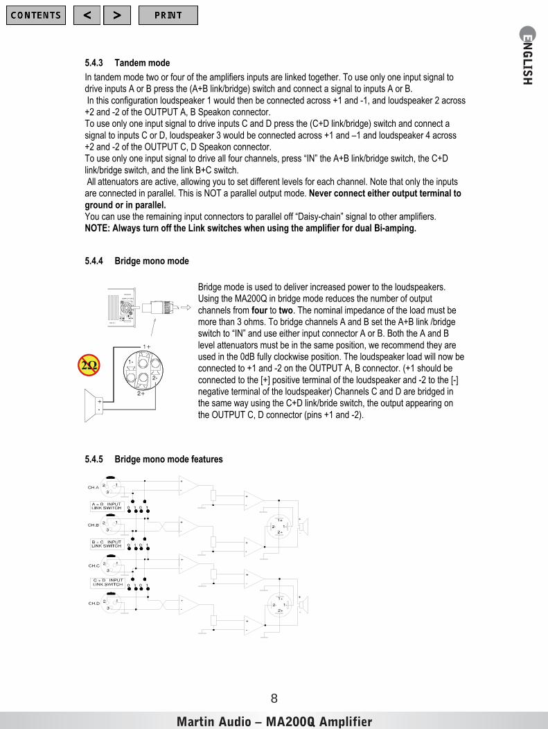
5.4.4 Bridge mono mode
Bridge mode is used to deliver increased power to the loudspeakers.Using the MA200Q in bridge mode reduces the number of output
channels from four to two. The nominal impedance of the load must bemore than 3 ohms. To bridge channels A and B set the A+B link /bridgeswitch to “IN” and use either input connector A or B. Both the A and B
level attenuators must be in the same position, we recommend they areused in the 0dB fully clockwise position. The loudspeaker load will now beconnected to +1 and -2 on the OUTPUT A, B connector. (+1 should be
connected to the [+] positive terminal of the loudspeaker and -2 to the [-]negative terminal of the loudspeaker) Channels C and D are bridged inthe same way using the C+D link/bride switch, the output appearing on
the OUTPUT C, D connector (pins +1 and -2).
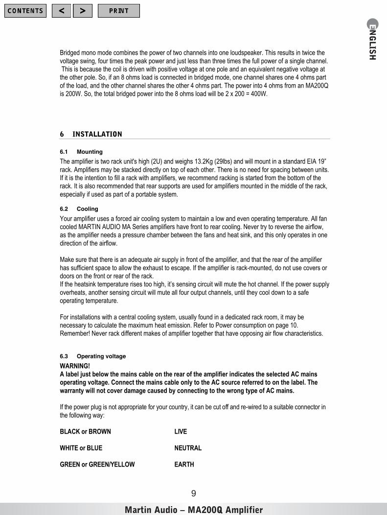
5.4.5 Bridge mono mode features
Martin Audio – MA200Q Amplifier
EN
GLISH
9
Bridged mono mode combines the power of two channels into one loudspeaker. This results in twice the
voltage swing, four times the peak power and just less than three times the full power of a single channel. This is because the coil is driven with positive voltage at one pole and an equivalent negative voltage atthe other pole. So, if an 8 ohms load is connected in bridged mode, one channel shares one 4 ohms part
of the load, and the other channel shares the other 4 ohms part. The power into 4 ohms from an MA200Qis 200W. So, the total bridged power into the 8 ohms load will be 2 x 200 = 400W.
6 INSTALLATION
6.1 Mounting
The amplifier is two rack unit's high (2U) and weighs 13.2Kg (29lbs) and will mount in a standard EIA 19”
rack. Amplifiers may be stacked directly on top of each other. There is no need for spacing between units.If it is the intention to fill a rack with amplifiers, we recommend racking is started from the bottom of therack. It is also recommended that rear supports are used for amplifiers mounted in the middle of the rack,
especially if used as part of a portable system.
6.2 Cooling
Your amplifier uses a forced air cooling system to maintain a low and even operating temperature. All fancooled MARTIN AUDIO MA Series amplifiers have front to rear cooling. Never try to reverse the airflow,as the amplifier needs a pressure chamber between the fans and heat sink, and this only operates in one
direction of the airflow.
Make sure that there is an adequate air supply in front of the amplifier, and that the rear of the amplifier
has sufficient space to allow the exhaust to escape. If the amplifier is rack-mounted, do not use covers ordoors on the front or rear of the rack.If the heatsink temperature rises too high, it’s sensing circuit will mute the hot channel. If the power supply
overheats, another sensing circuit will mute all four output channels, until they cool down to a safeoperating temperature.
For installations with a central cooling system, usually found in a dedicated rack room, it may benecessary to calculate the maximum heat emission. Refer to Power consumption on page 10.Remember! Never rack different makes of amplifier together that have opposing air flow characteristics.
6.3 Operating voltage
WARNING!A label just below the mains cable on the rear of the amplifier indicates the selected AC mainsoperating voltage. Connect the mains cable only to the AC source referred to on the label. The
warranty will not cover damage caused by connecting to the wrong type of AC mains.
If th e p ow er plug is n ot ap pr op r ia te fo r yo u r co u ntry , it ca n b e cu t o ff an d re - wire d to a s uita b le c on n ec to r in
the follow in g w ay :
B LA CK or B RO W N LIVE
W HITE or B LU E N EU TR AL
G REEN or G REEN/YELLO W EAR TH
Martin Audio – MA200Q Amplifier
EN
GLISH
10
O nc e co n ne cte d to a su ita ble AC su pp ly, the amplifier c a n be star te d w ith the p o we r s witc h. Wh en yo up ow er u p the amplifier it tak es a co u ple of se co n ds to s elf c he ck ( this is kn ow n a s the " so ft sta rt" or "s lo w
s ta rt" s eq ue n ce ), th e fa n s th en blow at h ig h s pe e d be fo r e go ing into " id le" . Th e fou r b otto m g re e n LED’s the n illumin a te to s ho w the a mp lifie r is op e ra tio na l.
6.4 Grounding
The re is n o g ro un d lift s witc h o r te r mina l o n th is amplifier . The s ign al gr ou nd is a lwa ys floa tin g (lifted ), with r es pe ct to c h as sis g ro un d v ia a gr ou n d lift re sis to r. If a p o te ntia l d iffer en ce ab ov e 0 .6 V is de tec te d b etwe e n
s ig na l g ro un d a nd c h as sis e ar th , a s h or t cir cu it is a uto ma tic ally in tr od u ce d be twe en th e tw o , en s ur in ge le ctric al p r otec tio n. If o th er eq uip me nt o r a mp lifie rs with in a sy s te m s ho uld d ev elo p an e lec tr ica l fa u lt to e ar th , the ma in s fu s e on th at e q uipme nt s ho u ld r u ptur e d ue to this a utoma tic sy s te m a llow in g a n e ar th
c ur re nt to flow for pr ote ctio n p ur po s es .If ho we v er y o u wish to p e rman en tly c o nn ec t the s ign al g r ou nd to c ha s sis e ar th , c on ne c t th e XLR -c on ne cto r’s s he ll lu g to pin 1. In th e in te r es t o f sa fe ty ne v er d is c on ne c t th e e ar th pin on th e mains c a ble.
To co mp ly with CE a p pr ov a l (r ad io in ter fe re n ce ), th er e is an AC main s filte r. Th is filter n e ed s the c ha s sisg ro un d for r e fe re nc e , oth er wise a cu r re nt lo op is for me d v ia th e sig na l g ro un d.N ev er disc onnec t (lift ) t he mains sa f et y ea r th.
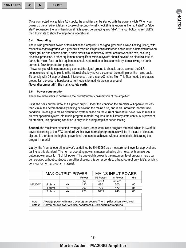
6.5 Power consumption
There are three ways to determine the power/current consumption of the amplifier:
First, the peak current draw at full power output. Under this condition the amplifier will operate for lessthan 2 minutes before thermally limiting or blowing the mains fuse, and is an unrealistic ‘normal’ use
condition. To design a mains distribution system based on the current draw at full power would result inan over specified system. No music program material requires the full steady state continuous power ofan amplifier, this operating condition is only valid during amplifier bench testing.
Second, the maximum expected average current under worst case program material, which is 1/3 of fullpower according to the FTC-standard. At this level normal program music will be in a state of constant
clip and is therefore the highest power level that can be achieved without completely obliterating theprogram material.
Lastly, the "normal operating power", as defined by EN 60065 as a measurement level for approval andtesting to this standard. The normal operating power is measured using pink noise, with an averageoutput power equal to 1/8 of full power. The one-eighth power is the maximum level program music can
be re-played without continuous amplifier clipping, this corresponds to a headroom of only 9dB's, which isvery low for normal program material.
Power 1/3 Power 1/8 Power Idle
[W] note 1 note 2
MA200Q 8 ohms 4x 130 480 300 85
4 ohms 4x 200 720 470 85
2 ohms 4x 270 1065 740 85
note 1 Average power with music as program source. The amplifier driven to clip level.
note 2 Normal music power with 9dB headroom, IEC standard power rating.
MAX OUTPUT POWER MAINS INPUT POWER

Martin Audio – MA200Q Amplifier
EN
GLISH
11
6.5.1 Calculation
The current draw can be calculated by dividing the mains input power by the mains voltage.We recommend that you design the power distribution for at least the required current at 1/8 power, or 1/3
power for heavy-duty demands such as concert touring and Industrial music etc.
The heat power can be calculated as following:If a headroom figure of at least 5dB (1/3 full power) is used with a 4 ohms load on all four channels of theamplifier.The 1/3 power per channel is then; 200 / 3 = 67 watts, and total output power is; 4 x 67 = 267
watts.The mains power consumption from the chart above is 720 watts.
The heat power produced is the difference between the power consumption and output power;720 - 267 = 453 watts total for the amplifier.
MA200Q HEAT POWER
1/3 POWER 1/8 POWER 1/3 POWER 1/8 POWER 1/3 POWER 1/8 POWER
WATTS Kcal/hour BTU/hour
8 Ohm 307 235 260 200 1050 800
4 Ohm 453 370 390 320 1550 1260
2 Ohm 705 605 610 520 2410 2060
1/3 Power level = Average power with music as programme material (continuous clipping)1/8 Power level = Normal operating power with music as programme material (occasional clipping)
7 CONNECTIONS
7.1 Input connections
7.1.1 Balanced inputs
The Inp u t co n ne ctor s a re N eu tr ik co mb o jac ks an d inc or po r ate a n XL R a nd _" (6.3mm) jack. They area ctiv e b alan c ed a nd wire d a s be low :
PIN 1 G RO UN D/SHIEL D PIN 2 H OT ( +) PIN 3 C OL D (- )

Martin Audio – MA200Q Amplifier
EN
GLISH
12
230-240V 50-60Hz
1/ 4 “XLR
3 Neg Ring 2 Pos TipPin 1 Scrn Sleeve
Must be grounded
Le g
dirB/k
niD
+C
Fixed gain 32 dB
LC
+Bkni L
B+
Ae gdirB
/kni
CH.D CH.C INPUTS CH.B CH.A
The Neutrik Combo jack is wired in parallel with the XLR.
TIP H OTR IN G C OL DSLEEVE SHIEL D/G RO UN D
Th e inp ut imped anc e is hig h eno ugh ( 20K oh ms
ba la nce d) to allow ” daisy- ch ain ing ”, or mu ltiple p ar allelin pu t c onn ec tio ns. The hea dr oom of the inp ut circu its isalso high en oug h to acc ept the max imum outpu t leve l
fr om virtu ally any low- lev el signa l sou rce . Balanc ed sign als ar e les s s en sitive to AC h um an d r ad ioin te rfe ren ce . The so urc e imp eda nce s hou ld be le ss
th an 1Ko hms to a void hig h fre que ncy loss es in lo ngsign al cab le s.
7.1.2 Unbalanced inputs
To co nn e ct a n u nb ala nc ed so ur ce , c on n ec t pin 3 ( r in g on TR S jac k) to the sh ie ld of th e co nn e ctor . If yo u
lea ve o n e pin d is co n ne cte d, y ou will lo se 6 d B’s in le ve l.A b ette r meth od o f c on ne c ting u n ba la n ce d so u rc es is s ho w n in be lo w. Th is is s imila r to th e c on ne c tion fo rb alan ce d lin e s, b ut pin 3 is co n ne cte d to th e sh ield at th e s ou rc e. Th e h um a nd no is e r ejec tio n for the ca ble
is eq uiv alen t to th a t of a ba la n ce d lin e. To min imize h u m in th e au d io , u se b ala nc ed in pu ts wh en e ve rp os sible .
Unbalanced line connection Balanced line with unbalanced equipment
7.2 Connecting loudspeakers
L ou ds pe a ke r c on ne ction s a re mad e v ia th e tw o N eu tr ik NL 4FC Spe ak on co nn e ctor s. Th e Spe ak on c on ne cto r is de sign e d fo r h ig h p ow er lo ud sp e ak er us e an d mee ts all w or ld w id e sa fety r eq uire men ts .
C on ne ction s.The Speakons are wired:
Channels A, B output connector
Pin +1, Pin –1 = Output APin +2, Pin –2 = Output B
Channels C, D output connectorPin +1, Pin –1 = Output C
Pin +2, Pin –2 = Output D

Martin Audio – MA200Q Amplifier
EN
GLISH
13
When outputs A and B, or C and D are bridged, the loudspeaker is connected to +1 and -2 of theconnector see diagram below.
Looking at the rear of the amplifier the right hand Speakon has both channel A and B outputs, the lefthand Speakon channels C and D. This configuration is useful for bridging and bi-amp operation (see
bridged mono operation on page7).
chA
chB
Channel A and B (or C and D) into oneSpeakon. . (Quad or Bi-amp)
Bridged mono
Never connect either output terminal to ground or to some other output or input terminal (seewarnings in chapter 1)For normal four-channel operation, connect each loudspeaker load across the output’s positive and
negative terminals. Pay attention to loudspeaker polarity; loudspeakers connected out of polaritydegrade sound quality.Keep the loudspeaker cables as short as possible and use good quality stranded cable. Do not use
shielded wire, such as microphone or guitar cable. Remember that the speaker cable reduces the powerof the amplifier in two ways:It increases the load impedance and introduces resistive power losses.
WARNING: To prevent electric shock, do not operate the amplifier with any of theloudspeaker cable conductors exposed.
8 OPERATION
8.1 Operation precautions
• Make sure that the power switch is set to “OFF ” before connecting any input or output oroperating the switches on rear panel. See pages 9 about installation.
• Make sure that the AC mains voltage is correct and is the same as the one printed on the rearpanel of the amplifier. See pages 9 and 10, about operating voltage and power consumption.
• Make sure that the switches on the rear panel for the different operating modes and the clip-limiter switches are in the correct position. See page 7 about operating modes and page 14 aboutclip limiters.
• It is always a good idea to turn down the gain controls during power-up, to prevent speakerdamage in case a high signal is present at the input.
Martin Audio – MA200Q Amplifier
EN
GLISH
14
8.2 Powering up – Soft start
W he n yo u p ow e r up th e amp lifier it ta ke s a c ou ple o f se c on ds to s elf-c he c k. This is k no wn a s the "s oft- s ta rt" o r "s lo w -s ta r t" s eq u en ce . The fa ns th en b lo w a t h ig h sp e ed b e fo re g o in g into "id le " a nd the fo ur bo ttom
g re en L ED’s illumin a te to s ho w the a mplifie r is o pe ra tio na l.
8.3 Input attenuators
The fou r inp u t le ve l a tte nu ator s o n the fro n t pa n el a dju st th e sign a l le v el for th eir r es pe c tive amplifier c ha nn el’s in all mo d es o f o pe ra tio n. Th ey a r e ca lib ra te d in d B' s to he lp th e se tting up o f a ctiv e lou ds p ea ke r s ys te ms .
In br id g ed mo de , bo th le v el a tte nu ato rs mus t b e in th e s ame p os itio n , so th at th e lo u ds pe ak e r lo a d will be s ha re d e qu ally be tw e en th e ch an n els.
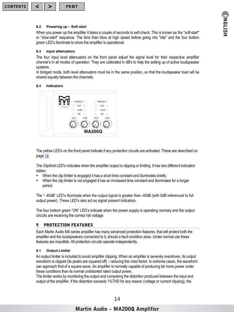
8.4 Indicators
-20-40
-80
-12-16
-3-1
0dB
-5-7-10
-16-12
-80-40
-20 -3
dB 0-1
-10 -7-5
-8 0-40
0dB
-12-16
-7
-3-1
-5-10
dB 0-80-40 -1
-20-16
-12 -10 -7-5-3
CH.A CH.B CH.C CH.D
PROTECT
CLIP
-40dB
ON
MA200Q
PROTECT
CLIP
-40dB
ON
The y ellow L ED' s on th e fro nt p a ne l ind ic ate if a ny p ro tec tio n circ u its a re a ctiva te d . Th es e a re de sc rib ed o n
p ag e 1 4.
The C lip/limit L ED' s ind ic ate s wh e n th e a mp lifie r ou tpu t is clip p in g o r limitin g. It h as tw o d iffe re n t in d ic atio n
s ta te s:• W he n th e c lip limite r is en ga ge d it h as a s h or t time co n stan t a nd illu min ates b r ie fly .• W he n th e c lip limite r is no t en g ag ed it h as an in cr ea se d time c on sta nt a n d illu min ate s fo r a lon g er
p er io d.
The “- 40dB” LED’s illuminate when the output signal is greater than -40dB (with 0dB referenced to full
output power). These LED’s also act as signal present indicators.
The four bottom green “ON” LED’s indicate when the power supply is operating normaly and the output
circuits are receiving the correct rail voltage.
9 PROTECTION FEATURES
Eac h Ma r tin Aud io MA s er ies a mp lifie r h as ma ny a d va nc ed pr ote ctio n fea tu r es , th a t will pr ote ct b o th the
a mp lifie r an d the lo ud sp e ak er s c on ne c te d to it, s ho uld a fau lt co nd ition ar is e. Un de r n or ma l u se th es efea tu re s a re in au dib le . All p ro tec tio n circ u its o pe ra te in de p en de ntly.
9.1 Output Limiter
An ou tp u t limiter is inc lud ed to a vo id amplifier clip pin g. W h en a n a mp lifie r is se ve r ely ov e rd riv en , its o utp utw av efor m is c lipp ed (its pe ak s a re s q ua re d o ff) – r ed uc ing th e cr es t fac tor . In ex tr e me c as e s, th e wa ve for m
c an a pp r oa ch th at o f a s q ua re w a ve . An amplifier is n or mally ca pa ble o f p ro du cin g fa r mor e p ow er un de rthe se c o nd ition s th a n its n or ma l u nd istor te d r ate d ou tp u t po w er .The limite r w or ks b y mon ito ring th e o utpu t a nd c o mp ar in g the distor tio n p ro du ce d b etw ee n th e inp u t an d
o utpu t o f th e a mp lifie r. If the disto rtio n e xc ee d s 1%TH D for an y re a so n ( vo ltag e o r c ur re nt clip p in g) , the
Martin Audio – MA200Q Amplifier
EN
GLISH
15
limiter re du c es the in pu t s ig na l p ro p or tion a lly. No te th at, if th e s ig na l is dis to rte d or c lip pe d b efor e it r ea ch es
the a mp lifie r , th e c lip limiter will no t be ac tiv ated .
U nd er n o rmal op er ation th e clip limiter is ina ud ible. Th e limiter c a n be tu rn ed “O n” or “ Off” by pr es sin g th e
r elev an t c lip limit sw itc h. ( 3 s ee p a ge 5 )Some ma n ufac tur er s o f lo u ds pe ak e r pr o ce ss or s d o n ot r ec o mmen d the u s e of clip limite r s in a mplifier s, a s itc an e ffe ct th e tr ac k in g o f th e p ro ce s so r' s limite rs .
If th e a mp lifie r is be in g u se d w itho u t an y e xter n al limiting , Mar tin Aud io r ec omme n d le a ving th e clip limiter ss witc he d " ON " ( bu tto n de p re ss ed ) .
9.2 Thermal protection
W he n th e a mp lifie r is dr ive n ve r y ha r d in to a lo w imp ed a nc e loa d, th e co o ling fa ns w ill r un at h igh s pe e d. Ifthe se o p er ating c on d itio n s co ntinu e, th e Pr o te ct in dica tor (s ) w ill illumina te in dica tin g th a t th e a mp lifie r is
a bo ut to g o into th e rmal sh utdo w n.
After five s e co nd s the a mplifie r w ill g o in to th e rmal p r otec t b y mu tin g the inp u t sig na l. Afte r 1 5- 20 s e co nd s
the a mp lifie r w ill h av e c oo le d d ow n e no ug h for th e amplifier to c ome o ut of s hu tdo wn an d op e ra te as n or ma l. If th e lo ad co nd ition s r emain u nc ha n ge d the the r ma l p ro te ction w ill b e r e - initiate d. Th er ma lp ro te ction o c cu rs w h en th e h ea ts in k temp er atur e r ea c he s 90 ° C .
9.3 VHF protection
If a signal of more than 12kHz, at full power is detected, which lasts for more than five seconds, the VHFprotection mutes the input signal. (This is indicated on the front panel (4) by the LED labelled Protect).After five seconds the outputs will un-mute and return to normal operation, unless the output signal has
remained unchanged, in which case the VHF protection will re-initiate.
9.4 Short circuit protection
All Martin Audio MA Series amplifiers are completely short circuit protected. The protection circuit permitsvery high peak currents, but still holds the output devices within the safe operating area. If a sh o rt c irc uit ismaintain ed , the c ha n ne l a ffec te d w ill e ve ntu ally go into a th er ma l p ro te c t cy cle u ntil th e s ho rt circ uit h as
b ee n re mov ed .
9.5 AC mains voltage protection
If the AC mains voltage is outside the operational window (over or under voltage), the power supply will
automatically shut down. When the mains voltage is above the minimum start voltage and below itsmaximum operating voltage the amplifier will restart.
The four green ”ON” LED’s indicate when the power supply is operating correctly.
9.6 DC protection
The re a r e tw o typ es of D C p ro te c tion :• Fus es o n the su pp ly br an c he s of ea ch ch an ne l.• D C cr ow b ar p r otec tio n th a t sh or ts th e o utpu t if mor e th a n 10 vo lts D C is be in g d etec ted o n the
o utpu ts . Both the se circ u its co me in to effe c t on c e a DC le ve l is de tec te d o n eithe r c ha nn el.
Martin Audio – MA200Q Amplifier
EN
GLISH
16
10 MAINTENANCE
Under normal use the amplifier should provide years of trouble-free service. The only maintenancerequired by the user is to clean the front grille periodically.In some extreme cases it may be necessary for authorized service personnel to clean the inside of the
amplifier. These conditions usually occur after prolonged use, e.g. in environments using "cracked- oil"smoke machines.If you are using your amplifier for heavy-duty use i.e. concert touring or industrial music it is
recommended that you have your amplifier serviced every 3 years, purely as a preventative measure.
10.1 Troubleshooting
These are typical things to check if you think your amplifier is faulty
Fault: No output.
If the Signal Present (-40dB) is illuminating a signal is entering the amplifier and the likely cause is anunsecured Speakon loudspeaker connector, or loose termination.Check also that the VHF protection is not activated. If it is, remove possible high frequency oscillations
from the relevant input
Fault: The amplifier goes into thermal protection when driven at low level.
Check that there is no short circuit present at the amplifier's output, e.g. any component in theloudspeaker (this can occur when the loudspeaker coil gets hot).
Fault: The amplifier goes into protection with power indicators off.Check that the AC mains voltage is within the amplifier’s operating range, 130-265V@ 230V, and (65-135V @ 115V). Over/under-voltage protection may have occurred. If the amplifier is connected by
mistake to a 3-phase supply, an internal non-resetable fuse or resistor may have blown. The amplifierthen has to be returned to your supplier for service.
Fault: The amplifier does not respond even after checking above items.In the unlikely event of on a non-user rectifiable fault, return the amplifier to your supplier or an approvedservice centre.
Martin Audio cannot be held responsible for damage or injury as a result of the top cover beingremoved.

Martin Audio – MA200Q Amplifier
EN
GLISH
17
11 WARRANTY
General
The MA200Q Power amplifier is warranted to be free from defects in components and factory
workmanship under normal use and service, for a period of three years from the date of original purchase.During this warranty period MARTIN AUDIO LTD or it's nominated agents, will undertake to repair, or atit's discretion, replace this product at no charge to it's owner, when failing to perform as specified,
providing the unit is returned undamaged, in it's original packaging, shipping prepaid, to the factory,distributor or authorised service facility.
This warranty shall be null and void, if the product is subjected to:1) Repair work or alteration by persons other than those authorised by MARTIN AUDIO LTD
or it's agents.
2) Shipping accidents, act of god, war, civil insurrection, misuse, abuse, operation with incorrect AC
voltage, operation with faulty associated equipment, exposure to inclement weather conditions andnormal wear and tear. Units on which the serial number has been removed or defaced will not beeligible for warranty service.
3) MARTIN AUDIO LTD shall not be responsible for any incidental or consequential damages, withrespect to the products warranted.
MARTIN AUDIO LTD reserve the right to make changes or improvements in design or manufacturing,without assuming any obligation to change or improve products previously manufactured.
This warranty is exclusive and no other warranty is expressed or implied.This warranty does not effect your statutory rights.
InternationalPlease contact your supplier for this information, as rights and disclaimers may vary from country to
country.
Technical assistance and services
If your Martin Audio product needs repair, contact your Martin Audio dealer or distributor, or contactMartin Audio to obtain the location of the nearest dealer or distributor.Telephone: +44 (0) 1494 535312
Fax: +44 (0) 1494 438669E mail: [email protected]
Martin Audio – MA200Q Amplifier
EN
GLISH
18
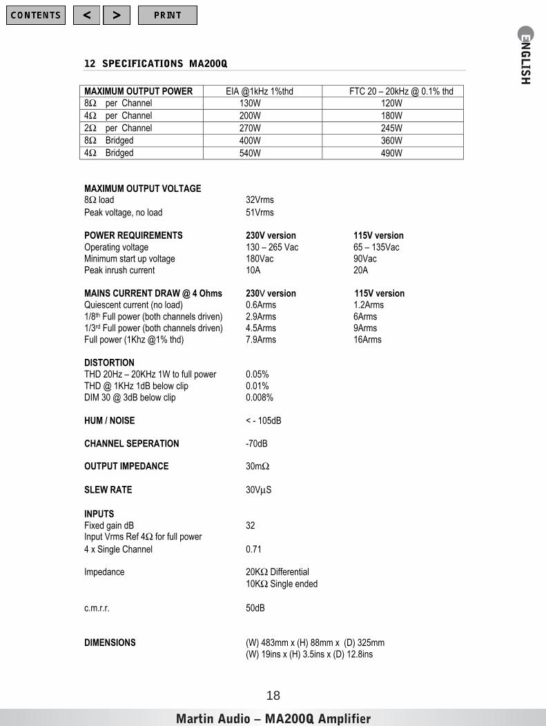
12 SPECIFICATIONS MA200Q
MAXIMUM OUTPUT POWER EIA @1kHz 1%thd FTC 20 – 20kHz @ 0.1% thd
8Ω per Channel 130W 120W4Ω per Channel 200W 180W2Ω per Channel 270W 245W8Ω Bridged 400W 360W4Ω Bridged 540W 490W
MAXIMUM OUTPUT VOLTAGE8Ω load 32VrmsPeak voltage, no load 51Vrms
POWER REQUIREMENTS 230V version 115V versionOperating voltage 130 – 265 Vac 65 – 135VacMinimum start up voltage 180Vac 90VacPeak inrush current 10A 20A
MAINS CURRENT DRAW @ 4 Ohms 230V version 115V versionQuiescent current (no load) 0.6Arms 1.2Arms1/8th Full power (both channels driven) 2.9Arms 6Arms1/3rd Full power (both channels driven) 4.5Arms 9ArmsFull power (1Khz @1% thd) 7.9Arms 16Arms
DISTORTIONTHD 20Hz – 20KHz 1W to full power 0.05%THD @ 1KHz 1dB below clip 0.01%DIM 30 @ 3dB below clip 0.008%
HUM / NOISE < - 105dB
CHANNEL SEPERATION -70dB
OUTPUT IMPEDANCE 30mΩ
SLEW RATE 30VµS
INPUTSFixed gain dB 32Input Vrms Ref 4Ω for full power4 x Single Channel 0.71
Impedance 20KΩ Differential10KΩ Single ended
c.m.r.r. 50dB
DIMENSIONS (W) 483mm x (H) 88mm x (D) 325mm(W) 19ins x (H) 3.5ins x (D) 12.8ins

Martin Audio – MA200Q Amplifier
EN
GLISH
19
WEIGHT 13.2Kg (29Ibs)
SHIPPING DIMENSIONS (W) 560mm x (H) 180mm x (D) 500mm(W) 22ins x (H) 7.1ins x (D) 19.7ins
SHIPPING WEIGHT 14.8Kg (32.5lbs)
Front PanelGain controls 4 x 31 Position detentIndicators Protect 4 x Yellow LED’s
Indicators Clip 4 x Red LED’sIndicators Signal Present 4 x Green LED’s
Rear PanelInput Connectors 4 x Neutrik Combo, + 3 pin PhoenixOutput Connectors 2 x Neutrik Speakons
Clip Limiters Push Switch “ON”/ ”OFF” per ChannelInput Link switches A+B, C+D, B+C
Speakonö and Combø jack, are registered Trademarks of Neutrik AG Liechtenstein.
MA200Q Amplifier
Century Point, Halifax Road, Cressex Business Park, High Wycombe, Buckinghamshire HP12 3SL, England. Telephone: +44 (0)1494 535312 Facsimile: +44 (0)1494 438669
Web: www.martin-audio.com E-mail: [email protected]
The Martin Experience
Please Click here toreturn to main menu
Please Click here tovisit our website

The Martin Experience
ENGLISH
MA200Q Amplifier
User’s Guide