markingmaster en software
DESCRIPTION
Software instructionTRANSCRIPT

Marking Master Professional
Marking software Date: June 2011
Software version 6.120.00

Software manual MarkinMaster Ver. 1.0 engl..doc Page 2 of 124
1 Table of contents
1 TABLE OF CONTENTS 2
2 INTRODUCTION 7
2.1 Preface 7
2.2 Scope of delivery 7 2.2.1 Delivery with copy protection 7 2.2.2 Delivery without copy protection 7
2.3 Limitation of warranty 7 2.3.1 Concerning this manual 8 2.3.2 Symbols 9 2.3.3 Counting symbols 9
2.4 Software licence agreement 10 2.4.1 Licence agreement 10 2.4.2 Definition of terms 10 2.4.3 Copyright 10 2.4.4 Warranty 10 2.4.5 Running time 10
2.5 Service and contact address 11
3 APPLICATIONS 11
4 SYSTEM REQUIREMENTS 12
5 CONNECTING A CONTROLLING COMPUTER TO A MARKING UNIT 12
5.1 Connection to MarkingMaster 12
6 INSTALLATION 13
6.1 Desktop shortcut with MarkingMaster Professional 15
6.2 Create an entry in Autostart file 15
7 USING THE GUI (GRAPHICAL USER INTERFACE) 15
7.1 Starting MarkingMaster Professional software 16
8 FIRST MARKING 17

Software manual MarkinMaster Ver. 1.0 engl..doc Page 3 of 124
9 STRUCTURE OF THE GRAPHICAL USER INTERFACE (GUI) 21
9.1 Structure of drop-down menu 21
9.2 Tool bar 21
9.3 Status bar 22
9.4 Hotkeys 22
10 FILE MANAGEMENT 22
10.1 MDI display management 23
10.2 Create new file 23
10.3 Open existing file 23
10.4 Close current file 23
10.5 Save current file 24
10.6 Save current file as 24
10.7 Import 24
10.8 Export 25
10.9 Import 25
10.10 Export 25
10.11 Mark current file 26
10.12 Last opened files 28
10.13 Menu Windows 29 10.13.1 Windows cascade 29 10.13.2 Windows tile 29 10.13.3 Important notes on working with multiple windows opened 29
10.14 Select/activate opened file 30
10.15 Exit file 30
11 VIEW OF SCREEN 31
11.1 Tool bar 31
11.2 Status bar 31
11.3 Zoom in 32
11.4 Zoom out 32

Software manual MarkinMaster Ver. 1.0 engl..doc Page 4 of 124
11.5 Total view 32
11.6 Raster 0.1mm 33
11.7 Raster 1mm 33
11.8 Current object always in foreground 33
11.9 Display marking sequence 34
11.10 Show graphic backdrop 35
12 OBJECT MANAGEMENT 35
12.1 What is an object? 36
12.2 Selecting an object 36
12.3 Create new object 37 12.3.1 New object is a fixed text 37 12.3.2 New object is a variable 38 12.3.3 New object is imported text line 43
12.4 Modify object 44
12.5 Position object and define marking direction 44
12.6 Determine object size 45
12.7 Determine object direction 48 12.7.1 Circular marking 49 12.7.2 Important notes on object positioning 50 12.7.3 Examples 51
12.8 Delete object 68
12.9 Duplicate object 68
12.10 Protect object 70
12.11 Object Select font 71
12.12 Marking sequence of objects 72 12.12.1 Move object forward in marking sequence 73 12.12.2 Move object backwards in marking sequence 73
12.13 Align Object group 74 12.13.1 Left-justified 74 12.13.2 Right-justified 74 12.13.3 Centred 74 12.13.4 Align upwards 74 12.13.5 Align downwards /unten ausrichten 74
12.14 Select Text file for import 74

Software manual MarkinMaster Ver. 1.0 engl..doc Page 5 of 124
12.15 Graphic - Import 75
12.16 Start graphic converter 77
12.17 Use selected graphic as graphic backdrop 79
12.18 Problems during graphic import 79
13 PARAMETER 80
13.1 Basic Settings 80 13.1.1 Positioning speed 81 13.1.2 Processing speed 81 13.1.3 Response time tool 81 13.1.4 Distance of standard font 81 13.1.5 Standard character height 81 13.1.6 Standard character width 81 13.1.7 Font standard / mirrored writing 81
13.2 Starting position 82
13.3 Positioning 83
13.4 Operating mode (XY / Rotary device)) 85
13.5 XY-mode 85
13.6 Rotary device 86
13.7 Layout info text 89
13.8 Settings electric marking head 90 13.8.1 Settings options 91 13.8.2 Definition of settings 91
14 EXTRAS 92
14.1 Communication TCP/IP 92 14.1.1 Table 92 14.1.2 TCP/IP active 93 14.1.3 Port number 93 14.1.4 Create a variable by filling via TCP/IP (optional) 93 14.1.5 Display variable 96
14.2 Object layer 97
14.3 Table 97
14.4 Current layer 97
15 DATAMATRIX CODE 98
15.1 DataMatrix Code 98 15.1.1 Important notes on DMC 98

Software manual MarkinMaster Ver. 1.0 engl..doc Page 6 of 124
15.1.2 Create DataMatrix Code from fixed text 99 15.1.3 Create DMC from objects 100
15.2 DataMatrixCode Options 106
15.3 Define object size 107
16 HELP AND HINTS 108
16.1 Notes on improving the marking quality 108 16.1.1 General 108 16.1.2 Pneumatic marking head 108 16.1.3 Electric marking head 108
16.2 Hints on how to increase the marking speed 109
16.3 Graphic backdrop 110
17 FONTS 112
17.1 OCR-font 112
17.2 Din 1451 112
17.3 DotMatrix Font 113
18 ERROR MESSAGES 114
18.1 Home point not reached 114
18.2 Marking window exceeded 114
18.3 System not ready to receive 114
18.4 Invalid Port number 114
18.5 No access to HPGL graphic 118
18.6 No access to font 118
19 ADDENDUM 119 19.1.1 Checkbox/Radiobox 119 19.1.2 GUI (Graphical User Interface) 120 19.1.3 HPGL format 120 19.1.4 OCR 121
19.2 Table of abbreviations 122
19.3 Overview of tables 123
20 CONTACT 124

Software manual MarkinMaster Ver. 1.0 engl..doc Page 7 of 124
2 Introduction
2.1 Preface You have decided to receive Marking Master professional with your Marking Mas-ter hardware. It’s a comfortable and effective software tool for the CNC-controlled marking technology. Marking Master professional was especially designed for the controlling of Marking Master systems. It has been focused on simple and self-explanatory software structure. Nevertheless, in case of any questions regarding the operation, you can contact our team of experts at any time. Your Richter team.
2.2 Scope of delivery
2.2.1 Delivery with copy protection
• 1 pc. Software CD (incl. manual Marking Master Professional)
• 1 pc. Dongle
• 1 pc. Data link cable
• 1 pc. Manual
2.2.2 Delivery without copy protection
• 1 pc. Software CD (incl. manual Marking Master Professional)
• 1 pc. Data link cable
• 1 pc. Manual
2.3 Limitation of warranty The company Richter reserves the right to modify the information and specifications of this manual without advanced notice. In order to get to know if modifications are executed you can contact the company Richter. The company Richter does not make responsibility for coincidental, special or conse-quential damage of any kind (incl. all damages occurring out of lost profits), due to or in relation to this manual or any contained information, not even if the company Rich-ter referred to the possibility of such damage, had / must have had knowledge of it. The contained information in this manual is confidential and is the property of the company Richter and / or their OEM’s.

Software manual MarkinMaster Ver. 1.0 engl..doc Page 8 of 124
Restriction of liability We do not take on any liability on for the correct content of this manual. The data of technical progress can be modified without any notice. Despite all care we cannot exclude any kind of fail ures and/or errors in print-ing. We would highly appreciate it if you helped us to i mprove this manual. So in case you notice an error and have an idea to improv e this manual please con-tact us.
2.3.1 Concerning this manual The present texts and illustrations in this manual conduce to the explanation of the correct use of this system.
2.3.1.1 Style of lettering The different font styles which are used in this manual have the following meaning: „Text“(normal): Descriptive, informative text „Text“(normal, underlined): Subheadings „Text“(Text bold) : Emphases important text passages „Text“(Text bold / italic) : Query to a description in the appendix

Software manual MarkinMaster Ver. 1.0 engl..doc Page 9 of 124
2.3.2 Symbols The symbols which were used in that manual have got the following meaning:
Read the operating manual Important hint
2.3.3 Counting symbols
Numerations
Behaviour guidelines
Danger
OK
Warning of a certain danger! Warning of a source of danger! There is a explanation how you have to behave to reduce the danger to a minimum e.g. wearing protective clothes. .

Software manual MarkinMaster Ver. 1.0 engl..doc Page 10 of 124
2.4 Software licence agreement
The concerned programmes are exclusively licensed by the company Richter for the end users and only for them by considering the following terms. You agree to these terms by accepting and using these programmes. This is a legal agreement between the company Richter and the user.
2.4.1 Licence agreement The company Richter agrees to grant you an unexclusive licence of Marking Master professional software / firmware (herein to as the „programme“) by considering the terms of this licence.
2.4.2 Definition of terms The term Software relates to a computer programme that is saved on CD, hard disk or any other data medium and will be loaded into the memory of a PC for execution. The term Firmware relates to a computer programme that is saved into a semicon-ductor memory (ROM, PROM, EEPROM, FLASH, etc.) and is an essential part of a computer memory.
2.4.3 Copyright The programme and the manual are the property of the company Richter. The pro-gramme contains business secrets and legally protected properties of the company Richter. You’re only allowed to create copies for archiving safety purposes. Neither the programme nor the manual must not be modified or translated without the written permission of the company Richter.
2.4.4 Warranty The warranty for the corresponding programme is part of the Standard Sales Terms of the company Richter.
2.4.5 Running time This licence is unlimited in terms of time. However it expires instantly if any condition of the licence agreement is not fulfilled. By using this programme you confirm that you have read the licence agreement and have accepted all terms. This agreement is complete and validates all other agreements which apply

Software manual MarkinMaster Ver. 1.0 engl..doc Page 11 of 124
2.5 Service and contact address
Joachim Richter e.K., Systeme und Maschinen Erlenhöhe 3-5 - Industriegebiet D-66871 Konken Germany Switchboard +49(0)6384 9228- 0 Fax +49(0)6384 9228-77 Hotline +49(0)6384 9228-55 E-mail [email protected] Internet http://www.jr-richter.de/
3 Applications Marking Master Professional has been especially developed for the control of the Marking Master machines. Marking Master Professional enables a fast and efficient creation of writings (fixed terms, date, time, sequential numbering, even company logos which have been de-signed with CAD), which are positioned, lined up and modified in their size. Marking Master professional has a user-friendly graphical user interface (GUI) and guarantees a fast and easy start for the user. The anticipated marking result is visible on the screen for the user at any time.

Software manual MarkinMaster Ver. 1.0 engl..doc Page 12 of 124
4 System requirements
PC- System (minimum requirements) CPU Pentium from 400 MHz or equivalent AMD CPU Memory 32 MB RAM Interface USB Hard drive 2 GB Operating system Windows 2000 /Windows XP/Vista Input device Mouse / trackball, touch screen, keyboard
Monitor min. VGA resolution Table 1 Overview System requirements If the system does not meet the requirements, a satisfactory working performance cannot be achieved. The communication between PC and marking system is done via a special USB ca-ble that’s delivered along with the machine.
5 Connecting a controlling computer to a marking unit Before installing the Marking Master Professional software, you have to create a con-nection between the PC and the marking unit itself.
5.1 Connection to Marking Master
• Now connect the USB port of your PC to the USB port of the Marking Master with the provided interface cable.
• The USB cable may not be longer than 3m. If cable has been extended the
signal is weaker and this can lead to troubles with the marking unit.
• Connect the Marking Master to a mains supply and switch on the machine.
• Normally you can install the USB ports on your own now. Should this be not possible please execute the installation programme EASYSYNC. You can find it on the provided CD.
Software manual MarkinMaster Ver. 1.0 engl..doc Page 13 of 124
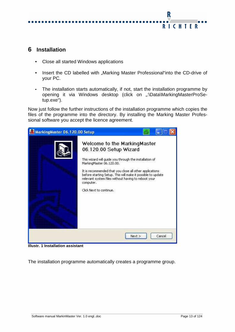
6 Installation
• Close all started Windows applications
• Insert the CD labelled with „Marking Master Professional“into the CD-drive of your PC.
• The installation starts automatically, if not, start the installation programme by
opening it via Windows desktop (click on „:\Data\MarkingMasterProSe-tup.exe“).
Now just follow the further instructions of the installation programme which copies the files of the programme into the directory. By installing the Marking Master Profes-sional software you accept the licence agreement.
Illustr. 1 Installation assistant The installation programme automatically creates a programme group.
Software manual MarkinMaster Ver. 1.0 engl..doc Page 14 of 124
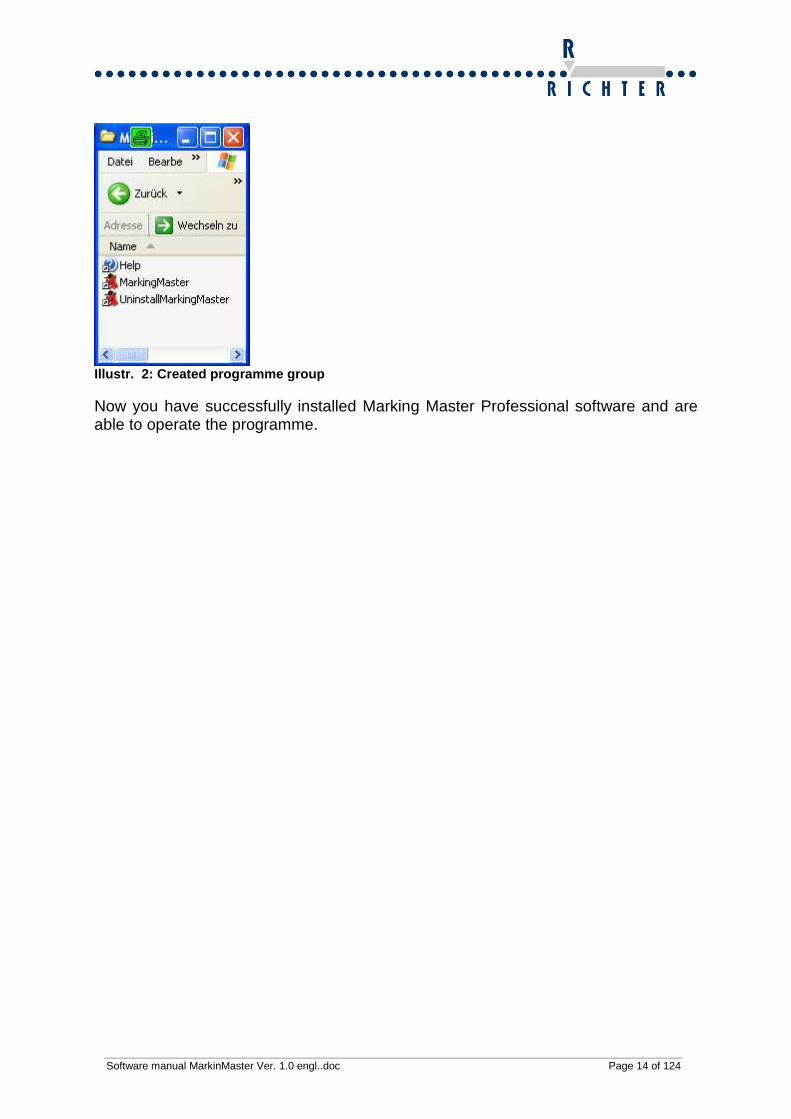
Illustr. 2: Created programme group Now you have successfully installed Marking Master Professional software and are able to operate the programme.

Software manual MarkinMaster Ver. 1.0 engl..doc Page 15 of 124
6.1 Desktop shortcut with Marking Master Profession al In order to start the Marking Master Professional for easy and quick daily use, you can create a link on the Windows desktop. Right click on a free field of the desktop. Select “Link” in the menu “New” which is popping up. Navigate to the pre-selected directory and double-click on MarkingMaster.exe.
Illustr. 3: Select path to MarkingMaster.exe
Illustr. 4: Created shortcut
6.2 Create an entry in Auto start file If you need Marking Master daily, you can create an entry in the Start Up folder of your Windows operating system. So the software will be started by every booting or by every login.
• Click on Start � Programmes � Start Up (double click)
• Open the folder, in which the software was installed, via Windows Explorer
• Please right click on MarkingMasterPro.exe and keep on pressing the button.
• Now drag and drop the link in the Start Up folder and click on ‘Create shortcut here’.
7 Using the GUI (graphical user interface) The operation of Marking Master professional is executed according to Windows standards. Basically, the operation is possible with or without mouse support. How-ever, it is recommended to use a mouse or a trackball for efficient working. In order to facilitate the operation without mouse you can reach the most important pro-gramme functions via the keys (F1 -.F12) and hotkeys.

Software manual MarkinMaster Ver. 1.0 engl..doc Page 16 of 124
7.1 Starting Marking Master Professional software If a shortcut has been created in the Auto start file, then Marking Master Professional will be automatically started when logging onto Windows or by starting the PC. In case a shortcut has already been created on your desktop via MarkingMaster-Pro.exe, please double click on it in order to start the programme. Otherwise you are able to start the programme via „Start � Programmes � MarkingMasterPro.
Important ! Please switch MarkingMaster off, before starting the software. If required please close the software, switch the device on and restart the software. Only this guarantees the USB ports to be properly recognized.

Software manual MarkinMaster Ver. 1.0 engl..doc Page 17 of 124
8 First marking First create an object, so it can be marked. Select the menu point “Object /Create new/Text“.
An entry field opens up. Enter the desired text in the field and confirm your entry with the button “OK”.
After that a positioning window pops up. In this window you can enter the coordinates of the object. If the coordinates are not found, the object can also be positioned (TEACH IN). Push the button “Teach in”, so object can be positioned.

Software manual MarkinMaster Ver. 1.0 engl..doc Page 18 of 124
Via the buttons Y-Plus/Y-Minus/X-Plus/X-Minus the position can be found (TEACH IN). By push in the respective button the device traverses by the step value selected. The current position is output in the fields between these buttons. When using a Z or A-axis, also these coordinates must be defined (TEACH IN). After the device has been positioned properly (TEACH IN), please confirm the position with the button “OK”.
Illustr. 5 Teach In dialogue After confirming it the summary of the coordinates will be displayed. If they are alls correct, exit the window by pressing „OK“.

Software manual MarkinMaster Ver. 1.0 engl..doc Page 19 of 124
Then choose the menu point „Mark/File“.
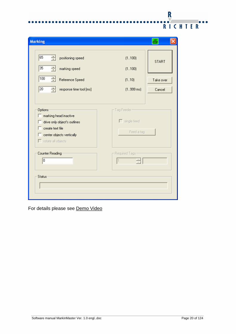
The marking dialogue will be opened. It is possible to enter more parameters here. For further details to those parameters please see the following chapter. The marking will be started by pushing the button “START”.
Software manual MarkinMaster Ver. 1.0 engl..doc Page 20 of 124
For details please see Demo Video

Software manual MarkinMaster Ver. 1.0 engl..doc Page 21 of 124
9 Structure of the graphical user interface (GUI)
9.1 Structure of drop-down menu The drop-down menus are created according to Windows standard. Via these menus you can open all programme functions.
Illustr. 6: Main menu bar
Illustr. 7: Example: Drop-down menu “Object”
9.2 Tool bar The tool bar enables you to reach the most important functions directly by one mouse click. If you drag the cursor of the mouse over the icons in the tool bar, and the func-tions will be displayed with a yellow coloured info tag (Tool tip).
Illustr. 8: Tool bar left
Illustr. 9: Tool bar right The icons of the tool bar and their functions are described in the chapters 7 – 13.

Software manual MarkinMaster Ver. 1.0 engl..doc Page 22 of 124
9.3 Status bar The status bar is positioned in the lowest part of Marking Master Professional and will be updated with the most important operative parameters:
• Information to the currently selected object (XY-position, height, width, size factor)
• Positioning raster currently valid (0.1mm / 1.0mm)
• Operating parameter (final switch, free home point, XY-mode / rotary device
active)
Illustr. 10: Status bar (shortened for illustration)
9.4 Hotkeys Hotkeys are key combinations or single keys for fast execution of operative steps. They are described in the following chapters 7-13.
10 File Management Marking Master professional offers the possibility to save objects (text, wild-card/placeholders and graphics) together as a file. Such a file is also called layout. The created files can be re-opened on request and are available at any time. The number of files is only limited by the hard disk capacity. You can give file names with up to 128 characters as it is basic Windows standard. Variables such as date, will automatically updated when reopening the marking lay-out. The last number marked will be saved when it is a counter variable.
Important: All basic settings (speed, machine type, operating mode, etc.) also will be saved during the saving process of marking files and will be restored after loading of the files.

Software manual MarkinMaster Ver. 1.0 engl..doc Page 23 of 124
10.1 MDI display management Marking Master Professional supports the simultaneous work with several files in separate windows, thus it is standard for 32bit Windows applications. This concept is called MDI (Multiple Document Interface).
10.2 Create new file Drop-down menu File � new Hotkey Ctrl + N
Icon
New files, that you create, get a standard name with a sequential number, given by Marking Master professional. In order to exactly identify your files you can give them individual names by saving them for the first time.
10.3 Open existing file Drop-down menu File � Open… Hotkey Ctrl + O
Icon
In order to open a file, select the corresponding marking layout from the list which is organized in alphabetical order. All saved setting will be automatically restored. For frequently occurring marking tasks the time consumption is limited to a minimum this way.
10.4 Close current file Drop-down menu File � Close Hotkey Ctrl + C
The file currently opened will be closed. If you have modified the file after the last saving procedure, an automatic security check comes up asking for the modifications to be saved or not.

Software manual MarkinMaster Ver. 1.0 engl..doc Page 24 of 124
10.5 Save current file Drop-down menu File � Save Hotkey Ctrl + S
Icon
When saving a file all parameters set will be saved. All basic settings, as e.g. speed and mode of operation, will be saved permanently - also the entered texts and linked graphics.
10.6 Save current file as Drop-down menu File � Save As… Hotkey None
Illustr. 10: File �Save as The current file will be saved with a new, free choice name.
10.7 Import
Drop-down menu File � Import Hotkey None
It is possible to load layouts from the format ‘Programme-File-Richter’ *.pdr with Marking Master Professional.
Software manual MarkinMaster Ver. 1.0 engl..doc Page 25 of 124
10.8 Export
Drop-down menu File � Export Hotkeys None
Here you can convert the*.mkt layout into *.pdr format
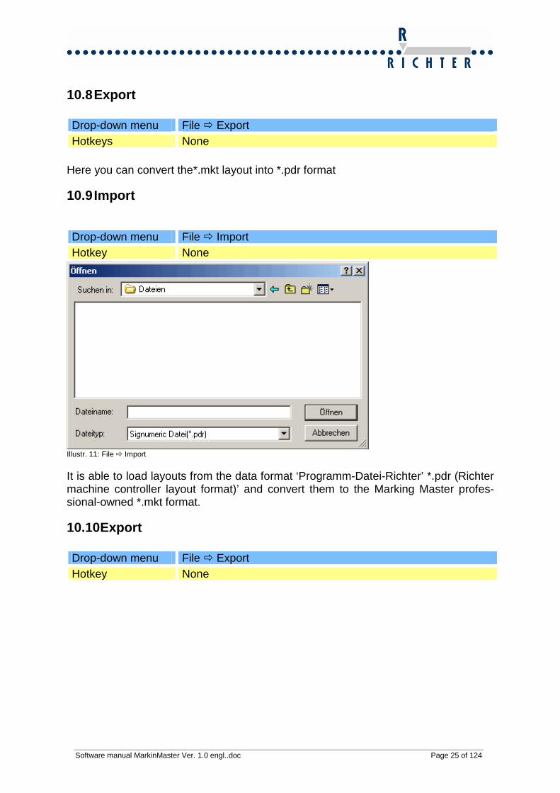
10.9 Import
Drop-down menu File � Import Hotkey None
Illustr. 11: File � Import It is able to load layouts from the data format ‘Programm-Datei-Richter’ *.pdr (Richter machine controller layout format)’ and convert them to the Marking Master profes-sional-owned *.mkt format.
10.10 Export
Drop-down menu File � Export Hotkey None

Software manual MarkinMaster Ver. 1.0 engl..doc Page 26 of 124
Illustr.12: File � Export It is able to load layouts from the data format ‘Programme-File-Richter’ *.pdr (Richter machine controller layout format)’ and convert them to the Marking Master profes-sional-owned *.mkt format.
10.11 Mark current file
Drop-down menu File � Mark Hotkey Ctrl + B or F3
Icon
Software manual MarkinMaster Ver. 1.0 engl..doc Page 27 of 124
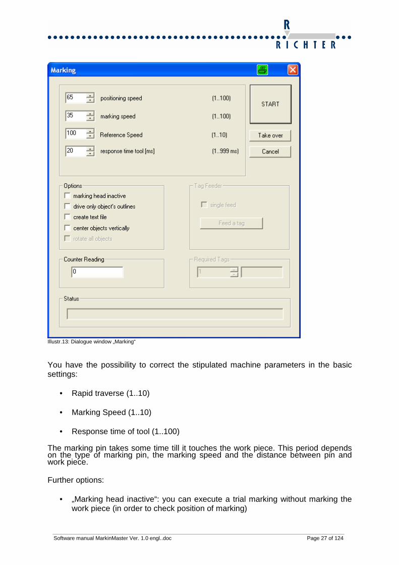
Illustr.13: Dialogue window „Marking“ You have the possibility to correct the stipulated machine parameters in the basic settings:
• Rapid traverse (1..10)
• Marking Speed (1..10)
• Response time of tool (1..100)
The marking pin takes some time till it touches the work piece. This period depends on the type of marking pin, the marking speed and the distance between pin and work piece. Further options:
• „Marking head inactive“: you can execute a trial marking without marking the work piece (in order to check position of marking)

Software manual MarkinMaster Ver. 1.0 engl..doc Page 28 of 124
• „Only check object contours“: you can check the marking area by tracing the objects contours
• „Create text file“you can create a text file in which the marking text is pasted. If
a file has been selected which exists already, Marking Master Professional at-taches the new files to the ones already existing.
Click on ‘Start’ to start marking.
10.12 Last opened files
Drop-down menu File � area between marking and finishing Window �lower part of the drop-down menu
Hotkey None The previously opened files can be reopened very easily. The numbering is scaled down from currently opened layout to the first opened layout. This function helps you to save time, if you mainly working with a small amount of layouts that frequently change.

Software manual MarkinMaster Ver. 1.0 engl..doc Page 29 of 124
10.13 Menu Windows
10.13.1 Windows cascade
Illustr. 14 Windows cascade
10.13.2 Windows tile
Illustr.15 Windows tile
10.13.3 Important notes on working with multiple wi ndows opened All modification relate to the active window. If the marking process is started, all marking files positioned in the window will be sent to Marking Master.
Software manual MarkinMaster Ver. 1.0 engl..doc Page 30 of 124
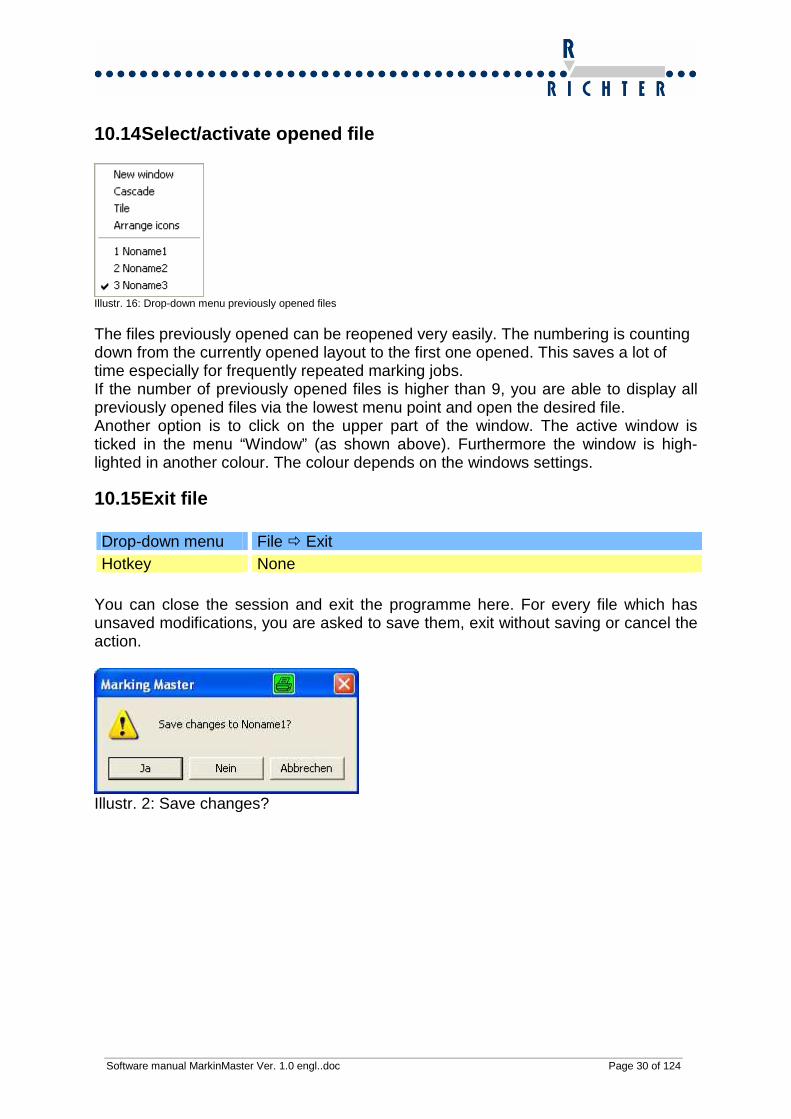
10.14 Select/activate opened file
Illustr. 16: Drop-down menu previously opened files The files previously opened can be reopened very easily. The numbering is counting down from the currently opened layout to the first one opened. This saves a lot of time especially for frequently repeated marking jobs. If the number of previously opened files is higher than 9, you are able to display all previously opened files via the lowest menu point and open the desired file. Another option is to click on the upper part of the window. The active window is ticked in the menu “Window” (as shown above). Furthermore the window is high-lighted in another colour. The colour depends on the windows settings.
10.15 Exit file
Drop-down menu File � Exit Hotkey None
You can close the session and exit the programme here. For every file which has unsaved modifications, you are asked to save them, exit without saving or cancel the action.
Illustr. 2: Save changes?

Software manual MarkinMaster Ver. 1.0 engl..doc Page 31 of 124
11 View of screen
Illustr. 17: Drop-down menu View In this menu you are able to set up the view of the GUI. Here you can fade in and out the tool bar.
11.1 Tool bar Drop-down menu View � Tool bar Hotkey None
Here you can fade in and out the Tool bar.
11.2 Status bar Drop-down menu View � Status bar Hotkey None
Here you can fade in and out the Status bar.

Software manual MarkinMaster Ver. 1.0 engl..doc Page 32 of 124
11.3 Zoom in
Drop-down menu View � Zoom in Hotkey Page Up
Icon
The view of the marking window will be scaled up. The scale of the coordinates sys-tem is adjusted automatically
11.4 Zoom out
Drop-down menu View � Zoom Out Hotkey Page Down
Icon
The view of the marking window will be scaled down. The scale of the coordinates system is adjusted automatically
11.5 Total view
Drop-down menu View � Total View Hotkey None Icon
The complete marking area will be displayed on the screen. The scale of the coordi-nates system is adjusted automatically.

Software manual MarkinMaster Ver. 1.0 engl..doc Page 33 of 124
11.6 Raster 0.1mm
Drop-down menu View� Raster 0.1 mm Hotkey Alt + 0
Icon
All selected objects will be shifted by 0.1mm per keystroke via the arrow keys.
11.7 Raster 1mm Drop-down menu View� Raster 1 mm Hotkey Alt + 1
Icon
All selected objects will be shifted by 1.0mm per keystroke via the arrow keys.
11.8 Current object always in foreground Drop-down menu View� Current object always in foreground Hotkey None
If several objects overlap on the screen, the current object is always displayed in the foreground and highlighted in dark grey.

Software manual MarkinMaster Ver. 1.0 engl..doc Page 34 of 124
11.9 Display marking sequence Drop-down menu View � Show marking sequence Hotkey None
Illustr. 3: Show object sequence
Illustr. 18: Show Object sequence The current ranking in the object sequence will be displayed in the right upper corner above each object. Marking without option „Mark backwards“
In order to accelerate the marking it is possible to choose the option „Mark backwards“ for object 2.

Software manual MarkinMaster Ver. 1.0 engl..doc Page 35 of 124
Marking with option „Mark backwards“
11.10 Show graphic backdrop Drop-down menu View � Show graphic backdrop Hotkey None
In case you have selected a graphic backdrop, you can fade it in and out.
12 Object management
Illustr. 19: Drop-down menu Object

Software manual MarkinMaster Ver. 1.0 engl..doc Page 36 of 124
12.1 What is an object? An object is a fixed text, a wildcard/placeholder for date / time, a counter, a DataMa-trixCode or a bar code. Even integrated graphics are called objects. You can assign various characteristics, as e.g. position, size and direction to an ob-ject. An object can be positioned at a various location on the marking surface.
12.2 Selecting an object Drop-down menu No entry Hotkey + / - on the number block
Icon Click on object to choose or
The selection of the next object is based on the marking sequence. This is done via the keys + or - or by clicking onto the icon. If several objects are positioned on the working surface, all actions which are available in the object management relate to the current object. The current object is highlighted in green colour. The inactive objects appear in black (for text and graphics) or dark blue colour (vari-ables) on the screen. It is possible to simultaneously select several objects. In order to do this you need to keep on pressing the left mouse key to frame the desired objects from the upper left above the object group.

Software manual MarkinMaster Ver. 1.0 engl..doc Page 37 of 124
12.3 Create new object
12.3.1 New object is a fixed text
Drop-down menu Object� Create new�Text
Hotkey Alt + T or F2
Icon
Illustr.20: Object is a fixed text If an object is created as fixed text, a dialogue window appears in which you can en-ter the desired order of characters. With any marking process the fixed text will be worked off as a consistent order of characters.

Software manual MarkinMaster Ver. 1.0 engl..doc Page 38 of 124
12.3.2 New object is a variable
Drop-down menu Object � Create new�Variable
Hotkey Alt + V or F3
Icon
Illustr. 21: Settings for variables Its current value will be assigned to a variable in the moment of marking. There are various formats for date, calendar week, time, sequential numberings, year counter and shift codings available.

Software manual MarkinMaster Ver. 1.0 engl..doc Page 39 of 124
12.3.2.1 Date and time functions Create a date variable
Please enter the desired format in the highlighted window and confirm with “OK“. Abbrev. Meaning Abbr. Meaning %a Abbrev. Name of the week-
day %M Minute, decimal (00-59)
%A Name of the weekday %n Month in letter big (A - )
%b Abbrev. Name of the month %S Second, decimal (00-59)
%B Full name of month %U Week with Sunday in first, deci-mal (00-53)
%c Date and time in regional formatting
%w Weekday with Sunday in first, decimal (0-6)
%d Day of the month, decimal (01-31)
%W Week with Monday in first, deci-mal (00-53)
%H Hour in 24h format, decimal (00-23)
%x Date in regional formatting
%I Hour in 12h format, decimal (01-12)
%X Time in regional formatting
%j Day of the year, decimal(001-366)
%y Year without century, decimal (00-99)
%l Year in letter big () %Y Year with century, decimal
%L Year in letter big () %z; %Z Donation of the actual time zone
%m Month, decimal (01-12) %% Percent sign
The shown abbreviations can be nested arbitrary and replenished with plain text.

Software manual MarkinMaster Ver. 1.0 engl..doc Page 40 of 124
12.3.2.2 Sequential numbering (counter function 1) Create a counter variable
Illustr. 1 Variables Counter parameter
Illustr. 4: Sequential numbering Start value
• This value is marked during the first marking process
Software manual MarkinMaster Ver. 1.0 engl..doc Page 41 of 124
End value
• After reaching this value the marking will be finished with the message “Counter has reached its end value”.
Step size
• The step size is indicated with these parameters.
Example: Start value = 1 Step size = 1 During 1. marking the number 1 is marked. During 2. marking the number 2 is marked. During 3. marking the number 3 is marked. Start value = 1 Step size = 2 During 1. marking the number 1 is marked. During 2. marking the number 3 is marked. During 3. marking the number 5 is marked.
Leading Zeros
• If this option is chosen, the programme completes the number with zeros. The number of leading zeros is defined by the entered end value.
Example: Start value 1 End value 10 Marking with optional leading zeros 01 Marking without optional leading zeros 1 Start value 1 End value 100 Marking with optional leading zeros 001 Marking without optional leading zeros 1

Software manual MarkinMaster Ver. 1.0 engl..doc Page 42 of 124
12.3.2.3 Annual counter total (Counter function 2) You can reset the ‘Annual counter total’ by typing in a password.
12.3.2.4 Shift marking
Illustr. 5: Settings shift marking In the field “Time” the starting time of the shift can be entered in the above format. You can enter the name or the initials of the operator into the field ”Marking symbol” on the right hand side,

Software manual MarkinMaster Ver. 1.0 engl..doc Page 43 of 124
12.3.3 New object is imported text line
Drop-down menu Object � Create new�Import text line
Hotkey None
Icon
Illustr. 6: Dialogue to select one or more text lin es A *.txt- file can be selected in the file browser. The path to the file can also be en-tered manually.
• Insert fixed text – There can be a *.txt file selected in a file browser. The path to the file can also be entered manually. The object which relates to the text can be named. This is shown on the working surface, however it does not have influence of the marking result. Only a single line can be inserted from the selected text file. Herewith you can adjust which line and how many char-acters are to be inserted from the line. Also you can name a description for the object, which is showed, if no data is assigned, also there the number of the adjusted line is shown in brackets after the description
• Continuous text - Several lines can be imported sequentially from the selected
text file. Herewith you can enter the start and the finish line, also you can choose the column, in which the data is read; after the marking sequence has finished, the next line is being imported .

Software manual MarkinMaster Ver. 1.0 engl..doc Page 44 of 124
12.4 Modify object
Drop-down menu Object � Modify
Hotkey F4
Icon Double-click and
MarkingMaster Professional recognizes the type of object and opens the corresponding dia-logue window.
• Fixed text or DataMatrix Code: The current character sequence can be changed in the dialogue window popping up.
• Variable: The variable can be reformatted in the dialogue window popping up
12.5 Position object and define marking directio n
Drop-down menu Object � Position
Hotkey Alt+P or arrow keys � � � �
Icon
Illustr. 22: Dialogue window „Text position“ The selected object can be variously positioned on the working surface:
• Click on object, then drag and drop.
• Enter the established values into the dialogue window „Text position“.

Software manual MarkinMaster Ver. 1.0 engl..doc Page 45 of 124
• Via TeachIN you are able to travel to the position of the object and adopt the posi-
tioned value for the object in the manual mode.
• Centred – here the object can be positioned in the centre
• Mark backwards – tick here, if you want to mark the object backwards.
12.6 Determine object size
Drop-down menu Object � Define size
Hotkey Alt+S
Icon
• Marking size, width and character pitch can be adjusted for text-based objects.
Standard settings
Illustr. 23 Modified character size and width

Software manual MarkinMaster Ver. 1.0 engl..doc Page 46 of 124
Modified character pitch The pitch between the characters changes.

Software manual MarkinMaster Ver. 1.0 engl..doc Page 47 of 124
Modify size of a special character or graphic The size of a graphic can only be modified on a percentage basis.
Illustr.24:Size factor

Software manual MarkinMaster Ver. 1.0 engl..doc Page 48 of 124
12.7 Determine object direction
Drop-down menu Object � Define object direction
Hotkey Alt+R
Icon
Illustr. 25: Define object size The following positions are possible:
• Horizontal • horizontally turned • vertically bottom-up
• vertically top down • circular (see chapter 12.7.1)

Software manual MarkinMaster Ver. 1.0 engl..doc Page 49 of 124
• free angle
• centred – the position will be kept as the centre of the object.
• mark backwards – saving time when marking multiple lines (Option:enable /
disable this function).
• mark Yes / No – Standard: ‘Yes’ is ticked, tick ‘No’, so the object will not be marked.
• insert into DMC – tick here in order to add a text to the created datamatrix
code next; There is only one content of the datamatrix code generated per file, which is continuously extending.
When marking several objects it is possible to save time by combining it with the modifiable sequence of objects.
12.7.1 Circular marking
Drop-down menu Object � Define direction Hotkey Alt+R Activate circular
Icon
then click on the point „Circular“.
You have got the possibility to mark circular texts on even surfaces of round work-pieces in an easy and efficient way (e.g. brake discs).
Object Object
Object Object
Forward
Backward
Object sequence 1 2
3 4

Software manual MarkinMaster Ver. 1.0 engl..doc Page 50 of 124
Parameter:
• Inside radius of circle
• Start angle of character order
• Start angle / final angle or fixed character distance (angle)
• End angle of character order (select start / final angle)
• Distance of angle in degrees per character (fixed character separation (angle))
• Standard or inverted:
o Standard: the font will be placed on the outer radius; it is legible on the inside.
o Inverted: the font will be placed on the inner side of the radius; it is legi-ble on the outside.
12.7.2 Important notes on object positioning Do not exceed maximum size of the marking window when positioning the objects. The positions of objects must be positioned in the menu point Position/object and you have to define the marking direction.

Software manual MarkinMaster Ver. 1.0 engl..doc Page 51 of 124
If the object is not in the desired position after positioning it, you can change this via drag and drop.
12.7.3 Examples
12.7.3.1 Horizontal
12.7.3.2 Horizontally turned
Starting point
Starting point

Software manual MarkinMaster Ver. 1.0 engl..doc Page 52 of 124
12.7.3.3 Vertically up
Starting point

Software manual MarkinMaster Ver. 1.0 engl..doc Page 53 of 124
12.7.3.4 Vertically -down
Starting point

Software manual MarkinMaster Ver. 1.0 engl..doc Page 54 of 124
12.7.3.5 Free angle – Example 1
Starting point

Software manual MarkinMaster Ver. 1.0 engl..doc Page 55 of 124
12.7.3.6 Free angle – Example 2
Software manual MarkinMaster Ver. 1.0 engl..doc Page 56 of 124
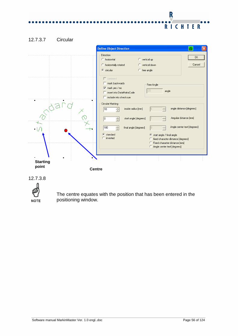
12.7.3.7 Circular
12.7.3.8
The centre equates with the position that has been entered in the positioning window.
Centre
Starting point

Software manual MarkinMaster Ver. 1.0 engl..doc Page 57 of 124
12.7.3.9 Parameter – Circular marking This function enables you to mark circular texts on the circumference on round parts in an easy and efficient way. Parameter: •Position X of the centre •Position Y of the centre Start angle
End angle Centre of cir cle (values X and Y)
• Inside radius of circle • Character height • Character width • Start angle of character sequence • End angle of character sequence (only applicable if start/end angle is selected) • Distance of angle per character (only applicable if a fixed character pitch has been
selected) • Either start angle and end angle or start angle and angle distance per character. • Standard (bottom of character next to centre of circle)
Inverted (top of character next to centre of circle) • Circular text
Circular marking parameterized via start and end angle (0°-180°)
180°
90°
0°
270°

Software manual MarkinMaster Ver. 1.0 engl..doc Page 58 of 124
In order to parameterize the object circularly via start and end angle, the Radiobox ‘Start/end angle’ must be activated.
Illustr. 26 Circular marking Start/end angle
If a circle is created the inside radius is relevant. Inside radius The radius relates to te lower edge of the characters (inside radius, see illustration below, blue arrow). The marking window consists of inside radius AND character size (green arrow).

Software manual MarkinMaster Ver. 1.0 engl..doc Page 59 of 124
Circular marking parameterized via start and end angle (270°-360°) In order to parameterize the object circularly via start and end angle, the Radiobox ‘Start/end angle’ must be activated.

Software manual MarkinMaster Ver. 1.0 engl..doc Page 60 of 124

Software manual MarkinMaster Ver. 1.0 engl..doc Page 61 of 124
Circular marking parameterized via fixed character pitch (6°) In order to parameterize the object circularly via start and end angle, the Radiobox ‘Fixed character pitch’ must be activated.
The start angle defines the starting position. The end angle will be automatically cal-culated by means of marking width and fixed angle distance. It is not required to en-ter the value of the end angle.

Software manual MarkinMaster Ver. 1.0 engl..doc Page 62 of 124
Circular marking parameterized via fixed character pitch (15°) In order to parameterize the object circularly via start and end angle, the Radiobox ‘Fixed character pitch’ must be activated.
When changing the angle distance, the end angle will be automatically changed. If the radius of object is changed, then the pitch between each character is changed as well. By modifying the radius the distance per degree of angle is getting larger.
Angle distance

Software manual MarkinMaster Ver. 1.0 engl..doc Page 63 of 124
Circular marking parameterized via fixed character pitch (15°) and modified radius
By changing the radius the character pitch and the end angle will be modified as well.
Software manual MarkinMaster Ver. 1.0 engl..doc Page 64 of 124
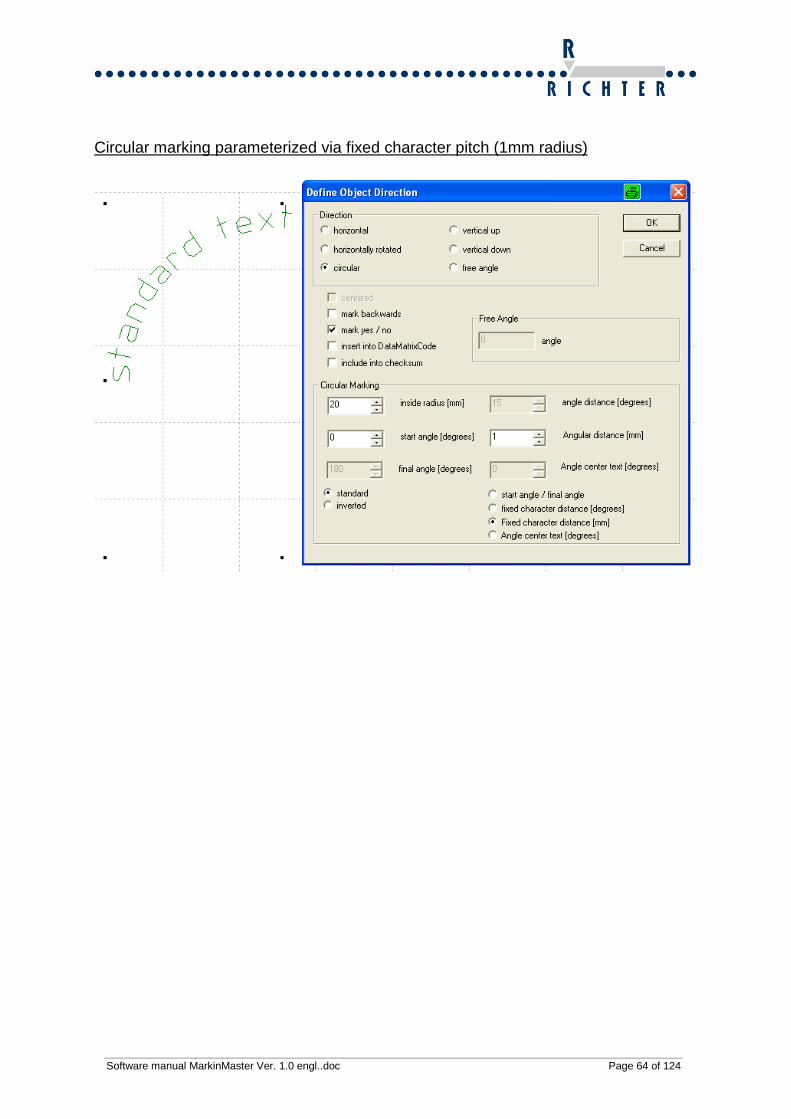
Circular marking parameterized via fixed character pitch (1mm radius)
Software manual MarkinMaster Ver. 1.0 engl..doc Page 65 of 124
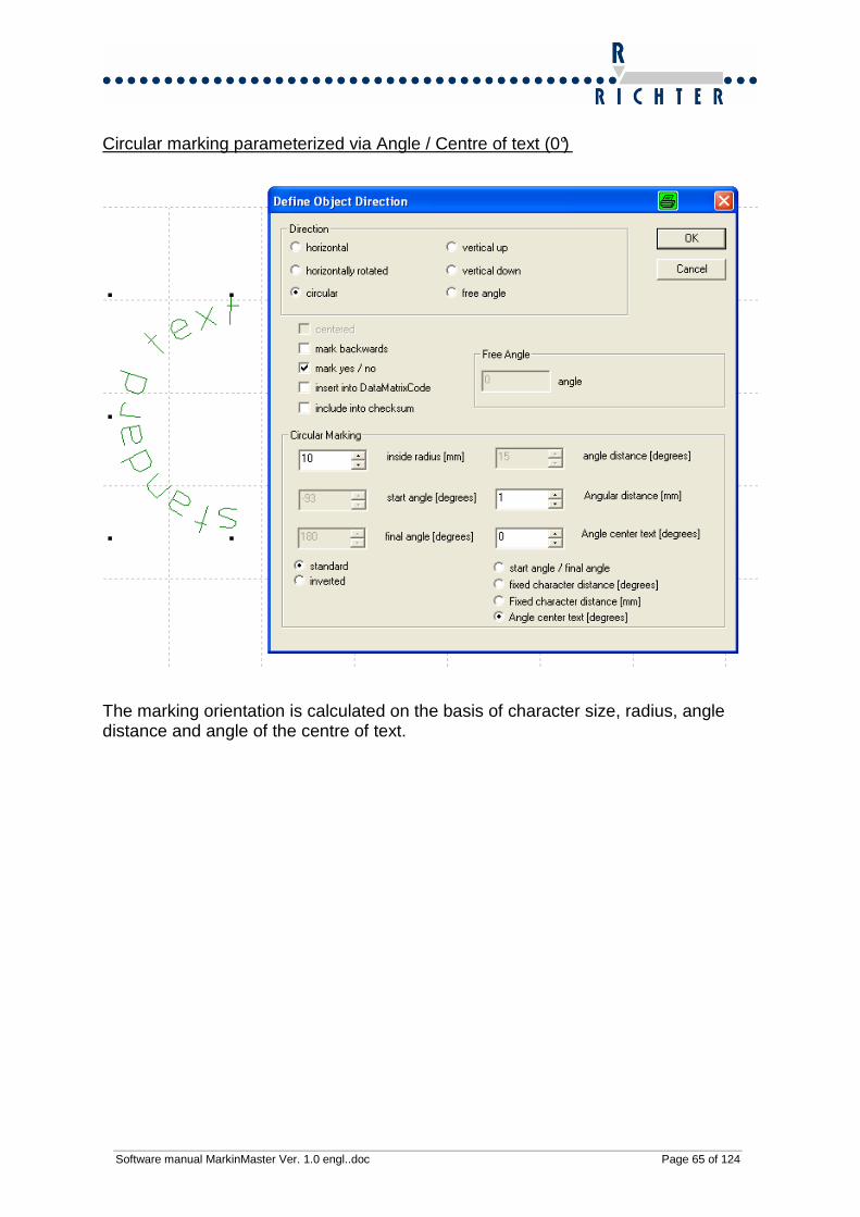
Circular marking parameterized via Angle / Centre of text (0°)
The marking orientation is calculated on the basis of character size, radius, angle distance and angle of the centre of text.
Software manual MarkinMaster Ver. 1.0 engl..doc Page 66 of 124
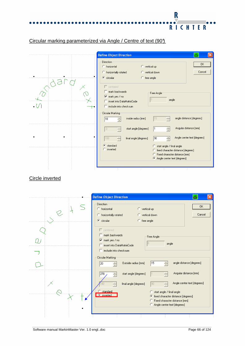
Circular marking parameterized via Angle / Centre of text (90°)
Circle inverted

Software manual MarkinMaster Ver. 1.0 engl..doc Page 67 of 124
If an inverted circle is created the outside radius is relevant. Outside radius The radius relates to the lower edge of the characters (outside radius, see illustration below, blue arrow). The marking window size equates with the radius.

Software manual MarkinMaster Ver. 1.0 engl..doc Page 68 of 124
12.8 Delete object
Drop-down menu Object � Delete
Hotkey DEL
Icon
The current object will be deleted. If several objects have been selected for deletion, they will all be deleted.
12.9 Duplicate object
Drop-down menu Object � Duplicate
Hotkey None

Software manual MarkinMaster Ver. 1.0 engl..doc Page 69 of 124
Illustr.27: Duplicate object The current object will be duplicated. If several objects have been selected, they will all be duplicated. Furthermore the offset values for existing values of X, Y and Z can be entered, in or-der to shift the newly created objects towards their originals.

Software manual MarkinMaster Ver. 1.0 engl..doc Page 70 of 124
12.10 Protect object
Drop-down menu Object � Protect
Hotkey None
Illustr. 28: Protect object
• Full object protection ON: Object will be highlighted in light-grey and cannot be modified.
• Object protection Position On: Object will be highlighted in light-grey, its text
can be modified.
• Object protection OFF: Object is authorized for all object functions.

Software manual MarkinMaster Ver. 1.0 engl..doc Page 71 of 124
12.11 Object Select font
Drop-down menu Object � Select font
Hotkey None
Icon
Function: Object will be displayed and marked in the desired font. Note: The more complex the font is, the longer MarkingMaster takes to complete the marking of object. Mark the desired object. After that select the object…Define font. The window below pops up. Double-click onto the desired font and it will be adopted.
Example Arial font
Example Standard font .

Software manual MarkinMaster Ver. 1.0 engl..doc Page 72 of 124
12.12 Marking sequence of objects It is possible to determine the marking sequence of the text/graphic objects. This se-quence can be adjusted and modified. The current sequence can be found in the menu point „View/Marking sequence“.
Illustr. 29 View Marking sequence - inactive

Software manual MarkinMaster Ver. 1.0 engl..doc Page 73 of 124
12.12.1 Move object forward in marking sequence
Illustr. 30 View Marking sequence – active / Object in marking sequence one step forward
Drop-down menu Object � Object in marking sequence one step forward
Hotkey Ctrl++
The current object will be moved one step forward in the marking sequence.
12.12.2 Move object backwards in marking sequenc e
Drop-down menu Object � Object in marking sequence one step backwards
Hotkey Ctrl+-
The current object will be moved one step backwards in the marking sequence.

Software manual MarkinMaster Ver. 1.0 engl..doc Page 74 of 124
12.13 Align Object group In case you have selected an object group by framing it, you are able to align it via the three functions below:
12.13.1 Left-justified
Drop-down menu Object → Align object group left-justified.
All selected objects will be positioned left-justified. The smallest value X of the object group will be the value X for the whole group.
12.13.2 Right-justified
Drop-down menu Object → Align object group right-justified
All selected objects are positioned right-justified. The largest value X of the object group will be the value X for the whole group (largest value of the right outside edge of an object matters).
12.13.3 Centred
Drop-down menu Object → Align object group centred
All selected objects will be positioned in the centre. All objects will be centred in verti-cal direction (average of values X).
12.13.4 Align upwards
Drop-down menu Object → Align object group upwards
All selected objects will be aligned upwards. All object will be aligned to the highest value Y of an object (upper edge of objects matters).
12.13.5 Align downwards /unten ausrichten
Drop-down menu Object → Align object group downwards
All selected objects will be aligned downwards. All objects will be aligned to the low-est value X of an object (lower edge of objects matters).
12.14 Select Text file for import
Drop-down menu Object � Select text file for import
Hotkey None
Select a text file for the object “Imported text file”.

Software manual MarkinMaster Ver. 1.0 engl..doc Page 75 of 124
12.15 Graphic - Import
Drop-down menu Graphic � Graphic - Import
Hotkey Alt+I
Icon
Illustr.31: HPGL – Import, Select graphic file in *.plt format MarkingMaster Professional offers you the possibility to import graphics and to adjust their size. The following file formats can be processed:
• PlotFiles (*.plt)
• DXF-Files (*.dxf)
• AutoCAD (*.dwg)
• PlotFiles (*.hgl)
Software manual MarkinMaster Ver. 1.0 engl..doc Page 76 of 124
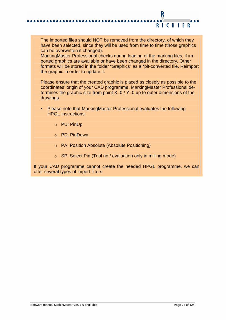
The imported files should NOT be removed from the directory, of which they have been selected, since they will be used from time to time (those graphics can be overwritten if changed). MarkingMaster Professional checks during loading of the marking files, if im-ported graphics are available or have been changed in the directory. Other formats will be stored in the folder “Graphics” as a *plt-converted file. Reimport the graphic in order to update it. Please ensure that the created graphic is placed as closely as possible to the coordinates’ origin of your CAD programme. MarkingMaster Professional de-termines the graphic size from point X=0 / Y=0 up to outer dimensions of the drawings • Please note that MarkingMaster Professional evaluates the following
HPGL-instructions:
o PU: PinUp
o PD: PinDown
o PA: Position Absolute (Absolute Positioning)
o SP: Select Pin (Tool no./ evaluation only in milling mode) If your CAD programme cannot create the needed HPGL programme, we can offer several types of import filters

Software manual MarkinMaster Ver. 1.0 engl..doc Page 77 of 124
12.16 Start graphic converter The graphic converter can be started here: Drop-down menu Graphic � Run graphic converter Hotkey None Icon
Illustr. 32: Graphic converter to convert into *.plt files
With this tool you can convert following file formats into *.plt files:
• AutoCAD(*.dwg)
• DXFFiles(*.dxf)
• PlotFiles(*.plt)
• PlotFiles(*.hgl)

Software manual MarkinMaster Ver. 1.0 engl..doc Page 78 of 124
Illustr. 33:Converter – Conversion process
Illustr. 34: Converter – Properties dialogue
The following properties can be edited for graphics:
• X-min and Y-min equates to Point 0 – this function is advantageous for graph-ics which do not start at 0/0, as the marking starts at point 0/0
• Modify size of graphics - you can enter the factors or in integer mm values.
• Turn graphic - The graphic can be rotated in various, integer degrees
• The minimum vector length can be defined

Software manual MarkinMaster Ver. 1.0 engl..doc Page 79 of 124
12.17 Use selected graphic as graphic backdrop
Drop-down menu Graphic � Use selected graphic as graphic backdrop
Hotkey None
This function offers the possibility to show a graphic backdrop as positioning and ori-entation help without it being edited during marking process. For instance, you can load the contour of a tag as graphic backdrop, in order to use it as a on-screen posi-tioning help for marking every single field.
12.18 Problems during graphic import In case of problems during graphic import, please get in touch with our hotline (see paragraph 1.5 Service and contact address).

Software manual MarkinMaster Ver. 1.0 engl..doc Page 80 of 124
13 Parameter
Illustr. 35: Main menu Parameter
A numerous quantity of parameter which concern the connected machine, can be adjusted here.
13.1 Basic Settings
Drop-down menu Parameter � Basic settings Hotkey None
Illustr. 36: Basic settings

Software manual MarkinMaster Ver. 1.0 engl..doc Page 81 of 124
13.1.1 Positioning speed The positioning speed is the speed with which the machine moves while the marking head is switched off. This is scaled from 1 to 100 (1.100%).
13.1.2 Processing speed The processing speed is the speed with which the machine moves while the marking head is switched on. This is scaled from 1 to 100 (1.100%).
13.1.3 Response time tool Depending on the distance from tip of marking pin to workpiece, you can define the time (1.999ms), the tool takes to make the first dot at the beginning of each line.
Important:
• Large distance to workpiece: high time value
• Small distance to workpiece: low time value You will notice that the time value enormously affects the dynamics of the marking!
13.1.4 Distance of standard font Set up the distance between two single characters for new objects.
13.1.5 Standard character height Set up the standard font size for new objects.
13.1.6 Standard character width Set up the standard font width for new objects.
13.1.7 Font standard / mirrored writing Here you can select between normal and mirrored font.
Software manual MarkinMaster Ver. 1.0 engl..doc Page 82 of 124
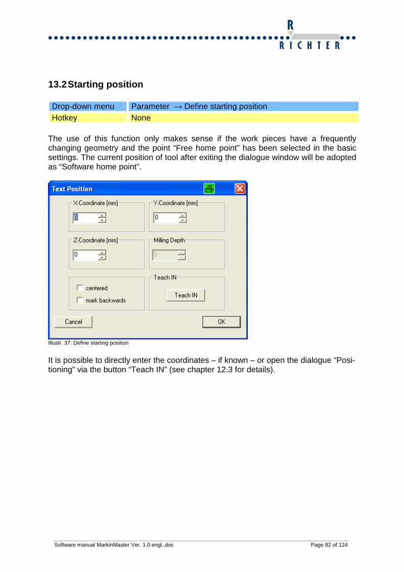
13.2 Starting position
Drop-down menu Parameter → Define starting position Hotkey None
The use of this function only makes sense if the work pieces have a frequently changing geometry and the point “Free home point” has been selected in the basic settings. The current position of tool after exiting the dialogue window will be adopted as “Software home point”.
Illustr. 37: Define starting position
It is possible to directly enter the coordinates – if known – or open the dialogue “Posi-tioning” via the button “Teach IN” (see chapter 12.3 for details).

Software manual MarkinMaster Ver. 1.0 engl..doc Page 83 of 124
13.3 Positioning
Drop-down menu Parameter � Define Home Hotkey F10
Icon
Illustr. 38 Window Positioning
It is possible to traverse the marking system manually in positioning mode. This win-dow is opened, if you have clicked on “TeachIN” before. So you can define the posi-tions of objects, determine a free home point or a starting position in X/Y/Z-mode. The tool can be variously moved by activating the fields X+ / Y+ X- / Y- / Z+ / Z- / Tool ON / Tool OFF. In this dialogue you can adjust the increment of the movement per keystroke:
• 0.1mm • 1.0mm • 10mm
The X-, Y-, Z- and A-axes can be moved, if they are available. Also you can turn the tool ‘ON’ or ‘OFF’.

Software manual MarkinMaster Ver. 1.0 engl..doc Page 84 of 124
You can click on ‘Reference’ every time and the machine moves all axes to their home positions. You can use this dialogue with the mouse by clicking on the button; also you can change the buttons with the arrow / Tab – Shift + Tab keys, and press them by hitting the ‘Space bar’ or the ‘Enter’ key. .

Software manual MarkinMaster Ver. 1.0 engl..doc Page 85 of 124
13.4 Operating mode (XY / Rotary device))
Drop-down menu Parameter � Operating mode (XY / Section apparatus) Hotkey F8 Icon
Illustr. 39: Define operating mode
13.5 XY-mode You are able to mark workpieces in two dimensions in the XY-mode.

Software manual MarkinMaster Ver. 1.0 engl..doc Page 86 of 124
13.6 Rotary device
Illustr. 40: Rotary device
You can mark cylindrical workpieces in this mode. Enter the diameter of the workpiece and the starting position in order to do this. Travel the Y-axis to the centre of the workpiece (above the axis) via TeachIN and to the de-sired X-position. The X-position will only be considered as starting position. Thus it can be driven around obstacles. The Y-position equates with the home point of the A-axis. After marking a travel to home and to the starting position is being executed.

Software manual MarkinMaster Ver. 1.0 engl..doc Page 87 of 124
After that the object can be positioned via TeachIN.
The rotary axis can be moved via the buttons A+ and A-.
13.6.1.1 Marking process The marking systems travels to its starting position.
Y Starting position
Workpiece

Software manual MarkinMaster Ver. 1.0 engl..doc Page 88 of 124
Then marking begins. Instead of the Y-axis the rotary device is moving dur-ing marking process.
The coordinates system is being calculated in direction Y. Basis for this calculation is the entered diameter.
Starting position Y (Window Rotary device)
Entered value of A-Axis
Entered value of X-axis

Software manual MarkinMaster Ver. 1.0 engl..doc Page 89 of 124
13.7 Layout info text
Drop-down menu Parameter � Layout info text
Hotkey None
fig. 7: Layout info text Here you have the possibility to leave a comment with each file, e.g. special advice for the operator. It will be shown before every first marking of a marking sequence.

Software manual MarkinMaster Ver. 1.0 engl..doc Page 90 of 124
13.8 Settings electric marking head
Illustr.41: Parameter settings of electric marking head If you have got a marking system with electric head you can adjust the required pa-rameter here: The ComboBox “Settings” enables a rough setting via “Fine”, “Strong” and “Medium”. These predetermined values have to be adjusted if required. The below factors also have got effects on the marking result:
Angle of marking pin Distance of tip of marking pin to workpiece Material of workpiece (soft plastic – stainless steel) Font and character size (for a small character size (h < 3mm) it is recom-mended to use the setting „Fine“.

Software manual MarkinMaster Ver. 1.0 engl..doc Page 91 of 124
13.8.1 Settings options
• Frequency (10Hz-150Hz) • Depth (1%-70% power) • Com-Port (1 - 255)
You can receive all current parameter from controller and send the values set to the controller.
13.8.2 Definition of settings
13.8.2.1 Frequency This setting has got effects on the impact frequency of the MarkingMaster.
13.8.2.2 Depth This setting has got effects on the depth (power) of the electric marking head.
13.8.2.3 Com-Port It is possible to adjust the respective port for the data transfer to the electric marking head.
13.8.2.4 Send The entered settings will be sent to the marking head via this button.
13.8.2.5 Receive The data can be read from electric marking head via this function.
13.8.2.6 Tool on It is possible to manually switch on the marking via this button and so the settings will be checked.
13.8.2.7 Tool off This button is used for switching the marking head off.

Software manual MarkinMaster Ver. 1.0 engl..doc Page 92 of 124
The settings will be adopted only if those have been sent to the device (button „Send“).
14 Extras
14.1 Communication TCP/IP Drop-down menu Extra → Communication TCP/IP Hotkey None
Illustr.42: Window Communication TCP/IP
14.1.1 Table You can define in this table which object of the layout shall be made available for re-mote marking.
Software manual MarkinMaster Ver. 1.0 engl..doc Page 93 of 124
The following details will be displayed:
• Name – Name of an object – very important for variables.
• Type – Type of object (see chapter 9.3 New object)
• Text – Content of text of an object – very important for variables.
14.1.2 TCP/IP active Tick the check box here in order to activate the remote marking via TCP/IP com-mands.
14.1.3 Port number Select the port number of the TCP/IP communication to be used for remote control.
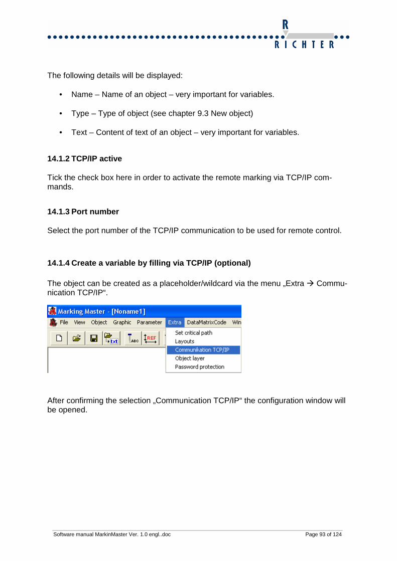
14.1.4 Create a variable by filling via TCP/IP (opt ional) The object can be created as a placeholder/wildcard via the menu „Extra � Commu-nication TCP/IP“.
After confirming the selection „Communication TCP/IP“ the configuration window will be opened.

Software manual MarkinMaster Ver. 1.0 engl..doc Page 94 of 124
The text object must be parameterized here. By clicking onto the name the field will be highlighted (blue colour). By clicking onto “Name “ (Text) again, the name can be changed.
Then change the name to „VARIABLE“. Only use capital letters. After that tick the check box “VARIABLE” and confirm the setting by clicking on “OK”. All objects have
Check box

Software manual MarkinMaster Ver. 1.0 engl..doc Page 95 of 124
to be ticked, otherwise the placeholder/wildcard function will not be released and only the created text can be marked. The name of variable is depending from the application.
If a variable is read via a bar code scanner, for example, the variable must ha-ve the name“BARCODE“. This function is available as an option.

Software manual MarkinMaster Ver. 1.0 engl..doc Page 96 of 124
14.1.5 Display variable ,
Illustr. 43 Display variable content You can display the content of variable via this function. If this function is disabled, only the placeholder/wildcard name will be shown. In that case only VARIABLE would be displayed on the screen.

Software manual MarkinMaster Ver. 1.0 engl..doc Page 97 of 124
14.2 Object layer
Drop-down menu Extra → Object layer Hotkey None
Illustr. 44: Window Object layer
14.3 Table
• Layer – In the first column you can determine the object layer. Click on the de-sired line and click once again here. Now you are able to edit the field “Layer”.
• Type – The object type is displayed here.
• Number – The number of the marking sequence is shown here.
14.4 Current layer Select ‚All’, or ‚Layer 1’, Layer 2’ .. ‚Layer 99’. ‚Layer 0’ always is displayed with the selected layer.

Software manual MarkinMaster Ver. 1.0 engl..doc Page 98 of 124
15 DataMatrix Code You can create a 2D-code (DMC). This can be displayed squared, rectangular or ver-tical.
15.1 DataMatrix Code
Drop-down menu DataMatrix Code � DataMatrix Code Hotkey None Icon
15.1.1 Important notes on DMC The size (number of fields) of a DMC is depending from the number of characters. When reading the DMC by a camera, the size must be specified. In order to analyze the size, please count the dots of one . For a rectangular code you have to count both angles.
Illustr. 45 Square DMC 10x10 Code sizes of a square code 10 10 12 12 14 14 16 16 18 18 20 20 22 22 24 24 26 26 32 32

Software manual MarkinMaster Ver. 1.0 engl..doc Page 99 of 124
Code sizes of a rectangular code 8 18 8 32 12 26 12 36 16 36 16 48
15.1.2 Create DataMatrix Code from fixed text
Illustr. 46: Enter data for DataMatrix Code By means of the RadioBox first select the function „Create DMC from fixed text“. In the field below the RadioBox you can type in the text for the DataMatrix Code to be marked. This entry has to be confirmed with OK. After that the DataMatrix Code ap-pears on the screen.
Software manual MarkinMaster Ver. 1.0 engl..doc Page 100 of 124
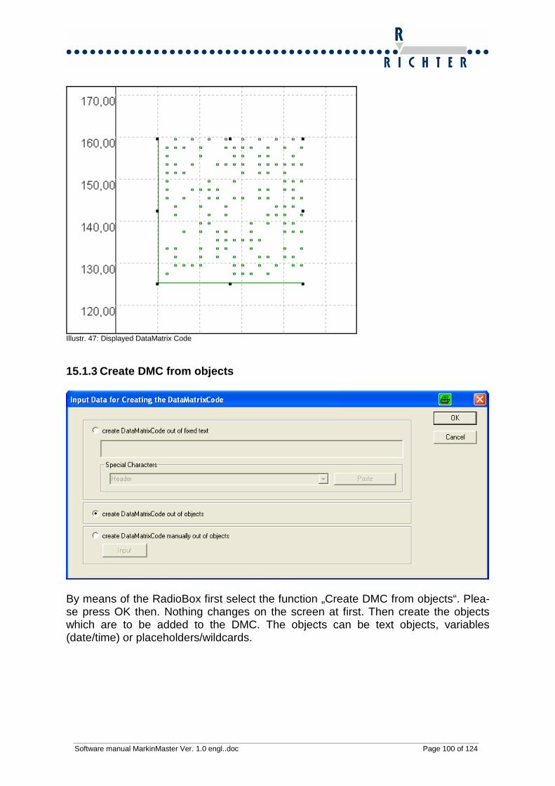
Illustr. 47: Displayed DataMatrix Code
15.1.3 Create DMC from objects
By means of the RadioBox first select the function „Create DMC from objects“. Plea-se press OK then. Nothing changes on the screen at first. Then create the objects which are to be added to the DMC. The objects can be text objects, variables (date/time) or placeholders/wildcards.

Software manual MarkinMaster Ver. 1.0 engl..doc Page 101 of 124
Illustr. 48 View objects for DMC Now select the first object via your mouse. Then choose the menu point „Define ob-ject/direction“. Alternatively, the hotkey ALT+R can be pushed.

Software manual MarkinMaster Ver. 1.0 engl..doc Page 102 of 124
The object needs to be parameterized in this pop-up window.

Software manual MarkinMaster Ver. 1.0 engl..doc Page 103 of 124
Illustr. 49 Add object to DMC Checkbox „Marking Yes/No If Checkbox is active the object can be marked. If inactive (not ticked), the object will be displayed on the screen, but not marked. In that case the object is highlighted in grey colour. Checkbox „Add to DMC“ If Checkbox is active the object will be added to DMC via the option „Create DMC from objects“. Parameterization „Mark object as DMC and as plain text“ The Checkboxes „Marking Yes/No“ and „Acc to DMC“ must be activated (ticked). Parameterization „Mark object only as DMC“ The Checkbox „Marking Yes/No“ has to be inactive (not ticked) and the Checkbox „Add to DMC“ needs to be active (ticked).
Software manual MarkinMaster Ver. 1.0 engl..doc Page 104 of 124
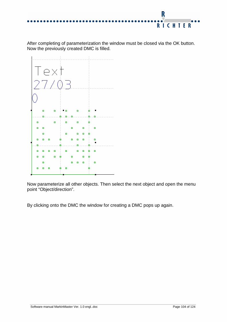
After completing of parameterization the window must be closed via the OK button. Now the previously created DMC is filled.
Now parameterize all other objects. Then select the next object and open the menu point “Object/direction”. By clicking onto the DMC the window for creating a DMC pops up again.

Software manual MarkinMaster Ver. 1.0 engl..doc Page 105 of 124
The content of the DMC will be output in the upper window. The sequence of the DMC data is depending on the marking sequence.
For details on how to modify the marking sequence, please see chapter „Modify mar-king sequence“.

Software manual MarkinMaster Ver. 1.0 engl..doc Page 106 of 124
15.2 DataMatrixCode Options
Drop-down menu DataMatrixCode � DataMatrix Options
Hotkey None
Illustr. 8: Options DataMatrixCode The following options are available:
• Mark squares instead of dots
• Interrupted finder pattern
o Mostly used for dot peen codes
• Rectangular DMC
o Often used for round workpieces
• Vertical DMC
o Here you turn the displayed code 90° counter clock wise
• Mark bi-directional
o The marking will be marked in left as well as in right-hand direction, so the operating speed will be enormously increased
Software manual MarkinMaster Ver. 1.0 engl..doc Page 107 of 124
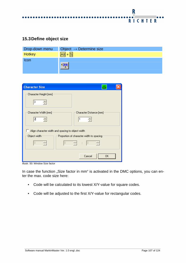
15.3 Define object size
Drop-down menu Object → Determine size Hotkey Alt + S
Icon
Illustr. 50: Window Size factor
In case the function „Size factor in mm“ is activated in the DMC options, you can en-ter the max. code size here:
• Code will be calculated to its lowest X/Y-value for square codes. • Code will be adjusted to the first X/Y-value for rectangular codes.

Software manual MarkinMaster Ver. 1.0 engl..doc Page 108 of 124
16 Help and hints
16.1 Notes on improving the marking quality
16.1.1 General
Reduce the marking speed, so a deeper marking result will be achieved. The quality of marking deteriorates with ascending marking speed. Use another type of font. The distance between workpiece and marking pin can be changed. By chang-ing the distance also the marking result will change (2-5 mm).
Using another type of marking pin can modify the quality of the marking result (see operating manual of MarkingMaster machine for details).
16.1.2 Pneumatic marking head
There are various types of marking pins available depending on the material to be marked (for details see operating manual of MarkingMaster machine).
Even changing the pressure settings can have effects on the marking result (2-5 bar).
Modify the distance of marking pin to workpiece (2-5 mm) A slow marking process results in a deeper marking compared to a fast mark-
ing process.
16.1.3 Electric marking head
There are various types of marking pins available depending on the material to be marked (for details see operating manual of MarkingMaster machine).
Modify the distance of marking pin to workpiece (2-5 mm) A slow marking process results in a deeper marking compared to a fast mark-
ing process. The marking result can be changed by setting frequency and depth.

Software manual MarkinMaster Ver. 1.0 engl..doc Page 109 of 124
16.2 Hints on how to increase the marking speed In order to increase the marking speed it is possible to adjust the sequence of mark-ing. Combined with the option “Mark backwards” the best possible marking result is achieved (only MarkingMaster Professional).
The marking speed is also depending on the font used. The more complex the font is, the longer the marking time is.
In MarkingMaster Professional software there can be another type of font used for every object. Mark the respective object. Then push the button “Font” and select the desired font.
Object Object
Object Object
forward
backwards
Sequence 1 2
3 4

Software manual MarkinMaster Ver. 1.0 engl..doc Page 110 of 124
16.3 Graphic backdrop
Configurating a graphic backdrop has got the advantage that the positioning of ob-jects is facilitated. A graphic configurated as graphic backdrop will not be marked.
In order to configurate a graphic as graphic backdrop, first a graphic must be im-ported.
After import of graphic its size has to be scaled at first. Then the graphic needs to be positioned. Choose the submenu point “Use selected graphic as graphic backdrop“ in the menu “Graphic” in order to be able to position the graphic. Ensure that the graphic has been selected (highlighted in green colour).
As soon as this function has been executed, the graphic cannot be changed any-more. The graphic is highlighted in grey now.

Software manual MarkinMaster Ver. 1.0 engl..doc Page 111 of 124
The corresponding data can be moved into the graphic. This facilitates the position-ing of objects so much.
Particulary for the marking of tags this is very advantageous.
If you require a graphic backdrop for your application, it can be created in a way meeting your requirements.

Software manual MarkinMaster Ver. 1.0 engl..doc Page 112 of 124
17 Fonts There are different types of fonts stored in the marking software in order to meet cus-tomer-specific applications.
17.1 OCR-font OCR-font has been especially designed for reading of plain text via camera. OCR-font of the company Richter corresponds to OCR_A standard.
Illustr. 51 Example OCR-font
17.2 Din 1451 DIN 1451 is a standard lettering, which is frequently used in the industrial sector.
Illustr. 52 Example DIN 1451 font
Software manual MarkinMaster Ver. 1.0 engl..doc Page 113 of 124
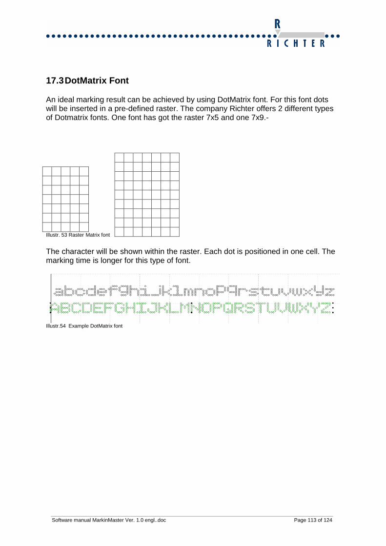
17.3 DotMatrix Font An ideal marking result can be achieved by using DotMatrix font. For this font dots will be inserted in a pre-defined raster. The company Richter offers 2 different types of Dotmatrix fonts. One font has got the raster 7x5 and one 7x9.- Illustr. 53 Raster Matrix font
The character will be shown within the raster. Each dot is positioned in one cell. The marking time is longer for this type of font.
Illustr.54 Example DotMatrix font

Software manual MarkinMaster Ver. 1.0 engl..doc Page 114 of 124
18 Error messages
18.1 Home point not reached One of the reference switches has not been reached. Possible reasons:
• Switch is defective. • Switch has got a cable.
18.2 Marking window exceeded The object is positioned outside of the max. marking window. Please correct the posi-tion.
18.3 System not ready to receive
Possible reasons:
• MarkingMaster is switched off.
• USB plug is not properly connected.
18.4 Invalid Port number
The set USB port does not match the connected one.
Troubleshooting
Please open the systems settings.

Software manual MarkinMaster Ver. 1.0 engl..doc Page 115 of 124
Now choose the submenu point „System off“.
Illustr. 55 System settings
By clicking onto the tab „Hardware“ you will access the „Device manager“.

Software manual MarkinMaster Ver. 1.0 engl..doc Page 116 of 124
Illustr. 56 Window Systems properties
USB port will be installed as a virtual Com port. There are 2 virtual Com ports for a MarkingMaster with electric marking head. One port is used for communication with the electric head and the other one for communicating with the axes.
Software manual MarkinMaster Ver. 1.0 engl..doc Page 117 of 124
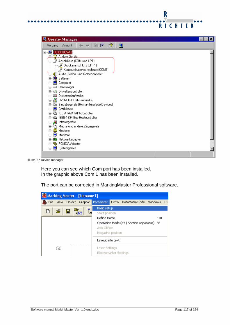
Illustr. 57 Device manager
Here you can see which Com port has been installed. In the graphic above Com 1 has been installed. The port can be corrected in MarkingMaster Professional software.

Software manual MarkinMaster Ver. 1.0 engl..doc Page 118 of 124
Illustr. 58 Screen Basic settings
18.5 No access to HPGL graphic
The graphic save in the layout has been deleted or moved. Please re-import the graphic or copy the graphic into the working directory.
Illustr. 59 Graphic Import
18.6 No access to font The font save has been deleted or moved. Define the font again or copy it into the working directory.
Icon Change font

Software manual MarkinMaster Ver. 1.0 engl..doc Page 119 of 124
19 Addendum
19.1.1 Checkbox/Radiobox
Checkbox (selection box, control box) is a standard element of a graphical user in-terface (GUI). A Checkbox has got 2 statuses for the most part, rarely 3 statuses:
• Status 1: Not marked (false) • Status 2: Marked (true) • Status 3: Not activated
Illustr. 60 Checkbox Illustr. 61 Radiobox Selection queries are often realized via a Checkbox/Radiobox. When working with a Radiobox the field is selected via a point, the Checkbox via a tick.
Illustr. 62 Example Combobox

Software manual MarkinMaster Ver. 1.0 engl..doc Page 120 of 124
19.1.2 GUI (Graphical User Interface) A graphical user interface is a software component, which enables the user to oper-ate the software via graphical icons. The graphics and elements can mostly be con-trolled via mouse or touch panel. The best-known graphical user interface is Win-dows.
Illustr. 63 Example Text-based interface
Illustr. 64 Example Graphical user interface
19.1.3 HPGL format The Hewlett Packard Graphic Language (HPGL) is a descriptive language for si-tes/pages for controlling pen plotters. Other manufacturers of plotters have adopted the HPGL language for the control of their plotters too. HPGL is a simply structured language. The commands consist of 2 capital letters, which are followed by one or more arguments. The data transfer is effected in ”plain text” (ASCII).

Software manual MarkinMaster Ver. 1.0 engl..doc Page 121 of 124
19.1.4 OCR OCR is the abbreviation for Optical Character Recognition. There are special fonts which corresponds to this standard. These special fonts are required for reading a plain text via a camera.

Software manual MarkinMaster Ver. 1.0 engl..doc Page 122 of 124
19.2 Table of abbreviations Illustr. 1 Installation assistant ................................................................................................................ 13 Illustr. 2: Created programme group .................................................................................................... 14 Illustr. 3: Select path to MarkingMaster.exe .......................................................................................... 15 Illustr. 4: Created shortcut ..................................................................................................................... 15 Illustr. 5 Teach In dialogue .................................................................................................................... 18 Ilustr. 6: Main menu bar......................................................................................................................... 21 Illustr. 7: Example: Drop-down menu “Object” ...................................................................................... 21 Illustr. 8: Tool bar left ............................................................................................................................. 21 Illustr. 9: Tool bar right........................................................................................................................... 21 Illustr. 10: File �Save as ...................................................................................................................... 24 Illustr. 11: File � Import......................................................................................................................... 25 Illustr.12: File � Export......................................................................................................................... 26 Illustr.13:Dialogue window „Marking“ .................................................................................................... 27 Illustr. 14 Windows cascade.................................................................................................................. 29 Illustr.15 Windows tile............................................................................................................................ 29 Illustr. 16: Drop-down menu previously opened files ............................................................................ 30 Illustr. 17: Drop-down menu View ......................................................................................................... 31 Illustr. 18: Show Object sequence......................................................................................................... 34 Illustr. 19: Drop-down menu Object....................................................................................................... 35 Illustr.20: Object is a fixed text............................................................................................................... 37 Illustr. 21: Settings for variables ............................................................................................................ 38 Illustr. 22: Dialogue window „Text position“......................................................................................... 44 Illustr. 23 Modified character size and width ......................................................................................... 45 Illustr.24:Size factor ............................................................................................................................... 47 Illustr. 25: Define object size.................................................................................................................. 48 Illustr. 26 Circular marking Start/end angle ........................................................................................... 58 Illustr.27: Duplicate object ..................................................................................................................... 69 Illustr. 28: Protect object ........................................................................................................................ 70 Illustr. 29 View Marking sequence - inactive ......................................................................................... 72 Illustr. 30 View Marking sequence – active / Object in marking sequence one step forward .............. 73 Illustr.31: HPGL – Import, Select graphic file in *.plt format .................................................................. 75 Illustr. 32: Graphic converter to convert into *.plt files......................................................................... 77 Illustr. 33:Converter – Conversion process ........................................................................................... 78 Illustr. 34: Converter – Properties dialogue ........................................................................................... 78 Illustr. 35: Main menu Parameter .......................................................................................................... 80 Illustr. 36: Basic settings........................................................................................................................ 80 Illustr. 37: Define starting position ......................................................................................................... 82 Illustr. 38 Window Positioning ............................................................................................................... 83 Illustr. 39: Define operating mode ......................................................................................................... 85 Illustr. 43: Rotary device ........................................................................................................................ 86 Illustr.41: Parameter settings of electric marking head ......................................................................... 90 Illustr.42: Window Communication TCP/IP ........................................................................................... 92 Illustr. 43 Display variable content......................................................................................................... 96 Illustr. 44: Window Object layer ............................................................................................................. 97 Illustr. 45 Square DMC 10x10 ............................................................................................................... 98 Illustr. 46: Enter data for DataMatrix Code ............................................................................................ 99 Illustr. 47: Displayed DataMatrix Code ................................................................................................ 100 Illustr. 48 View objects for DMC .......................................................................................................... 101 Illustr. 49 Add object to DMC............................................................................................................... 103 Illustr. 50: Window Size factor ............................................................................................................. 107 Illustr. 51 Example OCR-font............................................................................................................... 112 Illustr. 52 Example DIN 1451 font........................................................................................................ 112 Illustr. 53 Raster Matrix font................................................................................................................. 113

Software manual MarkinMaster Ver. 1.0 engl..doc Page 123 of 124
Illustr.54 Example DotMatrix font ....................................................................................................... 113 Illustr. 55 System settings................................................................................................................... 115 Illustr. 56 Window Systems properties ................................................................................................ 116 Illustr. 57 Device manager................................................................................................................... 117 Illustr. 58 Screen Basic settings .......................................................................................................... 118 Illustr. 59 Graphic Import ..................................................................................................................... 118 Illustr. 60 Checkbox Illustr. 61 Radiobox...................................................................................... 119 Illustr. 62 Example Combobox............................................................................................................. 119 Illustr. 63 Example Text-based interface ............................................................................................. 120 Illustr. 64 Example Graphical user interface........................................................................................ 120
19.3 Overview of tables Table 1 Overview System requirements .............................................................................................. 12

20 Contact
J O A CHI M R I CHT E R e .K . S y s t e m e u n d M a s c h i n e n Erlenhöhe 3-5 – Industriegebiet D - 6 6 8 7 1 K o n k e n G e r m a n y Phone: +49 – (0) 63 84 - 92 28 0 Fax:+49 – (0) 63 84 - 92 28 77 E-Ma i l : i n fo@j r - r i ch te r .de h t t p : / / w w w . j r - r i c h t e r . d e