marine air chiller compact installation & operation … and recreational marine craft, vehicles...
TRANSCRIPT
Chilled Water SystemsRevised: 20140404L-2177 Y English
chiller compactInstallation & Operation

3 Y English L-2177
TABLE OF CONTENTS
Copyright 2006 Dometic Corporation, All Rights Reserved - Every precaution has been taken in the preparation of this manual to insure its accuracy. However, Dometic assumes no responsibili-ty for errors or omissions. Neither is any liability assumed for damages resulting from the use of this product and information contained herein.
1 - Introduction 1.01 - How It Works ....................................................................................................................................................... 41.02 - Safety Considerations ........................................................................................................................................ 41.03 - Definition Of Terms Used In This Manual ........................................................................................................... 5
2 - Installation 2.01 - Electrical Grounding And Bonding ..................................................................................................................... 72.02 - Condensing Unit Installation .............................................................................................................................. 72.03 - Air Handlers ....................................................................................................................................................... 72.04 - Mounting Digital Air Handler Controls ................................................................................................................ 82.05 - Ducting ............................................................................................................................................................... 82.06 - Supply And Return Air Grilles ............................................................................................................................ 92.07 - Sizing of Ducting and Grilles .............................................................................................................................. 92.08 - AT Air Handlers .................................................................................................................................................. 92.09 - Blow Thru Air Handlers ...................................................................................................................................... 92.10 - Slim Line Air Handlers ........................................................................................................................................ 92.11 - Condensate Drains ............................................................................................................................................102.12 - Seawater Pump .................................................................................................................................................102.13 - Seawater Plumbing ...........................................................................................................................................102.14 - Chilled Water Circulation Circuit ........................................................................................................................112.15 - Manifold, Pipe And Hose Sizes .........................................................................................................................112.16 - Circulation Circuit Pressure ...............................................................................................................................122.17 - Chilled Water Pump Package ............................................................................................................................122.18 - Suggested Piping To Air Handlers .....................................................................................................................122.19 - Insulation ...........................................................................................................................................................122.20 - Piping Installation ..............................................................................................................................................132.21 - Miscellaneous Optional Components ...............................................................................................................132.22 - Checking The Circulation Circuit For Leaks ......................................................................................................142.23 - Flushing The Circulation Circuit ........................................................................................................................142.24 - Filling And Purging The Circulation Circuit ........................................................................................................14
3 - Operation 3.01 - DDC - Digital Diagnostic Control .......................................................................................................................163.02 - DDC Specifications ...........................................................................................................................................163.03 - DDC Programmable Parameters .......................................................................................................................163.04 - Fault Display Codes ..........................................................................................................................................173.05 - Using The Bimini Jumpers For Trouble-Shooting ..............................................................................................173.06 - Sequencing The Compressors ..........................................................................................................................173.07 - Start-Up Of The System ....................................................................................................................................17
4 - Maintenance 4.01 - Routine Maintenance ........................................................................................................................................184.02 - Extended Maintenance .....................................................................................................................................184.03 - Winterization And The Use Of Anti-Freeze ....................................................................................................... 204.04 - De-Winterizing ................................................................................................................................................. 204.05 - Condenser Coil Cleaning Procedure ................................................................................................................ 204.06 - Maintenance Record ........................................................................................................................................ 20
5 - Trouble-Shooting Guidelines 21
6 - Manufacturers Limited Warranty Agreement 23
7 - Description Of Figures 25
Distributor Listing 37

4 Y English L-2177 Introduction
1 - INTRODUCTION
The chiller compact® series of staged chillers are de-signed for boats 40-75 feet (12-23 meters) in length. Indi-vidual units are available in capacities of 16,000, 20,000 & 24,000 BTU/Hr and voltages of 115/60/1, 208-230/60/1, 208-230/60/3, 200/50/1, 220-240/50/1, and 220-240/50/3. These systems can provide ideal solutions for problems of space requirements, amperage consumption and weight for both new boat and retrofit applications and are designed for marine applications incorporating the following features:
coils for maximum heat transfer
25% less than conventional units
-nections
® protection to insure refrigerant integrity during handling and installation
-tection
system protection.
This manual is intended to provide the information neces-sary to ensure proper operation and maintenance of the chiller compact modules and associated air handlers. Incorrect operating procedures can result in unsatisfactory performance and/or premature failure of these units, so before proceeding please read this manual completely.
The chiller compact modules are covered under the ex-isting Marine Air Systems warranty policy contained in this manual. In the interest of product improvement, Marine Air Systems’ specifications and design are subject to change without prior notice.
MARINE AIR SYSTEMSMarine Air Systems (MAS) is a product of Dometic Envi-ronmental Corporation (Dometic). Dometic is a recognized leader in the design and manufacture of high-performance comfort control systems, refrigeration products and battery charging products for demanding environments, including commercial and recreational marine craft, vehicles and other applications. We offer an unparalleled scope of prod-ucts, dealer networks, applications support, engineering resources and production capabilities throughout the world. Our team has many years of experience in the design, manufacture, application and support of our products. Our practical experience and design capability allows our appli-cation engineers and sales representatives to offer optimum solutions for your environmental control requirements.
1.01 - How It WorksYour chilled water air conditioning system consists of the chiller condensing unit, air handlers installed throughout the vessel, fresh water piping connecting the chiller to the air handlers, the chilled water pump package, and the sea-water system. The chiller condensing unit consists of three major components: the compressor, the condenser coil, and evaporator coil. The chiller is charged with a refrigerant that circulates throughout these components. The air han-dlers consist of two major components: the blower and the evaporator coil. The pump package circulates fresh water through the piping from the chiller to each air handler and back in a continuous loop (the circulation circuit).
In cooling mode, warm cabin air is drawn (or blown) across the air handler coil by the blower. Removing heat from the cabin air cools it. The cooled air is blown back into the cabin. The heat that was removed from the cabin air is transferred to the fresh water circulating through the coil. The warmed water is pumped back to the chiller. The water is then circulated through the chiller evaporator coil where the heat is transferred to the refrigerant, thus cooling the water. The “hot” refrigerant gas is then circulated through the outer tube in the chiller condenser coil. Seawater is circulating through the inner tube of the condenser coil via the seawater system. The heat is transferred from the refrigerant to the seawater and pumped overboard taking the original cabin air heat with it. The chilled water (not seawater) is then pumped back through the piping to the air handlers in a continuous loop as the cycle repeats.
opposite direction through a reversing valve, thus adding heat to the fresh water circulation circuit, instead of remov-ing it as in the cooling mode. Some systems also use “chill chasers” which are electric heating coils built into the air handlers that warm the air directly.
1.02 - Safety ConsiderationsInstallation and servicing of this system can be hazardous due to system pressure and electrical components. Only trained and certified service personnel should install, repair, or service equipment. When working on this equipment, al-ways observe precautions described in the literature, tags, and labels attached to the unit. Follow all safety codes. Wear safety glasses and work gloves and place a fire extinguisher close to the work area.
Never install air handlers in the bilge or engine room areas. Insure that the selected location is sealed from direct ac-cess to bilge and/or engine room vapors. Do not terminate condensate drain line within three (3) feet of any outlet of engine or generator exhaust systems, nor in a compart-ment housing an engine or generator, nor in a bilge, unless the drain is connected properly to a sealed condensate
5 English L-2177 Introduction
or shower sump pump. (Fumes and vapors can travel up the condensate line.) Failure to comply may allow bilge or engine room vapors to mix with the air conditioners return air and contaminate living areas.
Danger! Electrical shock hazard. Disconnect voltage at main panel or power source before opening any electrical box cover. Failure to comply may result in injury or death.
Warning! To minimize the hazard of electrical shock and personal injury, this component must be effectively ground-ed. Refer to installation guidelines for further information.
Notice: This component is charged with either a HYDRO-CHLOROFLUOROCARBON (HCFC) refrigerant R22 or with R407c which is a “Green Gas” HYDROFLUOROCAR-BON (HFC) refrigerant. Effective July 1, 1992 it shall be unlawful for any person to know-ingly vent or otherwise knowingly release any class I (CFC) or class II (HCFC) substance as a refrigerant in a manner that permits such substance to enter the atmo-sphere per the clean air act of 1990. Public law 101-549 title IV section 608-C. Failure to comply may result in severe penalties, including fines and imprisonment.
1.03 - Definition Of Terms Used In This ManualAIR HANDLER: The evaporator/blower fan coil unit that circulates air into a specific area for heating or cooling.
AT Air Handler - The new AT air handler modelsre-places Draw Thru and Flex Duct air handlers. These are draw-through, ductable units with rotatable blowers
installation.
Blow Thru - An air handler with the fan positioned to push or blow cabin air across the air handler coil di-rectly into the cabin. No ductwork is used on this type of air handler.
Slim Line - A modular blow thru air handler available in horizontal or vertical configurations. Ductwork may be used on this type of air handler, however it must be a short plenum that is no smaller in area than the air handler’s supply air opening. The supply air grille must be no smaller in area than the air handler’s sup-ply air opening.
Aquastat: A sensor that communicates the return water temperature to the circuit board control. The control com-pares this water temperature to the desired water tem-perature (“water setpoint”) to determine whether or not the chiller should operate.
Bimini Jumper: A very small, removable connector on the circuit board. It connects two posts on the circuit board,
-ing the Bimini jumper disconnects the posts.
Bleeder Valvestubing located on the air handlers for purging air from the chilled water circulation system.
Bonding: Any metal that is isolated within the seawater circuit, or any metal that might come into contact with sea-water, should be connected to the vessel’s bonding circuit to help alleviate the effects of electrolysis (follow ABYC or applicable standards).
BTU: (British Thermal Unit) The amount of energy required to change the temperature of one pound (1 lb/0.5 kg) of water by one degree Fahrenheit (1°F/0.6°C). In air condi-tioning, the rate of heat removal is described in BTUs per hour (BTU/Hr). See the definition of “Ton” for an example.
CFM: Abbreviation for “cubic feet per minute”, a term used
and ducting. (1 CFM = 1.7 CMH)
Chill Chaser: An optional auxiliary electric heater located in the air handler.
Circulation Circuit: Supply and return piping from the chiller to the air handlers. The supply piping carries chilled water (in cool mode) from the chiller to the air handlers. Return piping carries warmed water (in cool mode) from the air handlers back to the chiller. The supply and return piping form a continuous closed loop.
Circulation Pump: The pump used to circulate fresh water between the chiller and the air handlers. Since this pump is located in a “closed loop” system, it does not need to be installed below the water line of the vessel. Whereas the seawater pump does need to be installed below the water line.
Circuit Breaker: An electrical device that provides high current and short circuit protection for the compressors and pumps. HACR (heating, air conditioning and refrigeration) type circuit breakers are recommended for the ship’s panel. HACR circuit breakers have a long delay to compensate for the electrical surge associated with compressors.
Compressor: An electrical motor/pump that compresses cool, low-pressure refrigerant gas into hot, high-pressure gas.
Compressor Overload: An electrical device used to protect the compressor from excessive heat or electrical current draw.
Condensate Drain Pan: The pan directly under the air handler’s evaporator coil that collects the condensed mois-ture that has been removed from the cabin air. There is also a condensate drain pan located under each chiller and the chilled water pump package.
Condenser Coil: The heat exchanger through which heat is transferred between the refrigerant in the chiller and the

6 Y English L-2177 Introduction
Electric Heat: Electric resistance heaters are used as a chill chaser in the air handlers to warm the air.
Expansion Tank: A container, installed on the pump pack-age, used to cushion against any water hammer in the circulation system piping. It also provides for expansion of the water volume as the water expands in heat mode.
Fan Speed Control: An “on/off” switch that also regulates the amount of voltage supplied to the fan motor, thus con-trolling the speed at which the motor turns.
Freeze Stat: A low temperature thermostat used as a control device to sense circulation water temperatures and shut the entire condensing unit off when supply water temperatures in the circulation piping system reach 38°F (3.3°C). This prevents the possibility of rupturing the chilled water evaporator coil, as well as any other piping in the system, which may happen if the water freezes.
Fresh Water Fill System: Components installed on the pump package return line for filling the circulation circuit piping system.
GPM: Abbreviation for “gallons per minute”, a term used to
High Limit Switch: A high temperature thermostat used as a safety device to shut down the condensing unit when the water temperature in the circulation piping circuit reaches 120°F/48.9°C. This prevents the possibility of damaging any PVC piping or any other components due to the water getting too hot.
High Pressure Switch: Electrical control device operat-ed by high side system refrigerant pressure. If refrigerant pressure in the system exceeds 425psig (2930kPa), then the switch will automatically open the electrical circuit and shut down the compressor. This switch resets itself automatically.
Low Pressure Switch: Electrical control device operat-ed by low side system refrigerant pressure. If refrigerant pressure in the system drops below 27psig (186kPa), then the switch will automatically open the electrical circuit and shut down the compressor. This switch resets itself automatically.
Motorized Water Valve: An optional, electrically operated, 3-way water regulating valve installed on an air handler and controlled by the thermostat. This valve provides water
return side when closed.
Pump Relay Panel (PRP): Used with more than one chiller, the PRP is a circuit board module wired between the chillers and the chilled water and/or seawater pump (one PRP for each pump). When any one of the chillers is switched on, the PRPs are energized and switch each pump on (see Digital Diagnostic Controller (DDC) instruc-
tion #4). Each PRP should have its own circuit breaker sized for the pump, but not to exceed 20 amps.
Reversing Valve: An electromagnetically controlled valve
and evaporator of the chiller condensing unit, thereby per-mitting heat to be extracted from the cabin in the cooling mode and added into the cabin in the heating mode.
Run Capacitor: An electrical storage device used to re-duce amperage to some electric motors for more efficient operation.
Seawater Pump: A pump and motor combination that pro-
The seawater pump must be installed below the water line for proper operation.
Seawater Strainer: A housing containing a screen made of metal or nylon to filter out debris drawn into the seawater circuit that could foul up the seawater pump or piping. The strainer must be located between the thru-hull inlet and seawater pump.
Stat: see Thermostat
Thermostat: An adjustable control device that senses room temperature via an air thermistor or sensor and operates
Thru-Hull Fitting: There are two different thru-hull fittings used in the seawater circuit. The speed scoop strainer inlet fitting is mounted below the water and serves as the inlet for the seawater circuit. The discharge thru-hull fitting is mounted above the water line and serves as the outlet for the seawater circuit.
Ton: In air conditioning, the amount of heat absorbed in melting one ton (2000 lbs/907 kg) of ice in a 24-hour peri-od is equal to 288,000 BTU’s. Divide 288,000 BTU’s by 24 hours to get 12,000 BTU’s per hour. Therefore, one ton of air conditioning = 12,000 BTU/Hr. (See also “BTU”.)

7 English L-2177 Installation
2 - INSTALLATION
2.01 - Electrical Grounding And Bonding
NOTE: Field wiring must comply with ABYC or applica-ble electrical codes. Power to the unit must be within the operating voltage range indicated in the data plate on the unit. Properly sized fuses or HACR circuit breakers must be installed for branch circuit protec-tion. See data plate for “MAX FUSE” (maximum fuse size (mfs) or maximum circuit breaker size) and “MIN CIR” (minimum circuit ampacity (mca)).
Chiller compact condensing units have a terminal block on the DDC circuit board mounted inside the electrical box. Connect the electrical supply wires and the pump (or PRP) wires to this terminal block. All units must be effectively grounded to minimize the hazard of electric shock and personal injury. The following rules are to be observed:
1. AC (alternating current) grounding (green wire) must be provided with the AC power conductors and connected to the ground terminal (marked “GRND”) in the electri-cal box of each chiller unit, per ABYC standard E-8, or equivalent.
2. Connections between the vessel’s AC system ground-ing conductor (green wire) and the vessel’s DC (Direct Current) negative or bonding system should be made as part of the vessel’s wiring, per ABYC standard E-9, or equivalent.
3. When servicing or replacing existing equipment that contains a chassis-mounted ground stud, the service person or installer must check the vessel’s wiring for the existence of the connection required in item 2 above.
ABYC standards are available from:
American Boat and Yacht Council 3069 Solomon’s Island Rd. Edgewater, MD USA 21036 Telephone: (410) 956-1050
The chiller must be connected to the ship’s bonding system to prevent corrosion due to stray electrical current or voltage. All pumps, metallic valves and fittings in the seawater circuit that are isolated from the unit by PVC or rubber hoses must be individually bonded to the vessels bonding system also. This will help eliminate any possibility of corrosion due to stray current or voltage.
FAILURE TO PROPERLY GROUND AND BOND THE SYSTEM WILL VOID WARRANTY!
See Figures 2.01a, 2.01b and 2.01c, for wiring diagrams.
2.02 - Condensing Unit InstallationThe chiller compact condensing units should be installed below deck, either in the engine room, machinery compart-ment, lazarette, or a similar area. They are unaffected by vibration, moisture or ambient temperatures up to 140°F (60°C). These units must be well secured on a sturdy, level surface with the mounting brackets provided. The chiller compact must be installed so that it is accessible for service. The condensing unit is hermetically sealed and requires no ventilation for proper operation. Normal engine room temperatures will not affect operation of the condens-ing unit.
2.03 - Air HandlersAir handlers are designed in three types of configurations - AT series draw-through, Blow Thru, and Slim Line - to allow
securely and level for proper operation and condensation removal. All air handlers must have an unrestricted return air stream.
VERY IMPORTANT:
Never install air handlers that are meant to condition living spaces in the bilge or engine room areas. Ensure that the selected location is sealed from direct access to bilge and/or engine room vapors. Do not terminate condensate drain line within three (3) feet of any outlet of engine or generator exhaust systems, nor in a compartment housing an engine or generator, nor in a bilge, unless the drain is connected properly to a sealed condensate or shower sump pump. (Fumes and vapors can travel up the con-densate line.) Failure to comply may allow bilge or engine room vapors to mix with the air conditioners return air and contaminate living areas.
Consideration should be given to installing a trap in the condensate drain line(s) so that normal discharge of con-densate can fill the trap and prevent the ingress of carbon monoxide (CO) or other potentially harmful vapors.
For installations on sailboats that heel over 15°, position Blow Thru and Slim Line air handlers so that the conden-sate pan drains to port and to starboard, using both drains teed together. See Section 2.11.
2.04 - Mounting Digital Air Handler ControlsBefore mounting the digital display panel touch pad consid-er the location. The air sensor built into the display panel will provide excellent cabin air temperature sensing if it is installed properly. The display panel should be mounted on

8 Y English L-2177 Installation
an inside wall, slightly higher than mid-height of the cabin, in a location with freely circulating air, where it can best sense average temperature. Do not mount the display in the supply air stream. Do not mount the display in direct sunlight, near any heat producing appliances, or in a bulk-head where temperatures radiating from behind the panel may affect performance. Do not mount the display above or below a supply or return air grille. Do not mount the display behind a door, in a corner, under a stairwell, in a locker, or any place where there is no freely circulating air.
If the display must be mounted in a location that will not allow it to properly sense cabin temperature, then an op-tional remote air sensor must be used. Mount the remote air sensor in the return air stream behind the return air grille and plug its cable (6-pin connector) into the air han-dler control circuit board. Installing the remote air sensor will override the display panel sensor.
Mount the display within cable length of the air handler (custom cable lengths are available). Plug the display cable (8-pin connector) into the back of the display panel. Secure the display panel to the bulkhead (see the air han-dler control manual for specific instructions). An optional outside air temperature (O.A.T.) sensor and 6-pin cable may also be used. Mount this sensor outside, but not in direct sunlight. Secure all cables; however do not staple cables when mounting.
2.05 - Ducting
system. It is highly dependent on the quality of the ducting installation. The ducting should be run as straight, smooth and taut as possible minimizing the number of 90 degree
Figure 2.07 shows minimum duct diameters and their corresponding return and supply air grille areas in square inches. If a transition box is used, the total area of supply air ducts going out of the box should equal the area of the supply duct feeding the box. To calculate the square inch area of a round duct: divide the diameter by two to get the radius (r), multiply the radius by itself (r2), and multiply that number by 3.1416 (/). The following is a summary of proper ducting connections:
1. Pull back the fiberglass insulation exposing the inner duct hose.
2. Slide the duct hose around the mount ring until it bot-toms out.
3. Screw 3 or 4 stainless steel sheet metal screws through the duct hose into the mount ring. Make sure to catch the wire in the duct hose with the heads of the screws. Do not use band clamps, the mount rings are tapered and the hose will slide off.
4. Wrap duct tape around the ducting and ring joint to prevent any air leaks.
5. Pull the insulation over the duct to cover the mount ring; secure the insulation with duct tape.
All ducting should:
operation.
side, mechanical compartments, etc.).
The design of a proper supply ducting system in a boat begins with the outlet of the blower. The blower mount ring sizes used by Dometic are designed to keep the air velocity and frictional pressure drop relatively low. Reducing the blower ring size will create higher air velocities. Higher
and the heating or cooling capacity of the unit. A ducting system should have the same cross sectional area as the blower ring in order to keep the air at proper velocity. The following table shows the cross sectional duct area needed for all air handlers and the size of the duct ring mounted on the blower.
Several circumstances may be encountered where a larger
a particular unit. These include excessively long duct runs (greater than twenty feet), large numbers of bends in the duct runs (greater than three 90° bends), or a transition box located at the outlet of the blower. A duct size one inch larger than that shown in Figure 2.07 should be used in each of these cases.
Ducting should not be used for the return air inlet of an air handler. However, if the return air must be ducted, the return air duct size should be at least twice the size of the supply air duct.
Minimum duct length for a draw-through type air handler is five feet (5’/1.52m). If the duct is any shorter, then the blower motor noise will be heard coming out of the supply grille. The maximum duct length of twenty feet (20’/6.04m) should not be exceeded. If the duct is any longer than the
be reduced and air handler performance will be diminished.
When using ducting transition boxes, the total outlet area should be at least equal to the inlet area.
Built-in air plenums should be constructed to deliver proper
pressurized by the air delivery through the ductwork and

9 English L-2177 Installation
incorporate diffusers when necessary to create an even
The cross-sectional area of the plenum should be equal to, or slightly greater than, the area of the supply duct. Under-sized plenums create air turbulence and generally cause
prevent air leakage. Plenums constructed of wood, cloth or any other conductive material must be sealed and insu-lated properly to prevent condensation and possible water damage.
2.06 - Supply And Return Air GrillesThe return air grille should be placed as close as possible
the coil. It should also be mounted as low as possible. The return air grille should not be located in such a way that the supply air blows directly into it. This will cause “short cycling” which results in poor performance and inadequate air conditioning.
A return air filter must be used. The filter may be on the air handler unit or installed in the return air grille. Only one filter is necessary. The filter should be installed in the loca-tion that is easiest to access.
The supply air grille should be mounted as high as possi-
cool supply air falling, and forcing the warm air through the return air stream or up to the ceiling to mix with the cooler air being distributed. Failure to deliver the supply air high
-er temperatures near the ceiling.
2.07 - Sizing of Ducting and GrillesRefer to Figures 2.07 at the back of this manual.
2.08 - AT Air HandlersAT air handlers are to be installed with ducting connected to the blower outlet. See Sections 2.05, 2.06 and 2.07.
The blowers should be rotated so the outlet is in line with the ducting. Transition boxes may be used to divide the duct system into multiple locations. Install these air han-dlers low in the cabin area, under seats or berths, or in the bottom of lockers, to maintain a return air stream close to
ceiling in such a way that the air is blown across the room. The supply air must not blow directly toward the return air grille. Fasten the air handlers with the mounting brackets and screws provided. See Figure 2.08.
2.09 - Blow Thru Air HandlersBlow Thru (BT) air handlers do not use ducting; the supply air is blown directly through the evaporator coil and into the cabin. Install these air handlers high in a cabin area, at the top of lockers, bulkhead corners or overhead compartments. Since no ducting is used, blow thru air handlers must be installed in such a way as to deliver air directly into the cabin area being conditioned.
to the bulkhead or partition, behind the supply air grille. They should be fastened securely using the four mounting grommets located in the upper four corners of the mount-ing plate.
The supply air grille must be at least equal in surface area and dimensions to the evaporator coil surface. Return air must come from the same area that is being conditioned. The return air grille should be the same size as the supply air grille, no less than the surface area of the coil and be located underneath, alongside, or behind the BT air han-dler. See Sections 2.06 and 2.07.
bulkhead or partition, a plenum chamber can be attached between the face of the coil and the inside of the partition. This plenum must be equal or slightly larger than the coil surface, sealed completely, and be a short, straight run. Due to their design, the blow thru air handlers cannot be connected to excessively long plenums, multi-directional plenums, or any ducting. See Figure 2.09.
2.10 - Slim Line Air HandlersSlim Line (SL) air handlers are used in situations where space is limited. They are similar in application to the blow thru air handlers. However, slim line air handlers can also be mounted low in side panels and narrow bulkhead spaces. The slim line is constructed in either a horizontal or a vertical configuration. The horizontal configuration is used for overhead mounting and the vertical configuration is used for low mounting behind bulkheads and panels. The supply and return air grilles must be at least the same size as the outlet and inlet of the unit, respectively (See Section 2.07). Slim line units can be ducted with the use of plenums. Follow the same guidelines for the blow thru units or plenum construction (See Section 2.09). See Figure 2.10.
2.11 - Condensate DrainsAll units come with condensate drains. When humidity lev-els are high, condensate water can be produced at a rate of up to one gallon (3.8 liters) per hour. With this in mind, it is important to route condensate drains properly. After the condensate installation is complete, test the installation by pouring a quart (liter) of water into the pan and verify proper drainage.
10 Y English L-2177 Installation
Follow these rules for installation of the condensate drain:
Attach a 5/8” (15.9mm) inside diameter (I.D.) rein-forced hose to the hose barb drain connection with a hose clamp and tighten.
Install the condensate drain downhill from the unit and aft to a proper drainage area.
IMPORTANT NOTE: Do not terminate condensate drain line within three feet (one meter) of any outlet of engine or generator exhaust systems, nor in a compartment housing an engine or generator, nor in a bilge, unless the drain is connected properly to a sealed condensate or shower sump pump. (Fumes and vapors can travel up the condensate line.) Failure to comply may allow bilge or engine room vapors to mix with the air conditioners return air and contami-nate living areas and may result in injury or death.
the condensate drain line(s) so that normal discharge of condensate can fill trap and prevent the ingress of carbon monoxide (CO) or any other potentially dan-gerous gases.
The drain lines should be installed as short and direct as possible with a continuous downhill pitch, free of loops, kinks, or upward bends.
For installations on sailboats that heel over 15°, posi-tion Blow Thru and Slim Line air handlers so that the condensate pan drains to port and to starboard, using both drains teed together (see next).
If dual drain fittings are used they may be connected with a tee (T) fitting to a single condensation drain line if a minimum 2” (5.1cm) drop exists from the base pan drains to the tee fitting.
2.12 - Seawater PumpThe chiller condensing units are water-cooled and require a properly sized seawater pump for operation. The sea-water pump is sized according to the BTU capacity of the chilled water unit. The seawater pump must be installed so that it is always at least one foot below the water line regardless of which tack the vessel is on.
have a dedicated circuit breaker sized for the pump but not to exceed 20 amps maximum.
(HP) must be connected through a pump relay panel and not the DDC control circuit board. This is true even for single stage units because the DDC control relay is not designed to handle the amp load of a larger pump.
2.13 - Seawater PlumbingSeawater flow rate should not exceed 3gpm per ton of chiller capacity. Higher flow rates may damage the condenser coil.
Seawater temperature will directly affect the chiller’s effi-ciency. This chiller can effectively cool your boat in water temperatures up to 90°F (32.2°C) and heat (if reverse cycle option is installed) in water as low as 40°F (4.4°C). Use electric heat (if installed) if seawater temperature is below 40°F (4.4°C).
Install the seawater speed scoop intake as far below the water line and as close to the keel as possible in any application, but especially on a sailboat, to keep the intake in the water when the boat heels over so that air does not get into the system. A speed scoop should
is underway. The speed scoop must be installed facing
bronze sea cock (ball valve) must be connected directly to the speed scoop intake. The sea cock must be installed an accessible location so it can be closed to stop water from
strainer, and hoses should be sized properly for the capac-ity of the chiller. Seal the speed scoop and thru-hull with a marine type sealant.
Since the seawater pump is centrifugal and not self-prim-ing, it must be mounted so that it is always at least one foot below the water line regardless of which tack the vessel is on. The pump outlet may be positioned horizon-tally or vertically, however the discharge must always be above the inlet. The pump head should be rotated toward
connections be secured by means of double/reversed stain-less steel hose clamps (two clamps installed side-by-side and facing in opposite directions). A seawater strainer be-tween the sea cock and pump is mandatory to protect the pump from debris, such as seaweed. Not using a seawater strainer will void the pump warranty and jeopardize the entire system. The seawater system must be installed with an upward incline from the sea cock through the strainer to the inlet of the pump and then up to the chiller condenser coil/manifold inlet.
Route the plumbing from the discharge outlet of the pump to the inlet connection on the condenser coil/manifold. This hose should be plumbed as straight and smooth as possible, with no loops or vertical bends, so that it is self-draining and consequently self-purging. The dis-charge outlet of the condenser must be plumbed overboard using a discharge thru-hull fitting located above the water line. The location selected for the overboard discharge thru-hull fitting should be accessible for periodic visual in-spection and as close to the water line as possible in order

11 English L-2177 Installation
to reduce noise. It is recommended that marine grade rein-forced hose be used as well as double/reversed stainless steel hose clamps throughout the seawater system. See Figure 2.13.
Follow these guidelines for installing the seawater system:
chiller should be plumbed on an uphill incline to pre-vent air traps and provide a self-purging system.
and as close to the seawater strainer and thru-hull fitting as possible.
pump and in a place where there is easy access to the strainer basket.
strainer must be equal to the inlet size of the seawater pump.
use by the chilled water system only, and be located as far below the water line and as close to the keel as possible in such a way that it is not obstructed by other thru-hull fittings or components attached to the underside of the hull.
equivalent) facing forward to maintain a constant stream of water to the seawater pump.
type sealant designed for underwater applications.
on the speed scoop thru-hull fitting. Do not separate the two fittings with hose or pipe.
position with the discharge outlet higher than the suc-tion inlet.
to provide vibration isolation between components.
installed above the water line with access for visual inspection.
straight as possible without any kinks or loops, and be securely fastened. Avoid the use of short radius elbows and fittings whenever possible. Especially try not to use 90° elbows close to the pump inlet or outlet.
-less steel hose clamps.
compound on all threaded pipe connections. If using
a compound, ensure that it is suitable and safe for the type of pipe and fittings being used.
-ter system.
2.14 - Chilled Water Circulation CircuitThe water circulation system is a “closed loop” piping circulation circuit connecting all air handlers to the chillers. Piping size is determined by the overall BTU capacity of the system. Use SCH 80 PVC, CPVC or Copper Pipe for the circulation circuit. The following chart provides information for sizing the piping. Do not installing pipe that is too small, because that will increase water velocities and cause erosion of piping. Also, if the piping is too small, excessive water pressure reductions can occur which will
performance. See Figure 2.14.
2.15 - Manifold, Pipe And Hose SizesRefer to Figure 2.15 at the back of this manual.
If individual piping runs exceed fifty feet (55’/15.24m), the next larger pipe I.D. (inside diameter) size is recommended; using a slightly larger pipe will help reduce pressure drop through the system. The “System Capacity” listed in the chart above is measured at any given point in the chilled water circulation circuit. Size the piping according to the total capacity of air handlers supplied (down stream) from that point. Ends of main (primary) and branch (secondary) pipes should be extended and capped. Extending the end of each pipe line will help to balance the water pressure, act as a cushion against “water hammer”, provide a clean-out access, guard against pipe erosion and provide proper
The chilled water circulation circuit must not be connected to the potable water system.
2.16 - Circulation Circuit PressureThe pressure gauge on the return side of the circulation circuit should be between 12-15psig (83-103kPa) when the system is running in cool mode and up to 20psig (138kPa) in heat mode.
2.17 - Chilled Water Pump PackageThe chilled water system requires a circulation pump pack-age, sized to the total air handler load, for proper operation. The pump package consists of a pump, an expansion tank, a water pressure gauge, and a fill assembly. The fill assem-
12 Y English L-2177 Installation
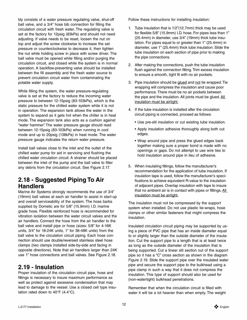
bly consists of a water pressure regulating valve, shut-off ball valve, and a 3/4” hose bib connection for filling the circulation circuit with fresh water. The regulating valve is set at the factory for 12psig (83kPa) and should not need adjusting. If valve needs to be reset, loosen the nut on top and adjust the screw clockwise to increase the set pressure or counterclockwise to decrease it, then tighten the nut while holding screw in place with screw driver. The ball valve must be opened while filling and/or purging the circulation circuit, and closed while the system is in normal
between the fill assembly and the fresh water source to prevent circulation circuit water from contaminating the potable water supply.
While filling the system, the water pressure-regulating valve is set at the factory to reduce the incoming water pressure to between 12-15psig (83-103kPa), which is the static pressure for the chilled water system while it is not in operation. The expansion tank allows the water in the system to expand as it gets hot when the chiller is in heat mode. The expansion tank also acts as a cushion against “water hammer”. The water pressure gauge should read between 12-15psig (83-103kPa) when running in cool mode and up to 20psig (138kPa) in heat mode. The water pressure gauge indicates the return water pressure.
Install ball valves close to the inlet and the outlet of the
chilled water circulation circuit. A strainer should be placed between the inlet of the pump and the ball valve to filter any debris from the circulation circuit. See Figure 2.17.
2.18 - Suggested Piping To Air HandlersMarine Air Systems strongly recommends the use of 3/4” (19mm) ball valves at each air handler to assist in start-up and overall serviceability of the system. The hose barbs supplied by Dometic are for 5/8” (15.9mm) I.D. marine grade hose. Flexible reinforced hose is recommended for vibration isolation between the water circuit valves and the air handlers. Connect the hose from the air handler to the ball valve and install pipe or hose (sizes: 5/8” for 4-16K units, 3/4” for 18-24K units, 1” for 36-48K units) from the ball valve to the circulation circuit piping. Each hose con-nection should use double/reversed stainless steel hose clamps (two clamps installed side-by-side and facing in opposite directions). Note that air handlers larger than 24K use 1” hose connections and ball valves. See Figure 2.18.
2.19 - InsulationProper insulation of the circulation circuit pipe, hose and fittings is necessary to insure maximum performance as well as protect against excessive condensation that may lead to damage to the vessel. Use a closed cell type insu-lation rated down to 40°F (4.4°C).
Follow these instructions for installing insulation:
1. Tube insulation that is 1/2”(12.7mm) thick may be used
(25.4mm) in diameter, use 3/4” (19mm) thick tube insu-lation. For pipes equal to or greater than 1” (25.4mm) in diameter, use 1” (25.4mm) thick tube insulation. Slide the tube insulation on each section of pipe prior to making the pipe connections.
2. After making the connections, push the tube insulation
to ensure a smooth, tight fit with no air pockets.
3. Pipe insulation should be glued and not tie wrapped. Tie wrapping will compress the insulation and cause poor performance. There must be no air pockets between the pipe and the insulation. All joints must be glued. All insulation must be airtight.
4. If the tube insulation is installed after the circulation circuit piping is connected, proceed as follows:
edges.
together making sure a proper bond is made with no openings or gaps. Do not attempt to use wire ties to hold insulation around pipe in lieu of adhesive.
5. When insulating fittings, follow the manufacturer’s recommendation for the application of tube insulation. If insulation tape is used, follow the manufacturer’s speci-fications to achieve equivalent R-value to the insulation of adjacent pipes. Overlap insulation with tape to insure that no ambient air is in contact with pipes or fittings. All insulation must be airtight.
The insulation must not be compressed by the support system when installed. Do not use plastic tie-wraps, hose clamps or other similar fasteners that might compress the insulation.
Insulated circulation circuit piping may be supported by us-ing a piece of PVC pipe that has an inside diameter equal to or slightly larger than the outside diameter of the insula-tion. Cut the support pipe to a length that is at least twice as long as the outside diameter of the insulation that is being supported. Cut a linear slit section out of the support pipe so it has a “C” cross section as shown in the diagram Figure 2.19. Slide the support pipe over the insulated water pipe and secure the support pipe to the bulkhead using a pipe clamp in such a way that it does not compress the insulation. This type of support should also be used for (non-watertight) bulkhead penetrations.
Remember that when the circulation circuit is filled with water it will be a lot heavier than when empty. The weight

13 English L-2177 Installation
of the water will tend to compress the insulation against whatever is underneath it. This is the main reason to use a long enough support pipe - to distribute the weight of the water-filled pipe.
2.20 - Piping InstallationThe entire circulation circuit piping must be securely fas-tened in the vessel. The following recommendations should be followed:1. Secure the insulated piping using properly sized clamps
and collars to hold the pipe in place without com-pressing the tube insulation. Compressing the tube insulation will cause condensation resulting in satura-tion of the insulation and possible water damage to the interior of the vessel.
2. Any insulated pipe passing through a bulkhead should be supported with a piece of rigid material of sufficient length to distribute the weight evenly over a large area. This will prevent excessive compression of the insula-tion.
NOTE: Circulation circuit piping will be much heavier once it is filled with water. Mounting clamps, collars, and fittings must be installed to support the piping when it is full of water, without the insulation being compressed by the extra weight.
METAL TO PVC FITTINGS: If connections are made between PVC fittings and metal fittings, always use a male pipe thread on the PVC fitting and a female pipe thread on the metal fitting. Reversing the type of fittings can cause the PVC to crack if over-tightened.
90° ELBOWS: All PVC piping should be installed with as few 90° elbow fittings as possible. Excessive bends can cause pressure drop in the system, affecting performance. Avoid the use of short radius elbows and fittings whenever possible. Especially try not to use 90° elbows close to the pump inlet or outlet.
2.21 - Miscellaneous Optional ComponentsThe following are suggested for better maintenance and operation of a chilled water system.
Sight Glass: Installed in the supply or return main pipes of the circulation circuit at an accessible location, the sight
bubbles.
Strainer: Installed in the return line before the circulation pump inlet, strainers are used to filter debris and particles (residue from installation of the piping) from the circulation circuit. The strainer basket should be made of a 20 mesh stainless steel.
Ball Valves: Installed between the chiller circulation pump/strainer and the air handler loop so that each can be isolat-ed from the other for maintenance and equipment replace-ment without having to drain the circulation circuit.
Water Pressure Gauges: Two gauges installed in the circu-lation circuit, one in the supply side and one in the return side, to monitor continuously for pressure drops in the system (the supply side gauge is optional, the return side gauge is mandatory). Note that the Chilled Water Pump Package has the return water pressure gauge installed on it. If a CWPP is not used, then the gauge should be installed on the fill line.
Automatic Air Vents: Marine Air Systems recommends the use of Spirovent® and Spirotop® auto-air bleeders, especial-ly on large systems.
The Spirovent is an inline automatic air-bleeder that will remove air from the entire CW loop. Install the Spirovent in the main return line from the air handlers. It should be located before the circulating water pump but after the CW strainer and service valve. The fill assembly can be con-nected to the ½” FPT fitting on the bottom of the Spirovent, if desired, or a plug should be installed. In applications
may be installed in a branch of the air handler loop or in a parallel circuit. The parallel circuit should be located above
up into the sidestream.
If a Spirovent is installed on a Chiller Compact system, a two-gallon bladder-type expansion tank should also be in-stalled on the return water piping (to the circulation pump). The bladder-type expansion tank is required even if a CW Pump Package is used because the Spirovent will even-tually remove the air from the open expansion tank that is included in the Pump Package.
The Spirotop is a single port auto-air bleeder. The Spiro-top can be installed at high points in the air handler loop to allow air to automatically bleed when filling the system. Isolate the Spirotop with a ball valve to allow for service.
Spirovent® and Spirotop® are registered trade names of Spirotherm, Inc.
2.22 - Checking The Circulation Circuit For LeaksIt is recommended to check the circulation circuit piping for leaks while it is being installed, especially before any fittings are hidden behind walls. Test the piping in sections, rather than waiting until construction is complete, so it is easier to isolate leaks if any are found.

14 Y English L-2177 Installation
The easiest way to test the system is by pressurizing it with air. Cap off any unfinished pipe runs, and install an air fitting at a convenient location. Pressurize the system to 50psi and make sure it holds pressure for a couple of hours. If pressure drops noticeably, then repair the leak and perform the same test again until that section of the piping holds pressure.
Warning: Do not pressurize the system with air once the circulation pump is installed. Doing so might damage the pump seal.
Fill the circulation circuit with fresh water at the fill valve on the pump package. When the circuit is full of water, con-nect the hoses from the last air handler. Add enough water to bring the pressure up 35psig (241kPa); an adjustment may need to be made to the water-regulating valve. Close the fill valve, give the system thirty minutes to stabilize and then take a reading on the pressure gauge. Leave the circuit alone for 24 hours and then take another pressure gauge reading. The second reading should be within 10% more or less than the first reading. If the second reading is less than 10% below the first reading then there is a leak in the system. Locate and repair the leak and repeat the process. Once no leaks are found, continue with the next two sections of this manual.
2.23 - Flushing The Circulation CircuitAfter the chilled water system has been completely in-
any contaminants or particles in the piping. Follow these
1. Shut off the service valves to the air handlers (if in-stalled).
each air handler.
each air handler.
4. Attach these two hoses together using a hose barb. Do this at each air handler.
attaching the air handlers by following steps 4-9. See Section 2.22.
5. Install a strainer in the pipe leading to the suction side of the circulation pump to filter any debris. The strainer can be permanently installed in the system at this point to provide continuous filtering of any loose contaminants as
bubbles, anti-freeze concentrations, etc.
6. Fill the system circulation circuit with water and run the circulation pump for fifteen minutes.
7. Turn off the circulation pump and close the service valves to the pump.
8. Remove and clean the strainer basket.
9. Repeat steps 6-8 until no debris is visible in the strainer basket.
10. Upon completion of the above steps, drain the circulation circuit and reconnect the air handlers.
2.24 - Filling And Purging The Cir-culation CircuitPre-mix a anti-freeze and fresh water solution per the an-ti-freeze manufacturer’s specifications for your application. Use enough anti-freeze to prevent freezing of pipes when vessel is not in use, but do not use more anti-freeze than recommended. Mix the solution in a large container and either use a submersible Dometic PML-500 pump (recom-mended) or use the circulation circuit pump, priming the pump first, to introduce the solution into the circuit piping. Use only non-toxic, environmentally safe anti-freeze.
Follow these instructions:
1. Connect hose from submersible pump to the water fill valve and open the valve. Or, if using the circulation pump, prime the pump first then disconnect inlet hose and place it in the solution container. Another temporary hose can be connected to the manifold where the inlet hose was disconnected, and that hose should empty into the solution container to complete the chilled water circulation circuit.
2. Turn the air handler circuit breakers ON
3. Set all of the air handler controllers to open their motor-ized water valves, if installed (refer to air handler control manual). Water valves may be opened manually if no power is available. Access the lever on top of the valve by removing the rubber cover. NOTE: if air handlers have no water valves then ignore this instruction.
4. Locate the bleeder valves on the air handlers on the highest deck.
5. Loosen the bleeder valve on each air handler to allow air and water to drain into the air handlers’ condensate pan.
6. Start the pump. If a submersible pump is used, do not run the circulation pump at the same time.
7. Periodically check the air handler condensate pans for proper drainage.
8. When no more air is coming out of the air handler bleed-er valve, and a continuous stream of water is visible, tighten the cap on the bleeder valve.
9. Repeat steps 5-8 on every remaining air handler working down from the top deck.
15 English L-2177 Installation
10. Check all fittings and connections for leaks at this time. If a leak is found, close the fresh water fill valve and repair the leak, and then repeat steps 1-9.
11. Steps 4-8 may need to be repeated until all air is re-moved from the circulation circuit.
12. Turn the air handler circuit breakers OFF.
13. Turn the pump off and reconnect original hoses. Close the fresh water fill valve.
14. The pressure gauge should read between 12-15psig (83-103kPa). Use the water-regulating valve to adjust system pressure. See Section 2.22. The CW fill pressure of 12psig is standard, but if the highest air handler is more than 25’/7.6m above the circulation pump, the pressure might need to be raised a few PSI.
For protecting the environment, collect and discard all discharged anti-freeze solution in accordance with federal, state or local regulations.

16 Y English L-2177 Operation
3 - OPERATION
3.01 - DDC - Digital Diagnostic ControlFollow these instructions to connect and set the program-mable parameters of the DDC circuit board(s). All wires connected to DDC terminal block should have captive fork or ring type terminal connections. See Figure 3.01.
1. With main circuit breaker off, connect the System Con-trol Switch wires to the circuit board as shown in Figure 3.01 (if the switch is located on the electric box then it is already wired).
2. Connect pump or Pump Relay Panel (PRP) wires. Wires connected to pumps should be tightly crimped and insulated with “heat shrink” wire wrap. Pumps larger than 3/4HP (559 watts) require a dedicated PRP. Each PRP should have its own circuit breaker sized for the pump, but not to exceed 20 amps.
3. Connect main power supply from a dedicated circuit breaker; see unit data plate for electrical specifications.
4. With the System Control Switch turned OFF, turn on the chiller’s circuit breaker.
VERY IMPORTANT: Proper setting of all the DDC Circuit Board programmable parameters must be completed and verified before starting the system! Please see section 3.03 for details on how to check and set the DDC programmable parameters. See also the DDC Operations Manual (L-2281) for more detailed information.
3.02 - DDC Specifications
after the circuit breaker is switched on.
temperatures are alternately displayed while the sys-tem is operating.
3/4HP (559 watts) must be controlled through a PRP because the relay on the DDC is not designed to han-dle the amp load of a larger pump.
chiller power switch is on in heat or cool.
plugged into the DDC socket labeled “RETURN”.
-tors freeze stat and high limit temperatures in reverse cycle chillers and is plugged into the DDC socket labeled “FREEZE”. The freeze stat opens at 38°F (3.3°C), closes at 50°F (10.0°C) and is ignored in heat mode. The high limit switch opens at 125°F (51.7°C), closes at 110°F (43.3°C) and is ignored in cool mode.
3.03 - DDC Programmable ParametersTo check the DDC programmable parameters, press the SELECT button until you see the desired program item. The current setting will be displayed after a short delay. To modify the parameter setting, press and hold the SET button until the desired setting is displayed. Releasing and pressing the SET button again will move the setting in the opposite direction.
The parameter settings that need to be checked and/or set are as follows in the order in which they will be displayed:
CSP - Cooling Set Point - If a system has more than one chiller stage, set the CSP for stage #1 to 48°F (9°C), #2 to 50°F (10°C), #3 to 52°F (11°C), #4 to 54°F (12°C), and #5 to 56°F (13°C). As the return water temperature decreases (in cool mode) the chillers will cycle off as the set point temperatures are reached and cycle on when the tempera-ture is 2°F (1.1°C) above the set point.
HSP - Heating Set Point - If a system has more than one chiller stage, set the HSP for stage #1 to 110°F (43°C), set #2 to 108°F (42°C), #3 to 106°F (41°C), #4 to 104°F (40°C), and #5 to 102°F (39°C). As the return water tem-perature increases (in heat mode) the chillers will cycle off as the set point temperatures are reached and cycle on when the temperature is 2°F (1.1°C) below the set point.
dl – Staging Delay – If a system has more than one chiller stage, set the staging delay for chiller #1 to 30 seconds, set chiller #2 to 60 seconds, #3 to 90, #4 to 120, and #5 to 150. The compressors will now come on at 30-second intervals.
°F or °C – Temperature Units – Select the appropriate temperature units.
rc or EH – Reverse Cycle or Electric Heat – If the system is equipped with the electric heat option, select EH for this parameter.
clc or con – Cycled or Continuous seawater pump opera-tion – Select the desired seawater pump operation, either cycled on demand with the compressors or on continu-ously whenever the chiller breaker power is turned on. If set to “clc” the pump will come on 10 seconds before the compressor and cycle off 10 seconds after the compressor shuts down.
LPE or LPd – Low Pressure Freon detection enabled or disabled – If the system is equipped with a low pressure switch, this parameter must be set to LPE (enabled).
AC – AC line voltage monitor – AC line voltage is dis-played. Only authorized service personnel should adjust this parameter, if necessary.
17 English L-2177 Operation
3.04 - Fault Display CodesHiP System goes off on High Pressure, lockout will occur
after four faults, reset with system switch.
LoP System goes off on Low Pressure, lockout will occur after four faults, reset with system switch.
FrE Freeze Stat fault, supply water temperature is colder than 38°F (3°C).
Sen Return Water Sensor has failed.
HiL High Limit Switch fault, supply water temperature is hotter than 125°F (52°C).
FSn Supply Water Sensor has failed.
LAC Low AC voltage (less than 85 for 115VAC, and less than 170 for 230VAC).
See Section 5 - Trouble-Shooting Guidelines, for more information.
3.05 - Using The Bimini Jumpers For Trouble-ShootingWARNING: SWITCH MAIN POWER OFF BEFORE OPEN-ING THE ELECTRICAL BOX!
The Bimini jumpers can be used to force a system output on for trouble-shooting or emergency operation. These jumpers override all fault codes. The system should not be left unattended when any of the system outputs are forced on.
The jumpers are labeled as follows:
“COMP” = compressor
“CWP” = circulation water pump
“SWP” = seawater pump
“VLV” = reversing valve
3.06 - Sequencing The Compres-sorsIn normal operation of a multi-stage system, the #1 com-pressor is always first on and last off, thereby logging more hours of run time than any of the other compressors. In order to average out the run time for all compressors over the life of the system, it is recommended to rotate the se-quence of the lead compressor every six months. This can be done by resetting the cooling and heating set points and staging delays on each unit’s DDC. Before starting, label each compressor with its new designated number; the cur-rent DDC #1 takes last place, #2 becomes #1, #3 becomes #2, etc. After labeling is complete and main power has
been disconnected, reset the “CSP”, “HSP” & “dl” program-mable parameters per specifications in Section 3.03.
IMPORTANT: If the pumps are connected directly to the lead compressor’s DDC (i.e., if there are no PRPs) then the pump wires must be moved to the new #1 DDC.
NOTICE: Resequencing the compressors is unnecessary if the systems is controlled by the optional CWMC (Chilled Water Master Control).
3.07 - Start-Up Of The SystemThe following procedure should be followed when starting the chilled water system. With the installation complete and the circulation circuit filled with water and purged of air:
1. Open the sea cock valve to the seawater system.
2. Open all manifold and air handler valves, if installed.
3. Turn on all the system circuit breakers: chiller, pumps and air handlers.
4. Open all the air handler water valves (if applicable) by adjusting their respective controllers. (Refer to air han-dler control manual.)
5. Set desired cabin temperatures at air handler controls.
6. Turn all chillers on (COOL or HEAT) at the system con-trol switches.
7. Check for a steady, solid stream of water from the over-board discharge.
NOTE: In a multiple unit system, never run one chiller in cool while running another one in heat.

18 Y English L-2177 Maintenance
Chilled water systems require basic minimal maintenance to insure proper operation and long-term reliability. Routine maintenance should be performed at frequent intervals. These intervals - daily, weekly, and monthly - will vary from vessel to vessel due to its location and usage. Extended maintenance should be performed at semi-annual or annu-al intervals; these intervals will also vary. Winterization of a system may be required for vessels stored or operating in extremely cold climates.
4.01 - Routine MaintenanceThe seawater strainers and thru-hull fittings must be in-spected and cleaned regularly to provide sufficient sea-
pressures, temperatures and amperages causing excessive wear on internal compressor components and possible nuisance tripping on the pressure switches.
for marine growth on the basket wall. This should be removed prior to reinstallation.
from the strainer housing.
The chilled water circulation circuit must be filled com-pletely with water. Air in the circuit will inhibit performance. Return water pressure should be between 12-15psig (83-103kPa) while in cool mode and when the system is off. Return water pressure may get as high as 20psig (138kPa) in heat mode due to water expansion. Discharge (supply) water pressure should be 25-30psig (172-207kPa) while the system is running. Systems without gauges must rely on the lack of cooling or heating from the air handlers, or audible noise in the pipes to determine that air exists in the circuit. Note: Continual recurrence of air in the system, or pressure loss, is a sign of a water leak in the circuit.
Return air filters for each air handler must be inspected and cleaned or replaced regularly to provide sufficient
performance of an air handler, resulting in reduced cooling or heating capacity.
Filters can be located on the air handler coil or on the back of the return air grille or opening. Access the filter through the existing cabinetry or by removing part, or all, of the grille. Remove the filter and vacuum or wash it to remove particles, lint, etc. Do not use soaps or solvents when washing. Allow filter to dry and then reinstall it securely in place.
Or use Dometic’s new Micro-Particle Anti-Allergenic air fil-ters instead of the standard type. These new filters capture smoke, dust, lint, odors, pet dander and other airborne
micro-particles that are invisible to the naked eye. They mount directly to the air handler, are disposable and should be replaced rather than cleaned. Contact your Marine Air dealer for ordering information.
Electrical connections should be inspected and tightened as needed. Heat and vibration can cause connectors to loosen causing poor contact and voltage drop or arcing. This may cause components to operate poorly or fail prematurely, and nuisance tripping of the circuit breaker. To service electrical components:
replacing components or wires.
components (contactors, timers, relays, etc.).
connections, etc. If any are found, the connector or connection should be replaced or repaired.
meter periodically to insure a proper power supply. Compressors, pumps, fans, etc. are electrically rated with a ±10% value for voltage.
It is recommended that all systems be operated regular-ly. Vessels not in use should have their chillers and air handlers switched on and run for at least one hour, once a month. Vessels in regular use should do the same for units that are not operated on a regular basis. Systems should also be occasionally switched to their reverse mode (from cool to heat and from heat to cool). Running the system at regular intervals helps to maintain pump seals and inter-nal mechanical contacts (such as reversing valves), while reducing the fouling effect of marine growth in the seawater circuit.
4.02 - Extended MaintenanceCondenser coils and seawater hoses installed below the waterline can become fouled over a period of time due to marine growth and/or scale build-up inside the coils. This
causing compressors to operate continuously with higher temperatures, amperages, and refrigerant pressures.
and cleaned by connecting a closed loop system and circulating a scale dissolving solution. See Section 4.05.
can provide this service.
The seawater pump housing and impeller shroud should
4 - MAINTENANCE

19 English L-2177 Maintenance
be checked for wear. Pump seals should be checked and lubricated according to each pump manufacturer’s recom-mendations. Worn or pitted impellers should be replaced. Any signs of corrosion should be addressed immediately. Some pumps have oil ports and may need occasional oiling. See the pump manufacturer’s label to be sure.
Seawater pump manufacturer’s maintenance recommen-dations:
from exterior of motor and pump. Keep motor air inlet and outlet open. Blow out interior of open motors with clean compressed air at low pressure. Regularly drain moisture from TEFC (Totally Enclosed Fan Cooled) motors.
-tor with Underwriters’ Laboratories label that original clearances be held: that all plugs, screws and other hardware be fastened securely, and that parts re-placed be exact duplicates or approved equals. Viola-tion of any of the above invalidates Underwriters’ label.
other than the motor bearings, according to the follow-ing instruction:
-cated bearings are furnished, then no lubrication is required for the life of the bearings. Inspect bear-ings periodically to determine the condition of the grease and replace the bearings if necessary.
shield bearings are furnished periodic inspection, cleaning and relubrication is required. See motor manufacturer’s specific instructions on the pump label.
Air handler motorized water valves (if installed) should be inspected for corrosion that may bind the gear mechanism.
water valve and remove the rubber cover and the aluminum motor case. If the rubber cover is missing, a replacement should be ordered and installed.
motor gear and/or the valve gear.
equivalent.
on the top of the valve before reassembly.
Air handler condensate drain pans should be inspected for proper drainage.
drain pan for standing water. If any significant water is
present, check the condensate drain lines for improper installation (upward loops above the pan, kinked lines, etc.). Check the drain connection to the pan for any obstructions.
water into the pan. Make sure it drains immediately and thoroughly down to the bottom of the drain con-nection. If not, check as above.
All control probes and sensors should be inspected for proper location and fastening. Improperly located and/or secured probes will provide erroneous readings, causing improper operation.
chilled water unit.
-pact should be inserted all the way into the well, filled with thermal mastic for efficient heat transfer, and insulated on the end to hold the probe in place and prohibit condensation.
be securely fastened with thermal mastic between the contact surfaces and insulated to provide accurate readings.
-tion. Water sensors should be securely fastened and insulated on the supply connection (water inlet) of the air handler. If the built in air sensor on the controller display panel is not utilized, the remote air sensors should be located in the return air stream, as close to the cabin area as possible, without being in contact with any other hot or cold surface. All sensors should be securely fastened.
Any rust or corrosion present should be inspected imme-diately. The presence of water due to condensation from the circulation circuit may cause rusting on any bare metal. Bare metal should be cleaned, primed and coated. Sources of condensation should be located and properly sealed. If corrosion is present, the source of the corrosion, either gal-vanic or chemical, should be determined and then should be dealt with in the appropriate manner.
See Section 3.06 - Sequencing the Compressors, for long term compressor maintenance.
4.03 - Winterization And The Use Of Anti-FreezeWinterization of the chilled water circulation circuit is necessary for vessels stored in extremely cold climates. A anti-freeze solution should be introduced into the circula-tion circuit to protect pipes and hoses from freezing and bursting. The percentage of anti-freeze should be selected based on the following definitions of freeze protection and

20 Y English L-2177 Maintenance
burst protection. Use only non-toxic, environmentally safe anti-freeze.
Freeze protection should be provided for vessels that must remain operational in cold weather, or where cold weath-er start-ups may be required. Choose a solution that will prevent the formation of ice crystals at 5°F (9°C) below the lowest anticipated system temperature.
Burst protection should be provided for vessels that do not operate during the winter and where cold weather start-ups will not be required. The anti-freeze solution will prevent bursting but not necessarily be high enough to
The table in Figure 4.03 provides freeze and burst pro-tection temperatures for typical ethylene and propylene anti-freeze mixtures.
See Figure 4.03 in back of this manual.
The following procedures are recommended for winterizing:
1. Shut off the fresh water fill valve to isolate the chilled water circulation circuit.
2. Select the highest air handler with easy access and purge excess water pressure from the system at the air bleeder valve. The water can be purged into a container or into the condensation pan of the air handler as long as the anti-freeze solution is captured and not dis-charged overboard.
3. Put the bleeder line into a container of pre-mixed an-ti-freeze solution.
4. Open an air bleeder valve on an air handler located at the lowest point in the system. The water may be bled into a container or directly into the condensation pan of the air handler as long as the anti-freeze solution is captured and not discharged overboard. When the anti-freeze solution has been siphoned into the water circuit, close all bleeder valves.
5. Purge the system of any air. See Section 2.24.
6. Start the circulation pump to distribute the anti-freeze solution throughout the chilled water circuit.
7. If the system is being winterized for burst protection it is necessary to have air pockets in each of the air handlers to provide room for expansion of the anti-freeze as the solution changes phase from liquid to solid. In this case, do not purge the air from the system.
Warning: For the purpose of protecting the environment, collect and discard all discharged anti-freeze solution in accordance with federal, state and/or local regulations. Use only non-toxic, environmentally safe anti-freeze.
4.04 - De-WinterizingTo prepare the vessel for use in warmer temperatures, introduce a pre-mixed solution of no more than 15% anti-freeze using the same procedure outlined above for winterizing.
4.05 - Condenser Coil Cleaning Procedure 1. With the system switched off at the circuit breaker, dis-
connect the inlet and outlet connections of the condens-er coil seawater manifolds.
2. Use chemical resistant hoses (MAS white 5/8”, for in-stance) and adapter connections to connect the inlet and outlet of the manifold to a chemical resistant, submers-ible pump (MAS PML-500).
3. Place the pump into a container filled with a 3-5% solu-tion of muriatic or hydrochloric acid and fresh water. Use as large of a container as possible to hold the solution (5-25 gallons/19-95 liters). Pre-mixed solutions can be used, or mix water proportionately with muriatic acid or hydrochloric acid. Caution: avoid spilling or splashing the solution. Follow all warnings and recommendations given by the manufacturer of any acids or pre-mixed solutions.
4. Power the pump and circulate the solution through the manifold for 15-45 minutes depending upon the size of the coils and the extent of the contamination. Visual inspection of the solution in the container should indicate when contamination removal has stopped.
-al acid from the system.
6. Restart the system and check operational parameters (pressures, amperage, etc.) to ensure thorough cleaning has taken place. Additional cleaning(s) may be neces-sary in cases of extreme contamination.
Warning: For protecting the environment, dispose of any contaminated acid solutions in accordance with federal, state and/or local regulations.
4.06 - Maintenance RecordSee Figure 4.06 Maintenance Record

21 English L-2177 Troubleshooting
5 - TROUBLE-SHOOTING GUIDELINES
Fault: System will not start. No power to chiller.
1. Circuit Breaker at ship’s panel is off.Switch on breaker(s) and monitor operation.
2. Miswiring or bad connection at terminal block in electrical box.Check wiring diagram and correct if inconsistent, or repair bad connection.
Fault: System will not start. Chiller has power.
1. Water temperature satisfied.Switch on air handlers to load chilled water circulation circuit.
Fault: System starts but trips circuit breaker.
1. Breaker is undersized.Verify breaker size against specifications on chiller data plate.
2. Electrical short.With power off, check between ground, L1, L2, and if applicable L3 for continuity. Check components for con-tinuity between same. Correct or replace components where necessary.
3. Loose or corroded electrical connections.Check and repair as necessary.
Fault: “HiP” (High Pressure Switch fault) appears on DDC display in COOL mode.
1. System cycled on high-pressure switch. This switch monitors refrigerant pressure. It opens at 425psig and resets at 200psig. Compressor shuts down for a minimum time equal to its staging delay or until fault is cleared.
-er or condenser coils as necessary.
2. Seawater pump is air lockedBleed air from seawater circuit.
3. Seawater pump circuit breaker has tripped.Reset circuit breaker and repair if necessary.
Fault: “HiP” (High Pressure Switch fault) appears on DDC display in HEAT mode.
1. Circulating pump not operating.Pump air locked.
Open fresh water fill valve and bleed system.Circuit breaker for pump switched off.
Switch on circuit breaker. Insufficient water in chilled water circulation circuit. See Section 2.24.
Fault: “LoP” (Low Pressure Switch fault) appears on DDC display.
1. System cycled on low-pressure switch. This switch monitors refrigerant pressure. It opens between 24 and 32psig, and closes between 40 and 50psig. Compressor shuts down for a mini-mum time equal to its staging delay or until fault is cleared.Fix refrigerant leaks or restrictions. Restart chiller once pressure is above 50psig.
Check that circulation water is at correct glycol-to-water ratio, ensure that vessel has been de-winterized (see Section 4.04).
Fault: “FrE” (Freeze Stat fault) appears on DDC display.
1. System cycled on freeze stat in cool mode.Insufficient water in chilled water circulation circuit. See Section 2.24.
Temperature set point is too low. See Section 3.03.
Circulating pump is not operating (see “HiP” fault above).
Fault: “Sen” (Return Water Sensor fault) appears on DDC display.
1. Return water sensor has failed.Check connections, repair or replace failed sensor.
Fault: “HiL” (High Limit Switch fault) appears on DDC display.
1. System cycled on high limit switch in heat mode.Insufficient water in chilled water circulation circuit. See Section 2.24.
Temperature set point is too high. See Section 3.03.
Fault: “FSn” (Supply Water Sensor fault) appears on DDC display.

22 Y English L-2177 Troubleshooting
1. Supply water sensor has failed.Check connections, repair or replace failed sensor.
Fault: “LAC” (Low AC Voltage fault) appears on DDC display.
1. Insufficient AC power on start-up.Monitor voltage drop during start-up and normal operation. If a significant drop occurs, check main wiring connections. Access a larger power source if necessary.
See Section 3.05 - Using the Bimini Jumpers for Trou-ble-Shooting for more information.

23L-2177
The following warranty is extended to cover products man-ufactured or supplied by Dometic Environmental Cor-poration and is subject to qualifications indicated. Marine Air Systems warrants for the periods set forth below that products manufactured or supplied by it will be free from defects in workmanship and material, provided such prod-ucts are installed, operated and maintained in accordance with Marine Air Systems’ written instruction.
ALL IMPLIED WARRANTIES INCLUDING MERCHANT-ABILITY AND FITNESS FOR A PARTICULAR PURPOSE, ARE LIMITED TO THE TERMS AND PERIODS OF WAR-RANTY SET FORTH BELOW AND, TO THE EXTENT PERMITTED BY LAW, ANY AND ALL IMPLIED WARRAN-TIES ARE EXCLUDED.
Components comprising a complete system on a new installation are warranted for a period of one (1) year from the date of installation, but not to exceed two (2) years from the date of manufacture at the Marine Air Systems factory. Dometic will pay labor and travel costs as out-lined in its Schedule of Limited Warranty Allowances for removal and re-installation of such components for a period of one (1) year from the date of installation, but not to exceed two (2) years from the date of manufacture at the Marine Air Systems factory. OEM installed equip-ment warranties begin with the commission date of a new vessel. Costs that exceed the schedule of limited warran-ty allowances, i.e., parts, labor, limited travel allowance, removal and re-installation time are the responsibility of the customer.
Dometic will repair or replace, at its option, components found to be defective due to faulty materials or workman-ship, when such components, examined by an authorized
service dealer or a factory service representative, are found to have a defect for which the company is respon-sible. Replacement components are warranted for the duration of the remaining warranty period in effect on the original component.
This limited warranty is extended in lieu of all other war-ranties, agreements or obligations, expressed or implied, concerning Marine Air Systems’ components. This limited warranty is extended only to the original purchaser and is not transferable. This limited warranty shall be governed by the laws of the State of Florida, USA, and gives the original first end user definite legal rights.
This limited warranty does not cover damages incidental and/or consequential to the failure of Dometic’s equipment including but not limited to: normal wear, accident, misuse, abuse, negligence or improper installation, lack of reason-able and necessary maintenance, alteration, civil distur-bance or act of God.
No person or dealer is authorized to extend any other warranties or to assume any other liabilities on Marine Air Systems’ behalf, unless authorized in writing by an officer of Marine Air Systems.
Note: Dometic’s warranty does not cover the effectiveness of the installation of this product. The warranty will only cover the workmanship and materials of the products manufactured or supplied by Marine Air Systems as stated above. The installation specifications outlined in this manu-al must be properly adhered to in order for the warranty to be in effect.
6 - MANUFACTURERS LIMITED WARRANTY AGREEMENT

(This page left intentionally blank)
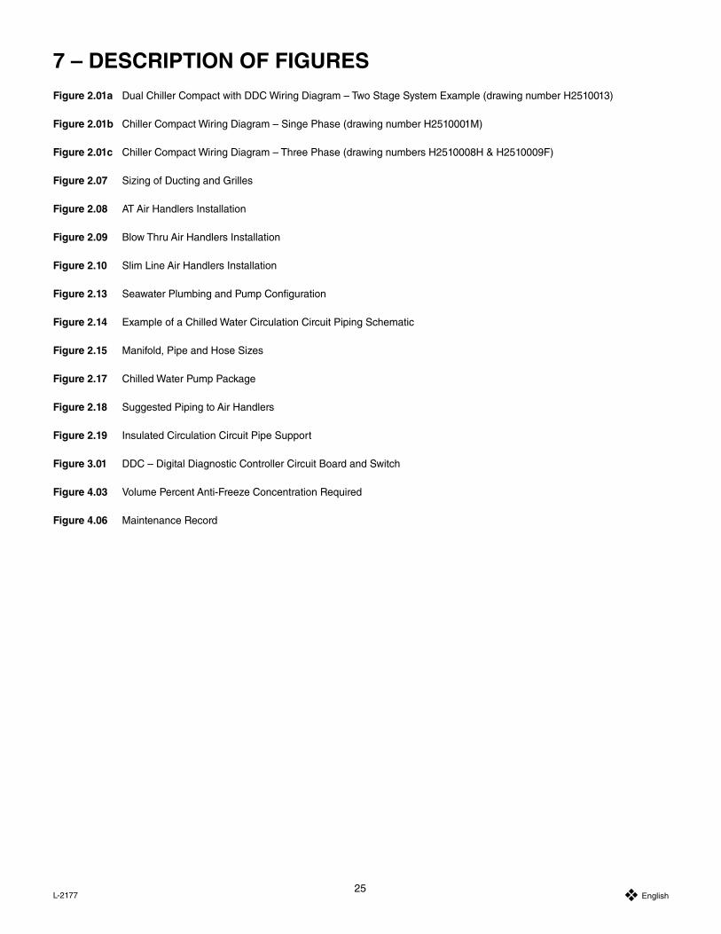
25 Y English L-2177
7 – DESCRIPTION OF FIGURESFigure 2.01a Dual Chiller Compact with DDC Wiring Diagram – Two Stage System Example (drawing number H2510013)
Figure 2.01b Chiller Compact Wiring Diagram – Singe Phase (drawing number H2510001M)
Figure 2.01c Chiller Compact Wiring Diagram – Three Phase (drawing numbers H2510008H & H2510009F)
Figure 2.07 Sizing of Ducting and Grilles
Figure 2.08 AT Air Handlers Installation
Figure 2.09 Blow Thru Air Handlers Installation
Figure 2.10 Slim Line Air Handlers Installation
Figure 2.13 Seawater Plumbing and Pump Configuration
Figure 2.14 Example of a Chilled Water Circulation Circuit Piping Schematic
Figure 2.15 Manifold, Pipe and Hose Sizes
Figure 2.17 Chilled Water Pump Package
Figure 2.18 Suggested Piping to Air Handlers
Figure 2.19 Insulated Circulation Circuit Pipe Support
Figure 3.01 DDC – Digital Diagnostic Controller Circuit Board and Switch
Figure 4.03 Volume Percent Anti-Freeze Concentration Required
Figure 4.06 Maintenance Record
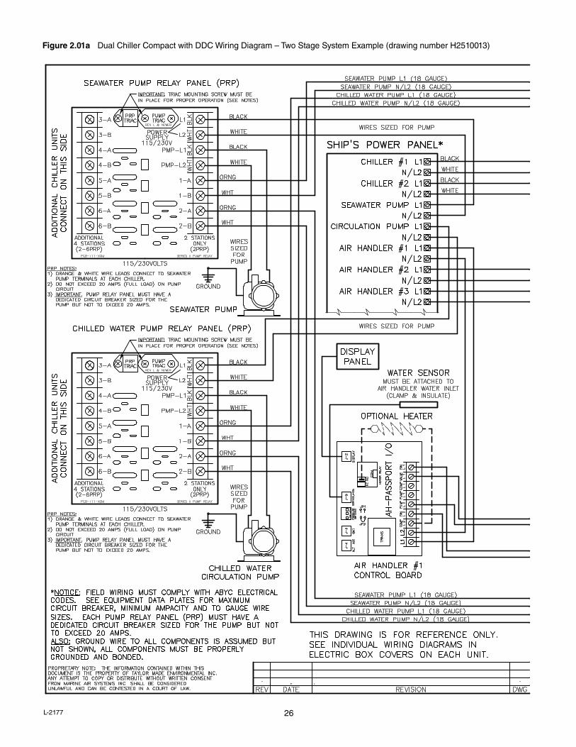
26L-2177
Figure 2.01a Dual Chiller Compact with DDC Wiring Diagram – Two Stage System Example (drawing number H2510013)
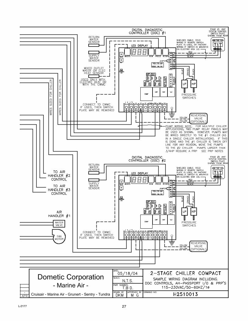
27L-2177

28L-2177
Figure 2.01b Chiller Compact Wiring Diagram – Singe Phase (drawing number H2510001M)
LED
INDICATOR
POWER
VLV
SWP
CWP
COMP
SET
DRY CONTACTHEATER RELAY
DRY CONTACT
COMP
RELAY
TRM1
TRM2
TRM1
TRM2
VLV
SWP
CWP
COMP
L2L2
L2L2
L1
EL.HEATER
COMP.
LOW
HIGHPRESSURE
TRANSDUCERS
VLV
SWP
CWP
COMP
REF
HEAT
FLOW
COOL
HIGH
FLOW
SW.
FREONSWITCH
LOW
RETURN
FREEZE
HILIM
MASTER
SELECT
FIELD WIRING, SEE NOTE
SEA PUMP
GND
GND
L2L1L1 CIRC. PUMP
L2
REVERSING VALVE
CONTROLLER (DDC)
DIGITAL DIAGNOSTIC
HP
LP
POWER
MAIN
SUPPLY
YELLOW #18
WHITE #18
NOTE:
SIZE WIRES FOR PUMP OR PUMP
RELAY PANEL (PRP). PUMPS
LARGER THAN 3/4HP REQUIRE A
PRP.
BLACK
WHITE
GREEN
GREEN
WHITE
BLACK
FOR WIRE SIZE
SEE NAME PLATE
50-60/1Ø
230 VAC
POWER
GND
L2L1
RUN CAPBLACK
PTCR
START
ASSIST
BLACK
WHITE #14
CR
S
OPT
COMPRESSOR
WHITE #14
ORANGE #14
GREEN #14
BLACK
#14
GREEN #12
WHITE #12
BLACK #12
ORANGE #18
BLACK #18
ORANGE #18
BLUE #18
BLACK
SHIELD
RED
SHIELDED C
ABLE:
ON ELECTRIC B
OX LID.
SWITCH IS MOUNTED
FACTORY W
IRING IF
PLATE IS U
SED,
REMOTE SWITCH
FIELD WIRING IF
SYSTEM CONTROL SWITCH
(SHOWN FROM REAR)
RETURN
SENSOR
WATER
CONTROL
SUPPLY
SENSOR
WATER
SAFETY
JUMPER
RE
VD
ATE
AP
RD
WG
RE
VIS
ION
DE
SC
RIP
TIO
N
PR
OP
RIE
TAR
Y N
OTE
: TH
E IN
FOR
MAT
ION
CO
NTA
INE
D W
ITH
IN T
HIS
D
OC
UM
EN
T IS
TH
E P
RO
PE
RTY
OF
DO
ME
TIC
CO
RP
OR
ATIO
N.
AN
Y AT
TEM
PT
TO C
OP
Y O
R D
ISTR
IBU
TE W
ITH
OU
T W
RIT
TEN
CO
NS
EN
T FR
OM
DO
ME
TIC
C
OR
PO
RAT
ION
SH
ALL
BE
CO
NS
IDE
RE
D U
NLA
WFU
L A
ND
CA
N B
E
CO
NTE
STE
D IN
A C
OU
RT
OF
LAW
.
Dom
etic
Cor
pora
tion
AP
R B
Y:D
WG
BY:
SC
ALE
:D
ATE
:
REV
DWG
PAR
T N
UM
BE
R:
H25
1000
1M
293-
5100
80
Mar
ine
Air
CH
C16
/20/
24K
-RC
, CO
MPA
CT
CH
ILLE
R D
DC
115-
230/
50-6
0/1Ø
12/1
1/98
NTS
RM
WJH
M10
/11/
05R
EV
ER
SIN
G V
ALV
E W
IRE
FR
OM
YE
L TO
WH
ITE
,CA
D55
2-05
DR
RM
FGG
04/2
5/00
RE
V W
IRE
CO
LOR
S A
ND
FIE
LD W
IRIN
G,C
AD
291-
00R
MW
RP
H9/
26/0
3A
DD
ED
LP
SW
ITC
H,C
AD
722-
03D
RR
JES
J5/
17/0
4R
EV
ISE
D T
O N
EW
DD
C B
OA
RD
,CA
D32
9-04
DR
RM
FGK
10/4
/05
AD
DE
D F
LOW
SW
ITC
H &
WIR
E C
OLO
RS
,CA
D54
4-05
DR
RJE
SL
10/6
/05
RE
MO
VE
FLO
W S
WIT
CH
& A
DD
JU
MP
ER
,CA
D54
9-05
DR
RJE
S

29L-2177
Figure 2.01c Chiller Compact Wiring Diagram – Three Phase (drawing numbers H2510008H & H2510009F)

30L-2177
Figure 2.07 Sizing of Ducting and Grilles
Figure 2.08 AT Air Handlers Installation
AT Air Handlers

31L-2177
Figure 2.10 Slim Line Air Handlers Installation
Figure 2.09 Blow Thru Air Handlers Installation
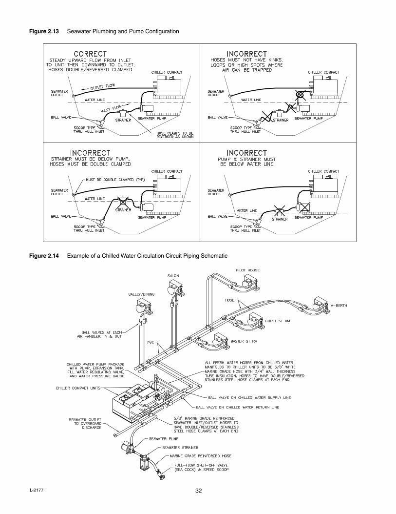
32L-2177
Figure 2.13 Seawater Plumbing and Pump Configuration
Figure 2.14 Example of a Chilled Water Circulation Circuit Piping Schematic
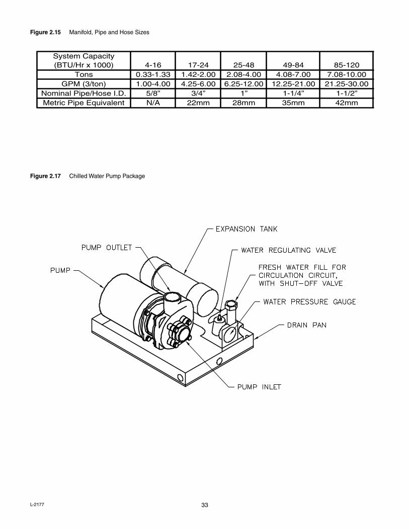
33L-2177
Figure 2.17 Chilled Water Pump Package
Figure 2.15 Manifold, Pipe and Hose Sizes

34L-2177
Figure 2.18 Suggested Piping to Air Handlers
Figure 2.19 Insulated Circulation Circuit Pipe Support
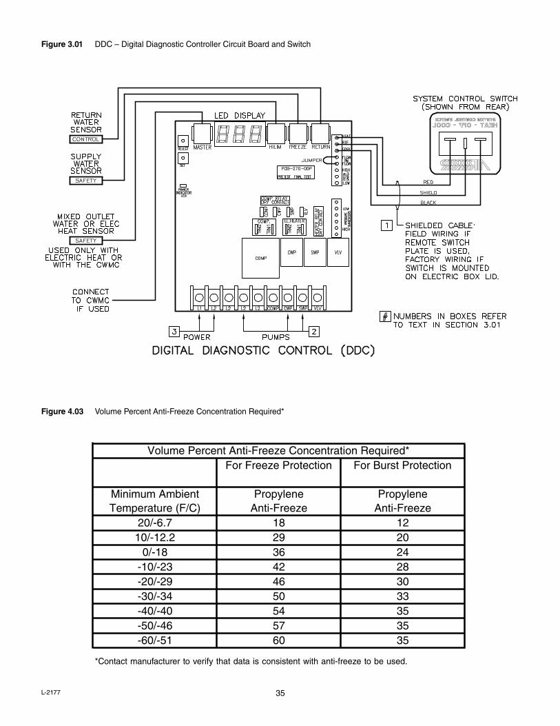
35L-2177
Figure 3.01 DDC – Digital Diagnostic Controller Circuit Board and Switch
Figure 4.03 Volume Percent Anti-Freeze Concentration Required*
*Contact manufacturer to verify that data is consistent with anti-freeze to be used.

36L-2177
Figure 4.06 Maintenance Record


L-2177
Dometic Environmental Corporation
For Sales and Service Calls within Europe and the Middle East, please contact +44 (0) 870 330 6101