maria krutikova compendium
TRANSCRIPT


Corner Raft Tower Module
Steady-State Thermal Analysis
Maria Krutikova, Kirk Arndt
Purdue
August 11, 2014
1
4
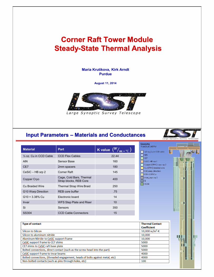
Input Parameters – Materials and Conductances
Material Part K value ( )½ oz. Cu in CCD Cable CCD Flex Cables 22.44
AlN Sensor Base 160
CE7 2mm spacers 180
CeSiC – HB srp 2 Corner Raft 145
Copper CryoCage, Cold Bars, Thermal
Strap blocks, REB Core400
Cu Braided Wire Thermal Strap Wire Braid 250
G10 Warp Direction REB core buffer .75
G10 + 3.38% Cu Electronic board 14
Invar WFS Step Plate and Riser 10
Si Sensors 350
SS304 CCD Cable Connectors 15

6
Input Parameters – CRSA Heat Loads
Average power (W)
Comment
IR load on exposed area of Corner Raft
0.48IR load on area of the front-side of the Corner Raft uncovered by
sensors (~20 cm^2).
Wavefront sensor electronics + IR load*
0.71Average WFS power (=284 mW) is 11% read and 89% quiescent duty-cycle (same duty-cycle as Science Sensor CCD).
Guide sensors electronics + IR load*
1.5 Same as two Science Sensor CDD with 100% read duty-cycle.
* IR heat load per sensor = 17.64cm^2 (area of 4kx4k sensor) x 24mW/cm^2 = 423mW per sensor(Gordon Bowden’s analysis of IR heat load on
the focal plane in the Corner Raft locations)
Note: no makeup heat applied to Corner Raft baseplate
5
Input Parameters – CREB Heat Sink and Loads
WREB GREB
• -40C contacts with cold plate
• WREB heat loads for ITL WFS
and GREB heat loads for e2v
guide sensors from Sven H.
• No radiative or conductive
losses from REBs

11
Results – CRSA
∆T of 5.5C within entire CRSA
• WFS: -109.3C Max
∆T of 1.3C
• Guider: -105.6C Max
∆T of 4.0C
LSST Camera Review • SLAC National Accelerator Lab, Menlo Park, CA • 2014 6
Overall Temperature Comparison to Science Raft
Science Raft Corner Raft
Trim Heat On0.5W x 2 heaters
Trim Heat OffTrim Heat Off
LSST Camera Review • SLAC National Accelerator Lab, Menlo Park, CA • 2014 9
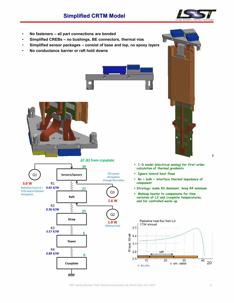
Q1 Sensors/Spacers
Raft
Strap
Tower
Cryoplate
Q2
Q3
30
27
25
5
0
ΔT (K) from cryoplate
R1
R2
R3
R4
1-D model (electrical analog) for first-order calculation of thermal gradients
Ignore lateral heat flows
Rn = bulk + interface thermal impedance of component
Strategy: make R3 dominant, keep R4 minimum
Makeup heater to compensate for time variation of L3 and cryoplate temperatures, and for controlled warm-up
0.65 K/W
0.36 K/W
3.57 K/W
0.89 K/W
3.0 W
1.0 W
1.6 W
Radiation from L3 + CCD source follower dissipation
Makeup heat
FEE power dissipation
through flex cables
Corner Raft-Tower simplified thermal model3
Simplified CRTM Model
• No fasteners – all part connections are bonded
• Simplified CREBs – no bushings, BE connectors, thermal vias
• Simplified sensor packages – consist of base and top, no epoxy layers
• No conductance barrier or raft hold downs
LSST Corner Raft PDR September 30, 2014 1
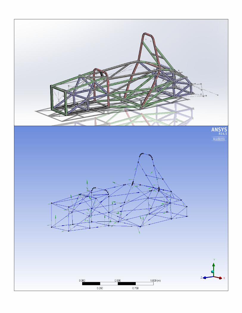
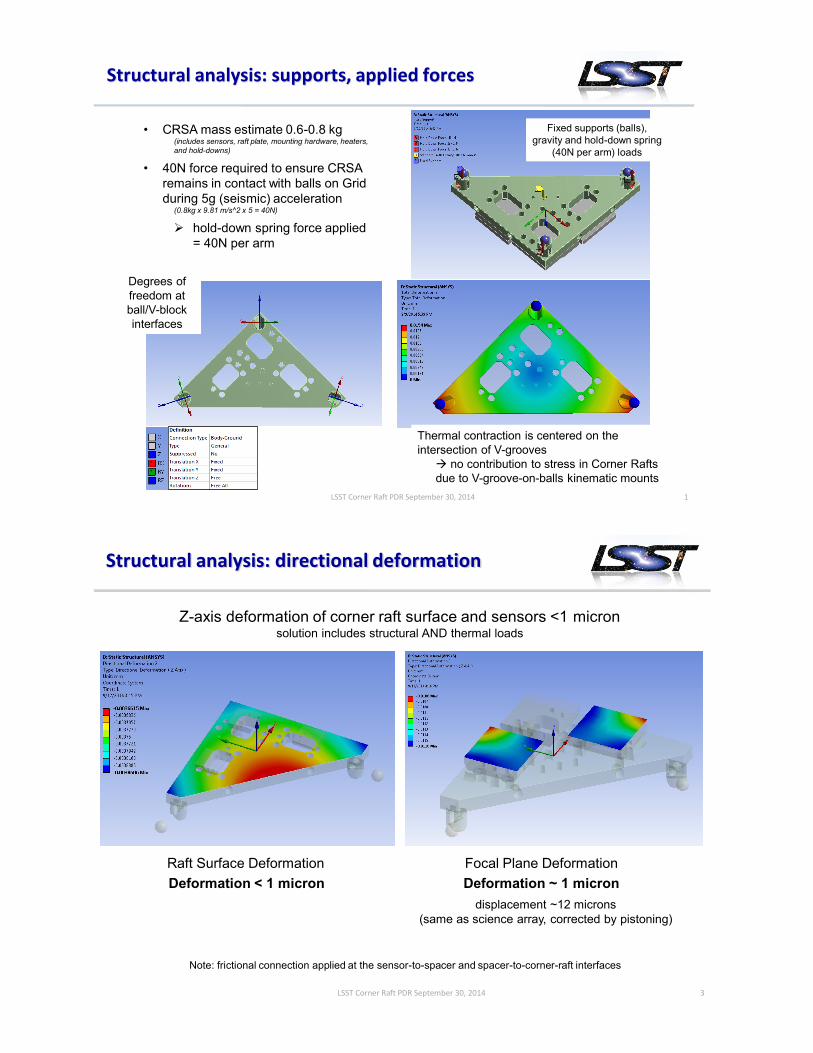
Structural analysis: supports, applied forces
Thermal contraction is centered on the
intersection of V-grooves
no contribution to stress in Corner Rafts
due to V-groove-on-balls kinematic mounts
Fixed supports (balls),
gravity and hold-down spring
(40N per arm) loads
Degrees of
freedom at
ball/V-block
interfaces
• CRSA mass estimate 0.6-0.8 kg(includes sensors, raft plate, mounting hardware, heaters,
and hold-downs)
• 40N force required to ensure CRSA
remains in contact with balls on Grid
during 5g (seismic) acceleration (0.8kg x 9.81 m/s^2 x 5 = 40N)
hold-down spring force applied
= 40N per arm
LSST Corner Raft PDR September 30, 2014 3
Z-axis deformation of corner raft surface and sensors <1 micronsolution includes structural AND thermal loads
Raft Surface Deformation Focal Plane Deformation
Structural analysis: directional deformation
Deformation < 1 micron Deformation ~ 1 micron
displacement ~12 microns
(same as science array, corrected by pistoning)
Note: frictional connection applied at the sensor-to-spacer and spacer-to-corner-raft interfaces
g
r
a
v
i
t
y
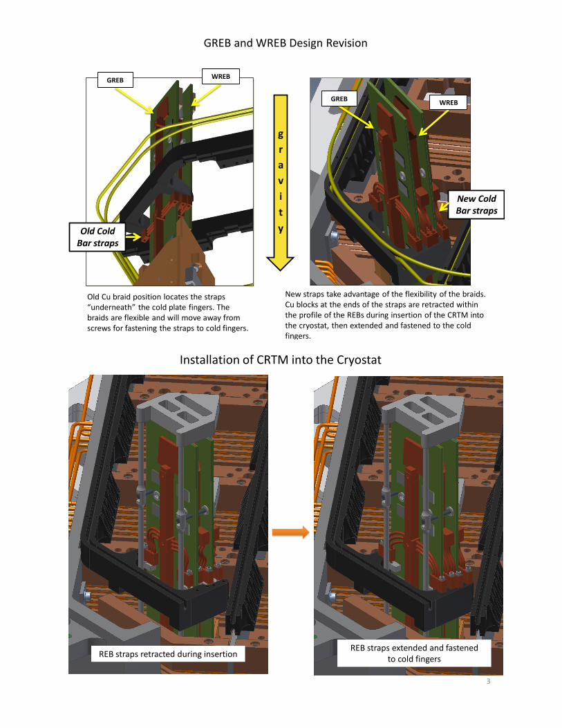
GREB and WREB Design Revision
Old Cold Bar straps
Old Cu braid position locates the straps “underneath” the cold plate fingers. The braids are flexible and will move away from screws for fastening the straps to cold fingers.
New straps take advantage of the flexibility of the braids. Cu blocks at the ends of the straps are retracted within the profile of the REBs during insertion of the CRTM into the cryostat, then extended and fastened to the cold fingers.
WREBGREB
2
WREBGREB
New Cold Bar straps
REB straps retracted during insertion
3
Installation of CRTM into the Cryostat
REB straps extended and fastened to cold fingers
4
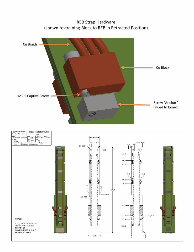
REB Strap Hardware (shown restraining Block to REB in Retracted Position)
Cu Braids
M2.5 Captive Screw
Cu Block
Screw “Anchor” (glued to board)