marcy grinding mills
DESCRIPTION
What is grinding?Just what is grinding? It is the reduction of lump solid materials to smaller particles by the application of shearing forces, pressure, attrition, impact and abrasion. Then, the primary consideration has been to develop some mechanical means for applying these forces. The modern grinding mill applies power to rotate the mill shell and thus transmits energy to some form of media which, in turn, fractures individual particles.TRANSCRIPT
14 1 r 1 ' l ut C\-I~MICAL CORPORAT\ON L35 East 42nd Street New York, N.Y. 10011
-
. ---- -~-.,~-~-~
~ !•c . . " .• • . . • - ... -,~ .
CATAL G 101-B
AN EVOLUTION OF QUALITY PRODUCTS Broad Experience and Years of Development are reflected in the MARCY MILL
For more than fifty yea rs the names MINE AND SMELTER and MARCY have been the symbol of dependable quality ore milling machinery, industr ial and mining equipment, and supplies created for your specific needs. During this period thousands of operators have exper ienced continuous economical and unequalled service through their use .
No exact date is reco rded as to when the need first arose for some mechanical means of reducing particles in size, but considering that it has been many years, it is perhaps surprising that grinding is still an "art" and not an "exact science".
The Mine and Smelter Supply Company, through its Manufacturing Division , during these years has continuously accumulated knowledge on grinding applications. It has contributed greatly to the grinding process through the development and improvement of such equipment.
Just what is grinding? It is the reduction of lump solid materials to smaller particles by the application of sheari'lg forces , pressure , attrition , impact and abrasion . The primary consideration . then , has been to develop some mechanical means for applying these forces . The modern grinding mill applies power to rotate the mill shell and thus transmits energy to some form of media which , in turn , frac tures individual particles.
Just how this can best be done reverts to our history of grinding. In 1914 Mr. Frank E. Marcy established the " Marcy pr inciple of
gri nd ing". This pr inciple is simply stated " rapid change of mill content is necessary for h igh effic iency". This pri nc ip le is incorporated in all Marcy Mills and has been proven in hundreds of operating installations until it is now gene rally accepted as a world-w ide axiom. Since the first Marcy installat ion operators of every class. small as well as large. have shown the ir preference fo r Marcy M ill s. We point with pride to the grea t number of large installations throughout the world where Marcy Mill s are do ing the gri nd ing. Sma ll m ills prof it from the experience of these la rge operations.
Through constant and extensive research . in the field of g rinding as well as in the field of manufacturing. Mine & Smelter cont inues to p ioneer. Constantly changing conditions provide a challenge for the future . Meet ing this challenge keeps our company young and progressive. This progress ive spiri t , with the knowledge gai ned through the years . assures top quality equipment for the users of our mills .
Today Mine & Smelter 's modern manufacturing facilities. rigid controls . and close inspection assure excellence in uniformity of our products and satisfactory performance even under the most severe cond it ions.
You are urged to study the follow ing pages which present a detailed picture of our facilities and d iscuss the techn ical aspects of grinding. You will find th is data helpful when considering the se lection of the grinding equ ipment.
THE MINE AND SMELTER SUPPLY THE ORE & CHEMICAL CORPORATION
235 East 42nd Street New York, N. Y. 10017
El Paso, Texas
Copyright 1958 by The Mine & Smelter Supply Co.
Main Office: Denver 16, Colorado, U .S .A .
3800 Race St. P.O. Box 9041
122 East 42nd St., New York Sal t Lake Ctty, Utah
BOTH MARCY AND MASSCO ARE REGISTER E D T RADEM ARK S Printed in U. S.A.
--
-
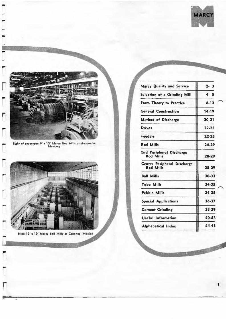
Eight of seve nteen 9 ' x 12' Marcy Rod Mills at Anacondo , Montana
Marcy Quality and Service
Selection of a Grinding Mill
From Theory to Practice
General Construction
Method of Discharge
Drives
Feeders
Rod Mills
End Peripheral Discharge Rod Mills
Center Periphe ral Discharge Rod Mills
Ball Mills
Tube Mills
Pebble Mills
Special Applications
Cement Grinding
Useful Information
Alphabetical Index
2- 3
4- 5
6-13
14-19
20-21
22-23
22-23
24-29
28-29
28-29
30-33
34-35
34-35
36-37
38-39
40-43
44-45
1
OVER SO YEARS OF EXPERIENCE
It is quite understandable that The Mine & Smelter Supply Company takes pride in the quality of its Marcy Mills because of the tradition established and carried forward in the history of our company.
Complementing the human craftsmanship built into these mills, our plants are equipped with modern machines of advanced design which permit accurate manufacturing of each constituent part. Competent supervision encourages close inspection of each mill both as to quality and proper fabrication . Each mill produced is assured of meeting the high required standards. New and higher speed machines have replaced former pieces of equipment to provide up-to-date procedures. The use of high speed cutting and drilling tools has stepped up production , thereby reducing costs and permitting us to add other refinements and pass these savings on to you, the consumer.
Each foundry heat is checked metallurgically prior to pouring. All first castings of any new design are carefully examined by the use of an X-ray machine to be certain of uniformity of structure. The X-ray is also used to check welding work, mill heads, and other castings.
Each Marcy Mill, regardless of size, is designed to meet the specific grinding conditions under which it will be used. The speed of the mill , type of liner, discharge arrangement, size of feeder, size of bearings, mill diameter and length, and other factors are all considered to take care of the size of feed, tonnage, circulating sand load, selection of balls or rods, and the final size of gri nd.
All Marcy Mills are built with jigs and templates so that any part may be duplicated. A full set of detailed drawings is made for each mill and its parts. This record is kept up to date during the life of the mill. This assures accurate duplication for the replacement of wearing parts during the future years.
Views of our manufacturing plant in Denver are shown on these pages. Other manufacturing plants are located in Canada, England, Australia, Sweden, South Africa, and Finland.
MARCY TECHNICA L SERVICE
As a part of our service our staff includes experienced engineers, trained in the field of metallurgy, with special emphasis on grinding work. Th is knowledge, as well as a background gained from intimate contact with various operating companies throughout the world, provides a sound basis for consultat ion on your grind ing problems. We take pride in manufacturi ng Marcy Mills for the metallurgical , rock products, cement, process. and chemical indust ries
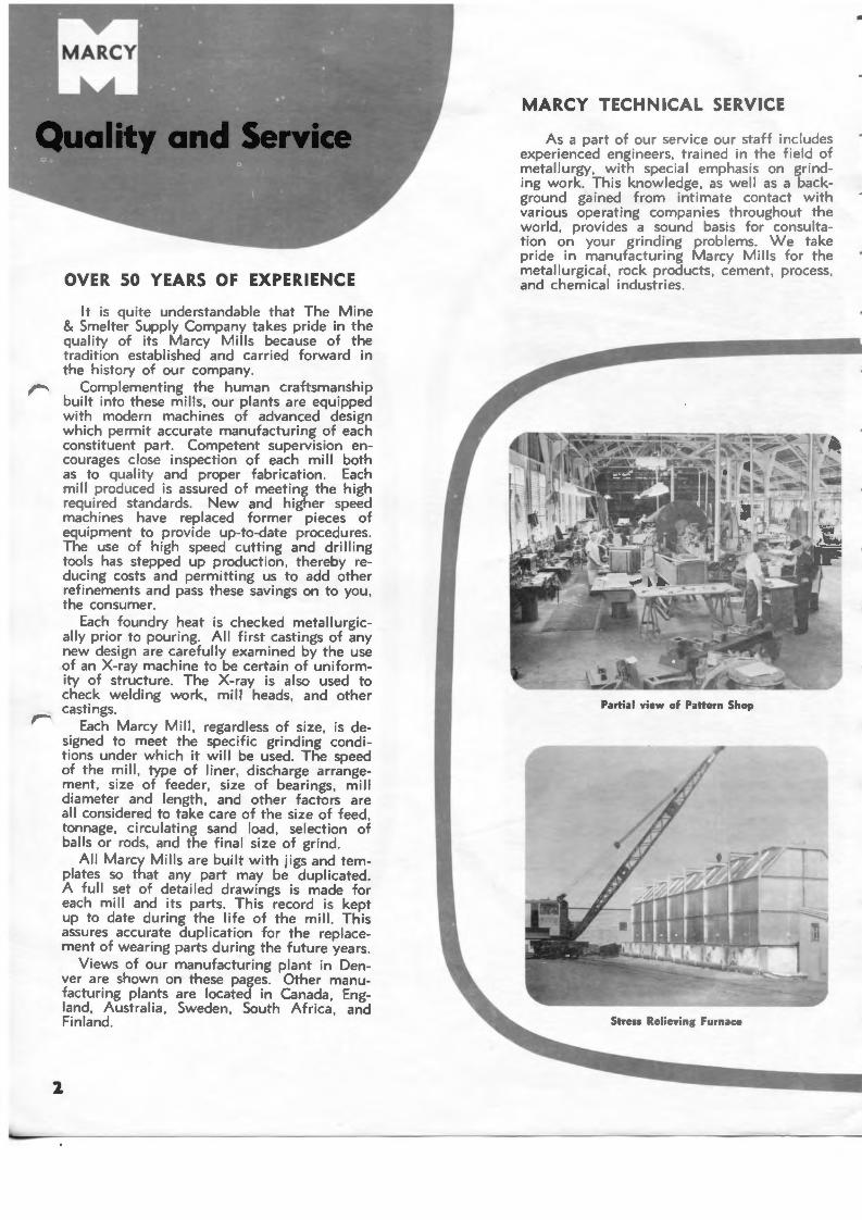
Partial view of Pattern Shop
•
-
-
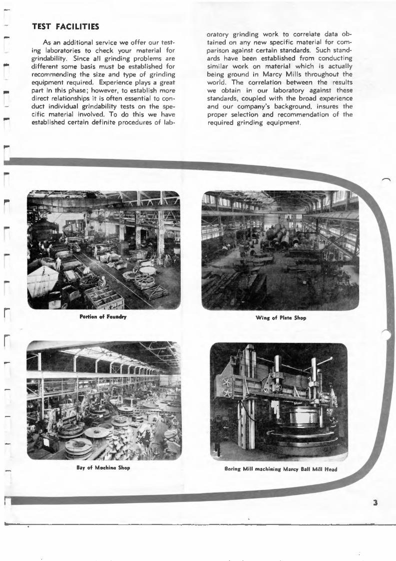
TEST FACI LITIES
As an additional service we offer our testing laboratories to check your material for grindability. Since all grind ing problems are different some basis must be established for recommending the size and type of grind ing equipment required. Experience plays a great part in t h is phase; however, to establish more direct relationships it is often essential to conduct individua l grindability tests on the spec ific material involved. To do this we have established certain definite procedures of lab-
Portion of Foundry
oratory grinding work to correlate data obtained on any new specif ic material for compa rison against certain standards. Such standards have been established from conducting simi lar work on mate rial which is actually being ground in Marcy Mil ls throughout the world. The correlation between the resu lts we obtain in our laboratory against these standards, coupled with the broad experience and our company's background, insures the proper selection and recommendation of the required grinding equipment.
3
4
When selecting a gri nd ing mill there are many factors to be taken into consideration. First let us consider just what constitutes a grinding mill . Essentially it is a revolving, cylindrical shaped machine, the internal volume of which is approxi mately one-half filled with some form of grinding media such as steel balls, rods or non-ferrous pebbles.
Size of feed to a mill may be considered : coarse ( l" to 2"); medium (1/4" to 3/.!"): or fine•(less than 1/4"). Feed may be classified as hard, average or soft. It may be tough , brittle, spongy, or ductile. It may have a high specific gravity or a low specific gravity. The desired product from a mill may range in size from a 4 mesh down to 200 mesh, or into the fine micron sizes. For each of these properties a different mill would be indicated.
The Marcy Mill has been designed to carry out specific grinding work requirements with emphasis on economic factors . Consideration has been given to minimizing shut-down time and to provide long, dependable trouble•free operation. Wherever wear takes place renewable parts have been designed to provide maximum life. A Marcy Mill, given proper care, will last indefinitely.
Marcy Mills have beer manufactured in a wide variety of sizes ranging from laboratory units to mills l2V2' in diameter, w ith any suitable length. Each of these mills, based on the Marcy principle of grinding, provides the most economical grinding apparatus.
Marcy offers you the following advantages:
l . Power requirements and consumption of liners and media are kept at a minimum.
2 . Superior mechanical construction provides continuous low cost operations.
3 . They are available in a large selection of sizes and capacities.
4 . Low pulp level grinding provides an active effective grinding mass within the mill to act on particle size reduction only. There is no wasteful cushioning of grinding action by high pulp levels.
5. For any given capacity, Marcy Low Discharge Level Mills require less floor space, lower transportation costs, and minimum required erection material.
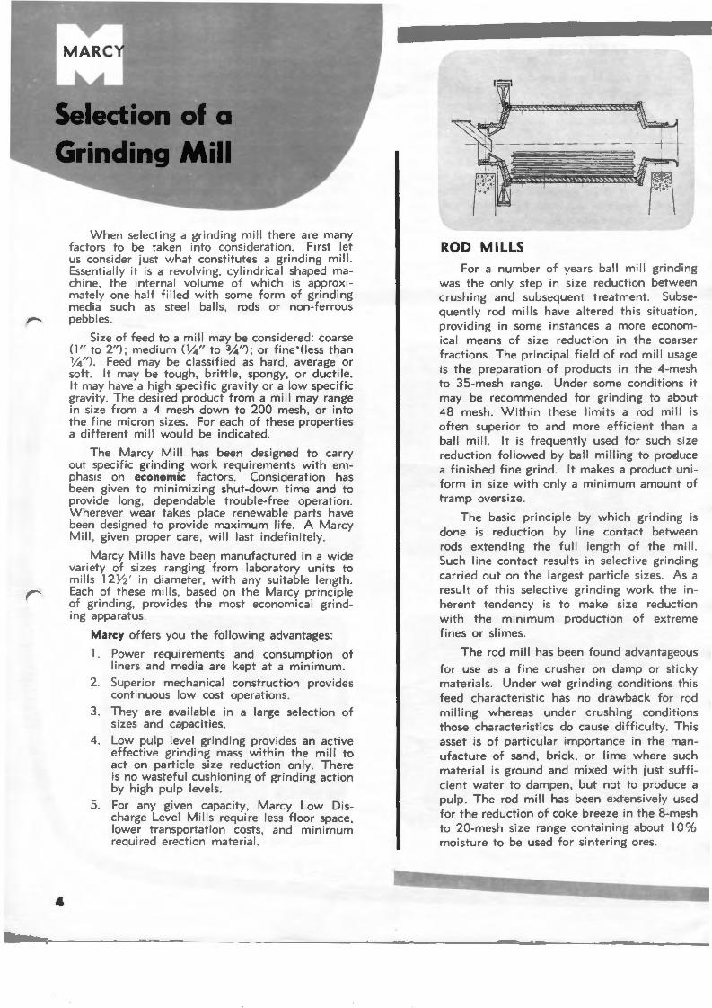
ROD M ILLS For a number of years ball mill grinding
was the only step in size reduction between crushing and subsequent treatment. Subsequently rod mil ls have altered this situation , providing in some instances a more economical means of size reduction in the coarser fractions . The pr incipal f ield of rod mill usage is t he preparation of products in the 4-mesh to 35-mesh range. Under some conditions it may be recommended for grinding to about 48 mesh. Within these limits a rod mill is often superior to and more efficient than a ball mill . It is frequently used for such size reduction followed by ball milling to proE:luce a finished fine grind. It makes a product un iform in size with only a minimum amount of tramp oversize.
The basic principle by which grinding is done is reduction by line contact between rods extending the full length of the m ill. Such line contact results in selective grinding carried out on the largest particle sizes. As a result of th is selective grinding work the inherent tendency is to make s ize reduction with the min imum production of extreme fines or slimes.
The rod mill has been found advantageous
for use as a fine crusher on damp or sticky materials. Under wet grinding conditions this feed characteristic has no drawback for rod mill ing whereas under crushing conditions those characteristics do cause difficulty. Th is asset is of particular importance in the manufacture of sand, brick, or lime where such material is ground and mixed w ith just sufficient water to dampen, but not to produce a pulp. The rod mill has been extensively used for the reduction of coke breeze in the 8-mesh to 20-mesh size range containing about l 0% moisture to be used for sintering ores.
---
-
-
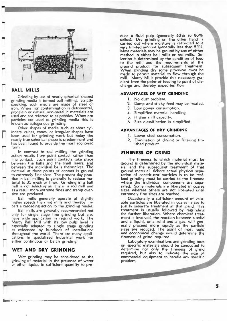
BALL MILLS Grinding by use of nearly spherical shaped
grind ing med ia is termed ball milling. Strictly speaking, such media are made of steel or iron. When iron contamination is detrimental , procel.3in or natura l non-metallic materials are used and are referred to as pebbles. When ore particles are used as grindi ng media this is known as autogenous grinding.
Other shapes of media such as short cylinders, cubes, cones, or irregular shapes have been used for grinding work but today the nearly true spherical shape is predominant and has been found to provide the most economic form .
In contrast to rod milling the grinding action results from point contact rather than li ne contact. Such point contacts take place between the balls and the shell liners, and between the individual balls themselves. The material at those points of contact is ground to extremely fine sizes. The present day practice in ball milling is generally to reduce material to 35 mesh or finer . Grinding in a ball mill is not selective as it is in a rod mill and as a result more extreme fines and tramp oversize are produced.
Ball mills generally operate at slightly higher speeds than rod mills and thereby impart a cascading action to the gri nding media .
Ball mills are genera lly recommended not only for single stage fine gri nd ing but also have wide application in regrind work. The Marcy Ball Mill with its low pulp level is especially adapted to single stage grinding as evidenced by hundreds of installations throughout the world. There are many applications in specialized industrial work for either continuous or batch grinding.
WET AND DRY CRINDINC Wet grinding may be considered as the
grindi ng of material in the presence of water or other liquids in sufficient quantity to pro-
duce a fluid pulp (generally 60 % to 80 % solids) . Dry grinding on the other hand is carried out where moisture is restricted to a very limited amount (generally less than 5 %). Most materials may be ground by use of either method in either ball mills or rod mi lls. Selection is determined by the condition of feed to the mill and the requirements of the ground product for subsequent treatment. When grinding dry some provision must be made to permit material to flow through the mill. Marcy Mills provide this necessary gradient from the point of feed ing to point of discharge and thereby expedites flow.
ADVANTAGES OF WET GRINDING l . No dust problem. 2 . Damp and sticky feed may be treated. 3. Low power consumption. 4 . Simplified material handling. 5 . Higher mill capac ity. 6 . Size classificat ion is simplified.
ADVANTAGES OF DRY GRINDING l. Lower steel consumpti.on . 2 . Elimination of dryi ng or filtering f in
ished product.
FINENESS OF GRIND The fineness to which material must be
ground is determined by the individual material and the subsequent treatment of that ground material. Where actual physical separation of constituent part ic les is to be rea lized grinding must be carr ied to the fineness where the individual components are separated. Some materials are li berated in coarse sizes whereas others are not liberated until extremely fine sizes are reached.
Occasionally a sufficient amount of valuable particles are liberated in coarser sizes to justify separate treatment at that grind. Th is treatment is usually fol lowed by regrind ing for further liberation. Where chemica l treatment is involved , the reaction between a solid and a liquid, or a solid and a gas. will generally proceed more rapid ly as the particle sizes are reduced. The point of most rapid and economica l change would determine the fineness of grind required.
Laboratory examinations and grinding tests on specific materials should be conducted to determine not only the fineness of grind required, but also to indicate the size of commercial equipment to handle any specif ic problem.
5
The fol lowing few pages are devoted to the subject "From Theory to Practice" taking you step by step through some of the variables encountered in grinding and how each of these affect your operations.
As previously pointed out, grinding must still be considered an art and not an exact science. As a result many theories have been expounded on the numerous variables which enter into grinding work. Should it be possible to reduce all of these variables to a simple mathematical formula the selection of a grinding mil l would, of course, be simple. Many approaches to this have been made but to date a fool-proof formula, both mathematically and practically applicable, has not been devised. W e must, therefore, take each variable into consideration on its own merits and then correlate such ideas into a single selection. To do this a broad experience and understanding of the complete subject of grinding is essential. This is a part of the problem of your engineers and our own consulting staff. On page 5 two general points have been discussed briefly — wet or dry grinding, and fineness of grind. Two main categories of grinding equipment, namely rod mills and ball mills, have also been mentioned.
Whether grinding is to be performed wet or dry, or in a ball mil l or rod mi l l , a choice must be made between open or closed circuit. Other factors which require thought are mill size, speed of mil l rotation, moisture content, retention t ime, circulating load, type and sizes of grinding media, mil l pulp level, mil l shape, power, and relation between diameter and length. These all influence operating results and are evaluated and incorporated in the selection and design of the Marcy Mi l l .
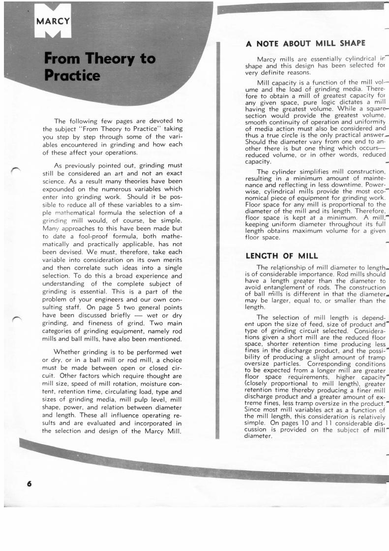
A NOTE ABOUT MILL SHAPE
Marcy mills are essentially cylindrical ir""" shape and this design has been selected for very definite reasons.
Mi l l capacity is a function of the mil l vol — ume and the load of grinding media. Therefore to obtain a mil l of greatest capacity for any given space, pure logic dictates a mil l having the greatest volume. Wh i le a square— section would provide the greatest volume, smooth continuity of operation and uniformity of media action must also be considered and thus a true circle is the only practical answer.— Should the diameter vary from one end to another there is but one thing which occurs— reduced volume, or in other words, reduced capacity. —
The cylinder simplifies mil l construction, resulting in a min imum amount of maintenance and reflecting in less downtime. Power-wise, cylindrical mills provide the most economical piece of equipment for grinding work. Floor space for any mil l is proportional to the diameter of the mil l and its length. Therefore, floor space is kept at a minimum. A m i l l . ~ keeping uniform diameter throughout its ful l length obtains maximum volume for a given floor space.
LENGTH OF MILL The relationship of mil l diameter to length,
is of considerable importance. Rod mills should have a length greater than the diameter to avoid entanglement' of rods. The construction of ball m'ills is dif ferent in that the diameter, may be larger, equal to, or smaller than the length.
The selection of mil l length is dependent upon the size of feed, size of product and ' type of grinding circuit selected. Considerations given a short mil l are the reduced floor space, shorter retention t ime producing less fines in the discharge product, and the possi-' bi l i ty of producing a slight amount of tramp oversize particles. Corresponding conditions to be expected f rom a longer mil l are greater floor space requirements, higher capacity' (closely proportional to mil l length), greater retention t ime thereby producing a finer mil l discharge product and a greater amount of extreme fines, less tramp oversize in the product." Since most mil l variables act as a function of the mil l length, this consideration is relatively simple. On pages 10 and 1 1 considerable discussion is provided on the subject of m i l l " diameter.
6
-
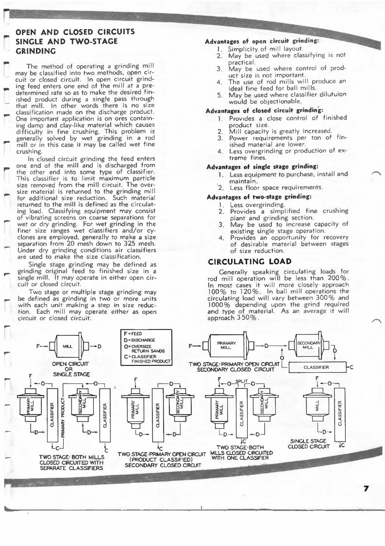
OPEN AND CLOSED CIRCU ITS SINGLE AN D TWO-STAGE GRINDING
The method of operating a grinding mill may be classified into two methods. open circuit or closed circuit. In open circuit grinding feed enters one end of the mi II at a predetermined rate so as to make the desired finished product during a single pass through that mill. In other words there is no size classi f ication made on the discharge product. One important application is on ores contain-
Advantages of ope n circuit grinding: 1. Simplicity of m ill layout. 2 . May be used where classifying is not
practical . 3. May be used where contro l o f prod
uct size is not important. 4 . The use of rod m i l ls will produce an
ideal fine feed for ball mills. 5 . May be used where classi f ier dilutuion
would be objectionable.
Advantages of closed circuit grinding: 1. Prov1des a close control of fin ished
product size. 2 . Mill capacity is greatly increased.
ing damp and clay-like material which causes difficulty in fine crushing. This problem is generally solved by wet grinding in a rod
- mill or in this case it may be called wet fine crushing.
3 . Power requirements per ton of f inished material are lower.
4 . Less overgrinding or production of ext rem e f ines.
--
---
In closed circuit grinding the feed enters one end of the mill and is discharged from the other end into some type of classifier . This class ifier is to limit maximum particle size removed from the mill circuit. The over-size material is returned to the grinding mill for additional size reduction. Such material returhed to the mill is defined as the circulating load. Classifying equipment may consist of vibrating screens on coarse separations for wet or dry grinding. For wet grinding in the finer size ranges wet classifiers and/or cyclones are employed, generally to make a size separation from 20 mesh down to 325 mesh. Under dry grinding conditions air classifiers are used to make the size classification.
Single stage grinding may be defined as grinding original feed to finished size in a single mill . It may o;:>erate in either open circuit or closed circuit.
Two stage or multiple stage grinding may be defined as grinding in two or more uni t s with each unit making a step in size reduction . Each mill may operate either as open circuit or closed c ircuit.
r-0-o F • FEED D : DISCHARGE O =OVERSIZE
RETURN SANDS F-
Advantages of single stage grinding: 1. Less equipment to purchase. install and
maintai n . 2 . Less floor space requirements.
Advantages of two-stage grinding: 1. Less overgrinding. 2. Provides a simpl ified fine crush ing
plan t and grinding section . 3 . May be used to increase capac i ty of
exist ing single stage operation . 4 . Provides an opportunity for recovery
of desirable material between stages of size reduct ion .
CIRCULATING LOAD Generally speaking circulating loads for
rod mi ll operation will be less than 200 %. In most cases it will more closely approach 100% to 120 %. In ball mill operations the ci rcu lat ing load will vary between 300 % and 1000 % depending upon the grind required and t ype of m aterial . As an average i t will app roach 3 50 % .
PRIMARY MILL - D-
t 0
-, D I
OPEN CIRCUIT OR
C =CLASSIFIER FINISHED PRODUCT
Two sTAGE: PRIMARY OPEN CIRCUIT Ll cLAssiFIER Lc SECONDARY CLOSED CIRCUIT '-· ______ ___,!
F SINGLE STAGE
!-o~
W~ ~ iii (/) <{
LD- d
h TWO STAGE: BOTH MILLS CLOSED CIRCUITED WITH SEPARAT E CLASSIFIERS
F I
LD-
lc TWO STAGE:PRIMARY OPEN CIRCUIT
( PRODUCT CLASSIFIED) SECONDARY CLOSED CIRCUIT
F I 0 SPLIT O - --, I ~
LD-IC
T WO STAGE: BOTH MILLS CLOSED CIRCUITED WITH ONE CLASSIFIER
SINGLE STAGE CLOSED CIRCUIT jC
7
From Theory to Practice
MILL SPEEDS Proper speed, or most efficient speed, at
which mills are to operate depends upon the action desired by the grinding media, the amount of media, its size and shape, percentage of solids in each mill , and shape of liners. In the following d iscussion we refer to critical speed applying to ball mills and peripheral speed referring to rod mills. Reference gr~phs giving these speeds for various mill diameters will be found on page 9 .
Critical speed may be considered as the speed at which an infinite particle will continue its travel around the periphery of the mill , thus becoming part of a flywheel action. Grinding balls actually will not centrifuge at th is theoretical critical speed s ince they are larger than an infinite particle and also because of slippage.
The fo llowing table illustrates the action of a normal ba ll charge at various percentages of critical speed.
%Critical Speed 10 20 30 4 0 so 60 70 80 90
Sliding 3 3 3 2 2 2 1 1 Cascading 1 1 1 2 3 3 2
• Centrifuging 1 1 2 2 3 1 indicates slight amount, 2
indicates great amount. indicates appreciable amount, 3
The following table illustrates the effect of va rying the amount of ball charge. Ball Charge 5- 15 15-25 25-35 % (Mill Volume)
Sliding Cascading Centrifuging
* 3 * 3 * * 1
* 2 * * 2 * * 1
35-45
* 1 * 3
** 2
45-50
* 1 * 2 * 3
I indicates sl ight amount, 2 indica tes appreciable amount 3 indicates great amount. '
• effective a t a ll speeds, • * only effect ive a t highe r speeds.
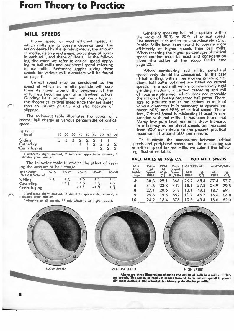
Generally speaking ball mil ls operate within the range of 50 % to 90% of critical speed. The average is found to be approximately 75 % . Pebble Mills have been found to operate more efficiently at higher speeds than ball mills. When reaching the higher percentages of critica l speed caution must be used and consideration given the action of the scoop feeder (see page 22).
When considering rod mills, peripheral speeds only should be considered. In the case of ball milling, with a free moving grinding medium , ball paths obtained are based on critical speeds. ln a rod mill with a comparatively rigid grinding medium, a certain cascading and ro ll of rods are obtained, which does not resemble the action of loosely projected ball paths. Therefore to simulate similar rod actions in mi lls of various diameters it is necessary to operate between 60% and 98% of critical speed. Therefore, Critical Speed is misleading if used in conjunction with rod mi lls. It has been found that Marcy low pulp level rod mills show increases in efficiency as peripheral speeds are increased from 300' per minute to the present practical maximum of around 500' per minute.
To illustrate the comparison between critical speeds and peripheral speeds and the misleading use of critical speed for rod mills, we submit the following illustrative table:
BALL MILLS @ 76% C.S. ROD MILL SPEEDS
M ill Criti- RPM Peri- I At 330' / Min. At 470' / Min. Dia. cal At pheral
Inside Speed 76% Speed Mill % Mi ll % Liners RPM c.s. Ft. / Min. RPM c.s. RPM C.S.
4' 38.3 29. 1 366 26.2 68_4 37.4 97.7 6 31.3 23.8 44? 18. 1 57.8 24.9 79.5 8 27. 1 20.6 518 13. 1 48.3 18.7 69. 1 9 25.6 19.5 552 11.7 45.7 16.6 64.8
10 24.2 18.4 578 10.5 43.4 15.0 62.0
SLOW SPEED MEDIUM SPEED HIGH SPEED
8
Above are three illustrations showing the action of balls in a mill at different speeds. The action at medium speeds (around 75% critical speed) is generally most desirable and efficient for Marcy grate discharge mills.
----
-,.......
--
-
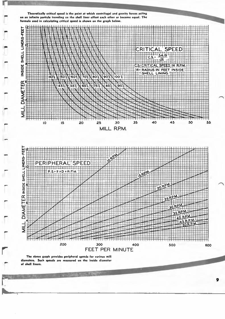
Theoretically critical speed is t he point at wh ich centri fu gal and gravity forces acting on an infinite particle travel ing on the she ll liner offset each other or become equa l. The formula used in calculating crit ical speed is shown on the graph be low.
Zl ::::i .J .J w I: Cl)
w 9 Cl)
z
a::e 40% 0 % 60% 70% 80% 90% 100 %
~ 45% 65% 75% 85% 95%
w ~ <(4 0 _J _J
~
~ Wl2 w La..
J,
~8 ii; ~ a: w t-6 w ~ <(
0 _J4 _J
~
10 15 20 25 30
MILL R.P.M.
PERIPHERA L: SPEED
P. S.= IT X D X R.P. M.
I' I I I
CRITICAL SPEED
Cs = 54.19
. . ..JR .S.= CRITICAL SPE D IN R.P.M. R= RADIUS IN FEET INSIDE
SHELL LINING.
35 40 45
z!:>~P·"" ·
30 Rf>·""·
50
35 R.e·""· 4o R.P.""·
45 R .f>."" · 50 Rf>·"" ·
200 300 400 500
FEET PER MINUTE The above graph provides pe riphera l speeds for various mill
diameters. Such speeds are measured on the inside d iamete r of shell liners.
55
600
9
from Theory to Practice
POWER AND CAPACITY
Often grinding capacity and power are used hand in hand since power is an index to the potent ialities of any grinding mill. The grind achieved is in direct relation to the power applied in rotating a mill. This rotation transmits energy input to the grinding media and energy is consumed in reducing particle sizes. When any particle is split , producing two or more smaller part icles , the total surface area of the smaller particles will be greater than the surface area of the initial size. Therefore surface area often is used to express the amount of grinding work which is performed.
There are two methods of looking at power. First and easily understood is the reference to connected horsepower, or the actual consumed horsepower required to drive the mill. The second is bas ing power on the amount of work done . We prefer to express this as kilowatt hours per ton of materia l ground . The following formula contain ing three factors may be found useful in calculating power consumed per ton of material ground . Wherever two of the factors are available , the third may easily be solved .
KWH/ton x tons per 24 hours 17.9
HP
There are several variables in mill horsepower -the most important has to do with mill diameter. Several of these variables also reflect similarly on capacity. There have been various statements made as to how power and capacity vary with mill diameter , each using a figure of the diameter raised to some power, such as 0 3 , 0 2.65 ,
0 2.6, and 0 2·5. For your convenience we have
listed on page 11 a table givi ng these various diameters raised to the appropriate figures . We have found in the Marcy low pulp level mills that the capacity varies closely as the diameter cubed . The mill power varies closely as the diameter to the 2.5 power . With overflow type mills , or high pulp level mills , the theoretical exponents more closely approach the 2.6 or 2.65 power. The difference lies in the waste of energy when transmitted through a cushioning deep quantity of pulp.
Power required in relationship to m ill length is a straight line function or direct proportion within limits. In other words each foot of m ill will require a definite amount of power. Capacity of a mill also varies in the same manner .
Example:
You are operating a No. 86 Marcy Mill consuming 245 HP and gri nding 500 tons per day to 65 mesh. What will be the capacity of a 54 Marcy Mill? From the table on page 11 . the 86 diameter cubed is 512; the 54 diameter cubed is 125 ; the 86 diameter to the 2.5 power is 181 ; and the 54 diameter to the 2.5 power is 55.91 . Such diameters are inside new liners.
Capacity
125 x4 x 500 = 81 tons
512 X 6
Horsepower
55.91 X 4 X 245 = 50 HP
181 X 6
Therefore the 54 mill will have a capacity of 81 tons and wi II consume 50 H P.
Power consumed is a reflection of the fineness of grind. The finer a material is ground the more power is consumed.
Power consumption is also a reflection of the amount of media carried within the mill. The maximum power requirements for any mill will be when it is 45% to 50 % filled with grinding media . Above or below this power drops off. Similarly mill capacity will behave the same way. Within limits the effect of adding or decreasing grinding media will be proportional to that weight.
Power is again reflected in mill dilution . A mill carrying a high percentage of solids will consume less power than a mill carrying a low percentage of sol ids .
The above refers to wet grinding. Under dry grinding conditions it has been found that the power will be between 60 % and 90 % that of a wet grinding mill. Wet grinding capacity will be 1 Y2 to 2 times that of dry grinding.
-
--
,....
-,....
T ' I I . I . !t-H rl-
3/8"To ,o~:~~rr-=
1 r· , I • ~ - 1-, ' I ..,._ j-r-
3~4J:-il 1/ 7 8 I 10 II 12 ~ I - l ifT! 1- ri-1 !H-I
IO~~~i· Jii/4~"~To~3~5~Mt~sih l r ~ ~ 28 a::c; 26 6 wz >- 24
3 4 5 6 7 8 9 10 II 12 ~ffi 22
I/4"To 150 Mesh
I
9
15
1/2" To 48 Mesh f+
fil~ 20
~~ 18 >- <3 16 a::
1-00 \W
zUl 34587891011
og 1 3 4 5 6 7 8 9 10 II 12 I- u 44 H-L.f-l-
1-1- 42 H\I-
~~ 40
H 1+-l
Ul 38r-- ,.- f-4
11
-
12
'
E 0
0
i 0 1:
1 " ii u w 0
~ 0
'i .... .... :z: ~ ~
II
9
1/2" To 65 Mesh 1- a:: 36 w a.. 34
114" To 200Mesh r ~ :.
17S:SstB:;:JIH::EEE~
15,~~~3/~e·~· T~o ~eo~Mie~sh~rl t
3 4 5 6 7 8 9 10 II 12
32 1-- \ 30 J.--r-28l+c-t- - ~- ... 26 1!- -~ I 24
i I I -f-1 I 8 :~ r-r I 4 f- 4 1" -t- + !
345178tl01112
MILL DIAMETER INSIDE SHELL~Feet
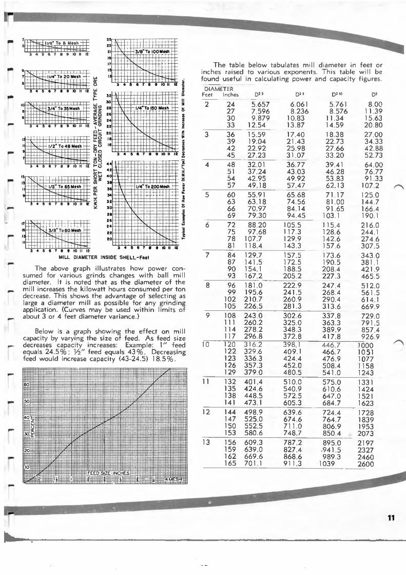
The above graph illustrates how power consumed for various grinds changes with ball mi ll d iameter. It is noted that as the diameter of the mi II increases the kilowatt hours consumed per ton decrease. This shows the advantage of selecting as large a diameter mil l as possible for any grinding application . (Curves may be used within limits of about 3 or 4 feet d iameter variance.)
Below is a graph showing the effect on mill capacity by vary ing the size of feed . As feed size decreases capacity increases : Example : 1" feed equals 24 .5 %: Y2" feed equals 43 %. Decreasing feed would increase capacity (43-24.5) 18.5 %.
~ ~roc
2c
:to · ! FEED: ZE : INC HES i
fit I :j:!'Eff i ~-
The ta bl e be low tabulates mill d ia meter in fee t o r inches raised to various expone nts. Th is table w ill be found useful in calculat ing power and capaci ty f igures .
DIAMETER Fee t Inches
2
3
4
5
6
7
8
9
10
24 27 30 33
36 39 42 45 48 51 54 57
60 63 66 69
72 75 78 81
84 87 90 93
96 99
102 105
108 111 114 117 120 122 123 126 129
11 132 135 138 141
12 144 147 150 153
13 156 159 162 165
D2S D26
5.657 6.061 7.596 8.236 9.879 10.83
12.54 13 .87
15.59 17.40 19.04 21 .43 22.92 25.98 27 .23 31 .07 32.01 36.77 37 .24 43 .03 42.95 49.92 49.18 57.47
--55.91 65 .68 63.18 74 .56 70 .97 84 .14 79 .30 94 .45
88 .20 105.5 97 .68 117.3
107.7 129.9 118.4 143.3 129.7 157.5 141 .5 172.5 154.1 188.5 167.2 205.2
181.0 222.9 195.6 241 .5 210.7 260 .9 226 .5 281.3 243 .0 302.6 260.2 325 .0 278.2 348 3 296 .8 372.8 316 2 398 . 1 329 .6 409 .1 336.3 424 .4 357 .3 452 .0 379.0 480.5 401.4 510.0 424 .6 540 .9 448.5 572.5 473 .1 605 .3 498.9 639 .6 525 .0 674 .6 552.5 711.0 580 .6 748.7 609 .3 787 .2 639.0 827.4 669.6 868 .6 701 .1 911.3
Dl 6S Dl
5.761 8.00 8.576 11 .39
11 .34 15.63 14.59 20 .80
18.38 27 .00 22.73 34 .33 27 .66 42.88 33 .20 52.73
39.41 64 .00 46 .28 76 .77 53 .83 91.33 62.13 107 2 71 .17 125.0 81.00 144.7 91.65 166.4
103.1 190.1
115.4 216 .0 128.6 244 .1 142.6 274 .6 157.6 307.5 173.6 343 .0 190.5 381 .1 208 .4 421 .9 227 .3 465.5 247 .4 512.0 268 .4 56 1.5 290.4 614 . 1 313 .6 669 .9 337 .8 729 .0 363 .3 791.5 389 .9 857 .4 417 .8 926.9 446.7 1000 466.7 1051 476 .9 1077 508 .4 1158 541 .0 1243 575.0 1331 610.6 1424 647 .0 1521 684.7 1623 724.4 1728 764 .7 1839 806 .9 1953 850 .4 2073 895.0 2197
.941 .5 2327 989 .3 2460
1039 2600
From Theory to Practice
GRINDING MEDIA The subject of grinding media is still con
troversial. The following information is general and based upon facts gathered from many operations.
General statements can be made and are worthy of consideration when selecting grinding media . For the best results it has been found that the smallest diameter ball or rod which will break down the particular material to be ground is desirable since greatest surface area is obtained. From the standpoint of economy. the larger the media the higher will be the liner consumption and media consumption . The mini mum size of grinding balls should be selected with caution si nce there will be a tendency for such bal ls to floa t out of the mill in a dense pulp (this is minimized by the use of a Marcy grate di scha'rge mill) . Also the smaller the media the quicker it will reach its reject size .
For the first stage of grinding, media will generally be in the 4" to 2" size (in some cases as high as 5") . In secondary finer grinding the initial charge w ill begin at around 3" and in the case of balls will grade down to about 3_4".
Extremely fine grindi ng will dictate the use of 1 %" and sma ller balls.
Grinding media is the working part of a mill. It will consume power whether it is doing grinding work or not. The amount of work which it does depends upon its size, its material, its construction and the quantity involved . It is, the refore , advantageous to select the type of grinding media which will prove most economical , the size of media which will give the best grinding results , and the quantity of media which will just produce the grind required.
One of the econom ic factors of grinding is the wear of the gr inding media. This is dependent upon the material used in its manufacture, method of manufacture, size of media , diameter of mill , speed of m il l, pulp level maintained in the mill , rate of feed, density of pulp ma inta ined , shape of the liner surface, nature of the feed, and the problem of corrosion .
In general practice , tonnage rates and power consumption will be in direct proportion
11
to the specific gravity of the media and approx imately in direct proportion with the amount of media .
Many shapes of gri nd ing media have been tr ied over the past years . but essentially there are only two efficient types of med ia used . These are the spherical ball and the cylindrical rod . Other shapes are relatively expensive to manufacture and they have shown no appreciable improvement in grinding characterist ics.
It will be found that a seasoned charge will provide a better grind than a new mill charge. This, of course , is impossible to determ ine at the offset, but after continuous operation the media charge should be checked for size and weight, and maintained at that optimum point. After the charge has been selected, replacement media should be made at the maximum size used . In some cases it has been found advantageous to add replacement media of two or more sizes, so as to maintain more closely the seasoned ratio.
The original charge to a mill is generally between 40 % and 50 % of mill volume for ball mills and 35 % to 45 % mill volume for rod mills .
As a general figure rod mills will have a void space within the charge of around 20 % to 22% for new rods. In ball mills the theoretical void space is around 42 % to 43% . It has been found that as grinding rods wear a 4" or 4 Y2" rod will generally break up at about 1 Y2" diameter. The smaller diameter new rods do not break up as easily and will generally wear down to about 1". In many applications it has been found . that grinding efficiency will increase if rods are removed when they reach the 1" size , and also if broken pieces of rods are removed . The Marcy Open End Rod Mill has the advantage of allowing the quick and easy removal of such rods.
It is difficult to give figures on med ia consumption since there are so many var iables. Rods will be consumed at the rate of 0 .2 # per ton on soft easily ground material up to 2 # per ton on harder material. Steel consumption of balls is spread out over an even greater range . Some indication as to media consumption can be obtained from power consumed in grinding. For example , balls or rods will generally wear at a rate of about 1 # for each 6 or 7 kilowatt hours consumed per ton of ore . Liner consumption is generally about one-fifth of the media consumption .
--
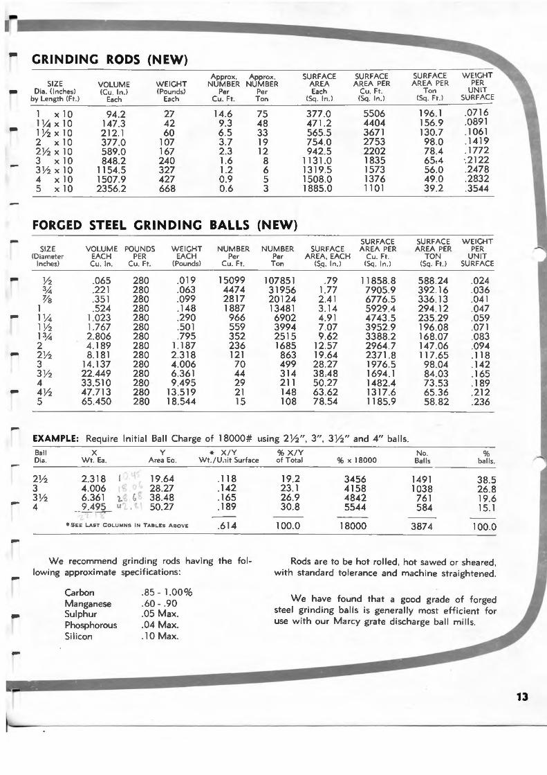
GRINDING RODS (NEW)
SIZE Dia. (Inches)
by Length (Ft.)
1 X 10 11hx 10 1% X 10 2 x10 2% X 10 3 x10 3% X 10 4 x10 5 X 10
VOLUME (Cu. ln .)
Each
94.2 147.3 212.1 377.0 589.0 848.2
1154.5 1507.9 2356.2
WEIGHT (Pounds)
Each
27 42 60
107 167 240 327 427 668
Approx. Approx. NUMBER NUMBER
Per Per Cu. Ft. Ton
14.6 9.3 6.5 3.7 2.3 1.6 1.2 0.9 0.6
75 48 33 19 12
8 6 5 3
SURFACE AREA Each
(Sq. ln.)
377.0 471 .2 565.5 754.0 942.5
1131.0 1319.5 1508.0 1885.0
SURFACE AREA PER
Cu. Ft . (Sq . ln.)
5506 4404 3671 2753 2202 1835 1573 1376 1101
SURFACE AREA PER
Ton <Sq . Ft. l
196.1 156.9 130.7 98.0 78.4 65,4 56.0 49.0 39 .2
WEIGHT PER
UNIT SURFACE
.0716
.0891
.1061
.1419
.1772 ·.2122 .2478 .2832 .3544
FORGED STEEL GRINDING BALLS (NEW)
SIZE <Diameter
Inches)
Y2 3,4 'Va
1 11h 1 Y2 ]3,4 2 2% 3 3% 4 4 Y2 5
VOLUME POUNDS EACH PER Cu. ln . Cu . Ft.
.065
.221
.351
.524 1.023 1.767 2.806 4.189 8.181
14.137 22.449 33 .510 47.713 65.450
280 280 280 280 280 280 280 280 280 280 280 280 280 280
WEIGHT EACH
(Pounds)
.019
.063
.099
.148
.290
.501
.795 1.187 2.318 4.006 6.361 9.495
13.519 18.544
NUMBER Per
Cu . Ft.
15099 4474 2817 1887 966 559 352 236 121 70 44 29 21 15
NUMBE R Pe r
Ton
107851 31956 20124 13481 6902 3994 2515 1685 863 499 314 211 148 108
SURFACE AREA, EACH
<S.q. ln .)
.79 1.77 2.41 3.14 4.91 7 .07 9.62
12.57 19.64 28 .27 38A8 50.27 63 .62 78.54
SURFACE AREA PER
Cu. Ft. (Sq . ln .)
11858.8 7905.9 6776.5 5929 .4 4743 .5 3952.9 3388 .2 2964 .7 2371 .8 1976.5 1694.1 1482.4 1317.6 1185.9
SURFACE AREA PER
TON (Sq . Ft .)
588 .24 392.16 336.13 294.12 235.29 196.08 168.07 147.06 117.65 98.04 84 .03 73 .53 65.36 58.82
WEIGHT PER
UNIT SURFACE
.024
.036
.041
.047
.059
.071
.083
.094
.118
.142
.165
.189
.212
.236
EXAMPLE: Requ ire Initial Ball Charge of 18000# using 2 Y2", 3", 3 Y2" and 4" balls.
Bal l Dia .
X Wt. Ea .
2.318 4.006 6.361 1.~ ~ ~.49_2 u£.,
y Area Eo .
19.64 28.27 38.48 50.27
* SEE LA ST COLUMNS IN TABLES ABOVE
* X / Y Wt. / U.1it Surface
.118
.142
.165
.189
.614
We recommend grindi ng rods having the following approximate specifications:
Carbon Manganese Sulphur Phosphorous Sil icon
. 85- 1.00%
.60- .90
.05 Max.
. 04 Max.
.10 Max.
% X / Y of Total
19.2 23 .1 26.9 30.8
100.0
%X 18000
3456 4158 4842 5544
18000
No. Balls
1491 1038 761 584
3874
% balls.
38.5 26.8 19.6 15.1
100.0
Rods are to be hot rolled , hot sawed or sheared , with standard tolerance and machine straightened .
We have found that a good grade of forged steel grinding balls is generally most efficient for use with our Marcy grate discharge ball m ills .
13
General
The Mine and Smelter Supply Company does not attempt to build a "cheap" grinding mil l . Engineering based on long experience with mill manufacture enters into the production of Marcy Mil ls, wi th the result that in field operation this equipment yields the lowest possible operating costs, maximum operating time, and years of useful service. As such then it is not an expensive mi l l .
Every Marcy Mi l l is engineered and designed to meet the specific grinding conditions under which it wi l l be used. The speed of the mil l , type of liners, grate openings for ball mills, size and type of feeder, size and type of bearings, trunnion openings, mil l d iameter and length, as well as many other smaller factors are all given careful consideration in designing the Marcy Mi l l .
Each mill is of proper design, constructed in a workmanlike manner, and guaranteed to be free from defects in material or workmanship. Al l Marcy Mil ls are built to jigs and templates so any part may be duplicated whenever required. Al l parts are accurately machined for fits wi th close tolerances. Before shipment each mil l is assembled in our shops, carefully checked and match marked to facilitate field erection. The mil l is given a heavy coat of paint especially prepared for this type of machinery and all machined surfaces are thoroughly coated wi th protecting grease.
A complete set of detailed drawings is made for each mill and kept in a fireproof vault. This assures the future supply of perfectly f i t t ing replacement parts for the life of the mil l . Wearing parts embodying the latest developments are supplied on all orders.
Pages 14-19 are devoted to descriptions of many of the integral parts composing a Marcy Mi l l . The discharge parts and the various feeders and drives are discussed on pages 20-23.
In these descriptions you wi l l f ind the word "MEEHANITE". This is a trade name for metal castings poured under a licensed agreement wi th The Meehanite Metal Corporation. A complete description of its characteristics and inherent nature is found on page 19.
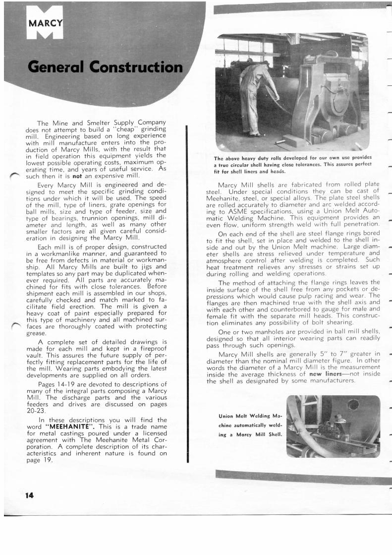
The above heavy duty rolls developed for our own use provides a true circular shell having close tolerances. This assures perfect fit for shell liners and heads.
Marcy Mi l l shells are fabricated from rolled plate steel. Under special conditions they can be cast of Meehanite, steel, or special alloys. The plate steel shells are rolled accurately to diameter and arc welded according to ASME specifications, using a Union Melt Automatic Welding Machine. This equipment provides an even f low, uni form strength weld wi th ful l penetration.
On each end of the shell are steel flange rings bored to f i t the shell, set in place and welded to the shell inside and out by the Union Melt machine. Large diameter shells are stress relieved under temperature and atmosphere control after welding is completed. Such heat treatment relieves any stresses or strains set up during rolling and welding operations.
The method of attaching the flange rings leaves the inside surface of the shell free from any pockets or depressions which would cause pulp racing and wear. The flanges are then machined true wi th the shell axis and wi th each other and counterbored to gauge for male and female f i t w i th the separate mil l heads. This construction eliminates any possibility of bolt shearing.
One or two manholes are provided in ball mil l shells, designed so that all interior wearing parts can readily pass through such openings.
Marcy Mi l l shells are generally 5" to 7 " greater in diameter than the nominal mil l diameter figure. In other words the diameter of a Marcy Mi l l is the measurement inside the average thickness of new liners—not inside the shell as designated by some manufacturers.
Union Melt Welding Ma
chine automatically weld
ing a Marcy Mill Shell.
14
,...
-
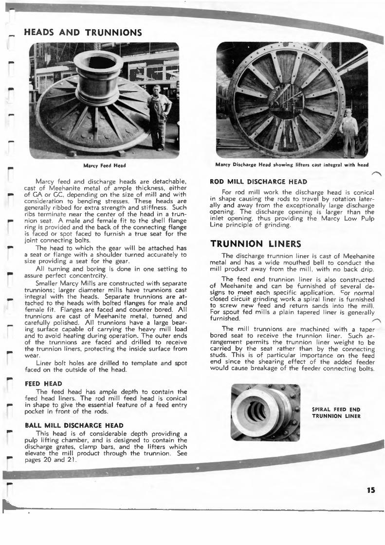
HEADS AND TRUNNIONS
Marcy Feed Head
Marcy feed and discharge heads are detachable. cast of Meehanite metal of ample thickness. either of GA or GC. depending on the size of mill and with cons.i deration to bending stresses. These heads are generally ribbed for extra strength and stiffness. Such ribs terminate near the center of the head in a tru nnion seat. A male and female fit to the shell fla nge ring is provided and the back of the connecting fla nge is faced or spot faced to furnish a true seat for t he joint connecting bolts.
The head to which the gear will be attached has a seat or flange with a shoulder turned accurately to s ize providing a seat for the gear.
All turning and boring is done in one setting to assure perfect concentrcity.
Smaller Marcy Mills are constructed with separate trunnions ; larger diameter mills have trunnions cast integral with the heads. Separate tru nn ions are attached to the heads with bolted flanges for male and female fit . Flanges are faced and counter bored . All trunn ions are cast of Meehanite metal. turned and carefully polished . All trunnions have a la rge bearing surface capable of carrying the heavy mill load and to avoid heating during operation . The outer ends of the trunnions are faced and drilled to receive the trunnion liners. protecting the inside surface from wear.
Liner bolt holes are drilled to template and spot faced on the outside of the head .
FEED HEAD The feed head has ample depth to contain the
feed head liners. The rod mill feed head is con ical in shape to give the essential feature of a feed entry pocket in front of the rods.
BALL MILL DISCHARGE HEAD This head is of considerable depth providing a
pulp lifting chamber, and is designed to contai n the discharge grates, clamp bars . and the lifters which elevate the mill product through the trunnion . See pages 20 and 21 .
Marcy Discharge Head showing lifters cast integral w ith head
ROD MILL DISCHARG E HEAD
For rod mill work the discharge head is conical in shape causing the rods to travel by rotation laterally and away from the exceptionally large discharge opening. The discharge opening is larger than the in let opening. thus providing the Marcy Low Pulp Line principle of grinding.
TRUNNION LIN ERS The discharge trunn ion liner is cast of Meehan ite
metal and has a wide mouthed bell to conduct the m ill product away from the mill . with no back dr ip .
The feed end trunn ion liner is also constructed of Meehan ite and can be furnished of several designs to _meet each specific application . cor normal closed circu it gri nd ing work a spiral liner is furn ished to screw new feed and return sands into the mill. For spout fed mills a plain tapered liner is generally furn ished . ~
The mill trunnions are machined with a taper bored seat to receive the trunn ion liner. Such arrangement permits the trunnion liner wei ght to be carried by the seat rather than by the connecting studs . Th is is of particular importance on the feed end since the shearing effect of the added feeder would cause breakage of the feeder connecting bolts.
SPIRAL FEED END TRUNNION LINER
15
General Construction
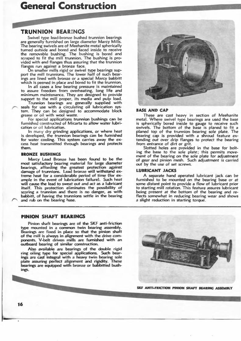
TRUNNION BEARI CS Swivel type lead-bronze bushed trunnion bearings
a re generally furnished on large diameter Marcy Mills. The bearing swivels are of Meehanite metal spherically turned outside and bored and faced inside to receive the removable bushing. The bushing is bored and scraped to fit the mill trunnion. The bushing is provided with end flanges thus assuring that the trunnion flanges run against a bronze face.
On smaller mills rigid or swivel type bearings support the mill trunnions. The lower half of such bearings are lined with bronze or a special Marcy babbitt which is peened in place and bored to fit the trunnion.
In all cases a low bearing pressure is maintained to assure freedom from overheating, long life and minimum maintenance. They are designed to provide support to the mill proper, its media and pulp load.
Trunnion bearings are generally supplied with seals for use with a circulating oil lubrication system. They can be designed to accommodate block grease or oi I with wool waste.
For special applications trunnion bushings can be furnished c-onstructed of Micarta to allow water lubrication or oi l lubrication.
In mdny dry grinding applications, or where heat is developed, the trunnion bearings can be furnished for water cooling. This system carries away the excess heat transmitted through bearings and protects them.
BRONZE BUSHINCS Marcy Lead Bronze has been found to be the
most satisfactory bearing material for large diameter bearings, affording the greatest protection against damage of trunnions. Lead bronze wi ll w ithstand extreme heat for a considerable period of time (for example in the event of lubrication failure). Such heat will cause the lead to sweat out and act as a lubricant itself. This protection eliminates the possibility of scoring a trunnion and there is no danger, as with babbitt, of having the trunnions settle in the bearing and rub on the bearing l>ase.
PINION SHAFT BEARINGS Pinion shaft bearings are of the SKF anti-friction
type mounted in a common twin bearing assembly. Bearings are fixed in place so that the pinion shaft of the mill is always in alignment with the drive components. V-belt driven mills are furnished with an outboard bearing of similar construction.
Also available are bearings of the double rigid ring oiling type for special applications. Such bearings are cast integral with a heavy twin bearing sole plate assuring perfect alignment and rigidity. These bearings are equipped with bronze or babbitted bushings.
16
BASE AND CAP These are cast heavy in section of Meehanite
metal. Where swivel type bearings are used the base is spherically bored inside to gauge to receive such swivels. The bottom of the base is planed to fit a planed top of the trunnion bearing sole plate. The bearing cap is provided with a shroud feature extending out over drip flanges to protect the bearing from entrance of dirt or grit.
Slotted holes are provided in the base for bolting the base to the sole plate ; this permits movement of the bearing on the sole plate for adjustment of gear and pinion mesh. Such adjustment is carried out by the use of set screws.
LUBRICANT JACKS A separate hand operated lubricant jack can be
furnished to be mounted on the bearing base or at some distant point to provide a flow of lubricant prior to starting mill rotation. This feature assures lubricant being present at the bottom of the bearing and reflects somewhat in reducing bearing wear and shows a slight reduction in starting torque.
....
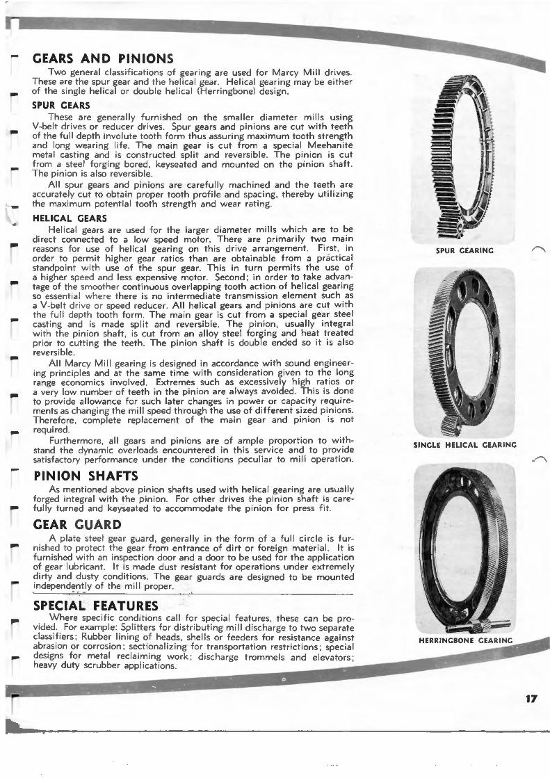
GEARS AND PINIONS Two general c lassifications of geari ng are used for Marcy Mill drives .
These are the spur gear and the helical gear. Helica l gearing may be either of the single helical or double helical (Her ringbone) design .
SPUR GEARS These are genera lly furn ished on the smaller diameter mil ls using
V-belt drives o r reducer drives . Spur gears and pinions are cut with teeth of the ful l depth involute tooth form thus assuring maximum tooth strength and long wear ing life. The main gear is cut from a special Meehanite metal casting and is constructed split and revers ible . The pinion is cut from a steel forging bored, keyseated and mounted on the pinion shaft. The pinion is also reversible .
All spur gears and pinions are careful ly machined and the teeth are accurately cut to obta in proper tooth profile and spacing. thereby util izing the maximum potential tooth strength and wear rating.
HELICAL GEARS Helical gears are used for the larger diameter mills which are to be
direct connected to a low speed motor. There are primarily two ma in reasons fo r use of helical gearing on this drive arrangement . First. in order to permit h igher gear ratios than are obtai nable from a practical standpoint w ith use of the spur gear. This in turn permits the use of a higher speed and less expensive motor. Second ; in order to take advantage of the smoothe r continuous overlapping tooth action of helical geari ng so essent ial where the re is no intermediate transmission element such as a V-belt drive or speed reducer . All helical gears and pinions are cut with the fu ll depth tooth form . The main gear is cut from a special gear steel cast ing and is made split and reversible . The pinion , usually integral with the pinion shaft , is cut from an alloy steel forging and heat treated prior to cutting the teeth . The pinion shaft is double ended so it is also reversible .
All Marcy Mill geari ng is designed in accordance with sound engineering princ iples and at the same time w ith consideration gi ven to the long range economics involved . Extremes such as excessively high ratios or a very low number of teeth in the pin ion are always avoided . Th is is done to provide allowance for such later changes in power or capacity requirements as changing the m ill speed through the use of different sized pinions. Therefore , complete repl acement of the main gea r and pinion is not required .
Furthermore , all gears and pinions are of ample proportion to withstand the dynamic overloads encountered in this service and to provide sat isfactory performance under the conditions peculiar to mill operation .
PINION SHAFTS As mentioned above pin ion shafts used with helical geari ng are usua lly
forged integral with the pinion . For other drives the pin ion shaft is carefully turned and keyseated to accommodate the pin ion for press f it .
GEAR GUARD A p late steel gear gua rd , generally in the form of a full ci rcle is fur
nished to protect the gear from entrance of dirt or forei gn material. It is furnished w ith an inspecti on door and a door to be used for the application of gear lubr icant. It is made dust resista nt for operations under extremely dirty and dusty condi t ions. The gear guards are designed to be mounted independently of the mill proper.
SPECIAL FEATURES Where spec ific cond itions call for specia l features . these can be pro
vided . For example : Splitters for d istri but ing m ill d ischarge to two separate classi fiers ; Rubber lining of heads , shells or feeders fo r resistance agai nst abrasion or corrosion; sectionalizing for transportation restrictions ; special
"""' designs for metal reclaiming work ; discharge trammels and elevators ; heavy duty scrubber applications.
SPUR GEARING
SINGLE HELICAL GEARING
17
General Construction
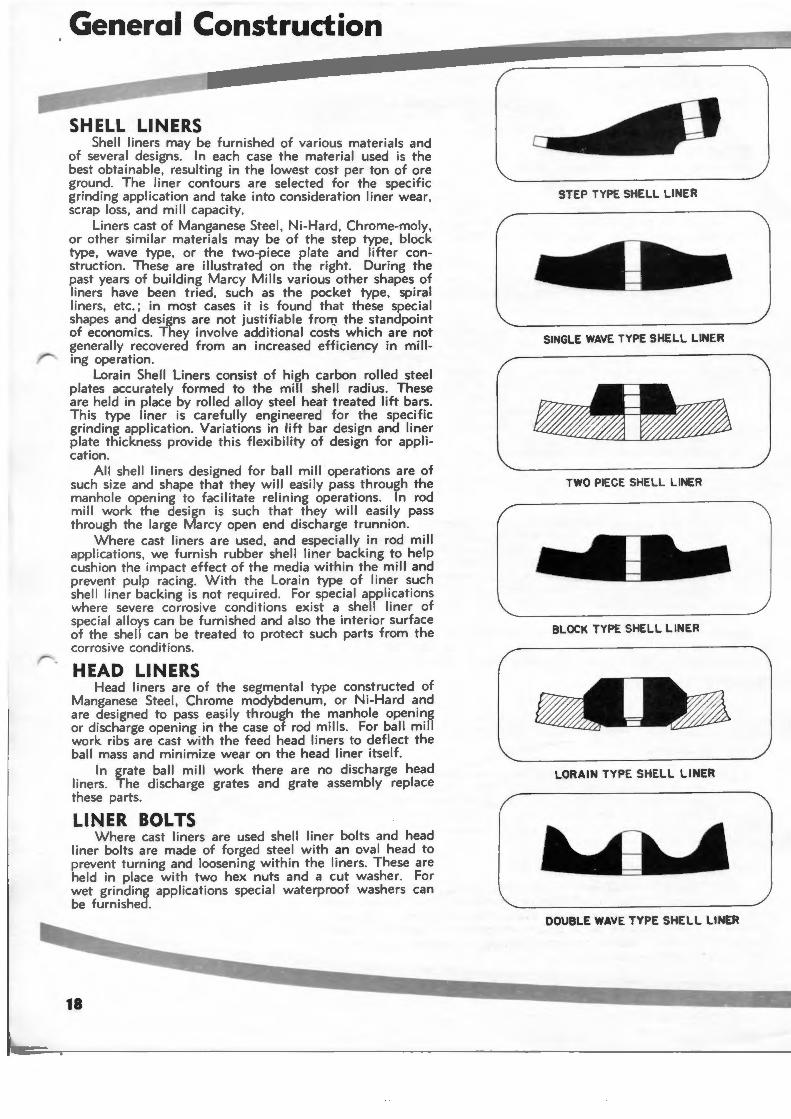
SHELL LINERS Shell liners may be furnished of various materials and
of several designs. In each case the material used is the best obtainable , resulting in the lowest cost per ton of ore ground. The liner contours are selected for the specific grinding application and take into consideration liner wear, scrap loss, and mill capacity.
Liners cast of Manganese Steel, Ni-Hard, Chrome-moly, or other similar materials may be of the step type, block type , wave type, or the two-piece plate and lifter construction. These are illustrated on the right. During the past years of building Marcy Mills various other shapes of liners have been tried, such as the pocket type, spiral liners, etc.; in most cases it is found that these special shapes and designs are not justifiable frorry the standpoi nt of economics. They involve additional costs which are not generally recovered from an increased efficiency in milling operation.
Lorain Shell Liners consist of high carbon rolled steel plates accurately formed to the mill shell radius. These are held in place by rolled alloy steel heat treated lift bars. This type liner is carefully engineered for the specific grinding application. Variations in lift bar design and liner plate thickness provide this flexibility of design for application .
All shell liners designed for ball mill operations are of such size and shape that they will easily pass through the manhole opening to facilitate relining operations. In rod mill work the design is such that they will easily pass through the large Marcy open end discharge trunnion .
Where cast liners are used, and especially in rod mill appl ications, we furnish rubber shell liner backing to help cush ion the impact effect of the media within the mill and prevent pulp racing. With the Lorain type of liner such she ll liner backing is not required . For special applications where severe corrosive cond itions exist a shell I iner of special alloys can be furnished and also the interior surface of the shell can be treated to protect such parts from the corrosive conditions.
HEAD LINERS Head liners are of the segmental type constructed of
Manganese Steel , Chrome modybdenum, or Ni-Hard and are des igned to pass easily through the manhole opening or discharge opening in the case of rod mills. For ball mill work ribs are cast with the feed head liners to deflect the ball mass and minimize wear on the head liner itself.
In grate ball mill work there are no discharge head liners. The discharge grates and grate assembly replace these parts.
LINER BOLTS Where cast liners are used shell liner bolts and head
liner bolts are made of forged steel with an oval head to prevent turning and loosening within the liners. These are held in place with two hex nuts and a cut washer. For wet grinding applications special waterproof washers can be furnished .
18
STEP TYPE SHELL LINER
SINGLE WAVE TYPE SHELL LINER
TWO PIECE SHELL LINER
BLOCK TYPE SHELL LINER
LORAIN TYPE SHELL LINER
DOUBLE WAVE TYPE SHELL LINER
....
-
....
-
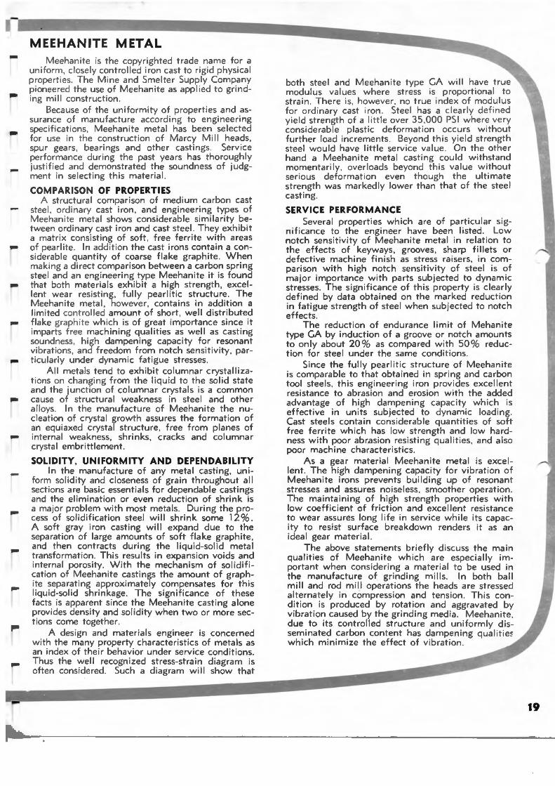
MEEHANITE METAL Meehanite is the copyrighted trade name for a
uniform , closely controlled iron cast to ri gid physical properties . The Mine and Smelter Supply Company pioneered the use of Meehanite as applied to gri nding mi II construction.
Because of the uniformity of properties and assurance of manufacture according to engineering specifications, Meehanite metal has been selected for use in the construction of Marcy Mill heads , spur gears. bearings and other castings. Service performance during the past years has thoroughly justified and demonstrated the soundness of judgment in selecting this material .
COMPARISON OF PROPERTIES A structural comparison of medium carbon cast
stee l, ordina ry cast iron , and eng ineering types of Meehanite metal shows considerable similarity between ord inary cast iron and cast steel. They exhibit a matr ix consisting of soft , free ferrite with areas of pearl ite . In addition the cast irons contain a considerable quantity of coarse flake graphite. When making a direct comparison between a carbon spring steel and an engineering type Meehanite it is found that both materials exhibit a high strength , excellent wear res isting, fully pearlitic structure. The Meehan ite metal, however, contains in addition a limited contro lled amount of short, well distributed flake graphite which is of great importance since it imparts free machining qualities as well as casting soundness , high dampening capacity for resonant vibrat ions , and freedom from notch sensitivity , particularly under dynamic fatigue stresses.
All meta ls tend to exhibit columnar crystallizations on changi ng from the liquid to the solid state and the junction of columnar crystals is a common cause of structural weakness in steel and other alloys. In the manufacture of Meehanite the nucleation of crystal growth assures the formation of an equiaxed crystal structure , free from planes of internal weakness, shrinks, cracks and columnar crystal embrittlement .
SOLIDITY, UNIFORMITY AND DEPENDABILITY In the manufacture of any metal casting, uni
form solidity and closeness of grain throughout all sections are basic essentials for dependable castings and the el imination or even reduction of shrink is a major problem with most metals. During the process of solidification steel will shrink some 12% . A soft gray iron casting wi II expand due to the separation of large amounts of soft flake graphite, and then contracts during the liquid-solid metal transformation . This results in expansion voids and internal porosity. With the mechanism of solidification of Meehanite castings the amount of graphite separating approximately compensates for this liquid-soli d shrinkage . The significance of these facts is apparent since the Meehanite casting alone provides density and solidity when two or more sections come together.
A design and materials engineer is concerned with the many property characteristics of metals as an index of their behavior under service conditions . Thus the well recognized stress-strain diagram is often cons ide red . Such a diagram wi II show that
both steel and Meehanite type GA w ill have true modulus values where stress is proportional to strain . There is , however . no true index of mod ulus for ordinary cast iron . Steel has a cl early def ined yie ld strength of a little ove r 35 ,000 PSI where very considerable pla stic deformation occurs without further load increments. Beyond this yield strength steel would have little service value . On the other hand a Meehanite metal casting could withstand momentarily, overloads beyond th is value without serious deformation even though the ultimate strength was markedly lower than that of the steel casting.
SERVICE PERFORMANCE Several properties which are of particular sig
nificance to the engineer have been listed . Low notch sensitivity of Meehanite metal in relation to the effects of keyways. grooves, sharp fillets or defective machine finish as stress raisers . in comparison with high notch sensitivity of steel is of major importance with parts subjected to dynamic stresses. The significance of this property is clearly defined by data obtained on the marked reduct ion in fatigue strength of steel when subjected to notch effects.
The reduction of endurance limit of Mehanite type GA by induction of a groove or notch amounts to only about 20% as compared with 50 % reduction for steel under the same conditions.
Since the fully pearlitic structure of Meehanite is comparable to that obtained in spring and carbon tool steels, this engineering iron provides excellent resistance to abrasion and erosion with the added advantage of high dampening capacity which is effective in units subjected to dynamic loading. Cast steels contain considerable quantities of soft free ferrite which has low strength and low hardness with poor abr.asion resisting qualities , and also poor machine characteristics.
As a gear material Meehanite metal is excellent. The high dampening capacity for vibration of Meehan ite irons prevents building up of resonant stresses and assures noiseless, smoother operation . The maintaining of high strength properties with low coefficient of friction and excellent resistance to wear assures long life in service while its capacity to resist surface breakdown renders it as an ideal gear material.
The above statements briefly discuss the main qualities of Meehanite which are especially important when considering a material to be used in the manufacture of grinding mills . In both ball mill and rod mill operations the heads are stressed alternately in compression and tension . This condition is produced by rotation and aggravated by vibration caused by the grinding media . Meehanite , due to its controlled structure and uniformly disseminated carbon content has dampen ing qualitieo which minimize the effect of vibrat ion .
19
The Marcy Principle of Grinding-"Rapid change of mill content is necessary for high efficiency."
Marcy Mills have a very large discharge opening or area and smaller area for incoming feed. The gradient between the incoming feed opening and the discharge near the periphery of the shell provides a faster mi-
/"'a t ion of the fines than the oversize particles. In ~eep pulp level mills commonly known as "overflow mills" this migration can not occur since material enters and leaves at the same level by displacement only. Independent tests have shown that regardless of mi II shape or design , the discharge product of an overflow mill will be the same no matter at which end the feed enters.
Marcy low pulp mills benefit from the full impact of the grinding media acting on the ore particles, as it falls into the shallow pulp . With a deep pulp level t~e grinding media is cushioned in the pulp, thus losing its energy and reducing its grinding ability. Marcy Mills have shown 25% to 45% more tonnage ground and a substantial reduction in power consumed per ton of material compared size for size with overflow mills.
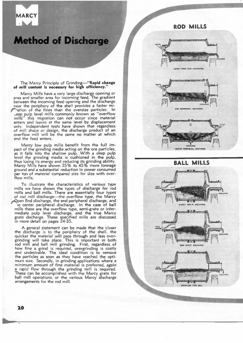
To illustrate the characteristics of various type mills we have shown the types of discharge for rod mills and ball mills. There are essentially four types of rod mill discharge-the overflow type , the Marcy
,rOpen End discharge, the end peripheral discharge , and 1e center peripheral discharge. In the case of ball
mills these are the overflow type, semi-grate or intermediate pulp level discharge , and the true Marcy grate discharge. These specified mills are discussed in more detail on pages 24-35.
A general statement can be made that the closer the d ischarge is to the periphery of the shell, the quicker the material will pass through and less overgrinding will take place. This is important in both rod mill and ball mill grinding. First, regardless of how fine a grind is required , overgrinding is costly and undesirable. The ideal condition is to remove the particles as soon as they have reached the optimum size. Secondly, in grinding applications where a minimum amount of fine material is prefe rred , again a rapid flow through the grinding mill is required . These can be accomplished with the Marcy grate for ball mill operations, or the various Marcy discharge arrangements for the rod mill.
2.0
ROD MILLS
MARCY OPE,.., END DISCHARGE
END PERtPHERAl DISOV.AG£
CENTER PEfUPH(RAL. DISCHARGE
BALL MILLS
l.AARCY GRATE CMSCHA.RGE
SEMI GAATE DISCHARG E
~ OISCHAA<Z
r · 1 OVERFLOW TYPE • MIU
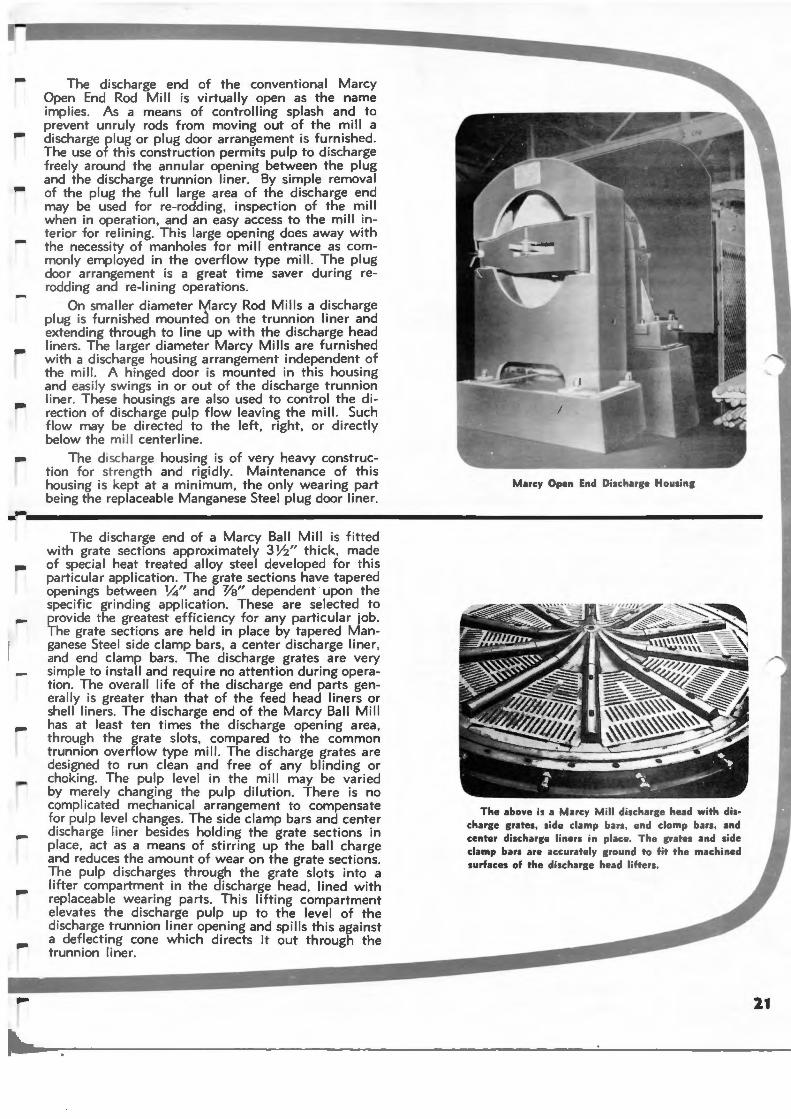
- The discharge end of the conventional Marcy Open End Rod Mill is virtually open as the name implies. As a means of controlling splash and to prevent unruly rods from moving out of the mill a discharge plug or plug door arrangement is furnished . The use of th is construction permits pulp to discharge freely around the annular opening between the plug and the discharge trunnion liner. By simple removal of the plug the full large area of the discharge end may be used for re-rodding, inspection of the mill when in ope ration , and an easy access to the mill interior for relining. This large opening does away with the necessity of manholes for mill entrance as commonly employed in the overflow type mill. The plug door arrangement is a great time saver during rerodding and re- lining operations.
On sma lle r diameter tylarcy Rod Mills a discharge plug is furnished mounted on the trunnion liner and extending through to line up with the discharge head liners . The larger diameter Marcy Mills are furnished with a discha rge housing arrangement independent of the mill. A hinged door is mounted in this housing and easily swi ngs in or out of the discharge trunnion liner. These housings are also used to control the di rection of discharge pulp flow leaving the mill. Such flow may be di rected to the left. right, or directly below the mi ll centerline.
The d ischarge housing is of very heavy construct ion for strength and rigidly. Maintenance of this housing is kept at a minimum, the only wearing part being the replaceable Manganese Steel plug door liner.
Marcy Open End Discharge Housing
-- ·----------------------------------------------------------------------------------------------------
-
-
The d ischarge end of a Marcy Ball Mill is f itted with grate sections approximately 3 Y2" thick, made of special heat treated alloy steel developed for this part icular application. The grate sections have tapered openings between 1/.1" and Ya" dependent upon the specific grind ing application. These are selected to provide the greatest efficiency for any particular job. The grate sections are held in place by tapered Manganese Steel side clamp bars, a center discharge liner, and end clamp bars. The discharge grates are very simple to install and require no attention during operation . The overall life of the discharge end parts genera lly is greater than that of the feed head liners or shell liners. The discharge end of the Marcy Ball Mill has at least ten times the discharge opening area, through the grate slots, compared to the common trunn ion overflow type mill. The discharge grates are designed to run clean and free of any blinding or choking. The pulp level in the mill may be varied by merely changing the pulp dilution. There is no compli cated mechanical arrangement to compensate for pulp level changes. The side clamp bars and center discharge liner bes ides holding the grate sections in place , act as a means of stirring up the ball charge and reduces the amount of wear on the grate sections. The pulp discharges through the grate slots into a lifter compartment in the discharge head , lined with replaceable wearing parts. This lifting compartment elevates the discharge pulp up to the level of the d ischarge trunnion liner opening and spills this against a deflecting cone which directs it out through the trunn ion liner.
The above is a Marcy Mill discharge head with d ischarge grates, side clamp bars, end clomp bars, and center discharge li ne rs in place. The grates and side clamp bars are accurately ground to fit the machined surfaces of the discha rge head lifters.
2.1
Drives and Feeders
Several types of drives can be furnished, made up of various combinations of gearing, motors and transmission equipment. The correct combination to be selected takes into consideration power requirements , gear ratings, floor space, interference from other plant equipment and motor characteristics. The ma in types are described and illustrated on these pages.
Motors considered are the squirrel cage motor, wound rotor motor, and synchronous motor. One important advantage of the synchronous motor is the possible correcting of power factor within your operation , through its use. When using a synchronous motor we recommend having 200% starting torque, 120% to 130% pull-i n to rque , and 225 % pull-out torque. These assume no greater than a 1 0 % voltage drop at the motor term inals.
FEEDERS Each application dictates the selection of proper feed
ing arrangement. This depends upon whether the grinding will be open circu it or closed circuit, and dry grinding or wet gri nding. The size of feed and tonnage rates are also important factors.
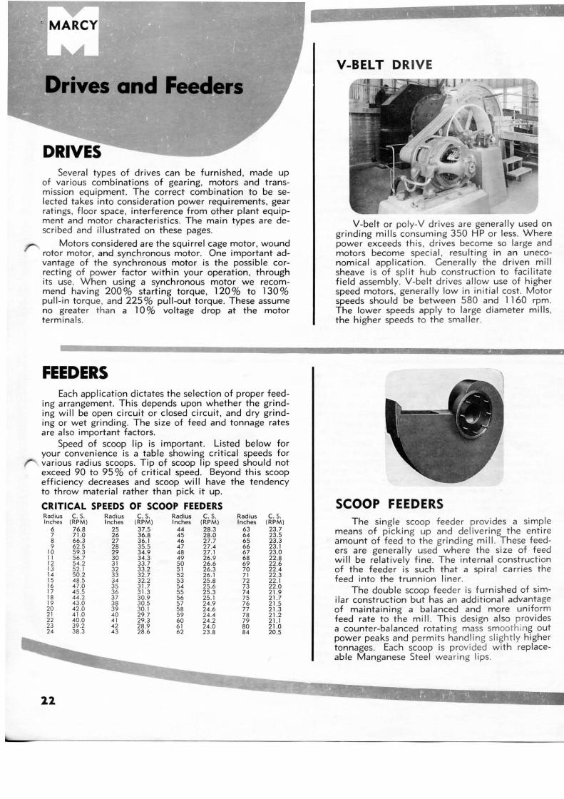
Speed of scoop lip is important. Listed below for your convenience is a table showing critical speeds for various radius scoops. Tip of scoop lip speed should not exceed 90 to 95% of critical speed. Beyond this scoop efficiency decreases and scoop will have the tendency to throw material rather than pick it up.
CRITICAL SPEEDS OF SCOOP FEEDERS Radius Inches
6 7 8 9
10 11 12 13 14 15 16 17 18 19 20 21 22 23 24
2.2
c. s. (RPM)
76.8 71.0 66.3 62.5 59.3 56.7 54.2 52.1 50.2 48 .5 47 .0 45.5 44.2 43.0 42.0 41.0 40.0 39.2 38.3
Radius Inches
25 26 27 28 29 30 31 32 33 34 35 36 37 38 39 40 41 42 43
c. 5. (RPM) 37.5 36.8 36.1 35.5 34.9 34.3 33.7 33.2 32.7 32.2 31.7 31.3 30.9 30.5 30.1 29.7 29.3 28 .9 28 .6
Radius Inches
44 45 46 47 48 49 50 51 52 53 54 55 56 57 58 59 60 61 62
c. 5. (RPM) 28 .3 28.0 27.7 27.4 27.1 26.9 26.6 26.3 26.1 25.8 25.6 25.3 25.1 24.9 24 .6 24 .4 24.2 24 .0 23.8
Rad ius Inches
63 64 65 66 67 68 69 70 7 1 72 73 74 75 76 77 78 79 80 84
c. 5. (RPM ) 23.7 23.5 23.3 23.1 23.0 22.8 22.6 22.4 22.3 22.1 22.0 21.9 21.7 21.5 21.3 21.2 21.1 21.0 20.5
~-~~~ • • \'I • . '' ' 'ft~- ·. _ .. ·r»~P~-~....-,~~-£:"~J._ . ..._1-'- ' ' .. t
V-BEL T DRIVE
V-belt or poly-V drives are generally used on grinding mills consuming 350 HP or less. Where power exceeds this , drives become so large and motors become spec ial , resulting in an uneconom ical applicat ion . Generally the driven mill sheave is of split hub construction to facilitate field assembly. V-belt drives allow use of higher speed motors , generally low in initial cost. Motor speeds should be between 580 and 1160 rpm. The lower speeds apply to large diameter mills , the higher speeds to the smaller.
SCOOP FEEDERS The single scoop feede r provides a simple
means of picking up and deliver ing the entire amount of feed to the grinding mill. These feeders are generally used where the size of feed will be relat ively fine . The internal construction of the feeder is such that a spiral carries the feed into the trunnion liner.
The double scoop feeder is furnished of similar construction but has an additional advantage of maintain ing a balanced and more uniform feed rate to the mill. Th is design also provides a counter-balanced rotat ing mass smooth ing out power peaks and permits handl ing slightly higher tonnages. Each scoop is provided with rep laceable Manganese Steel wearing lips.
-
-.....
....
....
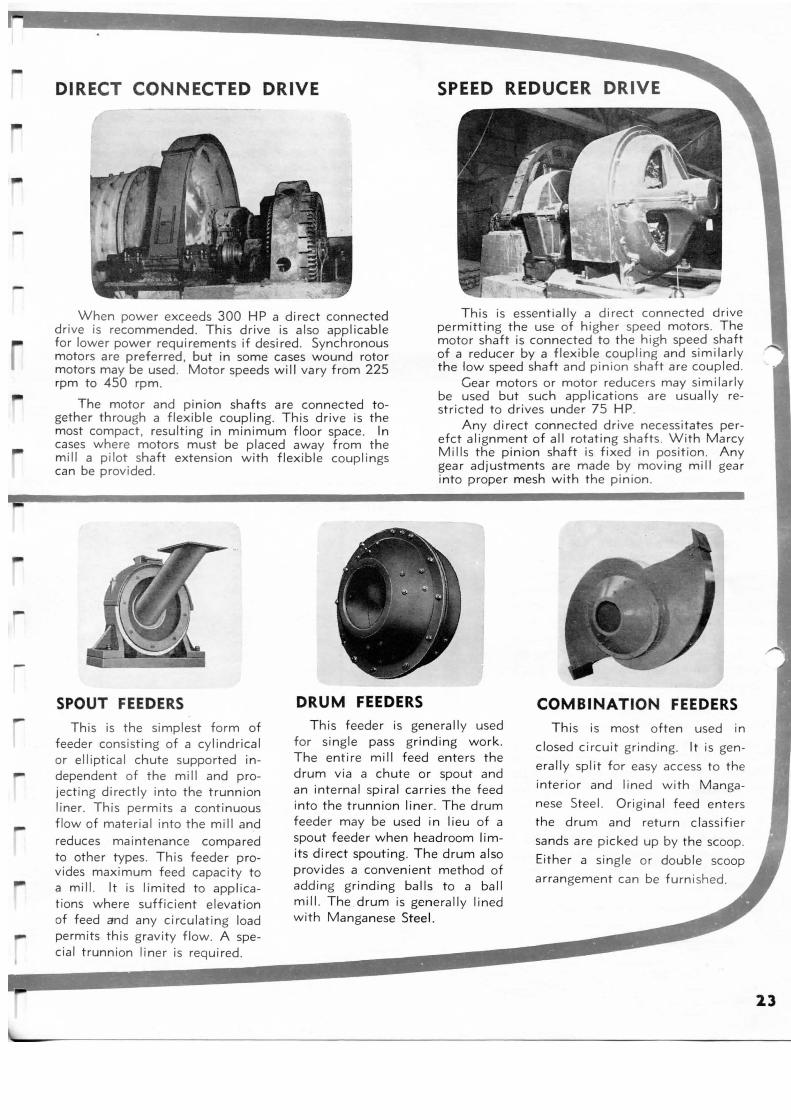
DIRECT CONNECTED DRIVE
When power exceeds 300 HP a direct connected drive is recommended. This drive is also applicable for lower power requirements if desired . Synchronous motors are preferred, but in some cases wound rotor motors may be used. Motor speeds will vary from 225 rpm to 450 rpm.
The motor and pinion shafts are connected together through a flexible coupling. This drive is the most compact, resulting in minimum floor space. In cases where motors must be placed away from the mill a pilot shaft extension with flexible couplings can be provided .
SPOUT FEEDERS DRUM FEEDERS
SPEED REDUCER DRIVE
This is essentially a direct connected drive permitting the use of higher speed motors . The motor shaft is connected to the high speed shaft of a reducer by a flexible coupling and similarly the low speed shaft and pinion shaft are coupled .
Gear motors or motor reducers may similarly be used but such applications are usually restricted to drives under 75 HP.
Any direct connected drive necessitates perefct alignment of all rotating shafts. With Marcy Mills the pinion shaft is fixed in position . Any gear adjustments are made by moving mill gear into proper mesh with the pinion .
COMBINATION FEEDERS
This is the simplest form of feeder consisting of a cylindrical or elliptical chute supported independent of the mill and projecting directly into the trunnion liner. This permits a continuous flow of material into the mill and reduces maintenance compared to other types. This feeder provides maximum feed capacity to a mill. It is limited to applications where sufficient elevation of feed and any circulating load permits this gravity flow . A special trunnion liner is required.
This feeder is genera ll y used for single pass grinding work. The entire mi II feed enters the drum via a chute or spout and an internal spiral carr ies the feed into the trunnion liner. The drum feeder may be used in I ieu of a spout feeder when headroom limits d irect spouting. The drum also provides a convenient method of adding grindi ng balls to a ball mill. The drum is genera lly lined with Manganese Steel.
This is most often used in
closed circuit grinding. It is gen
erally split for easy access to the
interior and lined with Manga
nese Steel. Original feed enters
the drum and return classifier
sands are picked up by the scoop .
Either a single or double scoop
arrangement can be furn ished.
13
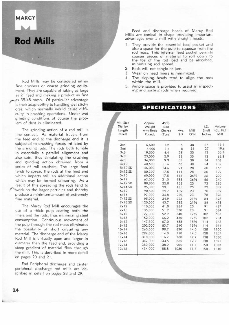
Rod Mills
Rod Mills may be considered either f ine crushers or coarse grinding equipment. They are capable of taking as large as 2" feed and making a product as fine as 35-48 mesh . Of particular advantage is their adaptability to handling wet sticky ores, which normally would cause difficulty in crushing operations. Under wet grinding condi ti'ons of course the problem of dust is eliminated .
The grinding action of a rod mill is line contact. As mater ial travels from the feed end to the discharge end it is subjected to crushing forces inflicted by the grinding rods. The rods both tumble in essentially a parallel alignment and also spin, thus simulating the crushing and grinding action obtained from a ser ies of roll crushers. The large feed tends to spread the rods at the feed end which imparts still an additional action which may be termed scissoring. As a result of this spreading the rods tend to work on the larger particles and thereby produce a minimum amount of extremely f ine material.
The Ma rcy Rod Mill encourages the use of a thick pulp coating both t he liners and the rods, t hus minim izing steel consumption . Continuous movement of the pulp through the rod mass eliminates the possibility of short circuiting any mater ial. The discharge end of the Marcy Rod Mill is virtually open and larger in diameter than the feed end , providi ng a steep gradient of mater ial flow through the mill. This is described in more detail on pages 20 and 21 .
End Per ipheral discharge and center peripheral discharge rod mills are described in detail on pages 28 and 29.
2.4
I
Feed and discharge heads of Marcy Rod Mills are conical in shape providing important advantages over a mi II with straight heads.
1. They provide the essential feed pocket and also a space for the pulp to squeeze from the rod mass . This internal feed pocket permits coarser pieces of material to roll down to the toe of the rod load and be absorbed, minimizing rod spread.
2 . Rods will not tangle or jam. 3 . Wear on head liners is minimized . 4 . The sloping heads tend to align the rods
within the mill. 5 . Ample space is provided to assist in inspect
ing and sorting rods when required .
SPECIFICATIONS
Approx. 45 % Dia . by W eight Rod I. D. Length w /o Rods Charge Ave. Mill Shell (Feet) Pounds (Tons) HP RPM Inches
2x4 6,600 1.2 6 38 27 2x6 7,900 1.7 8 38 27 3x6 19,500 4.4 23 35 43 3x8 23,500 5.9 33 35 43 4x8 34,000 9.3 53 30 54 4x 10 40 ,600 11.6 66 30 54 5x1 0 SD 46,000 14.6 91 28 60 5x12 SD 50,300 17.5 111 28 60 5x10 60,000 17.5 115 26 Y2 66 5x 12 63, 000 21.0 138 26Y2 66 6x12 SD 88,800 25.0 158 25 72 6x 14 SD 95,300 29.1 185 25 72 6x12 90,500 29.7 189 23 78 6x14 97,000 34.8 220 23 78 7x 12 SD 95,000 34.9 225 21 Y2 84 7x15 SD 120,000 43 .7 285 21 Y2 84 7~12 110,000 41.0 264 20 9 1 7x15 135,000 51.2 330 20 91 8x12 122,000 52.9 340 17]12 102 8x15 152,000 66.2 430 17Y2 102 9x12 147,500 67.0 433 15Y2 114 9x 15 202,000 83 .7 540 15 Y2 114
10x14 260,000 99.7 620 14 .0 128 10x 16 297,000 114.0 710 14.0 128 11x14 310,000 116.7 760 12.7 138 11x16 347,000 133.5 865 12.7 138 12x14 380,000 138.9 905 11.7 150 12x16 434,000 158.8 1030 11.7 150
Volume (Cu. Ft .J
Mill
13 .1 19.6 50. 1 66.8
106 132 166 199 200 240 285 332 339 396 398 498 467 584 603 754 763 954
1100 1257 1330 1521 1583 1810
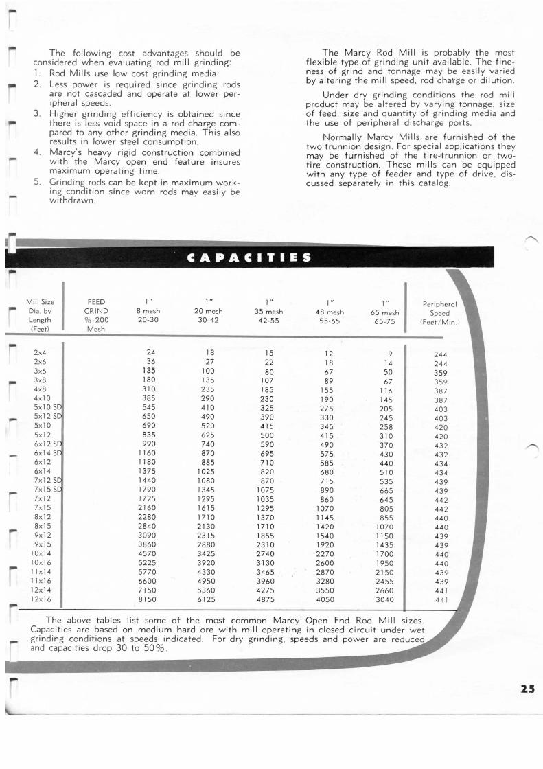
-
--
-
-
-
The following cost advantages should be considered when evaluating rod mill grinding : 1. Rod Mills use low cost grinding media . 2 . Less power is required since grinding rods
are not cascaded and operate at lower peripheral speeds.
3 . Higher grinding efficiency is obtained since there is less void space in a rod charge compared to any other grinding media . This also results in lower steel consumption .
4 . Marcy's heavy rigid construction combined with the Marcy open end feature insures maximum operating time.
5 . Grinding rods can be kept in maximum working condition since worn rods may easily be withdrawn.
Mill Size FEED 1" 1" Dia . by GRIND 8 mesh 20 mesh Length %-200 20-30 30-42 (Feet) Mesh
2x4 24 18 2x6 36 27 3x6 135 100 3x8 180 135 4x8 310 235 4x10 385 290 5x10 545 410 5x12 650 490 5x10 690 52i) 5x12 835 625 6x12 990 740 6x14 1160 870 6x12 1180 885 6x14 1375 1025 7x12 1440 1080 7x15 1790 1345 7x12 1725 1295 7x15 2160 1615 8x12 2280 1710 8x15 2840 2130 9xl2 3090 2315 9x15 3860 2880
10x14 4570 3425 10x16 5225 3920 11x14 5770 4330 11x16 6600 4950 12x14 7150 5360 12x16 8150 6125
1" 35 mesh 42-55
15 22 80
107 185 230 325 390 415 500 590 695 710 820 870
1075 1035 1295 1370 1710 1855 2310 2740 3130 3465 3960 4275 4875
The Marcy Rod Mill is probably the most flexible type of grinding unit available. The fineness of grind and tonnage may be easily varied by altering the mill speed. rod charge or dilution .
Under dry grinding conditions the rod mili product may be altered by varying tonnage . size of feed, size and quantity of grinding med ia and the use of peripheral discharge ports .
Normally Marcy Mills are furnished of the two trunnion design . For special applications they may be furnished of the tire--trunnion or twotire construction . These mills can be equipped with any type of feeder and type of drive . discussed separately in this catalog.
1" 1" Per ipheral 48 mesh 65 mesh Speed 55-65 65-75 (Feet / M in )
12 9 244 18 14 244 67 50 359 89 67 359
155 116 387 190 145 387 275 205 403 330 245 403 345 258 420 415 310 420 490 370 432 575 430 432 585 440 434 680 510 434 715 535 439 890 665 439 860 645 442
1070 805 442 1145 855 440 1420 1070 440 1540 1150 439 1920 1435 439 2270 1700 440 2600 1950 440 2870 2150 439 3280 2455 439 3550 2660 44 1 4050 3040
The above tables list some of the most common Marcy Open End Rod Mill sizes. Capacities are based on medium hard ore with mill operating in closed circuit under wet grinding conditions at speeds indicated . For dry grinding. speeds and power are reduce and capacities drop 30 to 50% .
2 5
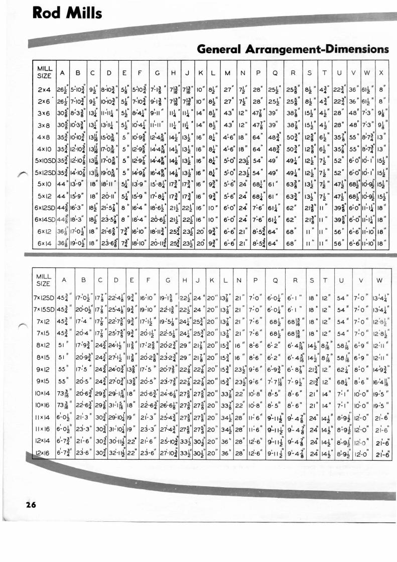
Rod Mills
General Arrangement-Dimensions
MILL SIZE
2x4
2X6
3X6
3x8
4x8
4XI0
A B
sx1osc 35! 1i-1o~ Sx 12SC 35i 14-IO~
It I H
SxiO 44 13-9
6xi2SD 44i 15'-3 "
6xi4SD 44~ 18'-3"
6 XI2
6xl4
MILL SIZE
Ill I , ..
368 11-0 2 I" I , .
368 19-0.z
A B
3 II
7x i2SD 454
7)(15
8xl2
8XI5
9)(12
9xl5
10XI4
10XI6
3 II
454 3 II
454
51
51 II
55
5511
3" 73i6
3 II 73i6
c D
8-'lo~" 4
E F G H j K L
I'' 8.z
I " 9-z 1~1o~"
oO I 311 I ':t It
5~ 7-104 9-18 1'1
8-z 13! 11-'111 "
4 4
13! 13:111 " 4 4
I" 5.z
I " 5-2
tt 1 3 M II
13~ 15-Qi6 5
I I" I ,,
8-44 9-11
. I 5
10·98 I 5 o
12·4i6
nl • 111 " 4 4
nl • Ill • 4 4
• • 14~ 13~
14 01 L" 82.
14n 1u
8-z 16 01 81
1
' 4
13!1. 11-~o~ • 16 16
5 01 12°-9~· I 5"
14·4i6 1410
13!" 2 2 16" 8r
13~ 17~0~ 0
5 II " 1l9I
8
ti I ,5 .. II 13i6 19·0i6 5
I g• 14-4j8 141
01
131. 8 2
II I'' 16 8.4
141" 131 • 16" 81" 8 2 4
17~ • 17~ " 16 " 9f • 18 18~ 11 • sf 1i-9 01
151-8f
I" 18.z
I" 18.z
1811
18"
21~5z' 8" 8
2:3-5!" 8 01
8
c D
I ft I I. 16-4 18-6.z
181-4" 26-5!' 211" 22!" 16 01
2 2 2 I 3 11 31t ,.. II
18-11 4 2s4 232 20
20-111 25:i 23!" 20° 4 4 2
E F G H J
10"
3" 9-4
3" 9-4
K
I II 3'' 21-3 304
23-3" 3oio 31-1
4
M N p Q
27• I ,,
1-z
" 28 I "
25.z • 27 I" 7-z
43" 12 lo 471 . 39'1 8
43. 12 .. 47r 39"
" 64 4~611 18 II
.. 64 4'-s" 18
11
5'-oOI 23~· 54" 49 '1
5~o" 23~ 54 01
49"
51-601 24
1 68l" 61 ol
5~6· 241 s8f 51 •
I tl II
6-6 21
L N
7~6 .. 61r
7~6" 61~ ••
8~51 6401
4
8~5i 54" 4
p Q
R
301
634
62 "
62"
6801
R
21 I II I J'' 1
7-0 6-04 6 -1 I ~~~
6-04
0 " 7- 6 I" 682
I" 682
6°· 1
15 " 68i6
t 511 6 - 4i6
61-4~1
16 I 3 II I 7 II
6-9 4 6 - 88
I I' 8 -5
I 01
8 - 6 I II
8-5 81- 5"
s T u v w X
81 II 3'' 3 .. II I II ,,
2 4.4 224 36 61-z 8
8~ II 4f 22f 3601 61~ II 8
01
15r 4r 28 .. 48" 7~3 .. I" 98
I 11
I 0
28" 48" 7~3 01
15.z 42 I II
98 5"
128 5"
128
I" 12-z
131" z I II
132
I" 6-z I" 6z I II
7-z I II
7-z 71 "
2
I" 7.z
~·· ,, 21 8 II
1 I W II
55 ' 8-7~ 13 4
7 11 II I J W II
358 55 8-74 13
52" 6~0· 10-1" 15r
52 01 6~o" 10- 1" 15r'
47r 68r lo-g£ 15r H tl I H I ll
47~ 68~ 10-~ 152 c:." I .. I 1" II
398 6-0 11-14 18 311 U ,5M I II I 1'' 11
21 8 11 398 6-o 11-14 18 II II
II II II II
II II ss '' s'-6' 11~10" ra"
S T u v w
18 II 1201
54
18 12 54" 7~0 "
18 " 1210 I 01
54 7-0
18" 12 01 II I I I 54 7-0
t'' I 58j6 6-9
0 II
12· 11
r'' ' 58i6 6-9 II Ill
12 624
21 1401 I II
7-t 1d-o11 19-'s "
7~101
9'-11i' I 01
9-41 8
" I" 24 14.z " I I I II
8-9.z 12-0 I u
2 1- 6 I 01
9-llt 91-4i 24" I" 14~ 1
11 I II
8-9~ 12 -0 I 01
2 1-6 I II 3.. I
21-6 304 30-1 I II j I
23·6 304 32-1
20 " 36 " 28 I• 121-6 01
2010
3611
2810
12-6°1
I 01
9-11~ 91-4t 24• l lo
142
24° 14~01
8~-9~·
8~9~·
I II 12-0
I 01
12-0
I 01
21-6 I 01
21-6
2.6

N J-- P- XTX rF. ~ II
~ '-'= l~=:l.IJ.I F-- F=j
.rnl ~
~El '--
D I--A B
..... H -E j
F=
- - -- -
~ p...
y
M . --e:::::: '\ J fl
--: ~H ~ N N ,......
~FJ H F9 ~
--' "--
~ ~
~§ '--
D - I--A B
~~ E
j =
--
if ~
_L
?! p
_ _j__ -
t-::
\ ~ p
1/ s~ =
G F c--L
LJ
r l
1/
9 ~
l/1~a ~F= = r-
G F C L
__, r~ L~
'J:
, I \
V-Belt Drive
The above dimens ions are approximate and for prel iminary use onl y. Ri ght hand mills are shown . Fo r left-hand m ills put drive on opposite side . Dr ive may al so be loca ted at discharge end .
Direct-Connected Drive
The above d imensions are approxima te a nd fo r preli m inary use only . Ri ght-hand m ills are shown. Fo r le ft-hand mil ls put drive on opposite si de . Drive may also be located a t discha rge end .
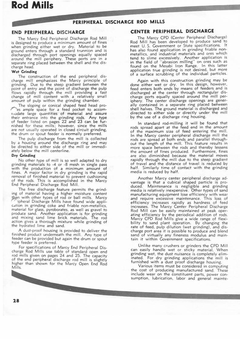
Rod Mills
PERIPHERAL DISCHARGE ROD MILLS
END PERIPHERAL DISCHARGE The Marcy End Peripheral Discharge Rod Mill
is designed to produce a minimum amount of fines when grinding either wet or dry. Material to be ground enters through a standard trunnion and is discharged through port openings equally spaced around the mill periphery. These ports are in a separate ring placed between the shell and the discharge head. Wet Grinding
The construction of the end peripheral discharge mill emphasizes the Marcy principle of grinding. Due to the steep gradient between the point of entry and the point of discharge the pulp flows rapidly through the mill providing a fast change of mill content with a relatively small amount of pulp w ithin the grinding chamber.
The sloping or conical shaped feed head pro-es ample space for a feed pocket to accom
n .odate large quantities of material and assure their entrance into the grinding rods. Any type of feeder listed on pages 22 and 23 can be furnished for these mi lis; however, since the mi lis are not usually operated in closed circuit grinding, the drum or spout feeder is normally preferred .
The pulp discharge from the mill is collected by a housing around the discharge ring and may be directed to either side of the mill or immediately below the mill centerline. Dry Grinding
No other type of mill is so well adapted to dry grinding materials to -4 or -8 mesh in single pass with the production of a minimum amount of fines. A major factor in dry grinding is the rapid removal of finished material to prevent cushioning of the rods. This is accomplislied in the Marcy End Peripheral Discharge Rod Mill.
The free discharge feature permits the grinding of material having a higher moisture content )1;Jan with other types of rod or ball mills. Marcy
·ipheral Discharge Mills have found wide appliCdtion in grinding coke and friable non-metallics , material for glass, pyroborates, as well as gravel to produce sand. Another application is for grinding and mixing sand lime brick materials. The rod action gives a thorough mixture while grinding of the hydrated lime and sand.
A dust-proof housing is prov ided to deliver the finished product underneath the mill. Any type of feeder can be provided but again the drum or spout type feeder is preferred .
For specifications of Marcy End Peripheral Discharge Rod Mills use table of standard open end rod mills given on pages 24 and 25. The capacity of the end peripheral discharge rod mill is slightly h igher than shown for the Marcy Open End Rod Mills.
2.8
CENTER PERIPHERAL DISCHARGE The Marcy CPD (Center Peripheral Discharge)
Rod Mill has been developed to produce sand to meet U. S. Government or State specifications. It has also found application in grinding friable n<;>nmetallics , and industrial materials and ores whtch tend to slime excessively. Another application is in the field of " abrasion milling" on ores such as found on the Mesabi Iron Range. In this latter application true grinding is not desired , but more of a surface scrubb ing of the individual particles.
Again w ith th is construction grinding may be done either wet or dry. In this design , however. feed enters both ends by means of feeders and is discharged at the center through rectangular discharge ports equally spaced around the mill periphery. The center discharge openings are generally contained in a separate ring placed between shell halves. The ground material is discharged and directed to either side or directly under the mill by the use of a discharge ring housing.
In standard rod-milling it will be found that rods spread apart at the feed end in the amount of the maximum size of feed entering the mill. In the Marcy center peripheral discharge mill the rods are spread at both ends and parallel throughout the length of the mill. This feature results in more space between the rods and thereby lessens the amount of fines produced . Furthermore , fines are also diminished because the material moves rapidly through the mill due to the steep gradient of travel and the distance of travel is reduced by half. Similarly time of contact with the grinding media is reduced by half .
Another Marcy center peripheral discharge advantage is that a cubical shaped particle is produced. Maintenance is negligible and grinding media is relatively inexpensive. Other types of sand manufacturing equipment lose efficiency with wear and require excessive maintenance . This loss of efficiency increases rapidly as hardness of feed increases. The Marcy Center Peripheral Discharge Rod Mill can be easily maintained at peak operating efficiency by the periodical addition of rods. Marcy CPD Rod Mills give a wide range of flex ibility to sand plant operation . By changing the rate of feed , pulp dilution (wet grinding), and d ischarge port area it is possible to produce and blend sand of virtually any fineness modulus and maintain it within Government specifications.
Unlike many crushers or grinders the CPD Mill can easily handle wet or sticky material. When grinding wet, the dust nuisance is completely el iminated . For dry grinding applications the mill is furnished with a dust proof discharge hous ing.
Various items must be considered in computing the cost of producing manufactured sand . These include wear on the constituent parts, power consumption, lubrication , labor and general mainte-
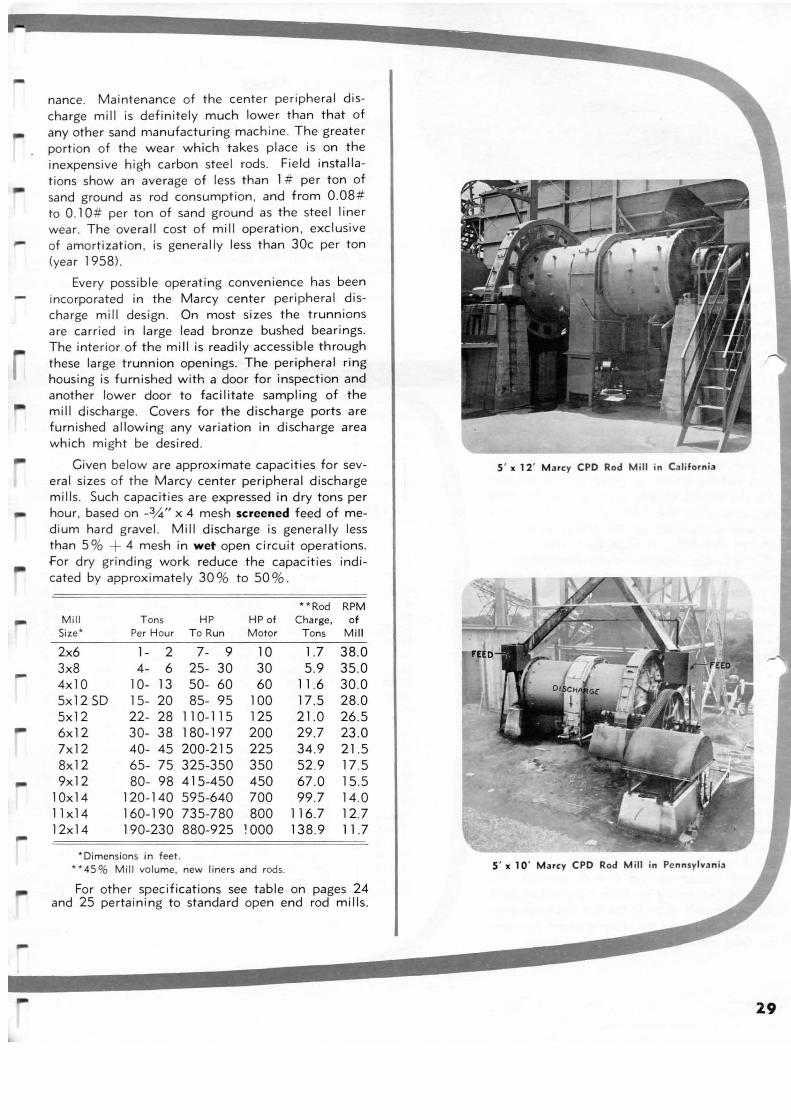
nance. Maintenance of the center peripheral discharge mill is definitely much lower than that of any other sand manufacturing mach ine . The greater portion of the wear which takes place is on the inexpensive high carbon steel rods. Field installations show an average of less than 1 # per ton of sand ground as rod consumption , and from 0.08 # to 0 .1 0# per ton of sand ground as the steel liner wear. The overall cost of mill operation, exclusive
- of amortization . is generally less than 30c per ton (year 1958) .
-
-
Every possible operating convenience has been incorporated in the Marcy center peripheral discharge mill design . On most sizes the trunnions are carried in large lead bronze bushed bearings. The interior of the mill is readily accessible through these large trunnion openings. The peripheral ring housing is furnished with a door for inspection and another lower door to facilitate sampling of the mill discharge. Covers for the discharge ports are furn ished allowing any variation in discharge area which might be desired .
Given below are approximate capacities for several sizes of the Marcy center peripheral discharge mills. Such capacities are expressed in dry tons per hour , based on _3,4" x 4 mesh screened feed of medium hard gravel. Mill discharge is generally less than 5 % + 4 mesh in wet open circuit operations. for dry grinding work reduce the capacities indicated by approximately 30 % to 50 %.
Mill Size *
2x6 3x8 4x10 5x12 SD 5x12 6x12 7x12 8x12 9x12
10x14 11x14 12x14
T ons HP Pe r Hour To Run
1- 2 7- 9 4- 6 25- 30
10- 13 50- 60 15- 20 85- 95 22- 28 1 1 0- 1 1 5 30- 38 180-197 40- 45 200-21 5 65- 75 325-350 80- 98 41 5-450
120-140 595-640 160-190 735-780 190-230 880-925
*Dimensions in feet .
** Rod RPM HP of Charge, of Motor Tons Mill
10 30 60
100 125 200 225 350 450 700 800
1000
1.7 5 .9
11.6 17.5 21.0 29.7 34.9 52.9 67.0 99.7
116.7 138.9
38.0 35.0 30.0 28.0 26.5 23 .0 21.5 17 .5 15 .5 14 .0 12.7 11.7
** 45 % Mill volume, new liners and rods.
For other specifications see table on pages 24 and 25 pertaining to standard open end rod mills.
5 ' x 12' Marcy CPO Rod Mill in Ca liforn ia
5' x 1 0 ' Marcy CPO Rod M ill in Pe nnsylva nia
29
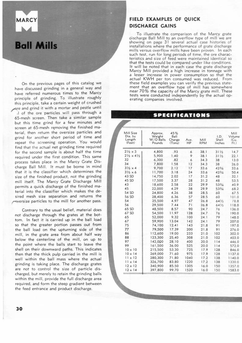
On the previous pages of this catalog we have discussed grinding in a general way and have referred numerous times to the Marcy principle of grinding. To illustrate roughly th is principle, take a certain weight of crushed ~re · and grind it with a mortar and pestle until
,I of the ore particles will pass through a 65-mesh screen. Then take a similar sample but th is time grind for a few minutes and screen at 65-mesh r~moving . the finished mater ial , then return the oversize particles and grind for anot her short period of time and repeat the screening operation. You would find that the actual net grinding time required for the second sample is about half the time required under the first condition . This same process takes place in the Marcy Grate Discharge Ball Mill. It must be borne in mind that it is the classifier which determines the size of the finished product, not the grinding mill itself. The Marcy Grate Discharge Mill permits a quick discharge of the finished material into the classifier which makes the desired mesh size separation and returns the ~versize particles to the mill for another pass.
Contrary to the usual belief, material does not discharge through the grates at the bottom. In fact it is carried up in the ball load so that the greater portion passes out from the ball load on the upturning side of the mill , in the grate area from about half way below the centerline of the mill, on up to the point where the balls start to leave the shell on their downward paths. This indicates then that the thick pulp carried in the mill is well within the ball mass where the actual grinding is taking place. The discharge grates are not to control the size of particle discharged , but merely to retain the grinding balls within the mill , provide the full discharge area required , and form the steep gradient between the feed entrance and product discharge.
30
FIELD EXAMPLES OF QUICK DISCHARGE CAINS
To illustrate the comparison of the Marcy grate ciischarge Ball Mill to an overflow type of mill we a re showing on page 31 several actual case histories of installations where the performance of grate discha rge mills versus overflow mills have been p roven. In each such test, run for long periods of t ime , the ore characteristics and size of feed were ma inta ined identical so that the tests could be compared under like cond it ions. It will be noted that in each case the grate di scharge Marcy Mill provided a high increase in tonnage w ith a lesser increase in power consumption so that the actual KWH per ton consumed was reduced . From these field examples you can verify the prev ious statement that an overflow type of mill has somewhere near 70% the capacity of the Marcy grate mill. These tests were conducted independently by the actual operating companies involved .
.._.,...__.~~.;..:&·
SPECIFICATIONS
Mill Size Approx. 45 % Mill Dia . by Weight Ball I. D. Volume Length W / 0 Balls Charge Ave. Mill Shell (Cu. (Feet) Pounds (Tons) HP RPM Inches Ft.)
2V2 X 3 4 ,800 .93 6 38. 1 31 V2 14.7 2V2 X 4% 5 ,900 1.40 9 38. 1 31 V2 22. 1 32 6,300 .82 6 34 .3 38 13.0 34 7,800 1.58 12 34 .3 38 26.0 3 V2 X 4 9,700 2. 12 17 33.6 423,4 33 .6 3V2 X 6 11 ,700 3 .18 24 33.6 42 3,4 50.4 43 SD 14,750 2.02 17 31.2 48 32. 1 45 SD 17,500 3.37 28 31.2 48 53.5 43 18,600 2.58 22 29.9 533,4 40.9 45 22 ,000 4.29 38 29.9 53 3,4 68 .2 54 SD 24,800 4.26 38 28 .5 60 67 .5 56 SD 28,400 6.36 57 28 .5 60 101. 0 54 25,500 4 .97 47 26.8 64 V2 78.8 56 29 ,500 7.44 71 26.8 64 % 11 8.0 65 SD 48 ,500 8.57 90 24 .7 76 136.0 67 SD 54,500 11 .97 128 24 .7 76 190.0 65 52,000 9 .32 100 24 . 1 79 148.0 67 59,900 13 .04 142 24 . 1 79 207:0 75 74 , 100 12.41 143 21.8 91 197.0 77 79,500 17.39 200 21.8 9 1 276.0 86 112,600 19.00 233 21.0 102 302.0 88 123,300 25.40 308 21.0 102 403 .0 97 142,000 28.10 400 20.0 114 446.0 99 161 ,500 36.00 525 20.0 114 572.0 10 X 10 215 ,500 53.30 725 17.9 128 846.0 10 X 14 269,000 71.60 975 17.9 128 1137.0 11 X 12 280,300 71.80 1040 17.2 138 1140.0 11 X 14 326,700 83 .80 1220 17.2 138 1330.0 12 X 12 340 ,900 85.50 1305 16.0 150 1357.0 12 X 14 397,800 99.70 1520 16.0 150 1583.0
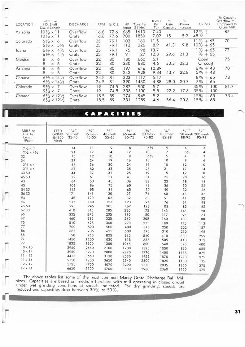
-% Capac ity
Mil l Size KWH % 00 Overflow Mill - LOCATION 1.0. Shell DISCHARGE RPM % C.S. HP Tons Per Per Cain Power GRIND Compared to Dia. x Length Input 24 Hrs. Ton Capacity Increase Grote Mill
Arizona 10 Y2 X 11 Overf low 16.6 77 .6 665 1610 7.40 12 % + 87 10Y2 X 11 Grate 16.6 77 .6 700 1850 7 .02 15 5.2 48 M.
Colorado 6 Y2 X 6 Overflow 25 79.1 102 160 11.5 11 % + 65 70 6 Y2 X SY2 Grate 25 79 .1 112 226 8.9 41.3 9.8 10 % + 65
Idaho 6 Y2 X 4 Y2 Ove rflow 25 79.1 75 98 13 .7 1% + 65 77 6 Y2 X 4Y2 Grate 25 79.1 91 127 12.8 29.6 21.3 1% + 65
Mexico 8 X 6 Overflow 22 80 180 660 5.1 Open 75 8 X 6 Grate 22 80 230 880 4.6 33 .3 22.3 Circcui.t
Arizona 8 X 6 Overflow 22 80 197 646 10.89 6 % + 48 70 8 X 6 Grate 22 80 242 928 9 .34 43 .7 22.8 5 % + 48 - Canada 6 h x14Y2 Overflow 24.5 81 323 1117 5.17 8 % 65 78 6 Y2 x14y2 Grate 24.5 81 390 1430 4.88 28.0 20.7 7 % + 65
Co lorado 9 Y2 X 7 Overflow 19 74.5 287 900 5 .7 35 % + 100 81.7 9 Y2 X 7 Grate 19 74.5 338 1100 5.5 22.2 17 .8 35 % + 100
Canada 6 Y2 x12 Y2 Overflow 18.5 59 274 945 5.2 15 % + 65 73.4 6 Y2 X 12~/2 Grate 18.5 59 331 1289 4 .6 36.4 20.8 15 % + 65
Mill Size FEED 11./.t" 3,1.4" Y2" Y2 " % " %" 1./.t " 1./.t" Dia . by GRIND 20 mesh 35 mesh 48 mesh 65 mesh 80 mesh 100 mesh 1 50 mesh 200 mesh Length %-200 35-40 45-55 55-65 65-75 75-82 82-88 88-95 95-98 (Feet) Mesh
2Y2 X 3 14 11 9 8 6% 5 4 3 2 Y2 x4 Y2 21 17 14 12 10 7 5 Y2 4
32 15 12 10 8 6 Y2 5 4 3 34 29 24 19 16 13 10 8 6
3 Y2 X 4 44 36 30 24 19 15 12 10 3Y2 X 6 63 52 43 35 27 21 17 14
43 so 44 37 31 25 19 15 12 10 45 so 72 61 51 41 31 25 20 16 43 64 53 45 36 28 22 18 14 45 106 86 75 60 46 36 30 22 54 so 115 95 81 65 50 40 32 25 ,- 56 so 171 141 120 97 74 60 48 37 54 145 120 102 82 63 51 4 1 32 56 21 7 180 153 123 94 76 61 48 65 SD 295 245 205 167 128 103 83 65 67 SD 4 10 340 285 230 175 143 116 90 65 335 275 235 190 150 117 95 73 67 460 385 325 260 205 160 130 100 75 510 425 360 290 225 180 145 113 - 77 700 590 500 400 315 250 202 157 86 885 735 625 500 390 310 250 195 88 1150 960 825 660 510 410 330 255 97 1450 1200 1020 815 635 505 410 315 99 1825 1500 1300 1045 800 640 520 400 10 X 10 2960 2450 2100 1700 1325 1050 850 655 10 X 14 3950 3270 2800 2270 1770 1400 1135 875 11 X 12 4425 3660 3130 2530 1955 1570 1270 975 - 11 X 14 5150 4250 3650 2940 2300 1825 1480 1135 12 X 12 5725 4750 4070 3290 2570 2035 1650 1275 12 X 14 6650 5500 4700 3800 2980 2360 1920 1475
- . The abov~ . tables list some of the most common Marcy Grate Discharge Ball Mill s1zes. Capac1t1es are based on medium hard ore with mi ll operating in closed circuit unde r wet grinding conditions at speeds indicated . For dry grinding , speeds are reduced and capacities drop between 30% to SO% .
31
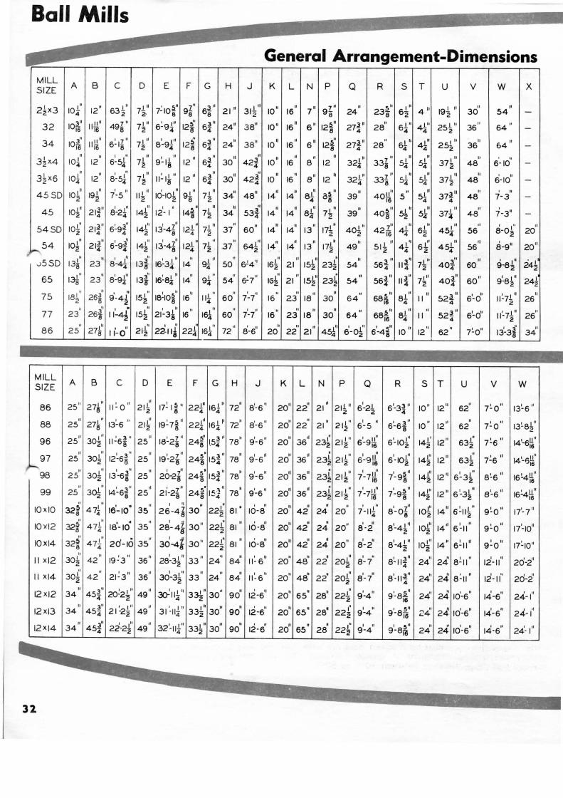
Ball Mills
General Arrangement-Dimensions MILL
A B c D E F G H J K SIZE L N p Q R s T u v w X
2~X3 1o1' 1211 I'' I ~ ' 5 ' 7" 3" 21 II I'' 10
11 II 7 11 7 11 " 5 '' 4 '' 191'' " II 63-z 7-z. 7- IOe 9e 6- 31-z 16 9 - 24 238 30 54 4 8 8 2
3" Ill!." 7" 71 11 6: 9 1" 5' 3" 2411 38" 10 11 1611
6 " 5 " 27}. " " 411' 25~10
36 " 64 " 32 lOiS 16 496 2 4 128 64 128 4 28 4
34 3" II" I 7 11 II' I I" 12~ 3 " II 38" 1o''
II
s " 12~1
27~ " " 61 r" I'' II 64
11 10i6 II i6 6-16 72 8-94 8 64 24 16 8 4 28 4 44 252 36
n II I " " 9~11 " 3 " II 01 10
11 ,,
" 321 " 7 11 " I " II ' ,, 3~X4 10~ 12 6-5l 71 12
11
64 30 421 16 8 12 338 51 s1 372 48 6- 10 2 8 4 4 4
3~X6 IOl • II
81·5f I " II~ 11 " 12
01 6~ 11 3011 II II
a" I" 7'' 51 I" I" " 6-10 II
12 72 8 4 10 16 12 324 338 4 54 372 48
1o1' I" I " Ill 10-101
II Ill Ill 34
11 11 " " ~ II II 40!!
1 I" 37~ 11 II ' II
45SD 192 7-5 112 98 7-z 14 14 81 a8 39 54 48 7-3 2 2 4 16 4
1or I Ill II I •
14~ II 10 "
,, II I II II ~01 5~
Ill I" ol 7-3" 45 8-24 14~ 12- I 71 34 14 14 81 7~ 39 40 8 54 37" 48 2 4
1o1" 3" 6~9~" I" 131-41
ol Ill II II II II II I I' I ll 7'' I ll I" ol 8-ol' " 54SD 2 214 4 142 8 7-z 37 60 14 14 13 172 402 42i6 62 454 56 2 20
1o1" 3" 6~-9~~ , ~~ I II 71 •1 II I" II " II 171'
II I II 6.L' I" II
a-911 20
11 54 214 142 13-4Z 12i 37 642 14 14 13 49 51-z 454 56 2 4 8 2 2 2
131" II
81·4{ " I I ll II I oo
161" " 3 11 3" I I' 4oil " ' I ' 241 ...>5SD 8 23 13i 16-34 14 9i 50 6!4'' 2 21 564 114 72 4 60 9-82 2
65 I" II
13i' I t '' II I '' " 6~7'' 15~1
J." 3" I" 3" 6011 I t il
I~ 23 16-84 14 94 54 21 564 114 72 404 9-82
18111 II I " " . ol " 511 81 1' 3 11 I lo 11 ~71 11 " 75 2 16 114 60 7-7 16 68i6 4 II 524 6-0 2 26
II I " " 511 Ill 3 11 6
1-o" 11 '-71 '
II 77 23 60 7-7 16 68i6 8- II 524 26 4 2
10 II 'I 62 " 7~011 13'-3j'
01 12 8 34
M ILL A B c D E F G H J SIZE K L N p Q R s T u v w
2511
21r II~ 0 " II
17~ I~" 221' Ill " 81· 6 '
1 20'1 II II
21r 61-21 6 1-3~ II 101' 12
11 " 7~0 01
13~6" 86 2 1~ 8 4 164 72 22 21 2 4 62
" 271" 13~ 6 lo 101 ' ~ II II' 161
11 72
11 8'-6 " 20
11 II
" I" I • I ~~~ " 1211 " 7:0 " II' 88 25 8 2 1~ 19-7 8 224 4 22 21 21~ 6-5 6-68 10 62 13~ 82
2511 I '' I 3 II II I 7 11 5' 3 11
7811 9'- 6 11 II ,,
231 I " I 11 11 I I ll
1411
1211 631" 7~6" 141-6!!" 96 302 11-68 25 18-28 248 1.5.4 20 36 2 21 2 6-9iij 6 - 102 2 2 16
" II
12~6~ " II I 7 tl 24~· 3 " • I II II II 23!. I "
II I t'' I" 631' ' " 14'--;!!" 97 25 30~ 25 19-26 154 78 9 -6 20 36 212 6~ 9!! 6-102 142 12
11 7-6
;-98 8 8 2 16 2. 16
II 3o1" 13
1-6i
1 II I Ol 24~· ~II " 9'-6" 20
11 36
11 231: I I' I " o ~II Ill 6 ~3~· 8~6 01 16~4!! " 25 2 8 25 20-2~ 8 154 78 2 212 7-7~ 7-98 142 12
11 16
II
3~ II
14~5"J." 11 21'-21
11 24~· 1"'1" • 9 '-6 '1 20
11 II 23!
I ll 71-7rj' 71-9~ 01 I" I t" 8 ~6 01 16~4!!
11 99 25 6 25 8 8 - 4 78 36 2 212 16 8 142 12
11 6-32 16
" II
1a'-1o " II I II
" . ' II
" II • II
71-111
11 I i' I" 14
11 6 ~ 111 " IOxiO 32i 47~ 35 26 -4~ 30 22~ 81 ' 10-8 20 42 24 20 4 8-o8 102 2 9 ~ 0 01
17'-711
" " I II ,, 28
1- 4 z. 221 " 16-a' 20
10 " . I II I t'l Ill
1411 I " 01 10x12 32i 47~ 18-10 35
8 30 " 2 81 42 24 20'' 8-2 8 -42 102 6 - 11 9~0 1i-1o"
" r" 20'- 10 " 30-4k 221' " o II " • " I II I 111 Ill 6~11 11 I II 10XI4 32~ 474 35 30 " 81 10-8 2010
42 24 20 8-2 8-42 I~ 1411
9-0 1 7~ 10" 6 2 II
" 19~ 3 II
3611 28~31 " 33
11 ,, II 11:6"
II II • 2oi' I " 8~11~
11 II II 8~ 11
II I " 2d-2'1 II x12 30~ 42 2 24 84 20 48 22 2 8-7 4 24 24 12-11
3oi' " 21~3 11 II 30-31" " " " 11 : 6 " 20" 48" 22' 2o1"
I II
8'- 11~" 24' " 8:11 " I ,, I Ol I I Xl4 2 42 36 2 33 24 84
2 8 - 7 4 24 12-11 20-2
" 3" 20~21'' II ~111'' 33-k' 3o'' " ' ,,
2011
6511
28" • 91 II 9 ~8~
11
241
10'-6 II ' " 24-1" 12XI2 34 454 49 90 12-6 22~ -4 24' 14-6 2 4 2 16
II 3" I Ill ,, I I" 331' 30
01 " ' " II 65
11 28' 22£
I " I 5'' " 241
lo'-6" I " 24-1
,, 12XI3 34 454 21 -2-z 49 31-114 2 90 12-6 20 2 9-4 9-8i6 24 14-6
12XI4 " 3" 22-2~· " 32 '-ul" 331" 3001 II
12-6" " " " 22~ I " I .5 11 " 24' o II
14-6 " 24- 1" 34 454 49 4 2 90 20 65 28 9-4 9-8i6 24 10-6
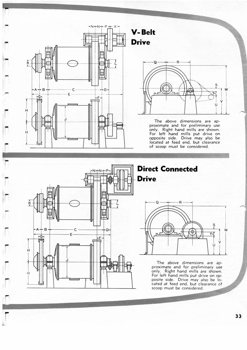
--
H
....
-
'-N 1-N-t-P- -X-;
'-t- I i-A- 4 • B +~+------ C ---- f--l-D
--j-----E - I r-::I-rt-·•
'--t-
V-Belt Drive
The above dimensions are approximate and for preliminary use only. Right hand mills are shown. For left hand mills put drive on opposite side. Drive may also be located at feed end. but clearance of scoop must be considered .
~N+N H:>:dl r. ;-- Direct Connected 1J( 4dbP ~--~
- -t--t-1Th::-t-l:::t-±t-::::!-t-trtW1:Hiffl:t--ti'Rtt-+tr--tl=-IH- Drive t J-111----~IR I~
li
~~ ~ '111---------IIH
-t-1-A-1- B -1-----C -----t~-+-D
=t;r--
The above dimensions are approximate and for preliminary use only. Right hand mills are shown. For left hand mills put drive on opposite side . Drive may a lso be located at feed end . but clearance of scoop must be considered.
I I w
33
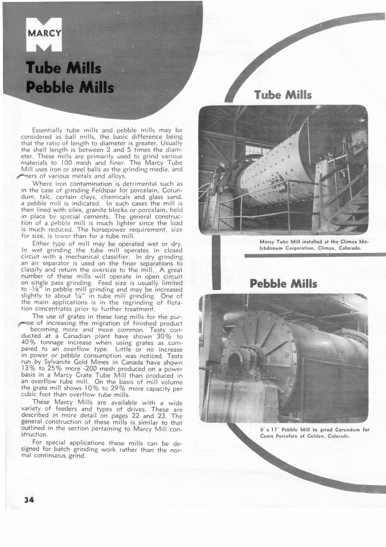
Essentially tube mills and pebble mills may be considered as ball mills, the basic difference being that the ratio of length to diameter is greater. Usually the shell length is between 2 and 5 times the diameter. These mills are primarily used to grind various materials to 100 mesh and finer . The Marcy Tube Mill uses iron or steel balls as the grinding media , and
~ers of various metals and alloys. Where iron contamination is detrimental such as
in the case of grinding Feldspar for porcelain, Corundum, talc , certain clays, chemicals and glass sand, a pebble mill is indicated. In such cases the mill is then lined with silex, granite blocks or porcelain, held in place by special cements. The general construction of a pebble mill is much lighter since the load is much reduced. The horsepower requirement, size for size, is lower than for a tube mill.
Either type of mill may be operated wet or dry. In wet grinding the tube mill operates in closed circuit with a mechanical classifier. In dry grinding an air separator is used on the finer separations to classify and return the oversize to the mill. A great number of these mills will operate in open circuit on single pass grinding. Feed size is usually limited to -Ys" in pebble mill grinding and may be increased slightly to about lh" in tube mill grinding. One of the main applications is in the regrinding of flotation concentrates prior to further treatment.
The use of grates in these long mills for the pur~se of increasing the migration of finished product
becoming more and more common. Tests conducted at a Canadian plant have shown 30% to 40% tonnage increase when using grates as compared to an overflow type. L1ttle or no increase in power or pebble consumption was noticed. Tests run by Sylvanite Gold Mines in Canada have shown 13% to 25% more -200 mesh produced on a power basis in a Marcy Grate Tube Mill than produced in an overflow tube mill. On the basis of mill volume the grate mill shows 10% to 29% more capacity per cubic foot than overflow tube mills .
These Marcy Mills are available with a wide variety of feeders and types of drives. These are described in more detail on pages 22 and 23. The general construction of these mills is similar to that outlined in the section pertaining to Marcy Mill construction.
For special applications these mills can be designed for batch grinding work rather than the normal continuous grind.
34
Marcy Tube Mill installed at the Climax Molybdenum Corporation , Climax , Colorado.
Pebble Mills
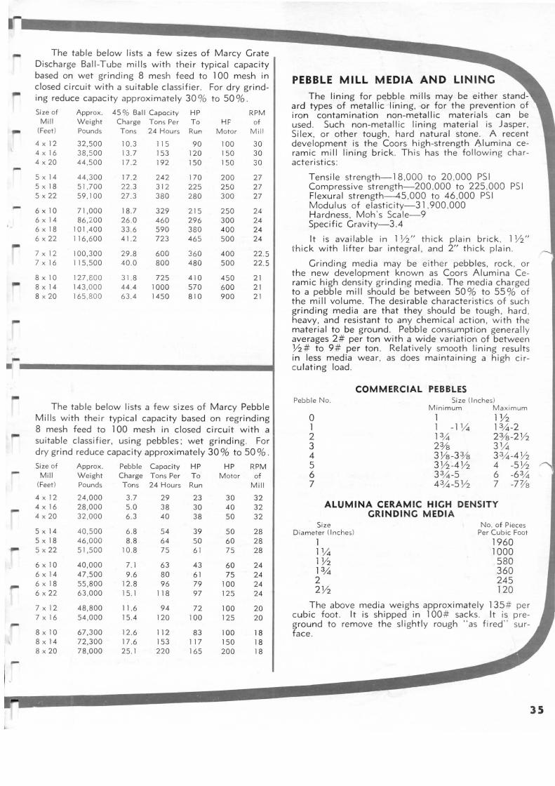
-
-
The table below lists a few sizes of Marcy Grate Discharge Ball-Tube mills with thei r typical capacity based on wet grinding 8 mesh feed to 100 mesh in closed circuit with a suitab le classifier. For dry grinding reduce capacity approximately 30 % to 50 %.
Size of Approx. 45% Ball Capocity HP RPM Mill Weight Charge Tons Per To HF of
(Feet) Pounds Tons 24 Hours Ru n Motor Mi ll
4 X 12 4 X 16 4 X 20
5 X ]4 5 X 18 5 X 22
6 X 10 6 X ]4
6 X 18 6 X 22
7 X 12 7 X 16
8 X 10 8 X ]4 8 X 20
32,500 38,500 44 ,500
44,300 51 .700 59 , 100
71 ,000 86 ,200
101 ,400 116,600
100,300 115,500
127 ,800 143 ,000 165 ,800
10.3 13 .7 17 .2
17 .2 22.3 27.3
18.7 26 .0 33 .6 41.2
29 .8 40 .0
3 1. 8 44.4 63 .4
115 153 192
242 312 380
329 460 590 723
600 800
725 1000 1450
90 120 150
170 225 280
215 296 380 465
360 480
410 570 810
100 150 150
200 250 300
250 300 400 500
400 500
450 600 900
30 30 30
27 27 27
24 24 24 24
22.5 22.5
2 1 21 21
. ... .................................. ~
--
-l
The table below lists a few sizes of Marcy Pebble Mills with their typical capacity based on regrinding 8 mesh feed to 100 mesh in closed circu it with a suitable classifier, using pebbles ; wet grinding. For dry gri nd reduce capacity approximately 30% to 50 %.
Size of Mill
(Feet)
4 X 12 4 X 16 4 X 20
5 X 14 5 X 18 5 X 22
6 X 10 6 X 14 6 X 18 6 X 22
7 X 12 7 X 16
8 X 10 8 X 14 8 X 20
Approx. Weight Pounds
24,000 28 ,000 32,000
40 ,500 46 ,000 51 ,500
40,000 47 ,500 55,800 63 ,000
48,800 54 ,000
67,300 72,300 78,000
Pebble Capocity HP Charge Tons Per To Tons 24 Hours Run
3 .7 5.0 6.3
6 .8 8 .8
10.8
7 .1 9 .6
12.8 15. 1
11.6 15 .4
12.6 17.6 25 .1
29 38 40
54 64 75
63 80 96
118
94 120
112 153 220
23 30 38
39 50 61
43 61 79 97
72 100
83 117 165
HP RPM Motor of
30 40 50
50 60 75
60 75
100 125
100 125
100 150 200
Mill
32 32 32
28 28 28
24 24 24 24
20 20
18 18 18
PEBBLE MILL MEDIA AND LINING The lining for pebble mills may be either stand
ard types of metallic lining, or for the prevent ion of iron contamination non-metallic material s can be used . Such non-metall ic lining material is Jasper. Silex, or other tough , hard natural stone. A recent development is the Coors h igh-strength Alum ina ceramic m ill lining brick. This has the followin g character istics :
Tensile strength-18 ,000 to 20 ,000 PSI Compressive strength-200.000 to 225 .000 PSI Flexural strength--45,000 to 46 ,000 PSI Modulus of elasticity-31 ,900.000 Hardness, Moh 's Scale-9 Specific Gravity-3.4
It is avai lable in 1 Y2" thick plain brick. 1 Y2" thi ck with lifter bar integral, and 2" thick plain .
Grind ing media may be either pebbles, rock , or the new development known as Coors Alumina Ceramic hi gh density grind ing med ia. The media charged to a pebble mill should be between 50 % to 55% of the mill volume. The desirable characteristics of such grind ing media are that they should be tough, hard . heavy, and resistant to any chemical action , with the material to be ground . Pebble consumption generally averages 2 # per ton with a wide variation of between Y2# to 9 # per ton . Relat ively smooth lining results in less media wear, as does maintaining a high circu lating load .
Pebble No.
0 1 2 3 4 5 6 7
COMMERCIAL PEBBLES Size (Inches)
Minimum Maximum 1 1 -11/4 ]3,4 2% 3%-3 % 3Y2-4 Y2 33_4-5 4 3/.t-5 Y2
1V2 13_4-2 2Ys-2 Y2 31/4 3 3/.t-4 Y2 4 -5 Y2 6 -63_4 7 -7Va
ALUMINA CERAMIC HIGH DENSITY GRINDING MEDIA
Size Diameter (Inches)
1 11/4 1Y2 ]3_4 2 2 Y2
No. of Pieces Per Cubic Foot
1960 1000 580 360 245 120
The above media weighs approximately 135# per cubic foot . It is shipped in 1 00 # sacks . It is preground to remove the slightly rough "as fired " surface .
35
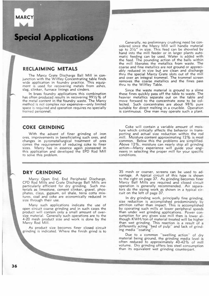
36
RECLAIMING METALS The Marcy Grate Discharge Ball Mill in con
junction w ith the W il fley Concentrating table finds wide application in foundry practice. This equipment is used for recovering metals from ashes, slag, clinker, furnace linings and cinders.
In brass foundry applications this combination has often produced results in recovering 99Y2% of the metal content in the foundry waste. The Marcy method is not complex nor expensive--only limited space is required and operation requires no specially tra ined personnel.
COKE GRINDING With the advent of finer grinding of iron
ores. improvements in beneficiating such ores, and changes in pyrometallurgical treatment of ores comes the requirement of reducing coke to finer sizes. Marcy has in essence again pioneered in th is application and developed ·the EPD Rod Mill to solve this problem.
DRY GRINDING Marcy Open End , End Periphe,al Discharge ,
CPD Rod Mills and Grate Discharge Ball Mills are part icularly efficient fo r dry grinding. Such materials as limestone, cement clinker, gravel , phosphates, clays, gypsum, oil shale , terra cotta mixtures, coal and coke are economically reduced in size through their use.
Many such applications indicate the use of open circuit coarse grinding and in such cases the product will contain only a small amount of oversize material. Generally such operations are to the 4-20 mesh product size and work is done by the Marcy Rod Mill.
As product size becomes finer closed circuit grinding is indicated. Where the finish grind is to
Generally, no preliminary crushing need be considered since the Marcy Mill will handle material up to 3 Y2" in size. This feed can be shoveled by hand into the mill feeder or in larger plants automatic feeding can be used . Water is added with the feed . The pounding action of the balls within the mill liberates the metallics from waste. The coarse and fine metallics are not ground or appreciably reduced in size but are clean and d ischarge thru the special Marcy Grate slots out of the mill and over an integral trommel. The trommel screen removes the coarse metallics and the fines pass thru to the Wilfley Table.
Since the waste material is ground to a slime these fines quickly pass off the table to waste. The heavier metallics separate out on the table and move forward to the concentrate zone to be collected. Such concentrates are about 98% pure suitable for direct melting in a crucible. Operation is continuous. One man may operate such a plant.
Coke will contain a variable amount of moisture which critically affects the behavior in transporting and actual size reduction within the rod mill. Moisture content approximating 12% is most common. Below this the problems are simplified . Above 12%, moisture can nearly stop a II grinding action-Marcy experience will guide your engineers in selecting the proper mill for your specific conditions.
35 mesh or coarser, screens can be used to advantage . A typical circuit of this type is shown to the right on page 37. As grinding becomes finer Marcy Ball Mills are required and closed circuit operation is generally recommended. Air separators do the sizing work as shown in a typ ical circuit on the left of page 37.
In dry grinding work, principally fine grinding, size reduction is accomplished predominately by attrition rather than impact. This is accomplished by operating such mills at lower peripheral speeds than under wet grinding applications. Power consumption for any given size mill then is lower al though KWH/ton of material treated will be higher than wet grinding. This reaction is a result of a differently acting "bed of pulp" and lack of grinding media "coating".
Due to a common "swelling action " of dry material being ground, the grinding media level is often reduced to approximately 40-42 % of mill volume. Dry grinding offers less steel consumption than its equivalent wet grinding counterpart.
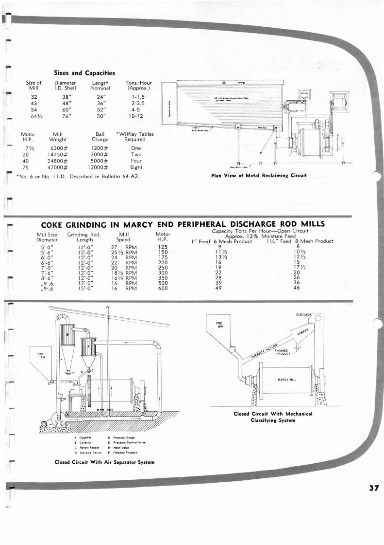
-
I _
....
Sizes and Capacities
Size of Diameter L.ength Tons/ Hour 0 ___ =-Mill I.D. Shell Nominal CApprox.)
32 38" 24" 1-1.5 ---- 190n-o • otno 1 ~ .. , •• ,.,.,.._
43 48" 36" 2-2.5 ---- l oll -• , ., ..
54 60" 52" 4-5 64 Y2 76" 50" 10- 12
~ ........ / Motor M i ll Ball * Wilfley Tables H.P. Weight Charge Required
7Y2 6300# 1200# One 20 14750# 3000# Two 40 24800# 5000 # Four n 75 47000# 12000# Eight
*No. 6 or No. 11 -D. Described in Bulletin 64 -A2 . Plan Vitw of Metal Recla iming Circu it
COKE GRINDING IN MARCY END PERIPHERAL DISCHARGE ROD MILLS M ill Size Diameter
5'-0" 5'-6" 6'-0" 6'-6" 7'-0" 7'-6" 8'-6" ,.9-,6 ,.9-,6
Grinding Rod. Length
12'-0" 12'-0" 12'-0" 12'-0 " 12'-0" 12'-0" 12'-0" 12'-0" 15'-0"
Mill Speed
27 RPM 25 Y2 RPM 24 RPM 22 RPM 20 RPM 1B Y2 RPM 16 Y2 RPM 16 RPM 16 RPM
A Cklndler D Prtuuu Gouo•
8 Col llctOf E PrtiiUtl Control Vo iYt
C Rotorr Fudlr N Nuh Vo lvt
0 Ove,. lu Re!url'l P Flnls htd Product
Closed Circ uit With Air Separator System
Motor H.P.
125 150 175 200 250 300 350 500 600
Capacity Tons Per Hour-Open Circuit Approx. 12 % Moisture Feed
1" Feed 6 Mesh Product 1 V.. " Feed 8 M esh Product 9 8
11 V2 1o Y2 13 Y2 12 Y2 16 15 19 17 Y2 22 20 28 26 39 36 49 46
ORE BIN
Closed Circuit W ith Mechanical Classifyi ng System
37
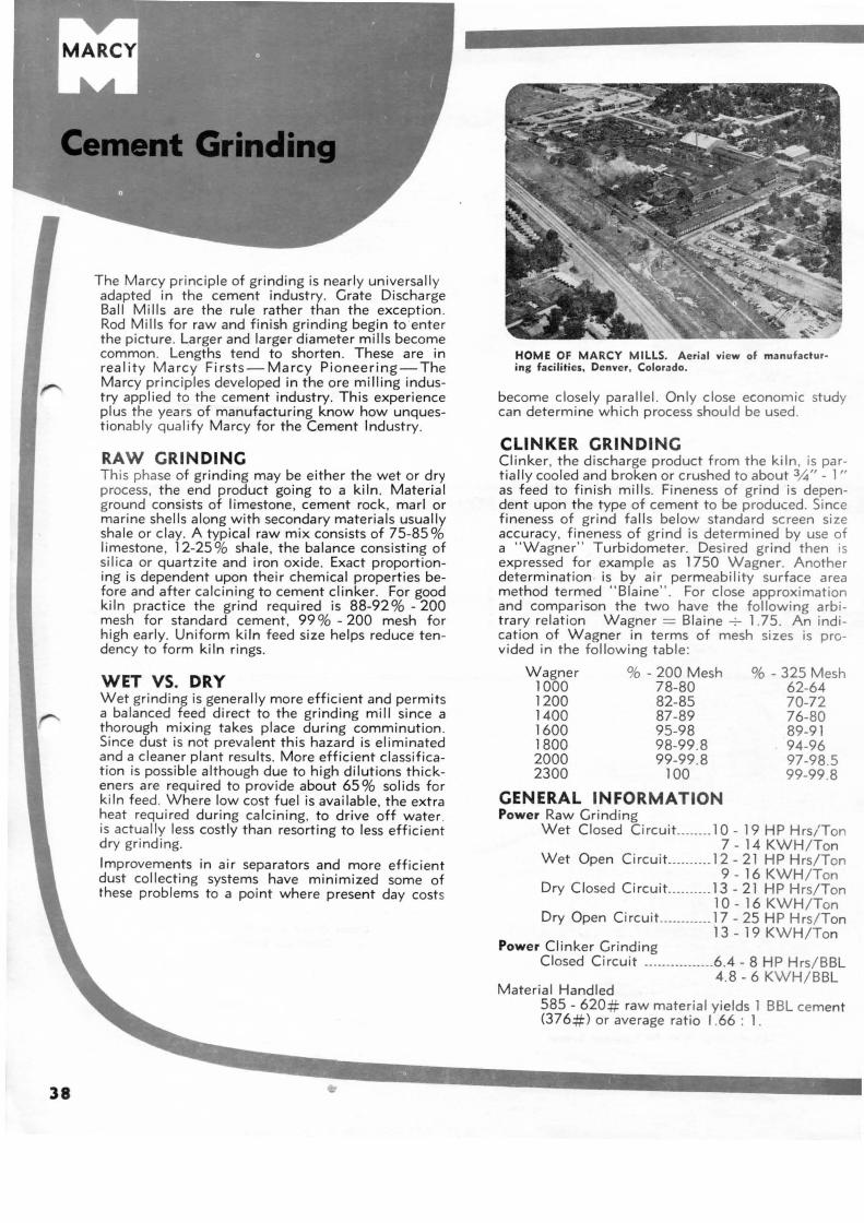
38
The Marcy principle of grinding is nearly universally adapted in the cement industry. Grate Discharge Ball Mills are the rule rather than the exception . Rod Mills for raw and finish grinding begin to enter the picture. Larger and larger diameter mills become common. Lengths tend to shorten . These are in reality Marcy Firsts-Marcy Pioneering-The Marcy principles developed in the ore milling industry applied to the cement industry. This experience plus the years of manufacturing know how unquestionably qualify Marcy for the Cement Industry.
RAW GRINDING This phase of grinding may be either the wet or dry process, the end product going to a kiln . Material ground consists of limestone, cement rock, marl or marine shells along with secondary materials usually shale or clay. A typical raw mix consists of 75-85% limestone , 12-25% shale, the balance consisting of silica or quartzite and iron oxide. Exact proportioning is dependent upon their chemical properties before and after calcining to cement clinker. For good kiln practice the grind required is 88-92%-200 mesh for standard cement, 99% - 200 mesh for high early. Uniform kiln feed size helps reduce tendency to form kiln rings.
WET VS. DRY Wet grinding is generally more efficient and permits a balanced feed direct to the grinding mill since a thorough mixing takes place during comminution. Since dust is not prevalent this hazard is eliminated and a cleaner plant results . More efficient classification is possible although due to high d ilutions thickeners are required to provide about 65% solids for kiln feed . Where low cost fuel is available, the extra heat required during calcining, to drive off water. is actually less costly than resorting to less efficient dry grinding.
Improvements in air separators and more efficient dust collecting systems have minimized some of these problems to a point where present day costs
HOME OF MARCY MILLS. Aerial view of manufactur· ing facilities, Denver, Colorado.
become closely parallel . Only close economic study can determine which process should be used .
CLINKER GRINDING Cl inker, the discharge product from the kiln , is partially cooled and broken or crushed to about 3/.J''- 1" as feed to finish mills . Fineness of grind is dependent upon the type of cement to be produced. Since fineness of grind falls below standard screen size accuracy, fineness of grind is determined by use of a " Wagner" Turbidometer. Desired grind then is expressed for example as 1750 Wagner. Another determination is by a ir permeability surface area method termed " Blaine". For close approximation and comparison the two have the following arbitrary relation Wagner = Blaine -:- 1.75. An indi cation of Wagner in terms of mesh sizes is provided in the followi ng table :
Wagner % - 200 Mesh %-325 Mesh 62-64 70-72 76-80 89-91 94-96 97-98.5 99-99.8
1000 78-80 1200 82-85 1400 87-89 1600 95-98 1800 98-99.8 2000 99-99.8 2300 100
GENERAL INFORMATION Power Raw Grinding
Wet Closed Circuit ... .... . 1 0 - 19 HP Hrs/Ton 7 - 14 KWH /Ton
Wet Open Circui t ... ....... 12- 21 HP Hrs/Ton 9- 16 KWH/Ton
Dry Closed CircuiL ... .... . 13 - 21 HP Hrs/Ton 10 - 16 KWH/Ton
Dry Open Circuit .. ... ..... .. 17- 25 HP Hrs/Ton 13 - 19 KWH/Ton
Power Clinker Grinding Closed Circuit ·- -·· ··------- --6.4 - 8 HP Hrs/BBL
Material Handled 4 .8 - 6 KWH/BBL
585 - 620# raw material yields 1 BBL cement (376#) or average ratio 1.66 : 1.
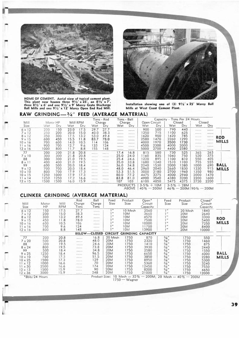
--
HOME OF CEMENT. Aerial view of typical cement plant. This plant now houses three 9 Y:z' x 25', an 8 Y:z ' x 7 ', three 8 'V2 ' x 6' and one 9'V2' x 9 ' Marcy Crate Discharge Ball Mills and one 9 'V2' x 12' Marcy Open End Rod Mill.
Installation showing one of (3) 9 Y:z ' x 25' Marcy Ball Mills at West Coast Cement Plant.
RAW CRINDINC-%" FEED (AVERAGE MATERIAL)
Mill Size
6 X 12 7 X 12 8 X 12 9 X 1S
10 X 16 11 X 16 12 X 16
77 7 X 10
88 8 X 11
99 9 X 12
10 X 10 10 X 1S II X 14 12 X 1S
Tons- Rod Motor HP Mill RPM Charge
Wet Dry Wet Dry Wet Dry 200 1SO 23 .0 17 .S 29 .7 27 .7 2SO 200 20.0 1S .O 40 .0 38 .3 3 SO 300 17 .S 13.2 S3 .0 49.4 600 4SO 1S.S 11.8 83.7 78.0 700 600 14 .0 1 O.S 114 106 900 700 12.7 9 .6 133 124
1000 800 11 .7 8 .8 ISS 148 200 200 21.8 20 .8 --···· ------300 300 21.8 20 .8 ----·- ----- -300 300 21.0 19.S ····-· --- ---400 400 21.0 19.S -----· ---- ·· 600 soo 20.0 18.4 ·----- ------700 700 20 .0 18.4 --···· ---- ·-800 700 17 .9 17.3 ----- - ------
12SO 1000 17 .9 17.3 ------ ----- -12SO 12SO 17.2 16.6 ------ ---- --ISOO 1SOO 16.0 1S.9 -----· ··--··
Tons- Ball I Capacity - Tons Per 24 Hours Charge Open Circuit I Closed !' Closed
Wet Dry Wet Dry Wet Dry Wet Dry
·····- ----- - 900 soo 790 440 ----·· ------------ ----·· 12SO 71S 1100 625 ----- - --- --------- ---- -- 1620 900 1420 78S ...... ----------- - ----- - 2580 1470 2260 1290 ---- -- ------------ ------ 4000 1970 3SOO 1730 --··· · ----- · -- -- -- ------ 4SOO 2300 4000 2000 ...... -- ---· -- ---- ----- - sooo 2700 4400 2380 --·-·· -- -- --17.4 16 .8 81S sao 730 52S 36S 263 25.0 24 .0 1160 83S 1040 7SO S20 375 2S.4 24 .6 1220 89S 1100 810 sso 40S 3S.O 33 .8 1680 1240 1510 1100 7SS sss 36.0 34 .8 2240 1S30 2000 1380 1000 690 48 .0 46 .4 2960 2040 2660 1830 1330 91S 53.3 Sl.S 3000 2180 2700 1960 13SO 980 80.0 77.2 447S 3275 4000 2940 2000 1470 83 .8 81.0 4900 3S40 4380 3200 2200 1600 107 103 6100 48SO S47S 437S 2720 2200 PRODUCTS 1 3-S % + 10M I 3-S % + 28M I
ABOVE 40 %- 200M 46% - 200M 90%- 200M
CLINKER CRINDINC (AVERAGE MATERIAL)
Mill Size
6 X 12 7 X 12 8 X 12 9 X 1S
10 X 16 11 X 16 12 X 16
77 7 X 20
88 8 X 24
99 9 X 2S
10 X 10 10 X 2S 11 X 12 11 X 30 12 X 13 12 X 36
Motor HP 1SO 200 300 4SO 600 700 800
200 soo 300 800 soo
12SO 700
1SOO 1000 2SOO 1SOO 3000
* Bbls/ 24 Hours
Mill RPM 17.S 1S.O 13.2 11.8 1 O.S 9 .6 8 .8
20.8 20 .8 19.S 19.S 18.4 18.4 17 .3 17.3 16.6 16.6 1S.9 1S.9
Rod Cha rge Tons 27 .7 38 .3 49.4 78 .0 106 124 148
Ball I Feed Charge Size Tons ------ 1" ----- - 1" -- -- -- 1" ----- - 1" ----- - 1" ------ 1" ------ 1"
Product Size
10 Mesh 10M 10M 10M 10M 10M 10M
Open* Circuit
Capacity 2S60 3660 4S70 7SOO
10000 11700 13900
BELOW-CLOSED CIRCUIT CRIN DINC CAPACITY
-----· 16 .8 20 Mesh 1750 870 -- ···· 48 .0 20M 1750 2320 ...... 24 .6 20M 1750 1410 ...... 7 3.8 20M 1750 3930 -----· 34 .8 20M 1750 2S80 ····-- 96 .S 20M 1750 66SO ······ S1.S 20M 1750 38SO ------ 129 20M 1750 89SO ---··- 70 20M 1750 S360 ...... 174 20M 1750 12450 ...... 90 20M 175 0 8200 ······ 248 20M 1750 21000
Feed Size
1" 1" 1" 1" 1" 1" I"
3,4" 3,4" 3,4" 3,4" 3,4 " 3,4" 3,4 " 3,4 " 3,4" 3/.j .. 3,4" 3,4"
Product Size
20 Mesh 20M 20M 20M 20M 20M 20M
17SO 1750 1750 17SO 17SO 17SO 17SO 1750 17SO 17SO 17SO 17SO
Product S1ze. 10 Mesh - 32% 200M, 20 Mesh - 40 % 200M 1750 - Wagner
Closed* Circuit
Capacity 1840 2640 3300 S400 72SO 8400
10000
sso 1460 87S
2440 1SSO 4000 2280 S300 3240 7SSO 46SO
12000
I ROD MILLS
I
I BALL MILLS
I
ROD MILLS
I
BALL MILLS
I
39

MARCY DECI MAL EQUI VALENTS OF ONE INCH
.015625 17/ 64 .265625 33/ 64 .515625
.03125 9 / 32 .28125 17/ 32 .531 25
.046875 19/ 64 .296875 35/ 64 .546875
.0625 5 / 16 .3125 9/ 16 .5625
I InfOrmation
1/ 64 l / 32 3/64 l / 16 5 / 64 3 / 32 7 / 64 I / 8 9 / 64 5 / 32
.078125 21 / 64 .328125 37 / 64 .578125
.0937 5 II / 32 .34375 19/ 32 .59375
.109375 23/ 64 .359371 39/ 64 .609375
.125 3 / 8 .375 5 / 8 .625
49/ 64 25 / 32 51 / 64 13/ 16 53/ 64 27/ 32 55/ 64
7/ 8 57/ 64 29/ 32 59/ 64 15/ 16 61 / 64 31 / 32 63/ 64 I
.765625
.78125
.796875
.8125
.828125
.84375
.859375
.875
.890625
.90625
.921875
.9375
.953125
.96875
.984375
DIRECT FACTOR CONVERT ___..
Area 40.46 Acres to Ares 43560 Acres to Sq. Ft. 247.1 Acres to Sq. Kilometers .0015625 Acres to Sq. Miles 160 Acres to Sq. Rods 4840 Acres to Sq. Yards 1076.391 Ares to Sq. Feet .0001 Ares to Sq. Kilometers .1 55 Sq. Centimeters to Sq. ln. .0001 Sq. Centimeters to Sq. Meters 100 Sq. Centimeters to Sq. Millimeters 144 Sq. Feet to Sq. Inches . 09290304 Sq. Feet to Sq. Meters .00000003587 Sq. Feet to Sq. Miles 92903.04 Sq. Feet to Sq. Millimeters .003673094 Sq. Feet to Sq. Rods .111111111 11 Sq. Feet to Sq. Yds. .0064516 Sq. Inches to Sq. Meters 645.16 Sq. Inches to Sq. ~illimeters 1000000 Sq. Inches to Sq. Mils .0000255 Sq. Inches to Sq. Rods .0007716 Sq. lnct1es to Sq. Yards .386108 Sq. Kilometers to Sq. Miles 1000000 Sq. Meters to Sq. Millimeters 1.1959899 Sq. Meters to Sq. Yards 30.25 Sq. Rods to Sq. Yards
Energy .001285 Foot Pounds to British Thermal Un its 1.356 Foot Pounds to Joules .1383 Foot Pounds to Kilogram Meters 4.186 Gram Calories to Joules .000947 Joules to Rritish Thermal Uni ts 107 Joules to Ergs .10198 Joules to Kilogram Meters 3.4126 Watt Hours to British Thermal Unit
11 / 64 3/ 16
13/ 64 7/ 32
15/ 64 1/ 4
.140625 25 / 64 .390625 41 / 64 .640625
.15625 13/ 32 .40625 21 / 32 .65625
.171875 27/ 64 .421875 43/ 64 .671875
.1875 7/ 16 .4375 11 / 16 .6875
.203 125 29/ 64 .453125 45/ 64 .703125
.21875 15/ 32 .46875 23/ 32 .71875
.234375 31 / 64 .484375 47 / 64 .734375
.25 1/2 .5 3 / 4 .75
CONVERSION TABLES REVERSE DIRECT FACTOR FACTOR CONVERT +--- ___..
length .0247157 30.48 Feet to Centimeters .000022956 .3048 Feet to Meters .0040469 2.54 Inches to Centimeters 640 .0254 Inches to Meters .006250 25400 Inches to Microns
.0002066 25.4 Inches to Millimeters .0009290304 25400000 Inches to Millimicrons 10000 1000 Inches to Mils 6.4516 1.6093 Miles to Kilometers 10000 .9144 Yards to Meters .01 .006944444 Power
10.76391 .0000303 Foot Lbs./min. to H.P . 27878400 .0226 Foot Lbs./min. to Watts .000010764 .001818 Foot Lbs./sec. to H.P. 272 .25 1.356 Foot Lbs./ sec. to Watts 9 746 Horse Power to Watts 1550.016
Volume .00155 .000001 28326.14 Cu. Ft. to Cu. Centimeters
39204 1728 Cu. Ft. to Cu. Inches 1296 28.32614 Cu. Ft. to Cu. Decimeters 2.590 .0283261 Cu. Ft. to Cu . Meters .000001 .0370370 Cu. Ft. to Cu. Yards .83612736 28.3173 Cu. Ft. to Liters .0330578 16.387 Cu. Ft. to Cu. Decimeters
.016387 Cu. In to Cu . Meters
.0000214 Cu. ln. to Cu. Yards
.0043290 Cu. ln. to Gallons
.764526 Cu. Yds. to Cu. Meters 3.7851 Gallons to Liters 1.000027 Liters to Cu. Decimeters
778 Weight (Avoirdupois) .7375 1016.05 Long Tons to Kilograms 7.233 28.3495 Ounces to Grams .2388 453.6 Pounds to Grams 1055 .4536 Pounds to Kilograms .0093458 .0004461 Pounds to Long Tons 9.8117 .0005 Pounds to Tons .293 907 .18 Tons to Kilograms
1.
.03281 3.2808 .3937 39.3701 .00003937 .03937 .00000003937 .001 .6214 1.0936
33000 44.25 550 .7375 .001341
.0000353
.0005787
.035314 35.314 27 .035314 .061024 61.0239 46656 231 1.308044 .2642 .999973
.0009842
.035274
.0022046 2.2046 2240 2000 .0011023
THICKENING TANK Flota tion Concentrates 5 to 12 sq. ft . per 24 hr. ton of solids REQUIREMENTS Slimes (Cyanide Plant) 3 to 10 sq . ft . per 24 hr. ton of solids
Easy Settling Ore 3 to 6 sq . ft . per 24 hr. ton of solids Difficult Sett ling Ore 10 to 40 sq . ft . per 24 hr . ton of sol ids
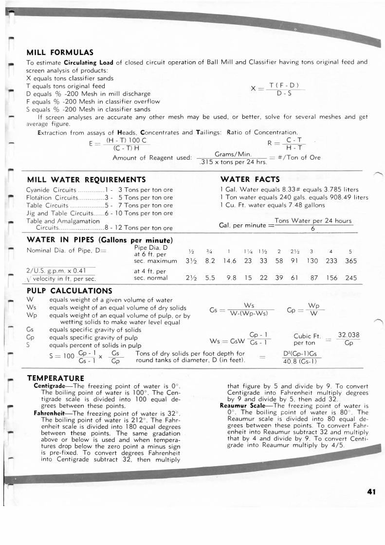
-
-
-
-
MILL FORMULAS To estimate Circu lat ing Load of closed circuit operation of Ball Mill and Classifier having tons original feed and screen analys is of products : X equals tons classifier sands T equals tons original feed D equals % -200 Mesh in mill discharge F equals % -200 Mesh in classif ier overflow S equals % -200 Mesh in classifier sands
X = T(F - D ) D-S-
If screen analyses are accurate any other mesh may be used , or better . solve for several meshes and get average fi gure .
Ext racti on from assays of Heads , Concentrates and Tailings : Ratio of Concentration. E = (H - T ) 1 00 C R = C - T
(C- T) H H - T
Amount of Reagent used :
MILL WATER REQU IREMENTS Cyanide Circuits .............. 1 - 3 Tons per ton ore Flotat ion Circuits ...... .. ...... 3 - 5 Tons per ton ore Tab le Circu its ............. ..... 5 - 7 Tons per ton ore J ig and Table C i rcuits ...... 6 - 1 0 Tons per ton ore Tab le and Amalgamation
Circuits ........ ....... .. ... .. .. 8- 12 Tons per ton ore
W ATER IN PIPES (Gallons per minute) Nominal Dia . of Pipe , D= Pipe Dia . D
at 6 ft . per
- -=-=-=--=C_r.::...a m---=s.::.../_M~i n;. . .,....,..- * / T f 0 = ..,. on o re .315 x tons per 24 hrs.
WATER FACTS Cal . Water equals 8 .33 -tf equals 3 .785 liters Ton water equals 240 gals . equals 908 .49 liters Cu . Ft. water equals 7 .48 gallons
Cal. per minute Tons Water per 24 hours
6
4 5
sec . maximum 3 1/2 8 .2 14 .6 23 33 58 91 130 233 365
2/ U.S. g. p.m. x 0 .41 \ velocity in ft . per sec .
at 4 ft . per sec . normal 2 Y2 5 .5 9 .8 15 22 39 61 87 156 245
PULP CALCULATIONS w equals weight of a given volume of water Ws equals weight of an equal volume of dry solids Cs =
Ws Wp
Wp equals weight of an equal volume of pulp , o r by W-(Wp-Ws) Cp = -w--
wetting solids to make water level equal Gs equals specific gravity of solids Gp equals specific gravity of pulp Cp- 1 Cubic Ft . 32.038
s equals percent of solids in pulp Ws = CsW Cs - 1 per ton Cp
s = 1 00 Cp -_! X Cs Tons of dry sol ids per foot depth for D2 (Cp-1 lCs Cs- 1 cp- rou nd tanks of diameter . D (in feet) . 40 .8 (Cs- 1)
TEMPERATURE Centigrade-The freezing point of water is 0 ° .
The boiling point of water is 100° . The Centigrade scale is divided into 100 equal degrees between these points.
Fah renheit-The freezing point of water is 32° . The boiling point of water is 212° . The Fahrenheit scale is divided into 180 equal degrees between these points. The same gradation above or below is used and when temperatures drop below the zero point a minus sign is pre-fixed . To convert degrees Fahrenheit into Centigrade subtract 32 , then multiply
that figure by 5 and divide by 9 . To convert Cent igrade into Fahrenheit multiply degrees by 9 and divide by 5 . then add 32.
Reaumur Scale-The freezing ,::oint of water is 0 ° . The boiling r:;oint of water is 80 ° . The Reaumur scale is divided into 80 equal degrees between these points . To convert Fahrenheit into Reaumur subtract 32 and multiply that by 4 and divide by 9 . To convert Centi grade into Reaumur multiply by 4/5.
41
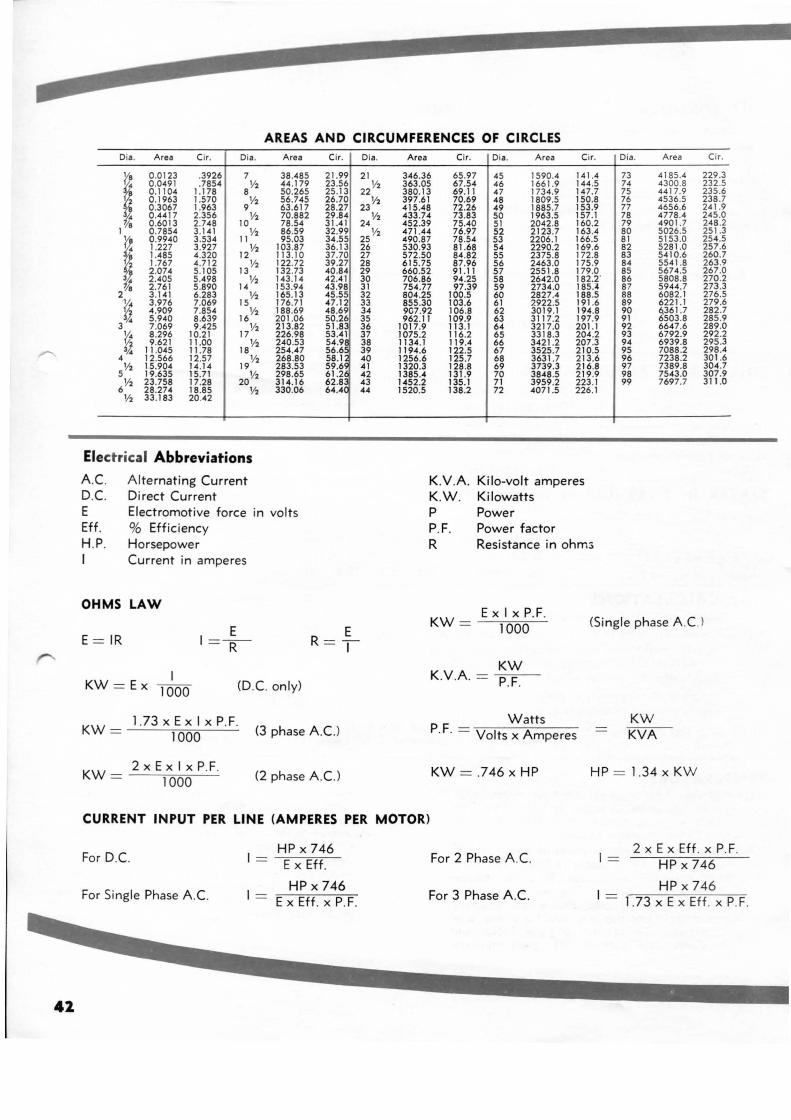
AREAS AND CIRCUMFERENCES OF CIRCLES Dia . Area Cir. Dia . Area
I 0 .0123 .3926 7 38.485 0 .0491 .7854 V2 44 .179 0 .11 04 1.178 8 50.265 0 .1 963 1.570
9V2 56.745
0 .3067 1.963 63.617 0 .4417 2.356 V2 70.882
/ 8 0 .60 13 2 .748 10 78.54 0.7854 3.141 V2 86.59
~ 0 .9940 3 .534 11 95.03 1.227 3.927 12V2 103.87 1.485 4.320 113. 10
~ 1.767 4.712 V2 122.72 2 .074 5.105 13 132.73 2.405 5.498 V2 143.14 2 .761 5 .890 14 153.94
2 3.141 6.283 V2 165.13
~· 3 .976 7.069 15 176.71
~ 4.909 7.854 Y2 188.69 5 .940 8 .639 16 201 .06
3 7 .069 9 .425 V2 213.82
~· 8 .296 10.21 17 226.98
~ 9 .621 11 .00 V2 240.53 11 .045 11.78 18 254.47
4 12.566 12.57 Y2 268.80
5V2 15.904 14.14 19 283.53
19.635 15.71 V2 298.65 Y2 23.758 17.28 20 314.16
6 28.274 18.85 V2 330.06 V2 33.183 20.42
Electrical Abbreviations
Alternating Current A. C. D.C. E Eff. H.P. I
Direct Current Electromotive force in volts % Effic iency Horsepower Current in amperes
OHMS LAW
E = IR
I KW =Ex 1000
E I =~
(D .C. only)
Cir.
21.99 23.56 25 .13 26.70 28.27 29.84 31.41 32.99 34.55 36.13 37.70 39.27 40.84 42.41 43 .98 45.55 47.12 48 .69 50.26 51.8 53.41 54.9 56.6 58.1 59.6 61.2
~Uc
E R =-1
KW = 1.73 X EX I X P.F. 1000 (3 phase A.C. )
2xExlxP.F. KW = 1000 (2 phase A.C.)
Dla.
21
22 V2
23 Y2
24 V2
25 V2
26 27 28 29 30 31 32 33 34 35 36 37 38 39 40 41 42 43 44
Area Cir.
346.36 65.97 363.05 67.54 380.13 69. 11 397.61 70.69 415.48 72.26 433.74 73.83 452.39 75.40 471.44 76.97 490.87 78 .54 530.93 81 .68 572.50 84.82 615.75 87.96 660.52 91.11 706.86 94.25 754.77 97.39 804.25 100.5 855.30 103.6 9C7.92 106.8 962.11 109.9
1017.9 113.1 1015.2 116.2 1134.1 119.4 1194.6 122.5 1256.6 125.7 1320.3 128.8 1385.4 I 31.9 1452.2 135.1 1520.5 138 .2
K.V.A. K.W . p P.F. R
Dia. Area Cir.
45 1590.4 141.4 46 1661 .9 144 .5 47 1734.9 147.7 48 1809.5 150.8 49 1885.7 153.9 50 1963.5 157 .1 51 2042.8 160.2 52 2123.7 163.4 53 2206.1 166.5 54 2290.2 169.6 55 2375 .8 172.8 56 2463.0 175.9 57 2551.8 179.0 58 2642.0 182.2' 59 2734.0 185.-4 60 2827.4 188 .5 61 2922.5 191.6 62 3019.1 194.8 63 3117.2 197.9 64 3217 .0 201.1 65 3318.3 204.2 66 3421.2 207 .3 67 3525.7 210.5 68 3631.7 213.6 69 3739.3 216.8 70 3848.5 219.9 71 3959.2 223.1 72 4071 .5 226.1
Kilo-volt amperes Kilowatts Power Power factor Resistance in ohm:;
Dia. Area Cir.
73 4 185.4 229.3 74 4300.8 232.5 75 44 17.9 235.6 76 4536.5 238 .7 77 4656.6 241.9 78 4778.4 245.0 79 4901 .7 248 .2 80 5026.5 25 1.3 81 5153 .0 254 .5 82 5281.0 257 .6 83 5410.6 260.7 84 5541 .8 263.9 85 5674.5 267.0 86 5808.8 270.2 87 5944 .7 273.3 88 6082.1 276.5 89 6221 .1 279.6 90 ~361.7 282.7 91 6503.8 285.9 92 6647.6 289.0 93 6792.9 292.2 94 6939.8 295.3 95 7088 .2 298.4 96 7238.2 301 .6 97 7389.8 304.7 98 7543.0 307.9 99 7697.7 311.0
KW = EX I X P.F. 1000 (Si ngle phase A.C. l
KW K.V .A. = P.F.
p F = Watts · · Volts x Amperes
KW = .746 X HP
KW KVA
HP = 1.34 X KW
CURRENT INPUT PER LINE (AMPERES PER MOTOR)
For D.C. I = HP X 746
For 2 Phase A.C. I = 2 X EX Eff . X P.F.
EX Eff. HP X 746
For Single Phase A.C. I = HP X 746
For 3 Phase A.C. I- HP X 746
EX Eff. X P.F. - 1.73 X EX Eff . X P.F.
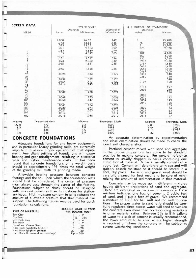
-
r: r
SCREEN DATA
MESH
3 4 5 6 8
10 12 14 16 20 25 28 35 48 50 60 65 70 80
100 120 150 200 270 325 400
Microns Theoretical Mesh 22 .0 673 18.5 800 13. 1 1130 11.0 1346
TYLE R SCALE Openings
Inches Mi llimeters
1. 050 26 .67 .7 42 18 .85 .525 13 .33 .371 9 .423 .263 6 .680 . 185 4 .699
. 131 3.327 093 2 .362
.065 1.651
.046 1. 168
.0328 .833
.0232 .589
.0164 .417
.0116 .295
.0082 .208
.0069 . 175
.0058 . 147
.0041 . 104
.0029 .074
.0021 .053
.0014
.0015 .038
Microns 9 .3 7.8 5 .5 3 .9
CONCRETE FOUNDATIONS Adequate foundations for any heavy equipment,
and in particular Marcy grinding mills , are extremely important to assure proper operation of that equipment. Any slight settling of foundations will cause bearing and gear misalignment, resulting in excessive wear and higher maintenance costs. It has been found that concrete foundations on a weight basis should be approximately 1 Y2 times the total weight of the grinding mill with its grinding med ia.
Allowable bearing pressure between concrete footings and the soi I upon which the foundation rests should first be considered . The center of pressure must al~ays pas~ through the center of the footing . F~undat1ons . subject to shock should be designed w1th less un 1t pressures than foundat ions for stationary loads. High moisture content in soils reduces the amount of allowa ble pressure that that material can support. The fo llow ing f igures may be used for quick foundation calculat ions :
TYPE OF MATERIAL Soft Clay Dry Sand Dry thick Clay Soft Rock Gravel and Coarse Sand Hard Rock (partia lly broken) Hard Rock (slightly broken) Hard Rock (i n na tural surroundings)
BEARING LOAD IN TONS PER SQUARE FOOT
1 - 2 1Y:z- 3 Y2 3 - 6 5 - 9 7 - 10
15 - 20 20 - 30 Up to 200
U. S. BUREAU OF STA NDARDS Dia mete r of Openings Wire- Inches Inches Microns
.1 49 1 25 ,400
. 135 .75 19 ,100
.1 05 .5 12,700
.092 .375 9 ,520
.070
.065 . 187 4,760 .157 4 ,000
.036 . 13 2 3 ,360
.032 .0937 2 ,380
.035 .07 87 1,680 .0661 1,4 10
.025 .0555 1, 190 .0469 1,000
.0 172 .0331 840 .0280 710
.0125 590
.0122 .0197 420
.0092 .0 117 297 .0098 250
.0072 210 .0083
.0056 .0070 177
.0042 .0059 149 .0049 125
.0026 105
.0021 .0029 74
.0016 .0021 53
.0014 .0017 44
.0010 .0015 37
Theoret ical Mesh Microns Theoretical Mesh 1590 2. 8 5 ,280 1898 1.64 9 ,030 2690 1.16 12 ,7 80 3800 .82 18 ,000
An accurate determination by experimentation and close examination should be made to check the exact soi I characteristics.
Portland cement mixed with sand and aggregate in the proper proportions has come to be standard practice in making concrete . For general reference cem.ent is usually ~hipped in sacks conta ining one cub~c foot of matenal. A barred usually consists of 4 cu?lc feet . Cement will deteriorate with age and will qu1ckly absorb moisture so it should be stored in a cool , dry place. The sand and gravel used should be carefully cleaned for best results to be sure of minimizing the amount of sedimentation in that material.
Concrete may be made up in different mixtures having different proportions of sand and aggregate . These are expressed in parts- for example a 1 :2 :4 mixture indicates one bag of cement, 2 cubic feet of sand , and 4 cubic feet of gravel . We recommend a mixture of 1:2 :3 for ball mill and rod m ill foundations . The proper water to sand ratio should be carefully regulated since excess water wi II tend to weaken the concrete even more than corresponding variat ions in other material ratios. Between S Y2 to 8 Y2 gallons of water to a sack of cement is usually recommended , !he lov.:-er amount to be used where higher strength IS requ1red or where the concrete will be subject to severe weathering condit ions.
4
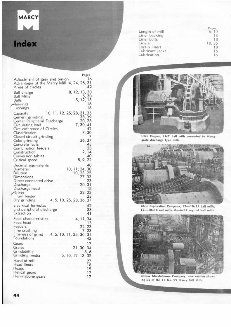
Pages
Adjustment of gear and p inion 16 Advantages of the Marcy M i ll 4 , 24, 25 , 31 Areas of circl es 42
Ball charge 8, 12, 13 , 30 Ball Mills 5 , 30 Balls 5 , 12, 13
,aearings 16 ushings 16
Capacity 10 , 11 , 12, 25 , 28, 31, 35 Cement grinding 38, 39 Center Peripheral Discha rge 20, 28 Circulat ing load 7 , 30, 41 Circumference of Ci rc les 42 Classificat ion 7 , 30 Closed circuit grinding 7 Coke grinding 36, 37 Concrete facts 43 Combination feeders 23 Construction 2, 14 Conversion tables 40 Critical speed 8, 9, 22
Decimal equivalents 40 Diameter 1 0 , 11 ; 24, 30 Dilution 10, 23 , 25 Dimensions 27 , 33 Direct connected dri ve 23 Discharge 20, 3 1 Discharge head 15
rrives 22, 23 rum feeder 23
Dry grinding 4 , 5, 1 0, 25, 28 , 36 , 37
Electrical fo rmulas End peripheral discharge Extraction
42 28 41
Feed characteristics Feed head Feeders Fine crushing Fineness of grind Foundations
Gears Grates Grindabilit Grinding media
Hand of mill Head liners Heads Helical gears Herringbone gears
44
4, 11' 34 15
22, 23 7 , 23
4 , 5, 1 0 , 11 ' 25 , 30 , 34 43
17 21, 30, 34
3 , 6 5, 10, 12, 13, 35
27 18 15 17 17
Length of mill Liner backing Liner bolts Liners Lorain liners Lubricant jacks Lubrication
Pages 6 . 10
18 18
18. 35 18 16 16
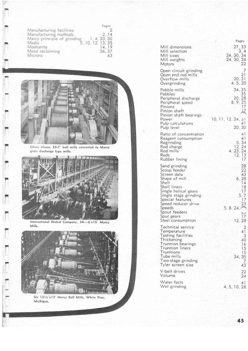
Pages
Manufacturing facilities 2 Manufacturing methods 2 , 14 Marcy principle of grinding 1, 4, 20, 30 Media 5 , 10, 12, 13 , 35 Meehanite 14 , 19 Metal reclaiming 3 6 , 37 Microns 43
,..
Mill dimensions Mill selection Mill sizes Mill weights Motors
Open circuit grinding Open end rod mills Overflow mills Overgrinding
Pebble mills Pebbles Peripheral discharge Per ipheral speed Pinions Pinion shaft Pinion shaft bearings Power Pulp calculat ions Pulp level
Ratio of concentration Reagent consumption Regrinding Rod charge Rod mills Rods Rubber lining
Sand grinding Scoop feeder Screen data Shape of mill Shell Shell liners Single hel ical gears Single stage grind ing Special features Speed reducer drive Speeds Spout feeders Spur gears Steel consumption
Technical serv ice Temperature Testing facilities Thickening Trunnion bearings Trunnion liners Trunnions Tube mills Two-stage grinding Tyler screen s ize
V-belt drives Volume
Water facts Wet grinding
Pages
27 , 33 3 . 4
24 , 30, 34 24 , 30, 34
22
7 21
20 , 31 4 , 5 , 20
34 , 35 35
20 . 28 8, 9 . 25
17 ):{
10. 11 . 12 , 24 , J I 41
20 , 30
41 41
5 , 34 12. 24
4 , 23 . 24 12, 13
17
28 22 43
6, 28 14 18 17
5, 7 17 23
5. 8. 24 .
17 12. 28
2 41
3 40 16 15 15
34 , 35 7
43
22 24
41 4 . 5, 10 , 28
45
JHE ORE & CHEMICAL CORPORATION 235 East 42nd Street New York, N.Y. 10017
MINE AND SMELTER SUPPLY CO. MANUFACTURING DIVISION
Executive Offices and Main Plant:
3800 Race St., P.O. Box 9041 Denver 16, Colorado
Branch Offices: Albuquerque, New Mexico; 701 Haines Ave, N.W. El Paso, Texas; 1515 Eleventh Ave. New York City, N.Y.; 122 East 42nd Street Salt Lake City, Utah; 375 West 21st Street San Jose, Calif.; 1636 Nord Lane Tucson, Ariz. ; P.O. Box 849
Main Export Office: Denver, Colorado, U.S.A.
Cable Address:
MINTERPLY
Please write our Denver, Colorado office for names and addresses of our fore ign licensed manufacturers and sales agents.
Prin ted in U.S.A.