marchagee oil mallee study : drill completion and
TRANSCRIPT
Research Library Research Library
Resource management technical reports Natural resources research
1-1-2009
Marchagee oil mallee study : drill completion and preliminary Marchagee oil mallee study : drill completion and preliminary
hydrogeological report hydrogeological report
D L. Bennett
Adrian Goodreid
Follow this and additional works at: https://researchlibrary.agric.wa.gov.au/rmtr
Part of the Agriculture Commons, Environmental Indicators and Impact Assessment Commons,
Environmental Monitoring Commons, Fresh Water Studies Commons, Hydrology Commons, Natural
Resources Management and Policy Commons, Soil Science Commons, and the Water Resource
Management Commons
Recommended Citation Recommended Citation Bennett, D L, and Goodreid, A. (2009), Marchagee oil mallee study : drill completion and preliminary
hydrogeological report. Department of Primary Industries and Regional Development, Western Australia, Perth. Report 340.
This report is brought to you for free and open access by the Natural resources research at Research Library. It has been accepted for inclusion in Resource management technical reports by an authorized administrator of Research Library. For more information, please contact [email protected].

Marchagee oil mallee study
Drill completion and preliminary hydrogeological
report
RESOURCE MANAGEMENT TECHNICAL REPORT 340

ISSN 1039-7205
Resource Management Technical Report 340
Marchagee oil mallee study Drill completion and preliminary hydrogeological
report Don Bennett and Adrian Goodreid
June 2009
Disclaimer The Chief Executive Officer of the Department of Agriculture and Food and the State of Western Australia accept no liability whatsoever by reason of negligence or otherwise arising from the use or release of this information or any part of it.
Copyright © Western Australian Agriculture Authority, 2009
Copies of this document are available in alternative formats upon request.
3 Baron-Hay Court, South Perth WA 6151 Tel: (08) 9368 3333 Email: [email protected] www.agric.wa.gov.au


Marchagee Oil Mallee Study
i
Contents Page
Acknowledgments ......................................................................................................... iii Summary ........................................................................................................................ v
1. Introduction .......................................................................................................... 1 1.1 The study site ................................................................................................ 1 1.2 Catchment setting ......................................................................................... 3 1.3 Hydrogeological setting ................................................................................. 4 1.4 Climate .......................................................................................................... 4
2. Hydrogeological investigation ............................................................................ 6 2.1 Previous investigations ................................................................................. 6 2.2 Drilling methods ............................................................................................ 7 2.3 Drill sample analyses methods ..................................................................... 7 2.4 Groundwater monitoring and sample analyses methods .............................. 8 2.5 Hydraulic conductivity measurements ........................................................... 8 2.6 Surveying ...................................................................................................... 8 2.7 Geophysics ................................................................................................... 8
3. Results and discussion ....................................................................................... 9 3.1 Profile descriptions ........................................................................................ 9 3.2 Groundwater levels ....................................................................................... 12 3.3 Groundwater quality ...................................................................................... 14 3.4 Geophysics ................................................................................................... 14 3.5 Flowtube modelling ....................................................................................... 22
4. Conclusions .......................................................................................................... 27
5. References ............................................................................................................ 28
6. Appendixes ........................................................................................................... 30 6.1 Field drill logs ................................................................................................ 30 6.2 EC1:5, EM39 and Gamma profiles ................................................................. 42 6.3 Bulk soil sample analyses ............................................................................. 45 6.4 Comparison of EC1:5 and EM39 .................................................................... 48

June 2009
ii

Marchagee Oil Mallee Study
iii
Acknowledgments This project could not proceed without the support and enthusiasm of John and Robyn Stacy and family, on whose property this research work was undertaken. This project is a joint project between the Rural Industries Research and Development Corporation, who provided most of the funding for setting up this study site, the Department of Agriculture and Food, Department of Environment and Conservation and the Oil Mallee Company. Thanks to John Bartle, Dan Huxtable, Gabby Pracilio, Jodie Watts, Marie Strelein, Lindsay Bourke and Ned Stephenson for their help with field data collection and management.
Thanks also to Grant Stainer and Angela Stuart-Street for their constructive criticism and Janet Blagg for final editing.

June 2009
iv

Marchagee Oil Mallee Study
v
Summary Oil mallees are being planted on WA wheatbelt farms with the expectation that they will reduce land salination by lowering watertables and provide income in the future from eucalyptus oil distillation, power generation, activated carbon production and carbon sequestration.
This report details the drill completion and hydrological interpretation of a site at Marchagee (near Coorow) that had been provided with instruments in order to study the effect on groundwater conditions and land salinity of an extensive planting (in 2000) of oil mallees.
A hill slope planted with oil mallees in two-row belts spaced at 120 m intervals was selected for intensive hydrogeological investigation and instrumentation for ongoing groundwater monitoring. This report details the results of a deep drilling program, soil and water analysis, ground-based geophysical mapping comprising EM38, EM31 and radiometrics, and associated analysis and groundwater modelling.
The study site is located within a small sub-catchment that drains directly into the main flow line of the Buntine Marchagee catchment, a large (approximately 181 km2) catchment. The braided, broad drainage line consists of a series of primary salt lakes that rarely have surface water flow connection. Soils at the site are predominantly the typical non-acidic yellow sandplain soils of the northern wheatbelt, formed from remnants of the Tertiary aeolian sandsheet and represent types that are the focus of the oil mallee industry in this area.
Preliminary results indicate that:
• The site is almost at equilibrium in terms of extent of salinity, however groundwater levels in the upper slopes would have continued to rise without an altered water use regime or a persistent reduction in long-term average rainfall.
• The existing oil mallee configuration needs to prevent all recharge and use more than an additional 100 mm of groundwater from a 20 m wide strip beneath the belt system to reduce groundwater levels significantly under the alley system.
• More than 200 mm of groundwater use is required to almost eliminate groundwater under most of the belt system.
• While substantial groundwater use may be possible given the moderate salinities at the watertable, it is unlikely for most of the study area because of the prevalent silcrete layer which acts as a physical barrier to the roots reaching the watertable.
• Because of the combination of low groundwater gradient, a basement high that severely reduces the aquifer thickness, and the large stagnant groundwater system associated with the main drainage line below, the capacity of the groundwater system to drain in the area below the planting is greatly restricted. For this reason watertables and land salinity below the planting will remain unaffected even under the most optimistic water use scenario.
• Permanent perched systems could offer an additional small water source for the mallees in similar situations. However, they are likely to be of small capacity, topped up by annual recharge, and located in pockets where the silcrete is less leaky or in lower slope accumulation areas.

June 2009
vi
Marchagee Oil Mallee Study
1
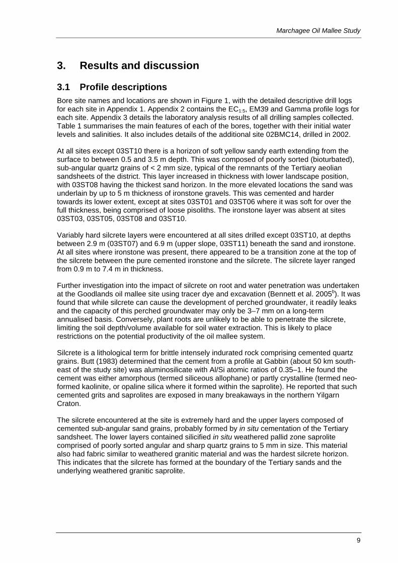
1. Introduction Oil mallees are being planted on wheatbelt farms with the expectation that they will reduce land salination by lowering watertables as well as provide income from combinations of eucalyptus oil distillation, power generation, activated carbon production and carbon sequestration in the future.
The Department of Agriculture and Food, Western Australia (DAFWA) commenced a groundwater study in May 2003 on a hill slope containing a series of oil mallee alleys on Calecono farm, Marchagee, belonging to John and Robin Stacy. This is part of a larger RIRDC-funded project ‘Hydrological impacts and productivity interactions of integrated oil-mallee farming systems’ and is one of four sites in the agricultural area of WA (the others are at Esperance, Tincurrin and Goodlands) to be studied intensively as part of this project. This site is something of a ‘sister site’ to the Goodlands site (Bennett et al., 2005a) which is located on acidic yellow sandplain. However this site contains non-acidic yellow sandplain which is predominant to the west of the Northern Agricultural Region.
The groundwater study consisted of a drilling program, establishment of a piezometer network, ground-based geophysics surveying, silcrete hardpan investigation and preliminary groundwater modelling using Flowtube. This report documents the background for the site, the baseline results from hydrogeological investigations and presents the outcomes from the preliminary modelling of groundwater levels as they could be affected in the future by the oil mallees.
1.1 The study site The study site is located on a hill slope on Victoria location 4027 (Parcel ID 25849860), on the south of the Buntine–Marchagee Road approximately 14 km east of the Marchagee siding, and 25 km south-east of Coorow townsite. The exact date that the site was cleared is unclear, although it is thought to have been in the mid 1950s. The property Calecono is run mainly as a cropping enterprise (with minor sheep grazing). Secondary salinity has progressed up the sub-catchment drainage line from the primary salinity in the main drainage line. Visual inspection indicates that severe soil salinity is limited to within the fenced off drainage line (see Figure 1), however there is evidence of salinity and/or waterlogging effects on soils in the adjacent paddocks. At the head of the saline valley a shallow excavation into the groundwater has been made to form a soak. The groundwater intersected by the excavation is relatively fresh and provides a small but valuable stock supply that is also pumped to other areas of the farm. The Stacys report that the area of salinity in the sub-catchment has remained stable in recent years, although they are concerned that the waterlogged areas that have developed adjacent to the ‘soak’ may become saline in the future.
In 2000 the Stacys undertook a program of oil mallee planting in conjunction with the Oil Mallee Company. Their main reason for undertaking this planting in the study sub-catchment was to overcome wind erosion at the site. The sandy soil texture and exposed aspect of the land made this a persistent problem. Salinity control was a secondary consideration, but was a primary reason for undertaking additional planting on another site on the farm that is located adjacent to the saline main drainage line of the Buntine Marchagee catchment. None of the plantings have been harvested.

June 2009
2
Figure 1 Location and layout of the Marchagee oil mallee study site.
At the study site (see Figure 1) the layout is two-row belts spaced at 120 m centres in straight lines and oriented north-south (at right angles to the prevailing wind direction) to cover almost the full catena. This layout has proven practical in terms of crop sowing and harvesting operations that use very large and wide equipment. The trees were planted in 2000 and established well, but there are some minor areas where survival was less than

Marchagee Oil Mallee Study
3
perfect (such as south of piezometer site 03ST06, Figure 1). In an area in the north-west corner adjacent to the soak, the mallees have grown particularly well and have at least twice the biomass of the rest of the planting. This area coincides with an area that has shallow, relatively fresh groundwater which is the likely reason for the extra growth. Carter et al. (2004) found evidence of direct groundwater use by the faster growing mallees in this area and, using sap flow measurements, found that they had an approximately twofold increase in transpiration compared to mallees at the same site that were not located in areas with access to the watertable. The increased growth can be easily observed in Figure 2, indicated by the thicker mallee rows.
1.2 Catchment setting The study site is a small (approximately 150 ha) sub-catchment that discharges directly into the main drainage line of the Buntine Marchagee catchment, a large (approximately 181 km2) catchment. The braided, broad drainage line consists of a series of primary salt lakes that rarely have surface water flow connection. Speed and Strelein (2004) suggest the catchment has a ‘mature’ drainage system with an ancient history of surface flow. In 2002 the catchment was selected as a Recovery Catchment by the (then) Department of Conservation and Land Management because of its unique biota and flora and fauna diversity.
The study site falls mainly within the Balgerbine soil-landscape system which Griffin and Goulding (2004) describe as a gently undulating plain that is covered with an aeolian sandsheet. This sandsheet has formed dunes in places which can fill or cross the main drainage line. Soils in the mid and upper slopes in these systems predominantly fall within the Yellow sandy earth and ironstone gravelly soil supergroups (Schoknecht 2002). The study area also includes the Wallambin system which comprises the primary saline valley system.
The site is within the Lesueur subregion of the Geraldton sandplain bioregion (Cummings and Hardy 2000; Anon 2005). Vegetation prior to clearing was likely typified by acacia and melaleuca scrub thickets on the sandplain and gravel soils on the upper slopes, with eucalypt mallees and woodland species in the mid to lower slopes respectively. The main drainage line is still dominated by melaleuca species shrubs.
The average gradient of the study area from hillcrest to the main drainage line is 1.3 per cent. The steepest section, in the upper slopes, has a gradient of 2.25 per cent.
Figure 2 Increased growth of mallees in the foreground corresponding to the area containing shallow, relatively fresh groundwater, as viewed looking south along the belt containing bore site 03ST08.
Approximate location of bore site 03ST08

June 2009
4
1.3 Hydrogeological setting Baxter and Lipple (1985) described the surficial geology as being predominantly Tertiary yellow sand occurring as remnants of the Tertiary sandsheet with Tertiary laterite and silcrete outcrop, and mixed alluvium infill in the broad valleys. Underlying these sediments they mapped Archaean granitoid assemblages and described nearby outcrops as biotite, adamellite and granite. These outcrops are typical of the Yilgarn Craton, a large and stable Archaean (mainly granitoid/gneissic) section of continental crust that underlies most of the south-west of WA. It is intruded by numerous Proterozoic dolerite dykes that dominantly trend north-north-west.
The regolith is mainly formed from in situ weathering of the granitoid basement and is comprised of gritty clay saprolite that is typically 10–30 m thick but can be up to 50 m. Tertiary and alluvial remnants occur on hill slopes covering the saprolite and are usually less than 6 m thick.
The study site lies within the Perenjori 1:250 000 hydrogeology sheet (Commander & McGowan 1991). The predominant geology in the area is described as granite and gneiss bedrock with no primary porosity or permeability. Groundwater yields are usually very low and dependent on bedrock lithology, fracturing, weathering and local recharge conditions. Groundwater salinities are usually greater than 5000 mg/L (900 mS/m), being more saline near large valleys and/or salt lake chains. The aeolian sand areas (such as the yellow sandplain) can contain unconfined shallow perched, fresh (< 181 mS/m), thin aquifers, however these are unreliable and low yielding (< 20 m3/d). The dominant deep groundwater flow systems are local and intermediate.
1.4 Climate The climate is warm temperate to semi-arid with dominant winter rainfall and hot dry summers. Long-term average annual rainfall (post 1955) is approximately 340 mm with about 80 per cent falling from April to October. Average monthly minimum and maximum temperatures at Coorow are 18 and 34 °C in summer and 7 and 18 °C respectively in winter. Average annual evaporation is about 2300 mm. Average monthly patterns of rainfall, evaporation and temperature are shown in Figure 3 (Department of Natural Resources and Mines 2004). Speed and Strelein (2004) reported that summer and autumn rainfall events are sporadic but significant, often accounting for the highest daily rainfall totals. For example, they reported that the Coorow Post Office rain gauge, located approximately 25 km north-west of the study site, recorded 127 mm of rain on 14 April 1961. Such storms can cause significant infrastructure, stock and crop loss and widespread erosion, as well as large pulses of episodic recharge into groundwater systems (Lewis 2000).
Figure 4 shows the plot of accumulated monthly residual rainfall (AMRR) for the site since 1955 (assumed to be the year the site was cleared). AMRR is a cumulative plot of the difference between the observed monthly rainfall and the long-term average monthly rainfall and is a useful way of determining the trends in medium-term rainfall. Where the AMRR line is consistently rising, rainfall is also considered to be consistently rising and vice versa. Figure 4 shows that between 1955 and 1975 there was a general trend of increasing rainfall, while between 1975 and 2000 there was no apparent trend. Since 2000 there is quite a sharp decline, indicating a period of below average rainfall at the site.

Marchagee Oil Mallee Study
5
Figure 3 Mean annual cycle of rainfall, evaporation and temperature at the Marchagee oil mallee study site.
Figure 4 Accumulative monthly residual rainfall since 1955 at the Marchagee oil mallee study site.
0
50
100
150
200
250
300
350
400
Janu
ary
Febr
uary
Mar
ch
Apr
il
May
June July
Aug
ust
Sep
tem
ber
Oct
ober
Nov
embe
r
Dec
embe
r
Rai
nfal
l and
eva
pora
tion
(mm
)
0
5
10
15
20
25
30
35
40
Tem
pera
ture
(C)
Mean rainfallMean evaporationMean maximum temperatureMean minimum temperature
-200
-100
0
100
200
300
400
500
600
700
800
Jan-
54
Jan-
59
Jan-
64
Jan-
69
Jan-
74
Jan-
79
Jan-
84
Jan-
89
Jan-
94
Jan-
99
Jan-
04
Jan-
09
AM
RR
(mm
)

June 2009
6
2. Hydrogeological investigation The hydrogeological investigation consisted of a review of previous drilling in the area, aerial photo interpretation, a drilling program, ground-based geophysics surveys and groundwater monitoring. The aim of the drilling program was to:
• provide a detailed transect through the main oil mallee planting to define watertable gradients, salinities, soil profiles, hydraulic properties and bedrock depths to enable Flowtube modelling;
• provide a representative network of bores to enable monitoring of the impact of the oil mallees over coming years;
• determine if a regional groundwater system was present and characterise what impacts (if any) this might be having on the study area;
• describe the hydrogeological characteristics of the site; and
• determine the extent, nature and hydrological influence of silcrete hardpan layers which are common in the area.
Additional detailed investigation of the hydrologic properties of silcrete, which is present beneath much of the site, was undertaken at Goodlands (approximately 100 km to the south-east), another site planted with oil mallee. A report of this investigation is contained in Bennett et al. (2005b).
The aim of the geophysics survey was to:
• use an EM38 to define the current extent of salinity affected land so that any future changes could be quantified;
• use an EM31 to define areas that have salinity at depth and therefore may be at future risk;
• use a magnetometer to determine the presence of any large basement rock structural features that may influence the hydrology; and
• use radiometrics to accurately define soil type boundaries.
2.1 Previous investigations Speed and Strelein (2004) report that more than 120 bores and piezometers had been installed in the Buntine Marchagee catchment between 1994 and 2004 (prior to this there is scant published hydrological information for the area). Despite the seemingly large number of bores and the relatively long time period, because of the lack of regular monitoring they were only able to report on the water level trends in five bores that had monitoring records commencing in 1999. Water levels rose rapidly in 1999 in response to wet conditions and then either levelled off or declined because of the subsequent dry conditions. They related these trends to bores in an adjacent catchment some 50 km away that had been monitored since 1993 which showed a similar trend: a slow rise (approximately 0.1 m/yr) until 1999, when there was a large episodic rise, followed by a period of steady decline until 2004.
Speed and Strelein (2004) also installed bores and piezometers at a further 52 sites in seven transects throughout the catchment (one of these being adjacent to the oil mallee study site) to describe the hydrogeology and initiate a regional groundwater monitoring network. Although considerable variation in regolith properties was described, they reported that typical profiles consisted of thin colluvium overlying 20 m of clayey saprolite, overlaying a metre or so of saprock over crystalline basement. Basement was predominantly granitic or

Marchagee Oil Mallee Study
7
gneissic, although doleritic intrusions were also found. Silcrete was very common and often occurred at the transition between colluvium and in situ weathered material. A feature of the catchment was the common occurrence of deep sequences of paleochannel sediments under the main drainage lines. Groundwater within these sequences was hyper saline (> 20 000 mS/m), while groundwater in the tributaries and hill slopes was reported as being generally less than 2000 mS/m.
A subsequent review of available data, which focussed on a more detailed examination of the hydrogeology of the main drainage lines and associated wetlands in order to develop a conceptual hydrological model of the catchment, is reported in URS (2008). Findings of particular relevance to the oil mallee study site include:
• The aquifers of the main (paleo) drainage lines are full, having limited capacity for additional storage.
• Recharge occurs predominantly on the sandy upper and mid-slope landscapes where it infiltrates and is laterally deflected by clayey, cemented or basement rock assemblages.
• Groundwater discharges mainly occur in the foot slopes and the lakes of the main flow line.
• Groundwater flow and depth to watertable is controlled locally, with lithology, topography and basement structure.
Subsequent analysis of trends in the depth to groundwater across a wide area of the north-eastern wheatbelt by Speed and Kendle (2008) has indicated that water levels have generally been in decline since 2000, particularly in the mid and lower slopes. This coincides with a period of greatly reduced rainfall in the region as a result of climate variability, or perhaps even long-term climate change.
2.2 Drilling methods The Department of Agriculture and Food’s drilling rig was used to install the piezometers at the eleven chosen sites (see Figure 1). Sites were drilled using the rotary airblast technique with a 4¾ inch (approximately 119 mm) diameter bit. The silcrete encountered was very hard, requiring a ‘rock roller’ bit to be used over some intervals at some locations. All piezometers were constructed with 50 mm diameter class 9 PVC casing. Screened sections were backfilled with 8–16 graded sand and the annulus was sealed with bentonite pellets and backfilled with drill cuttings. Where piezometer nests (multiple piezometers at one site) were drilled, the shallowest bore was also constructed as a piezometer and sealed with bentonite to prevent tree roots from invading the annulus and blocking the screen section. These bores will still provide an effective measure of watertable behaviour because of their shallow depth.
Bore BM14D was installed in the main catchment flow line during a previous drilling program (Speed and Strelein 2004) and is at the lower extent of this study area.
2.3 Drill sample analyses methods For each bore, one bulk soil sample was taken at every metre and subsequently dried, sieved and sub-sampled. Each sample was analysed by the Chemistry Centre of WA for EC1:5, pH and chloride percentage. EM39 and natural Gamma down-hole logs were obtained using a Geonics EM39/Gamma instrument.

June 2009
8
2.4 Groundwater monitoring and sample analyses methods The piezometers were developed using air purging. Groundwater levels were measured and samples taken for EC analysis one month after drilling. Quarterly manual monitoring of groundwater levels will be continued for at least the next five years. STS® automatic water level recorders (Automated Control Engineering Group) were installed at six key sites. Monitoring data are stored on DAFWA’s AgBores database.
2.5 Hydraulic conductivity measurements Saturated hydraulic conductivity (Ksat) measurements using the slug subtraction method were conducted on all the bores that had fully wetted screen sections (Bouwer & Rice 1976). The measurements were undertaken after the bores had been thoroughly developed using air purging. Water level responses were measured using an STS pressure transducer/data logger installed at the bottom of the well prior to slug subtraction and set to record at one second intervals during the test.
2.6 Surveying Locations (easting and northing) and elevations of piezometers were surveyed by HTD Surveyors and Planners of Geraldton using a differential global positioning system (DGPS) survey method.
2.7 Geophysics Geoforce, the geophysics company, surveyed the area totalling approximately 74 line kilometres of survey over 300 ha. Geonics EM38 and EM31 instruments were towed in sleds by a quad-bike fitted with a DGPS, a Geometrics magnetometer and a GR320 spectrometer (8 L NaI crystal pack). Survey lines were mainly oriented north-south at 50 m spacings, with magnetometer readings taken at approximately 1 m spacing, and electromagnetic and radiometric readings recorded approximately every 4 m.
Marchagee Oil Mallee Study
9
3. Results and discussion
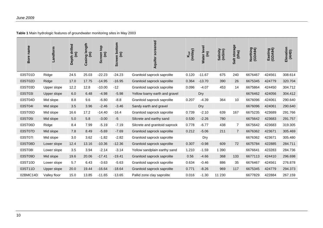
3.1 Profile descriptions Bore site names and locations are shown in Figure 1, with the detailed descriptive drill logs for each site in Appendix 1. Appendix 2 contains the EC1:5, EM39 and Gamma profile logs for each site. Appendix 3 details the laboratory analysis results of all drilling samples collected. Table 1 summarises the main features of each of the bores, together with their initial water levels and salinities. It also includes details of the additional site 02BMC14, drilled in 2002.
At all sites except 03ST10 there is a horizon of soft yellow sandy earth extending from the surface to between 0.5 and 3.5 m depth. This was composed of poorly sorted (bioturbated), sub-angular quartz grains of < 2 mm size, typical of the remnants of the Tertiary aeolian sandsheets of the district. This layer increased in thickness with lower landscape position, with 03ST08 having the thickest sand horizon. In the more elevated locations the sand was underlain by up to 5 m thickness of ironstone gravels. This was cemented and harder towards its lower extent, except at sites 03ST01 and 03ST06 where it was soft for over the full thickness, being comprised of loose pisoliths. The ironstone layer was absent at sites 03ST03, 03ST05, 03ST08 and 03ST10.
Variably hard silcrete layers were encountered at all sites drilled except 03ST10, at depths between 2.9 m (03ST07) and 6.9 m (upper slope, 03ST11) beneath the sand and ironstone. At all sites where ironstone was present, there appeared to be a transition zone at the top of the silcrete between the pure cemented ironstone and the silcrete. The silcrete layer ranged from 0.9 m to 7.4 m in thickness.
Further investigation into the impact of silcrete on root and water penetration was undertaken at the Goodlands oil mallee site using tracer dye and excavation (Bennett et al. 2005b). It was found that while silcrete can cause the development of perched groundwater, it readily leaks and the capacity of this perched groundwater may only be 3–7 mm on a long-term annualised basis. Conversely, plant roots are unlikely to be able to penetrate the silcrete, limiting the soil depth/volume available for soil water extraction. This is likely to place restrictions on the potential productivity of the oil mallee system.
Silcrete is a lithological term for brittle intensely indurated rock comprising cemented quartz grains. Butt (1983) determined that the cement from a profile at Gabbin (about 50 km south-east of the study site) was aluminosilicate with Al/Si atomic ratios of 0.35–1. He found the cement was either amorphous (termed siliceous allophane) or partly crystalline (termed neo-formed kaolinite, or opaline silica where it formed within the saprolite). He reported that such cemented grits and saprolites are exposed in many breakaways in the northern Yilgarn Craton.
The silcrete encountered at the site is extremely hard and the upper layers composed of cemented sub-angular sand grains, probably formed by in situ cementation of the Tertiary sandsheet. The lower layers contained silicified in situ weathered pallid zone saprolite comprised of poorly sorted angular and sharp quartz grains to 5 mm in size. This material also had fabric similar to weathered granitic material and was the hardest silcrete horizon. This indicates that the silcrete has formed at the boundary of the Tertiary sands and the underlying weathered granitic saprolite.
June 2009
10
Table 1 Main hydrologic features of groundwater monitoring sites in May 2003 B
ore
nam
e
Land
form
Dep
th d
rille
d
(m)
Cas
ing
leng
th
(m)
Scre
en to
p
(m)
Scre
en b
otto
m
(m)
Aqu
ifer s
cree
ned
Ksa
t (m
/day
)
Wat
er le
vel
(m)
Salin
ity
(mS/
m)
Salt
stor
age
(t/
ha)
Nor
thin
g
(GD
A94
)
East
ing
(G
DA
94)
Elev
atio
n
(AH
D)
03ST01D Ridge 24.5 25.03 -22.23 -24.23 Granitoid saprock saprolite 0.120 -11.67 675 240 6676467 424561 308.614
03ST02D Ridge 17.0 17.75 -14.95 -16.95 Granitoid saprock saprolite 0.364 -13.70 390 26 6675345 424779 320.704
03ST03D Upper slope 12.2 12.8 -10.00 -12 Granitoid saprock saprolite 0.096 -4.07 453 14 6675864 424450 304.712
03ST03I Upper slope 6.0 6.48 -4.98 -5.98 Yellow loamy earth and gravel Dry 6676462 424056 304.412
03ST04D Mid slope 8.8 9.6 -6.80 -8.8 Granitoid saprock saprolite 0.207 -4.39 364 10 6676096 424061 290.640
03ST04I Mid slope 3.5 3.96 -2.46 -3.46 Sandy earth and gravel Dry 6676096 424061 290.640
03ST05D Mid slope 16.6 17.2 -14.40 -16.4 Granitoid saprock saprolite 0.739 -2.10 639 167 6675235 423689 291.766
03ST05I Mid slope 5.0 5.8 -3.00 -5 Silcrete and earthy sand 0.530 -2.26 780 6675642 423683 291.757
03ST06D Ridge 8.4 7.99 -5.19 -7.19 Silcrete and granitoid saprock 0.778 -6.77 438 7 6675642 423683 319.305
03ST07D Mid slope 7.8 8.49 -5.69 -7.69 Granitoid saprock saprolite 0.212 -5.06 211 7 6676362 423671 305.469
03ST07I Mid slope 3.0 3.62 -1.82 -2.82 Granitoid saprock saprolite Dry 6676362 423671 305.480
03ST08D Lower slope 12.4 13.16 -10.36 -12.36 Granitoid saprock saprolite 0.307 -0.98 609 72 6675784 422885 284.711
03ST08I Lower slope 3.5 3.94 -2.14 -3.14 Yellow sandplain earthy sand 1.210 -1.59 1 390 6676641 423283 284.736
03ST09D Mid slope 19.6 20.06 -17.41 -19.41 Granitoid saprock saprolite 0.56 -4.66 368 133 6677113 424410 296.698
03ST10D Lower slope 5.7 6.43 -3.63 -5.63 Granitoid saprock saprolite 0.634 -0.46 886 35 6676467 424561 276.878
03ST11D Upper slope 20.0 19.44 -16.64 -18.64 Granitoid saprock saprolite 0.771 -8.26 969 117 6675345 424779 294.373
02BMC14D Valley floor 15.0 13.85 -11.65 -13.65 Pallid zone clay saprolite 0.016 -1.30 11 230 6677829 422884 267.159
Marchagee Oil Mallee Study
11
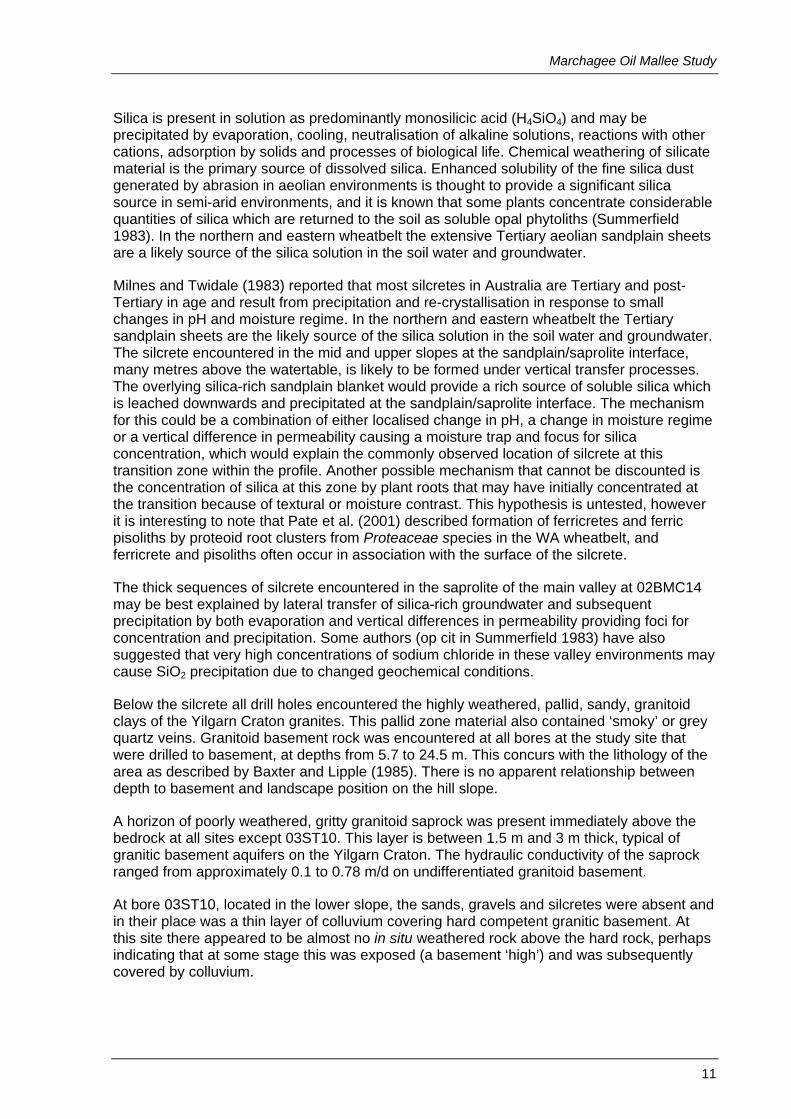
Silica is present in solution as predominantly monosilicic acid (H4SiO4) and may be precipitated by evaporation, cooling, neutralisation of alkaline solutions, reactions with other cations, adsorption by solids and processes of biological life. Chemical weathering of silicate material is the primary source of dissolved silica. Enhanced solubility of the fine silica dust generated by abrasion in aeolian environments is thought to provide a significant silica source in semi-arid environments, and it is known that some plants concentrate considerable quantities of silica which are returned to the soil as soluble opal phytoliths (Summerfield 1983). In the northern and eastern wheatbelt the extensive Tertiary aeolian sandplain sheets are a likely source of the silica solution in the soil water and groundwater.
Milnes and Twidale (1983) reported that most silcretes in Australia are Tertiary and post-Tertiary in age and result from precipitation and re-crystallisation in response to small changes in pH and moisture regime. In the northern and eastern wheatbelt the Tertiary sandplain sheets are the likely source of the silica solution in the soil water and groundwater. The silcrete encountered in the mid and upper slopes at the sandplain/saprolite interface, many metres above the watertable, is likely to be formed under vertical transfer processes. The overlying silica-rich sandplain blanket would provide a rich source of soluble silica which is leached downwards and precipitated at the sandplain/saprolite interface. The mechanism for this could be a combination of either localised change in pH, a change in moisture regime or a vertical difference in permeability causing a moisture trap and focus for silica concentration, which would explain the commonly observed location of silcrete at this transition zone within the profile. Another possible mechanism that cannot be discounted is the concentration of silica at this zone by plant roots that may have initially concentrated at the transition because of textural or moisture contrast. This hypothesis is untested, however it is interesting to note that Pate et al. (2001) described formation of ferricretes and ferric pisoliths by proteoid root clusters from Proteaceae species in the WA wheatbelt, and ferricrete and pisoliths often occur in association with the surface of the silcrete.
The thick sequences of silcrete encountered in the saprolite of the main valley at 02BMC14 may be best explained by lateral transfer of silica-rich groundwater and subsequent precipitation by both evaporation and vertical differences in permeability providing foci for concentration and precipitation. Some authors (op cit in Summerfield 1983) have also suggested that very high concentrations of sodium chloride in these valley environments may cause SiO2 precipitation due to changed geochemical conditions.
Below the silcrete all drill holes encountered the highly weathered, pallid, sandy, granitoid clays of the Yilgarn Craton granites. This pallid zone material also contained ‘smoky’ or grey quartz veins. Granitoid basement rock was encountered at all bores at the study site that were drilled to basement, at depths from 5.7 to 24.5 m. This concurs with the lithology of the area as described by Baxter and Lipple (1985). There is no apparent relationship between depth to basement and landscape position on the hill slope.
A horizon of poorly weathered, gritty granitoid saprock was present immediately above the bedrock at all sites except 03ST10. This layer is between 1.5 m and 3 m thick, typical of granitic basement aquifers on the Yilgarn Craton. The hydraulic conductivity of the saprock ranged from approximately 0.1 to 0.78 m/d on undifferentiated granitoid basement.
At bore 03ST10, located in the lower slope, the sands, gravels and silcretes were absent and in their place was a thin layer of colluvium covering hard competent granitic basement. At this site there appeared to be almost no in situ weathered rock above the hard rock, perhaps indicating that at some stage this was exposed (a basement ‘high’) and was subsequently covered by colluvium.
June 2009
12
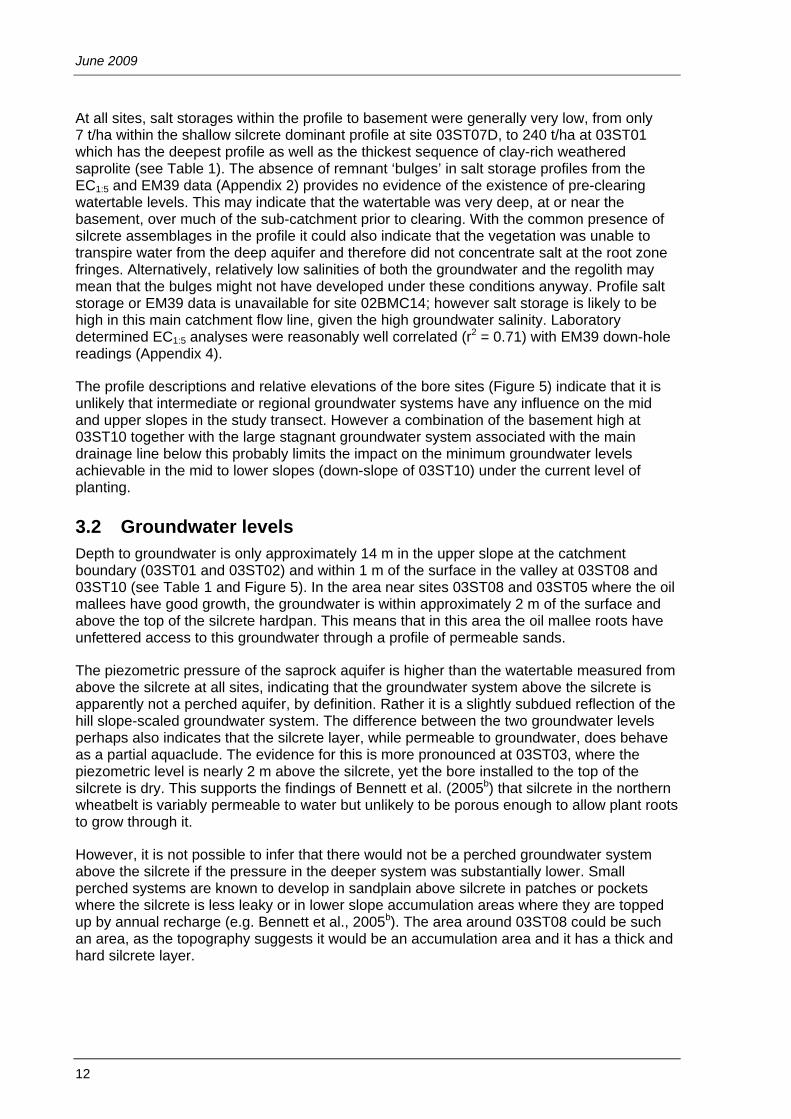
At all sites, salt storages within the profile to basement were generally very low, from only 7 t/ha within the shallow silcrete dominant profile at site 03ST07D, to 240 t/ha at 03ST01 which has the deepest profile as well as the thickest sequence of clay-rich weathered saprolite (see Table 1). The absence of remnant ‘bulges’ in salt storage profiles from the EC1:5 and EM39 data (Appendix 2) provides no evidence of the existence of pre-clearing watertable levels. This may indicate that the watertable was very deep, at or near the basement, over much of the sub-catchment prior to clearing. With the common presence of silcrete assemblages in the profile it could also indicate that the vegetation was unable to transpire water from the deep aquifer and therefore did not concentrate salt at the root zone fringes. Alternatively, relatively low salinities of both the groundwater and the regolith may mean that the bulges might not have developed under these conditions anyway. Profile salt storage or EM39 data is unavailable for site 02BMC14; however salt storage is likely to be high in this main catchment flow line, given the high groundwater salinity. Laboratory determined EC1:5 analyses were reasonably well correlated (r2 = 0.71) with EM39 down-hole readings (Appendix 4).
The profile descriptions and relative elevations of the bore sites (Figure 5) indicate that it is unlikely that intermediate or regional groundwater systems have any influence on the mid and upper slopes in the study transect. However a combination of the basement high at 03ST10 together with the large stagnant groundwater system associated with the main drainage line below this probably limits the impact on the minimum groundwater levels achievable in the mid to lower slopes (down-slope of 03ST10) under the current level of planting.
3.2 Groundwater levels Depth to groundwater is only approximately 14 m in the upper slope at the catchment boundary (03ST01 and 03ST02) and within 1 m of the surface in the valley at 03ST08 and 03ST10 (see Table 1 and Figure 5). In the area near sites 03ST08 and 03ST05 where the oil mallees have good growth, the groundwater is within approximately 2 m of the surface and above the top of the silcrete hardpan. This means that in this area the oil mallee roots have unfettered access to this groundwater through a profile of permeable sands.
The piezometric pressure of the saprock aquifer is higher than the watertable measured from above the silcrete at all sites, indicating that the groundwater system above the silcrete is apparently not a perched aquifer, by definition. Rather it is a slightly subdued reflection of the hill slope-scaled groundwater system. The difference between the two groundwater levels perhaps also indicates that the silcrete layer, while permeable to groundwater, does behave as a partial aquaclude. The evidence for this is more pronounced at 03ST03, where the piezometric level is nearly 2 m above the silcrete, yet the bore installed to the top of the silcrete is dry. This supports the findings of Bennett et al. (2005b) that silcrete in the northern wheatbelt is variably permeable to water but unlikely to be porous enough to allow plant roots to grow through it.
However, it is not possible to infer that there would not be a perched groundwater system above the silcrete if the pressure in the deeper system was substantially lower. Small perched systems are known to develop in sandplain above silcrete in patches or pockets where the silcrete is less leaky or in lower slope accumulation areas where they are topped up by annual recharge (e.g. Bennett et al., 2005b). The area around 03ST08 could be such an area, as the topography suggests it would be an accumulation area and it has a thick and hard silcrete layer.

Marchagee Oil Mallee Study
13
Figure 5 Hydrologic cross-section along the bore transect.
(vertical exaggeration = 30:1)
250
260
270
280
290
300
310
320
330
0 500 1000 1500 2000 2500 3000 3500 4000Distance from Catchment Crest (m)
m A
HD
Ground surfaceIronstone topSilcrete topSilcrete bottomSaprock topBasementScreen topScreen bottomPiezometric head (May 03)Watertable (May 03)Casing topTree rows
Main flowline
03 S
T02
03ST
05
03ST
03
03ST
08
03ST
10
BM
C14
Seep
390 mS/m
453 mS/m
639 mS/m
780 mS/m
609 mS/m
1390 mS/m
886 mS/m
Basement inferred

June 2009
14
3.3 Groundwater quality In general the groundwater is brackish, within the range 370 to 1390 mS/m (see Table 1). The deep saprock aquifer has reasonable quality for the district, although it is likely to deliver only a meagre supply rate. Bore 03ST09 is the best prospect for a reliable supply, having delivered approximately 0.5 L/sec of flow during air development at drilling, and being of suitable quality for dry adult sheep and cattle.
The generally relatively fresh groundwater in mid and upper slope positions (together with low salt storages) is most likely the consequence of relatively shallow profiles, the sandy texture soils allowing recharge, and the absence of discharge in these areas. By contrast, bore 02BMC14, which is located in the primary saline valley discharge area, is hyper-saline, having an EC of approximately 11 000 mS/m. Bore 03ST10, which is located near the head of the sub-catchment discharge, is relatively fresh (approximately 900 mS/m), indicating that the watertable has not been close to the surface for a long period and that the shallow watertable conditions are a relatively recent phenomenon in this area. If evapo-concentration had been occurring over a long period in this location, the groundwater salinity could be expected to be much higher, particularly given the clayey profile and absence of saprock aquifer.
Where saturated conditions exist above the silcrete layer, the groundwater has higher salinity than the deeper system. This supports the hypothesis that there is a single groundwater system on the hill slope, with the silcrete acting as a partial aquaclude only. If it was a perched system it would be expected that the groundwater would be much fresher than that contained in the deeper system, given the sandy texture and that it has always been beyond the reach of evapo-concentration influences. Since clearing, the influence of evaporation on the groundwater salinity above the silcrete is probably negligible in the mid slope because the watertable is more than 2 m below ground (03ST05). Even at 03ST08, where the watertable is only approximately 1.5 m down, there is unlikely to be a strong evaporative influence owing to the porous nature of the sandy profile above it.
However, direct transpiration of the watertable by the mallees is a possibility in these locations because it is likely to be fresh enough and is within easy reach of their root systems. This could explain the slightly elevated watertable salinity at 03ST05 and the almost doubling of salinity at 03ST08 (both relative to the deeper groundwater). If this trend continues over time it is possible that the watertable will become too saline to be directly used by the trees.
3.4 Geophysics EM38 mapping (see Figure 6) shows high root zone soil salinity levels (up to 500 mS/m) along the edge of the sub-catchment drainage line. There are also areas with high apparent electrical conductivity (ECa) readings extending from the head of the current discharge area (03ST10) into the adjacent paddocks. These areas confirm visual evidence of salinity, including bare and waterlogged areas and some barley grass, in the paddock to the north and the north-east of the sub-catchment drainage line. However to the east and south (around 03ST08) where the EM38 readings also indicate high conductivity, there is no visual sign of salinity. In the latter areas, the instrument signal may penetrate deep enough to respond to elevated conductivity due to the moisture from the watertable as well as the salts contained in the groundwater.
The area of elevated conductivity in the north-west corner (near the Vanzetti Road and Buntine–Marchagee Road intersection) corresponds to a saline discharge area. However the strip of apparently high conductivity (near 03ST01 and 03ST11) and the area east of 03ST06

Marchagee Oil Mallee Study
15
is spurious and is likely caused by the iron-rich lateritic cap rock present in this area. The occurrence of this cap rock approximates the areas with high EM38 response. Within these areas the watertable is deep and there is no visual evidence of salinity.
EM38 levels above 50 mS/m, particularly when combined with waterlogging, have been shown to adversely impact on growth rates of salt-sensitive pasture and trees (e.g. Bennett and George 1995). This EM38 survey indicates that there is no soil salinity in the mid and upper slope yellow sandplain areas at the site.
The EM31 measures soil salinity to about 6 m and can be a useful indication of salinity risk. Figure 7 shows that the EM31 signature generally matches the EM38 result but shows a larger area of high conductivity as would be expected from the greater depth. The EM31 more clearly defines the salinity risk in the valley section as it delineates areas with elevated salt store that currently have no evidence of shallow or surface salinity. The EM31 map also additionally defines zones within the upland sandplain that have a slightly elevated response. It is unlikely that these are salinity related but may be providing an indication of areas that have elevated moisture associated with saturated conditions above the silcrete within the instruments depth of penetration. More investigation is required to determine whether there is a relationship between EM31 and the depth to silcrete or the presence of saturated conditions in sandplain. This would be useful because if such a relationship exists, the EM31 could map these areas to help site mallee plantings to more effectively use this available water.
The magnetic survey image (Figure 8) indicates the presence of magnetic lineaments that trend north to south (near 03ST04 and 03ST05); north-north-west to south-south-east (near 03ST10 and 03ST07); and east-east-north to west-west-south (south of 03ST08 and 03ST04). These are likely to indicate structure within the basement geology; however it is not definitive because of the limited lateral extent of the survey. The shallow basement observed at 03ST10 could be associated with the two parallel lineaments each side of this location that apparently cross the sub-catchment drainage line.
There are no apparent large-scale magnetic anomalies that would indicate large-scale basement geological change. The discontinuous or ‘stippled’ areas of high magnetic signature to the east of 03ST06 and near 03ST11 to 03ST01 (and further south) are likely to be caused by an increased proportion of (magnetic) ironstone cap rock in the profile, as also indicated for the EM38 and EM31 responses.
Detailed radiometric and soil-matching analysis was not undertaken, however the radiometric total count image (Figure 9) provides some useful initial information. The dark blue areas (low count rate) appear to define areas of deeper sandplain very well. The very high count areas (red colouring) to the north of 03ST10 and west of 03ST06 correspond to areas containing granitoid and dolerite fragments and boulders on the soil surface, together with some outcrop. These are therefore likely to be areas where the underlying granite is very close, with associated soil profiles composed of relatively freshly weather granite, causing the high radiometric count. The high total count in the areas near 03ST11 and 03ST01 is likely caused by the contribution of uranium and thorium from soils with a high proportion of ironstone near the surface. These areas almost disappear from the image of the count derived from the potassium channel only (Figure 10). There the ironstone-rich areas are no longer prominent in the image because they have a low potassium signature.
It appears that radiometric survey techniques combined with the EM31 survey may be useful to distinguish deep sands containing relatively shallow groundwater from both shallow granitic and rocky ironstone soils. For example, the dark blue areas identified in Figure 7 appear to be well matched to areas of mallees that have the best growth. Conversely, areas

June 2009
16
with the poorest growth appear to coincide with rocky ironstone areas that were also identified using the geophysical techniques. Ground-based geophysics could therefore be a useful tool to target mallee plantings by helping to distinguish areas where highest growth rates can be expected.
The relationship between EM, magnetics, radiometrics and depth to silcrete and mallee growth was the subject of a more detailed study at the Goodlands oil mallee study site. There, Pracilio et al. (2006) found that mallee height was successfully modelled with radiometric and topographic data, with those factors accounting for 76% of the variance in mallee height. The tallest mallees were associated with soils of low radiometric counts and these soils were within the sandplain landform indicating a profile dominated by quartz and commonly identified by low radiometric counts. However at that site, the inclusion of EM31 data, as a surrogate measure of the presence of a shallow watertable (above the silcrete), did not improve the predictive capacity of the model. The ability to remotely and rapidly define areas of sandplain soils that have readily accessible watertables that can be used by mallees to grow faster warrants further investigation. This is because studies have shown that without an extra water supply, above that provided by annual rainfall, mallee growth rates in the wheatbelt are likely to be below levels required to sustain large-scale commercial viability of biomass industry (Cooper et al. 2005).

Marchagee Oil Mallee Study
17
Figure 6 EM38 image of study site.

June 2009
18
Figure 7 EM31 image of study site.

Marchagee Oil Mallee Study
19
Figure 8 Magnetic intensity image of study site.

June 2009
20
Figure 9 Total count radiometric image of study site.

Marchagee Oil Mallee Study
21
Figure 10 Potassium channel radiometric image of study site.

June 2009
22
3.5 Flowtube modelling
3.5.1 Basement aquifer Preliminary Flowtube modelling of the main transect from 03ST02D to the primary salt lake below 03ST10D was undertaken to assess the likely groundwater equilibrium condition and the impacts of the current oil mallee planting. The Flowtube model is a two-dimensional cross-sectional transient groundwater model, based on Darcian flow rules (Dawes 2000 and Argent et al. 2001). Flowtube has been used previously in several catchments to predict equilibrium groundwater conditions and the impact of a range of treatments (George et al. 2001). It has also been used in the Toolibin catchment as a comparison to predictions made using another groundwater model, MAGIC (Mauger 1996). Both models agreed closely in their predictions of equilibrium extent and treatment response (Dogramaci et al. 2003). More recently, George et al. (2004) and George and Bennett (2004) used Flowtube to predict that a valley recharge reduction focus was likely to be more effective in managing salinity than a hill slope focus at several wheatbelt sites.
Drill log descriptions and hydraulic conductivity measurements (see Table 1) were used to set the aquifer conditions for the model. The main parameters used in the model were:
• The weathered basement saprock aquifer was assumed to be the main controlling aquifer.
• The measured saturated hydraulic conductivities of the saprock aquifer at each bore location were used (ranged from 0.1 to 0.74 m/day).
• The model upper layer (saprolite) porosity was set at 0.1. • The model upper layer (saprolite) hydraulic conductivity was 0.05 m/day. • The maximum evaporation depth of 1 m was chosen because of the predominance of
deep sandy soils along the transect. • The area was cleared in 1955. • The watertable at clearing was assumed to be within 1 m of the basement in the mid
and upper slopes and 1 m below the ground surface at the primary salt lake at the end of the flowtube.
• The constant head point chosen was at bore BMC14D (266.6 m elevation at distance 875 m).
The model was run from assumed watertables present at clearing in 1955 to the present day under different recharge scenarios. Groundwater levels generated by the model were compared to current observed levels, and rates of rise were compared to those previously reported in the district. An average annual recharge rate of 25 mm/yr after clearing resulted in model results that most closely matched the observed current rates and watertable levels. Under this level of recharge the modelled watertable was within 0.5 m of observed levels at every bore along the flowtube. Modelled rates of watertable rise were between 0.1 m/yr (upper slope) and 0.2 m/yr (mid slope) which are consistent with reported rates (e.g. Speed and Strelein 2004) in the district up to the year 2000.
The model was run for 50 and 100 years (from present) under current recharge conditions and various scenarios of recharge/groundwater use. The two-row mallee belts (spaced at 120 m) were modelled to have a 20 m wide zone of influence on recharge/groundwater. This is approximately a 9 m wide influence either side of the belt. Wildy et al. (2004) and Robinson et al. (2003) report mallee belts having influence on soil water storage at distances from the belt of between 9 and 15 m. While our zone of influence is at the lower end of this range it must be remembered that we modelled scenarios ranging from recharge being

Marchagee Oil Mallee Study
23
completely eliminated to high rates of net groundwater usage in this zone, not just some soil water extraction and partial recharge elimination. The four scenarios of oil mallee groundwater use modelled were: recharge is reduced to zero, and recharge is reduced to zero plus an additional groundwater usage of 50 mm, 100 mm and 200 mm. The results are displayed graphically in Figure 11 and indicate that:
• Currently, shallow watertables affect 59 per cent of the modelled flowtube. • Without treatment, groundwater levels in the mid slope can be expected to rise slightly
to be within 1 m of the surface over 66 per cent of the flowtube length within 50 years. Very little change is expected between 50 and 100 years with the model indicating 68 per cent affected. Groundwater levels are expected to remain static in the lower slopes from now on, with levels expected to rise approximately a further 4 m in the mid and upper slopes at equilibrium. This continued rise does not correspond to a significant increase in the affected length of the flowtube.
• If the mallees prevent recharge over a 20 m width at each belt then watertables would be expected to be slightly above current levels in 50 years and affect 62 per cent of the flowtube.
• If the mallees use an additional 50 mm of groundwater, watertables would be slightly below current levels after 50 years (56% of transect affected).
• If the mallees use an additional 100 mm of groundwater, watertables will fall so that 44 per cent of the flowtube would remain affected. However the area down-slope of ST08D would continue to have a shallow watertable.
• If the mallees use an additional 200 mm of groundwater, watertables will fall substantially to almost eliminate shallow groundwater from the flowtube above the soak. However watertables would remain unaffected below bore 03ST10D (37% of transect affected).
The modelling indicates that high (> 100 mm annually) groundwater use by the mallees over a 20 m wide strip along each alley is required to substantially change the area affected by shallow watertables in this catchment. This is additional to the mallees using the whole annual addition of soil moisture from rainfall before it becomes recharge. One hundred millimetres of groundwater use within a 20 m wide strip equates to approximately 17 mm of annual groundwater use across the whole catchment, only 8 mm less than the modelled long-term average recharge that led to the current watertable extent.
The primary reasons for the poor responses are the low gradient of the watertable and the thin aquifer near bore 03ST10D, which mean that the aquifer has a low capacity to transmit groundwater out of the system. For the same reasons it appears that the watertable at the soak will not diminish much under even the highest water use scenario. However the gradient towards the soak will reduce substantially, possibly limiting the rate of groundwater supply for this resource.
It is unlikely that the mallees will be able to access more than about 50 mm of groundwater annually upslope of 03ST05D because at greater usage levels the watertable will remain below the silcrete layer (as shown in Figure 11), which is unlikely to be able to be penetrated by their roots. Between 03ST08D and 03ST10D, the aquifer has the capacity to maintain the watertable above the silcrete provided rates of water use are below 200 mm annually. An annual 200 mm of groundwater use by the oil mallees is feasible in this location because of the shallow proximity of the watertable, the quality of the groundwater (780–1390 mS/m) and the sandy profile. Evidence of this potential can be currently observed by the higher growth rates of the mallees in this area. However continued evapo-transpiration from the watertable could mean that the quality of the groundwater may rapidly deteriorate over time. Already,

June 2009
24
the groundwater above the silcrete layer (and influenced by evapo-transpiration) at 03ST08D is approximately twice as saline as the groundwater in the deeper system.
3.5.2 Perched aquifer The perched groundwater system that can develop above the silcrete may provide a groundwater resource for the mallees. The Flowtube model for the site (reported above) has been calibrated without considering perched water use having an impact on the recharge to the deeper system. That is, it assumes that a perched system may develop but it then leaks into the deeper system. This may not be the case under the mallee system if the trees are able to rapidly use the perched water and thus effectively take up some of the water before it can enter the deep system, so preventing a proportion of recharge. Modelling was undertaken to determine the likely annual average amount of water that the perched system might account for over time. A short Flowtube model was constructed which assumed for the purposes of this test that the silcrete layer was the bottom of the aquifer and did not leak. The main parameters were:
• The maximum evaporation depth of 1 m was used because of the predominance of sandy loam soils above the silcrete.
• The saturated hydraulic conductivity is 0.54 m/d, which is the mean of all measurements made of perched systems that had an ironstone gravel layer above the silcrete—from this site and the Goodlands site (Bennett et al. 2005a).
• The upper layer porosity is 0.2 for the yellow sandy earth material. • The upper layer hydraulic conductivity is 0.2 m/day, which is also the mean of
measurements made in yellow sandplain soils. • The area was cleared in 1955. • The perched watertable was assumed to be dry at clearing.
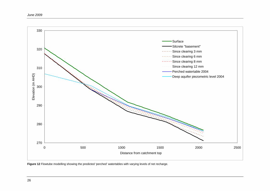
The model was run for 50 years with various recharge levels. ‘Recharge’ in this instance was interpreted as the annual amount of water that is left within the ‘perched’ system after leakage through the silcrete. In the upper slope, the results indicate (Figure 12) that less than 3 mm of annual ‘recharge’ was required for the model to mimic the current situation (absence of perched watertable in upper slope).
In the mid and lower slopes it would appear that the current watertable can be explained by the modelling scenario, which has approximately 8 mm of annual ‘recharge’ captured above the silcrete. However comparison of the observed piezometric surface of the deep aquifer system with the watertable (Figure 5) indicates that there is actually upward head potential from the deep to the ‘perched’ systems wherever there is an apparent ‘perched’ system developed. This means that the ‘perched’ system could be explained by discharge from the deeper system alone, however it is most likely a combination together with in situ recharge. It is therefore unlikely to be a true perched system, rather is the expression of the deep groundwater leaking up through the silcrete layer, which indicates this is not behaving as a partial aquaclude. Alternatively (and at the very least), the observed ‘perched’ system develops because pressure from the deeper system prevents downward leakage.
It should be noted that any perched systems that may develop are much more likely to develop intermittently under high recharge events (Speed 2004) and this modelling does not represent the actual mechanisms of perched system development. However it indicates the long-term annual average capacity of the perched system and the amount of water available for the mallees and therefore possibly not available for recharge to the deep system. At this site it appears that this capacity is less than 3 mm on a long-term, annualised basis.

Marchagee Oil Mallee Study
25
Figure 11 Flowtube modelling showing the predicted piezometric surfaces along the transect.
230
240
250
260
270
280
290
300
310
320
330
0 500 1000 1500 2000 2500 3000 3500
Distance from catchment top
Elev
atio
n (m
AH
D)
SurfaceCurrent (50 yrs since clearing), 59%Forecast 50 years without oil mallees, 66%Forecast 100 years without oil mallees, 68%Mallees prevent recharge over 20 m width, 62%Mallees use 50 mm groundwater over 20 m width, 56%Mallees use 100 mm groundwater over 20 m width, 44%Mallees use 200 mm groundwater over 20 m width, 37%Silcrete TopBasement
(vertical exaggeration ~ 35:1)
June 2009
26
Figure 12 Flowtube modelling showing the predicted ‘perched’ watertables with varying levels of net recharge.
270
280
290
300
310
320
330
0 500 1000 1500 2000 2500
Distance from catchment top
Elev
atio
n (m
AH
D)
SurfaceSilcrete "basement"Since clearing 3 mmSince clearing 6 mmSince clearing 8 mmSince clearing 12 mmPerched watertable 2004Deep aquifer piezometric level 2004

Marchagee Oil Mallee Study
27
4. Conclusions This site is well suited for an intensive study of the impacts that wide-spaced belts of oil mallee plantings have on groundwater at the sub-catchment scale. The absence of saline soils and shallow saline watertables over most of the planting area mean that the trees should grow well. The non-acidic deep sandplain soils which cover much of the area represent soil types that are a potential focus of the oil mallee industry in the northern wheatbelt. The presence of silcrete underlying these soils is also very common. The silcrete may limit soil depth and volume available for exploitation by the mallees as it is unlikely that roots will be able to penetrate to explore the deeper moisture reserves or the deep groundwater system.
Flowtube modelling of the site shows that it is approaching hydrologic equilibrium and that while continued watertable rise may occur in the upper slopes, further large areas of soil salinity development is unlikely, given similar rainfall conditions to those since clearing. The current oil mallee configuration would need to prevent all recharge and use more than an additional 100 mm of groundwater from a strip 20 m wide beneath the planted alleys to reduce watertables appreciably and reduce the amount of land affected by shallow watertables. While this may be theoretically possible given the moderate salinities of the groundwater, additional groundwater use is unlikely to occur over most of the sub-catchment because of the prevalent silcrete layer. This is likely to be a physical barrier to root exploration and mean that the mallee roots will not have access to the watertable over most of the planted areas. In these areas the mallee impact will therefore only likely be to reduce recharge by a factor proportionate to the area planted plus the area of lateral root exploration.
Even if high rates of groundwater use was possible across the whole area planted with mallee belts, the current shallow groundwater and associated salinity in the mid to lower slope areas of the sub-catchment would be likely to remain. This is because the combination of low groundwater gradient, a basement high that severely restricts the aquifer thickness, and the large stagnant groundwater system associated with the main drainage line below, greatly restricts the capacity of the groundwater system to drain in the area below the planting.
The potential for perched groundwater systems to sporadically develop on the silcrete following intense, episodic rainfall offers an additional small water source for the trees. At this site permanent perched systems are absent, however their existence could be masked by the outcrop of the deeper groundwater system above the silcrete in the mid slope areas. Flowtube modelling indicated that should they exist, the long-term average annual capacity of these perched systems is small, in the order of only a few millimetres. The presence, depth and extent of silcrete are very important factors for the oil mallee industry to consider in the region, as silcrete is common and has the capacity to limit the potential for oil mallee growth.
It appears that the radiometric survey techniques combined with EM31 survey may be useful to distinguish deep sands containing relatively shallow groundwater, from both shallow granitic and rocky ironstone soils. Ground-based geophysics could therefore be a useful tool to target mallee plantings by helping to distinguish areas where highest growth rates can be expected.

June 2009
28
5. References Anon (2005) Draft Buntine Marchagee Natural Diversity Recovery Catchment Recovery Plan
2005–2010. Department of Conservation and Land Management. Argent RM, George RJ and Dawes W (2001) Flowtube: a groundwater calculator for salinity
estimation. In: Ghassemi F, Whetton P, Little R and Littleboy M (eds), 2001 MODSIM 2001 International Congress on Modelling and Simulation. Modelling and Simulation Society of Australia and New Zealand Inc., Canberra, 621–6.
Baxter JL and Lipple SL (1985) Perenjori, Western Australia, 1:250 000 geological series—explanatory notes. Geological Survey of Western Australia.
Bennett DL and George RJ (1995) Using the EM38 to measure the effect of soil salinity on Eucalyptus globulus in south-western Australia. Agricultural Water Management 27: 69–86.
Bennett D, Speed R and Taylor P (2005a) Goodlands Marchagee oil mallee study: Drill completion and preliminary hydrogeological interpretation. Resource Management Technical Report No. 293. Department of Agriculture, WA.
Bennett D, Speed R, Taylor P and Goodreid A (2005b) Silcrete hardpan in the north-eastern wheatbelt: hydrological implications for oil mallees. Resource Management Technical Report No. 297. Department of Agriculture, WA.
Bouwer H and Rice RC (1976) A slug test for determining conductivity of unconfined aquifers with completely or partially penetrating wells. Water Resources Research 12(3): 423–8.
Butt CRM (1983) Aluminosilicate cementation of saprolites, grits and silcretes in Western Australia. Journal of the Geological Society of Australia 30: 179–86.
Carter JL, Ward P, White DA, Brooksbank K, Rance S and Walker S (2004) Water use and growth of oil-mallees with variation in groundwater availability. Salinity Solutions, Working with Science and Society. Conference Proceedings, Bendigo.
Commander DP and McGowan RJ (1991) Explanatory notes on the Perenjori 1:250 000 hydrogeological sheet. Geological Survey of Western Australia.
Cooper D, Olsen G and Bartle J (2005) Capture of agricultural surplus water determines the productivity and scale of new low-rainfall woody crop industries. Australian Journal of Experimental Agriculture 45 (11): 1369–88.
Cummings B and Hardy A (2000) Revision of the Interim Biogeographic Regionalisation of Australia (IBRA) and development of Version 5.1—Summary Report. National Reserves System Section. Environment Australia, Canberra, ACT.
Dawes WR, Stauffacher M and Walker GR (2000) Calibration and modelling of groundwater processes in the Liverpool Plains. CSIRO Land and Water Technical Report 5/00. Canberra, Australia.
Department of Natural Resources and Mines (2004) The data drill, climate impacts and natural resources systems. Queensland Department of Natural Resources and Mines. Data retrieved: March 2009 from database at http://www.nrm.qld.gov.au/silo/datadrill.
Dogramaci S, George R, Mauger G and Ruprecht J (2003) Water balance and salinity trend, Toolibin Catchment, Western Australia. Department of Environment Report. WA.
George RJ, Bennett DL and Speed RJ (2004) Salinity management—the case for focussing on wheatbelt valleys. Salinity Solutions, Working with Science and Society. Conference Proceedings, Bendigo.
George RJ and Bennett DL (2004) Impact of farm forestry systems on dryland salinity—a modelling case study. Australian Forestry Conference, Melbourne.

Marchagee Oil Mallee Study
29
George RJ, Clarke CJ and Hatton T (2001) Computer modelled groundwater response to recharge management for dryland salinity control in Western Australia. Journal of Environmental Monitoring and Modelling. Special Issue: Land Degradation in the Drylands 2(1): 1–35.
Griffin T and Goulding P (2004) Soil landscape mapping for the Buntine Marchagee recovery catchment. Land Resource and Monitoring. Resource Management Technical Report. Report produced by the Department of Agriculture for the Department of Conservation and Land Management.
Lewis MF (2000) The significance of episodic recharge in the wheatbelt of Western Australia. Doctoral Thesis, University of Melbourne.
Schoknecht N (2002) Soil groups of Western Australia: a simple guide to the main soils of Western Australia. 3rd edn. Resource Management Technical Report No. 246. Department of Agriculture, WA.
Speed R (2004) Personal communication of unpublished groundwater monitoring results. Speed RJ and Kendle AL (2008) Groundwater declines in response to a drier climate in the
Northern Agricultural Region of Western Australia. 2nd International Salinity Forum. Adelaide.
Speed R and Strelein M (2004) Groundwater investigation Buntine–Marchagee natural diversity recovery catchment. Resource Management Technical Report No. 282. Department of Agriculture, WA.
Mauger GW (1996) Modelling dryland salinity with the M.A.G.I.C. system. Water Resource Technical Series, Report No. WRT 7. Water and Rivers Commission, Perth.
Milnes AR and Twidale CR (1983) An overview of silicification in Cainozoic landscapes of arid central and southern Australia. Australian Journal of Soils Research 21: 387–410.
Pate JS, Verboom WH and Galloway PD (2001) Turner review No. 4: ‘Co-occurrence of Proteaceae, laterite and related oligotrophic soils: Coincidental associations or causative inter-relationships?’ Australian Journal of Botany 49: 529–60.
Pracilio G, Smettem KRJ, Bennett D, Harper RJ and Adams ML (2006) Site assessment of a woody crop where a shallow hardpan soil layer constrained plant growth. Plant and Soil 288: 113–25.
Robinson N, Harper RJ, Smettem KRJ and McGrath JF (2003) Tree placement strategies for salinity control in dryland farming systems of southern Australia. 13th International Soil Conservation Conference. Brisbane, Australia.
Summerfield MA (1983) Silcrete. In: Chemical sediments and geomorphology—precipitates and residua in the near surface environment (AS Goudie and K Pye, eds). Academic Press, London.
URS (2008) Hydrogeology investigation Buntine–Marchagee natural diversity recovery catchment. Report prepared for Department of Environment and Conservation, Geraldton.
Wildy DT, Pate JS and Bartle JR (2004) Budgets of water use by Eucalyptus kochii tree belts in the semi arid wheatbelt of Western Australia. Plant and Soil 262: 129–49.

June 2009
30
6. Appendixes
6.1 Field drill logs Site details
Date: 8/4/03 Landform/unit: Ridge top NE corner
Catchment/project/owner: John and Robin Stacy, Calecono, Buntine Marchagee catchment
Year cleared: 1955
Location number:
Local bore # : 03ST01D AMG northing (m): 6676467.001
W+R bore # AMG easting (m): 424561.207
Driller: Don Bennett, Adrian Goodreid AHD (m): 308.678
Depth (m) Sample description and drilling comments Geology
0 Light brown sand. Tertiary sandplain
0.9 Hard and cemented gravelly sand (ironstone pisoliths and ferricrete).
Ferricrete
4.5 Light brown sandy (quartz) gravel (ironstone); quartz grains to 4 mm and sub-rounded.
6.3 Very hard light grey cemented—small sharp quartz in an indurated ‘cement’—silcrete.
Silcrete
9 Micaceous clayey sand—orange/brown, quartz—sharp to 5 mm.
Weathered gneissic saprolite
10.2 Finer micaceous sandy clay, quartz to 2 mm.
11.5 As above but quite moist.
20 Lost circulation; water injected. Collapsing hole.
22.5 Getting crunchy now; fresh feldspars and quartz together.
24.5 Very hard basement; large feldspars to 10 mm with some quartz and mica. Basement gneiss.
Basement gneiss
Making a dribble of water.
Bore completion details
Depth drilled (m): 24.5 Water/foam/detergent injected (m): 20→
Casing total length (m): 25.03 Est. watertable during drilling (m): 11.5
AGL (m): 0.80 Casing installation: GOOD/OK/FORCED
Screen Length (m): 2.0 Estimated yield: Very low
Material screened: Saprock SWL at completion (m):
Drill method/bit diam. (mm): 120 RAB EC (mS/m): 2675
Casing type and diam. (mm): CL9 PVC 50 mm First SWL (m): 12.35 on 10/4/03

Marchagee Oil Mallee Study
31
Site details
Date: 8/4/03 Landform/unit: Ridge top SE corner
Catchment/project/owner: John and Robin Stacy, Calecono, Buntine Marchagee catchment
Year cleared: 1955
Location number:
Local bore #: 03ST02D AMG northing (m): 6675344.511
W+R bore # AMG easting (m): 424778.589
Driller: Don Bennett, Adrian Goodreid AHD (m): 320.686
Depth (m) Sample description and drilling comments Geology
0 Gravelly light brown sand. Tertiary sandplain
0.5 Hard ironstone, cemented, red/brown. Ferricrete. Ferricrete
2.2 Softer lighter brown sandy ironstone gravel.
3.0 Very hard silicified sand—silcrete. Silcrete
5.2 A bit softer but as above.
6.1 Very hard again now—lighter grey, some individual angular and sharp quartz grains to 5 mm, dry and dusty.
Silicified granitic saprolite
6.6 Softer and moist light brown clayey sand, very sharp quartz in a brown clay matrix. Contains some fine dark mica.
7.5 Harder again, light grey/brown indurated clay with numerous, small quartz, dusty and dry, still silcrete.
9–9.5 Band of above but heavily iron stained.
13.4 Soft-dark brown clayey grit. Contains quartz, feldspar and mica; moist.
Weathered granite saprock
14.7 Getting crunchy.
15.8 Getting very hard; iron-stained pieces of feldspar and quartz rich fresh rock coming up, damp. Micas present.
Basement granite
17 Pushed through to 17 m EOH granite basement.
Bore completion details
Depth drilled (m): 17.00 Water/foam/detergent injected (m): Nil
Casing total length (m): 17.75 Est. watertable during drilling (m): 13.0
AGL (m): 0.80 Casing installation: GOOD/OK/FORCED
Screen length (m): 2.00 Estimated yield: Very low
Material screened: Saprock SWL at completion (m):14.55
Drill method/bit diam. (mm): 120 RAB EC (mS/m): 390
Casing type and diam. (mm): 50 mm CL9 PVC First SWL (m): 14.30 on 10/4/03

June 2009
32
Site details
Date: 8/4/03 Landform/unit: Upper slope—in depression, 1st row in paddock
Catchment/project/owner: John and Robin Stacy, Calecono, Buntine Marchagee catchment
Year cleared: 1955
Location number:
Local bore #: 03ST03D + I AMG northing (m): 6675863.925
W+R bore # AMG easting (m): 424449.562
Driller: Don Bennett, Adrian Goodreid AHD (m): 304.728
Depth (m) Sample description and drilling comments Geology
0 Yellow/brown sandy earth. Tertiary sandplain
1.9 Very hard cemented ironstone gravel, dry. Ferricrete
4.1 Soft coarse (< 3 mm) fairly even sub-rounded quartz sand; dry.
Tertiary sandplain
5.6 Very hard silcrete. Light grey but with some minor layers of iron staining, dry and dusty.
Silcrete
8.9 Softer now, angular, sharp quartz grains in a gritty mottled orange/grey clay matrix, moist.
Silicified granitic saprolite
10 Lots of jagged quartz now with feldspars, getting very crunchy, dark brown and wet.
Weathered granite saprock
12.2 Drill refusal—basement granite—feldspars and quartz and minor micas.
Basement granite
Bore completion details
Depth drilled (m): 12.20 (6.00) Water/foam/detergent injected (m): Nil
Casing total length (m): 12.80 (6.48) Est. watertable during drilling (m): 8.9
AGL (m): 0.80 (0.50) Casing installation: GOOD/OK/FORCED
Screen length (m): 2.00 (1.00) Estimated yield: Very low
Material screened: Saprock SWL at completion (m): 11.70
Drill method/bit diam. (mm): 120 RAB EC (mS/m): 453 (Dry)
Casing type and diam. (mm): 50 mm CL9 PVC First SWL (m): 4.70 on 10/4/03 (Dry)

Marchagee Oil Mallee Study
33
Site details
Date: 8/4/03 Landform/unit: Mid slope 4th row in paddock
Catchment/project/owner: John and Robin Stacy, Calecono, Buntine Marchagee catchment
Year cleared: 1955
Location number:
Local bore #: 03ST04D and I AMG northing (m): 6676461.988
W+R bore # AMG easting (m): 424055.879
Driller: Don Bennett, Adrian Goodreid AHD (m): 290.595
Depth (m) Sample description and drilling comments Geology
0 Light brown/yellow loamy sand. Tertiary sandplain
0.2 Deep yellow sandy earth. 3.4 Hard quartz rich grey and light brown silcrete. Harder and
softer layers—generally not as hard as bores 1, 2 or 3. Has some moisture in layers within (not watertable).
Silcrete
6.0 Darker and softer, hard and soft layers, also chips are finer.
7.0 Dark brown clayey gritty sand. Uneven and sharp quartz to 5 mm plus minor micas in a damp dark clayey matrix, crunchy.
Weathered granitic saprolite
8.5 Very hard now—fine-grained granite rock fragments (quartz and feldspar).
Granitic saprock
8.8 Drill refusal—lifting rig—basement rock. Basement granite
I is 20 m N of D
≈ 30 cm higher
Bore completion details
Depth drilled (m): 8.80 (3.50) Water/foam/detergent injected (m): Nil
Casing total length (m): 9.60 (3.96) Est. watertable during drilling (m): 7.0
AGL (m): 0.80 (0.50) Casing installation: GOOD/OK/FORCED
Screen length (m): 2.0 (1.00) Estimated yield: Nil
Material screened: Saprock SWL at completion (m): 8.10 (dry)
Drill method/bit diam. (mm): 120 RAB EC (mS/m): 364 (dry)
Casing type and diam. (mm): 50 mm CL9 PVC First SWL (m): 4.98 on 10/8/03 (dry)

June 2009
34
Site details
Date: 8/4/03 Landform/unit: Mid slope—4th row in paddock
Catchment/project/owner: John and Robin Stacy, Calecono, Buntine Marchagee catchment
Year cleared: 1955
Location number:
Local bore #: 03ST05D and I AMG northing (m): 6676095.625
W+R bore # AMG easting (m): 424060.932
Driller: Don Bennett, Adrian Goodreid AHD (m): 291.762
Depth (m) Sample description and drilling comments Geology
0 Yellow sandy earth. Tertiary sandplain
2.3 Hard sub-rounded quartz rich silcrete, light brown/grey.
2.5 As above—quite moist.
3 Hard and soft layers, quite moist, some ferricrete. Free moisture returned at the 5 m rod change. Soft layers are coarse sub-rounded sand rich.
Silcrete
5.5 Hard again now, coming up as chips, no free water returning.
8.0 Making a dribble of water at the rod change. Indurated angular quartz rich grey clay—comes up as chips, hard and soft layers.
Silicified weathered saprolite
10.5 Softer grey sandy clay returning as chips with some < 10 mm angular quartz pieces.
Granitic saprolite
12 Turned darker brown.
13.8 Crunching—sharp and large (10 mm) quartz and feldspars. Granitic saprock
16.6 Drill refusal, fresh basement rock, quartz and feldspar and a finer olive green/dark grey mottling.
Basement granite
Making own water ¼ L/sec.
3 m samples (sloppy from 11 m)
Bore completion details
Depth drilled (m): 16.6 (5.0) Water/foam/detergent injected (m): Nil
Casing total length (m): 17.2 (5.8) Est. watertable during drilling (m): 2.5
AGL (m): 0.8 (0.8) Casing installation: GOOD/OK/FORCED
Screen length (m): 2 (2) Estimated yield: 0.25 L/sec
Material screened: Saprock (sand/silcrete) SWL at completion (m):
Drill method/bit diam. (mm): 120 RAB EC (mS/m): 639 (780)
Casing type and diam. (mm): 50 mm CL9 PVC First SWL (m): 2.67, (3.06) on 9/4/03

Marchagee Oil Mallee Study
35
Site details
Date: 9/4/03 Landform/unit: Ridge Top. South side 7th row in paddock
Catchment/project/owner: John and Robin Stacy, Calecono, Buntine Marchagee catchment
Year cleared: 1955
Location number:
Local bore #: 03ST06D AMG northing (m): 6675234.930
W+R bore # AMG easting (m): 423688.812
Driller: Don Bennett, Adrian Goodreid AHD (m): 319.297
Depth (m) Sample description and drilling comments Geology
0 Light brown sandy earth. Tertiary sandplain
0.2 Yellow sandy earth. 1.9 Ironstone gravels in a sandy matrix.
4.1 Hard deep-red cemented ironstone, ferricrete. Ferricrete
5.2 Soft light brown clayey sand, moist.
6.1 Very hard grey/light brown/red—sample returning as fine (2 mm) grains of quartz and cemented material, with some iron stains. Silcrete. Dry and dusty.
Silcrete
7.0 Softer layers now, fine sandy clay. Weathered granitic saprolite
8.4 ‘Smack’ onto impenetrable granite basement. Basement granite
Trouble getting casing in—collapsing gravels from above. Re-drilled and used water but to no avail.
Bore completion details
Depth drilled (m): 8.4 Water/foam/detergent injected (m): To lift gravel after finished.
Casing total length (m): 7.99 Est. watertable during drilling (m): ?
AGL (m): 0.80 Casing installation: GOOD/OK/FORCED
Screen length (m): 2.0 Estimated yield:
Material screened: Fine sandy clay SWL at completion (m):
Drill method/bit diam. (mm): 120 RAB EC (mS/m): 438
Casing type and diam. (mm): 50 mm CL9 PVC First SWL (m): 6.94 on 10/4/03
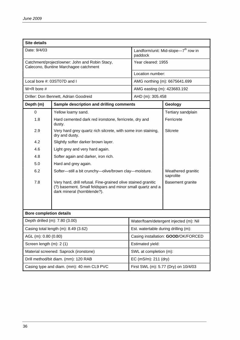
June 2009
36
Site details
Date: 9/4/03 Landform/unit: Mid-slope—7th row in paddock
Catchment/project/owner: John and Robin Stacy, Calecono, Buntine Marchagee catchment
Year cleared: 1955
Location number:
Local bore #: 03ST07D and I AMG northing (m): 6675641.699
W+R bore # AMG easting (m): 423683.192
Driller: Don Bennett, Adrian Goodreid AHD (m): 305.458
Depth (m) Sample description and drilling comments Geology
0 Yellow loamy sand. Tertiary sandplain
1.8 Hard cemented dark red ironstone, ferricrete, dry and dusty.
Ferricrete
2.9 Very hard grey quartz rich silcrete, with some iron staining, dry and dusty.
Silcrete
4.2 Slightly softer darker brown layer.
4.6 Light grey and very hard again.
4.8 Softer again and darker, iron rich.
5.0 Hard and grey again.
6.2 Softer—still a bit crunchy—olive/brown clay—moisture. Weathered granitic saprolite
7.8 Very hard, drill refusal. Fine-grained olive stained granitic (?) basement. Small feldspars and minor small quartz and a dark mineral (hornblende?).
Basement granite
Bore completion details
Depth drilled (m): 7.80 (3.00) Water/foam/detergent injected (m): Nil
Casing total length (m): 8.49 (3.62) Est. watertable during drilling (m):
AGL (m): 0.80 (0.80) Casing installation: GOOD/OK/FORCED
Screen length (m): 2 (1) Estimated yield:
Material screened: Saprock (ironstone) SWL at completion (m):
Drill method/bit diam. (mm): 120 RAB EC (mS/m): 211 (dry)
Casing type and diam. (mm): 40 mm CL9 PVC First SWL (m): 5.77 (Dry) on 10/4/03

Marchagee Oil Mallee Study
37
Site details
Date: 9/4/03 Landform/unit: Lower slope—just above seep
Catchment/project/owner: John and Robin Stacy, Calecono, Buntine Marchagee catchment
Year cleared: 1955
Location number:
Local bore #: 03ST08 D and I AMG northing (m): 6676362.434
W+R bore # AMG easting (m): 423671.015
Driller: Don Bennett, Adrian Goodreid AHD (m): 284.789
Depth (m) Sample description and drilling comments Geology
0 Yellow loamy sand—moist. Tertiary sandplain
2 As above but wet and sloppy—coarse sand.
3.5 Very hard silcrete—mottle grey and red (collar in to 3.5 m). Silcrete
4.9 As above but a bit softer.
6.5 Light brown indurated sandy clay—hard layers with iron staining.
8.2 Very hard grey fine silcrete again.
10.9 Softer quartz rich gritty clay—sharp, angular quartz with fabric.
Weathered granitic saprolite
12.0 Very hard—quartz and feldspar chips plus fine-grained dark (black) mineral. Mud turned olive colour.
Saprock
12.36 Drill refusal. Making ¼ L/sec. Basement granite
Collar to 3.5 m.
Bore completion details
Depth drilled (m): 12.36 (3.50) Water/foam/detergent injected (m): Nil
Casing total length (m): 13.16 (3.94) Est. watertable during drilling (m): 2
AGL (m): 0.80 (0.80) Casing installation: GOOD/OK/FORCED
Screen length (m): 2 (1) Estimated yield: 0.25 L/sec
Material screened: Saprock (sand) SWL at completion (m): 1.60
Drill method/bit diam. (mm): 120 RAB EC (mS/m): 609 (1390)
Casing type and diam. (mm): 50 mm CL9 PVC First SWL (m): 1.52 (2.40)

June 2009
38
Site details
Date 10/4/03 9:00 am Landform/unit: Mid slope—control
Catchment/project/owner: John and Robin Stacy, Calecono, Buntine Marchagee catchment
Year cleared: 1955
Location number:
Local bore #: 03ST09D—Control AMG northing (m): 6675783.903
W+R bore # AMG easting (m): 422884.712
Driller: Don Bennett, Adrian Goodreid AHD (m): 296.665
Depth (m) Sample description and drilling comments Geology
0 Yellow loamy sand Tertiary sandplain
1.9 Ironstone gravelly (pisoliths) sand.
2.1 Cemented ironstone—hard. Ferricrete
2.5 Lightly indurated mottled orange/grey sandy clay.
3.1 Hard grey indurated gritty (quartz) clay—dry and dusty—silcrete? Has some pink/red iron-stained seams.
Silcrete
6.0 A bit softer and moist—brown/grey.
6.7 Hard again and dusty dry grey.
8.5 Softer but still crunchy—moist. Large quartz (to 10 mm) chips in a brown clay matrix.
Weathered granitic saprolite
10.5 Dark brown and crunchy—quartz and feldspars.
11.2 Lighter brown—very gritty, quartz and feldspar chips to 15 mm.
14.0 Making sloppy muddy water now—3 m samples.
17.0 Making ½ L/sec—huge (20 mm) pieces of quartz and feldspar—fault zone?
Saprock
19.5 Drill refusal—altered granite or gneiss Gneissic basement
Bore completion details
Depth drilled (m): 19.6 Water/foam/detergent injected (m): Nil
Casing total length (m): 20.06 Est. watertable during drilling (m): 8.5
AGL (m):0.65 Casing installation: GOOD/OK/FORCED
Screen length (m): 2.0 Estimated yield: 0.5 L/sec
Material screened: Saprock SWL at completion (m):
Drill method/bit diam. (mm): 120 RAB EC (mS/m) 368
Casing type and diam. (mm): 50 mm CL9 PVC First SWL (m): 5.21 on 10/4/03

Marchagee Oil Mallee Study
39
Site details
Date: 10/4/03 Landform/unit: Valley below seep
Catchment/project/owner: John and Robin Stacy, Calecono, Buntine Marchagee catchment
Year cleared: 1955
Location number:
Local bore #: 03ST10D AMG northing (m): 6676640.763
W+R bore # AMG easting (m): 423283.148
Driller: Don Bennett, Adrian Goodreid AHD (m): 276.848
Depth (m) Sample description and drilling comments Geology
0 Wet sand. Alluvial sediments/colluvium?
0.8 Blue tight fine clay.
1.0 Very hard white indurated clay—dry.
1.5 Mottled brown/grey sandy clay—damp with some sandy and harder layers.
2.5 Quite hard red (ironstone) gritty clay—hard and soft layers—wet.
5.70 ‘Smack’ onto granitic basement—note no saprock zone—very hard to get a chip of it—drill refusal. Chips contain feldspar and angular quartz and have fabric.
Granitic basement
Bore completion details
Depth drilled (m): 5.70 Water/foam/detergent injected (m): Nil
Casing total length (m): 6.43 Est. watertable during drilling (m): 0
AGL (m): 0.80 Casing installation: GOOD/OK/FORCED
Screen length (m): 2 Estimated yield: Low
Material screened: Alluvial sediments above basement. SWL at completion (m): 3.60
Drill method/bit diam. (mm): 120 RAB EC (mS/m): 886
Casing type and diam. (mm): 50 mm CL9 PVC First SWL (m): 1.28 on 10/4/03

June 2009
40
Site details
Date: 10/4/03 Landform/unit: Upper slope
Catchment/project/owner: John and Robin Stacy, Calecono, Buntine Marchagee catchment
Year cleared: 1955
Location number:
Local bore #: 03ST11D AMG northing (m): 6677112.643
W+R bore # AMG easting (m): 424410.246
Driller: Don Bennett, Adrian Goodreid AHD (m): 294.329
Depth (m) Sample description and drilling comments Geology
0 Yellow loamy/sandy earth. Tertiary sandplain
0.9 Loose ironstone gravels (pisoliths).
1.9 Harder cemented ironstone with softer layers of looser pisoliths.
Ferricrete
6.9 Hard grey indurated grit—silcrete. Silcrete
8.1 Softer/medium indurated grey clay—hard and soft layers, returns as chips.
13.5 Soft gritty/sandy clay—sharp angular quartz grains in a tan/brown sandy clay matrix—the occasional hard crunchy layer.
Weathered granitic saprolite
16.5 Olive/brown—lots of quartz, some hard feldspar and minor micas.
17 Really gritty now—making own water. Crunched and ground through to 20 m—basement.
Saprock
20 Crystalline granite. Granitic basement
(Gravels are collapsing—water on from 5 m to keep gravels returning).
Making 0.25 L/sec.
Bore completion details
Depth drilled (m): 20 Water/foam/detergent injected (m): 5→
Casing total length (m): 19.44 Est. watertable during drilling (m): ?
AGL (m): 0.8 Casing installation: GOOD/OK/FORCED
Screen length (m): 2.0 Estimated yield: 0.25 L/sec
Material screened: Saprock SWL at completion (m): 9.8
Drill method/bit diam. (mm): 120 RAB EC (mS/m): 969
Casing type and diam. (mm): 50 mm CL9 PVC First SWL (m): 9.24 on 10/4/03

Marchagee Oil Mallee Study
41
(Drill log from Speed and Strelein, 2004.)

June 2009
42
6.2 EC1:5, EM39 and Gamma profiles
03ST02D
-25
-24
-23
-22
-21
-20
-19
-18
-17
-16
-15
-14
-13
-12
-11
-10
-9
-8
-7
-6
-5
-4
-3
-2
-1
0
0 200 400 600 800 1000
EM39, EC1:5 (mS/m) and Gamma (counts)
Dep
th (m
)
EM39 Conductivity
Gamma
EC 1:5
Salt storage = 26 t/haAverage pH = 6.7Surface pH = 5.5
Silcrete (3.0 - 13.4 m)
03ST01D
-25
-24
-23
-22
-21
-20
-19
-18
-17
-16
-15
-14
-13
-12
-11
-10
-9
-8
-7
-6
-5
-4
-3
-2
-1
0
0 200 400 600 800 1000
EM39, EC1:5 (mS/m) and Gamma (counts)
Dep
th (m
)
EM39 Conductivity
Gamma
EC 1:5
Salt storage = 240 t/haAverage pH = 5.8Surface pH = 5.7
Silcrete (6.3-9.0 m)
03ST03D
-25
-24
-23
-22
-21
-20
-19
-18
-17
-16
-15
-14
-13
-12
-11
-10
-9
-8
-7
-6
-5
-4
-3
-2
-1
0
0 200 400 600 800 1000
EM39, EC1:5 (mS/m) and Gamma (counts)
Dep
th (m
)
EM39 Conductivity
Gamma
EC 1:5
Salt storage = 14 t/haAverage pH = 7Surface pH = 5.8
Silcrete (5.6-8.9 m)
03ST04D
-25
-24
-23
-22
-21
-20
-19
-18
-17
-16
-15
-14
-13
-12
-11
-10
-9
-8
-7
-6
-5
-4
-3
-2
-1
0
0 200 400 600 800 1000
EM39, EC1:5 (mS/m) and Gamma (counts)
Dep
th (m
)
EM39 Conductivity
Gamma
EC 1:5
Salt storage = 10 t/haAverage pH = 7Surface pH = 5.6
Silcrete (3.4-7.0 m)
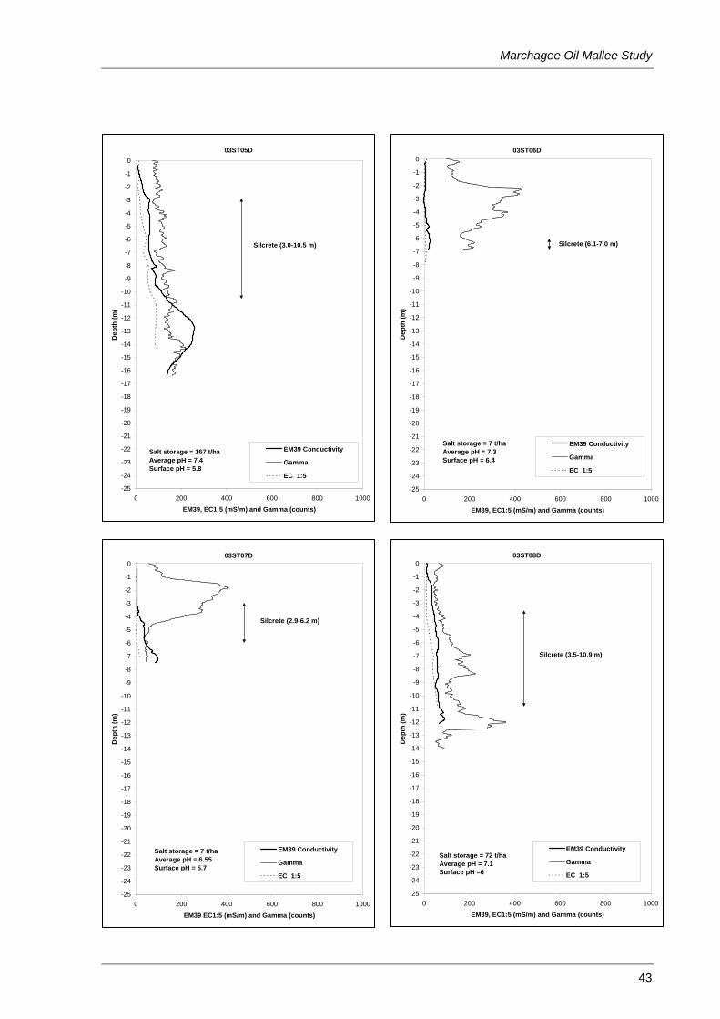
Marchagee Oil Mallee Study
43
03ST05D
-25
-24
-23
-22
-21
-20
-19
-18
-17
-16
-15
-14
-13
-12
-11
-10
-9
-8
-7
-6
-5
-4
-3
-2
-1
0
0 200 400 600 800 1000
EM39, EC1:5 (mS/m) and Gamma (counts)
Dep
th (m
)
EM39 Conductivity
Gamma
EC 1:5
Salt storage = 167 t/haAverage pH = 7.4Surface pH = 5.8
Silcrete (3.0-10.5 m)
03ST06D
-25
-24
-23
-22
-21
-20
-19
-18
-17
-16
-15
-14
-13
-12
-11
-10
-9
-8
-7
-6
-5
-4
-3
-2
-1
0
0 200 400 600 800 1000
EM39, EC1:5 (mS/m) and Gamma (counts)
Dep
th (m
)
EM39 Conductivity
Gamma
EC 1:5
Salt storage = 7 t/haAverage pH = 7.3Surface pH = 6.4
Silcrete (6.1-7.0 m)
03ST07D
-25
-24
-23
-22
-21
-20
-19
-18
-17
-16
-15
-14
-13
-12
-11
-10
-9
-8
-7
-6
-5
-4
-3
-2
-1
0
0 200 400 600 800 1000
EM39 EC1:5 (mS/m) and Gamma (counts)
Dep
th (m
)
EM39 Conductivity
Gamma
EC 1:5
Salt storage = 7 t/haAverage pH = 6.55Surface pH = 5.7
Silcrete (2.9-6.2 m)
03ST08D
-25
-24
-23
-22
-21
-20
-19
-18
-17
-16
-15
-14
-13
-12
-11
-10
-9
-8
-7
-6
-5
-4
-3
-2
-1
0
0 200 400 600 800 1000
EM39, EC1:5 (mS/m) and Gamma (counts)
Dep
th (m
)
EM39 Conductivity
Gamma
EC 1:5
Salt storage = 72 t/haAverage pH = 7.1Surface pH =6
Silcrete (3.5-10.9 m)

June 2009
44
03ST09D
-25
-24
-23
-22
-21
-20
-19
-18
-17
-16
-15
-14
-13
-12
-11
-10
-9
-8
-7
-6
-5
-4
-3
-2
-1
0
0 200 400 600 800 1000
EM39, EC1:5 (mS/m) and Gamma (counts)
Dep
th (m
)
EM39 Conductivity
Gamma
EC 1:5
Salt storage = 133 t/haAverage pH = 6.8Surface pH = 5.2
Silcrete (3.1 - 8.5 m)
03ST10D
-25
-24
-23
-22
-21
-20
-19
-18
-17
-16
-15
-14
-13
-12
-11
-10
-9
-8
-7
-6
-5
-4
-3
-2
-1
0
0 200 400 600 800 1000
EM39, EC1:5 (mS/m) and Gamma (counts)
Dep
th (m
)
EM39 Conductivity
Gamma
EC 1:5
Salt storage = 35 t/haAverage pH = 7.8Surface pH = 6.8
03ST11D
-25
-24
-23
-22
-21
-20
-19
-18
-17
-16
-15
-14
-13
-12
-11
-10
-9
-8
-7
-6
-5
-4
-3
-2
-1
0
0 200 400 600 800 1000
EM39, EC1:5 (mS/m) and Gamma (counts)
Dep
th (m
)
EM39 Conductivity
Gamma
EC 1:5
Salt storage = 117 t/haAverage pH = 7.2Surface pH = 6.5
Silcrete (6.9-13.5 m)

Marchagee Oil Mallee Study
45
6.3 Bulk soil sample analyses
Bore name Depth (m)
EC 1:5 (mS/m)
pH 1:5 (Water)
Cl % (Titration #)
Average EM39 (Quadrature, mS/m)
03ST01D Surface 14 5.7 0.004 03ST01D -1 6 6.4 0.002 8 03ST01D -2 17 5.5 0.018 -2 03ST01D -3 21 6.9 0.024 8 03ST01D -4 32 6.9 0.040 26 03ST01D -5 23 7.3 0.028 35 03ST01D -6 30 7.3 0.037 57 03ST01D -7 45 6.7 0.056 76 03ST01D -8 46 6.1 0.057 89 03ST01D -9 56 5.6 0.074 104 03ST01D -10 40 5.4 0.057 102 03ST01D -11 32 5.5 0.048 109 03ST01D -12 25 5.7 0.038 83 03ST01D -13 26 5.0 0.032 81 03ST01D -14 31 4.8 0.039 87 03ST01D -15 23 5.0 0.038 96 03ST01D -16 29 4.6 0.040 114 03ST01D -17 29 4.8 0.036 118 03ST01D -18 35 5.2 0.052 119 03ST01D -19 30 5.3 0.040 120 03ST01D -20 36 5.6 0.045 120 03ST01D -23 48 5.6 0.067 114 03ST02D Surface 3 5.5 0.002 03ST02D -1 4 5.4 0.002 -13 03ST02D -2 3 5.2 0.001 -12 03ST02D -3 4 6.0 0.001 -10 03ST02D -4 5 6.8 0.001 -5 03ST02D -5 8 6.8 0.001 15 03ST02D -6 3 7.2 0.002 31 03ST02D -7 4 7.1 0.002 31 03ST02D -8 5 7.1 0.004 47 03ST02D -9 7 7.0 0.008 42 03ST02D -10 7 7.0 0.009 42 03ST02D -11 8 7.0 0.009 43 03ST02D -12 8 7.0 0.009 46 03ST02D -13 12 6.9 0.016 50 03ST02D -14 10 7.1 0.011 51 03ST02D -15 8 7.3 0.009 51 03ST02D -16 6 7.4 0.007 50 03ST03D Surface 2 5.8 0.001 03ST03D -1 3 6.8 0.002 3 03ST03D -2 4 6.8 0.002 4 03ST03D -3 4 7.0 0.002 6 03ST03D -4 3 7.3 0.003 13 03ST03D -5 4 7.3 0.003 29 03ST03D -6 3 7.3 0.002 32 03ST03D -7 4 7.2 0.002 22 03ST03D -8 6 7.1 0.006 23 03ST03D -9 10 7.1 0.009 28 03ST03D -10 10 7.0 0.010 52 03ST03D -11 8 7.2 0.008 64 03ST04D Surface 2 5.6 0.001 03ST04D -1 1 6.5 0.000 3 03ST04D -2 3 6.6 0.002 4 03ST04D -3 8 7.1 0.007 5 03ST04D -4 8 7.6 0.004 15 03ST04D -5 7 7.8 0.006 34 03ST04D -6 8 7.6 0.008 37 03ST04D -7 7 7.5 0.007 45
54

June 2009
46
Bore name Depth
(m) EC 1:5 (mS/m)
pH 1:5 (Water)
Cl % (Titration #)
Average EM39 (Quadrature, mS/m)
03ST05D Surface 12 5.8 0.013 03ST05D -1 16 6.3 0.019 9 03ST05D -2 9 6.9 0.009 22 03ST05D -3 18 7.6 0.023 41 03ST05D -4 21 7.8 0.024 57 03ST05D -5 32 7.8 0.037 61 03ST05D -6 45 7.7 0.052 59 03ST05D -7 34 7.9 0.038 57 03ST05D -8 55 7.7 0.071 70 03ST05D -9 52 7.8 0.055 83 03ST05D -10 63 7.6 0.071 94 03ST05D -11 88 7.4 0.096 135 03ST05D -14 84 7.5 0.099 250 03ST06D Surface 9 6.4 0.006 03ST06D -1 2 7.2 0.000 4 03ST06D -2 2 7.3 0.000 4 03ST06D -3 2 6.7 0.001 2 03ST06D -4 3 7.4 0.001 2 03ST06D -5 4 7.6 0.002 9 03ST06D -6 5 7.9 0.004 18 03ST06D -7 8 8.0 0.007 03ST06D -8 6 7.6 0.004 03ST07D Surface 4 5.7 0.002 03ST07D -1 2 6.7 0.000 5 03ST07D -2 4 6.3 0.001 4 03ST07D -3 3 6.4 0.001 5 03ST07D -4 5 6.8 0.001 9 03ST07D -5 2 7.1 0.001 29 03ST07D -6 5 6.9 0.004 37 03ST07D -7 18 6.5 0.015 65 03ST08D Surface 10 6.0 0.010 03ST08D -1 11 7.2 0.010 12 03ST08D -2 8 6.8 0.006 27 03ST08D -3 10 7.1 0.009 33 03ST08D -4 10 7.1 0.008 40 03ST08D -5 20 7.6 0.022 49 03ST08D -6 28 7.5 0.033 57 03ST08D -7 41 7.4 0.052 59 03ST08D -8 38 7.2 0.040 58 03ST08D -11 60 7.3 0.074 65 03ST09D Surface 4 5.2 0.001 03ST09D -1 3 6.6 0.001 -12 03ST09D -2 6 6.4 0.004 -11 03ST09D -3 6 7.1 0.004 -7 03ST09D -4 10 6.8 0.006 9 03ST09D -5 14 6.8 0.017 16 03ST09D -6 18 6.6 0.025 18 03ST09D -7 19 6.7 0.025 20 03ST09D -8 30 6.8 0.036 33 03ST09D -9 22 6.8 0.029 48 03ST09D -10 16 6.8 0.018 51 03ST09D -11 14 6.8 0.015 48 03ST09D -12 9 7.1 0.010 38 03ST09D -13 13 7.3 0.014 38 03ST09D -14 30 7.3 0.038 46 03ST09D -17 30 7.4 0.037 54 03ST10D Surface 25 6.8 0.033 03ST10D -1 18 8.0 0.018 03ST10D -2 23 8.4 0.024 106 03ST10D -3 24 8.2 0.025 109 03ST10D -4 26 7.6 0.028 96
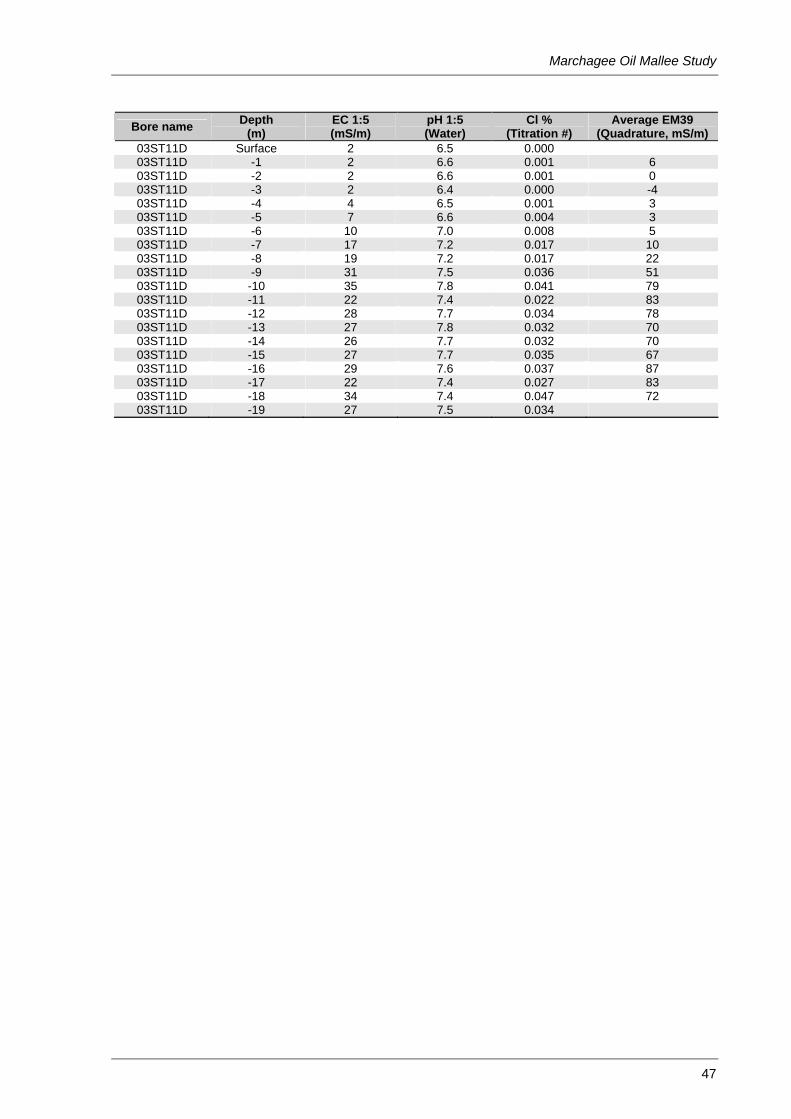
Marchagee Oil Mallee Study
47
Bore name Depth
(m) EC 1:5 (mS/m)
pH 1:5 (Water)
Cl % (Titration #)
Average EM39 (Quadrature, mS/m)
03ST11D Surface 2 6.5 0.000 03ST11D -1 2 6.6 0.001 6 03ST11D -2 2 6.6 0.001 0 03ST11D -3 2 6.4 0.000 -4 03ST11D -4 4 6.5 0.001 3 03ST11D -5 7 6.6 0.004 3 03ST11D -6 10 7.0 0.008 5 03ST11D -7 17 7.2 0.017 10 03ST11D -8 19 7.2 0.017 22 03ST11D -9 31 7.5 0.036 51 03ST11D -10 35 7.8 0.041 79 03ST11D -11 22 7.4 0.022 83 03ST11D -12 28 7.7 0.034 78 03ST11D -13 27 7.8 0.032 70 03ST11D -14 26 7.7 0.032 70 03ST11D -15 27 7.7 0.035 67 03ST11D -16 29 7.6 0.037 87 03ST11D -17 22 7.4 0.027 83 03ST11D -18 34 7.4 0.047 72 03ST11D -19 27 7.5 0.034

June 2009
48
6.4 Comparison of EC1:5 and EM39
y = 1.9831x + 5.3735R2 = 0.712
0
20
40
60
80
100
120
140
160
180
200
0 10 20 30 40 50 60 70 80
EC1:5 (mS/m)
Ave
rage
d Q
uadr
atur
e (m
S/m
)