march 13, 2006 addendum to
TRANSCRIPT

March 13, 2006 Addendum
to
A University Program of Accelerator and Detector Research for the International Linear Collider
(vol. IV)
FY 2006 – FY 2007
University Consortium for Linear Collider R&D Linear Collider Research and Development Working
Group
2006
G.D. Gollin, editor

Table of Contents (February 11, 2006)
Revised author list (9 pages)................................................................................................3 2.45: Real Time Simulator for ILC RF and CryoModules (Nigel Lockyer: new proposal submitted too late for inclusion in the January 18 release of A University Program…; 8 pages) .................................................................................................................................12 6.9: Development of Particle-Flow Algorithms and Simulation Software for the ILC Detector(s) (Dhiman Chakraborty: corrected version of renewal proposal; 15 pages) .....20 6.19: Summary of visit to IHEP, Beijing, and discussions on Princeton-IHEP collaboration for ILC R&D (Changguo Lu, Princeton University, supplemental material to accompany project 6.19; 3 pages)..................................................................................35 6.21: Modular DAQ Development for the ILC SiD (Satish Dhawan; new proposal, mistakenly labeled 4.3 in the January 18 release of A University Program…; 6 pages) ...38 Revised participation data tables .......................................................................................44
Additional corrections (March 13, 2006)
The following projects’ submissions are progress reports. They had been mistakenly described as new proposals when I had assembled the proposal document in January. 2.47: Magnetic Investigation of High Purity Niobium for Superconducting RF Cavities (progress report) 2.48: 3D Atom Probe Microscopy on Niobium for SRF Cavities (progress report) 2.52: Investigation of Plasma Etching for Superconducting RF Cavities Surface Preparation (progress report)

University Consortium for Linear Collider R&D and
Linear Collider Research and Development Working Group
U.S. National Laboratories and Industries
John M. Butler, Meenakshi Narain Boston University
Dept. of Physics, 590 Commonwealth Avenue, Boston, MA 02215 (1)[2]
Richard Partridge Brown University
Dept. of Physics, Box 1843, Providence, RI 02912 (2)[1]
J. Albert, D. Hitlin, and F. Porter California Institute of Technology
Physics Department 103-33, Pasadena, CA 91125 (3)[3]
Marco Battaglia and Yury Kolomensky University of California, Berkeley,
Dept. of Physics, Berkeley, CA 94720 (4)[2]
R. Lander, B. Holbrook, and Mani Tripathi, University of California, Davis
Dept. of Physics, 1 Shields Avenue, Davis, CA 95616 (5)[3]
David B. Cline, Yasuo Fukui, Feng Zhou University of California, Los Angeles
Dept. of Physics and Astronomy, 405 Hilgard Ave., Los Angeles, CA 90095-1547 (6)[3]
H. P. Paar University of California, San Diego
Department of Physics, 9500 Gilman Drive, La Jolla, CA 92093 (7)[1]
Bruce Schumm, Ned Spencer, Alex Grillo, Jurgen Kroseberg, K. Conley, G. Horn, F. Martinez-McKinney, and M. Wilder University of California, Santa Cruz
Dept. of Physics, Inst. for Particle Physics, Nat Sci 2, Santa Cruz, CA 95064 (8)[8]
Mark Oreglia University of Chicago
The Enrico Fermi Institute, 5640 South Ellis Avenue, Chicago, IL, 60637 (9)[1]<24>

S. Moll, Uriel Nauenberg, Matthew Phillips, Joseph Proulx, E. Smith, P. Steinbrecher, Stephen R. Wagner, F. Blanc, Shenjian Chen, R. Clancy, Keith Drake, Eric Erdos, C.
Geraci, J. Gill, Jason Gray, Keith Miller, and Jinlong Zhang University of Colorado
Dept. of Physics, Boulder, CO 80309-0390 (10)[17]
David Warner, Robert Wilson Colorado State University
Dept. of Physics, Fort Collins, CO 80523-1875 (11)[2] J. Alexander, F. Barb, A. C. Center, G. F. Dugan, R. Ehrlich, R. S. Galik, L. Gibbons, L.
N. Hand, R. Helms, R. Meller, A. Mikhailichenko, C. K. Ober, M. Palmer, D. P. Peterson, D. Rubin, D. Sagan, L. Schachter, J. Smith, M. Tigner, J. Urban, and
R. B. Van Dover Cornell University
Laboratory for Elementary Particle Physics Ithaca, NY 14853-2501 (12)[21]
Dave Winn, V. Podrasky, C. Sanzeni
Fairfield University Dept. of Physics, Fairfield, CT, 06430 (13)[3]
G. Varner, M.Barbero, T.Browder, J.Kennedy, E.Martin, S.Olsen, M.Rosen, L.Ruckman,
K.Trabelsi, K.Uchida, Q.Yang University of Hawaii at Manoa
Dept. of Physics and Astronomy, 2505 Correa Road, Honolulu, Hawai'i 96822 (14)[11] Guy Bresler, Joseph Calvey, Jason Chang, Michael Davidsaver, Keri Dixon, G.D. Gollin,
M.J. Haney, Justin Phillips
University of Illinois at Urbana-Champaign Dept. of Physics, 1110 W. Green, Urbana, IL, 61801 (15)[8]
Robert Abrams, and Richard J. Van Kooten
Indiana University Dept. of Physics, Swain West 117, Bloomington, IN, 47405 (16)[2]
U. Akgun, E. Albayrak, Matthew J. Charles, F. Duru, Usha Mallik, J. P. Merlo, A.
Mestvirisvili, N. Meyer, M. Miller, E. Norbeck, Yasar Onel, I. Schmidt, M. Smalley, and J. Wetzel
University of Iowa Dept. of Physics and Astronomy, Van Allen Hall, Iowa City, IA, 52242 (17)[14]
Walter Anderson, John Hauptman, Sam Ose, J. Lamsa, S. Lee, Y. Roh, and M. Stemper
Iowa State University Dept. of Physics and Astronomy, Ames, IA, 50011 (18)[7]<86>

Jonathan van Eenwyk, Graham Wilson, M. Ambroselli, E. Benavidez, C. Hensel, and M. Treaster
University of Kansas Dept. of Physics and Astronomy, Lawrence, Kansas 66045 (19)[6]
Tim Bolton, Dima Onoprienko, Eckhard von Toerne
Kansas State University Dept. of Physics, Manhattan, KS 66506-2601 (20)[3]
E. Schuster
Lehigh University Packard Laboratory, 19 Memorial Drive West, Bethlehem, PA 18015-3085 (21)[1]
Lee Sawyer, Z. D. Greenwood, Tony Forest
Louisiana Technical University Center for Applied Physics Studies
W Arizona Ave., Ruston, Louisiana 71272-0046 (22)[3]
S. Bernal, D. Feldman, R. A. Kishek, and M. Walter University of Maryland
College Park, MD 20742-3511 (23)[4]
Chiping Chen Massachusetts Institute of Technology
Dept. of Physics, MIT 44-120, Cambridge, MA, 02139 (24)[1]
S. Nyberg, K. Riles, H. Yang University of Michigan
Dept. of Physics, Univ. of Michigan, Ann Arbor, MI 48109 (25)[3] T. Bieler, J. Bierwagen, S. Bricker, C. Compton, P. Glennon, T. L. Grimm, W. Hartung, D. Harvell, H. Jiang, M. Johnson, F. Marti, M. Meidlinger, J. Popielarski, L. Saxton, and
R. C. York Michigan State University
Department of Physics & Astronomy, East Lansing, MI 48824-2320 (26)[15]
M. Ehrilichman, R. Poling, and A. Smith University of Minnesota
Dept. of Physics 116 Church Street S.E., Minneapolis, MN 55455 (27)[3] James Ellison1, Gabriele Bassi1, Klaus Heinemann1, Bernd Bassalleck2, Doug Fields2, M.
Gold2, J. Matthews2, D. Loomba2, and M. Hoeferkamp2
University of New Mexico 1Dept. of Mathematics and Statistics; 2Dept. of Physics, Albuquerque, NM 87131
(28)[9]<48>
Jesse Ernst State University of New York at Albany
Dept. of Physics, 1400 Washington Ave., Albany, NY 12222 (29)[1]
S. Mtingwa North Carolina A&T State University
Dept. of Physics, 101 Marteena Hall, Greensboro, NC 27411 (30)[1]
Gerald Blazey, Court Bohn, Dhiman Chakraborty, Alexandre Dychkant, K. Francis, David Hedin, J.G. Lima, R. McIntosh, D. Mihalcea, V. Rykalin, N. Vinogradov, and
V. Zutshi Northern Illinois University
Dept. of Physics and Northern Illinois Center for Accelerator and Detector Development, DeKalb, IL, 60115 (31)[12]
D. N. Seidman, K. E. Yoon
Northwestern University Dept. of Physics and Astronomy, Evanston, IL, 60208-3112 (32)[2]
Michael Hildreth, M. McKenna, Mitchell Wayne
University of Notre Dame Dept. of Physics, 225 Nieuwland Science Hall, Notre Dame, IN, 46556-5670 (33)[3]
Daniel Snowden-Ifft, Occidental College
Los Angeles, CA 90041 (34)[1]
K. K. Gan , Mark Johnson, Richard Kass, J. Moore, Chuck Rush Ohio State University
Dept. of Physics, 174 W 18th Ave, Columbus, OH, 43210 (35)[5]
Leposava Vušković, S. Popović, M. Rasković Old Dominion University
Department of Physics, 4600 Elkhorn Ave., Norfolk, VA 23529-0116 (36)[3]
J. Brau, Raymond Frey, I. Igonkina, N. Sinev, D. Strom, Eric Torrence University of Oregon
Dept. of Physics, 1371 E 13th Avenue, Eugene, OR 97403 (37)[6]
AnnaGrassellino, JustinKeung, Nigel Lockyer, MitchNewcomer University of Pennsylvania
Dept. of Physics and Astronomy, 209 South 33rd St., Philadelphia, PA 19104-6396 (38)[4]

J.Mueller University of Pittsburg
Department of Physics and Astronomy, 3941 O'Hara Street, Pittsburg, PA 15260, USA (39)[1]
Changguo Lu, Kirk T. McDonald, P. D. Meyers, J. D. Olsen, W. Sands, A. J. S. Smith, J.
Biesiada Princeton University
Dept. of Physics, Princeton, NJ 08544 (40)[7]<42>
Kirk Arndt, G. Bolla, Alvin Laasanena, Abe Spinelli Virgil Barnes, Daniela Bortoletto, Ian Shipsey, and P. Merkel
Purdue University Dept. of Physics, 1396 Physics Department, West Lafayette, IN, 47907 (41)[8]
William Bugg, Steve Berridge, Yury Efremenko, Thomas Handler, Stefan Spanier, Yuri
Kamyshkov University of Tennessee
Dept. of Physics, Univ. of Tennessee, Knoxville, TN, 37996-1200 (42)[6]
Andrew Brandt, Kaushik De, Jia Li, Mark Sosebee, Andy White, Jae Yu University of Texas at Arlington
Dept. of Physics, Box 19059, High Energy Physics, UTA, Arlington, TX, 76019 (43)[6]
Nural Akchurin, H. Kim, R. Wigmans Texas Technical University
Dept. of Physics, MS 1051, Lubbock, Texas 79409 (44)[3]
William P. Oliver Tufts University
Dept. of Physics and Astronomy, Medford, MA, 02155 (45)[1]
B. S. Shivaram University of Virginia
Dept. Of Physics, Charlottesville, VA 22904 (46)[1]
S. G. Corcoran Virginia Tech
Materials Science & Engineering, Collegiate Square, Suite 302, Blacksburg, VA 24060 (47)[1]
C. Daly, H. J. Lubatti, M. Tuttle, Tianchi Zhao
University of Washington Department of Physics, Box 351560, Seattle, WA 98195-1560 (48)[4]

Giovanni Bonvicini, David Cinabro, Mikhail Dubrovin, Alfredo Gutierrez, Paul Karchin
Wayne State University Dept. of Physics, 666 W. Hancock, Detroit, MI, 48202 (49)[5]
M. J. Kelley
College of William & Mary Department of Physics, P.O. Box 8795Williamsburg, VA 23187-8795 (50)[1]<36>
2D. Larbalestier, 2P. Lee, A. 2Polyanskii, 1Richard Prepost, 2A. Squitieri, 2A. Gurevich University of Wisconsin-Madison
1Dept. of Physics, 1150 University Ave.; 2Applied Superconductivity Center, 1500 Engineering Drv Madison, WI, 53706 (51)[6]
C. Baltay1, S. Dhawan, W. Emmet1, J. Hirshfield2, M. A. LaPointe, H. Neal1, D.
Rabinowitz1
Yale University Dept. of Physics, Sloane Physics Lab1, Beam Physics Laboratory2
217 Prospect Street, PO Box 208120, New Haven, CT 06520-8120 (52)[7]
U.S. National Laboratories and Industries
S. Vasile aPeak Inc., 63 Albert Rd., Newton, MA 02466-1302 (1)[10]
Gary Drake, Wei Gai, V. Guzrino, Y. Li, B. Musgrave, John Power, José Repond, Dave Underwood, H. Weerts, Barry Wicklund, Lei Xia, S. Magill, J. Norem, Steve Kuhlman,
Argonne National Laboratory 9700 South Cass Avenue, Argonne, IL 60439 (2)[14]
V. Radeka
Brookhaven National Laboratory Upton, NY 11973-5000 (3)[1]
P. Bauer, L. Bellantoni, C. Boffo, A. Bross, B. Choudhary, Bill Cooper, Marcel
Demarteau, D. Denisov, H. Eugene Fisk, James Hoff, Kurt Krempetz, Abderrezak Mekkaoui, Caroline Milstene, Sergei Nagaitsev, Adam Para, Oleg Prokofiev, M. Wendt,
R. Yarema Fermi National Accelerator Laboratory
PO Box 500, Batavia, IL, 60510 (4)[17]

A. Wolski, D. N. Brown, D. Contarato, L. Greiner, B. Hooberman, J. Kadyk, Y. M. Venturini
Lawence Berkeley National Laboratory Berkeley, CA 94720 (5)[7]
V. Yakovlev
Omega P, Inc. 199 Whitney Ave., New Haven, CT. (6)[1]
Ray Arnold, Paul Bolton, G. Bowden, M. Breidenbach, S. Dong, A. Fisher, D. Freytag, Joe Frisch, N. Graf, G. Haller, R. Herbst, A. Johnson, N. Kurita, Thomas Markiewicz,
Ken Moffeit, M. Pivi, B. Ratcliff, Marc Ross, Steve Smith, Peter Tenenbaum, L. Wang, Robert Warnock, Michael Woods
Stanford Linear Accelerator Center 2575 Sand Hill Road, Menlo Park, CA, 94025 (7)[23]
A.-M. Valente, L. Phillips, C. E. Reece
Thomas Jefferson National Accelerator Facility 12000 Jefferson Avenue, Newport News, VA 23606 (8)[3]
Foreign Collaborating Institutions
Erhan Gülmez Bogazici University
Dept. of Physics, Istanbul, Turkey (1)[1]
E. V. Kozyrev Budker Inst. of Nuclear Physics
Acad. Lavrentiev prospect 11, 630090 Novosibirsk, Russia (2)[1]
David Ward, Mark Thomson Cambridge University
Cavendish Laboratory, Madingley Road, Cambridge CB3 OHE, United Kingdom (3)[2]
Changhie Han Changwon National University
9 Sarim-dong, Changwon, Kyongnam, 641-773, Korea (4)[1]
Gulsen Onengut Cukurova University
Dept. of Physics, Adana, Turkey (5)[1]
A. Clarke Daresbury Laboratory Warrington, UK (6)[1]

W. Decking, F. Sefkow DESY
Notkestr. 85, 22607 Hamburg, Germany (7)[2]
Robert Rossmanith Forschungszentrum Karlsruhe, Germany (8)[1]
Alexander S. Aryshev, M.Hazumi, Pavel V. Karataev, Toshiya Muto, Makoto Tobiyama,
T.Tsuboyama, Junji Urakawa KEK, High Energy Accelerator Research Organization
Tsukuba Science City, Japan (9)[7]
Ramazan Sever METU
Dept. of Physics, Ankara, Turkey (10)[1]
A.Boze, H. Palka H. Niewoniczanski Institute of Nuclear Physics
Polish Academy of Sciences, Ul. Radzikowskiego 152, 31-342 Krakow, Poland (11)[2]
Vladimir Atramentov NIPT
Ukraine (12)[1]
S.Stanič Nova Gorica Polytechnic
Vipavska 13, 5000 Nova Gorica, Slovenia (13)[1]
N. Delerue Oxford
United Kingdom (14)[1]
J.Y. Huang PAL POSTECH
Korea (15)[1]
G. Introzzi University of Pavia
Italy (16)[1]
C. Damerell Rutherford Appleton Laboratory
Chilton, Didcot Oxon, UK
OX11 0QX (17)[1]

M. Daanilov Inst of Theoretical and Experimental Physics
Bolshaya Cheremushkinskaya, 25, 117218 Moscow, Russia (18)[1]
Hitoshi Yamamoto Tohoku University
Japan (19)[1]
H.Aihara University of Tokyo
Dept. of Physics, 7-3-1 Hongo Bunkyo-ku, Tokyo 113-0033, Japan (20)[2]
Ryosuke Hamatsu, Pavel V. Karataev Tokyo Metropolitan University
Dept. of Physics, Tokyo, Japan (21)[2]
Alexander P. Potylitsyn, Gennady A. Naumenko, Alexander S. Aryshev, A. Sharafutdinov
Tomsk Polytechnic University Russia (22)[4]
Aldo Penzo
University of Trieste, INFN-Trieste Dept. of Physics, Trieste Italy (23)[1]
Li Jin, Yulan Li, Yongfang Lai, Yue Qian
Tsinghua University China (24)[4]
David Miller, Alex Ljapine
University College London, U.K. (25)[2]
PROJECT DESCRIPTION
Project Name
Real Time Simulator for ILC RF and CryoModules
Personnel and Institution(s) requesting funding
Nigel Lockyer (Professor) University of PennsylvaniaAnna Grassellino (1st year graduate student) University of PennsylvaniaJustin Keung (1st year graduate student) University of PennsylvaniaMitch Newcomer (instrumentation physicist) University of Pennsylvania
Collaborators
Sergei Nagaitsev Fermilab
Project Leader
Nigel [email protected] 715 3120
Project Overview
We propose to develop a detailed real time simulator and simulation package to model thebehavior of an ILC RF unit. An ILC unit is presently defined to be 24 cavities distributedin three cryomodules with RF power. The high operational overhead and potential risk ofdamage during tests of control hardware makes it important to develop a realistic test bedindependent of the cryomodules and associated RF hardware. We are using the simulationpackage to understand and redefine in some cases, the specifications for the RF and LLRFsystem for the ILC BCD. This work has begun and we report some preliminary results later.We plan to move the simulation package into a hardware implementation, such that we canhave a real time simulator (RTS) of the RF unit and cryomodules. Based on discussions withRF and LLRF colleagues at Fermilab, Ruben Carcagno, Brian Chase, Gustavo Cancelo, andSergei Nagaitsev, we will implement the RTS package using a common simulation toolsetbased on the MATLAB symbolic simulator, Simulink, and a commercial digital communica-tions board. We have had discussions with colleagues at Pisa (Fabrizio Scura) and DESY(Elmar Vogel and Stefan Simrock) and are exploring a possible collaborations with them.This project is aimed initially at the Fermilab ILC beam test facility, but will also be of useto RF and cryomodule testing facilities at DESY and KEK as well. The RTS will be used fortesting and commissioning of the Low Level RF control, exception handling, and possibly asa noiseless behavioral reference for each cryomodule during operation.
Broader Impact
This proposal will train accelerator physicists. There are already two graduate students (oneof whom is a woman) involved and interested in careers in accelerator physics. There are twoundergraduates working on the project for the summer.
1
Results of Prior Research
The Penn group has been developing a SRF cavity simulator for about six months. Inaddition, we have been interacting with the international LLRF community for over one yearand we have participated in “LLRF week” at DESY in the TTF test beam.
Effects included in the present version of the simulation are:
1. cavity detuning
2. Q-drop and Q-slope
3. phase noise (phase jitter)
4. beam loading
5. feedback gain and loop delay (gain bandwidth product)
6. electronics and cable feedback delay
7. klystron power saturation (CPI)
8. modulator ripple (MARX and Fermilab modulator power shapes)
A detailed description of the simulation exists and is available at Justin Keung’s web page(http://einstein.hep.upenn.edu/∼keungj). Instructions are provided on this web site for run-ning the simulator and results on each of several study topics are presented in a short noteformat. Notes available include: Full Design Note for Cavity Simulation, Effects of the Q ofCavity on Amplitude and Phase Noise, Effects of Noise versus Varying Feedback Gain, andEffects of the LLRF Control Latency.
The cavity model has been implemented in “C” code and is based on the observation thatto first order a cavity behaves like an elementary R-L-C network as presented in the 1998Thesis of Schilcher [1]. As with any R-L-C circuit, the voltage and current behaviour can bemodeled by a set of differential equations. Lorentz force de-tuning [2] is added as a refinementof the cavity behavior and the non linear effects of the klystron drive were added as first orderimprovements on the model. We have used it to look at the effects of loop delay, clock jitter,and modulator ripple on feedback for the LLRF control. Feed Forward algorithms are is nowbeing examined.
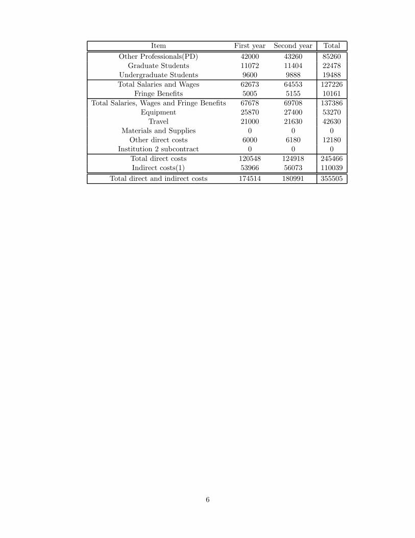
As an example of a test run of the cavity simulator, we show results for amplitude and phaseresponse of the Tesla cavity. Figure 1 shows two plots that indicate the accelerating gradientfilling time, flat top, and decay, the effects of Lorentz Force detuning and the varying Q ofthe cavity and the beam loading. The changing phase, which agrees well with TTF test beambehavior is shown in the second plot.
Facilities, Equipment and Other Resources
The Penn High Energy Physics group is well supported by DOE HEP. It is one of the strongeruniversity instrumentation groups in the country. The group designs custom integrated cir-cuits and has provided integrated circuits to many groups around the world as a by productof our own program, at cost. The ASDQ chip, used for drift chamber readout, is one ex-ample. It is the frontend readout chip for the CDF Central Outer Tracker(30,240 channels),that was Lockyer and Newcomer’s main responsibility to the CDF upgrade. We design andbuild complex circuit boards, program FPGAs, and design numerous electronic systems. Thegroup has just finished delivering 375,000 front-end readout channels for the Atlas Transition
2

Radiation Tracker. Penn has excellent computing available and substantial lab space for theHEP group.
First year Project Activities and Deliverables
Symbolic Device Blocks
We propose to develop an ILC specific library of symbolic library blocks that model specificphysical objects in the accelerator system: Klystron, Modulator, Cavity, etc. These sym-bolic blocks would employ a ’C’ based representation for software modeling and an ’HDL’based model for hardware response representation. The Block format would allow for 5 basicparts although the HDL model would only be used where a hardware output was directly orindirectly involved.
It has been shown by E. Vogel and W. Hofle [4] that accelerator components can be successfullymodeled using a MATLAB based symbolic representation tool called Simulink. Their workon the CERN SPS beam was able to predict residual transverse oscillations in a stored beambunch due to the extraction of a previous beam bunch. As a result a model for a transversefeedback system was developed and will be used to damp the beam in the SPS ring.
ILC specific Symbolic Blocks that we and others develop would be reviewed by institutionswith expertise is the appropriate areas such as (DESY, PISA, Fermilab, SLAC, KEK) and“registered” when consensus is reached on their fidelity. In this way both baseline and pro-posed hardware could be modeled. LLRF control algorithms could be tested and devicespecific specifications could be proposed before the hardware was available for integrationinto a beamline.
Real Time Simulator
We propose to extend the software representations of the cavity and high level RF systeminto a Hardware based Real Time Simulator (RTS). We have identified commercially availablehigh speed hardware (LyrTech VHS-ADC) with multiple A/D and D/A’s and a very largeFPGA on a single board. The board has a latency for a simple R/W cycle of less than 200ns from A/D input thru the FPGA and out to a D/A. With this board, a real time responseappears to be within reach. We would develop the RTS in steps:
1. A single cavity model with IF Vector Modulator inputs (driven by the LLRF control)and three IF output mimicking the downconverted field pickup signals. This modelwould immediately allow for several interesting tests to be performed with any LLRFcontroller. For example: Noise can be added to the IF output to understand how tocope with noise in the down convertor and klystron performance characteristics such assaturation and power variation due to modulator ripple can be added.
2. A multi-cavity module can be modeled by phasing the RF from each of the cavitiesby the appropriate phase. Since the LyrTech board has only 8 D/A outputs a seconddaughter board with up to 16 D/A’s would be required if more than one output percavity is required.
3. The ultimate goal would be to model a full ILC RF unit consisting of three 8 cellcavities powered by a single klystron and modulator. The phasing of the output IFbetween boards will be critical. The LyrTech 400MHz front panel data port will allowfast updating to multiple boards.
3

At any stage additional quality monitor outputs may be added. Beam quality monitors,modulator ripple monitor, microphonics monitors etc. The bandwidth and latency of theseinputs would play an important role in determining how they were included in the system.
The RTS engine, LyrTech VHS-ADC Board
The engine of the RTS is the LyrTech VHS-ADC Board (see appendix 1 for a more completedescription). The VHS-ADC board has 8 channels of D/A that can operate at 125 MSPS and8 channels of A/D that can be added via daughter board that can operate up to 105 MSPS.These speeds should be high enough to allow for an IF frequency of up to 52.5 MHz. Outputwaveforms will be driven by an Xilinx Virtex II - 6000 with 6 million gates. An internal orexternal clock can be used to drive the D/A, A/D and FPGA clocked operations. The boardincludes a front panel Data Port with up to 400 MBytes per second data transfer rate to keepother boards updated. In addition, very fast I/O can be performed by a General PurposeI/O output driven directly by the Virtex II. It can be programmed to have up to 6 LVDSpairs, each operating at 800Mbits/sec. The VHS-ADC will require a c-PCI crate and PCinterface. We will also need low and high level firmware (MATLAB/SIMULINK) drivers andsoftware support from LyrTech. As we move from a single cavity simulation to a full ILCRF unit with one klystron and three cryo-modules, we will need additional D/A outputs. Asingle 4 slot crate c-PCI bus can support three LyrTech boards, 48 high speed channels ofD/A and A/D that may be split into 8 channel increments. The total number of fast outputsper cavity is not yet fully defined. Assuming that only the RF field probe measurements needto be updated at the IF rate, then the 40 possible D/A outputs in a 4 slot PCI crate shouldsufficient. Additional A/D or D/A outputs would require an expansion crate.
The RTS will make it possible to evaluate RF control elements without attaching to anactual cavity. Effects of heating, beam transmission and noise can be included. The IFoutput signals per cavity provided by the “final” RTS will include RF field from the cavityas well as transmitted and reflected power from the cavity coupler. More signal outputs arepossible as we learn what is valuable to use to keep the LLRF updated. In addition, exceptionhandling may be better understood to help minimize the beam turn on time and reduce downtime due to mistakenly identified fault conditions. RF element failures may be simulated andtheir warning signs may be identified by limiting the non ideal behavior of other parts of thesystem. The synchronous RTS operation of a full ILC RF unit (1 klystron and 3 modules) willallow us to learn the sensitivities of Feedback and Feed Forward algorithms as well as to testrecovery modes from various hardware parametric changes. Clearly there will be significantlearning advantages both planned and unforeseen with a working RTS.
Year One Deliverables
1. implement a multi-cavity simulation and include coherent and incoherent effects
2. include beam amplitude jitter, noise, and temperature effects in the simulation
3. determine the gain and latency needed for the ILC feedback LLRF system.
4. determine the tolerance specification for the modulator power ripple
5. Implement an IF measurement and control based Symbolic Cavity Block, with RF phaseand amplitude inputs coupled in from the Klystron, and three output parameters, inputand reflected power, and RF field from the cavity in Simulink.
6. Purchase Hardware with 1 VHS-ADC board for a Single Cavity Simulator and developa first level Real Time Cavity, Simulator.
4

7. Measure and compare the performance of a real single cavity to the simulation.
The simulation improvements and process for tolerance specifications will be completed byDecember 2006. The RTS will be implemented by summer 2007.
Second year Project Activities and Deliverables
Year Two Deliverables
1. Evolve the single cavity RTS and Symbolic Cavity Blocks to the cryomodule and RFunit level.
2. Purchase additional D/A boards as required with attention to required bandwidth.
3. Test outputs against real cavity signals.
4. Implement RTS with the LLRF control system or systems being designed elsewhere.
We expect that there will be a continuos evolution of the RTS and symbolic block devicerepresentations once cryomodules are available.
Budget justification: University of Pennsylvania
The budget supports one postdoctoral fellow, two summer stipends for graduate students,two undergraduates for the summer, and travel. The travel consists of 2 international tripsper year for Lockyer, Newcomer, and the postdoc. It also includes trips to Fermilab onceevery two months for the postdoc, one every two months for Newcomer, and once every 3months for the graduate students. As a reference Justin Keung, even though taking classes,has traveled to Fermilab twice in the last two months for workshops and presentations. Weexpect this to continue, but cannot continue using CDF funds. His presentations can befound on the WEB page sited above for the simulation. The students are supported by theuniversity during the 9-month school year as teaching assistants. Lockyer travels to Fermilabby combining all trips with CDF activities.
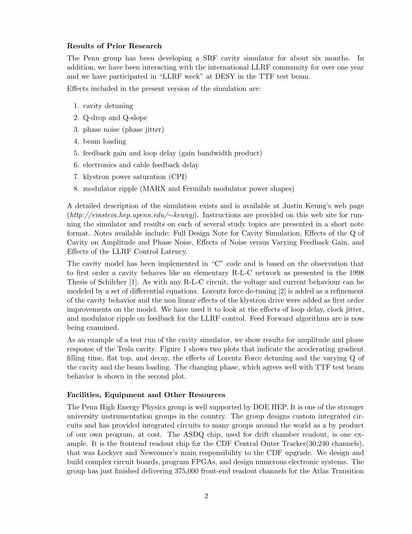
The hardware, described above, consists of a 4-slot c-PCI crate, a processor board and theFPGA board with D/As and A/Ds. In addition, the full suite of simulink software is in-cluded and the quotation includes a significant educational discount of $10,111 applied to thehardware and software. In addition, annual cost for the MATLAB environment software withcomponents for RF control is$2800 per year. We are attempting to get an additional discountthrough the university. Hardware and sofware costs are $25,870 in the first year. In thesecond year, we purchase two additional D/A boards each $11,900, Lyrtech driver softwaremaintenance for $800, MATLAB environment $2800, for a total of $27,400.
The fringe benefits are employee part-time benefits of 5005 year one and 5155 year two.Health insurance for the postdoc is $6000 year one and $6180 year two.
The budget has been prepared in accordance with University of Pennsylvania overhead andemployee benefit rates.
Institution: University of Pennsylvania
5
Item First year Second year Total
Other Professionals(PD) 42000 43260 85260Graduate Students 11072 11404 22478
Undergraduate Students 9600 9888 19488
Total Salaries and Wages 62673 64553 127226Fringe Benefits 5005 5155 10161
Total Salaries, Wages and Fringe Benefits 67678 69708 137386Equipment 25870 27400 53270
Travel 21000 21630 42630Materials and Supplies 0 0 0
Other direct costs 6000 6180 12180Institution 2 subcontract 0 0 0
Total direct costs 120548 124918 245466Indirect costs(1) 53966 56073 110039
Total direct and indirect costs 174514 180991 355505
6

-20.000
-15.000
-10.000
-5.000
0.000
5.000
10.000
15.000
20.000
25.000
30.000
0 0.5 1 1.5 2 2.5 3
Acc
eler
atin
g G
radi
ent (
MV
/m)
RF
+B
eam
Cur
rent
(m
A)
Det
unin
g(x1
00 H
z) Q
of c
avity
(x10
9 )
Time (ms)
Accelerating Gradient, RF+Beam Current and Deturning
|E|Detuning
|I|Q
(a) Amplitude response
-40
-30
-20
-10
0
10
20
0 0.5 1 1.5 2 2.5 3
Eph
ase,
RF
+B
eam
Ipha
se(d
eg)
Det
unin
g(x1
00 H
z)
Time (ms)
Ephase, RF+Beam Iphase and Deturning
EphaseDetuning
(b) Phase response
Figure 1: Cavity response of a real niobium cavity, with initial +300 Hz detuning .
7
References
[1] Thomas Schilcher, Vector Sum Control of Pulsed Accel erating Fields in Lorentz Force De-tuned Superconducting Cavities, Dissertation zur Erlangung des Doktorgrades des Fachbere-ichs Physik der Universitat Hamburg , Hamburg (1998), Ch.3 and Ch.6.
[2] A. Mosnier, Dynamic Measurement of the Lorentz Forces on a MACSE cavity, DESY PrintTESLA 93-09 (1993).
[3] Wenzel Associates Inc., http://www.wenzel.com/documents/noise.html
[4] W. Hoffe, E. Vogel, Simulation of Transient Effects of Beam - Transverse Feedback Interactionwith Application to the Extraction of the CNGS Beam from SPS, CERN-AB-2005-010.
8

STATUS REPORT
Project Name
Development of Particle-Flow Algorithms and Simulation Software for ILC Detector(s)
Personnel and Institution(s) requesting funding
G. Blazey, D. Chakraborty, J. G. Lima, R. McIntosh, V. Zutshi.Northern Illinois Center for Accelerator and Detector Development, Northern Illinois Uni-
versity [1]
Collaborators
S. Magill et al., Argonne National Laboratory,N. Graf et al., Stanford Linear Accelerator Center,C. Milstene et al., Fermi National Accelerator Laboratory,R. Frey et al., University of Oregon,G. Wilson et al., University of Kansas,U. Mallik et al., University of Iowa,The CALICE collaboration.[2]
Project Leader
Dhiman [email protected]
(815)753-8804, (630)840-8569, (630)452-6368
Project Overview
The Northern Illinois University(NIU)/Northern Illinois Center for Accelerator and DetectorDevelopment (NICADD) group is interested in calorimeter R&D for the proposed ILC [1]. Weare developing, in simulation and in prototype, designs for a hadron calorimeter (HCal) opti-mized for jet reconstruction using particle-flow algorithms (a.k.a. “energy-flow algorithms”).Simulation/algorithm development and hardware prototyping are envisaged as the two maincomponents of our efforts. This project addresses the first component while the second is thesubject of a separate project.
An e+e− linear collider is a precision instrument that can elucidate Standard Model (SM)physics near the electroweak energy scale as well as discover new physics processes in thatregime, should they exist. In order to fully realize the potential anticipated from a machineof this type, the detector components must be optimized, sometimes in unprecedented ways,taking full advantage of the most recent developments in technology. One such exampleis the hadron calorimeter which will play a key role in measuring jets from decays of heavyparticles such as vector bosons, the top quark, the Higgs boson(s), etc. In particular, it will beimportant to be able to distinguish in the final state of an e+e− interaction, the presence of a
1
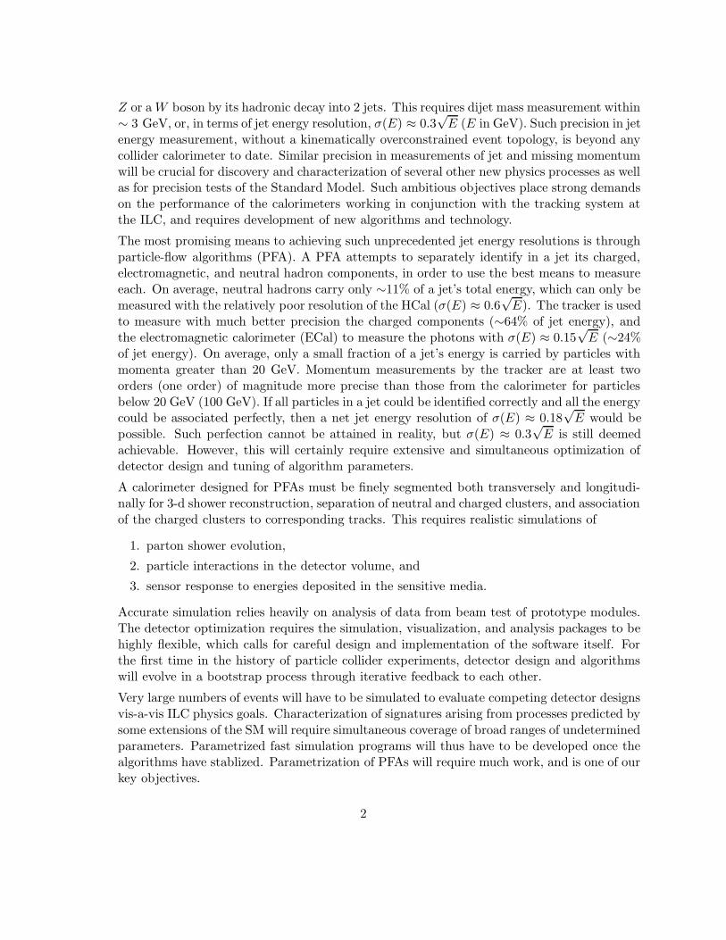
Z or a W boson by its hadronic decay into 2 jets. This requires dijet mass measurement within∼ 3 GeV, or, in terms of jet energy resolution, σ(E) ≈ 0.3
√E (E in GeV). Such precision in jet
energy measurement, without a kinematically overconstrained event topology, is beyond anycollider calorimeter to date. Similar precision in measurements of jet and missing momentumwill be crucial for discovery and characterization of several other new physics processes as wellas for precision tests of the Standard Model. Such ambitious objectives place strong demandson the performance of the calorimeters working in conjunction with the tracking system atthe ILC, and requires development of new algorithms and technology.
The most promising means to achieving such unprecedented jet energy resolutions is throughparticle-flow algorithms (PFA). A PFA attempts to separately identify in a jet its charged,electromagnetic, and neutral hadron components, in order to use the best means to measureeach. On average, neutral hadrons carry only ∼11% of a jet’s total energy, which can only bemeasured with the relatively poor resolution of the HCal (σ(E) ≈ 0.6
√E). The tracker is used
to measure with much better precision the charged components (∼64% of jet energy), andthe electromagnetic calorimeter (ECal) to measure the photons with σ(E) ≈ 0.15
√E (∼24%
of jet energy). On average, only a small fraction of a jet’s energy is carried by particles withmomenta greater than 20 GeV. Momentum measurements by the tracker are at least twoorders (one order) of magnitude more precise than those from the calorimeter for particlesbelow 20 GeV (100 GeV). If all particles in a jet could be identified correctly and all the energycould be associated perfectly, then a net jet energy resolution of σ(E) ≈ 0.18
√E would be
possible. Such perfection cannot be attained in reality, but σ(E) ≈ 0.3√
E is still deemedachievable. However, this will certainly require extensive and simultaneous optimization ofdetector design and tuning of algorithm parameters.
A calorimeter designed for PFAs must be finely segmented both transversely and longitudi-nally for 3-d shower reconstruction, separation of neutral and charged clusters, and associationof the charged clusters to corresponding tracks. This requires realistic simulations of
1. parton shower evolution,
2. particle interactions in the detector volume, and
3. sensor response to energies deposited in the sensitive media.
Accurate simulation relies heavily on analysis of data from beam test of prototype modules.The detector optimization requires the simulation, visualization, and analysis packages to behighly flexible, which calls for careful design and implementation of the software itself. Forthe first time in the history of particle collider experiments, detector design and algorithmswill evolve in a bootstrap process through iterative feedback to each other.
Very large numbers of events will have to be simulated to evaluate competing detector designsvis-a-vis ILC physics goals. Characterization of signatures arising from processes predicted bysome extensions of the SM will require simultaneous coverage of broad ranges of undeterminedparameters. Parametrized fast simulation programs will thus have to be developed once thealgorithms have stablized. Parametrization of PFAs will require much work, and is one of ourkey objectives.
2

Status Report
Members of NIU, ANL, SLAC, and UTA began collaborating on PFAs, simulations, andsoftware development efforts in January, 2002. Fermilab and niversities of Kansas and Iowahave since joined the effort, and links have been established with European colleagues whohad been active in this area already. The results that emerged have been presented at theCalor conferences, ECFA and ACFA meetings, the American LC workshops, and at theInternational LC Physics and Detector Workshops.
1. Detector optimization: Toward the optimization of the HCal design, the NIU team haspioneered investigations of energy estimators based on local hit densities as alternativesto the traditional way of simply dividing the energy measured by each cell by a fixedsampling fraction to estimate its energy. The former can be used quite effectively withthe so-called “digital” calorimetry, where each cell offers only a binary (1-bit) outputindicating whether or not it has received at least the energy expected from a minimumionizing particle (MIP), as foreseen for the gas-based HCal designs (RPC, GEM). But italso helps extract more precise information out of multi-bit read-out of each cell, whichremains an attractive option for scintillator-based designs.
We have been studying the performance of such estimators as functions of differentweighting schemes, active media, dynamic ranges of the cell energy measurement, cellsize etc. Our preliminary findings suggest that with sufficiently small cells, the density-based method yields a more precise measurement of the hadron energy, i.e., fluctuationsin hit (or energy) density are smaller than those in the sampled energy of a hadronicshower. Use of local hit/energy density in lieu of the deposited energy to weigh thecalorimeter hits results in superior energy resolution and separation of nearby showers.Through extensive simulation and analysis, we have gained some sense of the optimalcell sizes and geometry for best charged/neutral hadron shower separation in jets withinthe context of some specific overall detector parameters, but we continue to work onmaking the simulations more realistic and improve the credibility of these results.
We will now briefly summarize our HCal optimization and algorithm development efforts.The HCal must be optimized to achieve, with due consideration of costs, benefits, andrisks, the best balance between the reconstruction and energy resolution of neutral-hadron-initiated clusters in a jet, and the ability to separate them from the chargedcomponents. This is intimately related to the first step in the development of a particle-flow algorithm as described below. The elements are highly inter-related, and must beoptimized simultaneously. All figures in this section were generated using GEANT4-based detector simulation programs and reconstruction algorithms developed at NIU.
HCal absorber/active media properties: The reconstruction and analysis of physicsevents within the Java Analysis Studio (JAS)-based software environment developedat SLAC, is flexible in the choice of absorber and active media type and thicknesswithin the limits of the HCal volume. Our group developed a GEANT4-based detec-tor simulation package called LCDG4 that is fully compatible with this environment,and produced many data sets spanning a range of cell sizes and event types (sin-
3

gle particles as well as benchmark physics processes). LCDG4 served as the officialstandard for all maistream algorithm development activities in America for 2+ yearsuntil the 2005 Snowmass workshop, when it was succeeded by a more sophisticatedpackage called SLIC.1 Teams from NIU, ANL, SLAC, and Iowa, studied a wide vari-ety of events simulated with LCDG4, which resulted in a set of algorithms that canbe combined in a number of alternative ways in a full chain for jet reconstruction.We have been optimizing the HCal by comparing scintillator- vs. gas-based devices(e.g. RPC, GEM) as active media. Comparisons between dense materials (e.g.W) to less dense ones (e.g. Stainless Steel) as absorbers, are underway. Single-particle and jet energy resolutions will be used as performance measures. Substantialprogress has been made in this direction already. The left panel of Fig. 1 showsthe energy resolution as a function of single π± energy, estimated using hit densityweighting, for two different lateral segmentations of the scintillator option, andthe proposed segmentation for a realistic RPC design. The right panel of Fig. 1shows the density-weighted angular widths of single-hadron showers as functionsof their momenta in reasonably realistic scintillator- and gas-based designs. Themore realistic gas-based geometry and the scintillator design under considerationgive comparable results.
Figure 1: Comparisons of scintillator vs. gas as the HCal active medium. Left: the fractional energyresolution of single π± using density-weighted clustering in scintillator and gas-based geometries.Scintillator tiles of 1 cm2 (stars) is not a practical proposition, but it is studied to understand thedependence of energy resolution on lateral segmentation of the active layer for a given choice oftechnology. Even the realistic 9 cm2 scintillator option (circles) offers a somewhat better resolutionthan a 1 cm2 gas configuration (squares) under this particular weighting scheme. The two arecomparable at higher energies. Right: the density-weighted angular width of single π±s showersas function of their momenta, in HCals with 9 cm2 square scintillator tiles (circles) and those with1 cm2 square gas-based cells (triangles for “Geom1” and squares for “Geom2”). The “Geom2”configuration is fairly close to the RPC design currently under consideration.
1Jeremy McCormick, the primary developer of SLIC, is a former NIU graduate student who gained experience inGEANT4 while working with our group. He was on a joint NIU-SLAC appointment during the development of SLIC.
4
HCal transverse granularity/Longitudinal segmentation: We plan to optimizethe 3-d granularity of cells for the most promising PFAs vis-a-vis the active mediumtechnology (see the left panel of Fig. 1). The methods developed here are generaliz-able to different total detector concepts, namely, SiD (most compact, Si wafers fortracking and ECal), LDC (medium sized, TPC for tracking, Si wafers for ECal), andGLD (large, TPC for tracking, scintillator-based ECal). The basic performance mea-sure here is the ability to separate showers initiated by charged and neutral hadrons- the key to any PFA. The limiting factor in the overall jet energy resolution isthe confusion term arising from imperfect association due to finite granularity andmisassignment. From the reconstruction algorithm’s point of view, it is this termthat poses the biggest challenge.
Analog vs. digital readout for the HCal: The question of optimal 3-d granularityis intimately related to that of the dynamic range of the readout, which needsto be evaluated by comparing jet energy resolutions. At the extreme, “digital”readout means a single-bit “yes/no” decision on whether or not a minimum ionizingparticle (MIP) has passed through a given cell. Since such digital measurementsare less susceptible to Landau and path-length fluctuations than full (12-15 bit)analog measurements, hit counting has smaller spread than energies samples in theactive medium. We have shown that with small cell sizes (< 10 cm2), and for singlehadrons below 20 GeV, the number of cells hit can be a more precise estimatorof the particle’s total energy than the sampled energy is. Since the spatial spreadof a shower increases in a less-than-linear proportion to its energy, the advantagegradually disappears at higher energies. We have shown that a slightly expandeddynamic range (two bits, instead of just one) allowing multiple thresholds to classifythe hit status of a cell can be effectively used account for this non-linearity.
2. Particle-flow algorithms: For the first time in calorimeter development, it is necessaryto take into account the reconstruction algorithms in designing the detector(s). Howgood the jet energy resolution will be depends ultimately on how well the PFA is formu-lated and tuned. As the first step of a PFA, in 2003-2004 we implemented an algorithmthat produces clusters of calorimeter cells using local densities of hits as weights. In2005, this has been supplemented by the “directed tree” algorithm, which uses localdensity gradient vectors for cluster reconstruction. In both cases, the user can choosethe parameters such as thresholds, neighborhood definitions etc. The clusters serve as aquasi-geometry-independent set of objects for the subsequent steps.
The directed-tree algorithm proceeds in two iterative stages. Figure 3 shows an exam-ple of the result of the first stage, which attempts to identify primary clusters in thecalorimeter and secondary “satellite”s or “fragments” that have been splintered from theprimaries. In the second stage, an attempt is made to correctly associate the fragmentswith their parent primary clusters using the angular distance (alternative associationschemes are under investigation). We see in Fig. 3 that there are, as one would expect,very few fragments when the showers are well separated. An example performance ofthe two-stage process is shown in Fig. 4. While the parameters for the EM calorimeter
5

Figure 2: The fractional resolution of single π± energy using full analog (circles), 1-bit digital(squares), and 2-bit digital (triangles) read-outs. We find that 3 thresholds (i.e. 2-bits) is optimal.
seem to be reasonably well-tuned, those for the hadron calorimeter need further tun-ing (we have just implemented the algorithm, no work has yet been done on parameteroptimization.)
The second step is to extrapolate the tracks and match them to clusters whenever appro-priate, so that the energies of all charged-hadron-induced clusters can be replaced withthe corresponding track momenta. The third step is to identify the photons by shower-shape analysis in the ECal. The final step involves combining the track momenta withphoton and neutral hadron energies to produce high-precision jet energy measurements.To facilitate portability of the algorithms across regional boundaries and detector designchoices, we always try to minimize the dependence of implementations of the high-levelalgorithms on detector geometry details.
In addition to the clustering algorithm from NIU and alternative ones from ANL andIowa, we already have separate preliminary codes for identification of minimum-ionizing-particle track segments (NIU, Iowa), propagating the tracks through the calorimetertaking energy loss into account (FNAL, NIU), photon reconstruction (SLAC, Kansas),and reconstruction from these of PFA jets (ANL, NIU, Iowa). We are very close tocombining these pieces into fully functional and completely honest jet-finding algorithms.
6

Figure 3: Cluster-finding by the “directed tree” algorithm. The left panel shows the end-view of anumber of single hadrons hitting the calorimeter at the same polar but different azimuthal angles.The right panel shows how the directed-tree algorithm resolved the individual clusters.
The PFA developed at NIU, leads to full jet reconstruction by using Monte Carlo “truth”for track matching. A representative result of this is shown in Fig. 5 (this figure usesthe older clustering algorithm - we are working on integrating the new algorithm intofull jet reconstruction). We see that this PFA affords a 40% improvement in jet energyresolution compared to a traditional purely calorimetric measurement. For full PFA-based jet reconstruction, the current resolution on MZ is 3.9 GeV, 30% above the targetof 3 GeV. We have some ideas on how it can be improved (see plans for out-years below),although how far they will take us remains to be seen.
3. Detector simulation: The NIU group has also made significant contributions to LC de-tector simulation software during the past 3 years. We ported and have been maintainingall of the current American software on the Linux platform. Since mid-2002, we havebeen processing simulation requests from several groups engaged in LC R&D, on Linuxfarms at NIU and Fermilab. We organized a workshop at NIU/NICADD in November,2002, to bring the groups together, chart a plan, and set out in an organized manner.This was followed by similar workshops at SLAC in 2003, at ANL in 2004, and at U.of Colorado, Boulder, in 2006. In FY2004 we produced, with groups across the worldas signatories, a preliminary “requirements document” for the simulation software suitefor the ILC detector(s) [3].
We have made substantial contribution to the following simulation software projects:
Simulation of full detector concepts: We developed, in close collaboration with ourcolleagues at SLAC, a stand-alone GEANT4-based simulation package called LCDG4.
7

Figure 4: Left: the cluster energies reconstructed by the directed-tree algorithm normalized bytheir true energies in the EM calorimeter in 500 events where two charged pions of 10 GeV each hitthe calorimeter face 10 cm from each other. The green (yellow) histogram shows the results afterthe first (second) stage. Right: the same plot for the Hadron calorimeter, with the red (magenta)histogram showing the results after the first (second) stage.
It supports run-time geometry specification, and fully complies with the model putforth by the ALCPG simulation group, and adds several useful functionalities to it[5]. Itproduces “raw” hit output in the globally accepted LCIO format and supports projectivegeometries in θ, φ, as well as non-projective ones with cells of constant linear dimensions.For over 2 years, LCDG4 was the official standard detector simulator for ALCPG. It hasrecently been succeeded by a newer, more versatile, package named “SLIC”.
Simulation of test-beam prototype modules: As members of the CALICE collabo-ration (CAlorimeter for the LInear Collider with Electrons[2]), and in active cooperationwith our European colleagues, we produced a GEANT4-based simulator for the detectorprototype module that is expected to be exposed to test beams over a period of 3-4 yearsstarting in mid-2006. This program, called “TBMokka” is built on an alternative simu-lation framework called “Mokka”, developed independently by our European colleagues.Our involvement in the development of TBMokka gradually came to an end when thestudent who was working on it moved to SLAC to subsequently become the primarydeveloper of SLIC.
Simulation of the signal extraction process following energy deposition: Inanother major endeavor, we have designed and implemented the first version of a pack-age, called “DigiSim”, to simulate the conversion of energy deposits in the active media(simulated by GEANT4) to electronic read-outs[7]. This package offers the user a sim-ple, flexible, extensible, and standard way for parametric fast simulation of the effectsof thresholds, noise, cross-talk, inefficiencies, attenuation, and timing, that are involved
8
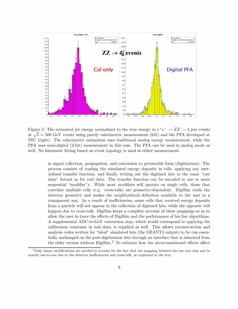
Figure 5: The estimated jet energy normalized to the true energy in e+e− → ZZ → 4 jets eventsat
√s = 500 GeV events using purely calorimetric measurement (left) and the PFA developed at
NIU (right). The calorimetric estimation uses traditional analog energy measurement, while thePFA uses semi-digital (2-bit) measurement in this case. The PFA can be used in analog mode aswell. No kinematic fitting based on event topology is used in either measurement.
in signal collection, propagation, and conversion to persistable form (digitization). Theprocess consists of reading the simulated energy deposits in cells, applying any user-defined transfer function, and finally writing out the digitized hits in the same “rawdata” format as for real data. The transfer function can be encoded in one or moresequential “modifier”s. While most modifiers will operate on single cells, those thatcorrelate multiple cells (e.g. cross-talk) are geometry-dependent. DigiSim reads thedetector geometry and makes the neighborhood definition available to the user in atransparent way. As a result of inefficiencies, some cells that received energy depositsfrom a particle will not appear in the collection of digitized hits, while the opposite willhappen due to cross-talk. DigiSim keeps a complete account of these mappings so as toallow the user to trace the effects of DigiSim and the performance of his/her algorithms.A supplemental ADC-to-GeV conversion step, which would correspond to applying thecalibration constants in real data, is supplied as well. This allows reconstruction andanalysis codes written for “ideal” simulated hits (the GEANT4 output) to be run essen-tially unchanged on the post-digitization hits through an interface that is inherited fromthe older version without DigiSim.2 To estimate how the above-mentioned effects affect
2Only minor modifications are needed to account for the fact that the mapping between the two sets may not beexactly one-to-one due to the detector inefficiencies and cross-talk, as explained in the text.
9

a given algorithm, one would then simply compare the results obtained using a realisticset of values for the detector effects to those obtained using an “identity” modifier. Theidentity modifier thus allows DigiSim to be permanently integrated into the simulationchain. A simplified class diagram of DigiSim is shown in Fig. 6, while Fig. 7 shows thescheme for transforming the list of GEANT4 energy deposits to digitized “raw hits”.Although so far we have only tested DigiSim for the calorimeter, it can be used forother subdetectors just as well. Applications to central tracking and muon system areanticipated in the near future.3
CellSelector
DigiSimProcessor
Processor Driver
DigiSimDriver
org.lcsimMARLIN
Digitizer
TempCalHit
AbstractCalHitModifier
GainDiscrimination Crosstalk DeadCell HotCellRandomNoise
GaussianNoise ExponentialNoise
CalHitMapMgr
SmearedGain SiPMSaturation
FunctionModifier
Java frameworkC++ framework
abstract
abstractabstract
Figure 6: A simplified class diagram of DigiSim. Full arrows represent inheritance. Hollow arrowsrepresent containment (solid) or use (dashed) relationships. New modifiers can be added easilyusing the existing ones as examples. Only the part dealing with calorimeter hits is shown in thisexample.
Here are some of the salient features of DigiSim:
• DigiSim adheres to the LCIO event data model, which is now universally acceptedby the ILC detector community. As a result, it can be used on all the differentdetector concepts - SiD, LDC, GLD, as well as test beam prototypes - even if theGEANT4 simulation is done by different programs, as is presently the case.4
3We have even received an enquiry for possible use of DigiSim in a particle astrophysics experiment.4The official GEANT4-based simulation programs are: SLIC for SiD, Mokka for LDC, Jupiter for GLD, and
10

TempCalHits TempCalHitsSimCalorimeterHits RawCalorimeterHits
RawHitsLCCollectionSimHitsLCCollection
Digitizer
Modifiers
Figure 7: The DigiSim chain in (the calorimeter part of) an event loop. Similar chains can beadded to other detector components as well.
• DigiSim has been implemented in both Java and C++. The Java implementationis designed for use in the org.lcsim environment adopted in the Americas, whilethe C++ implementation works within the Marlin framework, which is the officialstandard in Europe.
• DigiSim reads all its parameters from intuitive ASCII “steering” files that are read atrun time. Thus, the user does not have to recompile his/her reconstruction/analysiscode to change a DigiSim parameter.
• The steering files have the same format in the Java and C++ implementations - agiven steering file will produce the same effect in org.lcsim and in Marlin.
• DigiSim can be used either in a stand-alone mode to produce a persistent output, oras an on-the-fly preprocessor to the reconstruction program. In stand-alone mode,it produces output in the same format as that envisaged for the real data (except,of course, the simulation output also contains the “Monte Carlo truth”, which thereal data does not). Since DigiSim is fast compared to most pattern-recognitionalgorithms used in event reconstruction, the on-the-fly mode is suitable when onedoes not wish to write large intermediate output files on disk, e.g. when one ischanging the DigiSim parameters from one run to another. The stand-alone modemay be the better choice when a stable set of parameters has been agreed upon forsharing between multiple users.
An example of some of the effects simulated using DigiSim is shown in Fig. 8. Distri-bution functions of parameters such as efficiencies, cross-talk etc. may be expressed ineither continuous (analytic) or discreet (histogram) form. Since particle-flow algorithmsmust deal with individual showers in a jet, they are expected to be more sensitive to sys-tematic deviations at the single hit level than traditional jet-finding algorithms, wherea single post-reconstruction scaling often suffices to bring Monte Carlo in satisfactory
TBMokka for the CALICE test beam prototype.
11
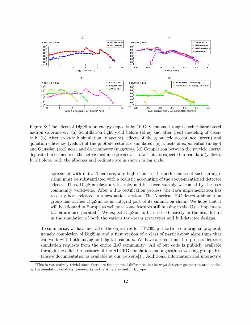
Figure 8: The effect of DigiSim on energy deposits by 10 GeV muons through a scintillator-basedhadron calorimeter: (a) Scintillation light yield before (blue) and after (red) modeling of cross-talk, (b) After cross-talk simulation (magenta), effects of the geometric acceptance (green) andquantum efficiency (yellow) of the photodetector are simulated, (c) Effects of exponential (indigo)and Gaussian (red) noise and discriminator (magenta), (d) Comparison between the particle energydeposited in elements of the active medium (green) vs. “raw” hits as expected in real data (yellow).In all plots, both the abscissa and ordinate are in shown in log scale.
agreement with data. Therefore, any high claim to the performance of such an algo-rithm must be substantiated with a realistic accounting of the above-mentioned detectoreffects. Thus, DigiSim plays a vital role, and has been warmly welcomed by the usercommunity worldwide. After a due certification process, the Java implementation hasrecently been released in a production version. The American ILC detector simulationgroup has ratified DigiSim as an integral part of its simulation chain. We hope that itwill be adopted in Europe as well once some features still missing in the C++ implemen-tation are incorporated.5 We expect DigiSim to be used extensively in the near futurein the simulation of both the various test-beam prototypes and full-detector designs.
To summarize, we have met all of the objectives for FY2005 put forth in our original proposal,namely completion of DigiSim and a first version of a class of particle-flow algorithms thatcan work with both analog and digital readouts. We have also continued to process detectorsimulation requests from the entire ILC community. All of our code is publicly availablethrough the official repository of the ALCPG simulation and algorithms working group. Ex-tensive documentation is available at our web site[1]. Additional information and interactive
5This is not entirely trivial since there are fundamental differences in the ways detector geometries are handledby the simulation/analysis frameworks in the Americas and in Europe.
12
help are provided on request.
The steady progress that we have achieved so far has been made possible by funding receivedfor this purpose during the past 4 fiscal years from DOE and NSF, in addition to generous, butless specific, funding from the Department of Education. In FY 2002 we received $45K fromthe DOE under its Advanced Detector Research program. An exploratory grant of $8.5Kwas awarded by the NSF in FY2003. In FY2004 and FY2005 we were awarded $35K and$44.5K, respectively, through LCDRD for our simulation software and algorithm developmentactivities.
Activities outlined in this proposal are synergistic with the proposals for hardware prototypingof different technology choices. We will continue to remain in close contact with the groupsinvolved in hardware development for the ECal and the HCal.
FY2006 Project Activities and DeliverablesExperience gained during the past year have led to recognition of new issues and some re-arrangement of priorities. In FY2006 we will integrate DigiSim into our reconstruction al-gorithms and study the effects of various detector imperfections on algorithm performance.Although DigiSim is ready for use, some improvements are planned in order to further en-hance its flexibility, ability to keep track of history (e.g. in the stand-alone mode, to record inthe output exactly what transformations have been applied), and error-reporting capabilities.
On the reconstruction algorithm development front, we will continue to improve pattern-recognition techniques, optimize the parameters of the algorithms, and compare simulationsof different options for active medium technology, absorber material, and geometry (segmen-tation). In particular, we need to understand how the performance of an algorithm dependson the radial segmentation of the HCal vis-a-vis its thickness in terms of interaction lengths.It is extremely important to strike the right balance between the thickness and the numberof layers since the geometric thickness of the calorimeter is severely constrained by consider-ations of the calorimeter and the magnet costs - so much so that the containment of hadronicshowers is a matter of concern in the SiD design.
Also, there are several issues that need to be addressed to fully assess the limit of PFAperformance:
• Much work is needed to minimize incorrect associations of “fragment” clusters: signifi-cant errors can result when a fragment originating from a neutral particle is incorrectlyassociated with a charged particle, or vice-versa.
• An important action item is to improve the propagation of charged particle tracksthrough the calorimeter using progressive fitting techniques that take into account theenergy loss and possible scattering. We have started working on this with C. Milsteneof Fermilab.
• The calorimeter designs currently on the table are not inherently compensating. Sepa-rate determination of response to electromagnetic and hadronic interactions in differentsections of the caloriemeter is high on our list of priorities. The dependence of these
13

responses on the polar angle needs to be studied as well. Since all cells in a given sectionhave fixed linear, rather than angular, dimensions, the difference may be significant.
• Another important issue is the differences in energy deposition patterns between dif-ferent types of neutral hadrons, e.g. n, n, and K 0
L. For a given kinetic energy, these
particles will deposit different amounts of visible energies in the calorimeter. We needto investigate how much we may stand to gain by identifying those differences.
We expect to accumulate a substantial volume of test beam data by the end of FY2006.Careful analysis of those will be critical for tuning our simulation and reconstuction programs.A significant part of our efforts will have to be devoted to this.
Comprehensive studies of critical physics processes will have to be carried out in order tounderstand the impact of the calorimeter performance on the physics program of the LinearCollider. These studies will employ both the analog and digital versions of our PFAs. Weplan to continue with further development of PFA-based jet-reconstruction and a partialassessment of physics reach vs calorimeter performance for the ILC.
Although we plan to start addressing most of the above issues during FY2006, consideringthe available resources, it is not realistic to expect to complete them all within the span ofone year. We intend to report on tangible progress by the end of FY2006 and hope to cometo reasonable conclusions on the key issues by the end of FY2007.
FY2007 Project Activities and DeliverablesIn FY2007, we will try to complete the studies listed above. We will also complete thephysics assessment with a clear statement on the desirability of a digital or analog optionfor the hadronic calorimeter. This will, of course, depend to a large extent on the test beamexperience as well. If all goes well, we will also start the development of parameterized sim-ulations of the particle-flow algorithms. The technology and geometry are expected to havebeen narrowed down by that time, thus setting the stage for such parametrized fast simu-lation for extensive physics studies. By the end of the third year we expect to produce, incollaboration with other groups, a fast simulation program based on PFAs. In addition, ex-tensive benchmarking of critical physics processes, as well as evolution of pattern-recognitionand reconstruction algorithms will continue.
Budget justification:The above activities will be carried out by NICADD staff members. Specifically, one ResearchScientist has been working full time on the proposed software R&D, and is expected tocontinue likewise through the next 2 years. We request that half of his salary be borne bythe grant in question.
Communication of progress and exchange of ideas through international workshops and con-ferences will be crucial for our endeavor to have a global impact. Based on the FY2005experience, we estimate five domestic and two international trips per year. A part of thesetravel expenses should be covered as well.
14
Fringe benefits to personnel at NIU’s mandated rate of 52% of salary, and indirect costs atthe off-site rate of 26% (instead of the usual 45%, since the requested personnel will work inoffices at Fermilab allocated specifically for ILC R& D) are included in the requested amount.
Two-year budget, in then-year K$
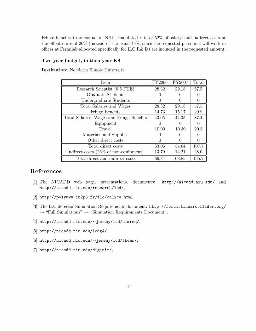
Institution: Northern Illinois University
Item FY2006 FY2007 Total
Research Scientist (0.5 FTE) 28.32 29.18 57.5Graduate Students 0 0 0
Undergraduate Students 0 0 0
Total Salaries and Wages 28.32 29.18 57.5Fringe Benefits 14.73 15.17 29.9
Total Salaries, Wages and Fringe Benefits 43.05 44.35 87.4Equipment 0 0 0
Travel 10.00 10.30 20.3Materials and Supplies 0 0 0
Other direct costs 0 0 0
Total direct costs 53.05 54.64 107.7Indirect costs (26% of non-equipment) 13.79 14.21 28.0
Total direct and indirect costs 66.84 68.85 135.7
References
[1] The NICADD web page, presentations, documents: http://nicadd.niu.edu/ andhttp://nicadd.niu.edu/research/lcd/,
[2] http://polywww.in2p3.fr/flc/calice.html,
[3] The ILC detector Simulation Requirements document: http://forum.linearcollider.org/→ “Full Simulations” → “Simulation Requirements Document”.
[4] http://nicadd.niu.edu/∼jeremy/lcd/simreq/,
[5] http://nicadd.niu.edu/lcdg4/,
[6] http://nicadd.niu.edu/∼jeremy/lcd/tbeam/,
[7] http://nicadd.niu.edu/digisim/,
15

Summary of visit to IHEP, Beijing, and discussions on Princeton-IHEP
collaboration for ILC R&D
Changguo Lu, Princeton University
I visited IHEP, Beijing on 1/12 -19/2006. Purpose of the visit The main purpose of my visit is getting first hand knowledge from IHEP and Gaonenkedi Co. on their new RPC technology, exchange the R&D progress, discussing how to establish the collaboration between IHEP and Princeton, and to plan further R&D work. Status of BESIII RPC’s. During ICHEP04’ the IHEP muon group reported that they have collaborated with Beijing Gaonenkedi Science & Technology Co. and developed a new type of highly resistive plate. The RPC with this type of resistive plate as its electrodes needn’t use Linseed oil to coat the inner surface, because the surface is so smooth. The company had manufactured more than 1000 RPCs for the BESIII muon system. The BESIII muon system installation had started on July, 2005 and successfully finished on October of the same year. After the installation a brief performance checkup took place, with encouraging results. Further more demanding tests will be carried out opportunistically during the remaining year before commissioning of the entire BESIII detector system. According to the experience of BaBar and Belle RPC systems, the pre-commissioning long term test is very essential, as it revealed unexpected weaknesses and/or problems. I have emphasized the importance of this step, and hope my message is received with proper priority by our IHEP colleagues.
Figure 1. Installed BESIII barrel muon detector.
Visit to Geonenkedi Company. During the visit to Gaonenkedi Co I had a long conversation with their general manager Zhao Haquan and the chief engineer Su Minfa. That conversation gave me a deep impression. It leaves me no doubt about their capability and enthusiasm for the R&D work on developing even better resistive plates. Zhao was a research engineer at IHEP who has good knowledge on making high energy physics detectors, and Su Minfa was the chief engineer of Beijing Insulating Material Factory. They have a broad network of facilities in Beijing area, which can materialize good ideas rather quickly. We can therefore expect to receive prompt feedback from them concerning results on their new plates from studies at Princeton. I think we can establish a good working relationship with them, and thereby solve some of the troubles that have bothered the world RPC community for a long time. Working at IHEP lab to test the efficiency of their RPC in avalanche mode On my visit I spent a lot of time in their lab, working with graduate students there. I learned that CMS and PHENIX have obtained some prototypes from IHEP, and studied the performance in avalanche mode. The test results are rather disappointing – they claim the efficiency of IHEP RPC in avalanche mode can only reach ~90%. There is no any plausible explanation for this peculiar behavior – good efficiency in streamer mode and lower efficiency in avalanche mode. The IHEP group had worked on this problem for some time, but due to lack of proper preamplifiers there was no positive result. On my visit I brought our preamplifier board with me, which we use for BaBar endcap avalanche RPC chambers, and worked with them to test their chamber. The preliminary test result shows that the BESIII-type RPC also can reach very high efficiency in avalanche mode, and therefore I feel the puzzle is solved. Visit at test beam facility at IHEP The BEPC test beam facility was constructed in March 2003. The first mid-high energy test beam line in China, it provides a precious in-house experimental tool for detector R&D, and has made great improvements since its construction. The configuration of the test beam line is shown in figure 2. There are two test beam lines that can be used for different test purposes. The beam line #2 provide high intensity beam that is useful for detector aging studies. For the beam line #3, at present the total rate for multiple particles (operation momentum at 800MeV, consisting of electron, pion and proton) rate reaches 8-9 HZ at maximum, and the rate for an individual species is about 2 Hz. The intensity will increase when BEPCII starts running in near future, with electron beams at 50Hz, 100 bunches per second. The test beam line, equipped with Cherenkov counter, MWPCs, scintillation counters and data acquisition system, has been used for testing various BESIII subsystem prototypes. In particular, they have used it for studying the time resolution of TOF, the energy and spatial resolution of EMC, the performance of a full length MDC prototype and the efficiency of muon detectors. These tests have been going on for two years.
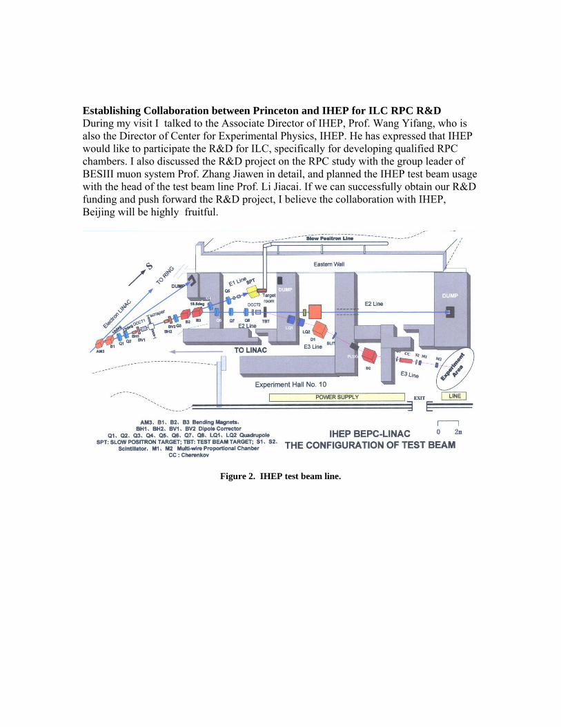
Establishing Collaboration between Princeton and IHEP for ILC RPC R&D During my visit I talked to the Associate Director of IHEP, Prof. Wang Yifang, who is also the Director of Center for Experimental Physics, IHEP. He has expressed that IHEP would like to participate the R&D for ILC, specifically for developing qualified RPC chambers. I also discussed the R&D project on the RPC study with the group leader of BESIII muon system Prof. Zhang Jiawen in detail, and planned the IHEP test beam usage with the head of the test beam line Prof. Li Jiacai. If we can successfully obtain our R&D funding and push forward the R&D project, I believe the collaboration with IHEP, Beijing will be highly fruitful.
Figure 2. IHEP test beam line.

December 19th, 2005
1�
Modular DAQ Development for the ILC SiD by
Satish Dhawan, Senior Research Scientist, Yale Physics Department, phone: 432-3377
and Homer Neal, Associate Professor, Yale Physics Department, phone: 432-3382
1. Introduction
The current instrument standards developed specially for the physics research community that have served so well for up to four decades are in need of a major structural overhaul in order to accommodate new technologies and to achieve significantly higher system performance for new large research machines. Intelligent chips with processors, programmable logic and multi-gigabit serial communications, have become dominant in the commercial computer and instrument industry. The method of communication between modules has changed completely from a shared parallel data bus to multiple serial buses that can provide much faster and cheaper communications and packaging. Past standards such as NIM, CAMAC and Fastbus were designed by a collaboration of users of large laboratories and industry, and the resulting platforms instantly commercialized. Lab efforts to upgrade standards have been dormant for more than a decade and industry has moved rapidly ahead in designing platforms with advanced features only dreamed of in the past. Our goal is to collaborate with industry groups working on new standards to select specific approaches for the various segments of the physics research communities.
A 1980’s USAEC study of the economic impact of the first two decades of standards in physics research had saved approximately $2B in laboratory costs. However, starting in the mid-1980’s the utilization of the standard modules was greatly reduced due to the sudden availability of new chip technologies in the physics large detector field. The functionality of entire modules was in some cases reduced to a single chip, and the requirements of detectors to minimize metal and cable mass inside the detectors caused much of the module business to move to custom chips and chip-and-board assemblies. Although there is a case to be made for bringing modernized standards to bear on custom detector electronics, no organized collaborative effort has been mounted for the last two decades.
The important global interoperability features will be preserved in the new standard. Adopting new standards broadly will result in a strong synergy among and between project groups, technical interest groups and industry. This will benefit design and lower the costs of future accelerator and detector instrumentation and intelligent power systems. Judging from past performance, a new standard platform should remain current for at least two decades.
2. Objectives of the Proposed Project: For particle detectors, having a common design for transporting the signals off of
the detector will insure compatibility, increase reliability, decrease costs and facilitate the maintenance of the detector. These factors are of utmost importance to the proposed new

December 19th, 2005
2�
International Linear Collider (ILC). This multi billion dollar project which involves an approximately 30 km electron positron collider operating at a center of mass energy of 500 GeV is still in the R&D stage. It is gaining momentum as the international collaboration focuses on the goal of a full conceptual design and cost model, to be supported by relevant R&D, in 2006. Simulations have demonstrated that major increases in subsystem component reliability are needed before an acceptable overall machine reliability can be achieved. Starting with the well-defined needs of the ILC as a basis for evaluation of all accelerator and detector electronics, we propose to evaluate the emerging industry standards and make specific implementation choices for de facto project standards.
The telecommunications industry has recently collaborated to field a standard (Advanced Telecom Computing Architecture (ATCA) in which modular systems are designed for a downtime of less than five minutes in a year. We intend to apply these standards with an appropriate choice of IO bus technology to create a common system for transporting signals from the custom on-detector readout electronics to the off-detector processing PCs.
We have compared the available IO buses (Ethernet, USB, CAMAC, VME, PCI) and have identified the PCIe (Peripheral Component Interconnect express) design as the most promising for future large detector communications. We propose to design the readout for the ILC SiD forward colorimeter detector using PCIe and the ATCA standards and related micro ATCA (mATCA). The system will consist serial to parallel data FPGA concentrator connected to an end point controller. Further we propose a Wave Form Digitizer with high resolution and high speed ADCs to process the pulse shapes followed by limited on detector FPGA processing to perform operations such as zero suppression. Then an End Point Controller (EPC) will produce standard packets to be transferred over the 4 lane PCI express IO bus at a rate of 1 GB/s. This low voltage LVDS signaling serial bus can then be easily converted to a light signal carried over optical fibers to PCs that would then further process the signals.
On DetectorOn DetectorOn DetectorOn Detector Off DetectorOff DetectorOff DetectorOff Detector
From the End Point Controller to the PCs all would be low-cost mainstream reliable modern electronics compliant with the PCIe/ATCA standards.
Waveform Digitizer
FPGA (doing minimal processing of the signal)
End Point Controller (formats standard packets for PCIe)
Off detector PC processing farm
Optical fiber: Up to 5Gb/s

December 19th, 2005
3�
Through connections we have established with Intel on their development of copper to fiber adapter for the PCIe. The transmission rate will be up to 5 Gb/s per fiber and the far end can plug into PC adapter cards such as Infiniband, PCI express/ASI, Storage systems etc. This will be mainstream technology thus keeping the costs down. The estimated cost for the high end performance of 20 (4x 5.0) Gb/s link is estimated at $150 in 1 K quantity We intend to develop the essential modules for applying these standards here at Yale. After this readout has been proven to be an effective solution for the forward calorimeter, the setup will then be available as a test facility for electronics development for the other sub-detectors for the SiD. We have already started discussions with the hadron calorimeter group about using this standard. Application of this standard to all sub-detectors at an early stage of the SiD development will insure compatibility between sub-detectors and facilitate the overall development of the electronics for each sub-detector. We will be carrying out this development work in co-operation with the new ILC group at Brookhaven National Laboratory. Our close proximity to BNL, their interest in SiD detector development and personal connections with members of the group make this a very fruitful relationship.
3. Broader Impact The standards that we are developing will be widely applicable beyond the ILC
SiD. It is likely that this will also be useful for the ILC accelerator controls and it is highly probable that other large research projects such as ITER will use this standard. We have already been in touch with US ITER project office and they have expressed strong interest.
Yale will become the central facility at the international level where designers of research electronics will be able to come to test the compatibility and interoperability of their system with the ATCA/PCIe standards. Such facilities do not exist at any laboratory or university because of the expense. Having a central facility for testing will minimize the effort and costs for such tests. It will not be limited to the ILC. It is intended that small working groups with laboratories and industry will be formed to develop demonstration prototypes of typical applications in various fields.
In summary, it is time to establish a new standard for the data buses needed for laboratory experiments in order to profit from advantages of speed, reliability and lower cost of newer technology. Establishing this new standard will also bring quicker design and staging of experiments; multiple vendor choices in procurement to gain economic advantage; high availability (up-time) of running experiments through easy substitution of failed modules; shorter time-to-market for vendors and in-house designers through conformance to standard design rules and practices. The PCI express IO bus combined with the ATCA design protocols appears to be the best choice for bringing data transfer in laboratory detectors into the modern era. We propose to establish a facility whereby this technology can be applied to prototypes of future physics detectors as well as to traditionally packaged modules in accelerator and detector central controls, distributed controls, data acquisition, front-end instrumentation, and high-speed communications and

December 19th, 2005
4�
timing systems.
4. Work Plan and Deliverables We are proposing here a three-year R&D program to address the issues discussed above. We foresee the following activities for the first year.
4.1 Work Plan Year 1 • Study the design of a complete PCIe/ATCA compliant system for reading
out the forward SiD calorimeter and DHCAL.
• Develop an FPGA VHDL code to accept serial stream data and convert to parallel bus for transmission via an end point controller with the far end to be plugged directly into a PC.
• Explore porting our CAMAC wave form digitizer designs using ADCs
(10-16 bits sampling rates =>150 MHz) and FPGA with VHDL code for zero suppression and feed parallel data to an end point controller.
• Collaborate with Intel to implement fiber optics transmission of the signals from the End Point Controllers to PCs
• Work with ILC Detector and Accelerator Control standards group

December 19th, 2005
5�
5. Budget Estimates for the 1st year
Yale Budget for Instrumentation STANDARDS
Subscriptions for Specifications of Industry Standards - PICMG $ 1,750 1 or 2 Undergraduates: 12 hours/week + summer $ 5,000 Micro ATCA Crate and modules $ 6,000 Engineering $ 10,000 IP Cores for the Design of PCIe Logic in FPGA's $ 7,000 Xilinx Corp. PCI Express Development Board $ 3,000 PLX Corp. PCI Express Development Board $ 450 Electronic Components $ 5,000
Travel $ 1,800
Total = $ 40,000
Budget Explanations PICMG is the initiator of ATCA Specification / Standards PCI Express is a new high speed serial data bus in Intel's PCs ATCA (Advanced Telecom Computing architecture) is a new standard for telecommunication gear. FPGA: Field Programmable Gate Arrays: Program it for user logic IP Core: Intellectual Property Cores for the design of PCIe logic and algorithms
6. Principal Investigators Satish K. Dhawan, Senior Research Scientist has been at Yale since 1967. BSEE from India, MS University of Iowa, EE Columbia University, PhD in Experimental physics from University of Tsukuba, Japan. He has been part of the NIM (Nuclear Instrument Standards), CAMAC and FASTCAMAC standards for the past 40 years. He developed large amount of Instrumentation for the Yale University experiments at BNL, Los Alamos National Laboratory, SLAC, CERN, Fermilab and PSI in Switzerland. Waveform digitizers and FASTCAMAC were developed jointly with companies under DoE SBIRs. Relevant publications:
December 19th, 2005
6�
Introduction to PCI Express – A New High Speed Serial Data Bus. Satish Dhawan. Presented at the IEEE Nuclear Science Symposium, San Juan, Puerto Rico. Submitted to IEEE Transaction on Nuclear Science An Introduction to FASTCAMAC (60 Megabytes/sec in CAMAC?), S.K. Dhawan, C. Hubbard, T. Radway, and R. Sumner, in Fusion Technology 1996, Proceedings of the 19th Symposium on Fusion Technology, ed. C. Varandas and F. Serra (Elsevier, Amsterdam, 1997), p. 961-964. Precision Deuteron NMR Signal Measurement with the NA47 Polarized Target, D.G. Crabb, S.K.
Dhawan, N. Hayashi, and A. Rijllart, IEEE Trans. on Nucl. Sci., 43 (3), 2128 (1996). A Quad 500 MHz waveform digitizer with differential trigger for use in the muon g-2 experiment. S. Dhawan, et., al. Nucl. Inst. & Method. In Phys. Res. A450 391-398 (2000). ZEUS GTT FARM. In preparation to be submitted to NIM. Homer A. Neal, Associate Professor of Physics at Yale since 1999. BA in physics from Cornell University, PhD in physics from Stanford University. He has worked on the Stanford Linear Accelerator Center Large Detector (SLD), followed by several years as a CERN scientific associate at the European Laboratory for Particle Physics (CERN) working on the OPAL experiment, and while at Yale he has headed the Yale effort on the BaBar detector experiment at SLAC, worked on detector design for the ILC, and the Compact Muon Solenoid experiment at CERN which involves both detector and software development. Relevant publications: Linear collider physics resource book for Snowmass 2001, T. Abe et al. [American Linear Collider Working Group Collaboration], SLAC-R-570 Resource book for Snowmass 2001, 30 Jun - 21 Jul 2001, Snowmass, Colorado Optimizing the Design of a Small Central Tracker, H. Neal, Proceedings of the International Workshop on Linear Colliders, Sitges, Spain, April 28th, 1999. Radiation monitoring and beam dump system of the OPAL silicon microvertex detector, H. Neal et al., Nucl.Instrum.Meth.A403:351-362, 1998. Performance of the SLD Central Drift Chamber, H. Neal et al. Nucl.Instrum.Meth.A367:111-114, January 1995.

Revised Participation Data Tables
Participation Data
Number of projects, regardless of funding status year 1 year 2 year 3 this yearAccelerator Physics total 33 29 30 37 Luminosity, Energy, Polarization total 9 9 9 7 Vertex Detector total 3 3 1 5 Tracking total 11 11 12 9 Calorimetry total 12 13 10 12 Muon and Particle ID Systems total 3 3 3 3 Total 71 68 65 73
Funds already awarded, or promised: DOE + NSF FY04 FY05 FY06 Accelerator Physics total $442,430 $506,780 $458,015Luminosity, Energy, Polarization total $75,000 $112,250 $0Vertex Detector total $72,000 $64,500 $0Tracking total $152,000 $211,250 $0Calorimetry total $320,000 $277,500 $0Muon and Particle ID Systems total $26,000 $27,000 $0Total $1,087,430 $1,199,280 $458,015
Funding requested by new (and renewal) proposals FY06 FY07
Accelerator Physics total $3,497,716 $3,423,080Luminosity, Energy, Polarization total $355,574 $376,156Vertex Detector total $279,237 $396,370Tracking total $630,914 $733,100Calorimetry total $1,198,480 $1,267,171Muon and Particle ID Systems total $363,750 $428,902Total $6,325,671 $6,624,779

Status of FY06 support funding
promisednew
proposal renewal proposal total
Accelerator Physics total 11 23 3 37 Luminosity, Energy, Polarization total 0 3 4 7 Vertex Detector total 0 4 1 5 Tracking total 0 4 5 9 Calorimetry total 0 6 6 12 Muon and Particle ID Systems total 0 1 2 3 Total 11 41 21 73
Participation by institutions year 1 year 2 year 3 this yearU.S. Universities 47 48 49 52 National and industrial laboratories 7 5 7 8 Foreign institutions 11 11 23 25 Total 65 64 79 85
Authors year 1 year 2 year 3 this yearU.S. Universities 209 220 204 252 National and industrial laboratories 70 58 71 77 Foreign institutions 18 25 55 42 Total 297 303 330 371