mapping the commodore 128 - cubic playerdoj/c64/mapping128.pdf · mapping the commodore 128 ottis...
TRANSCRIPT

MAPPINGTHE
COMMODORE128
Ottis R. Cowper
COMPUTE! Publications,IncPart or ABC Consumer Magazines. Inc.One of the ABC Publishing Companies
Greensboro, North Carolina

I
Copyright 1986^ COMPUTE! Publications, Inc. All rights reserved.
Reproduction or translation of any part of this work beyond that permitted bySections 107 and 108 of the United States Copyright Act without the permission ofthe copyright owner is unlawful.
Printed in the United States of America
1 0 9 8 7 6 5 4 3 2 1
ISBN 0-87455-060-2
The author and publisher have made every effort in the preparation of this book to insure the ac-curacy of the programs and information However, the information and programs in this book aresold without warranty, either express or implied. Neither the author nor COMPUTE! Publications,Inc. will be liable for any damages caused or alleged to be caused direct!)', indirectly, incidentally,or consequentially by the programs or information in this book.
The opinions expressed in this book are solely those of the author and are not necessarily those ofCOMPUTE! Publications, Inc.
COMPUTE! Publications, Inc., Post Office Boy 5406, Greensboro, NC 27403, (919)275-9809, is part of ABC Consumer Magazines, Inc., one of the ABC Publishing Com-panies, and is not associated with any manufacturer of personal computers. Commo-dore 64 and Commodore 128 are trademarks of Commodore Electronics Limited,
Contents
Preface v
Introduction vii
1. Memory Organization 1
2. Common Working Storage Area 13
3. Bank 0 Working Storage Area 115
4. RAM Usage 181
5. BASIC ROM 195
6. Machine Language Monitor ROM 241
7. Screen Editor ROM 267
8. I/O Chip Registers, Color RAM, and Character ROM 331
9. Kernal ROM 509
Appendices 617
A. Interrupts/Todrf Heimarck 619
B. Bugs and Quirks in 128 ROM 625
C. Character, Screen, and Keyboard Codes 629
D. Musical Note Frequencies 645
E. 64/128 Memory Map Cross Reference 649
P. BASIC Keyword Index 657
G. Index of Locations and Routines 663

PrefaceThe random access memory (RAM), read-only memory (ROM),and interface hardware chips in your Commodore 128 are likepostal stations with hundreds of thousands of mailboxes, eachof which can hold a single character, or byte of information.This book is a map of all of those memory locations, but it'smore than just a list of addresses. It's also a thorough discus-sion of how the locations are used by the computer, and, moreimportantly, how you can take advantage of this informationto write more powerful programs.
Why a mapping book? The 128's BASIC is the mostpowerful version yet in a Commodore computer. It could beargued that there's little need to get "under the hood" of the128, since most of the functions that required lots of PEEKsand POKEs and an intimate understanding of internal hard-ware functioning in earlier models like the Commodore 64 cannow be handled by simple BASIC statements on the 128.While it may be true that the 128's advanced BASIC makesprogramming easier, complete control over all the computer'sfeatures belongs only to those who understand the secrets ofhow the system operates. The purpose of this book is to un-lock those secrets. The information is valuable for both begin-ning BASIC and advanced machine language programmers.
The standard features provided by the 128 are often plainvanilla, giving only the barest hint of the full capabilities ofthe computer. Would you like to set up a Dvorak keyboardthat will work with almost any program? See the discussion ofthe keyboard table pointers in Chapter 2. How about an 80-column X 50-line screen display on your RGB monitor? Theexplanation of the VDC chip registers in Chapter 8 explainsthe necessary steps. Do you want to learn how the computersends data over the serial bus? The process is described inChapter 9. In fact, you'll find here the answers to most of yourquestions about the 128. And these answers are written in un-derstandable, clear prose.
This book is the result of painstaking disassembly and de-ciphering of the Commodore 128 ROMs—a task that requiredgallons of midnight oil. Commodore's BASIC and operating

system are now nearly ten years old. The ROM routines havemany twists and turns where various Commodore program-mers have made additions and enhancements along the way.Although the 128 is internally quite different from the Com-modore 64, there are similarities. As a result, several previousCOMPUTE! books for the 64 provided invaluable assistance inattempts to understand some of the intricacies. I'm particularlyindebted to Sheldon Leemon for Mapping the Commodore 64,and to Dan Heeb for his two volumes of Commodore 64 andV1C-20 Tool Kit: BASIC and Kernal.
Every effort has been made to insure that the informationprovided here is accurate, but in a project of this size andscope it is inevitable that some errors will creep in. Pleasesend any corrections you may discover to the attention of theBook Editor at COMPUTE! Publications in Greensboro. Youcan also send electronic mail messages concerning this book toCompuServe user ID 73317,1143 or to BIX (Byte InformationExchange) user name ottis.
I'd like to salute my wife Gail for moral and logisticalsupport far above and beyond the call of duty. I'd also like tothank the COMPUTE! staff for patience shown when thisproject dragged on months longer than anticipated. Finally, I'dlike to dedicate this book to George and George, departingand arriving as the work took shape.
VI

IntroductionThis memory map is a guide to the way a Commodore 128 in128 mode uses and manipulates its RAM and ROM. No at-tempt is made here to provide detailed coverage of the 128's64 mode. A Commodore 128 in 64 mode doesn't just emulatea Commodore 64; for all practical purposes it is a 64, withcompletely separate Kernal and BASIC ROM. The memorymap of the Commodore 64 mode (and its BASIC 2.0) is cov-ered in complete detail in COMPUTERS Mapping the Commo-dore 64. However, Appendix E discusses those 128 featuresavailable in 64 mode, and provides a cross reference of impor-tant memory locations for 64 and 128 modes—informationthat will be useful in translating Commodore 64 machine lan-guage routines for use in 128 mode.
Nor does this book make any attempt to map the way the128's CP/M mode uses memory. CP/M is a large and com-plex operating system, and a CP/M mode memory map wouldeasily fill another entire volume. Moreover, the major portionof CP/M is loaded from disk instead of being permanentlystored in ROM. As a result, CP/M is subject to more frequentmodification; so far, in the short life of the 128, there havebeen at least three major revisions. Detailed technical infor-mation on Commodore 128 CP/M is available in the bookCP/M Plus User's Guide /Programmer's Guide/System Guide,available directly from Commodore.
Because this book is intended as a reference for intermedi-ate to advanced BASIC and machine language programmers,no attempt is made to provide simple explanations of all theconcepts discussed. The discussions assume familiarity withelementary computer concepts such as bits and bytes, andwith memory quantity units such as a page (256 bytes) or a K(kilobyte, 1024 bytes). The book also assumes familiarity withthe binary and hexadecimal numbering systems, although dec-imal equivalents are usually provided.
Hexadecimal numbers in the text are always preceded bya dollar sign ($), the standard 8502 nomenclature for hex.Decimal numbers appear without any prefix. When you see apair of numbers separated by a slash (/), the first number is
vu

decimal and the second is hexadecimal, unless otherwise indi-cated. This book uses the machine language monitor's conven-tion of preceding binary numbers with a percent (%) sign. Forexample, %11 indicates the binary value equivalent to decimal3, not decimal 11.
When you see numbers mentioned in this book, it shouldbe obvious from the context whether the number refers to anaddress or a value. Where there could have been confusion, theterms value and location or address specify what is meant. Inkeeping with common practice, only two hexadecimal digits aregenerally used when discussing addresses in the first page ofmemory (zero page). That is, addresses 0-255 are usually writ-ten as $00-$FF. Four hexadecimal digits are used for all otheraddresses. For example, location 256 will be written as $0100,
By nature, the computer prefers to deal with whole num-bers and doesn't handle fractions easily. Floating point is themethod used to manipulate whole and fractional decimalnumbers in 128 BASIC. Floating point also enables very largenumbers to be handled in only a few bytes. All mathematicaloperations in BASIC are performed in floating point. (Whenyou specify integer variables in a mathematical operation, theinteger value is converted to floating point for the operation;then the result is reconverted to integer format.) However, be-cause floating point is a rather complex subject, it is not ex-plained in detail in this book even though it is mentionedextensively in Chapter 5. If you are interested in the innerworkings of floating point, refer to the excellent discussion ofthe topic in COMPUTED VIC-20 and Commodore 64 Tool Kit:BASIC, by Dan Heeb. Although not written specifically for the128, all the information about floating point applies to BASIC7.0 as well.
Several terms used freely in this book need clarification.Most locations discussed in Chapters 2 and 3 are either point-ers, vectors, or flags. Pointers and vectors refer to a pair ofmemory locations that hold an address. Two-byte address val-ues in pointers and vectors are stored in low-byte/high-byteorder. That is, the least significant byte of the address shouldbe stored in the first byte of the pointer or vector, and themost significant byte of the address in the second pointer orvector byte.
The difference between pointers and vectors is that apointer (as the name implies) points to an address from which
vm
data is to be retrieved or in which data is to be stored,whereas a vector points to the address of a routine to beexecuted.
A flag is a memory location in which individual bits areused to signal particular conditions. A binary bit can have oneof two conditions, %0 or %1 (also referred to as clear and set,respectively). The term comes from the analogy of flags, likethose on rural mailboxes, that can be either lowered or raised(there's no half-mast in binary). An example is the activescreen flag, location 215/$D7. Bit 7 of the location is clear(%0) when the 40-column display is active, or set (%1) whenthe 80-column display is active. (You'll find that flag locationsoften use bit 7 because that bit can be tested very easily inmachine language with the BMI and BPL instructions.)
Chapter 1 provides a brief introduction to the way the128 arranges and manages its memory resources. That chapterand Chapter 4 are the only chapters in the book intended tobe read from beginning to end. The remaining chapters de-scribe the use or function of various areas of memory andshould be used as an encyclopedic reference. The chaptersgenerally cover memory in ascending address order, startingwith zero page in Chapter 2 and ending with the Kernal jumptable at the very top of memory in Chapter 9. Each entry inChapters 2-9 consists of the decimal and hexadecimal addressof the location or routine; a label, if one is commonly used; ashort statement of the function of the location or routine; anda short description of how the location or routine is used.
IX

MemoryOrganizationThe memory arrangement of a Commodore 128 in 128 modeis much different and more complex than that of any of itsCommodore predecessors. As a result, it's necessary to under-stand how the 128 organizes and manages its memory resourcesbefore beginning a detailed examination of how those re-sources are used. Of the computer's three possible personal-ities, 128 mode is the default. Unless you take some otheraction—holding down the Commodore key, inserting a Com-modore 64 cartridge, placing a CP/M boot disk in the drive—the computer comes up in 128 mode when you turn it on. Asthe native mode of the system, 128 mode makes the mostcomplete use of the available memory resources.
You might be interested to learn that, while 128 mode isthe default operating mode, the computer always starts out inCP/M mode. When you first turn on power, the Z80 micro-processor has control before the 8502 is allowed to take over.There are only a few signs of this: two short routines are cop-ied into bank 0 RAM. One, at 65488/$FFD0, is an 8502 MLroutine that surrenders control to the Z80; the other, at65504/$FFEO, is a Z80 ML routine that surrenders control tothe 8502. There are no routines in any of the 128 mode ROMsto perform this initialization. However, once the Z80 com-pletes its initialization sequence, it turns the system over tothe 8502 and 128 mode, and does not go back to CP/M modeunless a CP/M disk is booted.
128 ModeThe 128 mode configuration includes 128K of random accessmemory (RAM) in two 64K blocks, a 28K BASIC interpreter inread only memory (ROM), a 4K machine language monitor inROM, 4K of screen editor routines in ROM, 8K of Kernal op-erating system routines in ROM, a 4K character pattern ROM,and 4K of address space for hardware chip registers (with twoseparate IK banks of color RAM). The design also provides for
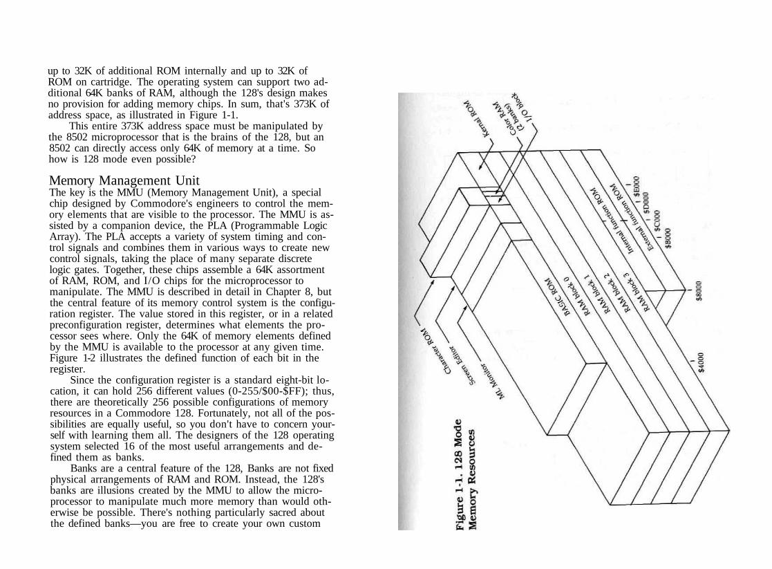
up to 32K of additional ROM internally and up to 32K ofROM on cartridge. The operating system can support two ad-ditional 64K banks of RAM, although the 128's design makesno provision for adding memory chips. In sum, that's 373K ofaddress space, as illustrated in Figure 1-1.
This entire 373K address space must be manipulated bythe 8502 microprocessor that is the brains of the 128, but an8502 can directly access only 64K of memory at a time. Sohow is 128 mode even possible?
Memory Management UnitThe key is the MMU (Memory Management Unit), a specialchip designed by Commodore's engineers to control the mem-ory elements that are visible to the processor. The MMU is as-sisted by a companion device, the PLA (Programmable LogicArray). The PLA accepts a variety of system timing and con-trol signals and combines them in various ways to create newcontrol signals, taking the place of many separate discretelogic gates. Together, these chips assemble a 64K assortmentof RAM, ROM, and I/O chips for the microprocessor tomanipulate. The MMU is described in detail in Chapter 8, butthe central feature of its memory control system is the configu-ration register. The value stored in this register, or in a relatedpreconfiguration register, determines what elements the pro-cessor sees where. Only the 64K of memory elements definedby the MMU is available to the processor at any given time.Figure 1-2 illustrates the defined function of each bit in theregister.
Since the configuration register is a standard eight-bit lo-cation, it can hold 256 different values (0-255/$00-$FF); thus,there are theoretically 256 possible configurations of memoryresources in a Commodore 128. Fortunately, not all of the pos-sibilities are equally useful, so you don't have to concern your-self with learning them all. The designers of the 128 operatingsystem selected 16 of the most useful arrangements and de-fined them as banks.
Banks are a central feature of the 128, Banks are not fixedphysical arrangements of RAM and ROM. Instead, the 128'sbanks are illusions created by the MMU to allow the micro-processor to manipulate much more memory than would oth-erwise be possible. There's nothing particularly sacred aboutthe defined banks—you are free to create your own custom

configurations (see the discussion of the MMU in Chapter 8for details)—but it is usually more convenient to work in oneof the predefined banks. Table 1-1 shows the bank configura-tions defined by the 128's operating system.
Figure 1-2. MMU Configuration Register
Table 1-1. Standard Bank Configurations
Bank0/$00i/$oi
2/$02
3/$03
4/$04
5/$05
6/$ 06
7/$07
8/$08
9/$09
ConfigurationRegisterSetting63/$3F
127/$7F
191/$BF
255/SFF
22/$16
86/$56
150/$96
214/$D6
42/$2A
106/$6A
Addresses$0000-$FFFF$0000-$03FF$0400-$FFFF$0000-$03FF$0400-$FFFF$0000-$03FF$0400-$FFFF$0000-$7FFF$8000-$CFFF$D000-$DFFF$E000-$FFFF$0000-$03FF$0400-$7FFF$8000-$CFFF$D000-$DFFF$E000-$FFFF$0000-$03FF$0400-$7FFF$8000-$CFFF$D00O-$DFFF$EO00-$FFFF$0000-$03FF$0400-$7FFF$8000-$CFFF$D0O0-$DFFF$E000-$FFFF$0000-$7FFF$8000-$CFFF$D000-$DFFF$E000-$FFFF$0000~$03FF$0400-$7FFF$8000-$CFFF$D000-$DFFF$EO00-$FFFF
ContentsRAM from block 0RAM from block 0RAM from block 1RAM from block 0RAM from block 2RAM from block 0RAM from block 3RAM from block 0Internal function ROMI/O blockInternal function ROMRAM from block 0RAM from block 1Internal function ROMI/O blockInternal function ROMRAM from block 0RAM from block 2Internal function ROMI/O blockInternal function ROMRAM from block 0RAM from block 3Internal function ROMI/O blockInternal function ROMRAM from block 0External function ROMI/O blockExternal function ROMRAM from block 0RAM from block 1External function ROMI/O blockExternal function ROM

ConfigurationRegister
Bank Setting10/$0A 170/$AA
Addresses$0000-$03FF$0400-$7FFF$8000-$CFFF$D0O0-$DFFF$EO00-$FFFF
ContentsRAM from block 0RAM from block 2External function ROMI/O blockExternal function ROM
11/$OB 234/$EA $0000-$03FF RAM from block 0$0400-$7FFF RAM from block 3$8000-$CFFF External function ROM$D00O-$DFFF I/O block$E000-$FFFF External function ROM
12/$0C 6/$06 $0000-$7FFF RAM from block 0$8000-$BFFF Internal function ROM$C00O-$CFFF System ROM (screen
editor)$DO00~$DFFF I/O block$E00O-$FFFF System ROM (Kernal)
13/$0D 10/$0A $0000-$7FFF RAM from block 0$8000-$BFFF External function ROM$CO00-$CFFF System ROM {screen
editor}$D0O0-$DFFF I/O block$EO00-$FFFF System ROM (Kernal)
14/$0E l/$01 $0000-$3FFF RAM from block 0$4000-$CFFF System ROM (BASIC
7.0, ML monitor, screeneditor)
$D000-$DFFF Character ROM$E0O0-$FFFF System ROM (Kernal)
15/$0F 0/$00 $0000-$3FFF RAM from block 0$4000-$CFFF System ROM (BASIC
7.0, ML monitor, screeneditor)
$D00O-$DFFF I/O block$E00O-$FFFF System ROM (Kernal)
Exceptions: In all banks, locations $0000 and $0001 are the 8502 processor's on-chipI/O port direction and data registers, and locations $FFOO-$FF04 are MMU configura-tion and load configuration registers.
This banking system would be too unwieldy to be usablewere it not for another capability of the MMU. Notice in thetable that the contents of addresses 2-1023/$0002-$03FF arethe same in all banks—RAM from block 0. (This particularfeature is controlled by the MMU's RAM configuration registerrather than by the configuration register.) The common area ofRAM is another key to the operation of the 128. Since the areais visible to all banks, a collection of machine language sub-routines is copied here from Kernal ROM when the system isinitialized. These common subroutines, along with the fact thatthe MMU makes itself visible in every bank, allow routines inone bank to retrieve, store, and compare data in any other bank;to call subroutines in another bank; or to jump directly toroutines in other banks. See the INDFET, INDSTA, INDCMP,JSRFAR, and JMPFAR entries in Chapter 2.
Actually, the operating system's banking scheme promisesmore than the 128 is able to deliver at this time. Of the four64K blocks of RAM in the general operating system specifica-tion, only two (blocks 0 and 1) are present in the current ver-sion of the 128. The operating system was designed to leaveopen a gateway to future enhanced versions (perhaps a Com-modore 256). The circuit board doesn't provide for the addi-tion of RAM chips to populate blocks 2 and 3, nor does thecurrent version of the MMU actually support them (bit 7 ofthe configuration register has no effect). Thus, banks 2, 3, 6, 7,10, and 11 can be dismissed outright. If you try to access block2 RAM (banks 2, 6, or 10), what you'll see is block 0 RAM, sobanks 0 and 2, 4 and 6, and 8 and 10 are identical. An at-tempt to access block 3 will show block 1, so banks 1 and 3, 5and 7, and 9 and 11 are also identical.
You should be aware that connecting one of the Commo-dore memory expansion modules (the 1700 for 128K or the1750 for 512K) won't fill in these missing blocks of RAM.Memory in the expansion modules isn't connected directly tothe computer's address lines. Instead, it must be accessed indi-rectly via the RAM Expansion Controller (REC) chip in themodule. See Chapter 8 for more information about the RECand memory expansion modules. Memory in the expansionmodules is also arranged in banks, but you shouldn't confusethese with the internal RAM blocks.
Banks 4, 5, and 12 are useful only if you have a functionROM chip installed in the free socket on the circuit board. Banks

8, 9, and 13 are useful only if you have a 128 ROM cartridge(called an external function ROM) plugged into the expansionport. If you attempt to access one of these ROM areas with noROM chip installed, you'll get only random, unpredictabledata. Since both internal and external function ROMs for the128 are relatively rare, you can ignore those banks as well,unless you are writing a program specifically to put into ROM.
That leaves only four standard bank configurations whichare generally useful: 0, 1, 14, and 15. Figure 1-3 shows thecontents of these banks. All the memory areas mapped in thisbook appear in one or more of these banks. The lower IK ofblock 0 RAM is the heavily used common area of RAM whichappears in every block. It's covered in Chapter 2. The next 7Kof block 0 (1024-7167/$0400-$lBFF) is used as working stor-age by a variety of Kernal and BASIC routines. This area, visi-ble in banks 0, 14, and 15, is covered in Chapter 3. OtherRAM usage (banks 0 and 1} is discussed in Chapter 4. Chapter5 covers BASIC ROM, visible in banks 14 and 15. Chapters 6and 7 cover the machine language monitor and screen editor,respectively—both also visible in banks 14 and 15. Chapter 8covers two of the possibilities for addresses 53248-57343/$D000-$DFFF: the I/O block (including VIC-II chip colorRAM) and character pattern ROM. Chapter 9 covers theKernal ROM seen in banks 14 and 15.
There is one memory selection function not controlled bythe MMU. The 128 has two separate IK banks of color RAM,both seen at the same addresses, 55296-56319/$D800-$DBFFin the I/O block. Bits 0 and 1 in the 8502 processor's on-chipdata I/O port (location l/$01) determine which block will beseen by the processor and by the VIC chip. See the entry forlocation l/$01 in Chapter 2 for more information.
10
Figure 1-3. Normal Bank Configurations
11

Common WorkingStorage AreaThe 128's memory management hardware has the ability tocreate common areas of memory—areas where the samememory will be seen regardless of the bank configuration. Thesystem allows up to 16K at both the top and bottom of theprocessor's address space to be made common. However, theoperating system uses only part of this capability, setting up aIK common area at the bottom of memory, locations 0-1023/$0000-$03FF. No matter what bank configuration you choose,the same block 0 RAM will be seen at these locations. It is thiscommon area, and especially the common routines in page 2,that makes the 128's bank-switching operating system possible.
Zero Page: BASIC and Kernal WorkingStorage0-255/$00-$FFThe first 256 memory locations—collectively known as zeropage—are special in any computer based on a 6502-familymicroprocessor like the 128's 8502. The processor has severalspecial addressing modes which use this area. The zero-pageaddressing modes not only require less memory (two bytes perinstruction instead of three); they also execute faster. As a re-sult, system ROM routines make extensive use of these modes.Nearly every address in this page of memory is used by oneor more system ROM routines. In fact, you'll notice in the en-tries for this page that a number of locations have multiplefunctions, and some have multiple entries.
One of the biggest challenges for machine language pro-grammers is finding sufficient free space in zero page for theirprograms. Only four locations in the entire page (251-254/$FB-$FE) are completely unused by any system routine. Mostof the locations in the range 10-143/$OA-$8F are used onlyby BASIC, not by the Kernal. Thus, many of those locationsare free for machine language programs that do not require
15

$00
BASIC. You should be aware that any value stored in zeropage will be wiped out during a reset. The RAMTAS routine[$E093], part of the reset sequence, clears locations 2-255/$02-$FF to zero. (You can prevent this by holding down theRUN/STOP key during the reset which will cause the RAMTASstep of the reset sequence to be skipped. In this case, the sys-tem will be left in the machine language monitor after the re-set rather than in BASIC.)
Unlike other Commodore computers, the 128 has the abil-ity to make the 8502 see zero page anywhere in memory. TheMMU (memory management unit) chip has a feature which al-lows the processor to exchange zero page with another pageso that references to zero page are directed to the alternatepage, and references to addresses in the alternate page are di-rected to zero page. See the discussion of the MMU in Chapter8 for details. The 128 does not normally make use of this fea-ture; the default position for zero page is at the true zero-pagelocations.
The first two addresses in this page have a special func-tion. The 8502 processor has a built-in I/O port, and it seesthe registers for that port at locations 0-l/$00-$01. Referencesto those addresses always affect the port; the processor willnever see the first two bytes of RAM. These locations are notaffected by the page-swapping feature. Regardless of wherethe remainder of zero page is currently seen, locations 0-1 areused exclusively to control the internal port.
0 $00 D8502Data direction register for processor's on-chip I/O portBits 0-6 in this location control the direction of data flow forthe seven I/O (input/output) lines on the 8502 microprocessorchip, labeled P0-P6. Setting a bit to %0 makes the correspond-ing line an input, and its state can be read at the correspond-ing bit position in location $01. Setting a bit to %1 makes thecorresponding line an output, and its state will be controlledby the setting of the corresponding bit position in location$01. The value here is initialized to 47/$2F by the IOINITroutine [$E109], part of both the reset and RUN/STOP-RESTORE sequences. This sets lines 0-3 and 5 for output andlines 4 and 6 for input. Since only seven lines are provided,bit 7 is not used. That bit will retain whatever value is writtento it, but its setting has no effect.
16
$ 0 1
1 $01 R85O2Data register for processor's on-chip I/O portEach of the seven I/O lines on the 8502 microprocessor has acorresponding bit in this location (bit 7 is unused). The direc-tion of data flow on the lines is controlled by location $00. Ifan I/O port line is set for input, the corresponding bit herewill reflect the state of the input line: %0 if the line is low (0volts), or %1 if the line is high ( + 5 volts). While a line is setfor input, values written to the corresponding bit have no ef-fect. If an I/O port line is set for output, its state will be con-trolled by the corresponding bit in this location. Storing a %0in the bit forces the output line to a low (0 volts) state, whilestoring a %1 in the bit sets the line to a high ( + 5v state).
The I/O lines are connected as follows:
Bits 0-1: The lines connected to these bits control which of thetwo IK blocks of color memory will be visible at 55296-56319/$D800-$DBFF when the I/O block is selected. For this pur-pose, the lines should always be configured as outputs. Unlikein the Commodore 64, these bits have no effect on whetherRAM or ROM is selected at a given address. In the 128, mem-ory management is the domain of the MMU chip. See Chapter8 for more information.
Bit 0 controls which block the processor sees, while bit 1controls which block the VIC chip sees. Setting either bit to%0 selects block 0, while a setting of %1 selects block 1. Thesetting of these bits is established during the screen-setup por-tion of the screen IRQ routine [$C194], That routine sets bothbits to %1 for text mode (GRAPHIC 0), or for the text portionof the split-screen modes (GRAPHIC 2 or GRAPHIC 4). Forthe bitmapped modes (GRAPHIC 1 or GRAPHIC 3) or for thebitmapped portion of the split-screen modes, bit 1 is set to%0. Thus, the VIC sees different blocks of memory for themodes, and drawing on the bitmapped screen will not disturbcolors on the text screen. To manipulate these bits in otherways, the screen-setup portion of the IRQ routine must be dis-abled. Refer to the discussion of the color memory area inChapter 8 for details on switching color blocks.
Bit 2: The line for this bit, known as the CHAREN line, deter-mines whether the VIC chip will see character ROM in its cur-rent video bank. For proper functioning, the line should beconfigured as an output. While this bit is %0, the VIC chip
17

$ 0 1
will see character ROM beginning at an offset of 4096/$1000from the start of the bank. The uppercase/graphics set willappear to occupy locations with offsets of 4096-6143/$1000-$17FF, and the lowercase/uppercase set will appear atoffsets of 6144-8191/$1800-$lFFF. The character sets will bevisible in all VIC video banks, not just banks 0 and 2 as wasthe case in the Commodore 64. Only the VIC chip will see thecharacter ROM at these addresses; the processor will still seethe locations as RAM or system ROM, depending on the ad-dress and bank configuration.
To disable this feature and allow the VIC chip to seeRAM at the character set image addresses, the CHAREN bitmust be set to % 1 . However, this cannot normally be done di-rectly because this bit has a shadow at location 217/$D9. Dur-ing the text mode-setup portion of the screen editor IRQroutine [$C194], the value of bit 2 of the shadow location iscopied into this bit. Thus, to change this bit you should set bit2 of the shadow location instead. If the screen-setup portion ofthe IRQ routine is disabled (by storing the value 255/$FF inlocation 216/$D8, for example), the setting of this bit can thenbe changed directly. The IRQ routine always sets this bit to%1 for bitmapped screen modes or for the bitmapped portionof split-screen modes.
Bit 3: The line for this bit is connected to the CASS WRT (cas-sette write) line of the cassette port. The setting of this bit de-termines whether a signal is being written to the tape. For thispurpose, the line must be configured as an output. See Chap-ter 9 for more information about the tape routines.
Bit 4: The line for this bit is connected to the CASS SENSE(cassette button sense) line of the cassette port. If the port lineis configured as an input, this bit can be read to determinewhether any buttons are currently pressed on the Datassette.When no buttons are pressed (or when no Datassette is con-nected to the port), this bit will be % 1 . Pressing any buttonwill change this bit to %0. Unfortunately, the bit merely de-tects whether buttons are pressed, and cannot indicate whichspecific buttons. If you press FAST FORWARD when in-structed to press PLAY, the 128 won't notice the difference.
Bit 5: The line for this bit controls the CASS MTR (cassettemotor) line of the cassette port. When this bit is % 1 , thepower supply to the cassette motor, provided via the CASS
18
$02
MTR line, is turned off. Setting this bit to %0 turns on the 9-volt power supply to the motor. The setting of this bit is con-trolled by a shadow location, the cassette motor interlock at192/SCO.
Bit 6: The line for this bit is connected to the CAPS LOCK keyon the keyboard. The line should be configured as an input toread the state of this key. The bit will return a %1 while thekey is in the up position (CAPS LOCK off), and a %0 whenthe key is down (CAPS LOCK on). The status of this bit isread by the SCNKEY routine [$C55D] during each systemIRQ, and bit 4 of location 211/$D3 will be assigned the oppo-site setting of this bit.
Bit 7: There is no I/O port line connected to this bit, so thevalue here is meaningless. The bit always returns a %0 whenread.
2 $02 BANKTarget bank for JMPFAR and JSRFARThe value here determines the bank to which the JMPFARroutine [S02E3] will jump. Because the JSRFAR routine[$02CD] calls JMPFAR as a subroutine, the value here also de-termines the destination bank for a JSRFAR. This locationshould be loaded with the number (0-15) of the desired bankbefore either JMPFAR or JSRFAR is used.
The BASIC SYS statement is implemented using JSRFAR.In that case, the value here is set from the value in location981/$03D5, which holds the parameter from the most recentBANK statement (15/$0F by default). The BASIC routine thatsearches for a token in the runtime stack [$4FAA] also uses lo-cation 2/$02 for temporary storage.
When the monitor is entered at the break entry point[$B003], this location is loaded with the bank number inwhich the system was operating when the BRK opcode wasencountered. When the monitor is entered at the cold-start en-try point [$B000], as by the BASIC MONITOR command, thislocation is initialized to 15/$0F (for bank 15). The monitor Rcommand displays the value in this location as the first hexa-decimal digit of the PC value. The register change (;) com-mand can be used to alter the value stored here. The valuedetermines the bank for the monitor G (go to routine) and J(jump to subroutine) commands, which use JMPFAR andJSRFAR, respectively.
19

3-4 $03-$04
3-4 $03-$04 PCTarget address for JMPFAR and JSRFARThe values here determine the address to which the JMPFARroutine [$02E3] will jump. Because the JSRFAR routine[$02CD] calls JMPFAR as a subroutine, the value here also de-termines the destination address for a JSRFAR. These locationsshould be loaded with the desired address before eitherJMPFAR or JSRFAR is used. Contrary to the normal order ofaddress bytes, the high byte of the target address should bestored in location 3/$03 and the low byte in location 4/$04.
When the monitor is entered at the break entry point[$3003], these locations are loaded with the program countercontents stored on the stack when the BRK opcode was en-countered. Because of the way the microprocessor handlesBRK, this value will be two bytes beyond the address of theBRK ($00) opcode. When the monitor is entered at the cold-start entry point [$B000], as by the BASIC MONITOR com-mand, these locations are initialized to 45056/$B000 (the cold-start entry address). The monitor R command displays thevalue in these locations as the four rightmost hexadecimal dig-its of the PC value. The register change {;) command can beused to alter the value stored here. The value determines thetarget address for the monitor G (go to routine) and J (jump tosubroutine) commands, which use JMPFAR and JSRFAR,respectively.
5 $05 S-REGStatus register storage for JMPFAR and JSRFARThe value in this location is transferred to the processor's sta-tus register when a routine is called with JMPFAR [$02E3]. Be-cause JSRFAR [$02CD] also uses JMPFAR, the value here willalso determine the initial status register value for a routinecalled with JSRFAR. You can use this location to set up par-ticular entry conditions for the target routine. For example,certain system routines behave differently depending onwhether the carry bit, bit 0 of the status register, is clear (%0)or set (%1) when the routine is called. You can specify the en-try setting of the carry bit by setting bit 0 of this location. Fig-ure 2-1 shows the function of the various status register bits. Ifyou don't need any special entry conditions, it's best to setthis location to 0/$00.
20
$05 5
The contents of the status register upon return from thetarget routine are stored in this location before return fromJSRFAR, so you can read this location to determine the exitstatus of the routine. This is useful because system routinesoften use status register bits, particularly carry, to return infor-mation about the success of the operation performed by theroutine.
Figure 2-1. 8502 Processor Status Register
The BASIC 7.0 version of the SYS statement allows youto specify a status register value, which will be placed in thislocation before the JSRFAR to the specified address. TheRREG statement can be used to read the value here. (The sta-tus register value returned by RREG is actually the contents ofthis location.)
When the monitor is entered at the break entry point[$B003], this location is loaded with the status register contentsstored on the stack when the BRK opcode was encountered.When the monitor is entered at the cold-start entry point[$BO00], as by the BASIC MONITOR command, this locationis initialized to zero. The monitor R command displays thevalue in this location under the heading SR. The registerchange (;) command can be used to alter the value stored here.The value determines the status register contents for the moni-tor G (go to routine) and J (jump to subroutine) commands,which use JMPFAR and JSRFAR, respectively.
21

6 $06
6 $06 A_REGAccumulator storage for JMPFAR and JSRFARThe value in this location is transferred to the processor's ac-cumulator {A register) when a routine is called with JMPFAR[$02E3J. Because JSRFAR [$02CD] also uses JMPFAR, thevalue here will also determine the initial accumulator value fora routine called with JSRFAR. You can use this location to setup a particular entry value for the target routine. The contentsof the accumulator upon return from the target routine arestored in this location before return from JSRFAR, so you canread this location to determine the exit accumulator value. TheJSRFAR routine itself uses the accumulator after return fromthe target routine, so you must look to this location for the ac-cumulator value from the target routine.
The BASIC 7.0 version of the SYS statement allows youto specify an accumulator value, which will be placed in thislocation before the JSRFAR to the specified address. TheRREG statement can be used to read the value here. (The ac-cumulator value returned by RREG is actually the contents ofthis location.)
When the monitor is entered at the break entry point[$B003], this location is loaded with the accumulator contentsstored on the stack by the IRQ/BRK handler [$FF17]. Whenthe monitor is entered at the cold-start entry point [$B000], asby the BASIC MONITOR command, this location is initializedto zero. The monitor R command displays the value in this lo-cation under the heading AC. The register change {;) com-mand can be used to alter the value stored here. The valuedetermines the accumulator contents for the monitor G (go toroutine) and J (jump to subroutine) commands, which useJMPFAR and JSRFAR, respectively.
7 $07 X_REGX register storage for JMPFAR and JSRFARThe value in this location is transferred to the processor's Xregister when a routine is called with JMPFAR [S02E3J. Be-cause JSRFAR [$02CD] also uses JMPFAR, the value here willalso determine the initial X register value for a routine calledwith JSRFAR, You can use this location to set up a particularentry value for the target routine. The contents of the X regis-ter upon return from the target routine are stored in this loca-tion before return from JSRFAR, so you can read this location
22
$08 8
to determine the exit X register value. The JSRFAR routine it-self uses the X register after return from the target routine, soyou must look to this location for the X register value from thetarget routine.
The BASIC 7.0 version of the SYS statement allows youto specify an X register value, which will be placed in this lo-cation before the JSRFAR to the specified address. The RREGstatement can be used to read the value here. (The X registervalue returned by RREG is actually the contents of thislocation.)
When the monitor is entered at the break entry point[$B003], this location is loaded with the X register contentsstored on the stack by the IRQ/BRK handler [$FF17]. Whenthe monitor is entered at the cold-start entry point [$B000], asby the BASIC MONITOR command, this location is initializedto zero. The monitor R command displays the value in this lo-cation under the heading XR. The register change {;) commandcan be used to alter the value stored here. The value deter-mines the X register contents for the monitor G (go to routine)and J (jump to subroutine) commands, which use JMPFAR andJSRFAR, respectively.
8 $08 Y_REGY register storage for JMPFAR and JSRFARThe value in this location is transferred to the processor's Yregister when a routine is called with JMPFAR [$02E3]. Be-cause JSRFAR [$02CD] also uses JMPFAR, the value here willalso determine the initial Y register value for a routine calledwith JSRFAR. You can use this location to set up a particularentry value for the target routine. The contents of the Y regis-ter upon return from the target routine are stored in this loca-tion before return from JSRFAR, so you can read this locationto determine the exit Y register value.
The BASIC 7.0 version of the SYS statement allows youto specify a Y register value, which will be placed in this loca-tion before the JSRFAR to the specified address. The RREGstatement can be used to read the value here. (The Y registervalue returned by RREG is actually the contents of thislocation.)
When the monitor is entered at the break entry point[$B003], this location is loaded with the Y register contentsstored on the stack by the IRQ/BRK handler [$FF17]. When
23

9 $09
the monitor is entered at the cold-start entry point [$B000], asby the BASIC MONITOR command, this location is initializedto zero. The monitor R command displays the value in this lo-cation under the heading YR. The register change (;) commandcan be used to alter the value stored here. The value deter-mines the Y register contents for the monitor G (go to routine)and J (jump to subroutine) commands, which use JMPFAR andJSRFAR, respectively.
9 $09 STKPTRStack pointer storage for JSRFAR and monitorThis location is used in the JSRFAR routine [$02CD] to recordthe value in the stack pointer upon return from the target rou-tine. The value here doesn't affect the setting of the stackpointer; it merely records the exit value.
When the monitor is entered via either the cold-start entrypoint [$B000] or the break entry point [$B003], the currentstack pointer value is stored in this location. The monitor Rcommand displays the value in this location under the head-ing SP. The register change (;) command can be used to alterthe value stored here. The value here is restored to themicroprocessor's stack pointer before the JMPFAR in the G (goto routine) command routine. This location will hold the stackpointer value after a J (jump to subroutine) command, sincethat routine uses JSRFAR.
9 $09 CHARAC or INTEGRWorking storage for various routinesThis location is used for several different purposes by a varietyof BASIC routines. It serves as temporary storage in the rou-tine which interprets ASCII characters as numeric values[$50A0]. It holds the value of the desired search character inthe routine which searches for a particular character in aBASIC program line [$52A2], and in the routine that puts astring into the string pool [$869A]. It holds the low byte of theinteger value generated in the BASIC INT routine [$8CFB]. Itis also used for temporary storage of intermediate values whileperforming BASIC AND or OR operations [$4C86],
24
$0D 13
10 $0A ENDCHRWorking storage for various routinesThis location is used for several different purposes by a varietyof BASIC routines. It serves as a counter of the number of dig-its in the ASCII representation of a number during the routinewhich interprets the characters as a numeric value [$50A0]. Itholds the value of the character which terminates the search inthe routine which looks for a particular character in a BASICprogram line [$52A2], and in the one that puts a string intothe string pool [$869A]. It is also used for temporary storage ofintermediate values while performing BASIC AND or OR op-erations [$4C86].
11 $0B TRMPOSCurrent screen column for TAB and SPC calculationsThe value in this location is used during the portion of theBASIC PRINT routine [$5554] that handles the TAB and SPCfunctions. In the computation of the target column for the TABor SPC, this location will hold the current cursor columnvalue.
12 $0C VERCKBASIC LOAD/VERIFY flagThe same routine is used to perform both the load and verifyoperations, so this flag indicates which is being performed, Azero value here indicates a load operation, and a nonzerovalue indicates verify. The value here is set during theLOAD/VERIFY [$9129] and DLOAD/DVERIFY [$A1A4]routines. Both operations use the Kernal LOAD routine[$F265], which has its own load/verify flag at location147/$93.
13 $OD COUNTWorking storage for various routinesThis location is used for different purposes by several BASICroutines. It holds the most recently found token during pro-gram tokenization [$430A]. In the routine that adds or deletesBASIC program lines [$4DE2], this location holds the length ofthe current line. It is also used as a counter in the RREG rou-tine [$50BD], and as a counter in the subroutines that find orcreate array-variable elements.
25

1 4 $0E
14 $0E DIMFLGArray dimension flagThis location is used during the routines that create array vari-ables to indicate whether the routines are being called to asthe result of a DIM statement. For a DIM statement, this loca-tion will contain a nonzero value; otherwise it will be set to0/$00. This flag is used in testing for the REDIM'D ARRAYERROR condition.
15 $OF VALTYPVariable type flagThis location is used to indicate the type of variable currentlybeing evaluated. A value of 0/$00 indicates that the variableis numeric. A nonzero value indicates that the variable isstring type. During the routine that finds or creates a variable[$7AAF], this location is set to 0/$00 if the variable is numerictype, or to 255/$FF if it is string type.
16 $10 INTFLGNumeric variable type flagIf the variable currently being evaluated is numeric (see theentry for location 15/$0F above), bit 7 of this location will beused to indicate the numeric type. If that bit is %0, the vari-able is standard (floating point) type. If the bit is %1 , the vari-able is integer type. During the routine that finds or creates avariable [$7AAF], this location will be set to 0/$00 for floating-point variables or 128/$80 for integer variables.
17 $ 1 1 GARBFLWorking storage for various routinesThis location is used for different purposes in several BASICroutines. During string evaluation, it is used as a garbage-collection flag. A zero value indicates that no garbage collec-tion has been performed, while a nonzero value (1/S01)indicates that garbage collection has taken place. The locationis also used as a quote mode flag during LIST; a value of0/$00 indicates that quote mode is off, while a nonzero value(l/$01) indicates that quote mode is in effect. In addition, thislocation is used as temporary storage for the high byte of thedisk status variable during the evaluation of the reserved vari-able DS.
26
$15 2 1
18 $12 SUBFLGInteger/subscript prohibit flagThis location is used during the routine to find or create avariable [$7AAF] to specify whether integer or subscripted (ar-ray) variables are allowed. While the value here is zero, thevariable being evaluated can be of any type. The FOR andDEF routines store the value 128/$80 here. For FOR, this pre-vents the use of integer or array variables as loop indexes. ForDEF, this restricts the function definition to floating point vari-ables and also prevents the parentheses in the function defini-tion from being interpreted as indicating an array variable.This location is reset to zero after each variable is evaluated,and also during CLR [$51F8].
$13 INPFLG19Input source flagBASIC uses a common input handling routine [$56B2] forREAD, GET (including GETKEY and GET#), and INPUT (in-cluding INPUT#). This location is used to indicate which oper-ation is being performed. The value here will be 152/$98 for aREAD operation, 64/$40 for a GET, or 0/$00 for an INPUT.
20 $ 1 4 TANSGNComparison type flagTangent sign flagThe value in this location is used during the string and num-ber comparison routine [$4CB6] to specify the type of compari-son being performed, A value here of 1 indicates greater than(>), 2 indicates equal ( —), and 4 indicates less than (<). Thevalues are cumulative, so a test for greater than or equal (> —)would result in a value here of 3 (1 + 2). This location is alsoused during the TAN function routine [$9459] to indicate thesign of the resulting value.
21 $15 CHANNLLogical file number for BASIC input and outputThe value in this location specifies the logical file from whichBASIC will receive input and to which BASIC will direct out-put. The default value is 0/$00, which indicates input fromthe keyboard and output to the screen. (Logical file 0 is re-served for the system's use; you cannot open logical file 0.)
27

22-23 $16-$17
Statements which get input or send output to other devices,such as GET#, INPUT#, and PRINT*, will temporarily changethe value here to the channel number specified in the statement.
The CMD statement can also be used to change the valuehere and direct all output to a specified logical file. However,you can't depend on CMD (or POKEing a value here) to keepall output flowing to the specified logical file. A number ofother BASIC statements reset the value here to 0/$00 eachtime they are executed, restoring default input and output de-vices. These statements include GET (and GET# and GETKEY),INPUT#, and PRINT*.
22-23 $16-$ 17 LINNUMInteger value of ASCII digit stringThese are very busy locations, since the routine which readsASCII characters from program text and converts the result toa two-byte line number value [$50A0] stores its results here.Other routines which manipulate program lines, such as theone which adds or deletes program lines, will use these loca-tions to hold the line number. Any statement which reads aline number, including GOTO, GOSUB, LIST, and so on, willexpect to find the target line number in these locations. TheTRAP destination line number is held here during the ERRORroutine [$4D3C], and the COLLISION target line number isheld here during the GONE routine [$4A9F].
Machine language programmers can store line numbervalues in these locations, then jump into a BASIC routine at apoint beyond the line number evaluation step. For example, amachine language program can enter a BASIC program at anyline number by jumping into the GOTO routine with the tar-get line number in these locations. The following section ofcode performs the equivalent of GOTO 100:LDA #$64 ;Place line number in $16-$17.STA $16LDA #$00STA $17LDA #$0F ;Bank number for BASIC ROM (15).STA $02LDA #$59 ;Enter GOTO routine at $59FB.STA $03LDA #$FBSTA $04JMP $02E3 ;Use JMPFAR to call routine.28
$24-$25 36-37
24 $18 TEMPPTPointer into temporary string descriptor stackThe value in this location points to the next available slot inthe temporary string descriptor stack at 27-35/$lB-$23. Thislocation can have the following values:Value Meaning27/$lB no entries (stack empty)3O/$1E one entry33/$21 two entries36/$24 three entries (stack full)
25-26 $19-$1A LASTPTPointer to most recent descriptor stack entryThese locations hold the address of the most recent entry inthe temporary string descriptor stack at 27-35/$lB-$23. Loca-tion 25/$19 will hold the equivalent of the value in 24/$18less three, and location 26/$lA will hold zero (it is assignedthis value during the BASIC cold-start sequence). For example,when there are two entries on the stack, 24/$18 will hold $21,while these two locations will hold $1E and $00, correspond-ing to address $001E, the address of the second entry in thestack.
27-35 $ lB-$23 TEMPSTTemporary string descriptor stackThe three 3-byte entries here hold descriptors (length plus a 2-byte pointer to the starting address of the string in the stringpool) for strings being evaluated or assembled. For strings be-ing assigned to variables, the descriptor value generated herewill be transferred to the variable table entry for that string,
36-37 $24-$25 INDEXMultipurpose address pointerThese locations are used as an address pointer by severalBASIC routines, including the one at 927/$039F, which re-trieves characters from bank 0 (BASIC program text), and theone at 951/$03B7, which retrieves characters from bank 1(BASIC string storage). Numerous BASIC routines call thosecharacter retrieval routines, including the one which inserts ordeletes program lines [$4DE2] and the one which updatesvariable tags while making space for a new variable. The
29

38-39 $26-$27
pointer is also used in the LIST routine to read characters fromthe keyword table, and in the floating-point routines to copyfloating values to and from the variable storage area in bank1. In addition, location 36/$24 is used for temporary storageduring formula evaluation, and location 37/$25 is used as apointer into the ROM keyword tables when tokenizing pro-gram lines [$43E2] or listing (detokenizing) program lines[$5123].
38-39 $26-$27 INDEX2Multipurpose address pointerThese locations are used as an address pointer by the routineat 960/$03C0 which fetches characters from BASIC programtext in bank 0. That routine is called by several other BASICroutines, including the one which adds or deletes programlines. These locations are also used by the ERROR routine[$4D3C] as a pointer to the specified error message in the mes-sage table in ROM.
40-44 $28-$2C RESHOTemporary storage area for multiplication and divisionThis area is used to hold intermediate values during theBASIC routines that perform floating-point multiplication anddivision.
45-46 $2D-$2E TXTTABStart-of-BASIC-program pointerThe value in these locations points to the first address block 0RAM used for BASIC program text. The value here is initial-ized to 7169/S1C01 during the BASIC cold-start sequence. Inthe Commodore 64, the value here was initialized to the valuein the Kernal MEMSTR pointer, the bottom of memory estab-lished during the Kernal reset sequence. However, the 128 al-ways initializes the same value here, without regard for thevalue in MEMSTR (2565-2566/$0A05-$0A06).
The only Kernal routines that change the value here arethe ones that allocate or de-allocate a bitmapped graphics areafor the GRAPHIC statement. When a bitmapped graphics areais allocated, BASIC program text is moved upward to start at16385/$4001, above the bitmapped graphics area at 7168-16383/$1COO-$3FFF. In this case, the values in these pointers will beadjusted accordingly. The value here will be reset to
30
$31-$32 49-50
7169/$1CO1 when the graphics area is de-allocated and theBASIC program text is moved back down to its originalposition.
During the NEW and RUN routines, the CHRGET pointer(61-62/$3D-$3E) is initialized with a value one less than theaddress in these locations. You can store new values in theselocations to change the starting position of BASIC programtext—for example, if you wish to reserve free memory space inblock 0 RAM below the program. However, two other steps arerequired to properly initialize the system to use the new start-ing position: You must also store the value 0/$00 in the loca-tion immediately before the address specified here (BASICrequires that program text be preceded by a zero byte), andyou must perform a NEW to reset other pointers to reflect thenew start-of-BASIC position.
During execution of BASIC'S SAVE and DSAVE routines,the value here determines the starting address of the data to besaved.
47-48 $2F-$3O VARTABStart-of-variables pointerThe value in these locations points to the first address in block1 RAM used for scalar (nonarray) variable storage. The valuehere is initialized to 1024/$0400 during the BASIC cold-startsequence, and no other system routine changes that setting.You can store new values in these locations to change thestarting position of the variable table—for example, if youwish to reserve free memory space for data storage in block 1RAM below the variables. However, to properly initialize thesystem to use the the new starting position, you must performa CLR to reset other pointers to reflect the new start-of-variablesposition. During the CLR routine [$51F8] {which is also per-formed during NEW and BASIC cold start), the start-of-arrayspointer (49-50/$31-$32) and the end-of-arrays pointer (51-51/$33-$34) are also set to the value in these locations.
49-50 $31-$32 ARYTABStart-of-arrays pointerThe value in these locations points to the first address in block1 RAM used for the storage of array variables, which is alsoone location above the last address used for array variables.The value here is initialized to the start-of-variables value in
31

51-52 $33-$34
locations 47-48/$2F-$30 during the CLR routine [$51F8](which is also performed during NEW and BASIC cold start).
51 -52 $33-$34 STRENDStart-of-free-memory pointerThe value in these locations points to the lowest address inblock 1 RAM available for the storage of strings, which is alsoone location above the last address used for array variables.The value here is initialized to the start-of-variables value inlocations 47-48/$2F-$30 during the CLR routine [$51F8](which is also performed during NEW and BASIC cold start).When the value here equals the value in location 49-50/$31-$32, no arrays are being used. The function FRE(l) willreturn the difference between the value here and the one inlocations 53-54/$35-$36, representing the remaining amountof memory available for string storage. When the value in53-54/$35-$36 (the FRETOP pointer) reaches the value here,garbage collection is performed. If garbage collection cannotremove enough unused strings to create free space betweenthe address here and the one pointed to by FRETOP, an OUTOF MEMORY error occurs.
53-54 $35-$36 FRETOPBottom-of-string-space pointerThe value in these locations points to the lowest address inblock 1 RAM used for the string pool. All character stringsused in a BASIC program are stored in the area of block 1 be-tween the address pointed to in 57-58/$39-$3A and the ad-dress pointed to here—an area called the string pool. Eachactive string here will have a descriptor in the variable arraytable areas at the bottom of block 1, or in the temporary de-scriptor stack at 27-35/$lB-$23. The pool may also containinactive strings that the program is no longer using. The valuehere is initialized to the top-of-memory value in locations57-58/$39-$3A during the CLR routine [$51F8] (which is alsoperformed as part of NEW and the BASIC cold-start sequence).
When the value here equals the value in location57-58/$39-$3A, no strings have yet been used. Strings areadded from the top of memory downward. When the valuehere reaches the value in 51-52/$33-$34, garbage collection is
32
$3B-$3C 59-60
performed to remove inactive strings. If garbage collectioncannot remove enough unused strings to create free space be-tween the address here and the one in 51-52/$33-$34, anOUT OF MEMORY error occurs. The function FRE(l) will re-turn the difference between the value here and the one in lo-cations 51-52/$33-$34, the amount of free memory remainingfor string storage.
55-56 $37-$38 FRESPCTemporary pointer into the string poolThese locations are used by the routines that add strings to thestring pool as a pointer to the currently referenced string, andas a pointer to the current string during the garbage collectionroutines.
57-58 $39-$3A MAX_MEM_1Top-of-memory pointerThe value in these locations determines the highest address inblock 1 RAM available for the string pool. (Actually, the ad-dress value here will be one location beyond the highest loca-tion used for the string pool.) The string pool is filled down-ward from the address specified here. The value in locations53-54/$35-$36 specifies the address of the bottom of thepool. When the value in those locations equals the value here,the pool is empty. The BASIC cold-start routine initializesthese locations to 65280/$FFO0, one location beyond the high-est contiguous address in block 1 RAM (MMU registers areseen at 65280-65284/$FF0O-$FFO4 in all memory configura-tions). You can reduce the value here to reserve memory atthe top of block 1 for other purposes such as data storage.However, when you change the value here you should alsoexecute a CLR statement [$51F8] to reset the other string poolpointers,
59-60 $3B-S3C CURLINCurrent BASIC line numberThese locations hold the line number of the BASIC programline currently being executed. After each program line is exe-cuted, the routine which executes BASIC program lines[$4AF3] will load these locations with the number of the nextline to be executed. The value here is used by various other
33

61-62 $3D-$3E
BASIC routines that need to know which line is currently be-ing executed, The value here is stored in locations 4608-4609/$1200-$1201 by the routine that processes STOP or END[$4BCA]. The value stored in those locations will be trans-ferred back here by the CONT routine [$5A60]. The valuehere will be stored in locations 4617-4618/$1209-$120Awhen an error is processed by the ERROR routine [$4D3C].The value in those locations will be transferred back here bythe RESUME routine [$5F62],
61-62 $3D-$3E TXTPTRPointer for main BASIC character retrieval routineThese locations serve as the pointer into BASIC text for theCHRGET routine, BASIC'S primary character retrieval routine.In earlier Commodore computers, the entire CHRGET routinewas in zero page. The 128's CHRGET is located higher in thecommon area, beginning at address 896/$0380, and only thepointer is kept in zero page. CHRGET is designed to retrievethe next nonspace character of BASIC text, so the first step inCHRGET is to increment the address here. The routine alsohas an alternate entry point called CHRGOT at 902/$0386,which retrieves the current character (the one at the addresshere) without incrementing the pointer.
The NEW, RUN, and LOAD routines all call the subroutine[$5254] which initializes this pointer to one byte before thestart-of-BASIC value in locations 45-46/$2D-$2E. Because theCHRGET routine is so heavily used, many BASIC routines af-fect the value here. For example, any of the routines which sendthe program to another line, such as GOTO, GOSUB, THEN,and so on, must replace the current value here with the ad-dress of the target line. The value here is stored in locations4610-4611/$1202-$1203 by the routine that processes STOPor END [$4BCA]. The value stored in those locations will betransferred back here by the CONT routine [$5A60]. The valuehere will be stored in locations 4622-4623/$120E-$120Fwhen an error is processed by the ERROR routine [$4D3C],The value in those locations may be transferred back here bythe RESUME routine [$5F62].
The value here is also used as a pointer for the alternatecharacter retrieval routine at 969/$03C9, which fetches thecurrent text character without CHRGET's test for character type.
34
$43-$44 67-68
63-64 $3F-$40 FNDPNTWorking pointer for various routinesThese locations are used as a working pointer into the runtimestack at 2048-2559/$0800-$09FF by the routines that searchfor tokens in the stack. The RENUMBER routine [$5AF8] usesthese locations as an end-of-program pointer. The PRINTUSING routine [$9520] uses the routine at 939/$03AB (whichuses these locations as a pointer) to retrieve characters fromthe template pattern string in block 1 RAM.
65-66 $41-$42 DATLINLine number of current DATA statementThese locations hold the line number of the BASIC programline containing the DATA statement from which DATA itemsare currently being read. These locations are updated by thesubroutine that searches for the start of the next DATA state-ment: [$57CA], called during execution of the READ state-ment. The value here isn't used by any system routine, but itcan be very helpful when you're debugging a program con-taining DATA statements. Whenever a program stops with anILLEGAL QUANTITY or TYPE MISMATCH error message ina line containing a READ statement, it's very likely that theerror is actually in the DATA line rather than the line speci-fied in the error statement (the one which contains READ).You can find the line number from which the last, possibly er-roneous, DATA item was read using PRINT PEEK(65) + 256* PEEK(66).
67-68 $43-$44 DATPTRPointer to next DATA itemThese locations are used as a pointer to the address at whichthe search for the next available DATA item will begin. Thesubroutine that searches for the next DATA item [$57CA],called during execution of the READ statement, will updatethe value here to point to the start of the next DATA item.The RESTORE statement, when used without a line numberparameter, resets the value here to the starting address ofBASIC program text (from locations 45-46/$2D-$2E), ThatRESTORE subroutine is also called as part of the CLR routine,which in turn is called as part of RUN. Thus, the search forDATA items normally begins at the first program line. The
35

69-70 $45-$46
RESTORE statement can be used with a line number param-eter to change the value here. In that case, the pointer valuewill be reset to the starring address of the specified line. Thespecified line need not contain a DATA statement. It merelyspecifies the line from which the search for the next DATAstatement will begin.
69-70 $45-$46 INPPTRText pointer for inputThe common input routine [$56B2], used in the execution ofthe GET, GETKEY, GET#, INPUT, INPUT*, and READ state-ments, uses these locations as a pointer to the characters to beread as input. The value here will be transferred into theCHRGET pointer at 61-62/$3D-$3E so that CHRGET can beused to retrieve characters from the input. The GET, GETKEY,and GET* statements will initialize the value here to513/$0201, an input buffer location set to 0/$00 to cause theinput routine to read the next character. The INPUT and IN-PUT* statements will initialize the value here to 511/$01FF, alocation immediately before the input buffer set to 44/$2C,the code for the comma character. The actual input will be inthe input buffer beginning at 512/$0200. The READ statementwill initialize these locations with the starting address of thenext DATA item (from locations 67-68/$43-$44).
71-72 $47-$48 VARNAMCurrent variable nameThese locations are used during the routine to find or create avariable [$7AAF] to hold the compressed (two-byte) form ofthe specified variable name. This compressed form will thenbe used as a search pattern to check whether a variable of thesame name and type currently exists. If not, the charactershere will be used as the name for the new variable.
73-74 $49-$4A VARPNTPointer to variable descriptorThese locations are used as a pointer to the first byte of thedescriptor for the variable—the address of the location just be-yond the two-character name in the variable table entry forthe variable. The value here is set upon exit from the routinesto find [$7AAF] or create [$7B90] a variable. The FN (user-
36
$ 4 F 7 9
defined function) routine will load these locations with the ad-dress of the descriptor for the dummy variable in the functiondefinition,
75-76 $4B-$4C FORPNTVariable descriptor pointer and working storageThese locations are used during the routine that assigns vari-able values (LET [$53C6]) as a pointer to the variable value orstring descriptor. For numeric variables, the address here willbe the location in block 1 RAM where the value will bestored. For string variables, the address here will be the loca-tion in block 1 RAM where the length and pointer into thestring pool for the string will be stored. The FOR statementuses the value here to find the address of the value for theloop index variable.
For the WAIT statement [$6C2D], location 75/$4B holdsthe test byte pattern and location 76/$4C holds the mask bytepattern. Location 75/$4B is also used as an index into the cur-rent line during the routine to list BASIC program lines [$5123],
77-78 $4D-$4E VARTXTTemporary storage for text pointerThese locations are used for temporary storage for theCHRGET pointer value from 61-62/$3D-$3E during the com-mon input routine [$56B2], which uses CHRGET to retrievecharacters from the input source location. Location 77/$4D isalso used during the numeric expression evaluation routine[$77EF] as a flag to indicate when the end of the expressionhas been reached.
79 $4F OPMASKRelational operator flagWhen the main expression evaluation routine [$77EF] finds arelational operator (<, =, or >) in the current expression, itstores a value here indicating which operator has been found.For greater than (>) operations, the value here will be 1. Forequals ( = ), the value will be 2; for less than (<) it will be 4.When the expression is evaluated, this value will be trans-ferred to location 20/$14.
37

80-81 $50-$51
80-81 $5O-$S1 DEFPNTDefined function pointer and working pointerThese locations are used by the routine that retrieves bytesfrom the variable table entry for a function definition (FN).That routine [$42CE] uses these locations as a pointer for oneof the bank 1 character retrieval subroutines [$03AB]. Theselocations are also used as a working pointer by one of theroutines that reads values during garbage collection. That rou-tine [$42FB] also uses a bank 1 data retrieval subroutine [$03AB].The routine that allocates the bitmapped graphics area [$9F4F]uses these locations to hold the number of bytes that must bemoved upward to make room for the graphics area.
80-84 $50-$54 TEMPF3Temporary storage for floating-point valueThese locations are used to temporarily hold the floating-pointvalue of the exponent during the routine to handle the ex-ponentiation (T) operator [$8FC1].
82-83 $52-$53 DSCPNTVariable address storage and working pointerThe routine that creates space in the string poo] for a new stringvariable uses these locations to temporarily store the addressof the variable table entry. These locations are also used as apointer by the routine that retrieves characters from the stringpoo] for the LEFT$, RIGHT$/ and MID$ functions [$42D8].
$55 HELPER85HELP flagBit 7 of this location is tested in the routine which lists BASICprogram lines [$5123] to determine whether the line is beingdisplayed by LIST or by HELP. When the bit is % 1 , the sub-routine at 22956/$59AC will be called to highlight the portionof the line where the most recent error occurred. The HELPstatement routine [$5986] sets bit 7 to %1 before it calls theline-listing routine, and clears it to %0 afterwards.
86-88 $56-858 JMPERBASIC function execution vectorThis vector is used to execute the routines that handle BASICfunctions. Location S6/$56 is initialized during the BASIC
38
$5D-̂ $5F 93-95
cold-start sequence with the value 76/$4C, the 8502 JMPopcode. The function dispatch routine [$4BF7] loads 87-88/$57-$58 with the address of the routine that performs the de-sired function operation. A JSR $0056 instruction then exe-cutes the function-handling routine.
89-93 $59-$5D TEMPF1Floating-point work areaThese locations are used as a temporary floating-point workarea during the series evaluation routine [$9086] for the LOG,SIN, COS, TAN, and ATN functions. Location 89/$59 is alsoused for temporary storage during the routine [$9D7C] whichsubtracts the contents of one pair of bitmapped graphics stor-age locations from the contents of another pair of locations.
90-91 $5A-$5B ARRYPNTMultipurpose working pointerThese locations are used as a pointer to the destination of textbeing moved in the routine to add new BASIC program linesto memory [$4DE2] and as a pointer into array space whenmaking room for a new variable [$7B90]. They are also used tohold the line link value during RENUMBER [$5AF8].
92-93 $5C-$5D HIGHTRMultipurpose address pointerThese locations serve as a pointer for the routine that readsthe source text being moved in the routine to add new BASICprogram lines. This routine [$42DD] uses one of the commonbank 0 character retrieval routines [$039F]. The locations serveas a pointer in the routine to read source bytes when creatingspace for new variables. This routine [$42E2] uses one of thecommon bank 1 character retrieval routines [$03AB]. The loca-tions are used during the RENUMBER routine [$5AF8] to holdthe number of the line currently being renumbered.
93-95 $5D-$5F STR1String length and pointer for MID$When MID$ is used as a statement [$5901] (to add charactersto a string), these locations hold the descriptor of the originalstring. Location 93/$5D holds the length, and locations94-95/$5E-$5F hold the address and are used as a pointer.
39

94-98 $5E-$62
94-98 $5E-$62 TEMPF2Temporary storage for floating-point valueThese locations are used to store an intermediate value fromfloating-point accumulator #1 (FAC1) during the series evalua-tion routine [$909C] for the EXP function.
94-95 $5E-$5FWorking pointer for garbage collectionThese locations are used as a pointer to the tag bytes for thecurrent string during the routine that performs string pool gar-bage collection [$92EA].
95 $5F DECCNTDecimal point positionThis location is used during the routine [$8E42] that creates acharacter string representing the value in floating-point accu-mulator #1 (FAC1) to hold the position within the string forthe decimal point. The location is also used as a loop counterin the routine [$7E3E] to calculate the amount of memoryneeded for an array.
96-98 $60-$62 STR2Substring length and pointer for MID$When MID$ is used as a statement [$5901] (to add charactersto a string), these locations hold the descriptor of the substringto be added. Location 96/$60 holds the length, and locations97-98/$61-$62 hold the address and are used as a pointer.
96-104 $60-$68 T0-T2Monitor zero-page pointers and working storageThese locations are used by many routines in the monitor. Themonitor routine [$B7CE] that determines the numeric value ofa parameter in the input buffer leaves the value in locations96-98/$60-$62 (in low- to high-byte order), so any numericvalue in a monitor command is at least initially held there. Formonitor commands that accept two or more address param-eters, the first address is transferred into locations 102-104/$66-$68, and the value there is then used as a workingpointer to the byte to be read or written. (The monitor's indi-rect fetch [$B11A], indirect store [$B12A], and indirect compare[$B13D] routines use 102-103/$66-$67 for the address pointer
40
$63-$67 99-103
and 104/S68 for the bank value.) The starting address is sub-tracted from the ending address, and the result is transferredto 99-101/$63-$65. The value in those locations is then usedas a count of bytes to be affected by the operation. Thecompare/transfer routine [$B231], which accepts three addressparameters, uses 102-104/$66-$68 as the pointer to thesource address for the compare or transfer and 96-98/$60-$62as the pointer to the destination address.
Some monitor routines also make alternate use of some ofthese locations. The memory display routine [$B152] uses96-98/$60-$62 as a count of lines to be displayed. During as-sembly [$B406], 99/$63 holds the length of the current in-struction, and location 100/$64 holds the addressing modetype. Locations 99-100/$63-$64 are used to unpack mnemon-ics during disassembly [$B6A1], and 99/$63 serves as acounter during directory display [$BB03].
97-98 $61-$62 LOWTRMultipurpose address pointerA wide variety of BASIC routines use these locations as apointer. They serve as the pointer for a heavily used routine[$42EC] to read characters from BASIC program text. (Thatroutine uses one of the common bank 0 character retrievalsubroutines [$039F].) The routine is called by the routinewhich adds or deletes program lines [$4DE2], the one whichsearches for a line number [$5064] (in which case the startingaddress of the line is returned in these locations), LIST[$50E2], and DELETE [$5E87]. These locations also serve asthe pointer for a routine [$4300] to read values from the vari-able table. (That routine uses one of the common bank 1 char-acter retrieval subroutines [$03AB].) The routine is called bythe routine [$7AAF] which searches the variable table to checkwhether a variable with a specified name already exists, andthe one [$7CAB] which performs a similar search for arraynames. If an existing name is found, the address of the tableentry for the variable or array will be returned in theselocations.
99-103 $63-$67 FAC1Floating-point accumulator 1These locations are the primary work area for all routineswhich use floating-point math, which includes all of BASIC'S
41

104 $68
mathematical functions. Any numerical value used in a BASICprogram will be converted to a floating-point value here forfurther processing. The result of any BASIC operation whichperforms a numerical calculation will be held in these locations.
Floating-point notation is rather complicated. This methodof representing numbers has three components: the mantissa,the base, and the exponent. You may be familiar with BASIC'Sscientific notation. For example, the value 73,500 will be rep-resented as 7.35E4, BASIC'S shorthand for 7.35 X 10⁴. In thisformat, the 7.35 is the mantissa, the 10 is the base, and the 4is the exponent. In BASIC'S internal floating-point format, thebase value is 2; location 99/$63 holds the exponent, and loca-tions 100-103/$64-$67 hold the mantissa. The exponent isheld in excess-128 format, meaning that 129 has been addedto the exponent value. (This is a little trick to avoid having todeal with negative exponents.) To get the true exponent value,subtract 129. Only the lower 31 bits of the four-byte mantissavalue are used, and the mantissa is normalized—adjusted sothat its value is always effectively in the range 1-1.9999.Thus, the formula for converting the FAC1 contents into adecimal value is:
value = (1 + (mantissa / (2 T 31))) * 2 t (exponent - 129)
The routine which converts the contents of FAC1 into atwo-byte integer value will leave the results of the conversionin locations 102-103/$66-$67. Some routines which don't usefloating-point math use these locations for other purposes. Lo-cations 102-103/$66-$67 are used as a pointer by the routine[$42E7] that reads values from the variable table. That routineuses one of the common bank 1 character retrieval subroutines[$03AB].
$68 FACSGN104Sign of FAC1Bit 7 of this location is used to indicate the sign of the value inFAC1. The value here will be 0/$00 for positive values inFAC1 and 255/$FF for negative values. As long as the floating-point value is held in the accumulator, this location will beused to indicate its sign. When the floating-point value isstored in a variable, the setting of this bit will be copied to thehighest bit of the mantissa. Likewise, when a value is copiedfrom a variable into the accumulator, the setting of bit 7 of themost significant byte of the mantissa is copied here.
42
$70-$71 112-113
1OS $69 SGNFLGSign flag during conversionCount of terms in series evaluationThis location is used as a flag during the routine [$8D22] thatcalculates the floating-point value equivalent of a string ofdigit characters to indicate whether the string being convertedhas a leading negative sign. During the series evaluation rou-tine [$909C], this location holds the number of terms in theseries.
106-110 $6A-$6E FAC2Floating-point accumulator 2These locations are the second floating-point accumulator area,used in those operations that require a second floating-pointvalue. Location 106/$6A is the exponent and locations 107-110/$6B-$6E are the mantissa. All operations that involve both ac-cumulators will transfer the results to FAC1.
$6F ARGSGN111Sign of FAC2Bit 7 of this location indicates the sign of FAC2, just as loca-tion 104/$68 does for FAC1.
1 1 2 $ 7 0 ARISGNSign comparison flagThe routines that load values into FAC1 [$8A89] and FAC2[$8AB4] perform an exclusive-OR of the values in locations104/S68 and 111/$6F—the signs of the values in the respec-tive floating-point accumulators. Thus, this location will hold0/$00 if both signs are positive or both are negative, or 255/$FF if the signs are different.
112-113 $70-$71 STRNG1Multipurpose address pointerThese locations are used as an address pointer by the routine[$42F1] which loads characters from strings in BASIC programtext for transfer into the string pool. (That routine uses a com-mon bank 0 character retrieval subroutine [$039F].) The loca-tions are also used as a pointer by the routine [$42F6] thatreads characters from the first string in a concatenation opera-tion. (That routine uses a common bank 1 character retrievalsubroutine [$03AB].)
43

113 $71
113 $71 FACOVRounding flag for FAC1When a pair of floating-point mantissas are adjusted for amath operation, any extra bits that must be shifted out of thesmaller mantissa are held here and used to round the final re-sult to extend the accuracy of the operation.
114-115 $72-$73 STRNG2Multipurpose address pointer and working storageIn the series evaluation routine, these locations are used as apointer to the constant values used in the series evaluation. Inthe VAL routine [$804A], these locations are used as a pointerinto the character string to be translated into a floating-pointvalue. These locations are used as working storage in theroutines that calculate the amount of memory required for anarray. In the DEC routine [$8072], these locations are used asa work area for converting the hexadecimal string charactersinto a two-byte integer value.
116-117 $74-$75 AUTINCStep value for autoincretnentThese locations hold the step value for automatically incre-menting the line number if autoincrement mode is active.After each BASIC program line is entered while this mode isactive, the value here will be added to the previous line num-ber and the resulting new line number will be printed on thescreen. Autoincrement mode will be active whenever these lo-cations contain a nonzero value. These locations are reset to0/$00 during the BASIC cold-start sequence, and during theRUN subroutine [$5A81] that resets flags. The value here canbe set using the AUTO statement.
118 $76 MVDFLGGraphics area flagThe value here indicates whether the bitmapped graphicscolor and screen area has been allocated at 7168-16383/$1COO-$3FFF, in which case the start of the BASIC programarea will have been moved to 16384/$4000. A value of 0/$00here indicates that no graphics area is allocated, while a non-zero value indicates that the area has been allocated and theBASIC program area has been moved. This location is initial-
44
$7A-$7C 122-124
ized to 0/$00 (no graphics area) during the BASIC cold-startsequence. When the graphics area is allocated, this location isdecremented (to 255/$FF). The only BASIC statement that re-sets this location is GRAPHIC CLR-—the value here isn't af-fected by NEW or CLR—so once a graphics area is allocated itwill remain allocated until the computer is reset or a GRAPHICCLR statement is executed.
119 $77 Z_P_TEMP_1General-purpose working storageThis location is used for temporary storage by a variety ofBASIC routines.
120 $78 HULPString offset pointerThis location is used during the routine [$5901] that handlesMID$ as a statement to hold the offset from the start of thestring to the substring being replaced. It's also used during thePLAY string-processing subroutine [$6DE1] to hold the offsetto the next character waiting to be processed in the string.
121 $ 7 9 SYNTMPMultipurpose temporary storageThis location is used for temporary storage by a number ofdifferent BASIC routines.
1 2 2 $7 A MTXTPTRIndex into input buffer for monitorThe monitor uses this location to store the position of thenext character to be read from the input buffer (512-672/$0200-$02A0).
122-124 $7A-$7C DSDESCDescriptor for disk error string DS$These locations are used as the descriptor for the disk statusstring provided by the reserved variable DS$. Location122/$7A will hold the length of the string, and locations123-124/$ 7B-$7C will hold the address of the string. Thelength value is initialized to 0/$00, effectively emptying thestring, during the CLR routine [$51F8], which is also part ofNEW and RUN, The routine to generate the error string[$A778] will set the values here whenever the DS or DS$ vari-ables are used.

125-126 $7D-$7E
125-126 $7D-$7E TOSBASIC runtime stack pointerThese locations are used as the pointer into the BASICruntime stack at 2048-2559/$0800-$09FF. This stack area isused to hold information for FOR, GOSUB, and DO state-ments (see Chapter 3 for details). The value here is the ad-dress of the next free location in the stack, which is filled fromtop to bottom—from 2559/$09FF down to 2048/$0800.Unlike the processor's stack with its automatic pointer, thepointer into this stack must be updated explicitly. The pointervalue is reset to 2559/S09FF during the CLR routine [$51F8],which is also part of NEW and RUN. Each time an entry isplaced on the stack, the pointer value here is decremented bythe number of bytes in the stack entry. Whenever an entry isretrieved from the stack, the value is incremented by the num-ber of bytes to be removed.
$7F RUNMOD127RUN mode flagThis location is used to indicate the current operating mode ofthe computer. When the value here is 0/$00, BASIC is in im-mediate mode. No program is executing; BASIC is waiting fora command or a program line to be entered. When bit 6 is setto %1 (flag value of 64/$40), a program is being loaded forexecution (the RUN "filename" statement has been used).When bit 7 is set to %1 (flag value 128/$80), a BASIC pro-gram is being executed. The value here is reset to 0/$00 dur-ing the step of the main BASIC loop that displays the READYprompt. The RUN subroutine [$5A81] to set flag values willset this location to 128/$80, unless the option to load and runa disk file has been used. In that case, the flag will be set to64/$40 while the file is loading, then to 128/$80 when it be-gins running.
128 $80 POINTDecimal point positionThis location is used during the PRINT USING routine [$9] tohold the number of digits to be printed before the decimalpoint.
46
$83 131
128-129 $80-$81 PARSTParameter flags for DOS support commandsThe various disk command routines set these locations beforecalling the routine [$A32F] that processes parameters for diskcommands. The values here indicate which parameters arevalid for the command being processed. When a bit is % 1 , theparameter string for the command can include the correspond-ing element:Location Bit Parameter element128/$80 0 source filename
1 destination filename (following TO)2 logical file number (#)3 device number (U)4 source drive number (D)5 destination drive number (D following TO)6 file type parameters (L or W)7 save-with-replace indicator (@)
129/$81 0 bank number <B)1 starting address (P)2 ending address (P following TO)
130 $82 OLDSTKStorage for processor stack pointerThis location is used to store the current processor stackpointer value before a BASIC program line is executed[$4AF3]. If an error occurs while the line is being executed, thevalue here will be restored to the stack pointer during theerror-handling routine [$4D3C],
131 $83 COLSELColor source for current graphics commandThe first parameter in graphics commands such as DRAW,CIRCLE, BOX, and so on, is the color source number. Thatvalue is held here after the parameter is evaluated. For thestandard bitmapped (GRAPHIC 1) screen, valid values are 0(background) and 1 (foreground). For multicolor bitmapped(GRAPHIC 3) screens, values of 2 and 3 are also valid to se-lect the additional multicolor sources. If the parameter is omit-ted, the value here will default to 1 (foreground).
47

132 $84
132 $84 MULTICOLOR_1Color source 2 storageThis location holds the current color number for color source2. The value here doesn't have any immediate effect on thescreen display, but whenever the COLOR statement routine[$69E2] is executed, the lower four bits of the value here willbe copied into the lower four bits of the multicolor video ma-trix fill byte at 995/$03E3. That value will be used to fill thevideo matrix area when the multicolor bitmapped (GRAPHIC3) screen is cleared. Thus, the value here eventually deter-mines the color of multicolor bitmapped pixels represented by%10 bit pairs. This is the bit pattern that will be produced forlines drawn when color source 2 is specified. During theBASIC cold-start sequence, this location is initialized to 1(white). The value here can be changed using the statementCOLOR 2,n, where n is a standard BASIC color number(1-16). Remember that the color change is effective only afterthe multicolor bitmapped screen is cleared.
133 $85 MULTIC0L0R-2Color source 3 storageThis location holds the current color number for color source3. The value here doesn't have any immediate effect on thescreen display, but whenever the bitmapped screen is cleared,block 0 of color memory (55296-56319/$D800-$DBFF) isfilled with the value here. Thus, the value here eventually de-termines the color of multicolor bitmapped pixels representedby %11 bit pairs. This is the bit pattern drawn for lines whencolor source 3 is specified. During the BASIC cold-start se-quence, this location is initialized to 2 (red). The value herecan be changed using the statement COLOR 3,Ji, where n is astandard BASIC color number (1-16). Remember that the colorchange is effective only after the multicolor bitmapped screenis cleared.
134 $ 8 6 FOREGROUNDCurrent foreground color (source 1) storageThis location holds the current color number for color source1. The value here doesn't have any immediate effect on thescreen display, but whenever the COLOR statement routine[$69E2] is executed, the lower four bits of the value here willbe copied into the upper four bits of both the standard video
48
$89-$8A 137-138
matrix fill byte at 994/$03E2 and the multicolor video matrixfill byte at 995/$03E3. One of these values, depending on thedisplay mode, will be used to fill the video matrix area whenthe bitmapped screen is cleared. Thus, the value here eventu-ally determines the color of standard bitmapped pixels repre-sented by %1 bits or of multicolor bitmapped pixels representedby %10 bit pairs. During the BASIC cold-start sequence, thislocation is initialized to 13/$0D (light green). The value herecan be changed using the statement COLOR \,n, where n is astandard BASIC color number (1-16). Remember that the colorchange is effective only after the screen is cleared.
135-136 $87-$88 SCALE_XHorizontal scaling factorThese locations hold the horizontal scaling factor for BASICgraphics routines. If scaling is in effect (indicated when thescaling flag at 4458/$116A holds a nonzero value), the speci-fied horizontal (x) coordinates for all graphics routine param-eters will be adjusted according to the value here to get thetrue bitmap coordinates. The value here can be changed usingthe SCALE statement. If the first parameter in the statement is1 (scaling on), the factor here is calculated from the second pa-rameter according to the following formula:scaling factor = (65535 * 320)/scaling parameterIf the parameter is omitted, a default value of 20480/$5000(for a bitmapped screen) or 10240/S2800 (for a multicolor bit-mapped screen) is supplied. This allows a scaled screen of1024 horizontal positions (x coordinates 0-1023).
137-138 $89-$8A SCALE-YVertical scaling factorThese locations hold the vertical scaling factor for BASICgraphics routines. If scaling is in effect (indicated when thescaling flag at 4458/$116A holds a nonzero value), the speci-fied vertical {y) coordinates for all graphics routine parameterswill be adjusted according to the value here to get the true bit-map coordinates. The value here can be changed using theSCALE statement. If the first parameter in the statement is 1(scaling on), the factor here is calculated from the third param-eter according to the following formula:scaling factor = (65535 * 200)/scaling parameter
49

139 $8B
If the parameter is omitted, a default value of 12800/13 200 issupplied. This allows a scaled screen of 1024 vertical positions(y coordinates 0-1023).
$8B STOPNB139PAINT mode flagBit 7 of this location is used during the PAINT statement rou-tine [$61A8] to specify whether the fill stops at pixels wherethe source color is encountered (indicated when the bit is %0)or whether all nonbackground pixels will be filled (indicatedwhen this bit is %1). This location is normally set according tothe fourth parameter of the PAINT statement, to 0/$00 if theparameter is 0 or omitted, or to 128/$80 if the parameter is 1.
140-141 $8C-$8D GRAPNTAddress pointer for graphics routinesThese locations are used as an address pointer by severalBASIC graphics routines. The value here points to the addresswithin the bitmap where a character pattern will be copiedduring CHAR [$67D7]. The locations serve as a pointer to thearea being filled during the SCNCLR [$6A79]. In the generalpixel-drawing routine, these locations point to the bitmap ad-dress where the pixel will be drawn.
142-143 $8E-$8F VTEMPTemporary storage for graphics routinesThese locations are used for temporary storage by a variety ofBASIC graphics routines.
144 $90 STATUSStatus flag for tape and serial bus operationsThis location records the status of the most recent tape or se-rial bus operation. In general, when the operation has beensuccessful the value here is 0/$00, while a nonzero value indi-cates that an error has occurred or that the end of the file hasbeen reached. The value here is reset to zero at the beginningof any load or save, or whenever a file is opened to tape or aserial device. Various error conditions are indicated by settingparticular bits to % 1 . The bits are used as follows:
50
$91 145
Bit012
Bit valuel/$012/S024/$04
8/$08
16/$10
32/$2064/$40
128/$80
Serial bustimeout during writetimeout during read
mismatch duringverify
Tape
short block(leader read where data expected)long block(data read where leader expected)unrecoverable read error{or mismatch during verify)checksum mismatch for blockend-of-file marker readend-of-tape marker read
EOI (end of file)device not present
In BASIC, the reserved variable ST returns the value herewhen the current I/O device is tape (1) or serial (4 or larger).For RS-232 operations, the status is instead recorded in loca-tion 2580/S0A14.
145 $ 9 1 STKEYScan value of STOP key columnThis location holds the current status of the keyboard columncontaining the RUN/STOP key. The Kernal UDTIM routine[$F5F8], which is part of the system jiffy IRQ sequence, in-cludes a section which reads the current column of the key-board matrix. (See Figure 7-1 in Chapter 7 for a diagram ofthe keyboard matrix.) The current state of that column isstored in this location (unless the key connected to row 7 ofthe column has been pressed at the same time as some key incolumns 1 or 6, which contain the SHIFT keys). The properfunctioning of this routine depends on the fact that theSCNKEY routine [$C55D], normally performed earlier in theIRQ sequence, leaves the system set to scan column 7, the onecontaining the RUN/STOP key (in row 7). When the KernalSTOP routine [$F66E] is called to determine whether theRUN/STOP key is currently pressed, it checks this locationrather than actually reading the keyboard.
This location can also be used to read any of the otherkeys in column 7. The value here will be 255/$FF when nokey in that column is pressed. Pressing a key sets a cor-responding bit here to %0. The values here when the respec-tive keys are pressed are as follows:
Key
*-CONTROL2
Bit0123
Value254/$FE253/$FD251/$FB247/$F7
KeyspaceCommodoreQRUN/STOP
Bit4567
Value239/$EF223/$DF191/$BF127/$7F
51

146 $92
146 $92 SVXTTape-timing baseline adjustment factorThis location is used during routines which read from tape tohold a value representing the difference between the actualtime required to read a bit from tape and the standard rime.This value is used to adjust other timing constants to compen-sate for minor variations in tape motor speeds.
1 4 7 $ 9 3 VERCKKernal load/verify flagMonitor operation flagThe same Kernal routine is used to perform both load and ver-ify operations. This location is used during the routines whichread data from tape and disk to specify which operation hasbeen called for. The value in the accumulator upon entry tothe Kernal LOAD routine [$F265] will be stored here.
The monitor compare/transfer routine [$B231] uses thislocation as an operation flag. A value of zero here indicatesthat a compare operation is being performed, while a value of128/$80 indicates a transfer operation. The monitor byte-patternsearch routine [$B2CE] stores the number of characters in thesearch buffer here. The monitor load/save/verify setup rou-tine stores the character code of the current command (L, S, orV) here.
148 $94 C3P0Serial deferred character flagThis location is used to indicate whether a character is waitingin the one-byte character buffer at 149/$95. Bit 7 of this loca-tion will be %0 if no character is waiting, or %1 if the buffercontains a byte awaiting transmission.
149 $95 BSOURSerial character bufferThis location is used as a buffer for bytes sent over the serialbus. The operating system maintains this buffer so that thelast byte of a file can be sent with the EOI handshake to iden-tify it as the final byte. Location 148/$94 is used to indicatewhether the current value here represents a character awaitingtransmission. It's very important to close serial bus filesopened for writing; otherwise, the final byte with the end-of-file handshake won't be sent.
52
$9A 154
150 $96 SYNOCassette block synchronization countThis location is used during routines which read from tape toindicate when the system has read leader bytes and is waitingfor the end of the leader segment.
151 $97 XSAVTemporary register storageThis location is used for temporary storage of the Y registervalue during the Kernal GETIN subroutine for RS-232, and fortemporary storage of the X register value during the KernalBASIN routine for tape.
152 $98 LDTNDNumber of files currently openThis location records the number of active files—the numberof files which have been opened but not yet closed. This valuealso serves as an index to the next available entry in the logi-cal file number, device number, and secondary address tablesat 866-895/$0362-$037F. The value here is reset to 0/$00 (nofiles open) when zero page is cleared during the reset se-quence. The Kernal CLALL routine [$F222] will also reset thislocation to 0/$00. The value here is incremented each time alogical file is opened, and decremented each time one isclosed. An attempt to open an additional file when this loca-tion contains 10/$0A, indicating that the maximum 10 filesare already open, will result in a TOO MANY FILES error.
153 $99 DFLTNCurrent input deviceThe value here specifies the current input device number forthe Kernal GETIN and BASIN routines, When a logical file isselected for input by the CHKIN routine, the device numbervalue for the file is read from that file's entry in the devicenumber table at 876-885/$036C-$0376 and stored here. TheCLRCH routine will reset the value here to 3/$03, to makethe keyboard the default input device.
154 $9A DFLTOCurrent output deviceThe value here specifies the current output device number forthe Kernal BSOUT routine. When a logical file is selected for
53

155 $9B
output by the CKOUT routine, the device number value forthe file is read from that file's entry in the device number ta-ble at 876-885/$036C-$0376 and stored here. The CLRCHroutine will reset the value here to 0/$00, to make the screenthe default output device.
155 $9B PRTYTape character parityThis location is used during routines which read from tape tocalculate the parity of the byte currently being read. Bytesstored on tape have an extra parity bit added to make an oddtotal number of %1 bits in the combined character (eight databits plus parity). This location is used to make sure that anodd total number of bits is read back for each character.
156 $9C DPSWTape dipole received flagThis location is used when a byte is being read from tape toindicate whether all bits of the byte have been received (indi-cated by a nonzero value), or whether bits are still being read(indicated by a value of 0/$00).
157 $9D MSGFLGKernal message control flagThis location controls whether Kernal messages will be dis-played. The Kernal routines have two types of messages: con-trol messages (PRESS PLAY ON TAPE, SEARCHING FOR,and so on) and error messages (I/O ERROR # followed by anumber). This location controls which types of messages, ifany, will be displayed. When the value here is set to 0/$00,no Kernal messages are displayed. Setting bit 6 to %1 enableserror messages, while setting bit 7 to %1 enables control mes-sages. The value here can be set using the Kernal SETMSGroutine [$F75C]. The BASIC routine MAIN [$4DB7], which isresponsible for the READY prompt, sets this flag to 128/$80(control messages only), since BASIC provides its own errormessages. When the RUN routine is executed to run a pro-gram, the value here is reset to 0/$00 (no messages). Themonitor changes the setting to 192/$C0 (all messages).
54
$A0-$A2 160-162
158 $9E PTR1Tape pass 1 error-log pointerThe Commodore tape system records two copies of each blockof data written to tape. If errors are detected while the firstcopy is being read, the address where the erroneous byte is lo-cated is stored in the tape error-log area at the bottom of page1, This location is used as an offset to the next available two-byte address slot in the error log. The value here is reset to0/$00 at the beginning of the operation. An unrecoverable er-ror occurs if the value here exceeds 60/$3C, indicating thatmore than 31 errors have been logged.
This location is also used to hold the offset into the speci-fied filename during the routine which checks to determinewhether a particular tape header has been found, and for tem-porary storage of the type identifier byte when header blocksare being written to tape.
159 $9F PTR2Tape pass 2 error-log pointerThis location is used during the routine which reads the sec-ond copy of each tape data block to indicate the offset to thenext slot in the tape error log. That slot will contain the ad-dress of the next byte that needs correcting in the second pass.This location is also used to hold the offset into the filenamein the tape header when the routine is checking whether aparticular tape header has been found.
The monitor assemble routine [$B406] also uses thislocation to store the position of the next character to be pro-cessed from the instruction address buffer (2720-2729/$OAA0-$0AA9).
160-162 $A0-$A2 TIMESoftware jiffy clockThese three bytes comprise the jiffy clock, a counter main-tained by the operating system. Location 160/$A0 is the highbyte, 161/$A1 the middle byte, and 162/$A2 the low byte.The UDTIM routine [$F5F8], called during each system jiffyIRQ interrupt sequence, will increment this counter 60 timesper second. (UDTIM checks and compensates for PAL video
55

163 $A3 $A6 166
systems, so these locations are incremented 60 times per sec-ond regardless of whether interrupts occur at the North Amer-ican rate of 60 times per second or the European rate of 50times per second.) Thus, location 162/$A2 will be incre-mented every 1/60 second; location 161/$A1 every 1/60 *256 = 4.27 seconds; and location 160/$A0 every 4.27 * 256= 1092 seconds, or every 18.2 minutes. All three locations(along with the rest of zero page) are reset to 0/$00 duringthe reset sequence. The UDTIM routine will also reset the lo-cations to 0/$00 if the value here reaches $4F1AO1, cor-responding to 24 hours after the start of the count. The KernalRDTIM routine [$F65E] can be used to read these locations,and the SETTIM routine [$F665] can be used to change thevalue here. From BASIC, the reserved variables TI and TI$ canbe used to read the values here (TI$ converts the value tohours:minutes:seconds format). TI$ can also be used to changethe value here.
Although this timer is easy to use, especially from BASICwith TI and TI$, it's not particularly accurate for timekeepingapplications. These locations depend on the system IRQ inter-rupt, which is affected by a number of operations. For ex-ample, the system interrupt is turned off during loads andsaves to tape or disk, effectively stopping the clock. The moretape or disk operations you perform, the more inaccurate yourclock time becomes. If you need more reliable timekeeping, re-fer to the discussion of the CIA chips' time-of-day clocks inChapter 8.
1 6 3 $ A 3 P C N T R / R 2 D 2Tape: Count of bits to be read or writtenSerial: EOI flagWhen characters are being read from or written to tape, thislocation is used as a countdown for the number of bits re-maining to be received or sent.
When characters are being sent over the serial bus, thislocation is used to indicate when an EOI (end or identify) hand-shake should be performed to mark the end of the file. TheEOI sequence is added when bit 7 of this location is set to % 1 .
164 $A4 FIRT/BSOUR1Tape: Half-cycle indicatorSerial: Byte receivedWhen bits are being read from or written to tape, this locationis used to indicate which half-cycle for the bit is currently be-ing received or sent.
When characters are being received over the serial bus,this location is used to assemble received bits into completebytes.
165 $A5 CNTDN/COUNTTape: Leader synchronization countdownSerial: Count of bits to send / burst mode byte countDuring the routines which write blocks of data to tape, this lo-cation is used to provide the countdown characters that comeat the end of each leader segment. The value here is initializedto 9; it will then be repeatedly written to tape and decrementeduntil the value reaches zero.
When characters are being sent over the serial bus, thislocation is used as a countdown of bits to be sent. The valuehere is initialized to 8 for each byte and decremented eachtime a bit is sent. When bytes are being read from the serialbus, this location is used to indicate whether an EOI hand-shake has been detected. The value is initialized to 0/$00,then incremented after the first EOI is received. During high-speed burst mode loads, this location is used as a count of thenumber of bytes read from the current disk sector.
166 $A6 BUFPTPointer into cassette bufferThis location is used during the tape BASIN routine to holdthe offset to the next character to be read from the cassettebuffer. This location is incremented after each character is readfrom the buffer. When the value here reaches 192/$C0, allcharacters have been read from the buffer, so another block ofdata will be read into the buffer (if another is available) andthe value here will be reset to 0/$00. During the tape BSOUTroutine, this location holds the offset of the next available po-sition in the cassette buffer. This location is incremented eachtime a character is added to the buffer. The buffer is consid-ered filled when the value here reaches 192/$C0, at which the
56 57

167 $A7 $AC-$AD 172-173
block of data will be written to tape and the value here will bereset to 0/$00.
167 $A7 SHCNL/INBITTape: Leader dipole count / block indicatorRS-232: Current bit received
During the routines which write to tape, this location is usedas one counter in a timing loop to specify the number of lead-er dipoles to be written. When reading from tape, this locationis used to indicate which block is being read.
When characters are being received over the RS-232 inter-face, this location holds the most recently received bit.
168 $A8 RER/BITCITape: Half-cycle indicator for writing / error flag for readingRS-232: Count of bits remaining to be receivedWhen bits are being written to tape, this location is used toindicate which half-cycle of the dipole for the bit is currentlybeing written. When characters are being received from tape,this location is used as a flag to indicate an error in the re-ceived byte.
When characters are being received over the RS-232 inter-face, this location is used as a countdown for the number ofbits to be received for the current character. The value herewill be initialized from 2581/S0A15 for each character.
1 6 9 $ A 9 REZ/RINONETape: Word marker flag / half-cycle flagRS-232: Start bit received flag
When characters are being written to tape, this location is usedto indicate whether a word marker dipole has yet been writtenfor the current character. When characters are being read fromtape, this location is used to indicate whether the next half-cycle should be a long or short one.
When characters are being received over the RS-232 inter-face, this location is used to indicate whether a start bit hasbeen received yet, A nonzero value here indicates that the sys-tem is still waiting for a start bit, while a value of 0/$00means that a start bit has been received.
170 $AA RDFLG/RIDATATape; Read phase flagRS-232: Assembly byte for received bitsDuring the routines which read from tape, this location indi-cates the current stage of the operation. When the value hereis 0/$00, the reading routine is waiting for the synchroniza-tion countdown characters to be read. Nonzero values lessthan 64/$40 indicate that block countdown characters are be-ing read. A value of 64/$40 indicates that the first copy of thedata block has been read, while a value of 128/$80 indicatesthat all characters from the first block have been read and theroutine is waiting for the second copy.
When characters are being received over the RS-232 inter-face, the bits received are shifted into this location until a fullbyte has been assembled.
171 $AB SHCNH/RIPRTYTape: Leader dipole counter / checksum work byteRS-232: Received byte parityDuring the routines which write to tape, this location is usedas one counter in a timing loop to specify the number of lead-er dipoles to be written. During the routines which read fromtape, this location is used for computing the checksum for theblock being read.
When characters are being received over the RS-232 inter-face, this location is used to indicate whether an odd or evennumber of %1 bits have been received, to determine the parityof the received bit.
172-173 $AC-$AD SAL-SAHKernal working address pointerThese locations are used as a pointer to the address of the cur-rent byte to be written to tape or saved to disk, or the addresswhere the byte read from tape or from a disk boot sector is tobe stored. The Kernal has several routines to service this pointer,including one [$ED51] to load this pointer with the operationstarting address in 193-194/$C1-$C2, one [$EEC1] to incre-ment the address here, and one [$EEB7] to compare the ad-dress here against the operation ending address at 174-175/$AE-$AR There is also a routine [$F7CC] to retrieve the char-acter at the pointer address from the bank specified in 198/$C6,
58 59

172-175 $AC-$AF
and one [$F7BC] to store the current accumulator contents atthe pointer address in the bank specified in 198/$C6.
172-175 $AC-$AFWork area for disk bootingThe Kernal BOOT-CALL routine [$F890] uses locations172-173/$AC-$AD to hold the address at which the contentsof additional boot sectors are to be stored. Location 174/$AEholds the bank number for the additional data. Location 175/$AF holds the number of disk sectors to be loaded during theboot process.
174-175 $ AE-$ AF EAL-E AHKernal address pointerThis location is used during the routines which read from orwrite to tape, or in saving to disk, to hold the ending addressfor the operation. For loading from disk, this location is usedas a working pointer to the address where data is stored. Afterall bytes have been loaded, the locations will hold the endingaddress. (Actually, in all cases the pointer will hold the ad-dress of the location immediately following the last one in-volved in the operation.) The Kernal SAVF routine [$F53E]initializes these locations with the contents of the X and Y reg-isters when the routine is called. The Kernal provides a routine[$F7C9] to retrieve the character at the pointer address fromthe bank specified in 198/$C6, and one [$F7BF] to store thecurrent accumulator contents at the pointer address in thebank specified in 198/$C6.
176 $BO CMPOTape adjustable baseline compensation factorThis location is used during tape routines to indicate whetherthe current baseline time (the time allotted for a particulartype of dipole) needs to be slightly increased or decreased.This allows the computer to compensate for slight variationsin tape speed.
177 $B1 TEMPWorking storage for compensation factor computationThis location is used as a work byte for computing the base-line compensation factor at 176/$B0.
60
$B6 182
178-179 $B2-$B3 TAPE1pointer to cassette bufferThese locations hold the starting address of the 192-byte cas-sette buffer. The value here is initialized to 2816/$0B0O by theKernal RAMTAS routine, part of the reset sequence. NoKernal routine changes this default setting. The routines thatread and write data to tape test these locations to insure thatthe address is greater than 512/$0200.
180 $B4 SNSW1/BITTSTape: leader/data flagRS-232: Count of bits transmittedDuring routines which read from tape, this location is used toindicate whether the routine is currently waiting for the startof a data block (indicated by a value of 0/$00 here) or readingdata from a block (indicated by a nonzero value here).
When bytes are being sent over the RS-232 interface, thislocation holds the count of bits sent for the current character.
181 $B5 DIFF/NXTBITTape: Leader completed flagRS-232: Next bit to sendDuring routines which read from tape, this location is used toindicate when the end of a leader segment has been reached.The value here is set to 0/$00 when the word marker at theend of a leader is read.
When bytes are being sent over the RS-232 interface, bit 2of this location is used to hold the setting of the next bit to besent.
182 $B6 PDP/RODATATape: Error flag / end of block flagRS-232: Character being sentWhen an error is detected while a character is being read fromtape, this location is set to a nonzero value to indicate that thecharacter has not been read successfully. During routineswhich write to tape, this location is used as a flag to indicatewhen end-of-block processing should be performed.
When bytes are being sent over the RS-232 interface, thislocation holds the character being sent. Bits are pulled off oneat a time from right to left.
61

183 $ B '
183 $B7 FNLENLength of current filenameThis location holds the length of the filename for the currentI/O operation. The value here can be set using the KernalSETNAM routine [$F731]. The starting address for the file-name is held in locations 187-188/$BB-$BC, and the banknumber where the filename is found is held in location199/$C7.
LA184 $B8Logical file numberThis location holds the logical file number for the current I/Ooperation. The value here can be set using the Kernal SETLFSroutine [$F738]. When a file is opened, the value here will betransferred into the logical file number table at 866-875/$0362-$036B.
SA185 $B9Current secondary addressThis location holds the secondary address for the current I/Ooperation. The value here can be set using the Kernal SETLFSroutine [$F738]. When a file is opened, the value here will betransferred into the secondary address table at 886-895/$0376-$037F.
FA186 $BACurrent device numberThis location holds the device number for the current I/O op-eration. The value here can be set using the Kernal SETLFSroutine [$F738], When a file is opened, the value here will betransferred into the device number table at 876-885/$036C-$0375.
187-188 $BB-$BC FNADRPointer to start of filenameThese locations hold the starting address of the filename forthe current I/O operation. The value here can be set using theKernal SETNAM [$F731]. Location 183/$B7 holds the lengthof the filename, and location 199/$C7 holds the bank numberin which the filename is located.
62
$co 192
189 $BD OCHAR/ROPRTYTape: Byte read from tape / byte to be written to tapeRS-232: Parity calculation working storageSerial: Current byte during burst mode loadFor tape operations, this location holds the byte most recentlyread, or the byte currently being written.
When bytes are being sent over the RS-232 interface, thislocation is used to indicate whether an even or odd number of%1 bits have been sent in the current character. This infor-mation is used to determine the value of the parity bit if one isto be sent.
During high-speed burst mode loads from disk, this loca-tion holds the byte most recently received from the drive.
190 $BE FSBLKBlock countThis location is used during routines which read from or writeto tape to specify which of the two images of the current blockis currently being read or written.
191 $BF MYCH/DRIVETape: Assembly area for byte being readDisk: Default drive number for bootingWhen characters are being read from tape, the bits read are as-sembled in this area until a complete byte is formed; then thevalue is transferred to location 189/$BD for evaluation orstorage.
During the BOOT_CALL routine [$F890], this location isused to hold the character code for the specified drive number.The contents of the accumulator when the routine is calledwill be stored here.
1 9 2 $CO CAS1Tape motor interlockThis location is used to control bit 5 of the processor I/O portat location l/$01. The system jiffy IRQ sequence includes asubroutine [$EED0] which tests bit 4 of the processor port todetermine whether any Datassette buttons are pressed. If nobuttons are pressed, this location is set to 0/$00 and bit 5 ofthe port is set to %1 to turn off power to the cassette motor.When a button is pressed, this location is checked. If it con-
63

193-194 $C1-$C2 $CC-$CD 204-205
tains a 0/$00, the port bit is set to turn off the power. Thus,the cassette motor can't be powered when no button ispressed or while this location contains 0/$00. When this loca-tion is set to any nonzero value, the setting of the port bit isnot affected by the IRQ subroutine, so—as long as a button ispressed—the motor can be turned on and off, changing thesetting of the port bit.
193-194 $C1-$C2 STAKernal address pointerThese locations are used by the Kernal SAVE routine [$F542]to hold the starting address of the area of memory to be savedto disk or tape, The value is loaded from the zero-page pointerspecified in the accumulator upon entry to the routine.
These locations are also used by the Kemal BOOT_CALLroutine. Location 193/$C1 holds the track number and loca-tion 194/$C2 holds the sector number for the block currentlybeing read from disk.
195-196 $C3-$C4 TMP2/MEMUSSKernal address pointerThe contents of the X and Y registers upon entry to the KemalLOAD routine [$F265] are stored here. If the secondary ad-dress that preceded the LOAD was 0/SOO, a relocating loadwas specified, so this address is used as the starting addressfor the loaded data.
These locations are also used as a working pointer in theroutine [$E1FO] to initialize the soft reset vector,
197 $C5 DATABit read from tape / checksum of block written to tapeDuring routines which read from tape, this location is used toindicate the value of the bit most recently read. Duringroutines which write to tape, this location is used for workingstorage of the checksum being calculated for the block.
198 $C6 BABank where data for save, load, or verify is foundThis location holds the bank number from which data will besaved by the Kernal SAVE routine or to which data will beloaded or verified by the Kernal LOAD routine. The value
here doesn't affect the current system configuration; it onlyspecifies the bank for load, save, or verify operation data. TheKernal SETBANK routine [$F73F] can be used to set the valuehere.
199 $C7 FNBANKBank where filename for open, save, load, or verify is foundThis location holds the bank number in which the filename forthe current I/O operation is found. The value here can be setusing the Kernal SETBANK routine [$F73F].
200-201 $C8-$C9 RIBUFPointer to RS-232 input bufferThe value in these locations determines the starting address ofthe 256-byte RS-232 input buffer—the area where charactersare stored as they are received via the RS-232 interface. Thevalue here is initialized to 3072/S0C00 by the RAMTAS rou-tine [$E093], part of the reset sequence. This places the inputbuffer at its default position, and no system routine changesthis setting.
202-203 $CA-$CB ROBUFPointer to RS-232 output bufferThe value in these locations determines the starting address ofthe 256-byte RS-232 output buffer—the area where charactersare stored while they await transmission via the RS-232 inter-face. The value here is initialized to 3328/S0D00 by theRAMTAS routine [$E093], part of the reset sequence. Thisplaces the output buffer at its default position, and no systemroutine changes this setting.
204-205 $CC-$CD KEYTABPointer to current keyboard decode tableThe value in these locations determines the starting address ofthe 89-byte area of memory which will be used to decode thecurrent keyboard matrix code in location 212/$D4. TheSCNKEY routine [$C55D], part of the normal IRQ sequence,checks on the shift-key status (in location 211/$D3) and se-lects the proper value from the list of keyboard table pointersat $83u-841/$033E-$0349.
64 65
206-207 $CE-$CF
206-207 $CE-$CF IMPARMPointer for Kernal PRIMM routineThese locations are used as a working pointer to the characterto be printed during the Kernal PRIMM routine [$FA17].
208 SD0 NDXNumber of characters in the keyboard bufferThis location holds the number of characters awaiting process-ing in the keyboard buffer at 842/$034A. The value here isinitialized to zero by the CINT routine, part of the RESET se-quence. This location is also reset to zero by the STOP routineif the STOP key is pressed. It is incremented during theSCNKEY routine [$C55D] whenever a character is added tothe buffer, and decremented whenever a key is removed (bythe Kernal BASIN or GETIN routines). The value here is notallowed to exceed the maximum keyboard buffer length speci-fied in location 2592/$0A20.
209 $D1 KYNDXNumber of characters pending from programmable key stringThis location holds the number of characters remaining to beread from the string for the most recently pressed programma-ble key. The value here is initialized to zero by the CINT rou-tine, part of the RESET sequence. When the press of aprogrammable key is detected during the SCNKEY routine[$C6CA], the length of the string for that key is stored here.The value is then decremented as each character is read fromthe string (by GETIN or BASIN).
210 SD2 KEYIDXPointer into the programmable key definition areaThis location holds the offset to the next character to be readfrom the programmable key definition string area at 4106-4351/$100A-$10FF. When the press of a programmable key is de-tected during the SCNKEY routine [$C6CA], the offset to thedefinition string for that key is stored here. The value here isincremented as each character is read from the string.
5D4 212
211 $D3 SHFLAGShift key status flagThis location is set during the SCNKEY routine [$C55D] to in-dicate which of the shift keys—SHIFT, Commodore, CTRL,ALT, or CAPS LOCK—are currently being pressed. Each keyhas a corresponding bit which is set to %1 when the key ispressed:KeySHIFTCommodoreCONTROLALTCAPS LOCK
Bit Bit value0 l/$011 2/$022 4/$043 8/$084 16/$10
The values are cumulative; if both SHIFT and CONTROL arepressed simultaneously, the value here will be 5 (4 + 1).Based on the value here, the SCNKEY routine chooses a key-board table pointer value to be stored in 204-205/$CC-$CD.
Bit 7 of this location is also used as a flag to indicatewhen the extra characters read using the VIC chip lines arebeing scanned.
212 $D4 SFDXCurrent key pressedThis location is used during the SCNKEY routine [$C55D],part of the system jiffy IRQ sequence, to hold a value indicat-ing which key was pressed. Each key has a unique keyscanmatrix code here, but the code values are different from eithercharacter codes or screen codes. Refer to Appendix C for a listof keyscan codes. The key's keyscan code (0-87) serves as anoffset into the keyboard decoding table pointed to by locations204-205/$CC-$CD to select the character code to be added tothe keyboard buffer at 872/$034A. A scan code of 88 indicatesthat no key was pressed.
It's possible to read this location as an alternative to usingthe BASIC GET or GETKEY statements or the machine lan-guage GETIN routine when you want to check for the press ofa particular key. For example, the two following statementsproduce the same result, a delay until the X key is pressed:100 IF PEEK(212)<>23 THEN 100100 GET K$:IF K$o"X" THEN 100
66 67

213 $D5 $D8 216
Certain keyscan codes will not normally be recorded here.The codes for the left and right SHIFT keys, the CONTROLkey, the Commodore key, and the ALT key—codes 15, 52, 58,61, and 80, respectively—-are normally intercepted during theSCNKEY routine and used to generate the value at 211/SD3.The CAPS LOCK, 40/80 DISPLAY, and RESTORE keys arenot part of the keyscan matrix, and the SHIFT LOCK key isjust a switch that has the effect of holding down the leftSHIFT key.
$D5 LSTX213Last key pressedAt the end of the SCNKEY routine [$C55D], the value in212/$D4 is transferred here. This value is then used duringthe next pass through SCNKEY to determine if the same keyis still being pressed. If so, no additional character code will beadded to the keyboard buffer unless key repeating is enabled.
$D6 CRSW214Input source flagThis location is used during the screen editor BASIN routine[SC29B] to indicate whether the line of input is to come fromthe keyboard or from the screen. The default value of 0/S00selects input from the keyboard, while a nonzero value selectsinput from the screen. The Kernal BASIN routine [$EF06] willset this location to 3/$03 before calling the screen editor rou-tine when screen input is requested. Bit 7 of this location isused as an end-of-input flag; however, this is not handledproperly for input from the screen. See the entry for the screeneditor routine in Chapter 7 for details.
$D7 MODE215Active screen flagBit 7 of this flag determines which text screen is consideredthe active display. While the bit is %1 , the 80-column displayis selected. While the bit is %0, the 40-column display is ac-tive. Note that the inactive screen isn't actually turned off; itretains whatever display it had when the other screen was se-lected. However, only the active screen has a "live" cursor,and all printing is directed there. During the reset and
68
RUN/STOP-RESTORE sequences, the screen editor initializa-tion routine [$C07B] sets this flag according to the position ofthe 40/80 DISPLAY key.
While it is often useful to check this flag to determinewhich display is active, it shouldn't be changed to switch ac-tive displays. Instead, use the escape sequence (ESC X) or theKernal SWAPPER routine [$FF5F]. There's more to changingactive displays than just toggling the flag bit—the active andinactive screen editor variable tables, line link bitmaps, andtab stop bitmaps must also be exchanged.
2 1 6 $ D 8 GRAPHMMode flag for 40-column screenThis location is used during the screen IRQ routine [$C194] todetermine which display mode is selected for the 40-column(VIC) screen. The value here has no effect on the 80-column(VDC) screen. When this location contains 0/$00, text mode isselected. Bits 5-7 control the graphics mode configurations:Bit Bit value Mode selected5 32/$20 bitmapped6 64/$40 split bitmapped/text7 128/$80 multicolor
More than one of these can be selected at one time. The stan-dard graphics modes place the following values here:Mode ValueGRAPHIC 0 0/$00GRAPHIC 1 32/$20GRAPHIC 2 96/$60GRAPHIC 3 160/JAOGRAPHIC 4 224/$E0
While the standard screen editor interrupt routine is inuse, the value here determines how the screen mode will beset up. As a result, you cannot directly change the bitmappedor multicolor mode control bits of the VIC chip, since thosebits will be set according to the value here. You can turn offthe screen-setup portion of the screen editor IRQ routine bystoring the value 255/$FF here. This gives you direct controlover the VIC chip register settings, but disables BASIC'S abilityto change display modes.
69

217 $D9
217 $D9 CHARENCHAREN bit shadowBit 2 of this location serves as a shadow for the CHAREN bitbit 2 of the processor I/O port at location l/$01. The value ofthe bit in this location is copied to the port bit during eachpass through the text screen-setup portion of the screen editorIRQ routine [$C194]. Thus, the setting of the port bit cannotbe changed directly while the standard interrupt routine is inuse. Instead, you must set the bit here to the desired valueand let the interrupt routine set the port bit accordingly.
The setting of the CHAREN bit determines whether theVIC chip sees the ROM character sets at offsets of 4096/$1000and 6144/$1800 in the current video bank. When the bit is%0, the standard ROM character set is visible to the VIC.When the bit is set to % 1 , the VIC instead sees the true con-tents of memory in the video bank.
218-223 $DA-$DF SEDSALScreen editor zero-page work areaAssorted screen editor routines use these locations for variousfunctions. Location 218/SDA is used as temporary storage bythe routines that calculate bit positions in the line link map[$CB9F] or tab stop table [$C961, $C96C]. During a number ofroutines, location 222/$DE is used as temporary storage forthe current cursor column, and 223/$DF is used as storage forthe current cursor row.
For the PFKEY routine [$CCA2], location 218/$DA holdsthe length of the current key definition string. Location219/$DB holds the total length of all programmable key defi-nitions. Location 220/$DC holds the current key number(0-9). Location 221/$DD holds the index to the next key defi-nition beyond the current one. Location 222/$DE holds theMMU setting for the bank where the definition string is found.223/$DF is used as temporary storage for the index in the Xregister.
For the INIT80 routine [$CE0C], locations 218-219/$DA-$DB are used as a pointer to the character ROM at53248/$D000. The screen-scrolling routine [$C40D] uses loca-tions 218-219/SDA-DB as a pointer to the start of screenmemory for the current line. Locations 220-221/$DC-$DDare used as pointers to the start of attribute memory for thecurrent screen line.
70
$E2-$E3 226-227
Screen Editor Variable TableLocations 224-249/$E0-$F9 comprise the screen editor vari-able table for the active display. All locations in the table areinitialized during the CINT screen editor initialization routine[$C07B]. An equivalent table for whichever display is currentlyinactive is maintained at 2624-2649/$0A40-$0A59, Wheneverthe SWAPPER routine [$CD2Ej is called to switch activescreen displays, the contents of this table are exchanged withthe values from the inactive screen table. Thus, the tablesettings here are retained even when the screen is not active.
224-225 $EO-$E1 PNTPointer to first screen memory location for current lineWhenever the cursor is moved onto a new line, the screenmemory address corresponding to the leftmost column of thatline is calculated and stored in these locations. These locationscan then be used as a pointer to screen memory locations forthe current line. The value 236/$EC serves as an offset to thecurrent cursor column. The low byte of the address comesfrom the value in the table at 49203/$C033 corresponding tothe current row (multiplied by 2 if the 80-column display isactive). The high byte comes from the value in the table at49228/$C04C corresponding to the current row, adjusted forthe starting screen memory page value in 2619/$0A3B in thecase of the 40-column (VIC) display, or for the starting screenmemory page value in 2606/$0A2E in the case of the 80-col-umn (VDC) display. Since the tables have only 25 valid en-tries, the screen editor cannot support an output window withmore than 25 rows.
226-227 $E2-$E3 USERPointer to first attribute memory location for current lineWhenever the cursor is moved onto a new line, the colormemory address corresponding to the leftmost column of thatline is calculated and stored in these locations. These locationscan then be used as a pointer to attribute memory locationsfor the current line. The value 236/$EC serves as an offset tothe current cursor column. The low byte of the address comesfrom the value in the table at 49203/$C033 corresponding tothe current row (multiplied by 2 if the 80-column display isactive). The high byte comes from the value in the table at49228/$C04C corresponding to the current row, adjusted for a
71

228 $E4 $EA 234
starting page of 216/$D8 in the case of the 40-column (VIC)display, or for the starting color memory page value in2607/$0A2F in the case of the 80-column (VDC) display.Since the tables have only 25 valid entries, the screen editorcannot support an output window with more than 25 rows.
228 $E4 SCBOTBottom margin of current windowThe value in this location determines which screen row will bethe bottom margin of the current output window. This valueshould be greater than or equal to the value in location229/SE5. This location is reset to the maximum column num-ber from location 237/$ED when the window is reset to fullscreen size, as when the CINT screen editor initialization rou-tine is executed. This location can be assigned a specific rownumber using the screen editor WINDOW routine [$CA1B],which has a screen editor jump table entry at 49197/$C02D.From BASIC, the WINDOW statement can be used to changethe value here. The ESC T sequence will cause the row num-ber for the current cursor position to be stored here.
229 $E5 SCTOPTop margin of current windowThe value in this location determines which screen row will bethe top row of the current output window. This value must beless than or equal to the value in location 228/$E4. The valuehere is reset to 0/$00, the top row of the screen, when thewindow is reset to full screen size, as when the CINT screeneditor initialization routine is executed. This location can beassigned a specific row number using the screen editor WIN-DOW routine [$CA1B], which has a screen editor jump tableentry at 49197/$CO2D. From BASIC, the WINDOW statementcan be used to change the value here. The ESC T sequencewill cause the row number for the current cursor position tobe stored here.
230 $E6 SCLFLeft margin of current windowThe value in this location determines which screen columnwill be the left margin of the current output window. Thisvalue must be less than or equal to the value in location231/SE7. The value here is reset to 0/$00, the left edge of the
71
screen, when the window is reset to full screen size, as whenthe CINT screen editor initialization routine is executed. Thislocation can be assigned a specific column number using thescreen editor WINDOW routine [$CA1B], which has a screeneditor jump table entry at 49197/$C02D. From BASIC, theWINDOW statement can be used to change the value here.The ESC T sequence will cause the column number for thecurrent cursor position to be stored here.
231 $E7 SCRTRight margin of current windowThe vaiue in this location determines which screen columnwill be the right margin of the current output window. Thisvalue should be greater than or equal to the value in location230/$E6. This location is reset to maximum column numberfrom location 238/$EE when the window is reset to full screensize, as when the CINT screen editor initialization routine isexecuted. This location can be assigned a specific columnnumber using the screen editor WINDOW routine [$CA1B],which has a screen editor jump table entry at 49197/$C02D.From BASIC, the WINDOW statement can be used to changethe value here. The ESC B sequence will cause the columnnumber for the current cursor position to be stored here.
232 $E8 LSXPCursor row for start of inputThis location determines the starting row for the logical line ofinput characters to be read by the BASIN routine [$C29B]. Lo-cation 235/$EB will hold the row for the end of the input line.
233 $E9 LSTPCursor column for start of inputThis location determines the starting column for the logicalline of input characters to be read by the BASIN routine[$C29B]. Location 2608/$0A30 will hold the column for theend of the input line.
234 $EA INDXColumn of last nonspace character on logical lineThe screen editor includes a routine [$CBC3] to find the posi-tion of the last nonspace character in the current logical line.That routine stores the column number of the character posi-tion here.
73

235 $EB SEE 238
235Cursor row
$EB TBLX
This location holds the cursor's horizontal position on thescreen. When the cursor is moved onto a new line, the valuehere is used as an offset into the screen memory line basestarting address tables during the calculation of the startingaddress for the current screen memory line (224-225/$EO-$E1) and the starting address for the current color mem-ory line (226-227/$E2-$E3). When the output window iscieared or the cursor is moved to the home position, the valuehere will be reset to the value in location 229/$E5, the topmargin of the window. The value here is incremented when-ever the cursor wraps around from the right margin of thewindow back to the left—or whenever a RETURN character(code 13/$0D), SHIFT-RETURN (code 141/$8D), or cursor-down (code 17/ $11) is printed—unless the increment wouldcause the value here to exceed the bottom margin value in228/$E4. The action taken in that case depends on whetherthe scrolling flag (248/$F8) is set to allow new lines to bescrolled onto the screen. If so, the value here remains un-changed and a new line is opened at the bottom of the win-dow. If scrolling is not allowed, the value here is reset to thevalue in 229/$E5 to wrap the cursor to the top of the window.
The PLOT routine [$CC6A] can be used to set or read thevalue here, but the vertical coordinate used by PLOT is rela-tive to the current top margin. That is, the vertical offsetplaced here when PLOT is used will be the vertical coordinatespecified in the PLOT call plus the current top margin value in235/$E5, and the coordinate value returned by PLOT will bethe value here less the current top margin value in 229/$E5.
236 $EC PNTRPosition of cursor within current physical lineThis location holds the cursor's horizontal position on thescreen. The value here is used as an offset from the startingaddress of the current screen memory line (224-225/$E0-$El)to determine the screen memory position of the current char-acter, and as an offset from the starting address of the currentcolor memory line (226-227/$E2-$E3) to determine the colormemory position of the current character.
When the output window is cleared or when the cursor ismoved to the home position, the value here will be reset to
74
the value in location 230/SE6, the left margin of the outputwindow. Each time a character is printed to the window, thevalue here is incremented, unless the increment would causethe value here to exceed the value in location 231/$E7, In thatcase, the value here is reset to the left margin value in 230/$E6. The value here is also reset to the left margin value when-ever a RETURN character (code 13/SOD) or SHIFT-RETURN(code 141/$8D) is printed.
The PLOT routine [$CC6A] can be used to set or read thevalue here, but the coordinates supplied to PLOT are relativeto the current left margin. That is, the horizontal offset placedhere when PLOT is used will be the horizontal coordinatespecified in the PLOT call plus the current left margin value in230/$E6, and the coordinate value returned by PLOT will bethe value here less the current left margin value in 230/SE6.
237 $ED LINESMaximum number of rows allowed in output windowThe value here determines the maximum bottom row for theoutput window. The current bottom row number is specifiedin location 228/$E4. When the window is reset to full screensize by printing two {HOME} characters (code 19/$13) in se-quence (or by directly calling the screen editor window resetroutine [$CA24]), location 228/$E4 will be reset to the valuehere. This location is set to 24/$18 during the CINT screeneditor initialization routine, which establishes the default max-imum of 25 horizontal rows of characters in the output win-dow (remember that row numbering begins at zero). Nosystem routine changes this setting, but you can reduce thevalue here to restrict the maximum height of the output win-dow. However, you should not increase the value above thedefault setting, since the screen editor printing routines willnot properly support a window more than 25 lines tall.
238 $EE COLUMNSMaximum number of columns allowed per rowThe value here determines the maximum right margin columnfor the output window. The current right margin column num-ber is specified in location 231/$E7. When the window is resetto full screen size by printing two {HOME} characters (code19/$13) in sequence (or by directly calling the screen editorwindow reset routine [$CA24]), location 231/$E7 will be reset
75

239 $EF $F1 241
to the value here. During the CINT screen editor initializationroutine, this location is set to 39/$27 if the 40-column (VIC)display is the default, or to 79/$4F if the 80-column (VDC)display is the default. This establishes the default widths ofthe respective displays (remember that column numbering be-gins at zero). No system routines change these settings, butyou can reduce the value here to restrict the maximum widthof the output window. However, you should not increase thevalue above the default settings, since the screen editor print-ing routines will not properly support windows wider than therespective defaults.
$EF DATAX239Character to printThis location is used during the screen editor printing routinesto hold the character code (not the screen code) for the charac-ter to be printed.
240 $F0 LSTCHRLast character printedThis location is used during the screen editor printing routinesto hold the character code for the previous character printed.After each character is printed, the code for that character istransferred here from location 239/$EF. The value is used todetect when certain key sequences have been printed, such asthe escape (ESC) sequences and the HOME HOME sequenceto reset the output window margins. One shortcut to printingan escape sequence is to set this location to 27/$lB (the codefor the ESC character), then call the screen BSOUT routine[$C00C] with the accumulator holding the second character ofthe escape sequence.
241 $F1 COLORAttribute of current characterThe value in this location determines the color (and attributefor the VDC display) that will be used for the next characterprinted to the output window. When the screen code for thecharacter is placed in screen memory, the value here will beplaced in the corresponding position in color memory. Whenthe 40-column (VIC) screen is the active display, only thelower four bits of this location are meaningful. Those bits willhold the VIC color code (0-15) for the character position, See
76
the discussion of the VIC chip in Chapter 8 for details. For the80-column (VDC) display, the lower four bits also hold thecolor value, but the relationship of values to colors is differentfrom that for the VIC chip. Refer to the discussion of the VDCin Chapter 8 for more information.
When the VDC display is active, the upper four bits ofthis location hold the attribute value for the next character tobe printed. Refer to the discussion of the VDC chip in Chapter8 for more information on attributes. Bit 4 determines whetherthe character will flash. Printing character code 15/$0F will setbit 4 to % 1 , which specifies a flashing character. Printing char-acter code 143/$8F resets bit 4 to %0, which turns off theflashing attribute. Bit 5 determines whether the character willbe underlined. Printing character code 2/$02 will set bit 5 to% 1 , which specifies an underlined character. Printing charac-ter code 130/$82 resets bit 5 to %0, which turns off the un-derlining attribute. Bit 6 could be used to determine whetherthe character is reversed. Setting the bit to %1 specifies a re-versed image of the character pattern, and resetting the bit to%0 specifies a normal character. However, the 128's screeneditor does not make use of this feature. Instead, each stan-dard character set contains both normal and reversed characterpatterns and reversed characters are obtained by selecting thereversed character pattern. Bit 7 determines which of the twocharacter sets will be used. When the bit is %0, the first(uppercase/graphics) set is selected, while setting the bit to%1 selects the second (lowercase/graphics) set. Thus, theVDC allows both character sets to be used on the same dis-play. When the VDC display is active, printing character code14/$0E sets this bit to %1 , and printing character code142/$8E resets the bit to %0. If character set switching withthe SHIFT-Commodore key combination is allowed, then thatcombination will toggle the value of this bit.
The CINT screen editor initialization routine will set thislocation to 13/$0D if the VIC screen is the default display, orto 7/$07 if the VDC screen is the default. This selects lightgreen characters for the VIC display or light cyan characterswith no special attributes for the VDC display. The color valuein the lower four bits can be changed by printing any of the16 color change characters. Refer to Appendix C for a list ofcharacter code values.
77

242 $F2 $F6 246
242 $F2 TCOLORTemporary storage for attribute byteThis location is used to temporarily preserve the value from241/$F1 during screen editor routines that insert or deletecharacters or scroll screen lines.
243 $F3 RVSReverse mode flagThe value in this location determines whether reverse mode isactive. Reverse mode is active whenever this location containsa nonzero value. In this case, bit 7 will be set to %1 in eachscreen code placed in screen memory by the BSOUT screenprinting routine. This effectively converts screen codes0-127/$00-$7F to codes 128-255/$80-$FF. In the defaultcharacter sets, character patterns in the upper half of each setare the reverse image of corresponding patterns in the lowerhalf. The value here is initialized to 0/$00 (reverse mode off)by the CINT screen editor initialization routine. This locationis set to 128/S80 when the reverse-on character (code 18/$12)is printed, and reset to 0/$00 when the reverse-off character(code 146/$92) is printed. The value here is also reset to zeroeach time a carriage return character (code 13/$0D) or shiftedreturn (code 141/$8D) is printed to end the line. This locationcan also be reset to zero to disable reverse mode with eitherthe ESC O or ESC ESC sequences.
$F4 9TSW244Quote mode flagThis value in this location determines whether quote mode isactive. Quote mode will be in effect whenever this locationcontains a nonzero value. In this case, cursor movement keys,CONTROL key combinations, Commodore-number key (colorchange) combinations, and the insert key (SHIFT-INST/DEL)are deferred—they appear as reverse characters within the cur-rent screen line instead of having any direct effect on thescreen display. The value here is initialized to 0/$00 (quotemode off) by the CINT screen editor initialization routine. Thevalue here is exclusive-ORed with l/$01 each time a quotecharacter (code 34/$22) is printed. Thus, quote mode will nor-mally be on after an odd number of quotes (1, 3, and so on)and off after an even number of quotes (2, 4, and so on). This
78
location is reset to zero each time a carriage return character(code 13/$0D) or shifted return (code 141/$8D) is printed toend the logical line. This location can also be reset to zero to dis-able insert mode with either the ESC O or ESC ESC sequences.
2 4 5 $ F 5 INSRTNumber of pending insertsThis location holds the number of character positions whichhave been inserted in the current logical line. This is signifi-cant because insert mode is normally active for inserted char-acter positions. Insert mode is similar to quote mode—cursormovement and color change characters are deferred—exceptthat the insert key is not deferred in insert mode and the de-lete key (INST/DEL) is deferred. Insert mode is active when-ever this location contains a nonzero value. The value here isincremented each time a blank character position is inserted inthe current line, and decremented each time a character istyped in one of the inserted positions. This location is initial-ized to 0/$00 (insert mode off) by the CINT screen editor ini-tialization routine. It is also reset to zero each time a carriagereturn character (code 13/$0D) or shifted return (code141/$8D) is printed to end the line. This location can also bereset to zero to disable insert mode with either the ESC O orESC ESC sequences.
2 4 6 $ F 6 INSFLGAutoinsert mode flagBit 7 of this location determines whether the autoinsert featureis active. When the bit is %1 , autoinsert mode is active, and aspace is inserted following each character printed to thescreen. If the bit is %0, autoinsert mode is disabled. In thiscase, the cursor simply moves to the next character positionafter each character is printed. This location is initialized to0/$00 (autoinsert mode off) during the CINT screen editor ini-tialization routine. It is also reset to zero by the BASIC sub-routine that sets flag values when a RUN statement isexecuted [$5A81]. This location is set to 255/SFF (which setsbit 7 to %1) when the ESC A sequence is printed. It can be re-set to 0/$00 with the ESC C sequence.
79

247 $F7
247 $F7 LOCKSCase switching / scroll pause control flagBit 7 of this location determines whether the SHIFT-Commo-dore key combination can be used to switch character sets. Ifthis bit is %0, the SCNKEY routine [$C55D] will switch char-acter sets whenever the SHIFT-Commodore combination is de-tected. Setting this bit to %1 disables character set switchingwith SHIFT-Commodore. However, you can still change char-acter sets by printing character 14/$0E for the lowercase/uppercase set, or character 142/$8E for the uppercase/graphics set. There is no provision for preventing character setswitching using the character codes. This location is initializedto 0/$00 (switching enabled) by the CINT screen editor initial-ization routine. The bit can be set to %1 by printing charactercode 11/$OB, and reset to %0 by printing character code12/$0C. (Note that this is a change from earlier Commodoremodels, where character 8/$08 disabled switching and charac-ter 9/$09 reenabled switching.)
Bit 6 of this location controls whether the NO SCROLLkey or CONTROL-S key combination can be used to pauseoutput to the screen. If this bit is %0, NO SCROLL or CON-TROL-S will pause printing to the screen until another key ispressed. Setting this bit to %1 prevents pausing, so that nei-ther NO SCROLL or CONTROL-S will have any effect onscreen output. (The Commodore key can still be used to slowdown printing.) This location is initialized to 0/$00 (pause en-abled), and no system routine changes the setting of this bit.Since the screen editor doesn't provide any character code orescape sequence for disabling the pause feature, you mustchange the value here directly if you wish to make use of thepause disable feature.
248 $P8 SCROLLScroll/link control flagBit 7 of this location is tested during the screen editor cursormovement routines to determine whether a new line will bescrolled onto the output window after printing on the currentbottom line. If the bit is %0, a new blank line will be openedat the bottom of the screen (and the top line will be scrolledoff the screen) after printing on the bottom line. Setting the bitto %1 prevents scrolling; after printing on the bottom line, the
80
$FA 250
cursor will wrap around to the top screen line. This bit can beset to %1 with the ESC M sequence, and reset to %0 with ESCL.
Bit 6 of this location controls whether physical screenlines can be linked together to form logical lines. For example,BASIC allows logical lines up to 160 characters long. If this bitis %0, linking is allowed. The line link bitmap at 862-865/$035E-$0361 will indicate which physical lines are part oflonger logical lines. Setting this bit to %1 disables line linking,in which case no logical line can be more than one physicalline long. This location is initialized to 0/$00 (linking enabled)during the CINT screen editor initialization routine, and nosystem routine changes the setting of this bit. Since the screeneditor doesn't provide a character code or escape sequence forchanging this bit, you must change the value here directly ifyou wish to make use of the linking disable feature.
$F9 BEEPER249Bell enable flagBit 7 of this location controls whether or not a tone is pro-duced when character code 7, the {BELL} character, is printed.If the bit is %0, then a tone is produced. Setting the bit to %1prevents the tone. The location is tested during the screenBSOUT subroutine that handles character 7 [$C98E], The loca-tion is initialized to 0/$00 (bell enabled) during the CINTscreen editor initialization routine. The flag bit can be set to%1 using the ESC H sequence, and reset to %0 with ESC G.
250 $FA UnusedThis location is unused in the sense that it is not intentionallyaltered by any 128 Kernal or BASIC routine. However, a bugin the screen editor CINT [$C07Bj and SWAPPER [$CD2E]routines causes this location to be overwritten whenever thoseroutines are executed. Because those routines are called duringthe RUN/STOP-RESTORE sequence, any value you place inthis location will be overwritten any time you pressRUN/ STOP-RESTORE, as well as whenever you switchscreens. Thus, if you use this location in your programs itshould be only as temporary working storage, not for impor-tant values you might want preserved in the cases mentionedabove.
81

251-254 $FB-$FE
251-254 $FB-$FE UnusedThese locations are unused by any 128 ROM routines, and arethus available for use in your BASIC and machine languageprograms. This area is not affected by RUN/STOP-RESTORE,but remember that all zero-page locations, including these, arecleared to zero during a reset (unless the RUN/STOP key isheld down during the reset; see the reset routine [$E000] fordetails).
255 $FFThis location is used as part of the assembly area for characterstrings representing the digits of numeric values. Refer to thenext section for details.
Page 1: System Stack256-511/$0100-$01FFThis page is the system stack, the area where the 8502microprocessor stores information such as the return addressesfor interrupts and subroutine calls. Some microprocessorsallow longer stacks or allow the stack to be located at variousplaces in memory, but 6502-family microprocessors like the128's 8502 have only one 256-byte stack, and it's always page1. Unlike other Commodore computers, however, the 128 hasthe ability to make the 8502 see page 1 anywhere in memory.The MMU chip has a feature which allows the processor toexchange page 1 with another page, so that all references topage 1 (including the processor's stack manipulations) are di-rected to the alternate page, and references to addresses in thealternate page are directed to page 1. See the discussion of theMMU in Chapter 8 for details. The 128 does not normallymake use of this feature; page 1 is normally seen at the truepage 1 locations here.
The storage of data in the stack is controlled by a registerin the microprocessor called the stack pointer, which serves asan index to the next available address in the stack. The stackis filled from top to bottom—from location 511/$01FF down-ward to 256/$100. When no data is in the stack, the stackpointer contains 255/$FF, indicating that 511/$01FF is thefirst available location. (The pointer is a one-byte index, towhich the microprocessor automatically adds 256/$0100 to get
82
$00FF-$010A 255-266
the actual address in page 1.) When a byte of data is pushed(added) onto the stack, the stack pointer register is automati-cally decremented to point to the next available address. Whena byte is pulled (removed) from the stack, the register is auto-matically incremented. The value is not actually deleted, butincrementing the stack pointer will cause the next byte pushedonto the stack to overwrite the old value. The RESET routine[$EO00] begins by resetting the stack pointer to 255/$FF, effec-tively emptying the stack.
In addition to the stack's use for processor address infor-mation, BASIC uses it to hold intermediate values during ex-pression evaluation. In earlier Commodore computers, thesystem stack was also used to hold information for BASICstatements such as GOSUB and FOR that loop back to anotherline. Since every FOR statement requires 18 bytes of stackspace, and every GOSUB or DO requires 5 bytes, only a lim-ited amount of nesting would be possible before all systemstack space was exhausted. BASIC 7.0 maintains a separatestack at 2048-2559/$0800-$09FF for FOR, GOSUB, and DO.This allows BASIC 7.0 to use more deeply nested FOR-NEXTand DO-LOOP loops and more levels of subroutines—andhence more complex programs. See Chapter 3 for details ofthe BASIC stack.
The 8502 normally uses all of page 1 as stack space, butBASIC manipulates the stack pointer to allow the 128 to useportions of this area in other ways. The BASIC cold-start rou-tine [$4023] resets the stack pointer to 251/$FB, so locations508-511/$01FC-$01FF are not used by BASIC. The CLR rou-tine [$51F8], also part of NEW and RUN, resets the stackpointer to 250/$FA. BASIC limits the stack to 201 bytes, halt-ing with an error if all BASIC stack space is exhausted. Theportions of this page used for purposes other than the stackbehave like any other part of RAM.
255-266 $00FF-$010AAssembly area for numeric value stringsThe routine [S8E42] which generates a character string repre-senting the floating-point value in FAC1 uses this area to as-semble the characters for the digits of the value. The firstcharacter of the string will be either a space (for a positivevalue in FAC1) or a minus sign (for a negative value). Whennumeric values are being printed, the string is assembled start-
83

256-268 $0100-$010C
ing at 256/$0100. However, when the string of characters fora line number is assembled, it starts at 255/$00FF. Becausethe routine to add the characters here to the string pool as-sumes that the string starts at 256/$0100, this will cause theleading space to be omitted for line number values.
256-268 $0100-$010CAssembly area for disk boot commandThe Kernal BOOT_CALL routine [$F890] uses this area to as-semble the block read command string to be sent to the drive.The default command string i s U l : 1 3 0 0 1 00 (held in reverseorder) to read the contents of sector 0 of track 1, the first bootsector. If more boot sectors follow, the track and sector param-eters will be updated to form the commands to read the addi-tional sectors.
256-317 $O1OO-$O13DTape error logThe Kernal routine which stores blocks of data on tape writestwo identical copies of the data. That way, if errors are de-tected when the first copy is read back in, it may be possibleto correct that error from the second block. Whenever the rou-tine to load a block of data from tape [$EAEB] detects an errorin a byte read from the first copy of the block, it stores the ad-dress of the erroneous byte in this area. Location 158/$9Eserves as an index to the next available address slot. This areais sufficient to hold 31 error addresses, so a load error occurson the first pass only if more than 31 errors are recorded.When the second copy of the block is read, any address forwhich an error was recorded on the first pass will be loadedwith the corresponding byte from the second copy (unless anerror was also detected for that same address in the secondcopy; in that case, a load error occurs).
272-290 $0110-$0122DOS command work areaThe routine [$A3C3] to assemble command strings for the var-ious BASIC DOS support commands such as HEADER, COPY,and SCRATCH uses this area to hold information about thetype of command string to assemble.
$ 0 2 0 0 - $ 0 2 A 0 512-672
291-310 $0123-$136PRINT USING work areaThe PRINT USING routine [$9520] uses this area to holdinformation about the way the output string is to beformatted.
294 $0126Command type indicator for PLAY processingThis location is used during the PLAY statement routine[$6DE1] to hold a value indicating which PLAY command (V,O, T, X, or U) is currently being processed.
311-507 $0137-$01FBStack space used by BASICThis is the portion of the stack used while BASIC is active.The BASIC cold-start routine initializes the stack pointer to251/$FB, but any subsequent NEW will reinitialize it to250/$FA. Thus, locations 508-511/$01FC-$01FF (and, afterthe first NEW, also 5O7/$1FB) are unused and available foryour own programming. BASIC requires that at least 44 bytesbe available in the stack at the start of any expression evalua-tion. The stack pointer is tested during the main expressionevaluation routine [$77EF]; if it is less than 99/$63, a FOR-MULA TOO COMPLEX error occurs. (This is a change fromCommodore 64 BASIC, where the same situation would resultin an OUT OF MEMORY error.)
Input Buffer
BUF512-672 $0200-$O2AOBASIC and monitor input bufferThis 161-byte area is used to hold input for both BASIC andthe monitor. The BASIC input routine [$4F93] allows logicalprogram lines up to 160 characters long to be entered. A bytewith the value 0/$00 is added following the last character ofthe input. If the line starts with a line number, the line here istokenized and transferred to the BASIC program text area. Animmediate mode line (one with no line number) is tokenizedand then executed from the buffer. This buffer is also used tohold input characters for the GET, GET#, GETKEY, INPUT,and INPUT* statements, which is why those statements are
85
673 $O2A1
not allowed in immediate mode. The monitor main loop[$B08B] accepts command strings up to 159 characters long,and also adds a zero byte following the last character of inputto mark the end of the command.
673 $O2A1 UnusedThe BASIC and monitor input routines restrict the length of aninput line to 160 characters plus a zero byte to mark the endof input in the buffer, for a maximum of 161 bytes. Thus, thislocation will never be used for input, and is available for otheruses.
Common Indirect RoutinesThe routines at 674-763/$02A2-$02FB are copied here fromKernal ROM at 63488-63577/$F800-$F859 by the routine at57549/$E0CD, part of the reset sequence. The routines areplaced here in page 2 because this is part of the IK block ofmemory that is visible in all banks. These routines are the keyto the operation of the 128—they make the memory bankingsystem possible by allowing a routine in one bank configura-tion to access data or call routines in another configuration.For example, these routines allow BASIC ROM routines to usedifferent blocks of RAM for program text and variables, and tosee program text in areas of RAM that lie at the same ad-dresses as BASIC ROM itself. These routines are so integral tothe successful operation of the 128 that the system will proba-bly crash almost immediately if the routines are accidentallychanged or overwritten.
674-686 $02A2-$02AE FETCHRetrieves a value from any bankThis routine loads the accumulator value with the contents ofa specified location in any bank. To use this routine, you mustset up a two-byte pointer in zero page to hold the address ofthe target location, then store the one-byte address of thezero-page pointer in location 682/$02AA. You can use the Yregister to specify an offset from the pointer address for thetarget location. (If no offset is desired, be sure that the Y regis-ter contains 0/$00.) The X register should contain the MMUconfiguration register setting value which will establish amemory configuration in which the target location is visible.
86
$02AF-$02BD 687-701
1
The routine reads and stashes the current MMU configu-ration register setting, then uses the value in the X registerupon entry as the new configuration register setting. Next, thecontents of the location specified by the address in the pointerplus the offset in the Y register are loaded into the accumu-lator. The MMU configuration register is restored to its originalvalue before exiting.
This routine is normally called via its related Kernal rou-tine at 63440/$F7D0, which has a jump table entry at 65396/$FF74. When calling via the Kernal routine, the accumulatorshould contain the zero-page pointer address; the Kernal rou-tine stores the accumulator value upon entry in 682/$02AA,performing that setup step for you. The X register should con-tain a bank number (0-15) rather than an MMU configurationregister setting value, since the Kernal routine also performsthe chore of converting the bank number into a configurationregister value,
687-701 $02AF-$02BD STASHStores a value in any bankThis routine stores the contents of the accumulator at a speci-fied location in any bank. Before calling this routine, you mustset up a two-byte pointer in zero page to hold the address ofthe target location, then store the one-byte address of the2ero-page pointer in location 697/$02B9. You can use the Yregister to specify an offset from the pointer address for thetarget address. (If no offset is desired, be sure that the Y regis-ter contains 0/$00.) The X register should contain the MMUconfiguration register setting value which will establish amemory configuration in which the target location is visible.
The routine reads and stashes the current MMU configu-ration register setting, then uses the value in the X registerupon entry as the new configuration register setting. Next, thecontents of the accumulator upon entry are stored in the loca-tion specified by the address in the pointer plus the offset inthe Y register. The MMU configuration register is restored toits original value before exiting.
This routine is normally called via its related Kernal rou-tine at 63450/$F7DA, which has a jump table entry at65399/$FF77. When calling via the Kernal routine, the X reg-ister should instead contain a bank number (0-15), since the
87

702-716 $02BE-$02CC
Kernal routine performs the chore of converting the banknumber into an MMU configuration register setting value.
702-716 $02BE-$02CC CMPARECompares accumulator contents against a value from any bankThis routine compares the accumulator value against the con-tents of a specified location in any bank. Before calling thisroutine, you must set up a two-byte pointer in zero page tohold the address of the target location, then store the one-byteaddress of the zero-page pointer in location 712/$02C8. Youcan use the Y register to specify an offset from the pointer ad-dress for the target address, (If no offset is desired, be surethat the Y register contains 0/$00.) The X register should con-tain the MMU configuration register setting value which willestablish a memory configuration in which the target locationis visible.
This routine reads and stashes the current MMU configu-ration register setting, then uses the value in the X registerupon entry as the new configuration register setting. Next, thevalue in the accumulator upon entry is compared against thecontents of the location specified by the address in the pointerplus the offset in the Y register. The MMU configuration regis-ter is restored to its original value before exiting. The statusregister value will reflect the result of the comparison.
This routine is normally called via its related Kernal rou-tine at 63459/$F7E3, which has a jump table entry at 65402/$FF7A. When calling via the Kernal routine, the X registershould instead contain a bank number (0-15), since that rou-tine performs the chore of converting the bank number into anMMU configuration register setting value.
717-738 $02CD-$02E2 JSRFARCalls a subroutine in any bank(This routine has a Kernal jump table entry at 65390/$FF6E.)The routine here will jump to a subroutine at any address inany standard bank configuration. Upon completion of the tar-get routine, control is returned to the routine which calledJSRFAR, just like a JSR. However, this routine leaves the sys-tem in the bank 15 configuration, so a routine that usesJSRFAR must be located in an area of memory visible in thebank 15 configuration for JSRFAR to properly return to thecalling routine.
88
I $02E3-$02FB 739-763
1
Before calling the routine you must load location 2/$02with the bank number (0-15) of the target routine and loca-tions 3-4/$03-$04 with the address of the target routine. Incontrast to the usual low-byte/high-byte format, location3/$03 should be loaded with the high byte of the address andlocation 4/$04 with the low byte. Location 5/$05 should beloaded with the value you want in the status register when thetarget routine is called (use 0/$00 if you don't want any statusregister bits set). Optionally, you can also load locations6-8/$06-$08 with any values you wish the accumulator, Xregister, and Y register, respectively, to have when the targetroutine is called.
The routine calls JMPFAR to call the subroutine addressedin locations 3-4 in the bank specified in location 2 and withthe status register value specified in location 5 and processorregister values from locations 6-8. Upon return from the targetroutine, the exit values of the accumulator, X register, and Yregister are stored in location 6-8/$06-$08, respectively. Thevalue of the status register upon exit from the target routine isstored in location 5/$05, and the exit value of the processorstack pointer is recorded in location 9/$09. Finally, the routineswitches the system to the bank 15 configuration before re-turning to the calling routine.
739-763 $02E3-$02FB JMPFARJumps to a routine in any bank(This routine has a Kernal jump table entry at 65393/SFF71.)The routine here will jump to a routine at any address in anystandard bank configuration. Before calling the routine youmust load location 2/$02 with the bank number (0-15) of thetarget routine and locations 3-4/$03-$04 with the address ofthe target routine. In contrast to the usual low-byte/high-byteformat, location 3/$03 should be loaded with the high byte ofthe address and location 4/$04 with the low byte. Location5/$05 should be loaded with the value you want in the statusregister when the target routine is called (use 0/$00 if youdon't want any status register bits set). Optionally, you canalso load locations 6-8/$06-$08 with any values you wish theaccumulator, X register, and Y register, respectively, to havewhen the target routine is called. The routine pushes the ad-dress and status register values onto the stack, converts thebank number value to a configuration register value, stores
89

764-765 $02FC-$02FD $0304-$0305 772-773
that value in the MMU configuration register, loads the pro-cessor registers from locations 6-8, and executes an RTI in-struction, which causes the processor to retrieve status registerand address values from the stack and resume processing atthe specified address.
Indirect VectorsThe next 66 locations are indirect vectors for a variety ofBASIC, Kernal, and screen editor routines. An indirect vectoris a pair of locations that hold an address for an indirect jumpinstruction, such as JMP ($0300). The target address of theJMP will be determined by the value in the specified indirectvector. Having ROM routines jump through indirect vectorsgreatly increases the flexibility of the computer. Even though itisn't possible to change a routine in ROM, it's possible to addto or modify a routine that has an indirect vector by redirect-ing the vector to a RAM-based routine.
764-765 $02FC-$02FD ESC_FN_VECIndirect vector in extended function execution routineThe indirect jump through this vector is taken in the extendedfunction handling subroutine when a two-byte extended func-tion token is found for which the second byte is greater thanthe largest standard extended function token (10/$0A). Whenthe jump is taken, the accumulator will hold the out-of-rangetoken value and the status register carry bit will be set. If carryis not clear upon return from the jump, a SYNTAX error mes-sage will be generated. The vector normally holds 19576/$4C78, the address of the instruction following the call to thisvector. This doesn't change the carry setting, so out-of-rangeextended function tokens normally result in an error message.If you add new functions to BASIC, you'll need to change thisvector to point to the routine which executes your new func-tion. See Chapter 5 for an example.
766-767 $02FE-$02FF BNKVECReserved indirect vectorThese two locations are not used by system ROM routines.Commodore literature indicates that they are reserved for useas an indirect vector for function ROM routines.
90
BASIC Indirect VectorsThe next nine vectors, 768-785/$0300-$0311, are used inBASIC statement processing routines. The default values forthese vectors are copied from a table at 16999-17016/$4267-$4278 in BASIC ROM by the BASIC vector initializa-tion routine [$4251], part of the cold-start sequence. Thus,unlike the Kernal indirect vectors, the BASIC vectors are notaffected by the RUN/STOP-RESTORE sequence. Any changesyou make to the vectors will remain in effect until the nextcold start of BASIC, as during a reset.
768-769 $ 0 3 0 0 - 9 0 3 0 1 IERRORIndirect vector for BASIC error handling routineIn BASIC ROM, the jump through this vector is taken at thebeginning of the error handling routine (ERROR [$4D3C]). Atthe point the jump is taken, the X register will contain the cur-rent BASIC error number (0-41, or 128 to print READY) andthe accumulator will hold the last character read from programtext. The default target address of the vector is 19775/$4D3F,which simply reenters the error handling routine at the pointimmediately following the jump. You can redirect this vectorto change the way BASIC handles errors.
In addition to modifying error handling, you can also usethis vector to provide an alternate method of adding com-mands to BASIC.
770-771 $0302-$0303 IMAINIndirect vector in main BASIC loopThe jump through this indirect vector is taken in the mainBASIC direct mode routine [$4DB7] at the point immediatelyafter the READY prompt has been printed and the mode flag(127/$7F) has been set for immediate mode. The vector nor-mally holds 19910/$4DC6, the address of the instruction im-mediately following the indirect jump. You can redirect thisvector to a routine of your own if you wish to change the be-havior of BASIC'S immediate mode.
772-773 $0304-$0305 ICRNCHIndirect vector in BASIC tokenization routineThe jump through this indirect vector is taken at the begin-ning of the CRUNCH routine [$430A], which is responsiblefor converting lines of input text into tokenized program lines.
91

774-775 $0306-$0307 $0310-$0311 784-785
The vector normally holds 17165/S430D, the address of theinstruction immediately following the indirect jump. You canredirect this vector to a routine of your own if you wish tochange the way program lines are tokenized.
774-775 $0306-$0307 IQPLOPIndirect vector in BASIC detokenization routineThe jump through this indirect vector is taken in the QPLOProutine [$5123] at the point where the accumulator containsthe next character to be listed from the program line. The vec-tor normally holds 20817/S5151, the address of the instruc-tion immediately following the indirect jump. You can redirectthis vector to a routine of your own if you wish to change theway program lines are listed.
776-777 $0308-$0309 IGONEIndirect vector in BASIC execution routineThe jump through this indirect vector is taken at the begin-ning of the GONE routine [S4F92], the routine to execute aprogram line. The vector normally holds 19106/$4AA2, theaddress of the instruction immediately following the indirectjump. You can redirect this vector to a routine of your own ifyou wish to change the way program lines are executed.
778-779 $030A-$030B IEVALIndirect vector in BASIC evaluation routineThe jump through this indirect vector is taken at the begin-ning of the EVAL routine, which determines the value of thenext variable, string, or number in the program. The vectornormally holds 30938/$78DA, the address of the instructionimmediately following the indirect jump. You can redirect thisvector to a routine of your own if you wish to change the wayvalues are evaluated.
780-781 $030C-$030D ICRNCH2Indirect vector for tokenizing additional keywordsThe jump through this vector is taken in the tokenization rou-tine at the point where the first character of the keyword hasbeen read into the accumulator and the carry bit has been set.If carry is still set upon return from this jump, the tokenizationprocess will proceed normally. The vector normally holds17185/$4321, the address of the instruction immediately fol-
92
lowing the jump. Thus, the jump normally has no effect. Ifyou want to add extended tokens to BASIC, you should redi-rect this vector to your routine to tokenize the new keywords.The routine should compare the text pointed to by 61-62/$3D-$3E with the target keyword. If a match is found, yourroutine should return with the second byte of the two-byte ex-tended token in the accumulator. The X register should be setto indicate whether the keyword is a statement or a function.X should be set to 0/$00 for a function, in which case the firstbyte will be 206/$CE, or to 255/$FF for a statement, in whichcase the first byte will be 254/$FE. The Y register should con-tain the length of the filename. Finally, you should make surethat the carry bit is clear upon exit so that your new token willbe properly processed.
782-783 $030E-$030F IQPLOP2Indirect vector for detokenizing additional keywordsThe jump through this indirect vector is taken in the routinethat lists BASIC program lines at the point where two-byte ex-tended statement or function tokens have been found whichare greater than the largest standard tokens. When the jump istaken, the accumulator will hold the second byte of the of-fending token and the X register will hold 0/$00 if the firstbyte was 206/$CE, indicating an extended function token, or255/$FF if the first byte was 254/$FE, indicating an extendedstatement token. The status register carry bit will also be set. Ifthat bit is still set upon return from this indirect jump, thecharacter will simply be printed. However, if carry is cleared,the extended keyword will be listed. The vector normallyholds 20941/S51CD, the address of the instruction immedi-ately following the indirect jump, so carry will normally re-main set. If you add new extended keywords to BASIC, youshould change this vector to point to the routine to supportlisting the keywords.
784-785 $0310-$0311 IGONE2Indirect vector in extended statement execution subroutineThe jump through this indirect vector is taken in the statementexecution routine at the point where a two-byte extendedstatement token has been found with a value greater than oneof the standard extended statement tokens (second bytegreater than 38/$26). When the jump is taken, the accumu-
93

786-787 $0312-$0313 $031A-$031B 794-795
lator will hold the second byte of the extended token and thecarry bit will be set. If the carry bit is not clear upon return, aSYNTAX error will be generated. The vector normally holds19369/$4BA9, the address of the instruction immediately fol-lowing the indirect jump. Thus, the out-of-range token willnormally cause an error. If you add new extended-token state-ments to BASIC, you should change this vector to point to theaddress of the routine which executes the new statement. SeeChapter 5 for an example.
786-787 $0312-$0313 UnusedThese two locations are not used for any system vector, andare thus available for your programming. For example, youcould use these locations to set up an indirect vector in one ofyour own programs, or to store the original value whenchanging one of the other vectors.
Kernal Indirect VectorsThe next 16 vectors, 788-819/$0314-$0333, are initializedfrom a table at 57459-57490/$E073-$E092 in Kemal ROM bythe RESTOR routine [$E056]. The RESTOR routine is calledduring both the reset and RUN/STOP-RESTORE sequences,so either of those will reinitialize the vectors. The values inthis vector table can be read or modified using the KernalVECTOR routine [$E05BJ.
788-789 $0314-$03l5 IIR9Indirect vector to IRQ interrupt handling routineWhen an IRQ interrupt occurs or a BRK instruction is exe-cuted, a jump is automatically taken through the processorIRQ vector at 65534/$FFFE to the handling routine at 65303/$FF17. That routine stores the accumulator, X and Y register,and bank configuration values on the stack, then checkswhether the routine was called as the result of an IRQ or aBRK. If an IRQ was responsible, a jump is taken through thisindirect vector. The vector normally holds 64101/$FA65, theaddress of the standard system IRQ routine. You can redirectthis vector to a routine of your own to add custom steps to theIRQ process. However, your target routine must be visible inbank 15, since that is how memory will be configured when
the jump through this vector is taken. If your routine does notjump to the standard IRQ handler, it must exit by jumping tothe common IRQ exit routine at 65331/$FF33.
790-791 $0316-$0317 IBRKIndirect vector to BRK instruction handlingWhen an IRQ interrupt occurs or a BRK instruction is exe-cuted, a jump is automatically taken through the processorIRQ vector at 65534/$FFFE to the handling routine at 65303/$FF17. That routine stores the accumulator, X and Y register,and bank configuration values on the stack, then checkswhether the routine was called as the result of an IRQ or aBRK. If the execution of a BRK was responsible, a jump istaken through this indirect vector. The vector normally holds45059/$B003, the address of the BRK entry into the machinelanguage monitor. You can redirect this vector to a routine ofyour own if you want some other handling of BRKinstructions.
792-793 $0318-$0319 INMIIndirect vector to NMI interrupt handling routineWhen an NMI interrupt occurs, a jump is automatically takenthrough the processor NMI vector at 65530/$FFFA to the NMIhandling routine at 65285/$FF05. That routine stores the ac-cumulator, X and Y register, and bank configuration values onthe stack, then configures the system for bank 15 and takes ajump through this indirect vector. The vector normally holds64064/$FA40, the address of the standard system NMI serviceroutine. You can redirect this vector to a routine of your ownto add custom steps to the NMI process. However, your rou-tine must be in an area of memory visible in bank 15, sincethat is how memory will be configured when the jump istaken. If your routine does not jump to the standard NMI han-dler, it must exit by jumping to the common IRQ exit routineat65331/$FF33.
794-795 $031A-$031B IOPENIndirect vector to Kernal OPEN routineThis vector is the normal link between the Kernal jump tableentry at 65472/$FFC0 and the OPEN routine at 61373/$EFBD, You can redirect this vector to a routine of your own ifyou wish to modify the behavior of OPEN.
95

796-797 $O31C-$O31D
796-797 $031C-$031D ICLOSEIndirect vector to Kernal CLOSE routineThis vector is the normal link between the Kernal jump tableentry at 65475/$FFC3 and the CLOSE routine at 61832/$F188. You can redirect this vector to a routine of your own ifyou wish to modify the behavior of CLOSE. When the jump istaken, the accumulator should hold the number of the logicalfile to be closed.
798-799 $031E-$O3IF ICHKINIndirect vector to Kernal CHKIN routineThis vector is the normal link between the Kernal jump tableentry at 65478/$FFC6 and the CHKIN routine at 61702/$F106. You can redirect this vector to a routine of your own ifyou wish to modify the behavior of CHKIN. When the jump istaken, the X register should hold the number of the logical fileselected as the input source.
800-801 $0320-$0321 ICKOUTIndirect vector to Kernal CKOUT routineThis vector is the normal link between the Kernal jump tableentry at 65481/$FFC9 and the CKOUT routine at 61772/$F14C. You can redirect this vector to a routine of your own ifyou wish to modify the behavior of CKOUT. When the jumpis taken, the X register should hold the number of the logicalfile selected as the output source.
802-803 S 0 3 2 2 - S 0 3 2 3 ICLRCHIndirect vector to Kernal CLRCH routineThis vector is the normal link between the Kernal jump tableentry at 65484/$FFCC and the CLRCH routine at 61990/$F226. You can redirect this vector to a routine of your own ifyou wish to modify the behavior of CLRCH.
804-805 S0324-$0325 IBASINIndirect vector to Kernal BASIN routineThis vector is the normal link between the Kernal jump tableentry at 65487/$FFCE and the BASIN routine at 61190/$EF06. You can redirect this vector to a routine of your own ifyou wish to modify the behavior of BASIN. The routineswhich call BASIN expect it to return a character in theaccumulator.
96
I $032E-$032F 814-815
806-807 $0326-$0327 IBSOUTIndirect vector to Kernal BSOUT routineThis vector is the normal link between the Kernal jump tableentry at 65490/$FFD2 and the BSOUT routine at 61305/$EF79. You can redirect this vector to a routine of your own ifyou wish to modify the behavior of BSOUT. When this rou-tine is called, the value to be output should be in theaccumulator.
808-809 $0328-^0329 ISTOPIndirect vector to Kernal STOP routineThis vector is the normal link between the Kernal jump tableentry at 655O5/$FFE1 and the STOP routine at 63086/$F66E.You can redirect this vector to a routine of your own if youwish to modify the behavior of STOP. The routines which callSTOP expect it to return with the status register Z bit set if theRUN/STOP key was pressed, or clear otherwise.
810-811 $ 0 3 2 A - $ 0 3 2 B IGETINIndirect vector to Kernal GETIN routineThis vector is the normal link between the Kernal jump tableentry at 65508/$FFE4 and the GETIN routine at 61163/$EEEB. You can redirect this vector to a routine of your own ifyou wish to modify the behavior of GETIN. The routineswhich call GETIN expect it to return a character code in theaccumulator.
812-813 $032C-$032D ICLALLIndirect vector to Kernal CLALL routineThis vector is the normal link between the Kernal jump tableentry at 65511/$FFE7 and the CLALL routine 61986/$F222.You can redirect this vector to a routine of your own if youwish to modify the behavior of CLALL,
814-815 $032E-$032F IEXMONIndirect vector in monitor command execution routineThis indirect vector appears in the machine language monitor'smain loop [$B08B] at the point where the first nonspace char-acter has been read from the input buffer and is ready to beinterpreted as a command. The vector normally holds the ad-dress 45062/$B006, which in turn is a vector back to 45234/$B0B2, the address immediately following the indirect jump.
97

816-817 $0330-$0331
However you can redirect this vector to a routine of your ownif you wish to add commands to the machine language moni-tor. The following example adds two new monitor com-mands—P, which behaves like D (disassemble) but routesoutput to the printer, and Q, which closes the file to theprinter:
;Redirect vector to new handling routine0D000D020D05OD07ODOAODOBODODODOF0D110D140D170D1AGD1C0D1E0D2O0D210D230D260D280D2B0D2E0D30D033
LDASTALDASTARTSCMPBNELDAJSRJSRJMPCMPBNELDATAXLDYJSRLDAJSRJSRLDAJSRLDA
#$0B$032E#$0D$032F
#$51$OD1A#$04$FFC3$FFCC$B08B#$50$0D3S#$04
#00$FFBA#$00$FFBD$FFCO#$04$FFC9#$44
;Is character code for Q?
;If so, close logical file 4
;Restore normal I/O channels (CLRCH);Retum to monitor main loop;Is character code for P?
;H so, OPEN 4,4,0
0D35 JMP $B006
;Set logical file 4 for output
;Change monitor command to D(disassemble);Return to monitor command processingloop
816-817 $0330-$0331 ILOADIndirect vector in Kernal LOAD routineThis indirect vector appears in the Kernal LOAD routine[$F265] at the point after the starting address (in X and Ywhen the routine is entered) has been stored in 195-196/$C3-$C4. The accumulator should still contain a value indicat-ing whether the operation is a load or a verify (0/$00 for load,nonzero for verify). The vector normally holds 62060/$F26C,the address immediately following the indirect jump. You canredirect this vector to a routine of your own if you wish tomodify the behavior of LOAD.
98
$0336-$0337 822-823
818-819 $0332-$0333 ISAVEIndirect vector in Kernal SAVE routineThis indirect vector appears in the Kernal SAVE routine[$F53E] at the point after the ending address has been storedin 174-175/$AE-$AF and the starting address has been storedin 193-194/$C1-$C2. The vector normally holds 62798/$F54E, the address immediately following the indirect jump.You can redirect this vector to a routine of your own if youwish to modify the behavior of SAVE.
Screen Editor Indirect VectorsThe next five vectors, 820-829/$0334-$033D, are copied froma table at $C065-$C06E in screen editor ROM by the CINTroutine [$C07B] during the reset sequence. CINT is also part ofRUN/STOP-RESTORE, but a flag in the routine is normallyused to skip the vector initialization step in this case. As a re-sult, vector addresses aren't usually changed by RUN/STOP-RESTORE.
820-821 $0334-$0335 CTLVECIndirect vector in screen BSOUT handlingThe jump through this indirect vector is taken as the first stepin the screen BSOUT subroutine [$C7B6] which processescharacter code values less than 32/$20. At the time the jumpis taken, the accumulator holds the current character code. Thevector normally holds 51129/$C7B9, the address immediatelyfollowing the indirect jump. You can change this vector topoint to a routine of your own if you wish to change theprinting behavior of character codes in the range 0-31/$00-$lF. All codes in this range perform cursor movements,color changes, or other control functions rather than printingcharacters. If you wish to add new control functions, codes 0,1, 3, 4, 6, 16, 21-23, 25, and 26 are currently unused.
822-823 $0336-$0337 SHFVECIndirect vector in screen BSOUT handlingThe jump through this indirect vector is taken as the first stepin the screen BSOUT subroutine [$C802] which processescharacter code values greater than 127/$7F. At the time thejump is taken, the accumulator holds the current charactercode. The vector normally holds 51205/$C805, the address
99

824-825 $0338-$0339
immediately following the indirect jump. You can change thisvector to point to a routine of your own if you wish to changethe printing behavior of character codes in the range128-255/$80-$FF. Codes 128-159/$81-$9F perform cursormovements, color changes, or other control functions ratherthan printing characters. If you wish to add new control func-tions, codes 128, 131, and 132 are currently unused.
824-825 $0338-$0339 ESCVECIndirect vector in ESC sequence handling routineThe jump through this indirect vector is taken as the first stepin the screen BSOUT subroutine [$C9BE] which processes ESC(escape) key sequences. At the time the jump is taken, a testwill have determined that the previous character was ESC(code 27/$lB). The accumulator holds the current charactercode, the one which followed ESC. The vector normally holds51649/$C9C1, the address immediately following the indirectjump. You can redirect this vector to add your own ESC se-quences. The following example adds ESC T, which moves theposition of the bitmap/text division of a screen line up onerow each time the sequence is used:
1400 LDA #$0B ;Redlrect vector to handling routine1402 STA $03381405 LDA #$141407 STA $0339140A RTS140B CMP #$5E ;Is character t?140D BEQ $1412140F JMP $C9C1 ;If not, jump to normal processing
routine1412 LDA $D8 ;Is a split screen in use?1414 AND #$401416 BEQ $140F ;If not, use normal processing routine1418 LDA $0A34 ;Is the split already at the top row of the
screen?141B CMP #$3A141D BCC $140F ;If so, ignore this sequence141F SBC #$08 ;Move the split position up one row (8
scan lines)1421 STA $0A341424 RTS
100
$033C-$O33D 828-829
826-827 $033A-$033B KEYVECIndirect vector in keyboard scanning routineThe jump through this indirect vector is taken during theSCNKEY routine [$C55D] at the point following completion ofthe keyscan and the evaluation of the shift key status. At thepoint the jump is taken, the accumulator (along with location212/$D4) will contain the current keyboard matrix code, andlocation 211/$D3 will reflect the current shift key status. Thevector normally holds the address 5O657/$C5E1, the point inthe keyscan routine immediately following the indirect jump,but you can redirect the vector if you wish to change the be-havior of the keyscan routine.
828-829 $033C-$033D KEYCHKIndirect vector in keyboard scanning routineThe jump through this indirect vector is taken during theSCNKEY routine [$C55D] after the character code for thekeypress has been read from the decoding table and immedi-ately before the test for a programmable key. At the point thejump is taken, the accumulator will contain the character codecorresponding to the current keypress and the X register willcontain the current shift key status (from 211/$D3). The vec-tor normally holds 50861/$C6AD, the point in the keyscanroutine immediately following the indirect jump, but you canredirect this pointer to modify the behavior of the keyscan.
One use of this vector is to disable programmable keys.While the definition strings are handy, sometimes—particu-larly when you are adapting programs from the Commodore64—you might like for them to instead generate their standardcharacter codes. One way to achieve this is to change thispointer so that the test for programmable keys is bypassed:
POKE 828,183This changes the low byte of the pointer so that the target ad-dress becomes 50871/$C6B7, the point in the routine immedi-ately beyond the test for programmable keys.
Screen Editor TablesLocations 830-865/$033E-$0361 are the domain of the screeneditor.
101
830-841 $033E-$0349 $034A-$0353 842-851
830-841 $033E-$0349 DECODEKeyboard table pointersThese six 2-byte pointers hold the starting addresses of the 89-byte tables used to translate the matrix code for the currentkeypress into a character code:Pointer Shift pattern830-831/$033E-$033F Unshifted
SHIFTCommodoreCONTROLALT
832-833/$0340-$0341834-835/$0342-$0343836-837/$0344-$0345838-839/$0346-$0347
840-841/$0348-$0349
Default table address64128/$FA8064217/$FAD964306/SFB3264395/$FB8B64128/$FA80 (same asunshifted)64484/$FBE4CAPS LOCK
The status of the five shift keys, recorded in 211/$D3, is usedto select one of the table addresses from this area. If no shiftkey is pressed, the unshifted table is used. If one shift key ispressed, the appropriate decoding table is selected. If morethan one shift key is pressed simultaneously, the table is se-lected as follows: CONTROL has the highest priority; when itis pressed in combination with any other shift keys, the CON-TROL table is used. The SHIFT and Commodore keys are nextin priority; however, when they are pressed simultaneously,no decoding table is selected (although the combination maycause character set switching). ALT and CAPS LOCK have thelowest priority. They are effective in selecting the decoding ta-ble only if no other shift keys are being pressed. If pressedsimultaneously, both are ignored and the unshifted table isused. Once a table is selected, its address is loaded into204-205/$CC-$CD, and the current matrix code in 212/$D4is used as an offset to the specific character code to be re-trieved from the table.
The default decoding table addresses are copied here froma table at 49263/$C06F in screen editor ROM by the CINTscreen editor initialization routine [$C07B] during the reset se-quence. CINT is also part of the RUN/STOP-RESTORE se-quence, but it includes a flag that normally prevents thevectors from being reinitialized in that case. To redefine the128 keyboard, you need only set up a new decoding table inRAM and change one of the address values here to point tothe new table. For example, if you've used the CAPS LOCKkey, you've probably discovered that it doesn't appear to af-fect the Q key. Actually, the problem is that whoever prepared
the CAPS LOCK decoding table used the wrong value for theQ key entry. The following shows how to fix the CAPS-Q bugby setting up a new copy of the decoding table for that shiftpattern:100 REM ** COPY CAPS LOCK TABLE TO RAM110 FOR 1=0 TO 88:POKE 6912 + I,PEEK(64484 + I):NEXT120 REM ** CHANGE INCORRECT CHARACTER CODE FOR Q130 POKE 6912 + 62,209140 REM ** REDIRECT POINTER TO NEW TABLE150 POKE 840,0:POKE 841,27
A custom table should consist of 89 values in matrix codeorder. Refer to Tables 9-1-9-5 for a listing of the default ta-bles. The final value in the table should be 255/$FF, and youshould be sure to include the shift key codes in the proper lo-cations. The following program sets up a Dvorak-stylekeyboard:
100 FOR 1=0 TO 88:READ K:POKE 691.2 + 1 ,K:NEXT110 POKE 830,0:POKE S31,27:END120 DATA 20 , 1 3 , 2 9 , 136 , 1 3 3 , 134 , 135 , 1 7 , 5 1 , 44130 DATA 6 5 , 5 2 , 5 9 , 7 9 , 4 6 , I , 5 3 , 8 0 , 6 9 , 54140 DATA 74 , 8 5 , 8 9 , 8 1 , 5 5 , 70 , 7 3 , 56 , 8 8 , 68150 DATA 7 1 , 7 5 , 5 7 , 6 7 , 7 2 , 4 8 , 7 7 , 84 , 8 2 , 66160 DATA 4 3 , 76 , 7 8 , 4 5 , 8 6 , 8 3 , 4 7 , 8 7 , 9 2 , 42170 DATA 5 9 , 19 , 1 , 6 1 , 94 , 9 0 , 4 9 , 9 5 , 4 , 50180 DATA 32 , 2, 3 9 , 3, 132, 5 6 , 5 3 , 9, 50 , 52190 DATA 55 , 4 9 , 2 7 , 4 3 , 4 5 , 10 , 1 3 , 54 , 5 7 , 51200 DATA 8, 4 8 , 4 6 , 145 , 1 7 , 1 5 7 , 2 9 , 2 5 5 , 255
842-851 $034A-$0353 KEYBUFKeyboard bufferThis ten-byte area is the keyboard buffer. When the SCNKEYroutine [$C55D] detects a valid keypress, it generates a cor-responding character code. The character code is then storedin this buffer to await processing. (The Kernal GETIN and BA-SIN routines are normally used to retrieve characters from thisbuffer.) Location 208/$D0 holds the number of characters cur-rently waiting in the buffer. The maximum number of charac-ters that can be held in the buffer is determined by the valuein location 2592/$0A20. If the value there is greater than 10,the keyboard buffer will overwrite the following memoryareas such as the tab stop bitmap. When the value in 208/$DOequals the value in 2592/$0A20, the buffer is full; any further
102 103

842-851 $034A-$0353 $035E-$0361 862-865
keypresses will be ignored until one or more characters are re-moved from the buffer.
This key buffering system allows for a powerful program-ming technique known as the dynamic keyboard. By storingcharacter code values in the buffer and storing the number ofcharacters in 208/$D0, a program can appear to type on thekeyboard. For example, the following lines add a default an-swer to the INPUT prompt:200 POKE 842,89: POKE 208,1: REM PLACE Y IN BUFFER210 INPUT'ARE YOU SURE";A$When the INPUT statement begins to look for characters, itwill find the Y already in the buffer.
An even more powerful use of the dynamic keyboardtechnique is to allow a program to execute a series of com-mands after it ends. When a program is finished executing,BASIC looks to the keyboard buffer for the characters of thenext command. Thus, any characters placed in the bufferwhile a program is running will effectively be typed if the pro-gram ends. Since the buffer can hold only ten characters, thecommon practice is to print commands at carefully plannedplaces on the screen, then fill the buffer with cursor move-ment and RETURN characters to execute the commands. Thefollowing program illustrates this technique. It creates DATAstatements for one of the sprite patterns. You can adapt theprogram for your own needs by changing the values in line10. AD is the starting address of the data, NI is the number ofDATA items to be generated, and LN is the line number ofthe first DATA statement to be generated. The program printsa DATA line and a GOTO statement on the screen, thenplaces {HOME} {RETURN} {RETURN} in the buffer and ends.The buffered characters are executed, entering the DATA lineand restarting the program.
10 AD=3584:NI=64:LN=100!l=020 IF I=>NI THEN END30 PRINT"[CLR}";LN;"DATA";:LN=LN+I0:J=040 PRINT P E E K ( A D + I ) ; : I = I + 1 : I P I=>NI THEN 6050 J = J + 1 ; I F J<8 THEN PRINT"{LEFT},";:GOTO 4060 PRINT:PRINT"GOTO 20"70 POKE 842,I9:POKE 843,13:POKE 844,.13:POKE 2 0 3 , 3 : E
ND
104 A.
852-861 $0354-$035D TABMAPTab stop bitmapThese ten bytes provide an 80-bit map of the display's hori-zontal character positions. Each horizontal position in the cur-rently active display has a corresponding bit in the map. Forthe VIC chip's 40-column display, only the first five bytes (40bits) are used. When a bit is set to % 1 , a tab stop is estab-lished at the corresponding screen column. Printing the TABcharacter, code 9/$09, or pressing the TAB key will move thecursor rightward to the next tab stop (or the right windowmargin if no tab stops are set between the current cursor posi-tion and the right margin).
During the CINT screen editor initialization sequence, alllocations in the map are set to 128/$80, which establishes atab stop every eighth column. Printing character code 24/$18(or pressing SHIFT-TAB) toggles the map bit corresponding tothe current cursor column, setting a tab stop if the bit was pre-viously %0 or clearing the tab stop if the bit was previously% 1 . The ESC Z sequence can be used to clear all tab stops (alllocations in the map will be filled with 0/$00), and the ESC Ysequence can be used to restore default tab stops (all locationsin the map will be filled with 128/S80).
When the active display is switched, screen editor SWAP-PER routine [$CD2E] exchanges the contents of this area withthe contents of locations 2656-2665/$0A60-$0A69, the stor-age area for the inactive display tab stop bitmap. Thus, tabstop settings are preserved while the screen is inactive,
862-865 $035E-$0361 LNKMAPLine link bitmapThese four bytes are used to provide a 25-bit map of the 25rows of the active screen display (bits 0-6 of location865/$361 are unused). Each row of the currently active dis-play has a corresponding bit in the map. When a bit is set to% 1 , the corresponding row is linked to the row above as partof a logical line. Bits set to %0 indicate unlinked lines (or rowsthat are the first physical line of a logical line). These locationsare cleared to 0/$00, unlinking all lines, whenever the outputwindow is cleared or reset to full screen size, or whenever thescreen editor WINDOW routine is used to change the size ofthe output window. A screen line is normally linked to theone above when the cursor moves onto the line by wrapping
105

866-875 S0362-S036B
from the right margin of the line above. Line linking can bedisabled by setting the flag bit in location 248/$F8.
When the active display is switched, the screen editorSWAPPER routine [$CD2E] exchanges the contents of thisarea with the contents of locations 2666-2669/$0A6A-$0A6D,the storage area for the inactive display line link bitmap. Thus,the line link status is preserved when the screen is inactive.
Kernal File TablesThe following three ten-byte tables hold information on anycurrently open logical files. The three tables are parallel; theentry for a particular file will appear at the same position inall three tables. Location 152/$98 serves as an index to thenext available entry in the tables. The fact that there are onlyten bytes per table means that no more than ten logical filesmay be opened simultaneously.
866-875 $0362-$036B LATBLLogical file number table for currently open filesWhen a logical file is opened, the OPEN routine [$EFBD] ex-amines the contents of this table. A FILE OPEN error occurs ifan existing file already uses the specified logical file number,and a TOO MANY FILES error occurs if ten files are alreadyopen. Otherwise, the logical file number for the file is storedin the next available entry in this table. When the KernalCHKIN [$F106] or CKOUT [$F14C] routines are used to selecta logical file for input or output, this table is searched for thespecified logical file number. A FILE NOT OPEN error occursif the file number is not found in the table. Otherwise, the cor-responding device number and secondary address will be readfrom the respective tables. When a file is closed, the KernalCLOSE routine [$F188] removes the file's entry from this table.
The Kernal includes a routine [LKUPLA, $F79D] to searchfor a particular file number in this table.
876-885 $036C-$0375 DNTBLDevice number table for currently open filesWhen a logical file is opened, the OPEN routine [$EFBD]stores the device number for the file in the next available en-try in this table. When the Kernal CHKIN [$F106] or CKOUT[$F14C] routines are used to select a logical file for input or
106
$0380-$039E 896-926
output, the device number for the selected file will be readfrom this table. When a file is closed, the Kernal CLOSE rou-tine [$F188] removes the file's entry from this table.
886-895 $0376-$037F SATBLSecondary address table for currently open filesWhen a logical file is opened, the OPEN routine [$EFBD] willOR the specified secondary address for the file with the value96/$60, then store the result in the next available entry in thistable. When the Kernal CHKIN [$F106] or CKOUT [$F14C]routines are used to select a logical file for input or output, thesecondary address for the selected file will be read from thistable. When a file is closed, the Kernal CLOSE routine [$F188]removes the file's entry from this table.
The Kernal includes a routine [LKUPSA, $F786] to searchfor a particular secondary address in this table.
BASIC Working StorageThe remainder of page 3, locations 896-1023/$0380-$03FF, isused to hold BASIC character retrieval subroutines and tostore values for a variety of BASIC routines. The subroutinesin locations 896-980/$0380-$03D4 are copied here from loca-tions 17017-17101/$4279-$42CD in BASIC ROM during theBASIC cold-start sequence. The routines are not reinitializedby RUN/STOP-RESTORE.
896-926 $0380-$039E CHRGETMain BASIC character retrieval routineThis is BASIC'S primary routine for reading program text forinterpretation and execution. The routine is designed to re-trieve the next nonspace character from a BASIC line (in bank0), and to return information about the type of character re-trieved. The routine begins by incrementing the current ad-dress in the text pointer at locations 61-62/$3D-$3E. Thesystem is set for the bank 0 configuration, the value at the lo-cation specified in the pointer is loaded into the accumulator,and the system is reset for the bank 14 configuration. The rou-tine then performs a series of tests that will set the processorstatus register to reflect the type of character that was read. Ifa space character (code 32/$20) is read, the routine loops backto read another character (which is why spacing is not usually
107

927-938 $039F-$03AA
significant in BASIC program lines). If the character is one ofthe numbers 0-9, the carry bit will be clear (carry will be set ifthe character is not a digit). If the character was a colon (:),BASIC'S end-of-statement marker, or a zero byte, BASIC'Send-of-line marker, the status register Z bit will be set; other-wise, the Z bit will be clear.
This routine has an alternate entry point at 902/$386,called CHRGOT, which retrieves and tests the current charac-ter, the one at the address currently in 61-62/$3D-$3E, with-out updating the pointer.
Since this routine is in RAM, it can be modified to changethe way BASIC program text is read. Refer to Chapter 5 fordetails on how you can use this technique to add new com-mands to BASIC.
927-938 $039F-$03AA INDSUB_RAMOAlternate routine for reading characters from program textThis routine retrieves a character from program text (bank 0).The value in the accumulator upon entry specifies the addressof the zero-page pointer containing the base address, and thevalue in the Y register specifies the offset from this base ad-dress to the character to be read. The character will be in theaccumulator upon return from the routine and the system willbe left in the bank 14 configuration. BASIC ROM includes acollection of character retrieval subroutines (17102-17159/$42CE-$4307) that make use of this routine.
939-950 $03AB-$03B6 INDSUB_RAM1Alternate routine for reading characters from variable storageThis routine retrieves a character from the variable storagearea (bank 1). The value in the accumulator upon entry speci-fies the address of the zero-page pointer containing the baseaddress, and the value in the Y register specifies the offsetfrom this base address to the character to be read. The charac-ter will be in the accumulator upon return from the routineand the system will be left in the alternate bank 14 configura-tion that includes block 1 RAM. BASIC ROM includes a col-lection of character retrieval subroutines (17102-17159/$42CE-$4307) that make use of this routine.
108
$03D2-$03D4 978-980
951-959 $03B7-$03BF INDIN1_RAM1Alternate routine to retrieve a character from variable storageThis routine retrieves a character from the variable storagearea (bank 1) using locations 36-37/$24-$25 as a pointer andthe contents of the Y register as an offset from the address inthe pointer. The character will be in the accumulator upon re-turn from the routine and the system will be left in the alter-nate bank 14 configuration that includes block 1 RAM.
960-968 $03C0-$03C8 INDIN2Alternate routine to retrieve a character from program textThis routine retrieves a character from program text (bank 0)using locations 38-39/$26-$27 as a pointer and the contentsof the Y register as an offset from the address in the pointer.The character will be in the accumulator upon return from theroutine and the system will be left in the bank 14configuration.
969-977 $03C9-$03Dl INDTXTAlternate routine to retrieve current program text characterThis routine retrieves the current program text character using61-62/$3D-$3E as a pointer. The character will be in the ac-cumulator upon return from the routine and the system willbe left in the bank 14 configuration. The routine is similar tothe CHRGOT entry into GHRGET, but without the tests forcharacter type.
978-980 $03D2-$03D4 ZERONull descriptorIf the routine [$7AAF] which searches for a variable name inthe variable table fails to find the name when called by EVAL[$7978] or POINTER [$82FA], the address of this area is re-turned as the variable descriptor address. This prevents vari-able table entries from being created if a variable name is firstused in an expression argument or in the POINTER function.For example, if you use B$ = A$ or AD = POINTER(A$) whenno variable A$ exists, no entry for A$ will be created. Thesethree locations are all filled with the value 0/$00, copied herefrom ROM along with the preceding subroutines.
109

981 S03D5
981 $03D5 CURRENT-BANKBank number for BASIC operationsThe value in this location specifies the bank number used dur-ing BASIC routines which directly access memory. The valuehere doesn't affect the current system configuration—only theconfiguration that will be established for certain operations.The value here specifies the bank to which data will storedwhen the POKE statement is used, or from which data will beread when the PEEK statement is used. The value here deter-mines the bank configuration in which the target address for aSYS statement will be seen. It also determines the bank for theaddress used in the WAIT statement. The value here deter-mines the default bank for the BOOT, BLOAD, and BSAVEstatements. It also determines the system bank affected by theSTASH, FETCH, and SWAP statements.
The value here is initialized to 15/$0F during the BASICcold-start sequence, so bank 15 is the default. The BANKstatement can be used to change the value here.
982-985 $03D6-$03D9 TMPDESPointers for INSTR evaluationThese locations are used as working pointers for the INSTRstatement routine [$99C1]. Locations 982-983/$03D6-$03D7hold the address of the first string parameter and locations984-985/$03D8-$03D9 hold the address of the second string.
$03DA FIN_BANK986String block flagThis location is used during the routine [$8D22] to convertcharacter strings into floating-point values to indicate whetherthe string being converted resides in BASIC program text(block 0 RAM) or in the string pool {block 1 RAM).
987-990 $03DB-$03DE SAVSIZTemporary storage for SHAPE dataThese locations are used during the SSHAPE routine [$642B]to hold coordinates of the area being saved, and during theSPRSAV routine [$76EC] to hold the descriptor of the first pa-rameter value.
110
S 0 3 E 2 994
991 $03DF BITSFloating-point overflow byteThis location is used for working storage while aligning float-ing-point values for mathematical operations, or for convertingfloating-point values into integers. The value here is initializedto O/$0O during the BASIC cold-start sequence, and will be re-set to that value during CLR or warm start.
992-993 $03E0-$03El SPRTMPTemporary pointer storageThese locations are used during the SPRSAV routine [$76EC]to temporarily preserve the current value in the CHRGETpointer (61-62/$3D-$3E).
9 9 4 $O3E2 FG_BGStandard bitmap color fill valueThis location holds the color memory fill pattern for standardbitmapped mode. When the SCNCLR routine [$6A79] is usedto clear the standard bitmapped (GRAPHIC 1 or GRAPHIC 2)display, all locations in the video matrix area will be filledwith the value here. (The SCNCLR routine is also used whenthe clear parameter is specified in a GRAPHIC statement.) Instandard bitmapped mode, the video matrix area holds fore-ground and background color information, so the value heredetermines the default foreground and background colors forall screen positions after the screen is cleared.
Whenever the BASIC graphics routines are used to drawanything on the standard bitmapped display, the value in thislocation will determine the color of the line drawn. If colorsource 0 was specified for the line, the value in the lower fourbits here will be stored in the lower four bits of the video ma-trix locations corresponding to the line's location in the bit-map. If color source 1 is specified, the value in the upper fourbits here will be stored in the upper four bits of the video matrixlocations corresponding to the line's location in the bitmap.
The value in this location is updated whenever theCOLOR statement [$69E2] is executed. The high four bits hereare set to the value in the lower four bits of the foregroundcolor in location 134/$86. The lower four bits here are set tothe value in the lower four bits of the VIC background colorregister at 53281/$D021. These locations are initialized during
111

995 S03E3
the BASIC cold-start sequence to the default foreground andbackground colors, so this location will initially hold 219/$DB,for a light green foreground and dark gray background. Thevalue here is not affected by RUN/STOP-RESTORE.
995 $03E3 FG-JMC1Multicolor bitmap color fill valueThis location holds the color memory fill pattern for multicolorbitmapped mode. When the SCNCLR routine [$6A79] is usedto clear the multicolor bitmapped (GRAPHIC 3 or GRAPHIC4) display, all locations in the video matrix area will be filledwith the value here. (The SCNCLR routine is also used whenthe clear parameter is specified in a GRAPHIC statement.) Inmulticolor bitmapped mode, the video matrix area holds colorinformation for pixels with %01 and %10 bit patterns, so thevalue here determines the default colors for those pixel pat-terns in all screen positions after the screen is cleared.
For the BASIC graphics routines that draw on the multi-color bitmapped display, the value in this location will deter-mine the color of any lines drawn using color sources 1 or 2.If color source 1 was specified for the line, the value in theupper four bits here will be stored in the upper four bits of thevideo matrix locations corresponding to the line's location inthe bitmap. If color source 2 was specified, the value in thelower four bits here will be stored in the lower four bits of thevideo matrix locations corresponding to the line's location inthe bitmap.
The value in these locations can be changed with theCOLOR statement [$69E2]. The high four bits here are set tothe value in the lower four bits of the foreground color in lo-cation 134/$86. The lower four bits here are set to the multi-color 1 value in the lower four bits of location 132/$84. Thelocation is initialized during the BASIC cold-start sequence tothe default multicolor pixel colors for %01 and %10 patterns,so this location will initially hold 2O9/$D1, for light green%01 pixels and white %1O pixels. The value here is not af-fected by RUN/STOP-RESTORE.
996-1007 $03E4-$03EF UnusedThe locations in this range are not used by any system ROMroutine, and are thus available for your own programming.
112
$03FD-$03FF 1021-1023
1008-1020 $03F0-$03FC DMADMA_CALL execution routineThis area holds the RAM-resident portion of the KernalDMA_CALL routine [$F7A5]. The routine is copied here fromKernal ROM during the reset sequence. It is designed to initi-ate a DMA (direct memory access) command to the REC(RAM expansion controller) chip in an installed memory ex-pansion module. The routine loads the current memory con-figuration register contents, then stores the contents of the Yregister in the REC command register address (57089/$DF01)and stores the contents of the accumulator in the MMU mem-ory configuration register (65280/$FF00). If the REC is config-ured in its default state, storing the value in the MMU registershould trigger the specified REC operation. See Chapter 8 formore information about the REC chip. Upon completion of theoperation, the original memory configuration register settingwill be restored.
1021-1023 $03FD-$03FF UnusedThe locations in this range are not used by any system ROMroutine, and are thus available for your own programming.
113

Bank 0 WorkingStorage
VIC Default Screen Memory1024-2047/$0400-$07FFThis IK area is the default location for the VIC chip's screenmemory in character (GRAPHIC 0) mode. It's not used bythe system for any other purpose. Screen memory can be relo-cated to any other IK block in RAM by changing the appro-priate bits in the registers at 53272/$D018 and 56576/$DD00.For example, screen memory for the system bitmapped modes(GRAPHIC 1 or GRAPHIC 3) is located at 7168-7423/$1COO-$1CFR However, the screen editor CINT routine[$C07B] and Kernal IOINIT routine [$E109], both included inthe reset and RUN/STOP-RESTORE sequences, will reset theregisters to have screen memory at this default area. Conve-niently, this is the same area used for default screen memoryin the Commodore 64.
When used for screen memory, the first 1000 locations ofthis area (1024-2023/$0400-$07E7) correspond to the 1000character positions of the VIC chip's 40-column X 25-rowscreen display. The value in each screen memory location de-termines what will be displayed in the corresponding positionon the screen. The screen memory values, called screen codes,are used as indexes into character pattern memory. Any char-acter pattern can be displayed at any screen location by stor-ing the appropriate screen code in the appropriate screenmemory location. Appendix C lists the standard character pat-tern for each screen code. Clearing the screen fills these 1000memory locations with 32/$20, the screen code for the spacecharacter.
While this area is used as screen memory, the highesteight locations (addresses 2040-2047/$07F8-$07FF) are usedto hold definition pointers for the eight sprites supported bythe VIC chip. The pattern definition for a sprite requires 64bytes, so there is room within a 16K VIC video bank for 16384/ 64, or 256 sprite definitions. These pointer locations each
117

1024-2047 $0400-$07FF
hold a value between 0-255/$00-$FF indicating which 64-byte area within the current video bank will be used to holdthe pattern definition for the corresponding sprites. Changingthe shape of a sprite is as simple as changing the correspond-ing sprite pointer to select a new pattern definition. To findthe address specified by the pointer value, multiply the valueby 64/$40 and add the base address for the video bank. Thedefault pointer values, established by the BASIC cold start ini-tialization subroutine [$4045], are as follows:
Location Sprite Default pointer value2040/S07F8 0 56/$382041/$07F9 1 57/$392042/$07FA 2 58/$3A2043/$07FB 3 59/$3B2044/S07FC 4 60/$3C2045/S07FD 5 61/$3D2046/$07FE 6 62/$3E2047/$07FF 7 63/$3F
The default values point to the eight sprite definitionareas at 3584-4095/$0E00-$OFFF. While BASIC initializeseach pointer to a different definition area, this is not manda-tory. For example, if you want all eight sprites to have thesame shape you can just design one sprite pattern and storethe pointer to that pattern in all eight locations. BASIC doesn'thave any statement specifically for changing pointers, so you'llhave to use POKE to change the values here. Because the de-fault definition area only has room for eight sprites, you'llhave to use some other area of free memory if you want touse more than eight sprite shapes. All sprite pattern defini-tions must lie within the current 16K video bank. For the de-fault video bank (0-16383/$0000-$3FFF in block 0 RAM), thefree space at 4864-7167/$1300-$lBFF can be used.
Remember that the sprite pointers are dependent on thecurrent screen memory block, and aren't an absolute feature ofthese locations. The sprite pointers always appear at an offsetof 1016-1023/$03F8-$03FF bytes beyond the specified startingaddress of screen memory. For example, when one of the bit-mapped modes is selected, screen memory (in that case used forcolor information and usually referred to as the video matrix)moves to 7168-8191/$1COO-$1FFF, so the sprite pointers forthe default bitmapped screen are instead located at 8184-8191/$1FF8-$1FFR Thus, in split-screen displays (GRAPHIC 2 or
118
$0800-$09FF 2048-25S9
GRAPHIC 4) it is possible for the same sprite to have differentshapes in the text and bitmapped portions of the display. TheSCNCLR routine (also called when you add an extra ,1 to theGRAPHIC statement) copies the text screen sprite pointer val-ues from locations 2040-2047/$07F8-$07FF to the bitmappedscreen sprite pointers at 8184-8191/$1FF8-$1FFF, but there'sno ROM routine to perform a copy in the opposite direction—from bitmapped screen sprite pointers to text screen spritepointers—so your text screen pointers should be preservedeven if you change the pointers for sprites displayed on thebitmapped screen.
The remaining 16 locations in this area, addresses2024-2039/$07E8-$07F7, are unused by any system routine.They are not affected by clearing the screen or changing spritepointers, or by reset or RUN/STOP-RE STORE. Thus, they areavailable for your own programming uses.
BASIC Runtime Stack2048-2559/$0800-$09FFThis 512-byte area is used by BASIC for its runtime stack.When you use the machine language JSR instruction to call asubroutine, there must be some way to record the address toreturn to upon completion of the subroutine. As explained inthe entry for locations 256-511/$D1OO-$O1FF, the return ad-dress is placed in a special area of memory called the proces-sor stack. BASIC'S GOSUB statement and looping statementslike FOR and DO also need some place to store the address toreturn to upon completion of the subroutine or loop. In earlierversions of Commodore BASIC, this information was also keptin the processor stack. However, only 256 bytes of storagespace are available in the processor stack, and BASIC allowsonly a portion of that to be used while it is in control. Thislimits the level to which loops and subroutines can be nested.For example, each FOR-NEXT loop requires 18 bytes of stackspace, so the Commodore 64's BASIC 2.0 allows loops to benested only nine levels deep. Because the more complex mem-ory banking routines in the 128 require more machine lan-guage subroutine calls, the 128's BASIC 7.0 would allow evenfewer levels of nesting if it used this same system. However,BASIC 7.0 instead stores the information for GOSUB, FOR,and DO in this totally separate runtime stack area.
119
2560-2687 $0A00-$0A7F
Because this storage area does not have to be shared withprocessor return addresses, as is the case with the processorstack, the entire 512-byte space is available. Thus, you canhave up to 28 nested FOR-NEXT loops (each requires an 18-byte entry on the stack), or up to 102 nested DO loops orGOSUB subroutines (each of which requires a 5-byte entry), orany combination thereof.
Using this runtime stack requires slightly more softwareoverhead than using the processor stack. The 8502 processorhas an internal stack pointer register that indicates the positionof the next available position in the processor stack, and it alsohas PHA and PLA instructions specifically for adding and re-moving instructions from this stack. None of this is handledautomatically for the BASIC runtime stack; instead, the routineswhich use the stack must explicitly update locations 125-126/$7D-$7E, the runtime stack pointer. The GOSUB [$59CF],FOR [$5DF9], and DO [$5FE0] statement routines add entriesto the stack, and the RETURN [$5262], NEXT [$57F4], andLOOP [$608A] statement routines can remove entries from thestack. The COLLISION statement [$7164] also causes theequivalent of a GOSUB entry to be placed on the stack whena collision of the specified type occurs.
This area is not used by the system for any purpose otherthan the BASIC stack, so this entire area is available for use bymachine language programs that don't require BASIC.
Kernal and Screen Editor WorkingStorage2560-2687/$0A00-$0A7F2560-2561 $OA00-$0AOl SYSTEM-VECTORBASIC restart vectorThis pair of locations contains the address of the routine thatwill be used to restart BASIC. The RAMTAS routine [$E093],part of the reset sequence, puts the value 163 84/$4 000 here—the address of the BASIC cold start routine. Unless the Com-modore or RUN/STOP keys are held down, the RESET rou-tine [$EO0O] ends with a JMP ($0A00) to cold start BASIC.One of the final steps in the BASIC cold start routine is to
120
$OA03 2563
change the value here to 16387/$4003—the address of theBASIC warm start routine.
The RUN/STOP-RESTORE sequence in the NMI han-dling routine [$FA40] ends with a JMP ($0A00). Because of thecold start's routine initialization, this will normally cause awarm start of BASIC. However, you can make RUN/STOP-RESTORE cause a jump to another routine by changing thevalue in these locations to point to the address of the newroutine. The only restriction is that the target routine must bevisible in the bank 15 configuration, since that is how memoryis arranged when the JMP is executed.
The monitor X command routine [$B0E3] also performs aJMP ($0A00), so the value in these locations determines theaddress of the routine which will be executed when you usethat command to exit the built-in machine language monitor.
2562 $ 0 A 0 2 DEJAVUMemory initialization status flagThis location is used to indicate whether the RAMTAS routinehas been performed. If the RESET routine [$E000] detects thatthe RUN/STOP key is being held down, indicating that thereset sequence should end by entering the monitor rather thanBASIC, then the value here will be tested. If this location con-tains the value 165/$A5, the RAMTAS routine will be omittedfrom this reset sequence. The routine will hold a randomvalue when the computer is first turned on, but the first call ofthe RAMTAS routine [$E093] will initialize this location to165/$A5. Thus, once RAMTAS has been performed at leastonce, the test of this flag location can be used to prevent itsbeing performed again when entering the monitor after a re-set. This allows you to preserve the contents of zero page,normally cleared by RAMTAS during the reset.
$0A03 PALNTS2563PAL/NTSC flagThe IOINIT routine [SE109], part of the RESET sequence,checks the number of scan lines produced by the VIC chip todetermine whether the 128 is using a NTSC (North American)or PAL (European/British) video system. This location is set toreflect the result of that test: to 0/$00 for NTSC systems or255/$FF for PAL systems. Later routines that initialize the
121

2564 S0AO4
video chips and timers can then adjust the default settings ac-cordingly. This eliminates the need for different versions ofthe Kernal ROM for different countries.
2564 $0A04 INIT_STATUSSystem initialization status flagThis location is initialized to 0/$00 near the beginning of theKernal RESET routine [$EOOOj. Bits are then set to %1 by laterroutines to indicate that certain initialization steps have beenperformed.Bit 0: This bit is set to %1 during the BASIC cold start routine[$4023] to indicate that the cold start has been performed. TheIRQ handling routine [$FA65] checks this bit and calls theBASIC IRQ routine [$A84D] only if the bit is % 1 . The BASICIRQ routine, which handles sprite movement sprite collisiondetection, and sound generation, copies the contents of a num-ber of shadow locations into VIC and SID hardware registers.One way to turn off this interrupt routine and gain direct ac-cess to the hardware registers is to set this bit to %0.
Bits 1-5: Unused.Bit 6: This bit is tested during the screen editor initialization(CINT) routine [$C07B] to determine whether the keyboard ta-ble pointers and function key definitions need to be initialized.If the bit is %0, the default pointer values and key definitionswill be copied from ROM into the proper areas of RAM; thenthis bit will be set to % 1 . While this bit is % 1 , the pointer andfunction key initialization portion of the routine will be skipped.CINT is part of both the reset and RUN/STOP-RESTORE se-quences, but the pointers and key definitions are normally ini-tialized only during the reset sequence, which resets this bit to%0 before calling CINT. Custom keyboard table pointers andfunction key definitions are usually preserved during RUN/STOP-RESTORE, which does not affect this bit.Bit 7: This bit is tested during the IOINIT routine [$E109] todetermine whether the 80-column (VDC) character set needsto be initialized. If the bit is %0, the INIT80 routine [$CE0C]will be called to copy the standard character patterns fromROM into the VDC chip's private RAM; then this bit will beset to % 1 . While this bit is % 1 , the character initialization por-tion of the routine will be skipped. IOINT is part of both thereset and RUN/STOP-RESTORE sequences, but the character
122
S 0 A 0 9 - S 0 A 0 A 2569-2570
patterns are normally initialized only during the reset se-quence, which resets this bit to %0 before calling IOINT. Cus-tom 80-column characters are usually preserved during RUN/STOP-RESTORE, which does not affect this bit.
2565-2566 SO A05-S0A06 MEMSTRKernal MEMBOT pointerThis pair of locations holds the default value of the lowestmemory address available in block 0 RAM. The value here canbe read or changed using the Kernal MEMBOT routine[$F772], which has a Kernal jump table entry at 65436/$FF9C.The RAMTAS routine, part of the RESET sequence, callsMEMBOT to initialize these locations to 7168/$1COO. How-ever, the value here is not used by any other system routine,so changing this value will not affect system operation in anyway. This is a change from the Commodore 64, where thevalue in the MEMSTR pointer is used to establish the lowestaddress available of BASIC. In the 128, the start-of-BASICpointer is always initialized to 7169/$1CO1, regardless of thevalue here.
2567-2568 $0AO7-$0A08 MEMSIZKernal MEMTOP pointerThis pair of locations holds the default value of the highestmemory address available in block 0 RAM. The value here canbe read or changed using the Kernal MEMTOP routine[$F763], which has a Kernal jump table entry at 65433/$FF99.The RAMTAS routine, part of the RESET sequence, callsMEMTOP to initialize these locations to 65280/$FF00. How-ever, the value here is not used by any other system routine,so changing this value will not affect the system operation inany way. This is a change from the Commodore 64, where thevalue in the MEMSIZ pointer is used to establish the highestaddress available for BASIC variable storage. In the 128, thetop-of-BASlC pointers are always initialized to 65280/$FF0O/
regardless of the value here.
2569-2570 $OA09-$OAOA IRQTMPTemporary storage for IIRQ vector during tape operationsThese locations are used for temporary storage of the addressvalue in the IIRQ vector at 788-789/$0314-$0315 during tapeoperations. The tape routines stash the current IIRQ address
123

2571 SOAOB
here, then substitute the address of the IRQ service routine tohandle the tape operation. Upon completion of the operation,the original address stored here will be restored to the IIRQvector.
Location 2570/$0A0A is also used as a flag to indicatewhether or not a tape IRQ routine is active. That location isinitialized to 0/$00 by the IOINIT routine, part of the RESETsequence, and will also be reset to that value upon completionof the tape operation. Thus, a nonzero value in the flag loca-tion indicates that a tape interrupt routine is active.
2571 $0AOB CASTONCIA #1 control register A logThis location is used to record the status of CIA #1 controlregister A (56334/$DC0E) during tape operations.
2572 $0A0CCIA #1 interrupt control register logThis location is used to record the status of the CIA #1 inter-rupt control register (56333/$DC0D) during tape operations.
2573 $0A0DCIA #1 timer A status logThe CIA #1 control register A log value from 25 71 /$0AOB isstored here during certain tape operations to preserve thetimer A status.
$0A0E TIMOUT2574IEEE timeout flagWhen the VIC-20 was introduced, its Kemal included a jumptable entry (SETTMO, at 65442/$FFA2) to support a proposedIEEE bus interface. The IEEE bus is the parallel data bus usedby Commodore's original PET/CBM models for communica-tions with peripheral devices. The interface was never intro-duced, but the Kernals of all subsequent Commodore modelshave slavishly included the SETTMO jump table entry. In the128, the SETTMO routine [$F75F] does nothing more thanstore the accumulator contents in this location. This location is
124
$0A10 2576
not used by any other 128 routine, and is provided strictly tomaintain Kernal jump table compatibility with previous Com-modore models.
2575 $0A0F ENABLRS-232 activity flagThis location is used during the RS-232 routines to record thevalue in the CIA #2 interrupt control register (56589/$DD0D).CIA #2 interrupt requests generate the NMI interrupts thatdrive RS-232 transmission and reception. While the CIA #2interrupts for RS-232 are disabled, this location will be set to0/$00. When bits are set in the CIA #2 interrupt control regis-ter to enable RS-232 operations, the corresponding bits arealso set in this location. If any of the following bits is set to% 1 , the corresponding interrupt is enabled:Bit Interrupt source RS-232 activity0 Timer A bits being transmitted1 Timer B bits being received4 FLAG line waiting for start bit to be receivedThis location is initialized to 0/$00 during the IOINIT routine[$E109], part of the reset and RUN/STOP-RE STOREsequences.
2576 $0A10 M51CTRRS-232 control registerThis location controls some of the operating characteristics ofthe RS-232 interface. When a file is opened to device 2, thefirst character of the filename is copied here. Although RS-232communications in the 128 are managed by software, the bitsof this location are defined to simulate the control register of a6551 UART chip, a hardware device for controlling serial com-munications. The bits are used as follows:Bits 0-3: These bits determine the baud rate for both transmis-sion and reception—the rate (in bits per second) at which bitswill be sent or received. Valid settings are as follows:
125
2577 $OA11
300000000111
Bits200001111000
100110011001
001010101010
BitValue0/$01/*12/$23/$34/$45/$56/$67/%78/$89/$9
10/$A
Baud rate
user defined5075110134.150300600
120018002400
baudbaudbaud
5 baudbaudbaudbaudbaudbaudbaud
When the user-defined rate is selected, the baud rate is deter-mined by the value in locations 2578-2579/$0A12-$0A13.The remaining possible bit patterns, %1011-%lll l / result ininvalid baud rates.Bit 4: Unused.Bits 5-6: These bits determine the number of data bits in eachcharacter sent or received (sometimes referred to as the wordsize). The total character length will also include a start bit,possibly a parity bit, and one or more stop bits.Bits Bit Number of6 5 value data bits0 0 0/$00 8 data bits0 1 32/$20 7 data bits1 0 64/$40 6 data bits1 1 96/S60 5 data bitsBit 7: This bit determines the number of stop bits in eachcharacter. Stop bits are %1 bits added to the end of the char-acter. They represent the minimum amount of time the com-munications line will remain at the low (%1 bit) level beforethe next start bit can be sent or received.
Bit 7 Bit value0 0/$001 128/S80
Number of stop bits1 stop bit2 stop bits
M51CDR2577 $OA11RS-232 command registerThis location controls some of the operating characteristics ofthe RS-232 interface. When a file is opened to device 2, the
126
$OA11 2 5 7 7
second character of the filename, if any, is copied here. Al-though RS-232 communications in the 128 are managed bysoftware, the bits of this location are defined to simulate thecommand register of a 6551 UART chip, a hardware device forcontrolling serial communications. The bits are used as follows:Bit 0: This bit controls the handshaking mode for RS-232transmission and reception. The RS-232 interface consists ofthree primary signal lines—transmitted data, received data,and ground—plus a number of supplementary control lines—data set ready (DSR), data terminal ready (DTR), ready to send(RTS), and clear to send (CTS). The control lines are calledhandshaking lines because they allow the sending and receiv-ing units to exchange signals (handshakes) indicating whetherdata is being successfully transmitted and received. The 128'sRS-232 software interface can operate in two different modes:3-line, where none of the handshaking lines are used, and x-line, where all of the handshaking lines are used. These bitscontrol the interface mode as follows:
Bit 0 Interface mode0 3-line interface {no handshaking)1 x-line interface {full handshaking)
For 3-line mode, the output handshaking lines (DTR and RTS)will be held at a constant high ( + 5 volts) level. The inputhandshaking lines {DSR and CTS) will be ignored.Bits 1-3: Unused.Bit 4: For unknown reasons, Commodore literature continuesto indicate that this bit controls the duplex mode of the RS-232 interface. The bit is supposed to select full duplex whenset to %0 or half duplex when set to % 1 . However, this bit isnot checked by any RS-232 routine, and its setting has no ef-fect on the operation of the interface.
Duplex is often confused with local echo. A full-duplexinterface can simultaneously send and receive data, while ahalf-duplex interface can send data and receive data, but notboth at the same time. The 128's RS-232 interface always op-erates in full-duplex mode. In casual usage, however, duplex isoften used to describe whether or not the system echoes backthe characters it receives. In remote echo mode {incorrectly re-ferred to as full duplex), the system displays only charactersreceived from the remote unit (the one being called). The as-sumption is that the remote unit will send back an "echo" of
127

2577 $OA11
each character it receives from the system. In local echo mode(incorrectly called half duplex), the system displays the charac-ters it sends as well as the ones it receives. The assumption inthis case is that the remote unit will not echo the characters itreceives.
Bits 5-7: This bit controls the parity generated for transmittedcharacters and the parity tested for in received characters. Par-ity is a simple method of detecting some errors in data trans-mission. A parity bit can be added between the data and stopbits in the character. The value of the parity bit is selected tomake the total number of %1 bits in the character (not count-ing stop bits) either even or odd. The receiving unit can thencount the number of %1 bits in the received character to de-termine if bits have been garbled in transmission. Paritychecking did not work properly in the original versions of theCommodore 64 Kernal ROM, but that problem has been cor-rected in the 128's Kernal (and in the version of 64 KernalROM for the 128's 64 mode). Possible parity selections are asfollows:
Bits Parity selection7 6 5x x 0 parity not used0 0 1 odd parityO i l even parity10 1 mark parity1 1 1 space parity
If bit 5 is %0, no parity bit will be generated in transmit-ted characters and the system will expect incoming charactersto have no parity bit. This selection is common when a wordsize of eight data bits per character is used. Odd parity meansthat a parity bit will be generated for each transmitted charac-ter such that the character will have an odd total number of%1 bits (not counting the stop bits). When even parity is se-lected, the parity bit will be set to make the total number of%1 bits in the character even. For either even or odd parity,the number of %1 bits in each character received will becounted and compared against the parity selection. If the num-ber does not match the specified parity type, the error will beindicated by setting bit 0 of the status register location (2580/$0A14) to % 1 . Mark and space parity are alternate forms of noparity. When mark parity is selected, the parity bit for eachtransmitted character will always be set to %1 , and the parity
128
S 0 A 1 4 2580
bit for each received character will be ignored. When spaceparity is selected, the transmitted parity bit will always be %0and the received parity bit will be ignored.
2578-2579 $0A12-$0A13 M51AJBRS-232 baud-rate factorThe value in these locations determines the baud-rate timingfactor. When a file is opened to device 2, the third and fourthcharacters of the filename are copied here (if the filename hasthat many characters). However, the filename characters aremeaningful only if a user-defined baud rate has been speci-fied—if bits 0-3 of the first character of the filename (copiedinto 2576/$0A10) are %0000. In that case, the value in theselocations specifies the baud rate according to the followingformula:baud rate = clock frequency/(2 * (rate factor + 100))
For the standard baud-rate settings, the Kernal RS-232 OPENroutine copies the proper rate factor into these locations fromtables in Kernal ROM (59472-59491/$E850-$E863 for NTSCsystems or 59492-59511/$E864-$E877 for PAL systems). Thetwo separate tables are required because the different videosystems use different clock frequencies.
There's rarely a need to specify a custom baud rate, sincethe standard settings encompass all standard rates that the 128can support. (The 128 cannot handle RS-232 communicationsfaster than 2400 baud, so don't try to specify a faster rate.)However, should you ever want to do so, the formula for therate factor is as follows:rate factor = {(clock frequency / desired baud rate)/ 2) — 100
The clock-frequency value is 1022730 for NTSC (North Amer-ican) systems or 985250 for PAL (European) systems. The lowbyte of the resulting factor should be stored in 2578/$0A12and the high byte in 2579/$0A13.
2580 $0A14 RSSTATRS-232 status registerAlthough RS-232 communications in the 128 are managed bysoftware, the bits of this location are defined to simulate thestatus register of a 6551 UART chip, a hardware device forcontrolling serial communications.
129
2580 S 0 A 1 4
It is possible to read the value here directly, but this loca-tion can also be read using the Kernal READSS routine[$F744] if the current device number in location 186/$BA is 2(for RS-232). The READSS routine also has a Kernal jump ta-ble entry at 65463/$FFB7. From BASIC, the reserved variableST will reflect the value in this location as long as the currentdevice number is 2. This location is initialized to 0/$00 eachtime the Kernal OPEN routine is called to open a file to device2, the RS-232 interface. The value here is also reset to zeroafter each call to the READSS routine when device 2 is active,including each reference to the ST variable in a BASIC program.
Bit 0: This bit is the parity-error indicator. It is used onlywhen either even or odd parity is selected, and is relevantonly to received characters. The bit is set to %1 whenever acharacter is received for which the calculated total of %1 bitsreceived for the character does not match the specified parityselection.
Bit 1: This bit is the framing-error indicator. The bit is set to%1 when a framing error occurs—when no stop bits are foundfollowing the specified number of data and parity bits.
Bit 2: This bit is the receiver buffer-overflow indicator. It willbe set to %1 when a character is received after the RS-232 in-put buffer at 3072/$0C00 is already full.
Bit 3: This bit is the receiver buffer-empty indicator. It will beset to %1 whenever there are no characters waiting to be readfrom the input buffer. This bit should be tested before each at-tempt to read characters from the RS-232 interface.
Bit 4: This bit is the CTS-missing error indicator. It is usedonly when x-line handshaking is selected. The bit will be setto %1 if the CTS (clear to send) input line drops to a low (0volts) state while data is being transmitted. When x-linehandshaking is used, the external device connected to the in-terface is expected to hold the CTS line at a high ( + 5 volts)state. If the line goes low, it is taken as an indication that theexternal device is not ready to receive data, so transmission issuspended until CTS goes high.
Bit 5: Unused. This bit should always be %0 when read.
Bit 6: This bit is the DSR-missing error indicator. It is usedonly when x-line handshaking is selected. The bit will be setto %1 if the DSR (data set ready) signal input line drops to a
130
$0A16-$0A17 2582-2583
low (0 volts) state during either transmission or reception ofcharacters. When x-line handshaking is used, the external de-vice connected to the interface is expected to hold the DSRline high ( + 5 volts). If the line goes low, it is taken as an indi-cation that nothing is connected to the interface.
Bit 7: This bit is the break indicator. A break occurs when,during reception of characters, a byte is received consisting ofall %0 bits not followed by stop bits (which are always %1).In other words, a break occurs if the received data signal lineis held at the %0 bit ( + 5 volt) level for longer than the timerequired to receive a character.
S0A15 BITNUM2581RS-232 bit countThis location will hold the number of bits prior to the parityand stop bits for each character received or transmitted. Thelocation is initialized during the RS-232 OPEN routine [$F040]to the number of data bits (specified in bits 5-6 of 2576/$0A10) plus 1. For transmission, the value here is copied intolocation 180/$B4, the countdown of bits to send. For recep-tion, the value here is copied into location 168/$A8, thecountdown of bits remaining to be received.
2582-2583 $0A16-$0A17 BAUDOFRS-232 baud-rate timing constantCommodore's insistence on providing an exact software emu-lation of the 6551 UART chip leads to some odd software gy-rations. The baud-rate timing factor specified in locations2578-2579/$0A12-$0A13 must be converted back into an ab-solute timing value. The Kernal OPEN routine for RS-232 per-forms the following calculation:timing constant = (rate factor * 2) — 200Given the formula for rate factor, this is equivalent to:timing constant = clock frequency / baud rate
This yields the number of system clock cycles required to sendor receive each bit at the specified baud rate. The resultingvalue is stored in these locations. When transmission or recep-tion is initiated, the value here is copied into one of the CIA#2 timers. This determines the time between the NMI inter-rupts that drive the transmission or reception of bits.
131

2584 $0A18
2584 S0A18 RIDBEIndex to first character in RS-232 input bufferThis location holds the offset from the start of the RS-232 in-put buffer to the position where the next character receivedwill be stored. The input buffer normally begins at location3072/$0C00. The value here is incremented before each re-ceived character is added to the buffer, unless incrementingwould make the value here equal to the value in location2585/$0A19. In that case, a buffer overflow has occurred{more characters have been received than the buffer can hold),so bit 2 of the status location (2580/S0A14) is set to % 1 .
2585 $0A19 RIDBSIndex to last character in RS-232 input bufferThis location holds the offset from the start of the RS-232 in-put buffer to the position of the next character waiting to beremoved from the buffer. The buffer normally begins at 3072/$0C00. The value here is incremented after each character isretrieved from the buffer. When the value here equals thevalue in location 2584/$0A18, all characters have been re-moved and the buffer is empty. In this case, bit 3 of the statuslocation (2580/$0A14) will be set to % 1 .
2586 S0A1A RODBSIndex to first character in RS-232 output bufferThis location holds the offset from the start of the RS-232 out-put buffer to the position of the next character awaiting trans-mission. The output buffer normally begins at 3328/$0D00.The value here is incremented after each character is removedfrom the buffer for transmission. When the value here equalsthe value in location 2587/$0AlB, all characters awaitingtransmission have been sent and the buffer is empty.
2587 $OA1B RODBEIndex to last character in RS-232 output bufferThis location holds the offset from the start of the RS-232 out-put buffer to the position where the next character will beadded to await transmission. The output buffer normally be-gins at 3328/S0D00. The value here is incremented beforeeach character is added to the buffer, unless the incrementingwould make the value here equal the value in 2586/$0AlA.
132
S0A1D-60A1F 2589-2591
In that case, the buffer is already full, and some charactersmust be transmitted before any more can be added to the buffer.
2588 $OA1C SERIALFast serial mode flagThis location is used to indicate whether the currently speci-fied serial bus device, such as the 1571 disk drive, is capableof fast serial communications. The location is initialized to0/$00, the value for standard (slow) communications, duringthe IOINIT routine [$E109]. The routines that handle the serialbus TALK and LISTEN commands attempt a fast serial hand-shake. If the external device responds properly, bits 6 and 7 ofthis location will be set to % 1 . Bit 7 indicates that the externaldevice is capable of fast transmission and reception of individ-ual bytes. The bit is reset to %0 during the Kernal routinesthat handle the serial bus UNTALK and UNLISTEN routines.Bit 6 indicates that the system is capable of high-speed burstmode loading.
2589-2591 $OA1D-$OA1F TIMERSoftware jiffy timerThe three-byte value in these locations is decremented 60times per second by the Kernal UDTIM routine [$F5F8], partof the IRQ sequence. Thus, these locations function in a man-ner opposite that of the jiffy clock at 160-l62/$A0-$A2,which is incremented 60 times per second by UDTIM. The or-der of bytes here is the opposite of the order of bytes in thejiffy clock: $OA1D is the low byte and $OA1F is the high byte.
Since the countdown for this timer is handled automati-cally during the IRQ, it is useful for many timing applications.The way to use this timer is to load the locations with thevalue in jiffies (1/60-second intervals) for the desired delayperiod, then test for a value of $FF in location 2591/$OA1F.That location will contain $FF after the three-byte value rollsover from $000000 to $FFFFFF at the end of the countdown.The highest allowable initial value when using this scheme is$FF0000, which corresponds to 16,711,680 jiffies—a little overthree days.
There is one caution in using this location from BASIC.The SLEEP statement routine [$6BD7] uses this timer for itsdelay countdown, so any use of the SLEEP statement willoverwrite any values you may have stored in these locations.
133

2592 $0A20
2592 $0A20 XMAXMaximum number of keys in the keyboard bufferThe value in these locations determines the maximum numberof characters that can be held in the keyboard buffer pendingprocessing. The value is initialized to 10/$OA—the full lengthof the standard keyboard buffer at 842-851/$034A-$0353—by the CINT screen editor initialization routine [$C07B], partof the reset sequence. During the SCNKEY routine [$C55D],the value here is compared against the value in location208/$D0, the count of characters currently in the buffer, todetermine if there is room in the buffer to record anotherkeypress.
You can reduce the value here to decrease the number ofunprocessed keypresses that can accumulate in the buffer.However, you should not increase the value above 10, as thiswill cause overflow from the buffer to overwrite the tab stoptable at 852-861/$0354-$035D.
$OA21 PAUSE2593Scroll pause flagThis location is used to pause printing. During the screenBSOUT routine [$C72D], the value here is tested. If it is non-zero, the routine will wait indefinitely for the location to bereset to zero. The value is initialized to 0/$00 by the CINTroutine [$C07B]. To implement the pause feature, the SCNKEYroutine [$C55D], part of the system IRQ sequence, sets this lo-cation to 13/$0D when either the NO SCROLL or CONTROL-Skeys are pressed, and resets the location to 0/$00 when thenext key is pressed.
$OA22 RPTFLG2594Key repeat flagThe value here determines which keys, if any, will repeat ifheld down. If bit 7 of this location is %1 (value 128/S80), allkeys repeat. If bit 6 is %1 (value 64/$40), no keys repeat.Otherwise, only the cursor, space, and INST/DEL keys repeat.This location is initialized to 128/S80—all keys repeat—bythe screen editor CINT routine [$C07B], This is different fromthe Commodore 64, where the default value is 0/$00—onlycursor, space, and INST/DEL repeating.
134
$0A25 2597
2595 $0A23 KOUNTCountdown between key repeatsThis location is used as a counter to establish the delay be-tween repeats when a key is held down. Once repeating hasbegun, indicated by a value of 0/S00 in location 2596/$0A24,the value here will be decremented on each pass through theSCNKEY routine [$C55D] as long as the same key is helddown. Each time the count reaches zero, the key is repeatedand this location is reinitialized to 4/$04. This results in akey-repeat rate of 15 times per second. The starting value of 4for this countdown is loaded from ROM in the SCNKEY rou-tine, and thus cannot be changed, so the delay period betweenrepeats is not programmable.
2596 $0A24 DELAYCountdown until key repeating beginsThis location is used as a counter to establish the delay beforerepeating begins when a key is held down. (Location 2594/$0A22 controls which keys, if any, will repeat if held down.)If the scan code of the current key is the same as the scancode detected on the last pass through the SCNKEY routine[$C55D], the value here will be decremented. When the countreaches zero, repeating can begin at the rate determined by lo-cation 2595/$0A23. When the key is released, this location isreinitialized to 16/$10. This results in a delay before repeatingof about 1/4 second. The starting value of 16 is loaded fromROM in the SCNKEY routine, and thus cannot be changed, sothe delay before repeating begins is not programmable.
2597 $0A25Delay between case-switching repeatsThis location is used to provide a delay between character caseswitches when the SHIFT-Commodore key combination isheld down. This location isn't a countdown. Rather, it is ini-tialized to 128/$80; then the value is shifted one bit to theright on each pass through the SCNKEY routine until it be-comes zero. This provides a delay of about 1/8 second.
135

2598 $0A26
2598 $0A26 BLNONCursor blink flagBit 6 of this location controls whether the cursor on the 40-column (VIC) screen will blink. When the bit is %0, the cursorblinks at a rate determined by location 26O0/S0A28. When thebit is % 1 , the cursor will be a solid, unblinking block. This lo-cation is initialized to 0/$00 during the CINT screen editorinitialization routine [$C07B], so the default cursor will beblinking. The bit can be set to %1 using the ESC E key se-quence, and cleared to %0 using ESC F.
Bit 7 of this location indicates the blink phase of thecursor on the 40-column (VIC) screen. When the bit is %0, thecharacter at the cursor position is in its original state. Whenthe bit is % 1 , the character is reversed to provide the cursorblink effect.
2599 $0A27 BLNSWCursor enable flagThis location controls whether a cursor will be present on the40-column (VIC) screen. The cursor will be enabled when thevalue here is zero and disabled when this location contains anynonzero value. This location can be used to enable the cursorwhen it is normally turned off. For example, the followingstatement provides a cursor at the prompt (GET and GETKEYdon't normally provide a cursor):
300 POKE 2599,0: PRINT"PRESS A KEY: ";: GETKEY K$
2600 $0A28 BLNCTCursor blink countdownThis location determines the delay between cursor blinks forthe 40-column (VIC) screen. Bit 6 of location 2598/$0A26must be %0 to enable cursor blinking. The value here isdecremented on each pass through the screen editor IRQ rou-tine. Whenever the value reaches zero, the blink phase of thecursor changes and bit 7 of the screen code at the cursor posi-tion is toggled. This reverses the character at thai position.The value here is reinitialized to 20/$ 14 whenever it countsdown to zero. It takes two countdowns to complete a cursorblink (one while the character is in its normal state and onewhile it is reversed), so 40 passes of the screen editor IRQ rou-tine are required for each cursor blink. As a result, the cursor-
136
$0A2C 2604
blink rate for the VIC screen is about every 2/3 second. Theinitialization value is read from ROM, so the 40-column blinkrate is not programmable.
2601 $0A29 GDBLNCharacter under cursorThis location is used to hold the original (unblinked) screencode for the character at the current 40-column screen cursorposition. If the cursor is moved from the current position with-out printing a new character, this value will be restored to theposition when the cursor is moved.
2602 $0A2A GDCOLColor under cursorThis location is used to hold the original color of the characterat the current 40-column screen cursor position. If the cursor ismoved from the current position without printing a new char-acter, this value will be restored to corresponding color mem-ory location for the position when the cursor is moved.
$0A2B CURMOD2603VDC cursor modeThis location is a shadow for VDC internal register 10/SOA.See the entry for that register in Chapter 8 for details. Thevalue here is copied into the register every time the screeneditor routines are used to print a character to the 80-columnscreen.
2604 $0A2C VM1VIC text screen and character baseThis location is a shadow for the VIC chip screen and characterbase address register (53272/$D018) for the text (GRAPHIC 0)screen, or for the text portion of a split display. The value hereis copied into the VIC register during the text screen-setupportion of the screen editor IRQ routine [$C194]. Refer to thediscussion of the register in Chapter 8 for details. During thescreen editor initialization [$C07B], this location is set to20/$14. That value places screen memory at 1024/$0400 andcharacter memory at 4096/$1000. If the SHIFT-Commodorecombination is detected during the SCNKEY routine [$C55D],bit 1 of this location is toggled. This switches the character setbase address between 4096/S1000 and 6144/$1800.
137

2605 S0A2D
2605 $0A2D VM2VIC bitmap and video matrix baseThis location is a shadow for the VIC chip bitmap and video-matrix base address register (53272/$D018) for the bitmapped(GRAPHIC 1 or GRAPHIC 3) screen, or for the bitmappedportion of a split display. The value here is copied into theVIC register during the bitmapped screen-setup portion of thescreen editor IRQ routine [$C194]. Refer to the discussion ofthe register in Chapter 8 for details. During the screen editorinitialization routine [$C07B], this location is set to 120/$78.This value places the default video-matrix area at 7168/$1COOand the bitmap at 8192/$2000.
2606 $0A2E VM3Starting page for VDC screen memoryThe value in this location is used during the screen editorroutines to determine the starting page within VDC RAM for80-column screen memory. During the screen editor initializa-tion routine [$C07B], this location is set to 0/$00, whichplaces screen memory at address 0/$0000 in VDC RAM.
The value here determines where the screen editor thinksVDC screen memory begins, but not the actual starring ad-dress of the screen. (This location is not a shadow for a VDCregister.) The actual screen starting address is determined bythe value in VDC internal registers 12-13/$0C-$0D. If youchange the register value, you should also change the value inthis location, and vice versa.
2607 $0A2F VM4Starting page for VDC attribute memoryThe value in this location is used during the screen editorroutines to determine the starting page within VDC RAM for80-column attribute memory. During the screen editor initial-ization routine [$C07B], this location is set to 8/$08, whichplaces attribute memory at address 2048/S0800 in VDC RAM.
The value here determines where the screen editor thinksVDC attribute memory begins, but not the actual starting ad-dress of attributes. (This location is not a shadow for a VDCregister.) The actual attribute starting address is determined bythe value in VDC internal registers 20-21/$14-$15. If youchange the register value, you should also change the value inthis location, and vice versa.
138
$0A34 2612
2608 $0A30 LINTMPEnding row for screen inputThis location is used by the routines which accept lines of in-put from the screen or keyboard to hold the number of thescreen row on which the displayed line of characters ends.This value is tested to determine when the end of the inputhas been reached. For input from the screen, the BASIN rou-tine [$C29B] fails to set this location, so the row number forthe end of the input line must be set explicitly by storing theproper value (0-24) in this location.
2609-2610 $0A31-$0A32 SAV80Temporary storage for 80-column memory manipulationThese locations are used to store the current row and columnnumber values during the routines that clear or scroll lines onthe 80-column screen. Location 2609/$0A31 holds the rownumber and 2610/$0A32 holds the column number.
2 6 1 1 $ 0 A 3 3 CURCOLAttribute of current cursor positionThis location is used to hold the original attribute of the char-acter at the current 80-column screen cursor position. If thecursor is moved from the current position without printing anew character, this value will be restored to correspondingattribute memory location for the position when the cursor ismoved.
2612 $0A34 SPLITScan line for screen splitThis location holds the scan line for the raster interrupt whichwill set up the lower (text) portion of a split bitmapped/textscreen. When a split screen is selected (when bit 6 of location216/SD8 is set to %1), the value here will be copied into theVIC raster compare register (53266/$D012) during the bit-mapped screen-setup portion of the screen IRQ routine [$C194].This will cause a raster interrupt at the specified scan line,which will execute the text screen-setup portion of the interruptroutine to establish the text portion of the split screen. To findthe scan-line value corresponding to a character row number,use the following formula:scan line = (row number * 8) + 48
139

2613 $0A35
The default value for this location, set during the screen editorinitialization routine [SC07B], is 208/$D0, which places thedefault split at screen row 20. The value here can be changedin BASIC by specifying a split parameter with the GRAPHICstatement.
2613 $OA35 FNADRXTemporary storage for X registerThis location is used to preserve the contents of the X registerduring the Kernal routine that reads a character from a file-name [$F7AE].
2614 $0A36 PALCNTJiffy clock compensation flagIn systems using the PAL video format, this location is used asa counter during the Kernal UDTIM routine [$F5F8], It is in-cremented each time UDTIM is called to update the jiffy clocklocations (160-162/$A0-$A2). When the count has reached 5,the UDTIM routine is repeated and the counter is reset tozero. This triggers an extra update of the jiffy clock every fifthIRQ in PAL systems, so that ten extra jiffy clock "ticks" occurfor each 50 IRQs. This means that the jiffy clock still incre-ments 60 times per second on PAL-video 128s where the IRQrate is only 50 per second. For systems using the NTSC for-mat, this portion of the UDTIM routine is skipped, so the loca-tion will always hold its initial value of zero.
2615 $0A37 SPEEDTemporary storage for clock rate registerThis location is used to hold the value in the VIC system clockrate register (53296/SD030) during tape and serial bus opera-tions. The current register value is stored here at the beginningof the operation and the register is reset for slow (1-MHz)mode for the duration of the operation; then the value here isrestored to the register once the operation is completed.
2616 $0 A38 SPRITESTemporary storage for sprite enable registerThis location is used to hold the value in the VIC sprite enableregister (53269/$D015) during tape and serial bus operations.The current register value is stored here at the beginning of
140
$0A3B 2619
the operation and the register is reset to 0/$00 to disable allsprites for the duration of the operation. The VIC chip requiresextra timing cycles while sprites are active, so they are dis-abled to avoid disrupting the precise timing required for tapeand serial operations. Once the operations are complete, thevalue here is restored to the VIC register.
2617 $0A39 BLANKINGTemporary storage for VIC control registerThis location is used to hold the value in the VIC control reg-ister at 53265/$D011 during tape operations. The registervalue is stored here at the beginning of the tape operation,before bit 4 of the register is set to %0 to blank the screenduring the operation. Upon completion of the tape operation,the value here is restored to the register.
2618 $0A3A HOLD_OFFCustom mode flagNormally, the system clock is set for the slow (1-MHz) rateand sprites are disabled during tape and disk operations to in-sure proper timing. However, this location can be used toallow the VIC clock and sprite registers to retain their currentsettings during such operations. When bit 7 of this location isset to % 1 , the registers are left unchanged. This location is ini-tialized to 0/$00 by the IOINIT routine [$E109], part of the re-set sequence. That setting is not changed by any ROM routine,so this feature is not used by the system.
2619 $0 A3B LDTB 1_SAStarting page for 40-column screen memoryThe value in this location is used during the screen editorroutines to determine the starting page for 40-column (VIC)screen memory. During the screen editor initialization routine[$C07B], this location is set to the value in location 49228/$C04C, which is currently 4/$04. This specifies screen mem-ory at address 1024/$0400.
The value here determines where the screen editor thinksVIC screen memory begins, but not the actual starting addressof the screen. (This location is not a shadow for a VIC regis-ter.) The actual screen starting address is determined by the
141

2620-2621 $0A3C-$0A3D
value in bits 4-7 of the VIC register at 53272/SD018. If youchange the register value, you should also change the value inthis location, and vice versa.
2620-2621 $0A3C-$0A3D CLR_EAWorking pointer into 80-column memoryThese locations are used to hold an address in VDC memoryduring the routine that clears a line of text on the 80-columnscreen [$C4C0] and the one that copies a line up or down forscrolling [$C53C],
2622-2623 $0A3E-$0A3F UnusedThese locations are unused by any system ROM routine, andare thus available for your own programming.
2624-2650 $0A40-$0A5AScreen editor variable storage for the inactive screenThe screen editor variables for whichever screen (40- or 80-column) is currently inactive are stored here. When the screensare switched, the screen editor SWAPPER routine [$CD2E] ex-changes the contents of this area with the values for the activescreen at 224-250/$E0-$FA. Thus, the active and inactivescreens are totally independent, and all window size settingsfor the inactive screen will be preserved until the screen be-comes active again.
Location 2650/$0A5A should not be included in thisrange. Only locations 224-249/$E0-$F9 actually hold screeneditor variables. However, the SWAPPER routine incorrectlycopies 27 values instead of the proper 26, so the contents oflocation 2650/$0A5A and location 250/$FA will be exchangedwhenever the active screen is switched. Both locations are nor-mally unused.
2651-2655 $0A5B-$0A5F UnusedNone of the locations in this range is used by any system rou-tine, so all are available for your own programming,
2656-2665 $0A60-$0A69Storage for inactive tab-stop bitmapThe tab-stop bitmap for whichever screen (40- or 80-column)is currently inactive is stored here. When the screens are
142
$0AA0-$0AA7 2720-2727
r
switched, the screen editor SWAPPER routine [$CD2E] ex-changes the contents of this area with the tab-stop bitmap forthe active screen at 852-861/$0354-$035D.
2666-2669 $0A6A-$0A6DStorage for inactive line-link bitmapThe line-link bitmap for whichever screen (40- or 80-column)is currently inactive is stored here. When the screens areswitched, the screen editor SWAPPER routine [$CD2E] ex-changes the contents of this area with the line-link bitmap forthe active screen at 862-865/$035E-$0361.
2670-2687 $0A6E-$0A7F UnusedNone of the locations in this 18-byte area is used by any systemROM routine, so they are available for your own programming.
Monitor Working Storage Area2688-2751/$0A80-$0ABF
2688-2703 $0A80-$0A8F FNBUFFFilename buffer for load, save, or verifyThe load/save/verify setup routine stores the filename associ-ated with a monitor L, S, or V command here (up to 16characters).
2688-2719 $0A80-$0A9F HBUFFSearch pattern bufferThe monitor H (hunt for byte pattern) routine [$B2CE] fillsthis buffer with the byte pattern being searched for (up to 32characters). Characters in the specified memory range are thencompared against the buffer contents to search for a matchingpattern in memory. If the address range for the search in-cludes this buffer, an artificial match will be found—the buffercontents will always match themselves.
2720-2727 $0AA0-$0AA7 XFORMWorking storage for base conversionThe hex-to-decimal conversion routine [$BA07] uses these lo-cations for working storage during the conversion, leaving theresults in 2720-2723/$0AA0-$0AA3 in BCD (binary coded
143

2720-2729 $0AA0-$0AA9 $0AB4 2740
decimal) format. The base conversion routine [$BA47] puts thevalue to be converted into 2720-2723/$0AA0-$0AA3 formanipulation. The routine to print octal, binary, or decimalvalues uses 2720-2723/$0AA0-$0AA3 to hold the value to bedisplayed.
2720-2729 $0AA0-$0AA9 ASMBUFInstruction assembly bufferThe assemble routine [$B406] packs the three-character mne-monic in the instruction being assembled into two bytes andstores them in 2720-2721/$0AA0-$0AAl. If characters followthe mnemonic, they are copied into 2722-2729/$0AA2-$0AA9.If a numeric parameter is found, a dummy value consisting ofa $ character followed by either two or four zeros (dependingon whether the value is greater than 255) is substituted. Thischaracter pattern is then evaluated to determine the addressingmode for the instruction.
2730 $0AAA FORMATInstruction format flagThe routine to calculate the mnemonic and addressing modefor an opcode [$B659] uses this location to hold a flag valueindicating the addressing mode in use, which determines theformat in which the instruction must be displayed or entered.
$0AAB LENGTH2731Instruction lengthThe routine to calculate the mnemonic and addressing modefor an opcode [$B659] uses this location to hold the number ofbytes which should follow the opcode in the instruction (0-2).
2732-2734 $0AAC-$0AAE MSALThree-character mnemonic patternThe assemble routine [$B406] stores the first three-charactergroup from the input line in these locations for evaluation asan ML mnemonic.
2735 $0AAF SXREGTemporary storage tor X registerThe subroutine to determine the proper opcode for a mne-monic [$B57C], the routine to print hexadecimal byte values,
144
and the routine to test the next buffer character [$B8E7] allstash the X register contents here upon entry, and restore thevalue to the X register upon exit. The routine to decrement thepointer address or line count stored in 96-98/$60-$62 usesthis location to hold the amount by which the stored value isto be decremented.
2736 $0AB0 UnusedThis location is not used by any 128 ROM routine, and is thusavailable for your own programming.
$ 0 A B l OPCODE2737Calculated opcodeThe assemble routine [$B406] uses this location to hold theopcode calculated for the instruction being assembled.
2738 S0AB2 XSAVETemporary storage for X registerThe monitor indirect fetch [$B11A], indirect store [$B12A], andindirect compare [$B13D] routines stash the value in the X reg-ister here upon entry, then restore the value to the X registerupon exit.
2739 $0AB3 DIRECTIONTransfer direction flagThe monitor compare/transfer routine [$B231] uses this loca-tion in execution of the T (transfer) command to indicate thedirection in which bytes are to be transferred. For downwardmoves (source address greater than destination address), theflag will be set to zero; for upward moves (destination addressgreater than source address), the flag will be set to 128/S80.
$0AB4 COUNT2740Digit counterThe routine to convert input parameters into numeric values[$B7CE] uses this location to hold a count of the hexadecimaldigits in the converted value. The routine to print values in oc-tal, binary, or decimal [$BA47] uses this location as a counterof digits printed in the value being displayed.
145

2741 $0AB5 $0AC6-$0AFF 2758-2815
2741 $0AB5 NUMBERTemporary storage for parameter conversionThe routine to convert input parameters into numeric values[$B7CE] uses this location to hold the numeric value of the in-put digit currently being evaluated.
2742 $0AB6 SHIFTNumber of bits per digit for baseThe routine to convert input parameters into numeric values[$B7CE] and the routine to print values in octal, binary, ordecimal [$BA47] use this location to hold the number of bits tobe interpreted per digit for the value being converted ordisplayed.
2743-2745 $0AB7-$0AB9 TEMPSMonitor temporary storageThe routine to convert input parameters into numeric values[$B7CE] uses these locations as working storage when evaluat-ing decimal digits. Monitor routines which accept two or moreaddress parameters store the second (ending) address here. Forupward transfers, the compare/transfer routine [$B231] movesthe value here to the working pointer at 102-104/$66-$68.
2746-2751 $OABA-$OABF UnusedThese locations are not used by any 128 ROM routines, andare thus available for your own programming.
Kernal Working Storage2752-2815/$OAC0-$OAFF
2752 $OACO CURBNKCounter for function ROM testingBoth the Kernal routine which checks for the presence of ROMin the internal and external (cartridge) ROM address slots[$E26B] and the Kernal PHOENIX routine [$F867] which ini-tializes function ROMs use this location as a countdown forthe number of slots remaining to be tested. The location is setto 3, then decremented each time a slot is checked or initial-ized. The routines end when the value here rolls over from0/$00 to 255/$FF after the fourth slot is tested or initialized.
146
Thus, this location will normally contain 255/$FF upon com-pletion of either routine.
2753-2756 $0ACl-$0AC4 PATTable of identifiers for function ROMsThe Kernal routine which tests for the presence of functionROMs [$E26B] initializes these locations to 0/$00 beforechecking any of the four possible ROM address slots. A ROMis considered present in the slot if the character codes for theletters CBM are found at an offset of seven bytes from thestarting address of the slot. If this test pattern is found, thefunction ROM ID byte is copied from an offset of six bytes be-yond the starting address of the slot into the corresponding lo-cation in this table:Location ROM slot address2753/$0ACl 32768/$8000 internal2754/$0AC2 49152/$C0O0 internal2755/$0AC3 32768/S8000 external2756/$0AC4 49152/$C0O0 external
If the identifier byte is l/$01, the cartridge is autostartingand the test routine immediately calls the cold-start vector forthat ROM. Otherwise, the Kernal PHOENIX routine [$F867],part of the BASIC cold-start sequence, will call the cold-startvector for any ROM slots with nonzero entries in this table.
2757 $0AC5 DK_FLAGThis location is mentioned in Commodore literature as "reservedfor foreign screen editors/' but its exact use is unclear. It is un-used by any routine in the U.S. version of the system ROMs.
2758-2815 $0AC6-$0AFF UnusedThis 58-byte area is described in Commodore literature as "re-served for system use." However, no routines in the currentversion of the system ROMs make use of any of these loca-tions. Still, unless you are desperate for free locations outsidethe BASIC area, it's probably best to avoid using these loca-tions to insure compatibility with future versions of the ROM.
147

2816-3071 $0B00-$0BFF
Cassette Buffer and Disk Boot Buffer2816-3071/$0B00-$0BFFThe first 192 bytes of this area (2818-3007/$0B00-$0BBF) areused for the cassette buffer. When you're reading from tape,file headers are loaded into this area until one is found withthe specified filename. When you're writing to tape, this areais used to assemble the tape header for the file. When thebuffer contains a tape header, the locations are used as follows:Location Function2816/$0BO0 Header type identifier2817-2818/$0B01-$0BO2 Starting address for file
Ending address for fileFilename
2819-2820/$OB03-$OB042821-3007/$OB05-$OBBFA header type identifier of 1 indicates a relocatable programfile; 3 indicates a nonrelocatable program file; 4, a data file;and 5, an end-of-tape marker. A type identifier value of 2means that the block contains data rather than a header. Al-though the filename can be up to 187 bytes long, such namesare unusual. When a header is read into the buffer, only thefirst 16 characters of the filename will be displayed followingthe FOUND message. When a header is being assembled, allunused filename bytes will be set to 32/$20, the value for thespace character.
The cassette buffer is used to hold blocks of data whendata files are read from or written to tape. When a data file isbeing written, after the header is written to tape, the first bytehere is set to 2, the identifier for a data block; then the re-maining 191 bytes are filled with the data to be written to thefile. Only when the buffer is completely full is the block ofdata actually added to the file. This is why it is important toproperly close any file opened for writing. If the file is notclosed, the last block of data will not be written to tape. Whena file is opened for reading, after the proper header is identi-fied, the first block of data is read into the buffer. Subsequentbytes will be read from the buffer—not directly from tape—until all 191 data bytes have been read from the buffer; thenthe next block will be read into the buffer. See Chapter 9 formore information on tape data storage.
In the 128, this area has a second function: the boot sectorbuffer. If the BOOT_CALL routine [$F890] finds a disk in thespecified drive when it is called, the contents of sector 0 of
148
$0C00-$OCFF 3072-3327
track 1 of the disk are read into this area. The first three bytesof the buffer are then examined. If those locations (the firstthree bytes from the sector) contain the character codes for theletters CBM, then the routine assumes that a boot disk hasbeen found and proceeds with the boot process. Refer to theentry in Chapter 9 for details. It would be possible to simulatea boot by filling the buffer with the proper values, then jump-ing into the BOOT_CALL routine at address 63737/$F8F9.
The B0OT_CALL routine is normally executed duringeach reset as part of the BASIC cold-start sequence. It can alsobe called from the Kernal jump table entry at 65363/$FF53,and can be initiated from BASIC via the BOOT statement.
Actually, the cassette buffer is not located absolutely atthis area. The base address of the cassette buffer is determinedby the value in locations 178-179/$B2-$B3. Those locationsare initialized to 2816/$0BO0 during the RAMTAS routine[$E093], part of the reset sequence. No system ROM routineschange that setting, but another free 192-byte area could beused, with two restrictions: the buffer must start at an addressgreater than 511/S1FF, and the buffer must be visible in thebank 15 memory configuration. The disk-booting routines, onthe other hand, do use the absolute address of this area. Thisarea will always be used as the boot sector buffer, regardlessof the value in the cassette buffer pointer.
If tape data storage is not being used, this 256-byte area isavailable for other uses, such as to hold short machine lan-guage routines. The cassette buffer has been a popular area forML since the days of the first Commodore PET/CBM comput-ers. However, the contents of this area will be overwrittenwhenever the system attempts to boot a disk, including thetime during any reset when the drive is turned on and con-tains a disk. You should choose another area if you want yourmachine language to survive intact following a reset.
RS-232 Input Buffer3072-3327/$0C00-$0CFFThe routines that receive characters via the RS-232 interfaceare executed during NMI interrupts. Any characters receivedare held in this area until they can be read, usually by usingthe Kernal GETIN routine. This is a circular buffer with nofixed beginning or end. Location 2585/S0A19 holds the offset
149

3328-3583 $ODOO-$ODFF $1000-$10FF 4096-4351
from the starting address of the buffer to the next characterwaiting to be read (called the head of the buffer). Location2584/$0A18 holds the offset to the next free position in thebuffer (called the tail of the buffer). The buffer is consideredempty when the two offset addresses are equal, and full whenthe buffer tail offset is one less than the head offset. Bits 2 and3 of the RS-232 status byte at 2580/$0A14 indicate, respec-tively, when the buffer is full or empty.
Actually, the buffer is not located absolutely at this area.The starting address of the RS-232 input buffer is determinedby the value in locations 200-201/$C8-$C9. The pointer loca-tions are initialized to 3072/S0C00 by the RAMTAS routine[$E093], part of the reset sequence. No other system routinechanges the address in that pointer, so the buffer will be lo-cated here unless you explicitly move it. However, the buffercan be moved to another free area of memory simply bychanging the address in the pointer. (The area selected mustbe visible in the bank 15 configuration.)
If RS-232 communications are not used, this buffer area,along with the one at 3328-3583/$0D00-$0DFF, is availablefor other purposes such as machine language routines or addi-tional sprite definitions.
RS-232 Output Buffer3328-3583/$0D00-$0DFFThe routines that transmit characters via the RS-232 interfaceare executed during NMI interrupts. Characters are stored inthis area, usually by the BSOUT routine, while awaiting trans-mission. This is a circular buffer with no fixed beginning orend. Location 2586/S0A1A holds the offset from the startingaddress of the buffer to the next character waiting to be sent(called the head of the buffer). Location 2587/S0A1B holdsthe offset to the next free position in the buffer (called the tailof the buffer). The buffer is considered empty when the twooffset addresses are equal, and full when the buffer tail offsetis one less than the head offset.
Actually, the buffer is not located absolutely at this area.The starting address of the RS-232 output buffer is determinedby the value in locations 202-203/$CA-$CB. The pointer lo-cations are initialized to 3328/$0D00 by the RAMTAS routine[$E093], part of the reset sequence. No other system routine
150
changes the address in the pointer, so the buffer will be lo-cated here unless you explicitly move it. However, the buffercan be moved to another free area of memory simply bychanging the address in the pointer. (The area selected mustbe visible in the bank 15 configuration.)
If RS-232 communications are not used, this buffer area,along with the one at 3072-3327/$0CO0-$0CFF, is availablefor other purposes such as machine language routines or addi-tional sprite definitions.
Sprite Pattern Storage Area3584-4095/$0E00-$0FFFThis area is reserved by the system to hold sprite pattern defi-nitions. Each sprite pattern requires 64 bytes and must start atan address which is an exact multiple of 64/$40. Other freelocations within the current video bank which meet these cri-teria can also be used for sprite pattern storage, but BASICsprite routines such as SPRSAV and SPRDEF assume thatsprite patterns reside in this area. The sprite pointers for thedefault screen memory position (2040-2047/$07T8-$07FF) areinitialized during the BASIC cold-start sequence as follows:
Pattern area Pointer value Default sprite3584-3647/$0E00-$0E3F 56/$38 03648-371l/$0E40-$0E7F 57/$39 13712-3775/$OE80-$0EBF 58/S3A 23776~3839/$0ECO-$0EFF 59/$3B 33840-3903/$OFOO-$OF3F 60/$3C 43904-3967/$0F40-$0F7F 61/$3D 53968-4O31/$0F80-$0FBF 62/$3E 64032-4095/$0FCO-$0FFF 63/$3F 7
No system ROM routines change these settings. If your pro-gram doesn't require sprites, this area can be used for otherpurposes such as to hold machine language routines.
Programmable Key Definition String Area4096-4351/$1000-$10FFThis 256-byte area is used to hold the strings for the ten pro-grammable keys supported by the 128's screen editor routines:F1-F8, SHIFT-RUN/STOP, and HELP. Each of the first 10
151

4096-4351 $1000-$!OFF
KeyFlF2F3F4F5F6F7F8SHIFT-RUN/STOPHELP
bytes of the area (4096-4105/$1000-$1009) holds the lengthof one of the definition strings:Location4096/$10004097/$10014098/$10024099/$10034100/$10044101/$10054102/$10064103/$10074104/$10084105/$1009
The remaining 246 bytes (4106-435l/$100A-$lOFF) areavailable for definition strings. There is no particular limit onthe length of an individual definition string, except that thecombined length of all the definition strings cannot exceed 246bytes. The definition strings correspond to keys in the ordershown above. The offset to the first character in a particularstring is found by adding the lengths of all preceding defini-tions. No special characters are used to separate the strings. Itis possible for a key to have no associated definition string, inwhich case the length location for the key should be set to0/$00. The default definitions for the keys are as follows:
Key Default definitionFl GRAPHICF2 DLOAD"F3 DIRECTORY {RETURN}F4 SCNCLR {RETURN}F5 DSAVE"F6 RUN {RETURN}F7 LIST {RETURN}F8 MONITOR{RETURN}SHIFT-RUN/STOP DL"*{RETURN}RUN{RETURN}HELP HELP{RETURN}These definitions, along with the corresponding length values,are copied from locations 52904-52980/$CEA8-$CEF4 inscreen editor ROM during the Kernal CINT routine [$C07B]. InBASIC, the KEY statement can be used to change definitions.From machine language, the Kernal PFKEY routine [$FF65] (orscreen editor KEYSET routine [$C021]) can be used. Pro-grammable keys are handled by a subroutine [$C6CA] withinthe screen editor keyscan routine.
$1133-$1134 4403-4404
152
BASIC Working Storage4352-4607/$1100-$1IFF
4352-4400 $1100-$1130 DOSSTRDOS command assembly areaThe BASIC statements that issue DOS commands—for ex-ample, HEADER, COPY, CATALOG, and SCRATCH—usethis area to assemble the command string to be sent to thedisk drive.
4401-4402 $1131-$1132 XPOSBitmapped-screen pixel-cursor horizontal positionThese locations hold the horizontal (x) coordinate of the cur-rent position of the pixel cursor on the bitmapped screen. Therange of values here depends on the scale factor currently inuse. If scaling is not used, the value can be found in the range0-319. In any case, a value of zero specifies the left edge ofthe screen. The value here is set to 0/$00 whenever the bit-mapped screen is cleared, either by the SCNCLR routine or byadding the clear parameter to a GRAPHIC statement. Afterexecution of any BASIC graphic statement, this location willhold the value of the final horizontal pixel position affected bythe operation. The value here can be set explicitly using theLOCATE statement, which stores the specified horizontal posi-tion in this location. If the DRAWTO form of the DRAW state-ment is used, the line will begin at the horizontal positionspecified here.
4403-4404 $1133-$1134 YPOSBitmapped-screen pixel-cursor vertical positionThese locations hold the vertical (y) coordinate of the currentposition of the pixel cursor on the bitmapped screen. Therange of values here depends on the scale factor currently inuse. If scaling is not used, the value can be found in the range0-199. In any case, a value of zero specifies the top edge ofthe screen. The value here is set to 0/$00 whenever the bit-mapped screen is cleared, either by the SCNCLR routine or byadding the clear parameter to a GRAPHIC statement. Afterexecution of any BASIC graphic statement, this location willhold the value of the final vertical pixel position affected bythe operation. The value here can be set explicitly using the
153

4405-4406 $1135-$1136 $116D 4461
LOCATE statement, which stores the specified vertical posi-tion in this location. If the DRAWTO form of the DRAW state-ment is used, the line will begin at the vertical positionspecified here.
4405-4406 $1135-$1136 XDESTFinal horizontal pixel position for graphics operationsThese locations hold the calculated ending horizontal pixel-cursor position for BASIC graphics operations. The operation iscomplete when the value in locations 4401-4402/$1131-$1132equals the value here.
4407-4408 $1137-$1138 YDESTFinal vertical pixel position for graphics operationsThese locations hold the calculated ending vertical pixel-cursorposition for BASIC graphics operations. The operation is com-plete when the value in locations 4403-4404/$1133-$1134equals the value here.
4409-4455 $1139-$1167Working storage for assorted graphics routinesBASIC graphics routines such as BOX, CIRCLE, DRAW, andPAINT use various locations in this range to perform the cal-culations necessary to plot the points for the figure beingdrawn. The MOVSPR routine also uses some of these loca-tions for sprite position calculations in those cases where thesprite is moved relative to the pixel cursor.
4456 $ 1168 CHRPAGStarting page for character pattern definitionsThis location is used during the CHAR routine [$67D7] in thecalculations to determine where character shapes are to beplaced on the bitmapped screen. The value here is the startingpage of character memory. This location will hold the valuefrom either 4588/$llEC or 4587/$llEB.
4457 $1169 BITCNTBit counter for shape retrievalThis location is used during the GSHAPE routine [$658D] as acounter for the bits to be read from each byte of the storagestring.
4458 $ 116A SCALEMScaling flagThis location indicates whether the scaling feature is to beused when graphics are drawn on the bitmapped screen.While this location contains 0/$00, scaling will not be used.When the location contains any nonzero value, the horizontaland vertical coordinates for all graphics routines will be scaledaccording to the values in locations 135-136/$87-$88 and137-138/$89-$8A. This location is initialized to 0/SOO (scal-ing off) during the BASIC cold-start sequence, and also when-ever the clear-screen parameter is included in a GRAPHICstatement. The routine to execute the SCALE statement[$6960] will store the first parameter following SCALE (0 or 1)here.
4459 $116B WIDTHLine width for bitmapped graphics routinesThe value here determines whether the lines drawn by BASICbitmapped graphics routines are to be standard width (indi-cated when this location contains 0/$00) or double width (in-dicated when this location contains any nonzero value). Thevalue here is initialized to 0/$00 (normal width) during theBASIC cold-start sequence. The routine to execute the WIDTHstatement [$71B6] will store the width parameter minus 1 inthis location.
$116C FILFLG4460BOX fill flagThis location is used during the BOX routine [$62B7] to specifywhether the shape is to be open or filled. If the value here is0/$00 the shape will be open; otherwise, it will be filled. Thislocation is initialized to 0/$00 (open shapes) during theBASIC cold-start sequence. When a BOX statement is exe-cuted, the seventh parameter (paint) following the statementwill be copied here. If that parameter is omitted, it will defaultto 0/$00.
S116D BITMSK4461Bit mask valueThis location is used as a mask value to select individual bitsduring the DRAW and SPRDEF routines.
154 155

4462 $116E $117C-$117D 4467-4477
4462 $116E NUMCNTTemporary storage for assorted routinesThis location is used for temporary working storage during theCHAR, MOVSPR, and SPRDEF routines.
$116F TRCFLG4463Trace mode flagThis location is used to indicate whether BASIC is in tracemode. When a program is executed in trace mode, the linenumber of each program line is printed as it is executed. Tracemode is off when bit 7 of this location is %0, and on when bit7 is % 1 . This location is initialized to 0/$00 (trace off) duringthe BASIC cold-start sequence. It is also reset to 0/$00 duringthe NEW routine. The value here can be changed using theTRON and TROFF statements. TRON sets this location to255/$FF, and TROFF resets it to 0/$00.
4464-4467 $1170-$1173 RENUM_TMPSWorking storage for RENUMBERThese locations are used for working storage during BASIC'SRENUMBER routine [$5AF8], Locations 4464-4465/$1170-$1171hold the line number at which renumbering is to begin, and4466-4467/$1172-$1173 hold the increment by which subse-quent lines are to be renumbered.
4468 $1174 T3Loop counter for reading directory entriesThis location is used during the CATALOG/DIRECTORY rou-tine [$A07E] as a counter in the loop to discard extraneouscharacters before the block count.
4469-4470 $1175-$1176 T4Block count for directory entryThese locations are used during the CATALOG/DIRECTORYroutine [$A07E] to hold the block count for each file entryread from the drive.
4 4 7 1 $ 1 1 7 7 VTEMP3Working storage for graphics parameter scalingThis location is used for working storage during the routinethat scales graphics parameters [$9DAE] when the SCALE op-tion is in effect.
156
4472 $1178 VTEMP4Working storage for graphics parameter evaluationThis location is used during the routine that evaluates param-eters for graphics routines [$9E6D] to hold the offset to the pa-rameter being evaluated.
4473 $1179 VTEMP5Working storage for graphics parameter evaluationThis location is used during the routine that evaluates param-eters for graphics routines [$9E6D] to hold a value indicatingthe parameter type.
4474-4475 $117A-$117B ADRAY1Pointer to floating point-to-integer conversion routineThese locations point to the routine that converts the floating-point value in FAC1 (99-103/$63-$67) into a two-byte integervalue in the accumulator (low byte) and Y register (high byte).The BASIC cold-start sequence initializes the value here to33951/$849F/ the address of that routine in the current ver-sion of BASIC ROM.
This pointer is especially useful in conjunction with theUSR function. See the entry in Chapter 5 for details. To per-form this conversion, it's best to use the indirect JMP ($117A)instead of the absolute JMP $849F. That way, your programwill still work if the ROM is revised in future versions.
4476-4477 $117C-$117D ADRAY2Pointer to integer-to-floating point conversion routineThese locations point to the routine that converts a two-byteinteger value in the accumulator (low byte) and Y register (highbyte) to a floating-point value in FAC1 (99-103/$63-$67).The BASIC cold-start sequence initializes the value here to31036/$793C, the address of that routine in the current ver-sion of BASIC ROM.
This pointer is especially useful in conjunction with theUSR function. See the entry in Chapter 5 for details. To per-form this conversion, it's best to use the indirect JMP ($117F)rather than the absolute JMP $793C. That way, your programwill still work if the ROM is revised in future versions.
157

4478-4565 $117E-$11D5
4478-4565 $ 117E-$ 1 IDS SPRITE-DATASprite movement control dataThe MOVSPR statement has an option to set sprites in motionat a given angle and speed. These locations hold data concern-ing sprite motion. For moving sprites, the values here will beused to generate position values that will be copied to theshadow registers at 4566-4582/$llD6-$llE6. The locationsare used as follows:
Sprite 04478/$117E4479/$117F4480/S1180
SpeedSpeed countdownDirectionHorizontal increment (low) 4481/$1181
(high) 4482/$1182(low) 4483/$1183(high) 4484/S1184(low) 4485/$1185(high) 4486/$1186(low) 4487/$1187
Vertical increment
Horizontal position
Vertical position
SpeedSpeed countdownDirection
Horizontal increment
Vertical increment
Horizontal position
Vertical position
(high) 4488/$1188
Sprite 44522/$! 1AA4523/$ 11AB4524/$ 11 AC
(low) 4525/$ 11 AD(high) 4526/$llAE(low) 4527/$llAF(high) 4528/S11B0(low) 4529/$llBl(high) 453O/$11B2(low) 4531/S11B3(high) 4532/S11B4
Sprite 14489/J11894490/I118A4491/$118B4492/$118C4493/$118D4494/$118E4495/$118F4496/$11904497/S11914498/$11924499/S1193
Sprite 54533/$llB54534/S11B64535/$]1B74536/$11B84537/$11B94538/$ 11BA4539/S11BB4540/$11BC4541/$11BD4542/$llBE4543/$llBF
Sprite 24500/$11944501/$11954502/$11964503/$11974504/$11984505/$11994506/$119A4507/S119B4508/$119C4509/$119D4510/$119E
Sprite 64544/$llC04545/$llO4546/$11C24547/S11C34548/$llC44549/$llC5455O/$11C64551/$11C74552/$HC84553/$llC94554/$llCA
Sprite 34511/$119F4512/$11AO4513/$11A14514/$11AZ4515/$11A34516/S11A44517/S11A54518/$11A64519/$11A74520/$11 A34521/$11A9
Sprite 74555/$llCB4556/$llCC4557/S11CD4558/$llCE4559/$llCF4560/$11 DO4561/$I1D14562/$IlD24563/$llD34564/$llD44565/$ 11D5
In addition to using the MOVSPR routine, the values herecan be set directly to set a sprite in motion. (The correspond-ing sprite must be enabled before the motion values have anyeffect.) The speed value (0-15) determines how many timesper IRQ interrupt the horizontal and vertical increment valueswill be applied to the horizontal and vertical position values.If the speed value is 0/$00, the corresponding sprite will notbe moved. The speed value is copied to the countdown valueduring each interrupt. The direction value can have one of thefollowing values:Direction value Sprite motion
0 x increasing, y decreasing1 x increasing, y increasing2 x decreasing, y increasing3 x decreasing, y decreasing
158
$11D6-$11E6 4566-4582
All locations in this range are initialized to 0/$00 duringthe BASIC cold-start sequence. The warm-start sequence per-forms the less dramatic initialization step of resetting all thespeed locations to 0/$00, which stops all sprite motion.
4566-4582 $11D6-$11E6 VIC-SAVEShadows for VIC sprite position registersThe contents of these locations are copied into the VIC chipsprite position registers (53248-53264/$D000-$D010) duringeach pass through the BASIC IRQ routine [$A84D]. As long asthe BASIC IRQ routine is active, the VIC registers cannot bechanged directly. Instead, you should store the desired registervalue in the corresponding shadow location. All locations inthis range are initialized to 0/$00 during the BASIC cold-startsequence. The values here can be set using the MOVSPRstatement. The MOVSPR routine [$6CC6] sets the value heredirectly when a static sprite position is specified. When a mov-ing sprite is specified, the movement information is stored inthe table at 4478-4565/$117E-$llD5 and the values here areupdated during each pass through the BASIC IRQ routine[$A84D]. The locations are used as follows:Location Register Function4566/$llD6 53248/$D0O0 Sprite 0 horizontal position4567/$llD7 53249/$D001 Sprite 0 vertical position4568/$llD8 53250/$D002 Sprite 1 horizontal position4569/$llD9 53251/$D003 Sprite 1 vertical position4570/$1 IDA 53252/$D004 Sprite 2 horizontal position4571/S11DB 53253/$D005 Sprite 2 vertical position4572/$llDC 53254/$D006 Sprite 3 horizontal position4573/$llDD 53255/$D007 Sprite 3 vertical position4574/$llDE 53256/$D008 Sprite 4 horizontal position4575/$llDF 53257/$D009 Sprite 4 vertical position4576/$llE0 53258/$D00A Sprite 5 horizontal position4577/$llEl 53259/$D00B Sprite 5 vertical position4578/$llE2 53260/$D00C Sprite 6 horizontal position4579/$llE3 53261/$D0OD Sprite 6 vertical position458O/$11E4 53262/$D00E Sprite 7 horizontal position4581/$11E5 53263/$D00F Sprite 7 vertical position4582/S11E6 53264/$D010 Most significant bits of horizontal
position
159

4583-4584 $11E7-$11E8
4583-4584 $11E7-$11E8Shadows for VIC sprite-collision registersDuring any pass through the BASIC IRQ routine [$A84D]where either or both of the sprite-collision latch flags {bits 1-2of 53273/$D019) are found to be set to % 1 , the contents ofthe corresponding VIC chip sprite-collision register will be re-corded in these locations. For sprite-foreground collisions (in-dicated when bit 1 of the flag is set), any bits in the register at53279/$D01F which are set to %1 will also be set to %1 in lo-cation 4584/$llE8. Likewise, for sprite-sprite collisions (indi-cated when bit 2 of the flag is set), the %1 bits in the registerat 53278/$D01E will be recorded in location 4583/$llE7.Thus, these locations will accumulate collision readings untilthey are cleared, rather than simply holding the most recentcollision values. The routine for the BASIC function BUMP[$837C] returns values based on the contents of these loca-tions, rather than on the actual register contents. BUMP(l) re-turns the sprite-sprite collision value in 4583/$llE7, andBUMP(2) returns the sprite-foreground collision value in4584/$llE8. Either location will be reset to 0/$00 after beingread by BUMP. Both locations are also initialized to 0/$00during the BASIC cold-start sequence.
4585-4586 $1lE9-$11EAShadow for VIC light pen registersDuring any pass through the BASIC IRQ routine [$A84D]where the light pen latch flag (bit 3 of 53273/$D019) is foundto be set to %1 , the contents of the VIC chip light pen regis-ters at 53267-53268/$D013-$D014 will be copied into theselocations. The routine for the BASIC function PEN [$82AE] re-turns values based on the contents of these locations, ratherthan on the actual register contents. PEN(O) returns the valuein 4585/S11E9, multiplied by 2. PEN(l) returns the value in4586/S11EA. Either location will be reset to 0/$00 after beingread by PEN. Both of these locations are also initialized to0/$00 during the BASIC cold-start sequence.
4587 $11EB UPPER-LOWERStarting page for alternate character set during CHARThe value here determines the starting page in system mem-ory for the alternate set of characters used during the CHAR
160
$11EC 4588
statement for bitmapped screens (see location 4588/$llEC formore information). CHAR will always begin using the charac-ter set pointed to in location 4588/$llEC. To switch to the al-ternate character set, the CHAR string must include charactercode 14/$0E. Character code 142/$8E switches back to thedefault set. This location is initialized to 216/$D8 duringBASIC cold start. That value selects the ROM lowercase/uppercase set at 55296/$D800 as the alternate character pat-tern source. If you use a custom character set, you can changethe value here to have CHAR use your new characters. How-ever, the new character set must be visible in the bank 14memory configuration, since that is how the system will beconfigured when character pattern data is read.
4588 $11EC UPPER-GRAPHICStarting page for default character set during CHARThe value here determines the starting page in system mem-ory for the default set of characters used during the CHARstatement. The value here doesn't affect any statement otherthan CHAR, and is used only when character shapes are beingplaced on a bitmapped screen. (When CHAR is used to placecharacters on the text screen, the screen editor printing routinesare used instead.) For bitmapped screens, CHAR will alwaysbegin using the character set pointed to here, regardless of thecharacter set in use on the text screen. To switch to the alter-nate character set (starting page in 4587/$llEB), the CHARstring must include character code 14/$0E. Character code142/$8E switches back to the character set pointed to here.Thus, it is possible to mix the two character sets in a singleCHAR statement. This location is initialized to 208/$D0 dur-ing BASIC cold start. That value makes the ROM uppercase/graphics set at 53248/$D000 the default character patternsource. If you use a custom character set, you can change thevalue here to have CHAR use your new characters. However,the new character set must be visible in the bank 14 memoryconfiguration, since that is how the system will be configuredwhen character pattern data is read.
161
4589 $11ED $1208 4616
4589 SUED DOSSAChannel number for BASIC relative file operationsThe channel number (secondary address) for BASIC relativefile operations is stored in this location.
4590-4607 $11EE-$11FF UnusedNone of these locations is used by any system ROM routine.
BASIC General-Purpose Working Storage4608-4863/$1200-$12FF
4608-4609 $1200-$1201 OLDLINLine number where program stoppedWhenever a BASIC program stops because of an END orSTOP statement, or because the end of the program has beenreached, or because the RUN/STOP key has been pressed,then the STOP/END routine [S4BCB] will be executed. Thatroutine stores the line number where the program stopped inthis pair of locations (in low-byte/high-byte format). TheCONT routine [$5A60] uses the value here to determine whereto restart the program. These locations are also used for tem-porary storage during the RENUMBER routine [$5AF8].
4610-4611 $1202-61203 OLDTXTPointer to the start of current lineEach time a BASIC program line is executed, the address ofthe first character of program text in the line is stored in theselocations. The high byte (4611/$1203) is also used as a flag toindicate whether the program can continue after being halted.The CONT routine [$5A60] will give a CAN'T CONTINUE er-ror message if the flag byte is 0/$00. The flag location is ini-tialized to 0/$00 during the CLR routine [$51F8]—you can'tCONTinue a program before it is run. If the program halts with-out errors, the flag location will hold the high byte of the ad-dress of the line where the program stopped, which will alwaysbe nonzero, so the program can be CONTinued. However, ifthe program stopped because of an error, or if any lines arechanged after the program has stopped, then the flag locationwill be reset to zero and the program cannot be CONTinued.
4612-4615 $1204-$1207 PUCHRSCharacter definitions for PRINT USINGThe values in these locations determine which characters willbe used for the redefinable characters in the PRINT USINGformat. The default values are copied from locations $5250-$5253 in BASIC ROM during the CLR routine, so the defaultdefinitions will be restored each time a program is run. InBASIC, the definitions here can be changed using the PUDEFstatement.
4612/$1204: This location holds the filler character for the pat-tern, the one which will be used to fill unused positions in theformat. The default value is 32/$20, the space character.4613/$1205: This location holds the comma character for thepattern. The character with the code specified here will besubstituted wherever a comma appears in the PRINT USINGformat. The default value is 44/$2C, the comma character.4614/$1206: This location holds the decimal point character forthe pattern. The character with the code specified here will besubstituted wherever a decimal point (period) appears in thePRINT USING format. The default value is 46/$2E, the period(.) character.4615/$1207: This location holds the monetary symbol charac-ter for the pattern. The character with the code specified herewill be substituted wherever a dollar sign ($) appears in thePRINT USING format. The default value is 36/$24, the dollarsign character.
4616 $1208 ERRNUMNumber of most recent errorWhenever a BASIC error occurs, the ERROR routine [$4D3C]stores the error number here. The reserved variable ER alwaysreflects the value in this location. Refer to the entry for the er-ror message table in Chapter 5 [$484B] for a complete list oferror numbers. Once an error number is stored here, the valueis retained until another error occurs or until the location isreinitialized. This location is initialized to 255/$FF during CLR[$51F8] (also executed as part of NEW and RUN). This settingresults in a value of —1 in the reserved variable ER, so whenER contains that value no error has yet occurred.
162 163

4617-4618 $1209-$120A $1212-$1213 4626-4627
4617-4618 $1209-$120A ERRLINLine number where most recent error occurredWhenever a BASIC error occurs, the ERROR routine [$4D3C]checks the run mode flag (127/$7F) to see if the error oc-curred in a program line or an immediate mode line. If the er-ror was in a program line, the current line number is copiedhere from locations 59-60/$3B-$3C. The reserved variable ELalways reflects the value in these locations. Once a line num-ber is stored here, it will be retained until another error occursor until the locations are reinitialized. These locations are ini-tialized to 65535/$FFFF during CLR [$51F8] (also executed aspart of NEW and RUN). Thus, when the reserved variable ELcontains 65535 no error has yet occurred.
4619-4620 $120B-$120C TRAPNOTarget line number for TRAP statementWhen error trapping is enabled with the TRAP statement, thetarget line number to which the program will be directedwhen an error occurs is stored here (in standard low-byte/high-byte order). Location 4620/$120C is also used as aflag to determine whether trapping is enabled. The flag loca-tion is initialized to 255/$FF during CLR (which is also part ofNEW and RUN), Since the high bytes of all valid line num-bers are less than 255/$FF, trapping is considered disabled aslong as the flag location contains that value. When trapping isenabled, the ERROR routine [$4D3C] will transfer control tothe line number indicated here whenever a BASIC error occurs.
4621 $120D TMPTRPTemporary storage for high byte of TRAP line numberWhen an error is trapped to a specified line, the ERROR rou-tine [$4D3C] copies the high byte of the target line numberfrom 4620/$120C into this location, then stores the value255/$FF in 4620/$120C. This disables the trapping of errorsduring the error-handling routine, which would otherwise putthe program into an infinite loop. The value here is copiedback into 4620/S120C during execution of the RESUME state-ment [$5F62].
4622-4623 $120E-$120F ERRTXTPointer to start of statement where last error occurredWhenever an error occurs, the ERROR routine [$4D3C] copiesthe value in 4610-4611/$1202-$1203 into these locations.The HELP subroutine that highlights the portion of the linewhere the error occurred uses the value here to determinewhere to begin the highlighting. The RESUME routine [$5F62]uses the value here to determine where to resume execution.
4624-4625 $1210-$1211 TEXT_TOPEnd-of-program pointerThese locations contain the address of the location immedi-ately following the end of BASIC program text. The NEWstatement [$51D6] initializes the value here to two bytes be-yond the address in the start-of-program pointer (45-46/$2D-$2E). The value here is updated to reflect the new endingaddress whenever a line is added or deleted from the program.An OUT OF MEMORY error occurs if the value here ever ex-ceeds the value in 4626-4627/$1212-$1213. Following aLOAD or DLOAD, these locations are set to one byte beyondthe last location to which data was loaded. For a SAVE orDSAVE, the value here determines the last address fromwhich data will be saved.
4626-4627 $1212-$1213 MAX_MEM_0Top-of-BASIC pointerThe value in this pair of locations determines the top of freememory in block 0 RAM. The address will be one location be-yond the highest one available for BASIC program text. AnOUT OF MEMORY error will occur when the value in loca-tions 4624-4625/$1210-$1211 exceeds the value here. TheBASIC cold-start initialization subroutine [$4045] writes thevalue 65280/$FF00 here, so that all block 0 RAM below theMMU registers is available for program text. You can reservean area at the top of program memory by reducing the valuein these locations. Unlike some of the other pointers, you needonly store the new value here; no subsequent NEW or CLR isrequired.
164 165

4628-4629 $1214-$1215 $1223-$1228 4643-4648
4628-4629 $1214-$1215 TMPTXTTemporary text pointer storage for DOThis pair of locations is used to temporarily hold the CHRGETtext pointer value (from 61-62/$3D-$3E) during execution ofthe DO statement [$5FE0].
4630-4631 $1216-$1217 TMPLINTemporary line number storage for DOThis pair of locations is used to temporarily hold the currentline number value (from 59-60/$3B-$3C) during execution ofthe DO statement [$5FE0].
4632-4634 $1218-$121A USRPOKUSR function jump vectorThe BASIC function USR calls a machine language routine,like SYS, but it also allows a numeric value to be passed toand from the ML routine. The routine in BASIC ROM that ex-ecutes USR ends with a JMP $1218. Location 4632/$1218contains 76/$4C, the machine language JMP instruction. Loca-tions 4633-4634/$1219-$121A should contain the address ofthe target machine language routine (in the usual Iow-byte/high-byte format). You must explicitly load these loca-tions with the address of the target routine before you useUSR. This location is initialized to 32040/$7D28 duringBASIC cold start. This is the address of the routine that issuesthe ILLEGAL QUANTITY ERROR message, which is whatyou'll get if you use USR without changing locations4633-4634/$1219-$121A. Refer to Chapter 5 for more infor-mation on passing values to and from the called routine.
4635-4639 $121B-$121F RNDXRandom number seed valueThis five-byte area holds the seed value for BASIC'S random-number-generator routine [$8434]. When a positive argumentis supplied, the RND routine generates the next random num-ber by performing calculations and manipulations with thevalue here. The generated values aren't really random—anygiven seed value here will always produce the same result.However, the process is sufficiently complicated that the re-sults aren't easily predictable. Whenever any random numberis generated, the resulting value is stored here for possible use
as the seed for the next random number. Location 4635/$121Bis initialized to 0/$00 during the BASIC cold-start routine.That is a change from previous Commodore models, where allfive bytes of the seed value were initialized. The zero byte hasthe effect of making the initial seed value 0, so the first ran-dom number value generated after the computer is turned onor after a reset will always be 1.07870447E-03.
4640 $1220 CIRCLE_SEGMENTDegrees between segments for CIRCLE routineThis location is used during the BASIC CIRCLE statement rou-tine [$668E] to hold the number of degrees to turn for eachsegment of the circle. The value here is set from the ninth pa-rameter in the CIRCLE statement, and defaults to 2 if that pa-rameter is omitted.
4641 $1221 DEJAVU1Although Commodore literature states that this location holdsa value relating to the reset status, no reference to this locationoccurs in any ROM routine.
4642 $1222 TEMPO-RATETempo setting for PLAY statementThe value here determines the tempo for notes played by theBASIC PLAY statement. The value here is subtracted from thesound duration value for each voice (in locations 4643-4648/$1223-$1228) during each pass through the BASIC IRQ rou-tine. The larger the value here, the faster the duration de-creases and the faster each note plays. The value here isinitialized to 16/$10 during the SID initialization routine[$4112], part of both the BASIC cold start and warm start se-quences. In BASIC, the TEMPO statement can be used tochange the value here.
4643-4648 $1223-$1228 VOICESDurations for currently active notesThese locations hold the durations of the current PLAY state-ment notes for each of the SID chip voices:Voice 0: 4643-4644/$1223-$1224Voice 1: 4645-4646/$1225-$1226Voice 2: 4647-4648/$1227-$1228
166 167

4649-4650 $1229-$122A
Bit 7 of each of the high bytes (4644/$1224, 4646/$1226, and4648/$1228) is used to indicate whether a note is currentlybeing played by that voice. The voice is active when that bit is%0. The duration value for each active voice is decrementedby the tempo value specified in location 4642/$1222 duringeach pass through the BASIC IRQ routine [$A84D]. When aduration is decremented below $0000, the high byte will roilover to $FF, which will set bit 7 to %1 , marking the end of thenote. At this point, the gate bit for the voice will be turned off,stopping sound output for that voice. Large tempo valuescause the value here to decrease more rapidly, increasing thespeed at which notes are played, while small tempo values in-crease the note time.
The high bytes for all three voices are set to 255/$FF bythe SID initialization routine [$4112], part of both the BASICcold start and warm start sequences. This makes all voices ini-tially inactive. When the PLAY statement plays a note, the du-ration for that note will be copied from 4649-4650/$ 1229-$122Ainto the slot for the voice specified for that note.
4649-4650 $1229-$122A NTIMEDuration of current noteWhen the PLAY statement prepares a note, the duration forthe note is first calculated in this location, then transferred tothe proper slot in 4643-4648/$1223-$1228. The value here isset to 288/$0120, the value for a quarter note, by the SID ini-tialization routine [$4112], part of both the BASIC cold startand warm start sequences.
4651 $122B OCTAVEOctave for current noteThe value in this location determines the octave for the cur-rent notes played by the PLAY statement. This value will af-fect the calculation of the frequency for the notes. The valuehere is set to 4/$04, the octave containing middle C, by theSID initialization routine [$4112], part of both the BASIC coldstart and warm start sequences. The octave value here remainsin effect until changed by an O parameter in the PLAY string.
168
$123O-$1232 4656-4658
4652 $122C SHARPSharp/flat flagThe value in this location holds a value that indicates whetherthe current note will be either sharp or flat. The location nor-mally holds 0/$00 for natural notes. When a # character isfound in the PLAY string, this location will be set to l/$01 toindicate that the next note should be sharp. When a $ charac-ter is found in the string, this location will be set to 255/$FFto indicate that the next note should be flat.
4653-4654 $122D-$122E PITCHFrequency for current noteWhen the PLAY statement prepares a note, the frequency forthe note is calculated in these locations before being trans-ferred into the SID chip registers for the specified voice. Thefrequency is calculated by loading a base frequency for thespecified note from the table at 28665-28688/$6FF9-$7010,adjusted for the octave specified in 4651/$122B. If the flag at4652/$122C indicates that the note is to be sharp or flat, thefrequency is adjusted accordingly.
4655 $122F VOICEVoice number for current noteThe value in this location specifies which voice will be used toplay the next note. The value here is set to 0/$00 by the SIDinitialization routine [$4112], part of both the BASIC cold startand warm start sequences. This selects voice 0 as the defaultvoice. The value here will remain in effect until changed by aV parameter in the PLAY string. The parameter value will bereduced by 1 to convert the BASIC voice number (1-3) to aVIC voice number (0-2).
4656-4658 S1230-S1232 WAVEWaveforms for current notesThe values in these locations determine which waveforms willbe used for each of the three voices:Voice 0: 4656/$1230Voice 1: 4657/$1231Voice 2: 4658/$1232
169

4659 $1233 $123F-$1270 4671-4720
These locations hold the waveform value for the instrumentspecified for the voice. All three voices are initialized to thedefault value for instrument 0. This selects a default pulsewaveform for all three voices. The value here remains in effectuntil changed by a T parameter in the PLAY string. The T pa-rameter causes the value for the current voice to be changed tothe waveform value for the specified instrument from the tableat 4671-4720/$123F-$1270.
$1233 DNOTE4659Dotted-note flagThe value in this location determines whether the next notewill be normal or "dotted." Dotted notes play IV2 times aslong as a standard note. This location normally holds 0/S00,but will be set to 35/$23 if a period (.) is found in the playstring. In this case, the duration of the next note will be in-creased by 50 percent.
4660-4663 $1234-$1237 FILTSAVTemporary storage for filter parametersThe filter parameters are copied here from 4721-4722/$1271-$1272 at the beginning of the FILTER statement rou-tine [$7046], The filter parameter manipulations are then per-formed on these locations, and the results are copied back tothe working storage area.
$1238 FLTFLG4664Filter type indexThis location is used as a mask value to select individual filtercontrol bits when evaluating the FILTER statement parameters.
4665 $1239 NIBBLETemporary storageThis location is used as working storage by the FILTER andENVELOPE routines.
4666 $123A TONNUMCurrent instrument numberThis location will hold the instrument number specified in themost recent ENVELOPE statement.
4667-4669 $123B-$123D TONVALEnvelope parameters for current instrumentThe current parameters for the specified instrument are readfrom the instrument table into these locations at the beginningof the ENVELOPE routine [$7OC1]:Attack/decay: 4667/$123BSustain/release: 4668/$123CWaveform: 4669/$123DIf the ENVELOPE statement specifies new values for any ofthese parameters, the new values replace the original valueshere. The values here are then copied back into the table en-tries for the specified instrument number.
4670 $123E PARCNTIndex into instrument table for current instrumentThis value is used during the ENVELOPE routine [$7OC1] tohold the index to the current set of instrument parameters.
4671-4720 $123F-$1270Instrument parameter tablesThis area is used to hold the envelope parameters for the tendefined instruments supported by the PLAY statement [$6DE1]:Instrument Attack/ Sustain/ Waveform Pulse width
Decay Release low byte high byte0 4671/S123F 4681/S1249 4691/S1253 4701/$125D 4711/S12671 4672/$1240 4682/$124A 4692/$1254 4702/$125E 4712/S12682 4673/$1241 4683/$124B 4693/S1255 4703/$125F 4713/$1269
4674/$1242 46S4/S124C 4694/$1256 4704/S1260 4714/$126A4 4675/$1243 4685/$124D 4695/$1257 4705/J1261 4715/S126B5 4676/$1244 4686/$124E 4696/$1258 4706/S1262 4716/$126C6 4677/S1245 4b87/$124F 4697/S1259 4707/S1263 4717/$126D7 4678/S1246 4688/51250 469S/$1Z5A 4708/$1264 4718/S126E8 4679/$1247 4689/$125I 4699/S125B 4709/$1265 4719/S126F9 4680/S1248 4690/$1252 4700/S125C 4710/$1266 4720/S1270
All three voices are initially assigned the envelope parametersfor instrument 0. These settings remain in effect until changedwith a T parameter in the PLAY string.
The values for any table entry can be changed using theENVELOPE statement. Default instrument table values arecopied into this area from a table in ROM at 28689-28728/$7011-$7038 during the SID initialization routine [$4112], partof both the BASIC cold start and warm start sequences. Thedefault values are as follows:
170 171
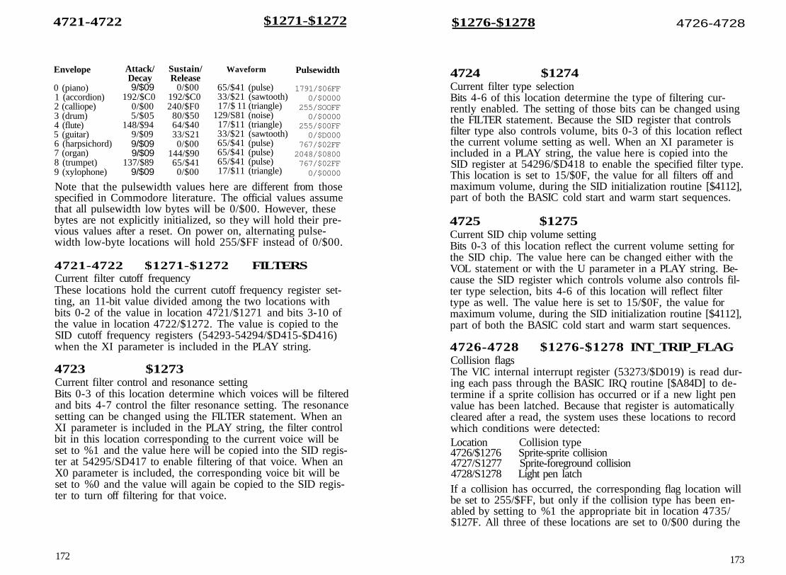
4721-4722 $1271-$1272
Envelope
0 (piano)1 (accordion)2 (calliope)3 (drum)4 (flute)5 (guitar)6 (harpsichord)7 (organ)8 (trumpet)9 (xylophone)
Attack/Decay9/$09
192/$C00/$005/$05
148/$949/$099/$099/$09
137/$899/$09
Sustain/Release
0/$00192/$C0240/$F0
80/$5064/$4033/S210/$00
144/$9065/$410/$00
Waveform
65/$41 (pulse)33/$21 (sawtooth)17/$ 11 (triangle)
129/S81 (noise)17/$11 (triangle)33/$21 (sawtooth)65/$41 (pulse)65/$41 (pulse)65/$41 (pulse)17/$11 (triangle)
Pulsewidth
1791/$06FF0/$0000
255/SOOFF0/$0000
255/$00FF0/$D000
767/$02FF2048/$0800767/$02FF0/$0000
Note that the pulsewidth values here are different from thosespecified in Commodore literature. The official values assumethat all pulsewidth low bytes will be 0/$00. However, thesebytes are not explicitly initialized, so they will hold their pre-vious values after a reset. On power on, alternating pulse-width low-byte locations will hold 255/$FF instead of 0/$00.
4721-4722 $1271-$1272 FILTERSCurrent filter cutoff frequencyThese locations hold the current cutoff frequency register set-ting, an 11-bit value divided among the two locations withbits 0-2 of the value in location 4721/$1271 and bits 3-10 ofthe value in location 4722/$1272. The value is copied to theSID cutoff frequency registers (54293-54294/$D415-$D416)when the XI parameter is included in the PLAY string.
4723 $1273Current filter control and resonance settingBits 0-3 of this location determine which voices will be filteredand bits 4-7 control the filter resonance setting. The resonancesetting can be changed using the FILTER statement. When anXI parameter is included in the PLAY string, the filter controlbit in this location corresponding to the current voice will beset to %1 and the value here will be copied into the SID regis-ter at 54295/SD417 to enable filtering of that voice. When anX0 parameter is included, the corresponding voice bit will beset to %0 and the value will again be copied to the SID regis-ter to turn off filtering for that voice.
172
$1276-$1278 4726-4728
4724 $1274Current filter type selectionBits 4-6 of this location determine the type of filtering cur-rently enabled. The setting of those bits can be changed usingthe FILTER statement. Because the SID register that controlsfilter type also controls volume, bits 0-3 of this location reflectthe current volume setting as well. When an XI parameter isincluded in a PLAY string, the value here is copied into theSID register at 54296/$D418 to enable the specified filter type.This location is set to 15/$0F, the value for all filters off andmaximum volume, during the SID initialization routine [$4112],part of both the BASIC cold start and warm start sequences.
4725 $1275Current SID chip volume settingBits 0-3 of this location reflect the current volume setting forthe SID chip. The value here can be changed either with theVOL statement or with the U parameter in a PLAY string. Be-cause the SID register which controls volume also controls fil-ter type selection, bits 4-6 of this location will reflect filtertype as well. The value here is set to 15/$0F, the value formaximum volume, during the SID initialization routine [$4112],part of both the BASIC cold start and warm start sequences.
4726-4728 $1276-$1278 INT_TRIP_FLAGCollision flagsThe VIC internal interrupt register (53273/$D019) is read dur-ing each pass through the BASIC IRQ routine [$A84D] to de-termine if a sprite collision has occurred or if a new light penvalue has been latched. Because that register is automaticallycleared after a read, the system uses these locations to recordwhich conditions were detected:Location Collision type4726/$1276 Sprite-sprite collision4727/S1277 Sprite-foreground collision4728/S1278 Light pen latchIf a collision has occurred, the corresponding flag location willbe set to 255/$FF, but only if the collision type has been en-abled by setting to %1 the appropriate bit in location 4735/$127F. All three of these locations are set to 0/$00 during the
173

4729-4734 $1279-$127E $1282-$12A2 4738-4770
SID initialization routine [$4112], part of both the BASIC coldstart and warm start sequences. A location set to 255/SFF willbe reset to 0/$00 after COLLISION processing in the GONEroutine [$4A9F].
4729-4734 $1279-$127E INT_ADRTarget line numbers for COLLISIONIf the trapping of sprite collisions or light pen latches is en-abled, a BASIC subroutine will be called (effectively a GOSUB)whenever one of the selected events occurs. These locationsare used to hold the number (in low-byte/high-byte integerformat) of the starting BASIC program line of the subroutineto be called. (The subroutine should end with a RETURNstatement.) The values here can be set with the COLLISIONstatement.
Low byte4729/$1279473O/$127A4731/$127B
High byte4732/$127C4733/$127D4734/S127E
Collision typesprite-spritesprite-foregroundlight pen
INTVAL4735 $127FCollision enable flagBits 0-2 of this location indicate the collision types for whichtrapping is currently enabled:Bit Collision type0 sprite-sprite1 sprite-foreground2 light pen
Trapping is enabled if the bit is set to % 1 . Enabling trappingwill allow the corresponding collision type to be recorded inthe flags at 4726-4728/$1276-$1278. Bits 3-7 of this locationare unused. The value here is reset to 0/$00 during the BASICcold-start sequence. This disables all COLLISION branching.
4736 $1280 COLTYPCollision type indexThe value here is used during the COLLISION routine [$7164]to hold an index into the line number table at 4729-4734/$1279-$127E.
4737 $1281 SOUND-VOICEVoice for current SOUND statementThe value in this location specifies which group of entries inthe following table should be loaded with the current SOUNDparameters. The value here is set to the value of the first pa-rameter in the SOUND statement, minus 1 to convert theBASIC voice number (1-3) into a SID voice number (0-2).
4738-4770 $1282-$12A2Table of SOUND statement settingsThese locations hold the current SOUND parameters for thethree SID chip voices:Parameter Voice 0 Voice 1 Voice 2Duration (low) 4738/$1282 4739/$1283 4740/$1284
(high) 4741/$1285 4742/$2286 4743/$1287Frequency (low) 4744/S1288 4745/$1289 4746/$128A
(high) 4747/5128B 4748/$128C 4749/$128DMinimum frequency (low) 4750/$128E 4751/$128F 4752/$1290
(high) 4753/$1291 4754/$I292 4755/$1293Step direction 4756/$1294 4757/$1295 4758/$1296Step size (low) 4759/51297 4760/51298 4761/$1299
(high) 4762/$129A 4763/$129B 4764/$129CCurrent frequency (low) 4765/$129D 4766/$129E 4767/$129F
(high) 4768/$12A0 4769/$12Al 4770/$12A2
Bit 7 of each of the duration high-byte values (locations4741-4743/$1285-$1287) is used to indicate whether anySOUND statement is active for the corresponding voice. If thebit is %0, the voice is assumed to have an active sound, andthe current frequency value for the voice will be copied intothe SID chip frequency registers during each pass through theBASIC IRQ routine [$A84D]. See Chapter 5 for a discussion ofthe other SOUND effects, such as frequency sweeps. Also dur-ing each pass through the interrupt routine, the duration valuefor each active voice will be decremented. When the value isdecremented below $0000, the high byte will roll over to255/$FF, setting bit 7 to % 1 , which marks the end of thesound. At this point the gate bit for the voice will be set to %0to turn off the sound.
Each of the duration high-byte locations will be set to255/$FF during the SID initialization routine, part of both theBASIC cold start and warm start sequences. This will turn off
174 175

4771-4776 $12A3-$12A8
SOUND output for all three voices. The values in these loca-tions are updated when the contents of 4771-4776/$ 12A3-$12A8are copied to the entries for the specified voice during executionof the SOUND statement [$71EC].
4771-4776 $12A3-$12A8Parameters for most recent SOUND statementThese locations are used to assemble the parameters for thecurrent SOUND statement. The SOUND statement must in-clude voice number, frequency, and duration parameters. Theremaining parameters are optional; if they are omitted, defaultvalues are supplied. The base frequency value is initialized tothe specified starting frequency. The locations and default val-ues are as follows:
Parameter Locations Default valueDuration 4771-4772/$12A3-$12A4Frequency 4773-4774/$12A5-$12A6Minimum frequency 4775-4776/$ 12A7-S12A8 0/$0000Step direction 4777/$12A9 0/$00 (sweep up)Step size 4778-4779/$ 12AA-S12AB 0/$0000 (no sweep)Base frequency 4780-4781/$12AC-$12ADPulsewidth 4782-4783/$12AE-$12AF 2048/S0800Waveform 4784/$12B0 2/$02 (pulse)
After all the parameters for a SOUND statement havebeen evaluated and assembled here, the values are transferredto the entries in the table at 4738-4770/$1282-$12A2 for thespecified voice. The base frequency value is used as the begin-ning current frequency value.
4785 $12B1 POT_TEMP_1Temporary storage for POT and PEN routinesThis location is used as temporary storage during the routinesto perform the BASIC functions POT [$824D1 and PEN[$82AE].
4786 $ 12B2 POT_TEMP_2Temporary storage for POT routineDuring execution of the POT function routine [$824D], thepotentiometer reading from the SID chip register is stored heretemporarily while the paddle buttons are being read.
176
$12F6-$12F9 4854-4857
4787-4790 $12B3-$12B6 WINDOW_TEMPSTemporary parameter storage for WINDOW statementWhen the WINDOW statement [$72CC] is executed, the pa-rameter values associated with the statement are stored inthese locations before the screen editor WINDOW routine[$C02D] is called to actually set the new window margins.Location Parameter4787/$12B3 left column4788/$12B4 top row4789/$12B5 right column4790/$12B6 bottom row
4791-4806 $12B7-$12C6Filename buffer for DOS support commandsThe routine which handles the BASIC 7.0 DOS support com-mands such as SCRATCH and RENAME copies the filenameportion of the command here temporarily while the remainderof the command is being processed. Once the command is setup, the filename here is copied into the DOS command bufferat 4352-4399/$1100-$112F.
4791-4853 $12B7-$12F5 SAVRAMSprite pattern storageThese locations are used during the SPRDEF statement routine[$7372] to hold the original sprite pattern while a sprite is be-ing defined. If the STOP key is pressed to cancel the currentmodifications, the pattern definition here will be restored tothe definition area for the sprite. The first 63 of these locationsare also used during the SPRSAV routine [$76EC] to hold thesprite pattern to be transferred to a string variable.
4854-4857 $12F6-$12F9Sprite pattern suffixDuring the SPRSAV routine [$76EC], these locations are ini-tialized with the pattern $17 $00 $14 $00. When a sprite pat-tern is saved in a string variable, these bytes are appended tothe sprite pattern in 4791-4853/$12B7-$12F5 before the datais transferred to the string pool. Two bytes are needed as thetag for the variable, but exactly what this four-byte pattern isintended to achieve is unclear.
177

4858 $12FA
4858 $12FA DEFMODSprite mode indicator for SPRDEFThis location is used during the SPRDEF statement routine[$7372] to hold a value indicating the mode of the sprite cur-rently being defined. A value here of 0/$00 indicates a stan-dard sprite, while a value of 128/$80 indicates a multicolorsprite.
4859 $ 12FB LINCNTSprite pattern line count for SPRDEFThis location is used during the SPRDEF statement routine[$7372] to hold the number of the vertical line (0-20) withinthe sprite pattern which is currently being defined.
4860 $12FC SPRITE_NUMBERSprite number for SPRDEFThis location is used during the SPRDEF statement routine[$7372] to hold the number (0-7) of the sprite currently beingdefined.
4861 $ 12FD IR9_WRAP_FLAGBASIC IRQ activity flagThis location is tested at the beginning of the BASIC IRQ ser-vice routine [$A84D]. If it contains any nonzero value, theroutine exits immediately. The location is initialized to 0/$00during the SID initialization routine [$4112]. The BASIC IRQroutine increments this location (to l/$01) when it begins, sothe test prevents the routine from being restarted if another in-terrupt occurs before the current pass is completed. The IRQroutine resets the value here to 0/$00 before exiting.
The BASIC portion of the IRQ sequence is responsible formoving sprites, detecting sprite collisions, and handling theBASIC sound statements. The routine maintains a number ofshadow locations which are copied into VIC and SID chiphardware registers during each interrupt. Sometimes you maywant to turn off these shadow locations to have direct accessto the hardware registers. One way to do that is to store somenonzero value in this location. While turning off the BASICIRQ routine will give you direct access to the hardware regis-ters, you should keep in mind that it will also effectively dis-able the BASIC statements MOVSPR, COLLISION, SOUNDand PLAY.
178
$13OO-$1BFF 4864-7167
4862-4863 $12FE-$12FF UnusedThese locations are not used by any 128 ROM routine.
Application Program Area4864-7167/$1300-$lBFFNone of the 2304 (2V4-K) locations in this area are used byany system ROM routines. Thus, this area is free for your ownprogramming uses—machine language routines, alternatescreens, and so on. Because this is the largest block of freeRAM protected from BASIC, the area is becoming extremelypopular with machine language programmers, much like thearea at 49152/$C000 in the Commodore 64. As a result, you'llprobably encounter instances where two programs you wantto use simultaneously will be incompatible because they resideat overlapping addresses within this range.
One thing this area cannot normally be used for is to holdadditional sprite patterns or custom character patterns. While thestandard ROM-based character sets are enabled, the VIC chipwill see character ROM at addresses 4096-8191/$1000-$lFFF.As a result, this RAM is not visible to the VIC chip and cannotbe used for sprite or character information. Sprite or characterpatterns can be stored here if the ROM-based characters aredisabled; refer to the entry for location l/$01 in Chapter 2 fordetails.
179

RAM UsageThe Commodore 128, as its name implies, has 128K of pri-mary RAM in two 64K blocks. Memory configurations are dis-cussed in detail in Chapter 1, but in general the 128 sees RAMfrom block 0 in even-numbered banks (0, 4, 8, 14) and RAMfrom block 1 in odd-numbered banks (1, 5, 9). A notable ex-ception is bank 15, where RAM from block 0 is seen. Anothersignificant exception is that in every bank the system normallysees RAM from block 0 in locations 2-1023/$0002-$03FF.(Remember that locations 0-l/$00-$01 are used for the pro-cessor's on-chip I/O port and are never seen as RAM.) Thismeans that the lowest IK of RAM in block 1 normally remainsinvisible and unused. As explained in Chapters 2 and 3, thecommon IK block and locations 1024-7167/$0400-$lBFF inblock 0 have special uses. Also, remember that MMU registers,rather than RAM or ROM, are seen at addresses 65280-65284/$FF00-$FF04 in every bank configuration.
Two pointers in page 10/$0A indicate the range of loca-tions in block 0 considered free RAM. Locations 2565-2566/$0A05-$0A06 point to the lowest free address, and locations2567-2568/$0A06-$0A07 point to one byte beyond the high-est free address. These pointers are initialized during theRAMTAS subroutine [$E093], part of the reset sequence, to7168/S1C00 and 65280/$FF00, respectively. The pointer val-ues can also be changed with the Kemal MEMTOP [SFF99]and MEMBOT [$FF9C] routines. However—unlike earlierCommodore computers—these pointers have no effect on therange of addresses used by BASIC and are not read by anyother Kernal or BASIC routine.
BASIC RAM UsageFor BASIC programming, the areas of RAM normally availablefor storage of programs and variables are locations 7168-65279/$1COO-$FEFF in block 0 and 1024-65279/$0400-$FEFF inblock 1. This is a total of 122,368 bytes of available RAMspace (illustrated in Figure 4-1). This explains why part of themessage you see when you turn on or reset the computer says122365 BYTES FREE. (The missing three bytes are to account
183

for the zero byte required by BASIC before the first programline and the two zero bytes used to mark the end of theprogram.)
Actually, it's a bit misleading to claim that many freebytes, since you can't write a BASIC program 120,000 byteslong. For BASIC, the free RAM is divided into two distinctsegments: the 58,112 bytes in block 0 for BASIC program textand the 64,256 bytes in block 1 for variables and strings. (Bycomparison, the Commodore 64 offers 38,911 bytes for pro-gram text and variables combined.)
As noted in Figure 4-1, there is one additional factorwhich affects the amount of memory available for programtext. When you use a GRAPHIC statement to set up a high-resolution screen, an additional 9K is reserved in block 0: IKat 7168-8191/$1COO-$1FFF for color information and 8K at8192-16383/$2000-$3FFF for the high-resolution-screen bit-map. In this case, the amount of RAM available for BASICprogram text is reduced to 48,896 bytes (locations 16384-65279/$4000-$FEFF in block 0). If a program is already in memorywhen the GRAPHIC statement is executed, the program ismoved upward in memory (the starting address will bechanged from 7169/$1CO1 to 16385/$4001) and relinked towork at the new addresses. Once a high-resolution memoryarea is established, it remains allocated until a GRAPHIC CLRstatement is executed, at which time the program text is moveddown to start at 7169/$1CO1 again.
Pointers in zero page and page 18/$ 12 are used to specifythe length of program text and variables. BASIC program textis assumed to begin at the address in block 0 specified in loca-tions 45-46/$2D-$2E. That pointer is initialized to 7169/$1CO1 during the BASIC cold start routine [$4023]. Unlike theCommodore 64, which sets its start-of-BASIC pointer accord-ing to the value in the system's start-of-free-memory pointer,the 128 sets the address value without regard for the value in2565-2566/$0A05-$0A06. Locations 4626-4627/$1212-$1213point to one byte beyond the highest available address inblock 0. That pointer is initialized during BASIC cold start to65280/$FF00, again without regard to the Kernal memorypointer value in 2567-2568/$0A07-$0A08. The actual endingaddress of the program text currently in memory is specifiedby the value in 4624-4625/$1210-$1211. That pointer is ini-tialized during the BASIC CLR routine [$51F8] to two bytes
184
Figure 4-1. BASIC RAM Usage
Bank 0

beyond the starting address in 45-46/$2D-$2E. An OUTOF MEMORY error occurs if the address in 4624-4625/$1210-$1211 reaches the value in 4626-4627/ $1212-$1213.The ending address pointer is set after a BASIC LOAD [$912C],and the BASIC SAVE routine [$9112] uses the values in thestarting and ending address pointers as the starting and end-ing address for the block of memory to be saved.
The address in the pointer at locations 47-48/$2F-$30marks the start of scalar (nonarray) variables in bank I. Thepointer is initialized to 1024/$0400 during the BASIC coldstart routine. A pointer at 49-50/$31-$32 marks the end ofscalar variables and the beginning of arrays; another pointer at51-52/$33-$34 marks the end of arrays and the beginning offree memory in block 1. Both of these pointers are reset to thevalue in 47-48/$2F-$30 during the BASIC CLR routine. Thepointer at 57-58/$39-$3A holds an address which is one bytebeyond the highest address of free memory in block 1. It isinitialized during BASIC cold start to point to 65280/$FF00.The free memory in block 1 is used to hold strings of alltypes—constants, variables, and arrays. The string pool startsat the top of free memory and is filled downward toward thebottom of free memory indicated in 51-52/$33-$34. Thepointer at 53-54/$35-$36 marks the current address of thebottom of the string pool. That pointer is reset to the value in57-58/$39-$3A by the BASIC CLR routine. An OUT OFMEMORY error occurs when the value in 53-54/$35-$36reaches the value in 51-52/$33-$34.
Reserving RAMThere are occasions when you will want to divert an area ofRAM from its normal usage. For example, you may need to setaside space for a machine language routine, an alternatescreen display, or a data buffer. For machine language (ML)programming, you can use any area of RAM if you are willingto learn the intricacies of the 128's banking scheme. Other-wise, it's best to restrict your programming to certain knownareas. For a machine language routine to be used in conjunc-tion with a BASIC program, you'll need to select an areawhich BASIC doesn't normally use, or to take away somememory that otherwise would be used for program text orvariable storage. As noted in Chapter 3, locations 4864-7167/$13OO-$1BFF are currently unused (even though they are
186
called "reserved" in Commodore literature). This 2304-bytearea is the largest unused area of protected RAM in the 128,and it is becoming extremely popular with 128 ML program-mers—much like the $C000 block in the Commodore 64. Youcan expect to see many ML programs using this area.
Other, shorter blocks are also available if certain BASICfeatures are not used. If tape is not used, the 256 bytes at2816-3071/$0B00-$0BFF are available. However, unlike otherfree blocks, this page may be overwritten during a reset be-cause disk boot sectors are read into this area. Thus, the time-honored Commodore tradition of using the cassette buffer forshort ML routines is less suitable in the 128. (It's annoying tohave to reload your routine after each reset.) If your programdoesn't use RS-232 communications, the two RS-232 buffers at3072-3583/$0C00-$0DFF provide a 512-byte workspace. Thisis probably the best area for short ML routines that you wishto use in conjunction with BASIC. (Unlike the cassette buffer,this area survives reset intact.) If your program does not usesprites, the 512-byte sprite definition area at 3584-4095/$0E00-$0FFF is also available. Of course, if your program usesneither tape nor RS-232 nor sprites, you can use the full 1280bytes at 2816-4095/$0B00-$0FFF or any subsection thereof.
To use a large ML program in conjunction with BASIC,there is an easy way to reserve over UK of protected RAM.However, this technique works only if neither the BASIC northe ML program requires high-resolution graphics. The trick isto use the BASIC GRAPHIC statement to set aside a high-resolution screen area at 7168-16383/$lC00-$3FFF. As men-tioned above, this area remains allocated until a GRAPHICCLR statement is executed. Simply begin your BASIC programwith a line like GRAPHIC 1:GRAPHIC 0 (or GRAPHIC1:GRAPHIC 5 if you want to use the 80-column display).Then BLOAD the machine language program into the reservedarea. In addition to the 9K screen area, you can also use thecontiguous unused area just below, at 4864-7167/$1300-$lBFF.If you want to use a machine language program in conjunctionwith BASIC and high-resolution graphics, you'll have to resortto bank-switching techniques if the program is too large to fitin the unused area at 4864/$1300.
It's possible to reserve space above or below either theBASIC or variable/string areas. To reserve space below theBASIC program text, increase the value in the start-of-BASIC
187

pointer at 45-46/$2D-$2E by the number of bytes you wantto reserve. (To reserve an even number of 256-byte pages, youneed only change the value in 46/$2E.) Two other steps arealso necessary: BASIC requires a zero byte below the first lo-cation in its program text space, and a NEW operation is re-quired to reset other important memory pointers. For example,to reserve three pages (768 bytes) below the normal start ofBASIC, you would use a statement like this:POKE 46,31:POKE 31*256,0:NEW
After this statement is executed, the area at 7168-7935/$1COO-$1EFF is protected from BASIC until the next time theBASIC cold start routine is performed (normally during thenext reset sequence). The pointer value is unaffected byRUN/STOP-RESTORE. This technique is less useful when ahigh-resolution screen area is allocated. In that case, the startof BASIC is moved to 16384/$4000. The technique for reserv-ing space at the start of BASIC still works, but the reservedmemory will lie above 16383/$3FFF, which is the highest ad-dress seen as RAM in bank 15—the bank in which KernalROM is visible and to which BASIC defaults. Thus, a routineabove that boundary will be invisible unless you tinker withthe MMU configuration register.
Space can be reserved at the top of the BASIC programarea by reducing the value in the pointer at 4626-4627/$1212—$1213 by the desired number of bytes. (Again, if youwish to reserve an even number of 256-byte pages, you cansimply reduce the value in 4627/$l213.) No additional stepsare required other than changing the pointer value. This tech-nique was often used in the Commodore 64 to reserve spacefor machine language routines; its usefulness is more limitedin the 128 because of the 16384/$4000 boundary of RAM visi-ble in bank 15, which was mentioned above. To easily use thereserved area for an ML routine in conjunction with BASIC,the top of memory must be lowered sufficiently to make atleast a portion of the reserved area appear below the bound-ary of RAM visible in bank 15; this dramatically reduces theamount of memory available for program text. It's not evenpossible when a high-resolution screen area is allocated. Thetechnique can, however, be useful for setting aside an area inblock 0 for a buffer, a reserved area of memory for datastorage.
188
You can also reserve space in block 1, either above or be-low the variable/string area. To reserve space below variables,add a value corresponding to the number of bytes to be re-served to the address in the pointer at 47-48/$2F-$30, (Aswith the other pointers, you can simply increase the value in48/$30 if you are reserving an even number of 256-bytepages.) This step must be followed by a BASIC CLR statementto reset other variable pointers, so it should be performedearly in the program (CLR erases all variable values). The fol-lowing line reserves an additional IK at the bottom of variablespace, locations 1024-2047/$0400-$07FF in block 1:100 POKE 48,8:CLROnce established, the reserved area will remain intact until thenext time the BASIC cold start routine is executed, normallyat the next reset. The setting is unaffected by RUN/STOP-RESTORE.
Since this reserved RAM is in block 1, it can't be used forML routines as easily as the RAM from block 0. There is nostandard bank configuration that makes BASIC and KernalROM visible in conjunction with block 1 RAM. Of course, it ispossible to access Kernal or BASIC routines indirectly by usingthe JSRFAR or JMPFAR routine. One use for a reserved area inblock 1 would be for an alternate 40-column screen. See theentry for the MMU RAM configuration register (54535/$D506)information on using block 1 for VIC-II screen memory.
To reserve space above strings, subtract a value cor-responding to the number of bytes to be reserved from the ad-dress in the pointer at 57-58/$39-$3A. (As with the otherpointers, you can simply increase the value in 58/$3A if youare reserving an even number of 256-byte pages.) This stepmust also be followed by a BASIC CLR statement to resetother string pointers, so it should be performed early in theprogram (CLR erases all variable values). The following linereserves 31K at the top of string space, locations32768-65279/$8000-$FEFF in block 1:100 POKE 58,128:CLR
Once established, the reserved area will remain intact until thenext time the BASIC cold start routine is executed—normallyat the next reset. The setting is unaffected by RUN/STOP-RESTORE. As mentioned above, this area can't be easily usedfor machine language routines since it is in block 1. One ap-
189

propriate use for a reserved area here would be for a databuffer—to hold downloaded text in a telecommunications pro-gram, for example.
Using ML Without BASICYou have several options when using ML programs alone,without BASIC. The simplest, if your program is less than 9K(9216 bytes) long, is to leave the system in its default bank 15configuration and use the visible area of block 0 RAM at7168-16383/$lC00-$3FFF. (If you need a few more bytes,you can stretch the start of the program down to the bottomof the reserved area at 4864/$1300.) With this setup, you havefull access to the I/O chip registers and all the routines inBASIC and Kernal ROM.
If you need more space, but still want access to Kernalroutines, you can change the settings of bits 1-3 of the MMUconfiguration register to switch out BASIC ROM. In this case,you'll have access to over 43K of contiguous RAM, locations4864-49151/$1300-$BFFF. If you want to use a high-resolutionscreen in conjunction with your ML routine, it's easiest to setup the screen in its normal location (7168-16383/$1COO-$3FFF).This means that—if your program is too long to fit below thescreen areas—you'll need to switch out BASIC to have someRAM visible with Kernal ROM. (You could still use the KernalJSRFAR routine to access BASIC routines—if you wanted touse some of the graphics drawing routines, for example.)
Although it is possible to set up a custom MMU configu-ration that makes block 1 RAM visible with either BASIC orKernal ROM (or both), there's rarely a need for such gyrations.It's usually easiest to locate your executable machine languagein block 0 and use block 1 for data storage.
Several obscure techniques are available to squeeze a fewmore bytes out of the 128. For example, you can gain access tothe lowest IK of block 1 RAM, which is normally covered bythe common area from block 0, by changing the value in theMMU RAM configuration register (54534/$D506). See the dis-cussion of the MMU in Chapter 8 for details.
Page 255/$FFThe highest page of memory, locations 65280-65535/$FFO0-$FFFF, in each RAM block is normally unused byBASIC and contains a few bytes of free RAM as well as some
190
important routines and vectors. The MMU configuration andload configuration registers always appear in the lower fivebytes of this area, locations 65280-65284/$FF00-$FF04. Theyshould never be disturbed unless you know the effect of thevalues you are storing there (see Chapter 8 for more infor-mation on the MMU). You should also exercise care whenchanging the contents of locations 65285-65348/$FF05-$FF44in either RAM block, as these areas contain copies of the inter-rupt and reset handling routines. (These areas are initializedby the Kernal RESET routine [$E000].) If an interrupt or resetoccurs while the system is configured for a bank where KernalROM is not visible—bank 0 or 1, for example—a crash willoccur if the area in the visible RAM block does not contain aroutine to redirect the reset or interrupt to a proper handlingroutine. See the entries for these addresses in Chapter 9,"Kernal ROM," for more information.
Free space in this page includes the 181 bytes at locations65349-65529/$FF45-$FFF9 in block 0 and the 176 bytes at65349-65524/$FF45-$FFF4 in block 1. However, locations65488-65519/$FFD0-$FFEF in block 0 will be overwrittenwhenever the computer is reset. As mentioned in Chapter 1,the Z80 microprocessor has control briefly after a reset orwhen the computer is first powered on. The initialization stepsperformed by the Z80 include copying two routines into block0 RAM. One, at 65488-65503/$FFD0-$FFDF, is an 8502 ma-chine language routine to surrender control to the Z80; theother, at 65504-65519/$FFE0-$FFEF, is a Z80 machine lan-guage routine to surrender control to the 8502. These routineshave no use in 128 mode—they can be used only in CP/Mmode—but they are recopied to block 0 during each reset.{Actually, there is one situation where disturbing these routinescan cause a problem. If you overwrite the routine at 65488/$FFD0 and then attempt to start CP/M with a BASIC BOOTcommand, the system will crash. The machine language in theCP/M boot sector expects that routine to be intact.)
Locations 65525-65529/$KFF5-$FFF9 in block 1 have aspecial use. The first three bytes, locations 65525-65527/$FFF5-$FFF7, are an initialization signature; after the KernalRESET routine [$E000] has been performed at least once, theselocations will contain the character codes for the letters CBM.
191

As long as the signature locations contain these codes, the ini-tialization test subroutine will take an indirect jump to the ad-dress specified in locations 65528-65529/$FFF8-$FFF9, calledthe system vector or soft reset vector. This vector normallypoints to 57892/$E224 in Kernal ROM, a routine that doesnothing more than reinitialize the signature and vector. Youcan change the vector to point to a routine of your own to addadditional steps to the reset sequence or to initiate an entirelynew reset sequence. One restriction applies: The routine youspecify in the vector must be visible in the bank 15 configura-tion since that is how the system is set up when the jumpthrough the vector is taken.
When tapping into the RESET routine, you need to beaware of what has happened before the vector jump is takenand what hasn't happened yet. Before entering the subroutinethat takes the jump through the vector, the RESET routine[$E000] resets the stack pointer to the top of the stack, config-ures the system for bank 15, resets the other MMU registers totheir default values, and recopies the common routines to65285-65348/$FF05-$FF44, 674-763/$02A2-$02FB, and1008-1020/$03F0-$03FC. However, the initialization routinesIOINIT, RAMTAS, RESTOR, and CINT are normally calledafter the return from the jump. This means that you can't usethe vector diversion to change default indirect vector settingsor to alter screen parameters if your routine ends with RTS toreturn to the normal reset sequence. It also means that whenyou use the vector to substitute your own reset sequence, youmay need to call one or more of these subroutines to completesystem initialization. At least the IOINIT routine [$E109] orsome equivalent initialization routine is necessary, since thereset signal generated by pressing the RESET button also re-sets the VIC and VDC (8563) video chips, clearing all chipregisters to zero. IOINIT initializes the video chip registers totheir standard settings.
One interesting use of this vector is to make a machinelanguage program unstoppable by anything short of turningoff the computer. To accomplish this, change the vector topoint to the initialization routine of the program to be madeunstoppable. That initialization step should include calls to at
192
least the IOINIT and CINT routines, and it should also disableRUN/STOP-RESTORE by redirecting the NMI vector. Here isa short example:
ocoo0C020C04OC060C08OCOAOCODOCOF0C110C130C160C180C1A0C1B0C1E0C200C230C25OC280C2B0C2E0C300C330C350C380C39
LDASTALDASTALDASTALDALDXLDYJSRLDALDXINYJSRLDASTALDASTAJSRJSRLDXLDABEQJSRINXBNE
#$F8$C3#$FF$C4#$C3$02B9#$28#$01#$00$FF77#$0C#$01
$FF77#$33$0318#$FF$0319$FF84$cooo#$00$0C40,X$0C2E$FFD2
$0C30;Text for message>0C40>0C48>0C50
49 2042 4545 44
43 4120 53
;Use Kernal INDSTA routine tochange system reset vector
; in bank 1 to point to the; routine at $0C28
;Change the INMI indirect vector; to point to the interrupt return; routine (disables RUN/STOP-; RESTORE);Kernal IOINIT routine;Kernal CINT routine;Loop to print message repeatedly; text at $0C40
4E 27 54 2054 4F 50 50
21 0D0DO0Use J F0C00 {from the monitor) or BANK 15:SYS 3072
(from BASIC) to set the new pointer values and start the rou-tine. Once started, it cannot be stopped with either reset orRUN/STOP-RESTORE. Obviously, you should make surethat your ML program is fully debugged—and be sure thatyou have a backup copy, just in case it isn't—before you usethis technique to make the program unstoppable.
The highest six addresses in each RAM block, locations65530-65535/$FFFA-$FFFF, contain copies of the processor
193

reset and interrupt vectors. This area is initialized during thereset sequence, and, like the handling routines to which thesevectors point, these vector addresses should be changed withcare. The system will crash if a RAM vector does not containthe address of a valid handling routine when an interrupt orreset occurs while that block is visible. See the entries forthese addresses in Chapter 9 for more information on the pro-cessor vectors.
194

BASIC ROM
The Commodore 128's BASIC 7.0 occupies the 28K of ROMbetween 16384-45055/$4000-$AFFF. That represents signifi-cant growth from the BASIC 2.0 of the Commodore 64, whichfilled only about 9K. The expansion is the result of the addi-tion of a variety of graphics, sound, and sprite statements, aswell as enhanced commands for disk operations. BecauseBASIC is so large, it's not practical to provide a detailed de-scription of every routine—that would fill another book. In-stead, the entry points to most of BASIC'S important routinesare listed, with short explanations of what the target routines do.
Adding to BASICEven with all the added features of BASIC 7.0, you may findit lacking and wish to modify BASIC to add new commands.One common way to do this in the Commodore 64 is to copyBASIC ROM into RAM, then modify and use the RAM-basedversion. This scheme can't be used on the 128, even though itdoes have RAM under BASIC ROM like the 64. While it's pos-sible to copy BASIC into ROM, there's no easy way to keep aRAM-based version of BASIC executing in RAM. The bank-switching routines in 128 BASIC ROM keep the system con-figured for banks 14 or 15, where BASIC ROM is visible,while BASIC routines are being executed.
The formal method of adding new statements or functionsis to tap into the indirect vectors at 780-785/$030C-$0311and 764-765/$02FC-$02FD. This allows you to add newstatements or functions that use the two-byte extended tokens.Currently, extended statement tokens 39-255/$27-$FF andextended function tokens ll-255/$0B-$FF are unused andthus available for your additional keywords.
Three separate steps are required to add a new keyword.You must provide for it to be tokenized, detokenized (listed),and executed. The indirect vector at 780-781/$030C-$030Dlets you patch into the CRUNCH routine to tokenize your newextended token keywords. The vector at 782-783/$030E-$030F lets you patch into the IQPLOP routine todetokenize these new keywords when a line containing a new
197

keyword is listed. The other two vectors allow you to patchinto the statement and function execution routines to providefor the handling of the new keywords (784-785/$0310-$0311for statements and 764-765/$02FC-$02FD for functions). Thefollowing example shows the addition of a statement and afunction. The statement, STORE, can be used to store valuesin the VDC chip internal registers (see Chapter 8 for details ofthe VDC chip). The format of the statement is STORE register,value. The register parameter is the VDC register number(0-36) and the value parameter is the value (0-255) to bestored in that register. The function, RAD, converts an anglevalue from degrees to radians, the system used in BASIC func-tions. The format for the function is KAD(angle), where angleis the angle value in degrees. Since this is a function, it mustbe used on the right side of an operation, as in A = RAD(45).
;Redirect ICRNCH2 vector to $1629 to; tokenize new keywords
;Redirect IQPLOP2 vector to $165A to; list new keywords
;Redirect IGONE2 vector to $167B to; handle new statement
;Redirect ESC_FN vector to $16A2 to; handle new (unction
;Tokenize new keywords.Stash current character;Search for keyword in table at $1650
;If no match found, try other table;Convert index (with bit 7 set) to token (39/$27);Set flag for extended statement token
.Search for keyword in table at $1656
;Exit if no match found.Convert index (with bit 7 set) to token (11/$OB);Set flag for extended function token
1600160216051607160A160C160F1611161416161619161C161E1620162316251628
1629162B162D162F1632163416361638163A163C163E164116431645
LDASTALDASTALDASTALDASTALDASTALDASTALDASTALDASTARTS
STALDYLDAJSRBCCADCLDXBEQLDYLDAJSRBCCADCLDX
#$29$030C#$16$030D#$5AS030E#$16$030F#$7B$0310#$16$0311#$A2$02FC#$16$02FD
$02#$50#$16543E2$163A#$A6#$00$1647#$56#$16$43E2$164A#$8A#$FF
198
1647 CLC1648 BCC $164D ;Exit with carry clear if keyword found164A SEC164B LDA $02 ;Restore text character164D JMP $4321 .Return to ICRNCH routine>1650 53 54 4F 52 C5 00 ;STORE>1656 52 41 C4 00 ;RAD
;List (detokenize) new keywords165A CPX #$00 ;Was this statement or token?165C BNE S166C165E CMP #$28 ;Was statement token less than 40?1660 BCS $16781662 LDY #$50 ;Use table entry at $1650 to list1664 LDA #$161666 STY $241668 STA $25166A BCC $1678166C CMP #$0C ;Was function token less than 12?166E BCS $16781670 LDY #$56 ;Use table entry at $1656 to list1672 LDA #$161674 STY $241676 STA $251678 JMP S51CD ;Return to IQPLOP routine
; Handle execution of statement167B CMP #$28 ;Was statement token less than 40?167D BCS $1685167F LDA #$16 ;Put address of execution routine - 1 on stack1681 PHA ; (execution routine is at $1866)1682 LDA #$871684 PHA1685 JMP $4BA9
; STORE routine1688 JSR $8803 ;Evaluate register number and value parameters168B TXA ;Move value lo accumulator168C LDY $17 ;High byte of register number should be zero168E BNE $169D1690 LDX $16 ;Low byte (in X) should be less than 371692 CPX #$251694 BCS $169D1696 STY $FF00 ;Set for bank 15 so VDC chip is visible1699 JSR $CDCC;Use screen editor routine169C RTS169D LDX #$0E ;Illegal quantity error if incorrect value supplied169F JMP ($0300)
;RAD routine16A2 CMP #$0C ;Was token less than 12?16A4 BCS $16B416A6 JSR $7956 ;Check that parameter ended with a closing
parenthesis16A9 LDA #$B5 ;Load value from $16B5 into FAC2
199

16AB16AD16B016B316B4>16B5
LDYJSRJSRCLCRTS7B OE
#$16SAF5D$AF21 ^Multiply by argument in FAC1
FA 35 12 ;Floating point value for TT/180
An alternate method of adding new statements to BASICinvolves creating intentional errors. To use this scheme, yournew keyword must consist of an existing keyword precededby a letter (or another keyword)—LLIST or COPYCHAR, forexample. A syntax error will occur when the new keyword isencountered, but you can use the IERROR indirect vector(768-769/$0300-$0301) to trap the error and process the key-word. The advantage of this technique is that you don't haveto worry about tokenizing or detokenizing the new keyword.The following example program illustrates the technique. Itsupports a new statement, VPOKE, which performs like theSTORE statement in the example above. Use VPOKE register,value to store a value in a VDC chip register. After a SYS 4864to patch in this routine, VPOKE can be used in either programor immediate mode, just like any other keyword.
;Redirect IERROR vector to $130B
;Was this a SYNTAX error?
;If §o, did it occur at a POKE token?
;Calculate pointer to character; immediately before the POKE token; (If the keyword uses a two-byte; extended token, you must back up; two positions instead of one.)
;Retrieve character before token;Was it a V?;If so, branch to handle VPOKE;Process all other errors normally;Move CHRGET pointer beyond token.Evaluate parameters following VPOKE;Move value parameter to accumulator;Check that register parameter is; less than 37
1300130213051307130A130B130D130F13111313131513171319131B131D131F1322132413261329132C132F13301322
LDASTALDASTARTSCPXBNECMPBNELDASBCSTALDASBCSTAJSRCMPBEQJMPJSRJSRTXALDYBNE
#$0B$0300#$13$0301
#$0B$1326#$97$1326$3D#$01$26$3E#$00$27$03C0#$56$1329$4D3F$0380$8803
$17$133A
200
$4006 16390
133413361338133A133C133E13411344
LDXCPXBCCLDXBNESTYJSRJMP
$16#$25$133E#$0E$1326$FFO0
(target register number in X)
;If register number is too large,; exit with ILLEGAL QUANTITY error;Configure for bank 15 (Y contains $00)
$CDCC;Use screen editor register setup routine$AF90 ;Continue processing program text
The BASIC Jump TableOne new feature of BASIC 7.0 that will be very valuable tomachine language programmers is the jump table at44800-44967/$AFOO-$AEA7. Many of the most useful BASICroutines now have static entry points like those the Kernaljump table provides for Kernal routines. Wherever possible,you should use the jump table entry into the routine to main-tain compatibility in the event that BASIC ROM is revised.
BASIC Entry Vectors16384 $4000 JHARD-RESETBASIC cold-start entry point; jumps to 16419/$4023, the ad-dress of the routine which performs a complete initializationof BASIC. This is the normal entry point following a systemreset.
16387 $4003 JSOFT_RESETBASIC warm-start entry point; jumps to 16393/$4009, the ad-dress of the routine which reinitializes BASIC and Kernal vec-tors and screen editor vectors and variables. This is the normalentry point during a RUN/STOP-RE STORE NMI interrupt.
16390 $4006 JBASIC-IR9BASIC IRQ entry point; jumps to 43085/$A84D, the addressof the routine which handles the BASIC portion of the systemIRQ interrupt sequence. The target routine supports spritemovement, sprite collision detection, light pen reading, andthe BASIC music statements. This is the normal entry pointduring the system IRQ service routine.
201

16393 $4009 $43B0 17328
16393 $4009 SOFT-RESETPerforms a warm start of BASICThis routine is the normal final step of the RUN/STOP-RESTORE sequence. It resets the SID registers and sound loca-tions, and calls the routine at 16781/$418D to stop spritemovement. However, it does not reinitialize the BASIC vectorsor pointers.
16416 $4020 UnusedThree unused bytes filled with the value 255/$FR
HARD_RESET16419 $4023Performs a cold start of BASICThis routine is the normal final step of the reset sequence. Itperforms a complete initialization of BASIC, including reset-ting all vectors, pointers, and working storage locations totheir default values. This routine also includes a call to theKernal PHOENIX routine [$FF56], which will start any func-tion ROMs that may be present, or boot a disk if one is in thedrive,
16453 $4045Initializes BASIC painters and constantsThis is the main initalization routine of the cold-start se-quence. It is responsible for setting all RAM working storagelocations for BASIC to their default values.
16658 $4112Initializes SID registers and sound routine locationsThis routine sets all SID chip registers to 0/$00 and initializesall locations associated with the SOUND and PLAYstatements.
16762 $417AInitializes MMU preconfiguration registers
16781 $ 4 1 8 DInitializes sprite speed and direction tableThis routine copies a 0/$00 into the speed control byte foreach entry in the sprite movement table at 4478/$117E, effec-tively halting all sprite motion.
16795 $419BDisplays the power-on messageThis routine displays the text from the following area of ROM,Note that the free memory figure is part of the ROM message,and may not reflect the actual amount of memory available toBASIC.
16827 $4IBBText for power-on message{CLR}
COMMODORE BASIC V7.0 122365 BYTES FREE(O1985 COMMODORE ELECTRONICS, LTD.
(O1977 MICROSOFT CORP.ALL RIGHTS RESERVED
16977 $4251Initializes BASIC indirect vectorsThis routine copies the BASIC indirect vectors from the fol-lowing table to locations 768-785/$0300-$0311, and initial-izes the vector at 764-765/$02FC-$02FD.
16999 $4267Table of default vector valuesThis area contains the default addresses copied into the page 3indirect vectors by the routine at 16977/$4251.
17017 $4279Text for character retrieval routinesThis area contains the code for CHRGET and the other page 3character retrieval subroutines. The routines are copied intoRAM.
17102 $42CEAssorted character retrieval subroutines
17162 $430 A CRUNCHTokenizes keywords in lines of BASIC program text
17328 S43B0Handles extended tokens
202 203

17356 $43CC
17356 $43CCDeletes a character in the input buffer
17378 $43E2Searches keyword tables for match
17431 $4417BASIC keyword tablesThe following table holds the BASIC 7.0 keywords in tokennumber order. Bit 7 of the last character of each keyword willbe set to %1 to indicate the end of the keyword.
$4609 17929
Token128/S80129/S81130/$82131/$83132/$84133/$85134/$86135/$87136/$88137/S89138/$8A139/S8B140/S8C141/$8D142/$8E143/$8F144/$90145/$91146/$92147/$93148/$94149/$95150/$96151/$97152/$98153/$99154/$9A155/$9B156/S9C157/$9D158/S9E159/S9F
KeywordENDFORNEXTDATAINPUT#INPUTDIMREADLETGOTORUNIFRESTOREGOSUBRETURNREMSTOPONWAITLOADSAVEVERIFYDEFPOKEPRINT#PRINTCONTLISTCLRCMDSYSOPEN
Token160/$A0161/$A1162/$A2163/$ A3164/$A4165/$A5166/$A6167/SA7168/SA8169/SA9170/$AA171/$AB172/$ AC173/$AD174/JAE175/$AF176/$B0177/SB1178/$B2179/$B3180/$B4181/$B5182/$B6183/$B7184/$B8185/SB9186/$8A187/$BB188/SBC189/$BD190/$BE191/$BF
KeywordCLOSEGETNEWTAB(TOFNSPC(THENNOTSTEP+-*/tANDOR>—<SGNINTABSUSRFREPOSSQRRNDLOGEXPCOSSIN
Token Keyword192/$C0 TAN193/$C1 ATN194/$C2 PEEK195/$C3 LEN196/$C4 STR$197/$C5 VAL198/$C6 ASC199/$C7 CHR$200/$C8 LEFT$201/$C9 RIGHT$202/$CA MID$203/$CB GO204/$CC RGR205/$CD RCLK206/$CE function token extender207/$CF JOY208/$D0 RDOT2O9/$D1 DEC210/SD2 HEX$211/$D3 ERR$212/$D4 INSTR213/$D5 ELSE214/$D6 RESUME215/$D7 TRAP216/$D8 TRON217/$D9 TROFF218/$DA SOUND219/$DB VOL220/SDC AUTO221/$DD PUDEF222/SDE GRAPHIC223/$DF PAINT
Token224/$E0225/$E1226/$E2227/$E3228/$E4229/$E5230/$E6231/$E7232/$E8233/$E9234/$EA235/$EB236/$EC237/$ED238/$EE239/$EF240/$F0241/$F1242/$F2243/$F3244/$F4245/$F5246/$F6247/$F7248/$F8249/$F9250/$FA251/$FB252/$FC253/$FD254/$FE
KeywordCHARBOXCIRCLEGSHAPESSHAPEDRAWLOCATECOLORSCNCLRSCALEHELPDOLOOPEXITDIRECTORYDSAVEDLOADHEADERSCRATCHCOLLECTCOPYRENAMEBACKUPDELETERENUMBERKEYMONITORUSINGUNTILWHILEstatement token extender
204
17929 $4609Table of extended token statementsBASIC 7,0 has too many keywords to have a one-byte tokenfor each. Additional statements use a two-byte token wherethe first byte is always 254/$FE. This table holds the extendedtoken statement keywords in order of the second byte of thetoken, like the standard keywords, bit 7 of the last characterof each keyword will be set to % 1 .
205

18121 $46C9
Token2/$023/$O34/$045/$056/$067/$078/$089/$0910/SOA11/$OB12/$0C13/$0D14/$0E15/SOF16/$1017/S1118/$1219/$1320/$14
KeywordBANKFILTERPLAYTEMPOMOVSPRSPRITESPRCOLORRREGENVELOPESLEEPCATALOGDOPENAPPENDDCLOSEBSAVEBLOADRECORDCON CATDVERIFY
Token21/$1522/$1623/$1724/$1825/$1926/$lA27/S1B28/$lC29/$lD3O/$1E31/$1F32/$2033/$2134/$2235/$2336/$2437/$2538/$26
KeywordDCLEARSPRSAVCOLLISIONBEGINBENDWINDOWBOOTWIDTHSPRDEFQUITSTASH(no keyword for this token)FETCH{no keyword for this token)SWAPOFFFASTSLOW
18121 $46C9Table of extended token functionsBASIC 7.0 has too many keywords to have a one-byte tokenfor each. Additional functions use a two-byte token where thefirst byte is always 206/$CE. This table holds the extendedtoken function keywords in order of the second byte of thetoken. Like the standard keywords, bit 7 of the last characterof each entry is set to % 1 .Token Keyword2/$02 POT3/$03 BUMP4/$04 PEN5/$05 RSPPOS6/$06 RSPRITE7/$07 RSPCOLOR8/$08 XOR9/$09 RWINDOW10/$0A POINTER
18172 $46FCTable of statement dispatch addressesThis area holds the address of the routines to execute tokens128-162/$80-$A2. Because of the way statement execution is
206
$4828 18472
handled, the values here are actually one less than the addressof the target routine. See Appendix F for a list of keyword exe-cution addresses.
18242 $4742Table of statement dispatch addressesThis area holds the address of the routines to execute tokens213-250/$D5-$FA. Because of the way statement execution ishandled, the values here are actually one less than the addressof the target routine. See Appendix F for a list of keyword exe-cution addresses.
18172 $46FCTable of statement dispatch addressesThis area holds the address of the routines to execute ex-tended statement tokens 2-38/$02-$26. Because of the waystatement execution is handled, the values here are actuallyone less than the address of the target routine. See AppendixF for a list of keyword execution addresses.
18317 $478DTable of function dispatch addressesThis area holds the address of the routines to execute tokens180-211/$B4-$D3. See Appendix F for a list of keyword exe-cution addresses.
18454 $4816Table of function dispatch addressesThis area holds the address of the routines to execute ex-tended function tokens 2-10/$02-$0A. See Appendix F for alist of keyword execution addresses.
18472 $4828Table of operator priorities and dispatch addressesEach mathematical operator such as + ,—,*, and / has athree-byte entry in this table. The first byte is the priority ofthe operator for expression evaluation and the next two arethe address of the routine to perform the specified operation.
207

18502 $4846
18502 $4846Prints unimplemented command messageBASIC 7.0 contains two unused keywords, QUIT and OFF.Either of those will use this routine to print the UNIMPLE-MENTED COMMAND error message.
18507 $484BTable of BASIC error messagesThis area holds text for the BASIC error messages in errornumber order. Bit 7 in the last character of each message willbe set to %1 to mark the end of the message.
Error number1/S012/$023/$034/$045/$056/$067/$078/$089/$0910/$0A11/$OB12/$0C13/$0D14/$0E15/$0F16/flO17/S1118/$1219/$1320/$1421/$1522/$1623/$1724/$1825/$1926/$lA27/$lB28/$lC29/$lD30/$ IE31/$1F
Error messageTOO MANY FILESFILE OPENRLE NOT OPENFILE NOT FOUNDDEVICE NOT PRESENTNOT INPUT RLENOT OUTPUT FILEMISSING FILE NAMEILLEGAL DEVICE NUMBERNEXT WITHOUT FORSYNTAXRETURN WITHOUT GOSUBOUT OF DATAILLEGAL QUANTITYOVERFLOWOUT OF MEMORYUNDEF'D STATEMENTBAD SUBSCRIPTREDIM'D ARRAYDIVISION BY ZEROILLEGAL DIRECTTYPE MISMATCHSTRING TOO LONGFILE DATAFORMULA TOO COMPLEXCANT CONTINUEUNDEF'D FUNCTIONVERIFYLOADBREAKCANT RESUME
$4C83 19587
Error number32/$2033/$2134/$2235/$2336/$2437/$2538/$2639/$2740/$2841/$29
Error messageLOOP NOT FOUNDLOOP WITHOUT DODIRECT MODE ONLYNO GRAPHICS AREABAD DISKBEND NOT FOUNDLINE NUMBER TOO LARGEUNRESOLVED REFERENCEUNIMPLEMENTED COMMANDFILE READ
19074 S4A82Sets pointer to error messageSets locations 38-39/$26-$27 to point to the error numberspecified in the accmulator upon entry.
19103 $4A9F GONEMain BASIC statement execution routineThis routine handles COLLISION processing, then fallsthrough into the next routine to execute the current BASICstatement.
19190 $4AF6Executes the next BASIC statement
NEWSTT
19381 $4BB5Tests for RUN/STOP keypressThis routine tests whether the RUN/STOP key is beingpressed. If so, a branch will be taken into the followingroutine.
19403 $4BCB STOP/ENDHandles the STOP and END statements
19447 $4BF7Handles the execution of function keywords
19587 S4C83Displays the SYNTAX ERROR message
208 209

19590 $4C86 $528F 21135
19590 $4C86Handles the OR logical operator
19593 $4C89Handles the AND logical operator
19638 $4CB6Handles relational operators (<, =, >)
19754 $4D2APrints the READY prompt
OR
AND
READY19767 $4D37Enters MAIN with a READY promptThis routine is the normal path back to immediate mode aftera program or previous immediate mode line has been exe-cuted. It prints the READY prompt and falls through into theMAIN routine.
19770 $4D3ADisplays an OUT OF MEMORY error message
19772 $4D3C ERRORHandles BASIC errors
19836 $4D7CPrints a specified error message
19895 $4DB7 MAINHandles immediate mode and program line entry
19938 $4DE2Adds or deletes BASIC program lines
20303 $4F4F LNKPRGRelinks BASIC program lines
20371 $4F93Reads a line of input into the buffer
20394 $4FAASearches for a particular token in the runtime stack
210
20478 $4FFEDecrements the runtime stack pointer
20503 $5017Checks foT available string spaceThis routine tests whether there is sufficient space in the stringpool before a string is added. If no space is available, garbagecollection is attempted.
20569 $5059Increments runtime stack pointer
20580 $5064 FNDLINSearches program text for a specified line number
20640 $50AO LINGETCreates integer value from a character stringThis routine converts a string of characters at the currenttext pointer address into a two-byte integer value in locations22-23/$16-$17.
20706 $50E2 LISTHandles the LIST statement
20771 $5123Lists a single BASIC program line
20950 $51D6 NEWHandles the NEW statement
20984 S51F8 CLRHandles the CLR statement
21076 $5254Resets the CHRGET text pointerThis routine resets the CHRGET text pointer, locations 61-62/$3D-$3E, to the beginning of the BASIC text area.
21090 $5262Handles the RETURN statement
RETURN
21135 $528F BEND/DATAHandles the BEND and DATA statements
211

21149 $529D $5A3D 23101
21149 $529DHandles the REM statement
21189 $52C5Handles the IF statement
21280 $5320Skips a BEGIN-BEND block
21393 $5391Handles the ELSE statement
21411 $53A3Handles the ON statement
REM
IF
ELSE
ON
21446 $53C6 LETHandles variable value assignmentsThis routine evaluates the expression on the right of a rela-tional operator and assigns the resulting value to the variableon the left.
21818 $553A PRINT*Handles the PRINT* statement
21824 $5540 CMDHandles the CMD statement
21844 $5554 PRINTHandles the PRINT statement
22034 $5612 GETHandles the GET statement (also GET# and GETKEY)
22088 $5648Handles the INPUT* statement
22114 $5662Handles the INPUT statement
22185 $56A9Handles the READ statement
INPUT*
INPUT
READ
22474 $57CAMoves the CHRGET text pointer to the next DATA statement212
22516 $57F4Handles the NEXT statement
22648 $5878Handles the DIM statement
22661 $5885Handles the SYS statement
NEXT
DIM
SYS
22708 $58B4 TRON/TROFFHandles the TRON and TROFF statements
22717 S58BDHandles the RREC statement
RREG
22785 $5901 MID$Handles MID$ when used as a statement
22901 $5975Handles the AUTO statement
22918 $5986Handles the HELP statement
AUTO
HELP
22956 $59ACHighlights the portion of a listed line containing an error
22991 $59CFHandles the GOSUB statement
23003 $59DBHandles the GOTO statement
GOSUB
GOTO
23069 $5A1DPlaces RETURN parameters in the runtime stack
GO23101 $5A3DHandles the GO statementBegins by testing whether the GO token is followed by thetoken for TO, indicating that GOTO was entered as GO TO.The acceptance of GO TO as a synonym for GOTO is uniqueto Commodore.
213

23136 S5A60
23136 $SA60 CONTHandles the CONT statement
23169 $5A31Sets flags for running a program
23195 S5A9B RUNHandles the RUN statement
23242 $5ACA RESTOREHandles the RESTORE statement
23280 S5AF0Table of tokens for RENUMBER
23288 S5AF8 RENUMBERHandles the RENUMBER statement
24057 $5DF9 FORHandles the FOR statement
24199 $5E87 DELETEHandles the DELETE statement
24372 $5F34 PUDEFHandles the PUDEF statement
24397 $5F4D TRAPHandles the TRAP statement
24418 $5F62 RESUMEHandles the RESUME statement
24544 $5FE0 DOHandles the DO statement
24633 $6039 EXITHandles the EXIT statement
24714 $608A LOOPHandles the LOOP statement
24801 $6OE1Assigns a definition string to a programmable key
214
$6A4C 27212
24842 $610 AHandles the KEY statement
24989 $619DTable of characters for KEY
25000 $61A8Handles the PAINT statement
25271 $62B7Handles the BOX statement
25643 $642BHandles the SSHAPE statement
25997 $658DHandles the GSHAPE statement
26254 $668EHandles the CIRCLE statement
KEY
PAINT
BOX
SSHAPE
GSHAPE
CIRCLE
26448 $6750 CIRSUBBitmapped graphics circle-drawing subroutine
26519 $6797Handles the DRAW statement
26583 $67D7Handles the CHAR statement
26965 $6955Handles the LOCATE statement
26976 $6960Handles the SCALE statement
27096 $69DSTable of scaling factors
27106 $69E2Handles the COLOR statement
DRAW
CHAR
LOCATE
SCALE
COLOR
27212 $6A4CTable for translating VIC color values to VDC color values
215

27228 $6A5C
27228 S6A5CCalculates color fill values
27257 $6A79 SCNCLRHandles the SCNCLR statement
27482 $6B5A GRAPHICHandles the GRAPHIC statement
27593 $6BC9 BANKHandles the BANK statement
27607 $6BD7 SLEEPHandles the SLEEP statement
27693 $6C2D WAITHandles the WAIT statement
27727 $6C4F SPRITEHandles the SPRITE statement
27846 $6CC6 MOVSPRHandles the MOVSPR statement
28129 $6DE1 PLAYHandles the PLAY statementThis routine has many suboutines to handle parsing and exe-cution of the strings of music data. PLAY is actually a mini-language within BASIC.
28631 $6FD7 TEMPOHandles the TEMPO statement
28644 S6FE4Data tables for PLAY string processing
28689 $7011Default values for ENVELOPE instrument tables
28742 $7046Handles the FILTER statement
28865 $7OC1Handles the ENVELOPE statement216
FILTER
ENVELOPE
$77D7
29028 $7164 COLLISIONHandles the COLLISION statementThis routine sets up the conditions for COLLISION checking.The actual testing for collisions occurs during the BASIC IRQroutine [$A84D].
29072 $7190 SPRCOLORHandles the SPRCOLOR statement
29110 $71B6Handles the WIDTH statement
29125 $71C5Handles the VOL statement
29164 $71ECHandles the SOUND statement
29388 $72CCHandles the WINDOW statement
WIDTH
VOL
SOUND
WINDOW
BOOT29493 $7335Handles the BOOT statementIf a filename is provided, the routine does the equivalent ofBLOAD followed by SYS, rather than actually attempting toboot a disk.
SPRDEF29554 $7372Handles the SPRDEF statement
^ P ^ V 6 3 1 1 7 a : ! t a t e m e n t ; j t ' s a b ^ - i n machine lan-guage sprite-design utility program.
30444 $76ECHandles the SFRSAV statement
30643 $77B3Handles the FAST statement
30660 $77C4Handles the SLOW statement
SPRSAV
FAST
SLOW
30679 $77D7Evaluates an expression with a test for type mismatch
217

30703 $77EF $837C 33660
30703 $77EFEvaluates an expression
FRMEVL 32842Handles the
30935 $78D7 EVALEvaluates a single term of a numeric expression
31084 $796CDisplays a SYNTAX ERROR message
31096 $7978Evaluates a variable valueThis routine is also responsible for processing all the BASICreserved variables: TI, TI$, ST, DS, DS$, ER, and EL.
31407 $7AAFFinds or creates a variableThis routine searches the variable table in bank 1 for a speci-fied variable, and creates the variable if it does not alreadyexist.
31632 $7B90Creates an entry in the variable table for a new scalar variable
31846 $7C66Moves arrays upward in bank 1 to make room for a new scalarvariable
31915 $7CABFinds or creates an array variable
32386-32767 $7E82-$7FFFThis unused area of BASIC ROM is filled with the value255/$FE
32768 $8000Handles the FRE function
FRE
32800 $8020Prints designers' messageWhen you use the statement SYS 32800,123,45,6, you'll get arather political message from the designers of the 128.
218
32886Handles the
32965Handles the
32997Handles the
33014Handles the
33090Handles the
33154Handles the
33179Handles the
33283Handles the
33357Handles the
33454Handles the
33530Handles the
33566Handles the
33633Handles the
33660Handles the
$804AVAL function
$8076DEC function
$80C5PEEK function
$80E5POKE statement
$80F6ERR$ function
$8142HEX$ function
$8182RGR function
$819BRCLR function
$8203JOY function
$ 8 2 4 DPOT function
$82AEPEN function
$82FAPOINTER function
$83 IERSPRITE function
$8361RSPCOLOR function
$837CBUMP function
VAL
DEC
PEEK
POKE
ERR$
HEX$
RGR
RCLR
JOY
POT
PEN
POINTER
RSPRITE
RSPCOLOR
BUMP
219

33687 $8397 $880F 34831
33687 $8397Handles the RSPFOS function
33761 $83E1Handles the XOR function
33799 $8407Handles the RWINDOW function
33844 $8434Handles the RND function
RSPPOS
XOR
RWINDOW
RND
33936 $8490Table of floating-point constants for RND calculation
34000 $84D0 POSHandles the POS function
34009 $84D9Checks that BASIC is in run mode
34032 $84F0Checks that BASIC is in immediate mode
34042 $84FAHandles the DEF statement
DEF
34107 S853B FNHandles user-defined functions using FN
34222 $85AEHandles the STR$ function
34239 $85BFHandles the CHR$ function
34262 $85D6Handles the LEFT$ function
34314 $860AHandles the RIGHTS function
34332 $861CHandles the MID$ function220
STR$
CHR$
LEFT$
RIGHT$
MIDS
34408 $8668Handles the LEN function
34423 $8677Handles the ASC function
LEN
ASC
34437 $8685Displays the ILLEGAL QUANTITY error message
34440 $8688Creates space for a string in the string pool
34458 $869AStores a string in the string pool
34573 $870DPerforms string concatenation
34683 $877BEvaluates a string parameterThis routine returns with locations 36-37/$24-25 set to pointto the string and the Y register holding the length of thestring.
34801 $87F1Evaluates a numeric expressionThis routine evaluates a numeric parameter and checks that itis in the range 0-255/$00-$FF. If the parameter is valid, itwill be returned in the X register.
34819 $8803Evaluates parameters for POKE or WAITThis routine retrieves a pair of parameters: The first, a value inthe range 0-65535/$0000-$FFFF, will be returned in locations22-23/$16-$17, and the second, a value in the range 0-255/$OO-$FF, will be returned in the X register.
34831 S880FChecks that the next character is a comma
.221

34837 $8815
34837 $8815Evaluates a numeric parameterThis routine retrieves a numeric parameter, checking that it isin the range 0-65535/$0000-$FFFF. If the value is valid, itwill be returned in locations 22-23/$16-$17.
34862 SS82ESubtracts value in memory from FAC1Loads FAC2 with the five-byte floating-point value pointed toby the accumulator and Y register (low byte/high byte), thensubtracts the value in FAC2 from the one in FAC1, leaving theresults in FAC1.
34865 $8831Subtracts FAC1 from FAC2Subtracts the value in FAC2 from the one in FAC1, leavingthe results in FAC1.
34885 $8845Adds value in memory to FAC1Loads FAC2 with the five-byte floating-point value pointed toby the accumulator and Y register (low byte/high byte), thenadds the value in FAC2 to the one in FAC1, leaving the re-sults in FAC1.
34888 $8848Adds FAC1 to FAC2Adds the value in FAC2 to the one in FAC1, leaving the re-sults in FAC1.
34993Normalizes FAC1
S 8 8 B 1
35110 $8926Forms twos complement of FAC1
35165 $895DDisplays OVERFLOW error message
35170 $8962Performs byte alignment of FAC1
222
$8B49 35657
35274 S89CAHandles the LOG function
LOG
35342Adds 0.5 to FAC1
$8A0E
35364 $8A24Multiplies value in memory by FAC1Loads FAC2 with the five-byte floating-point value pointed toby the accumulator and Y register (low byte/high byte), thenmultiplies the value in FAC2 by the one in FAC1, leaving theresults in FAC1.
35367 $8A27Multiplies value in memory by FAC1Loads FAC2 with the five-byte floating-point value pointed toby the accumulator and Y register (low byte/high byte), thenmultiplies the value in FAC2 by the one in FAC1, leaving theresults in FAC1.
35465 $8A89Loads FAC2 with value from the current bankLoads FAC2 with the five-byte floating-point value pointed toby the accumulator and Y register (low byte/high byte).
35508 $8AB4Loads FAC2 with value from bank 1Loads FAC2 with the five-byte floating-point value in bank 1pointed to by the accumulator and Y register (low byte/highbyte),
35607 $8B17Multiplies FAC1 by 10
35640 $8B38Divides FAC1 by 10
35657 $8B49Divides value in memory by FAC1Loads FAC2 with the five-byte floating-point value pointed toby the accumulator and Y register (low byte/high byte), thendivides the value in FAC2 by the one in FAC1, leaving the re-sults in FAC1. 223

35660 S8B4C
35660 $8B4CDivides FAC2 by FAC1Divides the value in FAC2 by the one in FAC1, leaving the re-sults in FAC1.
35796 $8BD4Loads FAC1 from memoryLoads FAC1 with the five-byte floating-point value pointed toby the accumulator and Y register (low byte/high byte).
35840 $8C00Copies FAC1 value into memoryStores the value in FAC1 in five bytes pointed to by the X andY registers (low byte/high byte).
35880 $8C28Copies FAC2 into FAC1
35896 $8C38Copies FAC1 into FAC2
35911Rounds FAC1
$8C47
35927 $8C57Determines the sign of the value in FAC1
35941 $8C65 SGNHandles the SGN function
35972 $8C84 ABSHandles the ABS function
35975 $8C87Compares FAC1 against FAC2
36039 $8CC7Converts FAC1 to a four-byte integer
36091 $8CFB INTHandles the INT function
224
$9086 36998
36120 $8D18Fills FAC1 with the value in the accumulator
36130 $8D22Generates floating-point value representing character stringThis routine reads a character string from BASIC program textand generates the equivalent floating-point value in FAC1.
36390 $8E26Prints IN and a line number
36398 $8E2EPrints a line numberThis routine generates a string based on the value in59-60/$3B-$3C, then prints the results,
36418 $8E42Generates a character string representing the value in FAC1This routine generates a string of characters in the work areaat 256/$0100 representing the value in FACL
36791 $8PB7 SQRHandles the SQR functionThis routine calculates the square root of the value in FAC1,taking advantage of the fact that SQR(X) = X t 0.5.
36801 $8FC1Handles the exponentiation (T) operatorThis routine raises the value in FAC1 to the power specified inFAC2. This routine takes advantage of the fact that At B =EXP(LOG(A) * B).
36869 $9005Table of floating-point constants for EXP evaluation
36915 $9033Handles the EXP function
36998 $9086Performs series evaluation
EXP
225

37080 S90D8 $9520 38176
37080 $90D8Calls the Kernal OPEN routine
37087 $90DFCalls the Kernal BSOUT routine
37093 S90E5Calls the Kernal BASIN routine
37117 $90FDCalls the Kernal CHKIN routine
37129 $9109Calls the Kernal GETIN routine
37138 $9112Handles the SAVE statement
37161 $9129Handles the VERIFY statement
37164 $912CHandles the LOAD statement
37261 $918DHandles the OPEN statement
37274 $919AHandles the CLOSE statement
SAVE
VERIFY
LOAD
OPEN
CLOSE
37294 $91AEEvaluates parameters for SAVE, LOAD, and VERIFY
37366 $91F6Evaluates parameters for OPEN and CLOSE
37433 9243Clears DS$ after disk operations
37457 $9251BASIC calls to Kernal routinesThe subroutines in this area are BASIC'S formal calls to Kernalroutines:
226
37457/$9251 READSS37463/$9257 SETLFS37469/$925D SETNAM37475/$9263 BASIN37481/$9269 BSOUT37487/$926F CLRCH37493/$9275 CLOSE37499/$927B CLALL37505/$9281 PRIMM37511/19287 SETBANK37517/$928D PLOT37523/$9293 STOP
37529 $9299Creates space in the string pool for a temporary string
37610 $92EA GARBA2Performs garbage collection on string pool
37897 $9409Handles the COS function
COS
This routine takes advantage of the fact that COS(X) = SIN (X+ Ti/2).
37904 $9410Handles the SIN function
37977 $9459Handles the TAN function
SIN
TAN
This routine takes advantage of the fact that TAN(X) = SIN(X)/ COS(X).
38021 $9485Table of constants for trig function evaluation
38067 $94B3Handles the ATN function
ATN
38115 $94E3Table of constants for trig function evaluation
38176 $9520 PRINT USINGHandles the PRINT USING statement
227

39361 $99C1
39361 $99C1Handles the INSTR function
39692 $9B0CHandles the RDOT function
INSTR
RDOT
39728 $9B30 DRAWLNBitmapped graphics line-drawing routine
39931 $9BFBBitmapped point-plotting routine
40010 $9C4AScales graphics parameters
40366 $9DAEApplies scaling factor to a specified parameter
40557 $9E6DEvaluates graphics parameters
40712 $9F08Handles relative graphics parameters
40783 $9F4FAllocates the bitmapped graphics area
40903 $9FC7Adjusts BASIC program pointers for graphics area allocation orde-allocation
40994 $A022De-allocates the bitmapped graphics area
41076 SA074Confirms that the graphics area has been allocated
41086 $A07E CATALOG/DIRECTORYHandles the CATALOG and DIRECTORY statements
41245 SA11DHandles the DOPEN statement
DOPEN
228
$A346 41798
41268 $A134 APPENDHandles the APPEND statement
41303 SA157Finds an available secondary address
41327 $A16F DCLOSEHandles the DCLOSE statement
41347 SA183Closes all open files for a specified device
41356 $A18C DSAVEHandles the DSAVE statement
41380 $A1A4 DVERIFYHandles the DVERIFY statement
41383 $A1A7 DLOADHandles the DLOAD statement
41416 $A1C8 BSAVEHandles the BSAVE statement
41496 $A218 BLOADHandles the BLOAD statement
41575 $A267 HEADERHandles the HEADER statement
41633 $A2A1 SCRATCHHandles the SCRATCH statement
41687 $A2D7 RECORDHandles the RECORD statement
41762 $A322 DCLEARHandles the DCLEAR statement
41775 $A32F COLLECTHandles the COLLECT statement
41798 $A346 COPYHandles the COPY statement
229

41826 SA362
41826 $A362 CONCATHandles the CONCAT statement
41838 $A36E RENAMEHandles the RENAME statement
41852 $A37C BACKUPHandles the BACKUP statement
41923 $A3C3Evaluates parameters for disk commands
42535 SA627Table of disk command templates
42599 SA667Sets up disk command buffer
42872 $A778Reads disk status string (DSS)
42977 $A7E1Provides ARE YOU SURE query
43021 SA80DClears disk status string
43077 $A845Switches to bank 15 configuration
43085 $A84DBASIC IRQ service routineThis routine supports the MOVSPR sprite movement state-ment, the COLLISION statement, and the PEN function. It isalso responsible for updating the duration timers for theSOUND and PLAY statements,
43504 $A9F0Common exit point from BASIC IRQ routine
43551 $AA1FHandles the STASH statement
STASH
230
$AF03 44803
43556 SAA24Handles the FETCH statement
43561 SAA29Handles the SWAP statement
FETCH
SWAP
43630-44642 $AA6E-SAE62 UnusedAll locations in this unused area of ROM are filled with thevalue 255/lFF.
44643-44799 $AE63-$AEFFThis area contains a heavily encoded message from the de-signers of the 128.
BASIC Jump TableThe Commodore 128's BASIC 7.0 includes a feature not foundin previous versions: a jump table. Like the Kernal and screeneditor jump tables, the BASIC table provides stable entrypoints to a number of important BASIC routines. If you wantto call a BASIC routine from within one of your own machinelanguage programs, you should use the jump table entry ifone is provided. If you call a BASIC ROM routine directly,your program will not work if the address of the routine ischanged in a future version. Presumably, Commodore will up-date the jump table if BASIC ROM is ever revised, so thatjump table calls will remain valid.
In the discussions below, FAC1 refers to floating-point ac-cumulator #1, locations 99-103/$63-$67, and FAC2 refers tofloating-point accumulator #2, locations 106-110/$6A-$6E.
44800 $AF00 JAYINTEntry point for the AYINT routine, currently at 33972/$84B4.This routine converts the contents of FAC1 into a two-bytesigned integer value in locations 102-103/$66-$67 (high bytein 102/$66, low byte in 103/$67). The routine tests the origi-nal value and generates an ILLEGAL QUANTITY error mes-sage if it is not in the range -32768-32767.
44803 $AF03 JGIVAYFEntry point for the GIVAYF routine, currently at 31036/$793C. This routine converts the two-byte signed integer
231
44806 $AF06
value in the Y register and accumulator (low byte in Y, highbyte in the accumulator) into a floating-point value in FAC1.
44806 $AF06 JFOUTEntry point for the FOUT routine, currently at 36418/$8E42.This routine creates a string of characters representing thefloating-point value in FAC1. The string starts at location253/$0100 and is terminated with a zero byte. The first char-acter of the string is a space (code 32/$20) if the value waspositive, or a minus sign ( —) if the value was negative.
44809 $AF09 JVAL_1Entry point for the VAL_1 routine, currently at 32850/$8052.This routine reads a string of characters from bank 1 and gen-erates the equivalent floating-point value in FAC1. Locations36-37/$24-$25 point to the the starting address of the stringand the accumulator holds the length of the string. This rou-tine will leave the system in BASIC'S alternate bank 14 con-figuration in which block 1 RAM is visible, so it shouldn't becalled by a routine in bank 0.
44812 $ AFOC JGETADREntry point for the GETADR routine, currently at 34837/$8815. This routine converts the current value in FAC1 into atwo-byte unsigned integer in locations 22-23/$16-$17 (lowbyte in 22/$ 16, high byte in 23/$17). The integer value willalso be in the Y register (low byte) and accumulator (highbyte) upon return. Before performing the conversion, the rou-tine checks that the value FAC1 is in the range 0-65535, andgenerates an ILLEGAL QUANTITY error message if it is not.
44815 $AF0F JFLOATCEntry point for the FLOATC routine, currently at 35957/$8C75. This routine converts the two-byte unsigned integer inlocations 100-101/$64-$65 (low byte in 101/$65, high bytein 100/$64) into a floating-point value in FAC1. For this rou-tine to function properly, you must also load the X registerwith the value 144/$90 and make sure the status registercarry bit is set.
$AF21 44833
44818 $AF12 JFSUBEntry point for the FSUB routine, currently at 34862/S882E.This routine subtracts the floating-point value in FAC1 fromthe five-byte floating-point value from the address in bank 1specified in the accumulator (low byte) and Y register (highbyte). (The bank 1 value will be loaded into FAC2.) The resultwill be left in FAC1.
44821 $AF15 JFSUBTEntry point for the FSUBT routine, currently at 34865/$8831.This routine subtracts the value in FAC1 from the value inFAC2. The result will be left in FAC1.
44824 $AF18 JFADDEntry point for the FADD routine, currently at 34885/S8845.This routine adds the floating-point value in FAC1 to the five-byte floating-point value from the address in bank 1 specifiedin the accumulator {low byte) and Y register (high byte). (Thebank 1 value will be loaded into FAC2.) The result will be leftin FAC1.
44827 $AF1B JFADDTEntry point for the FADDT routine, currently at 34888/$8848.This routine adds the value in FAC1 to the value in FAC2.The result will be left in FAC1,
44830 $AF1E JFMULTEntry point for the FMULT routine, currently at 35364/$8A24.This routine multiplies the floating-point value in FAC1 by thefive-byte floating-point value from the address in bank 1 spec-ified in the accumulator (low byte) and Y register (high byte),(The bank 1 value will be loaded into FAC2.) The result willbe left in FAC1.
44833 $AF21 JFMULTTEntry point for the FMULTT routine, currently at 35367/$8A27. This routine multiplies the value in FAC1 by the valuein FAC2. The result will be left in FAC1.
232 233
44836 $AF24
44836 $AF24 FDIVEntry point for the FDIV routine, currently at 35657/$8B49.This routine divides the five-byte floating-point value from theaddress in bank 1 specified in the accumulator (low byte) andY register (high byte) by the floating-point value in FAC1.(The bank 1 value will be loaded into FAC2.) The result willbe left in FAC1.
44839 $AF27 JFDIVTEntry point for the FDIVT routine, currently at 35660/$8B4C.This routine divides the value in FAC2 by the value in FAC1.The result will be left in FAC1.
44842 $AF2A JLOGEntry point for the LOG routine, currently at 35274/$89CA.This routine calculates the natural logarithm of the value cur-rently in FAC1, the log to the base e. The result will be left inFAC1.
44845 $AF2D JINTEntry point for the INT routine, currently at 36091/$8CFB.This routine calculates the whole number portion of the cur-rent value of FAC1, removing any fractional portion. The frac-tional portion is simply truncated; no rounding is performed.The result is a floating-point value in FAC1, not an integervalue.
44848 $AF30 J S Q REntry point for the SQR routine, currently at 36791/S8FB7.This routine calculates the square root of the current value inFAC1. The result will be left in FAC1.
44851 $AF33 J N E G O PEntry point for the NEGOP routine, currently at 36858/$8FFA. This routine switches the sign of the current value inFAC1, making the value negative if it was positive, or positiveif it was negative.
44854 $AF36 JFPWREntry point for the FPWR routine, currently at 36798/$8FBE.This routine raises the value in FAC2 to the power specified in
234
$AF48 44872
the five-byte floating-point value from bank 1 beginning at theaddress specified in the accumulator and Y register (low bytein the accumulator, high byte in the Y register). The exponentvalue will be loaded into FAC1. The result of the operationwill be left in FAC1.
44857 $AF39 JFPWRTEntry point for the FPWRT routine, currently at 368O1/$8FC1.This routine raises the value in FAC2 to the power specified inFAC1, effectively FAC2 t FAC1. The result of the operationwill be left in FAC1.
44860 $AF3C JEXPEntry point for the EXP routine, currently at 36915/$9033.This routine calculates the natural exponential of the value inFAC1, effectively e T FAC1, where e = 2.71828. This is the in-verse of the LOG operation. The result will be left in FAC1.
$AF3F JCOS44863Entry point for the COS routine, currently at 37897/$9409.This routine calculates the cosine of the current value inFAC1, which will be interpreted as an angle in radians. Theresult will be left in FAC1.
$AF42 JSIN44866Entry point for the SIN routine, currently at 37904/$9410.This routine calculates the sine of the current value in FAC1,which will be interpreted as an angle in radians. The resultwill be left in FAC1.
44869 $AF45 JTANEntry point for the TAN routine, currently at 37977/$9459.This routine calculates the tangent of the current value inFAC1, which will be interpreted as an angle in radians. Theresult will be left in FAC1.
44872 $AF48 JATNEntry point for the ATN routine, currently at 38067/$94B3.This routine calculates the inverse tangent (arctangent) of thecurrent value in FAC1. The result, which can be interpreted asan angle in radians, will be left in FAC1.
235

44875 $AF4B
4487S $AF4B JROUNDEntry point for the ROUND routine, currently at 35911/$8C47. This routine will round the least significant bit ofFAC1 according to the value in the FAC1 rounding byte, loca-tion 113/S71.
44878 $AF4E JABSEntry point for the ABS routine, currently at 35972/$8C84.This routine will calculate the absolute value of the currentvalue in FAC1, making the value positive regardless of its pre-vious sign.
44881 SAF51 JSIGNEntry point for the SIGN routine, currently at 35927/$8C57.This routine sets the accumulator (and processor status regis-ter) according to the current value in FAC1. If the value iszero, the accumulator will hold 0/$00 upon return (and thestatus register Z bit will be set). If the FAC1 value is positive,the accumulator will hold l/$01 (and the status register Z andN bits will both be clear). If the FAC1 value is negative, theaccumulator will hold 255/$FF (and the status register N bitwill be set).
44884 $AF54 JFCOMPEntry point for the FCOMP routine, currently at 35975/$8C87, This routine compares the floating-point value inFAC1 against the five-byte floating-point value from the ad-dress in bank 1 specified in the accumulator (low byte) and Yregister (high byte). The accumulator (and processor statusregister) will be set according to the result of the comparison.If the two values are equal, the accumulator will hold 0/$00upon return (and the status register Z bit will be set). If theFAC1 value is greater than the value in bank 1, the accumu-lator will hold l/$01 (and the status register Z and N bits willboth be clear). If the FAC1 value is less than the value in bank1, the accumulator will hold 255/$FF (and the status registerN bit will be set).
44887 $AF57 JRND-0Entry point for the RND_0 routine, currently at 33857/$8437.This routine generates a pseudorandom floating-point value
236
$AF69 44905
according to the setting of the status register N and Z bitsupon entry. The resulting value will be left in FAC1. If the Nbit is set upon entry, the value in FAC1 will be used as theseed, producing a predictable result. If the Z bit is set, thevalue in the CIA. #1 time-of-day clock is used as a seed. Other-wise, the previous random number in locations 4635-4639/$121B-$121F is used as a seed for the next value.
44890 $AF5A JCONUPKEntry point for the CONUPK routine, currently at 35508/$8AB4. This routine loads FAC2 with the five-byte value atthe address in bank 1 pointed to by the accumulator and Yregister (low byte/high byte).
44893 $AF5D JROMUPKEntry point for the ROMUPK routine, currently at 35465/$8A89. This routine loads FAC2 with the five-byte value atthe address in the current bank pointed to by the accumulatorand Y register (low byte/high byte).
44896 $AF60 JMOVFRMEntry point for the MOVFRM routine, currently at 31365/$7A85. This routine loads FAC2 with the five-byte value atthe address pointed to by locations 36-37/$24-$25.
44899 $AF63 JMOVFMEntry point for the MOVFM routine, currently at 35796/$8BD4. This routine loads FAC1 with the five-byte value atthe address in the current bank pointed to by the accumulatorand Y register (low byte/high byte).
44902 $AF66 JMOVMFEntry point for the MOVMF routine, currently at 35840/$8C00. This routine copies the contents of FAC1 into a five-byte area beginning at the address in the current bank pointedto by the X and Y registers (low byte/high byte).
44905 $AF69 JMOVFAEntry point for the MOVFA routine, currently at 35880/$8C28. This routine copies the contents of FAC2 into FAC1.

44908 $AF6C
44908 $AF6C JMOVAFEntry point for the MOVAF routine, currently at 35896/$8C38. This routine copies the contents of FAC1 into FAC2.
4 4 9 1 1 $ A F 6 F JOPTABThis table entry is not a jump vector. Location 44911/$AF6Fdoes contain a JMP instruction, but the target address is not avalid routine. Instead, locations 44912-44913/$AF70-$AF71provide a fixed reference to the address of the BASIC operatortable. This table, currently at 18472/$4828, holds the prioritiesand dispatch addresses for the mathematical operators such as+ , - , * , and / .
44914 JDRAWLN$AF72Entry point for the DRAWLN routine, currently at 39728/$9B30. This is the basic bitmapped graphics line-drawingroutine.
44917 $AF75 JGPLOTEntry point for the GPLOT routine, currently at 39931/$9BFB.This routine plots a point on the bitmapped screen using thecurrently specified color source.
44920 $AF78 JCIRSUBEntry point for the CIRSUB routine, currently at 26448/$6750.This is the basic bitmapped graphics circle-drawingsubroutine.
44923 $AF7B JRUNEntry point for the RUN routine, currently at 23195/$5A9B.
44926 $AF7E JRUNCEntry point for the RUNC routine, currently at 20979/S51F3.RUNC is actually an alternate entry point into NEW to resetthe text pointer to the start of program text and perform CLR.
44929 $AF81 JCLREntry point for the CLR routine, currently at 20984/$51F8.
238
$AF99 44953
44932 $AF84 JNEWEntry point for the NEW routine, currently at 20950/S51D6.
44935 $AF87 JLNKPRGEntry point for the LNKPRG routine, currently at 20303/$4F4F. This program updates the line links for all lines in thecurrent program.
44938 $AF8A JCRUNCHEntry point for the CRUNCH routine, currently at 17162/$430A. This routine is the one responsible for converting linesof text into tokenized BASIC statements.
44941 $ AF8D JFNDLNEntry point for the FNDLN routine, currently at 20580/$5064.This routine searches through program text for the line num-ber specified in locations 22-23/S16-17. Upon exit, the carrybit will be clear if no match was found, or set if the specifiedline was located.
44944 SAF90 JNEWSTTEntry point for the NEWSTT routine, currently at 19190/$4AF6. This routine prepares for the execution of the nextBASIC statement.
44947 $AF93 JEVALEntry point for the EVAL routine, currently at 30935/$78D7.This routine evaluates a single numeric term or variable into avalue in FAC1.
44950 $AF96 JFRMEVLEntry point for the FRMEVL routine, currently at 30703/$77EF. This routine evaluates a numeric expression, leavingthe results in FAC1.
44953 $AF99 JRUN_A_PROGRAMEntry point for the RUN routine, currently at 23206/$5AA6.This routine performs the portion of the RUN routine nor-mally executed for running a program after it has been loadedfrom disk. The extra steps in this case include relinking theprogram before it is run,
239

44956 $AF9C
44956 $AF9C JSETEXCEntry point for the SETEXC routine, currently at 23169/$5A81, This routine sets BASIC flags to indicate that a pro-gram is running.
44959 $AF9F JLINGETEntry point for the LINGET routine, currently at 20640/$50A0. This routine reads a string of characters and generatesa two-byte integer number in locations 22-23/$16-$17, Thevalue must be less than 64000 or a SYNTAX ERROR willoccur.
44962 $AFA2 JGARBA2Entry point for the GARBA2 routine, currently at 37610/$92EA. This routine performs a garbage collection, removinginactive strings from the string pool to increase the amount ofavailable string space.
44965 $AFA5 JEXECUTE_A_LINEEntry point for the MAIN routine, currently at 19917/S4DCD.This routine is BASIC'S primary immediate mode loop.
44968-45055 $AFA8-$AFFF UnusedAll locations in this unused area of ROM are filled with thevalue 255/$FF.
240

Machine LanguageMonitor ROM
The duplicate use of the word monitor in computer terminologymay be confusing at first. The term can refer to either hard-ware, a dedicated video screen used to display informationfrom the computer, or software, a program used to examineand modify the contents of memory. Once you understand thedifference, the meaning of monitor is usually obvious from thecontext. This chapter describes the 128's built-in software moni-tor, which resides in the 4K block of ROM from 45056-49151/$B000-$BFFF. In addition to examining and changing memory,this monitor allows you to assemble, disassemble, and executeML routines; examine and change microprocessor register con-tents; and copy, compare, save, load, and verify blocks ofmemory.
Like the 128's BASIC, its machine language monitor has along heritage from previous Commodore models. All of theoriginal CBM models (except for very early PETs) included arudimentary monitor in ROM which allowed users to examineand modify memory and registers, execute ML programs, andload and save data, but had no provision for assembling ordisassembling machine language.
The VIC-20 and Commodore 64 had no monitor in built-in ROM, but sophisticated monitors for both were available oncartridge. A number of public-domain RAM-resident monitorswere also available, most notably Superman and Micromon. Fi-nally, the Plus/4 and 16 once again included a monitor pro-gram in ROM, a version called Tedmon.
The 128's monitor shares many characteristics with all ofits predecessors, but it includes a number of enhancements aswell. One of the most notable is that it allows the entry ofnumbers in decimal, octal, or binary in addition to hexadeci-mal. Whenever the monitor expects a number, you can use adecimal value if it's prefixed with a + character, or a binarynumber if it's prefixed with a % character (in the rare casewhen you might want to use an octal—base 8—number, pre-
243

fix it with an ampersand, &). If no prefix is used, then hexa-decimal is assumed. (Hex can also be explicitly specified byusing a $ character as a prefix.)
Moving Between BASIC and the MonitorIn general, the monitor is aloof from the rest of the 128 ROMroutines. Unlike BASIC—which in a number of places by-passes the Kernal jump table and calls Kemal routines di-rectly—the monitor calls all the Kernal routines it usesthrough their formal jump table entries. Neither BASIC northe Kernal calls any monitor routines other than through jumptable entries. The monitor does not make use of any BASICROM routines or data tables and for the most part does not in-terfere with memory locations used by BASIC. Thus, you maypass freely back and forth between the monitor and BASICwithout fear of upsetting the BASIC program currently inmemory. This greatly enhances the monitor's function as a de-bugging tool.
One notable—and highly unfortunate—exception to thisindependence from BASIC is that the monitor uses addressesin the range 96-104/$60-$68 as working pointers in most op-erations. This area includes the addresses used by BASIC forits floating-point accumulator 1 (FAC1), where the results ofmathematical operations are stored. As a result, it is impossi-ble to use the 128's monitor to directly examine or change thecontents of FAC1. This severely limits the usefulness of themonitor for experimenting with BASIC floating-point routines.
One other overlap between BASIC and the monitor is thatthe two share the same input buffer area for accepting andprocessing commands (512-673/$0200-$02Al). Thus, it is notpossible to use the monitor to examine the BASIC input buffercontents or to manipulate data in the input buffer, since thebuffer will be at least partially overwritten by the monitorcommand to display or change the memory area.
Memory ManagementAnother particularly attractive feature of the 128's monitor isthe ease with which it interfaces with the computer's memorymanagement system. Addresses in monitor commands arespecified as five-digit hexadecimal values, where the first digitrefers to the bank and the remaining four specify the addresswithin the bank. Monitor commands that accept a range of ad-
244
dresses can span banks—T ED000 EDFFF 1C000, for example.Thus, the monitor can effectively see the 16 separate banks asa single 1024K (16 * 64K) block of memory. One exception isthe F (fill memory) command, which cannot cross bank bound-aries, because doing so would overwrite the vital contents oflocations $00 and $01.
The fact that the monitor can see the 128's memory as acontinuous block has an important consequence for the H(hunt for byte pattern) command. Remember that the banksare not really 16 separate blocks of memory, but rather 16 dif-ferent arrangements of the available RAM and ROM. The low-est IK of memory (including the input buffer at 512/$0200) iscommon to all banks, and at least the lower 4K of block 0RAM {including the buffer at 2688/$0A80, where the searchpattern is stored) appears in all even-numbered banks and inbanks 13/$D and 15/$F.
Thus, if you search any bank from beginning to end (forexample, H 10000 1FFFF 'C-128), you'll always find at leastone match for your search pattern—in the input buffer at$0200, where the search command is stored. If you search anyeven-numbered bank from beginning to end, you'll find atleast two matches for your search pattern—once in the inputbuffer at $0200 and again in the search buffer at $0A80. Andif you search all banks from beginning to end (for example, H00000 FFFFF 'COMPUTE!), then you'll always find at least 26matches because of all the times the memory areas used bythe input buffer and search buffer appear in the differentbanks. It's important to choose your address range carefullywhen searching for a byte pattern.
A final note on banks and the monitor: If no bank is ex-plicitly specified, bank 0 is assumed. This is different fromBASIC, which retains the setting specified in a previous BANKstatement, starting with a default of bank 15. So when usingthe monitor, you must always explicitly specify the bank ifyou wish to use any bank other than bank 0, It is particularlyimportant to remember this when using the G and J com-mands, lest you send the processor off to some uncharted re-gion of memory.
For the programmer wishing to make use of ROMroutines, those in the monitor are generally less useful thanthose in the BASIC, screen editor, and Kernal portions of theROM. The monitor JMPs rather than JSRs to the routines used
245

45056 $B000 $B08B 45195
to perform monitor commands, so most major routines end byjumping directly back to the monitor's main loop rather thanwith an RTS opcode. You probably wouldn't want to incorpo-rate calls to such routines in your own programs because theroutines never return from the monitor. However, the maincommand execution routines use a number of subroutines thatdo end with RTS opcodes, and you may find some of theseuseful, particularly the routines to convert and print byte val-ues as decimal numbers (at 47623/$BA07 and 47687/SBA47)or as hexadecimal numbers (at 47250/$B892). An example isprovided at the end of the chapter.
Monitor Jump TableLike the BASIC screen editor, and Kernal jump tables, eachthree-byte entry in the following table consists of a JMPopcode followed by the address of an important routine.
45056 $B000 JMONINITMonitor cold-start entry point; jumps to 45089/$B021, whichenters the monitor with default microprocessor register values.This is the entry point when the RUN/STOP key is helddown during power-on/reset, or when the MONITOR com-mand is executed in BASIC.
45059 $B003 JMONBRKMonitor break entry point; jumps to 45065/$B009, which en-ters the monitor with the current program counter, bank, andmicroprocessor A, X, and Y register values preserved. Themonitor is normally called via this entry point whenever aBRK opcode is executed because the Kernal RESTOR routine[$E056], part of the RESET sequence, initializes the CBINVvector at 790-791/$0316-$0317 to point here. CBINV deter-mines where control is passed after a BRK.
45062 $B006 JIMONRTNReentry point from the IMON indirect vector. Like the BASICand Kernal indirect vectors, the monitor's command executionroutine has an indirect vector, IMON (814-815/$032E-$032F),which is initialized by the Kernal RESTOR routine [$E056] topoint here. From this point, control is transferred back to45234/$B0B2 in the main loop, the address immediately fol-
246
lowing the IMON jump. See IMON for information on howthe indirect vector can be used to wedge in additional monitorcommands.
45065 $B009 MONBRKMonitor entry routine when BRK instruction encountered.Prints BREAK and a {BELL} character, then retrieves andstores the bank number, program counter, and microprocessorregister values that were placed on the stack by the IRQ/BRKhandling routine [$FF17], then branches into the followingroutine to fall through to the register display and main loop.
45089 $B021 MONINITCold-start routine for monitor.Switches to bank 15, loads all register storage locations withzeros, sets the program counter storage to $B000 and bankstorage to 15, and prints MONITOR. Next (at $B046) the stackpointer is stored and Kernal error messages are enabled. Theroutine then falls through to display the stored register valuesand enter the main loop.
45136 $B050 SHOWREGHandles R (register display) command.Prints a heading for the register display, then displays the con-tents of the storage locations (2-9/$02-$09) that represent theprogram counter (prefixed with the current bank number); status;and A, X, Y, and stack pointer register values. The storage lo-cations are filled upon entry to the monitor and can be changedwith the register change (;) command. To simplify the processof changing register values, this routine adds a semicolon beforethe displayed values so that you can change the stored valuesby typing over the displayed values and pressing RETURN.The routine ends by falling through into the main loop.
45195 $B08B MONMAINMain command execution loop for the monitor.Clears a line for input, then gets a command line into the in-put buffer (512-672/$0200-$02AO). The routine accepts char-acters until RETURN is pressed. Characters are then retrievedfrom the buffer until one is found that is not a space. Thischaracter is assumed to be a monitor command (all monitor
247

45283 SB0E3 SB12A 45354
commands consist of a single character). With this character inthe accumulator, the routine jumps through the IMON indirectvector at 814-815/$032E-$032F. Normally, this vector pointsto the jump table entry at $B006, which immediately returnsto the address following the indirect jump. However, this vec-tor can be changed to allow additional commands to be addedto the monitor. See the discussion at IMON for more details.
The routine then compares the command character in theaccumulator against characters from the command table at45286/$B0E6. If no match is found, an error is assumed, and(at $B0BC) the error signal (a question mark) is printed follow-ing the command. The routine then loops back to process an-other command. If a match is found among the first 15 char-acters in the command table, then the command is executedby pushing an address from the table at 45308/$B0FC ontothe stack, then jumping to read the parameter following thecommand. The RTS at the end of the parameter decoding rou-tine [$B7A7] will cause control to be passed to the commandexecution address stored on the stack. If the matching charac-ter is among characters 16-19 in the table ($-%), then a jumpis taken to the base conversion routine [$B9B1]. If the match-ing character is among characters 20-22 in the table (L-V),then a jump is taken to the routine that prepares for load,save, or verify [$B337].
45283 SB0E3 EXITMONHandles X {exit to BASIC) command.Leaves the monitor and returns to BASIC by jumping indi-rectly through BASIC'S restart vector at 2560-2561/$0A00-$0A01.
45286 $B0E6 COMTBLTable of monitor commands.Each of the 22 commands consists of a single character:A C D F G H J M R T X @ . > ; $ + & % L S V
45308 $B0FC EXECTBLTable of execution addresses for the monitor commands.Each two-byte entry in the table consists of the address minus1 of the routine to perform the corresponding command. Theentries are one less than the actual address because of the waythe RTS opcode behaves: When RTS pulls a return address248
from the stack, it adds 1 to the address value before placingthe value in the 8502's program counter. The actual executionaddresses for each of the commands handled by this table areas follows:ACDFGHJMRTX@
>
{Assemble instruction)(Compare memory blocks){Disassemble instruction){Fill memory)(Go to routine)(Hunt for byte)(Jump to subroutine)(Memory display)(Register display)(Transfer memorv)(eXit to BASIC)(send disk command)(same as A)(change memory)(change register)
45338 SB11A
SB406SB231$B599SB3DB$B1D6$B2CE$B1DF$B152$B050$B234$B0E3$BA90$B406$B1AB$B193
MINDFET
J
INDFET call for the monitor.Calls the Kernal INDFET routine [$FF74] to retrieve a charac-ter into the accumulator from the bank specified in 104/$68 atthe address pointed to in 102-103/$66-$67, and with the off-set specified by the contents of the Y register. The use of$66-$68 as working addresses makes it impossible to use themonitor to examine the contents of floating-point accumulator1 (FAC1), since the value in FAC1 will be changed by themonitor M command (which uses this routine).
45354 $B12A MINDSTAINDSTA call for the monitor-Calls the Kernal INDSTA routine [$FF77] to store the value inthe accumulator into the bank specified in 104/$68 at the ad-dress pointed to in 102-103/$66-$67, and with the offsetspecified in the Y register. The use of $66-$68 as working ad-dresses makes it impossible to use the monitor to load valuesdirectly into floating-point accumulator 1 (FAC1), since thevalue in FAC1 will be changed by the > (memory change)command (which uses this routine).
249

45373 $B13D
45373 $B13D MINDCMPINDCMP call for the monitor.Calls the Kernal INDCMP routine [$FF7A] to compare thevalue in the accumulator against the value at the addresspointed to in 102-103/$66-$67, with the offset specified inthe Y register, from the bank specified in 104/$68. The onlymonitor routine that uses indirect comparison is thecompare/transfer routine [$B321], and that routine callsINDCMP directly, using instead 96-97/$60-$61 as the ad-dress pointer and 98/$62 for the bank value.
45394 $B152 SHOWMEMHandles M (memory display) command.Displays the contents of a specified area of memory as hexa-decimal values and ASCII characters. The routine functions byrepeatedly calling the subroutine display lines of byte andcharacter values [$B1E8].
The format depends on the screen mode: 8 bytes per linein 40-column mode or 16 bytes per line in 80-column mode.No parameters are required, but either one or two parameterscan be specified. If no parameters are specified, the display be-gins at whatever address is currently in 102-103/$66-$67from the bank specified in 104/$68. Before other operationsare performed, the value in those locations is not predictable.After another M command, these locations will hold an ad-dress one line (8 or 16 bytes) higher than the previous endingaddress. Twelve lines of data will be displayed, representingeither 96 bytes (40-column mode) or 192 bytes (80-columnmode). If one address is specified, 12 lines are displayed start-ing at the specified address. If two addresses are specified, allbytes between the addresses are displayed; the NO SCROLLkey may be used to pause the screen and the STOP key willhalt the process. The routine always displays full lines, so afew bytes beyond the specified ending address may also beshown. It is possible to wrap from bank to bank; the next ad-dress after $FFFF in one bank is $0000 in the next higherbank. Thus, the M command treats the 16 banks like a con-tinuous block of memory. However, the address will not wrapfrom $FFFFF to $00000. The routine ends by jumping back tothe main loop
250
8B1AB 45483
45460 SB194 CHNGREGHandles ; (change register) command.Allows you to change the contents of the bank, programcounter, and register storage locations (2-9/$02-$09). Sincethe values in the storage locations are reloaded into the cor-responding registers by the G and J commands, this allowsyou to change values that the various microprocessor registerswill hold when ML routines are executed from the monitor.The register contents are usually changed by editing the val-ues displayed by the R {register display) command [$B050].Since that routine automatically provides the semicolon (;) infront of the values, you may not even have realized that thisis a separate command. You are free to use the ; command in-dependently of the register display, but it is somewhat lessconvenient.
The routine expects to read the values in order, so youmust supply values for all registers with storage locationslower than the one you wish to change. This isn't a problem ifyou're editing the register display, but if you're using the ;(semicolon) command independently, you must supply valuesfor all registers that are normally displayed to the left of thevalue you wish to change. For example, even if you want tochange only the Y register value, you must still also supplyaddress, status register, accumulator, and X register values (inorder) before the Y register value.
45483 6B1AB CHNGMEMHandles > (change memory) command.Allows you to change the contents of one or more memory lo-cations—to a maximum of either 8 or 16 locations, dependingon whether the 40- or 80-column screen is in use. Memorycontents are usually changed by editing the lines of byte val-ues displayed by the M (memory display) command [$B152].Since that routine automatically provides the > in front of theaddress and values, you may not even have realized that thisis a separate command. You are free to use the > commandindependently of the memory display; in fact, it's moreconvenient when you need to change only one or two bytes.
If no parameters are found following the > command,then a line of byte values is displayed beginning at the ad-dress in 102-103/$66-$67 from the bank in 104/$68. If no
251

45526 3B1D6
monitor commands involving ranges of addresses—for ex-ample, M, T, or C—have yet been performed, the value inthese locations is unpredictable. Following the M command,the locations will hold an address one line (8 or 16 bytes, de-pending on the display width) higher than the address of thelast line displayed.
Only hexadecimal byte value parameters can be inter-preted; you cannot change memory by changing the ASCIIcharacters displayed at the end of each line. The routine todisplay a line of memory [$B1E8] is called to redisplay thechanged locations. A full line (8 or 16 bytes) is alwaysredisplayed, even if you have changed only one or two bytes.The routine ends by jumping back to the main loop [$B08B].
45526 SB1D6 GOTOLOCHandles C (go to routine) command.Loads the bank and program counter storage locations (2-4/$02-$04) with the specified values if a target address is sup-plied. The stack pointer is restored to the value it had uponentry to the monitor (stored in 9/$09). This negates the effectsof any stack operations the monitor routines may have per-formed. Finally, the Kernal JMPFAR routine [$FF71] is calledto transfer control to the address specified in 3-4/$03-$04,and in the bank specified in 2/$02, with the microprocessorregisters loaded from 5-8/$05-$08.
There's normally no returning from a JMPFAR. If youwant to get back to the monitor after executing an ML routineusing G, then the routine at the target address must end witha BRK ($00) opcode. Execution of the BRK will return you tothe monitor via the break entry point [$B003],
If you use G to go to a routine that ends with an RTS,you'll be returned to BASIC at the end of the routine. If you'dprefer to be returned to the monitor when a program termi-nates with RTS, use J instead of G.
45535 $B1DF JMPSUBHandles J (jump to subroutine) command.Loads the bank and program counter storage locations (2-4/$02-$04) with the specified values if a target address is sup-plied. The Kernal JSRFAR routine [$FF6E] is called to transfercontrol to the address specified in 3-4/$03-$04, and in thebank specified in 2/$02, with the microprocessor registers
252
$B231 45617
loaded from 5-8/$05-$08. Upon return from the JSRFAR, theroutine jumps back to the main loop [$B08B].
To get back to the monitor cleanly after using J, you'llneed to be sure that the routine at the target address endswith an RTS opcode. Execution of a BRK opcode will alsocause a return to the monitor (via the break entry point[$B003]), but in that case the JSRFAR return address will beleft on the stack.
45544 $B1E8 SHOWLINDisplays a line of memory as hex bytes and ASCII characters.Clears a screen line, then prints a > character to facilitate useof the memory change command [$B1AB], Next, the bank andaddress of the first location in the current display line (in102-104/$66-$68) are printed. A loop reads bytes from mem-ory and prints two-digit hexadecimal numbers representingthe byte values. The loop repeats for either 8 or 16 bytes, de-pending on the screen width (determined by checking thevalue in 215/$D7). After this, the routine prints a colon (sothat the following ASCII characters will not be counted as partof the input for the memory change command) and an {RVS}character (so that the following ASCII characters will be dis-played in reverse video). Finally, a second loop is used to readthe same 8 or 16 bytes again, but this time to display theequivalent ASCII character for the byte value. To preventcursor or color control characters from being printed and up-setting the screen display, the character code for the period (.)is substituted if the byte value to be displayed is less than32/$20 or between 128-159/$80-$9F.
45617 SB231 CMPXFRCompares or transfers blocks of memory.Begins by loading an operation flag (147/$93) with a valuethat indicates which function is being performed: 0/$00 if theroutine is entered at $B231 for C (compare) or 128/$80 if en-tered at $B234 for T (transfer). The transfer operation mightmore properly be called a copy, because the contents of thesource block of memory are not changed unless the blocksoverlap. A direction flag (2739/$0AB3) is also used duringtransfers to indicate whether bytes are being copied downwardin memory (flag value 0/$00) or upward (flag value 128/$80).The direction of a transfer is significant—downward moves
253

45774 SB2CE SB39F 4 5 9 8 3
must work from the starting address toward the ending ad-dress, while upward moves must work from end to start. Oth-erwise, if the source and destination ranges overlap, a singlevalue would be rippled through the destination range.
The routine loads bytes from the source address rangeand, if a transfer operation is indicated, stores the value in thecorresponding destination address using the Kernal INDSTAroutine [$FF77]. Next, it compares the byte in the source rangeagainst the byte in the destination range using the KernalINDCMP routine [$FF7A]. This performs the compare opera-tion (the bytes should always be equal for a transfer opera-tion). If the bytes do not match, the address of the mismatch isprinted. Then the source and destination addresses are eitherincremented (for a compare or downward transfer) or decre-mented (for an upward transfer). This loop is repeated until allbytes in the range have been compared or transferred; thenthe routine jumps back to the main loop [$B08B], However,the loop also includes a call to the Kernal STOP routine[$FFE1], so the RUN/STOP key can be used to halt the com-pare or transfer.
45774 $B2CE SEARCHSearches memory for byte pattern.Evaluates the address parameters and calculates the number ofbytes to search, then fills the buffer at $0A80 with the searchpattern. If the first nonspace character following the endingaddress parameter is the apostrophe ('), then the followingcharacters are copied directly from the input buffer into thesearch buffer, so the search will be for the actual ASCII char-acters. If the apostrophe is not found, the characters followingthe ending address are converted into byte values before beingplaced in the buffer.
Once the search buffer is prepared, a byte is loaded frommemory and compared against the first byte in the searchbuffer. If the two bytes match, the next byte in memory iscompared to the next byte in the buffer, and so on, until eithera mismatch occurs or the end of the search buffer is reached(which indicates that the pattern has been matched). In thecase of a match, the starting address of the match is printed,followed by two spaces. The testing process normally repeatsuntil all bytes in the specified address range have beenchecked, but the loop includes a call to the Kemal STOP rou-
254
tine [$FFE1], so the RUN/STOP key can be used to be used toterminate the search. The routine ends by jumping back to themain loop [$B08B],
Be sure to see the warning in the introduction to thischapter about using the H command for searching wide ad-dress ranges.
45879 $B337 MONLSVPrepares for load, save, or verify.Begins by setting default values for the device number, sec-ondary address, bank, filename length, and filename address.Setting these values directly (rather than using Kernal routineslike SETLFS, SETNAM, and SETBANK) is an exception to themonitor's otherwise strict use of Kernal jump table calls. If nocharacters follow the command, then a branch to 45995/$B3ABallows the L and V commands to be used alone to load or ver-ify using "nameless" tape files.
If anything follows the command, it is assumed to be afilename and must start with a quotation mark character ("),or else an error will be signaled. Characters following theopening quotation mark are copied into the monitor buffer at2688/$0A80 until a closing quotation mark is found. An erroris signaled if no closing quotation mark is found or if morethan 16 characters are used in the filename. If no other param-eters are found following the closing quotation mark, a branchto 45995/$B3AB attempts to load or verify a tape file with thespecified name.
If a parameter value follows the closing quotation mark,the low byte of the value is copied into the device number lo-cation (186/$BA). The next parameter value is assumed to bea starting address, A load or verify is attempted if the param-eter is absent. The final parameter, if any, is assumed to be theending address. If it's missing, a branch to 46O33/$B3D1 at-tempts a relocating load or verify. If it is present, the com-mand is checked, and an error is signaled if it is not S (anending address cannot be specified for a load or verify).
45983 $B39F MONSAVEHandles save for monitor.Changes the secondary address setting to zero to specify a re-locatable file if the device is the tape drive. The Kernal SAVE
255

45995 SB3AB
routine [$FFD8] is used to write the data to the specified de-vice. The routine ends by jumping back to the main loop[SB08B].
45995 $B3AB MONLOADHandles load and verify.Checks that the command is either V or L, and signals an er-ror if not. For V, the character code for V (86/$56) is left inthe accumulator; for L, a zero is placed in the accumulator.The Kernal LOAD routine [$FFD5] is then called, which willperform a load if the accumulator holds zero (for L) or a verifyif the accumulator holds a nonzero value {for V). The routinetests for a verify error; if one occurs, the message ERROR isprinted to signal that the data in memory does not match thefile on disk or tape. The routine ends by jumping back to themain loop [$B08B],
46033 6B3D1Prepares for relocating load or verify.Loads the specified ending address value and changes the sec-ondary address (185/$B9) from 1 to 0, indicating a relocatingload is to be attempted. The routine then branches to attemptload or verify [$B3AB],
46043 $B3DB FILLMEMFills memory with specified byte value.Evaluates the starting and ending addresses, and calculates thenumber of bytes to fill. If the starting and ending banks arenot the same, an error is signaled to prevent the fill operationfrom crossing bank boundaries and overwriting the importantvalues in locations $00 and $01. If the address range is valid,the fill byte value is read, and a loop begins to store fill bytein all memory locations in the specified range. The loop nor-mally repeats until the specified number of bytes have beenfilled, but it includes a call to the Kernal STOP routine[$FFE1], so the RUN/STOP key can be used to halt the fill.The routine ends by jumping back to the main loop [$B08B].
When filling, you must be careful not to overwrite page 0or page 2, both in the area of memory common to all banks.Page 0 contains the pointer to the byte to fill (102-104/$66-$68), and page 2 contains the INDSTA routine used to store
256
$B406 46086
bytes in the specified addresses. Overwriting either of theseareas will likely result in a system lockup.
46086 $B406 ASSMBLEHandles A (assemble) command or its equivalent (.).Checks for values following the A or period (.) and signals anerror if none is found. The period is accepted as a synonymfor A to simplify the assembly process by allowing you to editthe lines displayed by the D (disassemble) command. Sincethe D command automatically provides the period before eachline, you may not have realized that it is treated as a separatecommand, but you can substitute it freely for A.
If only an address is found following the command, theroutine simply returns to the main loop [$B08B], Next, theroutine searches for the first group of three nonspace charac-ters. Any values on the input line with fewer than three char-acters are ignored;this explains why the two-digit hexadecimalbyte values displayed in front of the three-character mnemonicby the disassemble routine are ignored when the instruction isedited. It also explains why changes to the two-digit byte val-ues are ignored by this routine. The three-character pattern isthen packed into a two-byte value. This packing scheme is aholdover from the RAM-resident monitors of earlier Commo-dore computers. It's really unnecessary in the 128, which hasroom to spare in this block of memory, but Commodore's pro-grammers probably found it easier to reuse the existing code.All 8502 ML mnemonics consist of combinations of the alpha-betic characters A-Z. Since there are only 26 different validcharacters, any single character can be represented by a five-bit value (which can hold 0-31), and three five-bit values canfit nicely into two eight-bit bytes.
As an example of how this packing works, suppose thepattern found is LDA—corresponding to hex bytes $4C $44$41. First, the value 63/$3F is subtracted from each byte,yielding $0D $05 $02. The binary equivalents are %00001101%00000101 %00000010. The rightmost five bits of each valueare shifted rightward into two bytes. The resulting packedmnemonic in these locations is %01101001 %0l000100, or$69 $44.
Next, the routine infers an addressing mode from the pa-rameter following the three-character pattern. The packed pat-tern is compared against those in the table at 46881/$B721.
257

46489 8B599
(The packing scheme does make the testing for valid mne-monics slightly faster, since only two bytes need to be com-pared instead of three.) An error is signaled if no match isfound; otherwise, the position of the matching mnemonic inthe table is used along with the addressing mode to calculatethe proper opcode for the specified instruction. The opcodeand its associated parameter (if any) are then stored in mem-ory, and the routine at 46556/$B5DC is called to disassemblethe line just assembled. This provides the hex values of theML bytes. Finally, the routine loads the input buffer with an Aand the next address value so that these will be found whenthe routine ends by jumping back to the main loop [$B08B],This greatly simplifies the assembly of further instructions.
46489 8B599 DISASSMHandles D (disassemble) command.Calculates the number of bytes to disassemble, then calls46548/$B5D4 as many times as necessary to disassemble thatmany bytes. If no parameter is specified, 20 bytes are dis-assembled beginning at the address in 102-104/$66-$68. (Ac-tually, up to 22 bytes may be disassembled, depending onhow many are necessary for the last full instruction.) If no pre-vious commands have been executed, the address value is un-predictable. After an earlier D command, the value will be thenext address beyond the last one previously disassembled. Ifonly a starting address is provided, 20 bytes are disassembledbeginning at the specified address. If both starting and endingaddress parameters are provided, all instructions betweenthose addresses will be disassembled. However, the disassem-bly loop includes a call to the Kernal STOP routine [$FFE1], sothe RUN/STOP key can be used to halt the disassembly. Youmay also use the NO SCROLL key to pause the disassembly.The routine ends by jumping back to the main loop [$B08B],
46548 $B5D4 DISASM1Disassembles a single instruction.Prints a period (to simplify editing of instructions), then thebank and address of the opcode byte to be disassembled. Acall to 46681/SB659 calculates the addressing mode and offsetinto the packed mnemonic table for this opcode. The hexvalue of the opcode and up to two associated data bytes arethen printed. They're padded with spaces to align the mne-
258
$B707 46855
monies column. A call to 46753/SB6A1 unpacks and printsthe mnemonic. The associated parameter value is then printed,along with such characters as #, (, and ), to identify the ad-dressing mode for the instruction. For relative branching in-structions, the target address of the branch is printed insteadof the relative offset value.
46681 $B659 CALCMNCalculates mnemonic and addressing mode.Manipulates the specified opcode (in the accumulator uponentry) to provide the offset into the table for the correspond-ing packed mnemonic, an addressing mode identifier value,and a count of associated data bytes (0-2).
46753 $B6A1 PRNTMNPrints mnemonic for opcode.Unpacks and prints a mnemonic from the table at 46881/$B721.Upon entry, the accumulator holds the offset into the table forthe mnemonic to be printed. As an example of how the un-packing works, the first table entry is $1C $D8. The binaryequivalent is %0001110011011000. Divided into three five-bitgroups (and ignoring the rightmost bit), that's %00011 %10011%01100, or $03 $13 $0C. Adding $3F to each yields $42 $52$4B, corresponding to the character codes for the letters BRK.You would expect this to be the first table entry, since the BRKinstruction has the lowest possible opcode ($00).
46787 $B6C3 OPCDTBLOpcode decoding table.The values in this table are used by the mnemonic and modecalculation routine [$B659] to determine the packed mnemonictable offset for the specified opcode value.
46855 6B707 INDCTBLTable of addressing mode indicators.Each 8502 mnemonic may have several possible addressingmodes, each with a different opcode. The values from this ta-ble are used to indicate the mode which should be associatedwith a mnemonic to represent the current opcode.
259

46869 $B715
46869 $B715 MODETBLTable of mode identification characters.The characters in this table are used by the assemble routine[$B406] to determine the addressing mode being used, and bythe disassembly routine [$B5D4] to disassemble an instructionto add the proper characters to indicate the mode being used.
46881 $B721 MNEMTBLTable of mnemonics in packed form.Each three-character mnemonic is packed into two bytes (seethe assemble routine [$B406] for details). The table is in twohalves: entries at 46881-46944/$B721-$B760 are the first bytefor the corresponding packed mnemonic, and entries at 46945-47102/$B761-$B7A0 are the second byte.
47013 $B7A5 GETPARMEvaluates a parameter in the input buffer.Interprets the next numeric parameter in the input buffer(using the parameter conversion routine [$B7CE]), then setsthe status register accordingly: carry clear if a parameter hasbeen found and the following character is a space, comma, orthe end of the input line, or carry set if no parameter has beenfound. Upon exit, the accumulator holds the number of digitsin the parameter.
47054 $B7CE CVTPARAMTransforms numeric parameter into byte value.Reads a parameter value from the input buffer and converts itinto a three-byte value in 96-98/$60-$63 (in low-byte tohigh-byte order). The parameter can be in any one of four dif-ferent numeric bases: hexadecimal, decimal, octal, or binary.Hex is assumed unless another base is specifically indicated bya prefix character: $ for hexadecimal, + for decimal, & for oc-tal, and % for binary. Upon exit, location 2740/$0AB4 willhold a count of digits in the parameter (zero if no parameterwas found). The status register's carry bit will be set if theparameter value is too large to be interpreted (greater than1048575/$FFFFF), and clear otherwise.
260
SB8C2 47298
47242 $B88A BASETBLTable of bases and bits-per-digit.This table is used by the parameter transformation routine[$B7CE] to determine how many bits to read for each digit of anumber in the corresponding base.
4 7 2 5 0 $B892 PRNTHEXPrints a hexadecimal value.Prints a five-digit hexadecimal value followed by a space. Thefirst digit comes from the low nybble of 104/168, the next twofrom 103/$67, and the final two from 102/S66. When enteredat 47263/SB89F, the routine prints a four-digit hexadecimalvalue representing the value in the accumulator (low byte) andX register (high byte). When entered at 47269/$B8A5, a two-digit hex value representing the value in the accumulator isprinted. When entered at 47272/$B8A8, only a space is printed.
47277 $B8ADMoves cursor to start of current line.Uses the Kernal PRIMM routine [$FF7D] to print a carriage re-turn, CHR$(13), followed by a cursor up, CHR$(145).
47284 8B8B4Moves cursor to start of next line.Uses the Kernal BSOUT routine [$FFD2] to print a carriage re-turn, CHR$(13).
47289 $B8B9 CLRLINClears a screen line.Uses the Kernal PRIMM [$FF7D] routine to print a carriage re-turn, CHR$(13), followed by ESC Q (to clear a screen line)and a space.
47298 $B8C2 PRNTBYTPrints two ASCII characters for a byte value.Calls the byte conversion routine [$B8D2] to generate twoASCII characters representing the hex digits for the byte in theaccumulator, then uses the Kernal BSOUT routine [$FFD2] toprint these characters.
261

47314 8B8D2
47314 8B8D2 CVTBYTConverts a byte value into two ASCII characters.Generates two ASCII characters representing the hexadecimaldigits for the byte value in the accumulator upon entry. Thecharacters are returned in the accumulator (high nybble) and Xregister (low nybble).
47335 $B8E7 TESTCHRTests next character in the input buffer.Tests the character in the input buffer at the previous pointerposition (or, if entered at 47337/$B8E9, at the current pointerposition). If the character is a colon, question mark, or the zerobyte marking the end of input, the carry bit will be set uponexit to indicate that the end of the input line has beenreached. Otherwise, carry will be clear to indicate that charac-ters remain to be read.
47361 $B901 MOVEVALTransfers address and bank values to working pointer.Loads the working address pointer (102-103/$66-$67) withthe parameter value calculated by the routine to transform in-put characters into byte values [$B7CE] in 96-97/$60-$61.The calculated bank value in 98/$62 is loaded into the bankpointer at 104/$68,
47374 $B90E CALCCNTCalculates number of bytes and banks to display or move.Calculates the number of bytes and banks in an address rangeby subtracting the starting address value in 102-103/$66-$67from the ending address value in 96-97/$60-$61. The resultof the subtraction is left in 96-97/$60-$61. The number ofwhole banks in the range is found by subtracting the startingbank, in 104/$68, from the ending bank, in 98/$62, with theresult left in 98/$62.
47394 8B922Decrements pointer/counterDecrements the contents of 96-98/$60-$62 by 1 if entered at47394/$B922, or by the value in the accumulator if entered at47396/SB924. This is the line count for the display routine,the byte count for the disassemble routine, or the target ad-dress pointer for compare/transfer routine.262
8B983 47491
47420 $B93C DECCNTDecrements byte count.Decrements the count of bytes for the current operation(99-100/$63-$64). If the value there rolls over from $0000 to$KFFF, the count of banks (101/$65) is also decremented.Upon exit, carry bit in the status register will be clear if thecountdown is complete; otherwise, the carry bit will be set.
47440 $B950 INCPTRIncrements address pointer.Increments the address pointer (102-103/$66-$67) by 1 if en-tered at 47440/$B950, or by the value in the accumulator ifentered at 47442/$B952. If the incrementing causes the ad-dress value to roll over from $FFFF to $0000, the bank pointer(104/$68) is also incremented.
47456 8B960 DECPTRDecrements address pointer.Decrements the address pointer (102-103/$66-$67). If thedecrementing causes the address value to roll over from $0000to $FFFF, the bank pointer (104/$68) is also decremented.
47476 SB974 CHNGADDChanges bank and address.If the parameter evaluation routine [$B7A7] finds an addressparameter for the command (indicated by a clear carry statusbit), the address is loaded into the program counter storage lo-cations, 3-4/$03-$04, and the bank value is loaded into thebank storage location, 2/$02. If no address parameter is pro-vided, the values in the storage locations remain unchanged.
47491 $B983 PREPPTRPrepares pointers for dual-address operations.Sets up the required pointers for those commands that requireboth starting and ending address parameters (C, F, H, and T).The starting address is loaded into 102-103/$66-$67, with thestarting bank in 104/$68. The ending address is loaded into2743-2744/$0AB7-$0AB8, with the ending bank in 2745/$0AB9. The number of bytes and banks affected, the differ-ence between the starting and ending addresses, is calculatedand stored in 99-101/$63-$65. If either address is missing or
263

47537 8B9B1
if the ending address is less than the starting address, thecarry status bit will be set upon exit to signal the error.
47537 $B9B1 NUMXVRTPerforms number base conversion.Evaluates the parameter following the base symbol, thenprints the value of the number in four different number bases:hexadecimal, decimal, octal, and binary. The routine can con-vert values in the range 0-1,048,575. For the hex value, a dol-lar sign is printed followed by four hex digits (five if the valueis greater than 65535/$FFFF). For decimal, octal, and binary,this routine provides the leading character (+ for decimal, &for octal, and % for binary), then uses the subroutine at47687/$BA47 to display the values. The routine ends byjumping back to the main loop "
47623 SBA07 HEXDECConverts a hexadecimal value to decimal.Converts the three-byte hexadecimal value in 96-98/$60-$62into a decimal value in BCD (binary coded decimal) format in2720-2723/$0AA0-$0AA3. For example, converting the value258/$102, stored in 96-98/$60-$62 as $02 $01 $00, will resultin $00 $00 $02 $58 being left in 2720-2723/ $0AA0-$0AA3.This routine takes advantage of the 8502's rarely used decimalmode. To prevent the complications that would likely becaused by interrupts occurring while the processor is set fordecimal mode, interrupts are disabled until the 8502 is reset toits normal (binary) mode.
47687 $BA47 PNTOBDPrints octal, binary, or decimal values.Prints the octal or binary equivalent of a three-byte value. En-ter with 96-98/$60-$62 holding the three-byte value, the ac-cumulator holding the maximum number of digits allowed(8/$08 for octal, 24/$18 for binary), and the Y register hold-ing the number of bits to interpret per printed digit minus 1(2/$02 for octal, 0/$00 for binary). To print a decimal value,enter at 47709/$BA5D with the decimal value in 2720-2723/$OAA0-$OAA3 in BCD format (see the routine 47623/$BA07),
264
$BB72-$BFFF 47986-49151
and with 8/$08 (maximum number of digits) in the accumu-lator and 3/$03 (number of bits-per-digit minus 1) in the Yregister.
47760 8BA90 DISKCMDHandles @ (disk) commands.Checks whether a parameter was found following the com-mand. If so, the low byte of the value specifies the devicenumber for the disk command. If no parameter is specified, adevice number of 8—the most common number for diskdrives—is used. If the first nonspace character following thedevice number is a dollar sign, then the routine branches to47875/$BB03 to display a disk directory. Any other charactersfollowing the device number parameter are sent over the serialdevice as a command to the specified device. The routine endsby jumping back to the main loop [$B08B],
Because the first item following the @ is always inter-preted as a device number, you must specify some devicenumber value (@8 10 is a valid command, but @I0 isn't be-cause the 10 will be interpreted as an invalid device number).However, an alternate syntax is possible. The parameter eval-uation routine [$B7A7] exits when it encounters a comma, so acomma can be used alone to specify a null parameter. Thus, acommand of the form @,I0 is acceptable—the default devicenumber (8) will be used.
47875 $BB03 SHOWDIRDisplays disk directory.If the first nonspace character in the command string followingthe @ command is a dollar sign, this routine is branched tobecause a disk directory requires more elaborate screen for-matting than the simple disk status messages otherwise re-turned by the @ command. This routine is a good model for adirectory display using machine language. (You can't use thisroutine directly because it ends with a branch that returns tothe monitor main loop [$B08B].)
47986-49151 $BB7 2 -$BFFF UnusedThe final 1166 bytes in the monitor ROM block are unused andcontain 255/SFF (except the last two bytes, which are $00 $3A).
265

Programming ExampleThe following program, which prints a countdown in bothdecimal and hexadecimal, illustrates how several of the moni-tor routines can be incorporated into your own ML programs.Use the command J $F0B00 to execute the routine:0B000B020B040B0608080B0A0B0COBOF0B120B150B170B190B1B0B1E0B210B240B270B2A0B2C
LDASTALDASTALDASTAJSRJSRJSRLDALDXLDYJSRJSRJSRJSRJSRBCSRTS
#$10 ;Load $60-$62 wi th the$60 ; ini t ial count#$27$61 ; $002710 (10,000 decimal)#$00 ; in th is example$62$B8B4 ;Clear a l ine for the display$B8AD ;Move print posi t ion to clear l ine$BA07 ;Convert byte value to decimal#$00 ;Set up for decimal p r in t ing#$08#$03$BA5D ;Print decimal value$B8A8 ;Print a space$B901 ;Transfer value to working storage$B892 ;Print hexadecimal value$B922 ;Decrement count va lue$0B0F ;Loop unt i l value reaches zero
266

Screen Editor ROMIf the 128 is your first computer, or if you have upgraded tothe 128 from an earlier Commodore model, then you may notappreciate the power and versatility of the 128's full-screeneditor. The editor is so well integrated into the system thatyou may take it for granted. However, if you've ever workedwith an Apple, Radio Shack, TI-99, or other computer withlimited editing features, you'll appreciate the ability to movethe cursor to any position on the screen, insert and deletecharacters, and reenter entire lines just by pressing RETURNanywhere on the line. (Imagine the frustration of having to re-type an entire line of input just because a single character wasmistyped.) And, with the addition of ESC key sequences, the128's screen editor is even more powerful and versatile thanthe earlier Commodore editors from which it is descended.
In earlier Commodore models, the screen editing routineswere an integral part of the Kernal ROM, but in the 128 theroutines have been separated and moved to their own block ofROM, occupying locations 49152-53247/$C000-$CFFF. Theroutines in this block handle keyboard input and all aspects oftext screen output for both the 40- and 80-column displays.Special features such as bitmapped graphics and sprites arehandled in BASIC ROM, but editor routines set up the bit-mapped and multicolor bitmapped screens.
The 40- and 80-column text displays constitute the mainoutput device for the 128, and thereby its primary mechanismfor communicating with the user. For the fundamentals ofhow each display is generated, refer to the description of therespective 40- and 80-column video chips in Chapter 8. Notethat both video sources remain on at all times, so it's possibleto connect both a composite and an RGBI or monochromemonitor and have simultaneous 40- and 80-column displays.At any given time, however, one of the screens will be consid-ered active and the other inactive, That is, the cursor will"live" on only one of the displays, and all printing will be di-rected to that screen. The active screen is considered device 3,the default output device for the system.
269

WindowsOne of the most significant new features of the 128's screenoutput is that it's window-oriented. That is, printing andcursor movement are confined to the boundaries of a win-dow—a defined area of the screen—rather than to the abso-lute height and width of the screen. The window can be, andmost often is, the full size of the screen, but it can be as smallas a single character. Once you change the window bound-aries, you must think in terms of windows rather than screens.For example, you should think of the SHIFT-CLR/HOME keyas "clear window" rather than "clear screen." Only the cur-rently defined window area will be cleared when that keycombination is pressed. You can also limit printing to certainareas of the screen by modifying the window margins. The128's windowing capabilities are no match for those of moreadvanced computers like the Macintosh and Amiga, but theydo offer exceptional control over display formatting.
In order to understand how characters in the window aremanipulated, you must first understand the distinction betweenphysical lines and logical lines. A physical line is just one hor-izontal row of the window—the characters between the leftand right margins. However, when you print characters on thescreen and the printing overflows from one row into the next,the editor will consider the physical lines to be linked togetherinto a single logical line. Lines will continue to be linked untileither the RETURN or SHIFT-RETURN characters are encoun-tered. A logical line can be as short as a single physical line oras long as the entire window, depending on how many char-acters are printed before the RETURN or SHIFT-RETURN. (Bycontrast, the Commodore 64 allows logical lines to span amaximum of two physical lines.) Some screen editor routinesoperate on physical lines, others on logical lines. The entriesin this chapter indicate when an operation affects an entirelogical line.
Line LinksThe system for linking lines on the 128 is considerably differ-ent from that of earlier Commodore models. For example, theCommodore 64 maintains a table at 217-242/$D9-$F2 whichcontains the high bytes of the first address on each screen line,with the high bit of each address byte used to indicate whetherthe line is linked. The 128 has no such table; instead, it con-
270
tains a four-byte line link bitmap at 862-865/ $035E-$0361.Each screen line has a corresponding bit in the map. A bit setto %1 indicates that the corresponding line is linked to theone above. See the entries for location 862/$035E and for theroutines at 52084-52144/$CB74-$CBB0 for more information.
The 128 also implements a tab feature using a similar bit-mapping scheme. The ten bytes at 852-861/$0354-$035Dprovide a bit corresponding to each screen column, A bit inthe map set to %1 corresponds to a tab stop. See the entry forlocation 852/$0354 and for the routines at 51535-51597/$C94F-$C98D for more information.
The other major function of the screen editor is to handleinput from the keyboard. Although you tend to think of thekeyboard as an integral part of the computer, the system seesit as just another peripheral, device 0. The keyboard is the de-fault input device for the 128. It is normally scanned duringthe jiffy IRQ sequence. See the entry for the SCNKEY routine[$C55D] for details. The system's two major Kernal inputroutines, GETIN [$EEEB] and BASIN [$EF06], both call screeneditor routines to retrieve input from the keyboard.
An enhanced feature of the 128's keyboard is programma-ble keys. Definition strings can be assigned to the eight func-tion keys, F1-F8, and to the SHIFT-RUN/STOP combinationand the HELP key. The definitions can be of variable lengths,with the restriction that the combined lengths of all ten defini-tions cannot exceed 246 characters.
The screen editor has another feature that makes redefin-ing the keyboard much easier than on previous Commodoremodels. The tables for decoding keyscan codes into charactercodes are still in ROM, but the pointers to the tables are nowmaintained in RAM. Thus, redefining the keyboard is as sim-ple as redirecting the pointer to a new decoding table set up inRAM. See the entry for locations 830-841/$033E-$0349 fordetails.
Screen Editor Jump TableMost major screen editor routines can, and should, be enteredthrough their respective entries in the following jump table.Each three-byte table entry consists of a JMP opcode followedby the address of the target routine.
271
49152
49152
$cooo
$cooo JCINTEntry point for the routine at 49275/$C07B/ which establishesthe default characteristics for both the 40- and 80-column dis-plays. This entry is part of both the reset and RUN/STOP-RESTORE sequences. No preliminary setup is required, butthe behavior of the routine is affected by the setting of the ini-tialization status flag (2564/$0A04). The keyboard decodingtable pointers and screen editor indirect vectors are initializedonly when bit 6 of the flag is %0. If you wish to preserve de-coding table pointers or indirect vectors while resetting otherscreen editor characteristics, set this bit to %1 before you callthe routine.
49155 $C003 JDISPLYEntry point for the routine at 52276/SCC34, which deposits ascreen code and attribute value at the current cursor position.Call this entry with the accumulator holding the screen code(not the character code) for the desired character and the Xregister holding the attribute value for the character.
49158 SC006 JKEYINEntry point for the routine at 49716/SC234, which retrieves asingle character from the keyboard. (In official Commodore lit-erature, this routine has the rather nondescriptive name LP2.)This entry is used by the Kernal GETIN routine [SEEEB] whenthe keyboard is the input device. (The keyboard, device 0, isthe 128's default input device.) Upon return, the accumulatorwill contain the retrieved character. Be sure to see the warningin the KEYIN entry about calling this routine directly.
49161 C009 JGETSCRNEntry point for the routine at 49819/$C29B, which retrieves acharacter from a line of keyboard or screen input. (In officialCommodore literature, this routine has the rather nondescrip-tive name LOOP5.) This entry is used by the Kernal BASINroutine [$EF06] when input is requested from the keyboard(device 0) or the screen (device 3). The input source is deter-mined by the value in the flag at 214/SD6. When the flag hasa nonzero value, the character at the current cursor position isread and returned in the accumulator. When the end of theline of input is reached, the routine returns the code for the
3C00F 49167
RETURN character, the value 13/$0D. If the flag is zero, theroutine accepts characters from the keyboard and displaysthem on the screen until RETURN is pressed. It then returnsthe first character of the input in the accumulator and sets thesource flag to a nonzero value so that subsequent calls retrievecharacters from the input line displayed on the screen. Ineither case, the source flag should be set only before the firstcall to this routine for any given line of input.
For keyboard input, the starting and ending columns andthe row for the input line are set automatically. For screen in-put, the character is read from the row specified in 235/$EB atthe column specified in 236/$EC. These locations normallyhold the current cursor position and are advanced one positionto the right after each call to this routine. However, the loca-tions can also be reset to any row and column you desire. Thescreen input line ends on the row specified in 2608/$0A30 atthe column specified in 234/$EA. Neither of these locations isset automatically, so you must specify the ending positionbefore calling for input from the screen. The X and Y registercontents will be preserved during this routine.
49164 JPRINT$C00CEntry point for the routine at 50989/$C72D, which prints acharacter at the current cursor position using the currentattribute (in 241/$F1). This routine is used by the KernalBSOUT routine [$EF79] when the screen is specified as theoutput device. (The screen, device 3, is the 128's default out-put device.) Call the entry with the accumulator containing thecharacter code (not the screen code) for the character to be dis-played. The accumulator and X and Y register contents arepreserved during this routine.
49167 $C00F JSCRORGEntry point for the routine at 52315/$CC5B, which returnsinformation about the current window size. This entry is thetarget of the Kernal jump table entry JSCRORG [$FFED], Uponreturn, the X register will hold the number of columns (minus1) in the current window, and the Y register will hold thenumber of rows (minus 1). The accumulator will hold themaximum column number for the active screen (39 for the 40-column display or 79 for the 80-column display).
272 273

49170 $C012
49170 $C012 JSCNKEYEntry point for the routine at 50525/$C55D, which scans thekeyboard matrix for a keypress. This entry is the target of theKernal jump table entry JSCNKEY [$FF9F]. If a key is found tobe pressed, its corresponding character code will be placed inthe keyboard buffer for retrieval by the GETIN or BASINroutines, unless the key is a shift key or programmable key.Both of those get special handling (see the SCNKEY routinefor details).
49173 $C015 JREPEATEntry point for the routine at 50769/$C651, actually an alter-native entry into the SCNKEY routine. At this point, the rou-tine expects location 212/$D4 to contain the keyscan matrixcode for the current key, 211/SD3 to hold the status of theshift keys, and 204-205/$CC-$CD to point to the keyboarddecoding table selected according to the shift key status. Thistable entry is most useful when intercepting the KEYVEC indi-rect vector (see the entry at 82 6/$ 033A for details).
49176 $C018 JPLOTEntry point for the routine at 52330/$CC6A, which reads orsets the cursor position. This entry is the target of the Kernaljump table entry JPLOT [$FFF0], If called with the carry bitclear, the cursor is moved to the row specified in the X registerand the column specified in the Y register (the row and col-umn settings are relative to the current home position of thewindow). The carry bit will be set upon return if the specifiedposition is outside the current window boundaries. If calledwith the carry set, the routine returns with the row number ofthe current cursor position in the X register and the columnnumber in the Y register (again, the numbers will be relativeto the current home position of the window).
49179 $C01B JCRSR80Entry point for the routine at 52567/$CD57, which moves thecursor on the 80-column display to the row and column speci-fied in 235/$EB and 236/$EC, respectively. The 40-columndisplay's cursor is maintained by software, so it follows thesepointers automatically, but the position of the 80-columncursor must be set explicitly.
274
$C02A 49194
49182 $C01E JESCAPEDirect entry point into the escape sequence handling routine[$C9BE], Normal entry into the handler begins with an indi-rect jump through the ESCVEC vector (824-825/$0338-$0339).That vector normally points to this table entry, which in turnjumps back into the handling routine at the point immediatelyfollowing the indirect jump.
49185 $C021 JKEYSETEntry point for the routine at 52386/$CCA2, which redefinesa programmable key. This entry is the target of the Kernaljump table entry JPFKEY [$FF65]. Call this entry with the Xregister containing the key number (1-10), the Y register con-taining the length of the definition string, and the accumulatorholding the address of a two-byte zero-page pointer to thestring. The zero-page byte immediately following the pointershould contain the number of the memory bank in which thestring resides.
49188 $C024 JSCNIR9Entry point for the routine at 49556/SC194, which handlesthe screen editor portion of the IRQ handling sequence. Thisincludes setting up the screen display mode, scanning the key-board, and managing the cursor for 40-column display.
49191 $C027 JIN1T80Entry point for the routine at 52748/SCE0C, which initializesthe character patterns for the 80-column display. This entry isthe target of the Kernal jump table entry JINIT80 [$FF62]. Theroutine copies the contents of the 40-column display's charac-ter ROM ($D000-$DFFF in bank 14) into the character defini-tion area of the 8563 chip's private block of RAM.
49194 $C02A JSWAPPEREntry point for the routine at 52526/$CD2E, which switchesactive screen displays. This entry is the target of the Kernaljump table entry JSWAPPER [$FF5Fj. The routine exchangesthe screen variable tables, tab stop tables, and line link tables,and toggles the active screen flag (215/$D7). This will redirectprinting to whichever screen was previously inactive.
275

49197 8C02D
49197 SC02D JWINDOWEntry point for the routine at 51739/$CA1B, which sets theposition of a corner of the output window. To set the top rowand left column of the window, call this entry with the carrybit clear, the accumulator holding the row number, and the Xregister holding the column number. To set the bottom rowand right column of the window, call this entry with the carrybit set, the accumulator holding the row number, and the Xregister holding the column number.
49200 SC030 UnusedThree unused bytes filled with the value 255/$FR
4 9 2 0 3 8C033 SADDRTBLTable of screen line starting addresses.Locations 49203-49227/$C033-$C04B hold the low bytes ofthe address in 40-column screen memory for the column 0 po-sition in each of the 25 screen lines. Locations 49228-49252/$C04C-$C064 hold the high bytes for the line addresses forthe default 40-column screen position (at 1024/S0400). Thesetable values are used in conjunction with the screen base ad-dresses, 2619/$0A3B for the 40-column screen or $2606/$0A2Efor the 80-column screen, to calculate the actual starting ad-dress for each line of screen and attribute memory.
49253 $C065 SCNVCTRSTable of default screen editor indirect vectors.The five two-byte values here are copied to the screen editorindirect vector table at 820-829/$0334-$033D when the systemis reset. In each case, the default indirect vector merely returnscontrol to the location immediately following the indirect jump,
49263 8C06F KEYPTRSTable of default keyboard decoding table pointers.The six two-byte values here, the addresses of the ROM key-board decoding tables, are copied to the keyboard decodepointer table at 830-841/$033E-$0349 when the system isreset
276
8C07B 49275
49275 $C07B CINTInitializes screen editor constants, variables, tables, and vectors.(This routine has a screen editor jump table entry at 49152/$CO00and a Kernal jump table entty at 65409/SFF81.)Sets the default values for all working storage memory loca-tions used by screen editor routines. This routine is part ofboth the reset and RUN/STOP-RESTORE sequences. The CIAchip register (56576/$DD00) that controls VIC-II chip memorybanking is set to have the VIC-II see memory from its bank 0,corresponding to addresses 0-16383/$0000-$3FFF in block 0of system RAM (VIC-II banks are different from MMU banks;see Chapter 8 for more details). Bit 1 of the processor I/O reg-ister (l/$01) is set to %1 to make block 1 of color memory(the block for 40-column text screen color) visible at55296/$D800. The Kernal CLRCH routine [$FFCC] is called toreset normal I/O sources: input from the keyboard and outputto the screen. The SID chip volume register (54296/$D418) isset to zero to silence any sound output (a step not present inthe Commodore 64's CINT routine). Screen editor RAM vari-ables and constants are initialized as follows:
MeaningKeyboard buffer emptyNo function key pendingInput from the keyboard40-column display set for text modeCHAREN shadow clearedMaximum of 10 keys in bufferPrinting pause flag clearedAll keys repeat if held downDelay between repeats initializedDelay before repeats initialized40-column cursor will blinkCursor blink switch initializedCursor blink countdown initialized80-column cursor set for blinking block40-column text screen and character baseinitialized (screen at 1024/$0400, characterset seen at 4096/$1000)40-column bitmap and matrix base initial-ized {matrix at 7168/$1COO, bitmap at8192/$2000)Base page for screen memory in 8563RAM (screen at 0/$0000)
Location208/$D02O9/$D1214/$D6216/$D8217/SD92592/$0A202593/$0A212594/$0A222595/$0A232596/$0A242598/$0A262599/$0A272600/$OA282603/$0A2B2604/$0A2C
2605/$0A2D
2606/$OA2E
Value0000010/SOA0128/$804/$0410/$0A010/$0A10/$0A96/$6020/$14
120/$78
0
277

4 9 2 7 5 $C07B
2607/$0A2F 8/$08 Base page for attribute memory in 8563RAM (attributes begin at 2048/$0800)
2612/$0A34 208/$DO Default raster line for split screen (text por-tion starts at line 20)
2619/$0A3B 4/$04 Base page for 40-column screen memory(value read from 49228/$C04C)
Also during this setup, the active screen flag (215/$D7) isset for 40-column mode, and bit 7 of the MMU mode configu-ration register (54533/$D505) is set to %1 to enable reading ofthe 40/80 DISPLAY key. While the 40-column display is ac-tive, default tab stops are set and default screen editor vari-ables are copied from the table at 52852/$CE74 into 224-249/$E0-$F9. At the same time, default variables for the 80-col-umn display are copied from the table at 52878/$CE8E into2624-2649/$0A40-$0A59. However, there is a bug in thisportion of the routine: The copy loop uses an index of 26/$lAinstead of the proper value 25/$19, so the byte following the40-column table is also copied to 250/$FA, and the byte fol-lowing the 80-column table is also copied to 2650/$0A5A.The screen editor indirect vectors (820-829/$0334-$033D) areinitialized from the table at 49253/$C065.
Next, bit 6 of the initialization status flag (2564/$0A04) ischecked. If the bit is set to % 1 , the following steps to loadkeyboard table pointers and key definition strings are skipped.If the bit is clear, the keyboard decoding table pointers(830-841/$033E-$0349) are initialized from the table at4926/$C06F, and the default programmable key definitionsare copied to the definition area at 4096/$1000 from the tableat 52904/$CEA8. After the values are copied, bit 6 of the flagis set to %1 to indicate that these steps have been performed.The flag is cleared before this routine is called by the resetroutine [$EOO0], so these steps will always be performed dur-ing a reset. However, the RUN/STOP-RESTORE sequence[$FA53] does not affect the flag, so any changes to pro-grammable key definitions or keyboard decoding table point-ers will remain intact after RUN/STOP-RESTORE.
Default tab stops are then established for the 80-columnscreen, and the 80-column window is reset to full screen sizeand cleared. The 40-column window is also reset to full screensize and cleared. Finally, the position of the 40/80 DISPLAYkey is read (by checking bit 7 of 54533/$D505), and the se-lected display will become the active screen upon exit.
278
SC15E 49502
49474 SC142 CLEARClears the current window and homes the cursor.Also handles clear screen character, CHR$(147).Sets the cursor to the home position and clears rows until thebottom of the window is reached, then falls through into thefollowing routines to return the cursor to the home positionand set pointers.
49488 $C15O HOMEMoves the cursor to the home position of the current window.Sets the cursor row (235/$EB) and starting row for input(232/$E8) to the top row of the current window (229/$E5),and the cursor column (236/SEC) and starting column for in-put (233/$E9) to the left margin of the current window(230/$E6), then falls through into the next routine to setpointers to that line.
49500 $C15C SETLINESets starting address pointers for the current line.Loads the line number where the cursor currently resides(235/$EB) into the X register, then falls through into the nextroutine to set pointers to that line.
49502 $C15E SETADDRSets starting address pointers for a specified line.Calculates the screen memory address corresponding to theleftmost column of the screen line specified in the X registerand places the address in the pointer at 224-225/$EO-$E1.The low byte of the address comes from the table at 49203/$C033 (multiplied by 2 if the 80-column display is active). Thehigh byte is calculated by taking a value from the table at49228/$C04C, masking off all but the lowest two bits (andmultiplying the result by 2 if the 80-column screen is active),then ORing the result with the starring page value for the ac-tive screen—2619/$0A3B for the 40-column display or2606/$0A2E for the 80-column display.
Next {at 49532/$C17C), the attribute memory addresscorresponding to the leftmost column of the specified screenline is calculated and placed in the pointer at 226-227/$E2-$E3. The low byte of the address is taken directly fromthe low byte of the screen memory pointer (224/$E0). For the
279

49556 $C194
40-column screen, the high byte is calculated by masking offall but the lowest two bits of the screen memory pointer highbyte (225/$El), then ORing the result with the value 216/$D8(40-column color memory always starts at $D80O). For the 80-column screen, the high byte is calculated by masking off allbut the lowest three bits of the screen memory pointer highbyte (225/$El), then ORing the result with the attribute mem-ory starting page value (2607/$0A2F).
49556 $C194 SCNIRQPerforms screen and keyboard portion of IRQ functions.(This routine has a jump table entry at 49188/$C024.)
Begins by checking whether the current IRQ is the result of araster interrupt (see Appendix A for a discussion of interrupts).If it's not, then this can't be a normal jiffy IRQ, so the routineskips the screen setup steps and just scans the keyboard andblinks the cursor before exiting. If it is a raster interrupt, theroutine checks whether the screen mode flag (216/$D8) con-tains the value 255/$FF. If so, the routine again skips ahead toscan the keyboard, blink the cursor, and exit. The 128 itselfnever puts that value into the flag, but you can use this fea-ture when you set up your own custom screen mode or rasterinterrupt (see the entry for location 216/$D8 for details).
The routine then checks whether the raster is currently onscan line 256 or higher. If so, the interrupt occurred while theraster was beyond the visible portion of the screen. This off-screen raster interrupt is the normal jiffy IRQ source for the128—quite a different technique from the CIA timer-drivenjiffy IRQ for the Commodore 64. (The interrupt is actuallytriggered at line 255, but the raster will have moved to thenext scan line by the time its position is checked here.) For anoffscreen interrupt, the VIC-II chip registers will be set accord-ing to the screen mode flag value, using the step at 49631/$C1DF for mode 0 (a full text screen) or the one at 49587/$C1B3 for a bitmapped or split-screen mode.
If the interrupt occurred above scan line 255, bit 6 of thescreen mode flag is tested. If that bit is set to % 1 , a splitscreen mode is in use, so a branch is taken to 49631/$C1DFto set VIC-II registers for the text portion of the display.Otherwise, the registers are merely reset for whichever modeis currently in use, which produces no obvious effect.
At 49587/$ClB3, the bitmapped or multicolor bitmapped
280
SC234 49716
screen is established. If a split screen is in use, the scan linevalue for the split, stored in 2612/$0A34, is loaded into theVIC-II's raster compare register (53266/SD012). The processorI/O register (l/$01) is set to make block 0 of color memory—the block for multicolor source 3—visible at 55296/SD800,and the VIC memory control register (53272/$D018) is loadedwith the bitmap base address, stored in 2605/$0A2D. Bit 5 ofVIC control register 1 (53265/$D011) is set to %1 to enablethe bitmapped display. If the mode flag indicates that multi-color bitmapped mode was selected, bit 4 of VIC control regis-ter 2 (53270/SD016) is also set to %1 to enable that feature.
At 49631/$C1DF, the 40-column text screen (or the textarea of a split screen) is established. The VIC-II's raster com-pare register (53266/$D012) is loaded with 255/$FF to triggerthe offscreen raster interrupt. The processor I/O register(l/$01) is set to make block 1 of color memory—the block for40-column text color—visible at 55296/$D800, and the VICmemory control register (53272/$D018) is loaded with thescreen and character memory base value, stored in $2604/$0A2C. The VIC control register bits for bitmapped and multi-color are cleared to disable those display modes. Finally, ashort delay loop is executed if the text portion of a split screenis being established. This is to insure that the switch from bit-mapped to text modes occurs while the raster is off the rightedge of the visible screen area, which prevents the flicker thatwould occur if the change occurred in the middle of scanninga line.
If the IRQ source is a raster interrupt which occurred onthe visible screen (to set up the text portion of a split screen),the routine exits at this point with the status register carry bitclear. In all other cases, the routines to scan the keyboard for akeypress [$C55D] and handle 40-column cursor blinking[$C6E7] are called, and the carry bit will be set upon exit.
49716 3C234 KEYINPerforms GETIN from keyboard.(This routine has a jump table entry at 49158/$C006.)Checks 2O9/$D1 to see whether any characters remain to beread from the definition string for the most recently pressedprogrammable key. If so, a character is read from the defini-tion area, with the value in 210/$D2 used as an offset fromthe start of the definition area (4106/$100A). The count of re-
281

49752 $C258
maining characters is decremented and the offset into the defi-nition area is incremented; then the routine exits with thecharacter in the accumulator, the status register carry bit clear,and IRQ interrupts reenabled.
If no programmable key string characters are pending, thecharacter at location 842/$034A, the first character in the key-board buffer, is returned in the accumulator. Any remainingcharacters in the buffer are shifted one position to the left toremove the retrieved character from the buffer; then the countof characters in the buffer (208/$D0) is decremented. Uponexit, the status register carry bit will be clear and IRQ inter-rupts will be reenabled.
Unlike other major screen editor routines with jump tableentries, you should avoid calling this one directly. To retrievekeypresses, call the Kernal GETIN routine via its jump tableentry (65508/$FFE4) with the current input device (153/$99)set to zero to indicate keyboard input. The Kernal GETIN rou-tine [$EEEB] verifies that a character is waiting to be read fromeither a programmable key string or the keyboard bufferbefore it calls this routine. If you call this routine with nocharacters available (with 208/$D0 and 2O9/$D1 both con-taining zero), you'll cause serious problems. The contents ofall page 3 locations above the keyboard buffer (and part of 40-column screen memory in page 4) will be garbled. This areaincludes the vital indirect fetch and store routines; you'll haveto reset the computer to recover.
49752 8C258 KEYLINAccepts a line of keyboard input and returns the first character.(The normal entry point for this routine is 49755/$C25B.)Turns on the cursor, then waits until a character is available inthe keyboard buffer or from a programmable key definitionstring. The routine above is called to retrieve the character,and unless it's a RETURN character, code 13/$0D, the routineloops to display the character on the screen at the currentcursor position (using the PRINT routine [$C72D]), move thecursor to the next position, and wait for another character tobecome available. When RETURN is encountered, the routinefalls out of this loop and stores the RETURN code in the inputsource flag (214/$D6) so that subsequent calls to the keyboardBASIN routine will retrieve characters from the line of inputthat has been displayed on the screen. The routine then sets
282
$C29B 49819
pointers to the input screen line and jumps to 49852/$C2BCin the following routine to exit with the accumulator holdingthe first character of the input—unless no other characterswere typed before RETURN, in which case the routinebranches to 49829/$C2A5 in the following routine to exit withthe RETURN character code in the accumulator.
49819 8C29B GETSCRNPerforms BASIN from screen or keyboard.(This routine has a jump table entry at 49161/$C009.)Stashes the contents of the X and Y registers on the stack forlater restoration, then checks the input source flag (214/$D6).If the flag value is zero, indicating input from the keyboard,the preceding routine is used to accept a line of input from thekeyboard. If the flag is nonzero, but with bit 7 clear (%0), theroutine branches ahead to 49852/$C2BC to retrieve a charac-ter from a screen line. If bit 7 is set (%1), the end of the inputline has been reached, so (at 49829/$C2A5) the input sourceflag is reset to zero and a RETURN character is printed unlessoutput is to a device other than the screen. The routine thenexits with the RETURN character code, 13/$0D, in the accu-mulator (the X and Y registers will be restored to their original
values).At 49852/$C2BC, the screen code at the current cursor
position is retrieved and converted into the correspondingcharacter code (disassemble $C2C2-$C2D8 to see the conver-sion process). The routine then checks whether the end of in-put has been reached. If so, bit 7 of the input flag is set to %1to indicate that all characters have been read from the currentinput line.
The cursor is then moved right to the next character posi-tion in the line. If the calculated character code is 222/$DE,the pi (K) character, it's replaced with 255/$FF, an alternativevalue (and BASIC token) for that character. Before exiting, theoriginal X and Y register values placed on the stack at the startof the routine are restored, and retrieved character code isloaded into the accumulator. The status register carry bit willbe clear upon exit.
Although there are no bugs in this routine, its callingKernal routine (BASIN [$EF06]) will not correctly retrieve aline of input from the screen (keyboard input functions prop-erly). The screen input setup portion of BASIN has two major
283
49919 8C2FF
flaws: It does not set the ending row for input (2608/$0A30),and it resets the input source flag (214/$D6) before each char-acter is retrieved (so that the setting of bit 7 is lost). Together,these bugs make it impossible to determine when the end ofthe input is reached. The following is an example of theproper technique for retrieving a line of input from the screen:
LDA $EB ;Set ending row for inputSTA $0A30 ; (same as starting row)LDA $E7 ;Set ending column for inputSTA $EA ; (to right window margin)LDA #$03 ;Set screen as input sourceSTA $D6 ; (any nonzero value will do)LDX #$00 ;Initialize storage offset
LOOP JSR $C009 ;Read character from the screenCMP #$0D ;Is it RETURN?BEQ EXIT ;Exit if soSTA $0C00,X ;Stash character from screenINX increment the offsetBNE LOOP ;Loop for another character
EXIT RTS
49919 $C2FF QUOTECKHandles quote mode flag.Checks whether character value in the accumulator is 34/$22,the quote (") character. If so, bit 1 of the quote mode flag(244/$F4) is toggled, turning quote mode on if it was previ-ously off or off if it was previously on. The character valuewill still be in the accumulator upon exit.
49932 $C30C PRNTEXITProvides common exit for screen BSOUT subroutines.Stores the current character code (239/SEF) as the previouscharacter code (240/SFO). The subroutine to move the cursoron the 80-column screen [$CD57] is called to actually movethe cursor if that display is active. This is necessary becausethe 80-column screen's cursor is controlled by hardware (notby software, like the 40-column screen's cursor), so it doesn'tautomatically move when its corresponding row and columnpointers are updated. The pending insert count (245/$F5) ischecked. If it's nonzero, the quote mode flag is cleared. As aresult, you won't go into quote mode if you type the quotecharacter for a pending insert unless the quote is typed for thelast insert. Before exiting, the routine reloads the accumulator
284
SC320 49952
and X and Y registers with the values stored on the stackwhen the BSOUT routine was entered [$C72D], so all registervalues are preserved during BSOUT. The status register carrybit will be clear upon exit.
Because the address of this routine is pushed onto thestack at the start of the screen BSOUT routine [$C72D], allscreen printing subroutines will return to the calling routinevia this routine.
49952 $C320 SETCHARHandles character printing for screen BSOUT.Handles all character display functions for the screen BSOUTroutine [$C72D], including quote, reverse, and autoinsertmodes. The routine has several entry points, depending on thedesired effect. For any of these entry points, the code to beprinted should be in the accumulator upon entry:
49952/$C320: Entry point for printing character codes160-254/$A0-$FE. Prior to entry, bit 7 of the code will havebeen cleared to %0. This step forces bit 6 to %1 , so charactercodes 160-191/$A0-$BF become screen codes 96-127/$60-$7F, and character codes 192-254/$C0-$FE becomescreen codes 64-126/$40-$7F.
49954/$C322: Entry point for printing character codes3 2-12 7/$ 20-$ 7F. Prior to entry, the character code will havebeen converted to a screen code by the screen BSOUT controlroutine [$C72D]. This step checks whether reverse mode is ac-tive (indicated by a nonzero value in 243/$F3). If that mode isnot active, the next step is skipped.
49958/$C326: Entry point for printing characters in reversevideo; also used for character codes less than 32 and for codes128-159 when those characters are printed in quote mode orat a pending insert. For codes 1-31/$O1-$1F, the charactercode is used unchanged, so those characters are representedby the reverse images of screen codes 1-31/$O1-$1F. For char-acters 128-159/$80-$9F, bit 7 will have been cleared to %0,and bit 6 set to %1 prior to entry, so those characters are rep-resented by the reverse images of screen codes 64-95/$40-$5F.
If autoinsert mode is active (indicated by bit 7 of 246/$F6set to %1), a space is inserted at the current cursor positionbefore the character is printed. (The count of inserts pending isalso cleared; you can't have inserts pending in autoinsertmode.) The subroutine at 52271/$CC2F is used to place the
285

49982 8C33E SC445 50341
character on the screen at the current cursor position using thecurrent attribute value from 241/$F1; then the routine fallsthrough into the following one to move the cursor to the nextposition.
4 9 9 8 2 $C33E UDCRSRUpdates the cursor position.Compares the current cursor column (in the Y register uponentry) against the right window margin (231/$E7). If thecursor is at the right edge of the window, the routine checkswhether the cursor is also already on the bottom line of thewindow. If so, the scrolling enable flag (248/SF8) is checked.The cursor will not be moved if scrolling is not allowed whenthe cursor reaches the lower right corner of the window. Oth-erwise, the cursor is moved right one position. If the cursormoves beyond the right window margin, a new blank line isinserted and linked to the one above, and the cursor is movedto the left margin of this new line. However, linking can bedisallowed by setting bit 6 of 248/$F8 to %1 . In this case, thecursor will simply wrap around to the left margin without in-serting a new line. This link-disable feature is not directly sup-ported on the 128—there's no character or ESC sequence todisable linking—so you must set or clear the bit directly. Seethe entry for location 248/$F8 for details.
50019 8C363 NEXTLINMoves the cursor down one line.Moves the cursor down to the next row in the window. If thecursor is already on the bottom row of the window, the scroll-ing enable flag (248/$F8) is tested. If scrolling is allowed, thewindow contents are scrolled upward by one row, and thebottom row (where the cursor now resides) is cleared. If scroll-ing is disabled, the cursor is wrapped to the top row of thewindow.
50044 $C37C OPENLINInserts a new line linked to the one above.Copies all lines in the window below the one on which thecursor currently resides down one row (the bottom line will belost). The line on which the cursor resides is then cleared andlinked to the one above.
50086 $C3A6 SCROLLScrolls the window up one line.Copies all lines in the window up one row. The top line willbe lost and the bottom line will be cleared. If the new top linewas originally linked to the line scrolled off the window, itwill be unlinked.
50140 $C3DC SCRLUPCopies lines up one row and clears bottom line.Copies all lines in the window below the one specified in theX register up one row. The specified line will be overwritten,and the bottom line will be cleared and unlinked. The linelink bits for each line are also copied to the new positions sothat the links will be maintained intact.
This routine also checks column 7 of the keyboard matrix(see the entry at 50525/$C55D) to test the Commodore key. Ifthat key is found to be pressed, a delay loop is executed. Sincethis is the subroutine used to open new lines at the bottom ofthe window while printing, this feature allows the Commo-dore key to slow screen scrolling. There is no simple way todefeat this feature.
$C40D MOVLINE50189Copies a line.Copies characters from the line specified in the X register tothe one pointed to in 224-225/$E0-$El, and copies the attri-butes for the line to the attribute line pointed to in 226-227/$E2-$E3. The copying begins at the column specified in the Yregister and extends to the left window margin. The copy isperformed on whichever display, 40- or 80-column, is cur-rently active. The X register will still contain the source linenumber upon exit.
50341Clears a line.
$C4A5 CLRLINE
Writes a space character with the current attribute (from241/SF1) at every character position between the left and rightwindow margins of the line specified in the X register. The op-eration is performed on whichever display, 40- or 80-column,is currently active. The link bit for the line is also cleared, un-linking the line. Upon exit, the X register will still contain the
286 287

50492 6C53C
line number and the Y register will hold the column numberof the right window margin.
50492 $C53CFills or copies a block of 8563 RAM.Uses the hardware fill/copy feature of the 8563 chip to fill orcopy a block of the 8563's private 16K of RAM. The blockstarts at the address currently in 8563 registers 18-19/$12-$13and ends at the address in 2620-262 l/$0A3C-$0A3D. The op-eration is determined by the state of bit 7 of 8563 register24/$18. If the bit is %0, the block is filled with the value in8563 register 31/$1F. If the bit is % 1 , the contents of locationsstarting at the address in registers 32-33/$20-$21 are copiedto the block.
50525 $C55D SCNKEYScans keyboard matrix for keypress.(This routine has a screen editor jump table entry at 49170/SC012and a Kernal jump table entry at 65439/$FF9F.)Begins by checking bit 6 of location l/$01 to determine theposition of the CAPS LOCK key. If that key is down, the shiftkey flag (211/$D3) will be set to 16/$10 (bit 4 set to %1);otherwise, it will be cleared to zero. Next, the keyscan code(212/$D4) is initialized to 88/$58, the value for no keypressed. The keyboard matrix is checked to see whether anykeys are pressed. If not, the routine jumps to 50839/$C697 inthe next routine to set 88 as the matrix code value. If a keyhas been pressed, the routine loads the keyboard decode tablepointer (204-205/$CC-$CD) from 830-831/$033E-$033F,which holds the address of the default table, and begins theprocess of determining which key is being pressed.
The keyboard is arranged electrically as a matrix of 11columns and eight rows (Figure 7-1). To scan for a keypress,the CIA or VIC port bit for one of the 11 columns is set to %0,while the bits for all other columns are held at % 1 . While thecolumn bit is %0, the CIA port for the eight rows (56321/$DC01) is read, and, one by one, the bits corresponding to therows are tested. The count of scanned keys is incrementedafter each row bit is tested, so each key in the matrix has akeyscan code corresponding to the number of keys scannedwhen that key's position is tested. The codes range from 0, for
288
SC55D 5 0 5 2 5
the key at row 0 of column 0 (INST/DEL), to 87, for the keyat row 7 of column 10 (NO SCROLL).
Several keys on the 128 keyboard are not included in thekeyscan matrix. The CAPS LOCK key (read at bit 6 of locationl/$01) is tested at the start of this routine. The 40/80 DIS-PLAY key (read at bit 7 of location 54533/$D505) is testedduring the screen initialization routine [$C07B]. The SHIFTLOCK key is a switch that has the effect of holding down theleft SHIFT key. The RESTORE key isn't read at all; it's con-nected to circuitry which generates an NMI interrupt signal tothe processor when the key is pressed (see the NMI handlingroutine [$FA40]).
If the key at the intersection of the row and the columnbeing tested is pressed, the row bit will be %0; otherwise, itwill be % 1 . If a key is found to be pressed, the character codefor the key is read from the default decode table. Unless thecharacter code read from the table is 8, 4, 2, or 1, the keyscancode (not the character code) for the key is stored in 212/$D4,and the routine goes on to scan the next position. However, ifthe character code has one of these values, that value is ORedwith the shift key flag to set a bit in the flag value.
Note that it's the keyboard decode table, not the physicalkeyboard layout, that determines which keys are treated asshift keys. In the default ROM keyboard decode table at64128/$FA80, the ALT key (keyscan code 80) decodes ascharacter code 8, the CONTROL key position (keyscan code58) holds character code 4, the Commodore logo key position(keyscan code 61) holds character code 2, and the left andright SHIFT key positions (keyscan codes 15 and 52, respec-tively) both hold character code 1. Thus, pressing either SHIFTkey normally sets bit 0 of 211/$D3 to % 1 , and the Commo-dore, CONTROL, and ALT keys set bits 1, 2, and 3, respec-tively. (You can change this by modifying the defaultkeyboard table. See the entry at 830-831/$033E-$033F formore information.) Since the matrix code isn't stored whenthese shift keys are processed, 212/$D4 will never contain 15,52, 58, 61, or 80 while the standard decode table is beingused. So the SHIFT, ALT, Commodore, and CONTROL keyscan't normally be detected by checking 212/&D4. Their statesmust be determined from 211/$D3.
289

50525 $C55D $C55D 50525
All eight rows in each of the 11 columns are scanned,whether keypresses are detected or not. Since there's only onelocation (212/$D4) for storing the matrix code, only the keywith the highest code value will be recorded if more than onekey is detected during the scan. However, because of the waythe keyboard is wired, a false value may be returned if threeor more keys are held down simultaneously. For example, ifyou hold down the J, K, and L keys simultaneously, the matrixcode returned will be 45, the code for the colon (:) key. Thespecial shift keys are an exception: 211/$D3 will show thestate of all five (SHIFT, Commodore, CONTROL, ALT, andCAPS LOCK) on every keyscan.
Once the keyscan is complete, the matrix code of thekeypress is loaded into the accumulator. At this point, the rou-tine takes an indirect jump through the KEYVEC indirect vec-tor (826-827/$033A-$033B). Normally, this vector points to5O657/$C5E1—the address immediately following the indirectjump. However, if you wish to manipulate the keyscan in anyway, you can redirect the vector to your own routine in RAM.See the KEYVEC entry for details.
Next, the routine checks whether the matrix code was87/$57, the code for the NO SCROLL key. If so, the routinechecks bit 6 of the flag at 247/$F7 to determine if pausing isallowed. If the bit is set, printing cannot be paused. Thisenable/disable feature isn't directly supported—there's nocharacter or ESC sequence to set or clear bit 6 of the flag loca-tion—so yOU must change the location directly (see the entryfor location 247/$F7 for details). If pausing is allowed, thepause flag (2593/S0A21) is toggled; so pressing NO SCROLLwill alternately halt and resume printing to the screen.
NO SCROLL is a misnomer. The key doesn't stop scroll-ing; it halts printing. PAUSE would have been a better namefor this key. The pause feature is implemented in the screenBSOUT routine [$C72D].
The shift key flag (211/$D3) is tested to determinewhether the Commodore and SHIFT keys are both pressed. Ifso, bit 7 of the case switching flag (247/$F7) is tested to deter-mine whether this combination is allowed to switch charactersets If so, the character set in use is switched, either by tog-gling bit 7 of the attribute flag (241/$F1) if the 80-column dis~play is active, or by toggling bit 1 of the character set baseaddress (2604/$0A2C) if the 40-column display is active.
290 291

50769 8C651
If the shift key flag indicates that the CONTROL key ispressed, the routine checks whether the current matrix code is13/$0D, indicating that CONTROL and the S key have beenpressed simultaneously. The CONTROL-S combination pro-vides a printing pause similar to NO SCROLL. Bit 6 of the flagat 247/$F7 is checked before the pause flag value is set sopausing with CONTROL-S can be disabled as well. If pausingis allowed, the pause flag (2593/$0A21) is loaded with the Skey's matrix code value, 13/$0D.
A keyboard decoding table is then selected from the tableof addresses at 830-841/$033E-$0349, based on the value inthe shift key flag (211/$D3). The table address is loaded intothe pointer at 204-205/$CC-$CD before falling through intothe next routine. Since only one table can be used, the follow-ing order of precedence applies if more than one shift key hasbeen pressed: CONTROL has the highest priority; when it ispressed, the CONTROL decoding table is selected regardlessof which other shift keys are pressed. For example, ALT-SHIFT-CONTROL-W is the same as CONTROL-W. CAPSLOCK and ALT are effective only if pressed when no othershift keys are pressed. For example, ALT-SHIFT-S is the sameas SHIFT-S. If ALT is pressed while CAPS LOCK is down,both are ignored and the unshifted table is used. Likewise, ifthe SHIFT and Commodore keys are pressed simultaneouslywhile case switching is disabled, both are ignored and theunshifted table is selected.
50769 SC651 REPEATDecodes key matrix value into character value and handles keyrepeating.(This routine has a jump table entry at 49173/$C015.)Uses the keyscan matrix code in 212/$D4 as an offset into thekeyboard decode table pointed to by 204-205/$CC-$CD tofind the character code for the current keypress. The currentmatrix code is then tested against the previous matrix code. Ifthey are not the same, the countdown before repeating begins(2596/$0A24) is reset to 16/$10 and the following test for re-peating keys is skipped.
If the current code is the same as the previous one, itmeans that the key is being held down. In this case, the repeatenable flag (2594/$0A22) is tested to see whether any key re-peats are allowed. If bit 7 of the flag is set to % 1 , all keys re-
292
SC651 50769
peat (the default setting for the 128). If bit 6 is set to % 1 , nokeys repeat, so the routine exits. If bits 6 and 7 of the repeatenable flag are both %0, only the cursor, space, and INST/DELkeys repeat, so the routine exits if the character is not one ofthese.
To keep repeats from happening too fast, a countdown lo-cation (2596/$0A24) is decremented once per call to this rou-tine. The countdown, initialized to 16, must reach zero beforerepeating begins, so a key must be held down long enough for16 IRQ keyscans to pass before repeat processing begins. Afterthe initial delay expires, a second countdown (2595/$0A23),initialized to 4 between each repeat, must also expire beforethe keypress is counted a second time. Thus, the delay beforerepeating begins is (16 + 4)/60 = 1/3 second, and the delaybetween subsequent repeats is 4/60 = 1/15 second. Thesevalues are fixed in the ROM routine and can't be changed aslong as the standard keyscan is used. For repeating keypresses,the character code is added to the keyboard buffer only if thebuffer is currently empty—a feature that prevents repeats fromfilling up the buffer.
At 50839/$C697, a special countdown flag (2597/$0A25)used to debounce NO SCROLL, CONTROL-S, and SH1FT-Commodore keypresses is decremented. Then the current ma-trix code (212/$D4) is stored as the previous matrix code(213/$D5). If the value read from the keyboard decoding tableis 255/$FF, the routine exits at this point, since that value sig-nals that there was not a valid character code for the key.Otherwise, the pause flag (2593/$0A21) is cleared to zero, soprinting will resume upon completion of this IRQ if it was pre-viously halted.
The character code is then loaded into the accumulator,and the value in the shift key flag (211/SD3) is loaded intothe X register. Then the routine takes an indirect jump throughthe KEYCHK indirect vector (828-829/$033C-$033D). Nor-mally, this vector points to 50861/$C6AD, the address imme-diately following the indirect jump. However, if you wish tomanipulate the character code in any way, you can redirectthe vector to your own routine in RAM. See the KEYCHK en-try for details.
Next, the routine checks whether one of the programma-ble keys has been pressed by comparing the character code inthe accumulator values from the table at 50909/$C6DD. If a
293

50909 8C6DD
match is found, the count of pending programmable key stringcharacters (2O9/$D1) is loaded with the length of the cor-responding definition string from the table at 4096-4105/$1000-$ 1009, and the offset into the definition area at4106/$ 100A for the string is calculated and stored in210/$D2. (A simple way to defeat this feature and make thefunction keys simply generate character codes as they do inthe Commodore 64 is to change the KEYCHJC vector to pointto 50871/$C6B7 so that this portion of the routine is skipped,)
If the character isn't one of the programmable keys, thenumber of characters currently in the keyboard buffer (208/$D0) is compared against the maximum number the buffer canhold (2592/$0A20). If the buffer is full, the current keypress isignored. Otherwise, the character code is stored in the nextavailable position in the buffer at 842-851/$034A-$0353.From there, it can be retrieved by the Kernal GETIN and BA-SIN routines.
Before exiting, the value 127/$7F is stored in the CIA I/Oport register for keyboard columns. This value (%01111111)sets the line for column 7 of the matrix low, while all otherlines are high, so that the keys in that column can be detectedby reading the row register (56321/$DC01). This feature isprovided to allow testing for the RUN/STOP and Commodorekeys, but other keys on that row can also be detected outsidethe normal keyscan. See the routine at 63037/$F63D and theentry for location 145/$91 for more information.
50909 $C6DD PFKCHRSTable of programmable key character values.This table is used to identify programmable keys and to deter-mine the offset into the definition length table at 4096/$1000for the length of the corresponding string.Offset Character Code Key
0 133/$85 Fl1 137/$89 F22 134/$86 F33 138/S8A F44 135/$87 F55 139/$8B F66 136/$88 F77 140/$8C F8
131/$83 SHIFT-KUN/STOP9 132/$84 HELP
294
SC72D 50989
50919 6C6E7 CRSR40Handles cursor blinking for 40-column screen.Begins by checking the active screen flag (215/$D7), exitingimmediately if the 80-column display is active. The routinealso exits if the cursor blink switch (2599/$0A27) holds a non-zero value. Then, the cursor blink countdown value (2600/$0A28) is decremented. The countdown is necessary becausethe cursor can't be blinked during every interrupt—that wouldresult in blinking too fast to see. If the cursor countdowndoesn't reach zero, the routine exits. If the count does reachzero, the cursor flag (2598/$0A26) is tested. If that flag indi-cates that the solid cursor is selected and the cursor is re-versed, the routine exits (the solid cursor just stays reversed).Otherwise, it's time to switch the cursor's phase.
The first step in switching phases is to reset the count-down to its starting value—20/$14. That value will result inthe cursor changing phase every 20/60 second. Because ittakes two phase changes (on-to-off and off-to-on) to blink thecursor, the cursor blinks every 40/60, or 2/3, second. Sincethis value is part of this ROM routine, it's not possible tochange the cursor blink rate while using the standard screenIRQ routine.
If the cursor is currently in its reversed phase, the positionis restored to its original color and screen code. If the cursor isin its normal phase, the screen code and color for the positionare stashed (in 2601/$0A29 and 2602/$0A2A, respectively).Then the high bit of the screen code is toggled, and the re-versed screen code is written back to the current cursor posi-tion using the current cursor color (in 241/$F1). Finally, thecursor phase bit (bit 6) in the cursor flag (2598/$0A26) istoggled.
This routine is part of the normal IRQ sequence. There isno corresponding routine to blink the cursor on the 80-columnscreen because the 8563 80-column chip handles that opera-tion automatically.
50989 8C72D PRINTHandles BSOUT to the screen.(This routine has a jump table entry at 49164/$C00C.)Begins by storing the current character code (in the accumu-lator upon entry) in 239/$EF. The current accumulator and Xand Y register values are then stashed on the stack for restora-tion upon exit.

50989 8C72D 3C78C 51084
The next portion of the routine implements the pauseprinting feature. If the pause flag (2593/$0A21) contains anonzero value, the routine immediately loops to check the flagagain. It remains in the flag testing loop until the flag value isreset to zero. If you're wondering how the routine ever breaksout of this loop, remember that normal processing is sus-pended during interrupts. The flag value is set during the IRQ-driven SCNKEY routine. This means that if you ever callBSOUT while interrupts are disabled, you must be sure thatthe pause flag contains a zero. Otherwise, the flag value willnever change, and the routine will be stuck in the loop untilyou reset the computer. It also means that, as long as the nor-mal IRQ is enabled, NO SCROLL and CONTROL-S can beused to pause screen printing in any program that callsBSOUT—even in your own machine language programs. Re-member, however, that since the pause loop is implementedonly in this routine, NO SCROLL and CONTROL-S can haltprinting to the screen only.
Next, the input source flag (214/$D6) is reset to zero,making the keyboard the input source. The value 49931/$C30B is pushed onto the stack. This will cause the RTS at theend of the printing subroutine—or at the end of the specialhandling subroutine in the case of screen and color controlcharacters—to jump to 49932/$C30C, the common exit rou-tine for all screen BSOUT subroutines.
If the code to be printed is 13/$0D (RETURN) or 141/$8D (SHIFT-RETURN), a branch is taken to 51055/$C76F tohandle these special cases. Otherwise, 240/$F0 is checked tosee whether the last character printed is the ESC (escape)character, 27/$lB. If so, the code is the second character of anESC sequence, so a jump is taken to the ESC sequence han-dler at 51646/$C9BE. Character codes greater than 127/$7Fare sent to a special handling routine at 51202/SC802, andcodes less than 32/$20 are sent to 51126/$C7B6.
Remaining characters, those with codes in the range32-127/$20-$7F, are converted to screen codes as follows: Ifthe code is less than 96/$60, bit 6 is cleared. Character codes32-63/$20-$3F are unchanged, becoming screen codes 32-63/$20-$3F, while character codes 64-95/$40-$5F become screencodes 0-31/$00-$1R If the code is 96 or greater, only bit 5 iscleared, so character codes 96-127/$60-$7F become screencodes 64-95/$40-$5F. Next, the subroutine at 49919/$C2FF
296
is called to handle the quote (") character. Then the routinejumps to 49954/$C322 to display the calculated screen code atthe current cursor position using the current attribute (241/$F1).
Remember that the address pushed onto the stack causesthe final printing or character handling subroutine called bythis routine to return to 49932/$C30C. That routine restoresthe accumulator and X and Y registers from the stack, so theycontain the same values upon exit that they did upon entry.
51055 8C76F RTRNHandles RETURN and SHIFT-RETURN characters, CHR$<13> andCHR$(141).Finds the position of the last nonspace character in the logicalline; then clears the link bit for the physical line just belowthat position, making the line following the current logical linethe start of a new logical line. The cursor position is set to theleft margin of that line, and the screen line pointers are up-dated to reflect the new cursor position. The routine then fallsthrough into the following one.
51069 $C77D MODESOFFCancels quote and reverse modes and clears pending inserts(ESC-O and ESC-ESC).Bits 4 and 5 of the current attribute value (241/$F1) are cleared,canceling flashing or underlined modes for subsequent charac-ters on the 80-column display. The pending insert (245/$F5),reverse mode (243/$F3), and quote mode (244/$F4) flags areall reset to zero, canceling any pending inserts and turning offreverse and quote modes.
5 1 0 8 4 $C78CTables of screen control codes and dispatch addresses.Locations 51084-51097/$C78C-$C799 comprise a table of allthe character codes less than 32 which have a special function(except for RETURN and ESC, codes 13 and 27, which are de-tected in the main screen BSOUT routine [$C72D]). The sub-routine to handle codes less than 32 [$C7B6] compares thecurrent character against these values. If a match is found, thecorresponding dispatch address from the table at 51098-51125/$C79A-$C7B5 is placed on the stack to be called by the nextRTS. Because of the way the RTS opcode behaves, adding 1 tothe address placed on the stack, the address table values are 1
297

51126 SC7B6 $C802 51202
Offset012345678910111213
CharacterCode2/$027/$079/$0910/$0A11/$OB12/$0C14/$0E15/$0F17/$1118/$12I9/$1320/$1424/$1829/$lD
HandlingRoutine51399/$C8C751598/$C9BE51535/$C94F51633/$C9B151366/$C8A651372/$C8AC51328/$C88051413/IC8D551290/$C85A51394/$C8C251379/$C8B351483/$C91B51553/$C96151284/$C854
less than the actual address of the target routine. The tableshows the characters handled and the actual addresses of thehandling routines:
HandlingDescriptionTurns on underline modeGenerates bell toneMoves cursor to next tab stopPerforms linefeedDisables case switchingEnables case switchingSwitches to lowercase setTurns on flashing modeMoves cursor down one lineTurns on reverse modeMoves cursor to home positionDeletes a characterSets or clears a tab stopMoves cursor right one column
51126 6C7B6Interprets character codes less than 32.Jumps indirectly through the CTLVEC vector (820-821/$0334-$0335), which is initialized on system reset to point to51129/10769, the location immediately following the indirectjump. However, the vector can be redirected to your own rou-tine in RAM, allowing you to modify the effects of printingany of the characters with codes less than 32. See the entry atCTLVEC for details.
If the value in the accumulator is the ESC character,27/$lB, the routine exits without performing any other check-ing. Otherwise, the routine checks whether an insert is pend-ing. If so, the routine branches to handle the character just asit would if quote mode were active. If no inserts are pending,the code is compared with the delete character value 20/$14,If the code matches, the routine branches past the followingtest for quote mode. Because delete character handling is sand-wiched between the test for pending inserts and the test forquote mode, it's possible to type deferred deletes when insertsare pending, but not during quote mode. Delete is the onlycharacter singled out for this treatment: All other control char-acters (except RETURN and ESC) are deferred when printedwhile quote mode is active.
298
If quote mode is active, the routine clears the characterstorage location (239/$EF) and branches to 49958/SC326 inthe character printing routine to display the character code(0-31) as a screen code in reverse mode. If quote mode is notactive, the accumulator contents are compared against the 14control character codes in the table at 51084/$C78C. If amatch is found, the dispatch routine [$C7F6] is used to executethe corresponding subroutine. Otherwise, the routine fallsthrough into the next routine to check whether the character isa color change code.
51162 $C7DA COLORSETHandles color change characters.Compares the character code in the accumulator with the tableof color character codes at 52812/$CE4C. If no match isfound, the routine exits. If the accumulator value matches a ta-ble entry, the X register will contain the table offset for thematch, a value in the range 0-15. For the 40-column display,this value is placed in the current attribute flag value(241/SF1). For the 80-column display, the offset value is usedas an index into the table at 52828/$CE5C to retrieve the cor-responding 8563 color code. That value is then placed in thelower four bits of the attribute flag.
51190 8C7F6Calls control code execution routines.Uses the control code index, in the X register upon entry, asan offset into the dispatch table at 51098/$C79A. The cor-responding subroutine address is retrieved from the table andpushed onto the stack, so the RTS at the end of this routinewill transfer control to the subroutine.
51202 SC802Interprets character codes greater than 127.Jumps indirectly through the SHFVEC vector (822-823/$0336-$0337), which is initialized on system reset to point to51205/$C805, the location immediately following the indirectjump. However, the vector can be redirected to your own rou-tine in RAM, allowing you to modify the effects of printingany of the characters with codes greater than 127. See the en-try at SHFVEC for details.
Next, the high bit of the character code (in the accumu-
299

51220 $C814
lator upon entry) is masked off, and the resulting value iscompared against 32. If the value is less, indicating that theoriginal character code was in the range 128-159, a branch istaken to the following routine to handle those characters. Oth-erwise, the routine tests whether the result was 127, indicatingthat the original code was 255, the pi (rc) character. If not, theroutine jumps to 49952/$C320 in the character printing rou-tine to display the character corresponding to the specifiedcode. However, if the code was pi, it's changed to 94/$5E, thescreen code for the pi character, before jumping to the printingroutine.
51220 $C814Handles character codes 128-159.Checks whether quote mode is in effect and, if so, sets bit 6 ofthe character value in the accumulator (converting the ad-justed character code value 0-31 into a screen code value inthe range 64-95), then jumps to 49958/$C326 in the characterprinting routine to display the control code as a reverse character.
If quote mode is not in effect, the code tests against thevalue 20/$14 to determine if it was originally the insert char-acter— CHR$(148). If so, the routine jumps to 51427/$C8E3 tohandle the insert. Otherwise, the count of pending inserts ischecked. If inserts are pending, the character is treated as ifquote mode were in effect—it's converted to a screen code andprinted in reverse video. Performing this test after checking forthe insert character allows multiple insertions to be made.
If no insert is pending, the accumulator value is comparedagainst a series of character values, branching or jumping tothe appropriate handling routine if a match is found. The tableshows the address of the routine to which control is trans-ferred if a match is found. (The table shows the original char-acter code value before the high bit is masked off; the valueactually tested for in this routine will be 128 less):Character HandlingCode Routine Description145/$9l 51303/$C867 Moves cursor up one line157/$9D 51317/$C875 Moves cursor left one position142/$8E 51346/$C892 Switches to uppercase/graphics set146/$92 51391/$C8BF Turns off reverse mode130/$82 51406/$C8CE Turns off underlining143/$8F 51420/$C8DC Turns off flashing characters147/$93 49474/$C142 Clears the window
300
$C875 51317
If the code is not among this group, bit 7 of the accumulator isreset to %1 to restore the character to its original value. Thenthe routine branches to 51162/SC7DA to test whether this is acolor change character.
51284 $C854Handles cursor right character, CHR$(29).Calls the subroutine to move the cursor one position to theright [$CBED], then tests whether the cursor is wrapped to theleft margin of a new line. If so, a branch is taken to the rou-tine which determines whether the cursor has moved downonto a new logical line.
5 1 2 9 0 $C85AHandles cursor down character, CHR$(17).Calls the subroutine to move the cursor down one row[$C363]. Upon return, the routine falls through into the nextroutine to see whether the cursor has moved onto a new logi-cal line.
51293 $C85DChecks whether cursor moved onto a new logical line.Checks whether the link bit for the current physical line is setto % 1 , indicating that the cursor is still on the same logicalline. If not, bit 7 of 232/SE8 is set to %1 to indicate that theinput begins on the first line in a logical chain,
51303 $C867Handles cursor up character, CHR$(145).Exits without moving if the cursor is already on the top line ofthe window. Otherwise, the previous routine is used to deter-mine if the cursor has moved onto a new logical line. Thenthe row (235/$EB) is decremented, and screen line pointersare updated to reflect the change.
51317 $C875Handles cursor left character, CHR$(157).Calls the subroutine to move the cursor one position to theleft [$CC00]. Upon return, the routine exits with the statusregister carry bit set if the cursor is already at the upper leftcorner of the window (the cursor will not be moved in this
301

51328 $C880
case). Otherwise, the routine exits immediately with carryclear, unless the move wrapped the cursor to the right marginof the line above. In that case, a test of whether the cursormoved onto a new logical line must be performed, and thecursor row value (235/$EB) and screen line pointers must beupdated.
51328 $C880Handles switch-to-lowercase character, CHR$(14).Sets bit 1 of the character base address shadow register (2604/$0A2C) to %1 if the 40-column screen is active. This valuewill be copied into the VIC-II chip register at 53272/$D018during the next IRQ interrupt (see the screen IRQ routine[$C194]). If the bit has previously been cleared, this has the ef-fect of adding 2048/$0800 to the character base address.When the default register value is being used (standard ROM-based characters), this selects the lowercase/uppercase charac-ter set at 55296/$D800. Everything currently displayed on the40-column text screen will be affected. If the 80-column screenis active, the routine instead sets bit 7 of the current attributeHag <241/$F1) to % 1 . This bit, which has no effect on 40-column printing, determines which character set will be usedfor any characters subsequently printed on the 80-column dis-play using this attribute value. Characters already on thescreen are not affected, so it's possible to mix character sets onthe 80-column display.
51346 $C892Handles switch-to-uppercase character, CHR$(142).Clears bit 1 of the character base address shadow register(2604/$0A2C) to %0 if the 40-column screen is active. Thisvalue will be copied into the VIC-II register at 53272/$D018during the next IRQ interrupt (see the screen IRQ routine[$C194]). If the bit has been previously set to %1 , this has theeffect of subtracting 2048/$0800 from the character base ad-dress. When the default register value is being used (standardROM-based characters), this selects the uppercase/graphicscharacter set at 53248/SD000. Everything currently displayedon the 40-column text screen will be affected. If the 80-columndisplay is active, the routine instead clears bit 7 of the attribute
$C8B3 51379
flag (241/$F1) to %0. This bit, which has no effect on 40-column printing, determines which character set will be usedfor any characters subsequently printed on the 80-columnscreen using this attribute value. Characters already on thescreen are not affected, so it's possible to mix character sets onthe 80-column display.
51366 $C8A6Handles case switching disable character, CHR$(11).Sets bit 7 of the case switching flag (247/$F7) to %1 , This flagis checked during the keyscan routine [$C55D] to determinewhether the character set should be changed when the SHIFTand Commodore keys are held down simultaneously. If bit 7of the flag is % 1 , case switching is not allowed. Note that thisdisables case switching only via the SHIFT-Commodore keycombination. There is no provision for preventing case switch-ing by printing characters 14 or 142.
51372 $C8ACHandles case switching enable character, CHR$(12).Clears bit 7 of the case switching flag (247/$F7) to %0. Thisallows case switching via the SHIFT-Commodore keycombination.
51379 $C8B3Handles cursor home character, CHR$(19).Checks the previous character code value (stored in 240/$F0).If that character is also 19/$13, the window is reset to fullscreen size before moving the cursor home. The routine at49488/$C150 is called to set the cursor to the home position.
The special effect of HOME-HOME, resetting the windowto full screen size, is a feature you must keep in mind if yourprograms use resized screen windows. If a program uses theBSOUT routine to display characters in the window, youshould avoid printing the {HOME} character twice in a row. Ifthe program accepts user input and displays it on the screen,you must guard against the chance of having your windowboundaries reset. See the entry for the CTLVEC indirect vector(820-821/$334-$335) for information on disabling thisfeature.
302 303

51391 $C8BF
51391 $C8BFHandles reverse off character, CHR$(146).Loads the accumulator with 0/$00, then uses a BIT opcode tofall through into the following routine and store the value inthe reverse video flag (243/$F3).
51394 $C8C2Handles reverse on character, CHR$(18),Stores the value 128/$80 in the reverse video flag (243/$F3).As long as this flag contains a nonzero value, all charactersprinted to the screen using the BSOUT printing subroutine[$C320] will be displayed in reverse video.
51399 $C8C7Handles underline on character, CHR$(2).Sets bit 5 of the current attribute (241/$F1) to % 1 . This affectsonly the 80-column screen; the upper four bits of the value aremeaningless for the 40-column screen. Any characters subse-quently printed on the 80-column screen with this attributewill appear underlined.
51406 $C8CEHandles underline off character, CHR$(130).Clears bit 5 of the current attribute (241/$F1) to %0. This af-fects subsequent printing only. Any underlined characters al-ready on the screen will remain underlined.
51413 8C8D5Handles flash on character, CHR$(15).Sets bit 4 of the current attribute (241/$F1) to % 1 . This affectsonly the 80-column screen; the upper four bits of the value aremeaningless for the 40-column screen. Any characters subse-quently printed on the 80-column screen with this attributewill flash at the same rate as cursor blinking.
51420 SC8DCHandles flash off character, CHR$(143).Clears bit 4 of the current attribute (241/$F1) to %0. This af-fects subsequent printing only. Any flashing characters alreadyon the screen will continue to flash.
304
$C93D 51517
51427 $C8E3Handles insert character, CHR$(148).Stashes the current cursor position. The routine then moves tothe last nonspace character in the logical line and copies allcharacters between there and the original cursor position oneposition to the right. It then places a space character at theoriginal cursor position. The pending insert flag is incre-mented, then tested to see if it rolled over from 255/$FF to0/$00. If so, the flag is reset to 255/$FF; so that value is themaximum number of pending inserts allowed. The cursor isrestored to its original position upon exit.
When autoinsert mode is active, the screen printing sub-routine [$C320] calls this routine before each character isprinted to insert a space in which to print the character.
51483 $C91BHandles delete character, CHRSUO).Moves the cursor one position to the left, then checks to seewhether the move wrapped the cursor to the right margin of anew logical line. If so, the routine exits, since no charactersneed be moved in this case. Next (at 51491/$C923), the rou-tine enters a recursive loop with the routine at 51517/$C93Dto copy all characters to the end of the logical line one posi-tion to the left, overwriting the character to the left of the orig-inal cursor position,
51506 $C932 RSTRPOSRestores the cursor row and column positions.Loads the cursor column position (236/SEC) from temporarystorage in 222/$DE and the current cursor row (235/$EB)from 223/$DF, then jumps to the routine at 49500/$C15C toset pointers to the new cursor position. The correspondingroutine to stash the cursor row and column values is at52254/$CClE.
51517 $C93D DELCHARDeletes a character in a logical line.Copies the character and attribute to the right of the currentcursor position into the current position, then moves the cursorright and jumps back to the subroutine at 51491/$C923, whichcalls this routine recursively until the end of the logical line isreached.
305
51535 $C94F
51535 $C94FHandles tab character, CHR$(9).Checks whether the tab stop bit for the position to the right ofthe current cursor column is set to %1 , or whether the posi-tion is beyond the right window margin. If neither, the routinecontinues checking columns to the right until either a tab stopis found or the right margin is reached. The cursor position isthen reset to the column where the tab stop is found, or to theright margin if none is found. Thus, it's impossible to tab pastthe right edge of the window.
51553 $C961Handles clear/set tab stop character, CHR$(24).Toggles the bit in the tab stop bitmap (852-861 /$0354-$035D)corresponding to the current cursor position. If the bit is %0, itwill be set to %1 , setting a tab stop at the current position. Ifthe bit is % 1 , it will be cleared to %0, clearing the tab stoppreviously set at the position.
51564 8C96C TESTTABTests tab stop bit for current cursor position.Calculates the byte offset and bit mask into the tab stop bit-map (851-861/$0354-$035D) for the cursor column specifiedin the Y register, then checks the corresponding bit position inthe bitmap. If the bit is set to %1 , indicating that a tab stop isset at the specified cursor column, the status register Z bit willbe clear upon exit. If the bitmap bit is %0, the Z status bit willbe set. In either case, the Y register will still contain the speci-fied column value upon exit.
5 1 5 8 4 $C980Clears all tab stops (ESC Z).Loads the accumulator with the value 0/$00, then uses a BITinstruction to fall through into the next routine and writethe value to all ten bytes of the tab stop bitmap (852-861/$0354-$035D). This eliminates any set bits in the bitmap, thusclearing all tab stops.
306
8C9BE 51646
51587 $C983Sets default tab stops (ESC Y).Loads the accumulator with the value 128/$80, then uses aloop to write the value to all ten bytes of the tab stop bitmap(852-861/$0354-$035D). Since a bit set to %1 indicates a tabstop, filling the bitmap with this value (%10000000) has theeffect of setting a tab stop every eighth character position.
51598 $C98EHandles bell character, CHR$(7).Checks the bell disable flag (249/$F9) and exits immediately ifbit 7 is set to % 1 . If the tone is enabled, SID chip registers areset to produce a sawtooth waveform tone of approximately750 hertz, using a moderately low volume setting (5). The du-ration of the tone is controlled by judicious selection of theADSR envelope values. The sound is never turned off, but itquickly decays to an inaudible level.
5 1 6 3 3 $C9B1Handles linefeed character, CHR$(10).Finds the position of the last character in the current logicalline and moves the cursor to the row below that character po-sition at the same column it previously occupied. If the logicalline extends onto the last physical line in the window, a newblank line will be scrolled onto the bottom of the window, andthe cursor will be moved onto the blank line (or, if scrolling isdisabled, the cursor will wrap to the top line of the window).Remember that linefeed moves the cursor to the next logicalline, not the next physical line (that's what cursor down does).
51646 $C9BE ESCAPEHandles ESC sequences.Jumps indirectly through the ESCVEC vector (824-825/$0338-$0339), which is initialized to point to the JESCAPEjump table entry [$C01E]. This in turn returns control to51649/$C9C1, the address immediately following the indirectjump. Thus, the jump normally has no effect; however, thevector can be redirected to point to your own routine in RAM,allowing you to add your own ESC sequences or to modifythe action's existing sequences. See the entry at ESCVEC formore information.
307

51678 SC9DE
Next, the routine checks whether the character code (inthe accumulator upon entry) is also ESC. If so, the currentcharacter is shifted right one bit. This changes the characterfrom 27/$lB to 13/$0D, the RETURN character, so that dualESCs are not read repeatedly. The routine then jumps to theroutine to cancel quote mode. This is an undocumented fea-ture of the ESC sequences: ESC ESC is a handy shortcut forESC O.
If the character is not ESC, bit 7 is masked off. Thismeans that shifted letters are treated the same as unshiftedones. ESC SHIFT-A has the same effect as ESC A, for ex-ample. (Remember, however, that only the alphabetic letterkeys have this relationship. ESC SHIFT-@ is not the same asESC @.)
Next, 64/$40 is subtracted from the character values. Thiswill translate the character codes for @ and A-Z into an indexin the range 0-26. If the result is outside this range, there isno standard ESC sequence for the specified character, so theroutine exits without taking further action. If the character iswithin the valid range, the address of the subroutine to per-form the corresponding sequence is loaded from the table at51678/$C9DE. It is pushed onto the stack so that the subrou-tine will be called when the RTS opcode at the end of thisroutine is executed.
51678 $C9DE ESCTBLTable of ESC key dispatch addresses.Each two-byte entry in this table consists of the address minus1 of the subroutine to perform the corresponding ESC key se-quence. The routine to handle ESC sequences [$C9BE] pushesa table entry on the stack so that the RTS at the routine causesa jump to the subroutine. Each entry is one less than the ac-tual address because of the way RTS behaves: When RTSpulls an address from the stack, the address value is incre-mented before being placed in the 8502's program counter.The actual execution addresses for each of the subroutines areas follows:ESC @ 51871/$CA9FESC A 51949/$CAEDESC B 51734/$CA16ESC C 51946/$CAEAESC D 51794/$CA52
Clears to end of screenEnters autoinsert modeSets bottom right corner of windowCancels autoinsert modeDeletes an entire logical line
$CA1B
ESCESCESCESCESCESCESCESCESCESCESCESCESCESCESCESCESCESCESCESCESCESC
EFGHIIKLMN0PQRSTUV
wXY
z
51979/$CB0B52001/$CB2152023/$CB3752026/$CB3A51773/$CA3D52145/$CBB152050/$CB5251938/ICAE251941/$CAE552040/$CB4851069/$C77D51851/$CA8B51830/$CA7652031/$CB3F51954/$CAF251732/$CA1451966/SCAFE51900/$CABC51914/$CACA52524/$CD2C51587/$C98351584/$C980
51739
Sets nonblinking cursor modeSets blinking cursor modeEnables bell tone for CHR$(7)Disables bell tone for CHR$(7)Inserts a blank screen lineMoves cursor to start of logical lineMoves cursor to end of logical lineEnables screen scrollingDisables screen scrollingSets normal 80-column screenCancels quote modeErases to start of logical lineErases to end of logical lineReverses 80-column screenSets block cursor (80-column)Sets top left corner of windowSets underline cursor (80-column)Scrolls screen up one lineScrolls screen down one lineSwitches active displaysSets default tab stopsClears all tab stops
51732 $CA14 SETTOPDefines the upper left corner of the window (ESC T>.Clears the carry bit, then uses a BIT opcode to fall throughinto the following routine to load the current cursor positionand set the window boundary.
51734 $CA16 SETBTMDefines the lower right corner of the window (ESC B).Sets the carry bit, loads current cursor position, then fallsthrough into the following routine to set the windowboundary.
51739 $CA1B WINDOWSets window boundaries.(This routine has a jump table entry at 49197/$C02D.)Establishes a window boundary according to the values in theaccumulator and X register and the setting of the status regis-ter carry bit. If entered with carry clear, the accumulator valuedefines the new top row of the window, and the X registervalue defines the new left margin. If entered with carry set,
308 309

51748 SCA24
the accumulator value defines the new bottom row, and the Xregister value defines the new right margin. The newly de-fined window is not cleared, but the routine does fall throughto the portion of the following routine that clears the line linkbitmap, so all lines in the window will initially be unlinked.
When using this routine, remember that row and columnnumbering begins with zero (column 0 of row 0 is the upperleft corner of the screen). Thus, SYS 51739,9,19,0,0 would setthe upper left corner at the twentieth column over on thetenth line down. The routine does not check the validity ofyour entries; you are responsible for making sure that thelower right corner values are at least equal to the upper leftcorner values. If you set a lower right corner that is above orto the left of the upper left corner, the screen display will begarbled.
51748 $CA24 FULLWResets the window to full screen size.Sets the bottom right corner of the window to the maximumrow and column settings, held in 237/$ED and 238/SEE, re-spectively; then sets row 0, column 0 as the upper left corner.Finally, the routine clears all bytes in the line link bitmap, ef-fectively unlinking all screen lines.
51773 $CA3DInserts a blank line (ESC I).Copies all lines in the window starring at the row on whichthe cursor currently resides one row lower (the bottom rowwill be lost); then clears the row where the cursor resides andmoves the cursor to the left margin of the cleared line. Thelink bit for the line below the new one (the line that originallyoccupied the new line's position) is tested. If the link bit is setto % 1 , the new line has been inserted within an existing logi-cal line, so the link bit for the new line will also be set to addit to the logical chain. If the new line is not linked to a previ-ous line, bit 7 of the input starting line value (232/$E8) is setto %1 to indicate that the cursor is at the start of a logical line.
51794 $CA52Deletes the current logical line (ESC D).Determines which row is the first of the current logical line,then scrolls all lines in the window beginning with the first
310
$CACA 51914
trow of the next logical line upward to overwrite the currentline (blank lines will be added at the bottom of the window).The cursor is then moved to the left margin of the original toprow of the deleted logical line. Bit 7 of the input starting linevalue (232/SE8) is set to % 1 , indicating that the cursor is atthe start of a logical line.
51830 $CA76Erases to the end of the current logical line (ESC Q).Clears to the end of the current row, then checks whether thenext row is linked to the current one. If so, that line is clearedas well. This continues until the last row of the logical chain isreached. The cursor is restored to its original position uponexit.
51851 $CA8BErases to the start of the current logical line (ESC P).Prints a space at the current cursor position, then checkswhether the cursor is at the left margin of the first row in alogical chain. If not, the cursor is moved left and anotherspace is printed, repeating until the start of the logical line isreached. The cursor is then restored to its original position.
51871 $CA9FErases to the end of the window (ESC @).Clears to the right margin of the current row, then movesdown to the next row and clears the remainder of the windowone logical line at a time until the bottom of the window isreached. The cursor is then restored to its original position.
51900 $CABCScrolls the display up one line (ESC V).Copies all lines in the window up one row (the top row willbe lost) and clears the bottom row. The cursor is then restoredto its original position,
51914 $CACAScrolls the display down one line (ESC W).Copies all lines in the window down one row (the bottom rowwill be lost) and clears the top row. The cursor is then restoredto its original position.
311
51938 $CAE2
51938 $CAE2Enables screen scrolling (ESC L).Loads the accumulator with 0/$00, then uses a BIT opcode tofall through into the following routine and store this value inthe scrolling enable flag (248/$F8).
51941 $CAE5Disables screen scrolling (ESC M).Stores the value 128/$80 in the scrolling enable flag (248/$F8), setting bit 7 to % 1 . As long as bit 7 of that flag is set,the printing routines will not scroll new lines onto the win-dow, and the cursor will wrap at window margins.
5 1 9 4 6 $CAEACancels autoinsert mode (ESC C).Loads the accumulator with 0/S00, then uses a BIT opcode tofall through into the following routine and store this value inthe autoinsert enable flag (246/SF6).
51949 SCAEDEnables autoinsert mode (ESC A),Stores the value 128/$80 in the autoinsert enable flag (246/$F6). As long as that flag contains a nonzero value, the print-ing routines will insert a space before each character isprinted.
51954 $CAF2Changes 80-column cursor to solid block (ESC S).Checks the active screen flag, exiting immediately if the 80-column display is not active. If it's active, the routine clearsbits 0-4 of the 80-column cursor flag (2603/$0A2B) to %00000,then copies the flag value to the 8563 chip cursor register(RIO). This causes the cursor to begin on raster line 0 of thescreen line, making the cursor block the same height as thecharacter patterns.
51966 $CAFEChanges 80-column cursor to underline (ESC U).Checks the active screen flag, exiting immediately if the 80-column display is not active. If it's active, the routine sets bits0-4 of the 80-column cursor flag (2603/$0A2B) to %00111,
$CB3F 52031
then copies the flag value to the 8563 chip cursor register(RIO). This causes the cursor to begin on raster line 7 of thescreen line, the scan line below the character patterns.
5 1 9 7 9 $CB0BDisables cursor blinking (ESC E).Begins by checking which display is currently active. If the 80-column display is active, bits 5 and 6 of the 80-column cursorflag (2603/$0A2B) are cleared to %0. Then the flag value iscopied to the 8563 chip cursor register (RIO). This halts theblinking of the cursor on the 80-column screen. If the 40-column display is active, bit 6 of the 40-column cursor flag(2598/$0A26) is set to %1 to disable cursor blinking.
52001 $CB21Enables cursor blinking (ESC F).Begins by checking which display is currently active. If the 80-column display is active, bits 5 and 6 of the 80-column cursorflag (2603/$0A2B) are set to % 1 . Then the flag value is copiedto the 8563 chip cursor register (RIO). This causes the cursoron the 80-column screen to blink. If the 40-column display isactive, bit 6 of the 40-column cursor flag (2598/$0A26) iscleared to %0 to enable cursor blinking.
52023 $CB37Enables tone for bell character (ESC G).Loads the accumulator with 0/$00, then uses a BIT opcode tofall through into the following routine and store this value inthe bell disable flag (249/$F9).
52026 8CB3ADisables tone for bell character (ESC H).Stores the value 128/$80 in the bell disable flag (249/$F9),setting bit 7 to % 1 . As long as bit 7 of that flag is set to % 1 ,no tone will be sounded when character code 7 is printed.
52031 $CB3FSwitches 80-column screen to reverse mode (ESC R).Sets bit 6 in 8563 register 24 (R24) to % 1 . This sets the 80-column screen to reverse mode: Characters appear in the back-ground color specified in the lower four bits of R26, and the
312 313

52040 $CB48
screen background for each character position takes the colorspecified in the corresponding attribute memory position.
52040 $CB48Switches 80-column screen to normal mode (ESC N).Clears bit 6 in 8563 register 24 (R24) to %0. This sets the 80-column screen to normal mode: Characters appear with theattribute specified in the corresponding attribute memory posi-tion, and the screen background takes the background colorspecified in the lower four bits of R26.
52050 $CB52Moves the cursor past the last character on the current logicalline (ESC K).Finds the position of the last nonspace character in a logicalline, then sets the cursor pointers to the column to the right ofthat position. If the existing logical line completely fills its lastphysical line, a new blank line will be inserted (scrolling alllines below the current one down one line), and the cursorwill move to the left margin of the new line. However, if thelogical line in question completely fills the last physical line inthe window, all lines in the window will instead be scrolledup one line to open a new blank line at the bottom, unlessscrolling is disabled. In this case, the cursor will simply bemoved to the bottom right corner of the window.
52056 $CB58 READCHRReads character and attribute at current cursor position.Stores the attribute at the current cursor position in 242/$F2and returns the screen code at the current cursor position inthe accumulator.
52084 $CB74 TESTLINKTests whether a line is linked.Checks the bit in the line link bitmap (862-865/$035E-$0361)corresponding to the line specified in the X register. If the lineis linked to the one above, the carry bit will be set upon exit;if not, it will be clear. The line number is preserved in the Xregister upon exit.
$CBC3 5 2 1 6 3
52097 SCB81 SETLINKLinks or unlinks the current screen line.Loads the X register with the current row number (235/$EB),then enters one of the two following routines depending onthe status of the carry bit. If carry is set, a branch is taken to52115/SCB93 to link the current screen line to the one above.If carry is clear, this routine falls through to the next one tounlink the current line.
52101 $CB85 UNLINKUnlinks a screen line.Clears the bit in the line link bitmap corresponding to the linespecified in the X register. The line number is preserved in theX register upon exit,
52115 $CB93 LINKLinks a screen line.Sets the bit in the line link bitmap corresponding to the linespecified in the X register. The line number is preserved in theX register upon exit.
52127 $CB9F FINDLINKCalculates offsets into the line link bitmap.Calculates the position of the bit in the line link bitmap cor-responding to the line specified in the X register upon entry,returning the byte offset into the line link bitmap in the X reg-ister and the mask for the corresponding link bit within thatbyte in the accumulator.
52145 $CBB1Moves the cursor to the start of logical line (ESC J).Sets all cursor position pointers to the left margin in the firstrow of the current logical line.
52163 $CBC3 FINDENDFinds the position of the last character in a line.Calculates the position of the last nonspace character in thecurrent logical line and returns the column value of that posi-tion in 234/$EA and the row value in 235/$EB.
315

52205 8CBED
52205 8CBED FORWARDMoves the cursor one position to the right.Checks whether the move would place the cursor beyond theright margin of the window. If not, the new position value isset in 236/$EC. If the cursor is already at the right windowmargin, the subroutine at 50019/$C363 is called to move thecursor to the left margin of the next line, scrolling the windowif the cursor is on the bottom line (or wrapping the cursor tothe top of the window if scrolling is not allowed). Upon exit,the carry bit will be set if the move caused the screen to scroll(or the cursor to wrap). The accumulator contents are pre-served unchanged during this routine; the cursor column willbe in the Y register upon exit.
52224 $CC00 RETREATMoves the cursor one position to the left.Checks whether the move would place the cursor beyond theleft margin of the window. If not the new position value is setin 236/$EC, and the carry bit is cleared. If the cursor is al-ready at the left window margin, the routine checks whetherthe cursor is on the top row of the window. If so—if thecursor is currently in the home position of the window—theroutine exits with the carry bit set and without moving thecursor. Otherwise, the cursor position is set to the right marginof the screen line above the current one. In this case, the Z bitin the status register will be set upon exit. The accumulatorcontents are preserved unchanged during this routine; thecursor column will be in the Y register upon exit.
52254 $CC1E SAVEPOSStores the cursor position for later restoration.Stashes the current cursor column value in temporary storageat 222/SDE and the current cursor row value at 223/$DF. Thecorresponding routine to retrieve these values and restore thecursor to the saved position is at 51506/$C932.
$CC27 SPACE52263Prints a space.Loads the X register with the current character color from theattribute flag (241/$F1), masking out bits 4-6, and loads theaccumulator with 32, the screen code for a space. BIT opcodes
316
$CC5B 52315
then allow the routine to fall through to 52276/$CC34 to dis-play the space.
52271 $CC2F DISPLY1Displays a character using the current attribute.Loads the X register with the current character color from theattribute flag (241/SF1), then uses a BIT opcode to allow theroutine to fall through to 52276/$CC34 to display the screencode in the accumulator.
52274 $CC32 DISPLY2Displays a character using the previous attribute.Loads the X register with the current character color from theprevious attribute flag (242/$F2), then falls through to displaythe screen code in the accumulator.
52276 $CC34 DISPLYDisplays a character at the current cursor position.{This routine has a jump table entry at 49155/$C003.)Places a character on the screen by putting the screen codevalue (in the accumulator) into the screen memory locationcorresponding to the current cursor position. The attributevalue (in the X register) is then stored into the attribute mem-ory location corresponding to the current cursor position.(Note that the accumulator should contain a screen code, not acharacter code.) The screen memory address is determined byusing the current cursor column (236/$EC) as an offset fromthe first screen memory position for the screen line(224-225/$E0-$El), and the attribute memory address is de-termined by using the current column value as an offset fromthe first attribute memory position for the screen line(226-227/$E2-$E3). For the 40-column screen, the screencode and attribute values are stored directly into the memorylocations. For the 80-column screen, the values must be storedin the 8563 chip's private 16K of RAM indirectly, via the 8563registers.
52315 $CC5B SCRORGReturns height and width of current screen window.(This routine has a screen editor jump table entry at 49167/$C00Fand a Kernal jump table entry at 65517/$FFED.)
317

52330 6CC6A
Calculates the screen height by subtracting the top margin(229/$E5) from the bottom margin (228/$E4); this value is re-turned in the Y register. The screen width is calculated by-subtracting the left margin (230/$E6) from the right margin(231/$E7); this value is returned in the X register. The accu-mulator is loaded with the maximum column number for thescreen in use (238/$EE)—39/$27 for the 40-column screen or79/$4F for the 80-column screen.
Note that the height and width values calculated by thisroutine will be one less that the actual number of rows andcolumns in the window. For example, with the 40-columnscreen set for a full-size window (40 columns X 25 rows), thisroutine will return X and Y register values of 39 and 24, re-spectively. To return the proper values, the routine shouldhave added 1 to the subtraction results. By comparison, thisroutine in Commodore 64 ROM, where is it called SCREEN,returns the values 40 and 25 for the standard screen (also 40columns X 25 rows).
52330 $CC6A PLOTReads or sets the current cursor position.(This routine has a screen editOT jump table entry at 49176/$C018and a Kernal jump table entry at 6552O/$FFF0.)Returns the row and column numbers corresponding to thecurrent cursor position or establishes new row and columnvalues, depending on the status of the carry bit upon entry. Toset the cursor position, enter the routine with the desired rownumber (0-24) in the X register, the desired column number(0-39 for the 40-column screen or 0-79 for the 80-columnscreen) in the Y register, and the carry bit clear. To read thecursor position, enter the routine with the carry bit set; thecurrent row number will be in the X register upon return, andthe current column number will be in the Y register (and alsoin the accumulator).
It's important to remember that coordinate numbering be-gins with 0, not 1. Thus, setting the cursor position with X andY containing 5 and 3, respectively, will place the cursor on thesixth row down at the fourth column across. When reading co-ordinates, remember that the cursor will actually be one posi-tion beyond the last character printed. The coordinates you setor read are relative to the home position and left margin of thecurrent window, not the absolute home position and left edge
318
8CCA2 5 2 3 8 6
of the screen display. This makes no difference as long as thewindow is set for full screen size, but it is significant whenyou are using a reduced-size window. For example, if thecursor is on the eighth row down from the top of the screenand the tenth column across from the left edge of the screen,the row and column values returned by this routine will be 7and 9, respectively, if the window is full screen size. However,if the top left corner of the window is moved to the sixth col-umn of the sixth row, the row and column values returned forthe same cursor position will be 1 and 3, respectively.
When setting the cursor position, the routine first checkswhether the specified position would be beyond either theright or bottom margin of the window. If the position wouldbe outside the window, the routine exits with the carry bit setand without changing the current cursor position. Thus, youcan check the carry bit after calling this routine to determinewhether the cursor was successfully moved (indicated by aclear carry bit).
This routine has an idiosyncrasy that will trip you up ifyou're not careful. Keep in mind that the value in the X regis-ter contains the vertical (row) position, and the value in the Yregister contains the horizontal (column) position. This is op-posite from the way you normally think of x and y coordinatesin geometry: x is usually horizontal and y vertical. Some otherroutines, such as SCRORG [$CC5B], use X to hold the hori-zontal value and Y for the vertical value, so don't getconfused.
52386 $CCA2 KEYSETDefines a programmable function key.(This routine has a screen editor jump table entry at 49185/$CO21and a Kemal jump table entry at 65381/$FF65.)Replaces the existing definition string for one of the ten pro-grammable keys, F1-F8, SHIFT-RUN/STOP, and HELP, witha new string. The routine first converts the key number (1-10),in the X register upon entry, to a key index (0-9), which isstored in 220/SDC. The length of the definition string shouldbe in the Y register upon entry, and the address of the zero-page pointer to the definition string should be in the accumu-lator upon entry. The number of the memory bank where thedefinition string resides is read from the zero-page location im-mediately following the two-byte pointer to the string. If the
319

52512 $CD20
length of the new definition string is the same as the length ofthe existing definition string for the specified key, no specialhandling is required; the new definition string is simply copiedover the old one. If the new definition is shorter, all the defi-nitions above the existing one are moved down. If the newdefinition is longer, all characters must be moved upward.Before anything is actually moved, the routine checks to makesure that adding the extra characters will not exceed the 246bytes available for string definitions (4106-4351/$100A-$10FF).If the new definition will not fit, the routine exits with the sta-tus register carry bit set and without changing the existing def-inition string.
To add a new definition string, the length of the string isplaced in the proper position in the string length table in bank0 (4096-4105/$1000-$1009). Then characters are loaded fromthe new string in whatever bank it is located in by using theINDFET routine [$02A2]. They are stored at the proper posi-tion in the definition string table (4106-4351/$100A-$10FF).The status register carry bit is cleared before exit to indicatethat the new definition string has been successfully added tothe table.
52512 8CD20Calculates the offset to the start of key definition string.Adds the length table entries for all key definition strings withan index lower than the one specified in the X register uponentry. (X should contain a key index, 0-9, not a key number,1—10.) The total will be in the accumulator upon exit, and carrywill be set. Because there are no separator characters betweendefinition strings in the table, the only way to determine thestarting position of a particular string is to add the lengths ofall the preceding strings. This implies that an incorrect lengthvalue in the string length table (4096-4105/$1000-$1009) willresult in incorrect strings being returned for all keys with ahigher index. Thus, you should use caution when changingstring length tables directly.
$CD57 52567
320
52524 $CD2CChanges screen displays (ESC X).Stores the current character code in 240/$F0, then fallsthrough into the next routine to switch active displays.
52526 $CD2E SWAPPERSwitches active screen displays.(This routine has a screen editor jump table entry at 49194/SC02Aand a Kernal jump table entry at 65375/SFF5R)Swaps the active and inactive screen variables by exchangingthe contents of 224-250/$E0-$FA with the contents of2624-2650/$0A40-$0A5A. (This duplicates the bug in the ini-tialization routine [$C07B] which copies 27 values, when only26 are actually valid.) The routine then swaps the active andinactive tab stop and line link bitmaps by exchanging thecontents of 852-865/$0354-$0361 with the contents of2656-2669/$0A60-$0A6D. Finally, bit 7 of the active screenflag (215/$D7) is toggled, switching the active and inactivescreen displays.
Note that this doesn't physically turn either video chip onor off. Both video sources remain on at all times. The activedisplay is merely the one to which all printing is currentlydirected.
52567 $CD57 CRSR80Sets cursor position on 80-cohimn screen.(This routine has a jump table entry at 49179/$C01B.)Checks active screen flag and exits immediately if the 40-column screen is active. The screen memory address for thecursor position is calculated by adding the current cursor col-umn (236/$EC) to the starting address for the screen line(224-225/$E0-$El), This address is then written to the 8563chip's cursor position registers (R14-R15) using the routine at52684/$CDCC
This routine is normally called by the BSOUT exit routine[$C30E] after a character has been printed. The routine is nec-essary because the 80-column cursor is managed in hardware,not software. So, unlike the 40-column display's cursor, itdoesn't move automatically when cursor row and columnpointers are changed.
321
52591
52591Turns cursor on.
$CD6F $CDD8 52696
$CD6F CRSRON
Begins by checking the active screen flag. If the 40-columndisplay is active, the routine merely clears the cursor enableflag (2599/$0A27) and exits. For the 80-column display, theattribute of the current cursor position is read and stored in2611/$0A33. The upper four bits (containing the printing styleinformation) are stored in 219/$DB. Then this style infor-mation is combined with the current cursor color (the lowerfour bits of 241/$F1) to determine the new attribute for thecursor position. Finally, the cursor is enabled by writing thecurrent cursor style (stored in 2603/$0A2B) to the 8563 chip'scursor control register (RIO).
52639Turns cursor off.
$CD9F CRSROFF
Begins by checking the active screen flag. If the 80-columndisplay is active, this routine sets the update location registers(R18-R19) to the address of the attribute for the current cursorposition, then restores the cursor position to its originalattribute (stored in 2611/S0A33), Finally, the cursor is dis-abled by writing the value 32/$20 to the 8563 chip's cursorcontrol register (RIO). For the 40-column display, the cursor isdisabled by clearing the cursor enable flag (2599/$0A27).Then the blink phase flag (2598/$0A26) is checked to seewhether the character under the cursor is in the normal or re-versed portion of the blink sequence. If the character is in itsnormal state, no further action is necessary. However, if thecharacter is reversed, the blink phase flag is reset and thecursor position is restored to its original character and color(stored in 2601/S0A29 and 2602/$0A2A, respectively).
52682 $CDCA WRITE80Writes a byte value to 80-column chip memory.Stores the value in the accumulator into a location in the 8563chip's private 16K of RAM. The target memory address isspecified by the current contents of the 8563's update locationregisters (R18-R19). The contents of the X register will bechanged, but the contents of the accumulator and Y registerare unaffected. The address in R18-R19 is automatically incre-mented after a byte is written, so it is not necessary to updatethose registers before every byte when writing to a series of
322
sequential addresses. The routine works by loading X with31/$1F, the number of the 8563's data read /wr i te register.Then it falls through into the following routine to store the ac-cumulator contents in that register. Writing to register 31causes the value written to be stored in the 80-column RAMlocation addressed in registers 18-19.
The following example shows how to use this routine tocopy the contents of the first 256 bytes of 40-column screenmemory (locations 1024-1279/$0400-$04FF) to 80-columnscreen memory:
0B00 LDX #$12 ; Load registers 18 and 190B02 LDA #$00 ; with low and high bytes ofOB04 JSR $CDCC ; 80-column screen starting0B07 INX ; address ($0000).0B08 JSR $CDCC0B0B LDY #$00 ; Initialize loop offset.0B0D LDA $0400,Y ; Read byte from 40-column screen,0B10 JSR $CDCA ; Store in 80-column RAM.0B13 INY0B14 BNE $0B0D ; Loop for 256 bytes.0B16 RTS
52684 $CDCC WRITEREGWrites to an 80-column chip register.Stores the accumulator contents in the 8563 register specifiedin the X register (see Chapter 8 for a description of the 8563'sregisters). The accumulator and X register contents will not bechanged, and the Y register is unaffected. No error checking isperformed; when you use this routine you are responsible formaking sure that X contains a valid register number (0-36/$00-$24). This routine illustrates the proper procedure forwriting to an 8563 register: The desired register number isstored in 54784/$D600. Then the routine waits until bit 7 ofthat location is set to %1 , after which the new register value isstored in location 54785/$D601.
52696 $CDD8 READ80Reads a byte value from 80-column chip memory.Reads the contents of a location in the 8563 chip's private 16Kof RAM. The target memory address is specified by the currentcontents of the 8563's update location registers (R18-R19).The location's contents will be in the accumulator upon exit
323

52698 SCDDA
from this routine. The contents of the X register will bechanged, but the Y register is unaffected. The address inR18-R19 is automatically incremented after a byte is read, soit is not necessary to update those registers before every bytewhen reading a series of sequential addresses. The routineworks by loading X with 31/$IF, the number of the 8563'sdata read/write register. Then it falls through into the follow-ing routine to load the accumulator with the contents of thatregister. Reading from register 31 returns the contents of the80-column RAM location addressed in registers 18-19.
The following example shows how to use this routine tocopy the contents of the first 256 bytes of 80-column screenmemory to 40-column screen memory locations 1024-1279/$0400-$04FF:
Load registers 18 and 19with low and high bytes of80-column screen startingaddress ($0000).
Initialize loop offset.Read a byte from 80-column RAM.Store in 40-column screen memory.
Loop for 256 bytes.la
52698 $CDDA READREGReads from an 80-column chip register.Reads the current contents of the 8563 register specified in theX register. The register value will be in the accumulator uponexit from this routine. See Chapter 8 for a description of the8563's registers. The X register contents will not be changed,and the Y register is unaffected. No error checking is per-formed; when you use this routine you are responsible formaking sure that X contains a valid register number (0-36/$00-$24). This routine illustrates the proper procedure forreading an 8563 register: The desired register number is storedin 54784/SD600. Then the routine waits until bit 7 of that lo-cation is set to % 1 , after which the register value can be readfrom location 54785/$D601.
324
0B000B020B040B070B080B0B0B0D0B1O0B130B140B16
LDXLDAJSRINXJSRLDYJSRSTAINYBNERTS
#$12#$00$CDCC
$CDCC#$00$CDD8$0400,Y
$0B0D
ecEoc 52748
52710 $CDE6 SCNPOSSets the current address in 80-column screen memory.Loads the 8563 update location registers (R18-R19) with theaddress of the screen memory location that corresponds to thecurrent cursor position. Upon entry, the Y register should con-tain the offset to the current column. To calculate the memoryaddress, this offset is added to the address of the first screenmemory location for the current screen line (224-225/$E0-$El). The registers are loaded by using the subroutine at52684/$CDCC. Once the address is loaded into R18-R19, thenext value placed in the read/write register (R31) will bestored in the specified screen memory location.
52729 $CDF9 ATTRPOSSets the current address in 80-column attribute memory.Loads the 8563 update location registers (R18-R19) with theaddress of the attribute memory location that corresponds tothe current cursor position. Upon entry, the Y register shouldcontain the offset to the current column. To calculate thememory address, this offset is added to the address of the firstattribute memory location for the current screen line(226-227/$E2-$E3), The registers are loaded by using theroutine at 52684/$CDCC. Once the address is loaded intoR18-R19, the next value placed in the read/write register(R31) will be stored in the attribute memory location.
52748 SCEOC INIT80Initializes character definitions for 80-column screen.(This routine has a screen editor jump table entry at 49191/SC027and a Kernal jump table entry at 65378/$FF62.)Copies the contents of the character generator ROM (at53248-57343/$D000-$DFFF in bank 14) to the character defi-nition area at 8l92-16383/$2000-$3FFF in the 80-columnvideo chip's private block of RAM (which is not part of the8502 microprocessor's address space). This is necessary be-cause the 8563 chip has no character ROM of its own. Becausethe 8563 uses 16-byte character definitions, each 8-byre char-acter definition from ROM is padded with eight zeros whencopied to 8563 RAM. See Chapter 8 for information on howthe 80-column characters can be redefined.
In the 128's ROM, this routine is called only by theKernal IOIN1T routine [$E109], which is part of both the reset
325

52812$CE4C
and RUN/STOP-RESTORE sequences. However, the call ispreceded by a test of the initialization status flag (2564/$0A04).If bit 7 of that flag is set to % 1 , the step to download 80-column character definitions is skipped. The reset routine[$E000] clears the status flag before calling this routine, socharacter definitions are initialized when the 128 is reset (in-cluding when it is first turned on). Then it sets bit 7 afterwardto indicate that this step has been performed. The RUN/STOP-RESTORE sequence [$FA53] does not affect the initial-ization status flag, so the character definitions will not usuallybe recopied when IOINIT is called during that sequence. Thus,if you redefine (or, worse, accidentally garble) the characterdefinitions in the 8563's RAM, RUN/STOP-RESTORE won'treturn them to normal as it does for the 40-column screen.You can restore the normal 80-column character shapes bypressing the RESET button or, less dramatically, by calling thisroutine (with SYS 52748, for example). You can clear bit 7 of2564/$0A04 to %0 and call IOINIT.
52812 $CE4C COLORTBLTable of color character translation values.There is no direct mathematical relationship between the char-acter codes which change printing colors and the actual VIC-IIchip color numbers for the selected hues, so this table is usedto translate the character codes into values for VIC-II chipcolor settings. For example, the character code which, whenprinted, changes character color to dark blue is 31/$ IF. Thisvalue is found at an offset of 6 into the table, and 6 is theVIC-II's color number for dark blue.
Table Entry(character code)
144/$905/$05
28/$1C159/$9F156/$9C3O/$1E31/$1F
158/$9E129/$81149/$95150/$96151/197
326
Table Offset(color number)
0/$00l/$012/$023/$034/$045/$056/$067/$078/$089/$09
10/$OAll/$0B
Colorblackwhiteredcyanpurplegreenblueyelloworangebrownlight reddark gray
SCE5C
Table Entry(character code)
152/$98153/$99154/$9A155/$9B
52828Table of 8563 color
Table Offset(color number)
12/$0C13/$0D14/$0E15/$0F
$CE5Ccode translation
52828
Colormedium graylight greenlight bluelight gray
COLOR80values.
The character codes which change printing colors are initiallytranslated into color numbers for the 40-column (VIC-II) chip.The 8563 80-column video chip can produce most of thesame colors as the 40-column chip, but its color memory andcolor registers require different color numbers. This table isused to translate VIC-II color values into 8563 color values.For example, storing 6 in the VIC-II chip register at53281/SD021 changes the 40-column background to darkblue, but storing 6 in the 8563's background register (thelower nybble of R26) will result in a dark cyan 80-columnbackground. The proper 80-column chip color number can befound by using the VIC-II color number as an offset into thistable. For example, the 80-column color value for dark blue, 2,is found at an offset of 6 from 52828/$CE5C,
Offset(VIC-II
color number)0/$00l/$012/$023/$034/$045/$056/$067/$ 078/$089/$09
10/$0All/$0B12/$0C13/$0D14/$0E15/$0F
8563 Chip(color number)
0/$0015/$0F8/$087/$07
ll/$0B4/$042/$02
13/$0D10/$0A12/$0C9/$096/$061/S015/$053/$03
14/$0E
Colorblackwhitedark redlight cyanlight purpledark greendark bluelight yellowdark purpledark yellowlight reddark cyandark gray (light black)light greenlight bluelight gray (dark white)
327

52844 $CE6C
As an example of how you would use this table to trans-late color numbers, suppose you had a 40-column color num-ber in the accumulator and needed to know the equivalent 80-column color number. All that's needed isTAXLDA $CE5C,X
52844 $CE6CTable of bit mask values.
MASKTBL
Each of the eight bytes in this table has only one bit set to% 1 . The mask values are used to decode bitmapped tablessuch as the ones for tab stops and line links. The binaryequivalents of the table bytes, in order, are as follows:%10000000%01000000%00100000%00010000%00001000%00000100%0 0000010%00000001
52852 $CE74 VARTBLTables of default screen editor variables.Locations 52852-52877/$CE74-$CE8D hold the defaultscreen editor variable settings for the 40-column screen. Loca-tions 52878-52903/$CE8E-$CEA7 hold the default settingsfor the 80-column screen. The screen editor initialization rou-tine [$C07B] copies the values for the default screen—deter-mined by the position of the keyboard 40/80 DISPLAY key—into the active screen variable table at 224-249/$E0-$F9, andthe values for the other screen into the inactive screen table at2624-2649/$0A40-$0A59. Thus, the values in these tables de-termine the variable settings after power-on, reset, orRUN/STOP-RESTORE.
Actually, due to a bug in the initialization routine, onebyte too many is copied when the tables are transferred toRAM. Thus, the byte following the active screen default valuetable will be copied to 250/SFA, and the byte following theinactive screen default table will be copied to 2650/$0A5A.
328
$CEF5-$CFFF 52981-53247
52904 $CEA8 KEYDEFSTable of standard function key definitions.The first ten bytes here hold the lengths of the following tenkey definition strings. The screen editor initialization routine[SC07B] copies these lengths and strings to the definition areaat 4096/$1000. The text for the standard definitions is asfollows:KeyFlF2F3F4F5F6F7F8SHIFT-RUN/STOPHELP
DefinitionGRAPHICDLOAD"DIRECTORY {RETURN}SCNCLRjRETURN}DSAVE"RUN {RETURN}LIST{RETURN}MONITOR {RETURN}DL"*{RETURN}RUN{RETURN}HELP {RETURN}
If you ever need to restore the standard key definitions, youcan recopy the contents of this table into the definition area.In BASIC, the required program line would have this form:BANK 15: FOR 1=0 TO 76: POKE 4096+I,PEEK(52904+I): NEXT I
52981-53247 $CEF5-$CFFF UnusedAll locations in this unused area of ROM are filled with thevalue 255/$FF, except for the final two, which are $00 $C3.Ideally, the keyboard decoding tables would have been placedhere following the screen editor routines so that the screeneditor package could be fully self-contained in this block ofROM. However, there's not sufficient room here for the five89-byte keyboard tables, so they were placed at the end ofKernal ROM (64128-64572/$FA80-$FC3C).
329

I/O Chip Registers,Color RAM, andCharacter ROM
Bits 0 and 4-5 of the MMU configuration register (65280/$FF00) determine what is visible in the area between addresses53248-57343/$DO00-$DFFF of the 128's memory space. If bit0 of the configuration register is %0, the collection of hard-ware registers and 40-column color RAM known as the I/Oblock is visible, regardless of the setting of bits 4 and 5 of theregister. The I/O block includes the following elements:53248-53296/$D00O-$D030 VIC (40-column) video chip registers54272-54300/$D400-$D41C SID sound chip registers54528-54539/$D500-$D50B MMU chip registers54784-54785/$D600-$D601 VDC {80-cohimn) video chip registers55296-56319/$D800-$DBFF Color RAM for VIC chip56320-56335/$DC00-$DC0F CIA chip registers (CIA #1)56576-56591/$DD00-$DD0F CIA chip registers (CIA #2)57088-57098/$DF0O-$DFOA REC expansion controller chip regis-
ters (if memory-expansion moduleconnected)
If bit 0 of the configuration register is set to %1 , the set-ting of bits 4 and 5 will determine what is visible in this area.(Actually, these bits control what is seen in the entire areafrom 49152-65535/$C000-$FFFF.) The four possible selec-tions for 53248-57343/$D000-$DFFF are as follows:
Bits50011
40101
Block contents
Character ROMInternal functionExternal functionRAM
ROMROM
Character ROM contains the bit patterns to define the shapeof the letters, numbers, and symbols for the video displays.When RAM is selected, the RAM block from which the mem-ory is seen is determined by the setting of bits 6 and 7 of the
333

configuration register. The I/O block is visible in all standardbank configurations except banks 0-3, which are all RAM, andbank 14, where character ROM is seen.
A bit of 128 hardware trivia: Since the MMU configura-tion register setting in bits 4-5 for character ROM is also theone which selects screen editor ROM at 49152-53247/$C000-$CFFF and Kemal ROM at 57344-65535/$E000-$FFFF,you might expect that character patterns are stored betweenthe screen editor and Kernal routines in the 16K ROM chipdesignated U35. However, this is not the case. Character pat-terns are stored in a separate 4K ROM chip, designated U18.So what's between 53248-57343/$D000-$DFFF in the ROMchip containing the screen editor and Kernal? That's where theROM routines for CP/M mode are stored. The memory-shuf-fling capabilities of the MMU and PLA allow this area of ROMto appear at addresses 0-4095/$0000-$0FFF when CP/Mmode is selected. Because this section of ROM is always invisi-ble to 128 mode, it is not covered further in this book.
VIC (Video Interface Controller) Chip53248-53296/$D000-$D030The chip whose registers appear in this area of the I/O blockis referred to in Commodore literature as the VIC, eventhough it is not exactly the same as the chip with that des-ignation in the Commodore 64. However, the chip does pro-vide the same 40-column video display features as itsCommodore 64 predecessor. The differences are in the chip'sless familiar, but equally vital function of providing all thebasic riming signals required by the system. The 128's versionof the VIC chip also supports the scanning of the additional 24keys on the 128's keyboard. For these new features, the 128version of the VIC has two more registers than its Commodore64 counterpart (49 instead of 47). There are actually two dif-ferent versions of the 128 VIC chip, depending on the videosystem required in the country where the computer is sold.For NTSC (North American) video, the version is officiallydesignated the 8564 chip, while the PAL (European) model isdesignated the 8566. All the registers described below operatethe same on both chips; only the video signal format is different.
334
Video FundamentalsThe output signals from the VIC chip tell the video device(monitor or television) how to draw the screen display. To un-derstand the operation of the VIC chip, you need to under-stand a few of the fundamentals of video displays. The displayis drawn on the monitor or television picture tube by a "gun"that shoots a beam of electrons at the screen. Where the beamstrikes the face of the screen, a spot on the screen's phospho-rescent coating glows briefly. The electron gun doesn't justspray electrons at random; the beam is moved in a preciselycontrolled pattern. Beginning in the upper left corner of thescreen, the beam is scanned (moved) horizontally across to theright edge of the screen, drawing a very thin line of dots. It isthen blanked while it is moved back to the left edge, but justbelow the top line. The beam is then scanned horizontallyacross the screen again, and the process is repeated until thestack of thin lines fills the screen display.
Actually, for a color display there are three separatebeams working in conjunction to draw each line—one eachfor the colors red, green, and blue. Each dot in the thin screenline consists of red, green, and blue points. When the relativeintensities of the red, green, and blue points are varied, thedot can take on a variety of hues. The VIC chip can produce16 different colors. Whenever a memory location or VIC regis-ter calls for a color value, the color is specified by a value inthe range 0-15. Table 8-1 lists the standard designations forthe VIC chip colors.
Table 8-1. Standard VIC Color Values
Value0/$00l/$012/$023/$034/$045/$056/$067/$07
Colorblackwhiteredcyanpurplegreenblueyellow
Value8/$089/$0910/$OAll/$0B12/$0C13/$0D14/$0E15/$0F
Colororangebrownlight reddark graymedium graylight greenlight bluelight gray
The stack of horizontal video lines is called the raster(from the Latin word for rake—the pattern of evenly spacedparallel lines is similar to that produced by pulling a rakethrough soil). The individual lines are called raster scan lines.
335
The number of lines required for a full screen depends on thevideo system in use. The North American (NTSC) version ofthe VIC chip draws a raster of 264 scan lines, while the Euro-pean (PAL) version draws 313. Since the screen phosphorglows only briefly when struck by the raster beam, the screenmust be constantly redrawn. The rate of redrawing also de-pends on the video system: 60 times per second for NTSC sys-tems or 50 times per second for PAL systems. Not all of theseraster lines are used for the active video display. Most televi-sions and monitors overscan. That is, some raster lines at thetop, bottom, or both are actually drawn off the screen. TheVIC compensates by restricting the active portion of the dis-play, the area where characters and graphics can be displayed,to 200 lines in the middle of the raster for both NTSC andPAL systems. (This can be reduced to 192 lines. For details,see the entry for 53265/$D011.) The inactive lines form thetop and bottom portions of the border, a solid-color framearound the active screen.
The horizontal dots that make up each scan line are calledpixels (short for picture elements). The number of pixels in ascan line depends on the screen mode, and is limited by thespeed at which the VIC chip can read data from memory. Inthe standard two-color modes, where a single bit determinesthe pixel color, the VIC chip draws 320 active pixels per scanline. In the four-color (multicolor) modes, two bits are requiredto specify the color of each pixel. Since the VIC must readtwice as much data per pixel, only half as many pixels can bedrawn in the time allotted for a single scan line. As a result,the multicolor modes have only 160 active pixels per scan line.The display is still the same size; the pixels are twice as wide.{The screen width can also be reduced to 304 standard pixelsor 152 multicolor pixels. For details, see the entry for 53270/$D016.) Just as the VIC draws extra lines above and below theactive ones, it also draws extra pixels to the left and right ofthe active ones. The inactive pixels form the sides of the solid-color border.
The VIC chip supports two major classes of displaymodes—character and bitmapped. These are also referred toas low resolution and high resolution, but that's somewhatmisleading, since both provide the same active screen areas—320 pixels X 200 lines for standard modes or 160 pixels X 200lines for multicolor modes. The difference between the classes
336
is in the degree of control over individual pixels. The bitmapped(high-resolution) modes allow you to determine the color ofeach pixel individually, while the character (low-resolution)modes only allow control of groups of pixels. The tradeoff isthat the character display modes use much less memory.
Video BanksBefore you read a discussion of the display modes, it's impor-tant to understand how the VIC chip sees memory. The VICuses the same RAM as the 8502 microprocessor, but it viewsthe memory very differently. The VIC chip has only 14 ad-dress lines compared to the processor's 16. This means thatthe VIC can, at any given time, address only 16K (16384bytes) out of the 64K of RAM in a block. The 16K area seenby the VIC chip is referred to as a video bank, not to be con-fused with one of the processor's bank configurations—thereis no relationship. All of the information for the VIC screendisplay must be visible within the same video bank. There arefour possible video banks per 64K block, or a total of eightpossible video banks in the two RAM blocks in the 128. Bits0-1 of the CIA #2 register at 56576/$DD00 select one of thefour banks, and bit 6 of the MMU register at 54534/$D506 se-lects which 64K-RAM block the video bank will be seen in.Refer to the entries for those locations later in this chapter formore details. The base (starting) addresses for the banks are asfollows:
Bank Base address0 0/$00001 16384/S40002 32768/$80003 49152/$C000
Character Display ModesThe VIC provides three character display modes: standard,multicolor, and extended background color. The standardcharacter display mode is the default system for the VIC—theone which is active when no other mode is selected. The othertwo modes are not directly supported by the 128 operatingsystem (there's no GRAPHIC statement to select these modes),so you must enable them by directly setting the appropriatebits in VIC registers. As a result, those modes are a bit moredifficult to use effectively.
337

For a standard (GRAPHIC 0) character display, the 320-pixel X 200-line active screen area is divided into 1000 8-pixelX 8-line character positions, arranged as 25 rows with 40character positions per row. The contents of the character po-sitions are determined by values stored in a 1000-byte area ofscreen memory (sometimes referred to as the video matrix).Each location in screen memory corresponds to a single char-acter position on the screen. The value in a screen memory lo-cation selects one of 256 standard character-pattern definitionsto be drawn in the corresponding character position. Thescreen memory values are referred to as screen codes, andthey are not the same as character codes. See Appendix C fora list of screen codes and corresponding character patterns.The location of screen memory within the current video bankis controlled by bits 4-7 of the VIC register at 53272/$D018.See the entry for that register for details.
The pattern definitions come from another area of mem-ory known as character memory. As mentioned above, eachcharacter position consists of eight scan lines with eight pixelsper line—a total of 64 pixels per position. In standard charac-ter mode, a pixel can be one of two colors, so only one bit(which can be either %0 or %1) is required per pixel. Thus, acharacter-pattern definition requires 64 bits, or eight bytes.The pixels represented by %0 bits in the pattern definition aredrawn in what is referred to as the background color, which iscommon to all screen positions. The pixels represented by %1bits are drawn in what is referred to as the foreground color,which can be independently selected for each character posi-tion. The location of character-pattern memory within the cur-rent video bank is controlled by bits 1-3 of the VIC register at53272/SD018. See the entry for that register for more details.Standard character definitions for the 128 come from the char-acter ROM. This ROM is located beginning at address 53248/$D000 in the system's address space, but can be made visiblein any video bank. See the section on character ROM later inthis chapter for more information.
The background color for %0 bits in all character posi-tions is determined by the value in the VIC register at53281/$D02I. The foreground color for the %1 bits in eachcharacter position is determined by values in another 1000-byte area of memory known as color memory. As in screenmemory, each location in color memory corresponds to a char-
acter position on the screen. Unlike the case of screen andcharacter memory, however, the location of VIC color memoryis fixed and does not have to be within the current video bank.It always appears to the processor at locations 55296-56319/$D800-$DBFF in the 1/0 block. Refer to the section on colormemory later in this chapter for details.
The procedure for displaying the character A in blue atthe upper left corner of the screen would be something likethis: The VIC looks to the first location of screen memory todetermine which character pattern to display in that position.The screen code for A is 1, so this value is used as an index tothe eight-byte pattern definition in character memory. The VICthen looks to the first location of color memory and proceedsto draw pixels in the color specified there (6 for blue) for all%1 bits in the pattern. For all %0 bits, pixels are drawn in thecolor specified in the background color register. Figure 8-1illustrates the process.
Figure 8-1. Standard Character Display Mode
339

Custom CharactersYou are not limited just to the character patterns provided inthe ROM. It is relatively simple to design your own characters.However, using custom characters is an all-or-nothing affair.Once you switch off the standard ROM-based character set,you must provide definitions for every character you wish touse. You must begin by selecting the area of RAM where youwill place the new character set. See the entry for the registerat 53272/$D018 for details. If you only want to use a few cus-tom characters while retaining the majority of the standardcharacter set, the next step is to copy the standard characterpatterns from ROM to the selected RAM area. If you do this,you'll only have to provide custom pattern information forthose characters you wish to redefine.
To calculate the proper byte values for a custom characterdefinition, use an 8 X 8 grid as shown in Figure 8-2. Fill inthe grid squares for those pixels you wish to have displayed inthe foreground color. Unless you are designing patterns thatwill connect with adjacent patterns (such as the line segmentsin the standard character set), it is customary to leave at leastone row and one column of the pattern blank to provide somehorizontal and vertical separation between characters. TheROM patterns for the standard letters and numbers don't fillin any pixels in the leftmost column, and only lowercase char-acters with descenders (g, j, p, q, and y) use the bottom row.
To calculate the binary bit pattern for each row of the pat-tern, use a %0 for each blank (background) pixel and a %1 foreach filled (foreground) pixel. Next, convert the binary bit pat-tern to a number (use the machine language monitor's number-conversion feature if you're not handy with binary). The finalstep is to store the resulting eight values in the charactermemory locations for the pattern you are changing. The sim-ple formula for finding the starting address in character mem-ory of the pattern for any character is:
pattern address = character base address + (8 * screen code)The character base address is the starting address of charactermemory (see the entry for 53272/$D018). For example, to re-place the British pound symbol (£, screen code 28/$lC) withthe pattern shown in Figure 8-2, you could use statements likethe following:
340
600 FOR 1 = 0 TO 7610 READ A620 POKE 8192 + (8 * 28) + I,A630 NEXT640 DATA 24,60,102,96,102,60,24,0This example assumes that character memory has previouslybeen relocated to address 8192/$2000.
Figure 8-2. Custom Character Design Grid
% D0011000 =
% 00111100 =
% 01100110 =
% 01100000 =
"A011001IO =
% 00111100 =
% 00011000 =
% 00000000 =
24/$18
60/$3C
102/$66
96/$60
102/S66
60/S3C
24/S1B
0/$00
Multicolor Character ModeMulticolor character mode is similar in operation to standardcharacter mode. The difference is that each multicolor charac-ter position consists of 4 pixels X 8 lines (instead of 8 X 8).The number of positions remains the same (25 rows X 40 col-umns) and the positions are the same size, but now each pixelis twice as wide (there are only 160 pixels per raster line).However, each pixel can be one of four colors instead of justone of two colors. Screen memory still holds pointers to pat-tern definitions in character memory, but the pattern infor-mation is interpreted differently. It now takes two bits perpixel to select the color instead of just one, but since there areonly half as many pixels per pattern, the number of bits re-quired for each definition remains the same (2 bits per pixel *4 pixels * 8 lines = 64 bits).
To select multicolor character mode, you must set bit 4 ofthe VIC register at location 53270/$D016. However, there's aproblem here because the screen editor IRQ routine always re-sets this bit to %0 when setting up the text screen (see the sec-tion below on the screen editor IRQ routine). To prevent this,you must turn off the screen-setup portion of the IRQ by stor-ing the value 255/$FF in location 216/SD8. Setting the VICregister bit makes it possible to enable multicolor character
341

mode for any or all screen positions, but it doesn't actuallyswitch any screen positions to multicolor mode. Multicolormode must be enabled individually for each character positionon the screen. The controlling factor is bit 3 of the color mem-ory location for each character position. When that bit is %0in a color memory position, the corresponding character posi-tion on the screen remains in standard character mode, so it ispossible to intermix standard and multicolor character modeson the same screen display. However, only bits 0-2 of thecolor memory location are now available to hold color values,so the foreground color for standard mode positions in a mul-ticolor display is limited to the first eight values in Table 8-1—black-yellow, values 1-7. To select multicolor character modefor a screen position, you must set bit 3 of the correspondingcolor memory location to % 1 . That is, you must store a valueof 8 or greater in the location.
When a multicolor character is drawn, all pixels in thepattern represented by %00 bit pairs will be drawn in thebackground color specified in the VIC register at 53281/$D021. All pixels represented by %01 bit pairs will be drawnin the color specified by the value in the register at 53282/$D022, and all pixels for %10 bit pairs will be drawn in thecolor specified in the register at 53283/$D023. All of theseregisters can take any of the 16 standard colors listed in Table8-1, but since the registers are common to all positions, thecolor for pixels with %00, %01, and %10 patterns will be thesame for all characters. However, the color for pixels with%11 bit patterns can be specified individually for each screenposition in the corresponding color memory location. Since bit3 of the color memory location is used to specify multicolormode, only bits 0-2 are available to hold color values. As a re-sult, only the first eight colors are available. But since bit 3must be set to % 1 , the values you store in color memory toachieve these colors are different from the standard values. Formulticolor character mode, the values to store in color memoryto select the available colors for %11 bits are as follows:
342
Desired %11 bit colorblackwhiteredcyanpurplegreenblueyellow
Value to store in color memory8/$089/$09
10/$0All/$0B12/$0C13/$0D14/$0E15/$0F
Because the standard character sets were not designed tobe displayed in multicolor character mode, any text printed tothe screen in this mode will be at best barely legible. As a re-sult, multicolor mode is practical only when you are using cus-tom characters designed specifically for this mode. The rulesfor designing custom characters for multicolor mode are thesame as for the standard character mode, except that you de-sign the characters in a 4 X 8 grid, as shown in Figure 8-3.
Figure 8-3. Multicolor Character Design Grid
= %00 Dl 01 00 = 20/S14
= %00 10 10 00 = 40/$28
- %01 10 10 01 = 105/$69
= <ftl0 11 11 10 = 190/SBE
- 1410 11 11 10 = 190/SBE
= %01 10 10 01 = 105/$69
« %00 10 10 00 = 40/$28
= %00 01 01 00 = 20/$14
343

Each grid position can hold one of four two-bit valuesrepresenting the four color choices:%00 Background color 0 (common to all characters)%01 Background color 1 (common to all characters)%10 Background color 2 (common to all characters)%11 Foreground color {independently selectable for all characters,
but only eight colors are available)
Once the design is completed, the byte values for the charac-ter-pattern definition are calculated just as for standard charac-ter mode.
Extended Background Color ModeThe third character mode, extended background color mode, isselected by setting bit 6 of the VIC register at 53265/$D011 to% 1 . It also uses the same fundamental elements as standardcharacter mode: screen memory, character memory, and colormemory. As in standard character mode, the extended back-ground color mode screen is divided into a 25-row X 40-columngrid of 8-pixel X 8-line character positions. As in standardcharacter mode, each position has a corresponding screenmemory location that holds a value indicating which patternfrom character memory is to be drawn in the position. And, asin standard character mode, each character position on thescreen takes its foreground color (the color for pixels repre-sented by % 1 bits in the character pattern) from the value in acorresponding color memory location. The difference is thatextended background color mode allows you to select fromamong four different background colors for the pixels repre-sented by %0 bits in the character patterns.
The background color for each position is specified by bits6-7 of the screen code for the position. These bits select whichof the four background color registers will specify the back-ground color for the position:Bits Background color source7 60 0 background color register 0 (53281/$D021)0 1 background color register 1 (53282/$D022)1 0 background color register 2 (53283/SD023)1 1 background color register 3 (53284/$D024)
Since the highest two bits of each screen memory locationare used to specify background color, only bits 0-5 are avail-able to hold screen code data. Thus, there are only 64 different
344
unique screen code values (0-63), so only the first 64 eight-bitpattern definitions in character memory are used in this mode.For example, screen memory values of l/$01, 65/$41, 129/$81,and 193/$C1 all produce the same character (screen code 1,the letter A in the standard character set), but each provides adifferent background color for that character.
Bitmapped Display ModesThe VIC provides for two bitmapped modes: standard andmulticolor. In these modes, the state of each pixel in thescreen display can be controlled independently. The standardbitmapped mode allows you to select one of two colors foreach pixel, while the multicolor mode allows you to chosefrom among four colors. Both modes are supported by the op-erating system: standard bitmapped mode as GRAPHIC 1 (or,with a text window, as GRAPHIC 2) and multicolor bit-mapped mode as GRAPHIC 3 (or, with a text window, asGRAPHIC 4).
Standard bitmapped mode is selected when bit 5 of theVIC register at 53271/$D017 is set to %1 (but see the sectionbelow on the screen editor IRQ for information about theshadow for this bit). This mode provides for 320 horizontalpixels per line, each of which can be one of two colors. A sin-gle bit is required to specify the color of each pixel, so 320 *200, or 64,000 bits, are required to "map" the entire displayarea. At 8 bits per byte, 8000 bytes are required for the bit-map. This is half of the available space in the 16K video bank.The starting address of the bitmap is specified in bit 3 of theregister at 53272/$D018.
The VIC's scheme for mapping the screen is simple forthe chip (it's a variation of character mode), but it's rathercomplicated for the programmer. As you would expect, thefirst eight pixels on the screen, starting in the upper left cornerof the first vertical line, are controlled by the eight bits of thefirst byte of the bitmap. However, the next eight pixels arecontrolled by the bits of the ninth byte. The bits of the secondthrough eighth bytes in the bitmap control the leftmost eightpixels of the second through eighth vertical lines. This schemeis repeated across the screen. Figure 8-4 illustrates the offsetsfrom the bitmap starting address for the bytes which controlthe pixels in the upper left corner of the screen.
345

Figure 8-4. Byte Offsets for Bitmapped Screen
01
2
3
4
5
6
7
320
321
322
323
324
325
326
327
640
641
642
643
644
645
646
647
960
B9
10
11
12
13
14
IS
328
329
330
331
332
333
334
335
648
649
650
651
652
653
654
|_ 655
968
16
17
18
19
20
21
22
23
336
337
338
339
340
341
342
| 343
656
657
658
659
660
661
662
663
976
This obviously isn't very convenient. Most programmersprefer to use a more familiar ^-coordinate system, as shownin Figure 8-5. In this system, the horizontal (x) pixel positionwill be in the range 0-319 and the vertical {y) position will bein the range 0-199. In x,y format, the upper left corner of thescreen is position 0,0 and the lower right corner is position319,199. This is also the format used to specify screen posi-tions in BASIC statements such as BOX, CIRCLE, and DRAW,To determine the byte offset (0-7999) within the bitmap andthe bit (0-7) within that byte which corresponds to a particu-lar ^-coordinate pair, use the following formulae:byte offset = 40 * (y AND 248) + (x AND 504) + (y AND 7)bit = 7 - (x AND 7)
346
where x will have a value in the range 0-319 and y will havea value in the range 0-199.
Each bit in the bitmap can be either %0 or %1 , so eachcorresponding pixel on the screen can be one of two colors. Byconvention, the color specified by a %0 bit is referred to as thebackground color and the color specified by a %1 bit is re-ferred to as the foreground color. The values for both colorscome from the video matrix, the area used as screen memoryin the character display modes. (Color memory and the back-ground color registers are not used in standard bitmappedmode.) The low nybble (bits 0-3) of a video matrix locationholds the background color value and the high nybble (bits4-7) holds the foreground color value. Either foreground orbackground can take any of the 16 colors listed in Table 8-1.However, since there are only 1000 video matrix positions, theforeground and background color cannot be specified individ-ually for each of the 64,000 pixels on the screen. All 64 pixelswithin an 8-pixel X 8-line area will share foreground andbackground colors. The common areas are arranged in thesame fashion as screen memory: 25 rows X 40 coiumns.^ Todetermine the video matrix location that holds the color infor-mation for a particular x,y coordinate, use the followingformula:color byte = 40 * INT(y / 8) + INT(x / 8) + screen base address
Multicolor Bitmapped ModeMulticolor bitmapped mode is similar to bitmapped mode, butthe number of possible colors per common color area is in-creased to four. To select among four different colors, two bitsare required for each pixel. Since twice as many bits are re-quired to specify the color of each horizontal pixel, only halfas many pixels can be displayed per line; horizontal resolutionis reduced to 160 pixels per line. The display will still be thesame size, but each pixel will now be twice as wide. To deter-mine the byte offset (0-7999) within the bitmap and the bitpair (0-3) within that byte which correspond to a particular^-coordinate pair, use the following formulae:byte offset = 40 * (y AND 248) + 2 * (x AND 252) + (y AND 7)bit pair = 3 - (x AND 3)where x will have a value in the range 0-159 and y will havea value in the range 0-199.
347

Of the four color sources in multicolor mode, one is com-mon to all pixels on the screen and the other three can be se-lected independently for each common color area. Commoncolor areas correspond in size {4 pixels X 8 lines) and layout(40 X 25) to multicolor character positions. All pixels repre-sented by %00 bit patterns in the bitmap will take the colorspecified in the VIC background color register at 53281/$D021. As in standard bitmapped mode, the video matrix(screen memory) area holds color information. In this case, thelower nybble (bits 0-3) of each video matrix location specifiesthe color for all %10 bit patterns within the correspondingcommon color area, while the upper nybble (bits 4-7) specifiesthe color for alt %01 bit patterns in the common color area.The color for any %11 bit patterns in each common color areais determined by the value in the corresponding color memorylocation (55296-56295/$D800-$DBE7). Any of these colorsources can take any of the 16 color values listed in Table 8-1.
SpritesSprites, which Commodore officially calls movable objectblocks (MOBs), are a special feature of the VIC. As their offi-cial name implies, sprites are images that can be easily movedabout on the screen. Sprites are completely independent of thebackground display, and can be made to appear either in frontof or behind screen foreground objects. They can move withequal ease over character and bitmapped screens. The manipu-lation of sprites consumes a substantial portion of the VICchip's internal hardware. You'll notice in the discussion of VICregisters that 34 of the chip's 49 registers are used for somesort of sprite manipulation. This section uses the standard VICnumber designations, 0-7, for the eight sprites. BASIC, on theother hand, uses sprite numbers 1-8. Add 1 to the VIC spritenumber to get the corresponding BASIC sprite number, orsubtract 1 to convert the BASIC sprite number to a VIC spritenumber.
Sprites have the same two basic modes as screen displays:standard and multicolor. Standard sprites are 24 pixels wide X21 scan lines tall, and can have only one color. Multicolorsprites are 12 pixels wide X 21 scan lines tall, and can havethree colors. However, multicolor sprites are the same size asstandard sprites because the multicolor pixels are twice as
348
wide. Sprites can also be doubled in size horizontally or verti-cally (see the registers at 53271/$D017 and 53277/$D01D).
The rules for defining sprite bit patterns are the same asfor custom characters in the corresponding screen modes. Eachstandard sprite pixel is represented by one bit in a pattern bit-map, while each multicolor sprite pixel requires two bits.Thus, three bytes are required to define each scan line of thepattern, and each sprite pattern definition requires 3 * 21, or63 bytes. The rules for calculating byte values are the same asfor custom character patterns. Figure 8-5 shows a sprite designgrid.
Figure 8-5. Sprite Design Grid
For standard sprites, all pixels represented by %0 bits inthe definition pattern will be transparent. That is, whatever ison the screen behind the sprite will show through. Pixels rep-resented by %1 bits take the color specified in the color regis-ter for that sprite (53287-53294/$D027-$D02E), so each spritecan take a different sprite foreground color. For multicolor
349

sprites, pixels represented by %00 bit patterns are transparent.Pixels represented by %01 and %11 patterns take the colorsspecified in the sprite multicolor registers (53285/$D025 and53286/$D026, respectively). These colors are common to alleight sprites. Multicolor pixels represented by %10 bit patternstake the color specified in the sprite foreground color registers.
The 63 data bytes for the sprite pattern can't be placedjust anywhere in memory. The definitions must be locatedwithin the current VIC video bank, and must begin at an ad-dress which is an exact multiple of 64. A 16K VIC video bankhas room for 16384 / 64, or 256 sprite patterns. The patternfor each of the eight sprites is determined by the value in acorresponding sprite pointer. The sprite pointers don't occupyany fixed locations. Rather, they are found at the highest eightlocations of the current screen memory (video matrix) area, atoffsets of 1016-1023 bytes from the start of the area. Thepointer value (0-255) selects one of the 256 sprite patternareas. The relationship between pointer values and definitionpattern area starting addresses is as follows:pointer value = pattern starting address / 64or:pattern starting address = pointer value * 64
The 128 reserves locations 3584-4095/$0E00-$OFFF inblock 0 RAM to hold sprite pattern data. This 512-byte areaprovides room for eight patterns, one for each of the eightsprites. The sprite pointers are initialized to point to patternsin this area as follows:
Sprite Pointer value Pattern address
0 56/$38 3584-3647/$0E00-$0E3F1 57/$39 3648-371l/$0E40-$0E7F2 58/$3A 3712-3775/$0E80-$0EBF3 59/$3B 3776-3839/$0ECO-$0EFF4 60/$3C 384O-3903/$0F0O-$0F3F5 61/$3D 3904-3967/$0F40-$0F7F6 62/$3E 3968-403l/$0F80-$0FBF7 63/$3F 4032-4095/$0FC0-$0FFF
Even after a sprite is assigned a pattern, it will not appearon the screen until it is enabled and moved into the visiblearea of the screen display. Sprites are enabled by setting theappropriate bits in the register at 53269/$D0l5. The positionof each sprite on the screen is specified by values in the regis-
350
ters at 53248-53264/$D000-$D010. Refer to the discussion ofthose registers for details.
When two sprites positions' overlap, one will appear infront of the other. The one that appears in front is said tohave higher priority. The priority of the sprites in relation toeach other is fixed. Sprite 0 has the highest priority, and willappear in front of any other sprites it may overlap. Sprite 1has the next highest priority; it can appear in front of anysprite except sprite 0. The priority decreases with increasingsprite number, down to sprite 7, which appears behind anyother sprite it may overlap. The priority of sprites in relation-ship to screen foreground objects is programmable; sprites canappear to pass either in front of or behind screen foregroundpixels. See the discussion of the register at 53275/$D01B fordetails.
When two sprites overlap, or when a sprite overlapsscreen foreground pixels, a collision is said to occur. The VICrecords these collisions automatically, and can generate inter-rupts as a result. See the discussion of the registers at53278-53279/$D01E-$D01F.
Screen IRQ RoutinesThe 128 introduces a feature that may be unfamiliar to thosewith previous Commodore experience: shadow registers. Ashadow register is a RAM memory location that is copied intoa hardware register at regular intervals. Shadow registers are afeature of the system's software, not its hardware. The systemIRQ interrupt sequence, the collection of routines executed ev-ery 1/60 second (1/50 second in PAL systems), includes twoseparate sections which affect the VIC chip. The screen editorIRQ routine [$C194] controls the screen mode and raster inter-rupt, and the BASIC IRQ routine [$A84D] controls spritemovement, detects sprite collisions, and reads the light pen.Because these routines maintain shadows of some VIC regis-ters, the registers cannot be changed directly while the normalinterrupt sequence is active. If you try to store a new value ina register that has a shadow, the interrupt will replace yourvalue with the shadow register contents at the next systemIRQ interrupt—within 1/60 second. The discussion of the VICregisters below notes which registers have shadows and ex-plains how to go about changing such registers. Refer to theappropriate ROM routine entry for more information on theinterrupt routines.
351

53248 $D000
VIC RegistersTable 8-2 is a summary of the VIC chip's registers. A detaileddescription of each register follows.
Table 8-2. VIC Chip Registers
Address Function53248/ID000 Sprite 0 horizontal position register53249/$D001 Sprite 0 vertical position register53250/$D002 Sprite 1 horizontal position register53251/$D003 Sprite 1 vertical position register53252/$D004 Sprite 2 horizontal position register53253/$D005 Sprite 2 vertical position register53254/$D006 Sprite 3 horizontal position register53255/$D007 Sprite 3 vertical position register53256/$D008 Sprite 4 horizontal position register53257/$D009 Sprite 4 vertical position register53258/$D00A Sprite 5 horizontal position register53259/$D00B Sprite 5 vertical position register53260/$D00C Sprite 6 horizontal position register53261/$D00D Sprite 6 vertical position register53262/$D00E Sprite 7 horizontal position register53263/$D00F Sprite 7 vertical position register53264/SD010 Sprites 0-7 horizontal position (most significant bits)53265/$D011 Control/vertical fine scrolling register53266/$D012 Raster scan-line register53267/$D013 Light pen horizontal position53268/SD014 Light pen vertical position53269/$D015 Sprite enable register53270/$D016 Control/horizontal fine scrolling register53271/$D017 Sprite vertical expansion register53272/$D018 Memory control register53273/$D019 Interrupt flag register53 2 74/$ DO 1A Interrupt mask register53275/$D01B Sprite-to-foreground priority register53276/$D01C Sprite multicolor mode register53277/$D0ID Sprite horizontal expansion register53278/$D01E Sprite-sprite collision register53279/$D01F Sprite-foreground collision register53280/$D020 Border color register53281/$D021 Background color (source 0) register53282/$D022 Background color (source 1) register53283/$D023 Background color (source 2) register53284/$D024 Background color (source 3) register53285/SD025 Sprite multicolor (source 0) register
352
SD010 53264
Address Function53286/$D026 Sprite multicolor (source 1) register53287/$D027 Sprite 0 color register53288/$D028 Sprite 1 color register53289/$D029 Sprite 2 color register53290/ID02A Sprite 3 color register53291/$D02B Sprite 4 color register53292/$D02C Sprite 5 color register33293/$D02D Sprite 6 color register53294/$D02E Sprite 7 color register53295/$D02F Extended keyboard scan register53296/$D030 Processor clock rate control register
53248 $D000 SPOX53249 $DOO1 SPOY53250 $D002 SP1X53251 $D003 SP1Y53252 $D004 SP2X53253 $DOO5 SP2Y53254 $D006 SP3X53255 $D007 SP3Y53256 $D008 SP4X53257 $D009 SP4Y53258 $D00A SP5X53259 $D00B SP5Y53260 $D00C SP6X53261 $D00D SP6Y53262 $D00E SP7X53263 $D00F SP7Y53264 $D01O MSIGXSprite horizontal and vertical position registersThe position of each sprite is controlled by a pair of these reg-isters plus a bit in the register at 53264/$D010. The extra bitis required because the horizontal position value can exceed255. The extra bit is effectively the ninth (most significant) bitof the horizontal position register. The relationship of registersto sprites is as follows:
353
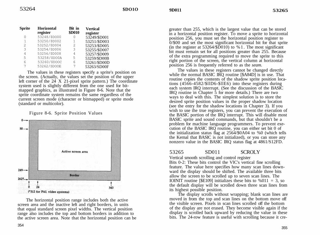
53264
Sprite Horizontal Bit inregister $D010
0 53248/$DO00 01 53250/$D002 12 53252/$D004 23 53254/$D006 34 53256/$D008 45 53258/$DO0A 56 53260/$DOOC 67 53262/SDOOE 7
$DO1O
Verticalregister53249/$D00153251/$D00353253/$D00553255/$D00753257/$D00953259/$D00B53261/$D00D53263/SD00F
The values in these registers specify a sprite's position onthe screen. (Actually, the values set the position of the upperleft corner of the 24 X 21-pixel sprite pattern.) The coordinatesystem used is slightly different from the one used for bit-mapped graphics, as illustrated in Figure 8-6. Note that thesprite coordinate system remains the same regardless of thecurrent screen mode (character or bitmapped) or sprite mode(standard or multicolor).
Figure 8-6. Sprite Position Values
The horizontal position range includes both the activescreen area and the inactive left and right borders, in unitsthat equal standard screen pixel widths. The vertical positionrange also includes the top and bottom borders in addition tothe active screen area. Note that the horizontal position can be
354
9D011 53265
greater than 255, which is the largest value that can be storedin a horizontal position register. To move a sprite to horizontalposition 256, you must set the horizontal position register to0/$00 and set the most significant horizontal bit for that sprite(in the register at 53264/$D010) to % 1 . The most significantbit must remain set for all positions greater than 255. Becauseof the extra programming required to move the sprite to thisright portion of the screen, the vertical column at horizontalposition 256 is frequently referred to as the seam.
The values in these registers cannot be changed directlywhile the normal BASIC IRQ routine [$A84D] is in use. Thatroutine copies the contents of the shadow sprite position loca-tions (4566-4582/$llD6-$llE6) into these registers duringeach system IRQ interrupt. (See the discussion of the BASICIRQ routine in Chapter 5 for more details.) There are twoways to deal with this. The simplest solution is to store thedesired sprite position values in the proper shadow location(see the entry for the shadow locations in Chapter 3). If youwish to use the true registers, you can prevent the execution ofthe BASIC portion of the IRQ interrupt. This will disable mostBASIC sprite and sound commands, but that shouldn't be aproblem for machine language programmers. To prevent exe-cution of the BASIC IRQ routine, you can either set bit 0 ofthe initialization status flag at 2564/$0A04 to %0 (which tellsthe Kernal that BASIC is not initialized), or you can store anynonzero value in the BASIC IRQ status flag at 4861/S12FD.
53265 SD011 SCROLYVertical smooth scrolling and control registerBits 0-2: These bits control the VlC's vertical fine scrollingfeature. The value here specifies how many scan lines down-ward the display should be shifted. The available three bitsallow the screen to be scrolled up to seven scan lines. TheIOINIT routine [$E109] initializes these bits to %011 = 3, sothe default display will be scrolled down three scan lines fromits highest possible position.
The display scrolls without wrapping; blank scan lines aremoved in from the top and scan lines on the bottom move offthe visible screen. Pixels in scan lines scrolled off the bottomof the display are not erased. They become visible again if thedisplay is scrolled back upward by reducing the value in thesebits. The 24-row feature is useful with scrolling because it cre-
355

53265 $D011 I $D012 53266
ates hidden scan lines at the top and bottom of the screen thatcan be scrolled onto the visible area.Bit 3: This bit determines the vertical height of the active por-tion of the screen display. Setting this bit to %1 selects a 25-row (200 scan-line) active screen. The bit is initialized to thissetting during the IOINIT routine [$E109], and neither the op-erating system nor BASIC changes this value. Setting this bitto %0 reduces the height of the active portion of the displayto 24 rows (192 scan lines) by blanking the top four and bot-tom four scan lines of the display. The pixels in the blankedcolumns aren't erased; they'll still be intact when the screen isswitched back to 25 rows. The 24-row feature is useful in con-junction with the vertical scrolling feature described in bits 0-2.
Bit 4: This bit enables or disables the VIC screen display.While the bit is % 1 , the VIC provides its normal screen out-put. The bit is initialized to this setting during the IOINIT rou-tine [$E109]. When the bit is set to %0, the VIC suspends theactive portion of the display and provides a solid screen in theborder color specified in the register at 53280/$D020. Thescreen is not erased, just blanked. Any text or graphics willstill be intact if the screen is again enabled. With the displayblanked, the VIC doesn't have to steal timing cycles from theprocessor as it normally does. As a result, the 128 actuallyruns about 7 percent faster with the VIC display off.
There are several uses for this blanking feature. For ex-ample, you could blank the display while drawing a complexbitmapped graphics screen, then dramatically unveil the com-pleted picture by reenabling the display. Since the VIC cannotprovide a proper display at the 2-MHz clock rate, the VIC dis-play is normally blanked when the system is switched to fastmode. One step in the BASIC statement FAST involves settingthis bit to %0. The SLOW statement returns it to % 1 . This bitis also set to %0 to blank the screen during tape operations,and restored to %1 upon completion of the operations.Bit 5: This bit selects whether the VDC will generate a charac-ter mode display or a bitmapped mode display. (See the intro-duction to this section for a discussion of the display modes.)Setting this bit to %0 selects character mode, while setting itto %1 selects bitmapped mode.
This bit cannot be directly modified while the normal sys-tem interrupt sequence is active because a step in the screen
356
editor IRQ routine [$C194] sets this bit according to the screenmode flag (location 216/$D8). To change the setting of thisbit, you can either store the appropriate value in the flag loca-tion, or you can disable the screen-setup portion of the IRQroutine and change this bit directly. To use the flag location,set bit 5 of location 216/$D8 to the desired setting (%0 or %1)for the register bit. To turn off the screen-setup portion of theinterrupt routine, store the value 255/SFF in location 216/$D8.
Bit 6: This bit controls extended background color mode,which offers a choice of four different background colors foreach character position. For details about this mode, refer tothe introduction for this section. Extended background colormode is enabled when this bit is set to % 1 . The mode worksonly in conjunction with character mode. You should not se-lect extended background color mode while bit 5 is set to %1to select bitmapped mode.Bit 7: This bit is effectively the ninth bit of the raster registerat 53266/$D011. Refer to the discussion of that register fordetails. The extra bit is necessary because a full screen con-tains more than 256 scan lines.
53266 $D012 RASTERRaster compare registerThis register has two different functions, depending onwhether it is being read from or written to. As explained inthe introduction for this section, the video screen display con-sists of a stack of thin horizontal lines of dots called a raster.When the register is read, the value returned is the number ofthe raster scan line currently being drawn. The range of scan-line numbers depends on the video system in use. For NTSC(North American) systems, values can be in the range 0-262,while PAL (European) systems have a maximum count of over300. In either case, the active portion of the screen consists ofscan lines 50-249.
The maximum scan-line number in either system is largerthan can be held in a single eight-bit register, so bit 7 of theregister at 53265/$D011 is used to hold the ninth bit of thevalue. When bit 7 of 53265/$D011 is % 1 , you should add256/ $100 to the value in this register to get the true scan-linenumber. For scan line 262, for example, bit 7 of 53265/$D011will be %1 and the value in this register will be 6/$06. Be-
357

53267 $D013
cause the value in this register changes so rapidly (over 15,000times per second), it can't be read usefully from BASIC. By thetime you PEEKed the value into a variable, the raster scan linewould have moved far beyond the line recorded in the vari-able value.
When you write to this register or to bit 7 of 53265/$D011, the value written is stored in an internal nine-bit rastercompare latch register. Whenever the current scan-line countequals the value in this register, bit 0 of the interrupt registerat 53273/$D019 will be set to % 1 . If bit 0 of the interruptmask register at 53274/$D01A was previously set to %1 , thiswill also trigger an external interrupt request to the processor.The value you store in this register represents the scan line atwhich you wish the interrupt to occur. For scan-line valuesless than 256, you must also set bit 7 of 53265/$D011 to %0.For scan-line values of 256 or greater, you must set bit 7 of53265/$D011 to %1 and store the line number minus 256 inthis register. To calculate the top scan line corresponding toany row of character positions, use the following formula:scan line = (row * 8) + 50where the row value is in the range 0-24.
Raster interrupts can be used to program a variety of spe-cial video effects, including split screens like those in theGRAPHIC 2 and GRAPHIC 4 modes. The 128 also uses a ras-ter interrupt off the visible screen (at scan line 255) to drivethe system IRQ sequence. Because of this, you cannot write anew value directly to this register while the the normal systeminterrupt sequence is in use. The screen-setup portion of thescreen editor IRQ routine [$C194] will write the value 255/$FFto this register on every pass, except when setting up the bit-mapped portion of a split bitmapped/text screen. In that case,the value in location 2612/$0A34 will be copied into the reg-ister. In either case, bit 7 of the register at 53265/$D011 willbe set to %0. To use a raster interrupt for your own purposes,you must write a new interrupt routine. Refer to Appendix Afor more information.
53267 $D013 LPENX53268 SD014 LPENYLight pen horizontal and vertical positionsWhenever the VIC's LP input line is brought to a low (0 volts)state, the raster beam's horizontal dot position and vertical
358
$D014 53268
scan line are latched into these registers. The register at53267/SD013 will hold the horizontal position value, and theone at 53268/$D014 will hold the vertical position value. Tosignal that a new value has been latched, bits 7 and 3 of theinterrupt register at 53273/SD019 will be set to % 1 . Theseregisters are read-only; writing to them has no effect. The reg-isters are not cleared when read; the latched values will be re-tained until the LP line is again brought low.
The range of scan-line values in the register at 53268/$D014 is the same as the range of sprite vertical positionsshown in Figure 8-6. For example, the top scan line of the ac-tive screen area is 50, In that figure, you'll note that the rangeof horizontal positions extends to 343, which is greater thancan be represented in a single eight-bit register. To compen-sate, the range of horizontal values in the register at 53267/$D013 is the equivalent of one-half the range of horizontalvalues shown in Figure 8-6. For example, the horizontal-positionvalue for the center of the screen is 184, so the correspondinglight pen position will be about 92.
The LP line is connected to pin 6 of control port 1 (con-trol port 2 does not support a light pen). A light pen has at itstip an electronic device known as a phototransistor, which isconnected so as to cause a low pulse whenever the videobeam moves past the pen. These registers can be tricked intoreading false values. Pin 6 of control port 1 is also used forlight pen input for the VDC chip, so a light pen signal gener-ated on the 80-column screen will latch meaningless values inthese registers. In lieu of a light pen, several other events cancause a pulse on the LP line. That control port pin is also usedfor the joystick fire button, so pressing the button of a joystickplugged into port 1 will also latch values in these registers. Be-cause of this joystick button function, the port line is also con-nected to the line from row 4 of the keyboard matrix. This hastwo consequences. First, pressing any of the following keyswith no light pen connected will latch meaningless values: Fl,Z, C, B, M, period, right SHIFT, space, the 2 and ENTER keyson the numeric keypad, and the ^ key in the cursor group.More significantly, while a light pen is connected, all of thesekeys will be "dead," and cannot be typed.
359

53269 $D015
53269 $D015 SPENASprite enable register
This register controls which sprites are enabled. Only enabledsprites can be visible, and only enabled sprites can be in-volved in collisions. Setting a bit in this register to %1 enablesthe corresponding sprite. However, an enabled sprite won't bevisible unless it is also positioned within the visible screenarea, has a pattern definition that includes some nonzero bits,and is set to a color different from the screen backgroundcolor. Setting a bit in this register to %0 turns off the cor-responding sprite, but does not change the setting of any otherparameters. When reenabled, the sprite will still have thesame position, color, and pattern (unless those were changedwhile the sprite was turned off). The sprites are controlled asfollows:
Bit Bit value Sprite controlled0 l/$01 ' 01 2/$02 12 4/$04 23 8/$08 34 16/S10 45 32/$20 56 64/$40 67 128/$80 7
This register is initialized to 0/$00 (all sprites disabled) bythe IOINIT routine [$E109], part of the reset and RUN/STOP-RESTORE sequences. Sprites are normally disabledduring tape and serial bus operations to prevent timing prob-lems. In this case, the contents of the register are stored in lo-cation 2616/$0A38 for the duration of the operation, thenrestored to the register when the operation is completed. Youcan prevent this and keep sprites enabled by setting bit 7 ofthe custom mode flag (2618/$0A3A) to % 1 .
53270 $D016 SCROLXHorizontal smooth scrolling and control register
Bits 0-2: These bits control the VIC's horizontal smooth scroll-ing feature. The value here specifies the number of pixels thedisplay is to be shifted to the right. The available three bitsallow the screen to be shifted as many as seven pixels. Thedisplay scrolls without wrapping; blank pixels are moved infrom the left and pixels on the right move off the visible
$D016 53270
screen. Pixels scrolled off the right are not erased, just hidden.They will become visible again if the display is scrolled backto the left by reducing the value in these bits. The 38-columnfeature is useful with scrolling because it creates a hidden leftcolumn that can hold pixels to be scrolled onto the visible area.
Bit 3: This bit determines the horizontal width of the screen.Setting this bit to %1 selects a 40-column (320-pixel) screen.The bit is initialized to this setting during the IOINIT routine[$E109], and neither the operating system nor BASIC everchange this value. Changing this bit to %0 reduces the widthof the active portion of the display to 38 columns (304 pixels)by blanking the leftmost and rightmost columns. (Actually, 7pixels on the left and 9 on the right are blanked.) The contentsof the blanked columns aren't erased; they'll still be intactwhen the screen is switched back to 40 columns. The 38-columnfeature is useful in conjunction with the horizontal scrollingfeature in bits 0-2. Scrolling the 38-column screen the maxi-mum 7 pixels to the right will make the contents of the previ-ously hidden leftmost column visible.
Bit 4: This bit controls multicolor mode for both the characterand bitmapped screens. While this bit is %0, foreground pixelswill be limited to one color (although the color can be differ-ent for every character position). Setting this bit to %1 enablesmulticolor mode, which allows a choice of three different col-ors for each foreground pixel. However, selecting multicolormode also cuts horizontal resolution for the screen in half. Se-lecting multicolor mode for the screen has no effect on anysprites that might be displayed on that screen. Sprite multi-color mode is controlled by the register at 53276/$D01C.
This bit cannot be directly modified while the normal sys-tem interrupt sequence is active because a step in the screeneditor IRQ routine [$C194] sets this bit according to the screenmode flag (location 216/$D8). To change the setting of this bitfor bitmapped mode, you can either store the appropriatevalue in the flag location, or you can disable the screen-setupportion of the IRQ routine and change this bit directly. To usethe flag location, set bit 7 of location 216/$D8 to the desiredsetting (%0 or %1) for the register bit. To turn off the screen-setup portion of the interrupt routine, store the value 255/$FFin location 216/SD8. To select multicolor character mode, youmust use the option to disable the screen setup, since the textmode-setup subroutine always sets this bit to %0.
361

53271 $D017
Bit 5: This bit is referred to in Commodore literature as the re-set bit, but its intended usage is unclear. The value here hasno apparent affect on any VIC operations.
Bits 6-7: These bits are unused. Writing to them has no effect,and they always return %1 when read.
53271 $D017 YXPANDSprite vertical expansion registerEach bit in this register controls the vertical expansion featurefor one of the eight sprites. The relationship of sprites to regis-ter bits is the same as for the sprite enable register (53269/$D015). Setting a bit here to %1 will double the verticalheight of the corresponding sprite. Each sprite can be ex-panded independently, with regard for the background screenon which the sprite is displayed. The resolution of the sprite isnot increased—it will still be 21 pixels tall—but the height ofthe pixels will be doubled. Vertical expansion can be selectedin conjunction with horizontal expansion to double the size ofa sprite. (Horizontal expansion is controlled by the register at53277/SD01D.) The default value in this register, establishedby the IOINIT routine [$E109], is 0/$00, so no sprites are ini-tially expanded.
53272 $D018 VMCSBScreen and character base address registerThe value in this register determines the location within thecurrent 16K VIC video bank of the two movable componentsof video memory: the screen memory/video matrix and char-acter memory/bitmap areas. (There is no provision for movingcolor memory; that area always appears at 55296-56319/$D800-$DBFF.) The contents of this register cannot be changeddirectly while the normal system IRQ interrupt sequence is inuse. The screen editor IRQ routine [$C194] copies the contentsof a shadow location into this register during each interrupt.The shadow location depends on the screen mode in use. Fortext mode, or for the text portion of a split screen, the contentsof location 2604/$0A2C will be copied here. For bitmappedmodes, the value in location 2605/S0A2D will be copied intothe register. You have two choices for changing the value inthis register. You can either store the desired value in the ap-propriate shadow location, or you can turn off the screen-
362
S D 0 1 8 53272
setup portion of the screen editor IRQ routine to gain directaccess to the register. To disable the screen-setup step, storethe value 255/$FF in location 216/$D8.
Bit 0: This bit is unused. Writing to it has no effect, and italways returns %1 when read. Thus, the value read from thisregister will always be odd.
Bits 1-3: The value in these bits determines the location of char-acter memory (for character mode) or of the bitmap (for bit-mapped modes). For character mode, a complete 256-characterset requires 2048 (2K) bytes, and the character set must starton an even 2K memory address boundary. Possible selectionsare as follows:
Bits Offset for3 2 1 character set0 0 0 0/$000 0 1 2048/$08000 1 0 4096/$10000 1 1 6144/$18001 0 0 8192/$20001 0 1 10240/$28001 1 0 12288/$30001 1 1 14336/S3800
These bits do not determine the absolute address of the char-acter set, but rather the offset from the starting address of thecurrent video bank. For example, video bank 2 begins at ad-dress 32768/$8000, so a bit setting of %100 in that casewould place the character set at 32768 + 8192 = 40960/$A000.However, the default video bank (bank 0) begins at location0/$0000, so in that case the offset is equal to the actual address.
The 128 normally provides a pair of character sets and al-lows you to switch between them by pressing the SHIFT -Commodore key combination. If you are setting up a singlecustom character set, you should disable this characterset-switching feature by setting bit 7 of location 247/$F7 to% 1. If you wish to retain the character set-switching feature,you must provide two character sets, one at an "even" posi-tion (one for which bit 1 of this register is %0), and the otherat the next higher ("odd") position.
The CINT screen editor initialization routine [$C07B] setsbits 1-3 to %010 in location 2604/$0A2C, the shadow for thisregister in text mode. This places the default character memoryat an offset of 4096/$1000 from the starting address of the
363

53272 $D018
video bank (and implies that the alternate character set will belocated at an offset of 6144/$1800), This may seem strange,since there is certainly no character pattern data stored inRAM at addresses 4096-8191/$1000-$lFFF/ and since the128's memory map shows that the character ROM is actuallylocated at addresses 53248-57343/$D000-$DFFF. However,the 128 has the capability to make the VIC chip see characterROM at addresses 4096-6143/$1000-$17FF (for the uppercase/graphics set) and addresses 6144-8191/$1800-$lFFF (for thelowercase/uppercase set) in any video bank. (Note that this isa change from the Commodore 64, which could only see char-acter ROM in video banks 0 and 2.) Only the VIC will see thecharacter ROM at those addresses. To the processor, those lo-cations will still be RAM.
This feature is controlled by bit 2 of the 8502's built-inI/O port, at location l/$01. When bit 2 of the register atl/$01 is %0, the VIC chip will see character ROM in the char-acter memory areas beginning at addresses 4096/$1000 and6144/$1800. No other character memory slots are affected.When the I/O port bit is set to % 1 , the VIC will instead seethe true contents of RAM at those addresses rather than im-ages of the character ROM. Like other screen control locations,the I/O port bit has a shadow location. Bit 2 of location217/SD9 is copied into bit 2 of location l/$01 during eachpass through the text screen-setup portion of the screen editorIRQ routine. To switch out character ROM, you must set bit 2of the shadow location to %1 (store the value 4/$04 in loca-tion 217/$D9). Alternatively, you can disable the screen-setupportion of the screen editor IRQ routine by storing the value255/$FF in location 216/$D8; then you change bit 2 of loca-tion l/$01 directly.
Finding free space for a custom character set can be a chal-lenge. If you are using machine language exclusively, any ofthe character set slots above address 4864/$1300 can be used,but none of the address slots are completely free in the stan-dard configuration with BASIC. If you disable character ROM,there is free memory at 6144-7167/$ 18OO-$1BFF for half a char-acter set (128 character patterns). If your program doesn't usea bitmapped screen, you can allocate a bitmap area and thenuse the reserved space for custom character sets. For example,if your BASIC program includes the statements GRAPHIC1:GRAPHIC 0, the area from 7168-16383/ $1COO-$3FFF will
364
SD018 53272
be protected from BASIC, and any character memory slot inthat area can be used to hold the new character set.
Since the bitmap for a high-resolution display requires8000 bytes of memory and must begin at an even 8K memoryaddress boundary, there are only two possible positions forthe bitmap within the 16K video bank. When you are specify-ing the location of the bitmap, only the setting of bit 3 is sig-nificant. When that bit is %0, the bitmap will begin at anoffset of 0/$0000 from the start of the video bank. When bit 3is %1 , the bitmap begins at an offset of 8192/$2000 from thestart of the video bank. The CINT screen editor initializationroutine [$C07B] sets bits 1-3 to %100 in location 2605/$0A2D,the shadow for this register in bitmapped mode, so the defaultlocation of the bitmap is 8192/$2000 bytes beyond the start ofthe video bank (address 8192/$2000 for the default video bank).
Bits 4-7: These bits determine the location of the video matrixarea, which is used as screen memory in character mode andto hold color information in bitmapped mode. The video ma-trix requires 1000 bytes of memory and must start on an evenIK address boundary. Possible selections are as follows:
Bits Offset for7 6 5 4 video matrix0 0 0 0 0/$00000 0 0 1 1024/$04000 0 10 2048/$08000 0 11 3072/$OC000 10 0 4096/$10000 10 1 5120/$14000 1 1 0 6144/$18000 1 1 1 7168/$1COO10 0 0 8192/$2000
0 0 1 9216/$24000 1 0 10240/$28000 1 1 11264/$2C001 0 0 12288/$30001 0 1 13312/$34001 1 0 14336/S38001 1 1 15360/$3CO0
These bits do not determine the absolute address of the videomatrix, but rather the offset from the starting address of thecurrent video bank. For example, video bank 3 begins at ad-dress 49152/$C000, so a bit setting of %0010 in that casewould place the character set at 49152 + 2048 = 51200/
365

53273 $D019
$C800. However, the default video bank (bank 0) begins at lo-cation 0/$0000, so in that case the offset is equal to the actualaddress.
The C1NT screen editor initialization routine [$C07B] setsbits 4-7 to %0001 in location 2604/$0A2C, the shadow forthis register in text mode. This places the default charactermemory at an offset of 1024/$0400 from the starting addressof the video bank. You can't change this register directly whilethe normal system interrupt sequence is active. To move thevideo matrix for the text screen, you can either change thevalue in location 2604/$0A2C, or you can turn off the screen-setup portion of the interrupt sequence by storing the value255/$FF in location 216/$D8. After that, you can change theregister directly. Even if you change the value in this register,all printed characters will continue to go to the former screenmemory range until you change the value in location 2619/$0A3B to reflect the new starting page for screen memory.
Because the bitmap for a high-resolution display requireshalf of the memory available in a 16K video bank, only half ofthe possible addresses are really useful. When setting up a bit-mapped display, you should select a video matrix area in theportion of the video bank not occupied by the bitmap. TheCINT screen editor initialization routine [$C07B] sets bits 4-7to %0111 in location 2605/$0A2D, the shadow for this regis-ter in bitmapped mode, so the default location of the videomatrix in that mode is 7168/$1COO bytes from the start of thevideo bank (address 7168/$1COO for the default video bank).Thus, the bitmapped mode video matrix will not disturb char-acter mode screen memory.
To move the video matrix for the bitmapped screen, youcan either change the value in location 2605/$0A2D, or youcan turn off the screen-setup portion of the interrupt sequenceby storing the value 255/$FF in location 216/SD8. After that,you can change the register directly.
$D019 VICIRQ53273Interrupt registerThis register is read-only; writing to this location has no effect.Bits 0-3 indicate the status of the four interrupt sources for theVIC chip. These bits will always reflect the status of their cor-responding events, regardless of whether or not register53274/$D01A has been set to trigger an external interrupt re-
366
$D01A 53274
quest for the event. Once a bit here is set to %1 , it will retainthat value until the register is read, at which time all func-tional bits are reset to %0.Bit 0: This bit will be set to %1 whenever the raster scan-linecount equals the value in the raster compare register 53266/$D012 (plus bit 7 of 53265/$D011).Bit 1: This bit will be set to %1 whenever a nontransparentportion of a sprite overlaps any screen foreground pixels. (Re-member, however, that for multicolor character or multicolorbitmapped screens, no collision can be detected betweensprites and foreground pixels represented by %01 bit patterns.)The register at 53279/$D01F records which sprites are in-volved in collisions with foreground data.
Bit 2: This bit will be set to %1 whenever two or more spritesoverlap. Collisions can only be detected between the fore-ground portion of the sprites, those pixels represented by non-zero bit patterns. No collision is detected when the over-lapping portions of the sprites are transparent (when the pixelsare represented by %0 or %00 bit patterns). The register at lo-cation 53278/$D01E records which sprites are involved in col-lisions with other sprites.
Bit 3: This bit will be set to %1 whenever a new value islatched into the light pen registers at 53267-53268/$D013-$D014.Bits 4-6: The bits are not used, and always return %1 whenread.Bit 7: Whenever any internal interrupt source sets one of theother bits in this register to % 1 , this bit will also be set to %1to indicate that an internal interrupt has been recorded. Thus,you need to test only this bit to determine whether an internalinterrupt has occurred. Note that this register is automaticallycleared after it is read, so you'll need to save the register valuebefore testing this bit if you want to be able to subsequentlyread any of the other bits.
53274 $D01A IRQMSKInterrupt enable registerCertain events such as sprite-sprite collisions always generateinternal VIC interrupts, recorded in the register at 53273/
367
53275 SD01B
$D019. The VIC chip has the capability to generate an exter-nal interrupt request to the processor as a result of any ofthese conditions. In the 128, the VIC's interrupt request outputline is connected to the processor's IRQ line, so internal VICevents can trigger processor IRQ interrupts. See Appendix Afor more information on IRQ interrupts.
Bit 0: Setting this bit to %1 enables an external interrupt re-quest when the raster count match is recorded in the flag atbit 0 of the register at 53273/$D019. Because raster interruptsare the normal source of the system jiffy interrupt that driveskeyboard scanning and other important housekeeping fea-tures, this bit is initialized to %1 by the Kernal IOINIT routine[$E109]. Changing this bit to %0 will completely disable thesystem interrupt.
Bit 1: Setting this bit to %1 enables an external interrupt re-quest when a sprite-foreground collision is recorded in the flagat bit 1 of the register at 53273/$D019, as when a spritepasses over a character on the text screen.
Bit 2: Setting this bit to %1 enables an external interrupt re-quest when a sprite-sprite collision is recorded in the flag atbit 2 of the register at 53273/$D019.
Bit 3: Setting this bit to %1 enables an external interrupt re-quest when a new value is recorded in the flag at bit 3 of theregister at 53273/$D019. It is risky to use this interruptsource, because a number of events other than the light pencan trigger the latching of values into these registers. See theentry for the light pen registers for details.
Bits 4-7: These bits are unused; writing to them has no effect,and they always return %1 when read. Thus, the value seenwhen this register is read will always be at least 240/$F0. Tomask off these unused bits and see the valid interrupt settings,use AND 15 in BASIC or AND #$0F in machine language.
53275 8D01B SPBGPRSprite-to-foreground priority registerEach bit in this register controls the sprite-to-foreground prior-ity for one of the eight sprites. The relationship of sprites tobits is the same as for the sprite enable register (53269/$D015). While a bit here is %0, the corresponding sprite willhave higher priority than the screen foreground, and will thusappear to pass in front of anything displayed in the fore-
368
$D01D 53277
ground color on the text or bitmapped screens. When a bithere is set to % 1 , the corresponding sprite will have lower pri-ority than the screen foreground, and will thus appear to passbehind anything displayed in the foreground color. For multi-color character or multicolor bitmapped screen modes, thelow-priority sprite will appear to pass behind screen pixelsrepresented by %10 and %11 bit patterns, but will still pass infront of pixels represented by %01 bit patterns. (The sprite al-ways appears in front of pixels with the %00 background bitpattern.) The default value for this register, established by theIOINIT routine [$E109], is 0/$00, so all sprites initially havehigher priority than the screen foreground.
5 3 2 7 6 8D01C SPMCSprite multicolor mode registerEach bit in this register controls the multicolor feature for oneof the eight sprites. The relationship of sprites to register bitsis the same as for the sprite enable register (53269/$D015).Setting a bit here to %1 selects multicolor mode for the cor-responding sprite. Multicolor mode can be selected indepen-dently for each sprite, and standard and multicolor sprites canbe mixed freely on the same screen. Multicolor sprites are notrestricted to multicolor screen modes; they can be used freelyin standard screen modes as well. The default value for thisregister, established during the IOINIT routine [$E109], is0/$00, so no sprites are initially in multicolor mode.
Selecting multicolor mode for a sprite reduces the numberof horizontal pixels for the sprite from 24 to 12. However, thesprite remains the same size; the multicolor sprite pixels aretwice as wide. Two bits of the pattern definition are requiredfor each pixel. All pixels represented by %00 are transparent;whatever is behind the sprite will show through. Pixels with%01 and %11 bit patterns take their color values from the reg-isters at 53285/$D025 and 53286/$D026, respectively, whichare common to all multicolor sprites. Pixels with %10 bit pat-terns take the color specified in the color register for the par-ticular sprite (53287-53294/$D027-$D02E).
53277 $D01D XXPANDSprite horizontal expansion registerEach bit in this register controls the horizontal expansion fea-ture for one of the eight sprites. The relationship of sprites to
369

53278 $D01E
register bits is the same as for the sprite enable register(53269/$D015). Setting a bit here to %1 will double the hori-zontal width of the corresponding sprite. Each sprite can beexpanded independently, without regard for the backgroundscreen on which the sprite is displayed. The resolution of thesprite is not increased (it will still be 24 pixels wide) but thewidth of the pixels will be doubled. Horizontal expansion canbe selected in conjunction with vertical expansion to doublethe size of a sprite. (Vertical expansion is controlled by theregister at 53271/$D017.) The default value in this register,established by the IOINIT routine [$E109], is 0/$00, so nosprites are initially expanded.
53278 8D01E SPSPCLSprite-to-sprite collision registerThis register records collisions between two or more sprites.This register is read-only; storing values here has no effect. Acollision occurs whenever any nontransparent portions of thesprites overlap. Transparent pixels (pixels with bit patterns of%0 or %00) are not involved in collisions. When sprites col-lide, the bits in this register corresponding to those sprites areset to %1 (the correspondence between sprites and bits is thesame as for the sprite enable register). Since a minimum oftwo sprites are involved in any sprite-sprite collision, at leasttwo bits will be set. The register is automatically cleared to0/$00 after each time it is read, so you'll need to store thevalue you read if you wish to perform multiple tests. Bit 2 ofthe interrupt register at 53273/$D019 will also be set to %1whenever any sprite-sprite collision occurs.
This register indicates only that sprites have collided. Itdoes not necessarily tell you which sprites are involved in aparticular collision. If only two bits are set, then those spritesobviously must have hit each other. However, if you find thatthree or more bits are set, you must read the horizontal andvertical position registers for the involved sprites and deter-mine which sprites are in contact with each other. Rememberthat the sprite position registers return the position of the up-per left corner of the sprite, which may not be the point of thesprite that is colliding with the foreground.
One thing to beware of when reading this register is thatafter a sprite overlaps a foreground object, the register willcontinue to record collisions until the sprite is moved away
370
$D020 53280
from the object. Also, sprite-sprite collisions can occur evenwhen the sprites are located completely outside the visiblescreen area.
53279 $D01F SPFGCLSprite-foreground collision registerThis register records collisions between sprites and the screenforeground. This register is read-only; storing values here hasno effect. A collision occurs whenever any pixel in a spriterepresented by a nonzero bit pattern overlaps any foregroundpixel on the screen, as when a sprite passes over a characteron the text screen. Background or transparent pixels are notinvolved in collisions. For the purposes of collision detection,multicolor screen pixels represented by %01 bit patterns arenot considered foreground, and no collision will be detectedwhen a sprite pixel overlaps a multicolor screen %01 pixel.When a sprite collides with a foreground pixel, the bit in thisregister corresponding to that sprite is set to %1 (the cor-respondence between sprites and bits is the same as for thesprite enable register). The register is automatically cleared to0/$00 after each time it is read, so you'll need to store thevalue you read if you wish to perform multiple tests. Bit 1 ofthe interrupt register at 53273/$D019 will also be set to %1whenever any sprite-foreground collision occurs.
This register indicates only that a sprite has collided withsome portion of the screen foreground. It does not tell you ex-actly what the sprite is overlapping. To determine that, youmust determine which sprite or sprites are involved in colli-sions, then read the horizontal and vertical position registersfor the involved sprites and determine what screen-foregroundobject is located in that vicinity. Remember that the sprite po-sition registers return the position of the upper left corner ofthe sprite, which may not be the point of the sprite that is col-liding with the foreground.
One thing to beware of when reading this register is thatafter a sprite overlaps a foreground object, the register willcontinue to record collisions until the sprite is moved awayfrom the object.
53280 $D020 EXTCOLBorder color registerThe value in this register determines the color of the screenborder, the area of the screen surrounding the active portion
371

53281 SD021
of the display. When the screen is blanked by setting bit 4 ofthe register at 53265/$D011 to %0, the entire display area willbe filled with the color specified here. Since the VIC can pro-duce only 16 different colors, only four bits are required tohold all possible color values. Thus, only bits 0-3 of this loca-tion hold meaningful values. Bits 4-7 are unused; writing tothose bits has no effect, and the bits always return % 1 whenread. Thus, the value in this register will always be at least240/$F0. To mask off these bits and read the true color valueyou should use AND 15 in BASIC or AND #$0F in machinelanguage. See Table 8-1 for a list of standard VIC color values.The default setting for this register, established by the IOINITroutine [$E1O9], is 13/$0D (light green). From BASIC, thevalue here can be changed using the statement COLOR 4,rc(where n is the desired BASIC color number; BASIC colornumbers are equal to VIC color values plus one).
53281 $DO21 BGCOLOBackground color register 0In standard character mode, the value here determines thecolor of all pixels in a screen position which are representedby %0 bits in the character pattern. This background color iscommon to all screen positions. Clearing the screen fills all po-sitions with the screen code for the space character, which hasa pattern that is all %0 bits. Thus, a cleared screen will be filledwith the color specified here. The color of pixels with %1 bits inthe character pattern (the foreground color) is determined bythe value in the color memory location for the position.
This register is also used in both of the other charactermodes. In multicolor character mode, the value here deter-mines the color of all pixels in all screen positions representedby %00 bit pairs in the character pattern. In extended back-ground color mode, the value here determines the backgroundcolor in any screen positions for which bits 6-7 of the screencode in the corresponding screen memory location are %00.This register is unused in standard bitmapped mode, but formulticolor bitmapped mode the value here determines thecolor for all pixels represented in the bitmap by %00 bit pairs.
Since the VIC can produce only 16 different colors, onlyfour bits are required to hold all possible color values. Thus,only bits 0-3 of this location hold meaningful values. Bits 4-7are unused; writing to those bits has no effect, and the bits al-
372
$D024 53284
ways return %1 when read. Thus, the value in this registerwill always be at least 240/$F0. To mask off these bits andread the true color value you should use AND 15 in BASIC orAND #$0F in machine language. See Table 8-1 for a list ofstandard VIC color values. This register is initialized toll /$0B (dark gray) by the IOINIT routine [$E109], part ofboth the reset and RUN/STOP-RESTORE sequences. FromBASIC, the value here can be changed using the statementCOLOR 0,n (where n is the desired BASIC color number;BASIC color numbers are equal to VIC color values plus one.)
53282 $D022 BGCOL153283 $D023 BGCOL253284 $D024 BGCOL3Background color registers 1-3These three registers are used only when multicolor charactermode or extended background color mode is enabled. Formulticolor character mode, the value in 53282/SD022 deter-mines the color of any pixels in a screen position representedby %01 bit pairs in the character pattern, and the value in53283/SD023 determines the color of all pixels with %10pairs. Since there is only one set of registers for all screen po-sitions, the colors of pixels with %01 and %10 bit pairs will becommon to all characters on the screen. The color of pixelswith %00 bit pairs is determined by the value in53281/SD021, and the color of pixels with %11 bit pairs is se-lected individually for each character position by the value inthe corresponding color memory location (55296-56319/$D800-$DBFF). The register at 53284/$D024 is unused in mul-ticolor character mode,
For extended background color mode, these registers de-termine the background color for the character position for thecharacter, depending on the setting of bits 6-7 of the screencode in the screen memory location for the position. The se-lections are as follows:Bits7 60 00 11 01 1
Background color source register
53281/SD02153282/$D02253283/$D02353284/$D024
373

53235 $D025
Since the VIC can produce only 16 different colors, onlyfour bits are required to hold all possible color values. Thus,only bits 0-3 of these locations hold meaningful values. Bits4-7 in any of these locations are unused. Writing to those bitshas no effect, and the bits always return % 1 when read. Thus,the value in any of these locations will always be at least240/$F0. To mask off these bits and read the true color valueyou should use AND 15 in BASIC or AND #$0F in machinelanguage. See Table 8-1 for a list of standard VIC color values.These registers are initialized during the IOINIT routine[$E019], part of the reset and RUN/STOP-RE STORE se-quences. The default values are 1 (white) for 53282/$D022, 2(red) for 53283/$D023, and 3 (cyan) for 53284/$D024. Thereis no BASIC statement specifically for changing the settings ofthese registers.
53285 $D025 SPMCO53286 $D026 SPMC1Sprite multicolor registersThe values in these registers determine two of the colors formulticolor sprites. (A sprite can be switched to multicolormode by setting the appropriate bit in the register at 53276/$D01C.) The value in the register at 53285/$D025 determinesthe color for all pixels in the sprite represented by %01 bitpairs in the pattern. The value in 53286/$D026 determines thecolor for all pixels represented by %11 bit pairs. Since thereare only these two registers for all eight sprites, the colors ofpixels with %01 and %11 bit pairs will be common to allsprites. The color of pixels represented by %10 bit pairs can beselected individually for each sprite using the registers at53287-53294/$D027-$D02E. Pixels with %00 bit pairs in thepattern will be transparent.
Since the VIC can produce only 16 different colors, onlyfour bits are required to hold all possible color values. Thus,only bits 0-3 of these locations hold meaningful values. Bits4-7 in any of these locations are unused. Writing to those bitshas no effect, and the bits always return %1 when read. Thus,the value in any of these locations will always be at least240/$F0. To mask off these bits and read the true color valueyou should use AND 15 in BASIC or AND #$0F in machinelanguage. See Table 8-1 for a list of standard VIC color values.The default settings of these registers, established by the
374
SD02E 53294
IOINIT routine [$E109], are 1 (white) for 53285/$D025 and 2(red) for 53286/$D026. From BASIC, these settings can bechanged using the SPRCOLOR statement.
5328753288532895329053291532925329353294
SD027SD028SD029$D02A8D02B$D02C$D02D$D02E
SPOCOLSP1COLSP2COLSP3COLSP4COLSP5COLSP6COLSP7COL
Sprite color registersEach of these registers holds color information for one of theeight sprites. For standard sprites, the value here determinesthe color of all %1 bits in the sprite pattern (%0 bit positionswill be transparent). For multicolor sprites, the value here de-termines the color of all %10 bit groups in the pattern.
Since the VIC can produce only 16 different colors, onlyfour bits are required to hold all possible color values. Thus,only bits 0-3 of these locations hold meaningful values. Bits4-7 in any of these locations are unused. Writing to those bitshas no effect, and the bits always return %1 when read. Thus,the value in any of these locations will always be at least240/$F0. To mask off these bits and read the true color valueyou should use AND 15 in BASIC or AND #$0F in machinelanguage. See Table 8-1 for a list of standard VIC color values.The following table shows the default colors for each sprite,established by the IOINIT routine [$E109], part of both the re-set and RUN/STOP-RESTORE sequences.
Register53287/$D02753288/$D02853289/$D02953290/$D02A53291/$D02B53292/$D02C53293/$D02D53294/$D02E
Sprite01234567
Default color0 (black)1 (white)2 (red)3 (cyan)4 (pmple)5 (green)6 (blue)7 (yellow)
375

53295 $D02F
53295 $D02F XSCANExtended keyboard scan-line control registerBits 0-2: Each of these bits controls the state of one of thethree output lines from the VIC chip, K0-K2. Setting a registerbit to %0 causes the corresponding output line to go to a low(0 volts) state, while setting a register bit to %1 causes theoutput line to go to a high ( + 5 volts) state. Reading these bitsreturns the current state of the corresponding output lines. Inthe 128, the three output lines are used to scan the three key-board columns containing the 24 keys in the numeric keypadand top row of control keys. See Figure 7-1 and the discussionof the keyboard scanning routine [$C55D] in Chapter 7 formore information.
Unless you are writing a custom keyboard scanning rou-tine, there's rarely a need to tinker with this register. The out-put lines are connected only to the keyboard, and are notavailable externally.
Bits 3-7: These bits are unused. Writing to them has no effect,and they always return %1 when read. Thus, the value in thislocation will always be at least 248/$F8. To mask off these ir-relevant bits, use AND 7 in BASIC or AND #$07 in machinelanguage.
53296 $D030 CLKRATEProcessor clock rate control registerBit 0: This bit controls the processor clock speed. (Remember,the VIC chip is the source of most of the system's timing sig-nals.) When the bit is set to %0, the processor operates at itsnormal 1-MHz rate. To be precise, the clock frequency is1.02273 MHz for NTSC (North American) systems and 0.98525MHz for PAL (European) systems. Setting this bit to %1 dou-bles the clock rate, providing what is commonly referred to as2-megahertz (MHz) mode. This is also known as fast mode,the old standard speed being disparagingly referred to as slowmode. During the reset and RUN/STOP-RESTORE sequences,the IOINIT routine [$E109] sets this bit to %0 for slow mode.
Fast mode does have a few limitations. While the 8502microprocessor and the VDC 80-column video chip have noproblems operating at the higher clock rate, most of the otherI/O chips cannot keep up at this speed. The VIC chip itselfcannot maintain its video display at this speed—the 40-column
376
$D031-$D03F 53297-53311
screen becomes a colorful pattern of rapidly flashing squares.It is common practice to set bit 4 of the VIC register at 53265/$D011 to %0 to blank the 40-column screen display while op-erating in 2-MHz mode. For example, the BASIC routine forthe FAST statement [$77B3] includes this step. The VDC pro-vides an alternative to the VIC for fast mode, but other I/Ochips have no substitutes. In these cases, the system employsan elaborate technique known as clock stretching, where theclock period is extended to create an effective 1-MHz rate forthe portion of the clock cycle when the I/O chip is beingaccessed.
Because some serial bus and tape communicationsroutines depend on software loops for timing functions, thesystem is usually switched to the slower clock frequency whenserial bus or tape operations are being performed. The con-tents of this register are stored in location 2615/$0A37 duringthe operation, and restored to the register when the operationis completed. You can prevent this by setting bit 7 of the cus-tom mode flag (location 2618/$0A3A) to % 1 . In this case, theclock rate will not be changed during tape and serialoperations.
Bit 1: This bit is described in Commodore literature as a testbit. The IOINIT routine [$E019] sets the bit to %0, and noother 128 ROM routine changes that setting. Some program-mers have discovered that setting this bit to %1 will blank the40-column screen display, and have even used this as an alter-native to clearing bit 4 of location 53265/$D011 when switch-ing the processor to fast mode. While this does appear to workwithout side effects, such undocumented "features" are bestavoided.Bits 2-7: These bits are unused. Writing to them has no effect,and they always return %1 when read. Thus, the value in thisregister will always be at least 252/$FC. To mask off thesebits, use AND 3 in BASIC or AND #$03 in machine language.
53297-53311 $D031-$D03F UnusedThese unused register addresses always return the value255/$FF when read. Writing to these locations has no effect.
377

53312-54271 $D040-$D3FF
53312-54271 $D040-$D3FFVIC chip register imagesDue to incomplete address decoding, images of the VIC chipregisters repeat every 64 bytes through the remainder of thispage of memory. That is, storing a value in any location inthis range which has an address that is an exact multiple of 64greater than one of the base register locations has the same ef-fect as storing that same value at the base register location. Forexample, storing a value at 53312/$D040 or 54208/$D3C0has the same effect as storing a value in 53248/$DOOO. How-ever, it's better programming practice to use the officially des-ignated register addresses.
SID (Sound Interface Device) Chip RegistersS4272-54300/$D400-$D41CThe SID (Sound Interface Device) chip, officially designatedthe 6581, was a remarkable breakthrough when it was firstintroduced in the Commodore 64. It remains the most sophis-ticated piece of standard audio hardware in any currentlyavailable home computer. The SID incorporates most of thefeatures of a complete sound synthesizer in a single chip, andit has been a key to the Commodore 64's success as a musicmachine.
Some sound fundamentals: Most sounds we hear aretransmitted in the form of pressure waves through the air. Thesounds humans usually consider pleasant have regularly re-peating patterns. To duplicate (synthesize) these sounds, anelectronic device such as the SID chip generates patterns ofelectrical signals that are passed through an amplifier to aspeaker, which translates the signals into corresponding soundwaves. The most rudimentary characteristic of a sound wave isits frequency, the measure of how many times per second thebask sound pattern repeats. In music, frequency is expressedas pitch. The higher the frequency of a sound wave, thehigher its pitch. Frequency is measured in units of cycles persecond, called hertz (Hz). The generally accepted range of fre-quencies audible to humans is 20 Hz to 20,000 Hz. Any com-puter that provides for sound output will allow you to controlthe frequency of the sound. For those computers like the IBMand Apple that have only rudimentary sound capabilities, fre-quency is the only component you can control.
378
$D400-$D41C 54272-54300
In the common musical scale, every note is assigned aparticular frequency (see Appendix D). But you don't have toknow much about music to know that a C note played on aguitar sounds different from one played on a piano or flute ororgan. Obviously, there is more to sound than just frequency.The next important characteristic is waveform. The soundwave for a "pure" tone will have a sinusoidal waveform, asshown in Figure 8-7. However, a sine waveform is relativelydifficult to synthesize digitally, so it is fortunate that puretones are relatively rare.
Figure 8-7. Sinusoidal Waveform
Most sounds, including the sounds of almost all musicalinstruments, contain harmonics in addition to the fundamentalfrequency. Harmonics are components of complex soundwaveforms which are exact multiples of the fundamental fre-quency. For example, the first harmonic of a 120-hertz wavewill have a frequency of 120 Hz (the fundamental frequency).The second harmonic will have a frequency of 240 Hz, andthe third harmonic will have a frequency of 360 Hz. Anywave shape can be expressed in terms of a fundamental sinewave and additional harmonics. The SID can generate threedifferent wave shapes: the triangle, which corresponds to a
379

54272-54300 $D400-$D41C
Figure 8-8. SID Waveforms
380
$D400-$D41C 54272-54300
fundamental frequency plus odd harmonics in diminishingproportions; the sawtooth waveform, which corresponds to afundamental frequency plus both odd and even harmonics indiminishing proportions; and the pulse waveform, which has avarying mix of harmonics depending on the width of thepulse. Figure 8-8 illustrates these waveforms. The trianglewaveform corresponds to mellow sounds like those of the xy-lophone. The sawtooth waveform corresponds to the slightlyharsher sound of instruments like the guitar or accordion. Be-cause the harmonic content of the pulse waveform is variable,it can be used for a variety of sounds ranging from piano totrumpet.
Note that Figure 8-8 includes a fourth waveform not pre-viously mentioned. In addition to the "orderly" waveforms,the SID can also produce a waveform that varies constantlywith no discernible frequency. Such a pattern (or lack of pat-tern) is characteristic of the class of sounds we call noise. De-pending on how fast the wave changes levels, it can rangefrom a low buzz to a high hiss like radio station static.
The final component of sound that can be controlled bythe SID is the envelope. If you visualize the sound waveformsas shown in Figure 8-8, the volume of the sound correspondsto the height of the waveform, technically called the ampli-tude of the wave. While some instruments like the organ canstart a note playing at a constant amplitude (volume) and turnit off almost immediately, most instruments take a certainamount of time to bring a note to full amplitude, and in someinstruments a note will linger for a brief period after it hasbeen played. This rise and fall of amplitude is called the enve-lope of the waveform, and is usually described in terms of at-tack, decay, sustain, and release (ADSR), as illustrated inFigure 8-9, Each class of instrument has a characteristic ADSRenvelope.
The attack is the time required for the note to rise from si-lence to maximum volume after it is begun—for example, aftera string is picked or bowed or struck. Decay is the time re-quired for the note to drop from maximum volume to its sus-tain level, where it remains until it begins to die away tosilence again (the release phase). Not every sound will exhibitevery phase of the ADSR envelope. For example, the envelopefor instruments like the guitar or piano which have plucked orstruck strings will have almost no attack time; the envelope for
381

54272-54300 $D400-$D41C
Figure 8-9. ADSR Envelope
instruments like the flute, where the player must start a col-umn of air vibrating, have a significant attack time. The dis-cussion of the ENVELOPE statement in the System Guide thatcame with your 128 shows the relative ADSR parameters of avariety of instrument types. If you are confused about the rela-tionship between frequency, waveform, and envelope, Figure8-10 should help clear up some of the confusion.
Table 8-3 lists the available registers of the SID chip. Adetailed description of each follows. The SID's 29 registers fallinto two distinct classes. The first 25 are write-only; readingfrom them returns zeros or meaningless values. The final 4 areread-only; writing to them has no effect. All 128 SID registersappear in the same locations and have the same functions asthe Commodore 64's SID chip. Thus, any Commodore 64sound routine should also work in Commodore 128 mode. Inaddition to being loaded directly, some of these registers canalso be loaded indirectly from shadow registers as part of theBASIC IRQ service routine.
382
$D400-$D41C 54272-54300
Figure 8-10. Sound Characteristics:Frequency, Waveform, and Envelope
383

54272 $D400
Table 8-3. SID Chip Reg i s t e r s
54272/$D400 Frequency register for voice 1 {low byte)54273/$D401 Frequency register for voice 1 (high byte)54274/$D402 Pulsewidth for voice 1 (low byte)54275/$D403 Pulsewidth for voice 1 {high byte)54276/$D404 Control register for voice 154277/$D405 Attack/decay register for voice 154278/$D406 Sustain/release register for voice 154279/SD407 Frequency register for voice 2 (low byte)54280/$D408 Frequency register for voice 2 (high byte)54281/$D409 Pulsewidth for voice 2 {low byte)54282/$D40A Pulsewidth for voice 2 {high byte)54283/$D40B Control register for voice 254284/$D40C Attack/decay register for voice 254285/$D40D Sustain/release register for voice 254286/$D40E Frequency register for voice 3 (low byte)54287/$D40F Frequency register for voice 3 (high byte)54288/$D410 Pulsewidth for voice 3 {low byte)54289/$D411 Pulsewidth for voice 3 (high byte)54290/$D412 Control register for voice 354291/$D413 Attack/decay register for voice 354292/$D414 Sustain/release register for voice 354293/SD415 Filter cutoff frequency {low byte)54294/$D416 Filter cutoff frequency (high byte)54295/$D417 Resonance/filter control register54296/$D418 Volume/filter mode register54297/$D419 Potentiometer (paddle) x position54298/$D41A Potentiometer (paddle) y position54299/$D41B Voice 3 oscillator output54300/$D4lC Voice 3 envelope generator output
54272 $D400 FRELO154273 $D401 FREHI1Frequency control registersThe value in this pair of registers determines the frequency ofthe sound generated for voice 1. The higher the frequency, thehigher the pitch of the sound. For triangle, sawtooth, andpulse waveforms, the relationship between the value in theseregisters and the voice 1 sound frequency in hertz (cycles persecond) is:frequency = register value * clock rate / 16777216
The first register (54272/$D400) holds the low byte of thevalue and the second (54273/$D401) holds the high byte. The
384
6D401 54273
clock rate depends on which video system the 128 uses. ForNTSC (North American) systems, the clock value is 1022730Hz, while for PAL (European) systems it is 985250 Hz. Thus,you can use the following expressions to calculate the fre-quency produced by any given register setting:frequency = register value * 0.06096 (for NTSC systems)frequency = register value * 0.05873 (for PAL systems)
Since the register pair can hold values from 0-65535/$0000-$FFFF, the range of possible output frequencies for anNTSC system is 0-3995 Hz. A register value of zero corre-sponds to no frequency, hence no sound. The upper limit ofhuman hearing is about 20,000 Hz, but the fact that the SIDcan't generate frequencies above 4000 Hz isn't really a serioushandicap. The frequencies between 4000 and 20,000 Hz arenot often used in music. For example, the highest note on apiano (a C four octaves above middle C) has a frequency of4186 Hz, just slightly beyond the SID's range. The SID canproduce notes corresponding to those for any of the 88 keyson a piano keyboard except the very rightmost one. The lowerlimit of human hearing is about 20 Hz, so register values lessthan about 320/$0140 should result in inaudible output re-gardless of the volume setting. Actually, this is true only forthe triangle waveform. The sudden transitions in output am-plitude during sawtooth and pulse waveforms will produce aclicking or buzzing output at these supposedly inaudible lowfrequencies.
If you know the frequency (in hertz) that you wish togenerate, you can calculate the corresponding register settingusing the following formulae:register value = desired frequency * 16.40 (for NTSC systems)register value = desired frequency * 17.03 (for PAL systems)See Appendix D for a list of the standard frequencies for musi-cal notes and the register values required to produce those fre-quencies. It is permissible to change the frequency of a soundwhile it is playing. The change will take effect immediately,and will not affect the envelope. Changing the frequency of anactive sound can produce interesting effects. See the entry forthe register at 54299/$D41B for an example.
The noise waveform doesn't have a regularly repeatingpattern like the triangle, sawtooth, and pulse waveforms. Theoutput jumps erratically from one amplitude level to another,
385

54274 $D402 $D403 54275
so noise doesn't really have a frequency in the same sensethat the other waveforms do. For noise, the value in these reg-isters determines how rapidly the amplitude level changes.The number of changes per second is approximately equal tothe register value. For example, a register value of 1000/$03E8will cause the noise output level to change about 1000 timesper second, or approximately one change every 1/1000 sec-ond. The faster the output level changes, the higher the per-ceived pitch of the generated noise.
Remember that these are write-only registers; they will al-ways return 0/$00 when read, regardless of the values youhave stored in them.
54274 $D402 PWLO154275 SD403 PWHI1Pulsewidth control registersThis register pair controls the waveform shape when pulseoutput is selected for voice 1. The value here has no effect onany other waveform. The pulse waveform is binary; that is, ithas two states: maximum amplitude and off {no amplitude).Unlike the ideal sine waveform, which has a smooth transitionbetween maximum and minimum amplitudes, the pulse wave-form switches almost instantly. The duration of each cycle ofthe waveform is controlled by the registers at 54272-54273/$D400-$D401. What the registers here control is how much ofeach cycle the waveform spends in the zero-amplitude state.
Pulse waveforms are often described in terms of their dutycycles, the percentage of the total waveform cycle spent in themaximum amplitude state. A pulse waveform with a 0-percentduty cycle is always off, while a pulse waveform with a 100-percent duty cycle is always at maximum amplitude. A wave-form with a 50-percent duty cycle is at maximum amplitudefor half of the cycle and off for the remaining half, resulting ina square wave. Figure 8-11 illustrates various duty cycles.
This register pair controls the duty cycle (expressed as apercentage of the total duration of one cycle of the waveform)according to the following formula:duty cycle = 100 — (register value / 40.95)Only 12 of the 16 bits in the register pair are used. The lower8 bits come from the register at 54274/$D402 and the higher4 bits come from bits 0-3 of the register at 54275/$D403. Bits
386
Figure 8-11. Pulse Waveform Duty Cycles
387

54275 $D403 $D404 54276
4-7 of 54275/$D403 are unused; any value written to thesebits has no effect. The available 12 bits allow register values of0-4095/$000-$EFF, Thus, you can specify duty cycles in thefull range 0-100 percent. If you know the duty cycle youwant, you can calculate the proper register value with:register value = (100 — desired duty cycle) * 40.95In the expression above, the duty cycle is expressed as a per-centage. For example, the required register value for a 50-percentduty cycle—a square wave—would be (100 — 50) * 40.95 =2048/$0800. For this, you would store the low byte (0/$00) in54274/$D402 and the high byte (8/$08) in 54275/$D403.
There's one phemomenon you need to be aware of whenselecting duty cycles. The relative percentage of the pulsewaveform cycle spent in each state, rather than the actualstate, determines how the resulting output will sound. Noticein Figure 8-11 that both the 25-percent and 75-percent dutycycles have waveforms that are in one state for 25 percent ofthe cycle and the other state for 75 percent of the cycle. Ineither case, the ratio of time spent in each state is 3 to 1. Apulse wave with a 75-percent duty cycle will sound exactlythe same as one with a 25-percent duty cycle. For every pulsewaveform duty cycle less than 50 percent, there is a duty cyclegreater than 50 percent that will produce the same sound. Forexample, a waveform with a 10-percent duty cycle (on for 10percent of the cycle and off for the remaining 90 percent) willsound the same as a waveform with a 90-percent duty cycle(on for 90 percent of the cycle and off for the remaining 10percent), since for either waveform the cycle is divided be-tween the two states in a 9-to-l ratio.
The closer the register value is to 2048/$0800—the valuefor a square wave (50-percent duty cycle, 1-to-l ratio of timein each state)—the richer the resulting output will sound. Asthe register value approaches 4095 or 0, for 0- or 100-percentduty cycles, respectively, the ratio approaches its maximum of1 to 4095 and the resulting sound output becomes increasinglythin. Very low or very high duty cycles result in nearly inau-dible output. Duty cycles of exactly 0 or 100 percent result inconstant output levels. Since some variation in the output isrequired to produce sound, register values of 0/$000 or 4095/$FFF produce no audible output.
It is permissible to change the value in these registers, andhence the width of a pulse waveform, while the voice is gen-erating output. This will affect only the waveform, not the en-velope. Remember that these are write-only registers; they willalways return 0/$00 when read, regardless of the values youhave stored in them.
54276 8D404 VCREG1Voice 1 control registerEach bit of this register controls some aspect of the outputsound for the voice. Remember that this is a write-only regis-ter. All of the following bits return %0 when read.Bit 0: This bit, called the gate flag, is used to initiate output forthis voice and to trigger the release portion of the definedsound envelope for the voice. (See the introduction of this sec-tion for more information on sound envelopes.) Writing a %1here starts the attack portion of the envelope. This is some-times referred to as gating the voice. For audible output, thefrequency registers for this voice and the overall volume regis-ter for the chip must contain nonzero values. The attack por-tion of the envelope will normally be followed by the decayphase, after which the sound amplitude will remain at thespecified sustain level until a %0 is written to this register.After the %0 is written, the release phase begins and thesound output level will fade away to silence at the specifiedrelease rate. (Release does not occur unless a %0 is specificallywritten to this bit.)
Note that writing a %0 here triggers the release phase re-gardless of the current state of the envelope. For example, ifyou write a %1 here and then immediately write a %0 beforethe attack phase is completed, the attack will be aborted andrelease will begin from the current amplitude level. Likewise,writing a %1 here initiates the attack phase, regardless of thecurrent state of the envelope. For example, if a %1 is writtenhere while the envelope for the voice is in the decay phase,the decay phase will be aborted and another attack phase willbegin from the current amplitude level.Bit 1: This bit, called the sync flag, controls a special effectknown as synchronization, which changes the frequency ofand adds extra harmonics to the voice 1 output. When this bitis set to %1 , the waveform of voice 1 will be synchronized
388

54276 $D404
with the waveform of voice 3. That is, whenever the waveformof voice 3 starts a new cycle, voice 1 will also start a new cy-cle, regardless of its point in its current waveform. Figure 8-12illustrates the effect on the voice 1 waveform.
Figure 8-12. Voice 1 Synchronized with Voice 3
voice I
voice 3frequency
resultingoutput
Only the frequency specified for voice 3 is significant forsynchronization. In fact, it doesn't matter whether voice 3 isturned on or not, so long as a frequency value is stored in thefrequency control registers for the voice. (Synchronization hasno effect if the frequency for the synchronizing voice is zero.)Ideally, the frequency for voice 3 should be less than thatspecified for voice 1.
Synchronization also works for voices 2 and 3. Settingthis bit in the control register for voice 2 (54283/$D40B) al-lows voice 2 to be synchronized with voice 1, and setting thisbit in the control register for voice 3 (54290/$D412) allowsvoice 3 to be synchronized with voice 2. It is possible to havetwo or all three voices synchronized simultaneously.Bit 2: This bit, called the ring mod flag, controls a special effectknown as ring modulation. When this bit is set to %1 and atriangle waveform is selected for the voice, the triangle wave-form will be ring modulated at the frequency of voice 3. (Ringmodulation works only when the triangle waveform is selected.)
390
SD404 54276
Ring modulation is rather difficult to explain simply.When you ring modulate voice 1 at the frequency of voice 3,the resulting waveform is the equivalent to the sum of twowaveforms of different frequencies. However, the resulting fre-quencies are different from both the frequency of voice 1 andthat of voice 3. Figure 8-13 is an example of one observedring-modulated output.
Figure 8-13. Voice 1 Ring Modulated by Voice 3
voice 1
voice 3frequency
resultingoutput
The ring modulated waveform will have a complex mix ofharmonics. This is useful for simulating the sounds of bells,gongs, and similar instruments whose waveforms don't closelyresemble the triangle, sawtooth, or pulse.
Only the frequency specified for voice 3 is significant forring modulation, (Voice 1 must be set for a triangle waveform,but the waveform of voice 3 is irrelevant.) It doesn't even mat-ter whether voice 3 is turned on or not, as long as a frequencyvalue is stored in the frequency control registers for the voice.(Ring modulation has no audible effect if the frequency for themodulating voice is zero.)
Ring modulation also works for voices 2 and 3. Settingthis bit in the control register for voice 2 (54283/$D40B) al-lows voice 2 to be ring modulated by voice 1. (Voice 2 mustbe set for a triangle waveform.) Setting this bit in the controlregister for voice 3 (54290/$D412) allows voice 3 to be ringmodulated by voice 2, (Voice 3 must be set for a trianglewaveform.) It is possible for two or all three voices to besimultaneously ring modulated.
391

54276 SD404 $D405 54277
Bit 3: This bit, called the test flag, can be used to reset the in-ternal oscillator for the voice. When this bit is set to % 1 , theinternal-oscillator register is reset to zero, halting sound outputfor the voice. The oscillator remains stopped until a %0 iswritten to this bit. You can use this bit to precisely controlwhen the voice oscillator turns off or on. You must also usethis bit to unfreeze the noise output if you accidentally turn onnoise while another waveform is active.
Bits 4-7: These bits control the behavior of the internal oscil-lator for the voice, and hence the resulting waveform of thesound output for the voice. (See the introduction to this sec-tion for more information on waveforms.) Each bit controlsone of the standard waveforms, as follows:Bit4567
Value16/$1032/$2064/$40
128/$80
Waveformtrianglesawtoothpulsenoise
Setting one of these bits to %1 tells the oscillator to producethe corresponding waveform. Setting the bit to %0 turns offthat waveform. One of the waveforms must be selected for thevoice to produce any output.
Since the waveforms can be independently selected, youmight be tempted to simultaneously enable more than onewaveform for the voice. This won't hurt the SID chip, butyou'll probably be disappointed with the results. When youselect more than one waveform, the resulting output is not thesimple combination of the selected waveforms. Commodoreliterature continues to claim that the result will be a logicalANDing of the selected waveforms, but the SID's designer hasstated that this is not the case. In any event, mixed waveformstend to produce a rather erratic sound, so the technique isn'treally useful. Furthermore, you'll cause a problem if one of thewaveforms in the combination is noise. When the noise wave-form is selected while any other waveform is also selected, thenoise generator for the voice will cease to function. To restartit you'll have to write a %1 and then a %0 to the TEST flag(bit 3 of this register) or reset the computer.
54277 $D405 ATDCY1Attack and decay control registerThis register controls the behavior of the attack and decayphases of the envelope for the voice.Bits 0-3: These bits control the decay rate, the amount of timerequired for the voice to drop from the peak amplitude at-tained during the attack phase to the specified sustain level.For decay to have any audible effect, the sustain level must beless than %1111/$F. There is no simple formula relating thebit value to the corresponding time. The following table showsthe relationship:
Time required fordecay phase (in seconds)
0.006
Value
392
Bits32 100 0 0 0 0/$000 0 0 1 l/$01 0.0240 0 10 2/$02 0.0480 0 11 3/$03 0.0720 10 0 4/$04 0.1140 10 1 5/$05 0.1680 1 1 0 6/$06 0.2040 1 1 1 7/$07 0.24010 0 0 8/$08 0.30010 0 1 9/$09 0.75010 10 10/$0A 1.5010 11 11/S0B 2.401 1 0 0 12/$0C 3.001 1 0 1 13/$0D 9.001 1 1 0 14/$0E 15.01 1 1 1 15/$0F 24.0
You can change the decay rate while a sound is being played.However, unless the envelope is currently in the attack or de-cay phase, the change won't have any effect until the nexttime the envelope is started by writing a %1 to the gate bit forthe voice (bit 0 of the control register).Bits 4-7: These bits control the attack rate, the amount of timerequired for the sound output of the voice to rise from silence(zero amplitude) to peak amplitude. The attack phase beginswhen a %1 is written to the gate bit for the voice (bit 0 of thecontrol register). There is no simple formula relating bit valuesto the corresponding attack rates. The following table showsthe relationship. Note that attack rates are three times faster
393

54278 SD406
than corresponding decay or release rates. This is because theattack phase tends to be shorter than decay or release for mostnaturally occurring sounds.
Bits7 6 5 40 0 0 00 0 0 100 1000 110 1 0 00 10 10 1 1 00 1111 0 0 0100 110 1010 111 1 0 01 1 0 11 1 1 01 1 1 1
Yotplayed.
Value Time required forattack phase (in seconds)
0/$0016/$1032/$2048/$3064/$4080/$5096/560
112/$70128/$80144/$90160/$A0176/$B0192/$C0208/$D0224/$E0240/$F0
i can change theHowever, unless
0.0020.0080,0160.0240.0380.0560.0680.0800.1000.2500.5000.8001,003.005.008.00
attack rate while a sound is beingthe envelope is currently in the at-
tack phase, the change won't have any effect until the nexttime the1 gate bit for the voice (bit 0 of the control register) isset to %1 to restart the envelope.
54278 SD406 SUREL1Sustain and release control registerThis register controls the behavior of the sustain and releasephases of the envelope.
Bits 0-3: The value in these bits determines the amount oftime required for the volume level for the voice to drop tozero (silence) during the release phase of the envelope. The re-lease phase doesn't begin until it is triggered by writing a %0to bit 0 of the control register for the voice. Note that releasewill have no audible effect if the specified sustain level is zero.There's no simple formula relating the value in these bits tothe corresponding release times. The following table lists therelationships:
394
$D406 54278
Bits3 2 1 00 0 0 00 0 0 100 1000 11o i o o0 1 0 1o i i o0 1 1 11 0 0 01 0 0 11 0 1 010 111 1 0 01 1 0 11 1 1 01 1 1 1
Value
0/$00l/$012/$023/$034/$045/$056/$067/S078/$089/$09
10/$0All/$0B12/$0C13/$0D14/$0E15/$0F
Time required forrelease phase (in seconds)
0.0060.0240.0480.0720.1140.1680.2040.2400.3000.7501.502.403.009.00
15.024,0
It is possible to change the release rate while a sound isbeing played. The new rate will supersede the old one, even ifthe envelope is currently in the release phase.Bits 4-7: These registers specify the volume level at which thevoice output will be maintained during the sustain level of theenvelope. Note that this is different from the attack, decay,and release values, which specify periods of time instead oflevels. Once the attack and decay phases are completed, the
Bits76 50 0 00 0 000 100 10 1 00 1 00 1 10 1 11 001 001 0 11 0 11 1 01 1 01 1 11 1 1
40101010101010101
Value
0/$0016/$1032/$2048/$3064/$4080/$5096/$60
112/$70128/$80144/$90160/SAO176/$B0192/$C02O8/$D0224/$E0240/SFO
Percentage ofpeak output
0 (no output)7
13202733404753606773808793
100 (peak output)
395
54279 $D407 SD416 54294
voice will remain at the level specified here until the releasephase is specifically triggered by writing a %0 to the controlregister for the voice. The sustain level can be considered apercentage of the peak volume level of the output, as shownin the following table. (The overall peak output level is con-trolled by bits 0-3 of the register at 54296/$D418.)
If 0 is specified for the sustain level, the voice will dieaway to silence at the end of the decay period. You canchange the value in these bits to reduce the sustain level (andhence the output volume) while a sound is being played.However, if you try to increase the sustain level above its cur-rent value while a voice is in the sustain phase, the voice willbe turned off.
Voice 2 Control RegistersThe following seven registers (54279-54285/$D407-$D40D)provide the same control functions for voice 2 that the regis-ters at 54272-54278/$D400-$D406 provide for voice 1. Referto the entries for the voice 1 registers for details of how theseregisters are used.
54279 $D407 FRELO254280 $D408 FREHI2Frequency control registers
54281 $D409 PWLO254282 $D40A PWHI2Pulsewidth control registers
54283 $D40B VCREG2Waveform control register
54284 $D40C ATDCY2Attack and decay control register
54285 $D40D SUREL2Sustain and release control register
Voice 3 Control RegistersThe following seven registers (54286-54292/$D40E-$D414)provide the same control functions for voice 3 that the regis-ters at 54272-54278/$D400-$D406 provide for voice 1. Referto the entries for the voice 1 registers for details of how theseregisters are used.
396
54286 SD40E54287 $D40FFrequency control register
54288 $D41054289 $D411Pulsewidth control register
54290 $D412Waveform control register54291 $D413Attack and decay control register54292 $D414Sustain and release control register
54293 $D41554294 SD416
FRELO3FREHI3
PWLO3PWHI3
VCREG3
ATDCY3
SUREL3
FCLOFCHI
Filter cutoff frequency registersThe value in these registers specifies the cutoff frequency forthe filter. See the entry for bits 4-6 of the register at54296/$D418 for more information on the effect of filtering.Only 11 of the 16 bits in this register pair are used. The lower3 bits of the value come from bits 0-2 of the register at54293/SD415 and the upper 8 bits come from the register at54294/$D416. Bits 3-7 of 54293/$D415 are not used, andwriting to those bits has no effect. Remember that these arewrite-only registers; they will always return 0/$00 when read,regardless of the values you have stored in them.
The available 11 bits allow you to specify values in therange 0-2047/$0000-$07FF. However, there is a great deal ofconfusion about the exact relationship between the value inthese registers and the corresponding cutoff frequency. Sup-posedly, the value here specifies the cutoff frequency in linearsteps between a minimum of about 30 Hz and a maximum de-termined by two external capacitors connected to the SID chip.Commodore's formal specifications for the SID chip state thatthe equation for maximum cutoff frequency is:frequency = 2.6 X 10"5 / capacitanceOther official literature, including the 128 Programmer's Refer-ence Guide, states that the maximum cutoff frequency is about12,000 Hz, a calculation based on filtering capacitors of 2200picofarads (2200 X 10"12). There are a number of problems
397

54295 $D417 $D41S 54296
here. First of all, the capacitors used in the 128 (and, by theway, also in later versions of the Commodore 64) are insteadactually 470 picofarads, not 2200, If the stated equations werecorrect, this would give a maximum cutoff value of over55,000 Hz, implying that the majority of register values wouldproduce cutoff frequencies beyond the audible range. Simpleexperimentation shows that this is not the case. This isn't sur-prising, since the SID's designer, Bob Yannes, stated in an in-terview in the March 1985 issue of IEEE Spectrum magazinethat filtering doesn't work according to the specified equationanyway.
So how do you go about selecting a cutoff frequency? Ourexperience suggests that, while filtering does work after afashion for any given 128, a value that produces a particularcutoff frequency on one computer may produce a slightly dif-ferent cutoff frequency on another system. Although it's not aparticularly scientific approach, the best way to discover theproper register value for a given cutoff frequency is simply totry different values until the desired effect is achieved.
54295 $D417 RES/FILTFilter selection and resonance control registerThe bits of this chip select whether the various audio sourcesin the SID will be passed directly to the chip output or routedthrough the filter stage. This register also controls a special fil-tering effect known as resonance. Remember that this registeris write-only; all bits will return %0 when read, regardless ofthe values you write to them.Bit 0: This bit controls whether or not the output for voice 1passes through the SID's filter stage. When the bit is %0, thefilter is bypassed and voice 1 output is routed directly to thecombined SID output. When the bit is % 1 , voice 1 output isrouted through the filter before being passed to the chip out-put. The filter will modify the voice 1 output according to thefilter parameters specified in the registers at 54293-54294/$D415-$D416 and 54296/$D418.Bit 1: This bit provides the same filter control function forvoice 2 that bit 0 provides for voice 1.
Bit 2: This bit provides the same filter control function forvoice 3 that bit 0 provides for voice 1.
Bit 3: This bit controls the handling of any external audio in-put to the SID. As with bits 0-3, setting this bit to %0 con-nects the external input directly to the combined output, whilesetting the bit to %1 routes the external input through the fil-ter before output. These two functions—adding directly to theoutput or adding to the filtered output—are the only process-ing the SID can perform on the input signal from an externalsource. The SID's external input line is connected to pin 5 ofthe composite (40-column) video port. To avoid damage to theSID, you should not use highly amplified signals such as thefinal output of a home stereo system for the external inputsource.Bits 4-7: These bits control an effect of filtering known as res-onance. The four bits provide for 16 evenly spaced steps fromno resonance (%0000) to full resonance (%1111). Resonanceaccentuates frequencies near the cutoff frequency for the filter.The higher the resonance, the more pronounced the effect ofthe selected filter.
54296 $D418 SIGVOLVolume and filter mode control registerThis register controls the overall volume of the SID output, aswell as the type of frequency attenuation provided by the fil-ter. Remember that this register is write-only; reading any ofthe following bits will return %0, regardless of the values youwrite to the bits.
Bits 0-3: These bits specify the peak volume for the combinedoutput of all three voices plus any external input. The four bitsallow for 16 evenly spaced steps between no output (%0000)and maximum output (%1111). Expressed as a percentage ofmaximum possible output volume, the effects of the settingsare roughly as follows:
399

54296 $D418 $D418 54296
0 10 10 10 1100 1111000100 110 1010 11
Bits Value Percentage of3 2 10 maximum output0 0 0 0 0/$0 0 (no output)0 0 0 1 1/$1 70 0 10 2/$2 130 0 11 3/$3 20
0 0 4/$4 275/$5 336/$6 407/$7 478/$8 539/$9 60
10/$A 6711/$B 73
110 0 12/$C 80110 1 13/$D 871 1 1 0 14/$E 931 1 1 1 15/$F 100 (maximum output)These bits must be set to some value greater than zero for theSID to produce any audible output. There's only one volumecontrol for the chip, but the relative output volume level ofeach voice can be controlled by adjusting the sustain level ofthe voice's envelope.
Bits 4-6: These bits control the operation of the SID's filterstage. The SID has only one filter for all three voices (plus theexternal input), so the filtering selections affect any sourcepassed through the filter. Any of the voices can also bypassthe filter and connect directly to the output. Bits 0-3 of theregister at 54295/$D417 control which voices are routedthrough the filter. Bits 4-7 of that register control resonance,which can be used to emphasize the effects of filtering.
The SID provides three basic types of filtering, as illus-trated in Figure 8-14(a-c). The first type, called a low-pass fil-ter, allows frequencies below a specified cutoff frequency topass virtually unchanged, but sharply reduces (attenuates) thevolume of frequencies higher than the cutoff. The high-passfilter provides the opposite effect, allowing frequencies abovethe specified cutoff to pass while attenuating frequencies lowerthan the cutoff. The third selection, the band-pass filter, allowsfrequencies near the specified cutoff to pass while blockingfrequencies that are much above or below the cutoff. The fil-tering types can also be combined. For example, selecting low-pass and high-pass filters simultaneously provides a fourth
400
Figure 8-14. Filter Types
(a) low-pass
(b) high-pass
(c) band-pass
id) band-stop
401

54297 $D419
type of filter known as the band-stop, or notch, filter (see Fig-ure 8-14d). In this case, frequencies well above and below thecutoff are passed with little change, while frequencies near thecutoff are attenuated. The cutoff frequency is specified in theregisters at 54293-54294/$D415-$D416.
Bit 4 controls the low-pass filter, which is enabled whenthe bit is %1 and disabled when the bit is %0. Bits 5 and 6provide the control for the high-pass and band-pass filters, re-spectively, in the same manner. Thus, standard filter selectionsare as follows:
Bits Value Filter type6 540 0 1 16/$10 Low-pass0 10 32/$20 Band-pass10 0 64/S40 High-pass10 1 80/$50 Band-stop
Bit 7: This bit controls whether or not voice 3 can be con-nected directly to the combined output of the SID chip. Whilethe bit is %0, the voice 3 output will be added to the com-bined output unless it is routed through the filter. Setting thisbit to %1 will prevent the direct connection of voice 3 to thecombined output. However, even when voice 3 is blockedfrom direct connection to the combined output, it's still possi-ble to route voice 3 output through the filter and hence to thecombined output. To prevent this and completely disconnectvoice 3, make sure that bit 2 of the register at 54295/$D417 isset to %0.
Voice 3 is often used in conjunction with one of the othervoices to generate special audio effects, since the oscillator andenvelope generator output values for this voice can be readfrom registers 54299/$D41B and 54300/$D41C, respectively.While voice 3 is used to generate special envelopes or as arandom-number generator, it's desirable to insure that thespecified frequency and envelope for voice 3 don't cause anydisruption of the other voices. This bit provides that feature.Voice 3 is the only voice which can be disconnected.
54297 SD419 POTX54298 8D41A POTYPotentiometer (paddle) reading registersThe SID chip has two special input lines, designated POTXand POTY, which are connected to a pair of internal devices402
SD41A 54298
called analog-to-digital (A/D) converters. The A/D convertersgenerate a one-byte value based on the input voltage. Theseread-only registers return the values generated by the convert-ers; writing to these locations has no effect. As connected inthe 128, the converters measure the voltage across capacitorsat the input pins. When a variable resistor (also called a poten-tiometer) is connected between a constant voltage source andthe capacitor, the converters can be used to read the input re-sistance. The output values will be in the range 0-255, accord-ing to the resistor value. Minimum resistance (or a closedcircuit) produces a reading of 0/$00 and maximum resistance(or an open circuit, as when nothing is connected to the lines)results in a reading of 255/SFF. The official SID chip specifica-tions state that the relationship between the installed capacitorvalues and the resistance for maximum output value is:
resistor value = 4.7 X 10~4 / capacitor valueThe capacitors in the 128 are 1800 picofarads (1800 X 10"12),so any resistance greater than about 4.7 X lO"4 / 1800 XIO-12 = 261 X 103 ohms (261 Kfl) will result in a registervalue of 255/$FF. (Actually, our experience indicates that aslightly higher value, 270-280 KQ or so, may be required.)
The SID input lines can be connected to either of the twocontrol ports on the right side of the 128. Bits 6-7 of the CIA#1 port A register at 56320/$DC00 determine which controlport is currently connected (for details, see the section on theCIA chip later in this chapter). The default setting connectscontrol port 1, the front one. For either port, the SID registerlines are connected to port pins 5 and 9. Location 54297/$D419 will read the level at pin 9 and location 54298/$D41Awill read the level at pin 5. From BASIC, the POT functioncan be used to read these registers. POT(l) reads the registerat 54297/$D419 connected to pin 9 of port 1 and POT(2)reads the register at 54298/$D$lA connected to pin 5 of port1. POT(3) and POT(4) read the same registers when con-nected, respectively, to pins 9 and 5 of port 2.
The device most commonly connected to these inputs isthe game paddle controller. A paddle is an extremely simpledevice, consisting of a variable resistor connected between a+ 5 volt source (pin 7 of the control port) and the SID A/Dconverter input line. Turning the paddle knob changes the re-sistance, and hence the register value. The paddle tends to bemore efficient than the joystick for games that require only
403

54298 $D41A
horizontal or only vertical movement, such as Pong-typegames for which the paddle was originally developed. Sincethe steps between output levels are so small (only about oneohm), consecutive readings of the same paddle position canvary by one or two register values. This "jitter" can be annoy-ing. The recommended solution is to read the paddle severaltimes, then calculate the average of the readings and use thatvalue.
One thing you should be aware of is that Commodore haschanged the values of the capacitors used with the converterssince the Commodore 64 was first introduced. The original 64used 1000 picofarad capacitors, so a resistance of about 470KX2 was required for a maximum register value. Thus, mostpaddles currently available for Commodore computers usepotentiometers with a top resistance of 470 Kf2 or 500 KQ.Such paddles can be used with the 128, but they will swingthe full range of register values (0-255) in about the first halfof the paddle's full turn. Thus, you probably won't be able toselect fine increments of intermediate values. Furthermore,paddles for Atari computers, which are much more widelyavailable than Commodore paddles, use 1 M£l (1 million ohm)potentiometers. Again, these can be used with the 128, but inthis case you'll see the full register value swing (0-255) inabout the first quarter of the paddle's ful] turn. Thus, Ataripaddles will give you only very coarse control of the resultingregister values.
Most paddle controllers also have fire buttons like joy-sticks. However, since paddles almost always come in pairs,and since there is only one fire button line per control port,the paddle fire buttons are connected to the lines normallyused for joystick direction. Standard Commodore paddles usethe lines connected to bits 2 and 3 of each CIA #1 data port(locations 56320-56321/$DCOO-$DC01), the lines for joystickleft and right.
These A/D converters can also be used for other interfac-ing projects. Any device which provides a variable resistancecan be connected to the appropriate control port lines andread via these registers. For example, most graphics tabletssuch as the popular KoalaPad effectively function as paddles,with one resistance for the horizontal coordinate of the stylusposition and another for the vertical coordinate. You couldalso rig an interface for an Apple/IBM-style joystick, which
404
$D41B 54299
consists of two variable resistors—one on the horizontal axisand one on the vertical axis.
54299 $D41B OSC3Voice 3 oscillator output registerThis register reflects the upper eight bits of the internal-oscillatorregister for voice 3. This is a read-only register; storing valueshere has no effect. The output signal for each voice is gener-ated by converting the digital bit pattern from the voice's os-cillator register into an analog voltage level, so the outputsignal for the voice is directly proportional to the value in itsoscillator. However, voice 3 is the only voice for which the os-cillator contents can be read.
For triangle and sawtooth waveforms, the oscillator actsas a repeating counter. For the triangle waveform, the oscil-lator count starts at zero and increments upward to its maxi-mum count, then decrements downward to zero again. Oncethe count reaches zero, it immediately begins incrementingagain, and the process repeats over and over. The countingrate depends on the value in the frequency control registersfor the voice. For all but the lowest frequencies, the countsweeps up and down so quickly that you won't read every in-termediate value between 0/$00 and 255/$FF in this register.For the sawtooth waveform, the count also starts at zero andincrements upward to maximum count, but in this case thecount then returns immediately to zero and begins increment-ing again.
Unlike the triangle and sawtooth waveforms, the pulsewaveform doesn't sweep smoothly from one output level tothe next. Instead, the it jumps back and forth between twodiscrete levels. When the pulse waveform is selected for voice3, this register will contain one of two values: 0/$00 when thewaveform is at minimum (zero) amplitude and 255/$FF whenthe waveform is at maximum amplitude. The portion of thecycle spent in the zero-amplitude state is determined by thevalue in the pulsewidth registers for the voice, and the rate atwhich the off/on switching repeats is determined by the valuein the frequency control registers for the voice.
The noise waveform is different from the others in that itexhibits no regularly repeating pattern. Rather, the oscillatorwill contain a series of random values. The rate at which thevalue in the oscillator changes—and hence the rate at which
405

54300 $D41C
the value in this register changes—-is determined by the valuein the frequency control registers for the voice. This featurecan be used to provide a random-number generator. If yourprogram needs random numbers in the range 0-255/$00-$FF,simply set the voice 3 frequency registers (54286-54287/$D40E-$D40F) for a high frequency; then set bits 0 and 7 ofthe voice 3 control register (54290/$D412) to %1 to start thenoise waveform. After that, just read this register wheneveryou need a random value.
In addition to its use as a random-number generator, thisregister can be used for a number of special audio effects. Thechanging output of the oscillator can be used to modify thefrequency or pulsewidth of a voice or the filter parameters inrealtime. The following is a simple example:1 BOO LDA #$F0 ;set sustain to maximum level1B02 STA $D4061B0S LDA #$8F ;set maximum volume; disconnect voice 31B07 STA $D4181B0A LDA #$01 ;set frequency (high byte) for voice 31B0C STA $D40F1B0F LDA #$21 ;start sawtooth waveform on voice 31B11 STA $D4121B14 LDA #$11 ;start triangle waveform on voice 11B16 STA $D4041B19 LDA $D41B ;change voice 1 frequency according to1B1C STA $D401 ;voice 3 oscillator output1B1F JMP $1B19
Whenever voice 3 is used for special effects such asrandom-number generation, it should be disconnected fromthe combined SID output so that it doesn't distort any soundsproduced by the other voices. To disconnect voice 3, set bit 7to %1 in the register at 54296/$D418. Also, make sure that bit2 of the register at 54295/$D417 is %0. This will insure thatvoice 3 output is not routed through the filter.
ENV354300 $D41CEnvelope generator 3 output registerThe value in this register reflects the contents of the internalenvelope generator for voice 3, This is a read-only register;storing values here has no effect. Each voice has its own enve-lope generator which controls the peak amplitude of the out-put for that voice. However, voice 3 is the only one for whichthe envelope-generator register contents can be read.
406
$D41C 54300
The envelope generator regulates the amplitude (volume)of the output for the voice. When voice 3 is silent or turnedoff, this register will contain 0/$00, indicating no output.When the gate bit for the voice (bit 0 in the register at54290/$D412) is set to % 1 , the value here will begin incre-menting to 255/$FF, indicating peak output amplitude. Thispeak amplitude for the voice will be relative to the overallpeak volume level specified in bits 0-3 of the register at54296/$D418.
The rate at which the register increments depends on theattack rate specified in bits 4-7 of the register at 54291/$D413.Once the register reaches 255/$FF, it immediately beginsdecrementing to the sustain level specified in bits 4-7 of theregister at 54292/$D414 (unless the specified sustain level is15/$F—in that case, the register value remains at 255/$FF fol-lowing the attack phase).
The rate at which the amplitude drops to the sustain leveldepends on the decay rate specified in bits 0-3 of the register54291/$D413. The register value while the voice is in the sus-tain phase will be equal to the specified sustain-level value re-peated in both nybbles. For example, if the sustain level is%1001 = $9, then the value in this register while the voice isin the sustain phase of the envelope will be $99/153. Oncethe gate bit for the voice is set to %0, the value in this registerwill decrease from the sustain level to 0/$00. The rate atwhich the register value decrements is determined by the re-lease rate specified in bits 0-3 of the register at 54292/$D414.
The value in this register can be used to modify other SIDparameters, such as the contents of one of the write-only reg-isters, in realtime. For example, you could try continuouslystoring the value from this register in the filter cutoff-frequencyregister at 54294/$D416. This would cause the cutoff fre-quency to rise and fall in conjunction with the voice 3 enve-lope. If you use the voice 3 envelope generator for specialeffects, you may want to disconnect voice 3 from the com-bined SID output so that it doesn't distort any sounds pro-duced by the other voices. To disconnect voice 3, set bit 7 to%1 in the register at 54296/$D418. Also, make sure that bit 2of the register at 54295/$D417 is %0. This will insure thatvoice 3 output is not routed through the filter.
407

54301-54303 $D41D-$D41F
54301-54303 $D41D-$D41F UnusedThese unused register locations always return the value 0/$00when read. Writing to these locations has no effect.
54304-54527 $D420-$D4FFSID register imagesDue to incomplete address decoding, images of the SID chipregisters appear repeatedly every 32 locations throughout theremainder of this page of memory. That is, storing a value inany location with an address which is an exact multiple of 32greater than one of the base address locations listed above hasthe same effect as storing a value in the corresponding baseregister. For example, storing a value in 54328/$D318 or54520/$DF18 has the same effect as storing that same valuein 54296/$D018. However, it's better programming practice touse the officially designated register addresses.
MMU (Memory Management Unit) ChipRegisters54528~54539/$D500-$D50B and65280-65284/$FF00-$FF04The MMU memory management chip, officially designated the8722, is the cornerstone of the 128 system. In fact, the MMUis what makes most of the 128's special features possible. TheMMU was designed by Commodore's engineers specifically tosupport the 128's multiple operating modes and elaboratememory banking scheme. It is the MMU which determineswhich microprocessor, 8502 or Z80, has control of the com-puter. When the 8502 is in control, the MMU determineswhether the computer operates in 128 mode or 64 mode. Asdescribed in Chapter 1, the 128 hardware includes many timesmore elements than can simultaneously fit in the 64K addressspace of the 8502 or Z80 microprocessors. The MMU chip alsodetermines which memory resources are visible to theprocesssor at any given time.
Most BASIC programming can be done without under-standing the inner workings of the MMU, simply by using theavailable standard bank configurations. However, a thoroughknowledge of the MMU is essential for taking full advantageof all the 128's features.
408
$D500 54528
The 17 registers of the MMU are unusual in that they aredivided into two separate groups at different memory loca-tions. The first 12 appear in the I/O block at 54528-54539/$D500-$D50B, while the other 5 appear at 65280-65284/$FF00-$FF04. This second set of MMU registers is special inthat it appears in all memory configurations. There is no wayto make the processor see anything other than the MMU regis-ters at those locations while the 128 is in 128 mode. Table 8-4lists the MMU registers. A detailed description of each registerfollows.
Table 8-4. MMU Chip Registers
Address54528/$D50054529/$D50154530/$D50254531/$D50354532/$D50454533/SD50554534/$D50654535/$D50754536/$D50854537/$D50954538/$D50A54539/$D50B65280/$FF0065281/$FF0165282/$FF0265283/$FF0365284/$FF04
FunctionConfiguration registerPreconfiguration register APreconfiguration register BPreconfiguration register CPreconfiguration register DMode configuration registerRAM configuration registerPage 0 page pointerPage 0 block pointerPage 1 page pointerPage 1 block pointerMMU version registerConfiguration registerLoad configuration register ALoad configuration register BLoad configuration register CLoad configuration register D
MMUCR154528 SD500Configuration registerThe value in the configuration register determines which ofthe available memory resources will be visible to themicroprocessor at any given time. However, this particularregister is only rarely used—-not at all in 128 ROM except dur-ing MMU register initialization—because it has an identicaltwin at address 65280/SFF00 which is more convenient. Thereis really only one configuration register; it just appears at twodifferent addresses. The register is accessible here only whenthe I/O block is visible, whereas it is always accessible at65280/$FF00, regardless of the memory configuration. As a
409

54529 $D501 SD505 54533
result, memory configuration is usually done with the higherconfiguration register location. Refer to the entry (below) forthe other configuration register for details of the function ofthe register bits.
This register is initialized during the Kernal RESET rou-tine [$E000] to 0/$00, the setting for the bank 15 configura-tion. However, that step of the routine is redundant becausethe same value has previously been stored in 65280/$FF00.Reading this register returns the current configuration setting,regardless of whether the setting has been established by writ-ing to this register or to 65280/$FF00.
PCRAPCRBPCRCPCRD
54529 8D50154530 8D50254531 8D50354532 SD504Preconfiguration registers
These registers provide an indirect method of setting up amemory configuration. Whenever a value—any value—isstored in one of the four ]oad configuration registers at65281-65284/$FF01-$FF04, the value in the correspondingpreconfiguration register is transferred to the configurationregister. Thus, the preconfiguration registers allow you to setup as many as four different memory configurations, each ofwhich can then be established with a single store operation.The bit functions for preconfiguration register locations are thesame as for the configuration register. For details, see the entrybelow for 65280/$FF00.
The Kernal RESET routine [SEOOO] initializes all the pre-configuration registers to 0/$00, the setting for the bank 15configuration. The preconfiguration/load configuration registermemory management technique is not used by the operatingsystem. However, BASIC ROM routines do make use of thismethod. The BASIC cold start [$4023] and warm start [$4009]routines both initialize the preconfiguration registers as follows:Register Setting Bank configuration54529/$D501 63/$3F 054530/$D502 127/$7F 154531/$D503 l/$01 1454532/$D504 65/$41 A custom setting with the same visible
ROM as bank 14, but with RAM fromblock 1 instead of block 0
410
In a number of instances in BASIC ROM you'll find instruc-tions like STA $FF03, where BASIC is using this shortcutmethod of bank selection.
Because BASIC depends on standard values in the precon-figuration registers, it's generally best to avoid changing theregister settings in machine language programs which mustwork in conjunction with BASIC. To reset the preconfigurationregisters to their default values without performing the entireBASIC warm start or cold start sequence, call the BASIC ROMsubroutine at 16762/$417A. Of course, if BASIC is not beingused, you're free to use the preconfiguration registers to set upany memory configuration you desire.
54533 $D505 MMUMCRMode configuration registerThe primary function of this register is to select the currentoperating mode from the three possibilities—-128, 64, or CP/M.Bit 0: This bit determines which microprocessor is in controlof the system. Writing a %0 here puts the Z80 in command,while writing a %1 switches to the 8502. Since this bit is resetto %0 when the system is reset or powered on, the Z80 al-ways has control of the system before the 8502. The reset se-quence in Z80 ROM is nearly identical to that in 128 modeROM, including checking for the presence of Commodore 64cartridges and testing whether the Commodore key is helddown for Commodore 64 mode. If the Z80 reset routine doesnot find a CP/M boot disk in the drive (or a Commodore 64cartridge or the Commodore key held down), it jumps to aroutine it has copied into 65504/$FFE0 in block 0 RAM. Thatroutine ends by setting this bit to %1 to return control to the8502 for 128 mode.
Switching processors is not for the faint of heart. Whenyou activate the Z80, it will begin executing instructions atwhatever address is currently in its program counter registers.The address in those internal processor registers can't bechanged from 128 mode, so you're stuck with having the Z80take up wherever it left off when the system was switched to128 mode. This address is usually 65518/$FFEE, the locationfollowing the one where 128 mode was activated at the end ofthe Z80's reset routine. In block 0 RAM, that location is initial-ized with a Z80 instruction (RST1) to perform a warm start ofCP/M mode. If you don't have a valid Z80 machine language
411

54533 SD50S
instruction there when you activate the Z80—for example, ifthe system is in a memory configuration such as bank 15where 128 Kernal ROM is seen at that address—you'll proba-bly experience an immediate system lockup.
If you wish to use any routines in the CP/M BIOS (BasicInput/Output System) ROM, you must make sure that bit 6 ofthis register also is set to make 128 mode ROM visible. TheBIOS code is stored in the same ROM chip used to hold the128 mode screen editor and Kernal routines, so you'll haveproblems if that ROM is not visible. Activating the Z80 makesthe BIOS ROM visible at addresses 0-4095/$0000-$0FFF(even though the ROM is physically located at 53248-57343/$DO00-$DFFF). Thus, the Z80 never disturbs the lowest 4K ofblock 0 RAM, so the 8502's zero page and stack (page 1) arepreserved while the Z80 is in control.
If you want to switch to full CP/M mode, there's more in-volved than simply turning on the Z80. Most of the CP/M op-erating system must be loaded from disk, so you should insteaduse the BASIC BOOT statement or the Kernal BOOT_CALLroutine [$FF53] with a CP/M boot disk in the drive.Bits 1-2: Unused. These bits always return %1 when read,and writing to these bits has no effect.Bit 3: This bit is connected to the MMU pin labeled FSDIR.This line is bidirectional, meaning that it can be both an inputand an output. The 128 uses the line only as an output, tocontrol the direction of data flow on the fast serial bus. Thelines of the slow serial bus are each controlled by a pair ofCIA chip lines, one for input and one for output, but the fastserial bus uses the same CIA chip lines for both input and out-put. The 128's designers added additional circuitry which in-sures that the fast serial bus will ignore incoming data duringfast serial output. The FSDIR (fast serial direction) line controlsthat circuitry. Writing a %0 to the bit pulls the line to a low (0volts) state, which sets the fast serial bus for input. Writing a%1 to the bit allows the line to go to a high ( + 5 volts) state,which sets the fast serial bus for output. The IOINIT routine[$E109] leaves this bit set to %0 so that the system can detectfast serial input. The setting of this bit is controlled in KernalROM by the routines SPIN [$E5C3] and SPOUT [$E5D6].
412
$D505 54533
Bits 4-5: These bits are connected, respectively, to the MMUpins labeled GAME and EXROM, which in the 128 are con-nected to the memory expansion port lines with the samenames. These MMU lines are bidirectional, meaning that theycan be both inputs and outputs. The 128 uses the lines only asinputs, to read the state of the memory expansion port lines(pins 8 and 9 of the port). Writing to one of the bits sets thecorresponding line's output level. Writing a %0 to the bit pullsthe line to a low (0 volts) state, while writing a %1 to the bitallows the line to go to a high ( + 5 volts) state. When used forinput, an external device connected to the line can pull theline low if its output level is set high, but cannot bring the linehigh if its output level is set low, so writing a %0 to one ofthese bits effectively blocks the use of the line as an input.
The Kernal RESET routine [$E000] initializes both of thesebits to %1 so that they can be used to read the state of theport lines. In 128 ROM, these bits are read during the reset se-quence by the routine which checks for the presence of aCommodore 64 ROM cartridge [$E242], Almost all Commo-dore 64 cartridges ground one or both of these port lines, sothe 128 will assume that a 64 cartridge is present if either ofthese bits is found to be %0, and will respond by switching toCommodore 64 mode.
While the system is in 128 mode, you can use these bitsto control the corresponding expansion port pins as either in-puts or outputs. Keep in mind, however, that the pins must behigh during reset or the system will enter Commodore 64 mode.Bit 6: This bit controls which set of ROMs will be visible tothe system. Writing a %0 here selects the 128 mode ROM set,while writing a %1 selects the Commodore 64 mode ROM.The 128 mode RESET routine [$EOOOj, of course, initializesthis bit to %0. However, simply writing a %1 here won'tcause a clean transfer to 64 mode; it's necessary to performthe 64 mode reset sequence after the 64 mode ROM is se-lected. See the C64_MODE routine [$E24B] for details. Thisbit has one other effect—selecting 64 mode also makes all theMMU chip registers invisible, so once you make the jump to64 mode there is no way back to 128 mode short of resettingthe computer or turning it off and back on.
413

54534 3D506 SD506 54534
Bit 7: This bit is connected to the MMU pin labeled 40/80.This line is bidirectional meaning that it can be both an inputand an output. The 128 uses the line only as an input, to readthe 40/80 DISPLAY switch on the 128's keyboard. Writing tothe bit sets the state of the line output. Writing a %0 to the bitpulls the line to a low (0 volts) state, while writing a %1 tothe bit allows the line to go to a high ( + 5 volts) state. Theswitch connected to the line can pull the line low if its outputlevel is set high, but cannot bring the line high if its outputlevel is set low. Thus, writing a %0 to this bit effectivelyblocks the reading of the 40/80 DISPLAY switch. The CINTscreen editor initialization routine [SC07B], part of both the re-set and RUN/STOP-RESTORE sequences, sets this bit to %1to insure that the switch can be read. The bit returns a %0when read while the switch is down (80-column position), ora %1 while the switch is up (40-column position). In 128ROM, this bit is read only during the CINT routine, where itssetting is used to determine which display to make active.
54534 8D506 MMURCRRAM configuration registerAn important aspect of the MMU's memory configuration ca-pabilities is its ability to create common areas of RAM, areaswhere the same RAM is seen regardless of the configurationregister selection. Kernal routines copied into the default com-mon area allow the processor to jump from bank to bank, orto manipulate data in other banks. This register controls thecommon RAM feature, and also specifies which RAM blockthe VIC video banks are seen in.
Bits 0-3: These bits control the common RAM feature. Bits 0-1control the size of the common areas, and bits 2-3 controlwhether the common areas will exist at the top, bottom, orboth top and bottom of the RAM blocks. (No RAM will becommon if bits 2-3 are set to %00.) When common RAM isspecified, the RAM seen as common is always that from block0. As long as the common RAM feature is enabled, there is noway for the processor to access the RAM in block 1 which iscovered by the common area. When a common area at the topof memory is selected, it will be visible only when bits 4-5 ofthe configuration register are set to make RAM visible at thetop of memory.
414
There are a few exceptions to the common RAM rules.First, locations 0-l/$00-$01, the 8502 on-chip I/O port, andlocations 65280-65284/$FF00-$FFO4, the upper MMU regis-ters, always appear in any configuration, regardless of thesetting of these bits. That is, there is no way to make the pro-cessor see anything other than the hardware registers in theselocations (at least not while the computer is operating in 128mode). Second, the area where the two lowest pages of mem-ory are seen is also affected by the registers at 54535-54538/$DF07-$DF0A. Even if you change the page pointers at54535/$D507 or 54537/SD509 to physically move zero pageor page 1 somewhere in memory outside the common area,the contents of those pages will still appear to be common aslong as a common area at the bottom of memory is selected. Ifyou disable the common area at the bottom of memory, allreferences to zero page and page 1 will continue to affect onlyblock 0 RAM unless you specifically change the block pointersfor those pages in the registers at 54536/SDF08 and 54538/$DF0A. Finally, you should be aware that the common areasetting does not affect the RAM block from which the VICchip sees its video bank. The VIC's RAM block is determinedby bits 6-7 of this register, and all RAM in the VIC bank isseen in the block specified in those bits without regard for thecommon area specification. The VIC chip can see the memorythat is hidden from the processor.
The four possible selections for the size of the commonareas are as follows:
Hits10011
00101
Size ofcommon areas
IK4K8K
16K
Figure 8-15 illustrates the address ranges of these selections.
The four possible selections for location of the commonareas are as follows:
Location ofcommon areasNo common RAMCommon area at bottom of memoryCommon area at top of memoryCommon areas at both top and bottom of memory
415
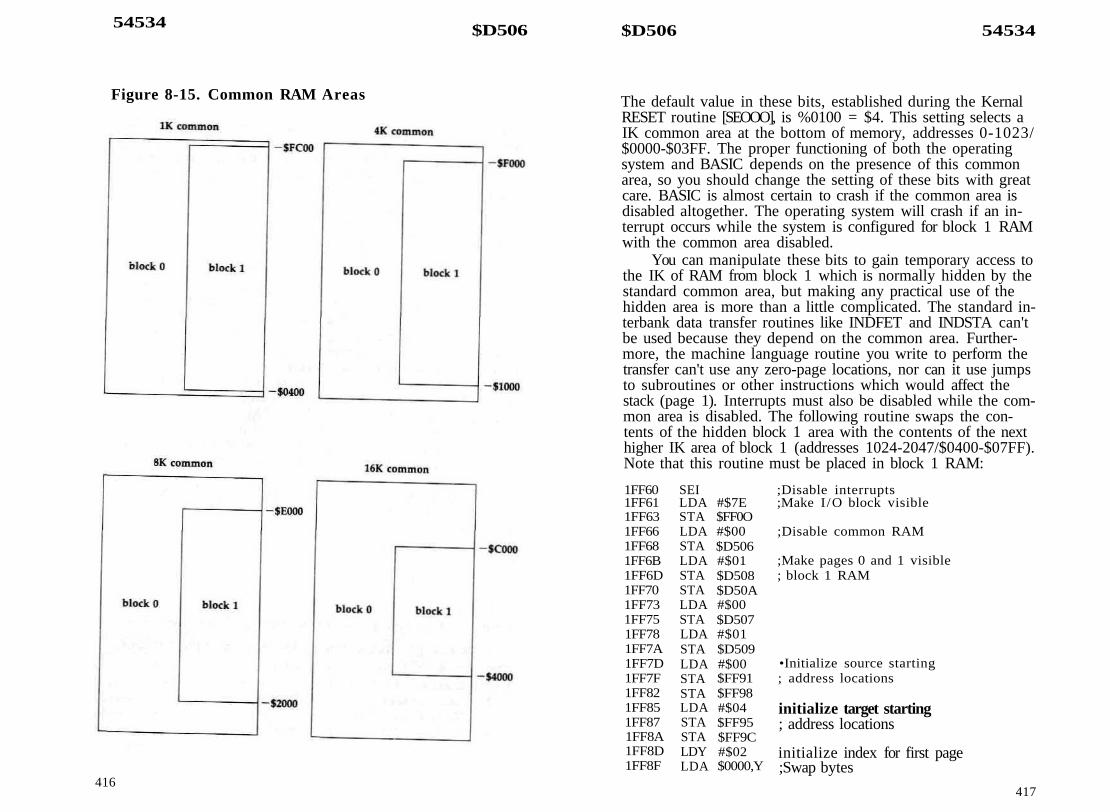
54534 $D506
Figure 8-15. Common RAM Areas
416
$D506 54534
The default value in these bits, established during the KernalRESET routine [SEOOO], is %0100 = $4. This setting selects aIK common area at the bottom of memory, addresses 0-1023/$0000-$03FF. The proper functioning of both the operatingsystem and BASIC depends on the presence of this commonarea, so you should change the setting of these bits with greatcare. BASIC is almost certain to crash if the common area isdisabled altogether. The operating system will crash if an in-terrupt occurs while the system is configured for block 1 RAMwith the common area disabled.
You can manipulate these bits to gain temporary access tothe IK of RAM from block 1 which is normally hidden by thestandard common area, but making any practical use of thehidden area is more than a little complicated. The standard in-terbank data transfer routines like INDFET and INDSTA can'tbe used because they depend on the common area. Further-more, the machine language routine you write to perform thetransfer can't use any zero-page locations, nor can it use jumpsto subroutines or other instructions which would affect thestack (page 1). Interrupts must also be disabled while the com-mon area is disabled. The following routine swaps the con-tents of the hidden block 1 area with the contents of the nexthigher IK area of block 1 (addresses 1024-2047/$0400-$07FF).Note that this routine must be placed in block 1 RAM:
1FF601FF611FF631FF661FF681FF6B1FF6D1FF701FF731FF751FF781FF7A1FF7D1FF7F1FF821FF851FF871FF8A1FF8D1FF8F
SEILDASTALDASTALDASTASTALDASTALDASTALDASTASTALDASTASTALDYLDA
#$7E$FF0O#$00$D506#$01$D508$D50A#$00$D507#$01$D509#$00$FF91$FF98#$04$FF95$FF9C#$02$0000,Y
;Disable interrupts;Make I/O block visible
;Disable common RAM
;Make pages 0 and 1 visible; block 1 RAM
•Initialize source starting; address locations
initialize target starting; address locations
initialize index for first page;Swap bytes
417

54534 $D506
1FF921FF931FF961FF991FF9A1FF9D1FF9E1FFA01FFA31FFA61FFA91FFAC1FFAF1FFB11FFB31FFB51FFB81FFBB1FFBE1FFCO1FFC31FFC5IFFC81FFC9
TAXLDASTATXASTAINYBNEINCINCINCINCLDACMPBCCLDASTASTASTALDASTALDASTACLIRTS
$04O0,Y$000O,Y
$O4O0,Y
$FF8F$FF91$FF95SFF98$FF9C$FF9C#$08$FF8F#$00$D508$D50A$D507#$01$D509#$04$D5O6
;Repeat for 256 bytes per page
increment address high bytes
;Check whether all four pages have; been swapped
;I( so, restore pages 0 and 1; to block 0 RAM
;Reenable common RAM
;Reenable interrupts
To execute the routine, use J 1FF60 from the monitor or BANK1:SYS 65376 from BASIC.
Bits 4-5: These two bits are not used in the current version ofMMU. The design specifications for the chip indicate that infuture versions these bits may be used in a "superbanking"scheme to select one of four separate 256K blocks of RAM in a1M (one-megabyte, or 1024K) system. It's a tantalizing pros-pect, but there's no guarantee that a Commodore 1024 willever be produced. In the current MMU, the bits will retainwhatever value is written to them, but changing the bitsettings has no effect on the memory configuration. The bitsare initialized during the Kemal RESET routine [$E000] to %00.Bits 6-7: These bits determine which 64K block of RAM theVIC video bank is located in. (See the section on the VIC chipearlier in this chapter for more information on video banks.)The formally defined selections for the bits are as follows:
418
$D5O8 54536
Bits70011
60101
RAM block forVIC video bank
0123
Remember, however, the 128 actually has only two 64Kblocks of RAM. Thus, the setting of bit 7 is meaningless, al-though that bit will retain whatever value you write to it.Only the setting of bit 6 matters, since the choice is betweenblocks 0 and 1. The default setting for these bits is %00, sincethe normal VIC text and bitmapped screens are located inblock 0 RAM.
You should note that the operating system and BASICwill not support a VIC video bank in block 1, That is, all thescreen editor ROM routines and BASIC bitmapped graphicsroutines assume that the VIC screen is located in block 0RAM, and will continue to write data to block 0 even afteryou've changed these bits to switch the video bank into block1 RAM. Thus, you must provide your own text and graphicsroutines for a display from block 1. For text displays, you canuse the standard character sets because the character ROM isstill visible in a block 1 video bank.
These bits actually determine the RAM block for all DMA(direct memory access) operations, not just for the VIC chip,but the VIC is the only built-in device in the 128 to use DMA.The only other commonly available DMA device for the 128 isthe REC (RAM expansion controller) chip in the 1700 and1750 Memory Expansion Modules. These bits, rather than bits6-7 of the configuration register, determine which block of128 system RAM is affected by REC transfer operations.
54535 8D507 MMUPOL54536 $D508 MMUPOHPage 0 pointersOne unique feature provided by the MMU is the ability to re-locate page 0 anywhere in memory. Zero page is the mostheavily used area of memory in any computer built around a6502-family microprocessor like the 128's 8502, since the pro-cessor has many instructions that are designed to work onlywith this page. Although neither the 128 operating system orBASIC makes use of this page-relocation capability, it has sev-
419

54536 SD508 SD50A 54538
eral interesting applications. For example, you could have sev-eral programs in memory simultaneously and give each itsown personal zero page, without having to worry about mem-ory conflicts.
Location 54535/$DF07, the page pointer, selects the pageof memory to which zero page is to be relocated. The KernalRESET routine [$E0O0] stores the value 0/$00 here to locatezero page initially in the true zero page. To move zero page,store the target page number here. {The page number is equiv-alent to the high byte of the first address in the page.) Actu-ally, the operation is more a swap than a relocation. Whenyou redirect zero page to another page of memory, all refer-ences to addresses in the target page are diverted to the truezero page. For example, if you store the value 19/$13 in thisregister to move zero page to page 19, then all references toaddresses in the range 2-255/$02-$FF will be redirected to4866-5119/$1302-$13FF, and all references to 4864-5119/$1300-$13FF will be redirected to 0-255/$00-$FF. Notice thataddresses 0-1 from zero page are not affected. These are theprocessor's on-chip I/O port registers—not RAM. Storing valuesin these locations always affects the registers rather than RAM.
Location 54536/$D508 selects the block of RAM in whichzero page will be seen. Only bit 0 of the block pointer is sig-nificant. Setting that bit to %0 selects block 0 RAM, while set-ting it to %1 selects block 1. The bit is set to %0 by the KernalRESET routine [$E000]. Bits 1-3 will retain whatever value iswritten to them, but changing these bits has no effect. The RE-SET routine sets these bits to %000, Bits 4-7 are also unused,but these bits always return %1 when read. As a result, thevalue in this register will always be at least 240/$F0. Valueswritten to the page pointer take effect immediately, but valueswritten to the block pointer are actually effective only after thenext time a value is stored in the page pointer. Thus, if youare changing both registers it is important to remember tostore the value in the block pointer (54536/$DF08) beforestoring the value in the page pointer (54535/$DF07).
However, the block pointer value is ineffective while theRAM configuration register (54534/$D506) is set to provide acommon area at the bottom of memory. With the bottom com-mon area enabled, zero page is always seen in block 0 RAM,although it can still be moved around freely within block 0.Since this is the default configuration for the 128, there is
420
rarely a need to change the value in 54536/$D508. If you se-lect block 1 RAM while the bottom common area is enabled, astrange effect results. Zero page is relocated to the page speci-fied in the page pointer, but that page is not swapped withzero page. That is, both pages will occupy the same area ofmemory, and the true zero-page area remains untouched.
When choosing areas of memory for a relocated zeropage, you must avoid page 1 (or the area where you relocatepage 1), since that page is also vital to proper system opera-tion. You should also avoid page 255/$FF, since attempting toplace zero page there will cause conflicts with the MMU regis-ters. Because all references to the target page will affect truezero page, you should be careful to avoid using any locationsin the target page while zero page is relocated (unless youreally want to change true zero page). After relocating zeropage, you will probably want to call the Kernal routinesRAMTAS [$FF87] and CINT [$FF81] to initialize importantzero-page locations. (If you switch to a zero page withoutproper screen editor variables, you may find yourself lookingat a garbled mess on the screen.)
54537 $D509 MMUP1L54538 SD50A MMUP1HPage 1 pointersJust as the MMU can relocate zero page, it also has the abilityto make page 1 appear anywhere in memory. Page 1 is vital inany computer built around a 6502-family microprocessor likethe 128's 8502, since that page is the processor stack. Thestack is the area of memory where the processor stores returnaddresses while it is executing subroutines or handling inter-rupts. The stack is also used extensively for temporary datastorage. Although neither the 128 operating system or BASICmakes use of this page-relocation capability, it has several in-teresting applications. For example, you could have severalprograms in memory simultaneously and give each its ownpersonal stack, without having to worry about memory conflicts.
Location 54537/$DF09, the page pointer, selects the pageof memory to which page 1 is to be relocated. The Kernal RE-SET routine [$E000] stores the value 0/$01 here to locate page1 initially in the true page 1. To move page 1, store the targetpage number here. (The page number is equivalent to the highbyte of the first address in the page.) Actually, the operation is
421

54538 $D50A 6D50B 54539
more a swap than a relocation. When you redirect page 1 toanother page of memory, all references to addresses in the tar-get page are diverted to the true page 1. For example, if youstore the value 21/$ 15 in this register to move page 1 to page21, then all references to addresses in the range 256-511/$0100-$01FF will be redirected to 5376-5631/$1500-$15FF,and all references to 5376-5631/$1500-$15FF will be re-directed to 256-511/$0100-$01FF.
Location 54539/$D50A selects the block of RAM inwhich page 1 will be seen. Only bit 0 of the block pointer issignificant. Setting that bit to %0 selects block 0 RAM, whilesetting it to %1 selects block 1. The Kernal RESET routine[$E000] sets this bit to %0 for block 0. Bits 1-3 will retainwhatever value is written to them, but changing these bits hasno effect. The bits are set by the RESET routine to %000. Bits4-7 are also unused, but these bits always return %1 whenread. As a result, the value in this register will always be atleast 240/$F0. Values written to the page pointer take effectimmediately, but values written to the block pointer are actu-ally effective only after the next time a value is stored in thepage pointer. Thus, if you are changing both registers it is im-portant to remember to store the value in the block pointer(54538/$DF0A) before storing the value in the page pointer(54537/$DF09).
However, the block pointer value is ineffective while theRAM configuration register (54534/$D506) is set to provide acommon area at the bottom of memory. With the bottom com-mon area enabled, page 1 is always seen in block 0 RAM—al-though it can still be moved around freely within block 0,Since this is the default configuration for the 128, there israrely a need to change the value in 54538/$D50A. If you se-lect block 1 RAM while the bottom common area is enabled, astrange effect results. Page 1 is relocated to the page specifiedin the page pointer, but that page is not swapped with page 1.That is, both pages will occupy the same area of memory, andthe true page 1 area remains untouched.
This mobile page 1 allows a tricky technique for fillingareas of memory. Instead of storing values in a series of loca-tions, you can redirect page 1 to the desired area of memoryand push values onto the relocated stack. The advantage ofthis is that the PHA instruction takes only half as long to exe-cute as the STA (address),Y instruction. Just be sure to pre-
serve the original stack pointer; otherwise, your program willcrash when the memory moving subroutine tries to return toits calling routine. The two routines below are alternate meth-ods of filling the high-resolution screen area. The conventionalmethod (on the left) is shorter, but the relocated stack method(on the right) is about 30 percent faster.BOO LDA #$00 COO TSX
STA $FB C01 STX $FBL D A #$20 C03 LDX #$FFSTA $FC COS TXSLDA #$FF C06 LDA #20LDX #$20 COS STA $D509LDY #$00 COB LDA #$FFSTA ($FB),Y COD LDX #$20INY C0F LDY #$00
B02B04B06BOSBOAB0CB0EB10Bll BNEB13 INCB15 DEXB16 BNEB18 RTS
$B0E$FC
$C11
Cl lC12C13C15CISC19C1BC1DC1EC20C23
PHAINYBNEINCDEXBNELDXTXSLDASTARTS
$C11$D509
$C11SFB
#$01$D509
$D50B MMUVER54539Version registerThis read-only register returns a constant value (much like aROM location) reflecting the amount of RAM in the systemand the version of the MMU. If Commodore ever introducessuccessors to the 128 built with similar system architecture (aCommodore 256 or 1024, for example), this register will allowsoftware to identify the amount of memory available.Bits 0-3: These four bits indicate the version of the MMU chipinstalled in the 128. In current 128s the value here is %0000= 0, indicating version 0 of the MMU, but this may change ifnew versions of the chip are introduced.Bits 4-7: These four bits indicate the number of 64K blocks ofRAM present in the system. In the 128, the value here is%0010 = 2, indicating 128K of RAM in two 64K blocks.
422 423

54540-54783 $D50C-$D5FF
54540-54783 $D50C-$D5FF UnusedAll the unused register addresses in this range return the value255/SFF when read. Writing to these locations has no effect.
65280 $FF00 MMUCRConfiguration registerThis is one of the most important locations in all of 128 mem-ory, since the value here determines what other memory ele-ments will be visible to the processor. The entire design of the128 is contingent on the MMU's ability to make various selec-tions of the system's memory resources visible at shared loca-tions within the processor's limited address space. The 16banks supported by the operating system are merely 16 pre-defined settings of this register—not 16 physical arrangementsof memory. See Table 1-1 in Chapter 1 for details of the stan-dard bank configurations.
Configurations other than the standard banks are certainlypossible. Since each of the eight bits of this register is assigneda function in the MMU specifications, there are theoretically256 possible different memory configurations. Actually, thereare only 128 functional combinations because bit 7 of the reg-ister in not implemented in the current version of the MMU.However, not all of these possible configurations are equallyuseful. For example, none of the configurations which involveeither internal or external function ROM are useful unless youhave a function ROM installed. The only configuration regu-larly employed by the system that doesn't correspond to astandard bank is one used by BASIC, consisting of BASICROM, screen editor ROM, character ROM, and Kernal ROM,plus block 1 RAM (essentially the same as bank 14, but withRAM from block 1 instead of block 0). Machine language pro-grammers may find it useful to set up a configuration whichswitches out BASIC ROM while retaining the I/O block andscreen editor and Kernal ROM, Such a configuration leaves 4IKfree for ML programs in the range 7168-49151/$1COO-$BFFF.To set up this arrangement, use LDA #$0F:STA $FFOO.
This location has an identical twin at address 54528/$D500. Actually, there is only one configuration register, but itcan be accessed at two different addresses. The higher addressis used almost exclusively because it is visible in all memoryconfigurations, whereas the register is visible at 54528/$D500only when the I/O block is selected (and you must have ac-
424
6FF00 65280
cess to the configuration register to make the I/O block visi-ble). Both registers will hold identical values, regardless ofwhich register is written to set the value.
There is an alternative to storing values directly in thisregister. You can store up to four configuration registersettings in the preconfiguration registers at 54529-54532/$D501-$D504, then transfer the values to the configurationregister by writing to the corresponding load configurationregisters at 65281-65284/$FF01-$FF04. See the precon-figuration and load configuration register entries for details.
Bit 0: This bit determines what is seen at addresses in therange 53248-57343/$D000-$DFFF. When the bit is set to %0,the I/O block (containing hardware chip registers and colorRAM) is visible. When the bit is set to % 1 , the contents of theaddress area is determined by the setting of bits 4-5.
Bit 1: This bit determines what is seen at addresses in therange 16384-32767/$4000-$7FFF. When the bit is set to %0,the lower portion of BASIC ROM appears there. When the bitis set to % 1 , the address area will contain RAM from the blockspecified in bits 6-7.
Bits 2-3: These bits determine what is seen at addresses in therange 32768-49151/$8000-$BFFF. The four possible selectionsare as follows:Bits3 2 Address range contents0 0 Upper portion of BASIC ROM ($8000-$AFFF), plus monitor
ROM ($BOOO-$BFFF)0 1 Internal function ROM1 0 External function ROM1 1 RAMInternal function ROM refers to ROM in the free ROM socketon the 128 circuit board. External function ROM refers toROM in a cartridge plugged into the expansion port. If you se-lect either of these sources when no ROM is actually installed,the area will appear to contain unpredictable changing values.When RAM is selected in this area, the block from which theRAM will be seen is determined by the setting of bits 6-7.
Bits 4-5: These bits determine what is seen at addresses in therange 49l52-65535/$C000-$FFFF, with some exceptions. TheMMU configuration and load configuration registers alwaysappear at 65280-65284/$FF00-$FF04, regardless of the
425

65280 $FF00 $FF04 65284
settings of these bits. Also, bit 0 of this register can overridethe specification for the contents of addresses in the range53248-57343/$D000-$DFFF. As long as bit 0 is set to %0, theI/O block will be seen in that portion of this area, regardlessof the setting of these bits. The four possible selections for thisarea are as follows:Bits5 40 0
Address area contentsScreen editor ROM ($COOO-$CFFF), character ROM($D00O-$DFFF), Kemal ROM ($EOOO-$FFFF)Internal function ROMExternal function ROMRAM
Internal function ROM refers to ROM in the free ROM socketon the 128 circuit board. External function ROM refers toROM in a cartridge plugged into the expansion port. If internalor external function ROM is selected when no ROM is actuallypresent, the area will appear to contain unpredictable chang-ing values. When RAM is selected, the area will contain RAMfrom the block specified in bits 6-7, unless the MMU's RAMconfiguration register at 54534/$D506 specifies a commonarea at the top of memory. When a common area is enabled,all RAM in the common area will come from block 0, regard-less of the block specified in bits 6-7.
Bits 6-7: The memory configuration established by the 128 al-ways includes RAM in the lowest 16K area (addresses2-16383/$0002-$3FFF), and RAM may be selected in any ofthe other three 16K segments in the processor's 64K addressspace. These bits determine which 64K RAM block the RAMin the selected configuration will be seen from. The formalspecifications for these bits are as follows:Bits7 6 RAM block selected0 0 Block 00 1 Block 11 0 Block 21 1 Block 3
Remember, however, that the 128 actually has only two 64Kblocks of RAM (blocks 0 and 1). Thus, the setting of bit 7 ismeaningless and has no effect in the current version of the
MMU. Bit 7 will retain whatever value you write to it, butonly bit 6 is significant.
The block specification in these bits will be overridden forcertain ranges of memory if any common RAM areas are spec-ified by the RAM configuration register at 54534/$D506.When common areas are enabled, any visible RAM in thecommon range will be seen from block 0, regardless of the set-ting of these bits.
These bits specify the RAM block for the processor only;the block in which the VIC (40-column) chip's video RAMbank is seen can be selected independently. The VIC block isspecified in bits 6-7 of the MMU's RAM configuration registerat 54534/$D506. The RAM configuration register bits, ratherthan the configuration register bits, also determine whichblock will be affected by other DMA (direct memory access)operations, such as data transfers by the REC (RAM expansioncontroller) chip in the RAM expansion modules.
65281 SFF01 LCRA65282 $FF02 LCRB65283 $FF03 LCRC65284 $FF04 LCRDLoad configuration registersEach of these registers has a corresponding preconfigurationregister at 54529-54532/$D501-$D504. Storing a value in aload configuration register causes the value in the precon-figuration register to be transferred to the configuration regis-ter. The value stored in the load configuration register isirrelevant; it is the store operation, rather than the valuestored, which causes the transfer. Reading any of the loadconfiguration register locations returns the value in the cor-responding preconfiguration register. Values stored in a loadconfiguration register location have no effect on the value re-turned when the register is read.
The 128 operating system does not use the preconfigur-ation or load configuration registers, but BASIC does. See theentry above for the preconfiguration registers for details of thestandard configuration settings.
426 427

54784-54785 $D600-$D601
VDC (Video Display Controller) ChipRegisters54784-54785/$D600-$D601The VDC (video display controller), officially designated the8563, is a custom chip designed by Commodore's engineersespecially to provide the 80-column display for the 128. TheVDC provides a digital RGBI signal requiring a special moni-tor, but other than that the fundamentals of its video displayare similar to those described for the VIC chip. The otherthing that distinguishes the VDC from the VIC is the VDC'shigh degree of programmability. Many of the features that arefixed in the silicon of the VIC can be customized on the VDCsimply by storing a value in one of its registers. For example,the VDC gives you complete control over the number of rowsand columns in the screen display, and even over the numberof pixels and scan lines in each character position.
Figure 8-16. VDC Memory ConfigurationS3FFF-
$3000-
$2000-
$1000-
$0800-
$0000- .
Lowerra se/uppercasecharacter set
Uppercase/graph iccharacter set
Unused
Attribute memory
Screen memory
428
6D600-$D601 54784-54785
Although the VDC does have a graphic mode (see the en-try for bit 7 of register 25/$19), it is primarily used for textdisplays. In this mode, it uses the same basic elements as theVIC: screen memory, character memory, and attribute memory(which corresponds to the VIC's color memory). However, allthese elements for the VDC appear in a 16K block of memorythat is totally separate from the 128's system address space.This separate block is reserved solely for the VDC. Figure 8-16illustrates the configuration of VDC memory.
VDC screen memory holds screen code values identical tothe screen codes for the VIC display. For each screen position,the screen code serves as an index into character memory toselect the pattern to be displayed in the position. All characterpatterns are in RAM. The VDC has no character ROM of itsown, so the contents of the VIC's character ROM is copiedinto VDC RAM during system initialization. Redefining char-acters for the VDC is as simple as storing the new pattern inthe proper area of character memory. Each character definitionis 16 bytes long, but because the default character height iseight scan lines, only the first eight bytes are used to holdcharacter pattern information. The remaining eight bytes aregenerally padded with zeros. To determine the starting ad-dress for the definition for any character, use the appropriateformula from the following:
for uppercase/graphics character set:address = (screen code * 16) + 8192
for lowercase/uppercase character set:address = (screen code * 16) + 12288
The remaining memory area is attribute memory, whichdetermines the display characteristics for the character speci-fied in screen memory. It is called attribute memory to distin-guish it from simple color memory because each attributememory location specifies more than just the color. Figure 8-17 shows the use of each bit of attribute memory.
The lower four bits specify the foreground color for thecharacter in the corresponding screen position. Unlike theVIC's color numbers, there is a strictly logical relationship be-tween the value in these bits and the resulting color. The RGBIin Figure 8-17 stands for red, green, blue, and intensity. For ex-ample, a value of %1000 in these bits selects only red, while
429

54784-54785 $D600-$D601
Figure 8-17. VDC Character Attributes
R G B I
character set(0 «• uppercase/graphics)(1 = lowercase/uppercase)
reverse(0 •" normal)(1 = reverse)
color (see Table 8-5)
flash (0 = off, J = on)
underline (0 — off, 1 — on)
%1011 selects red plus blue plus intensity, resulting in lightpurple. Table 8-5 shows the standard VDC color values. Notethat these values are different from the BASIC color numbers.
Table 8-5. Standard VDC Color Values
Value VDC color0/$00 blackl/$01 dark gray (light black)2/$02 dark blue3/$03 light blue4/$04 dark green5/$05 light green6/$06 dark cyan7/$07 light cyan8/$08 dark red9/$09 light red
10/$0A dark purplell/$0B light purple12/$0C dark yellow13/$0D light yellow14/$0E light gray (dark white)15/$0F white
Bit 4 selects the flash attribute, causing the character inthe corresponding character position to blink at the rate speci-fied in bit 5 of internal register 24/$18. Bit 5 selects the under-line attribute, but the line can be moved to any scan line ofthe character position. Bit 6 controls the reverse attribute,
430
SD600 54784
.̂ hich reverses the foreground and background pixels of thecharacter pattern. However, this attribute isn't used by the 128,which instead has reversed character patterns as part of the stan-dard character sets. Finally, bit 7 selects which of the two charac-ter sets will be used. The VIC allows only one of the twocharacter sets to be used at any one time, but the VDC allows
ju to select the character set independently for each characterposition.
The register structure of the VDC chip is rather unusual. Ithas only two registers visible in the normal system addressspace. You must go through these registers to access any of theinternal functions of the VDC. Table 8-6 lists the VDC communi-cations registers visible to the processor. A detailed description ofboth locations follows.
Table 8-6. VDC External Communications Registers
54784/$D600 VDC address/status register54785/$D601 VDC data register
54784 $D600 VDCADRAddress/status registerThe VDC actually has two different registers at this location: awrite-only address register and a read-only status register. Anyvalue you store in this location goes to the address register.The value specifies which one of the 37 internal VDC registerscan be accessed via the data register at 54785/$D601. Sinceonly six bits are needed to specify all the valid register num-bers (0-36), bits 6 and 7 of the address register are unusedand have no effect when you are writing to this register.
You can't read this location to determine which internalregister is being accessed; reading always returns the statusregister contents. The status register bits are defined asfollows:
Bits 0-2: These locations hold a constant number (like a ROMlocation) indicating the version number of the VDC chip cur-rently installed. There have been two versions of the VDC todate. In early 128s, the value here will be %000 = 0, while inlater models the value will be %001 = 1, The exact differencebetween the versions is not clear, but they do require slightlydifferent initialization. Specifically, internal register 25, the
431

54784 $D600 &D601 54785
' I
horizontal smooth scrolling register, requires different settingsfor the different versions. The IOINIT routine [$E109] checksthese VDC status register bits and performs the initializationaccordingly.
Bits 3-4: These bits are unused, and always return %0 whenread.
Bit 5: This bit, called the VBLANK flag, is used to indicatewhen the VDC raster scan is in its vertical blank period. Aftera full screen has been drawn and the electron beam has reachedthe lower right corner of the display, the beam must be turnedoff briefly while it is moved back to its home position in theupper left corner to begin the next frame. Otherwise, movingthe beam would result in a diagonal line across the screen.The time while the beam is turned off for this repositioning iscalled the vertical blanking interval. This bit, normally %0,will be set to %1 during the vertical blanking period.
When you're programming special screen effects, it'shandy to know when the blanking period is occurring. Thetime when one frame has been completely drawn but anotherone has not yet been started is a good time to change screenparameters without causing excessive flicker. The VIC chip cangenerate a raster interrupt to signal when its vertical blankinginterval is beginning, but the VDC chip can't generate inter-rupt requests, so this bit provides an alternate method of sig-naling that vertical blanking is in progress.Bit 6: This bit, known as the LP flag, is used to indicate whennew values have been latched in the internal light pen regis-ters. Whenever a pulse is detected on the VDC chip's LP inputline, the row and column positions of the raster beam at thattime are latched into internal registers 16—17/$10-$ll andthis bit is set to % 1 . This bit will remain %1 until one or bothof the internal light pen registers are read, at which time itwill be reset to %0. Thus, a %1 in this bit is a signal that anew light pen position can be read from the internal registers,while a %0 indicates that the register values have not changedsince they were last read. See the entry for internal registers16-17/$10-$ll for details of light pen reading.
Bit 7: This bit, known as the STATUS flag, is used to indicatethat the VDC is ready to read from or write to the internalregister specified by writing to the external address register.The flag bit will be set to %0 when a value is stored in this Io-
432
cation, and will return to %1 w h e n the specified register isready for access. The s tandard procedure for reading from orwriting to a VDC register is as follows;
Writing:LDX5TX
Reading:LDXSTX
WAIT LDXBPLLDA
#register number$D600$D600WAIT$D601
WAIT LDXBPLSTA
#register number$D600$D600WAIT$D601
Refer to the entry below for information concerning therestrictions on accessing this location from BASIC.
SD601 VDCDAT54785Data registerThis register is the gateway to the internal registers of theVDC. After you have set the desired internal register numberby writing to the address register at 54784/$D600, the speci-fied register becomes visible at this location. Reading from thislocation shows the internal register contents, and writing tothis location stores the value in the internal register. Once youspecify an internal register, that register remains visible hereuntil you change registers by storing a new value in 54784/$D600. Refer to the internal register descriptions below formore information on the effects of reading from and writing tothe various registers.
Commodore's specifications for this chip state that whenaccessing the VDC, you should avoid machine language in-structions that use the indirect addressing mode. That is, youshould avoid using instructions like LDA ($CC),Y to read thisregister because the VDC apparently responds improperly tosuch instructions. This imposes no particular hardship on ma-chine language programmers, but has highly unfortunate con-sequences for BASIC programmers. The 128's PEEK, POKE,and WAIT instructions are implemented using the KernalINDFET, INDSTA, and INDCMP routines, all of which use in-direct-Y addressing to read or store values. As a result, youshould not use PEEK, POKE, or WAIT statements to read orchange the contents of this location or of location 54784/$D600.
This would seem to make the VDC inaccessible fromBASIC. Fortunately, a pair of screen editor ROM routines pro-vide a simple detour around this roadblock. In Chapter 7 theyare designated WRITEREG [$CDCC] and READREG [SCDDA],
433

54786-55039 $D602-$D6FF
and they have the form shown above in the discussion of lo-cation 54784/$D600. To store a value in any VDC registerfrom BASIC, use:SYS DECCCDCC"), value, register
or
SYS 52684, value, register
where register is the number (0-36) of the internal VDC regis-ter you wish to access, and value is the value (0-255) youwish to place in that register. If you have used any otherBANK statements in your program, it would be wise to add aBANK 15 statement before these SYS statements to insure theproper memory configuration.
To read the contents of an internal VDC register fromBASIC, use a statement of the form:SYS DECC'CDDA"),, register : RREG A
orSYS 52698,, register : RREG A
Be sure you have two commas between the SYS address andthe register number. After this statement has been executed,the variable A will contain the value read from the specifiedregister. Again, if you change bank configurations elsewherein your program, it would be wise to add a BANK 15 beforethe SYS statement.
54786-55039 $D602-SD6FFVDC chip register imagesDue to incomplete address decoding, images of the VDC chipregisters appear repeatedly through the remainder of this pageof memory. That is, storing a value in any even-numbered lo-cation in this range has the same effect as storing a value in54784/$D600, and storing a value in any location in thisrange having an odd address has the same effect as storing avalue in 54785/$D601. It might be easier to remember the ad-dress of one of the image locations, such as 55000 in place of54784. Nevertheless, it's better programming practice to usethe officially designated register addresses.
434
$D600-$D601 54784-54785
VDC Internal RegistersTable 8-7 lists the various internal VDC registers which can beaccessed via the external communications register. A detaileddescription of each follows.
Table 8-7. VDC Internal Registers
0/$00 Total number of horizontal character positionsl/$01 Number of visible horizontal character positions2/$02 Horizontal sync position3/$03 Horizontal and vertical sync width4/$04 Total number of screen rows5/$05 Vertical fine adjustment6/$06 Number of visible screen rows7/$07 Vertical sync position8/$08 Interlace mode control register9/$09 Number of scan lines per character
10/$OA Cursor mode controlll/$0B Ending scan line foT cursor12/$0C Screen memory starting address (high byte)13/$0D Screen memory starting address (low byte)14/$0E Cursor position address (high byte)15/$0F Cursor position address (low byte)16/$10 Light pen vertical position17/$11 Light pen horizontal position18/$12 Current memory address (high byte)19/$13 Current memory address (low byte)20/$14 Attribute memory starting address (high byte)21/$15 Attribute memory starting address {low byte)22/$ 16 Character horizontal size control register23/$17 Character vertical size control register24/$18 Vertical smooth scrolling and control register25/$19 Horizontal smooth scrolling and control register26/$lA Fore ground/background color register27/$lB Address increment per row28/$lC Character set address and memory type register29/$lD Underline scan-line-position register30/$lE Number of bytes for block write or copy31/$1F Memory read/write register32/$20 Block copy source address (high byte)33/$21 Block copy source address (low byte)34/$22 Beginning position for horizontal blanking35/$23 Ending position for horizontal blanking36/$24 Number of memory refresh cycles per scan line
435

54784-54785 SD600-SD601
0 $00Total number of horizontal character positionsThe value in this register determines the total width (in char-acter positions) of each horizontal line of the display. Thevalue stored here should be one less than the desired numberof horizontal character positions. This total includes the activeportion of the display (where characters can be displayed), theleft and right borders, and the horizontal sync width. The totalnumber of horizontal pixels is given by multiplying the valuehere (plus 1) by the total number of pixels per character posi-tion (the value in bits 4-7 of register 22/$16 plus 1).
The default value for this register, established during theIO1NIT routine [$E109], is 126/$7E, This provides 127 hori-zontal character positions. You'll need to reduce this by half ifyou enable the pixel double feature (see the entry for bit 4 ofregister 25/$19). You may need to increase the value hereslightly if you use one of the interlaced modes.
1 $ 0 1Number of active horizontal character positionsThe value in this register determines how many of the hori-zontal character positions specified in register 0/$00 can actu-ally be used to display characters. The value stored hereshould be the desired number of columns for the display. Thevalue here must be less than the value in register 0/$00. Thedefault value for this register is 80/$50, since the default VDCdisplay is an 80-column text screen. The value here also deter-mines the width of the bitmap when the VDC is set for graphicmode. The bitmap width is given by multiplying the numberof character positions by the character-position width specifiedin bits 0-3 of register 22/$16.
The screen editor routines that support printing to the 80-column screen assume that each screen line occupies 80 screenmemory locations. If you want the screen printing routines tocontinue to function properly after you reduce the number ofactive character positions in this register, you should increasethe value in register 27/$lB so that the sum of the value inthat register plus the value in this register remains equal to 80.Reducing the value here removes characters from the right ofthe display area. To center the active display area after reduc-ing the number of character positions, you must reduce thevalue in register 2/$02. The screen editor routines will not
AP600-$D601 54784-54785
support a display wider than 80 columns, so you'll have towrite your own text handling routines if you want to use awider display.
2 $ 0 2Horizontal sync positionThe value in this register determines the character position atwhich the vertical sync pulse begins. The value here also de-termines the horizontal position of the active portion of thescreen within the total display. The default value here is102/$66. Increasing this value moves the active screen area tothe left; decreasing it moves the active area to the right.
3 $ 0 3Horizontal and vertical sync widthBits 0-3: These bits specify the width of the horizontal syncpulse. The value here should be one greater than the desirednumber of character positions for the pulse. The default valuefor these bits is 9/$9, for a pulse eight character positions wide.
Bits 4-7: These bits specify the width of the vertical syncpulse. The bit value here should be equal to the desired num-ber of scan lines for the pulse, unless the interlaced sync andvideo mode is being used (in that case, use a value that istwice the desired number of scan lines). The default value forthese bits is 4/$4, for a pulse four scan lines wide.
4 $04Total number of screen rowsThis register specifies the total height (in character positions)of the VDC display. The value stored here should be one lessthan the desired number of vertical character positions. Thetotal includes the rows for the active display, the top and bot-tom portions of the border, and the vertical sync width. To de-termine the height of the raster in scan lines, multiply thevalue in this register (plus 1) by the number of scan lines percharacter position (the value in register 9/S09 plus 1) and addany additional scan lines specified in register 5/$05.
The proper number of scan lines for the display is a func-tion of the video system being used; it's different for NTSC(North American) and PAL (European) systems. During theIOINIT routine [$E109], the 128 checks the VIC chip to deter-
436 437

54784-54785 $D600-$D601
mine which system is being used (since the VIC isn't pro-grammable like the VDC, there is a different version of theVIC for each of the two video systems). This register is theninitialized accordingly: to 32/$20 for NTSC systems or 39/$27for PAL systems, selecting 33 or 40 rows, respectively. Sincethe default character-position height is eight scan lines, the re-spective total heights are 33 * 8, or 264 lines, for NTSC, and40 * 8, or 320 scan lines, for PAL. These scan-line totalsshould remain constant, so if you increase the character heightyou must decrease the total number of rows, and vice versa.
5 $05Vertical fine adjustmentBits 0-4: The total number of scan lines in the VDC's videodisplay should be 264 for an NTSC (North American) systemor 320 for a PAL (European) system. The number of scan linesused in the VDC display is given by the total number of verti-cal positions (specified in register 4/S04) multiplied by thenumber of scan lines per character position (specified in regis-ter 9/$09). If the result doesn't come out exactly equal to therequired 264 or 320, the VDC can add a few extra scan lines atthe end to achieve the proper result. The value in this registerspecifies the number of extra scan lines to add. The availablefive bits allow up to % 11111 = 3 1 / $ i F additional scan lines.
The default character height of eight scan lines is an exactmultiple of both 264 and 320 (33 * 8 = 264 and 40 * 8 =320). Thus, no extra scan lines are required, so this register isinitialized to 0/$00 by the Kernal IOINIT routine [$E109]. Asan example of the use of this register, assume that you in-creased the character height to nine scan lines. For an NTSCsystem, 264 / 9 = 29 with a remainder of 3. Thus, for thiscase you should specify 29 for the total number of verticalcharacter positions and store a 3 in this register to provide therequired additional scan lines.Bits 5-7: These bits are unused; writing to them has no effect,and they always return %1 when read. Thus, the value youread from this register will always be at least 224/$E0. Tomask off these bits and see only the valid bits of the register,use AND 31 in BASIC or AND #$1F in machine language.
6D600-$D601 54784-54785
6 $06Number of visible screen rowsThe value in this register determines how many of the verticalcharacter positions specified in register 4/S04 can actually beused to display characters. The value here must be less thanthe total number specified in register 4/$04. The default valueestablished for this register by the Kernal IOINIT routine[$E109] is 25/$19, which sets up the standard 25-row display.One obstacle to selecting other numbers of rows is that thescreen editor ROM routines will, by default, assume a 25-linescreen. When decreasing the number of rows, you can makethe screen editor use the reduced number by storing a valueequal to the new number of rows minus 1 in location 237/$ED, then resetting the output window to full screen size (byprinting two cursor-home characters, for example). The screeneditor routines will not support a display with more than 25rows, so you'll have to provide your own character manipula-tion routines to use such a screen.
7 $07Vertical sync positionThe value in this register determines the vertical character po-sition at which the vertical sync signal will be generated. Thisregister can be used to adjust the vertical location of the activedisplay area within the screen. The default value for this regis-ter, established by the IOINIT routine [$E109], is 29/S1D forNTSC (North American) systems or 32/S20 for PAL (Euro-pean) systems. Decreasing the value here will move the activedisplay area down the screen, while increasing the value willmove the active display area upwards. However, you shouldnot increase the value here above the maximum number ofrows specified in register 4/$04.
8 $08Interlace mode controlBits 0-1: The value in these bits controls the interlace mode ofthe screen. The complete standard for NTSC video calls for aframe (raster) of 525 lines to be redrawn 30 times per second,while the PAL standard calls for 625 lines redrawn 25 timesper second. The full screen isn't drawn all at once; instead, it'sdrawn in two passes with half the lines for the frame drawnon each pass. The lines for the second pass of the frame are
439

54784-54785 $D600-$D601
drawn between the lines for the first. Like most computer dis-plays, the VDC normally takes a shortcut and draws half thefull number of lines at twice the rate. This noninterlaced dis-play provides sufficiently sharp output for most uses. How-ever, the VDC is also capable of producing two interlaceddisplay modes. The modes are selected as follows:BitsI 0 Value Interlace modex 0 0 or 2 noninterlaced0 1 1 interlaced syncII 3 interlaced sync and video
The default value is 0/$00, which selects the standardnoninterlaced mode. The system never uses any other mode.In the interlaced sync mode, the number of scan lines is dou-bled. Each horizontal scan line is drawn twice, once on thefirst pass and very slightly lower on the second pass. The re-sult should be greatly improved vertical resolution, but you'llprobably be disappointed. Remember that each tiny dot on thescreen glows only very briefly after being struck by the rastervideo beam. Since this mode must draw twice as many lines,it draws each line only half as often. On most video monitors,the first set of lines will have started to fade before the secondset is completely drawn. As a result, the screen will appear tojitter annoyingly in this mode.
The remaining choice is interlaced sync and video mode.In this case, the VDC also draws twice as many lines as non-interlaced mode, but the alternating half-frames are indepen-dent, so you can use twice as many horizontal lines per frame(the maximum screen height in scan lines is double that of thenoninterlaced mode). This creates the tantalizing prospect ofan 80-column X 50-line text screen. The following routinesets up such a display:
10 WR=DEC("CDCC")20 SYS WR,3,830 SYS WR,64,440 SYS WR,50 ,650 SYS WR,58,760 SYS WR,128 ,0
However, this setup does have limitations. It suffers from thesame jitter problems as the other interlaced mode. Further-more, the screen editor routines that control printing to the
440
$D600-$D601 54784-54785
screen will not support a display longer than 25 lines, soyou'll have to write your own text manipulation routines tohandle the extra 25. Nevertheless, this mode has interestingpossibilities.
Bits 2-7: These bits are unused; writing to them has no effect,and they always return %1 when read. Thus, the value youread from this register will always be at least 252/$FC. Tomask off these bits and see only the valid bits of the register,use AND 3 in BASIC or AND #$03 in machine language,
9 $ 0 9Total number of scan lines per characterBits 0-4: These bits determine the total vertical height (in scanlines) of each character position. The value stored here shouldbe one less than the desired number of scan lines. The totalvertical height value includes the scan lines for the active por-tion of each character position, plus any desired number ofblank scan lines for intercharacter vertical spacing. The heightof the active portion of the character position is determined bythe value in register 23/$17.
The default value for this register, established during theIOINIT routine [SE109], is 7/$07, for a total character-positionheight of eight scan lines. In this case, there will be no verticalintercharacter spacing because this is less than the active char-acter height. (In the default character set, intercharacter spacingis achieved by leaving the bottom row of the character patternblank.) The five available bits allow values up to %11111 =31/$IF, for character-position heights of up to 32 scan lines.However, when changing this value to allow for greater verti-cal resolution, you must keep in mind that the value here mul-tiplied by the total number of rows specified in register 4/$04(and plus the number of extra scan lines specified in register5/$05) determines the number of scan lines in the display.This total should always be 264 lines for NTSC (North Ameri-can) systems or 320 lines for PAL (European) systems.
The value here also determines how much memory is re-quired for character pattern memory. While the value here isless than or equal to 15 (while the character height is 16 orfewer scan lines), each character pattern is allocated 16 bytes.Since the VDC supports two complete 256-character sets, a to-tal of 512 * 16, or 8192 bytes, are required for character mem-ory' However, if the character height exceeds 16 scan lines (if
441

54784-54785 $D600-$D601 $D600-$D601 54784-54785
the value here is greater than 15), then 32 bytes are allocatedfor each character pattern. In this case, 512 * 32, or 16,384bytes, are required for character memory. Note that this is allthe memory available to the VDC.
Bits 5-7: These bits are unused; writing to them has no effect,and they always return %1 when read. Thus, the value youread from this register will always be at least 224/$E0. Tomask off these bits and see only the valid bits of the register,use AND 31 in BASIC or AND #$1F in machine language.
10 $0ACursor mode controlThe value in this register cannot be changed directly while thestandard screen editor ROM routines are used for printing.The contents of a shadow location at 2603/$OA2B are copiedto this register each time the cursor position is updated. Thus,to change the value in this register, you must store the desiredvalue in the shadow location rather than in the register.Bits 0-4: The value in these bits determines the scan linewithin each character position for the top of the cursor. Scanlines within character positions are numbered beginning with0 for the top line of the position. Bits 0-4 of register ll/$0Bdetermine the bottom line, and together these registers deter-mine the height of the cursor. The available five bits allowstarting row numbers as large as %11111 = 31/$1F. The de-fault value for these bits is %00000, to start the cursor at char-acter scan line 0, the top line of the character, for the standardfull-height block cursor. The operating system also supportsan underline cursor, selected by printing ESC U [$CAFE], Inthis case, the value here is changed to %00111 (7) to start thecursor on the bottom line of the standard character position.The value for the top scan line should be no greater than themaximum number of scan lines specified in register 9/$09, orelse the cursor will not be visible.
Bits 5-6: These bits control the type of cursor provided. Unlikethe VIC, where the cursor is an effect maintained by software,the VDC has hardware to generate a cursor automatically. Thepossible modes are as follows:
442
Bit values Cursor mode
0/$00 solid {nonblinking) cursor32/S20 no cursor64/$40 blinking at 1/16 screen refresh rate96/$60 blinking at 1/32 screen refresh rate
The default setting for these bits is %11, specifying a cursorblinking at the slower of the two rates. The operating systemalso supports a nonblinking cursor, selected by printing ESC E[$CB0B]. In this case, the bits are changed to %00. To rum thecursor off when the system is not accepting input (as when aprogram is running), these bits are reset to %01 [$CD9F].Bit 7: This bit is unused; writing to it has no effect, and it al-ways returns %1 when read. Thus, the value you read fromthis register will always be at least 128/$80. To mask off thisbit and see only the valid bits of the register, use AND 127 inBASIC or AND #$7F in machine language,
11 $0BBottom scan line for cursorBits 0-4: These bits determine the scan line within a characterposition for the bottom of the cursor. Together with bits 0-4of register 10/$0A, this serves to determine the height of thecursor. The value here should be one greater than the desiredbottom scan line (scan-line numbering starts with 0 for the topscan line of the character position). The five available bitsallow values up to % 11111 = 31/$1F, so the cursor can go aslow as scan line 30, However, the actual displayed cursorheight will never be greater than the character-position heightspecified in register 9/$09. The default value for this register,established by the IOINIT routine [$E109], is 7/$07, so thenormal bottom scan line of the cursor is scan line 6 of thecharacter position.Bits 5-7: These bits are unused; writing to them has no effect,and they always return %1 when read. Thus, the value youread from this register will always be at least 224/$E0, Tomask off these bits and see only the valid bits of the register,use AND 31 in BASIC or AND #$1F in machine language.
443

54784-54785 $D600-$D601
12 $0C13 $0DStarting address for screen memory
For standard text mode, the value in this register pair deter-mines the starting address for screen memory, the area whichholds screen codes specifying which character will be displayedin each screen position. The size of the screen memory area isdetermined by the number of active horizontal positions (spec-ified in register l/$01) multiplied by the number of active rows(specified in register 6/$06) and the address increment perrow (specified in register 27/$lB). The order of bytes for thepair is opposite that normally used in the 128 system: The firstregister (12/$0C) holds the high byte and the second (13/$0D)holds the low byte. Unlike VIC screen memory, which mustbegin on an even IK address boundary, VDC screen memorycan begin at any address in the VDC's address space. See Fig-ure 8-16 for a diagram of the VDC's memory configuration.
For graphic mode, the value in this register pair deter-mines the starting address for the bitmap of the graphicscreen. The amount of memory required for the bitmap isfound by multiplying the number of horizontal character posi-tions (from register l/$01) by the number of vertical characterpositions (in register 6/$06) times the total height of eachcharacter position (from register 9/$09 plus 1). The bitmapcan be started at any address in the VDC address space.
Even if you change the value here, the screen editor ROMroutines will continue to assume that screen memory is locatedin its default position unless you also change the value in thescreen memory starting-page pointer at 2606/$0A2E.
14 $0E15 SOFAddress of current cursor position
For the VIC chip's display, the cursor is an effect laboriouslymaintained by software. The VDC, by contrast, has hardwareto maintain the cursor for its display automatically. The cursorwill appear at the character position with the screen memorylocation specified in this register pair. If the address specifiedhere is outside the area of VDC memory currently being usedfor screen memory, no cursor will be visible. Other characteris-tics of the cursor such as its blinking status and position withinthe character are specified in registers 10/$OA and 11/$OB.
444
_ _ _
The value in these registers cannot be changed directlywhile the normal screen editor 80-column printing routines arein use. The printing routines update the cursor position aftereach character is printed so that these registers always holdthe address of the next available character position.
16 $1017 S l lLight pen vertical and horizontal positionsWhenever the LP input line to the VDC chip is brought to alow (0 volts) state, the row and column values for the currentposition of the raster beam are latched into these registers. Thevertical (row) number will be latched into register 16/$10, andthe horizontal (column) number will be latched into register17/$11. To signal that a value has been latched, the LP flag(bit 6 of the external register at 54784/SD600) will be set to%1. That bit will remain at %1 until either of these registers isread, at which time it will be reset to %0. However, readingthese registers does not clear them; the latched values will beretained until the LP line is brought low again.
The VDC's LP line is connected to pin 6 of control port 1(control port 2 does not support a light pen). A light pen hasat its tip an electronic device known as a phototransistor,which is connected so as to cause a low pulse whenever thevideo beam moves past the pen. Note that the pen will not betriggered if the screen position is black or one of the otherdark colors. Only positions which have bright characters canbe read. The ideal character to read with a light pen is a whitere verse-video space.
When a light pen is used, the range of values in theseregisters depends on the screen width and height selected byother VDC registers. Unlike the VIC chip, whose light penregisters return scan line and dot position values, these regis-ters return row and column numbers corresponding to thelight pen position. This makes the results much easier to inter-pret, but does not allow precise positioning, so it is unlikelythat you'll see any 80-column drawing programs using thelight pen as an input device. For the standard 80-column X25-line screen, the value in register 16/$ 10 corresponds veryclosely to the row number: ranging from l/$01 at the top ofthe screen to 25/$19 at the bottom. Actually, you may find
445

54784-54785 $D600-$D601 $D600-$D601 54784-54785
that if you position the pen slightly below the bottom screenline you can get a reading of 26/S1A.
While the vertical resolution is good, the horizontal reso-lution is quite poor. The horizontal reading won't correspondto the row number (1-80). Instead, it corresponds approxi-mately to the absolute horizontal character position, which in-cludes the border areas on the left and right edges of thescreen. You should find that when the pen is pointed at theleftmost character position, you get a reading of about 27-29in register 17/$11. This implies that the rightmost characterposition should give readings of about 106-108. Actually, youmay get higher readings—120 or more. In fact, even if youhold the pen perfectly stil] you may see the character positionvary up or down by 4 or 5. The moral is that the light pen ismuch better at reading vertical than horizontal positions.You'll have better luck if you limit yourself to checkingwhether the pen is within a range of horizontal positions. Forexample, if you read the horizontal position and store the re-sult in the variable H, then an expression such as H = INT({H— 30) / 8) will return a range of values 0-9 indicatingroughly which one of ten eight-column horizontal areas thepen is pointing to.
You should be aware that these registers can be trickedinto reading false values. Pin 6 of control port 1 is also usedfor light pen input for the VIC chip, and a light pen signalgenerated on the 40-column screen will latch meaningless val-ues in these registers. In lieu of a light pen, several otherevents can cause a pulse on the LP line. That control port pinis also used for the joystick fire button, so pressing the buttonof a joystick plugged into port 1 will also latch values in theseregisters. Because of this joystick button function, the port lineis also connected to the line from row 4 of the keyboard matrix.This has two consequences. First, pressing any of the follow-ing keys with no light pen connected will latch meaninglessvalues: Fl, Z, C, B, M, period, right SHIFT, space, the 2 andENTER keys on the numeric keypad, and the ^ key in thecursor group. More significantly, while a light pen is con-nected, all of these keys will be "dead," and cannot be typed.
446_
18 §J219 $13Current memory addressThis register pair specifies which address in the VDC's privateblock of RAM will be referenced by the next read or store op-eration involving register 31/S1F. As with the other VDC ad-dress register pairs, the first register (18/$12) holds the highbyte of the address and the second (19/$13) holds the lowbyte. A value stored in register 31/$1F is transferred to theVDC memory location specified in this register pair. Readingregister 31/$1F returns the value in the location in VDC mem-ory with the address specified in this register pair. For copy orfill operations, the value in these registers determines the des-tination address for the operation. These registers are auto-incrementing, meaning that the address value here is auto-matically increased by 1 after each read or store to register31/S1F. Thus, when you wish to read or load a continuous se-ries of VDC memory locations you only need to set the mem-ory address in these registers before the first read or store.After that, you can just read from or write to register 31/$1Fand the address will be handled automatically.
20 $ 1 421 $15Starting address for attribute memoryWhen attributes are activated, this register pair determines thestarting address for attribute memory, the area which holdsattribute values for each active character position on thescreen. (Attributes can be turned on and off by setting bit 6 ofregister 25/$19.) The size of the attribute memory area de-pends on the number of active rows and columns specified inregisters 2/$02 and 6/$06, and will be the same as the size ofthe screen memory area. See the discussion of attributes in theintroduction to this section for more information.
These locations are initialized to 2048/S0800, the defaultstarting address for attribute memory. Like the other addresspairs in the VDC, the first register (20/$14) holds the highbyte and the second (21/$15) holds the low byte. Attributememory can start at any address within the VDC's addressspace. Even if you change the value here, the screen editorROM routines will continue to assume that attribute memory
447

54784-54785 $D600-$D601 SP600-$D601 54784-54785
is in its default position unless you also change the value inthe attribute starting-page pointer at 2607/$0A2F.
22 $16Character horizontal size controlBits 0-3: The value in these bits determines how many of thetotal horizontal pixels in the character position will be used todisplay character pattern data. (The total number is specifiedin bits 4-7 of this register.) If the number of active pixels isless than the total number of pixels, the extra pixels will beblank for intercharacter spacing. If you specify a value herethat is greater than the total number of pixels available for theposition, only the specified total number of pixels will be visi-ble. However, the value here should not exceed 8, since amaximum of eight bits are available per byte of character pat-tern data. Even for values greater than 8, no more than eightpixels will be active per horizontal scan line within the charac-ter position. For graphic mode, the value here should be equalto the total number of pixels; otherwise there will be gaps inthe display.
The default value for these bits is 8, for eight active hori-zontal pixels per character-position scan line. This is the sameas the total number of pixels per position, so there will be nointercharacter spacing. (For the default character set, therightmost column of each character pattern is left blank to pro-vide the effect of intercharacter spacing,)
Bits 4-7: The value in these bits determines the width of eachcharacter position (in pixels). The value stored here should beone less than the desired total number of pixels. If the total isgreater than the number of active pixels specified in bits 0-3of this register, the extra pixels will be blank for intercharacterspacing. The default value for these bits is 7, for eight totalpixels per character position. The total number of horizontalpixels is determined by multiplying the value here (plus 1) bythe total number of character positions (from register 0/$00).
23 $17Character vertical size controlBits 0-4: The value in these bits determines how many of thetotal scan lines for each character position (specified in register9/$09) will be used to display character pattern data. The
available five bits allow you to specify values up to % 11111= 31/$1F. If the value here is less than the total number ofscan lines for the character position, the extra lines will beblank for intercharacter spacing. If the value here is greaterthan the total number of scan lines, only the total number ofscan lines will be displayed. For graphic mode, the value hereshould be at least equal to the total number of scan lines (thevalue in register 9/$09 plus 1); otherwise there will be gaps inthe display.
The default value stored in this register is 8/$08, for eightactive scan lines per character position. This is equal to the de-fault total number of scan lines for the position, so there willbe no intercharacter spacing. (For the standard character set,intercharacter spacing is achieved by leaving the bottom rowof most character definition patterns blank.)
Bits 5-7: These bits are unused; writing to them has no effect,and they always return %1 when read. Thus, the value youread from this register will always be at least 224/$E0. Tomask off these bits and see only the valid bits of the register,use AND 31 in BASIC or AND #$1F in machine language.
24 $18Vertical smooth scrolling and controlBits 0-4; These bits can be used to smoothly scroll the screenvertically upward. The value here specifies the number of scanlines the display should be shifted upward. Although five bitsare available, the value here should not exceed the value inregister 9/$09.
Bit 5: This bit controls the blinking rate for all characters onthe screen with the flash attribute. A character position has theflash attribute when bit 4 of its corresponding attribute mem-ory is set to % 1 . The two available blinking rates are onceeach 16 times the screen is refreshed (selected when this bit isset to %0) or once each 32 times (selected when this bit is setto %l). For NTSC (North American) systems, the screen is re-drawn 60 times per second, so the corresponding blinkingrates are about four times per second when the bit is %0 andabout twice per second when the bit is % 1 .
The default setting for this bit is % 1 , for the slower blink-ing rate. This is established during the IOINIT routine [$E109],
448 449

54784-54785 $D600-$D601 $D600-$D601 54784-54785
part of both the reset and RUN/STOP-RE STORE sequences.This setting is not changed by any other ROM routine.
Bit 6: This bit controls a special VDC feature known as reversemode. While this bit is %0, all pixels on the screen repre-sented by %0 bits in character patterns or the graphic screenbitmap take the background color specified in bits 0-3 of reg-ister 26/$lA, and all pixels represented by %1 bits take theforeground color specified in a corresponding attribute mem-ory location (or in bits 4-7 of register 26/$lA if attributes aredisabled). Setting this bit to %1 reverses the color sources, sothat all pixels for %0 bits take the foreground color and allpixels for %1 bits take the background color.
This bit is initialized to %0 for a normal screen display.The screen editor ROM supports escape sequences to changethis bit. The ESC R sequence will set the bit to % 1 , reversingthe screen display. The ESC N sequence will clear the bit to%0, returning the display to normal.
Bit 7: This bit determines whether the next block operationinitiated by writing to register 3O/$1E will be a copy or a fill.Setting this bit to %0 specifies a fill operation, while setting itto %1 specifies a copy operation. See the entry for register3O/$1E for more information on VDC block operations. Thisbit is set to %0 when the register is initialized during theIOINIT routine [$E109].
25 $19Horizontal smooth scrolling and controlBits 0-3: These bits can be used to smoothly scroll the screenhorizontally. The use of these bits depends on the version ofthe VDC in your 128. (The version number can be determinedby reading bits 0-2 of the external communications register at54784/$D600.) For version 1 of the VDC, which includes most128s, this register should be initialized to the maximum char-acter width (in bits 4-7 of register 22/$16). Each decrement ofthis register shifts the display one pixel to the left. For theolder version 0 of the VDC, these bits should be initialized to%0000. In this case, each increment of these bits shifts the dis-play one pixel to the right.
Bit 4: This bit controls the VDC's pixel double feature. Whilethis bit is %0, pixels will be their normal size. Setting this bitto %1 will double the size of all horizontal screen pixels. Since
450
each pixel is twice as large, there will be room for only half asmany on the screen. Thus, you must reduce the values in thehorizontal screen width registers (0-2/$00-$02) to half theirnormal values. The following routine sets up a VDC 40-columndisplay that will be very similar to the VTC's 40-column display:
10 WR=DEC("CDCC"):RR=DEC("CDDA")20 SYS WR,63,0:SYS WR,40,1:SYS WR,55,230 SYS RR,,25:RREG A:SYS WR,(A OR 16),2540 SYS WR,(8*16)+9,2250 SYS WR,40,2760 POKE 238,3970 PRINT"{2 HOMEllCLR}"
Bit 5: This bit controls a special VDC feature calledsemigraphic mode. When semigraphic mode is activated(when this bit is %1), the rightmost active pixel will be re-peated through the intercharacter spacing pixels. For thismode to have any visible effect, there must be someintercharacter spacing (the value in bits 0-3 of register 22/$16must be less than the total number of pixels specified in bits4-7 of that register). This mode has no effect in graphic mode.One use of this mode is to create a simple "digital" charactereffect. Try these lines:
SYS 52684,118,22SYS 52698,,25: RREG A: SYS 52684,(A OR 32),25Bit 6: The VDC has two methods of supplying foregroundinformation for its display. When this attribute enable bit is setto % 1 , each character position will have a correspondingattribute memory location. Refer to the introduction to thissection for details on attributes. The starting address of attributememory is determined by the value in registers 20-21/$14-$15, When this bit is %0, attribute memory is not used. In-stead, all character positions take the foreground color specifiedin bits 4-7 of register 26/$lA. In this case, the character posi-tions cannot have the flash, underline, or reverse attributes,and only the first of the two character sets will be available.
Bit 7: This bit determines whether the VDC will operate as atext or graphics display. Text mode, selected when the bit isset to %0, is the only one supported by the 128 operating sys-tem (%0 is the default value for this bit). In that mode, eachscreen memory position holds a screen code which serves as
451

54784-54785 $D600-$D601
an index into character memory to specify the pattern to bedisplayed in that position.
When this bit is set to %1 , graphics mode is selected. Inthat mode, screen memory is replaced with a bitmap. (There isno cursor on the graphic display.) Each bit in the bitmap con-trols the state of one pixel in the display. The layout of thebitmap is much simpler than that for'the VIC screen. Eachhorizontal scan line is controlled by a sequential series ofbytes. The size of the bitmap (in bytes) is determined by thenumber of active horizontal positions times the number of ver-tical positions times the number of scan lines per vertical posi-tion. For the standard screen setup, this means that 80 * 25 *8, or 16,000 bytes, are required—almost all of the availableVDC memory. At eight pixels per byte, there are 128,000 indi-vidual pixels on the graphic display.
The graphic display can use attribute memory for colorinformation. In this case, the relationship of attribute locationsto bitmap positions is similar to that for the VIC screen. Eachattribute memory location controls the color for all pixeiswithin a character-position area on the screen. However, thereisn't enough free memory available for a full bitmap and a fullattribute memory area. One solution is to turn off attributes(set bit 6 of register 25/$19 to %0). This limits all screen posi-tions to the same foreground and background colors (as speci-fied in register 26/$lA). The other solution is to reduce thesize of the active screen area to free up enough memory for anattribute area. For example, if you reduce the number of activerows to 22, then 80 * 22 * 8, or 14,080 bytes, will be requiredfor the bitmap, and 80 * 22, or 1760 bytes, will be required forattribute memory, so there will be enough room within VDCmemory for both bitmap and attributes.
When attribute memory is enabled for a graphic display,the lower four bits of each attribute memory location deter-mine the color of all foreground (%1) pixels in the correspond-ing character-position area, and the upper four bits determinethe color of all background (%0) pixels in the characterposition.
Program 8-1 is a very simple example of a bitmappeddrawing program for the VDC. Use a joystick in port 2 tosketch. Pressing the B key will change the background colorand pressing the F key will change the foreground color(attribute memory is turned off, so all character positions use
452
$D600-$D601 54784-54785
program 8-1. 80-Column Sketchpad
100 GRAPHIC 0:FAST110 WR=DEC("CDCC"):RR=DEC("CDDA")120 SYS RR,,25:RREG A:SYS WR,(A AND 63)OR 128,25130 SYS RR,,24:RREG A:SYS WR,A AND 127,24140 SYS WR,0,13:SYS WR,0,19:SYS WR,0,31150 FOR 1=0 TO 63:SYS WR,255,30:NEXT 1160 X=320:Y=100:BC=0:FC=15170 GET KS:ON INSTR( "BF{HOME HCLR j " , KS ) GOTO 180,1
80,160,140:GOTO 190180 BC={BC-(K?="B"))AND 15:FC=(FC-(K$="F"))AND 15:
SYS WR,FC*16+BC,26190 D=JOY(2) AND 15:IF D=0 THEN 170200 Y=Y+(D<3 OR D=8)-(D>3 AND D<7);IF Y<0 THEN Y=l
99:ELSE IF Y>199 THEN Y=0210 X=X-(D>1 AND D<5)+{D>5):IF X<0 THEN X=639:ELSE
IF X>639 THEN X=0220 AD=(Y*80)+INT(X/8):AH=INT(AD/256):AL=AD-(AH*25
6)230 SYS WR, AH ,18:SYS WR,AL,19240 SYS RR,,31:RREG A250 SYS WR,AH,18:SYS WR,AL,19260 SYS WR,A OR 2T(7-(X AND 7)),31270 GOTO 170
the same foreground and background colors). The CLR/HOME key can be used to move the drawing point back to itshome position in the center of the screen, and SHIFT -CLR/HOME will clear the display.
2 6 $ 1 ABackground and foreground colorsBits 0-3: The value in these bits determines the backgroundcolor of the display. For text mode, this is the color of allpixels represented by %0 bits in the pattern definition for thecharacter in each screen position. For graphic mode withattribute memory disabled, the value here determines the color°f all pixels represented by %0 bits in the bitmap. The cor-respondence between register value and background color isas shown in Table 8-5. For graphic mode with attribute mem-ory enabled, the value here determines the color of the screenborder only.
The default background color value, 0/$00 (black), is es-tablished by the Kernal IOINIT routine [$E109], part of boththe reset and RUN/STOP-RESTORE sequences. From BASIC,
453

54784-54785 $D600-$D601
the background color can be changed using the statementCOLOR 6, color number. However, the values for the color num-ber parameter are not the same as the color values shown inTable 8-5. Refer to the description of the COLOR statement inthe System Guide that came with your 128 for more information.
Bits 4-7: When attributes are disabled (by setting bit 6 of reg-ister 25/$19 to %0), the value in these bits specifies the fore-ground color for the display. For text mode, this is the colorfor all pixels represented by %1 bits in the pattern definitionsfor all screen positions. For graphic mode, the value here de-termines the color of all pixels represented by %1 bits in thebitmap. For either mode, if the screen is switched to reversemode (by setting bit 6 of register 24/S18), the value here willinstead determine the color for all pixels represented by %0bits in the character pattern or bitmap. The correspondencebetween bit values and colors is as shown in Table 8-5.
27 $1BAddress increment per row of charactersThe value in this register will be added to the value in register1/S01 to determine the amount by which to increase the screenmemory address for each new row of the display. This allowsyou to set up a virtual screen wider than the actual screen.You can scroll back and forth across the virtual screen by ad-justing the screen starting address in registers 12-13/$0C-$0D.
The default value for this register is 0/$00, since no extracolumns are used with the 80-column text display. The screeneditor routines that support printing to the VDC screen all as-sume an 80-column screen line. If you reduce the number ofactive columns in register l/$01, you should increase the valuein this register correspondingly so that the total remains 80.
28 $1CCharacter pattern address and memory typeBits 0-3: These bits are unused; writing to them has no effect,and they always return %1 when read. Thus, the value youread from this register will always be at least 15/SOF. To maskoff these bits and see only the valid bits of the register, useAND 240 in BASIC or AND #$F0 in machine language.
454
$D600-$D601 54784-54785
Bit 4: This bit specifies the type of RAM chip used for VDCvideo memory. When the bit is %0, the VDC is configured for4416 chips (16K X 4 bits). When the bit is % 1 , the VDC isconfigured for 4164 chips (64K X 1 bit). Since the 16K VDCvideo memory space in the 128 is provided by two 4416 chips,this bit is initialized to %0 by the Kernal IO1NIT routine[$E109]. It is theoretically possible to replace the existing chipswith the 64K variety to quadruple the amount of availableVDC RAM. However, the swap involves unsoldering the exist-ing chips from the circuit board and soldering the new ones intheir place. This is not a task for the inexperienced, and willmost certainly void any warranty on your 128.
Bits 5-7: These bits determine where within VDC memory thecharacter pattern definitions will be located. The amount ofmemory required for the character set depends on the value inregister 9/$09. If the character height is 16 or fewer scan lines,each character set requires 4K (4096 bytes). Character heightsof 17-32 scan lines require 8K (8192-b'yte) character sets. TheVDC normally supports a pair of character sets, using bit 7 ofthe attribute memory location to select between them for eachcharacter position. Thus, 8K is normally used for character setswhen the character height is 16 or fewer scan lines, and 16K isused when the character height is greater than 16 scan lines.In the latter case, bit 5 is not used in the address selection.The possible starting addresses for character patterns are asfollows (the asterisks indicate valid selections for 16K-characterset pairs):
Bits Character memory7 6 5 starting address0 0 0 0/$0000 *0 0 1 8192/$20000 1 0 16384/$4000 *0 1 1 24576/$60001 0 0 32768/$8000 *1 0 1 40960/SAOOO1 1 0 39152/SC0O0 *1 1 1 57344/$E000
Since the 128 has only 16K of RAM for the VDC, only thefirst two settings are currently valid. (Note that there is insuffi-cient room in the 128's 16K of VDC video memory for a 16Kcharacter set plus screen and attribute memory.) These bits areinitialized to %001 by the IOINIT routine [$E109], part of the
455

54784-54785 $D600-$D601
reset and RUN/STOP-RESTORE sequences, so the defaultcharacter set starting address is 8192/$2000. Since this area isRAM, not ROM, it is necessary to copy character patterns intothis area of memory if the VDC is to display recognizablecharacters. This step is performed during the IOINIT routineby calling the screen editor INIT80 routine [$CE0C].
29 $1DUnderline scan-line controlBits 0-4: The value in these bits determines which scan linewithin the character position will be filled for any characterswith the underline attribute. (A character position has the un-derline attribute when the corresponding attribute memory po-sition has bit 5 set to %1.) Since the line can appear on anyhorizontal scan line of the character position, it's not strictlycorrect to call it an underline. For example, you could movethe line to the top line of the position to be an overbar, or tothe middle line of the position to serve as an overstrike. Scanline 0 is the top line of the character position. The availablefive bits allow a maximum scan-line value of %11111 = 3 1 /$1F. However, the underline will not be visible if the value isgreater than the maximum character-position height in bits4-7 of register 22/$16.
Bits 5-7: These bits are unused; writing to them has no effect,and they always return %1 when read. Thus, the value youread from this register will always be at least 224/$E0. Tomask off these bits and see only the valid bits of the register,use AND 31 in BASIC or AND #$1F in machine language.
30 $1ENumber of bytes to copy or fillThe VDC has the capability to copy blocks of data up to 255characters long from one area of VDC memory to another, andto fill areas up to 255 bytes long with a specified value. Thevalue in this register determines the number of bytes to becopied or filled. The copy or fill operation begins immediatelyafter the count value is stored here. The setting of bit 7 of reg-ister 24/$18 determines whether the operation will be a copy
456
6n600-$P601 54784-54785
or a fill. The operations require different preparatory steps, asoutlined below:
For a fill operation:1. Set bit 7 of register 24/S18 to %0 to indicate a fill
operation.2. Load registers 18-19/$12-$13 with the starting address of
the area to be filled (the destination area).3. Store the value with which the area is to be filled in register
' 31/$1F. This will fill the first location.4. Store the number of bytes to be filled, minus one because of
the store performed in step 3, in register 3O/$1E. This willinitiate the block fill operation.
For a copy operation:1. Set bit 7 of register 24/$18 to %0 to indicate a fill operation.2. Load registers 18-19/$12-$13 with the starting address of the
area to be filled (the destination area).3. Store the value with which the area is to be filled in register
31/$1F. This will fill the first location.4. Store the number of bytes to be filled, minus one because of
the store performed in step 3, in register 3O/$1E. This will ini-tiate the block copy operation.
Either operation can be performed repeatedly to copy orfill areas larger than 255 bytes. The destination address regis-ters (18-19/$12-$13) and, for copy operations, the source ad-dress registers (32-33/$20-$21) increment automatically eachtime a location is copied or filled, so upon completion of onecopy or fill operation they will hold the address of the firstbyte beyond the area affected by the copy or fill. Thus, it isnot necessary to reload the address registers to copy or fillmore subsequent memory locations, nor is it necessary to setthe operation flag or to load the data register after the firstblock. (For multiple fill operations, the instruction above tosubtract 1 from the desired number of bytes to fill applies onlyfor the first block.)
31 $ 1 F
Memory read/writeThis register is the gateway between the VDC's private blockof RAM and the rest of the 128 system. When read, this
457

54784-54785 $D600-$D601
location reflects the contents of the VDC memory location ad-dressed in registers IS—19/$12—$13. Writing a value to thisregister will cause the value to be transferred to the locationaddressed in registers 18—19/$12—13. For both reading andwriting, the address in registers 18-19/$12-$13 will automati-cally be incremented after this register is accessed. Thus, toread or write a sequential series of locations you need onlyload the starting address of the series into registers 18—19/$12—$13. You can then read or write repeatedly to register31/$1F; the destination address will automatically incrementafter each read or write.
32 $2033 $21Source address for block copyThe VDC has the capability to copy blocks of data up to 255bytes long from one area of memory to another (see the entryfor register 3O/$1E for details). The value in this register pairdetermines the source address for copy operations, the addressfrom which data will be copied. Like all other address registerpairs in the VDC, the first register (32/$20) holds the highbyte of the address and the second (33/$21) holds the lowbyte—the opposite of the normal 8502 address format. Theregisters should be loaded with the desired source starting ad-dress before the copy operation is initiated. Upon completionof the operation, the registers will hold the address of the nextlocation beyond the last one involved in the operation. Thus,it is possible to copy blocks of more than 255 successive bytesby using repeated copy operations without reloading theseregisters.
34 $2235 $23Horizontal blanking positions
The VDC can adjust its horizontal blanking interval to blank aportion of the screen. These locations control the horizontalwidth and position of the blanked area. If the blanked area ex-tends onto the active portion of the screen, any text under theblanked area is only covered, not erased. The value in register34/$22 determines the rightmost blanked column, and thevalue in register 35/$23 determines the leftmost blanked col-umn. The blanked area extends the entire height of the screen.
458
fiP600-$D601 54784-54785
The value in register 34/$22 must be less than the valuein register 0/$00; otherwise, the entire display will beblanked. The value in 34/$22 here must also be greater thanthe value in register 35/$23 to prevent an entirely blank dis-play. The default values for these locations are 125/S7D and100/$64, respectively. This positions the blanking interval en-tirely outside the active screen area. For purposes of blankingan area of the screen, a value of 6/$06 in these registers corre-sponds to the leftmost column of the standard screen and avalue of 85/$55 corresponds to the rightmost column.
36 $24Number of memory refresh cycles per scan lineBits 0-3: The value in these bits determines the number ofmemory refresh cycles per scan line. The RAM chip used forthe VDC's video memory is a type known as dynamic RAM.A dynamic RAM can hold data only briefly without externalsupport. Just as the image on the video screen must be con-stantly redrawn to keep it from fading away, dynamic RAMmust be constantly refreshed to keep it from losing its con-tents. The VDC handles this refresh function automatically forits video RAM, just as the VIC automatically handles the re-freshing of system RAM. However, for the VDC, the numberof refresh cycles provided during each scan line is programma-ble. The IOINIT routine [SE109] initializes these bits to %0101for five refresh cycles per scan line, and there's no reason tochange that setting.
Bits 4-7: These bits are unused; writing to them has no effect,and they always return %1 when read. Thus, the value youread from this register will always be at least 240/SFO. Tomask off these bits and see only the valid bits of the register,use AND 15 in BASIC or AND #$0F in machine language.
37-63 $25-83F UnusedSince the external address register at 54784/$D600 allows asix-bit register number, these register addresses can also bespecified. However, none of these internal registers are used,and writing to them has no effect. All register numbers in thisrange return the value 255/$FF when read.
459

55040-55295 $D700-$D7FF
Unused I/O Area55040-55295/$D700-$D7FFThis area is described in Commodore literature as a reservedI/O expansion slot, but no currently available devices usethese locations. All locations in this area of the I/O block re-turn unpredictable changing values, and storing values herehas no effect.
VIC Color RAM5S296-56319/$D800-$DBFFWhen the I/O block is selected, this IK area holds color infor-mation for the VIC 40-column video chip. Unlike the otherportions of the I/O block, this area is RAM memory, not hard-ware chip registers. Since the VIC chip can generate only 16different colors, all possible color values can be specified injust four bits (0-15 - %0000-%llll). Thus, the RAM in thisarea does not consist of the usual eight-bit bytes, but rather offour-bit half-bytes, also called nybbles. When you read a loca-tion in this area, the upper four bits of the location's contentsare meaningless, random values which may be different eachtime the location is read. Those bits should be masked off todetermine the true color value (use AND 15 in BASIC orAND #$0F in machine language). When you store values inthese locations, only the lower four bits of the stored valuesare significant (POKE 55300,1 and POKE 55300,241 have thesame effect).
In the standard character display mode (GRAPHIC 0),each character position in screen memory has a correspondinglocation in this area which determines the color of the screendots drawn for any %1 bits in the character pattern specifiedfor that position. Since the screen background color shows inany %0 bits in the character pattern, the color specified incolor memory is referred to as the foreground color for thecharacter position. The colors resulting from the possible val-ues in these nybbles are as follows:
fen800-$DBFF 55296-56319
Value Color0/$00 blackl/$01 white2/$02 red3/$03 cyan4/$04 purple5/$05 green6/$06 blue7/$07 yellow8/$08 orange9/$09 brown
10/$0A light red11/$OB dark gray12/$0C medium gray13/$0D light green14/$0E light blue15/$0F light gray
The standard screen editor ROM routines for printing textto the 40-column display also set the color memory locationfor each character displayed. The color to be used is specifiedin location 241/$F1, the current foreground color. Wheneverthe output window is cleared—as when you print the {CLR}character, CHR$(147)—all locations in this area which corre-spond to character positions in the window will be filled withthe color specified in the lower four bits of location 241/$F1.Since the output window is reset to full screen size andcleared by the CINT routine [$C07B], part of both the resetand RUN/STOP-RESTORE sequences, either of those eventswill fill the first 1000 locations in this area, addresses55296-56295/$D800-$DBE7, with the default foregroundcolor value, 13/SOD (light green). The highest 24 addresses inthis area are not affected.
Multicolor Character Mode UsageFor multicolor character mode, each screen position has a cor-responding location in this area which serves two functions.Multicolor character mode is selected by setting bit 4 of theVIC register at 53270/$D016 to % 1 . In multicolor mode, eachcharacter is four dots wide by eight lines tall, and the dots canhave one of four colors. However, simply enabling multicolormode does not automatically specify multicolor mode for all
460 461

55296-56319 $D800-$DBFF
character positions. Multicolor mode must be selected on a po-sition-by-position basis. For each position, bit 3 of the colormemory location for that position specifies whether the positionwill behave like standard character mode or multicolor mode.
Setting bit 3 of a color memory location to %0 will makethe position behave as if standard character mode were stillactive for that position, except that only bits 0-2 of the colormemory location are then available to hold foreground colorinformation. Such positions are therefore limited to only 8choices for foreground color instead of the usual 16. Only thefirst 8 of the colors listed above are available, since using acolor value greater than 7 would put the position into multi-color mode.
Setting bit 3 of a color location to %1 selects multicolormode for that position. In that case, bits 0-2 of the color mem-ory location specify the color of any %11 bit pairs in the char-acter pattern specified for the position. Since only three bitsare available, only eight different colors can be selected. Thefirst eight of the standard colors (black-yellow) are the onlyones available, but since bit 3 must be set to %1 for multicolormode, the value you must store in color memory to get thesecolors is different from that used for standard character mode.You must add 8 to the normal color value. For example, tomake all %11 bit pairs in a character position white, you muststore the value 9 (8 + 1, the normal value for white). Com-modore's Programmer's Reference Guide states that the colorvalues still produce the standard colors, but this is not correct.For a multicolor mode position, storing a 9 in its color memorylocation makes the %11 bit pairs white, not brown.
Since the operating system does not specifically supportmulticolor character mode, clearing the output window whenthis mode is active has the same effect it does in standardcharacter mode—color memory is filled with the value fromthe current foreground color location (241/SF1).
Bitmapped Mode UsageThis area of memory is not used by the standard bitmappedmode (GRAPHIC 1). That mode gets all of its color infor-mation from video matrix locations. For multicolor bitmappedmode (GRAPHIC 3), values stored in this area control thecolor of those dots defined by %11 bit patterns in the bitmap.For the purposes of controlling color, the 160-dot X 200-line
anH00-$DBFF 55296-56319
multicolor bitmapped screen can be thought of as a grid of 4X 8-pixel blocks that is 40 blocks across and 25 blocks tall.Each block of dots in the grid has a corresponding color mem-ory location. The color of dots within the block which havethe same bit pattern is not independently selectable—all dotswith %11 bit patterns within the same 4-dot X 8-line blocktake the same color, the one specified in the color memory lo-cation for that block. The color memory locations can holdany of the 16 standard color values.
When the multicolor screen area is cleared with theBASIC statements GRAPHIC 3,1 or SCNCLR 3, all colormemory locations are filled with the value from location133/$85, the multicolor source 2 location. The default valuefor that location is 2, but that can be changed with theCOLOR statement. The GRAPHIC 4,1 or SCNCLR 4 state-ments should have the same effect, but they do not. The con-tents of color memory are not affected by either of thosestatements. Due to a bug in the SCNCLR routine [$6A79],color memory is filled for GRAPHIC modes 2 and 3 ratherthan 3 and 4. However, the fact that SCNCLR 2 unnecessarilyfills color memory has no obvious effect, since the standardbitmapped mode doesn't use color memory.
Color BanksThe 128 actually has two separate IK blocks of RAM availablefor this address area—a new feature not available in the Com-modore 64 (or in the 128's Commodore 64 mode). Normally,the 128 uses one block for character color and the other formulticolor bitmapped mode. This is why GRAPHIC 4 mode(split multicolor bitmapped and text) doesn't cause the con-flicts you might otherwise expect. That is, printing on the textscreen doesn't disturb colors on the multicolor bitmappedscreen, and drawing on the multicolor bitmapped screendoesn't disturb the colors on the text screen, even though bothappear to use the same color RAM.
The banking of color RAM is handled by the screen editorportion of the IRQ service routine [$C194j. Bits 0-1 of the8502's on-chip I/O port at location l/$01 determine whichblock of color RAM is visible in this address area (see the en-try for location l/$01 in Chapter 2 for details). Block 0 is nor-mally used for the multicolor bitmapped screen and block 1for the text screen. If you disable the screen handling portion
462 463

55296-56319 $D800-$DBFF fcnnO0-$DD0F 56576-56591
of the interrupt service routine, you can use this feature forother effects. For example, you can maintain two separatecolor displays for the text screen, or two separate text screens—each with its own color memory—or two separate sets of %11pixel color patterns for the multicolor bitmapped screen.
Program 8-2 shows one effect you can create with multiplecolor memory blocks for a single text screen. Line 110 selectsthe BANK 15 configuration (so that the I/O block, includingcolor RAM, will be visible) and stores the value 255 in thescreen mode flag to disable the screen handling portion of theinterrupt service routine. Remember that split screen modeslike GRAPHIC 2 and GRAPHIC 4 will not work while this por-tion of the interrupt service routine is disabled. Lines 130-150set up block 0 of color RAM, filling the screen borders with analternating pattern of black and white positions. Lines 170-190perform a similar setup for block 1, but using an alternatingpattern of white and black. Lines 210-230 set up screen mem-ory, drawing a border of ball characters around the screen.Lines 250-310 then switch between the two color blocks, pro-ducing a marquee effect as the border colors alternate.
Program 8-2. Color Bank Switching Demo
100 REM ** COLOR SWITCHING DEMONSTRATION110 BANK 15:POKE 216,255:REM DISABLE SCREEN INTERR
UPTS120 REM ** SET UP BLOCK 0 OF COLOR RAM130 POKE 1,PEEK(1) AND 254:PRINT"[CLR}"140 FOR 1=0 TO 39 STEP 2:POKE 55296+1,0:POKE 55297
+I,1:POKE 56256+1,0:POKE 56257+1,1:NEXT I150 FOR 1=0 TO lliPOKE 55336+(1*80),1:POKE 55375+{
I*S0),0:POKE 55376+(I*80),0:POKE 55415+(1*80),1:NEXT I
160 REM ** SET UP BLOCK 1 OF COLOR RAM170 POKE 1,PEEK(1) OR 1:PRINT"ICLRJ"180 FOR 1=0 TO 39 STEP 2:POKE 55296+1,1:POKE 55297
+I,0:POKE 56256+1,1:POKE 56257+1,0:NEXT I190 FOR 1=0 TO 11:POKE 55336+(1*80),0:POKE 55375+(
I*80),1:POKE 55376+(I*80),l:POKE 55415+(1*80),0:NEXT I
200 REM ** SET UP SCREEN MEMORY210 PRINT"{HOME}[3 DOWNJtRIGHT}tRVSJ PRESS ANY KEY
TO HALT DEMONSTRATION^ SPACES J "
464
220 FOR I = 0 T0 3 9 ! P O K E 1024+1,81 sPOKE 1984+1,81 -.NEXT I
230 FOR 1=0 TO 22:POKE 1064+(1*40),81:POKE 1103+(I*40),81:NEXT I
240 REM ** ALTERNATE COLOR RAM BLOCKS250 POKE 1,PEEK(1) AND 253260 FOR 1=1 TO 65JNEXT I270 GET A$:IF A$<>"" THEN 310280 POKE 1,PEEK(1} OR 2290 FOR 1=1 TO 65:NEXT I300 GET A$:IF A$="" THEN 250310 END
CIA (Complex Interface Adapter) ChipRegisters56320-56335/$DC00-$DC0F and56576-56591/$DD00-$DD0FThe CIA (complex interface adapter) chips perform the major-ity of the 128's input and output functions. Between them, theCIAs are responsible for handling communications with thekeyboard, joysticks, the serial bus (where disk drives andprinters are connected), the RS-232 port (where modems areconnected), and the user port. In fact—with the exception ofvideo output provided by the VIC and VDC chips and the au-dio output provided by the SID chip—the list of I/O functionsperformed by devices other than the CIAs is quite short: theVIC and VDC chips handle light pen input for their respectivedisplays, the SID chip reads paddle controllers (although aCIA reads paddle buttons and selects which pair of paddles isto be read), the processor's on-chip I/O port is used to controlsome aspects of tape data storage and to read the CAPS LOCKkey, and an MMU register line is used to read the 40/80 DIS-PLAY key.
All CIA registers are set to zero when the system RESETline is pulled low, as when the reset button is pushed. Most ofthe CIA registers are initialized during the IOINIT routine[$E1O9]. Table 8-8 lists the functions of the various CIA regis-ters. A detailed description of the use of each follows.
465

56320 SDC00
Table 8-8. CIA Chip Registers
CIA #1 CIA #256320/$DC00 56576/$DD00 Port A data I/O register56321/$DC01 56577/$DD01 Port B data I/O register56322/$DC02 56578/$DD02 Port A data direction register56323/$DC03 56579/$DD03 Port B data direction register56324/$DC04 56580/$DD04 Timer A latch/counter (low byte)56325/$DC05 56581/$DD05 Timer A latch/counter (high byte)56326/$DC06 56582/$DD06 Timer B latch/counter (low byte)56327/$DC07 56583/$DD07 Timer B latch/counter (high byte)56328/$DC08 56584/$DD08 Time-of-day dock (1/10 seconds)56329/$DC09 56585/$DD09 Time-of-day clock (seconds)56330/$DC0A 56586/$DD0A Time-of-day dock (minutes)56331/$DC0B 56587/$DD0B Time-of-day dock (hours)56332/$DC0C 56588/$DD0C Serial data register56333/$DC0D 56589/$DD0D Interrupt control register56334/$DC0E 56590/$DD0E Control register A56335/$DC0F 56591/$DD0F Control register B
CIA #1 RegistersThis CIA is used to read the keyboard, joysticks, and other de-vices connected to the control ports, such as the 128 mouse. Italso selects which pair of paddles will be read. The timers andFLAG input line are used in reading from and writing to tape.The chip's serial data communications hardware is used forfast serial bus I/O.
56320 SDC00 D1PRA56321 $DC01 D1PRBI/O port data registersThe CIA chip has two eight-line data ports, designated A andB. Each bit in the data registers is connected to one of the portlines (PA0-PA7 for port A and PB0-PB7 for port B). The linescan be either inputs or outputs, depending on the setting ofthe data direction registers (56322-56323/$DC02-$DC03). Forport B, bits 6-7 (lines PB6-PB7) can also have special timeroutput functions. See the discussion of the control registers at56334-56335/$DC0E-$DC0F for more information.
When a port line is set for input, its corresponding dataregister bit will reflect the state of the line. The bit will hold%0 when the line is pulled low (0 volts), or %1 when the lineis high ( + 5 volts). An unconnected input line, or one con-nected to a device that isn't actively pulling the line low, will466
SDC01 56321
"float" in a high state, and the corresponding data register bityn\\ hold a % 1 . Writing to a data register bit for an input linehas no effect on the state of the line, or on the value returnedwhen the bit is read. However, the value written to the bit willbe retained internally, and will determine the state of the lineif the line is changed to an output.
When a port line is set for output, its corresponding dataregister bit will control the state of the line. Setting the bit to%0 will pull the line to a low (0 volts) state, and setting thebit to %1 will allow the line to go to a high state (+5 volts).Note that string the bit to %1 doesn't guarantee that the out-put line will be set to a high state. The data CIA can force anoutput line low when an external device connected to the lineis trying to hold the line high, but it cannot bring an outputline high when an external device is holding the line low.Reading the data register bit for an output line returns the cur-rent state of the line (%0 if the line is low, or %1 if the line ishigh). Thus, a line set for output can still be used for a limitedform of input. If the data register bit for the output line is setto %1 , then reading that bit will return %1 while the outputline is high and %0 when an external device pulls the linelow. This explains how a joystick can be read from port A de-spite the fact that the lines of that port are normally config-ured as outputs.
Port B has a feature not available with port A. A specialhandshaking output line (from the CIA) designated PC, nor-mally high, will go low for one system clock cycle each timedata is read from or written to port B. This can be used to sig-nal an external device that data has been written or acceptedat the port. The PC line from CIA #1 is not connected to any-thing in the 128, but the PC line from CIA #2 is available atpin 8 of the user port.
For CIA #1, all port A lines are normally configured asoutputs and all port B lines are normally configured as inputs.This is to set up the lines for their primary function—readingthe keyboard. Refer to Figure 7-1 and the discussion of thekeyboard-scanning routine [$C55D] in Chapter 7 for more de-tails on how these lines are used for that purpose.
The second major function of these ports is to read thestatus of digital controllers connected to the two control ports°n the side of the 128. Each control port is connected to fivelines of one of the CIA #1 ports. Port B is connected to control
467

56321 $DC01 $DC01. 56321
port 1 {the front one) and port A to control port 2 (the backone), which is the opposite of what you might expect. Theconnections are as follows:
CIA port bit01234
Controller port pin12346
Joystick functionupdownleftrightbutton
The control port pins are usually described in terms oftheir joystick functions, since the joystick is the device mostcommonly connected to the ports. A joystick is a very simpledevice consisting of five switches, one for each of the four pri-mary directions and one for the fire button. The switches arenormally open, meaning that no connection is made when thejoystick is not being pressed. Remember that unconnected CIAport lines float to a high state ( + 5 volts), so the correspondingCIA port bits will be % 1 . Pressing the stick in one of the eightpossible directions (four primary directions and four diagonals)closes one or two of the switches, grounding the CIA portlines and forcing the corresponding bit or bits to %0. Pressingthe fire button grounds that line, so it is possible to have asmany as three lines simultaneously grounded.
For reading the joysticks, BASIC provides the JOY func-tion [$8203], which returns a value from 1-7, depending onthe direction the stick is pressed (the value is 0 if it is not be-ing pressed), with 128 added if the fire button is pressed. Toread the joystick from machine language, you simply read thecorresponding CIA port data register and check for %0 bits.Even though the port A lines are normally set up as outputs,you can still read the joystick without switching the lines toinputs. The keyboard scan routine leaves all port A bits exceptbit 7 set to % 1 , so it is still possible for external devices likethe joystick to pull the lines low (bit 7 of that port will nor-mally always be %0). The possible port readings are as follows:
o r t lSDC01)255/SFF254/SFE253/$FD251/SFB250/$FA249/$F9247/$F7246/$F6245/$F5
ControlCIA port A
%oiinm%01111110%01111101%01111011%01111010%01111001%omom%01110110%onioioi
port 2. ($DC00)127/$7P126/S7E125/$7D123/$7B122/S7A121/579119/$77118/$76117/$75
Joystickdirectionnot pressedupdownleftup + leftdown + leftrightup + rightup + left
$11111111fciiiiino%11111101ftllUlOll£11111010£11111001%iinom#11110110%11110101
If the fire button is pressed, bit 4 of the data register will alsobe set to %0, and the values listed above will be reduced by16/$10.
If you'd prefer to read %1 bits instead, try the followingcode:Control port 1
LDA $DC01AND#$1FEOR #$1F
Control port 2LDA $DC00AND #$1FEOR #$1F
Using this method, the accumulator will hold one of the fol-lowing values after the port is read:
Value Joystick direction0/$00 not pressedl/$01 up2/$02 down4/$04 left5/$05 up + left6/$06 down + left8/$08 right9/$09 up + right
10/$00 down + right
Pressing the fire button will add 16/$10 to any of the valueslisted above.
You should be aware, however, that using control port 1(CIA port B) for joystick input can have an undesirable side ef-fect. Since the input lines of that port are also used for readingthe keyboard, the keyscan routine [$C55D] has no way to tellwhether the port lines are being grounded by keypresses or
468 469

56321 $DC01
joystick presses. As a result, moving a joystick effectively gen-erates a keypress, and certain keypresses produce the same ef-fect as moving the joystick:
Joystick conflicts Keyboard conflictsDirection Effective keypress Keypress Effective directionup ALT 1 updown SHIFT-INST/DEL - downleft RETURN CONTROL leftright cursor left 2 rightfire SHIFT-F7 space fire
Many programs avoid this problem by using only port A(control port 2), which is the simplest solution. Because theport A lines are outputs, the joystick is never mistaken for thekeyboard in control port 2. You can prevent the keyboard con-flicts by disabling interrupts and forcing all keyboard columnlines high before reading the port (add SEI:LDA #$FF:5TA$DC00:STA $D02F before the LDA $DC01 instruction, andCLI after it). The joystick conflicts are more difficult to pre-vent—there is no way to disable the joystick. If your programdoesn't require keyboard input, a rather inelegant solution isto simply zero the count of keys in the buffer and pendingfunction key characters (locations 208/$D0 and 2O9/$D1)before exiting from the program.
Any device which behaves like a joystick can be read inthe same manner. This includes trackballs and the new mousecontrollers (which are more or less upside-down trackballs).Devices such as paddles or graphics tablets are analog, notdigital, devices, and are read by the SID chip. (See the entryfor the SID registers at 54297-54298/$D419-$D41A.) How-ever, any buttons on these devices are read as if they werejoystick lines. For example, the two buttons on a standard pairof Commodore paddles are read exactly like the joystick left-and right-direction lines for the corresponding control ports.Since the CIA ports are bidirectional, you could also use thecontrol port lines in interfacing projects. Together they provideten lines which can be either inputs or outputs.
The final function of these CIA ports is that bits 6-7 (linesPA6-PA7) of port A control which control port will be con-nected to the SID lines for reading paddles. Since paddlescome in pairs and the 128 has two control ports, you can con-nect up to four paddles. However, the SID has only two pad-dle inputs. As a result, you can read paddles from only oneport at a time. Valid selections are as follows:
470
SDCO3 56323
Control port selected
The other combinations result in either both or neither portsbeing selected. The port A lines are always outputs, so there isno problem with using them for this purpose. The defaultvalue in port A (except during the IRQ, when it is being usedto scan the keyboard) is 127/$7F. This has the bits set to %01,selecting control port 1. Unless you really need four paddles,it's best to use this port. To write any value other than127/S7F into port A, you must disable interrupts, since thekeyboard-scanning routine always leaves the port set to thatvalue.
Another bit of 128 hardware trivia: Our experienceindicates that a CIA #1 failure is one of the most commonhardware problems the 128 owner is likely to experience. Inte-grated circuit chips like the CIA are very sensitive to electricdischarges such as the static electric spark you see when youtouch a doorknob after shuffling across a carpet. Since thecontrol port lines lead directly to the pins of CIA #1, touchinga control port pin when your body carries a static charge islike a lightning strike to the chip. Unfortunately, since thecontrol ports lie so close to the reset and power switches, it'svery easy to touch them unintentionally, especially controlport 2. Of the five 128s we have had at COMPUTE! Publica-tions to date, three have experienced "blown" CIAs. Bit 1 ofport A seems to be particularly susceptible. This is in keepingwith our experience with Commodore 64s over the past sev-eral years, where we have lost approximately a dozen CIAchips out of about 30 computers. If one joystick direction or agroup of keys suddenly becomes impossible to read, a blownCIA is the likely source. To prevent this, some users resort tocovering the control ports with masking or electrical tapewhen the port is not in use. Another solution is to leave thejoystick plugged in at all times.
56322 8DC02 D1DDRA56323 SDC03 D1DDRBData direction registersEach of the eight lines in the CIA's two data ports can be indi-vidually configured as either an input or an output. These data
471

56324 $DC04
direction registers (DDRs) specify the direction of data flow onthe port lines. Each register bit corresponds to one port line(PA0-PA7 for port A and PB0-PB7 for port B). Setting a regis-ter bit to %0 makes the corresponding port line an inputwhile setting the bit to %1 makes the line an output. The linesare read and controlled by the data registers at 56320-56321/$DCOO-$DC01. For lines PB6-PB7 of port B, the settings ofbits 6-7 of 56323/$DC03 can be superseded when those linesare used for their special timer output functions. See the dis-cussion of the control registers at 56334-56335/$DC0E-$DC0Ffor more information.
For CIA #1, the IOINIT routine [$E109]—part of both thereset and RUN/STOP-RESTORE sequences—initializes theport A DDR (56322/$DC02) to 255/$FF, making all port Alines outputs, and the port B DDR (56323/$DC03) to 0/$00,making all port B lines inputs. These settings are not changedby any other ROM routines. You can change these settingsbriefly for special I/O functions involving the control ports,but leaving any port A lines set as inputs or port B lines set asoutputs will disable normal keyboard functioning. See the dis-cussion of the data registers above for more information onthe uses of the port lines.
D1T1LD1T1H
56324 $DC0456325 $DC05Timer A latch/counter registers
Timer A is a programmable counter that can provide a varietyof timing functions. It is a countdown timer, meaning that itrepeatedly decrements the counter contents until the value isdecremented below zero, a condition known as underflow.When Timer A underflow causes an internal CIA interrupt, bit0 of the CIA interrupt register at 56333/$DC0D will be set to% 1 . The timer can be set to count down repeatedly or justonce. The timer countdown can be driven by either of twosources: the system clock frequency or a signal provided onthe CNT line by an external device. The operating conditionsof the timer are specified in the CIA control register A(56334/$DC0E).
When read, the registers here return the current value inthe 16-bit counter (low byte in 56324/SDC04 and high byte in56325/$DC05), Data written to these registers does not go di-rectly into the counter unless the timer is currently stopped.
472
6PC07 56327
Instead, the values are held in an internal latch register. Thelatch contents are transferred into the counter whenever thetimer underflows. Alternatively, a bit in the control registercan force an immediate transfer of the latched value into thecounter.
One special function of timer A is to control the rate ofdata output over the CIA's serial port (SP) line. In this case,timer A generates a clock signal that is provided as an outputon the CNT line. Since timer A must underflow twice to pro-duce the full clock cycle on the CNT line required for each bit,you should load timer A with a value which will produce anunderflow in half the time desired for each bit. In other words,the duration of each bit transmitted on the serial line will betwice the time required to count down the value specified inthe timer A latch. See the entry for the CIA serial data register(56332/$DC0C) for more information on the CIA's serial dataI/O capabilities.
For CIA #1, timer A can be a source of IRQ interrupts tothe processor. This feature is used during tape I/O to generatethe IRQ interrupts which drive the reading and writing ofdata. CIA #1 timer A also controls the transmission rate fordata sent over the fast serial bus. Thus, if you use the timerfor your own timing applications, you should be aware thatboth tape and fast serial operations will change the settings ofthe timer. (The timer will be stopped upon completion of anytape or fast serial operation.) The IOINIT routine [$E109] callsthe Kernal fast serial output setup routine, which starts thetimer counting down from $0004, but then immediately callsthe fast serial input setup routine, which halts timer A. Thus,upon completion of the reset or RUN/STOP-RESTORE se-quence, the timer will contain some very low value: usuallyeither $0001 or $0002. Unlike the Commodore 64, CIA #1timer A is not the source of the 128's normal jiffy IRQ inter-rupts. That task is instead performed by raster interrupts fromthe VIC chip.
56326 $DC06 D1T2L56327 $DC07 D1T2HTimer B latch/counter registersThe operation of timer B is quite similar to that describedabove for timer A, but is a bit more flexible. In addition toc°unting system clock and CNT pulses, timer B can also count
473

56328 $DC08 SDCOB 56331
timer A underflows. This effectively ties the two timers to-gether to form a 32-bit countdown value, allowing countdownintervals of up to 70 minutes. The operation of timer B is con-trolled by the register at 56335/$DC0F.
For CIA #1, the IOINIT routine [$E109], part of both thereset and RUN/STOP-RESTORE sequences, loads the latchfor this timer with 65535/$FFFF and starts the timer runningin continuous mode. There is no obvious reason for this step.The only use of timer B by 128 ROM routines is during tapeI/O, where it is used to generate IRQ interrupts to drive thereading and writing of data. Upon completion of a tape opera-tion, the timer will be left halted and set for one-shot mode.
56328 SDC08 D1TOD156329 $DC09 D1TODS56330 $DC0A D1TODM56331 $DC0B D1TODHTime-of-day clock registersThe time-of-day (TOD) clock is a special feature of the CIA. Itkeeps time in hours, minutes, seconds, and tenths of sec-onds—units more useful to humans than the jiffies of the sys-tem software clock or the fractional microseconds of timer Aor B. There are actually two sets of registers at these locations,the time and the alarm. By storing an alarm value here, youcan trigger an internal interrupt (and, optionally, an externalIRQ request) when a specified time is reached. When you readthe registers, you always see the time value (the alarm settingis never visible). When you're writing to the register, bit 7 ofcontrol register B (56335/SDCOF) determines whether thevalue being written will set the time or the alarm.
The time is kept in 12-hour format, with bit 7 of thehours register used as a flag to indicate AM or PM. The timedata in the registers is in binary coded decimal (BCD) format.In this format, each half-byte (nybble) contains a value whichrepresents one decimal digit. For example, if the minutes regis-ter contains the value %00100110, equivalent to 38/$26, theminutes digits should be interpreted as 2 and 6—26 minutespast the hour, rather than 38 minutes. The register bits shouldbe interpreted as follows:56328/$DC08: Bits 0-3 hold the 1/10-seconds digit. Bits 4-7are unused. Writing to those bits has no effect, and they al-ways return %0 when read.
474
56329/$DC09: Bits 0-3 hold the ones digit for seconds. Bits4_6 of this register hold the tens digit (only three bits areneeded, since this digit will never be greater than %101 =5 the seconds count rolls over to $00 after reaching $59.) Bit7 is unused. Writing to that bit has no effect, and it always re-turns a %0 when read.56330/$DC0A: Bits 0-3 hold the ones digit for minutes. Bits4-6 hold the tens digit. Bit 7 is unused. Writing to that bit hasno effect, and it always returns a %0 when read.
56331/$DC0B: Bits 0-3 of this register hold the ones digit forhours. Bit 4 holds the tens digit for hours (only one bit isneeded, since this digit will always be either 0 or 1). Bits 5-6are unused. Writing to these bits has no effect, and they al-ways return %0 when read. Bit 7 is the AM/PM flag. The 12-hour format time value is taken to represent AM (midnight-noon) when this bit is %0 and PM (noon-midnight) when thebit is % 1 . Be sure to remember this bit when setting an alarmtime.
The order in which you read and write these registers isimportant. When reading the clock, the registers latch (remainconstant) after you read the hours register until you read fromthe 1/10-seconds register. The clock continues to count inter-nally; only the register values remain constant. Thus, eachread of the hours register must be followed by a read of the1/10-seconds register, even if you don't care about the 1/10-second value. Likewise, the clock stops whenever a value iswritten to the hours register, and does not start again until avalue is written to the 1/10-seconds register. Thus, for bothreading and writing you should start with the hours registerand end with the 1/10-seconds register.
The following routine illustrates the use of the time-of-day clock by displaying the current time in the upper left cor-ner of the screen:
i
D00D02D05D07D0ADOCDflF
LDASTALDASTALDASTALDA
#$89$DC0B#$05$DC0A#$00$DC09#$00
;Load clock registers with desired; initial time. (This example uses; 9:05:00.0 PM)
475

56331 $DCOB $DCOC 56332
;Gock starts when this register is written;Read hours byte (this latches the time value);Add either an A or a P to the time string,; depending on the state of the AM/PM bit
,Mask off the AM/PM bit;Convert the hours byte to two characters;RepIace leading zero with a space
;Add hours-digit characters to string
;Read minutes byte;Convert to two characters;Add minutes-digit characters to string
;Read seconds byte;Convert to two characters;Add seconds-digit characters to string
;Read 1/10-seconds byte (to unlatch time);Print time string;Repeat indefinitely
;Convert BCD byte to two ASCII characters;Stash the byte;Mask off all but the lower four bits;Add base ASCII numeral value;Leave low digit in X register;Retrieve original value;Move high four bits into low nybble
;Add base ASCII numeral value
;Print time string using Kernal PRIMM3A 30 30 3A ;String characters:4D 20 00 ; {HOME}{RVS}00:00:00 AM
Neither CIA's time-of-day clock is used by 128 mode, al-though CP/M does make use of the CIA #1 dock for time-keeping. None of these registers is initialized by any 128 ROM
476
D l lD14D17D19DIBDIDD1FD22D24D27D29D2BD2DD30D33D36D39D3CD3FD42D45D48D4BD4ED51
TJ S4D55D57D59D5AD5BD5CD5DD5ED5FD61D62> D 6 5>D6DD74
STALDABMILDXBNELDXSTXANDJSRCMPBNELDASTASTXLDAJSRSTASTXLDAJSRSTASTXLDAJSRJMP
PHAANDORATAXPLALSRLSRLSRLSRORARTSJSR13 1230 30
RTS
$DC08$DC0B$OD1D#$41$0DlF#$50$0D70#$7F$0D54#$30$0D2D#$20$0D67S0D6S$DC0A$0D54$0D6A$0D6B$DC09$0D54$0D6D$0D6E$DCO8$0D62$0D14
#$0F#$30
#$30
$FF7D30 3020 41
routine. Thus, both are free for your own programming. Allclock registers are reset to %0 when the system is reset.
56332 8DC0C D1SDRSerial data registerThe CIA supports serial (bit-by-bit) data transfers in hardware.This register holds the byte of data to be sent over the CIA'sSP (serial port) line, or the byte read from the line. At anygiven time, the CIA serial line must be configured for eitherinput or output. This is controlled by the setting of bit 6 ofcontrol register A (56334/$DC0E).
When the line is set for input, the state of the SP line isread as a data bit each time there is a low-to-high (0 to +5volts) transition on the CNT input line. (CNT must be drivenby the external device which is sending data.) As each bit isread, it is transferred into an internal serial shift register.When an entire byte has been read (after eight pulses of theCNT line), the value in the internal shift register is transferredto this register and an interrupt will be indicated in bit 3 of theCIA interrupt register (56333/$DC0D). At this point, the re-ceived byte can be read from the register.
When the line is set to be an output, data written to thisregister will be transferred into the internal shift register andthen sent out a bit at a time over the SP line. Timer A deter-mines the rate at which bits will be sent. The transmission willbegin immediately if timer A is running; otherwise, it beginswhen the timer is started. Bits will be written on the serial lineat one-half the countdown rate of timer A. That is, timer Amust underflow twice for each bit sent. This clock signal ap-pears as output on the CNT line. After all eight bits are sent,an interrupt will be indicated in bit 3 of the CIA interrupt reg-ister (56333/$DC0D) to indicate that another byte can be sent.
This hardware serial data communications feature wentunused in the Commodore 64, but in the 128 it is used to sup-port the fast serial bus. The only fast serial peripheral devicecurrently in widespread distribution is the 1571 disk drive, butothers may appear in the future. For CIA #1, the SP line isconnected to the serial bus DATA line (with additional cir-cuitry to prevent conflicts with slow serial communications)and the CNT line is connected to the SRQIN line. The CIA #1SP and CNT lines are also available from the user port, at pins5 and 4, respectively.
477

56333 $DCOD SDCOD 56333
D1ICR56333 SDCODInterrupt control registerThe CIA chip has five internal interrupt sources: timer Aunderflow, timer B underflow, time-of-day clock alarm, serialdata buffer full or empty, and FLAG signal. The CIA can alsogenerate an interrupt request output signal as a result of anyof these conditions. The location actually has two differentfunctions, depending on whether it is being read from or writ-ten to. When you read from this register, you see the contentsof an internal interrupt data register that indicates which inter-rupts, if any, have occurred. When you write to this register,the value goes to an internal interrupt mask register that speci-fies which interrupts—if any—are to result in an external in-terrupt request being generated. The data register is read-only{it can't be written to), and the mask register is write-only (itcan't be read from).
When you're reading from the register, bits 0-4 indicatewhich interrupts have occurred since the last time those bitswere read. The bit is set to %1 when the corresponding inter-rupt occurs, regardless of whether or not the source is set totrigger an external interrupt request output. All these bits areautomatically cleared to %0 after the register has been read.The interrupt type indicated by the individual bits is as follows:Bit Interrupt source0 Timer A underflow1 Timer B underflow2 Time-of-day clock alarm3 Serial data buffer full or empty4 High-to-low transition on FLAG input line
A timer underflow occurs when the timer counts down belowzero. A time-of-day clock alarm occurs when the time in theclock registers matches the value in the alarm registers. Theserial-buffer-empty condition occurs during output after alleight bits for a byte have been written on the serial port (SP)line, and a buffer-full condition occurs during input after eightbits have been read from the SP line. The FLAG line is a spe-cial input provided on the CIA specifically for the purpose ofgenerating interrupts. A FLAG interrupt occurs whenever thedevice connected to the FLAG line causes a high-to-low volt-age transition ( + 5 to 0 volts) on the line.
Bits 5-6 are unused. Writing to them has no effect, andthey always return %0 when read.
478 1
Bit 7 controls the interrupt mask register function. Whenvou're writing to this register, bit 7 determines which maskbits will be set or cleared. If bit 7 is set to %1 in a value writ-ten to this register and any of bits 0-4 in the value are also setto %1/ then the corresponding interrupt mask bits will be setand the specified interrupt or interrupts will generate an exter-nal interrupt request output. The mask bits correspond to thesources listed above the data register. For example, to enabletimer B as an interrupt source you would write a value to theregister which has bits 1 and 7 set to % 1 — LDA #$82:STA$DC0D. (Bits in the value which are %0 are not significant.) Ifbit 7 in the value written to the register is set to %0 and anyof bits 0-4 in the value are % 1 , then the corresponding maskbits will be cleared and the specified interrupt or interruptswill be disabled. For example, you could use LDA #$0F:STA$DC0D to clear all except FLAG interrupts. (Again, bits in thevalue which are %0 have no effect.)
When external interrupt requests are enabled, you canread bit 7 to determine whether any interrupts have occurred.When read, bit 7 will be %0 if no CIA source has generatedan interrupt request, or %1 if an interrupt request output hasbeen generated as the result of one or more enabled internalCIA interrupt conditions. Remember, however, that all thedata bits in this register are cleared to %0 after the register isread. Thus, you must preserve the read register value if youwish to determine which source produced the interrupt re-quest. For example, you shouldn't test bit 7 with the machinelanguage BIT instruction, since that will result in the loss ofthe data register bit settings.
For CIA #1, the interrupt request output is connected tothe processor's IRQ input line, so interrupt requests from CIA#1 result in IRQ interrupts to the processor. The IOINIT rou-tine [SE109] clears all interrupt mask bits, so initially no inter-rupts are enabled. Some operations enable interrupts for theduration of their activity. Tape I/O, which is interrupt-driven,uses timer A, timer B, and FLAG interrupts as IRQ sources.Fast serial bus I/O uses internal serial data buffer interrupts,but does not trigger external IRQ requests. See the tape andfast serial routines in Chapter 9 for details. You are, of course,'ree to set up your own CIA #1 interrupts, but you must writeyour own interrupt service routine. The standard IRQ handler[5>FA65] merely reads this register to clear it, and ignores the
479

56334 $DCOE flpCOE 56334
value read. See Appendix A for more information on inter-rupts. In Commodore 64 mode (and in the original Commo-dore 64), timer A interrupts from CIA #1 were the source forthe system's 1/60-second jiffy IRQ. However, 128 mode in-stead uses raster interrupts from the VIC chip for that function.
56334 $DCOE D1CRAControl register AThis register controls the operation of timer A, except for bits6-7, which control serial data port and time-of-day clock func-tions, respectively. See the entry at 56324-56325/$DC04-$DC05for more information on timer A.
Bit 0: This bit acts as the ignition switch for timer A. Writing a%0 here stops the timer. If the timer is currently stopped,writing a %1 here causes the counter to begin decrementingits current contents (unless the force load strobe, bit 4 of thisregister, is also set to %1—in that case, the latch value isloaded into the counter before counting resumes). Writing a%1 here when the bit is already set to %1 has no effect. Set-ting the bit to %0 when it has previously been %1 halts thetimer, leaving the counter holding the value it has reachedwhen stopped. When the timer is set for one-shot mode, thisbit will automatically be reset to %0 when the count under-flows. In this case, the counter will be reloaded with the latchvalue.
For CIA #1, the IOINIT routine sets this bit to %0, sotimer A is initially stopped. The ROM routines for tape I/Ouse this timer to generate IRQ interrupts for reading and writ-ing tape bits, but the bit is reset to %0 upon completion ofany tape operation. The Kernal SPOUT routine [$E5D6],which prepares the fast serial bus for output, starts the timerand leaves it counting. (Timer A determines the rate at whichdata is sent over the fast serial lines.) The Kernal fast serialoutput routines end with calls to the SPIN routine [$E5C3],which resets this bit to %0, halting the timer.
Bit 1: This bit controls whether or not timer A generates out-put on the PB6 line of port B. Writing a %1 here enables PB6output. When PB6 is selected for timer A output, the lineautomatically becomes an output, regardless of the setting ofthe data direction register bit for that line. The output on PB6will be either short pulses or a regular toggling of the line be-
480
t
tvveen high and low states. The output mode is controlled bybit 2 of this register. Writing a %0 here disables timer A out-put and restores PB6 to the state and function defined in theport B data and data direction registers.
For CIA # 1 , this bit is set to %0 during the IOINIT rou-tine [$E109], and is not changed by any 128 ROM routine.The PB6 output feature is not useful on CIA # 1 , since the PB6line for that CIA is connected only to a keyboard row scan-ning line, and is not available externally. However, the PB6line from CIA #2 is available at pin K of the user port, so thisfeature could be used with timer A of that CIA.
Bit 2: When bit 1 of this register is set to allow timer A to gen-erate output on the PB6 line of port A, this bit controls thetype of output. (This bit has no effect when bit 1 is %0.) Thetwo selections for output type are pulse and toggle. For pulseoutput, selected when this bit is set to %0, the output line isheld low except for a very brief high pulse each time timer Aoverflows. The line will be held high for one cycle of the O2clock rate. For the 128, that is equal to 0.978 microseconds inNTSC (North American) systems, or 1.01 microseconds onPAL (European) systems. For toggle output, selected when thisbit is set to % 1 , the PB6 line switches state—low-to-high orhigh-to-low—each time the timer underflows, starting from ahigh state.
For CIA # 1 , this bit is set to %0 during the IOINIT rou-tine [$E109], and is not changed by any 128 ROM routine.
Bit 3: This bit controls whether timer A runs in continuous orone-shot mode. In continuous mode, selected when this bit isset to %0, the timer will perform repeated countdowns. Aftereach underflow, the counter is reloaded with the latch valueand restarted. In one-shot mode, selected when this bit is sett° % 1 , the timer counts down to underflow only once, atwhich time bit 0 of this register is reset to %0 to halt furthercounting. However, the latch value is still transferred to thecounter when the underflow occurs.
For CIA # 1 , the IOINIT routine [$E109] initializes this bitto % 1 , Tape I /O routines use this timer, but also in one-shotwode, so the bit should still be set to %1 after any tape opera-tion is performed. The Kernal fast serial output routines willchange this bit to %0 to run the timer in continuous mode.However, upon completion of any fast serial output operation,
481

56334 $DCOE $DCOF 56335
the port is reset for fast serial input, which includes resettingthis bit to %1 for one-shot mode.
Bit 4: Writing a %1 to this bit, called the force load strobe,causes the contents of the timer A latch to be transferred tothe counter, regardless of whether the timer is currently run-ning or stopped. Using the strobe bit while the timer is run-ning allows you to modify the counter contents in the middleof a countdown. Writing a %0 to this bit has no effect. This bitis write-only; it always returns a %0 when read.
Bit 5: This bit controls which of two possible events will drivetimer A. Two different input signals can be used to make thetimer decrement. The timer will be decremented once for eachcycle of the specified event, but only if bit 0 of this register isset to %1 to allow counting. When this bit is set to %0, thetimer will be driven by the system O2 clock, which providesa "tick" every 0.978 microseconds in NTSC (North American)systems, or 1.01 microseconds on PAL (European) systems.The maximum delay between underflows with this clock rateis in the neighborhood of 1/15 second. Setting the bit to %1makes the CIA's CNT line the clock source, so that an externalsource can drive the count rate. In this case, the counter willbe decremented once each time the external device connectedto CNT provides a low-to-high transition on the line. For CIA#1, the CNT line is available at pin 4 of the user port. TheCNT line is also used as the clock source for the fast serialbus, and is connected to the SRQIN line of the serial port.However, the line from SRQIN will be an input only whenthe FSDIR bit (bit 3) of the MMU mode configuration registerat 54533/$D505 is set to %0.
For CIA #1, this bit is initialized to %0 during the IOINITroutine [$E109], and that setting is not changed by any other128 ROM routine. Timer A must be set to count system clockpulses in order for tape operations to perform properly.Bit 6: This bit does not control a timer A function, but insteadspecifies the direction of data flow on the CIA's serial port(SP) line. When this bit is set to %0, the SP line is an input.Data read on the line will be collected in the serial shift regis-ter until a full byte has been received; then an interrupt willbe generated. When this bit is set to %1 , the SP line is an out-put, and data written to the serial data register at 56332/$DC0C will be sent out on the SP line at a rate depending on
482
^
timer A. See the discussion of the serial data register for moreinformation.
For CIA #1, this bit is initialized during the IOINIT rou-tine to %0. The 128 uses the CIA #1 serial data register forfast serial bus communications, so the bit must be set to %1whenever fast serial output is being performed. However, afterthe output has been completed the Kernal fast serial outputroutines reset the bus for input, which includes resetting thisbit to %0.Bit 7: This bit controls a time-of-day clock function rather thana timer A function. It determines the rate at which the time-of-day clock will be incremented. The clock is driven by theCIA's TOD input pin, which, in the 128, is connected to cir-cuitry which produces a clock signal from the AC power sup-ply. This signal will have the same frequency as the localpower supply, generally 60 hertz (60 cycles per second) inNorth America and 50 hertz in Europe. Setting this bit to %0specifies that the 1/10-seconds digit of the clock time shouldbe incremented once for every 6 cycles of the TOD signal (fora 60-hertz source), while setting it to %1 specifies that thedigit should be incremented on every fifth cycle (for a 50-hertzsource). Specifying an incorrect rate will make the time-of-dayclocks in your system count either too fast or too slow.
For CIA #1, this bit is initialized to %0 during the IOINITroutine [$E109], and that setting is not changed by any other128 ROM routine. This is the proper setting for North Amer-ica, but unless there is a different version of the ROM in Euro-pean 128s, overseas users will need to change this bit to getproper timekeeping.
56335 $DC0F D1CRBControl register BThis register controls the operation of timer B, except for bit 7,which controls a time-of-day clock function. See the entry at56324-56325/$DC04-$DC05 for more information on timer B.Bit 0: This bit acts as the ignition switch for timer B. While thebit is %0, the timer is stopped. If the timer is currentlystopped, writing a %1 here starts the counter. The countdownwill resume with the current counter contents unless bit 4 ofthis register is also set to %1 to force the latch value to be re-loaded. Writing a %1 here when the bit is already set to %1
483

56335 $DCOF$PCOF_ 56335
has no effect. Setting the bit to %0 when it has previouslybeen %1 halts the timer, leaving the counter holding whatevercount value it has reached when stopped. When the timer isset for one-shot mode, this bit is automatically reset to %0when the count underflows. In this case, the counter is re-loaded with the latch value.
For CIA #1, the IOINIT routine sets this bit to %1 , sotimer B is normally running (although there is no obvious rea-son for this). The timer is used in one-shot mode for tape I/O,so this bit will be set to %0 (and the timer will be stopped)upon completion of any tape operation.Bit 1: This bit controls whether or not timer B generates out-put on the PB7 line of port B. Writing a %1 here enables PB7output. When PB7 is selected for timer B output, the line auto-matically becomes an output, regardless of the setting of thedata direction register bit for that line. The output on PB7 willbe either short pulses or a regular toggling of the line betweenhigh and low states. The output mode is controlled by bit 2 ofthis register. Writing a %0 here disables timer B output and re-stores PB7 to the state and function defined in the port B dataand data direction registers.
For CIA #1, this bit is set to %0 during the IOINIT rou-tine [$E109], and is not changed by any 128 ROM routine.The PB7 output feature is not useful on CIA #1, since the PB7line for that CIA is connected only to a keyboard row scan-ning line, and is not available externally. However, the PB7line from CIA #2 is available at pin L of the user port, so thisfeature could be used with timer B of that CIA.
Bit 2: When bit 1 of this register is set to allow timer B to gen-erate output on the PB7 line of port B, this bit controls thetype of output. (This bit has no effect when bit 1 is %0.) Thetwo selections for output type are pulse and toggle. For pulseoutput, selected when this bit is set to %0, the output line isheld low except for a very brief high pulse each time timer Boverflows. The line will be held high for one cycle of the O2clock rate. For the 128, that is equal to 0.978 microseconds inNTSC (North American) systems, or 1.01 microseconds onPAL (European) systems. For toggle output, selected when thisbit is set to %1 , the PB7 line switches state—low-to-high orhigh-to-low—each time the timer underflows, starting from ahigh state.
484 :
For CIA #1, this bit is set to %0 during the IOINIT rou-tine [$E109], and is not changed by any 128 ROM routine.Bit 3: This bit controls whether timer B runs in continuous orone-shot mode. In continuous mode, selected when this bit isset to %0, the timer will perform repeated countdowns. Aftereach underflow, the counter is reloaded with the latch valueand restarted. In one-shot mode, selected when this bit is setto %1/ the timer counts down to underflow only once, atwhich time bit 0 of this register is reset to %0 to halt furthercounting. However, the latch value is still transferred to thecounter when the underflow occurs.
For CIA #1, the IOINIT routine [$E109] initializes this bitto %0, so timer B starts running continuously. However, the tapeI/O routines use this timer in one-shot mode, and this bit willbe left set to %1 after any tape operation has been performed.Bit 4: Writing a %1 to this bit, called the force load strobe,causes the contents of the timer B latch to be transferred to thecounter, regardless of whether the timer is currently runningor stopped. Using the strobe bit while the timer is running al-lows you to modify the counter contents in the middle of acountdown. Writing a %0 to this bit has no effect. This bit iswrite-only; it always returns a %0 when read.Bits 5-6: These bits control which of four possible events willdrive timer B. That is, four different input signals can be usedto make the timer decrement. The timer will be decrementedonce for each specified event, but only if bit 0 of this registeris set to %1 to allow counting. The four possible selections areas follows:Bits6 5 Timer B driving source0 0 System <&2 clock0 1 CNT line transitions1 0 Timer A underflows1 1 Timer A underflows while the CNT line is high
The default source, the system O2 clock, provides a "tick"every 0.978 microseconds in NTSC (North American) systems,°r 1.01 microseconds on PAL (European) systems. The maxi-mum delay between underflows with this clock rate is in theneighborhood of 1/15 second. The CNT option (%01) allowsan external source to drive the count rate. In this case, the
485
56336-56575 $DC10-$DCFF SDDOI 56577
counter will be decremented once each time some external de-vice causes a low-to-high transition on the CIA's CNT line.For CIA #1, the CNT line is available at pin 4 of the user port.The CNT line is also used as the clock source for the fast se-rial bus, and is connected to the SRQIN line of the serial port.However, the line to SRQIN will be an input only when theFSDIR bit (bit 3) of the MMU mode configuration register at54533/$D505 is set to %0. The option to count timer A under-flows is convenient for creating longer delays. By setting timerA to count system O2 clock pulses and timer B to count timerA underflows, you can achieve a countdown interval of up to70 minutes when both timers start with maximum counts.
For CIA #1, these bits are initialized by the IOINIT rou-tine to %00 to have the timer count system clock pulses. Thissetting is not changed by any other Kerna] routine. Tape oper-ations will function properly only when CIA #1 timer B iscounting system clock pulses.
Bit 7: Unlike the other bits of this register, this one does notcontrol a function of timer B. Instead, it specifies whether val-ues written to the time-of-day clock registers at 56328-56331/$DC08-$DC0B will be directed to the clock time latch or tothe alarm latch (see the discussion of the time-of-day clockregisters for more information on the alarm function). Whilethe bit is %0, values written to the registers affect the clocktime latch. Setting this bit to %1 allows you to set the alarmtime. This bit affects only writing to the time-of-day clock reg-isters. When read, the registers always return the clock time,never the alarm time.
56336-56575 $DC10-$DCFFCIA #1 register images
Due to incomplete address decoding, images of the CIA chipregisters appear repeatedly every 16 bytes throughout the re-mainder of this page of memory. That is, storing a value inany location in this range with an address that is an exactmultiple of 16 greater than one of the base register addresseshas the same effect as storing the same value in one of thebase register locations. For example, storing a value in56336/$DC10 or 56560/$DCF0 has the same effect as storinga value in 56320/SDC00. However, it's better programmingpractice to use the officially designated register addresses.
486
CiA #2 RegistersThis CIA is used to support the serial bus, and to provide theRS-232 interface. It also provides programmable I/O lines atthe user port for custom interfacing projects. Another vitalfunction of this unit is to select which area of memory is usedaS the current VIC video bank.
56576 SDDOO D2PRA56577 $DD01 D2PRBI/O port data registersThese registers are used to read data from port lines which areconfigured as inputs and to write data to port lines configuredas outputs. Refer to the entry for the CIA #1 ports at56320-56321/$DC00-$DC01 for details of how these registersand ports operate. For CIA #2, the ports are used as follows:
Port A (56576/$DD00)
Bits 0-1 of this port (lines FA0-PA1) are normally configuredas outputs and are used to specify which 16K area of the 64KRAM block will be used for the current VIC video bank. Thefour possible selections are as follows:
Bits1 0 Video bank System address range0 0 3 49152-65535/$C000-$FFFF0 1 2 32768-49252/$8000-$BFFF1 0 1 16384-32767/$4000-$7FFF1 1 0 0-16383/$0000-$3FFF
These bits are initialized to %11 by the IOINIT routine[$E109] during the reset and RUN/STOP-RESTORE se-quences. This selects video bank 0, the default bank, and the128 itself never selects another bank. The 64K block fromwhich the video bank is seen is determined by bit 6 of theMMU register at 54534/$D506.
Bit 2 (port line PA2) is connected to pin M of the userport. The line is normally configured as an output, and this bitis initialized by the IOINIT routine to % 1 , allowing the line togo high (+5 volts). The Kernal RS-232 routines use this lineas the transmitted data (TXD) output. You can also use theuser port line for your own I/O functions.
The remaining bits are used for the serial bus, the 128'savenue of communications with disk drives and printers. Thelines are connected as follows:
487

5 6 5 7 7
Bit Port line Function3 PA3 Handles output on the serial bus ATN line.4 PA4 Handles output on the serial bus CLK line.5 PAS Handles output on the serial bus DATA line {for
slow serial mode).6 PA6 Handles input from the serial bus CLK line.
PA7 Handles input from the serial bus DATA line {forslow serial mode).
The bits for the output lines are all initialized to %0 by theIOINIT routine, causing the output lines to be pulled low {0volts). However, all these lines have inverters between theCIA and the serial port connector, so pulling the port lines lowallows the lines at the serial port connector to go high. Referto the discussion of Kernal serial input and output routines inChapter 9 for more information on how these lines are usedfor serial bus communications.Port B (56577/$DD01)
All the lines from port B are tied directly to the user port, a24-pin connector located on the back of the 128. The lines areconnected as follows:
6DD0i 56577
Bit Port B linePBO
1 PB12 PB23 PB34 PB45 PBS6 PB67 PB7
User port pinCDEFHJKL
All port lines are initialized as inputs, but this can be changedby changing the value in the port's data direction register at56579/$DD03. The handshake line (PC) for port B is alsoavailable at pin 8 of the user port, These lines provide a fulleight-bit parallel I/O port for your own interfacing projects.However, the port B lines also have another use. The 128lacks a true RS-232 hardware interface, so the Kernal RS-232routines program the user port lines to support RS-232 com-munications (refer to Chapter 9 for details). For RS-232, theport lines are used as follows:
488
0
Line Pin RS-232 functionFLAG B This interrupt input is tied to the received data
line. The high-to-low transition on the line at thebeginning of the start bit for an incoming byte willcause a FLAG interrupt to initiate the reception ofthe byte.
FBO C RXD (received data). This input line is used toread incoming data bits from the modem or otherexternal device.
\ PB1 D RTS (request to send). This output line is used tosignal the modem that the 128 is ready to send abyte.
1 PB2 E DTR (data terminal ready). This output line is usedto signal the modem that the 128 RS-232 interfaceis active.
3 PB3 F Rl (ring indicator). This input line is not supportedby the Kernal RS-232 routines, but is intended toallow the modem to signal the 128 that a ringingsignal has been detected on the phone line. Theline, normally high, goes low when a ring is de-tected. (Commodore modems support this line.)
4 PB4 H DCD (carrier detected). This input line is used toallow the modem to signal the 128 that it has de-tected another modem on the other end of thetelecommunications link. The line, normally high,goes low when the incoming carrier signal isdetected.
5 PBS J This line is not formally assigned, but Commodoremodems use it to control whether or the not themodem is connected to the phone line. Since theline is configured by the IOINIT routine as an in-put, you must change the corresponding data di-rection register bit to %1 to use the line as anoutput for this control function. Writing a %0 tothis bit will connect the modem to the phone line(the off-hook state), while writing a %1 will dis-connect (hang up) the modem.
6 PB6 K CT5 (clear to send). This input line is used toallow the modem to signal the 128 that it is readyto accept another byte.
7 PB7 L DSR (data set ready). This input line is used toallow the modem to signal the 128 that it is active.
(The following port A line is also used:)PA2 M TXD (transmitted data). This output line is used to
send data bits to the modem or external device.
489
56578 $DD02
D2DDRAD2DDRB
56578 $DD0256579 $DD03Data direction registersThese registers specify whether the lines of ports A and B willbe inputs or outputs. Refer to the discussion of the CIA #1data direction registers at 56322-56323/$DC02-$DC03 for de-tails of how these registers operate. For CIA #2, the IOINITroutine [$E1O9]—part of both the reset and RUN/STOP-RESTORE sequences—initializes the port A DDR (56578/$DD02) to 63/S3F, making port A lines PA0-PA5 outputs andlines PA6-PA7 inputs, and the port B DDR (56579/$DD03) to0/$00, making all port B lines inputs. The port A setting is notchanged by any other ROM routine. Bits 0-1 of the port Aregister should always remain set to %1 to keep PA0-PA1outputs for the VIC video bank selection function. You canchange the setting of the port B register freely to achieve thedesired user port I/O configuration. The routine to set up CIA#2 for R5-232 communications [$F0B0] will set the port BDDR to 6/$06, which changes lines PB1-PB2 to outputs andall the others to inputs. See the discussion of the data registersat 56576-565 77/$DD00-$DD01 for more information on theuses of the port lines.
D2T1LD2T1H
56580 SDD0456581 $DD05Timer A latch/counter registersRefer to the discussion of CIA #1 timer A at 56324-56325/$DC04-$DC05 for details of how these registers operate. ForCIA #2, the latch value for the timer is not specifically initial-ized during the reset or RUN/STOP-RESTORE sequences, al-though resetting the system will automatically set the latchcount to 65535/$FFFF. The only use for this timer in systemROM is during the routines which transmit bits over the RS-232 interface, where it is used to determine the duration ofoutgoing bits. After RS-232 transmission is completed, thetimer will continue running with a latch count value depen-dent on the baud rate used in the RS-232 communications.
490
SDDOD 56589
£fi582 $DD06 D2T2L56583 $DD07 D2T2HTimer B latch/counter registersRefer to the discussion of CIA #1 timer B at 56326-56327/$DC06-$DC07 for details of how these registers operate. ForCIA #2, the latch value for the register is not specifically ini-tialized during the reset or RUN/STOP-RESTORE sequences,although resetting the system will automatically set the latchcount to 65535/$FFFF. The only use for this timer in systemROM is during the routines which receive bits from the RS-232 interface, where it is used to determine the duration of in-coming bits. After RS-232 reception is completed, the timerwill continue running with a latch count value dependent onthe baud rate used in the RS-232 communications.
56584 $DD08 D2TOD156585 $DD09 D2TODS56586 $DD0A D2TODM56587 $DD0B D2TODHTime-of-day clock registersRefer to the discussion of the CIA #1 time-of-day clock regis-ters at 56328-56331/$DC08-$DC0B for details of how theseregisters operate. Like the CIA #1 time-of-day clock, theseregisters are unused in 128 mode, and are available for yourown timekeeping projects.
56588 $DD0C D2SDRSerial data registerRefer to the discussion of the CIA #1 serial data register at56332/$DC0C for details of how this register operates. Unlikethe serial data line from CIA #1, the serial port (SP) line fromCIA #2 is not used by the 128. It is, however, available at pin7 of the user port on the back of the 128, along with the CNTUne (at pin 6), so you can use this port for your own interfac-ing projects.
56589 $DD0D D2ICRInterrupt control registerRefer to the discussion of the CIA #1 interrupt control registerat 56333/$DC0D for details of how this register operates. Be-cause of the way CIA #2 is wired into the 128 system, the in-
491

56590 $DD0E
terrupts it generates trigger processor NMI interrupts insteadof the IRQ interrupts generated by CIA #1. The IOINIT rou-tine [$E109], executed during both the reset and RUN/STOP-RESTORE sequences, initializes the interrupt mask forthis register to 0/$00, disabling all interrupt sources. Any CIA#2 interrupt source can trigger an NMI interrupt, but 128ROM routines use only three of the possible sources: NMI in-terrupts generated by FLAG, timer A, and timer B are used todrive RS-232 communications. You can use any CIA #2 sourceto generate an NMI interrupt for your own purposes. (TheFLAG interrupt input line is available at pin B of the userport.) However, you'll have to write your own interrupt han-dling routine. The standard NMI handler [$FA40] assumes thatany CIA #2-generated interrupt it encounters is for RS-232,
D2CRAD2CRB
56590 $DD0E56591 $DD0FControl registers A and B
Refer to the discussions of CIA #1 control registers A and B at56334/SDCOE and 56335/$DC0F, respectively, for details ofhow these registers operate. For CIA #2, these registers areboth initialized to 8/$08 by the IOINIT routine [$E109], partof both the reset and RUN/STOP-RESTORE sequences. Thisvalue leaves both rimers stopped and set for one-shot mode.The only ROM routines which change those settings are theKernal's RS-232 I/O routines. Timers A and B are used togenerate the NMI interrupts which drive the transmission andreception of bits over the RS-232 interface. When RS-232transmission is started, timer A is started, and it will continuerunning in continuous mode even after the transmission iscompleted and the logical file for RS-232 is closed (56590/$DD0E will be set to 1/S01). Likewise, timer B is started whenthe first RS-232 byte is received, and will continue running incontinuous mode even after the reception is complete and thelogical file has been dosed (56591/$DD0F will be set to1/901).
56592-56831 $DD10-$DDFFCIA #2 register imagesDue to incomplete address decoding, images of the CIA chipregisters appear repeatedly every 16 bytes throughout the re-
492
6nF00-$DFFF 57088-57343
mainder of this page of memory. That is, storing a value inany location in this range with an address that is an exactmultiple of 16 greater than one of the base register addresseshas the same effect as storing the same value in one of thebase register locations. For example, storing a value in56592/SDD10 or 56816/SDDFO has the same effect as storinga value in 56576/$DD00. However, it's better programmingpractice to use the officially designated register addresses.
I/O Expansion Slot #156832-57087/$DE00-$DEFFThis range of addresses is available for future additional I/Ochips. No Commodore peripherals currently use this area, butit is possible that some third-party devices addressed in thisarea will appear. The original releases of CP/M for the 128(those dated prior to December 6, 1985) expect to find a UARTchip here for RS-232 serial communications, which is why theRS-232 portion of those versions doesn't work. No expansioncard with a UART at this address was ever introduced, andmore recent versions of CP/M properly support RS-232 com-munications in the standard fashion (via software). When nohardware chip is addressed here, all locations in this rangewill appear to contain unpredictable changing values whenread, and writing to addresses in this range will have noeffect.
I/O Expansion Slot #257088-57343/$DF00-$DFFFThis range of addresses is available for additional I/O chips.The REC (RAM expansion controller) chip in Commodore'sRAM expansion modules is currently the only device to usethis area, but it is possible that some other third-party devicesaddressed in this area will appear. See the following sectionfor more information on the REC. When no hardware chip isaddressed here, all locations in this range will appear to con-tain unpredictable changing values when read, and writing toaddresses in this range will have no effect.
493

57088-57098 $DF00-$DF0A
REC (RAM Expansion Controller) ChipRegisters57088-57098/$DF00-$DF0AThe REC chip is different from the other chips described inthis chapter in that it isn't part of the 128's internal hardware.No REC chip will be present unless you have a model 1700 or1750 RAM Expansion Module plugged into the memory ex-pansion port, since the REC is part of the hardware in themodule. However, with an expansion module installed, theregisters for the REC appear here just like the other hardwarechip registers. Other chips could be addressed in this I/O slot,but the Kernal DMA_CALL routine [$F7A5] and the BASICSTASH, FETCH, and SWAP statements all attempt to storevalues in the REC registers listed below.
Some would claim the expansion modules increase theamount of available RAM in the system. This claim is a bitmisleading. The 8502 processor cannot directly access any ofthe 128K of RAM in a model 1700 expansion module or anyof the 512K in a 1750. RAM from the modules never appearsin the 128's normal address space; it cannot be used to fill inthe missing RAM blocks 2 and 3 in the memory bankingspecifications. The REC chip is the 128's only gateway to theexpansion module RAM. The REC is actually a highly special-ized processor dedicated to the task of transferring the con-tents of blocks of memory. It can perform four bask operations:transferring data from system RAM to expansion RAM (calleda stash operation), transferring data from expansion RAM tosystem RAM (called a fetch operation), exchanging the con-tents of an area of system RAM and an area of expansionRAM (called a swap operation), and comparing the contents ofan area of system RAM and an area of expansion RAM (calleda verify operation).
You'll notice that these are essentially the same basicfunctions performed by a disk drive, which is why the expan-sion module is sometimes referred to as a RAMdisk. The latestversion of CP/M supports the expansion module as a virtualdisk drive, referenced as drive M:. The 128-mode operatingsystem doesn't have this feature built-in, but a program toprovide a 128-mode RAMdisk would not be impossible to write.
The REC is a DMA (direct memory access) device, mean-ing that when called upon to perform a transfer operation it
494
jDFOO 57088
actually shuts down the 8502 microprocessor and takes com-plete control of the system. Because the REC is optimized forthe task of transferring data, it can perform its transfers withblinding speed. The specifications for the 1700 and 1750 mod-ules claim transfer rates of 1 million bytes per second forstash, fetch, or verify operations, and half that rate for swapoperations. In more practical terms, the REC can completelyfill the 8502's 64K address space in about 1/16 second, orload an 8K bitmapped screen in 1/128 second—faster thanthe 8502 itself can move the equivalent amount of data.
Table 8-9 lists the REC registers. A detailed description ofeach register follows.
Table 8-9. REC Chip Registers
Address57088/$DFO057089/$DF0157090/$DF0257091/$DF0357092/$DF0457093/$DF0557094/$DF0657095/$DF0757096/$DF0857097/SDF0957098/$DF0A
RegisterStatus registerCommand registerSystem RAM base address (low byte)System RAM base address {high byte)Expansion RAM base address (low byte}Expansion RAM base address (high byte)Expansion RAM bankCount of bytes to transfer (low byte)Count of bytes to transfer (high byte)Interrupt mask registerAddress control register
SDFOO DMA ST57088Status registerThis register is read-only, meaning that writing values to thislocation has no effect on the setting of any register bits.Bits 0-3: These bits hold a constant number (similar to a ROMlocation) indicating the version of the REC chip installed inthe expansion module. In the initial release of expansion mod-ules the value here is 0 (%0000), but this may change as re-vised versions of the REC are introduced.Sit 4: This bit indicates the amount of RAM available in theexpansion module. A %0 here indicates that the REC is in amode] 1700 module with 128K of RAM, while a %1 here indi-cates that the REC is part of a model 1750 module with 512Kof RAM.
495

57089 SDF01 6PF0L 57089
Bit 5: This bit, the fault flag, is set to %1 when a mismatch isdetected during a verify operation. The bit is set whenever averify error occurs, regardless of whether or not the cor-responding bit in the interrupt mask register (57097/$DF09) isset to trigger an interrupt on this condition. The bit is clearedto %0 whenever the register is read.
Bit 6: This bit, the end-of-block flag, is set to %1 when allbytes for the operation have been transferred or verified. Thebit is set whenever an operation is successfully completed, re-gardless of whether or not the corresponding bit in the inter-rupt mask register (57097/$DF09) is set to trigger an interrupton this condition. The bit is cleared to %0 whenever the regis-ter is read.
Bit 7: This bit, the interrupt pending flag, signals that the REChas generated an IRQ interrupt. The REC can generate an IRQin response to two conditions: a verify error (fault) and thenormal completion of an operation (end-of-block). Since the8502 processor is inactive while the REC is performing atransfer, the IRQ is actually generated after the REC returnscontrol to the 8502, No IRQ will be generated unless the inter-rupt enable bit in the register at 57097/$DF09 is set to %1and one or both of the interrupt condition bits in that registerare set.
The normal IRQ interrupt handling routine [$FA65]doesn't consider the REC as a source of interrupts, so you willhave to write your own routine to process IRQs from the REC.See Appendix A for more information on interrupt handling.Bits 5-7 of this register are cleared to %0 whenever the regis-ter is read, so when testing this bit to determine whether aninterrupt has occurred you must save the value read from theregister if you wish to subsequently test bits 5 and 6 to deter-mine which event has caused the interrupt.
SDF01 DMA CMD57089Command registerThis register determines the type of operation to be performedby the REC. While it is possible to write directly to this regis-ter, the preferred practice is to use the Kernal DMA_CALLroutine [$FF50], To use DMA_CALL, first set all the otherREC registers to their desired values; then call the routine withthe X register containing the system bank number for the op-
496
eration and the Y register containing the REC command (thevalue to be stored in this register). For example, BASIC sup-ports stash, fetch, and swap operations, but not verify. The fol-lowing routine is an example of how the current BASICprogram text could be verified against the expansion RAMcontents:
499 REM * SET SYSTEM STARTING ADDRESS TO START-OF-PROGRAM VALUE
500 BANK 15:POKE 57090,PEEK(45):POKE 57091,PEEK{46)
509 REM * SET NUMBER OF BYTES TO END-OF-PROGRAM MINUS START-OF-PROGRAM
510 POKE 57095,PEEK(4624)-PEEK{45):POKE 57096,PEEK(4625)-PEEK(46)
519 REM * SET EXPANSION ADDRESS AND BANK520 POKE 57092,0:POKE 57093,0:POKE 57094,0529 REM * USE KERNAL DMA CALL ROUTINE {BANK = $00,
COMMAND = $83)530 SYS 6 5 3 6 0 , , 0 , 1 3 1539 REM * CHECK STATUS REGISTER FOR VERIFY ERROR F
LAG540 IF (PEEK(57088) AND 32 ) = 0 THEN PRINT"VEHIFY OK
":ELSE PRINT"BYTE MISMATCH AT ADDRESS";PEEK(45)+256*PEEK(46)+PEEK(57095)+256*PEEK(57096)-l
Of course, a verify error will occur if a copy of the programhas not been previously stashed in the corresponding area ofexpansion memory.Bits 0-1: These bits determine the type of operation to be per-formed by the REC. The four possible operations are specifiedas follows:Bits1 0 Operation0 0 Stash (transfer from system memory to expansion RAM)0 1 Fetch (transfer from expansion RAM to system memory)1 0 Swap (exchange contents of system memory and expansion
RAM)1 1 Verify (compare contents of system memory and expansion
RAM)These bits are set to %00 during system reset. They retaintheir settings after an operation is completed.pits 2-3: These bits are described in Commodore literature as"reserved," meaning that they have no function in the presentversion of the REC, but may in some future version. For now,
497
57089 $DF01 $DF03. 57091
the bits seem merely to hold whatever value is written tothem. They are set to %00 during system reset.Bit 4: This bit, called the $FF00 flag, controls the executionmode for REC operations. When this bit is %0, operations donot begin immediately when bit 7 of this register is set to %1 ,but rather are deferred until a write to the MMU mode con-figuration register (65280/$FF00) occurs. This is convenientbecause it allows the memory configuration to be changedafter the MMU registers are set up. When this bit is % 1 , theoperation specified in bits 0-1 begins immediately when bit 7is set. This bit is set to %1 during reset, and also whenever anoperation is completed. Thus, the bit must always be specifi-cally written with a %0 to enable the deferred execution option.
Bit 5: This bit, called the load flag, controls a special featureknown as autoload mode. During a REC operation the systemand expansion base registers and expansion bank register areincremented and the byte-count registers are decremented.When this bit is %0 {the default state after a reset), the regis-ters are left at the end of an operation containing the final ad-dresses and byte count. However, setting this bit to %1enables the autoload feature, in which case the address, bank,and byte-count registers are automatically reloaded with theirstarting values after the operation is completed. This can behandy if you are repeatedly performing an operation involvingthe same area of memory.
Bit 6: This bit is described in Commodore literature as "re-served," meaning that it has no function in the present versionof the REC, but may in some future version. For now, the bitseems merely to hold whatever value is written to it.Bit 7: This bit, known as the execute flag, is used to signal theREC to begin the operation specified in bits 0-1. However, thestart of the operation can be deferred. If bit 4 of this register isset to %1 , the DMA process begins immediately when this bitis set. When bit 4 is %0, the operation does not actually startuntil the next time a value is stored in location 65280/$FF00(the MMU configuration register). In this case, the bit remainsset to %1 until the operation begins. In either case, the bit iscleared to %0 once the operation begins.
57090 $DF02 DMA ADL57091 $DF03 DMA ADHSystem memory base address registersThis register pair specifies the starting address in the 128's ad-dress space for the current REC operation. The first register(57090/$DF02) holds the low byte and the second (57091/$DF03) holds the high byte. The memory configuration in whichthis address is seen is determined by the values in the MMUconfiguration register (65280/$FF00) and RAM configurationregister (54534/$D506). The configuration register setting de-termines which ROM, if any, will be seen in the configuration,and whether or not the I/O block will be visible. However, forREC data transfers the configuration register determines onlywhether or not RAM is visible—not the block from which theRAM is seen. That is, the setting of configuration register bits6-7 is irrelevant to the REC. For DMA operations like RECtransfers, the RAM block is instead determined by the settingof bits 6-7 of the RAM configuration register. If you want totransfer data to or from block 1 of RAM, you'll need to set bit6 of location 54534/SD506 to % 1 .
That RAM configuration register bit also controls theblock from which the VIC chip (another DMA device) gets itsscreen and character information, so be sure to reset the MMUregister to its original value immediately after the REC opera-tion is completed. Switching the VIC to a bank with no pre-pared screen data will turn the 40-column display to garbage,but in practice REC operations are completed so quickly thatas long as the RAM configuration register bit is restored imme-diately after the REC operation is completed, the result of theswitching is merely a barely noticeable flash of the screen. Ofcourse, the VIC block switching has no visible effect whatso-ever on the 80-column display.
One interesting consequence of the fact that the REC usesthe VIC block setting rather than the configuration registerblock setting is that the REC has no trouble seeing the lowestIK of block 1 RAM, which is normally hidden from the pro-cessor under the common area from block 0. While bit 6 of theRAM configuration register is set to % 1 , the REC can freelytransfer data to and from locations 0-1023/$0000-$03FF inblock 1.
498 499

57092 $DF04
Both system base address registers are set to 0/$00 duringsystem reset. During REC operations the address in the regis-ters is usually incremented after each byte is transferred orverified, so that at the end of the operation the registers willhold a value one location higher than the last system memoryaddress involved in the operation. If the address reaches65535/$FFFF, it will roll over to 0/$0000, but the configura-tion will not change (the bank number will not be incre-mented). For verify operations that terminate with a fault (bytemismatch), the registers will hold an address which is one lo-cation beyond the one at which the mismatch was detected.
It is possible to have these registers automatically re-loaded with the starting system memory address upon com-pletion of an operation. See the entry for bit 5 of thecommand register at 57089/$DF01 for details of the autoloadfeature.
It also is possible to fix the system memory address sothat it does not increment. In this case, all bytes in the opera-tion will be read from or written to the same 128 memory lo-cation. See the entry below for the address control register at57098/$DF0A for more information on this feature.
57092 $DF04 DMA LO57093 $DF05 DMA HIExpansion memory base address registersThis register pair specifies the starting address in the expan-sion module's address space for the current REC operation.The first register (57092/$DF04) holds the low byte and thesecond (57093/$DF05) holds the high byte. The expansionmemory bank in which this address is seen is determined bythe value in the expansion bank register at 57094/$DF06.
Both registers are set to 0/$00 during system reset. Dur-ing REC operations the address in the registers is usually in-cremented after each byte is transferred or verified, so that atthe end of the operation the registers will hold a value one lo-cation higher than the last expansion memory address in-volved in the operation. When the address in these registersexceeds 65535/$FFFF, the address wraps to 0/$0000, but theexpansion bank register is also incremented. For example, thenext byte after 65535/$FFFF in bank 3 of expansion RAM willcome from location 0/$0000 in bank 4, The address will also
500
ADF06 57094
wrap from the last address in the last bank to the first addressof the first bank. Thus, the REC scarcely notices the bound-aries between the expansion memory banks. For verify opera-tions that terminate with a fault (byte mismatch), the registerswill hold an address which is one location beyond the one atwhich the mismatch was detected.
It is possible to have these registers automatically reloadedwith the starting expansion memory address upon completionof an operation. See the entry for bit 5 of the command regis-ter at 57089/$DF01 for details of the autoload feature.
It is also possible to fix the expansion memory address sothat it does not increment. In this case, all bytes in the opera-tion will be read from or written to the same expansion mod-ule memory location. See the entry below for the addresscontrol register at 57098/$DF0A for more information on thisfeature.
57094 $DF06 DMA BNKExpansion bank registerThis register holds the expansion bank number for RECoperations.Bits 0-2: These bits determine the 64K bank of expansionmemory for the address in the registers at 57092-57093/$DF04-$DF05. The 1700 module has two 64K banks, so onlythe first two selections are valid for that model. The 1750 haseight 64K banks. The possible bank selections are as follows:
Bits Expansion bank2 1 0 00 0 0 10 0 1 20 1 0 3O i l 41 0 0 51 0 1 61 1 0 71 1 1
tf all the bytes involved in a REC operation are located withinone bank, this register will still hold its original value after theoperation is completed. However, when the value in the expan-sion address register rolls over from 65535/$FFFF to 0/$0000,the value here will be incremented, unless this register already
501

57095 $DF07
holds the highest bank number. In that case the bank numberwill be reset to 0. These bits are reset to %000 when the com-puter is reset.
Bits 3-7: Unused. Writing to these bits has no effect. The bits al-ways return %1 when read, so the value returned when this reg-ister is read will always be at least 248/$F8. To get the true banknumber when reading the register, you should mask off thesebits. (Use AND 3 in BASIC or AND #$03 in machine language.)
It is possible to have this register automatically reloadedwith the starting bank number upon completion of an operation.See the entry for bit 5 of the command register at 57089/ $DF01for details of the autoload feature.
57095 $DF07 DMA DAL57096 $DF08 DMA DAHCount of bytes to transferThis pair of registers holds the number of bytes to be trans-ferred or verified in the current operation. The first register(57095/$DF07) is the low byte of the count, and the second(57096/$DF08) is the high byte. As each byte is transferred orverified, the value in these registers is decremented. The regis-ters will always hold the value 1 ($01 $00) after an operationis successfully completed. If a verify operation stops becauseof a fault (byte mismatch), the value in the registers will bethe original value minus the number of bytes which have beensuccessfully verified when the fault occurs. All bits in theseregisters are set to %1 (equivalent to a byte count of 65535/$FFFF) during system reset.
It is possible to have these registers automatically re-loaded with the starting byte count upon completion of an op-eration. See the entry for bit 5 of the command register at57089/$DF01 for details of the autoload feature.
57097 $DF09 DMA SUMInterrupt control registerThe REC can generate an 8502 IRQ interrupt on two condi-tions: When a byte mismatch is detected during a verify oper-ation and when all bytes have been successfully transferred orverified. No IRQ will be generated unless bit 7 and one orboth of bits 5-6 are set to % 1 . Bit 7 of the status register at
502
6PF0A 57098
57088/$DF00 signals when the REC has generated an IRQ,and bits 5-6 of that register indicate which condition causedthe interrupt. After being set to %1 , the bits in this register re-main set until specifically cleared. Thus, once REC interruptsare enabled, they remain enabled until at least bit 7 of thisregister is reset to %0. Bits 5-7 are all reset to %0, disablinginterrupts, when the system is reset.
Bits 0-4: Unused. Writing to these bits has no effect. The bitsalways return %1 when read, which means that the value re-turned when this register is read will always be at least 31/$1F.Bit 5: Setting this bit to %1 specifies that an IRQ interrupt isto be generated when a verify operation terminates becausethe bytes being compared do not match. However, no inter-rupt will occur unless bit 7 of this register is also set to % 1 .Bit 6: Setting this bit to %1 specifies that an IRQ interrupt isto be generated if the current REC operation is completedwithout errors, the end-of-block condition. However, no inter-rupt will occur unless bit 7 of this register is also set to % 1 .Bit 7: Setting this bit to %1 allows IRQ interrupts to be gener-ated on either of the conditions specified in bits 5-6. No inter-rupt will occur unless this bit is set, regardless of the settingsof bits 5-6. However, setting this bit to %1 won't produce in-terrupts unless one or both of bits 5-6 are also set to % 1 .Changing this bit to %0 does not affect the setting of bits 5-6.
57098 $DF0A DMA VERAddress control registerBits 0-5: Unused. Writing to these bits has no effect. The bitsalways return %1 when read, which means that the value re-turned when this register is read will always be at least 63/$3F.Bits 6-7: These bits control the incrementing of the base ad-dress registers. The four possible settings are as follows:Bits7 6 Address register status0 0 Both addresses increment0 1 Only the system (128) address increments1 0 Only the expansion memory address increments1 1 Neither address increments
503

57099-57119 $DFOB-$DF1F $D000-$DFFF 53248-57343
The first option, both addresses increment, is the default set-ting after power on or reset. With this setting, both registersare incremented after each byte is transferred or verified, sothat the operation involves a sequential series of locations inboth system and expansion memory. However, it is possible tofix either the system or expansion address. This allows you tofill either system or expansion memory with a repeating value.For example, to fill an area of expansion memory with a par-ticular value, you would set these bits to increment only theexpansion address register, then store the value in a systemmemory location and transfer the value to expansion memorythe desired number of times. The following example usesBASIC to fill bank 1 of expansion memory with zeros:
500 POKE 254,0: REM PLACE A ZERO IN SYSTEM MEMORY510 BANK 15:POKE 57098,128: REM FIX SYSTEM ADDRESS520 STASH 65535,254,0,1: REM FILL EXPANSION MEMORY
WITH THE VALUE IN SYSTEM LOCATION 254530 POKE 57098,0: REM RESTORE REC TO NORMAL MODE
You could use a similar technique to fill an area of systemmemory with the contents of an expansion memory location.The final option, neither address incrementing, is useful onlywhen a single byte is being transferred,
57099-57119 $DFOB-$DF1F UnusedWhen the REC is present, all the unused register addresses inthis range return the value 255/$FF when read. Writing tothese addresses has no effect.
57120-57343 $DF20-$DFFFREC chip register imagesDue to incomplete address decoding, images of the REC chipregisters appear repeatedly every 32 locations throughout theremainder of this page of memory. That is, storing a value inany location in this range with an address an exact multiple of32 greater than one of the REC register base addresses has thesame effect as storing that value in the base register location.For example, the effect of storing a value in 57121/$DF21 or57313/$DFE1 is the same as storing the value in 57089/$DF01. However, it's better programming practice to use theofficially designated register addresses.
Character Pattern ROM53248-57343/$D000-$DFFFThis ROM contains character shape information for the VIC40-column video chip, and also, indirectly, for the VDC 80-column video chip. Because character shapes are drawn in an8-dot X 8-dot matrix, each character pattern consists of 64dots, each of which can be on or off. To store pattern infor-mation, on-dots are represented by %1 bits and off-dots arerepresented by %0 bits. Thus, the pattern for each characterrequires 64 bits, or eight 8-bit bytes. Since the 128 can display256 different characters, a complete character set requires 256* 8 = 2048 bytes (2K). This 4K ROM has room for two com-plete character sets. The first, at 53248-55295/$D000-$D7FF,is known as the uppercase/graphics set. It is the default char-acter set for the 128—the one you see when you turn thecomputer on.
The second set, at 55296-57343/$D800-$DFFF, is knownas the lowercase/uppercase set. Character patterns are storedin the ROM in screen code order. In fact, that's what screencodes are—indexes into character ROM. See Appendix C for atable of character patterns for both sets.
As an example, consider the first character pattern inthe ROM, consisting of the eight bytes at 53248-53255/$D000-$D007. As the first pattern, it corresponds to the char-acter with screen code 0/S00, the @ character. The pattern isshown in Figure 8-18.
Figure 8-18. Typical Character Pattern
% 00111100 •» 53C
% 01100110 - S66
% 01101110 - $6E
Vn 01101110 - $6E
% 01100000 - $60
% 01100010 - S62
% 00111100 = $3C
% oooooooo = $00
504 505

53248-57343 $DOOO-$DFFF fer>O00-$DFFF 53248-57343
For the VIC chip, this character ROM is the normal sourceof character data. Bits 1-3 of the VIC register at 53272/$D018control which 2K block within the current 16K VIC video bankis seen as the character source. Since the VIC's default videobank 0 corresponds to locations 0-16383/$0000-$3FFF in theprocessor's address space, it would seem impossible for thecharacter ROM at 53248/$D000 to be used as the normal char-acter source. However, the 128's memory manipulation ca-pabilities are used to make the ROM appear to the VIC at anaddress within the video bank. The uppercase/graphics set ap-pears at 4096-6143/$1000-$17FF and the lowercase/uppercaseset appears at 6144-8191/$1800-$lFFF. Only the VIC chipsees the character ROM at those addresses; when the MMUconfiguration register is set to allow the microprocessor to seethe ROM, the processor always sees it at 53248/$D000. TheVIC chip, on the other hand, never sees the ROM at its actualaddress. That couldn't be possible; remember, the VIC itselfresides at 53248-53296/$D000-$D030.
The VIC can see the character ROM in any of its fourvideo banks. In each case, the uppercase/graphics set appearsto the VIC at an offset of 4096/$1000 from the starting ad-dress of the video bank, and the lowercase/uppercase set ap-pears at an offset of 6144/$1800 from the first address of thevideo bank. It is possible to disable the ROM image feature sothat the VIC never sees character ROM at all. This would beuseful, for example, if you wished to place a custom characterset in the free RAM at 6144-7167/$1800-$1BFF. Bit 2—calledthe CHREN bit—in the 8502's on-chip I/O port at locationl/$01 determines whether or not the ROM image is visible inthe current VIC video bank. See Chapter 2 for more infor-mation on the I/O port bit and its associated shadow location,217/$D9.
When setting up custom character sets, you may want tocopy all or part of the character pattern data from this area ofROM into RAM. Remember that the only standard bank con-figuration in which character ROM is visible is bank 14, Thefollowing BASIC lines will copy the uppercase/graphics setinto RAM at 8192-10239/$2000-$2800. (You must have pre-viously protected this area from BASIC. Using GRAPHIC1:GRAFHIC 0 to reserve the bitmapped screen area is a simpleway to do this.)
506 L
100 BANK 14:CA = 53248:CS = 8192110 FOR 1=0 TO 2047120 POKE CS + LFEEK(CA+D130 NEXT ITo copy the lowercase/uppercase set, change the value of thevariable CA to 55296. The following routine shows onemethod for accomplishing the same thing in machine language:
;number of 256-byte pages; to be copied;load pointer at $FB with; target address ($2000)
1400 LDA #$081402 STA $FA1404 LDA #$001406 STA $FB1408 LDA #$20140A STA $FC140C LDA #$00140E STA $FD1410 LDA #$D01412 STA $FE1414 LDY #$001416 LDX #$0E1418 LDA #$FD141A JSR $FF74141D STA ($FB),Y141F INY1420 BNE $14161422 INC $FC1424 INC $FD1426 DEC $FA1428 BNE $1414142A RTS
Refer to the discussion of the VIC chip earlier in this chapterfor more information on creating and using custom character sets.
As mentioned, this ROM indirectly supplies character pat-terns for the VDC (8563) 80-column video chip. That chip hasno character ROM of its own, so the contents of this ROM arecopied into the VDC's private block of RAM during the resetsequence (see the INIT80 routine [$CE0C] in Chapter 7). Referto the section on the VDC earlier in this chapter for moreinformation on how the 80-column character set is managed.
;load pointer at $FD with;source address ($D000)
initialize offset;read from bank 14;use $FD as source pointer;Kernal INDFET routine;store in target address area
;repeat for 256 bytes per page
;increment page pointers
;decrement block count
507

Kernal ROM
In software engineering jargon, the collection of subroutinesthat perform basic input and output functions for a computeris referred to as the operating system kernel. The developersof the kernel for the original Commodore PET spelled (or mis-spelled) the term as kernal, and Commodore operating systemshave been referred to as the Kernal ever since. There are bothsimilarities and significant differences between the 128 Kernaland the Kernals of earlier models.
The Kernal handles input from or output to five basicsources: the keyboard, the video screen, the tape drive (Datas-sette), the RS-232 port, and the serial bus (to which diskdrives and printers are connected). In the 128 Kernal, all key-board and video functions have been transferred to a separateblock of ROM, the screen editor, at 49152/$C000 (see Chapter7 for details).
Significant enhancements include the addition of an 80-column screen, ESC-key screen-editing sequences, and key-board table pointers in RAM that make it easy to customizethe keyboard. Tape and RS-232 support is largely unchangedfrom that provided in the Commodore 64 Kernal. Serial busoperation is significantly enhanced by the addition of a newfast serial mode which can transfer data much more quicklythan the old system, now fittingly referred to as slow serialmode.
Additional new features of the 128 Kernal include routinesto handle the storage, retrieval, and comparison of data fromthe various memory banks supported by the system, and sup-port for DMA (Direct Memory Access) transfer operations toand from the 1700 and 1750 Memory Expansion Modules.
The heart of the Kernal is the collection of routines calledby the Kernal jump table at 65409-65525/$FF81-$FFF5. Theroutines called from that table, and their supporting subrou-tines, make up the bulk of the Kernal and provide access tothe majority of the 128's input/output (I/O) capabilities. Al-most any I/O operation can (and should) be performedthrough the appropriate jump table entry. The Kemal jump ta-ble has been a feature of all Commodore operating systems.
511

57344 8E000 SE04B 57419
The 128 adds an additional jump table with 19 new entries at65351-65407/$FF47-$FF7E These entries provide access tomost of the 128 Kernal's new or enhanced features,
57344 $E000 RESETPerforms main system initialization sequence.Resets the processor stack pointer to the top of the stack, dis-ables IRQ interrupts, and insures that the processor is not indecimal mode; then sets the MMU configuration register forbank 15. Other MMU registers are initialized from the table at57419/$E04B. Next, the initialization status flag (2564/$0A04)is reset to 0/$00 to indicate that all variables and vectors needto be initialized. The interrupt and reset handling routines at65285-65348/$FF05-$FF44 in Kernal ROM are copied to thatsame area in all RAM banks, and the INDFET, INDSTA,INDCMP, J5RFAR, JMPFAR, and DMA_CALL routines arecopied from the table at 63488/$F800 into bank 0 RAM.
Locations 65525-65527/$FFF5-$FFF7 in bank 1 are thenexamined to see if they contain the character codes for the let-ters CBM, If not, those locations are initialized with that char-acter pattern, and the soft reset vector at 65528/$FFF8 in bank1 is initialized. However, if the test pattern is found (indicatingthat RESET has already been performed at least once), theroutine jumps to the address in the vector. Normally, the vec-tor points to the routine at 57892/$E224, which simplyreinitializes the test pattern and vector. You can change theaddress to add your own extra steps to the reset sequence. Seethe soft reset vector entry in Chapter 4 for details.
The subroutine at 57922/$E242 is called to check for thepresence of a Commodore 64 cartridge. If one is detected, thesystem is switched to 64 mode and the computer becomes aCommodore 64. (You must press the RESET button or turnthe computer off and back on to return to 128 mode.) Other-wise, the subroutine records the presence of any 128 functionROMs in the table at 2753-2756/$0ACl-$0AC4. If a loggedfunction ROM is autostarting, its cold start routine is called. Itis possible that an autostarting ROM will retain control of thesystem and will not return to complete the reset sequence.
Next, the IOINIT routine [$E109] is called to initialize thevideo, CIA, and SID chip registers. The keyboard columnwhich includes the RUN/STOP and Commodore keys isscanned. If RUN/STOP has been pressed, the Kernal memory
512
initialization flag (2562/S0A02) is checked. If the flag containsa nonzero value, the following memory initialization step isskipped. Since the flag is given the value 165/SA5 after thefirst call to RAMTAS [$E093], zero-page values and memorypointers are preserved if RUN/STOP is held down during asubsequent reset. Otherwise, RAMTAS [$E093] is called toclear all zero-page RAM locations and reestablish Kernalpointers.
RESTOR [$E056] is called to load default Kernal indirectvectors into 788-819/$0314-$0333. CINT [$CO0O] is called toinitialize the screen editor, after which IRQ interrupts are onceagain allowed. If the RUN/STOP key has been pressed, themonitor is entered through its cold start entry point [$B000]. Ifthe Commodore key has been held down, 64 mode is enteredusing the C64_MODE routine [$E24B], Otherwise, BASIC 7.0is entered via the restart vector at 2560/S0A00. If theRAMTAS step has been performed, the restart vector willpoint to BASIC'S cold start entry point [$4000].
It is possible to perform most of the reset sequence with-out losing the BASIC program currently in memory. Simplyhold down RUN/STOP while pressing the RESET button,This will skip the RAMTAS step, which would wipe out im-portant program pointers. You will land in the monitor afterthe reset; type X to exit to BASIC, where the current programshould still be intact.
Note that the reset routine does not explicitly attempt toboot a disk or to initialize function ROMs that are notautostarting. These tasks are performed by the Kernal PHOE-NIX routine [$F867]. In 128 ROM, PHOENIX is called onlyduring the BASIC cold start routine [$4023]. However, as longas the RUN/STOP or Commodore key is not held down, thereset routine ends by jumping to the BASIC cold start routine,so those actions are implicitly part of the normal resetsequence.
57419 $E04BTable of default MMU register settings.The 11 values in this table are copied into the MMU chip reg-isters at 54528-54538/$D500-$D50A by the system reset rou-tine [$E000]. See Chapter 8 for details of the function anddefault settings of the registers.
513

57430 SE056 SE109 57609
57430 SE056 RESTORRestores Kernal indirect vectors to their default values.{This routine has a jump table entry at 65418/$FF8A.)Loads the X and Y registers with the value 57459/$E073, theaddress of the default vector table, then clears the status regis-ter carry bit, and falls through into the following routine toload default vector values.
57435 $E05B VECTORLoads or copies Kernal indirect vector values.(This routine has a jump table entry at 65421/$FF8D.)Transfers the address value in the X and Y registers upon en-try into a working pointer (195-196/$C3-$C4). If the carry bitis clear, 32 bytes starting at the specified address are copied tothe Kernal indirect vectors at 788-819/$0314-$0333. If carryis set, the contents of the indirect vectors are copied to 32 lo-cations starting at the specified address. In either case, the tar-get address must be visible in bank 15.
57459 $E073Table of default Kernal indirect vector values.The 16 two-byte values in this table are copied to the Kernalindirect vectors (788-819/$0314-0$333) by the RESTOR rou-tine [$E056], part of the reset sequence. See Chapter 2 for thedefault vector target addresses.
57491 SE093 RAMTASInitializes zero page and Kernal pointers.(This routine has a jump table entry at 65415/$FF87.)Sets all zero page RAM locations (2-255/$02-$FF) to 0/$00,then initializes the cassette buffer pointer (178-179/$B2-$B3)to 2816/S0B00, the RS-232 input buffer pointer (200-201/$C8-$C9) to 3072/$0CO0, and the RS-232 output bufferpointer (202-203/$CA-$CB) to 3328/SODOO. The MEMSIZpointer (2567-2568/$0A07-$0A08) is set to 65280/$FF00to mark the top of free RAM, and the MEMSTR pointer(2565-2566/$0A05-$0A06) is set to 7168/$1COO to mark thebottom of free RAM in bank 0. The BASIC restart indirect vec-tor (2560-2561/$0A00-$0A01) is loaded with 16384/$4000,the address of BASIC'S cold start entry point. Finally, theKernal memory initialization flag (2562/$0A02) is set to165/$A5 to indicate that this routine has been performed.
514
57549 $E0CDInitializes all RAM-resident Kernal routines.Copies the interrupt- and reset-handling routines at65285-65348/$FF05-$FF44 in Kernal ROM into the same ad-dresses in both RAM banks. These routines redirect interruptsand reset to the proper handling routine in Kernal ROM (bank15). It's necessary to have a copy in each bank, because an in-terrupt or reset can occur while the system is configured forany bank. The routines are actually copied into banks 0-3,even though there isn't unique RAM in banks 2 and 3 in thecurrent 128.
Next the code for the RAM-resident portions of vital indi-rect access routines—INDFET [$02A2], INDSTA [$02AF],INDCMP [$02BE], JSRFAR [$02CD], and JMPFAR [$02E3]—iscopied from the table at 63488/$F800 into page 2 of the com-mon area of RAM. Finally, the code for the DMA_CALL exe-cution routine [$03F0] is copied from 63578/$F85A into page3 of the common area of RAM.
57609 $ E 1 0 9 IOINITInitializes I/O chip registers.(This routine has a jump table entry at 65412/SFF84.)Begins by disabling all interrupt sources on both CIA chipsand halting all CIA timers. All lines from the four CIA I/Oports (ports A and B on both chips) are assigned their defaultdirections, input or output. Output lines are also assigned theirdefault states, high or low. See Chapter 8 for more infor-mation on the functions and default settings of these lines.The direction and status of lines connected to the processor'sbuilt-in I/O port are also established. See Chapter 2 for moreinformation on the functions of these lines.
The VIC-II video chip's raster compare register is tested todetermine whether the raster line count ever reaches the value264/$108. This indicates which video system, NTSC (NorthAmerican) or PAL (European), is being used. The video sys-tem depends on the VIC-II chip currently installed. There areseparate versions for NTSC and PAL. The highest possibleraster line for an NTSC system is 263, so a value of 264 heremeans that the system is using PAL. The NTSC/PAL flag(2563/$0A03) is set accordingly—to 0/$00 for NTSC or255/$FF for PAL. By designing the Kernal to adjust itself foreither system. Commodore's engineers avoided the need for
515
57820 BE IDC
separate versions of the Kernal for North American and Euro-pean 128s.
Next, a number of Kerna! I/O flags are cleared: clockmode storage (2615/$0A37), IRQ vector storage (2570/$0A0A),custom mode setting (2618/$0A3A), and jiffy count com-pensation (2614/$0A36), The keyboard (device 0) is made thecurrent input device (153/S99), and the screen (device 3) ismade the current output device (154/$9A).
VIC-II chip registers (53248-53296/$D000-$D030) areinitialized from the table at 58055/$E2C7, and 8563 videochip registers are initialized using the subroutine at5782O/$E1DC. If the version number of the 8563 chip (bits0-2 of the register at 54784/$D600) indicates that one of thenewer revisions of that chip is installed, the subroutine iscalled again to adjust the horizontal scrolling register (R25). Ifthe PAL video system is in use, the subroutine is called yetagain to adjust vertical display registers (R4 and R7). Bit 7 ofthe initialization status flag (2564/$0A04) is tested. If the bit isset to % 1 , IOINIT has been called at least once before, so thefollowing step, which sets up the 80-column character set, isskipped. If the bit is %0 (as will normally be the case whenthis routine is called as part of the reset sequence), the screeneditor INIT80 routine [$C027] is called to copy the ROM char-acter definitions into 8563 RAM. Then bit 7 of the initializa-tion status flag will be set to %1 to indicate that the step hasbeen performed.
All registers for the SID sound chip (54272-54296/$D400-$D418) are cleared to zero to disable any sound out-put; then VIC-II raster interrupts are enabled. The raster inter-rupt (set by the default table value to occur at scan line 255) isthe normal source of jiffy IRQ interrupts for the 128. The fastserial flag (2588/$0AlC) and RS-232 activity flag (2575/$0A0F) are cleared to zero. Timer B of CIA #1 is loaded with65535/$FFFF and started counting continuously. Finally, a fastserial mode setup sequence is performed.
57820 $E1DCInitializes 80-column video chip registers.Retrieves a byte from the position in the table at 58104/$E2F8specified in the X register. The value is used as a register num-ber and the next value in the table is written to that 8563 reg-ister, Once called, the routine repeatedly reads register
516
SE24B 57931
numbers and initializes registers until a value greater than127/$7F is read for the register number. Normal X registervalues upon entry are 0/$00 (to initialize the 8563), 59/$3B(to adjust horizontal scrolling for different versions of the 8563chip), or 62/S3E (to adjust register settings for a PAL videosystem).
57840 $E1FOInitializes or jumps through the soft reset vector.Examines the contents of locations 65525-65527/$FFF5-$FFF7in bank 1 to determine whether those locations contain thecharacter codes for the letters CBM. If not, a branch is taken tothe following routine to initialize the test pattern and vector. Ifthe pattern is found, the reset vector has already been initial-ized, so the address in the vector at 65528-65529/$FFF8-$FFF9in bank 1 is loaded into locations 2-3/$02-$03. The routinethen takes an indirect jump to the specified address. (The sys-tem will still be configured for bank 15, so the target routinemust in that bank.)
57892 $E224Initializes the soft reset vector.Loads the system soft reset vector, locations 65528-65529/$FFF8-$FFF9 in bank 1, with the value 57892/$E224, the ad-dress of this routine. Next, the character codes for the lettersCBM are copied to locations 65525-65527/$FFF5-$FFF7 inbank 1 to indicate that the vector has been initialized.
57922 $E242Checks for the presence of 64 cartridges or 128 function ROMs.Tests the GAME and EXROM lines from the memory expan-sion port (reflected by bits 4 and 5 of the MMU mode configu-ration register at 54533/$D505). If either of the lines isgrounded, the routine falls through to enter 64 mode. Other-wise, a branch is taken to the routine at 57963/$E26B tocheck for 128 function ROMs.
57931 $E24B C64_MODESwitches the system into 64 mode.(This routine has a jump table entry at 65357/$FF4D.)Loads the processor data direction and I/O port registers(locations 0-l/$00-$01) with their standard Commodore
517

57963 $E26B SE33E 58174
64 settings, copies the reset routine from 57955-57962/$E263-$E26A to 2-9/$02-$09, stores a zero in the clock rateregister (53296/$D030) to insure that the system is in slow (1MHz) mode, then jumps to the reset-to-64 routine at 2/$02.The short routine copied there stores the value 247/$F7 in theMMU mode configuration register. Compared to the defaultsetting, that value clears bit 3 (prohibiting fast serial output)and sets bit 6 (making 64 ROM visible while making 128ROM and the MMU chip registers invisible). The routine theninitializes 64 mode by jumping through the hardware resetvector (65532/$FFFC) in the now-visible Commodore 64 ROM.
57963 $E26BLogs 128 function ROMs.Clears the function ROM ID table (2 753-2 75 6/$0ACl-$0AC4),then checks the seventh through ninth bytes beyond the start-ing address in each of the four possible memory slots for func-tion ROM: 32768/$8000 and 49152/$C000 in bank 8 forexternal (cartridge) ROM, and 32768/$8000 and 49152/$COO0in bank 4 for internal ROM (in the free socket on the 128'smain circuit board). If the bytes are the character codes for theletters CBM, a valid function ROM is present in the slot, andthe sixth byte beyond the starting address (the cartridge ID) isretrieved and stored in the ID table. If the ID value is 1, indi-cating an autostarting ROM, the starring address of the ROMis loaded into the JSRFAR pointer (3-4/$03-$04), and JSRFAR[$02CD] is used to call the ROM's cold start routine. (It is pos-sible that the autostarting ROM will retain control of the sys-tem and not return.) ROMs that don't autostart are initializedduring the PHOENIX routine [$F867J.
58052 $E2C4Initialization test pattern.These three bytes are the character codes for the letters CBM,used as a test pattern in various operations: testing whetherthe soft reset vector has been initialized [$E1FO], checking for128 function ROM [$E26B], and checking for boot disks[$F890].
519
58055 SE2C7Table of default VIC chip register values.The 49 values in this table are copied to the V1C-II 40-columnvideo chip registers during the IOINIT routine [$E109] to es-tablish default register settings. See Chapter 8 for more infor-mation on the registers and their default settings.
58104 $E2F8Table of default 8563 chip register values.The first value in each two-byte table entry is the number ofthe 8563 80-column video chip register into which the secondvalue is to be copied. The register settings are initialized bythe routine at 5782O/$E1DC.
58171 $E33B TALKSends TALK command to a serial device.(This routine has a jump table entry at 65460/$FFB4.)Sets bit 6 of the device number value in the accumulator to%1 (the serial bus TALK command has the format %010?jnrittn,where %nnnnn is the number of the device being commandedto talk). A BIT opcode is used to fall through into the nextroutine to send the byte as a serial bus command.
58174 $E33E LISTENSends LISTEN command to a serial device.(This routine has a jump table entry at 65457/$FFBl.)
Sets bit 5 of the device number value in the accumulator to %1(the serial bus LISTEN command has the format %001nnnnn,where %nnnnn is the number of the device being commandedto listen). RS-232 activity is disabled. If a serial byte is await-ing transmission in the buffer at 149/$95, it is sent with anEOI (end-or-identify) handshake; then the command byte isplaced in the buffer.
The subroutine at 58739/$E573 is used to disable IRQ in-terrupts and standardize timing. Then the serial bus DATAline is allowed to go high. If the serial bus ATN line is notcurrently low, the routine attempts to establish fast serialmode. It does this by setting the serial port for fast serial out-put and sending out the value 255/$FF (eight %1 bits) usingthe fast serial hardware. The port is then set for fast serial in-put mode, and a short delay loop is executed. If a serial device
519
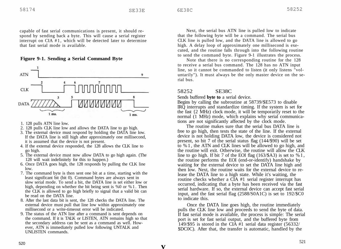
58174 SE33E 6E38C 58252
capable of fast serial communications is present, it should re-spond by sending back a byte. This will cause a serial registerinterrupt on CIA # 1 , which will be detected later to determinethat fast serial mode is available.
1. 128 pulls ATN line low.2. 128 pulls CLK line low and allows the DATA line to go high.3. The external device must respond by holding the DATA line low.
If the DATA line is still high after approximately one millisecond,it is assumed that the device is not present.
4. If the external device responded, the 128 allows the CLK line togo high.
5. The external device must now allow DATA to go high again. (The128 will wait indefinitely for this to happen.)
6. Once DATA goes high, the 128 responds by pulling the CLK linelow.
7. The command byte is then sent one bit at a time, starting with theleast significant bit (bit 0). Command bytes are always sent inslow serial mode. To send a bit, the DATA line is set either low orhigh, depending on whether the bit being sent is %0 or % 1 . Thenthe CLK is allowed to go high briefly to signal that a valid bit canbe read on the DATA line.
8. After the last data bit is sent, the 128 checks the DATA line. Theexternal device must pull that line low within approximately onemillisecond or a write-timeout error will be indicated.
9. The status of the ATN line after a command is sent depends onthe command. If it is TALK or LISTEN, ATN remains high so thatthe secondary address can be sent as a command as well. How-ever, ATN is immediately pulled low following UNTALK andUNLISTEN commands.
520
Next, the serial bus ATN line is pulled low to indicatethat the following byte will be a command. The serial busCLK line is pulled low, and the DATA line is allowed to gohigh. A delay loop of approximately one millisecond is exe-cuted, and the routine falls through into the following routineto send the command byte. Figure 9-1 illustrates the process.
Note that there is no corresponding routine for the 128to receive a serial bus command. The 128 has no ATN inputline, so it cannot be commanded to listen (it only listens "vol-untarily"). It must always be the only master device on the se-rial bus.
58252 SE38CSends buffered byte to a serial device.Begins by calling the subroutine at 58739/$E573 to disableIRQ interrupts and standardize timing. If the system is set forthe fast {2 MHz) clock mode, it will be temporarily reset to thenormal (1 MHz) mode, which explains why serial communica-tions are not significantly affected by the clock mode.
The routine makes sure that the serial bus DATA line isfree to go high, then tests the state of the line. If the externaldevice is not holding DATA low, the device is considered notpresent, so bit 7 of the serial status flag (144/$90) will be setto % 1 , the ATN and CLK lines will be allowed to go high, andthe routine will exit. Otherwise, the routine will allow the CLKline to go high. If bit 7 of the EOI flag (163/$A3) is set to %1 ,the routine performs the EOI (end-or-identify) handshake bywaiting for the external device to set the DATA line high andthen low. Next, the routine waits for the external device to re-lease the DATA line to a high state. While it's waiting, theroutine checks whether a CIA #1 serial register interrupt hasoccurred, indicating that a byte has been received via the fastserial hardware. If so, the external device can accept fast serialinput, and the fast serial flag (2588/S0A1C) is set to 192/$C0to indicate this.
Once the DATA line goes high, the routine immediatelypulls the CLK line low and proceeds to send the byte of data.If fast serial mode is available, the process is simple: The serialport is set for fast serial output, and the buffered byte from149/$95 is stored in the CIA #1 serial data register (56332/$DC0C). After that, the transfer is automatic, handled by the
v521
Figure 9-1. Sending a Serial Command Byte

58252 SE38C
CIA chip hardware. The routine simply waits until a serial reg-ister interrupt indicates that the byte has been completely sent,then resets the port for fast serial input (its default state).
The process for sending a byte in standard (slow) serialmode is more complicated because it is handled in software.Bits are pulled from the buffered byte (149/$95), one at atime, starting with the least significant tit (bit 0). For each bit,the serial bus DATA output line is set either high or low, de-pending on whether the bit to be sent is %0 or % 1 . Then theCLK line is allowed to go high to signal to the external devicethat a valid data bit can be read from the DATA line. After abrief delay, the CLK line is pulled low, and the DATA line is
Figure 9-2. Sending a Serial Data Byte
1. The 128 allows the DATA line to go high. If the external devicedoes not continue to hold the line low, it is assumed that the de-vice is not present.
2. The 128 allows the CLK line to go high.3. The external device must now allow DATA to go high. (The 128
will wait indefinitely for this to happen.)4. Once DATA goes high, the 128 responds by pulling the CLK line
low.5. The data byte is sent one bit at a time using either fast or slow se-
rial mode. To send a bit in slow serial mode {illustrated above),the DATA line is set either low or high, depending on whether thebit being sent is %0 or % 1 . Then the CLK line is allowed to gohigh briefly to signal that a valid bit can be read on the DATAline. Fast serial mode works in a similar manner, except the trans-fer is managed by CIA chip hardware rather than ROM software,and the bits are clocked by pulses on the SRQ line rather than onthe CLK line,
6. After all of the byte is sent, the 128 checks the DATA line. The ex-ternal device must pull that line low within approximately onemillisecond, or a write-timeout error will be indicated.
522
SE38C 58252
allowed to go high again. If the external device holds theDATA line low between bits, a write-timeout occurs (the rou-tine sets bits 0 and 1 in the serial status flag to % 1 , allows theATN and CLK lines to go high, and exits).
After the byte has been sent (in either mode), the routinewaits for the external device to pull the DATA line low. If thisdoes not happen within approximately one millisecond, awrite-timeout occurs, and the routine sets bits 0 and 1 in theserial status flag to % 1 , allows the ATN and CLK lines to gohigh, and exits. Otherwise, the routine at 58783/$E59F is usedto restore interrupts and the clock mode setting, then exitswith the status register carry bit clear. The Y register is unusedduring the routine, and the X register value is preserved. Fig-ure 9-2 illustrates the process of sending a data byte. Figure9-3 illustrates the EOI handshake.
200 \is.
1. As in a normal byte transfer, the external device must hold theDATA line low or it will be assumed that the device is notpresent.
2. The 128 allows the CLK line to go high.3. The external device should then allow the DATA line to go high.
(The 128 will wait indefinitely for this to happen.)4. When the 128 does not respond by pulling the CLK line low
within 200 microseconds, the external device should recognizethat an EOI handshake is being performed and should respond bypulling DATA low again. (The 128 will wait indefinitely for DATAto go low.)
5. The external device should then release DATA high again. The128 will respond by pulling CLK low, and the final byte of the fileis then sent in the usual manner. (See steps 5-6 of Figure 9-2.)
523

58430 6E43E SE43E 58430
58430 8E43E ACPTRReads a byte from a serial device.(This routine has a jump table entry at 65445/$FFA5.)Begins by calling the subroutine at 58739/$E573 to disableIRQ interrupts and standardize timing. If the system is set forthe fast (2 MHz) clock mode, it will be temporarily reset to thenormal (1 MHz) mode, which explains why serial communica-tions are not significantly affected by the clock mode. The rou-tine insures that the serial bus CLK line is free to go high,then tests the state of the line and waits in a loop until it goeshigh. Next, a delay counter is initialized, and the DATA line isallowed to go high. If the external device responds by pullingthe CLK line low before the delay count expires, the routinebegins to process the incoming data bits. Otherwise, it assumesthat the external device is requesting an EOI (end-or-identify)handshake. So the EOI bit (bit 6) of the serial status flag(144/$90) is set to %1 , and the DATA line is pulled low, thenallowed to go high again. The external device must acknowl-edge the EOI handshake by pulling the CLK line low beforeanother delay period expires. If it doesn't, a read-timeout oc-curs, and the routine sets bit 1 in the serial status flag to % 1 ,allows the ATN and CLK lines to go high, and exits.
If a serial register interrupt has occurred on CIA #1, abyte has been received via the fast serial hardware. In thiscase, the byte is retrieved from the serial data register(56332/$DC0C) and stored in 164/$A4; then the fast serialflag (2588/$0AlC) is reset to 192/$C0.
The process for receiving a byte in standard (slow) serialmode is more complicated because it is handled in software.The routine waits for the data line to go high and then for theCLK line to go low. Then, when CLK goes high again, a bit isread from the DATA line and shifted into the working byte(164/$A4). The routine waits until CLK goes low before at-tempting to read the next bit, and the process is repeated foreach of the eight bits of the byte.
After a byte has been received, the DATA line is pulledlow to mark the end of the frame. If the EOI handshake hasbeen performed, the CLK line is allowed to go high. The rou-tine at 58783/$E59F is used to restore interrupts and the clockmode setting. The routine exits with the status register carrybit clear and with the received byte in the accumulator. The Yregister is unused during the routine, and the X register value
524
is preserved. Figure 9-4 illustrates the process of receiving adata byte.
Figure 9-4. Receiving a Serial Data Byte
1. The 128 allows the CLK line to go high and waits for it to go highif the external device is holding it low.
2. Once the CLK line goes high, the 128 allows the DATA line to gohigh.
3. The 128 waits for the external device to respond by pulling theCLK line low. If this hasn't happened after a delay of approxi-mately 260 microseconds, the 128 assumes that an EOI handshakeis requested and briefly pulls the DATA line low. The externaldevice must respond by pulling CLK low before another 260-microsecond delay expires; otherwise, a read-timeout error willoccur,
4. Once the CLK line goes low, the 128 prepares to read data. To re-ceive a bit in slow serial mode (illustrated above), the 128 waitsuntil the CLK line goes high, reads the CIA port bit connected tothe DATA input line, then waits for the CLK line to go low again.Fast serial mode works in a similar manner, except the transfer ismanaged by CIA chip hardware rather than ROM software, andthe bits are clocked by pulses on the SRQ line rather than theCLK line.
5. After the byte is received, the 128 pulls the DATA line low to in-dicate the end of the byte frame.
6. If the EOI handshake is performed, the CLK line is allowed to gohigh after the byte is received.
525

58578 $E4D2 AE515 58645
58578 $E4D2 SECONDSends secondary address after LISTEN.{This routine has a jump table entry at 65427/$FF93.)Stores the secondary address value from the accumulator intothe serial byte buffer at 149/$95, sends the buffered byte as acommand (the ATN line should still be high from the previousLISTEN command), then falls through into the next routine toallow the ATN line to go high again so that following byteswill be seen as data instead of commands.
5 8 5 8 3 $E4D7Allows the serial bus ATN output line to go high.Forces bit 3 of CIA #1 port A to %0. Since that bit is con-nected to the serial bus ATN output line via an inverter, thiswill set the ATN output line to a high state ( + 5 volts).
58592 $E4E0 TKSASends secondary address after TALK.(This routine has a jump table entry at 65430/$FF96.)Stores the secondary address value from the accumulator intothe serial byte buffer at 149/$95, then sends the buffered byteas a command (the ATN line should still be high from theprevious TALK command). If the device is not present, theroutine exits (after allowing the ATN and CLK lines to go highagain). Otherwise, the routine falls through into the next oneto make the 128 the listener and recognize the external deviceas the talker,
58601 $E4E9Performs talk-listen turnaround.Begins by calling the subroutine at 58739/SE573 to disableIRQ interrupts and standardize timing. The DATA line is heldlow, and the ATN line is allowed to go high (signaling theend of the command). The CLK line is then allowed to gohigh. The device which is commanded to talk should respondby pulling CLK low. The routine waits for this to happen, thenjumps to the routine at 58783/$E59F to restore interrupts andthe clock mode. Figure 9-5 illustrates the talk-listenturnaround.
526
Figure 9-5. Talk-Listen Turnaround
1. The 128 holds the DATA line low and allows the ATN line to gohigh.
2. The 128 allows the CLK line to go high.3. The external device must respond by pulling CLK low, (The 128
will wait indefinitely for this to happen.) The external device isnow the talker and the 128 is the listener.
58627 $E503 CIOUTSends a byte to a serial device.(This routine has a jump table entry at 65448/$FFA8.)Tests bit 7 of the serial buffer flag (148/S94). If the bit is %0,indicating that the one-byte serial buffer (149/$95) is empty,the byte in the accumulator is simply stored in the buffer andthe flag bit is set to %1 before exiting. However, if the flag bitis already % 1 , a character is currently waiting in the buffer. Inthis case, the routine at 58252/$E38C is used to send the pre-viously buffered character before the new character is added tothe buffer. Carry will always be clear upon exit, and the bytevalue will still be in the accumulator. The X and Y register val-ues are also preserved. The success of the operation can be de-termined from the value in the serial status flag (144/$90).The purpose of the buffering scheme is to make it possible toperform the EOI (end-or-identify) handshake with the finalcharacter of a file,
58645 $E515 UNTLKSends UNTALK command to a serial device.(This routine has a jump table entry at 65451/$FFAB.)Begins by calling the subroutine at 58739/$E573 to disableIRQ interrupts and standardize timing. The CLK line is pulledlow; then ATN is pulled low as well to indicate that the byte
527

58662 $E526 SE573 58739
will be a command. The accumulator is loaded with the UN-TALK command value, 95/$5F. Then a BIT opcode is used tofall through into the next routine to send the byte as a com-mand. Unlike TALK, which affects only a specified serial de-vice, UNTALK affects all serial devices. However, this shouldn'tcause problems because the 128 serial bus allows only one ac-tive talker at any given time.
58662 8E526 UNLSNSends UNLISTEN command to a serial device.(This routine has a jump table entry at 65454/SFFAE.)Loads the accumulator with the UNLISTEN command value,63/$3F, then clears bit 7 of the serial mode flag (2588/$0AlC)to disable fast serial mode, and sends the byte in the accumu-lator as a command on the serial bus. Afterward, the ATN lineis allowed to go high (signaling the end of the command), and,after a short delay, the CLK and DATA lines are allowed to gohigh as well. Unlike LISTEN, which affects only a specified se-rial device, UNLISTEN affects all serial devices. However, thisshouldn't cause problems because the 128 serial bus normallyhas only one listener at any given time.
58693 $E545Allows serial bus CLK output line to go high.Sets bit 4 of CIA #2 port A to %0. Since the output line forthat port bit is connected to the serial bus CLK output line viaan inverter, this will set the output line to a high state ( + 5volts).
58702 $E54EPulls serial bus CLK output line low.Sets bit 4 of CIA #2 port A to % 1 . Since the output line forthat port bit is connected to the serial bus CLK output line viaan inverter, this will set the output line to a low state (0 volts).
58711 $E557Allows serial bus DATA output line to go high.Sets bit 5 of CIA #2 port A to %0. Since the output line forthat port bit is connected to the serial bus DATA output linevia an inverter, this will set the output line to a high state( + 5 volts).
528 I
58720 $E560Pulls serial bus DATA output line low.Sets bit 5 of CIA #2 port A to % 1 . Since the output line forthat port bit is connected to the serial bus DATA output linevia an inverter, this will set the output line to a low state (0volts).
58729 $E569Reads the serial bus DATA and CLK input lines.Reads the value at port A of CIA #2, then shifts the value ofbit 7, connected to the serial bus DATA input line, into thestatus register carry bit. This will also shift the value of bit 6,connected to the CLK input line, into bit 7. Upon return, theDATA bit can be tested with BCC/BCS or shifted into a work-ing byte, and the CLK bit can be tested with BPL/BMI.
58739 $E573Disables IRQ interrupts and standardizes timing during I/Ooperations.Begins by disabling IRQ interrupts. Next (at 58740/$E574), thecustom mode flag (2618/S0A3A) is checked. If bit 7 of thisflag is set to % 1 , the routine exits without changing the clockmode setting or disabling sprites. The 128 sets this flag to zeroduring the IOINIT routine (part of both the reset andRUN/STOP-RESTORE sequences) and does not normallychange the value. You can set bit 7 of the flag if for some rea-son you want to retain fast clock mode or sprites during anI/O operation. The clock mode storage flag (2615/$0A37) isthen checked. The routine exits if bit 7 of this flag is set to%1 , indicating that a clock mode has already been stored (bits2-7 of $D030 are always %1). Otherwise, the value in theVIOII register at 53296/SD030, which determines the systemclock frequency, is stored in the clock mode flag, and thevalue in the register at 53269/$D015, which determines whichsprites are currently enabled, is stored in 2616/$0A38. Bothregisters are then reset to zero, which disables all sprites andsets the system to normal (1 MHz) clock speed. This is done tostandardize system timing. Tape and serial data transfers relyon software delay loops for critical timing functions, so thesystem must be in a standard mode for the loops to providethe correct delay. If any sprites have previously been enabled,a delay loop is executed before the routine exits.
529

58783 $E59F
58783 $E59FReenables interrupts and restores clock mode after I/Ooperations.Begins by checking the custom mode flag (2618/$0A3A). If bit7 of this flag is set to % 1 , the routine skips ahead to reenableinterrupts and exit. The 128 sets this flag to zero during theIOINIT routine (part of both the reset and RUN/STOP-RESTORE sequences) and does not normally change the value.You can set bit 7 of the flag if for some reason you want theclock mode or sprite enable setting preserved after an I/O op-eration. The clock mode storage flag (2615/$0A37) is thenchecked. If bit 7 of this flag is set to %0, indicating that noclock mode is stored, the routine skips ahead to reenable inter-rupts and exit. Otherwise, the value in 2616/$0A38 is restoredto the VIC-II sprite enable register (53269/$D015), and thevalue in 2615/$0A37 is restored to the clock mode register(53296/$D030). The clock mode flag is then reset to zero. IRQinterrupts are reenabled before exiting.
58812 $E5BCPerforms fast serial turnaround.Waits for a serial register interrupt on CIA #1, indicating thatthe current output byte has been completely sent, then fallsthrough into the next routine to reset the serial port lines forfast serial input. The port is left set up for input so that incom-ing fast serial communications can be detected automatically.
58819 $E5C3 SPINSets serial device for fast serial input.Sets the serial line from CIA #1 for input and halts timer A onCIA #1; then clears bit 3 of the MMU register at 54533/SD505to set the serial port's fast communications hardware for input.
58838 8E5D6 SPOUTSets serial device for fast serial output.Sets bit 3 of the MMU register at 54533/$D505 to set the se-rial port's fast communications hardware for output; thenclears all CIA #1 interrupts. Timer A is loaded with 4/$0004,the timing constant for fast serial output bits. The serial linefor CIA #1 is set for output, and timer A is started. Bytes sub-sequently stored in the serial data register of CIA #1 will besent via the fast serial hardware.
530
SE61B 58907
I
58875 SE5FB SPIN_SPOUTSets serial device for fast serial input or output.Branches to one of the fast serial setup routines, depending onthe setting of the status register carry bit. If carry is clear, theroutine at 58819/$E5C3 is used to set up the port for fast se-rial input. If carry is set, the routine at 58838/$E5D6 is usedto set up the port for fast serial output.
58879 $E5FFprepares next bit for RS-232 transmission.(Called by the NMI handling routine when a timer A interruptoccurs.)If the count of bits remaining to be sent is zero, indicating thatall stop bits for the current byte have been sent, a branch istaken to 58954/$E64A to prepare the next byte for transmis-sion. If bit 7 of the count is set, a branch is taken to 58948/$E644 to prepare to send a stop bit. Otherwise, the next bit tobe sent is pulled from the data byte storage (182/$B6) into thecarry bit, and the parity flag (189/$BD) is updated accordingly.The count of remaining bits is decremented. If the result is zero,a branch is taken to 58907/SE61B to prepare parity or stopbits. Finally, bit 2 of 181/SB5 is set to the bit value to be sent.
58907 $E61BPrepares parity and stop bits.Checks bit 5 of the RS-232 command register (2577/$0All) todetermine whether a parity bit is to be sent. If not (if the bit is%0), the routine skips ahead to determine the number of stopbits. Otherwise, a parity bit is prepared. Bits 6 and 7 of thecommand register determine the parity type. These are possi-ble types:Bits Parity type7 60 0 Odd0 1 Even1 0 Mark1 1 Space
If odd parity is specified, the parity flag (189/$BD) istested. When the flag is nonzero, indicating that an odd num-ber of % 1 bits has already been sent in the current byte, theroutine prepares a parity bit of %0. When the number of %1bits already sent is even, a parity bit of %1 is prepared to
531

5 8 9 4 8 $E644
make the total odd. If even parity is specified, a parity bit of%0 will be prepared when the parity flag indicates that thenumber of %1 bits already sent is even, and a parity bit of %1will be prepared when the number of %1 bits sent is odd sothat the total number of %1 bits sent (including the parity bit)will always be even. Mark and space parity are simpler: In theformer case, the parity bit is always %1; in the latter, it's al-ways %0. (Early versions of the Commodore 64 Kernal incor-rectly computed even and odd parity. All types of parity arehandled properly in the 128 Kernal and in the version of theCommodore 64 Kernal used for 64 mode in the 128.)
Next, the routine prepares for the transmission of eitherone or two stop bits, depending on the setting of bit 7 of theRS-232 control register (2576/$0A10). If one stop bit is speci-fied (if the register bit is %0), the count of bits remaining to besent (180/$B4) is decremented once {to 255/$FF). If two stopbits are sent (if the register bit is %1), the count isdecremented twice (to 254/$FE). The routine ends by branch-ing back into the previous routine to set the prepared parity orstop bit as the next bit to send.
5 8 9 4 8 $E644Prepares to send a stop bit.Increments the count of bits remaining to be sent (180/$B4),then prepares a %1 bit for transmission (stop bits are always%1).
58954 SE64APrepares to transmit next byte.Checks bit 0 of the RS-232 command register (2577/$0All) todetermine which handshaking mode is in use. If x-linehandshaking is specified (if the register bit is %1), the RS-232DSR and CTS lines (pins K and L of the user port) are tested.If the external device is not holding these lines high, the cor-responding bit in the RS-232 status flag (2580/$0A14) is set—bit 6 for DSR missing or bit 4 for CTS missing—then the rou-tine disables timer A interrupts to halt transmission.
For three-line handshaking, or for x-line handshakingwhen DSR and CTS are held high, the parity flag (189/SBD)is cleared and the current bit flag (181/$B5) is set to 0/$00(start bits are always %0). The count of bits to send (180/$B4)
532
$E69D 59037
is loaded from 2581/S0A15. Tf the RS-232 output buffer isempty, the routine disables timer A interrupts and exits. Oth-erwise, the next available byte from the output buffer isloaded into 182/$B6, and the pointer to the head of the buffer(2586/S0A1A) is incremented,
59007 $E67FSets CIA interrupt register and RS-232 activity flag.Sets or clears bits in the interrupt control register for CIA #2,depending on the value in the accumulator. If bit 7 of the ac-cumulator value is %0, the interrupt register bits correspond-ing to the %1 bits in the accumulator value will be cleared. Ifbit 7 is % 1 , the interrupt register bits corresponding to anyother %1 bits in the accumulator value will be set. The RS-232activity flag (2575/$0A0F) is then updated to reflect the newsetting of the interrupt register.
59022 $E68EComputes bit count for the RS-232 operation.Computes a bit count based on the setting of bits 5 and 6 ofthe RS-232 control register (2576/$0A10). The count value,which will be one greater than the number of data bits speci-fied, will be returned in the X register.
Bits6 50 00 11 01 1
Data bits
8765
Bit count
9876
59037 $E69DProcesses received bits.Checks the start bit flag (169/$A9) to determine whether thestart bit for a byte has been read yet. If not, a branch is takento 59092/$E6D4 to see whether this is a start bit. Otherwise,the received bit count (168/SA8) is decremented. If the counthas reached zero, all bits for a byte have been received, so abranch is taken to 59103/$E6DF to process the byte. Other-wise, the parity indicator is toggled, and the received bit in167/$A7 is shifted into the work byte (170/$AA).
533

59058 $E6B2 SE75C 59228
59058 $E6B2Tests for stop bit.Decrements the received bit count and checks whether the re-ceived bit is a %1 (stop bits are always %1). If it is, bit 7 ofthe RS-232 control register (2576/$0A10) is tested. If one stopbit is specified (if the register bit is %0), the routine fallsthrough into the next one to prepare to receive the next byte.If two stop bits have been specified, the routine exits to lookfor another stop bit.
If a stop bit has not been received, the routine branches toset a bit in the serial status flag (2580/$0A14) according to thepreviously received byte (170/SAA): bit 1—the framing errorbit—if the previously received byte is nonzero, or bit 7—thebreak error bit—if the previously received byte is zero (indi-cating that the received data line is being held low).
59074 $E6C2Prepares to receive next byte.Enables FLAG interrupts for CIA #1, then updates the RS-232activity flag (2575/$0A0F) to indicate that FLAG interrupts areactive. The nonzero flag value will also be stored in the startbit flag (169/$A9) to indicate that no start bit has been re-ceived. Timer B interrupts are then disabled, and the activityflag is updated to reflect this. (Timer B interrupts, used to timeincoming bits, are reenabled after the FLAG interrupt occurs,)
59092 SE6D4Tests for start bit.Tests the received bit (in 16 7/$A 7). If it is not %0, it is not astart bit, so a branch is taken to 59074/$E6B2 to look for an-other byte. Otherwise, the zero value is stored in the start bitflag (169/$A9) to indicate that a start bit has been received,and the parity indicator flag (171/$AB) is initialized to 1/S01.
59103 $E6DFStores received character in buffer and checks parity.Checks whether space for an additional character is availablein the input buffer. If not, the routine branches to set the re-ceiver buffer overflow bit (bit 2) in the RS-232 status flag(2580/$0A14) and to prepare for the reception of the nextbyte, (The received character is lost in this case.) Otherwise,
534 1
the received character is padded with %0 bits if it is less thaneight bits long and then stored at the current tail of the inputbuffer. If no parity is used, a branch is taken to 59058/$E6B2to check for a stop bit. Otherwise, the current bit received(167/$A 7) is taken to be a parity bit and is compared againstthe calculated parity for the byte. If the two do not correspondto the specified parity type, the parity error bit (bit 0) of thestatus flag will be set, and the routine will jump to reset forthe reception of the next byte.
59177 SE729Handles CKOUT for RS-232 device.Sets the device number in the accumulator as the current out-put device (154/$9A), then tests bit 0 of the RS-232 commandregister (2577/$0All). If the bit is %0, three-line handshakinghas been specified, so the routine exits at this point. For x-linehandshaking, the routine tests the DSR line (pin L of the userport). If the external device is not holding this line high, abranch is taken to set bit 6 of the RS-232 status flag (2580/$0A14) and exit with the status register carry bit clear. If DSRis high, the state of the RTS line (pin D of the user port) ischecked. If the 128 previously set this line high, the routineexits with carry clear. Otherwise, the routine waits until anycurrent transmission is completed, then waits for the externaldevice to pull the CTS line (pin K of the user port) low. Theroutine then sets the RTS line high to signal that it is ready tosend a byte and waits until an external device sets the CTSline high to acknowledge that it is ready. (If DSR goes lowwhile the routine is waiting, bit 6 of the status flag will beset). The routine then exits with carry clear.
59228 $E75CHandles BSOUT for RS-232 device.(The normal entry point for this routine is 59231/SE75F.)Checks whether the output buffer is currently full. If no spaceis available, the routine loops to enable interrupts for RS-232transmission and waits until space becomes available in thebuffer. The buffer tail pointer (2587/$0AlB) is incremented,and the value in the accumulator is placed at the tail of theoutput buffer. If bit 0 of the RS-232 activity flag (2575/$0A0F)is set to % 1 , timer A interrupts are already enabled, so theroutine exits at this point. Otherwise, timer A is loaded with
535

59285 $E795
the bit timing constant value in 2582-2583/$0A16-$0A17;then timer A interrupts are enabled, and the activity flag is up-dated to reflect this. The routine at 58954/$E64A is called toprepare to transmit the byte; then timer A is started.
59285 $E795Handles CHKIN for RS-232 device.Sets the device number in the accumulator as the current in-put device (153/S99), then tests bit 0 of the RS-232 commandregister (2577/lOAll). If the bit is %0, three-line handshakinghas been specified, so the routine skips ahead to test whetherinterrupts are enabled. For x-Iine handshaking, the routinetests bit 4 of the command register to determine the duplexmode in use. For full duplex (bit 4 is %0), the routine skipsahead to test whether interrupts are available. For half duplex,the RS-232 DSR line (pin L of the user port) is tested. If theexternal device is not holding this line high, a branch is takento set bit 6 of the RS-232 status flag (2580/$0A14) and exitwith the status register carry bit clear. If DSR is high, the stateof the RTS line (pin D of the user port) is checked. If the 128is currently holding this line high, the routine exits with carryclear, then pulls the CTS line (pin K of the user port) low. Theroutine then waits for DTR line to go high, after which FLAGinterrupts are enabled to detect the start bit.
The final step of the routine is to test whether FLAG ortimer B interrupts are enabled. If neither is enabled, FLAG in-terrupts are enabled. The routine exits with carry clear.
59342 $E7CEHandles GETIN for RS-232 device-Checks whether any characters are available in the inputbuffer. If so, bit 3 of the RS-232 status flag (2580/$0A14) iscleared, the buffer head pointer (2585/$0A19) is incremented,and the character from the buffer is returned in the accumu-lator. If no characters are available, bit 3 of the status flag isset to %1 , and the value 0/$00 is returned in the accumulator.The carry bit will be set in this case.
59372 $E7ECDisables RS-232 activity during tape or serial bus operations.Exits immediately if the RS-232 activity flag (2575/$0A0F)contains the value 0/$00, indicating that no RS-232 operations
536
$E805 59397
1
are being used. Otherwise, the routine waits until the trans-mission or reception of the current byte is completed, then dis-ables FLAG interrupts so that no further bytes can be receivedand clears the activity flag so that no more bytes will be sent.The contents of the accumulator are preserved during thisroutine.
59397 SE805Handles NMI interrupts for RS-232.Controls the transmission and reception of data through theRS-232 port. Three CIA #2 interrupt sources are used in RS-232communications. Timer A is used to establish the duration ofbits being transmitted. The FLAG line, which triggers an inter-rupt when it detects a high-to-low transition, is used to initiatethe reception of a byte when an incoming start bit is detected.Timer B is used to time the reception of subsequent bits.
The routine begins by comparing the CIA #2 interruptregister value at the time of the NMI interrupt (in the Y regis-ter when the routine is called by the main NMI handler at65285/$FF05) against the value in the RS-232 activity flag(2575/$0A0F), If bit 0 is set in both, a valid timer A interrupthas occurred to indicate that it is time to send the next bit. So,the bit value (in bit 2 of 181/$B5) is written to bit 2 of CIA #2port A, which is connected to the transmitted data line (pin Mof the user port). RS-232 interrupts are then reenabled bywriting the activity flag contents to the CIA interrupt register(56589/$DD0D). In addition, the routine checks whether bit 1or 4 is set in both the interrupt register value and the activityflag, indicating that a valid FLAG or timer B interrupt occurredconcurrently with a timer A interrupt (RS-232 devices must becapable of simultaneous transmission and reception). If neitherhas occurred, the routine skips ahead to prepare the next bitfor transmission. For timer B interrupts, the subroutine at59512/SE878 is called to read a bit. For FLAG interrupts, thesubroutine at 59561/$EA81 is called to start reception of abyte. The subroutine at 58879/$E5FF is then called to preparethe next bit for transmission. CIA interrupt sources are againenabled before exiting.
If no timer A interrupt occurred, the routine checkswhether bit 1 is set in both the interrupt register value and theactivity flag, indicating that a valid timer B interrupt occurred.If so, the subroutine at 59512/$E878 is called to read a bit.
537

59472 $E850
Otherwise, a test is made of bit 4 in both the interrupt registervalue and the activity flag. If the bit is set in both, a validFLAG interrupt has occurred, so the subroutine at 59561/$E8A9 is called to start reception of a byte. In either case, theactivity flag value is stored in the CIA interrupt register toreenable RS-232 interrupts before exiting.
59472 $E850Table of baud rate timing constants for NTSC systems.The ten two-byte values in this table (in low-byte/high-byteorder) are the CIA timer settings used to transmit and receivebits at the ten standard baud rates when the 128 is operatingwith NTSC clock frequency (1.02273 MHz). This is the for-mula for table values:value = 1.02273E6 / (2 * baud rate) - 100
59492 $E864Table of baud rate timing constants for PAL systems.The ten two-byte values in this table (in low-byte/high-byteorder) are the CIA timer settings used to transmit and receivebits at the ten standard baud rates when the 128 is operatingwith PAL clock frequency (0.985265 MHz). This is the formulafor table values:
value = 0.985265E6 / (2 * baud rate) - 100
59512 $E878Reads a bit from RS-232 device.(Called by the NMI handling routine when a rimer B interruptoccurs.)
Reads the current status of the R5-232 received data line (pinC of the user port) and stores the bit value in 167/$A7. Theinterrupt time for the next bit is calculated and stored in thetimer B latch (56582-56583/$DD06-$DD07); then timer B isrestarted. CIA #2 interrupts are reestablished by storing theRS-232 activity flag (2575/$0A0F) in the interrupt register(56589/$DD0D), and the timer latch is reloaded with $FFFF.The routine ends by jumping to 59037/$E69D to process thereceived bit.
538
SE8D0 59600
59561 $E8A9Initiates reception of RS-232 byte.(Called by the NMI handling routine when a FLAG interruptoccurs.)Begins by copying the bit timing constant value (2578-2579/$0A12-$0A13) into the latch for timer B (56582-56583/$DD06-$DD07) and starting timer B. Then, FLAG interruptsare disabled and timer B interrupts are enabled. The RS-232activity flag (2575/$0A0F) is updated to reflect the change.The latch for timer B is loaded with $FFFF so that the timerwill count continuously after it counts down for the next bit.Finally, the count of bits to be received for the current char-acter is loaded from 2581/$0A15 into the working counter(168/SA8).
59600 SE8D0Reads next header block from tape.Calls the subroutine at 59890/$E9F2 to fill the cassette bufferwith the next block from tape, exiting with the status registercarry bit set if the RUN/STOP key is pressed while the blockis being loaded.
The first byte in the header block, the type identifier, isthen examined. If the identifier value is 5, this is an end-of-tape marker, so the routine branches to exit with carry set (inthis case, the Y register will hold the value 255/$FF). If theidentifier value is something other than 1, 3, or 4, the routineloops back to read another block. If Kernal messages are al-lowed, FOUND is displayed, followed by 16 filename charac-ters from the buffer. (The buffer is filled with space characterswhen the header is written, so the displayed name will bepadded with spaces if it is fewer than 16 characters long.) Adelay loop lasting for two increments of the middle byte of thejiffy clock (161/$A1), about 8-1/2 seconds, is then started. Ifthe space key is pressed during this delay, the routine loopsback to the beginning to read another header. If any other keyin the same column (for example, Commodore or CONTROL)is pressed, the loop is terminated. At the end of the loop, theroutine exits with carry clear. The X register will hold the typeidentifier value for the header.
539

59673 SE919
59673 $E919Writes a header block to tape.Stores the type identifier value from the accumulator in 158/$9E, then checks the address of the cassette buffer, exiting im-mediately if it is less than 512/$0200. Otherwise, the contentsof the starting address pointer (193-194/ $C1-$C2) and end-ing address pointer (174-175/$AE-$AF) for the current opera-tion are stored on the stack, and the cassette buffer is filledwith space characters (32/$20). The type identifier value isplaced in the first byte of the buffer, and the starting addressand ending address values are placed in the next four bytes(each in standard low-byte/high-byte order). The characters, ifany, of the current filename are then copied into the bufferfollowing the filename (the filename can fill the remainder ofthe buffer, up to 187 characters). The buffer starring and end-ing addresses are then set as the operation starting and endingaddresses; the leader flag (171/$AB) is loaded with 105/$69for a long interfile leader; and the subroutine at 59932/$EAlCis called to write the buffer contents to tape as a header. Theoriginal starting and ending address pointer values are thenrestored from the stack. Carry will be clear upon exit unlessthe RUN/STOP key is pressed while the header is beingwritten.
59776 8E980Loads and tests cassette buffer address.Loads the address value in the cassette buffer pointer (178-179/$B2-$B3) into the X and Y registers; then compares the highbyte (in the Y register) with the value 2/$02 to test whetherthe buffer address is greater than 511/$01FR Upon exit, thestatus register carry and Z bits will reflect the result of thecomparison.
59783 $E987Sets buffer address as block addressLoads the address of the cassette buffer into the pointer to thestarting address of the block to be read or written (193-194/$C1-$C2) and the ending address of the buffer (192 bytes be-yond the starting address) into the pointer to the end of theblock (174-175/$AE-$AF).
540
$E9DF 59871
59802 SE99ASearches for a specified header.Calls the routine at 59600/$E8D0 to load the next headerfrom tape into the cassette buffer; exits if carry is set upon re-turn from that routine (indicating that the RUN/STOP key hasbeen pressed or that an end-of-tape header has been read).Characters from the current filename (pointed to by 187-188/$BB-$BC in the bank specified in 199/SC7) are comparedagainst those in the buffer. If all characters match up to theend of the current filename, the names are considered match-ing, and the routine exits with carry clear, regardless of howmany characters may remain untested in the buffer (there'snothing to indicate the length of the name read from tape).However, if a mismatch is found, the routine loops back tosearch for another filename.
59838 $E9BEChecks for cassette buffer filled or emptied.Calls the routine at 59776/$E980 to get the high byte of thecassette buffer address into the X register. The buffer index(166/$A6) is then incremented, loaded into the Y register, andcompared against the value 192/$C0, the maximum count ofcharacters in the buffer. Upon exit, the status register Z andcarry bits will reflect the result of the comparison (both will beset if the end of the buffer is reached),
S9848 $E9C8Requests PLAY button if necessary.Checks whether a tape button is currently pressed; exits withthe status register carry and Z bits set if any buttons are al-ready pressed. Otherwise, if Kernal messages are allowed,PRESS PLAY ON TAPE is displayed. The routine then waitsfor a tape button to be pressed. If the RUN/STOP key ispressed in the meantime, the routine exits with the status reg-ister carry bit set. When a button is pressed, the routine dis-plays OK (if messages are allowed) and exits.
59871 8E9DFChecks tape buttons.Tests the setting of bit 4 of the processor on-chip I/O port(l/$01), connected to the cassette button sense line. The status
541

5 9 8 8 1 SE9E9
register Z bit will be clear if no button is pressed or will be setif any button is detected.
5 9 8 8 1 $E9E9Requests RECORD and PLAY buttons if necessary.Checks whether a tape button is currently pressed; exits withthe status register carry and Z bits set if any buttons are al-ready pressed. Otherwise, if Kernal messages are allowed,PRESS RECORD & PLAY ON TAPE is displayed. The routinethen waits for a tape button to be pressed. If the RUN/STOPkey is pressed in the meantime, the routine exits with the sta-tus register carry bit set. When a button is pressed, OK is dis-played (if messages are allowed) and the routine exits.
59890 $E9F2Reads next header or data block from tape.Clears the tape status flag (144/$90) and operation flag(147/$93) to zero; then sets the starting and ending addressesof the cassette buffer as the starting and ending addresses forthe current operation and falls through into the next routine.
59899 $E9FBReads or verifies a block from tape.Calls the subroutine at 59848/$E9C8 to request that the PLAYbutton be pressed and exits (with carry set) if the RUN/STOPkey is pressed during that subroutine. IRQ interrupts are dis-abled, and a series of variables and counters are initialized.The accumulator is loaded with 144/$90 (the value to enableFLAG interrupts), and the X register is loaded with 14/$0E(the offset for read interrupts), and the routine branches to themain tape I/O routine (59942/SEA26).
59925 $EA15Writes a header or data block to tape.Calls the subroutine at 59783/$E987 to set the buffer ad-dresses as the starting and ending addresses for the operation-then falls through into the next routine to write the bufferblock to tape.
!
$EA26 59942
542.
59928 $EA18Writes a block to tape.Loads the leader flag (171/SAB) with 20/$14 to specify ashort leader between the header and the block; then calls thesubroutine at 59881/$E9E9 to request that the PLAY andRECORD buttons be pressed. (The routine will exit with carryset if the RUN/STOP key is pressed during the subroutine.)IRQ interrupts are disabled and the accumulator is loaded with130/$82 (the value to enable timer B interrupts), and the Xregister is loaded with 8/$08 (the offset to write leader bits).The routine then falls through into the next one to performthe operation.
59942 $EA26Initiates tape I/O operation.Begins by disabling all VIC-II interrupt sources and clearingany pending VIC-II interrupts. The value in the accumulatorupon entry is loaded into the interrupt control register for CIA#1 (56333/$DC0D), and timer B is started. Tape operations de-pend on precise timing, so all other activities that affect systemtiming are disabled: RS-232 interrupts are disabled, the 40-column screen is blanked, and the subroutine at 58740/ $E574is called to switch to standard (1 MHz) clock mode and disablesprites. The current address in the IIRQ vector at 788-789/$0314-$0315 is preserved in 2569-2570/$0A09-$0A0A; thenthe subroutine at 61083/$EE9B is called to load a new valueinto IIRQ, according to the value in the X register. This newIRQ service routine will be responsible for reading or writingdata to tape. The count of blocks to be read or written (190/$BE) is initialized to 2 (blocks are always read or written inpairs). The subroutine at 60762/$ED5A is called to initializevariables; then the tape motor is started, the interlock location(192/$C0) is set to keep it on, and a delay loop is executed toallow the motor to get up to normal speed. IRQ interrupts arethen enabled to begin the reading or writing process.
Since the actual tape operations are performed during IRQinterrupts, the routine must now wait in a loop for the opera-tion to be completed. It continually tests the IRQ storage flag(2570/S0A0A), waiting for the IIRQ vector to be reloaded withthe address stored there, which will happen after the IRQ-driven tape routines are finished. In the meantime, the RUN/STOP key is also tested. If that key is pressed, the operation is
543

60047 8EA8F
halted and the routine exits with carry set. Otherwise, whenthe original IIRQ address is restored at the end of the opera-tion, the vector storage flag will be reset to zero, and the rou-tine will exit with carry clear.
60047 $EA8FChecks for RUN/STOP keypress during tape operations.Calls the Kernal STOP routine [$FFE1] to determine whetherthe RUN/STOP key has been pressed. If it has been, the cas-sette motor is stopped, the default IIRQ vector address is re-stored, the return address of the calling routine is removedfrom the stack, and the IRQ vector storage flag (2570/$0A0A)is cleared.
60065 $EAA1Sets timer A to check for FLAG interrupts.The reception of tape dipole is normally initiated by a FLAGinterrupt from CIA #1, which is triggered by the low-to-hightransition on the cassette read line at the start of a dipole.Timer A of CIA #1 is loaded with a timing value for the typeof dipole being read, and it's used to check whether too muchtime elapses between FLAG interrupts (which should beequally spaced) in an attempt to determine whether any di-poles might have been missed. If no FLAG interrupt occursbefore the timer counts down to zero, the timer will trigger aninterrupt. This prevents the 128 from waiting indefinitely for aFLAG interrupt.
6 0 1 3 9 $EAEBReads or verifies a block of data from tape.{This is a tape IRQ service routine.)
Reads magnetic patterns (known as dipoles) from tape, assem-bles them into bytes, and loads the bytes into memory (orcompares the bytes against memory) until a specified endingaddress is reached. The routine for reading from tape is thelongest and most complex one in the Kernal, and will not bediscussed in detail here. For a thorough description of the pro-cess, refer to COMPUTERS VIC-20 and Commodore 64 Tool Kit:Kernal, by Dan Heeb.
i$ED51 60753
Briefly, the routine reads dipoles from tape and deter-mines whether they represent leaders, word markers, or databytes. The routine does not demand that the dipoles have anabsolutely exact duration, but rather it employs a conceptknown as an adjustable baseline to determine whether the di-pole is within an acceptable range for a particular type. Thismakes it possible to compensate for minor variations in themotor speed of different Datassette units. Because two com-plete copies of the data block are recorded, error correction ispossible. If an error is detected while a byte is being read fromthe first block, the address of the byte which could not be readis recorded in page 1. Up to 31 error addresses can be re-corded in 256-317/$0100-$013D. When the second block isread, the bytes can be corrected if no error is encounteredwhen the byte is read from that block.
When a byte is successfully read from tape, the handlingof the byte depends on the value in the operation flag (147/$93). If the flag value is zero, the byte is stored in the locationpointed to by 172-173/$AC-$AD in the bank specified in198/$C6. If the value is nonzero, the byte is compared againstthe contents of the location pointed to by 172-173/$AC-$ADin the bank specified in 198/$C6 (a verify operation).
Errors which cannot be corrected are recorded in the tapestatus flag (144/S90). If the end of a block is reached beforethe specified ending address (a short-block error), bit 2 of theflag is set to % 1 . If more than 31 errors occur while the firstblock is being read, or if an error recorded during the firstblock cannot be connected during the second block, an unre-coverable-read error occurs, and bit 4 of the flag is set to % 1 .That bit is also set during a verify operation if the byte inmemory doesn't match the corresponding byte in either blockon tape. If the byte read from tape as a checksum doesn'tmatch the calculated checksum for the bytes previously readfrom tape, a checksum error occurs, and bit 5 of the flag is setto % 1 .
60753 $ED51Loads working pointer with starting address.Transfers the starting address of the current block (193-194/$C1-$C2) to the tape working pointer (172-173/$AC-$AD).
544 545

60762 SED5A
60762 $ED5AInitializes tape variables between each byte.Resets the count of bits for the next byte (163/$A3) to 8; thenclears the dipole flag (164/$A4), the word marker half-dipoleflag (168/$A8), the parity work byte (155/$9B), and the wordmarker flag (169/$A9).
60777 $ED69Initiates writing of a tape half-dipole.Reads the bit value for the current half-dipole to be sent (thecurrent value of the rightmost bit in 189/$BD) and loads CIA#1 timer B with the appropriate value: $0060 for a short half-dipole if the bit is %0 or $00B0 for a long half-dipole if the bitis % 1 . The routine then clears the CIA interrupt register, startstimer B, and toggles the cassette write line (bit 3 of the 8502'son-chip I/O port at location l/$01) to begin writing the cur-rent half-dipole. Upon exit, the status register 2 bit will be setif the line is currently low or will be clear if the line is cur-rently high.
60816 6ED90Writes a block of data to tape.(This is a tape IRQ service routine.)Writes bytes of data from memory to tape until the specifiedending address is reached. The system used for representingthe bytes on tape is rather complex. Each bit of a byte is rep-resented by a magnetic pattern called a dipole, which is gener-ated by holding the cassette write line (bit 3 of the 8502's on-chip I/O port at location l/$01) high for a period, then lowfor a different period. The duration of the periods is deter-mined by the value loaded into CIA #1 timer B, which con-trols the amount of time between IRQ interrupts for tape. Theroutine at 60777/$ED69 actually writes each half of the di-pole. A %0 bit is represented by a short half-dipole followedby a long one, while a %1 bit is represented by a long half-dipole followed by a short one. Each byte is preceded by aword marker dipole, which consists of an extra-long wordmarker half-dipole followed by a long half-dipole. Each byte isfollowed by a parity bit dipole. The parity bit will be either%0 or % 1 , as necessary to provide an odd total number of %1bits in the byte and parity bit combined. The routine writestwo complete copies of the data block, separated by a short
546
SEE57 61015
leader. As each byte is written, it is also excIusive-ORed witha checksum work byte. This checksum byte is written to tapefollowing the second copy of the block to provide an addi-tional error check. For a more thorough description of the pro-cess, refer to COMPUTE'S VIC-20 and Commodore 64 Tool Kit:Kernal, by Dan Heeb.
6 0 9 7 4 $EE2EWrites a leader to tape and prepares to write a data block.(This is a tape IRQ service routine.)Writes leader dipoles to tape until the count specified in171/$AB is decremented to zero, about 9.5 seconds for theleader before a header, 1.9 seconds for the leader between aheader and the first data block, or 0.045 seconds between datablocks. The IIRQ vector is then loaded with the address of theroutine to write the data block [$ED90], but if both blockshave been written, the routine branches to 61077/$EE95 to re-store normal IRQs and exit from the operation. Otherwise, thestarting address for the block to be written is loaded into theworking pointer (173-174/$AC-$AD), and a branch is takeninto the block write routine to write the block countdowncharacters. Each block is preceded by a countdown characterpattern—8 7 6 5 4 3 2 1 0—to mark the end of the leader andthe beginning of data. (For the second block of a pair, bit 7 ofthe countdown character codes will be set to %1.)
61015 6EE57Restores IRQ vector and operating modes after tape operation.Reenables the screen (it is normally blanked during tape oper-ations), then checks the custom mode flag (2618/$0A3A). Ifthe flag has bit 7 set, indicating that a special operation modehas been specified, the routine skips ahead to turn off the cas-sette motor and restore the IRQ vector. Otherwise, the VIC-IIchip sprite enable register is reloaded with the value stored in2616/$0A38 at the start of the operation. The clock mode reg-ister is reloaded with its original value from 2615/$0A37; thenthe clock mode storage location is reset to zero to indicate thatno value is stored. The routine to turn off the cassette motor[SEEBO] is called; then raster interrupts are reenabled, and theIIRQ vector (788-789/$0314-$0315) is reloaded with its origi-nal address, stored in 2569-2570/$0AO9-$0A0A at the begin-ning of the operation.
547

61077 $EE95
61077 6EE95Ends tape write interrupts.Calls the subroutine at 61O15/$EE57 to restore the IRQ inter-rupt vector address and system operating modes to their origi-nal values; then exits from the interrupt to return to normalprocessing.
61083 $EE9BLoads IIRQ vector for tape operation.Loads the IIRQ vector (788-789/$0314/$0315) with a valuefrom the table at 61096/$EEA8, depending on the offset speci-fied in the X register:
FunctionWrite a leader to tapeWrite a block to tapeRestore normal IRQ functionsRead a block from tape
Offset Vector address8/$08 60974/$EE2E
10/$0A 60816/$ED9012/$0C 64101/$FA6514/$0E 60139/$EAEB
61104 $EEB0Turns cassette motor off-Sets bit 5 of the processor I/O port (location l/$01) to %1,which has the effect of turning off power to the cassette motor(pins 3 and C of the cassette port).
6 1 1 1 1 $EEB7Tests whether ending address has been reached.
Compares the value in the working pointer for tape and serialoperations (172-173/$AC-$AD) against the ending address in174-175/$AE-$AF. Upon exit, the status register carry and Zbits will reflect the result of the comparison.
6 1 1 2 1 $EEC1Increments the working pointer-
Increments the address in 172-173/$AC-$AD.
61128 $EEC8Handles FLAG interrupts for tape.Insures that the B bit in the status register value on the stackis clear, then jumps to the IRQ interrupt handler [$FF17].
548
$EEEB 61163
61136 $EED0Controls tape motor interlock.Checks bit 4 of the processor I/O port (location l/$01) to de-termine whether any buttons are pressed on the Datassette. Ifno button is pressed (indicated when the bit is %1), the inter-lock byte (192/$C0) is cleared and the tape drive motor isturned off by setting bit 5 of the processor I/O port to % 1 . If abutton is pressed (if bit 4 is %0), the interlock byte is checked.If that byte already contains a nonzero value, the routine exits.Otherwise, the tape motor is turned on by setting bit 5 of theprocessor I/O port to %0.
This routine is part of the normal IRQ sequence, so it'snot possible to control the tape motor by directly changing bit5 of the processor I/O port. If you turn on the motor while nobuttons are pressed, it will be turned off again during the nextIRQ interrupt. If you turn off the motor while a button ispressed, it will be turned on again during the next IRQ inter-rupt (unless the interlock byte contains a nonzero value).
6 1 1 6 3 $EEEB GETINRetrieves a byte from the current input device.(This routine is the normal target of the jump table entry at65508/$FFE4, via the indirect vector at 810/$032A.)Checks whether the current input device (153/$99) is the key-board (device 0) or RS-232 (device 2). If it is neither of these,the routine branches to 61205/SEF15 in the BASIN routine toaccept a byte from the specified device. For keyboard and RS-232, the significant difference between GETIN and BASIN isthat GETIN returns the value 0/$00 if no character is avail-able, whereas BASIN will wait until a valid character becomesavailable.
For keyboard input, the routine checks the number ofcharacters available in the keyboard buffer (208/$D0) and thenumber of characters available from the current programmablekey string (2O9/$D1). If both are zero (no characters avail-able), the routine exits with 0/$00 in the accumulator andcarry clear. However, if characters are available, the screenroutine at 49158/SC006 is used to retrieve the next availablecharacter and return it in the accumulator. Neither the X northe Y register values are preserved in this case.
For RS-232 input, the routine at 59342/SE7CE is used toretrieve a byte from the RS-232 input buffer and return it in
549

61190 SEF06
the accumulator. If the buffer is empty, the accumulator willcontain 0/$00, and bit 3 of the RS-232 status flag (2580/$0A14) will be set to % 1 . For RS-232 input, the X register isunused, and the Y register value is preserved.
61190 $EF06 BASINAccepts a byte from the current input device.(This routine is the normal target of the jump table entry at65487/$FFCF, via the indirect vector at 804/$0324.)If the current input device (153/$99) is the keyboard (device0), the routine sets the current cursor row and column(232/$E8 and 233/$E9) as the starting row and column for in-put (235/SEB and 236/$EC); then it calls the screen editorroutine to retrieve a character from a keyboard input line[$C009], For input from the screen (device 3), the routinestores the device number in the input source flag (214/$D6)and sets the current right window margin (231/$E7) as theending column for input (234/$EA); then it calls the screeneditor routine to retrieve a character from the screen line[$C009], Unfortunately, this is not the proper setup procedurefor screen input, so BASIN from the screen does not work inthe current 128 Kernal. For screen input, the ending row forinput (2608/$0A30) must be specified, and the setting of bit 7of the input source flag must be preserved so that the screeneditor routine will know when the end of the input line isreached. See the entry at 49819/$C29B for details of theproper procedure.
To retrieve a byte from a serial device (device numbergreater than 3), a branch is taken to the routine at 61276/$EF5C. For RS-232 input (device 2), a branch is taken to theroutine at 61287/$EF67. For tape (device 1), this routine fallsthrough into the next routine.
61224 $EF28Accepts a byte from tape.Retrieves a byte from the cassette buffer (2816-3007/$OBO0-$0BBF), then checks the next character in the buffer. Ifthat character is the zero byte marking the end of the file, bit6 of the tape status flag (144/S90) will be set to %1 to indicatethat the end has been reached. If all characters have been re-trieved from the buffer, the next block of data will be read.The retrieved byte will be in the accumulator upon exit and
550
SEF79 61305
the X register contents will be preserved. Carry will be clearunless the RUN/STOP key has been pressed (the accumulatorwill contain 0/$00) or an error is encountered when readingthe data block from tape (the accumulator will contain the er-ror code).
61276 SEF5CAccepts a byte from a serial device.Checks the serial status flag (144/$90) and returns the codefor the RETURN character (13/$0D) if the status is nonzero(indicating error or end of file). Otherwise, the routine jumpsto the Kernal ACPTR routine [$E43E] to retrieve a byte from aserial device.
61287 6EF67Accepts a byte from RS-232.Calls the RS-232 GETIN routine at 61181/SEEFD to retrieve acharacter from the RS-232 input buffer. If the character valueis nonzero, indicating that a valid character has been returned,the routine exits with that value in the accumulator. However,because of a branch to an incorrect address, the routine ne-glects to clear the carry bit, which will be set as a result of thecomparison with zero. Thus, contrary to other versions of theKernal, the carry bit will be set when the character code isvalid. If the value returned is zero, the routine checks bit 6 ofthe RS-232 status flag (2580/$0A14) to determine whether theDSR signal is still present (indicating that the external deviceis still active). If the flag value indicates that the DSR signal ispresent, the routine loops back to see whether a character hasarrived in the input buffer. If DSR is missing, the charactercode for RETURN, 13/$0D, is returned in the accumulatorwith the carry bit clear. In any case, the X register value is un-used and the Y register value is preserved.
61305 $EF79 BSOUTSends a byte to the current output device.(This routine is the normal target of the jump table entry at65490/$FFD2, via the indirect vector at 806/$0326.)If the current output device (154/S9A) is the screen (device 3),the routine jumps to the screen editor routine to display thecharacter in the accumulator [$C00C]. If a serial device is spec-ified (device number greater than 3), the routine jumps to the
551

61332 SEF94
CIOUT routine [$E503] to send the byte in the accumulatorover the serial bus. Otherwise, the value to be sent is stored in158/$9E, and the X and Y register contents are placed on thestack for later restoration. For RS-232 (device 2), a branch istaken to 61367/$EFB7. The branch will also be taken if thekeyboard (device 0) is specified as the output device, but thatshouldn't happen if you use normal Kernal calls to set the de-vice number—CKOUT [$F14C] won't accept the keyboard asan output device. For tape (device 1), this routine falls throughinto the following routine.
6 1 3 3 2 $EF94Sends a byte to tape.
Checks whether the cassette buffer has been filled. If not, thebyte stored in 158/$9E is placed in the next available positionin the buffer. However, if the buffer is currently full, the cur-rent block must be written before the character can be placedin the buffer. The subroutine to write the block to tape[$EA15] is called; then the type identifier value for a datablock (2/$02) is placed in the first byte of the buffer, and thebuffer pointer (166/SA6) is initialized to the next buffer posi-tion, If the RUN/STOP key is pressed while the block is beingwritten, the routine will exit with the status register carry bitset and with the accumulator containing the value 0/$00.
After the character is placed in the buffer, the X and Yregister values will be restored from the stack, and the accu-mulator will be reloaded with the stored byte value so that allregisters have the same value on exit that they did on entry.The carry bit will be clear upon exit.
61367 SEFB7Sends a byte to the RS-232 port.Calls the routine at 59231/$E75F to store the character codefrom the accumulator into the RS-232 output buffer; thenjumps into the preceding routine to restore the accumulatorand X and Y register values from the stack and exits with carryclear.
61373 $EFBD OPENOpens a logical file to a specified device.(This routine is the normal target of the jump table entry at65472/SFFCO, via the indirect vector at 794/$031A.)
552
8EFF6 61430
Checks whether the specified logical file number (184/$B8) isalready used for a currently open file and exits with a Kernalfile-open error if it is (the status register carry bit will be set,and the accumulator will hold the error code, 2/$02).
Next, the routine checks the number of files currentlyopen (152/$98) and exits with a Kernal too-many-files error iften files are already open (the carry bit will be set and the ac-cumulator will hold the error code, l/$01). Otherwise, thenumber of open files is incremented and the logical file num-ber is added to the file number table (866/$0362), The currentsecondary address (185/$B9) is ORed with the value 96/S60and placed in the corresponding position in the secondary ad-dress table (886/$0376). The OR step is significant; some Kernalroutines expect bits 5 and 6 of the secondary address to be set.The current device number (186/$BA) is placed in the cor-responding position in the device number table (876/S036C).
For files opened to the keyboard (device 0) or screen (de-vice 3), the routine exits at this point, since no further setupsteps are required for those devices. For RS-232 files (device2), a branch is taken to the routine at 61504/$F040. For tape(device 1), a branch is taken to the routine at 61430/$EFF6.For a serial device (device number greater than 3), the subrou-tine at 61643/$F0CB is called; then the routine exits withcarry clear (except in the case where the specified device is notpresent).
61430 SEFF6Opens a file for input or output to tape.Checks the cassette buffer address and exits with a Kernal ille-gal-device-number error if it is less than 512/$0200. Thelower four bits of the secondary address are then tested. If allare %0, the file has been opened for reading, so the routinesearches for the specified tape header (or simply for the nextheader if no filename is specified). If the RUN/STOP key ispressed while the routine is searching for the header, the rou-tine will exit with carry set and with the accumulator holdingthe value 0/$00. If an end-of-tape header is read before thedata header is found, the routine exits with a Kernal file-not-found error (the carry bit will be set, and the accumulator willcontain the error code, 4/$04), If a file header is found, theroutine sets the buffer pointer (166/$A6) to 191/$BF {thevalue to indicate that the buffer is empty) so that the first
553

6 1 5 0 4 SF040
block of data will be read when BASIN is called for the firsttime; then it exits with carry clear.
This routine does have a flaw: It neglects to checkwhether the loaded header block has a type identifier of 4 (thetype identifier for data file headers). Thus, if a program file(type identifier of 1 or 3) is found with the specified name, orbefore the next data header if no name is specified, it will beopened. However, tape program files cannot be read or writ-ten, only saved or loaded, so it does no good to open them forreading. When a program file is opened, a long block error oc-curs after you try to read the first block.
If any of bits 0-3 of the secondary address are % 1 , a datafile will be opened for writing. The subroutine to request thatthe PLAY and RECORD buttons be pressed is called. If theRUN/STOP key is pressed during that subroutine, the routinewill exit with carry set and with the accumulator containing0/$00. The subroutine at 59673/$E919 is then called to writea data header for the file (type identifier of 4). After theheader is written, the data block type identifier value (2/$02)is placed in the first position of the cassette buffer; then thebuffer pointer is initialized to the next position, and the rou-tine exits with carry clear.
61504 $F040Opens a file for RS-232 communications.Calls the subroutine at 61616/$F0B0 to initialize the CIA #2port lines to the user port; then clears the RS-232 status flag(2580/$OA14) and retrieves up to four characters from the cur-rent filename (if more are specified, those after the first fourare ignored). The first character, if present, is placed in the RS-232 control register (2576/$0A10), the second into the com-mand register (2577/$0All), and the last two into the baudrate timing constant (2578-2579/$0A12-$0A13). The numberof bits to be sent or received is calculated and stored in2581/$0A15. The lower four bits of the control register valueare checked to determine the baud rate to use. If the bits areall %0, a custom rate is indicated, so the following step toload a value from the tables is skipped. Otherwise, the valuefrom bits 0-3 is used as an index into one of the baud ratetiming constant tables, depending on the video system in use(59470/$E84E for NTSC or 59490/$E862 for PAL), and thespecified table entry is loaded into 2578-2579/$0A12-$0A13.
554
SFOBO 6 1 6 1 6
No error checking is done, so if you specify a value greaterthan 10 (%1010) in those bits, you'll wind up with an invalidtiming constant and won't be able to send or receive data.Also, for higher baud rates, the time between interrupts is soshort that the system may not have time to process receivedbytes. In general, stick to rates of 1200 baud or lower.
The rate factor value in 2578-2579/$0A12-$0A13 is thenconverted into a bit timing constant, the number of CIA timercounts for the bit duration, and the result is stored in2582-2583/$0A16-$0A17. The formula is bit time equals ratefactor times 2 plus 200.
Next, the routine checks the handshaking setting specifiedby bit 0 of the command register. For x-line handshaking, theroutine checks the CIA port bit connected to the DSR line (pinL of the user port). If the external RS-232 device is not holdingthis line high, bit 6 of the RS-232 status flag will be set. How-ever, there's a bug here: If the line is high, indicating that theexternal device is present, the routine will proceed with carryset, which is normally used to indicate a problem. (Carry clearupon return from OPEN is supposed to mean that the file hasbeen opened successfully.)
If you're calling OPEN from machine language, you canjust remember that a set carry can be ignored when x-linehandshaking is in use. However, BASIC still thinks a problemhas occurred and will give a DEVICE NOT PRESENT errorwhen the device is present. The converse side of the problemis that carry will be clear when DSR is low, so BASIC willthink everything is okay when the device is absent.
The final step is to set the input buffer tail pointer(2585/S0A19) equal to the head pointer (2584/$0A18), andthe output buffer head pointer (2586/S0A1A) equal to the tailpointer (2587/$0AlB). This effectively makes both buffers ini-tially empty.
6 1 6 1 6 $F0B0Sets up CIA #2 ports for RS-232 communications.Disables all interrupt sources from CIA #2; then makes theuser port lines connected to bits 0 and 3-7 of port B inputs,while making the lines for bits 1-2 outputs and setting themhigh (+5 volts). The line for bit 2 of port A (initialized to anoutput line during IOINIT) is set high. This is the transmitteddata line, which is normally held high when no data is being
555

6 1 6 4 3 $FOCB
sent. For information on the usage of the other lines, refer tothe discussion of CIA #2 in Chapter 8. Finally, the RS-232 ac-tivity flag (2575/S0A0F) is cleared to indicate that no CIA #2interrupts are enabled.
61643 $FOCBOpens a file for serial bus communications.Checks the current secondary address (185/$B9) and exits im-mediately (with the status register carry bit clear) if the sec-ondary address value has bit 7 set (if the value is greater than127). The routine also exits without performing any other ac-tions if the length of the name specified for the file beingopened (183/SB7) is zero. Otherwise, the serial status flag(144/$90) is cleared to zero, and the specified device (186/$BA) is commanded to listen. If the serial status flag indicatesthat the device has not responded, the return address of thecalling routine will be discarded and the routine will exit witha Kernal device-not-present error (the carry bit will be set andthe accumulator will contain the error code, 5/$05). If the de-vice has responded, the secondary address is sent as a com-mand using the SECOND routine [$E4D2]. (The upper fourbits of the secondary address are masked to %0000, so onlythe lower four bits are significant.) Again, if the device doesnot respond, the routine exits OPEN with a Kernal device-not-present error. If a filename has been specified, the charactersof the name are sent to the serial device. (Since the ATN lineis allowed to go high after the secondary address is sent, thefilename characters are not seen as commands.) The routineends by commanding the device to unlisten.
61702 $F106 CHKINSets the current input file for GETIN and BASIN.(This routine is the normal target of the jump table entry at65478/$FFC6, via the indirect vector at 798/$031E.)
Checks whether a file with the logical file number specified inthe X register is currently open by verifying that a matchingentry exists in the logical file table at 866-875/$0362-$036B.If no match is found, the routine exits with a Kernal file-not-open error (the status register carry bit will be set and the ac-cumulator will hold the error code, 3/$03). If an entry for thefile is found in the table, the file number is loaded into184/SB8, and the corresponding device number and secondary
556
$F14C 61772
address values are loaded into 186/SBA and 185/SB9, respec-tively. If the device number is 0 (keyboard) or 3 (screen), theroutine skips ahead to set this as the input device number andexit, since that's all that's necessary for input from thosesources. For device numbers greater than 3 (serial devices), abranch is taken to the routine at 61735/$F127. For device 2(RS-232), a jump is taken to the routine at 59285/$E795 toprepare for RS-232 input. For device 1 (tape), the secondaryaddress is tested. If it is not 96/$60 (0/$00 before the OR inthe OPEN routine), the file has been opened for writing, sothe routine exits with a Kernal not-input-file error (the statusregister carry bit will be set and the accumulator will hold theerror code, 6/$06). Otherwise, the device number is set as thecurrent input device (153/$99), and the routine exits withcarry clear.
61735 $F127Prepares a serial device file for input.Sends a TALK command to the serial device specified in theaccumulator, then tests the serial status flag (144/$90) to seewhether the device has responded. If the flag indicates thatthe device is not present, the routine exits with a Kernal de-vice-not-present error (the status register carry bit will be setand the accumulator will contain the error code, 5/$05). If thedevice has responded, the routine checks the value of the sec-ondary address (185/$B9). If bit 7 of the value is %1 (if thesecondary address is 128 or greater), no secondary address issent—the routine simply performs the talk-listen turnaround.Otherwise, the TKSA routine [$E4E0] is called to send the sec-ondary address as a command on the serial bus and performthe talk-listen turnaround. If the device responds again, theroutine sets the device number as the current output device(154/$9A) and exits with carry clear. If the device does not re-spond, the routine exits with a Kernal device-not-present error.
61772 $F14C CKOUTSets the current output file for BSOUT.(This routine is the normal target of the jump table entry at65481/$FFC9, via the indirect vector at 800/$0320.)Checks whether a file with the logical file number specified inthe X register is currently open by verifying that a matchingentry exists in the logical file table at 866-875/$0362-$036B.
557

61805 $F16D
If no match is found, the routine exits with a Kernal file-not-open error (the status register carry bit will be set and the ac-cumulator will hold the error code, 3/$03). If an entry for thefile is found in the table, the file number is loaded into 184/$B8, and the corresponding device number and secondary ad-dress values are loaded into 186/$BA and 185/$B9, respec-tively. If the device number is 0, the routine exits with aKernal not-output-file error (the status register carry bit will beset and the accumulator will hold the error code, 7/$07), sinceit's not possible to send output to the keyboard. If the devicenumber is 3, the routine skips ahead to set this as the outputdevice number and exit, since that's all that's necessary toroute output to the screen. For device numbers greater than 3(serial devices), a branch is taken to the routine at 61805/$F16D. For device 2 (RS-232), a jump is taken to the routineat 59177/$E729 to prepare for RS-232 output. For device 1(tape), the secondary address is tested. If it is 96/$60 (0/$00before the OR in the OPEN routine), the file has been openedfor reading, so the routine exits with a Kernal not-output-fileerror. Otherwise, the device number is set as the current out-put device (1154/$9A), and the routine exits with carry clear.
61805 8F16DPrepares a serial device file for output.Sends a LISTEN command to the device specified in the accu-mulator, then tests the serial status flag (144/$90) to seewhether the device has responded. If the flag indicates thatthe device is not present, the routine exits with a Kernal de-vice-not-present error (the status register carry bit will be setand the accumulator will contain the error code, 5/$05), If thedevice has responded, the routine checks the value of the sec-ondary address (185/$B9). If bit 7 of the value is %1 (if thesecondary address is 128 or greater), no secondary address issent—the routine simply allows the serial bus ATN line to gohigh. Otherwise, the SECOND routine [$E4D2] is called tosend the secondary address as a command on the serial bus. Ifthe device responds again, the routine sets the device numberas the current output device (154/$9A) and exits with carryclear. If the device does not respond, the routine exits with aKernal device-not-present error.
558
SF1A9 61865
61832 $F188 CLOSECloses a specified logical file.(This routine is the normal target of the jump table entry at65475/$FFC3, via the indirect vector at 796/$031C.)Shifts the value of the status register carry bit upon entry intobit 7 of 146/$92; then checks whether a file with the logicalfile number specified in the accumulator is currently open. Ifnot, the routine simply exits with carry clear. If an entry forthe file is found in the file number table, the file number isloaded into 184/$B8, and the corresponding device numberand secondary address values are loaded into 186/$BA and185/$B9, respectively. The file's position in the tables isplaced on the stack for later retrieval. The routine then checkswhether the file is open to the keyboard (device 0) or screen(device 3). In either of these cases, simply removing the tableentries for the file is sufficient to close the file, so a branch istaken to the routine at 61924/$F1E4. For device numbersgreater than 3 (serial devices), a branch is taken to the routineat 619O3/$F1CF. For device 1 (tape), a branch is taken to theroutine at 61865/$F1A9. For device 2 (RS-232), the table en-tries for the file are deleted, then a jump is taken to the rou-tine at 61616/$F0B0 to reinitialize the CIA ports and disablethe interrupts that drive RS-232 communications.
61865 $F1A9Closes a tape file.Checks the secondary address for the file (185/$B9). If it is 0,indicating that the file has been opened for reading, all that isrequired is to delete the table entries for the file, so a branch istaken to 61924/$F1E4. If the file has been opened for writing,the routine adds a zero following the last data byte in thebuffer (which contains the final block of data for the file), thenwrites the final block to tape. If the RUN/STOP key is pressedwhile the last block is being written, the routine will exit withstatus register carry bit set and with the accumulator holding0/$00. If bit 1 of the secondary address is set to % 1 , then anend-of-tape header will be written following the final datablock. The routine then jumps to 61924/$F1E4 to remove thetable entries for the file.
559

61903 SF1CF SF23D 62013
61903 SF1CFCloses a file on a serial device.Checks the preserved status of the cany bit when the CLOSEroutine is entered. If carry is set, and if the device number(186/$BA) is 8 or greater, and if the secondary address for thefile is 15 (indicating that the file has been opened as a com-mand channel to the drive), a branch is taken to 61924/$F1E4to simply remove the file entries rather than actually closingthe file. This provides a solution to a problem in previous ver-sions of the Kernal. Closing the command channel to a drivealso closes all other open files on the drive, possibly an un-wanted side effect. By calling CLOSE with carry set, this cannow be avoided.
If carry is clear when CLOSE is called, the normal closingsteps are performed: The subroutine at 62878/$F59E is calledto close the file on the serial device; then the routine fallsthrough into the next one to remove the table entries for thefile.
61924 SF1E4Removes an entry from the logical file tables.Retrieves the offset to the file's position in the logical filenumber, device number, and secondary address tables fromthe stack and decrements the number of open files (152/$98).Next, the routine checks whether the file to be deleted is thelast entry in the tables. If so, decrementing the number ofopen files is sufficient to effectively remove the file's table en-tries; and the routine exits at this point. Otherwise, the currentlast entry in the table is copied to the specified file's position,overwriting the entries for the file to be deleted. Carry will al-ways be clear upon exit.
61954 $F202Checks whether a file is already open.Clears the serial status flag (144/$90), then searches the logi-cal file number table (866-875/$0362-$036B) for an entrywith the same number as the value specified in the X register.If no match is found, or if no files are open, the routine exitswith the status register N bit set (test with BMI). If a file usingthe specified number is already open, the status register Z bitwill be set (test with BEQ).
560
61970 $F212Load parameters for a logical file.Loads the current logical file number (184/$B8), current de-vice number (186/SBA), and secondary address (185/$B9)with the values for a specified open file from the tables at866-895/$0362-$037E The routine should be called with theX register containing the offset (0-9) into the tables for thefile's entry.
61986 8F222 CLALLClears file table entries,(This routine is the normal target of the jump table entry at65511/$FFE7, via the indirect vector at 812/$032C.)Resets the number of open files (152/$98) to zero, then fallsthrough into the next routine to reestablish default I/O channels.Note that this routine doesn't actually close any files that maybe open to external devices. Unclosed tape or disk files maycause problems and should be avoided. See the CLOSE ALLentry at 62013/$F23D for a routine that properly closes allfiles opened to a specified serial device.
61990 $F226 CLRCHResets default I/O channels.(This routine is the normal target of the jump table entry at65484/$FFCC, via the indirect vectoT at 802/$0322.)Sends an UNLISTEN command over the serial bus if the cur-rent output device number (154/S9A) is greater than 3, and anUNTALK command if the current input device number (153/$99) is greater than 3. The channels are then reset to the de-fault devices: 3 (screen) for output and 0 (keyboard) for input.
62013 $F23D CLOSE_ALLCloses all open files for a specified serial device.(This routine has a jump table entry at 65354/$FF4A.)Stores the value in the accumulator as the current device num-ber (186/$BA). If the specified device number is the currentinput or output device, the input or output channel is reset tothe default device (keyboard or screen). Next, the routinesearches the device number table at 876-885/$036C-$0375for files that might be open to the specified device. Any thatare found are closed by using the Kemal CLOSE routine65475/$FFC3.
561

62053 8F265
62053 $F265 LOADLoads or verifies a program file from disk or tape.(This routine has a jump table entry at 65493/SFFD5.)Stores the address value from the X and Y registers into thepointer to the starting address for the load (195-196/$C3-$C4), then takes an indirect jump through the ILOADvector (816/$0330). The vector normally points back to the lo-cation immediately following the jump, but you can modifythe action of the LOAD routine by redirecting this vector to aroutine of your own. See the ILOAD entry for details.
The operation type value in the accumulator is stored inthe load/verify flag'(147/$93), and the tape/serial status flag(144/$90) is cleared. The device number (186/$BA) is thentested. If it's 4 or greater, a branch is taken to the routine at62075/$F27B to attempt a load from the specified serial de-vice. Otherwise, a jump is taken to the routine at 62246/$F326 to attempt a load from tape.
62075 $F27BLoads or verifies a file from a serial device.Begins by clearing bits 6 and 0 of the fast serial flag($2588/$0AlC). Bit 6 is cleared so that the routine which at-tempts fast serial output will have to verify for itself that fastcommunications are available; there is no apparent reason forclearing bit 0. The current secondary address (185/$B9) isplaced in temporary storage (158/$9E). If the length of thecurrent filename (183/$B7) is zero, the routine exits with theKernal missing-filename error (the status register carry bit willbe set and the accumulator will hold the error code, 8/$08).Otherwise, the length value is placed in temporary storage(159/$9F), and (if Kernal control messages are allowed)SEARCHING FOR, followed by the filename, is displayed.The subroutine at 62369/$F3Al is called to attempt a fast se-rial load or verify of the specified file. If carry is clear upon re-turn (indicating that a fast load or verify has been performed),the routine exits with carry clear and with the X and Y regis-ters holding the ending address for the data. Otherwise, theroutine proceeds with the standard serial load or verify.
The filename length is restored from temporary storage,and the current secondary address is set to 96/$60—cor-responding to a secondary address of zero, the value for read-ing a file. The serial OPEN routine [$F0CB] is called to send
562
SF326 6 2 2 4 6
the filename to the specified device; then the device is com-manded to talk and is sent the secondary address. The firsttwo bytes, which, for a program (PRG) file, contain the start-ing address, are loaded into the working pointer (174-175/$AE-$AF). If the original secondary address value in 158/$9Eis 0/$00, indicating that a relocating load has been specified,the starting address in the pointer is replaced with the one in195-196/$C3-$C4. If Kernal messages are allowed, LOAD-ING or VERIFYING is displayed.
The main reading step consists of clearing the readtimeout bit (bit 1) of the serial status flag, checking for aRUN/STOP keypress, calling ACPTR [$E43E] to read a bytefrom the program file, and testing whether the read timeoutbit has been set during the read. If it has been set, the routineloops back to try to read the byte again. If RUN/STOP ispressed, the routine goes to 62901/$F5B5 to halt theoperation.
For a verify operation (nonzero value in 147/$93), thebyte read from disk is compared to the one at the addresspointed to by 174-175/$AE-$AF in the bank specified in198/$C6. If the bytes do not match, the verify error bit (bit 4)in the serial status flag is set to % 1 . For a load operation (0 in147/$93), the byte read from disk is stored at the addresspointed to by 174-175/$AE-$AF in the bank specified in198/$C6. In either case, the address in the pointer is then in-cremented and compared against the value 65280/$FF00. If itreaches this value, a Kernal out-of-memory error occurs (theroutine exits with carry set and with the accumulator holdingthe error code, 16/$10). If the EOI bit in the serial status flag(bit 6) is not % 1 , the routine loops back to read another byte.When EOI is set, indicating that the end of the file has beenreached, the routine sends an UNTALK command, closes thefile, loads the address from 174-175/$AE-$AF (which willpoint to the location immediately following the last byteloaded) into the X and Y registers, then exits with carry clear.
62246 $F326Loads or verifies a program file from tape.Exits with the Kernal illegal-device-number error if the devicenumber in the accumulator is not 1/S01, or if the cassettebuffer address is less than $0200. (The status register carry bitwill be set and the accumulator will hold the error code,
563

62369 8F3A1
9/$09.) Otherwise, a request for the PLAY button will beprinted if no buttons are currently pressed, and if Kernal mes-sages are allowed. If the RUN/STOP key is pressed whilewaiting for a button press (or at any other time during theroutine), the routine will exit with carry set and with 0/$00 inthe accumulator. If Kernal messages are allowed, SEARCHINGis displayed; if a nonzero filename length is specified, that willbe followed by FOR and the filename. If a filename is sup-plied, the routine looks for a specified header block [$E99A],Otherwise, it merely loads the next header block [$E8D0], Ineither case, if an end-of-tape header (type identifier of 5) isencountered, the routine exits with a Kernal hie-not-found er-ror (the carry bit will be set and the accumulator will hold theerror code, 4/$04). The routine also exits with carry set if bit 4of the tape status flag (144/$90) is %1 after the header isloaded, indicating that a read error has occurred. If the typeidentifier byte for the header is not 1 or 3, this is not a pro-gram file, so the routine loops back to read another header.
If the type identifier is 3, indicating that this is anonrelocatable program file, or if the secondary address(185/$B9) is nonzero, the current starting address pointervalue in 195-196/$C3-$C4 is replaced with the one specifiedin the two header bytes following the type identifier. Next, theending address for the file is calculated and stored in174-175/$AE-$AF. If the ending address value is greater than65279/$FEFF, the routine exits with a Kernal out-of-memoryerror (the carry bit will be set and the accumulator will holdthe error code, 16/$10). The starting address is transferred toa working pointer (193-194/$C1-$C2) and, if Kernal mes-sages are allowed, LOADING or VERIFYING is displayed. Thesubroutine at 59899/$E9FB is used to read the program datafrom tape into the specified area of memory (carry should beclear upon return if the load is successful). Finally, the endingaddress is loaded into the X and Y registers before exiting.
62369 $F3A1Attempts to set up fast serial load or verify.Checks the first character of the filename to be loaded and ex-its immediately if it's $, indicating that a disk directory ratherthan a program is to be loaded. Otherwise, the routine opensa command file (secondary address of 15) to the specified se-rial device. If the file is not opened successfully, the routine
564
8F3EA 62442
exits with the Kernal device-not-present error (tVie status regis-ter carry bit will be set and the accumulator will hold the errorcode, 5/$05). If the command channel has been opened, theburst mode load command—UO, followed by the value 31 /$1F to specify a program file, followed by the codes for thecharacters of the filename—is sent to the drive. The CLRCHroutine [$FFCC] is called to reset the default I/O channels. Bit7 of the fast serial flag at 2588/$0AlC is then tested. If the se-rial device is capable of fast serial communications, the bit willhave been set to %1 by the BSOUT routine calls used to sendcharacters to the device. In this case, the routine branches to62442/SF3EA to perform the operation using the very highspeed burst mode. If fast serial communications are not avail-able, the command channel file is closed, and the routine re-turns with carry set, indicating that a standard (slow) load orverify must be performed.
62442 $F3EALoads or verifies a file using fast serial burst mode.Performs a high-speed load or verify of the file specified in thepreceding routine. Burst mode loads are quite different fromstandard loads. In burst mode, data is sent a sector (254 bytes)at a time. A status byte is sent before the data bytes for eachsector. The serial bus CLK line must be toggled between bytesto acknowledge receipt of the byte.
The routine begins by restoring the filename length(183/$B7) from temporary storage (159/$9F), then disablingIRQ interrupts, allowing the serial bus CLK line to go highand setting the serial port for fast serial input. The status bytefor the first sector is read. If the status value is 2/$02, thespecified file has not been found, so the command channel tothe drive is closed and the routine exits with a Kernal file-not-found error (the status register carry bit will be set and the ac-cumulator will hold the error code, 4/$04). If the status byte is31/$1F, the file is only one block long. The LOADING orVERIFYING message is then displayed (if Kernal control mes-sages are allowed), and the first two data bytes from the firstsector are then read and stored in the starting address pointer(174-175/$AE-$AF), If the stored secondary address (158/$9E) is zero, a relocating load has been specified, so thepointer is reloaded with the value from 195-196/$C3-$C4.The starting address is then transferred to the working pointer(172-173/$AC-$AD).
565

62616 $ F 4 9 8
Before each sector is read, the RUN/STOP key is tested.If that key has been pressed, a branch is taken to the routineat 62630/$F4A6 to halt the operation. Otherwise, the count ofdata bytes in the sector (165/$A5) is initialized—252 bytes fora full first sector, 254 bytes in following full sectors, and avariable number of bytes in the last sector—and the subrou-tine at 62661/$F4C5 is called to load or verify the data bytes.After each sector is loaded or verified, the status byte for thenext sector is read. If the status value is 0 or 1, the routineloops to read the next sector. If it is 31/$IF, the next block isthe last one for the file, so an additional byte is read from thedevice. This value will be the number of bytes in the final sec-tor. If the status value is 2 or greater (but not 31), an error hasoccurred, so a branch is taken to the routine at 62616/$F498to handle the error.
After all bytes for the file have been read, the routine al-lows the CLK line to go high, reenables IRQ interrupts, andcloses the command channel file. (The status register carry bitis set before CLOSE [$FFCC] is called so that the special com-mand file close is performed.) The status register carry bit willbe clear upon exit for a successful load. Bit 4 of the serial sta-tus flag (144/$90) will reflect the success of a verify operation.
62616 $F498Handles read error during burst mode load/verify.Sets bit 1 of the serial status flag (144/$90) to %1 to indicate aread timeout. Then it discards the return address of the callingroutine and exits with the status register carry bit set and theaccumulator holding the value 41/$29, the code for BASIC'SFILE READ error message.
62630 SF4A6Stops burst mode load/verify if RUN/STOP key pressed.Closes the file, then changes the current secondary address tozero, discards the return address of the calling routine, and ex-its with the status register carry bit set and the accumulatorholding the value 0/$00.
566
SF503 62723
62642 $F4B2Aborts burst mode load/verify if maximum address exceeded.Closes the file, then discards the return address of the callingroutine and exits with the Kernal out-of-memory error (uponexit, the status register carry bit will be set and the accumu-lator will hold the error code, 16/$10).
62650 SF4BAReads a byte using fast serial hardware.Waits for a serial register interrupt to occur on CIA # 1 (indi-cating that a byte has been received via the fast serial hard-ware), then retrieves the byte from the serial data register andreturns it in the accumulator.
62661 $F4C5Loads or verifies a block of data using burst mode.Waits for a serial register interrupt to occur on CIA #1 (indi-cating that a byte has been received via the fast serial hard-ware); then retrieves the byte from the serial data register andtoggles the CLK line to acknowledge reception of the byte. Ifthe operation flag (147/S93) contains a nonzero value, indicat-ing verify, the byte read from the serial bus is compared withthe one pointed to by 174-175/$AE-$AF in the bank speci-fied in 198/$C6. If the bytes do not match, the verify error bit(bit 4) of the serial status flag (144/$90) is set to % 1 . For aload operation, the byte read from the bus is stored at the ad-dress pointed to by 174-175/$AE-$AF in the bank specifiedin 198/$C6. The address value in the pointer is then incre-mented; if it exceeds 65279/$FEFF, the routine will exit withthe status register carry bit set. The count of bytes to be readfrom this sector (165/$A5) is decremented. If bytes remain tobe read, the routine is repeated. Otherwise, it exits with carryclear and with the accumulator holding the high byte of thenext load address.
62723 $F503Toggles state of serial bus CLK line.Reverses the value of bit 4 of CIA #2 port A. Since the line forthis bit is connected to the serial bus CLK output line, this willreverse the state of the line. This is the handshake for burstmode loads from disk.
567

62735 $F50F
62735 $F50FDisplays SEARCHING FOR message.Checks the Kernal message flag (157/$9D), exiting immedi-ately if messages are not allowed. The message SEARCHINGis displayed; then the current filename length (183/$B7) istested. If it's nonzero, the message FOR and the characters ofthe filename are displayed following SEARCHING.
6 2 7 7 1 $ F 5 3 3Displays LOADING or VERIFYING message.Loads the accumulator with the offset for either the LOAD-ING or VERIFYING message, depending on whether the valuein the operation flag (147/S93) is zero or nonzero. The routineat 63262/$F7lE is then called to display the message (ifKernal messages are allowed).
62782 $F53E SAVESaves a block of memory to tape or disk.(This routine has a jump table entry at 65496/$FFD8.)Stores the address value from the X and Y registers into thepointer to the ending address for the save (174-175/$AE-$AF),and stores the address from the two-byte zero-page pointerspecified in the accumulator into the pointer to the starting ad-dress for the save (193-194/$C1-$C2). The routine then takesan indirect jump through the ISAVE vector at 818/$0332.That vector normally points back to the location immediatelyfollowing the indirect jump, but you can modify the actions ofthe SAVE routine by redirecting the vector to your own rou-tine. See the ISAVE entry in Chapter 2 for details.
The device number (186/$BA) is then tested. If it's 1(tape), a branch is taken to the routine at 62920/$F5C8. If it's4 or greater (serial device), a branch is taken to the routine at62817/$F561. Otherwise, the routine exits with the Kernalillegal-device-number error (the status register carry bit will beset and the accumulator will hold the error code, 9/$09).
62817 SF561Saves a block of memory to a serial device.Begins by checking the filename length (183/$B7). If thelength value is zero, the routine exits with the Kernal missing-filename error (the status register carry bit will be set and theaccumulator will contain the error code, 8/$08). The second-
568
SF5B5 6 2 9 0 1
ary address is set to 97/$61, the value to open a program filefor writing; then a file is opened using the current filename(pointed to by 187-188/$BB-$BC). A LISTEN command issent to the current device (186/$BA) along with the secondaryaddress. The low and high bytes of the starting address for thesave are then written as the first two bytes of the file.
The subroutine at 63436/$F7CC is used to retrieve a bytefrom the specified memory area, and the subroutine at 58629/$E503 is used to write the byte to the file (using fast serialmode if it is available). After each byte, the routine checkswhether the RUN/STOP key has been pressed. If it has beenpressed, a branch is taken to the routine at 62901/$F5B5 toabort the SAVE. Otherwise, the address pointer is incremented,and the process repeats until all bytes have been written.(Before this routine is called, the starting address must beloaded into 193-194/$C1-$C2 and the ending address plus 1into 174-175/$AE-$AF.) When all bytes have been written,an UNLISTEN command is sent to the serial device; then theroutine falls through into the following one to close the file.
When fast serial communications are available, files areloaded by sectors (254-byte chunks of data) using a specialfeature of the 1571 drive known as burst mode. However, fastmode SAVEs are still done byte by byte. This is the reasonmore time is required to save a file using fast serial mode thanto load a file of the same length,
62878 $F59ECloses a file on a serial device.Exits immediately if the secondary address is greater than127/$7F (if bit 7 of 185/$B9 is %1). Otherwise, a LISTENcommand is sent to the current serial device; then the upperfour bits of the secondary address are set to %1110/$E toform the CLOSE command for the logical file. This commandis then sent to the current serial device, followed by anUNLISTEN command. The routine then exits with the statusregister carry bit clear. The serial status flag (144/S90) will re-flect the success of the operation.
62901 $F5B5Aborts LOAD or SAVE to serial device.Calls the subroutine at 62878/SF59E to close the file, thenloads the accumulator with zero and exits with the status reg-ister Z and carry bits set.
569

62908 $F5BC
62908 $F5BCDisplays SAVING message and filename.Checks the Kernal message flag (157/$9D) and exits immedi-ately if Kernal messages are not allowed. Otherwise, the mes-sage SAVING is printed. If a filename is being used (indicatedby a nonzero length value in 183/$B7), the name is alsoprinted following SAVING.
6 2 9 2 0 $F5C8Saves a block of memory to tape.Begins by checking the tape buffer address, exiting immedi-ately if it is less than $0200. If no buttons are currentlypressed on the tape drive, the subroutine to print PRESSPLAY &. RECORD ON TAPE (if Kernal messages are allowed)and wait for a button press is called. If the RUN/STOP keyhas been pressed while waiting for the tape button (or at anyother time during this routine), the routine exits with the sta-tus register carry bit set and with the accumulator holding0/$00. Otherwise, if Kernal messages are allowed, the SAV-ING message is displayed, followed by the filename (if one isused). Next, a header type identifier value is selected for thefile, according to bit 0 of the secondary address (185/$B9). Ifthat bit is %0, a type identifier of 1 (relocatable file) is used. Ifthe bit is % 1 , the type identifier byte will be 3 (nonrelocatablefile). The subroutine at 59673/$E919 is used to write theheader for the file. The subroutine at 59928/$EA18 is used towrite the data to the file. (Before this routine is called, thestarting address must be loaded into 193-194/$C1-$C2 andthe ending address plus 1 into 174-175/$AE-$AF.) Finally, bit1 of the secondary address is tested. If that bit is %0, the rou-tine exits with carry clear. However, if the bit is % 1 , an end-of-file header (type identifier of 5) is written to tape followingthe program.
62968 $F5F8 UDTIMUpdates jiffy timers and checks RUN/STOP key column.(This routine has a jump table entry at 65514/$FFEA.)
Increments the software jiffy clock at 160-162/$A0-$A2 (partof the normal IRQ sequence). If the timer has reached a countof 5184OO1/$4F1AO1 (corresponding to a time of 24:00:00), allthree timer bytes are reset to zero. Next, the jiffy timer at
570
8F65E 63070
2589-2591/$0AlD-$0AlF is decremented. The 128 uses thistimer only when executing the BASIC SLEEP statement; other-wise, it is available for your own timing applications.
If the PAL/NTSC flag (2563/S0A03) indicates that PAL(European) video is in use, the jiffy clock compensationcounter at 2614/$0A36 is decremented. Each time this counterrolls over from 0 to 255/$FF, it is reset to 5 and the routine isrepeated. Thus, in a PAL system the timers are updated 6times for every 5 IRQ interrupts, or 60 times for every 50 in-terrupts. As a result, the clock is incremented 60 times per sec-ond regardless of whether the system interrupts occur at theNTSC rate (60 times per second) or the PAL rate (50 times persecond). The routine then falls through into the following one.
63037 $F63DScans RUN/STOP key column.Reads the CIA port connecting the rows of the keyboard ma-trix. The keyboard scan routine [$C55D], normally performedearlier in the IRQ sequence, leaves the CIA port connected tothe columns of the keyboard matrix set to scan column 7, thecolumn containing the RUN/STOP key (see Figure 7-1 inChapter 7). If the RUN/STOP key is pressed, the matrix rowsfor columns 1 and 6 (containing the SHIFT keys) are tested. Ifany key in those columns is pressed, the routine exits (soSHIFT-RUN/STOP will not be registered as a RUN/STOPkeypress). Otherwise, the row register value is stored in145/$91.
6 3 0 7 0 $F65E RDTIMReads the software jiffy clock.{This routine has a jump table entry at 65502/$FFDE.)Returns the values in the software jiffy clock locations(160-162/$A0-$A2), which hold the count of jiffies (1/60 sec-ond intervals) since the system has been turned on or sincethe clock time has last been reset. Upon return, the accumu-lator will hold the low byte of the clock value (from 162/$A2),the X register will hold the middle byte (from 161/$A1), andthe Y register will hold the high byte (from 160/$A0).
571

63077 SF665
63077 $F665 SETTIMSets the software jiffy clock.{This routine has a jump table entry at 65499/$FFDB.)Stores the value in the accumulator upon entry in 162/$A2,the low byte of the clock. The X register contents will beplaced in 161/$A1, the middle byte of the clock value, andthe Y register contents will be placed in 160/$A0, the highbyte of the clock value.
6 3 0 8 6 $F66E STOPTests for a RUN/STOP keypress.(This routine is the normal target of the jump table entry at655O5/$FFE1 via the 1ST0P vector at 808/$0328.)Checks the STOP key flag (145/191), set during the UDTIMroutine [$F5F8] in the IRQ sequence. If the flag contains thevalue 127/$7F, indicating that RUN/STOP has been pressed,the Kernal CLRCH routine [$FFCC] is called to restore defaultI/O, and the count of characters in the keyboard buffer (208/$D0) is reset to zero. Upon exit, the status register Z bit will beset if the RUN/STOP key has been pressed or clear otherwise.
63100 $F67CHandles Kernal I/O errors.Loads the accumulator with an error number depending onthe entry point into the routine, then uses BIT opcodes to fallthrough to handle the error.Entry point Error number Meaning63100/$F67C 1 Too many files63103/SF67F 2 File open63106/$F682 3 File not open63109/$F685 4 File not found63112/$F688 5 Device not present63115/$F68B 6 Not input file63118/$F68E 7 Not output file63121/$F691 8 Missing filename63124/$F694 9 Illegal device number63127/$F697 16 Out of memory
Next the CLRCH routine [$FFCC] is used to reset defaultI/O (output to screen). If Kernal error messages are allowed,I/O ERROR # is printed, followed by the character code for thedigit corresponding to the error number. Upon exit, the errornumber will be in the accumulator and the carry bit will be set.
572
$F731 63281
1
Kernal error messages are normally disabled when BASICis active. (BASIC substitutes its own, more verbose error mes-sages.) However, Kernal error messages are enabled while themachine language monitor is active,
63152 $F6B0Table of Kernal control messages.The messages in this table are displayed by the following rou-tine. The end of each message is marked by a character withits high bit set to % 1 .Offset Message
0/$00 I/O ERROR #12/SOC SEARCHING23/$17 FOR27/$lB PRESS PLAY ON TAPE46/$2E PRESS RECORD & PLAY ON TAPE73/$49 LOADING81/$51 SAVING89/$59 VERIFYING99/$63 FOUND
106/$6A OK
63262 $F71EHandles Kernal control messages.Begins by checking the Kernal message flag (157/$9D), exitingimmediately if bit 7 of the flag is %0 (indicating that Kernalcontrol messages are disabled). If control messages are al-lowed, the value in the Y register is used as an offset to thefirst character of the message in the table at 63152/$F6B0.Characters from the message string are printed until a charac-ter with its high bit set is encountered. Upon exit, the carry bitwill be clear,
6 3 2 8 1 SF731 SETNAMSets the length and address of filename for I/O operations.(This routine has a jump table entry at 65469/$FFBD.)Stores the value in the accumulator upon entry as the lengthof the current filename (183/$B7), and the value in the X andY registers as the starting address of the character codes forthe current filename (187-188/$BB-$BC). The low byte of theaddress should be in the X register and the high byte in Y.
573

63288 SF738
63288 $F738 SETLFSSets logical file number, device number, and secondary addressfor I/O operations.(This routine has a jump table entry at 65466/$FFBA.)Stores the value in the accumulator upon entry as the currentlogical file number (184/$B8), the value in the X register asthe current device number (186/$BA), and the value in the Yregister as the current secondary address (185/$B9).
63295 $F73F SETBNKSets data and filename banks for I/O operations.(This routine has a jump table entry at 65384/$FF68.)Stores the value in the accumulator upon entry as the banknumber for data being saved or loaded (198/$C6), and thevalue in the X register as the bank where the current filenamecan be found (199/SC7).
63300 SF744 READSSReads the tape/serial or RS-232 status byte.(This routine has a jump table entry at 65463/$FFB7.)Checks the current device number (186/$BA); if it's 2 (RS-232), the value in the RS-232 status flag (2580/$0A14) is re-turned in the accumulator and the status flag is reset to zero.For other device numbers, the value in the tape/serial statusflag (144/$90) is returned in the accumulator.
63324 $F75C SETMSGSets the Kernal message control flag.(This routine has a jump table entry at 65424/SFF90.)Stores the value in the accumulator upon entry as the Kernalmessage flag (157/S9D).
63327 $F75F SETTMOSets the IEEE timeout flag.(This routine has a jump table entry at 65442/$FFA2,)Stores the value in the accumulator upon entry as the IEEEtimeout (2574/$0A0E). This location is unused by the 128.The routine is a holdover from the original PET/CBM Kernal;the IEEE-488 parallel interface is not implemented in the 128.
SF786 63366
63331 SF763 MEMTOPSets or reads the system's top-of-memory pointer.(This routine has a jump table entry at 65433/$FF99.)Begins by checking the status register carry bit. If carry isclear, the values in the X and Y registers are loaded into thesvstem top-of-memory pointer (2567-2568/$OA07-$OA08),the low byte from X and the high byte from Y. If carry is set,the current top-of-memory pointer value is returned in the Xand Y registers, the low byte in X and the high byte in Y.
63346 $F772 MEMBOTSets or reads the system's bottom-of-memory pointer.(This routine has a jump table entry at 65436/$FF9C.)Begins by checking the status register carry bit. If carry isclear, the values in the X and Y registers are loaded into thesystem bottom-of-memory pointer (2565-2566/$0A05-$0A06),the low byte from X and the high byte from Y. If carry is set,the current bottom-of-memory pointer value is returned in theX and Y registers, the low byte in X and the high byte in Y.
63361 $F781 IOBASEReturns base address of I/O block.(This routine has a jump table entry at 65523/$FFF3.)Returns the value 53248/$D000, the lowest address in thesystem's I/O block, in the X and Y registers, 0/$00 in X and208/$D0 in Y.
63366 $F786 LKUPSAChecks whether a secondary address value is used.(This routine has a jump table entry at 65372/$FF5C.)Searches the secondary address table (886-895/$0376-$037F)for an open file with the secondary address value specified inthe Y register upon entry. If no match is found, the status reg-ister carry bit will be set upon exit. If an open file with thesame secondary address is found, the corresponding logicalfile number will be returned in the accumulator, the devicenumber in the X register and the secondary address in the Yregister. In this case the carry bit will be clear upon exit.
574 575

63389 $F79D
63389 $F79D LKUPLAChecks whether a logical file number value is used.(This routine has a jump table entry at 65369/$FF59.)Searches the logical file number table (866-875/$0362-$036B)for an open file with the logical file number value specified inthe accumulator upon entry. If no match is found, the statusregister carry bit will be set upon exit. If an open file with thesame file number is found, the logical file number will be re-turned in the accumulator, with the corresponding device num-ber returned in the X register and the secondary address in theY register. In this case the carry bit will be clear upon exit.
63397 $F7A5 DMA-CALLPerforms a DMA operation.(This routine has a jump table entry at 65360/$FF50.)Translates the bank number for the current operation, in the Xregister upon entry, into the equivalent MMU configurationregister setting value; then forces bit 0 of the setting value to%0 to insure that the I/O block will be visible at 53248-57343/$D000-$DFFF. With that value in the accumulator, and withthe DMA chip command register value in the Y register, theroutine then jumps to the DMA request routine in commonRAM [$03F0].
This routine is provided for the purpose of passing com-mands to the REC (RAM Expansion Controller) chip in theCommodore 1700 and 1750 RAM Expansion Modules. Thechip appears in 128 memory at 57088-57098/$DF00-$DF0Ain the I/O block when one of the modules is plugged in. Ad-ditional setup steps may be required, depending on the com-mand. See the REC chip description in Chapter 8 for moreinformation.
63406 $F7AERetrieves a character from the current filename.Loads a character from the current filename address (pointedto by 187-188/$BB-$BC) in the bank specified in 199/$C7.The Y register value is used as an offset into the filename. Thecharacter will be returned in the accumulator; the X registervalue upon entry will be preserved during this routine.
63440
\
63420 $F7BCWrites a byte value to memory.Stores the value in the accumulator upon entry into the loca-tion specified by the address in 172-173/$AC-$AD (plus theoffset specified in the Y register) in the bank specified in198/SC6.
63423 $F7BFWrites a byte value to memory.Stores the value in the accumulator upon entry into the loca-tion specified by the address in 174-175/$AE-$AF (plus theoffset specified in the Y register) in the bank specified in198/SC6.
6 3 4 3 3 $F7C9Reads a byte value from memory.Returns with the accumulator holding the value from the loca-tion specified by the address in 174-175/$AE-$AF (plus theoffset specified in the Y register) in the bank specified in198/$C6.
63436 $F7CCReads a byte value from memory.Returns with the accumulator holding the value from the loca-tion specified by the address in 172-173/$AC-$AD (plus theoffset specified in the Y register) in the bank specified in198/$C6.
63440 $F7D0 INDFETRetrieves a character from any bank.(This routine has a jump table entry at 65396/$FF74.)Stores the zero-page pointer address, in the accumulator uponentry, in the INDFET address pointer byte (682/$02AA); thenconverts the bank number for the target address, in the X reg-ister upon entry, into the corresponding MMU configurationregister setting and calls the RAM-resident portion of theINDFET routine [$02A2]. Upon return, the accumulator willhold the value from the location at the address specified in thezero-page pointer (plus the offset specified in the Y register) inthe specified bank.
577

63450 SF7DA
63450 $F7DA INDSTAStores the accumulator contents in any bank.{This routine has a jump table entry at 65399/$FF77.)Converts the bank number for the target address, in the X reg-ister upon entry, into the corresponding MMU configurationregister setting; then calls the RAM-resident portion of theINDSTA routine [$02AF]. This will place the value in the ac-cumulator into the specified bank at the address specified in azero-page pointer, plus the offset in the Y register. The ad-dress of the zero-page pointer must be stored in location697/$02B9 before this routine is called.
63459 8F7E3 INDCMPCompares the accumulator contents with a value from any bank.{This routine has a jump table entry at 65402/$FF7A.)Converts the bank number for the target address, in the X reg-ister upon entry, into the corresponding MMU configurationregister setting; then calls the RAM-resident portion of theINDCMP routine [$02BE], This will compare the value in theaccumulator with the value at the address specified in a zero-page pointer, plus the offset in the Y register, in the specifiedbank. The address of the zero-page pointer must be stored inlocation 712/$02C8 before this routine is called. Upon return,the status register N, Z, and C (carry) bits will reflect the resultof the comparison.
63468 8F7EC GETCFGTranslates a bank number into an MMU register setting.(This routine has a jump table entry at 65387/$FF6B.)Returns with the accumulator holding the MMU register set-ting value corresponding to the bank number in the X registerupon entry. See Chapter 8 for more information on the MMU.
63472 6F7F0Table of MMU register settings for standard banks.Each of the 16 values in this table corresponds to the MMUconfiguration register value that sets up one of the 16 standardbanks.
SF867
Banko/$ool/$012/$023/$034/$045/$056/$067/$078/$089/$09
10/SOA11/$OB12/$0C13/$0D14/$0E15/$0F
63591
r
MMU Configuration Setting63/$3F (%00111111)
127/$7F (%0111111I)191/$BF (%10111111)255/$FF (%111I1111)
22/$16 (%00010110)86/$56 (%01010110)
150/$96 <%10010110)214/$D6 (%11010ll0)
42/$2A (%00101010)106/$6A (%0I101010)170/$AA (%10101010)234/$EA (%11101010)
6/$06 (%00000110)13/$0D (%00001110)
l/$01 (%00000001)0/$00 {%00000000}
578
63488 8F800Code for Kernal RAM-based subroutines.This area of ROM contains the code for the RAM-resident por-tions of the INDFET, INDSTA, INDCMP, JSRFAR, JMPFAR,and DMA_CALL routines. The routines are copied to the ap-propriate areas of RAM by the routine at 57549/SEOCD, partof the reset sequence.
63591 $F867 PHOENIXInitializes function ROMs and attempts to boot a disk in thedefault drive.(This routine has a jump table entry at 65366/$FF56.)Initializes any internal or external 128 function ROMs loggedduring the reset sequence (by the routine at 57963/$E26B). Ifa ROM is detected at one of the four possible address areas forfunction ROMs, the corresponding byte in the ROM ID tableat 2753-2756/$0ACl-$0AC4 will contain a nonzero value.For logged ROMs, the JSRFAR routine is used to call the coldstart vector of the ROM ($8000 or $C0O0 in bank 4, or $8000or $C000 in bank 8). Depending on the ROMs, there may beno return from the JSR. However, if the routine does returnfrom all the ROM initializations {or if no ROMs are present),the X register is loaded with the value 8, and the accumulatorwith 48/$30, the character code for 0. The routine then fallsthrough into the following one to attempt to boot a disk indrive 0 of device 8.
579

63632 SF890
63632 $F890 BOOT_CALLAttempts to boot a disk.(This routine has a jump table entry at 65363/SFF53.)Stores the value in the accumulator upon entry as the charac-ter code for the current drive number and the value in the Xregister as the current device number; then closes any openfiles on the specified device. The sector number ($C2/194) isinitialized to 0 and the track number is initialized to 1 (bootingbegins at sector 0 of track 1). The disk block read command iscopied from the table at 64008/$FA08 into the disk commandbuffer at 256-268/$0100-$010C. Logical file 0 (the systemfile) is opened as a command channel and logical file 13 as adata channel. The first boot sector is read from the specifieddrive into the buffer at 2816-3071/$0B00-$0BFF. If the firstthree bytes in the sector (bytes 0-2) are the character codes forthe letters CBM, this is a valid first boot sector. Otherwise, thedrive will be reset and the routine will exit.
For a valid first boot sector, the message BOOTING isprinted; then bytes 3-4 from the sector (the load address fordata from any following boot sectors) are stored in locations172-173/$AC-$AD, byte 5 from the sector (the bank numberinto which data is to be loaded) is stored in 174/$AE, andbyte 6 (the number of additional boot sectors to load) is storedin 175/$AF. Subsequent bytes from the sector are printed tothe screen as character codes until a byte with the value zerois encountered or until the end of the sector is reached. Fol-lowing that message, three periods (...) will be printed.
The bank number for boot data is transferred into theworking bank number location (198/$C6). If any more bootsectors are to be loaded (if the value in 175/$AF is nonzero),data from the sectors is loaded into the bank specified in198/$C6, starting at the address in 172-173/$AC-$AD. Addi-tional sectors are loaded sequentially starting with sector 1 oftrack 1. The high byte of the load address will not be allowedto roll over from 255/$FF to 0/$00, regardless of the numberof boot sectors specified, (That is, the boot sectors should notattempt to load data to addresses above 65279/$FEFF.)
After all additional boot sectors are loaded (or if no addi-tional sectors are to be loaded), the drive is reset. The routinethen searches the buffer from the zero byte marking the endof the message until another byte containing a zero is found.The characters, if any, between the zero bytes are taken to be
580
63923
s
the name of a file to be loaded, and the drive number and acolon are placed immediately before the name in the buffer. Ifa filename is found, the routine attempts to load a file withthat name into bank 0. Because the Kernal LOAD routine isused, this file must be PRG (program) type. This file is alwaysloaded into bank 0, regardless of the bank number specifiedfor boot sectors.
After the file is loaded (or if no filename is specified), theJSRFAR address pointer (3-4/$03-$04) holds the address ofthe buffer location following the end-of-filename zero byte,and the JSRFAR bank (2/$02) is set for bank 15. The JSRFARroutine is then used to execute the machine language subrou-tine following the filename in the boot sector buffer. (Somemachine language code must be present, even if it's only anRTS opcode.) Finally, the routine exits with the status registercarry bit clear.
63883 SF98BResets the disk drive.Preserves the status register and accumulator values on thestack for later retrieval, then restores the data channel forbooting (logical file 13). The reset command (UI) is sent to thedisk drive; then I/O channels are reset and the commandchannel (logical file 0) is closed as well. Finally, the status reg-ister and accumulator are restored to their original valuesbefore exiting.
6 3 9 2 3 $F9B3Loads additional boot sectors.Begins by incrementing the sector number (194/SC2). If thecount exceeds 20 (the maximum sector number for tracks1-17), the sector number is reset to zero and the track number(193/$C1) is incremented. (Since a maximum of 255 addi-tional sectors can be loaded, all boot sectors will be located ontracks 1-13.) The equivalent ASCII digits for the track and sec-tor values are then added to the block read command in thebuffer at 256-268/$0100-$010C, and the command is sent tothe drive via the command channel (logical file 0). The 256data bytes from the sector are then read via the data channel(logical file 13) and are stored starting at the address in172-173/$AC-$AD in the bank specified in 198/SC6.
581

63995 8F9FB
63995 $F9FBConverts a byte value into two ASCII digits.Returns two character codes representing digits for the decimalequivalent of the value in the accumulator upon entry. Theleft digit will be in the X register upon return, and the rightdigit will be in the accumulator. This routine works only forinput values in the range 0-99/$00-$63.
6 4 0 0 8 $FA08Table of disk commands for booting.This table holds the text for the disk block read command forbooting (Ul:13 0 01 00), the initialize command (I), and thechannel number command (#).
64023 $FA17 PRIMMHandles PRIMM (print immediate) function.(This routine has a jump table entry at 65405/$FF7D.)Begins by stashing the accumulator and X and Y register val-ues on the stack for later retrieval, then increments the returnaddress on the stack and loads it into a working pointer at206-207/$CE-$CF. The pointer thus contains the address ofthe location immediately following the JSR which called thisroutine. The byte at that location is retrieved and, unless itsvalue is zero, is printed as a character. The routine then loopsback to increment the address on the stack and retrieve an-other character, repeating until a zero byte is found. At thatpoint, the original accumulator and X and Y register values arerestored and the routine exits. Because the return address onthe stack has been incremented, the routine will return to theaddress following the zero byte rather than to the address fol-lowing the calling JSR.
It's very important always to call this routine (or its jumptable entry) with JSR, not JMP, Only JSR puts a return addresson the stack in the expected position; entering with JMP willcause the stack to be garbled, which will almost certainly re-sult in a crash.
64064 $FA40 NMIHandles NMI interrupts.{This routine is the default target of the INMI indirect vector at792/$0318.)
SFA65 64101
Begins by clearing the status register D (decimal) bit to insurethat the system is not in decimal mode. Next, all CIA #2 inter-rupt sources are disabled, and the interrupt control register forthat chip is checked to determine whether any CIA #2 sourcetriggered the NMI interrupt. If so, the routine skips ahead tocall the RS-232 handling routine. (CIA #2 interrupts are usedto drive RS-232 output.) If the NMI was not triggered by aCIA #2 source, the routine checks whether the RUN/STOPkey is pressed. If so, it's assumed that the NMI was triggeredby pressing the RESTORE key, so the RUN/STOP-RESTOREsequence is performed. Otherwise, the RS-232 NMI handlingroutine [$E805] is called (if the NMI was not triggered by aCIA #2 source, this step will simply reenable any active RS-232 CIA #2 interrupt sources), and the routine exits via thecommon interrupt return [SFF33],
The RUN/STOP-RESTORE sequence consists of the fol-lowing steps:
• A call to the RESTORE routine [$E056] to restore defaultKernal indirect vectors.
• A call to the IOINIT routine [$E109] to reset all I/O chip reg-isters to their default values (character definitions for 80-column video are normally not reinitialized).
• A call to the CINT routine [$C000] to restore screen editorvariables to their default values (keyboard table pointers andprogrammable key definitions will normally be preserved).
• A jump back to BASIC through the restart vector(2560/$0A00), which normally points to the BASIC warmstart entry vector, 16387/$4003.
You can modify NMI handling by redirecting the INMIvector (792-793/$0318-$0319) to a routine of your own. Seethe INMI entry and Appendix A for details.
64101 $FA65 IRQHandles IRQ interrupts.(This routine is the default target of the IIRQ indirect vector at788/$0314.)Begins by clearing the status register D (decimal) bit to insurethat the system is not in decimal mode. The screen editor IRQroutine [SC024] is called to handle screen mode settings, scanthe keyboard, and blink the cursor. If the carry is clear uponreturn from that routine, indicating that the interrupt was trig-gered by a midscreen raster interrupt, the routine exits without
583

64128 SFA80
performing any further actions. Otherwise, the UDTIM routine[$F5F8] is called to update the jiffy timers; then the tape motorinterlock handling routine [$EED0] is called. The interruptcontrol register for CIA #1 is read to clear any CIA #1 inter-rupts that might have occurred. Next, the initialization statusflag (2564/$0A04) is checked. If the flag has bit 0 set to % 1 ,indicating that BASIC has been initialized, the BASIC IRQroutine [$4006] is called to handle sprite movement and soundstatements. Finally, the routine exits via the common interruptreturn [$FF33].
You can modify IRQ handling by redirecting the IIRQvector (788-789/$0314-$0315) to a routine of your own. Seethe IIRQ entry and Appendix A for details.
6 4 1 2 8 $FA80Standard keyboard decoding tables.The following five 89-byte tables are used to translate thekeyscan code generated by the SCNKEY routine [$C55D] intothe corresponding character code. The appropriate table is se-lected according to the value in the shift key flag (211/$D3),and its address is loaded into the keyboard table pointer(204-205/$CC-$CD). Then the keyscan code is used as anoffset into the table to retrieve the appropriate character code.The table starting addresses are as follows:Address Table64128/$FA80 Standard (unshifted) and ALT64217/$FAD9 SHIFT64306/$FB32 Commodore64395/$FB8B CONTROL64484/$FBE4 CAPS LOCK
Tables 9-1 through 9-5 show the character codes for each ta-ble. See 830-841/$033E-$0349 for information on how youcan customize the tables. Values in the standard table (the oneaddressed in 830-831/$033E-$033F, normally 64128/$FA80),rather than the physical keyboard layout, determine whichkeys are treated as shift keys. Any key having an entry in thattable with one of the following values is treated as the cor-responding shift key:
l/$01 SHffT2/$02 Commodore4/$04 CONTROL8/$08 ALT
584
SJTF05 65285
This also means that these character codes cannot be re-turned by a key in the standard table. The special functions ofthe RUN/STOP key (halting a BASIC program, stopping alisting, aborting a save or load, working with RESTORE, andso forth) cannot be transferred to another key. That key has acharacter code of 3/$03 in the standard table, but for its spe-cial functions, the keyboard column containing RUN/STOP isscanned separately (see 63037/$F63D), and its character codeis irrelevant.
Table 9-5 (the CAPS LOCK table) shows one of the moreamusing bugs in the first version of 128 Kernal ROM. Notethe entry for the Q key. That key is separated from the otheralphabetic keys, so the programmer at Commodore who pre-pared this table overlooked it and neglected to change the en-try when the other letter values were changed to theirSHIFTed equivalents. The Q entry should be 2O9/$D1, whichexplains why the Q key is unaffected by CAPS LOCK.
64573-6S279 $FC3D-$FEFF UnusedAll bytes in this unused area of Kernal ROM hold the value255/$FF.
65280-65284 $FF00-$FF04 MMU RegistersThe MMU configuration and load configuration registers ap-pear here in all banks (refer to Chapter 8 for details).
65285 $FF05 JNMIJump to NMI handler routine.(This routine is the target of the processor NMI vector at65530/$FFFA.)Pushes the accumulator and X and Y register values onto thestack, then places the current MMU configuration registervalue onto the stack as well. (Thus, 128 interrupts place onemore byte on the stack than do Commodore 64 interrupts.)The routine then configures the system for bank 15 and jumpsthrough the INMI indirect vector at 792/$0318 to a routine tohandle the NMI. The vector normally points to 64064/$FA40,but you can redirect it to a routine of your own for specialhandling. See the INMI entry for details. If normal processingis to continue following the interrupt handling, the handlingroutine should end with a jump to the routine at 65331/$FF33to restore the processor registers and MMU configuration totheir original values.
585

Table 9-1. Standard (Unshifted) and ALT Decoding Table64128-64216/$FA80-$FAD8Tableindex0/$00l/$012/S023/$034/$045/$056/5067/$078/$089/509
10/$0A11/SOB12/50C13/$0D14/$0E15/$0F16/$1017/S1118/$1219/$1320/$1421/$1522/$1623/$:724/$1825/$1926/51A27/$IB28/$lC29/$ ID30/S1E31/S1F32/$2033/$2134/S2235/52336/$2437/$2538/$2639/52740/52841/$2942/$2A43/$2B44/$2C
Key
INST/DELRETURNCRSR wF7FlF3F5CRSR I3WA4
Z
sEleft SHIFT5RD6CFTX7YGS
Bl-lUV9I
j0M
KON+PL
Charactercode20/$1413/SOD29/$lD
136/$88133/$85134/586135/$8717/$1151/$3387/$5765/54152/S3490/$5A83/$5369/$45l/$01
53/53582/$5268/$4454/S3667/$4370/$4684/$5488/$5855/53789/55971/$4756/$3866/$4272/54885/$5586/$5657/S3973/54974/$4A48/$3077/$4D75/54B79/S4F78/S4E43/52B80/$5076/$4C45/$2D46/52E
Tableindex45/$2D46/$2E47/$2F48/53049/$3150/$3251/$3352/$3453/$3554/$3655/$3756/$3857/$3958/S3A59/$3B60/$3C61/$3D62/$3E63/$3F64/$4065/$4166/$4267/$4368/54469/$4570/$4671/$4772/S4873/$4974/$4A75/54B76/$4C77/$4D78/$4E79/$4F80/$5081/$5182/$5283/$5384/$5485/55586/$5687/$5788/$58
Key
@
E*
CLR/HOMEright SHIFT—
/1<CONTROL2space barCommodoreQRUN/STOPHELP8 (keypad)5(keypad)TAB2 (keypad)4 (keypad)7 (keypad)1 (keypad)ESC+ (keypad)— (keypad)LINE FEEDENTER6(keypad)9 (keypad)3 (keypad)ALT0(keypad). (keypad)t (cursor)1 (cursor)*- (cursor)- (cursor)NO SCROLLno keypressed
Charactercode58/S3A64/$4044/$2C92/$5C42/52A59/S3B19/$131/501
61/$3D94/$5E47/S2F49/S3195/$5F4/$04
50/$3232/5202/S02
81/$513/$03
132/$8456/S3853/$359/$09
50/S3252/$3455/$3749/$3127/S1B43/S2B45/$2D10/$0A13/$0D54/S3657/53951/5338/$08
48/$3046/S2E145/$9117/$11
157/S9D29/S1D
255/SFF
255/SFF
586
r
Table 9-2. SHIFT Decoding Table64217-64305/$FAD9-$FB31
Tableindex0/S00l/$012/$02
3/$034/S045/$056/S067/$078/S089/$0910/SOAll/$0B12/$0C13/$0D14/$0E15/$0F16/S1017/11118/$1219/$1320/$1421/$1522/$1623/$1724/$18Z5/S1926/$1A27/$lB28/$1C29/$ ID30/$1E31/$1F32/$2033/$2134/$2235/12336/$2*37/$2538/$2639/$2740/$2841/$2942/$2A43/$2B44/$2C
Key
INST/DELRETURNCRSR ~F7FlF3F5CRSR 13WA4Z
sEleft SHIFT5RD6CFTX7YG8BHUV9[
J0M
K0N+PL-
Charactercode148/S94141/$8D157/S9D140/$8C137/$89138/$8A139/$8B145/S9135/$23
215/SD7193/$C136/$24
218/SDA211/SD3197/SC5
l/$0137/$25
210/SD2196/SC438/$26195/$C3198/SC6212/SD4216/SD839/$Z7
217/$D9199/$C740/$28194/SC2200/$C8213/$D5214/$D641/$29
201/$C9202/$CA48/530
205/$CD203/5CB207/5CF206/5CE219/$DB208/5D0204/$CC221/$DD62/$3E
Tableindex45/$2D46/$2E47/$2F48/$3049/$3150/$3251/$3352/53453/53554/$3655/$3756/$3857/53958/53A59/S3B60/$3C61/$3D62/$3E63/53F64/54065/54166/$4267/54368/54469/54570/54671/$4772/54873/54974/54A75/54B76/$4C77/$4D78/$4E79/$4F80/$5081/$5182/$5283/$5384/$5485/$5586/$5687/$5788/$58
Key
@
£*
CLR/HOMEright SHIFT
/14CONTROL2space barCommodoreQRUN/STOPHELP8(keypad)5 (keypad)TAB2 (keypad)4 (keypad)7(keypad)1 (keypad)ESC+ (keypad)- (keypad)LINE FEEDENTER6(keypad)9(keypad)3(keypad)ALT0(keypad). (keypad)T (cursor)1 (cursor)- (cursor)- (cursor)NO SCROLLno keypressed
Charactercode91/55B186/5BA60/53C169/$A9192/$C093/$5D147/$93
1/50161/53D
222/$DE63/$3F33/$2195/$5F4/$04
34/$22160/SAO2/$02
209/5D1131/483132/$8456/$3853/S3524/$1850/$3252/$3455/$3749/$3127/$lB43/$2B45/$2D10/$0A
141/58D54/$3657/$3951/5338/508
48/53046/52E145/$9117/511
157/$9D29/51D
255/$FF
255/$FF
587

Table 9-3. Commodore Decoding Table64306-64394/$FB32-$FB8ATableindex0/$00
1/S012/5023/$034/$045/$05
6/$067/$078/$089/$0910/50A11/50B12/50C13/SOD14/$0E15/$0F
16/$1017/511
18/$1219/$1320/$1421/51522/51623/$1724/$1825/$1926/51A27/51B28/51C29/$ ID30/$IE31/$1F32/$2033/$2134/$2235/$2336/$2437/$253S/$2639/$2740/$2841/S2942/$2A43/$2B44/S2C
Key
1NST/DELRETURNCRSR —
F7FlF3F5CRSR I3WA4Z
sEleft SHIFT
5RD6
CFTX7YG8BHUV9
II0MK0N+PL-
Charactercode
148/$94141/SSD157/$9D
U0/$8C137/$89138/$8A139/$8B145/$91150/596179/$B3176/$B0151/S97173/$AD174/$AE177/5B1
1/S01152/$98178/$B2
172/$AC153/$99188/$BC187/$BB163/$A3189/5BD154/$9A183/5B7
165/SA5155/59B191/SBF180/$B4184/$B8190/$BE41/529162/$A2181/$B548/$30167/$A7161/$A1185/$B9
170/$AA166/$A6175/SAF182/5B6220/5DC62/$3E
Tableindex
45/$2D46/S2E47/52F48/$3049/$3150/$3251/$3352/53453/$3554/$3655/$3756/$3857/53958/$3A59/$3B60/$3C61/S3D62/53E63/$3F64/$4065/$4166/54267/54368/$4469/$4570/S4671/$4772/54873/$4974/$4A75/S4B
76/S4C77/54D78/$4E79/$4F80/S5081/$5182/$5283/$5384/$5485/S5586/$5687/$5788/558
Key
@
E
CLR/HOMEright SHIFT=*/14CONTROL2space barCommodoreQRUN/STOPHELP8(keypad)5 (keypad)TAB2 (keypad)4 (keypad)7 (keypad)1 (keypad)ESC+ (keypad)- (keypad)LINE FEEDENTER6 (keypad)9 (keypad)3(keypad)ALT0(keypad).(keypad)T (cursor)•I (cursor)* (cursor)- (cursor)NO SCROLLno keypressed
Charactercode
91/$5B164/SA460/$3C168/5A8223/$DF93/55D147/S93
l/$0161/S3D
222/5DE63/53F
129/$8195/$5F4/$04
149/595160/$A02/$02
I71/5AB3/$03
132/58456/53853/$3524/$1850/S3252/53455/53749/$3127/$IB43/$2B45/$2D10/$0A
141/58D54/J3657/539
51/5338/508
48/53046/$2E
145/59117/$11
157/$9D29/$ ID
255/$FF
255/5FF
Table 9-4. CONTROL Decoding Table64395-64483/$FB8B-$FBE3
Tableindex0/500l/$012/5023/503
4/$045/$056/$067/S07
9/$0910/$0All/$0B12/$0C13/$0D14/$0E15/$0F16/S1017/$111S/S1219/$1320/$1421/S1522/$1623/$1724/$1825/$1926/$1A27/$lB28/$lC29/$ ID30/$IE31/51F32/$2033/$2134/$2235/S2336/$2437/52538/52639/52740/$2841/52942/52A43/S2B44/S2C
Key
INST/DELRETURNCRSR —F7FlF3F5CRSR I3WA4ZSEleft SHIFT5RD6CFTX7YG8BHUV91
r0MKON+PL-
Charactercade
255/5FF255/$FF255/SFF255/$FF255/$FF255/$FF255/SFF255/$FF28/51C23/517l/$01
159/$9f26/51A19/5135/$05
255/$FF156/$9C18/5124/$04
30/S1E3/$036/$06
20/51424/51831/51F25/5197/$07
158/$9E2/S028/$08
21/$1522/51618/5129/$09
10/50A146/$9213/50Dll/$0B15/50F14/SOE
255/$FF16/$1012/SOC
255/5FF255/5FF
Tableindex
45/$2D46/$2E47/S2F48/S3049/$31
50/$3251/S3352/S3453/$3554/$3655/53756/$3857/$3958/$3A59/S3B60/$3C61/$3D62/$3E63/53F64/$4065/$4166/$4267/$4368/$4469/$4570/$4671/$4772/$4873/$4974/54A75/$4B76/$4C77/$4D78/$4E79/$4F
80/55081/S5182/$5283/S5384/$5485/S5586/$5687/$5788/$58
Key
b£
;CLR/HOMEright SHIFT=
/1
4CONTROL2space barCommodore
QSUN/STOPHELP8(keypad)5 (keypad)TAB2(keypad)4 (keypad)7(keypad)1(keypad)ESC+ (keypad)- (keypad)LINE FEEDENTER6(keypad)9(keypad)3(keypad)ALT0(keypad).(keypad)f (cursor)i (cursor)- (cursor)•• (cursor)N O SCROLLno keypressed
Charactercode
27/51B0/$00
255/$FF28/$lC
255/$FF29/$lD
255/$FF255/$FF31/51F30/51E
255/$FF144/S906/$06
255/$FF5/505
255/$FF255/$FF17/$11
255/$FF132/$8456/$3853/53524/$1850/53252/53455/$3749/$3127/51B43/52B45/52D10/50A
141/$8D54/$3657/$3951/5338/$08
48/53046/$2E145/$9117/$11
157/$9D29/51D
255/$FF
255/$FF
588 589

SFFiZ. 6 5 3 0 3
Table 9-5. CAPS LOCK Decoding Table64484-64572/$FBE4-$FC3CTableindex
0/$00
l/$01
2/E02
3/$03
4/$04
5/$056/$067/S078/$O89/$0910/$0A11/$OB12/SOC13/SODH/$0E15/SOF16/$1017/$11
1S/S1219/$1320/$1421/$1522/$1623/$1724/$1825/$1926/$lA27/$lB28/$lC29/$lD3O/$1E31/$1F32/$2033/S2134/$22
35/$2336/$24
37/$2538/$2639/$2740/$2841/$2942/$2A43/$2B44/$2C
Key
INST/DELRETURNCRSR <-
F7FlF3F5CRSR !3WA4
ZsEleft SHIFT5R
D6
CFTX7YG
eBHUV9IJ0MKON+PL-
Charactercode
20/$1413/$0D29/$ ID136/$88133/$85134/S86135/$8717/S1151/$33215/$D7193/SCI52/$34
218/SDA211/$D3197/$C5
l/$0153/135
210/SD2196/$C454/$36
195/$C3198/$C6212/$D4216/$D855/$37
217/$D9199/SC756/$38
194/$C2200/$C8213/$D52U/SD657/S39201/SC9202/SCA48/S30
205 /$CD203/$CB207/$CF206/$CE43/$2B208/SDO204/$CC45/S2D46/S2E
Tableindex
45/$ 2D46/S2E47/$2F48/$3049/$3150/$3251/$3352/$3453/$3554/$3655/$3756/$3857/$3958/$3A59/$3B60/$3C61/$3D62/$3F_63/$3F64/$4065/$4166/$4267/$436S/$4469/$4570/$4671/$4772/$4873/$4974/$4A75/$4B76/$4C77/$4D78/S4E79/$4F
80/$5081/S5182/$52
83/$5384/S5485/$5586/$5687/$5788/$58
Key
:@
£•
CLR/HOMEright SHIFT
—*/14CONTROL2space barCommodore
QRUN/STOPHELP8 (keypad)
5 (keypad)
TAB2 (keypad)
4 (keypad)
7 (keypad)
1(keypad)
ESC+ (keypad)- (keypad)LINEFEEDENTER6(keypad)9(keypad)3(keypad)ALT0(keypad). (keypad)! (cursor)I (cursor)*• (cursor)-• (cursor)
NO SCROLLno key
pressed
Charactercode
58/S3A
64/$40
44/$2C
92/$5C
42/$2A
59/$3B
19/313
l/$01
61/$3D
94/S5E
47/$2F
49/$31
95/$5F
4/$04
50/$3232/S202/$0281/$513/$03
132/$8456/$3S53/$359/$0950/S3252/$3455/$3749/$3127/$IB43/$2B45/$2D10/$0A13/$0D54/$3657/$3951/$338/$08
48/$3046/$2E145/$9117/$11
157/$9D29/$lD255/$FF
255/SFF
This routine is also copied into all RAM banks to handleinterrupts which occur when the system is configured for abank where Kernal ROM is not visible.
65303 $FF17 JIRQJump to IRQ or BRK handler routine.(This routine is the target of the processor IRQ/BRK vector at65534/$FFFE.)Pushes the accumulator and X and Y register values onto thestack, then places the current MMU configuration registervalue onto the stack as well. (Thus, 128 interrupts place onemore byte on the stack than do Commodore 64 interrupts.)The routine then configures the system for bank 15 and readsthe processor status register value on the stack (the interruptautomatically causes the status register value and return ad-dress to be placed on the stack before this routine is called). Ifthe B bit (bit 4) of the status register is set to % 1 , indicatingthat the interrupt is the result of the execution of a BRK in-struction (a software interrupt), the routine jumps through theIBRK indirect vector at 790/$0316 to a routine to handle theBRK. That vector normally points to 45059/$B003, the breakentry point into the machine language monitor. If the B statusbit is %0, a hardware interrupt has been triggered by an exter-nal source, so the routine jumps through the IIRQ indirect vec-tor at 788/$0314. That vector normally points to the handlingroutine at 64101/$FA65. In either case, you can redirect thevector to a routine of your own for special handling. See theIBRK and IIRQ entries for details.
If normal processing is to continue following the interrupthandling, the handling routine should end with a jump to theroutine at 65331/$FF33 to restore the processor registers andMMU configuration to their original values. For example, thenormal IRQ service routine exits in this manner, so processingresumes unaffected after a standard IRQ interrupt. However,the BRK service routine does not return, since normal process-ing is halted when the monitor is entered.
This routine is also copied into all RAM banks to handleinterrupts which occur when the system is configured for abank where Kernal ROM is not visible.
590 591

65331 SFF33
65331 8FF33 CRTICommon exit routine for all interrupt routines.Retrieves the MMU configuration register value from the stackand restores the system to its original bank setting, then re-stores the Y and X register and accumulator values from thestack. Processing resumes at the instruction following the oneduring which the interrupt has occurred.
65341 $FF3D JRESETJump to reset handler routine.(This routine is the target of the processor RESET vector at65532/$FFFC.)Sets the system for the bank 15 configuration, then jumps tothe RESET routine [$E000].
This routine is also copied into all RAM banks to handleany reset which might occur when the system is configuredfor a bank where Kernal ROM is not visible.
65349-65350 $FF45-$FF46 UnusedTwo unused bytes, filled with the value 255/SFF.
New 128 Kernal Jump TableLocations 65351-65407/$FF47-$FF7F are a table of jump vec-tors to routines found in 128 ROM, but not in previous ver-sions of the Kernal for earlier Commodore computers. As withthe other jump tables, each table entry consists of a JMPopcode (76/$4C) followed by the address of the target routine.
65351 SFF47 JSPIN_SPOUTEntry point for the Kernal SPIN-SPOUT routine at 58875/$E5FB, which sets up the serial bus for fast communicationsmode. Enter with the status register carry bit clear to establishfast serial input or with the bit set to establish fast serial out-put. Unless you are writing a custom data transfer routine, it'snot necessary to call this routine explicitly. All the standardserial I/O routines already include this setup step.
65354 $FF4A JCLOSE^ALLEntry point for the Kernal CLOSE_ALL routine at 62013/$F23D, which closes all files currently opened to a specified
592
$FF53 65363
device. (This is different from the Kernal CLALL routinef$FFE71, which merely resets the number of open files to zerowithout explicitly closing any open files.) Enter the routinewith the accumulator holding the number of the device onwhich files are to be closed. If the specified device is the cur-rent input or output device, the channel will be reset to thedefault device {screen or keyboard). If all files to the devicehave been successfully closed, the status register carry bit willclear upon return. A set carry bit indicates that a device errorhas occurred.
65357 $FF4D JC64_MODEEntry point for the Kernal C64_MODE routine at 57931/$E24B, which switches the system immediately to 64 mode.To get back to 128 mode, it is necessary to reset the computeror to turn it off and back on.
65360 $FF50 JDMA_CALLEntry point for the Kernal DMA_CALL routine at 63397/$F7A5, which passes commands to a DMA (direct memoryaccess) controller. The DMA device will take control of thesystem to perform the requested command. The only DMAperipherals currently available for the 128 are the 1700 and1750 Memory Expansion Modules, controlled by a DMA chipknown as the REC (see Chapter 8 for more information). Callthe routine with the Y register holding the command for theDMA device and the X register holding the bank number forthe operation. Additional setup steps may be required, de-pending on the command.
65363 SFF53 JBOOT_CALLEntry point for the Kernal BOOT_CALL routine at63632/$F890, which attempts to load and execute boot sectorsfrom a specified disk drive. Call the routine with the X registerholding the device number for the desired disk drive (usually8) and the accumulator holding the character code correspond-ing to the desired drive number—not the actual drive number.(For example, the single drive in 1541 and 1571 units is desig-nated drive 0, so you would use 48/$30, the character codefor zero.) If the specified drive is not present or turned off, ortf the disk in the drive does not contain valid boot sectors, the
593

65366 SFF56
routine will return with the status register carry bit set. If bootsectors are found and executed, the boot code may or may notreturn to the calling routine.
65366 8FF56 JPHOENIXEntry point for the Kernal PHOENIX routine at 63591/$F867,which initializes any installed-function ROMs and attempts toboot a disk from the default drive (drive 0 of device 8). TheKernal reset routine [$E000] records the presence of functionROMs in cartridges plugged into the expansion port or intothe spare ROM socket on the system circuit board, but it doesnot initialize them unless they are autostarting (unless theircartridge ID byte holds the value 1). This routine initializes allrecorded function ROMs by calling their cold start entry ad-dresses (the first address of the memory slot for the ROM). Ifany ROMs are present, they may or may not return to thisroutine, depending on the initialization steps performed. If allROMs return after initialization (or if no ROMs are present),the routine attempts to boot a disk in drive 0 of device 8.
65369 $FF59 JLKUPLAEntry point for the Kernal LKUPLA routine at 63389/$F79D,which checks whether a specified logical file number is cur-rently in use. Call the routine with the accumulator holdingthe desired logical file number. If that number is used for acurrently open file, the status register carry bit will be clearupon return. The accumulator will still hold the logical filenumber; the X register will hold the associated device number,and the Y register the secondary address. However, if the logi-cal file number is not currently used, the carry bit will insteadbe set upon return (the logical file number will still be in theaccumulator).
65372 $FF5C JLKUPSAEntry point for the Kernal LKUPSA routine 63366/$F786,which checks whether a specified secondary address is cur-rently in use. Call the routine with the Y register holding thedesired secondary address. If that number is used for a cur-rently open file, the status register carry bit will be clear uponreturn. The Y register will still hold the secondary address; theaccumulator will hold the associated logical file number, and
SFF65 65381
the X register the device number. However, if the secondaryaddress is not currently used, the carry bit will instead be setupon return (the secondary address value will still be in the Yregister).
65375 $FF5F JSWAPPERCalls the Kernal SWAPPER routine's screen editor jump tableentry at 49194/$C02A. The routine switches active screen dis-plays by exchanging the active and inactive screen editor vari-able tables, tab stop bitmaps, and line link bitmaps, and bytoggling bit 7 of the active screen flag (215/$D7). The routinedoesn't physically turn either video chip on or off; both chipsremain enabled. Instead, the routine determines which displaywill be the recipient of subsequent printing. (Only the activescreen will have a "live" cursor.)
65378 $FF62 JDLCHRCalls the Kernal INIT80 routine's screen editor jump table en-try at 49191/$C027. The routine copies character shape datafrom ROM into the 8563 80-column video chip's privateblock of RAM (the 8563 has no character ROM of its own).
65381 $FF65 JPFKEYCalls the Kernal KEYSET routine's screen editor jump tableentry at 49185/$C021. The routine assigns a new definition toone of the ten programmable function keys (F1-F8, SHIFT-RUN/STOP, and HELP). Call the routine with the accumu-lator holding the address of a three-byte string descriptor inzero page, the X register containing the key number (1-10),and the Y register containing the length of the new definitionstring. The descriptor in zero page should consist of the two-byte address of the new definition string (in standard low-byte/high-byte order), followed by the bank number wherethe definition string is located. The key number is not checkedfor validity; if you specify a value outside the acceptablerange, you may garble existing definitions. Upon return, thecarry bit will be clear if the new definition has been success-fully added, or it will be set if there is insufficient room in thedefinition table for the new definition.
594595

65384 $FF68
65384 $FF68 JSETBNKEntry point for the Kernal JSETBNK routine at 63295/$F73F,which establishes the current bank from which data will beread or to which data will be written during load/save opera-tions, as well as the bank where the filename for the I/O op-erations can be found. Call the routine with the accumulatorholding the bank number for data and the X register holdingthe bank for the filename. All register values are preservedduring this routine.
65387 $FF6B JGETCFGEntry point for the Kernal GETCFG routine at 63468/$F7EC,which translates a bank number into the MMU register settingwhich will configure the system for that bank. Call the routinewith the X register containing the bank number (0-15). Uponreturn, the accumulator will hold the corresponding MMUconfiguration register setting value. The routine does not checkthe validity of the bank number input. If you specify a numberoutside the acceptable range, the routine will return a mean-ingless value.
65390 SFF6E JJSRFAREntry point for the Kernal JSRFAR routine at 717/$02CD,which jumps to a subroutine in a specified bank and returns tothe calling routine in bank 15. Prior to calling this routine, youmust load location 2/$02 with the bank number (0-15) of thetarget routine and locations 3-4/$03-$04 with the address ofthe target routine (in high-byte/low-byte order, the oppositeof the normal arrangement). You should also load location5/$05 with the value you want placed in the status registerwhen the target routine is called. (The behavior of manyroutines is influenced by the status register setting, particularlythe state of the carry bit. Load 5/$05 with the value 0/$00 ifthe target routine is to be called with carry clear, or withl/$01 if it is to be called with carry set,) If you wish to passother register values to the routine you will be calling, storethe desired accumulator value in location 6/$06, the X registervalue in 7/$07, and the Y register value in 8/$08. Upon re-turn, location 5/$05 will hold the status register value at thetime of exit, 6/$06 will hold the accumulator value, 7/$07will hold the X register value, 8/$08 will hold the Y register
SFF74. 65396
value, and 9/$ 09 will hold the stack pointer value. The sys-tem is always reconfigured for bank 15 upon exit.
$FF71 JJMPFAR65393Entry point for the Kernal JMPFAR routine at 739/S02E3,which jumps to a routine in a specified bank, with no returnto the calling bank. Prior to calling this routine, you must loadlocation 2/$02 with the bank number (0-15) of the target rou-tine and locations 3-4/$03-$04 with the address of the targetroutine (in high-byte/low-byte order, the opposite of the nor-mal arrangement). You should also load location 5/$05 withthe value you want placed in the status register when the tar-get routine is entered. (The behavior of many routines is influ-enced by the status register setting, particularly the state of thecarry bit. Load 5/$05 with the value 0/$00 if the target rou-tine is to be entered with carry clear or with l/$01 if it is tobe entered with carry set.) If you wish to pass other registervalues to the routine you will be calling, store the desired ac-cumulator value in location 6/$06, the X register value in7/$07, and the Y register value in 8/$08.
65396 SFF74 JINDFETEntry point for the Kernal INDFET calling routine at63440/$F7DO, which retrieves a byte from a specified bank.Prior to calling this routine, you must load a two-byte zero-page pointer with the address of the location from which thebyte is to be retrieved (or the base location if a series of bytesare to be retrieved). Call the routine with the accumulatorholding the address of the zero-page pointer, the X registerholding the bank number (0-15) for the target location, andthe Y register holding an offset value which will be added tothe address in the pointer to determine the location fromwhich the byte is to be loaded. (Load Y with zero if no offsetis desired.) Upon return, the accumulator will hold the bytefrom the specified address. The value in the Y register will bepreserved during the routine. If you are retrieving data from aseries of locations, it is necessary to reload the accumulatorand X registers with the pointer address and bank numberbefore every call to this routine, but you can read up to 256sequential locations without changing the address in the zero-page pointer by simply incrementing the Y register betweencalls.
596 597

65399 $FF77
65399 $FF77 JINDSTAEntry point for the Kernal INDSTA calling routine at 63450/$F7DA, which stores the accumulator contents at an addressin a specified bank. Prior to calling this routine, you must loada two-byte zero-page pointer with the address of the locationat which the byte is to be stored (or the base location if a se-ries of bytes is to be stored); then store the address of thispointer in location 697/$02B9. Call the routine with the accu-mulator holding the byte to be stored, the X register holdingthe bank number (0-15) for the target location, and the Y reg-ister holding an offset value which will be added to the ad-dress in the pointer to determine the location in which thebyte is to be stored. (Load Y with zero if no offset is desired.)Upon return, the accumulator will still hold the byte value.The value in the Y register will also be preserved. If you arewriting data to a series of locations, it is necessary to reloadthe X register with the bank number before every call to thisroutine, but you can write to up to 256 sequential locationswithout changing the address in the zero-page pointer by sim-ply incrementing the Y register between calls.
65402 $FF7A JINDCMPEntry point for the Kemal INDCMP calling routine at 63459/$F7E3, which compares the accumulator contents against thecontents of a location in a specified bank. Prior to calling thisroutine, you must load a two-byte zero-page pointer with theaddress of the location with which the byte is to be compared(or the base location if a series of bytes are to be compared);then store the address of this pointer in location 712/$02C8.Call the routine with the accumulator holding the byte to becompared, the X register holding the bank number (0-15) forthe target location, and the Y register holding an offset valuewhich will be added to the address in the pointer to determinethe location with which the byte is to be compared. (Load Ywith zero if no offset is desired.) Upon return, the accumulatorwill still hold the byte value, and the status register N, Z, andC (carry) bits will reflect the result of the comparison. Thevalue in the Y register will also be preserved. If you are com-paring a series of locations, it is necessary to reload the X reg-ister with the bank number before every call to this routine,but you can compare up to 256 sequential locations without
598
$fF84 65412
changing the address in the zero-page pointer by simply incre-menting the Y register between calls.
65405 $FF7D JPRIMMEntry point for the Kernal PRIMM routine 64023/$FA17,which prints the string of character codes immediately follow-ing the JSR to this routine. You must always call this routinewith JSR, never with JMP. Only JSR places the required ad-dress information on the stack. The end of the character codestring is indicated by a byte containing 0/$00 (the routinecontinues printing bytes as character codes until a zero byte isencountered). When the ending marker is found, the routinereturns to the address immediately following the zero byte.
65408 $FF80Some Commodore literature suggests that this location will beupdated in future revisions of the Kernal ROM to indicate therevision number. For the original version of the 128 Kernal,this location contains the value 0/$00.
Standard Commodore Jump TableLocations 65409-65525/$FF81-$FFF5 are a table of jump vec-tors to the standard Commodore Kernal routines, most ofwhich have been part of previous versions of the Kernal. Aswith the other 128 jump tables, each table entry consists ofeither a direct JMP opcode (76/$4C) followed by the addressof the target routine or an indirect JMP opcode (108/$6C) fol-lowed by the address of a Kernal indirect vector containing theaddress of the target routine.
65409 SFF81 JCINTCalls the Kernal CINT routine's screen editor jump table entryat 49152/$C000. This routine initializes all the RAM locationsused by the screen editor, clears both displays, and redirectsprinting to the display indicated by the position of the 40/80DISPLAY key.
65412 $FF84 JIOINITEntry point for the Kemal IOINIT routine at 57609/$E109,which initializes the CIA, SID, and 40- and 80-column videochips, along with related RAM locations.
599

65415 SFF87
65415 SFF87 JRAMTASEntry point for the Kernal RAMTAS routine at 57491/$E093,which clears zero-page RAM (locations 2-255/$02-$FF) andinitializes Kernal memory pointers. The routine also sets theBASIC restart vector (2560/$0A00) to point to BASIC'S coldstart entry address, 16384/$4000.
65418 SFF8A JRESTOREntry point for the Kernal RESTOR routine at 57430/$E056,which restores the Kernal indirect vectors at 788-819/$0314-$0333 to their default values.
65421 $FF8D JVECTOREntry point for the Kernal VECTOR routine at 57435/SE05B,which loads or stores the Kernal indirect vectors at 788-819/$0314-$0333. When this routine is called, the X and Y regis-ters should be loaded with the address of a 32-byte table (lowbyte in X, high byte in Y). If the status register carry bit isclear when the routine is called, the vectors will be loadedwith the values from the table. If carry is set, the 16 two-byteaddress values currently in the vectors will be copied to thetable.
65424 $FF90 JSETMSGEntry point for the Kernal SETMSG routine at 63324/$F75C,which sets the value of the Kernal message flag (157/$9D).Call the routine with the accumulator holding the desired flagvalue. Refer to the entry for 157/$9D for information on flagvalues.
65427 $FF93 JSECONDEntry point for the Kernal SECOND routine at 58578/$E4D2,which sends a secondary address to a serial device which hasbeen commanded to listen. The value in the serial status flag(144/$90) upon return will indicate whether the operation issuccessful.
65430 $FF96 JTKSAEntry point for the Kernal TKSA routine at 58592/$E4E0,which sends a secondary address to a serial device which hasbeen commanded to talk. The value in the serial status flag
600
6FKA2. 65442
Cl44/$90) upon return will indicate whether the operation issuccessful.
65433 $FF99 JMEMTOPEntry point for the Kernal MEMTOP routine at 63331/$F763,which reads or sets the value of the Kernal's top-of-memorypointer (2567-2568/$0A07-$0AO8). To read the pointer, callthe routine with the carry flag set; the pointer value will be re-turned in the X and Y registers (low byte in X, high byte in Y).To set the pointer, call the routine with the carry flag clearand with the X and Y registers containing the low and highbytes, respectively, of the desired pointer value.
65436 $FF9C JMEMBOTEntry point for the Kernal MEMBOT routine at 63346/$F772,which reads or sets the value of the Kernal's bottom-of-memorypointer (2565-2566/$0A05-$0A06). To read the pointer, callthe routine with the carry flag set; the pointer value will be re-turned in the X and Y registers (low byte in X, high byte in Y).To set the pointer, call the routine with the carry flag clearand with the X and Y registers containing the low and highbytes, respectively, of the desired pointer value.
65439 $FF9F JKEYCalls the Kernal SCNKEY routine's screen editor jump tableentry at 49170/$C012. The routine scans the keyboard matrixto determine which keys, if any, are currently pressed. Thecharacter code for the key currently pressed is loaded into thekeyboard buffer at 842/$034A, from which it can be retrievedusing the Kernal GETIN routine [$FFE4], The matrix code ofthe keypress read during this routine can also be read in loca-tion 212/$D4, and the status of the shift keys can be read in211/$D3. Since this routine is normally called as part of thestandard IRQ service routine, it's not usually necessary to callit explicitly to read the keyboard.
65442 $FFA2 JSETTMOEntry point for the Kernal SETTMO routine at 63327/$F75F,which sets the value of the IEEE timeout flag <2574/$0A0E).This routine is superfluous, since the flag isn't used by any128 ROM routine. It is present merely to maintain consistencywith previous versions of the Kernal.
601

65445 SFFA5
65445 $FFA5 JACPTREntry point for the Kernal ACPTR at routine 58430/$E43E,which retrieves a byte from a serial device. The success of theoperation will be indicated by the value in the serial statusflag (144/$90) upon return. If the operation is successful, theaccumulator will hold the byte received from the device. Thevalue in the Y register will be preserved. For the routine tofunction properly, the serial device must currently be a talkeron the serial bus, which requires a number of setup steps.Generally, it's preferable to use higher level Kernal calls suchas BASIN [$FFCF] instead.
65448 $FFA8 JCIOUTEntry point for the Kernal CIOUT routine at 58627/$E503,which sends a byte to a serial device. Call the routine with theaccumulator holding the byte to be sent. All register values arepreserved during this routine. The success of the operationwill be indicated by the value in the serial status flag(144/$90) upon return. For the routine to function properly,the serial device must currently be a listener on the serial bus,which requires a number of setup steps. However, if you havealready performed all the preparatory steps necessary forBSOUT [$FFD2] to a serial device (SETLFS, SETBNK,SETNAM, OPEN, and CKOUT), you can freely substituteCIOUT for BSOUT since for a serial device BSOUT simplyjumps to the CIOUT routine.
65451 $FFAB JUNTLKEntry point for the Kernal UNTLK routine at 58645/$E515,which sends an UNTALK command to all devices on the serialbus. Any devices which are currently talkers will cease send-ing data.
65454 $FFAE JUNLSNEntry point for the Kernal UNLSN routine at 58662/$E526,which sends an UNLISTEN command to all devices on the se-rial bus. Any devices which are currently listeners will ceasereceiving data.
602
ftFFBP, 65469
65457 $FFB1 JLISTNEntry point for the Kernal LISTN routine at 58174/$E33E,which sends a LISTEN command to a specified serial device.Call the routine with the accumulator holding the device num-ber (4-31) of the desired serial device. The success of the op-eration will be indicated by the value in the serial status flag(144/S90) upon return.
$FFB4 JTALK65460Entry point for the Kernal TALK routine at 58171/$EE3B,which sends a TALK command to a specified serial device.Call the routine with the accumulator holding the device num-ber (4-31) of the desired serial device. The success of the op-eration will be indicated by the value in the serial status flag(144/$90) upon return.
65463 8FFB7 JREADSSEntry point for the Kernal READSS routine at 63300/$F744(called READST in previous versions of the Kernal), which re-turns the status of the previous I/O operation. The statusvalue will be in the accumulator upon return; the contents ofthe X and Y registers are unaffected. If the current devicenumber is 2 (indicating an RS-232 operation), the status valueis retrieved from the RS-232 status flag (2580/$0A14), and theflag is cleared. Otherwise, the status value is retrieved fromthe tape/serial status flag (144/$90). That flag is not clearedafter being read.
65466 $FFBA JSETLFSEntry point for the Kernal SETLFS routine at 63288/$F7E8,which assigns the logical file number, device number, and sec-ondary address for an I/O operation. Call the routine with theaccumulator holding the logical file number, the X registerholding the device number, and the Y register holding the sec-ondary address. All register values are preserved during theroutine.
65469 SFFBD JSETNAMEntry point for the Kernal SETNAM routine at 63281/SF731,which assigns the length and address of the filename for anI/O operation. Call the routine with the accumulator holding
603

65472 $FFCO
the length of the filename and the X and Y registers holdingthe address of the first character of the name (low byte in X,high byte in Y). The Kernal SETBNK routine [$FF68] must beused to specify the appropriate bank for the filename address.If no name is used for the current operation, load the accumu-lator with the value 0/$00; the values in X and Y are then ir-relevant. All register values are preserved during this routine.
65472 $FFCO JOPENEntry point for the Kernal OPEN routine, which opens a logi-cal file to a specified device. The routine is entered via theIOPEN indirect vector (794/$031A), which normally points tothe OPEN routine at 61403/$EFDB. You can modify the ac-tions of the routine by changing the vector to point to a rou-tine of your own. See the IOPEN entry for details.
At least one preparatory step is required before the stan-dard OPEN routine is called: The SETLFS routine [$FFBA]must be called to establish the logical file number (184/$B8),the device number (186/SBA), and the secondary address(185/$B9). For tape (device 1), RS-232 (device 2), or serial (de-vice 4 or higher), SETBNK [$FF68] and SETNAM [$FFBD] arealso required to specify the length (183/$B7) and address(187-188/$BB-$BC) of the associated filename and the banknumber (199/$C7) where the filename can be found.
The status register carry bit will be clear if the file is suc-cessfully opened, or set if it cannot be opened. When carry isset upon return, the accumulator will hold an error code indi-cating the problem. Possible error code values include 1 (10files, the maximum allowed, are already open), 2 (a currentlyopen file already uses the specified device number), and 5(specified device did not respond). One exception is when RS-232 files are opened with x-line handshaking. Because of abug in the RS-232 OPEN routine [$F040], carry will be set ifthe RS-232 device is present when x-line handshaking is used(if the DSR line is high), or it will be clear if the device is ab-sent—the opposite of the proper setting. The RS-232 andtape/serial status flags (2580/$OA14 and 144/$90, respec-tively) also reflect the success of the operation.
65475 $FFC3 JCLOSEEntry point for the Kernal CLOSE routine, which closes aspecified logical file. The routine is entered via the ICLOSE in-
604
$FFC6 65478
direct vector (796/$031C), which normally points to theCLOSE routine at 61832/$F188. You can modify the actionsof the routine by changing the vector to point to a routine ofyour own. See the ICLOSE entry for details.
The standard CLOSE routine should be called with theaccumulator holding the number of the logical file to beclosed. If no file with the specified logical file number is cur-rently open, the routine exits immediately. (No error will beindicated.) If a file with the specified number is open, its entryin the logical file number, device number, and secondary ad-dress tables will be removed. For RS-232 files, the driving CIA#2 interrupts will be disabled. For tape files, the final block ofdata will be written (followed by an end-of-tape marker, if onehas been specified). For disk files, the EOI sequence will beperformed. However, the 128 Kernal routine offers a specialclose function for disk files: If this routine is called with thestatus register carry bit set, and if the device number for thefile is 8 or greater, and if the file has been opened with a sec-ondary address of 15, the EOI sequence is skipped (the tableentries for the file are deleted, but that's all). This provides asolution to a problem in earlier versions of the Kernal. A diskfile opened with a secondary address of 15 is a commandchannel to the drive. Performing an EOI sequence to such afile closes all files currently open to the drive, not just thecommand channel file. This special mode allows the commandchannel file to be closed without disturbing other files thatmay be open to the drive.
65478 $FFC6 JCHKINEntry point for the Kernal CHKIN routine, which specifies alogical file as the source of BASIN and GETIN input. The rou-tine is entered via the ICHKIN indirect vector (798/$031E),which normally points to the CHKIN routine at 61702/$F106.You can modify the actions of the routine by changing thevector to point to a routine of your own. See the ICHKIN en-try for details.
For a logical file to receive input, it must first be opened(see the OPEN routine entry at 65472/$FFC0). The standardCHKIN routine should be called with the desired logical filenumber in the X register. The input channel (153/$99) is setto the device number for that file. If the device is RS-232 (de-vice number 2), the routine also enables the CIA #2 interrupts
605

65481 SFFC9
responsible for RS-232 reception. If a serial device (devicenumber 4 or greater) has been specified, the device is also madea talker on the serial bus. If the file has successfully been setfor input, the carry bit will be clear upon return. If carry is set,the operation is unsuccessful and the accumulator will containthe Kernal error code indicating which error has occurred. Pos-sible error codes include 3 (file not open), 5 (device did not re-spond), and 6 (file not open for input). The RS-232 and serialstatus flags (2580/$0A14 and 144/$90, respectively) also re-flect the success of the operation on one of those devices.
65481 SFFC9 JCKOUTEntry point for the Kernal CKOUT routine, which specifies alogical file as the recipient of BSOUT output. The routine isentered via the ICKOUT indirect vector (800/$0320), whichnormally points to the CKOUT routine at 61772/$F14C. Youcan modify the actions of the routine by changing the vectorto point to a routine of your own. See the ICKOUT entry fordetails.
For output to be sent to a logical file, it must first beopened (see the OPEN routine entry at 65472/$KFC0). Thestandard CKOUT routine should be called with the desiredlogical file number in the X register. The output channel(154/$9A) is set to the device number for that file. If the de-vice is RS-232 (device number 2), the routine also enables theCIA #2 interrupts responsible for RS-232 transmission. If a se-rial device (device number 4 or greater) has been specified, thedevice is also made a listener on the serial bus. If the file hassuccessfully been set for output, the carry bit will be clearupon return. If carry is set, the operation is unsuccessful andthe accumulator will contain the Kernal error code indicatingwhich error has occurred. Possible error codes include 3 (filenot open), 5 (device did not respond), and 7 (file not open foroutput). The RS-232 and serial status flags (2580/$0A14 and144/$90, respectively) also reflect the success of the operationon one of those devices.
65484 $FFCC JCLRCHEntry point for the Kernal CLRCH routine, which resets thesystem for default I/O sources. The routine is entered via theICLRCH indirect vector (802/$0322), which normally pointsto the CLRCH routine at 61990/$F226. You can modify the
606
SFFCF 65487
actions of the routine by changing the vector to point to a rou-tine of your own. See the ICLRCH entry for details.
The standard CLRCH routine resets the output channel(154/$9A) to device 3, the video display. (If the previous out-put channel is a serial device, it will be sent an UNLISTENcommand.) The input channel (153/$99) is reset to device 0,the keyboard. (If the previous input channel is a serial device,it will be sent an UNTALK command.)
65487 $FFCF JBASINEntry point for the Kernal BASIN routine (called CHRIN inprevious versions of the Kernal), which receives a byte fromthe logical file currently specified for input. The routine is en-tered via the IBASIN indirect vector (804/$0324), which nor-mally points to the BASIN routine at 61190/$EF06. You canmodify the actions of the routine by changing the vector topoint to a routine of your own. See the IBASIN entry fordetails.
Except to retrieve input from the keyboard when the sys-tem is set for default I/O, you must open a logical file to thedesired device and specify the file as the input source (see theentries for the OPEN and CHKIN routines, 65472/$FFC0 and65478/$FFC6, respectively). For keyboard input (device 0), thestandard BASIN routine accepts keypresses until RETURN ispressed; then it returns characters from the input string one ata time on each subsequent call. The character code for RE-TURN, 13/$0D, is returned when the end of an input string isreached. (Generally, the GETIN routine [$FFE$] is preferredfor retrieving individual keypresses.) BASIN from tape (device1) retrieves the next character from the cassette buffer. If allcharacters have been read from the buffer, the next data blockis read from tape into the buffer. BASIN from RS-232 (device2) returns the next available character from the RS-232 inputbuffer. If the buffer is empty, the routine waits until a charac-ter is received—unless the RS-232 status flag (2580/$0A14)indicates that the DSR signal from the external device is miss-ing, in which case a RETURN character code, 13/$0D, isreturned.
BASIN from the screen (device 3) is supposed to retrievecharacters one at a time from the current screen line, endingwith a RETURN character code when the last nonspace char-acter on the logical line is reached. However, it does not work
607

65490 SFFD2 $FFD5 65493
properly in the current version of the 128 Kernal (see the en-try for 49819/SC29B in Chapter 7 for details). BASIN from se-rial devices (device numbers 4 and higher) returns the nextcharacter available from the serial bus, unless the serial statusflag (144/S90) contains a nonzero value. In that case, the RE-TURN character code is returned.
For all input devices, the received byte will be in the ac-cumulator upon return. The contents of the X and Y registerswill be preserved during input from keyboard, screen, or RS-232. For input from tape, only the X register contents are pre-served. For input from serial devices, only the Y registercontents are preserved. For input from screen, keyboard, or se-rial devices, the status register carry bit will always be clearupon return. For tape input, the carry bit will be clear unlessthe operation has been aborted by pressing the RUN/STOPkey. For tape and serial input, the success of the operation willbe indicated by the value in the tape/serial status flag(144/$90). Due to a bug in the RS-232 portion of BASIN, thecarry bit will be set if a byte has been successfully received; itwill be clear only if a RETURN character code is returnedwhen the DSR signal is missing. The success of an RS-232 op-eration will be indicated by the value in the status flag(2580/$0A14).
65490 SFFD2 JBSOUTEntry point for the Kernal BSOUT routine (called CHROUT inprevious versions of the Kernal), which sends a byte to thelogical file currently specified for output, The routine is en-tered via the IBSOUT indirect vector (806/$0326), which nor-mally points to the BSOUT routine at 61305/$EF79. You canmodify the actions of the routine by changing the vector topoint to a routine of your own. See the IBSOUT entry fordetails.
Except to send output to the screen when the system isset for default I/O, you must open a logical file to the desireddevice and specify the file as the output target (see the entriesfor the OPEN and CKOUT routines, 65472/$FFC0 and 65481/$FFC9, respectively). For output to tape (device 1), the charac-ter is stored at the next available position in the cassette buffer.When the buffer is full, the data block is written to tape. Foroutput to RS-232 (device 2), the character is stored in the nextavailable position in the RS-232 output buffer. If the buffer is
608
^
full, the routine waits until a character is sent. BSOUT to thescreen (device 3) [$C00C] prints the character on the activedisplay at the current cursor position. The CIOUT routiner$FFA8] is used for output to serial devices (device numbers 4and higher).
Regardless of the output device, the contents of the accu-mulator and X and Y registers will be preserved during thisroutine. The status register carry bit will always be clear uponreturn unless tape output has been aborted by pressing theRUN/STOP key (in that case, the accumulator will also be setto 0/$00 to set the Z bit as well). For tape, serial, or RS-232output, the success of the operation will be indicated by thevalue in the status flag (144/$90 for tape or serial operations;2580/$0A14 for RS-232).
65493 $FFD5 JLOADEntry point for the Kernal LOAD routine 62053/$F265, whichloads or verifies a program file from tape or disk into a speci-fied area of memory. Before calling this routine, the SETLFSroutine [$FFBA] must be called to establish the device number(186/$BA) and the secondary address (185/SB9) for the opera-tion. The logical file number (184/$B8) isn't significant forloading. The secondary address value determines whether theload/verify will be absolute or relocating. If bit 0 of the sec-ondary address is %0 (if the value is 0, for example), the filewill be loaded starting at the address specified in the X and Yregisters when the LOAD routine is called (a relocating load).If the bit is %1 (if the value is 1, for example), the data will beloaded starting at the address specified in the file itself (an ab-solute load). For tape files, the secondary address specificationcan be overridden by the file type. Nonrelocatable tape pro-gram files always reload to their absolute address, even if thesecondary address value specifies a relocating load. TheSETNAM routine [$FFBD] must be called to specify the length(183/$B7) and address (187-188/$BB-$BC) of the associatedfilename. The SETBNK routine [$FF68] must be called to spec-ify the bank number where the filename can be found (199/$C7) and the bank into which data is to be loaded (198/$C6).
When the routine is called, the accumulator should holdthe operation type value (0/$00 for a load or any nonzerovalue for a verify). If the secondary address specifies a relocat-ing load, the X and Y registers should hold the starring ad-
609

65496 SFFD8
dress at which data is to be loaded (low byte in X, high bytein Y). The load will be aborted if it extends beyond address65279/$FEFF. This is to prevent corruption of the MMU con-figuration register, which appears at 65280/$FF00 in everybank.
The status register carry bit will be clear upon return ifthe file has successfully been loaded, or it will be set if an er-ror has occurred or if the RUN/STOP key has been pressed toabort the load. When carry is set upon return, the accumulatorwill hold the Kernal error code indicating the problem. Possi-ble error code values include 4 (file was not found), 5 (devicewas not present), 8 (no name was specified for a serial load), 9(an illegal device number was specified), and 16 (the load ex-tended beyond address $FEFF). The success of the operationwill also be indicated by the value in the tape/serial statusflag (144/$90).
6 5 4 9 6 $FFD8 JSAVEEntry point for the Kernal SAVE routine at 62782/$F53E,which saves the contents of a block of memory to disk or tape.Before this routine is called, the SETLFS routine [$FFBA] mustbe called to establish the device number (186/$BA) and sec-ondary address (185/$B9) for the operation. The logical filenumber (184/$B8) isn't significant for saving. The secondaryaddress is irrelevant for saves to serial devices, but for tape itspecifies the header type. If bit 0 of the secondary addressvalue is %1 (if the value is 1, for example), the data will bestored in a nonrelocatable file—one that will always load tothe same memory address from which it has been saved.Otherwise, the data will be stored in a relocatable file. If bit 1of the secondary address is %1 (if the value is 2 or 3, for ex-ample), the file will be followed by an end-of-tape marker.The SETNAM routine [$FFBD] must be called to specify thelength (183/$B7) and address (187-188/$BB-$BC) of the as-sociated filename. The SETBNK routine [SFF68] must be calledto specify the bank number where the filename can be found(199/$C7) and the bank from which data is to be saved(198/SC6).
A two-byte zero-page pointer should be loaded with thestarting address of the block of memory to be saved. The rou-tine should be called with the accumulator holding the addressof the zero-page pointer and the X and Y registers holding the610
SFFDE 65502
ending address plus 1 for the save (low byte in X, high byte inY). To save all bytes in the desired area, it's important to re-member that X and Y must hold an address that is one loca-tion beyond the desired ending address.
The status register carry bit will be clear if the file hassuccessfully been saved, or it will be set if an error has oc-curred or if the RUN/STOP key has been pressed to abort thesave. When carry is set upon return, the accumulator will holdthe Kernal error code indicating the problem. Possible errorcode values include 5 (serial device was not present), 8 (noname was specified for a serial save), and 9 (an illegal devicenumber was specified). The success of the operation will alsobe indicated by the value in the tape/serial status flag(144/S90) upon return.
65499 6FFDB JSETTIMEntry point for the Kernal SETTIM routine at 63077/$F665,which sets the value in the software jiffy clock (160-162/$A0-$A2). The clock is normally incremented 60 times persecond by the UDTIM routine [$FFEA] as part of the IRQ se-quence. The value in the accumulator is transferred to the lowbyte (162/$A2), the value in the X register to the middle byte(161/$A1), and the value in the Y register to the high byte(160/$A0). The specified value should be less than $4F1AO1,the count corresponding to 24:00:00. Whenever the clockreaches that value (which corresponds to the number of jiffiesin 24 hours), the UDTIM routine resets all three bytes to zero.
65502 $FFDE JRDTIMEntry point for the Kernal RDTIM routine at 63070/$F65E,which returns the current value in the jiffy clock (160-162/»A0-$A2). The clock is normally incremented 60 times persecond by the UDTIM routine [$FFEA] as part of the IRQ se-quence. The clock value corresponds to the number of jiffiesU/60 second intervals) that have elapsed since the systemJ ! a s t u n i e d on or reset, or the number of jiffies since midnightUW:00:00) if the clock value has been set. The low byte of theoock value (162/SA2) is returned in the accumulator, the mid-, . e 5 t e (161/SA1) in the X register, and the high byte (160/$A0) in the Y register.
611

65505 $FFE1
65505 SFFE1 JSTOPEntry point for the Kernal STOP routine, which checkswhether the RUN/STOP key is pressed. The routine is en-tered via the ISTOP indirect vector (808/$0328), which nor-mally points to the STOP routine at 63086/$F66E. You canmodify the actions of the routine by changing the vector topoint to a routine of your own. See the ISTOP entry fordetails.
The standard STOP routine returns with the status regis-ter Z bit clear if the key is not pressed or with the bit set if itis. Additionally, if RUN/STOP is pressed, the CLRCH routine[$FFCC] is called to reset default I/O, and the count of keys inthe keyboard buffer (208/$D0) is reset to zero.
65508 8FFE4 JGETINEntry point for the Kernal GETIN routine, which retrieves acharacter from the current input device. The routine is enteredvia the IGETIN indirect vector (810/S032A), which normallypoints to the GETIN routine at 61163/$EEEB. You can modifythe actions of the routine by changing the vector to point to aroutine of your own. See the IGETIN entry for details.
The standard GETIN routine checks to see whether thecurrent input device is 0 (keyboard) or 2 (RS-232). If it's notone of these, the BASIN routine [$EF06] is used instead. (Seethe BASIN entry for information on GETIN's behavior forother devices.) For keyboard or RS-232, the retrieved characterwill be in the accumulator upon return, and the status registercarry bit will be clear. The value 0/$00 will be returned if nocharacter is available from the device. The contents of the Yregister are unaffected by this routine. For RS-232, bit 3 of thestatus flag (2580/$0A14) will be set if no characters areavailable.
65511 $FFE7 JCLALLEntry point for the Kernal CLALL routine, The routine is en-tered via the ICLALL indirect vector (812/$032C), which nor-mally points to the CLALL routine at 61986/SF222. You canmodify the actions of the routine by changing the vector topoint to a routine of your own. See the ICLALL entry fordetails.
The standard CLALL routine resets the number of openfiles (152/$98) to zero, then falls through into the CLRCH612
SFFFO 65520
t
routine to reset default I/O. Note that, despite its name, theroutine doesn't actually close any files that may be open totane, disk, or RS-232 devices. Unclosed files may cause prob-lems' particularly on disks, so this routine is of limited useful-n e 5 S ' s e e the Kernal CLOSE_ALL entry [$FF4A] for a routinethat properly closes all files open to a serial device.
$FFEA JUDTIM65514Entry point for the Kernal UDTIM routine at $62968/$F5F8,which increments the software jiffy clock, decrements thecountdown timer, and scans the keyboard column containingthe RUN/STOP key.
65517 $FFED JSCRORGCalls the Kernal SCRORG routine's screen editor jump tableentry at 49167/$C00F. (This routine was called SCREEN inprevious versions of the Kernal.) The routine returns infor-mation on the size of the screen's current output window.Upon return, the X register will contain the number of col-umns minus 1 in the current window, and the Y register willcontain the number of rows minus 1. The accumulator willhold the maximum column number for the display currentlyactive (39 for the 40-column screen or 79 for the 80-columnscreen).
65520 $FFF0 JPLOTCalls the Kernal PLOT routine's screen editor jump table entryat 49176/$C018. The routine reads or sets the cursor positionon the active display. If it is called with the status registercarry bit clear, the value in the X register will specify the newcursor row (vertical position), and the value in the Y registerwill specify the column (horizontal position). The position willbe relative to the home position of the current output windowrather than to the upper left corner of the screen. (Of course,in the case of a full-screen output window, the default condi-tion, the upper left comer of the screen is the home positionof the window.) The carry bit will be set upon return if thespecified column or row value is beyond the right or bottommargin of the current output window. If the routine is calledwith the carry bit set, the row number for the current cursorposition is returned in the X register, and the current column
613

65523 8FFF3 6FFFE 65534
number is returned in the Y register. Again, the position is rel-ative to the home position of the output window rather thanthe absolute home position of the screen,
65523 8FFF3 JIOBASEEntry point for the Kernal IOBASE routine at 63361/$F781,which returns the base address of the system I/O block(53248/$D000). The low byte, 0/$00, is returned in the X reg-ister, and the high byte, 208/$D0, is returned in Y.
65526-65527 $FFF6-$FFF7 UnusedTwo unused bytes filled with the value 255/$FF.
65528 $FFF8 System VectorThese locations in bank 1 are the soft reset vector, an addressthrough which the reset routine [$E000] takes an indirectjump. The ROM vector (in bank 15) is not normally used, butit still contains the default address (57892/$E224).
8502 CPU VectorsOne of the hardware features of the 8502 microprocessor (andits predecessors, the 6502 and 6510) is that certain eventscause the processor to jump to an address held in one of thefollowing two-byte vectors. This implies that any system usingone of these processors must have ROM at these addresses, or,as in the case of the RAM banks of the 128, must have somemethod of initializing the RAM at these addresses with the ap-propriate values.
An NMI (nonmaskable interrupt), triggered by a high-to-low transition on the processor's NMI input line, causes ajump to the address at 65530/$FFFA. A reset, triggered whenthe RESET input line is pulled low, causes a jump to the ad-dress in 65532/$FFFC An IRQ (interrupt request), triggeredwhen the IRQ input line is pulled low, causes a jump to theaddress in 65534/$FFFE, as does the execution of a BRKopcode (0/$00),
65530 $FFFA NMIWhen an NMI signal is detected, the processor completes exe-cution of the current instruction, then stores the contents ofthe status register and the address of the next instruction on
614
rthe stack. The address in this vector is then loaded into theprogram counter, and execution continues from that address.In the 128, this vector contains 65285/SFF05, the address of aroutine that saves the accumulator, X and Y register, andMMU configuration register values on the stack; it then config-ures the system for bank 15 and jumps through the INMI vec-tor at 792/$0318.
65532 $FFFC RESETWhen a reset signal is detected, the processor immediatelyterminates the current operation and loads the programcounter with the address in this vector, Execution then re-sumes with the routine at that address. In the 128, this vectorcontains 65341/$FF3D, the address of a routine which config-ures the system for bank 15, then jumps to the reset routine at57344/$E000.
65534 SFFFE IRQ/BRKWhen a BRK opcode is executed or an IRQ signal is detected,the processor completes execution of the current instruction,then stores the contents of the status register and the addressof the next instruction on the stack. The address in this vectoris then loaded into the program counter, and execution contin-ues from that address. In the 128, this vector contains 65303/$FF17, the address of a routine that saves the accumulator, Xand Y register, and MMU configuration register values on thestack; it then configures the system for bank 15, determineswhether the interrupt was the result of a BRK or IRQ, andjumps accordingly through either the 1BRK vector at 790/S0316or the IIRQ vector at 788/$0314.
615

Appendix A
InterruptsTodd Heimarck
yc
The 8502 microprocessor that is the brains of the 128 is highlymethodical and single-minded. When executing a program, itfetches an operation code from memory, fetches additional op-erand bytes (depending on the opcode it gets), and executesthe instruction. Then it goes back for the next one, the nextone, and so on. If you left the 8502 to itself, it would executelots of instructions, but it would never communicate with theoutside world. For example, the 8502 has no way of remem-bering by itself to check the keyboard. Without the keyboard,you'd have an awfully tough time writing a program.
The situation is analogous to the absent-minded professorwho would forget to eat dinner or go to sleep if it weren't forthe housekeeper's help. The 8502 needs an assistant to give ita nudge occasionally to remind it to attend to other tasks. Incomputer parlance, this nudge is called an interrupt. When aninterrupt request occurs, the 8502 saves its position in the cur-rent program and goes off to run another program elsewherein memory. When it's finished with the interrupt routine, the8502 returns to the main program that was running before theinterrupt occurred.
Interrupts for the 8502 fall into two broad classes: mask-able interrupts (called IRQs) and nonmaskable interrupts(NMIs). As the names imply, the processor can be told to ig-nore IRQ interrupts (using the SEI instruction), but NMIsdemand immediate attention. The 128 uses both types to man-age a variety of housekeeping chores.
The Housekeeping ChoresThe main housekeeping interrupt is an IRQ generated 60 timesper second. It's called the system hardware interrupt, or some-times the jiffy interrupt—a 1/60-second unit of time is calleda j^fy. (Actually, if you have a European 128 using the PALvideo system, your jiffies last 1/50 second, and your systemIRQ interrupts occur 50 times per second.) The interrupt
619

causes several things to happen. First, the 8502 automaticallypushes the current address in the program counter onto thestack, as if it were executing a JSR, Next other sources of in-terrupts are turned off, so an interrupt doesn't happen in themiddle of servicing the IRQ. The accumulator and X and Yregisters are pushed on the stack, and the current state of theMMU configuration register at 65280/$FF00 is also put on thestack (because the computer has to return to the proper banksetup when it's finished handling the interrupt).
The IRQ handling routine has several distinct segments.The first sets up the current screen display mode. For example,if you've created a split graphics screen with either GRAPHIC2 or GRAPHIC 4, the VIC chip has to be set up for the properscreen and color memory areas. Next, the keyboard is scanned.If a key has been pressed, the appropriate character code isdetermined and stored in the keyboard buffer at 842/$034A.If it's time for the 40-column display's cursor to blink, that'staken care of. The software jiffy clock at 160-162/$A0-$A2 isclicked up a notch. The last big segment of the IRQ sequenceis the BASIC IRQ routine, which handles a variety of spriteand sound support functions. For example, if you've used theMOVSPR to put a sprite into motion, the new locations haveto be calculated and the sprite position updated. COLLISIONis also an interrupt-driven command, handled during the IRQroutine. And the sound durations for the SOUND and PLAYstatements are manipulated during this routine.
Then, the interrupt ends. The registers are restored totheir former values and the bank configuration is stored backto 65280/$FF00. Interrupts are reenabled and the RTI instruc-tion brings the 8502 back to the program it was working on.
In 128 mode, the timing of the system IRQ interrupt istied directly to the position of the raster beam that traces thevideo screen. When the VIC chip gets to the point where it'sdrawing a certain line on the screen, the interrupt occurs. Thisis a convenient way to tie in the split-screen modes. In 64mode, the interrupt request is generated by a hardware timerin one of the CIA chips; this timer is not necessarily in syncwith the current position of the raster beam.
Nonmaskable Interrupts (NMIs)The other type of interrupt, the NMI, is normally caused byone of two things: pressing the RESTORE key, or performinga n RS-232 operation. When an NMI occurs, the 128 jumps tothe address held at 65530/SFFFA, which points to the Kernalarea at 65285/$FF05. This is a very short program, whichends up bouncing off the RAM vector at 792-793/$0318-$0319.
If the interrupt was triggered by the RESTORE key, thesystem immediately checks to see if the RUN/STOP key washeld down at the time RESTORE was pressed. If not, the 8502merely returns to the program it was running. If both RUN/STOP and RESTORE were pressed, the RUN/STOP-RESTOREinitialization sequence is performed, ending with a warm startof BASIC (see the entry for 64064/$FA40 in Chapter 9).
If something's happening at the RS-232 port, the incom-ing character is processed and stored in the buffer at 3072/$0C00, or the outgoing character is sent from the buffer at3328/$0D00.
Other Sources of IRQsThe hardware interrupt is not the only way to have an IRQhappen. You can force the equivalent of an IRQ by includingthe BRK instruction (the opcode is $00) in a machine languageprogram. Any of the the interrupt sources in the VIC chip orCIA #1 can generate an IRQ request. These include sprite col-lisions, raster interrupts, the light pen input, or any of the CIAtimers. Of these, only the raster interrupt is used by the sys-tem. As mentioned, a raster interrupt occurs when the screenredraw routine reaches a certain line on the screen. The line totrigger the standard jiffy interrupt is off the bottom of the visi-ble area of the screen. However, the system also supports mid-screen raster interrupts to manage the split-screen displays ofthe GRAPHIC 2 and GRAPHIC 4 modes. The IRQ routinechecks for mid-screen raster interrupts, and performs only thescreen-setup portion of the interrupt routine in that case. Fora ny other type of IRQ, you must write your own handlingroutine.
620621

The first thing the 128 does at the start of an IRQ is jumpoff the processor vector at 65534/$FFFE, which takes it to theshort routine at 65303/$FF17. At this point, it decides whetherthe interrupt was caused by software (a machine languageBRK instruction) or hardware (the raster, the timer, the lightpen, a sprite collision, and so on).
A BRK instruction causes the system to proceed to a RAMvector at 790-791/$0316-$0317. The usual response to a BRKis to start up the built-in monitor, which is also called by theBASIC MONITOR command. The advantage to this is plain:When you're writing a machine language program, you caninsert $00s here and there in the program (breakpoints) andmonitor the progress of the program.
Any type of hardware interrupt sends the computer to thevector at 788-789/$0314-$0315, where the interrupt is han-dled. It's at this point that the keyboard is polled, the jiffyclock is updated, and the various other housekeeping choresare done.
Writing Your Own Interrupt HandlerCommodore has inserted a deliberately vulnerable point in theprocess of handling interrupts: the RAM vectors at 788-793/$0314-$0319. You can change these pointers to turn off inter-rupts or to set up your own interrupt processing routine.
The following machine language program provides ashort example of how to wedge into the IRQ routine. Beforejumping to the normal IRQ handler, it checks the status of the40/80 DISPLAY key and switches screens if the key settingdoesn't match the currently active screen.
First, the address currently in the IRQ vector (788-789/$0314-$0315) is stored as the target address of the JMP thatends our own routine. Then the address of our MAIN routineis stored into the IRQ vector. And that's the end of the in-staller routine.
From then on, whenever an IRQ interrupt occurs, the 128jumps to our custom routine, because the vector has beenchanged. Within our routine, the 40/80 switch is checked andif it has been changed, an ESCape (CHR$(27)) and X areplaced in the keyboard buffer. Whether or not the 40/80 DIS-PLAY key has been pressed, we finish the routine by execut-ing a JMP to the normal IRQ routine.
622
10 ; This program sets up an interrupt that checks the 40/80 key20 ; and switches to the appropriate screen if a change has been made30 !oRG $0C00 ; Put the program at $0C0O40 FORTY = $D7 ; 0 if set to 40 columns, 128 if 8050 KEYNDX = $D0 ; Index to how many keys are waiting in the
buffer60 IRQVEC = $0314 ; Vector to the IRQ routine70 KEYBUF = $034A ; The keyboard buffer80 SWITCH = $D505 ; Bit 7 tells us if the 40/80 switch is up or down90 ; %0 is down, %1 is up170 ;180 ; The first step is to save the current address in the IRQ vector190 ;200 SEI ; Disable interrupts while the vector is being
changed210 LDA IRQVEC ; Get the low byte of the vector220 CMP JUMP+1 ; See if we've done this before230 BEQ LEAVE ; If ifs equal, jump ahead to exit the routine240 STA JUMP +1 ; Else store the current IRQ vector address as the250 LDA 1RQVEC+1 ; target of the JMP to exit from the MAIN routine260 STA JUMP+ 2265 ;270 ; Now reset the vector to point to our routine at MAIN275;280 LDA #<MAIN ; Put the address of the MAIN routine290 STA IRQVEC ; into IRQVEC300 LDA #>MAIN310 STAIRQVEC+1320;330 CLI ; We're done resetting the vector, so reenable340 LEAVE RTS ; interrupts and exit from the setup routine350;400 MAIN = •420 ; First, check the status of the 40/80 switch430 ;440 LDA FORTY ; Value is either 0 (40 columns) or $80 (80 columns)450 EOR SWITCH ; Exclusive-OR with the 40/80 switch flag (bit 7)460 ; if (he status register N flag is %0,470 BPL CHANGE ; go ahead and switch displays480 JUMP JMP $FFFF ; Else jump to the normal IRQ routine490 ; Note: We never really jump to address $FFFF.495 ; The installation routine changes the $FFFF to the500 ; address of the normal IRQ routine510 ;520 CHANGE LDA #27; Put the code for the ESCape key530 STA KEYBUF ; into the keyboard buffer, along with
1540 LDA #"X" ; the letter X (ESC X means switch
550 STA KEYBUF-1 ; active displays)560 LDA #2 ; We're putting two keys in the buffer570 STA KEYNDX ; so tell the 128 that 2 keys are pressed580 JMP JUMP ; Finish up by going to the normal IRQ routine623

Appendix B
—
Bugs and Quirks in128 ROMLike all new computer systems, the 128 has a few bugs in itssystem ROMs. Neither BASIC nor the Kernal is seriouslyflawed, but both include many new routines that weren't partof earlier versions of the operating system. With all the newcode, it was inevitable that some mistakes would be made.Some of the items described below are more idiosyncrasiesthan true bugs. Others aren't really errors in programming, butrather errors in documentation—instances where the routineworks, but not exactly as described in the 128 System Guide or128 Programmer's Reference Guide. It's entirely possible thatsome of these situations will be corrected in future versions ofeither the ROMs or the manuals.
BASIC1. Perhaps the most significant bug in BASIC 7.0 is that,
contrary to what the manuals claim, you can't use negativerelative parameters in graphics statements. For example, ac-cording to the System Guide, DRAWTO - 5 , - 5 should be avalid statement to draw a line five pixels up and five pixelsleft of the current pixel cursor position. Instead, it causes anILLEGAL QUANTITY error. The graphics routines themselvesare set up to handle such coordinates, but the routine whichevaluates parameters uses a subroutine that checks the sign ofthe value and causes an error if the value is negative.
2. An attempt to OPEN a logical file to an RS-232 devicesuch as a modem will result in a DEVICE NOT PRESENT er-ror if x-line handshaking is specified. This is the result of theKernal RS-232 OPEN bug described below.
3. An attempt to use INPUT* with a logical file specifiedfor device 3 (the screen) will not work because of the Kernalscreen BASIN bug mentioned below.
4. In strings for the PLAY statement, any number of digitscan follow a U (volume) command, but only the last onecounts. Also, a digit alone, with no other command, is the
625
same as U followed by that digit. All four of the followingstatements are equivalent:PLAY "VI U7 ABCDE"PLAY "VI U1234567 ABCDE"PLAY "VI U7777 ABCDE"PLAY "VI 7 ABCDE"
5. The RSPRITE function accepts sprite number param-eters up to 16, even though only 1-8 are valid.
6. The RWINDOW function doesn't return values statedin the System Guide. The manual states that RWINDOW(O) re-turns the number of lines in the current output window andRWINDOW(l) returns the number of rows. Actually,RWINDOW(O) returns the number of rows minus 1 in the out-put window, and RWINDOW(l) returns the number of col-umns minus 1.
7. Commodore literature claims that the default scaledsize for a standard bitmapped screen (if you use SCALE 1without additional parameters) is 1023 X 1023. Actually, it's1024 X 1024, but that's relatively trivial. A more serious prob-lem with scaling is that it doesn't work as claimed for multi-color (GRAPHIC 3 or GRAPHIC 4) screens. The default scaledmulticolor screen is also 1024 X 1024, not 511 X 511 asclaimed in the System Guide. When you supply scaling factorsfor a multicolor screen, you must use twice the desired hori-zontal scaling value. For example, to scale the multicolor dis-play to 256 X 256, you must use SCALE 1,512,256. Thehorizontal factor must be greater than 320 to prevent an ILLE-GAL QUANTITY error.
8. The SCNCLR routine doesn't properly fill color mem-ory for a GRAPHIC 4 (split multicolor bitmapped and text)screen. That is, the routine fails to fill color memory with thecurrent color source 3 value. Since that routine is also used forthe clear option of the GRAPHIC statement, GRAPHIC 4,1won't properly initialize color memory either. For multicolorbitmapped mode, color memory determines the color of pixelswith % 11 bit patterns. The solution is to follow any GRAPHIC4 statement with a SCNCLR 3, which does properly fill thecolor memory area. As part of the same bug, color memory isunnecessarily filled for SCNCLR 2 or GRAPHIC 2,1, but thathas no visible effect because color memory is not used in stan-dard bitmapped mode.
626
9. All BASIC disk commands automatically add the drive0 specification if no other drive number is specified, except forCATALOG and DIRECTORY. Although Commodore driveswill supply the directory of drive 0 by default, failing to spec-ify a drive number sets up conditions for the infamous 1541drive Save-with-Replace bug. Thus, it's safest to add a DOafter each CATALOG or DIRECTORY.
10. In the BASIC disk commands, the ON U parametercan be specified any number of times; only the last occurrencecounts. CATALOG ON U6 ON U7 ON U8 is equivalent toCATALOG ON U8.
11. Commodore literature fails to describe the RREGstatement included in BASIC 7.0. The proper format is RREGvariable 1, variable 2, variable 3, variable 4. The specified vari-ables will be set to the values in locations 6, 7, 8, and 5, re-spectively. These locations hold the accumulator, X register, Yregister, and status register values from the last time theJSRFAR routine was used, such as upon return from the mostrecent SYS statement. Any of the variables may be omitted, soRREG AC,,,SP and RREG ,,YR are valid statements.
12. BASIC 7.0 allows LIST to be used as a statementwithin a program, but the RENUMBER statement will not re-number any line numbers that may follow LIST in a programbeing renumbered. This is a trivial oversight, since occasionsto use LIST within a program are quite rare,
Kernal1. The BASIN routine will not accept input from the
screen because it fails to properly mark the end of the inputstring. Refer to the discussion of the routine at 49819/$C29Bin Chapter 7 for more information and a solution to theproblem.
2. Although it isn't mentioned in the manuals, ESC ESCis accepted as a synonym for ESC O (cancel quote mode).
3. The screen editor CINT and SWAPPER routines copyone too many bytes when initializing or exchanging the con-tents of the screen editor variable table at 224-249/$E0-$F9.As a result, the contents of the otherwise unused locations250/$FA and 256O/$0A5A are overwritten whenever thescreen is initialized or switched.
627

4. The keyboard decoding table for CAPS LOCK has theincorrect value for the Q key, so that key will appear to be un-affected by CAPS LOCK,
5. If x-line handshaking was specified in the OPEN rou-tine for RS-232, the routine returns with the status registercarry bit set if the external device responded, or clear other-wise. This is the opposite of the carry bit setting when anyother device is successfully opened.
628
Appendix C
Character, Screen,and KeyboardCodesThe Commodore 128 represents characters in several differentmanners: as characters, as screen codes, and as keyboardcodes. This appendix covers each of these possiblerepresentations.
Character CodesThe 128 has two separate sets of 256 characters. The set thatis normally activated when the computer is turned on is calledthe uppercase/graphics set. It has only uppercase (capital) let-ters, but includes many graphics characters. The alternativelowercase/ uppercase set has both lowercase and uppercaseletters, but includes substantially fewer graphics characters. Itis useful for creating more attractive text displays, and is es-sential for tasks like word processing. You can switch man-ually between sets by pressing the SHIFT and Commodorekeys simultaneously. You can also switch to thelowercase/uppercase set within a program by printing charac-ter 14—PRINT CHR$(14). To switch back to the normaluppercase/graphics set, print character 142,
In the 40-column display mode, switching character setsaffects all characters currently on the screen. For example, up-percase letters printed from the uppercase /graphics set willchange to lowercase characters after CHR$(14) is printed.However, any character set switching in 80-column mode af-fects only those characters printed after the switch. In thiscase, uppercase letters printed from the uppercase/graphics setwill remain in uppercase after a CHR$(14) is printed.
The lowercase/uppercase character set has two identicalgroups of uppercase letters, characters 97-122 and characters193-218. When this set is being used, PRINT CHR$(97) andPRINT CHR$(193) both cause an A to be displayed on thescreen. However, you should be aware that the ASC functionalways returns values from the higher group—in lowercase/uppercase, PRINT ASC("A") always gives 193 instead of 97.
629

In machine language, the Kernal GETIN routine also returnsvalues 193-218 for shifted letters in the lowercase/uppercaseset.
The following table lists the codes for the 128 character
25, 26,
Dec2578
9
10
11
12
13
14
15
17
18
19
20
24
27
28
29
3031
32
33
34
35
36
37
128,
Hex02
05
07
08
09
0A
0B
OC0D0EOF
11
12
13
14
18IB
1C
ID
IE
IF
20
21
22
23
24
25
131, and 132.
Uppercase/Graphics Set Lowercase/Uppercase Setunderline on3
whitebell tone2
disable SHIFT-Commodore3
tab'enable SHIFT-Commodore3
linefeed2
disable SHIFT-Commodore*enable SHIFT-Commodore2
RETURNswitch to lowercase
flash on1
cursor downreverse on
home
deletetab set/clear2
ESCapered
cursor rightgreen
bluespace
! !
# #$ $% %
pec
38
39
40
41
42
43
44
45
46
47
4849
50
51
52
53
54
55
56
57
58
59
60
61
62
63
64
65
66
67
68
69
70
Hex
26
27
28
29
2A
2B
2C
2D
2E
2F
30
31
32
33
34
35
36
37
38
39
3A
3B
3C
3D
3E
3F
40
41
42
43
44
45
46
Uppercase/Graphics Set&
(
)*
+
-
/0123456
7
8
9
• •
<
=
>
?
@AB
CDEF
Lowercase/Uppercase Set&
()*+
r
-
•
/
0123
456
7
8
9
*
<
=
>
?
@a
b
c
d
e
f
630631
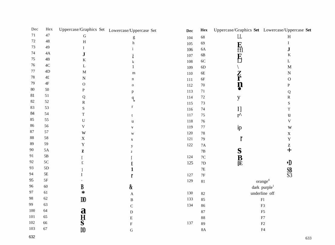
632 633
Dec
71
72
73
74
75
76
77
78
79
80
8182
83
8485
86
87
88
89
90
91
92
93
94
9596
97
98
99
100
101
102
103
Hex
47
48
49
4A
4B
4C
4D
4£
4F
50
51
52
53
54
55
56
57
58
59
5A
5B
5C
5D
5E
5F
60
61
62
63
64
65
66
67
Uppercase/Graphics Set
G
H
I
JK
L
M
NO
P
QR
S
T
U
V
wXY
z[£
]I4 -
B*DD
aHsDD
Lowercase/Uppercase Set
gh
i
j*k
1m
n
o
p
q*
r
t
uV
w
X
y2
[L
E1r
&A
B
C
D
E
F
G
Dec
104
105
106107
108
109
110
111
112
113
114
115
116
117
118
119
120
121
122
124
125
127
129
130
133
134
137
Hex
68
69
6A
6B
6C
6D
6E
6F
70
71
72
73
74
75
76
77
78
79
7A
7B
7C
7D
7E
7F
81
82
85
86
87
88
89
8A
Uppercase/Graphics Set Lowercase/Uppercase Set
LL
EfflELJ\Zrn•y
I]r̂
ip
rsB[E
orange4
dark purple1
underline off
Fl
F3
F5
F7
F2
F4
HI
JK
L
MNOP
QR
S
T
uV
wxYz+•DSBS3

Dec
139
140141
142
143
144
145
146
147
148149
150
151
152
153
154
155
156
157
158
159
160
161
162
163
164
165
166
167
168
169
Hex
8B
8C
8D
8E
8F
90
91
92
93
94
95
96
97
98
99
9A
9B
9C
9D
9E
9F
A0
Al
A2
A3
A4
A5
A6
A7
A8A9
Uppercase/Graphics Set Lowercase/Uppercase Set
F6
F8
SHIFT-RETURNswitch to uppercase
1y••riSiIHV .n
flash off1
blackcursor up
reverse offclear screen
insertbrown4
dark yellow1
light reddark gTay4
dark cyan1
medium graylight green
light bluelight gray
purplecursor left
yellow
cyanSHIFT-space
Ey—
r1
• A
634 635
Dec Hex Uppercase/Graphics Set Lowercase/Uppercase Set
170 AA 3 [ ]171 AB [B IB172 AC Ld Q173 AD ffl ffl174 AE ffl T175 AF U •176 B0 ffl ffl177 Bl ffl ffl178 B2 &H ffl179 B3 m m180 B4 C J
181 B5 C ID182 B6 LI Ll183 B7
184 B8 H n185 B9 U y186 BA • ~V\187 BB H B188 BC L3 1189 BD ffl ffl190 BE H H191 BF fij BJ192 CO H H193 Cl H A194 C2 J | B195 C3 H C196 C4 S D197 C5 H E198 C6 H F199 C7 l i G200 C8 U H201 C9 B I202 CA f? J

Notes1. For 80-column display only2. For 128 mode only3. For 64 mode only4. For 40-colunm display only
637
Dec Hex Uppercase/Graphics Set Lowercase/Uppercase Set203 CB ffl K
204 CC t ] L205 CD k | M
206 CE g ] N
207 CF |-j 0208 DO 3 P209 DI \m\ Q
210 D2 H R211 D3 m S212 D4 11 T
213 D5 H U214 D6 X V215 D7 [g w
216 D8 t X217 D9 [ J Y218 DA 3 Z219 DB + +220 DC BC B221 DD f l I f222 DE iil g |223 DF ^ jg224 E0225 El | J | j226 E2 y y227 E3 ^ •228 E4 •229 E5. O Hi
231 E7 1 [ ]232 E8 i i ^233 E9 B 5g234 EA El •235 EB DB Lfe
Dec Hex Uppercase/Graphics Set Lowercase/Uppercase Set
236 EC H ~~m237 ED t ^238 EE ffl SI239 EF U U240 F0 _T L^
241 FI a m242 F2 H ffl243 F3 tfj J !244 F4 G I !245 F5 [ I I I246 F6 | | |247 F7 H248 F8 H H249 F9 y M
250 FA Ul ^251 FB kJ B252 FC " H253 FD B ?J254 FE Fl255 FF ifl S?

Screen CodesThere are 256 screen codes for each character set; codes128-255 are the reverse images of codes 0-127. To displayany character in reverse video, simply add 128 to its screencode value. Thus, POKE 1024,1:POKE 1025,1 + 128 displaysan A and a reverse A.
The character ROM has a total of 153 different characters.In the uppercase/graphics set, the character patterns for codes32 and 96 are identical, as are those for 64 and 67, 66 and 93,101 and 116, and 103 and 106.
Dec
24
25
26
27
28
29
30
31
32
33
34
35
36
37
38
39
40
41
42
43
44
45
46
47
48
49
50
51
52
5354
55
56
Hex
18
19
1A
IB
1C
ID
IE
IF
20
21
22
23
24
25
26
27
28
29
2A
2B
2C
2D
2E
2F
30
31
32
33
34
3536
37
38
Uppercase/Graphics
X
Y
Z
[E
]t*-
!
#$%&
()
+t
-
/
0
12
3
4
5678
Set Lowercase/Uppercase Set
X
yz
[E
]T
«-space
!ft
#
$
%
&
t
(
)
•
+t
-
*
/
0
1
2
34
56
78
639
Dec Hex Uppercase/Graphics Set Lowercase/Uppercase Set0 00 @ @1 01 A a2 02 B b3 03 C c4 04 D d5 05 E e6 06 F i7 07 G g8 08 H h9 09 I i10 0A J j11 0B K k12 0C L 113 0D M m14 0E N n15 OF O o16 10 P p17 11 Q q18 12 R r19 13 S s20 14 T t21 15 U u22 16 V v23 17 W w

640 641
Dec Hex Uppercase/Graphics Set Lowercase/Uppercase Set
57 39 9 958 3A :59 3B ; ;60 3C < <61 3D = =62 3E > >63 3F ? ?64 40 g B65 41 • A66 42 I]] B67 43 H C68 44 g D69 45 —' E70 46 — F71 47 | ] G72 48 [11 H73 49 E I74 4A V j75 4B ffi K76 4C C L77 4D SJ M78 4E 2 N79 4F C 080 50 ^ P81 51 IB] Q82 52 Q R83 53 W S84 54 Hj T85 55 ffl U86 56 J£ V87 57 O W88 58 |5 | X89 59 d Y
Dec Hex Uppercase/Graphics Set Lowercase/Uppercase Set
90 5A ffl Z91 5B * +92 5C £1 £J93 5D [B T94 5E ff1 ^95 5F 15 ^96 60 SHIFT-space97 61 H | ]98 62 y H
99 63 n100 64 • •ioi 65 r r
103 67 fl •104 68 ki kaJ105 69 Fl ^106 6A • ]107 6B [B |_£108 6C ; H .109 6D [5 ^HO 6E h fflin 6F ^. y112 70 ffl ffl113 71 ffl ^H4 72 ffl T
H5 73 3] ffi116 74 Cl CH7 75 IJ IUS 76 I dii9 77 n
121 79 U Q122 7A • |Z

Dec
123
124
125
126
127
Hex
7B
7C
7D
?E
7F
Uppercase/Graphics Set
F]n
Lowercase/Uppercase Set
•
ffl
KeycodesThe 128 keyboard is arranged electrically as a matrix of 11 col-umns X 8 rows of keys. Every 1/60 second, the computerscans the keyboard to see if a key is pressed. If a key ispressed, the keyscan routine generates a value that corre-sponds to the key's position in the matrix. (The formula iskeycode = column * 8 + row, where column has a value from0 to 10, and row has a value from 0 to 7.) If no key is pressed,a value of 88 is generated. This value is stored in location 212.Location 213 will also hold the same value. The contents ofthis location can be used to determine which key is currentlybeing pressed, as an alternative to using GET (or the KernalGETIN routine inmachine language). For example, these twolines have the the same effect—to pause the program untilany key is pressed:100 GET K$:IF K$="" THEN 100100 IF PEEK(212)=88 THEN 100
Figure C-l gives the keyscan codes for the 128 keyboard.Notice that the figure shows no values for the left and' rightSHIFT keys, CONTROL, the Commodore key, and ALT. Theyare the keys which use the missing codes 15, 52, 58, 61, and80, respectively. These keys are detected later in the keyscanroutine, and location 211 is used to record their status. Thevalues found in that location are as follows:
No shift key pressedSHIFTCommodoreCONTROLALTCAPS LOCK
0124816
642 643

Appendix D
For this location the values are cumulative. If you pressboth SHIFT and CONTROL, the location will contain 1 + 4= 5. Holding down SHIFT, CONTROL, Commodore, andALT together results in a value of 15.
The other "missing" keys are not part of the keyscan ma-trix. RESTORE is connected to the CIA #2 chip, and acts bygenerating an NMI interrupt. The 40/80 column key is con-nected to the MMU chip and is read and acted upon only atpower-on or reset. The SHIFT LOCK key is not scanned; it'smerely a switch that has the effect of holding down the SHIFTkey.
644.
Musical NoteFrequenciesThe following table lists the frequencies for the standard musi-cal notes which can be produced by the 128's SID sound chip,along with the SID frequency register values required to pro-duce these sounds. The register values shown are for 128susing the NTSC (North American) video system. Refer to thediscussion of the SID chip in Chapter 8 for more informationon sound programming.
Although music is often considered an art rather than ascience, there is a precise mathematical relationship betweenthe notes in the scale. Any two adjacent notes differ in fre-quency by a factor of 2 t (1 / 12), or about 1.05946. That is,for any given note the frequency of the next higher note willbe equal to the current note frequency multiplied by 1.05946,and the frequency of the next lower note will be equal to thecurrent note frequency divided by 1.05946. Furthermore, thefrequency of a note in one octave and that of a note with thesame letter designation in a higher or lower octave will differby a factor of 2 times the number of octaves between thenotes. For example, by international convention the base fre-quency in this standard system of musical notation is the A at440 hertz (octave 3 in the table below). You'll notice that theA in octave 2 has a frequency of 220 hertz (440 / 2), and theA in octave 4 has a frequency of 880 hertz (440 * 2); the A inoctave 1 has a frequency of 110 hertz (440 / 4), and the A inoctave 5 has a frequency of 1760 hertz (440 * 4). The octavedesignations shown (0-6) correspond to those used with the Oparameter in the BASIC PLAY statement.
Note
Octave 0:CC/DDD/EE
Frequency(hertz)
32.7034.6536.7138.8941.20
Frequency(low byte)
24/$1856/$3890/$5A
126/$7E164/$A4
register value(high byte)
2/$022/$022/$022/$022/$02
645

Note
FF/GGG/AAA/BB
Octave 1:CC/DDD/EEFF/GGG/AAA/BB
Octave 2:CC/DDD/EEFF/GGG/AAA/BB
Octave 3:CC/DDD/EEFF/GG
Frequency(hertz)
43.6546.2549.0051.9155.0058.2761.74
65.4169.3073.4277.7882.4187.3192.5098.00
103.83110.00116.54123.47
130.81138.59146,83155.56164.81174.61185.00196.00207.65220.00233.08246.94
261.63277.18293.66311.13329.63349.23369.99392.00
Frequency register value(low byte) (high byte)
204/$CC247/$F7
36/$2484/$54
134/$86188/$BC245/$F5
49/$31113/$71180/$B4252/$FC
72/$48152/$98237/$ED
72/$48167/$ A 712/$0C
120/$78233/$E9
2/$022/$023/$033/$033/$033/$033/$03
4/$044/$044/$044/$045/$055/$055/$056/$066/$067/$077/$077/$ 07
98/$62225/$El105/$69248/$F8144/$9048/$30
219/$DB143/$8F78/$4E25/$19
240/$F0211/$D3
196/$C4195/$C32O9/$D124O/$F031/$1F97/$61182/$B63O/$1E
8/$088/$089/$099/$09
10/$0All/$0B11/$OB12/$0C13/$0D14/$0E14/$0E15/$0F
16/$1017/$1118/$1219/$1321/$1522/$1623/$1725/$19
(middle C)
Note
G/AAA/BBOctave 4:CC/DDD/EEFF/GGG/AAA/BB
Octave S:CC/DDD/EEFF/GGG/AAA/BBOctave 6:CC/DDD/EEFF/GGG/AAA/BB
Frequency(hertz)415.30440.00466.16493.88
523.25554.37587.33622.25659.25698.46739.99783.99830.61880.00932.33987.77
1046.501108.731174.661244.511318.511396.911479.981567.981661.221760.001864.651975.53
2093.002217.462349.322489.012637.022793.822959.953135.963322.443520.003729.313951.07
Frequency(low byte)157/$9D50/$32
223/$DF166/$A6
136/$88134/S86163/$A3224/SEO63/$3F
194/$C2107/$6B61/$3D58/$3A100/S64190/SBE76/$4C
15/$0F12/$0C70/$46
191/SBF125/$7D131/S83214/$D6122/$7A115/$73200/$C8124/$7C151/S97
3O/$1E24/$18139/$8B127/$7F251/$FB
7/$07172/$ AC243/$F3230/$E6143/$8F249/SF947/$2F
register value(high byte)26/$lA28/$lC29/$lD31/$1F
33/$2135/$2337/$2539/$2742/$2A44/$2C47/S2F50/$3253/$3556/$3859/$3B63/$3F
67/$4371/$4775/$4B79/$4F84/$5489/$5994/$5E100/$64106/$6A112/$70119/$77126/$7E
134/S86142/$8E150/$96159/$9F168/$A8179/$B3189/$BD200/SC8212/$D4225/$El238/$EE253/$FD
647
Appendix E
64/128 MemoryMap CrossReferenceThe following list provides a cross reference of the Commo-dore 64 and Commodore 128 memory maps. In addition tothe RAM locations shown, all I/O chips appear in the 128 atthe same addresses as in the Commodore 64. (When the 128is used in Commodore 64 mode, the two extra VIC chip regis-ters and the VDC 80-column chip are still available, althoughthey must be programmed directly, since there are no routinesto support them.) Also, the Kernal jump table at 65409-65525/$FF81-$FFF5 is common to both the Commodore 64 and 128.
649

s Commodore 64 address0/$00l/$013-4/$03-$04
5-6/$05-$06
7/$078/$089/$091O/SOA11/$OB12/$0C13/$0D14/$0E15/$0F16/$10
17/$1118/$1219/$1320-21/$14-$1522/$1623-24/$17-$18
25-33/$19-$2134-37/$22-$2538-42/$26-$2A43-44/$2B-$2C45-46/$2D-$2E47-48/$2F-$3049-50/$31-$32
Commodore 128 address0/$00l/$014474-4475/$117A-$117B
4476-4477/$117C-$117C
9/$0910/$OA11/$OB12/$0C13/$0DH/$0E15/$0F16/$1017/$11I8/$12
19/$1320/$142I/$1522-23/$16-$1724/$1825-26/$19-$1A
27-35/$lB-$2336-39/$24-$2740-44/$28-$2C45-46/$2D-$2E47-48/$2F-$3049-50/$31-$3251-52/$33-$34
FunctionProcessor on-chip I/O port data direction registerProcessor on-chip I/O port data registerVector: Routine to convert a number from floating point tosigned integerVector: Routine to convert a number from integer to floatingpointSearch character for scanning BASIC text inputSearch character for statement terminator or quoteColumn position of the cursor before the last TAB or SPCBASIC LOAD/VERIFY flag[ndex into the text input buffer / number of array subscriptsFlag for routines that locate or build an arrayFlag: Type of data {string OT numeric)Flag: Type of numeric data (integer or floating point)Flag for LIST, garbage collection, and program tokenizatiortFlag: Subscript reference to an array or user-defined function call(FN)Input source flag (GET, READ, or INPUT)Flag: Sign of the result of the TAN or SIN functionCurrent I/O channel {CMD logical file) numberInteger line number valuePointer to the next available space in the temporary string stackPointer to the address of the last string in the temporary stringstackDescriptor stack for temporary stringsMiscellaneous temporary pointers and save areaFloating point multiplication work areaPointer to the start of BASIC program textPointer to the start of the variable storage areaPointer to the start of the array storage areaPointer to the start of the area available for string storage
Commodore 64 address51-52/$33-$3453-54/$35-$3655-56/$37-$3857-58/$39-$3A59-60/$3B-$3C61-62/$3D-$3E63-64/$3F-$4065-66/$41-$4267-68/$43-$4469-70/$45-$4671-72/$47-$4873-74/$49-$4A75-76/$4B-$4C77/$4D78-79/$4E-$4F80-82/$50-$5283/$5384-86/$54-$5687-96/$57-$6097-101/$61-$65102/$66103/S67104/$68105-109/$69-$6D110/S6E111/$6F112/$70113-114/$71-$72115-138/$73-$8A139-143/$8B-$8F
Commodore 128 address53-54/$35-$3655-56/$37-$3857-58/$39-$3A59-60/$3B-$3C4608-4609/$1200-$12ul4610-4611/$1202-$120365-66/$41-$4267-68/$43-$4469-70/$45-$4671-72/$47-$4873-74/$49-$4A75-76/$4B-$4C77-78/$4D-$4E79/$4F80-81/$50-$5I82-84/$52-$54n.a.86-88/$56-$5889-98/$59-$6299-103/$63-$67104/$68105/$69991/$03DF106-110/$6A-$6E111/$6F112/$70113/$71114-115/$72-$73896-926/$0380-$039E4635-4639/$121B-$121F
FunctionPointer to the bottom of the string poolTemporary pointer for stringsPointer to the highest address used by BASICCurrent BASIC line numberPrevious BASIC line numberPointer to the address of the current BASIC statementCurrent DATA line numberPointer to the address of the current DATA itemPointer to the source of GET, READ, or INPUTCurrent BASIC variable namePointer to the current BASIC variable valueTemporary pointer to the index variable used by FORMath operator table displacementMask for comparison operationPointer to the current FN descriptorTemporary pointer to the current string descriptorConstant for garbage collectionJump to function instructionBASIC numeric work areaFloating point accumulator #1Floating point accumulator #1 signNumber of terms in a series evaluationFloating point accumulator #1 overflow digitFloating point accumulator #2Floating point accumulator #2 signResult of a sign comparison of FAC1 to FAC2Low byte of floating point accumulator #1 (for rounding)Series evaluation pointerSubroutine to get next BASIC text character (CHRGET)RND function seed value

toCommodore 64 address144/$90145/S91H6/$92147/$93148/$94149/$95150/$96151/$97152/$98153/$99154/$9A155/S9B156/$9C157/$9D158/$9E159/$9F160-162/$ A0-$A2163-164/$A3-$A4165/$A5166/$A6167/$A7168/$A8169/$A9170/$AA171/$AB172-173/$AC-$AD174-175/$AE-$AF176-177/$BO-$B1178-179/$B2-$B3180/$B4
Commodore 123 address144/$90145/$91146/$92147/$93148/$94149/$95150/$96151/$97152/$98153/$99154/$9A155/$9B156/$9C157/$9D158/$9E159/$9F160-162/$ A0-$A2163-164/$A3-$A4165/$A5166/$A6167/SA7168/$A8169/$A9170/$AA171/$AB172-173/$AC-$AD174-175/$AE-$AF176-177/$B0-$BI178-179/$B2-SB3180/$B4
FunctionKemal I/O status word (ST)Flag: Was STOP key pressed?Timing constant for tape readsFlag for Kerna! LOAD routine (0 = LOAD, 1 = VERIFY)Serial bus buffered character flagBuffered character for serial busCassette block synchronization numberTemporary register save areaNumber of open files / index into the file tablesDefault input device (set to 0 for the keyboard)Default output (CMD) device (set to 3 for the screen)Tape character parityFlag: Tape byte receivedKernal message control flagTape pass 1 error log indexTape pass 2 error log correction indexSoftware jiffy clockCassette/serial work bytesCassette synchronization character countdownCount of characters in tape I/O bufferRS-232 input bits / cassette temporary storage areaRS-232 input bit count / cassette temporary storageRS-232 start bit received flagRS-232 input byte buffer / cassette temporary storageRS-232 input parity / cassette leader counterPointer to the starting address of a load / screen scrollingPointer to the ending address of the load (end of program)Tape timingPointer to start of tape bufferRS-232 output bit count / cassette temporary storage
ON
Commodore 64 address181/SB3182/SB6183/$B7184/$B8185/$B9186/$BA187-188/$BB-$BC189/$BD190/$BE191/$BF192/$C0193-I94/$C1-$C2195-196/$C3-$C4197/$C5198/$C6199/$C7200/$C8201-202/$C9-$CA203/$CB204/$CC205/$CD206/$CE207/$CF208/$D0209-210/$Dl-$D2211/$D3212/$D4213/$D52H/$D6215/$D7
Commodore 12S address131/$B5182/$B6183/$B7184/$B8185/$B9186/$BA187-188/$BB-$BC189/$BD190/$BE191/$BF192/$C0193-194/$C1-$C2195-196/$C3-$C4213/$D5208/$D0243/$F32608/$OA30232-233/$E8-$E9212/$D42599/$0A272600/$0A282601/$0A292598/$0A262]4/$D6224-225/$E0-$El236/$EC244/$F4238/$EE235/$EB240/$FO
FunctionRS-232 next bit to send / tape EOT flagRS-232 output byte bufferLength of current filenameCurrent logical file numberCurrent secondary addressCurrent device numberPointer to current filenameRS-232 output parity / cassette temporary storageCassette read/write block countTape input byte bufferTape motor interlockI/O start addressTape load temporary addressesMatrix coordinate of last key pressedNumber of characters in keyboard buffer (queue)Reverse character flagPointer to end of logical line for inputCursor column and row position at start of inputMatrix coordinate of current key pressedCursor blink enable flag (0 = flashing cursor)Timer: Countdown to blink cursorCharacter under cursorFlag: Was last cursor blink on or off?Flag: Input from keyboard or screenPointer to the address of the current screen lineCursor column on current lineQuote mode flag (0 — off)Maximum length of physical screen lineCurrent cursor physical line numberTemporary storage area for last character printed

g; Commodore 64 address^ 216/$D8
217-242/$ D9-$F2243-244/$F3-$F4245-246/$F5-$F6247-248/$F7-$F8249-250/$F9-$FA251-254/$FB-$FE255-266/$FF-$010A256-317/$0100-$013D256-511/$0100-$01FF512-600/$0200-$0258601-610/$0259-$02626Jl-62O/$0263-$O26C621-630/$026D-$0276631-640/$0277-$0280641-642/$0281-$0282643-644/$0283-$0284645/$0285646/$0286647/$0287648/S0288649/$0289650/$028A651/$028B652/$028C653/$028D654/$028E655-656/$028F-$0290657/S0291
Commodore 128 address245/$F5
n.a.226-227/$E2-$E3204-205/$CC-$CD200-201 /$C8-$C9202-203/$CA-$CB251-254/$FB-$FE255-266/$FF-$010A256-217/$0100-$013D256-511/$0100-$01FF512-671/$0200-$02AO866-875/$0362-$036E876-885/$036C-$0375886-895/$0376-$037F842-851/$034A-$03532565-2566/$OA05-$OA062567-2568/$OA07-$OA082574/$OA0E241/$F12602/$OA2A2619/$0A3B2592/$0A202594/$0A222595/S0A232596/$0A24211/$D3n.a.826-827/$033A-$033B247/$F7
FunctionFlag: Insert mode (any number greater than 0 is the number ofinserts)Screen line link table / editor temporary storagePointer to the address of the current screen color RAM locationPointer to current keyboard decode tablePointer to RS-232 input bufferPointer to RS-232 output bufferFree zero-page locations for user programsWork area for floating point to ASCII conversionTape input error logMicroprocessor stack areaBASIC input bufferTable of active logical file numbersTable of device numbers for each logical fileTable of secondary addresses for each logical fileKeyboard bufferPointer to start of memoryPointer to end of memoryIEEE time-out flagCurrent foreground color for textColor of character undeT cursorTop page of screen memoryMaximum keyboard buffer sizeFlag: Which keys will repeat?Counter for timing the delay between key repeatsCounter for timing the delay until the first key repeat beginsCurrent SHI FT/CTRL/Commodore keypressLast pattern of SHIFT/CTRL/Commodore keypressVector to keyboard table setup routineFlag: Enable/disable character set switching with SHIFT-Commodore
Commodore 64 address Commodore 128 address658/$0292659/$0293660/S0294661-662/$0295-$0296663/S0297664/$0298665-666/$0299-$029A667/$029B668/$029C669/$029D670/$029E671-672/$029F-$02A0673/$02Al674/$02A2675/$02A3
676/$02A4677/S02A5678/S02A6768-769/$0300-$0301770-771/$0302-$0303772-773/$0304-$0305774-775/$0306-$0307776-777/$0308-$0309778-779/$030A-$030B
780/$030C781/$030D782/$030H
8 783/$030F
248/$F82576/$OA102577/$0All2578-2579/$OA12-$0A132780/$0A142581/$0A152582-2583/$OA16-$0A172584/$0A182585/S0A192586/$0AlA2587/S0A1B2569-2570/$OA09-$OAOA2575/$0AOF2571/S0A0B2572/S0A0C
2573/S0A0D223/$DF2563/$0A03768-769/$0300-$03ul770-771/$0302-$0303772-773/$0304-$0305774-775/$0306-$0307776-777/$0308-$0309778-779/$030A-$030B
6/$067/$078/$085/$05
FunctionFlag: Screen scroll enabledRS-232 control registerRS-232 command registerRS-232 Nonstandard bit timingRS-232 status registerNumber of bits left to be sent/receivedTime required to send a bitIndex to end of RS-232 input bufferIndex to start of RS-232 input bufferIndex to start of RS-232 output bufferIndex to end of RS-232 output bufferSave area for IRQ vector during cassette operationsRS-232 interrupts enabledCIA #1 control register B storage during cassette operationsSave area for CIA #1 interrupt control register during cassettereadSave area for CIA #1 control register A during cassette readTemporary index to the next 40-column line for screen scrollingPAL/NTSC HagVector to print BASIC error message routineVector to main BASIC program loopVector to routine that crunches the ASCII keywords into tokensVector to routine that lists BASIC program tokensVector to routine that executes next BASIC program tokenVector to routine that evaluates a single-term arithmeticexpressionStorage for A register (accumulator)Storage for X index registerStorage for Y index registerStorage for status register

Appendix F
BASIC KeywordIndex
656
The following table lists all of the BASIC 7.0 keywords in al-phabetical order, along with their corresponding tokens andthe addresses of the routines called to perform each token'soperation.
KeywordABSANDAPPENDASCATNAUTOBACKUPBANKBEGINBENDBLOADBOOTBOXBSAVEBUMFCATALOGCHARCHR$CIRCLECLOSECLRCMDCOLLECTCOLLISIONCOLORCONCATCONTCOPYCOSDATADCLEAR
Token182/$B6175/$AF254/$FE + 14/$0E198/$C6193/$C1220/SDC246/$F6254/$FE + 2/$02254/$FE + 24/$18254/$FE + 25/$19254/$FE + 17/$ll254/$FE + 27/$lB225/$El254/$FE + l6/$10206/$CE + 3/$03254/$FE+12/$0C224/$E0199/$C7226/$E2160/$AO156/$9C157/$9D243/$F3254/$FE + 23/$17231/SE7254/$FE+19/$13154/$9A244/$F4190/$BE131/S83254/$FE + 21/$15
Address35972/$8C8419593/$4C8941268/$A13434423/$867738067/$94B322901/$597541852/$A37C27593/$6BC9[1]21135/S528F41496/$A21829493/$733525271/$62B741416/$A1C833660/S837C41086/$A07E26583/$67D734239/$85BF26254/$668E37274/$919A20984/$51F821824/$554041775/SA32F29028/$716427106/$69E241826/$A36223136/$5A6041798/$A34637897/$940921135/I528F41762/$A322
657

KeywordDCLOSEDECDEFDELETEDIMDIRECTORYDLOADDODOPENDRAWD5AVEDVERIFYELSEENDENVELOPEERR$EXITEXPFASTFETCHFILTERFNFORFREGETGOGOSUBGOTOGRAPHICGSHAPEHEADERHELPHEX$IFINPUTINPUT#INSTRINTJOYKEYLEFTSLENLETLISTLOAD
658
Token254/$FE+15/$0F2O9/$D1150/$96247/$F7134/$86238/$EE240/$F0235/$EB254/$FE+13/$0D229/$E5239/$EF254/$FE + 20/$14213/$D5128/$80254/$FE + 10/$OA211/$D3237/$ED189/IBD254/$FE + 37/$25254/$FE + 33/$21254/$FE + 3/$03165/$A5129/$81184/$B8161/$A1203/$CB141/$8D137/$89222/$DE227/$E3241/$F1234/$EA210/$D2I39/S8B133/$85132/$84212/SD4181/$B5207/$CF249/$F9200/$C8195/$C3136/$88155/$9B147/$93
Address
41327/$A16F32886/$807634042/$84FA24199/$5E8722651/$587B41086/$A07E41383/$A1A724544/$5FE041245/$A11D26519/$679741356/$A18C4138O/$A1A421393/$539119405/$4BCD28865/$70Cl33014/$80F624633/$603936915/$903330643/$77B343556/$AA2428742/$704634107/$853B24057/$5DF932768/$800022034/$5612[2]23101/$5A3D22991/$59CF23003/$59DB27482/$6B5A25997/$658D4I575/$A26722918/$598633090/S814221189/$52C522H4/$566222088/$564839361/S99C136091/$8CFB33283/$820324842/$610A34262/$85D634408/$866821446/$53C620706/$50E237164/$912C
Keyword
LOCATELOGLOOPMID$MONITORMOVSPRNEWNEXTNOTOFFONOPENORPAINTPEEKPENPLAYPOINTERPOKEPOSPOTPRINTPRINT*PUDEFQUITRCLRRDOTREADRECORDREMRENAMERENUMBERRESTORERESUMERETURNRGRRIGHTSRNDRREGRSPCOLORRSPPOSRSPRITERUNRWINDOWSAVE
Token
23O/SE6188/$BC236/$EC202/$CA250/$FA254/$FE + 6/$06162/$A2130/$82168/$A8254/$FE + 36/$24145/$91159/$9F176/$B0223/SDF194/$C2206/$CE+4/$04254/$FE + 4/$04206/$CE + 10/$0A151/S97185/$B9206/$CE + 2/$02153/$99152/$98221/$DD254/$FE + 30/$lE205/$CD208/$D0135/$87254/$FE + 18/$12143/$8F245/$F5248/$F8140/$8C214/$D6142/$8E204/$CC201/$C9187/$BB254/$FE + 9/$09206/$CE + 7/$07206/$CE + 5/$05206/$CE + 6/$06138/$8A206/$CE + 9/$09148/$94
Address
26965/$695535274/$89CA24714/$608A[3]45056/$B00027846/$6CC620950/$51D622516/$57F4 [4]31024/$793018502/$4846 [5]21411/$53A3 [6]37261/$918D19590/$4C8625000/$61A832965/$80C533454/$82AE28129/S6DE133530/$82FA32997/$80E534000/$84DO33357/$824D21850/$555A21818/$553A24372/$5F3418502/$4846 [5]33179/$819B39692/$9B0C22185/S56A941687/$A2D721149/$529D41838/$A36E23288/$5AF823242/$5ACA24418/$5F6221090/$526233154/$818234314/$860A33844/$843422717/$58BD33633/$836133687/$839733566/$831E23195/$5A9B33799/$840737138/$9112
659

KeywordSCALESCNCLRSCRATCHSGNsrNSLEEPSLOWSOUNDSPC(SPRCOLORSPRDEFSPRITESPRSAVSQRSSHAPESTASHSTEPSTOPSTR$SWAPSYSTAB(TANTEMPOTHENTOTRAPTROFFTRONUNTILUSINGUSRVALVERIFYVOLWAITWHILEWIDTHWINDOWXOR+*/
660
Token233/$E9232/$E8242/$F2180/$B4191/$BF254/$FE + ll/$0B254/$FE + 38/$26218/$DA166/$A6254/$FE + 8/$08254/$FEH-29/$lD254/$FE + 7/$07254/$FE + 22/$16186/$BA228/$E4254/$FE + 31/$lF169/$A9144/$90196/$C4254/$FE + 35/$23158/$9E163/$A3192/$C0254/$FE + 5/$05167/$A7164/$A4215/$D7217/$D9216/$D8252/$FC251/$FBI83/$B7197/$C5149/$95219/$DB146/$92253/$FD254/$FE + 28/$lC254/$FE + 26/$lA206/$CE + 8/$08170/$AA171/$AB172/$AC173/$ AD174/$AE
Address26976/$69602 725 7/$ 6A 7941633/$A2A135941/$8C6537904/$941027607/$6BD730660/$77C429164/$71EC[7]29072/$719029554/$737227727/$6C4F30444/$76EC36791/$8FB725643/$642B43551/$AA1F[8]19403/$4BCB34222/$85AE43561/$AA2922661/$5885m37977/$945928631/$6FD7[9][10]24397/$5F4D22711/$58B722708/$58B4
m4632/$121832842/$804A37161/$912929125/$71C527693/$6C2D[11]29110/$71B629388/$ 72CC33761/$83E134888/$884834865/$883135367/$8A2735660/$8B4C36801/S8FC1
Keyword Token Address< 179/$B3
178/$B2> 177/$B1K 255/$FF
19638/$4CB619638/$4CB619638/$4CB6[12]
Notes:1. Normally handled during IF execution. When encountered
outside IF processing, the target routine merely prints aSYNTAX ERROR message.
2. There are no separate tokens for the keywords GET* andGETKEY; both are handled as special cases during GETexecution. GET* is represented by a GET token followedby a # character (code 35/$23). GETKEY is represented bya GET token followed by a KEY token (249/SF9).
3. Can be used as either a statement or a function. The rou-tine at 22785/$5901 handles processing as a statement;when a function, the routine at 34332/S861C is used.
4. Can also be used in conjunction with the RESUMEstatement.
5. Defined but not implemented. The target routine merelyprints an UNIMPLEMENTED COMMAND ERRORmessage.
6. Can also be used in conjunction with most disk commandsto specify the device (unit) number.
7. Processed during PRINT execution.8. Processed during FOR execution.9. Processed during IF execution.
10. Processed during the execution of several other keywordswhich accept TO as part of a valid statement: DRAW, FOR,GO, and assorted disk commands (BACKUP, BSAVE,CONCAT, COPY, and RENAME).
11. Processed during DO or LOOP execution.12. Processed during the operand evaluation routine (EVAL),
30935/$78D7.
661
i
More fun...More challenge...Mote all new programseach and every month.Subscribe to COMPUTEVs Gazettethrough this special money-saving in-troductory offer—and start unleashingthe full power of your Commodorecomputer.
Month after month, look toCOMPUTERS Gazette to deliver thelatest inside word on everything fromshort programming tips to the bestnew software. Our expert analysis andinsights mean you have more fun...getmore enjoyment...more of what youbought your computer for.
As a subscriber, you also receiveup to 20 all-new, action-packed pro-grams each month. Every big issue ofCOMPUTEVs Gazette comes completewith a steady supply of the mostuseful, the most entertaining, the
SubscriptionSavings Card
highest quality programs like NumberQuest. Address File, Treasure Hunt.Castle Dungeon, Vocab Builder,SpeedScript, and hundreds of othereducational, home finance, and gameprograms.
So subscribe today—and unleashthe hidden power of your Commodorecomputer, Return the card below—orcall 1-800-247-5470 (in Iowa. 1-800-532-1272). Do it now.
YES!n Payment enclosed • Bill me • Charge my VISA/MasterCard
I know a great dealwhen 1 see one. Signme up for 12 big issuesof COMPUTEVs Gazettefor |ust $18.1 save 50%off the newsstand price.
Credit Card #_ _Exp. Date_
Signature-
Name_
Address.
City_ -Sta te . _Zip_
Outside US A please aJJ S6-..U.S (per year (or postage.

Say YES now toCOMPUTE'S
You can search far and wide and yousimply want find a better magazine...abetter source of insightful, stimulating,usable information for your Com-modore computer than COMPUTERSGazette.
COMPUTE'S Gazette worksharder...digs deeper...researchesfurther—all to help guarantee that youget the absolute most from your Com-modore.
Subscribe today and each and ev-ery month you 11 receive up to 20 all-new action-packed programs. That's upto 200 programs each year—game pro-grams...education programs...home ap-plications programs...personal andbudgeting programs...sorting and filingprograms.
Add it up for yourself. Where elsecan you get exciting programs eachmonth...expert advice...insightfulanalysis...up-to-the-minute softwarereviews and so much more—all forjust $18.
So why wait. Subscribe now toCOMPUTEfs Gazette—and get themost from your Commodore computer.Return card below—or call 1-SO0-247-5470 (in Iowa. 1-800-532-1272).
BUSINESS REPLY MAILFIRST CLASS PERMIT NO. 7551 DES MOINES. lA
NO POSTAGENECESSARYIF MAILED
IN THEUNITED STATES
POSTAGE: WILL BE PAID BY ADDRESSEE
COMPUTERS GazettePO Box 10775Des Moines, IA 50347-0775
I J . I . I I II..J..M...IM., j . . .n . < . i . i . i . . . r . i i
Appendix G
Index of Locationsand RoutinesChapter 2: Common Working Storage
so
123-4567g9910111213141516171819202122-232425-2627-3536-3738-3940-44
45-4647-4849-5051-5253-5455-5657-5859-6061-6263-6465-6667-6869-7071-72
$01$02$03-$04$05$06$07$08$09$09$0A$0B$0C$0D$0E$0F$10$11$12$13$14$15$16-$17$18$19-$1A$lB-$23$24-$25$26-$27$28-$2C
$2D-$2E$2F-$30$31-$32$33-$34$35-$36$37-$38$39-$3A$3B-$3C$3D-$3E$3F-$40$41-542$43-$44$45-$46$47-$48
Data direction register for processor's on-chip I/OportData register for processor's on-chip I/O portTarget bank for JMPFAR and JSRFARTarget address for JMPFAR and JSRFARStatus register storage for JMFFAR and JSRFARAccumulator storage for JMPFAR and JSRFARX register storage for JMPFAR and JSRFARY register storage for JMPFAR and JSRFARStack pointer storage for JSRFAR and monitorWorking storage for various routinesWorking storage for various routinesCurrent screen column for TAB and SPC calculationsBASIC LOAD/VERIFY flagWorking storage for various routinesArray dimension flagVariable type flagNumeric type flagWorking storage for various routinesInteger/subscript prohibit flagInput source flagComparison type flag/Tangent sign flagLogical file number for BASIC input and outputInteger value of ASCII digit stringPointer into temporary string descriptor stackPointer to most recent descriptor stack entryTemporary string descriptor stackMultipurpose address pointerMultipurpose address pointerTemporary storage area for multiplication anddivisionStart-of-BASIC-program pointerStart-of-variables pointerStart-of-arrays pointerStart-of-free-memory pointerBottom-of-string-space pointerTemporary pointer into the string poolTop-of-memory pointerCurrent BASIC line numberPointer for main BASIC character retrieval routineWorking pointer for varoious routinesline number of current DATA statementPointer to next DATA itemText pointer for inputCurrent variable name
663

73-7475-7677-787980-8180-8482-838586-8889-9390-9192-9393-9594-9894-959596-9896-10497-9899-103304105
106-110111112112-113113114-115116-117118119120121122122-124125-126127128128-129130131132133134135-136137-138139140-141142-143144145146147148K 9
$49-$4A$4B-$4C$4D-$4E$4F$50-$51$50-$54$52-$53$55$56-$58$59-$5D$5A-$5B$5C-$5D$5D-$5F$5E-$62$5E-$5F$5F$60-$62$60-$68$61-$62$63-$67$68$69
$6A-$6E$6F$70$70-$71$71$72-$73$74-$75$76$77$78$79$7A$7A-$7C$7D-$7E$7F$80$80-$81$82$83$84$85$86$87-$88$89-$8A$8B$SC-$8D$8E-$8F$90$91$92$93$94$95
Pointer to variable descriptorVariable descriptor pointer and working storageTemporary storage for text pointerRelational operator flagDefined function pointer and working pointerTemporary storage for floating point valueVariable address storage and working pointerHELP flagBASIC function execution vectorFloating point work areaMultipurpose working pointerMultipurpose address pointerString length and pointer for MID$Temporary storage for floating point valueWorking pointer for garbage collectionDecimal point positionSubstring length and pointer for MID$Monitor zero-page pointers and working storageMultipurpose address pointerFloating point accumulator 1Sign of FAC1Sign flag during conversion/Count of terms in seriesevaluationFloating point accumulator 2Sign of FAC2Sign comparison flagMultipurpose address pointerRounding flag for FAC1Multipurpose address pointer and working storageStep value for autoincrementGraphics area flagGeneral purpose working storageString offset pointerMultipurpose temporary storageIndex into input buffer for monitorDescriptor for disk error string DS$BASIC runtime stack pointerRUN mode flagDecimal point positionParameter flags for DOS support commandsStorage for processor stack pointerColor source for current graphics commandColor source 2 storageColor source 3 storageCurrent foreground color (source 1) storageHorizontal scaling factorVertical scaling factorPAINT mode flagAddress pointer for graphics routinesTemporary storage for graphics routinesStatus flag for tape and serial bus operationsScan value of STOP key columnTape timing adjustment factorKernal load/verify flag/Monitor operation flagSerial deferred character flagSerial character buffer
664
150151152153154155156157158159160-162163
164
165
166167
$96$97$98$99$9A$9B$9C$9D$9E$9F$A0-$A2$A3
$A4
$A5
$A6$A7
168 $A8
169
170
171
172-173172-175174-175
176177178-179180
181
182
183184185186187-188189
190191192193-194
$A9
$AA
$AB
$AC-$AD$AC-$AF$AE-$AF
$B0$B1$B2-$B3$B4
$B5
$B6
$B7$B8$B9$BA$BB-$BC$BD
(BE$BF$C0$C1-$C2
195-196 $C3-$C4
Cassette block synchronization countTemporary register storageNumber of files currently openCurrent input deviceCurrent output deviceTape character parityTape dipole received flagKemal message control flagTape pass 1 error-log pointerTape pass 2 error-log pointerSoftware jiffy clockTape: Count of bits to be read or writtenSerial: EOI flagTape: Half-cycle indicatorSerial: Byte receivedTape: Leader synchronization countdownSerial: Count of bits to sendPointer into cassette bufferTape: Leader clipole count/block indicatorRS-232: Current bit receivedTape: Half-cycle indicator for writing/error flag forreadingRS-232: Count of bits remaining to be receivedTape: Word marker flag/half-cycle flagRS-232: Start bit received flagTape: Read phase flagRS-232: Assembly byte for received bitsTape: Leader dipole counter / checksum work byteRS-232: Received byte parityKernal working address pointerWork area for disk bootingKemal working storage: Used to hold the ending ad-dress for SAVE [$F53E]Kernal address pointerTEMPPointer to cassette bufferTape: leader/data flagRS-232: Count of bits transmittedTaper Leader completed flagRS-232: Next bit to sendTape: Error flag / end of block flagRS-232: Character being sentLength of current filenameLogical file numberCurrent secondary addressCurrent device numberPointer to start of filenameTape: Byte read from tape / byte to be written to tapeRS-232: Parity calculation working storageSerial: Current byte during burst mode loadBlock countDrive number (ASCII) for PHOENIXTape motor interlockKernal work pointer: Used to hold starting address forsaveKemal work pointer (starting address for load)
665

197 $C5
198199
200-201202-203204-205206-207208209
210211212213214215216217218-223224-225
226-227
228229230231232233234235236237238239240241242243244245246247248249250251-254255-266256-511256-268256-317272-290291-310294
$C6$C7
$C8-$C9$CA-$CB$CC-$CD$CE-$CF$D0$D1
$D2$D3$D4$D5$D6$D7$D8$D9SDA-$DF$EO-$E1
$E2-$E3
$E4$E5$E6$E7$E8$E9$EA$EB$EC$EDSEESEF$F0$F1$F2$F3$F4$F5$F6$F7$F8$F9$FAtFB-SFE$OOFF-$010A$0100-$0IFF$0100-$010C$0100-$013D$0110-$0122S0I23-S0136$0126
Bit read from tape / checksum of block written totapeBank where data for save, load, or verify is foundBank where filename for open, save, load, or verify isfoundPointer to RS-232 input bufferPointer to RS-232 output bufferPointer to current keyboard decode tablePointer for Kern a 1 PR1MM routineNumber of characters in the keyboard bufferNumber of characters pending from programmablekey stringPointer into the programmable key definition areaShift key status flagCurrent key pressed (matrix value)Last key pressedInput source flagActive screen flagMode flag for 40-column screenCHAREN bit shadow5creen editor zero page work areaPointer to first screen memory location for currentlinePointer to first attribute memory location for currentlineBottom margin of current windowTop margin of current windowLeft margin of current windowRight margin of current windowCursor row for start of inputCursor column for start of inputColumn of last nonspace character on logical lineCursor rowPosition of cursor within current logical lineMaximum number of rows allowed in output windowMaximum number of columns allowed per rowCharacter to printLast character printedAttribute of current characterTemporary storage for attribute byteReverse mode flagQuote mode flagNumber of pending insertsAutoinsert mode flagCase switching/scroll pause control flagScroll/link control flagBell enable flagUnusedUnusedAssembly area for numeric stringsProcessor stack areaAssembly area for disk boot commandTape error logDOS command work areaPRINT USING work areaCommand type indicator for PLAY processing
311-507512-672673674-686687-701702-716
717-738739-763764-765766-767768-769770-771772-773774-775776-777778-779780-781782-783784-785786-787788-789790-791792-793794-795796-797798-799800-801802-803804-S05806-807808-809810-811812-813814-815816-817818-819820-821822-823824-825826-827828-829830-841842-851852-861862-865866-875876-885886-895896-926927-977978-980981982-985986987-990
$0137-$01FBJ0200-S02AOS02A1$02A2-$02AE$02AF-$02BD$02BE-$02CC
$02CD-$02E2$02E3-$02FB$02FC-$02FD$02FE-$02FF$0300-$0301$0302-$0303$0304-$0305$0306-$030;$0308-$0309$030A-$030B$030C-$030D$030E-$030F$0310-$0311$0312-$0313$0314-$0315$0316-$0317$0318-$0319$031A-$031B$031C-$031DS031E-S031F$0320-$0321$0322-$0323$0324-$0325$0326-$0327$0328-$0329$032A-$032B$032C-$032D$032E-$032F$0330-$0331$0332-$0333$0334-$0335$0336-$O337$0338-$0339$033A-$033B$033C-$033D$033E-$0349$034A-$0353$0354-$035D$035E-$0361$0362-$036B$036C-$0375$0376-$037F$0380-$039E$O39F-$O3D1$03D2-$03D4$03D5$03D6-$3D9$03DA$03DB-$03DE
666
Stack space used by BASICBASIC and monitor input bufferUnusedRetrieves a value from any bankStores a value in any bankCompares the accumulator contents against a valuefrom any bankCalls a subroutine in any bankJumps to a routine in any bankIndirect vector for extended functionsUnused indirect vectorIndirect vector in BASIC ERROR routineIndirect vector in BASIC MAIN routineIndirect vector in BASIC CRUNCH routineIndirect vector in BASIC QPLOP routineIndirect vector in BASIC GONE routineIndirect vector in BASIC EVAL routineIndirect vector for tokenizing new keywordsIndirect vector for listing new keywordsIndirect vector for executing new statementsUnusedIndirect vector to IRQ handling routineIndirect vector to BRK handling routineIndirect vector to NMI handling routineIndirect vector in Kernal OPEN routineIndirect vector in Kemal CLOSE routineIndirect vector in Kemal CHKIN routineIndirect vector in Kernal CKOUT routineIndirect vector in Kernal CLRCH routineIndirect vector in Kemal BASIN routineIndirect vector in Kemal BSOUT routineIndirect vector in Kernal STOP routineIndirect vector in Kemal GETIN routineIndirect vector in Kemal CLALL routineIndirect vector in monitor EXMON routineIndirect vector in Kernal LOAD routineIndirect vector in Kemal SAVE routineScreen editor indirect vectorScreen editor indirect vectorScreen editor indirect vectorScreen editor indirect vectorScreen editor indirect vectorScreen editor indirect vectorKeyboard bufferTab stop bitmapLine link bitmapLogical file number table for currently open filesDevice number table for currently open filesSecondary address table for currently open filesCHRGET (main BASIC character retrieval routine)Alternate BASIC character retrieval subroutinesNull descriptorBank number for PEEK and POKEPointers for INSTR evaluationString block flagTemporary storage for SHAPE data
667

991992-993994995996-10071008-10201021-1023
Chapter1024-20232024-25592560-25612562256325642565-25662567-25682569-2570
25712572257325742575257625772578-2579258025812582-2583258425852586258725882589-2591259225932594259525962597259825992600260126022603260426052606260726082609-2610
$03DF$03E0-$03El$03E2$03E3$03E4-$03EF$03FO-$03FC$03FD-$03FF
3: Bank 0$0400-07FF$0800-$09FF$OA00-$0AOl$OA02$0A03$0A04$0A05-$OA06$0AO7-$0A08$OA09-$OAOA
$OA0B$OA0C$OA0D$0A0E$0A0F$OA10S0A11$0A12-$0A13S0A14$0A15$OA16-$0A17$0A18$0A19$OA1A$OA1BJ0A1C$OA1D-$OA1F$0A20$0A21$0A22$0A23$0A24$0A25$0A26$0A27$0A28$0A29$0A2A$0A2BS0A2C$0A2D$0A2E$0A2F$0A3O$0A31-$OA32
Floating-point overflow byteTemporary pointer storageStandard bitmap color fill valueMulticolor bitmap color fill valueUnusedDMA—CALL execution routineUnused
Working StorageDefault VIC screen memoryBASIC runtime stackBASIC restart vectorMemory initialization status flagPAL/NTSC flagSystem initialization status flagKernal MEMBOT pointerKemal MEMTOP pointerTemporary storage for ILRQ vector during tapeoperationsCIA #1 control register A logCIA #1 interrupt control register logCIA #1 timer A status logIEEE timeout flagRS-232 activity flagRS-232 control registerRS-232 command registerRS-232 baud rate factorRS-232 status registerRS-232 bit countR5-232 baud rate timing constantIndex to firs! character in RS-232 input bufferIndex to last character in RS-232 input bufferIndex to first character in RS-232 output bufferIndex to last character in RS-232 output bufferFast serial mode flagSoftware jiffy timerMaximum number of keys in the keyboard bufferScroll pause flagKey repeat flagCountdown between key repeatsCountdown until key repeating beginsDelay between case switching repeatsCursor blink flagCursor enable flagCursor blink countdownCharacter under cursorColor under cursorVDC cursor modeVIC text screen and character baseVIC bitmap and video matrix baseStarting page for VDC screen memoryStarting page for VDC attribute memoryEnding row for screen inputTemporary storage for 80-column memorymanipulation
668
/2611261226132614261526162617261826192620-26212622-26232624-26502651-26552656-26652666-26692670-26872688-27032688-27192720-27272720-2729273027312732-2734273527362737273827392740274127422743-27452746-275127522753-275627572758-28152816-307]3072-33273328-35833584-40954096-43514352-44004401-44024403-44044405-44064407-44084409-445544564457445844594460446144624463
S0A33$0A34$0A35$0A36$0A37$0A38$0A39$0A3A$0A38$0A3C-$0A3D$0A3E-$0A3F$0A40-$0A5A$0A5B-$0A5F$0A60-$0A69$0A6A-$0A6D$0A6E-$0A7F$OA80-$OA8F$0A80-$0A9F$0AA0-$0AA7$0AA0-$0AA9$0AAA$0AAB$OAAC-$0AAE$0AAF$OAB0$0ABl$0AB2$0AB3$0AB4$0AB5$0AB6$0AB7-$0A39$OABA-$0ABF$0AC0$0ACl-$0AC4$0AC5S0AC6-$0AFF$OBO0-$0BFFS0C00-SOCFF$0DO0-$0DFF$0E00-$OFFF$1000-$lFFF$1100-$1130$1131-$1132$1133-$1134$1135-$U36$1137-$1138$1139-$1177$1168$1169$116A$116B$116C$116D$116E$116F
Attribute of current cursor positionScan line for screen splitTemporary storage for X registerJiffy clock compensation flagTemporary storage for clock rate registerTemporary storage for sprite enable registerTemporary storage for VIC control registerCustom mode flagStarting page for 40-coiumn screen memoryWorking pointer into 80-column memoryUnusedScreen editor variable storage for the inactive screenUnusedStorage for inactive tab stop bitmapStorage for inactive line link bitmapUnusedFilename buffer for load, save, or verifySearch pattern bufferWorking storage for base conversionInstruction assembly bufferInstruction format flagInstruction lengthThree-character mnemonic patternTemporary storage for X registerUnusedCalculated opcodeTemporary storage for X registerTransfer direction flagDigit counterTemporary storage for parameter conversionNumber of bits per digit for baseMonitor temporary storageUnusedCounter for function ROM testingTable of identifiers for function ROMsDK_FLAGUnusedCassette buffer/disk boot bufferRS-232 input bufferRS-232 output bufferSprite pattern storage areaProgrammable key definition storage areaDOS command assembly areaBitmapped screen pixel cursor horizontal positionBitmapped screen pixel cursor vertical positionFinal horizontal pixel position for graphics operationsFinal vertical pixel position for graphics operationsWorking storage for assorted graphics routinesStarting page for character pattern definitionsBit counter for shape retrievalScaling flagLine width for bitmapped graphics routinesBOX fill flagBit mask valueTemporary storage for assorted routinesTrace mode flag
669

4464-446744684469-44704471447244734474-44754476-44774478-45654566-45824583-45844585-45864587458845894590-46074608-46094610-46114612-461546164617-46184619-46204621
4622-46234624-46254626-46274628-46294630-46314632-46344635-46394640464146424643-46484649-4650465146524653-465446554656-465846594660-4661466246634664466546664667-466946704671-47204721-47224723472447254726-4728
$1170-$1173$1174$1175-$1176$1177$1178$1179$117A-$117B$117C-$117D$117E-S11D5$11D6-$1IE6$11E7-$1IE8$11E9-$11EA$11EB$11EC$11ED$11EE-$11FT$1200-$1201$1202-$1203$1204-$!207$1208$1209-$120A$120B-$120C$120D
$120E-$120F$1210-$1211$1212-$1213$1214-$1215$1216-$1217$1218-$121A$121B-$121F$1220$1221$1222S1223-$1228$1229-$122AS122B$122C$122D-$122E$122F$1230-$1232$1233$1234-$1235$1236$1237$1238$1239$123A$123B-$123D$123E$123F-$1270$1271-$1272$1273$1274$1275$1276-$!278
Working storage for RENUMBERLoop counter for reading directory entriesBlock count for directory entryWorking storage for graphics parameter scalingWorking storage for graphics parameter evaluationWorking storage for graphics parameter evaluationPointer to floating point-to-integer conversion routinePointer to integer-to-floating poinl conversion routineSprite movement control dataShadows for VIC sprite position registersShadows for VIC sprite collision registersShadow for VIC light pen registersStarting page for alternate character set during CHAKStarting page for default character set during CHARChannel number for BASIC relative file operationsUnusedline number where program stoppedPointer to the start of current lineCharacter definitions for PRINT USINGNumber of most recent errorLine number where most recent error occurredTarget line number for TRAP statementTemporary storage for high byte of TRAP linenumberPointer to start of statement where last error occurredEnd-of-program pointerTop-of-BASIC pointerTemporary text pointer storage for DOTemporary line number storage for DOUSR function jump vectorSeed value for random number generationDegrees between segments for CIRCLE routineUnusedTempo setting for PLAY statementDurations for currently active notesDuration of current noteOctave for current noteSharp/flat flagFrequency for current noteVoice number for current noteWaveforms for current notesDotted note flagCurrent filter cutoff frequencyCurrent resonance settingCurrent filter typeFilter type indexTemporary storageCurrent instrument numberEnvelope parameters for current instrumentIndex into instrument table for current instrumentInstrument parameter tablesCurrent filter cutoff frequencyCurrent filter control and resonance settingCurrent filter type selectionCurrent SID chip volume settingCollision flags
670
4729-47344735473647374738-47704771-4776478547864787-4790
4791-48064791-48544854-485748584859486048614862-4863
Chaptei1638416387163901639316416164191645316658167621678116795168271697716999170171710217162173281735617378174311792918121181721824218172183171845418472185021850719074191031919019381
$1279-$127D$127F$1280$1281S1282-S12A2$12A3-$12A8$12B1$12B2$12B3-$12B6
$12B7-$12C6$12B7~$12F6$12F6-$12F9S12FA$12FB$12FC$12PD$12FE-$12FF
5: BASIC$4000$4003$4006$4009$4020$4023$4045$4112$417A$418D$419B$41BB$4251$4267$4279$42CE$430AS43B0$43CC$43E2$4417$4609$46C9$46FC$4742$46FC$478D$4816$4828$4846$484B$4A82$4A9F$4AF6S4BB5
Target line numbers for COLLISIONCollision enable flagCollision type indexVoice for current SOUND statementTable of SOUND statement settingsParameters for most recent SOUND statementTemporary storage for POT and PEN routinesTemporary storage for POT routineTemporary parameter storage for WINDOWstatementFilename buffer for DOS support commandsSprite pattern storageSprite pattern suffixSprite mode indicator for SPRDEFSprite pattern line count for SPRDEFSprite number for SPRDEFBASIC IRQ activity flagUnused
BASIC cold-start entry pointBASIC warm-start entry pointBASIC IRQ entry pointPerforms a warm start of BASICUnusedPerforms a cold start of BASICInitializes BASIC pointers and constantsInitializes SID registers and sound routine locationsInitializes MMU preconfiguration registersInitializes sprite speed and direction tableDisplays the power-on messageText for power-on messageInitializes BASIC indirect vectorsTable of default vector valuesText for character retrieval routinesAssorted character retrieval subroutinesTokenizes keywords in lines of BASIC program textHandles extended tokensDeletes a character in the input bufferSearches keyword tables for matchBASIC keyword tablesTable of extended token statementsTable of extended token functionsTable of statement dispatch addressesTable of statement dispatch addressesTable of statement dispatch addressesTable of function dispatch addressesTable of function dispatch addressesTable of operator priorities and dispatch addressesPrints unimplemented command messageTable of BASIC error messagesSets pointer to error messageMain BASIC statement execution routineExecutes the next BA5IC statementTests for RUN/STOP keypress
671

1940319447195871959019593196381975419767197701977219836198951993820303203712039420478205032056920580206402070620771209502098421076210902113521149211892128021393214112144621818218242184422034
22088221142218522474
225162264822661227082271722785229012291822956
2299]23003
$4BCB$4BF7$4C83$4C86$4C89$4CB6$4D2A$4D37$4D3A$4D3C$4D7C$4DB7$4DE2$4F4FS4F93$4FAA$4FFE$5017$5059$5064$50AO$50E2$5123$51D6$51F8$5254$5262$528F$529D$52C5$5320$5391$53A3$53C6$553A$5540$5554$5612
$5648$5662$56A9$57CA
$57F4$5878$5885$58B4$58BD$5901$5975$5986$59AC
$59CF$59DB
Handles the STOP and END statementsHandles the execution of function keywordsDisplays the SYNTAX ERROR messageHandles the OR logical operatorHandles the AND logical operatorHandles relational operators (<, —, >)Prints the READY promptEnters MAIN with a READY promptDisplays an OUT OF MEMORY error messageHandles BASIC errorsPrints a specified error messageHandles immediate mode and program line entryAdds or deletes BASIC program linesRelinks BASIC program linesReads a line of input into the bufferSearches for a particular token in the runtime stackDecrements the runtime stack pointerChecks for available string spaceIncrements runtime stack pointerSearches program text for a specified line numberCreates integer value from a character stringHandles the LIST statementLists a single BASIC program lineHandles the NEW statementHandles the CLR statementResets the CHRGET text pointerHandles the RETURN statementHandles the BEND and DATA statementsHandles the REM statementHandles the IF statementSkips a BEGIN-BEND blockHandles the ELSE statementHandles the ON statementHandles variable value assignmentsHandles the PRINT* statementHandles the CMD statementHandles the PRINT statementHandles the GET statement (also GET# andGETKEY)Handles the ENPUT# statementHandles the INPUT statementHandles the READ statementMoves the CHRGET text pointer to the next DATAstatementHandles the NEXT statementHandles the DIM statementHandles the SYS statementHandles the TRON and TROFF statementsHandles the RREG statementHandles MID$ when used as a statementHandles the AUTO statementHandles the HELP statementHighlights the portion of a listed line containing anerrorHandles the GOSUB statementHandles the GOTO statement
2306923101231362316923195232422328023288240572419924372243972441824544246332471424801248422498925000252712564325997262542644326519265832696526976270962710627212
2722827257274822759327607276932772727846281292863128644286892874228865290282907229110291252916429388294932955430444
$5A1DS5A3D$5A60$5A81$5A9B$5ACA$5AF0$5AF8$5DF9S5ES7$5F34$5F4D$5F62$5FE0$6039$608A$6OE1$610A$619D$61A8$62B7$642B$65 8D$668E$6750$6797$67D7$6955$6960$69D8$69E2$6A4C
$6A5C$6A79$6B5A$6BC9$6BD7$6C2D$6C4F$6CC6$6DE1$6FD7$6FE4$7011$7046$70Cl$7164$7190$71B6$71C5$71EC$72CC$7335$7372$76EC
Places RETURN parameters in the runtime stackHandles the GO statementHandles the CONT statementSets flags for running a programHandles the RUN statementHandles the RESTORE statementTable of tokens for RENUMBERHandles the RENUMBER statementHandles the FOR statementHandles the DELETE statementHandles the PUDEF statementHandles the TRAP statementHandles the RESUME statementHandles the DO statementHandles the EXIT statementHandles the LOOP statementAssigns a definition string to a programmable keyHandles the KEY statementTable of characters for KEYHandles the PAINT statementHandles the BOX statementHandles the SSHAPE statementHandles the GSHAPE statementHandles the CIRCLE statementBitmapped graphics circle drawing subroutineHandles the DRAW statementHandles the CHAE statementHandles the LOCATE statementHandles the SCALE statementTable of scaling factorsHandles the COLOR statementTable for translating VIC color values to VDC colorvaluesCalculates color fill valuesHandles the SCNCLR statementHandles the GRAPHIC statementHandles the BANK statementHandles the SLEEP statementHandles the WAIT statementHandles the SPRITE statementHandles the MOVSPR statementHandles the PLAY statementHandles the TEMPO statementData tables for PLAY string processingDefault values for ENVELOPE instrument tablesHandles the FILTER statementHandles the ENVELOPE statementHandles the COLLISION statementHandles the SPRCOLOR statementHandles the WIDTH statementHandles the VOL statementHandles the SOUND statementHandles the WINDOW statementHandles the BOOT statementHandles the SPRDEF statementHandles the SPRSAV statement
673

306433066030679307033093531084310963140731632
31846
3191532768328003284232886329653299733014330903315433179332S33335733454335303356633633336603368733761337993384433936340003400934032340423410734222342393426234314343323440834423344373444034458345733468334801348193483134837
$77B3$77C4$77D7$77EF$78D7$796C$7978$7AAF$7B90
$7C66
$7CAB$8000$8020$804A$8076$80C5$80E5$80F6$8142$8182$819B$8203$824D$82AE$82FA$831E$8361$837C$8397$83E1$8407$8434$8490$84D0$84D9$84F0$84FA$853B$85AE$85BF$85D6$860A$861C$8668$8677$8685$8688$869A$870D$877B$87F1$8803$880F$8815
Handles the FAST statementHandles the SLOW statementEvaluates an expression with a test for type mismatchEvaluates an expressionEvaluates a single term of a numeric expressionDisplays a SYNTAX ERROR messageEvaluates a variable valueFinds or creates a variableCreates an entry in the variable table for a new scalarvariableMoves arrays upward in bank 1 to make room for anew scalar variableFinds or creates an array variableHandles the FRE functionPrints designers messageHandles the VAL functionHandles the DEC functionHandles the PEEK functionHandles the POKE statementHandles the ERR$ functionHandles the HEX$ functionHandles the RGR functionHandles the RCLR functionHandles the JOY functionHandles the POT functionHandles the PEN functionHandles the POINTER functionHandles the RSPR1TE functionHandles the RSPCOLOR functionHandles the BUMP functionHandles the RSPPOS functionHandles the XOR functionHandles the RW1ND0W functionHandles the RND functionTable of floating point constants for RND calculationHandles the POS functionChecks that BASIC is in run modeChecks that BASIC is in immediate modeHandles the DEF statementHandles user-defined functions using FNHandles the STR$ fucntionHandles the CHR$ functionHandles the LEFT$ functionHandles the RIGHT$ functionHandles the MTD$ functionHandles the LEN functionHandles the ASC functionDisplays the ILLEGAL QUANTITY error messageCreates space for a string in the string poolStores a string in the string poolPerforms string concatenationEvaluates a string parameterEvaluates a numeric expressionEvaluates parameters for POKE or WAITChecks that the next character is a commaEvaluates a numeric parameter
34862348653488534888349933511035165351703527435342353643536735465355083560735640356573566035796358403588035896359113592735941359723597536039360913612036130
363903639836418
3679136801368693691536998370B03708737093371173712937138371613716437261372743729437366374333745737457
$882E$8831$8845$8848$88B1$8926$895D$8962$89CA$8A0E$8A24$8A27$8A89$8AB4$8B17$8B38$8B49$8B4C$8BD4$8C00$8C28$8C38$8C47$8C57$8C65$8C84$8C87$8CC7$8CFB$8D18$8D22
$8E26$8E2E$8E42
$8FB7$8FC1$9005$9033$9086$90D8$90DF$90E5$90FD$9109$9112$9129$912C$918D$919A$91AE$91F6$9239$9251$9251
674 i
Subtracts value in memory from FAC1Subtracts FAC1 from FAC2Adds value in memory to FAC1Adds FAC1 to FAC2Normalizes FAC1Forms twos complement of FAC1Displays OVERFLOW error messagePerforms byte alignment of FAC1Handles the LOG functionAdds 0.5 to FAC1Multiplies value in memory by FAC1Multiplies value in memory by FAC1Loads FAC2 with value from the current bankLoads FAC2 with value from bank 1Multiplies FAC1 by 10Divides FAC1 by 10Divides value in memory by FAC1Divides FAC2 by FAC1Loads FAC1 from memoryCopies FAC1 value into memoryCopies FAC2 into FAC1Copies FAC1 into FAC2Rounds FAC1Determines the sign of the value in FAC1Handles the SGN functionHandles the AB5 functionCompares FAC1 against FAC2Converts FAC1 to a four-byte integerHandles the INT functionFills FAC1 with the value in the accumulatorGenerates floating point value representing characterstringPrints IN and a line numberPrints a line numberGenerates a character string representing the value inFAC1Handles the SQR functionHandles the exponentiation (T) operatorTable of floating point constants for EXP evaluationHandles the EXP functionPerforms series evaluationCalls the Kernal OPEN routineCalls the Kernal BSOUT routineCalls the Kernal BASIN routineCalls the Kemal CHKIN routineCalls the Kemal GETIN routineHandles the SAVE statementHandles the VERIFY statementHandles the LOAD statementHandles the OPEN statementHandles the CLOSE statementEvaluates parameters for SAVE, LOAD, and VERIFYEvaluates parameters for OPEN and CLOSEClears DS$ after disk operationsBASIC calls to Kemal routinesBASIC call to Kernal's READSS routine
675

374633746937475374813748737493374993750537511375173752337529376103789737904379773802138067381153817639361396923972839931400104036640557407124078340903
40994410764108641245412684130343327413474135641380413834141641496415754163341687417624177541798418264183841852419234253542599
$9257$925D$9263$9269$926F$9275$927B$9281$9287$928D$9293$9299$92EA$9409$9410$9459$9485$94B3$94E3$9520$99C1$9B0C$9B30$9BFB$9C4A$9DAE$9E6D$9F08$9F4F$9FC7
$A022$A074$A07E$A11D$A134$A157$A16F$A183$A18C$A1A4$A1A7$A1C8$A218$A267$A2A1$A2D7$A322SA32F$A346$A362$A36E$A37C$A3C3$A627$A667
BASIC call to Kemal's 5ETLFS routineBASIC call to Kernal's SETNAM routineBASIC call to Kemal's BASIN routineBASIC call to Kemal's BSOUT routine3ASIC call to Kemal's CLRCH routineBASIC call to Kemal's CLOSE routineBASIC call to Kemal's CLALL routineBASIC call to Kemal's PRIMM routineBASIC call to Kemal's SETBANK routineBASIC call to Kemal's PLOT routineBASIC call to Kemal's STOP routineCreates space in the string pool for a temporary stringPerforms garbage collection on string poolHandles the COS functionHandles the SIN functionHandles the TAN functionTable of constants for trig function evaluationHandles the ATN functionTable of constants for trig function evaluationHandles the PRINT USING statementHandles the INSTR functionHandles the RDOT functionBitmapped graphics line drawing routineBitmapped point plotting routineScales graphics parameterApplies scaling factor to a specified parameterEvaluates graphics parametersHandles relative graphics parametersAllocates the bitmapped graphics areaAdjusts BASIC program pointers for graphics areaallocation or de-allocationDe-allocates the bitmapped graphics areaConfirms that the graphics area has been allocatedHandles the CATALOG and DIRECTORY statementsHandles the DOPEN statementHandles the APPEND statementFinds an available secondary addressHandles the DCLOSE statementCloses all open files for a specified deviceHandles the DSAVE statementHandles the DVERIFY statementHandles the DLOAD statementHandles the BSAVE statementHandles the BLOAD statementHandles the HEADER statementHandles the SCRATCH statementHandles the RECORD statementHandles the DCLEAR statementHandles the COLLECT statementHandles the COPY statementHandles the CONCAT statementHandles the RENAME statementHandles the BACKUP statementEvaluates parameters for disk commandsTable of disk command templatesSets up disk command buffer
676
42872429774302143077430854350443551435564356143630-4464244643-44799448004480344806448094481244815448184482144824448274483044833448364483944842448454484844851448544485744860448634486644869448724487544878448814488444887448904489344896448994490244905449084491444917449204492344926449294493244935
$A778$A7E1$A80D$A845$A84D$A9F0$AA1F$AA24$AA29$AA6E-$AE62$AE63-$AEFF$AF00$AF03$AF06$AF09$AF0C$AF0F$AF12$AF15$AF18$AF1B$AF1E$AF21$AF24$AF27$AF2A$AF2D$AF30$AF33$AF36$AF39$AF3C$AF3F$AF42$AF45$AF48$AF4B$AF4E$AF51$AF54$AF57$AF5AJAF5D$AF60$AF63$AF66$AF69$AF6C$AF72SAF75$AF78$AF7B$AF7E$AF81$AF84$AF87
Reads disk status string (DS$)Provides AKE YOU SURF, queryClears disk status stringSwitches to bank 15 configurationBASIC IRQ service routineCommon exit point from BASIC IRQ routineHandles the STASH statementHandles the FETCH statementHandles the SWAP statementUnusedEncoded message from the designers of the 128Entry point for the AYINT routineEntry point for the GIVAYF routineEntry point for the FOUT routineEntry point for the VA1 1 routineEntry point for the GETADR routineEntry point for the FLOATC routineEntry point for the FSUB routineEntry point for the FSUBT routineEntry point for the FADD routineEntry point for the FADDT routineEntry point for the FMULT routineEntry point for the FMULTT routineEntry point for the FDIV routineEntry point for the FDIVT routineEntry point for the LOG routineEntry point for the INT routineEntry point for the SQR routineEntry point for the NEGOP routineEntry point for the FPVVR routineEntry point for the FPWRT routineEntry point for the EXP routineEntry point for the COS routineEntry point for the SIN routineEntry point for the TAN routineEntry point for the ATN routineEntry point for the ROUND routineEntry point for the ABS routineEntry point for the SIGN routineEntry point for the FCOMP routineEntry point for the RND_0 routineEntry point for the CONUPK routineEntry point for the ROMUPK routineEntry point for the MOVFRM routineEntry point for the MOVFM routineEntry point for the MOVMF routineEntry point for the MOVFA routineEntry point for the MOVAF routineEntry point for the DRAWLN rotuineEntry point for the GPLOT routineEntry point for the CIRSUB routineEntry point for the RUN routineEntry point for the RUNC routineEntry point for the CLR routineEntry point for the NEW routineEntry point for the LNKFRG routine
677

44938449414494444947449504495344956449594496244965
SAFSA$AF8D$AP90$AF93$AF96$AF99$AF9C$AF9F$AFAZ$AFA5
EntryEntryEntryEntryEntryEntryEntryEntryEntryEntry
pointpointpointpointpointpoinlpointpointpointpoint
for thefor thefor thefor thefor thefor thefor thefor thefor thefor the
CRUNCH routineFNDLN routineNEWSTT routineEVAL routineFRMEVL routineRUN routineSETEXC routineLINGET routineGARBA2 routineMAIN routine
Chapter 6: Machine Language Monitor ROM45056450594506245065
450894513645195452854528845308
453384535445373453944546045483455264553545544
456174577445879459834599546033460434608646489465484668146753467874685546869468S14701347054472424725047277
678
$B0OO$B003$B006$B009
$B021$B050$B08B$B0E3$B0E6SB0FC
$B11A$B12ASB13D$B152$B194$B1AB$B1D6$B1DF$B1E8
$B23I$B2CE$B337$B39F$B3AB$B3D1$B3DB$B406$B599SB5D4$B659$B6A1$B6C3$B707$B715$B721$B7A5SB7CE$BS8A$B892$B8AD
Monitor cold start entry pointMonitor break entry pointReentry point from the IMON indirect vectorMonitor entry routine when BRK instructionencounteredCold start routine for monitorHandles R (register display) commandMain command execution loop for the monitorHandles X (exit to BASIC) commandTable of monitor commandsTable of execution addresses for the monitorcommandsINDFET call for the monitorINDSTA call for the monitorINDCMP call for the monitorHandles M (memory display) commandHandles ; (change register) commandHandles > (change memory) commandHandles G (go to routine) commandHandles ] (jump to subroutine) commandDisplays a line of memory as hex bytes and ASCIIcharactersCompares or transfers blocks of memorySearches memory for byte patternPrepares for save, load, or verifyHandles save for monitorHandles load and verifyPrepares for relocating load or verifyFills memory with specified byte valueHandles A (assemble) command, or its equivalentHandles D (disassemble) commandDisassembles a single instructionCalculates mnemonic and addressing modePrints mnemonic for opcodeOpcode decoding tableTable of addressing mode indicatorsTable of mode identification charactersTable of mnemonics in packed formEvaluates a parameter in the input bufferTransforms numeric parameter into byte valueTable of bases and bits-per-digitPrints a hexadecimal valueMoves cursor to start of current line
47284472894729847314473354736147374
473944742047440474564747647491475374762347687477604787547986-49151
Chapter491524926349275
4947449488
495004950249556
4971649752
4981949919499324995249982500195004450086501405018950341504925052550769
50909509195098951055
$B8B4$B8B9SB8C2JB8D2$B8E7$B901$B90E
$B922$B93C$B950SB960$B974$B983SB9B1$BA07$BA47$BA90$BB03$BB72-$BFFF
7: Screei$cooo$C06F$C07B
$C142$C150
$C15C$C15E$C194
$C234$C258
$C29B$C2FF$C30C$C320SC33E$C363$C37C$C3A6$C3DC$C40D$C4A5$C53C$C55DSC651
$C6DD$C6E7$C72D$C76F
Moves cursor to start of next lineClears a screen linePrints two ASCII characters for a byte valueConverts a byte value into two ASCII charactersTests next character in the input bufferTransfers address and bank values to working pointerCalculates number of bytes and banks to display ormoveDecrements address or line countDecrements byte countIncrements address pointerDecrements address pointerChanges bank and addressPrepares pointers for dual-address operationsPerforms number base conversionConverts a hexadecimal value to decimalPrints octal, binary, or decimal valuesHandles @ (disk) commandsDisplays disk directoryUnused
Editor ROMScreen editor jump tableTable of default keyboard decoding table pointersInitializes screen editor constants, variables, tables,and vectorsClears the current window and homes the cursorMoves the cursor to the home position of the currentwindowSets starting address pointers for the current lineSets starting address pointers for a specified linePerforms screen and keyboard portion of IRQfunctionsPerforms GETIN from keyboardAccepts a line of keyboard input and returns the firstcharacterPerforms BASIN from screen or keyboardHandles quote mode flagProvides common exit for screen BSOUT subroutinesHandles character printing for screen BSOUTUpdates the cursor positionMoves the cursor down one lineInserts a new line linked to the one aboveScrolls the window up one lineCopies lines up one row and clears bottom lineCopies a lineClears a lineFills or copies a block of 8563 RAMScans keyboard matrix for keypressDecodes key matrix value into character value andhandles key repeatingTable of programmable key character valuesHandles cursor blinking for 40-column screenHandles BSOUT to the screenHandles RETURN and SHIFT-RETURN characters,CHR$(13) and CHR$(141)
679
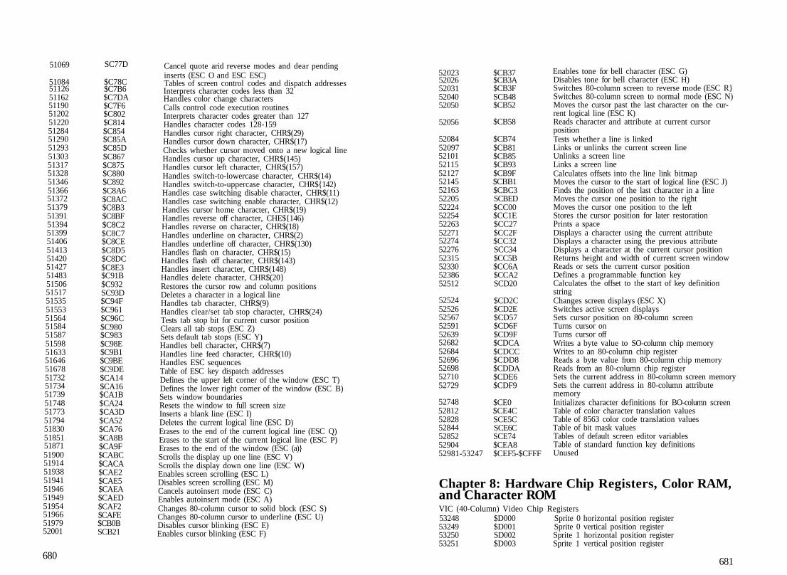
51069 SC77D
510845112651162511905120251220512845129051293513035131751328513465136651372513795139151394513995140651413514205142751483515065151751535515535156451584515875159851633516465167851732517345173951748517735179451830518515187151900519145193851941519465194951954519665197952001
$C78C$C7B6$C7DA$C7F6$C802$C814$C854$C85A$C85D$C867$C875$C880$C892$C8A6$C8AC$C8B3$C8BF$C8C2$C8C7$C8CE$C8D5$C8DC$C8E3$C91B$C932SC93D$C94F$C961$C96C$C980$C983$C98E$C9B1$C9BE$C9DE$CA14$CA16$CA1B$CA24$CA3D$CA52$CA76$CA8B$CA9F$CABC$CACA$CAE2$CAE5$CAEA$CAED$CAF2$CAFE$CB0BSCB21
Cancel quote arid reverse modes and dear pendinginserts (ESC O and ESC ESC)Tables of screen control codes and dispatch addressesInterprets character codes less than 32Handles color change charactersCalls control code execution routinesInterprets character codes greater than 127Handles character codes 128-159Handles cursor right character, CHR$(29)Handles cursor down character, CHR$(17)Checks whether cursor moved onto a new logical lineHandles cursor up character, CHR$(145)Handles cursor left character, CHR$(157)Handles switch-to-lowercase character, CHR$(14)Handles switch-to-uppercase character, CHR${142)Handles case switching disable character, CHR$(11)Handles case switching enable character, CHR$(12)Handles cursor home character, CHR$(19)Handles reverse off character, CHE${146)Handles reverse on character, CHR$(18)Handles underline on character, CHR$(2)Handles underline off character, CHR$(130)Handles flash on character, CHR$(15)Handles flash off character, CHR$(143)Handles insert character, CHR$(148)Handles delete character, CHR$(20}Restores the cursor row and column positionsDeletes a character in a logical lineHandles tab character, CHR$(9)Handles clear/set tab stop character, CHR$(24)Tests tab stop bit for current cursor positionClears all tab stops (ESC Z)Sets default tab stops (ESC Y)Handles bell character, CHR$(7)Handles line feed character, CHR$(10)Handles ESC sequencesTable of ESC key dispatch addressesDefines the upper left corner of the window (ESC T)Defines the lower right comer of the window (ESC B)Sets window boundariesResets the window to full screen sizeInserts a blank line (ESC I)Deletes the current logical line (ESC D)Erases to the end of the current logical line (ESC Q)Erases to the start of the current logical line (ESC P)Erases to the end of the window (ESC (a)}Scrolls the display up one line (ESC V)Scrolls the display down one line (ESC W)Enables screen scrolling (ESC L)Disables screen scrolling (ESC M)Cancels autoinsert mode (ESC C)Enables autoinsert mode (ESC A)Changes 80-column cursor to solid block (ESC S)Changes 80-column cursor to underline (ESC U)Disables cursor blinking (ESC E)Enables cursor blinking (ESC F)
680
5202352026520315204052050
52056
520845209752101521155212752145521635220552224522545226352271522745227652315523305238652512
5252452526525675259152639526825268452696526985271052729
52748528125282852844528525290452981-53247
$CB37$CB3A$CB3FSCB48$CB52
$CB58
$CB74$CB81$CB85$CB93$CB9F$CBB1$CBC3SCBED$CC00$CC1E$CC27$CC2F$CC32SCC34$CC5B$CC6A$CCA2SCD20
$CD2C$CD2E$CD57$CD6F$CD9F$CDCA$CDCC$CDD8$CDDA$CDE6$CDF9
$CE0$CE4CSCE5CSCE6CSCE74$CEA8$CEF5-$CFFF
Enables tone for bell character (ESC G)Disables tone for bell character (ESC H)Switches 80-column screen to reverse mode (ESC R}Switches 80-column screen to normal mode (ESC N)Moves the cursor past the last character on the cur-rent logical line (ESC K)Reads character and attribute at current cursorpositionTests whether a line is linkedLinks or unlinks the current screen lineUnlinks a screen lineLinks a screen lineCalculates offsets into the line link bitmapMoves the cursor to the start of logical line (ESC J)Finds the position of the last character in a lineMoves the cursor one position to the rightMoves the cursor one position to the leftStores the cursor position for later restorationPrints a spaceDisplays a character using the current attributeDisplays a character using the previous attributeDisplays a character at the current cursor positionReturns height and width of current screen windowReads or sets the current cursor positionDefines a programmable function keyCalculates the offset to the start of key definitionstringChanges screen displays (ESC X)Switches active screen displaysSets cursor position on 80-column screenTurns cursor onTurns cursor offWrites a byte value to SO-column chip memoryWrites to an 80-column chip registerReads a byte value from 80-column chip memoryReads from an 80-column chip registerSets the current address in 80-column screen memorySets the current address in 80-column attributememoryInitializes character definitions for BO-column screenTable of color character translation valuesTable of 8563 color code translation valuesTable of bit mask valuesTables of default screen editor variablesTable of standard function key definitionsUnused
Chapter 8: Hardware Chip Registers, Color RAM,and Character ROMVIC (40-Column) Video Chip Registers53248 $D000 Sprite 0 horizontal position register53249 $D001 Sprite 0 vertical position register53250 SD002 Sprite 1 horizontal position register53251 $D003 Sprite 1 vertical position register
681

532525325353254532555325653257532585325953260532615326253263532645326553266532675326853269532705327153272532735327453275532765327753278532795328053281532S25328353284532855328653287532885328953290532915329253293532945329553296
$D004$D005$D006$D007$D008$D009$D00A$D00B$D00C$D00D$D00E$D00F$D010SD011$D012$D013$D014$D015$D016$D017$D018$D019$D01A$D018$D01C$D01DSD01E$D01F$D020$D021$D022$D023$D024$D025$D026$D027$D028$D029$D02A$D02BSD02C$D02D$D02ESD02F$D030
SID (Sound Interface I542725427354274542755427654277542785427954280
$D400$D401$D402$D403SD404$D405$D406$D407$D408
Sprite 2 horizontal position registerSprite 2 vertical position registerSprite 3 horizontal position registerSprite 3 vertical position registerSprite 4 horizontal position registerSprite 4 vertical position registerSprite 5 horizontal position registerSprite 5 vertical position registerSprite 6 horizontal position registerSprite 6 vertical position registerSprite 7 horizontal position registerSprite 7 vertical position registerSprites 0-7 horizontal position (most significant bits)Control/vertical fine scrolling registerRaster scan line registerLight pen horizontal positionlight pen vertical positionSprite enable registerControl /horizontal fine scrolling registerSprite vertical expansion registerMemory control registerInterrupt flag registerInterrupt mask registerSprite-to-foreground priority registerSprite multicolor mode registerSprite horizontal expansion registerSprite-to-sprite collision registerSprite-to-foreground collision registerBorder color registerBackground color (source 0) registerBackground color source 1 registerBackground color source 2 registerBackground color source 3 registerSprite multicolor source 0 registerSprite multicolor source 1 registerSprite 0 color registerSprite 1 color registerSprite 2 color registerSprite 3 color registerSprite 4 color registerSprite 5 color registerSprite 6 color registerSprite 7 color registerExtended keyboard scan registerProcessor dock rate control register
Device) Chip RegistersFrequency register for voice 1 (low byte)Frequency register for voice 1 (high byte)Pulsewidth for voice 1 (low byte)Pulse width for voice 1 (high byte)Control register for voice 1Attack/decay register for voice 1Sustain/release register for voice 1Frequency register for voice 2 (low byte)Frequency register for voice 2 (high byte)
5428154282542835428454285542865428754288542895429054291542925429354294542955429654297542985429954300
545285452954530545315453254533545345453554536545375453854539
VDC5478454785
$D409$D40AJD40B$D40C$D40D$D40E$D40F$D410$D411$D412$D413$D414$D415$D416$D417$D418$D419$D41A$D41B$D41C
$D500$D501$D502$D503$D504$D505$D506$D507$D508$D509$D50A$D50B
(80-column) Video$D600$D601
Pulsewidth for voice 2 (low byte)Pulsewidth for voice 2 (high byte)Control register for voice 2Attack/decay register for voice 2Sustain/release register for voice 2Frequency register for voice 3 (low byte)Frequency register for voice 3 (high byte)Pulsewidth for voice 3 (low byte)Fulsewidth for voice 3 (high byte)Control register for voice 3Attack/decay register for voice 3Sustain/release register for voice 3Filter cutoff frequency (low byte)Filter cutoff frequency (high byte)Resonance/filter control registerVolume/filter mode registerPotentiometer 0 readingPotentiometer 1 readingVoice 3 oscillator outputVoice 3 envelope generator outputMMU (Memory Management Unit) Chip RegistersConfiguration registerPreconfiguration register APreconfiguration register BPreconfiguration register CPreconfiguration register DMode configuration registerRAM configuration registerPage 0 page pointerPage 0 block pointerPage 1 page pointerPage 1 block pointerMMU version register
Chip External Registers
VDC address/status registerVDC data register
682.
VDC Chip Internal Registers
2 $023 $03i $045 $056 $067 $078 $089 $0910 $0A11 SOB12 $0C13 SOD14 $0E15 $0F16 $1017 $1118 $12
Total number of horizontal character positionsNumber of visible horizontal character positionsHorizontal sync positionHorizontal and vertical sync widthTotal number of screen rowsVertical fine adjustmentNumber of visible screen rowsVertical sync positionInterlace mode control registerNumber of scan lines per characterCursor mode controlEnding scan line for cursorScreen memory starting address (high byte)Screen memory starting address (low byte)Cursor position address (high byte)Cursor position address (low byte)Light pen vertical positionLight pen horizontal positionCurrent memory address (high byte)
683

1920212223242526272$293031323334
as36
55296CIA (Complex56320563215632256323563245632556326563275632856329563305633156332563335633456335
CIA (Complex5657656577565785657956580565815658256583565845658556586565875658856589565905659156832-5708757088-57343
$13$14$15$16$17$18$19$1A$1B$1C$1D$1E$1F$20$21$22$23S24
$D800Interface Ada]$DC00$DC01SDC02SDC03$DC04$DC05$DC06$DC07$DC08$DC09$DC0A$DC0B$DC0CSDCOD$DC0E$DC0F
Interface Ada]$DD00$DD01SDDO2$DD03$DD04$DD05$DD06$DD07$DD08$DD09$DD0A$DD0B$DD0C$DD0D$DD0E$DD0F$DE00-$DEFF$DF00-$DFFF
Current memory address {low byte)Attribute memory starting address (high byte)Attribute memory starting address (low byte)Character horizontal size control registerCharacter vertical size control registerVertical smooth scrolling and control registerHorizontal smooth scrolling and control registerForeground/background color registerAddress increment per rowCharacter set address and memory type registerUnderline scan line position registerNumber of bytes for block write or copyMemory read/write registerBlock copy source address (high byte)Block copy source address (low byte)Beginning position for horizontal blankingEnding position for horizontal blankingNumber of memory refresh cycles per scan line
VIC color memory (two blocks)Adapater) Chip #1
Port A data I/O registerPort B data I/O registerPort A data direction registerPort B data direction registerTimer A latch/counter (low byte)Timer A latch/counter (high byte)Timer B latch/counter (low byte)Timer B latch/counter (high byte)Time-of-day dock (1/10 seconds)Time-of-day clock (seconds)Time-of-day Hock (minutes)Time-of-day clock (hours)Serial data registerInterrupt control registerControl register AControl register B
Port A data I/O registerPort B data I/O registerPort A data direction registerFort B data direction registerTimer A latch/counter (low byte)Timer A latch/counter (high byte)Timer B latch/counter (low byte)Timer B latch/counter (high byte)Time-of-day clock (1/10 seconds)Time-of-day clock (seconds)Time-of-day clock (minutes)Time-of-day clock (hours)Serial data registerInterrupt control registerControl register AControl register BI/O Expansion Slot #1I/O Expansion Slot #2
684
KEC (RAM Expansion Con in5708857089570905709157092570935709457095570965709757098
53248-57343
Chapter573445741957430574355745957491575495760957820578405789257922
57931579635805258055581045817158174582525843058578585835859258601586275864558662586935870258711587205872958739
58783
5881258819
SDF00$DF01$DF02$DF03$DF04$DF05$DF06$DF07$DF08$DF09$DF0A
$D000-$DFFF
9: Kerna$EO00$E04B$E056$E05BE073$E093$E0CD$E109$E1DC$E1FO$E224$E242
$E24B$E26B$E2C4$E2C7$E2FS$E33B$E33E$E38C$E43E$E4D2$E4D7$E4E0$E4E9$E503$E515$E526$E545$E54E$E557$E560$E569$E573
$E59F
$E5BC$E5C3
Controller) Chip RegistersStatus registerCommand registerSystem RAM base address (low byte)System RAM base address (high byte)Expansion RAM base address (low byte)Expansion RAM base address (high byte)Expansion RAM bankCount of bytes to transfer (low byte)Count of bytes to transfer (high byte)Interrupt mask registerAddress control register
Character pattern ROM (bank 14)
Performs power-on/reset sequenceTable of default MMU register settingsRestores Kemal indirect vectors to their default valuesLoads or copies Kernal indirect vector valuesTable of default Kernal indirect vector valuesInitializes zero page and Kemal pointersInitializes all RAM-resident Kernal routinesInitializes I/O chip registersInitializes 80-column video chip registersInitializes or jumps through the soft reset vectorInitializes the soft reset vectorChecks for the presence of 64 cartridges or 128 func-tion ROMsSwitches the system into 64 modeLogs 128 function ROMsInitialization test patternTable of default VIC chip register valuesTable of default 8563 chip register valuesSends TALK command to a serial deviceSends LISTEN command to a serial deviceSends buffered byte to a serial deviceReads a byte from a serial deviceSends secondary address after LISTENAllows the serial bus ATN output line to go highSends secondary address after TALKPerforms talk-listen turnaroundSends a byte to a serial deviceSends UNTALK command to a serial deviceSends UNLISTEN command to a serial deviceAllows serial bus CLK output line to go highFulls serial bus CLK output line lowAllows serial bus DATA output line to go highPulls serial bus DATA output line lowReads the serial bus DATA and CLK input linesDisables IRQ interrupts and standardizes timing dur-ing I/O operationsReenables interrupts and restores clock mode afterI/O operationsPerforms fast serial turnaroundSets serial device for fast serial input
685

58838588755887958907589485895459007590225903759058590745909259103591775922B592855934259372
5939759472
594925951259561596005967359776597835980259838598485987159881598905989959925599285994260047
60065601396075360762607776081660974
61015
6107761083611046U1161121
SE5D6$E5FB$E5FF$E61B$E644$E64A$E67F$E68E$E69D$E6B2$E6C2SE6D4$E6DF$E729$E75C$E795$E7CE$E7EC
$E805$E850
$E864$E878$E8A9$E8D0$E919$E980$E987$E99ASE9BE$E9C8$E9DF$E9E9$E9F2$E9FB$EA15$EA18$EA26$EA8F
$EAA1$EAEB$ED51$ED5A$ED69$ED90$EE2E
$EE57
$EE95$EE9B$EEB0$EEB7$EECI
Sets serial device for fast serial outputSets serial device for fast serial input or outputPrepares next bit for RS-232 transmissionPrepares parity and stop bitsPrepares to send a stop bitPrepares to transmit next byteSets CIA interrupt register and RS-232 activity flagComputes bit count for the RS-232 operationProcesses received bitsTests for stop bitPrepares to receive next byteTests for start bitStores received character in buffer and checks parityHandles CKOUT for RS-232 deviceHandles BSOUT for RS-232 deviceHandles CHKIN for RS-232 deviceHandles GETIN for RS-232 deviceDisables RS-232 activity during tape or serial busoperationsHandles NMI interrupts for RS-232Table of baud rate timing constants for NTSCsystemsTable of baud rate timing constants for PAL systemsReads a bit from RS-232 deviceInitiates reception of RS-232 byteReads next header block from tapeWrites a header block to tapeLoads and tests cassette buffer addressSets buffer address as block addressSearches for a specified headerChecks for cassette buffer filled or emptiedRequests PLAY button if necessaryChecks tape buttonsRequests RECORD and PLAY buttons if necessaryReads next header or data block from tapeReads or verifies a block from tapeWrites a header or data block to tapeWrites a block to tapeInitiates tape I/O operationChecks for RUN/STOP keypress during tapeoperationsSets timer A to check FLAG interruptsReads or verifies a block of data from tapeLoads working pointer with starting addressInitializes tape variables between each byteInitiates writing of a tape half-dipoieWrites a block of data to tapeWrites a leader to tape and prepares to write a datablockRestores IRQ vector and operating modes after tapeoperationEnds tape write interruptsLoads IIRQ vector for tape operationTurns cassette motor offTests whether ending address has been reachedIncrements the working pointer
686
611286113661163611906122461276612876130561332613676137361430615046161661643617026173561772618056183261S656190361924619546197061986619906201362053620756224662369624426261662630
62642
626506266]62723627356277162782628176287862901629086292062968
6303763070630776308663100
$EEC8$EED0$EEEB$EF06$EF28$EF5C$EF67$EF79$EF94$EFB7SEFBD$EFF6JF040$F0B0$F0CB$F106$F127$F14CSF16D$F188$F1A9$F1CF$F1E4$F202$F212$F222$F226$F23D$F265F276$F326$F3A1$F3EA$F496$F4A6
SF4B2
SF4BASF4C5$F503SF50F$F533SF53E$F561SF59E$F5B5$F5BC$F5C8$F5F8
$F63D$F65E$F665$F66E$F67C
Handles FLAG interrupts for tapeControls tape motor interlockRetrieves a byte from the current input deviceAccepts a byte from the current input deviceAccepts a byte from tapeAccepts a byte from a serial deviceAccepts a byte from RS-232Sends a byte to the current output deviceSends a byte to tapeSends a byte to the RS-232 portOpens a logical file to a specified deviceOpens a file for input or output to tapeOpens a file for RS-232 communicationsSets up CIA #2 ports for RS-232 communicationsOpens a file for serial bus communicationsSets the current input file for GETIN and BASINPrepares a serial device file for inputSets the current output file for BSOUTPrepares a serial device file for outputCloses a specified logical fileCloses a tape fileCloses a file on a serial deviceRemoves an entry from the logical file tablesChecks whether a file is already openLoads parameters for a logical SleClears file table entriesResets default I/O channelsCloses all open files for a specified serial deviceLoads or verifies a program file from disk or tapeLoads or verifies a file from a serial deviceLoads or verifies a program file from tapeAttempts to set up fast serial load or verifyLoads or verifies a file using fast serial burst modeHandles read error during burst mode load/verifyStops burst mode load/verify if RUN/STOP keypressedAborts burst mode load/verify if maximum addressexceededReads a byte using fast serial hardwareLoads or verifies a block of data using burst modeToggles state of serial bus CLK lineDisplays SEARCHING FOR messageDisplays LOADING or VERIFYING messageSaves a block of memory to tape or diskSaves a block of memory to a serial deviceCloses a file on a serial deviceAborts LOAD or SAVE to serial deviceDisplays SAVING message and filenameSaves a block of memory to tapeUpdates jiffy timers and checks RUN/STOP keycolumnScans RUN/STOP key columnReads the software jiffy clockSets the software jiffy clockTests for a RUN/STOP keypressHandles Kemal I/O errors
687

631526326263281
63288
632956330063324633276333163346633616336663389633976340663420634236343363436634406345063459
63468
634726348863591
636326388363923639956400864023640646410164128
$F6B0$F71E$F731
SF738
$F73F$F744$F75C$F75F$F763$F772$F781$F?86$F79D$F7A5$F7AE$F7BC$F7BF$F7C9$F7CC$F7D0$F7DA$F7E3
$F7EC
$F7F0$F800$F867
SF890$F98B$F9B3$F9FB$FA08$FA17$FA40$FA65$FA80
M M U (Memory Management652806528165282652836528465285
653036533165341653516535465357653606536365366
5FF00$FF01$FF02$FF03$FF04$FF05
$FF17$FF33SFF3D$FF47$FF4A$FF4D$FF50$FF53SFF56
Table of Kernal control messagesHandles Kemal control messagesSets the length and address of filename for I/OoperationsSets logical file number, device number, and second-ary address for I/O operationsSets data and filename banks for I/O operationsReads the tape/serial or RS-232 status byteSets the Kemal message control flagSets the IEEE timeout flagSets or reads the system's top-of-memory pointerSets or reads the system's bottom-of-memory pointerReturns base address of I/O blockChecks whether a secondary address value is usedChecks whether a logical file number value is usedPerforms a DMA operationRetrieves a character from the current filenameWrites a byte value to memoryWrites a byte value to memoryReads a byte value from memoryReads a byte value from memoryRetrieves a character from any bankStores the accumulator contents in any bankCompares the accumulator contents with a valuefrom any bankTranslates a bank number into an MMU registersettingTable of MMU register settings for standard banksCode for Kemal RAM-based subroutinesInitializes function ROMs and attempts to boot a diskin the default driveAttempts to boot a diskResets the disk driveLoads additional b< Jt sectorsConverts a byte value into two ASCII digitsTable of disk commands for bootingHandles PRIMM (print immediate) functionHandles NMI interruptsHandles IRQ interruptsStandard keyboard decoding tables
Unit) Chip RegistersConfiguration registerLoad configuration register ALoad configuration register BLoad configuration register CLoad configuration register DJump to NMI handler routine
Jump to IRQ or BRK handler routineCommon exit routine for all interrupt routinesJump to reset handler routineEntry point for the Kemal SPIIsLSPOUT routineEntry point for the Kemal CLOSF_J\LL routineEntry point for the Kemal C64—MODE routineEntry point for the Kema! DMA_CALL routineEntry point for the Kemal BOOT_CALL routineEntry point for the Kemal PHOENIX routine
688
6536965372653756537865381653846538765390653936539665399654026540565409654126541565418654216542465427654306543365436654396544265445654486545165454654576546065463654666546965472654756547865481654846548765490654936549665499655026550565508655116551465? 17655206552365528655306553265534
$FF59$FF5C$FF5F$FF62$FF65$FF68$FF6B$FF6E$FF71$FF74$FF77$FF7A$FF7D$FF81$FF84$FF87$FF8ASFF8D$FF90$FF93$FF96$FF99$FF9C$FF9F$FFA2$FFA5$FFA8$FFAB$FFAE$FFB1$FFB4$FFB7$FFBA$FFBD$FFC0$EFC3$FFC6$FFC9$FFCC$FFCE$FFD2$FFD5$EFD8$FFDB$FFDE$FFE1$FFE4$FFE7$FFEA$FFED$FFF0$FFF3$FFF8$FFFASFFFC$IH1:
Entry point for the Kernal LKUPLA routineEntry point for the Kernal LKUTSA routineCalls the screen editor SWAPPER routineCalls the screen editor INIT80 routineCalls the screen editor KEYSET routineEntry point for the Kemal JSETBNK routineEntry point for the Kemal GETCFG routineEntry point for the Kernal JSRFAR routineEntry point for trie Kemal JMPFAR routineEntry point for the Kemal INDFET calling routineEntry point for the Kemal INDSTA calling routineEntry point for the Kemal INTJCMP calling routineEntry point for the Kemal PRIMM routineCalls the screen editor CINT routineEntry point for the Kernal IOINIT routineEntry point for the Kemal RAMTAS routineEntry point for the Kemal RESTOR routineEntry point for the Kemal VECTOR routineEntry point for the Kemal SETMSG routineEntry point for the Kemal SECOND routineEntry point for the Kemal TKSA routineEntry point for the Kemal MEMTOP routineEntry point for the Kernal MEMBOT routineCalls the screen editor SCNKEY routineEntry point for the Kemal SETTMO routineEntry point for the Kemal ACPTR at routineEntry point for the Kemal C1OUT routineEntry point for the Kemal UNTLK routineEntry point for the Kemal UNLSN routineEntry point for the Kemal L1STN routineEntry point for the Kernal TALK routineEntry point for the Kemal READSS routineEntry point for the Kemal SETLFS routineEntry point for the Kemal SETNAM routineEntry point for the Kemal OPEN routineEntry point for the Kemal CLOSE routineEntry point for the Kemal CHKIN routineEntry point for the Kernal CKOUT routineEntry point for the Kemal CLRCH routineEntry point for the Kemal BASIN routineEntry point for the Kernal BSOUT routineEntry point for the Kemal LOAD routineEntry point for the Kemal SAVE routneEntry point for the Kemal SETT1M routineEntry point for the Kernal RDTIM routineEntry point for the Kernal STOP routineEntry point for the Kemal GETIN routineEntry point for the Kemal CLALL routineEntry point for the Kemal UDTIM routineCalls the screen editor SCRORG routineCalls the screen editor PLOT routineEntry point for the Kernal IOBASE routineSoft reset vector (bank 1)Processor NMI vectorProcessor reset vectorProcessor BRK/IRQ vector
689

Here's the complete guire to understanding the innerworkings of the Comrodore 128. Collected in this one
volume are the answe's to practically any questions youmight have about thy -vav +he Commodore 128 operates.
Moreover, the information presented here isn't just edu-cational—it has tremendous practical value as well. Increas-ing your understanding of how the computer operates putsyou more fully in control. Whether you program in BASIC ormachine language, or whether you are just starting out orare an expert programmer, you'll find that this book unlockssecrets of the 128 that will allow you to write more powerfuland more sophisticated programs. Inside you'll find:
• A complete reference to BASIC, the Kerndl, the screen edi-tor, even the machine language monitor. Not just a list ofaddresses, but detailed discussions of all the important ROMroutines.
« Thorough descriptions of all the video, sound, and Interfacechips—VIC, SID, VDC, MMU, CIA, and REC. Every register ofevery chip is explained in detail.
• A clear and straightforward explanation of how the 128'selaborate memory management system operates, and howyou can create your own custom memory configurations.
• Hundreds of suggestions and hints on how to take full ad-vantage of the 128's enhanced capabilities.
- Examples of ways you can modify and improve the per-formance of your computer, including how to add newstatements to BASIC and how to customize Kernal functions.
• Explanations of the bugs in BASIC and the Kernal, and howto avoid them.
If you've mastered the fundamentals of your 128 and areseeking to expand your knowledge of this powerful, versatilesystem. Mapping the Commodore 128 can be your guide, Ifyou're a veteran programmer who moved up to the 128after years of experience on an older Commodore model,this book will help you adapt your established techniques toyour new machine. For advanced programmers. Mappingthe Commodore 128 provides a wealth of ideas for excitingnew programming projects, Much of the information gath-ered here is available elsewhere only in bits and scraps, if atall. You'll want to keep a copy close at hand every time youturn on your 128,
ISBN 9-87455-060-2