mapping mechanism to enhance qos in ip...
TRANSCRIPT

Mapping Mechanism to Enhance QoS in IP Networks
by
Sriharsha Karamchati, Shatrunjay Rawat, Sudhir Yarram, Guru Prakash Ramaguru
in
The 32nd International Conference on Information Networking (ICOIN 2018)
Report No: IIIT/TR/2018/-1
Centre for Security, Theory and AlgorithmsInternational Institute of Information Technology
Hyderabad - 500 032, INDIAJanuary 2018

Mapping Mechanism to Enhance QoS in IPNetworks
Sriharsha KaramchatiCSTAR
IIIT HyderabadIndia
Email: [email protected]
Sudhir YarramCVIT
IIIT HyderabadIndia
Email: [email protected]
Shatrunjay RawatCSTAR
IIIT HyderabadIndia
Email: [email protected]
Guru Prakash RamaguruCVIT
IIIT HyderabadIndia
Email: [email protected]
Abstract—The purpose of this research is to explore thepossibilities and mechanisms to be followed in order to extendthe QoS in the backbone networks. This paper extends the ideasdiscussed in my previous paper: A Novel Architecture to EnhanceQuality of Service in IP Networks [1] explaining the consequencesof the proposal and building a model network. Simulated anSDN network using mininet and presented the packet capturesdepicting the extension of QoS outside the access networks.
Key words: Quality Of Service, Backbone Networks, Net-work Architecture
I. INTRODUCTION AND BACKGROUND
Quality of Service is used to measure service performancein computer networks. It is used to prioritize among differentapplications, users or data flows and perform resource reser-vation control mechanisms.The Service can be to a particularset of users, or a particular data flow or kind of packets. Thedifferentiation in the services can be in terms of packet loss,throughput, bit error rate, jitter, latency etc. It is particularlyimportant to transport traffic that has special requirementsor insufficient network capacity, for example, voice over IP(VoIP), IPTV,Online gaming. Most times, these real timemultimedia streaming applications require fixed bit rate andare delay sensitive.
Typical issues which arise while the packet travels fromorigin to destination are drops,throughput, latency, jitter anderrors.
In the current day internet, the bandwidth and resourcerequirement varies from application to application. With newapplications taking over the internet, video and audio callingover IP networks have become the most routinely used featuresof the applications. These features have necessities such ashigh bandwidth, for example skypes bandwidth requirementis as follows.
The table I provides the minimum download and uploadspeeds required, as well as the recommended speeds for bestperformance. If you are signed in to Skype but not making any
calls, Skype will use on average 0-4kbps. When you make acall, Skype will use on average between 24-128kbps 1.
Call type Minimum down-load/upload speed
Recommendeddownload/upload speed
Calling 30kbps / 30kbps 100kbps / 100kbpsVideo calling/Screen sharing
128kbps / 128kbps 300kbps / 300kbps
Videocalling(high-quality)
400kbps / 400kbps 500kbps / 500kbps
Videocalling(HD)
1.2Mbps / 1.2Mbps 1.5Mbps / 1.5Mbps
Group video(3people)
512kbps / 128kbps 2Mbps / 512kbps
Group video(5people)
2Mbps / 128kbps 4Mbps / 512kbps
Group video(7+people)
4Mbps / 128kbps 8Mbps / 512kbps
TABLE IDOWNLOAD / UPLOAD SPEEDS
II. ARCHITECTURE:
Real Time applications are fast growing in the internet.From the previous sections it is pretty evident that an improvedQoS is needed for a packet in these applications. This can bedone by
1) Enhancing the existing QoS by using better resources andrefined algorithms.
2) Exploring the extension of QoS into those areas where itwas not available previously.
The paper proposes an architectural solution to the secondapproach. . In general the QoS is provided within an accessnetwork because
1) QoS provider has knowledge about the network parame-ters.
1https://www.cable.co.uk/guides/what-broadband-speed-do-i-need-for-skype/
2) resources can be allocated in an structured manner basedon the priority of the packets.
3) The SLAs can be defined in a systematic manner betweenthe service provider and the customer.
The architectural solution presents a method to provide QoSacross the different access networks.A few infrastructurechanges will be needed for this implementation, as layer -3 devices have to be installed in order to mark the packetsin the backbone network.The possible methods and theirconsequences are also discussed.
A network consists of various access networks which arediverse in terms of QoS provisions. The packets traverse acrossdifferent access networks which have their own network con-ditions and QoS. These differences across the access networkscan be in terms of the protocols used for communication,bandwidth capacity of the link through which the packet hastraversed, the delays suffered by the packet and other servicesprovided to the packet.
Once the packet traverses beyond its access network, itenters into the backbone network. Since the packets in thebackbone network come from various access networks, theservices provided to each of the packets within its accessnetwork have to be taken into consideration in order to providethe QoS in the backbone network.. However, the ToS or DSCPbit is set in the packet for an access network, based on whichthe QoS provisions are made to the packet, there could be otherservices provided to the customer based on the availability ofresources in that particular access network.
Other than the ToS/DSCP bit which is set to the packetin its access network, there could be other parameters whichaffect the packets flow such as bandwidth, bit error rate,packet loss and packet delay variation.
Service providers and the customers:In the current day telecommunication market place, vari-
ous service providers and customers need SLAs [2]. Serviceproviders can be of three types, Network Service Provider(NSP), Internet Service Provider (ISP) and Application Ser-vice Provider (ASP). Consumers can also be of three typesindividual, organization or enterprise.
SLA Provisioning and SLA monitoring are the most im-portant processes in the network management layer. Networkservice can be of various kinds such as leased line service,IP-VPN service, xDSL services, Frame relay service, etc.
QoS Parameters represent the quality of service given to thecustomer. It should be easy for the customers to understandthe degree of assurance of the service provided. Generic QoSparameters which are required in the network service areavailability, delivery, latency, bandwidth, MTBF (Mean TimeBetween Failure) and MTRS (Mean Time to Restore Service).
The first four parameters could be mapped to the NetworkPerformance Metrics(NPMs) as they are technology specificand could be easily measured, whereas MTBF and MTRScannot be mapped to NPMs.
NPMs can be categorized into four types, which are
Fig. 1. QOS Parameter
1) Availability :• Connectivity : the physical connectivity between the
network elements• Functionality : proper functioning of the network ele-
ments in the network management layer2) Loss3) Delay4) Utilization
Fig. 2. NPMs
A. Mapping between QoS parameters and NPMs
Mapping between QoS parameters and NPMs can be of twotypes :- measurement mapping and evaluation mapping.
In the figure 3, MTBF and MTRS are the QoS parameterswhich cannot be directly measured from the NPMs.hereforethey are computed by the service providers when there is aviolation of NPMs.
Evaluation mapping is used to verify QoS parameters fromthe measured NPM values. For example, the availability qosparameter relates to connectivity and functionality in thenetwork service. Therefore availability can be evaluated basedon the downtime of the network elements.
The measurement and evaluation mappings have to begeneralized, as the QoS parameters may vary depending ondifferent NPMs, with various service providers and customers.

Fig. 3. Measurement mapping
Fig. 4. Evaluation Mapping
Generic function of mapping between QoS parameters andNPMs can be defined using mathematical sets and functions.
Let there be three sets Q, N and E.• Q represents set of QoS parameters• N represents set of NPMs• E represents of set of evaluation functions.
Fig. 5. Function
Set 2N is the power set of N. Measurement mapping m(x)can be defined as the relationship between set 2N and set Q.Evaluation mapping n(x) can be defined as the relationshipbetween set 2N and set E.
B. Introduction of QoS aware routers
In general, a sub network does not have the information suchas resource allocation or routing information of the other subnetwork. Therefore provisioning of QoS is restricted within theaccess network. Hence this paper proposes a QoS aware routerto eliminate the restriction by extending the services providedto the packet into the backbone network. It is typically a layer-3 device, but a layer-2 device which can modify QoS relatedfields such as ToS/DSCP of a packet can also be used. TheQoS bit of the packet in the backbone network has to mapped
to a particular value based on which the further services areprovided.
This mapping can be designed in various possible ways,1) A control message is sent to these QoS aware routers
which change the QoS of the packet according to therequirement of that traffic.
2) The packet itself contains a value according to which theQoS is mapped.The optional fields in the packet can beused to store these values.
The QoS aware routers(QA) may upgrade or downgrade thepriority of the packet as per the requirement. The placementof such routers is a key criteria as it involves computation.In general, the backbone network contains switches and theprocessing involved is very less, in order to keep transmissionfast in a backbone network.
C. Example of traffic from one network to another:
Consider a packet traversing from a network A into anothernetwork B. In order to accommodate the QoS provision whichwas assured for the packet, QoS has to be provided in networkA as well as in the network B.
But the network A and network B could be different atvarious levels such as protocol followed, resources availableetc. Hence we need a mapping between the QoS parametersfrom one network to another.
For example, in a particular network the QoS is guaranteedat the Bit Error Rate level. But when the packet traverses intoanother network, it can be mapped to packet loss and canassure QoS based on the packet loss.
For example, in a particular network the QoS is guaranteedat the Bit Error Rate level. When the packet traverses intoanother network, which provides services to the packet interms of packet loss, the QoS assurance has to be givenin terms of packet loss. Hence there should be a mappingbetween the QoS provisioning in terms of Bit Error Rate andpacket loss in order to assure QoS to a packet throughout itstraversal.
D. IP vs ATM
In an IP network, there is a priority bit set in the packet andthere is no parameter specification such as bandwidth Whereasin an ATM network minimum or maximum bandwidth wouldbe specified. Suppose if an ATM network is connected to anIP network, in general IP is translated to best effort of ATM.But when we carry out QoS mapping, additional services canbe guaranteed. The services guaranteed are supported by theapplication layer and not the IP layer. Since there is no end toend ATM network, it is rarely used as the edge network andmostly as a backbone network. If IPv6 packet is mapped toan ATM network, it would be easier for ATM to handle andmap as the ATM has more services compared to that of IPv6.
E. Issues architecture is trying to address:
The research proposes architecture which tries to solve theQoS provisioning issues when a packet traverses from onenetwork to another. The QoS can be mapped and carried across

networks that have different protocol etc. Though both thenetworks provide QoS and have the required infrastructure,the way QoS is provided might not be compatible and thearchitecture proposed provides the mapping which could beused in those scenarios.
As we explore the possibility of introduction of QoS intothe backbone network, there could be multiple constraints asthe installation of QoS aware routers requires change in theexisting infrastructure.
F. When do we need this architecture
This architecture can be provided based on the SLA be-tween the service provider and the customer. Since it involvesadditional computation and resources, we need to identifythe situations and scenarios where the architecture would beneeded and to what extent it would be needed.
The mapping algorithm varies across the networks in whichthe packet traversal takes place. If a packet traverses intothe network B from network A and if both A and B havesimilar QoS provisioning, the mapping algorithm has no roleto perform. The similarity factor between the networks can bedecided based on the QoS related network parameters. Theevaluation of similarity factor can be left for future research.
There could be two cases possible a)when a packet does notrequire the mapping and b)when the customer is not subscribedto the mapping service. In case (b), the packet can bypass theQoS aware routers and follow best effort path.
Whereas in case (a), lets assume the packet traverses fromnetwork a1 -¿ a2 and then to a4. Here a1 and a2 are of similarQoS requirements and hence there is no need of mapping. Butwhen the packet goes into the a4 network, it needs mapping.The QoS requirements ,based on which the similarity of thenetworks is defined, are not specific to the packet, but ratherto the full network architecture it traverses in.
The QoS requirement in a particular network can either beinserted into the packet at the gateway or the edge devices, if anetwork does not want to expose the internal implementationdetails to the backbone network. The treatment can vary fromconnection to connection or session to session, rather than ata packet level. For example, in an ATM network the mappingcan be based on the connection id, and similar mappingalgorithm is applicable for all the packets belonging to thatparticular connection, thereby reducing the overhead of reevaluating the mapping parameters for each of the packets.
G. Issues with introduction of such an architecture
Security will be of major concern since the treatment of thepackets is based on what information is put into the packet atthe edge devices. The information put into the packet should beauthenticated, verified and should comply with the SLA. Forexample, a malicious edge router might upgrade the packetpriority to a very high value, hence the backbone providesthe highest priority to the packet though it is not defined inthe SLA and might cause degradation of services to the otherflows.
There could be multiple other drawbacks of the architectureproposed, the prime one being requirement of change in thenetwork infrastructure. Since the QoS aware routers have tobe installed at particular places in a network, the complete net-work topology which has to be taken under consideration, hasto be clearly defined. The additional overhead of prioritizingthe flows after considering the network parameters might causedelays and can affect the performance. Hence the optimizationof the mapping algorithms has a significant scope for research.
There could also be a case where the QoS of the packetgets degraded due to the unavailability of resources or QoSprovisioning in the backbone network. Since there couldbe a compromise of QoS in the access networks assumingupgradation of QoS in the backbone network/
There could be a case where the QoS of a packet in theaccess network is compromised assuming the upgradation ofthe QoS in the backbone network. But if the backbone networkfails to upgrade the QoS due to unavailability of resources, theoverall QoS of the packet is degraded.Hence the availabilityand allocation of resources has to be known in prior in a largescale which could affect the scalability of such an architecture.
To address some of these issues, software defined net-works(SDN) would play a key role. SDN technology isan approach to computer networking which allows networkadministrators to programmatically initialize, control, changeand manage network behaviour through open interfaces andoperate at a higher abstraction level. It was introduced toaddress static nature of traditional networks which do not sup-port the dynamic and scalable computation. This is achievedthrough decoupling of SDN controller or control plane (whichmake decisions regarding the propagation of traffic) from dataplane (which constitutes of systems that forward traffic to therespective destinations).
Therefore in case of an SDN, there would not be significantinfrastructure changes.
Few modules have to be installed into the SDN controllerwhich maps the packets based on the QoS provided for thepacket or flow in its access network.
It also considers the QoS related network performancemetrics of that access network and assigns the QoS bits (ToSor DSCP).
According to these bits the treatment of those respectivepackets is provided in the backbone network.
Modifications to the flow entries have to be made based onthe mapping algorithm.
The model topology, the working of the proposed archi-tecture and the mechanism is implemented on mininet and isexplained in detail in the next section.
III. MAPPING AND SIMULATION
In order to provide QoS to a packet when it traverses fromone network to another, various parameters of the packet aswell as the networks through which the packet traverses has tobe taken into consideration. These include ToS of the packetin the source network,the protocols followed in the networks,control flags of the packet etc. Bandwidth and bit error rate

would also be an important criteria to understand the QoSprovided in a network.
Hence the proposed mapping box assigns a QoS value tothe packet based on these parameters. This value is used toprovide the services to the packet in the backbone network.The flow of the packets would be as shown in figure 6
Fig. 6. Mapping Flow chart
The mapping box can be treated like a black box whichtakes the set of packets from diverse networks and their QoSrelated parameters as input. It then assigns the QoS valueaccording to the parameters and outputs the packets intodifferent streams. Based on the streams through which thepacket traverses, QoS is provided to the packet in the backbonenetwork.
When the desired QoS is not provided to the packet inits access network, a flag is included along with the otherparameters which act as input to the mapping box. Theflag indicates if the desired QoS is delivered to the packetin its access network. Based on the flag, the mapping isperformed to upgrade or downgrade the packets QoS in thebackbone network to ensure the expected delivery of QoS tothat particular packet.
Our router would have very similar components comparedto a DiffServ router, but the criteria of classification wouldalso include network parameters such as Bandwidth and Biterror rate in order to differentiate the network.
The simulation run resulted in a model network whichillustrates the functioning of the proposed architecture and theQoS aware router.
A. SIMULATION
The network topology for simulation consists of one QoSaware router to which the three gateway routers of three accessnetworks(A1,A2 and A3) are connected. This QoS awarerouter is again connected to the router E.
The topology is simulated to model a network in which thepackets traverse from the access network into the backbonenetwork. The packets are provided with QoS inside the accessnetworks and the proposed architecture extends the servicesinto the backbone network.
In our simulation, let’s assume the access networks to con-sist of a host(Hx) and another local network (Nx). The packetshave an existing QoS provided inside each of the accessnetworks. The packets traverse into the backbone networkthrough the edge routers.
The QoS will be assigned to each of the packets at theQoS aware router. The assignment is based on the QoS of thepacket in its access network and other network performancemetrics.
The packets further traverse to router E with the assignedQoS bit. The activity at the router E explains the behaviour ofthe packet as per their assigned QoS.
Consider the below figure 7
Fig. 7. Simulation
In our simulation, the packet traversing from the accessnetwork A, through the Router-A has a QoS bit value of 1.And the packets from the network B and C have their QoSbit values as 3 and 5 respectively.
When the packets arrive at the Router D, the QoS bits wouldbe modified to QoS-A , QoS-B and QoS-C respectively.
QoS-A is the output of a calculation made based on thenetwork parameters of A which are related to QoS and existingQoS bit of the packet.There could be other parameters likeSLA included in the computation as well.
The SLA is an important consideration during the compu-tation as the services are provided to the user according to theSLA. Hence factors related to the SLA influence the QoS-Ato a large extent.
There could be a possible scenario where the guaranteedQoS in the access network is compromised for lack of re-sources. In that case, the QoS has to be upgraded in thebackbone network in order to compensate for the loss inservices in the access network. To implement such a service,flag has to be set when there is a variation in the servicesprovided to the packet in the access network. so that it can beupgraded or degraded in the backbone network accordingly.The flag can also represent to what extent the service levelhas been varied.
Therefore the QoS-A can be written as a function ofSLA factor, Existing QoS in the access network, networkparameters and the flag.
QoS-A = f(SLA,FLAG,QoSa,NPM).
B. Experimental Results
The simulation of the above mentioned mapping is carriedout in an SDN environment using mininet. The connection forthe simulation is mentioned as below.
h1r1 is connected to A. h1r2 is connected to B. h1r3 isconnected to C. bh1 is connected to E.
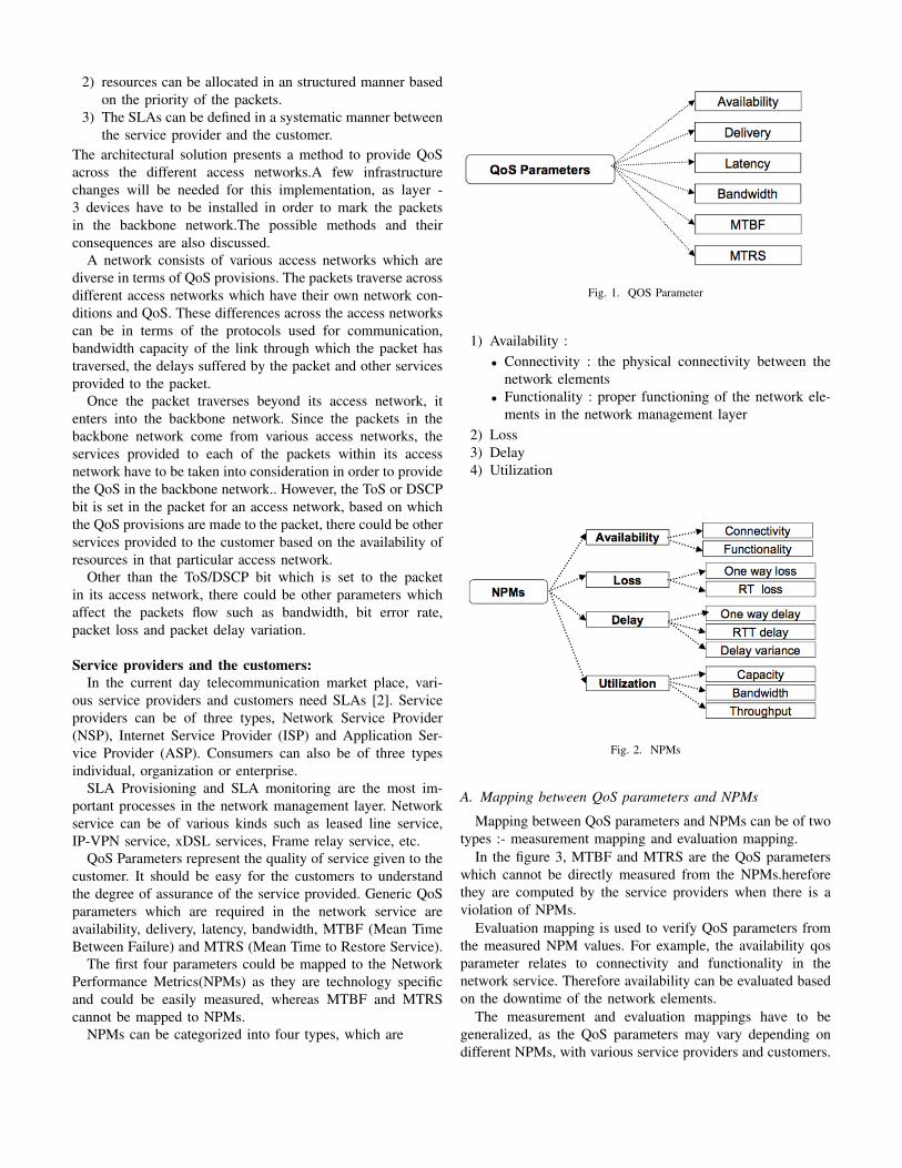
A,B and C are in turn connected to D, which is connectedto E. A controller is connected to each of these entities. In anSDN, all the devices are termed as switches.
Fig. 8. Experimental Design
The packets which traverse from Switch A have the ToSbit value set as 4, packets from Switch B have ToS as 8 andthose from Switch C as 10. As per our proposal, switch Dis the special router which maps the QoS bits based on thesource network. When the packets traverse from the switchD to switch E, the packets whose ToS bit is 4 is mapped to1, packets having ToS bit 8 is mapped to 2 and the packetshaving ToS bit 10 are mapped to 3.
For simplicity , we assume the mapping is one to onebetween the ToS from A,B and C and also for those thattraverse out of D. These packets are put into 3 different queuesbased on the ToS bit at E. There would be variations in theservices provided to each of the queues at E such as bandwidthcapacity of the queue etc.
The packets were captures using wireshark during theirdifferent phases of the traversal. The QoS bit of the packetsduring those phases is presented below.
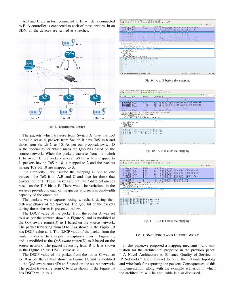
The DSCP value of the packet from the router A was setto 4 as per the capture shown in Figure 9, and is modified atthe QoS aware router(D) to 1 based on the source network.The packet traversing from D to E as shown in the Figure 10has DSCP value as 1. The DSCP value of the packet from therouter B was set to 8 as per the capture shown in Figure 11,and is modified at the QoS aware router(D) to 2 based on thesource network. The packet traversing from B to E as shownin the Figure 12 has DSCP value as 2.
The DSCP value of the packet from the router C was setto 10 as per the capture shown in Figure 13, and is modifiedat the QoS aware router(D) to 3 based on the source network.The packet traversing from C to E as shown in the Figure 14has DSCP value as 3.
Fig. 9. A to E before the mapping
Fig. 10. A to E after the mapping
Fig. 11. B to E before the mapping :
IV. CONCLUSION AND FUTURE WORK
In this paper,we proposed a mapping mechanism and sim-ulation for the architecture proposed in the previous paper:“ A Novel Architecture to Enhance Quality of Service inIP Networks.” Used mininet to build the network topologyand wireshark for capturing the packets. Consequences of thisimplementation, along with the example scenarios in whichthe architecture will be applicable is also discussed.

Fig. 12. B to E after the mapping:
Fig. 13. C to E before the mapping
Fig. 14. C to E after the mapping
A. Future Work
The implementation of the proposed architecture requiressignificant changes in the infrastructure.Hence all possibleways to reduce computation and other infrastructural changesrequired have to be explored.The scenarios in which theproposed architecture can be applied have to be explored.
The algorithm used in the mapping box has scope for signif-icant research. The impact factor for each of the parameterstaken into consideration for classification can be derived byconducting experiments.
Since the usage of software defined networks(SDN) hasincreased in the recent times, the implementation of theproposed mechanism in the SDN can be explored in future.The simulation presented in the paper can be used as a startpoint.
REFERENCES
[1] S. Karamchati and S. Rawat and V. Varma , A novel architecture toenhance Quality of Service in IP networks, 2017 International Conferenceon Information Networking (ICOIN).
[2] Hyo-Jin Lee and Myung-Sup Kim and James W. Hong and Gil-HaengLee, QoS Parameters to Network Performance Metrics Mapping for SLAMonitoring, 2013