manufacturing technology i laboratory … technology lab...lathe tool dynamometer 3. cutting tool 4....
TRANSCRIPT

MANUFACTURING TECHNOLOGY – I
LABORATORY MANUAL
MECHANICAL ENGINEERING DEPARTMENT
(ISO 9001:2008 Certified)
MES COLLEGE OF ENGINEERING, KUTTIPPURAM
Manufacturing
Technology –I
Laboratory Manual
MECHANICAL ENGINEERING DEPARTMENT
Revision Date Prepared by Approved by
Name Designation Signature Name Designation Signature
Rev1.0 Dr.Rahmathunza. I Prof. & HoD
ME Dept.

VISION
To develop the Department into a premier destination of international level for advanced
learning in Mechanical Engineering and to mould quality engineers to serve the society
through creative solutions.
MISSION
To mould engineers who would be able to apply the basic science and
mathematics with confidence in professional activities for the benefit of all.
To make our graduates experts in practical problem solving with abstract thinking
skills.
To make our students life-long learners capable of building their careers upon a
solid foundation of knowledge and competent in communicating technical materials
and concepts in individual group situations

PROGRAM EDUCATIONAL OBJECTIVES (PEOs)
After 3-4 years of graduation, our students will be able to
Demonstrate their skills in technical profession and/or higher education by using the
acquired knowledge in Mathematics, Science and Engineering fundamentals.
Analyze the real life problems and propose sustainable design solutions for specific
needs through applications of Engineering principles.
Recognize the ethical responsibility as engineers and judiciously serve their peers,
employers & society for the benefit of all.
Practice life-long learning by continuing up gradation of possessed skills.
PROGRAM SPECIFIC OUTCOMES (PSOs)
At the end of four year programme the students (graduates) will be able to:
Demonstrate basic knowledge in mathematics, science and engineering.
Design, manufacture and analyze a Mechanical system using modern engineering
software tools and measurement systems.
Cognize concepts involved in thermal and fluid energy systems.
Utilize self education to develop lifelong learning to appraise and adapt global and
societal contexts to propose Engineering solutions.

PROGRAM OUTCOMES (POs)
Engineering Graduates will be able to:
1. Engineering knowledge: Apply the knowledge of mathematics, science, engineering
fundamentals, and an engineering specialization to the solution of complex engineering
problems.
2. Problem analysis: Identify, formulate, review research literature, and analyze complex
engineering problems reaching substantiated conclusions using first principles of
mathematics, natural sciences, and engineering sciences.
3. Design/development of solutions: Design solutions for complex engineering problems
and design system components or processes that meet the specified needs with
appropriate consideration for the public health and safety, and the cultural, societal, and
environmental considerations.
4. Conduct investigations of complex problems: Use research-based knowledge and
research methods including design of experiments, analysis and interpretation of data,
and synthesis of the information to provide valid conclusions.
5. Modern tool usage: Create, select, and apply appropriate techniques, resources, and
modern engineering and IT tools including prediction and modeling to complex
engineering activities with an understanding of the limitations.
6. The engineer and society: Apply reasoning informed by the contextual knowledge to
assess societal, health, safety, legal and cultural issues and the consequent
responsibilities relevant to the professional engineering practice.
7. Environment and sustainability: Understand the impact of the professional
engineering solutions in societal and environmental contexts, and demonstrate the
knowledge of, and need for sustainable development.
8. Ethics: Apply ethical principles and commit to professional ethics and responsibilities
and norms of the engineering practice.
9. Individual and team work: Function effectively as an individual, and as a member or
leader in diverse teams, and in multidisciplinary settings.
10. Communication: Communicate effectively on complex engineering activities with the
engineering community and with society at large, such as, being able to comprehend and
write effective reports and design documentation, make effective presentations, and give
and receive clear instructions.

11. Project management and finance: Demonstrate knowledge and understanding of the
engineering and management principles and apply these to one’s own work, as a
member and leader in a team, to manage projects and in multidisciplinary environments.
12. Life-long learning: Recognize the need for, and have the preparation and ability to
engage in independent and life-long learning in the broadest context of technological
change.

TABLE OF CONTENTS
Course Outcomes (CO’s)
Exp.
No. Name of Experiments
Page
No.
1
EXCERCISES ON CENTRE LATHE: FACING, PLAIN TURNING, STEP TURNING,
CHAMFERING, AND THREAD CUTTING 1
2
EXERCICES ON CENTRE LATHE: EFFECT OF CUTTING PARAMETERS ON
CUTTING FORCE DURING TURNING MILD STEEL. 3
3 EXCERCISES ON SHAPING MACHINE: FLAT SURFACES AND KEY WAY 6
4 EXCERCISES ON SLOTTING MACHINE: FLAT SURFACES AND KEY WAY. 8
5 EXCERCISES ON MILLING MACHINE: SPUR GEAR AND KEY WAY CUTTING 10
6 EXERCISES ON DRILLING MACHINE: DRILLING, COUNTER SINKING AND
TAPPING 14
7 EXERCISES ON DRILLING MACHINE: THE EFFECT OF SPEED ON THRUST AND
TORQUE GENERATED DURING A DRILLING PROCESS 16
8 EXERCISES ON WELDING: SINGLE V- BUTT JOINT 18
9 EXERCISES ON WELDING: DOUBLE – LAP JOINT 20
10 EXERCISES ON GRINDING MACHINE: GRINDING OF TOOL ANGLES OF A SINGLE
POINT LATHE TOOL AND ITS MEASUREMENT USING TMM 22
METALLURGY
11 SPECIMEN PREPARATION: FOR METALLOGRAPHIC EXAMINATION AND STUDY
OF METALLURGICAL MICROSCOPE 26
12 HARDNESS MEASUREMENT OF MILD STEEL SPECIMAN, APPLYING VARIOUS
HEAT TREATMENT PROCESSES 30
13 EFFECT ON MECHANICAL PROPERTIES AND MICRO STRUCTURE OF MILDSTEEL,
APPLYING VARIOUS HEAT TREATMENT PROCESSES. 32

Course Outcomes (COs)
ME 331 MANUFACTURING TECHNOLOGY LAB (C310)
C310.1 Able to identify, manipulate and control machining parameters for various manufacturing
processes used in industry
C310.2 Able to demonstrate and practice arc and gas welding techniques
C310.3 Able to illustrate the basic engineering principles applied to explain structure, properties and
applications of materials

1
Exp NO:1 EXCERCISES ON CENTRE LATHE: FACING, PLAIN TURNING, STEP TURNING, CHAMFERING, AND THREAD CUTTING
AIM
To perform exercise on centre lathe such as facing, plain turning, step turning ,
chamfering and thread cutting operations.
MATERIALS REQUIRED
MS rod of size 25 mm dia & 150 mm length.
TOOLS REQUIRED
1. “V” nose tool
2. Square nose tool
3. Vernier caliper
4. Screw Pitch gauge.
LIST OF OPERATIONS
1. Facing
2. Plain turning
3. Step turning
4. Chamfering
5. Thread cutting
PROCEDURE
1. Copy the given drawing.
2. Collect the tools and the work piece.
3. Check the suitability of the given work piece.
4. Fix the work piece in the three jaw chuck.
5. Center the cutting tool.
6. Perform the facing operation.
7. Perform the plain turning operation.
8. Do the step turning operation first by “v’ nose tool and
followed by square nose tool.

2
9. Perform chamfering operation.
10. As per the pitch of the thread to be cut, select the gear train
from the chart given on the machine.
11. Adjust the speed of the spindle to the lowest.
12. Engage the half nut mechanism for automatic feed.
13. Perform the thread cutting operation in number of passes
till the required depth is obtained.
14. Check the dimensions.
RESULT:
Facing, plain turning, step turning, chamfering and thread cutting are done on the work piece.
3
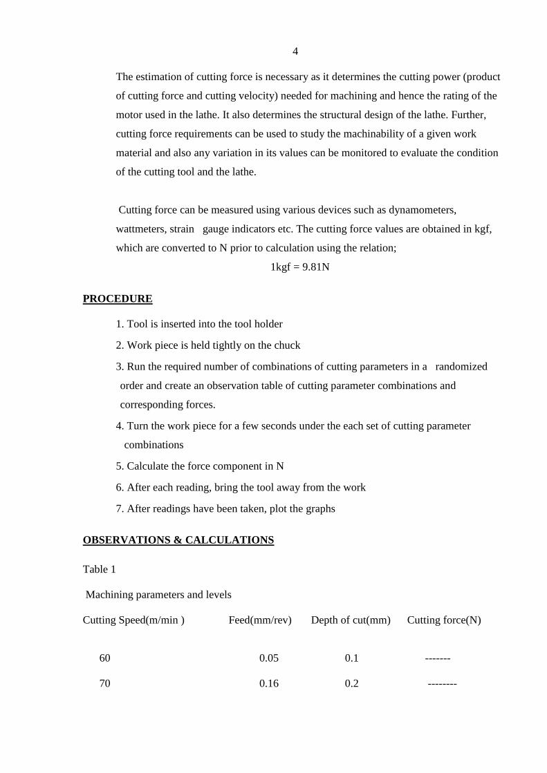
EXP. NO:2
EXERCICES ON CENTRE LATHE: EFFECT OF CUTTING PARAMETERS ON CUTTING FORCE DURING TURNING MILD
STEEL.
AIM :
To study the effect of cutting parameters such as Spindle speed, Feed rate and Depth of cut
on the cutting Force in one face of the tool holder during turning operation under different
combinations of cutting parameters.
EQUIPMENT USED: 1. Centre Lathe operating at safe extreme cutting
2. Lathe tool dynamometer
3. Cutting tool
4. Work piece (Mild steel)
THEORY
For turning operation, there are three components of cutting forces.
1. Fc: Primary cutting force acting in the direction of the cutting velocity vector. This
force is generally the largest force and accounts for 99% of the power required by the
process.
2. Ff : Feed force acting in the direction of the tool feed. This force is usually about 50%
of Fc but accounts for only a small percentage of the power required because feed rates
are usually small compared to cutting speeds.
3. Fr : radial or thrust force acting perpendicular to the machined surface. This force is
typically about 50% of Fr and contributes very little to power requirements because
velocity in the radial direction is negligible.
The cutting force (Fc) is the component of total applied force exerted by the tool on the
work piece in order to carry out machining which acts tangential to the work piece
surface at the cutting zone.
4
The estimation of cutting force is necessary as it determines the cutting power (product
of cutting force and cutting velocity) needed for machining and hence the rating of the
motor used in the lathe. It also determines the structural design of the lathe. Further,
cutting force requirements can be used to study the machinability of a given work
material and also any variation in its values can be monitored to evaluate the condition
of the cutting tool and the lathe.
Cutting force can be measured using various devices such as dynamometers,
wattmeters, strain gauge indicators etc. The cutting force values are obtained in kgf,
which are converted to N prior to calculation using the relation;
1kgf = 9.81N
PROCEDURE
1. Tool is inserted into the tool holder
2. Work piece is held tightly on the chuck
3. Run the required number of combinations of cutting parameters in a randomized
order and create an observation table of cutting parameter combinations and
corresponding forces.
4. Turn the work piece for a few seconds under the each set of cutting parameter
combinations
5. Calculate the force component in N
6. After each reading, bring the tool away from the work
7. After readings have been taken, plot the graphs
OBSERVATIONS & CALCULATIONS
Table 1
Machining parameters and levels
Cutting Speed(m/min ) Feed(mm/rev) Depth of cut(mm) Cutting force(N)
60 0.05 0.1 -------
70 0.16 0.2 --------

5
80 0.25 0.3 --------
The cutting force obtained for different cutting speed by varying the feed with constant depth of
cut is shown in figure 3. As the cutting speed increases the cutting force decreases. As the feed
increases from 0.05 to 0.25 mm/rev the magnitude of all the forces increases. As the cutting
speed increases with a feed of 0.05 mm/rev the machining become steady resulting indrop in
force. The decrement of force for different speed immoderate for feed 0.16 mm/rev. For a feed
of 0.25 mm/rev the cutting forces comes down up to 70 m/min due to thermal softening of work
material and then the forces decreases gradually. Similar trend is observed for mild steel
RESULT
The mild steel was turned to study the effect of machining parameters such as cutting speed,
feed and depth of cut on cutting forces.

6
Exp. NO:3 EXCERCISES ON SHAPING MACHINE: FLAT SURFACES AND KEY WAY
AIM
To perform exercise on shaping machine to obtain flat surfaces and key way.
MATERIALS REQUIRED Cast Iron cube of size 50 mm
TOOLS REQUIRED
1. “V” nose tool
2. Square nose tool
3. Vernier Height Gauge
4. Centre punch
5. Ball peen hammer.
6. Try square.
LIST OF OPERATIONS
1. Machining Flat surfaces
2. Marking
3. Punching
4. Key way cutting
PROCEDURE
1. Copy the drawing.
2. Fix the tool and work piece in position.
3. Adjust the stroke length properly.
4. Machining surfaces to obtain the required shape.
5. Mark the dimensions of key way.
6. Perform key way cutting.
7. Check the dimensions.

7
RESULT:
Machined the flat surfaces and key way on the work piece.

8
Exp NO:4
EXCERCISES ON SLOTTING MACHINE : FLAT SURFACES AND KEY WAY
AIM
To perform exercise on slotting machine to obtain flat surfaces and key way.
MATERIALS REQUIRED
Cast Iron cube of size 50 mm
TOOLS REQUIRED
1. “V” nose tool
2. Square nose tool
3. Vernier Height Gauge
4. Centre punch
5. Ball peen hammer.
6. Try square.
LIST OF OPERATIONS
1. Machining Flat surfaces
2. Marking
3. Punching
4. Key way cutting
PROCEDURE
1. Copy the drawing.
2. Fix the tool and work piece in position.
3. Adjust the stroke length properly.
4. Machining the top of the cube, followed by any two adjacent

9
sides then check perpendicularity of these sides.
5. Mark the dimensions of key way.
6. Perform key way cutting.
7. Check the dimensions.
RESULT:
Machined the flat surfaces and key way on the work piece.

10
Exp NO:5.
EXCERCISES ON MILLING MACHINE: SPUR GEAR AND KEY WAY CUTTING
AIM
To practice on milling machine to perform spur gear and key way cutting.
MATERIALS REQUIRED
1. Cast Iron gear blank of size 80 mmØ, 25 mm thick.
2. Cast Iron cube of size 50 mm.
TOOLS REQUIRED
1. Vernier caliper
2. “V” nose tool
3. Gear milling cutter
4. Side Milling cutter
4. Screwed mandrel
CALCULATIONS
1. Determination of gear blank (To cut 2.5 module, 28 teeth)
Gear blank diameter = m (Z+2)
= 2.5 (28 +2)
= 75 mm.
Tooth depth = 2.25 m
= 2.25 X 2.5
= 5.625 mm.
Cutter pitch = 3 m
= 3 X 2.5
= 7.5 mm.
2. Indexing

11
Index crank movement = 40 / n
= 40 / 28
= 1 3/7
One full rotation and 9 holes in 21 hole circle in index plate.
3. Selection of gear cutter
= Cutter No:4 selected(range: 25 to 34 teeth)
LIST OF OPERATIONS
1. Outer diameter turning.
2. Indexing
3. Gear cutting
4. Milling Key way
PROCEDURE
SPUR GEAR CUTTING
1. Copied the drawing.
2. Turned the gear blank to the required diameter and chamfered its two edges.
3. Fixed the gear cutter on the milling machine arbor.
4. Performed the Setting of Dividing head and Milling machine table.
5. The gear blank is mounted on a mandrel which is supported between the chuck of the
dividing head and center of the tail stock. At a time one tooth space is cut by the milling cutter,
and a dividing head is used to index the job to the next required tooth space. The cutter is
chosen according to the module and number of teeth of the gear to be cut. Before the gear can
be cut, it is necessary to check the cutter centered accurately relative to the gear holding
mandrel. One way is to adjust the machine table vertically and horizontally until one corner of
the cutter just touches the tail stock center. After centering of table, table make downward
direction. The table is then fed vertically so that the blank just touches the cutter. The vertical
dial is then set to zero. This is required to give the depth of cut on the job. After proper depth of
cut, started gear cutting.

12
After one tooth space is cut, the blank is indexed through 1/z revolution by means of the
dividing head, and the process is repeated until all the teeth are cut.
Gear cutting done with proper depth of cut.
MILLING KEY WAY
1. Copied the drawing.
2. Fixed the work piece on machine vice.
3. Fixed the side milling cutter on the arbor.
4. Performed key way milling with proper depth of cut.
5. Check the dimensions.
RESULT:
The spur gear is formed on the work piece. Key way is formed on the work piece. Studied the
method of Indexing.

13

14
Exp. No:6 EXERCISES ON DRILLING MACHINE: DRILLING, COUNTER SINKING AND TAPPING
AIM
To perform the operations such as drilling, counter boring and tapping using drilling machine.
MATERIALS USED
Mild steel flat pieces of 100 X 30 X 6 mm thick.
TOOLS AND EQUIPMENTS USED
Drilling machine, steel rule,, try square, drill bits, couter boring tool and tapping tool.
OPERATIONS TO BE CARRIED OUT
1. Cleaning
2. Marking
3. Punching
4.Drilling
5. Counter boring
6. Tapping
PROCEDURE
1. Clean the mild steel flat piece surfaces thoroughly from rust, dust particles, oil and grease.
2. Mark and punch on the work piece as per the given dimensions
3. Mount the work piece on drilling machine
4. The drill bit is inserting into the tool holder
5. Check the alignment of the tool and work piece
6. Drill the work piece as per the required dimensions
7. Counter boring is done using counter boring tool
8. Form internal thread using tapping tool.
9. Check all dimensions.
RESULT
The operations such as drilling, counter boring and tapping is done using drilling machine

15
DRILLING , COUNTER SINKING AND TAPING ON MS PLATE.

16
EXP.NO:7 EXERCISES ON DRILLING MACHINE: THE EFFECT OF SPEED
ON THRUST AND TORQUE GENERATED DURING A DRILLING PROCESS.
AIM
To study the effect of the drilling speed on the torque and thrust generated under different
combinations of these parameters.
MATERIALS USED
Mild steel flat pieces of 100 X 30 X 6 mm
TOOLS AND EQUIPMENT USED
Vertical drilling machine
Drilling tool dynamometer
Steel rule, Try square, drill bit.
OPERATIONS TO BE CARRIED OUT
1. Cleaning
2. Marking
3. Punching
4. drilling
5. Record the thrust and torque reading from dynamometer.
PROCEDURE
1. Clean the mild steel flat piece surfaces thoroughly from rust ,dust particles, oil and grease.
2. Mark and punch on the work piece as per the given dimensions
3. Mount the work piece on drilling machine
4. The drill bit is insert into the tool holder
5. Check the alignment of the tool and work piece
6. Drill the work piece as per the required dimensions
7. Record both the values Thrust and Torque values in N and Nm from drill tool dynamometer
8. After each reading, bring the drill away from the work and note if the reading drops to zero
9. Similarly, drill the work piece for a few seconds under different speeds of clockwise and
find the thrust and torque.
10. After readings have been taken, plot the Thrust and Torque vs Speed

17
OBSERVATION AND CALCULATIONS
RESULT
Studied the effect of the drilling speed on the torque and thrust generated under different
combinations of these parameters.
SPEED (RPM) THRUST (N) TORQUE (N-m)

18
Exp. No:8 EXERCISES ON WELDING: SINGLE V- BUTT JOINT
AIM
To make a single V-butt joint, using the given mild steel flat pieces and by arc welding.
MATERIALS USED
Two mild steel flat pieces of 124 X 30 X 6 mm
TOOLS AND EQUIPMENTS USED
Arc welding machine, Mild steel electrodes, Electrode holder, Ground clamp, Earth clamp, Flat
nose Tong, Face shield, Ball peen hammer, Chipping hammer, wire brush, steel rule, hack saw,
try square and Grinding machine.
OPERATIONS TO BE CARRIED OUT
1. Cutting and cleaning of the work pieces.
2. Filing
3. Tack welding
4. Full welding
5. Cooling
6. Chipping
7. Finishing
PROCEDURE
1. Cut the two mild steel flat pieces of given dimensions and clean the
Surface’s thoroughly from rust, dust particles, oil and grease.
2. Remove the sharp corners and burrs by filing and prepare the work pieces for single
V- butt joint.
3. The work pieces are positioned on the welding table to form a V-butt joint with the
required V- groove.
4. The electrode is fitted into the electrode holder and the welding ampere is set to a proper
value. (90A to 130A)
5. The ground clamp is fastened to the welding table.
6. Wearing the apron, hand gloves, using the face shield, and holding the piece’s, the arc is
struck and the work pieces are tack weld at the end of the both sides.
7. The alignment of the butt joint is checked and the tack weld pieces are reset, if required.
8. Welding is then carried out throughout the length of the butt joint.
9. Remove the slag, spatters and clean the joint.

19
RESULT
The single V-butt joint is thus made, using the tools and equipments mentioned above.
20
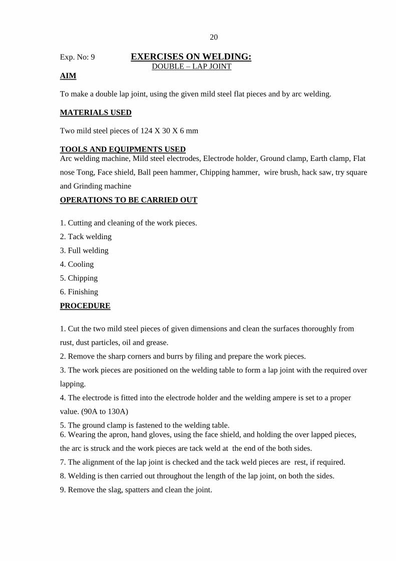
Exp. No: 9 EXERCISES ON WELDING: DOUBLE – LAP JOINT
AIM
To make a double lap joint, using the given mild steel flat pieces and by arc welding.
MATERIALS USED
Two mild steel pieces of 124 X 30 X 6 mm
TOOLS AND EQUIPMENTS USED
Arc welding machine, Mild steel electrodes, Electrode holder, Ground clamp, Earth clamp, Flat
nose Tong, Face shield, Ball peen hammer, Chipping hammer, wire brush, hack saw, try square
and Grinding machine
OPERATIONS TO BE CARRIED OUT
1. Cutting and cleaning of the work pieces.
2. Tack welding
3. Full welding
4. Cooling
5. Chipping
6. Finishing
PROCEDURE
1. Cut the two mild steel pieces of given dimensions and clean the surfaces thoroughly from
rust, dust particles, oil and grease.
2. Remove the sharp corners and burrs by filing and prepare the work pieces.
3. The work pieces are positioned on the welding table to form a lap joint with the required over
lapping.
4. The electrode is fitted into the electrode holder and the welding ampere is set to a proper
value. (90A to 130A)
5. The ground clamp is fastened to the welding table.
6. Wearing the apron, hand gloves, using the face shield, and holding the over lapped pieces,
the arc is struck and the work pieces are tack weld at the end of the both sides.
7. The alignment of the lap joint is checked and the tack weld pieces are rest, if required.
8. Welding is then carried out throughout the length of the lap joint, on both the sides.
9. Remove the slag, spatters and clean the joint.

21
RESULT
The double lap joint is thus made, using the tools and equipments mentioned above
22
Exp. No: 10 EXERCISES ON GRINDING MACHINE:
GRINDING OF TOOL ANGLES OF A SINGLE POINT LATHE TOOL AND ITS
MEASUREMENT USING TMM
AIM
The primary objective of this experiment is to grind the single point cutting tool with the given
nomenclature and measure angles using tool maker’s microscope.
APPARATUS AND MATERIALS REQUIRED
1. Tool and cutter grinder
2. Tool maker’s microscope
3. Universal vice
4. HSS tool blank
THEORY
The tool bit is usually made of high-speed steel. Correct grinding of the lathe tool cutter bit is
essential for good lathe work, because a properly ground cutter bit will produce better results, will
last longer, and will cut more readily than a tool bit which has been improperly ground. Correct
grinding of the lathe tool cuter bit involves grinding the correct angles on the tool bit for the turning
job that is to be done, and for the material that is to be turned.
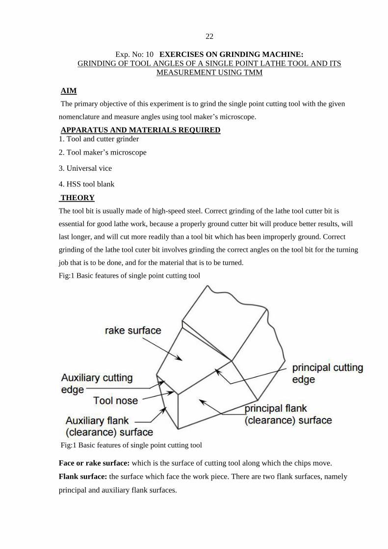
Fig:1 Basic features of single point cutting tool
Fig:1 Basic features of single point cutting tool
Face or rake surface: which is the surface of cutting tool along which the chips move.
Flank surface: the surface which face the work piece. There are two flank surfaces, namely
principal and auxiliary flank surfaces.

23
Cutting edge: edge which removes material from the work piece. There are two cutting edges.
The principal cutting edge performs the function of major material removal and is formed by
the intersection line of rake face with the principal flank surface. The auxiliary cutting edge,
often called as end cutting edge, is formed by intersection of rake face with the auxiliary flank
surface.
Corner or cutting point: The meeting point of principal and auxiliary cutting edges. Often a
nose radius is provided to avoid a sharp corner.
SIGNIFICANCE OF TOOL ANGLES
Rake angle: Angle of inclination of rake surface from reference plane
The rake angle has the following function:
1. It allows the chip to flow in convenient direction
2. It reduces the cutting force required to shear the metal and consequently helps to increase the
tool life and reduce the power consumption. It provides keenness to the cutting edge.
3. It improves surface finish
Clearance angle: Angle of inclination of clearance or flank surface from the finished surface. It
reduces rubbing action between the tool and the work piece.
Side cutting edge angle: The angle between side cutting edge and the side of the tool shank. It
is often referred to as the lead angle.
The following are the advantages of increasing this angle,
1. It increases tool life as, for the same depth of cut; the cutting force is distributed on a wider
surface
2. It diminishes the chip thickness for the same amount of feed and permits greater cutting
speed.
3. It dissipates heat quickly for having wider cutting edge.
End Cutting Edge Angle: The angle between the end cutting edge and a line perpendicular to
the shank of the tool shank is called end cutting edge angle.
The function of end cutting edge angle is to prevent the trailing front cutting edge of the tool
from rubbing against the work. A large end cutting edge angle unnecessarily weakens the tool.
PROCEDURE
1. Mount the tool vertically on the universal vice.
2. Set all the axis of the fixture to zero.

24
3. To grind the principal flank of a single point turning tool, set the required angles in the vice
by rotating its two arms, so that the normal is brought at right angle to the grinding face of the
wheel. The face to be ground is shown in following figure.
4. Start the grinding operation by providing small depth of cut and feed.
5. Repeat the procedure for grinding various angles such as end cutting edge angle and end
relief angle.
6. By moving the arms, bring it back to its original position and remove the tool from the vice.
7. Align the axis of the tool in the horizontal position.
8. Rotate the fixture through back rake angle and side rake angle, so as to obtain the rake face
parallel to the grinding wheel. Required face is shown in figure.
9. Un mount the tool from the vice.
10. Side cutting edge angle, end cutting edge angle and end relief angle can be directly
measured by using tool maker’s microscope.
11. Back rake, side rake and side relief angles are measured using dial gauge and fixtures used
for aligning the tool in the required direction.
OBSERVATION TABLE
SI
No
Tool angle names Initial
reading
Final
reading
Difference
(x)
Given
value(y)
Error
(x-y)
1 Bake rake angle
2 Side rake angle
3 End relief angle
4 Side relief angle
5 End cutting edge angle
6 Side cutting edge angle
PRECAUTIONS
1. Small amount of feed should be given so as to avoid breakage of tool and damage to grinding
wheel.
2. As vice is heavy, care should be taken while handling it.
3. Keep away from the grinding zone to avoid spark injury.
RESULT:
The single point cutting tool is thus made with the given nomenclature and measure angles using
tool maker’s microscope.

25
METALLURGY

26
EXP. NO:11 SPECIMEN PREPARATION : FOR METALLOGRAPHIC EXAMINATION AND STUDY OF METALLURGICAL
MICROSCOPE
AIM:
a) To prepare the given mild steel specimen for metallographic examination.
b) To study the constructional details of Metallurgical Microscope and observe the micro
structure of the prepared specimen.
APPARATUS AND MATERIALS REQUIRED:
Metallurgical microscope, disc polishing machine, emery papers, lapping cloth, alumina
powder, etchants, sample of metal.
THEORY:
The microstructure of metal decides its properties. An optical microscope is used to study the
microstructure. A mirror polished surface of the metal is required for metallographic study.
PROCEDURE OF SPECIMEN PREPARATION:
a) Cut the specimen to the required size (small cylindrical pieces of 10 to 15mm diameter with
15mm height (Or) 10mm cubes.
b) The opposite surfaces (circular faces in case of cylindrical pieces) are made flat with
grinding or filling. A Small chamfer should be ground on each edge for better handling. (If the
sample is small it should be mounted)
c) Belt grinding: One of the faces of the specimen is pressed against the emery belt of the belt
grinder so all the scratches on the specimen surface are unidirectional
d) Intermediate polishing: - The sample is to be polished on 1/0, 2/0, 3/0, 4/0 numbered emery
papers with Increasing fineness of the paper. While changing the polish paper, the sample is to
be turned by 900 so that new scratches shall be exactly perpendicular to previous scratches.
e) Disc polishing (fine polishing):- After polishing on 4/0 paper the specimen is to be polished
on disc Polishing machine (Buffing machine). In the disc-polishing machine a disc is rotated by
a vertical shaft. The disc is covered with velvet cloth. Alumina solution is used as abrasive.
Alumina solution is sprinkled continuously over the disc and the specimen is gently pressed
against it. In case of Non-ferrous metals Such as Brass, Brass is used instead of Alumina and
water. The polishing should be continued till a Mirror polished surface is obtained.

27
f) The sample is then washed with water and dried.
g) Etching:- The sample is then etched with a suitable etching reagent, detailed in article 5.
h) After etching the specimen should be washed in running water and then with alcohol and
then finally dried. i) The sample is now ready for studying its microstructure under the
microscope. ETCHING: Except for few cases a polished metallic surface can’t reveal the
various constituents (phases). Hence specimen should be etched to reveal the details of the
microstructure i.e. a chemical reagent should be applied on the polished surface for a definite
period of time. This reagent preferentially attacks the grain boundaries revealing them as thin
lines. Thus under the microscope the grain structure of the metal becomes visible after etching
i.e. grain boundary area appears dark and grains appear bright. The rate of etching not only
depends on the solution employed and composition of the material but also on the uniformity of
the material. A few etching reagents, their composition and their application are given below.
Sl.No Name of Etchant composition Application
1
2
3
4
5
6
7
8
Nital a) 5% Nital
b) 2% Nital
Picral
Marbel’s reagent
Murakami’s reagent
Sodium hydroxide
Vilella’s reagent
Kellers reagent
Ammonium
persulphate
Nitric. acid (5ml) and Abs. Methyl
alcohol (95ml) Nitric acid (2ml) and
Abs. Methyl alcohol (98ml)
Picric acid (4gm) and Abs ethyl
alcohol (96 ml)
Copper sulphate (4 gm),
Hydrochloric acid (20ml) and water
(20ml)
Potassium ferri cyanide, (10grms),
KOH (10grms) and water (100ml).
Sodium hydroxide (10gm) and
water(90ml)
Hydro fluoric acid (20ml), Nitric acid
(10ml) and Glycerene (30ml)
Hydro fluoric acid (1 ml), Hydro
chloric acid (1.5 ml), Nitric acid(2.5
ml) and Water (95 ml)
Ammonium persulphate (10gm) And
General structure of
iron and steel
General structure of
iron and steel
General structure of
iron and steel
Stainless steels
Stainless steels
Aluminium alloys
Aluminium & its
alloys
Duralumin

28
Water(90ml) FeCl3 (5gm), HCl acid
(2ml)
METALLURGICAL MICROSCOPE:
Metallurgical microscope is used for micro and macro examination of metals. Micro
examination of specimens yields valuable metallurgical information of the metal. The absolute
necessity for examination arises from the fact that many microscopically observed structural
characteristics of a metal such as grain size, segregation, distribution of different phases and
mode of occurrence of component phases and non metallic inclusions such as slag, sulfides etc.,
and other heterogeneous condition (different phases) exert a powerful influence on mechanical
properties of the metal. If the effect of such external characteristics on properties or the extent
of their presence is known, it is possible to predict as to how metal will behave under gone by
the metal. Study of structure of metals at magnifications ranging from 50X to 2000X is carried
out with the aid of metallurgical microscope. A Metallurgical microscope (shown in fig) differs
with a biological microscope in a manner by which specimen of interest is illuminated. As
metals are opaque their structural constituents are studied under a reflected light. A horizontal
beam of light from an appropriate source is directed by means of plane glass reflectors
downwards and through the microscope objective on to the specimen surface. A certain amount
of this light will be reflected from the specimen surface and that reflected light, which again
passes through the objective, will form an enlarged image of the illuminated area. A microscope
objective consists of a number of separate lens elements which are a compound group behave as
positive and converging type lens system of an illuminated object. Specimen is placed just
outside the equivalent front focus point of objective. A primary real image of greater dimension
than those of object field will be formed at some distance beyond the real lens element.
Objective size of primary image w.r.t object field will depend on focal length of objective and
front focus point of objective. By appropriately positioning primary image w.r.t a second
optical system, primary image may be further enlarged by an amount related to magnifying
power of eyepiece. As separation between objective and eyepiece is fixed at same distance

29
equivalent to mechanical tube length of microscope, primary image may be properly positioned
w.r.t eye piece. By merely focusing microscope i.e. increase or decrease the distance between
object plane and front lens of objective the image is located at focal point. Such precise
positioning of primary image is essential in order that final image can be formed and rendered
visible to observer when looking into eyepiece. If now entrance pupil of eye is made to coincide
with exit pupil of eyepiece, eyepiece lens is in conjunction with cornea lens in eye will form a
second real image on retina. This retrieval image will be erect, un reversed owing to the manner
of response of human brain to excitation of retina. The image since it has no real existence,
known as virtual image and appears to be inverted and reversed with respect to object field6.1
Principle: . 6.1.1. MAGNIFICATION: The total magnification is the power of objective
multiplied by power of eyepiece (Power of eye piece) (Distance from eye piece to object) /
Focal length of object The magnification is marked on the side of objective.
CONSTRUCTION:
The microscope consists of a body tube (refer Fig 1.1), which carries an objective below, and an
eyepiece above with plane glass vertical illuminator immediately above the objective. Incident
light from a source strikes illuminator at 45 0 , part of which is reflected on to the specimen.
Rays after reflection pass through the eye again. Working table is secured on heavy base. The
microscope has compound slide to give longitudinal and lateral movements by accurate screws
having scale and venires. Vertical movement of specimen platform is made by a screw to
proper focusing. For getting perfect focusing fine adjustment of focusing can be made use of.
1. Light filters: These are used in metallurgical microscope and are essentially of three types a.
Gelatin sheets connected between two planes of clean glass b. Solid glass filters c. Liquid dye
solution Solid glass filters are more preferable as they are more durable. Usually light filters are
used principally to render a quality of illumination. Hence filters improve degree of resolution.
A METZ - 57 model microscopes is used in the laboratory.
2 Optical compilations: Eye pieces and objectives of different magnifications are available.
Huygens eyepieces: 5X, 10X Achromatic objectives: 5X, 10X, 45X
PRECAUTIONS:
a. Ensure mirror polished surface of specimen before etching.
b. Fine focusing should be done only after correct focusing has been done.
c. The glass lens should not be touched with fingers.
RESULT:
Hence prepared a mild steel specimen for metallographic examination.

30
EXP.NO:12 HARDNESS MEASUREMENT OF MILD STEEL
SPECIMAN , APPLYING VARIOUS HEAT
TREATMENT PROCESSES. AIM:
To analyze the mechanical behavior and microstructure characteristic change of
mild steel specimen, applying various heat treatments.
APPARATUS:
Furnace
Brinnell Hardness tester
Mild steel Specimens (25 mm dia.& 20mm thick)
Optical micro scope
Disc polishing machine
Emery papers ( 80,120,240,400 & 600)
Etchants
Alumina powder.
THEORY:
Heat treatment is a process of heating the metal below its melting point and holding it
at that temperature for sufficient time and cooling at the desired rate to obtain the
required Properties. The various heat treatment processes are annealing, normalizing,
tempering, hardening, mar tempering, austempering.
Chemical composition of Mild Steel
Iron
family
C% Si% Mn % S% P% Cu% Fe%
Mild
steel
016 – 0.18
0.4
0.7 – 0.9
0.04
0.04
0.6
Remaininig
PROCEDURE:
The following steps were carried out;
1. Samples of Mild Steel were prepared for mechanical properties test.
2. After that the following heat treatment is to be carried out.
For annealing: In this case the specimen was put in the furnace for 9100C and we
kept it in this situation for approximately 70 minutes. After that it was cooled in the
furnace so that it was cooled down at a very slow rate.
31
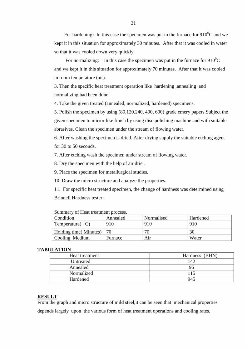
For hardening: In this case the specimen was put in the furnace for 9100C and we
kept it in this situation for approximately 30 minutes. After that it was cooled in water
so that it was cooled down very quickly.
For normalizing: In this case the specimen was put in the furnace for 9100C
and we kept it in this situation for approximately 70 minutes. After that it was cooled
in room temperature (air).
3. Then the specific heat treatment operation like hardening ,annealing and
normalizing had been done.
4. Take the given treated (annealed, normalized, hardened) specimens.
5. Polish the specimen by using (80,120.240, 400, 600) grade emery papers.Subject the
given specimen to mirror like finish by using disc polishing machine and with suitable
abrasives. Clean the specimen under the stream of flowing water.
6. After washing the specimen is dried. After drying supply the suitable etching agent
for 30 to 50 seconds.
7. After etching wash the specimen under stream of flowing water.
8. Dry the specimen with the help of air drier.
9. Place the specimen for metallurgical studies.
10. Draw the micro structure and analyze the properties.
11. For specific heat treated specimen, the change of hardness was determined using
Brinnell Hardness tester.
Summary of Heat treatment process.
Condition Annealed Normalised Hardened
Temperature( 0
C) 910 910 910
Holding time( Minutes) 70 70 30
Cooling Medium Furnace Air Water
TABULATION
Heat treatment Hardness (BHN)
Untreated 142
Annealed 96
Normalized 115
Hardened 945
RESULT
From the graph and micro structure of mild steel,it can be seen that mechanical properties
depends largely upon the various form of heat treatment operations and cooling rates.

32
EXP.NO:13 EFFECT ON MECHANICAL PROPERTIES AND MICRO
STRUCTURE OF MILD STEEL ,APPLYING
VARIOUS HEAT TREATMENT PROCESSES. AIM:
To analyze the mechanical behavior and microstructure characteristic change of
mild steel specimen, applying various heat treatments.
APPARATUS:
Furnace
Brinnell Hardness tester
Mild steel Specimens (25 mm dia.& 20mm thick)
Optical micro scope
Disc polishing machine
Emery papers ( 80,120,240,400 & 600)
Etchants
Alumina powder.
THEORY:
Heat treatment is a process of heating the metal below its melting point and holding it
at that temperature for sufficient time and cooling at the desired rate to obtain the
required Properties. The various heat treatment processes are annealing, normalizing,
tempering, hardening, mar tempering, austempering.
Chemical composition of Mild Steel
Iron
family
C% Si% Mn % S% P% Cu% Fe%
Mild
steel
016 – 0.18
0.4
0.7 – 0.9
0.04
0.04
0.6
Remaininig
PROCEDURE:
The following steps were carried out;
1. Samples of Mild Steel were prepared for mechanical properties test.
2. After that the following heat treatment is to be carried out.
For annealing: In this case the specimen was put in the furnace for 9100C and we
kept it in this situation for approximately 70 minutes. After that it was cooled in the
furnace so that it was cooled down at a very slow rate.

33
For hardening: In this case the specimen was put in the furnace for 9100C and we
kept it in this situation for approximately 30 minutes. After that it was cooled in water
so that it was cooled down very quickly.
For normalizing: In this case the specimen was put in the furnace for 9100C
and we kept it in this situation for approximately 70 minutes. After that it was cooled
in room temperature (air).
3. Then the specific heat treatment operation like hardening ,annealing and
normalizing had been done.
4. Take the given treated (annealed, normalized, hardened) specimens.
5. Polish the specimen by using (80,120.240, 400, 600) grade emery papers.Subject the
given specimen to mirror like finish by using disc polishing machine and with suitable
abrasives. Clean the specimen under the stream of flowing water.
6. After washing the specimen is dried. After drying supply the suitable etching agent
for 30 to 50 seconds.
7. After etching wash the specimen under stream of flowing water.
8. Dry the specimen with the help of air drier.
9. Place the specimen for metallurgical studies.
10. Draw the micro structure and analyze the properties.
11. For specific heat treated specimen, the change of hardness was determined using
Brinnell Hardness tester.
SUMMARY OF HEAT TREATMENT PROCESS.
Condition Annealed Normalised Hardened
Temperature( 0
C) 910 910 910
Holding time( Minutes) 70 70 30
Cooling Medium Furnace Air Water
TABULATION
Heat treatment Hardness (BHN)
Untreated 142
Annealed 96
Normalized 115
Hardened 945
RESULT
From the graph and micro structure of mild steel,it can be seen that mechanical properties
depends largely upon the various form of heat treatment operations and cooling rates.