manufacturing, inc. - · pdf filemkt manufacturing, inc. standard new product warranty ....
TRANSCRIPT

MANUFACTURING, INC. 1198 PERSHALL RD. ST. LOUIS, MO 63137, USA Telephone: 314-388-2254 Website: www.mktpileman.com
SERVICE, OPERATING, MAINTENANCE AND PARTS MANUAL FOR THE V-5ESC HYDRAULIC VIBRATORY PILE DRIVER/EXTRACTOR SYSTEM
WARNING THIS PRODUCT MAY CONTAIN OR EMIT CHEMICALS SUCH AS DIESEL ENGINE EXHAUST AND SOME OF ITS CONSTITUENTS THAT ARE KNOWN TO THE STATE OF CALIFORNIA TO CAUSE CANCER, BIRTH DEFECTS, AND OTHER REPRODUCTIVE HARM.
OCCUPATIONAL HEALTH WARNINGS:
1. Construction equipment frequently operates at very high sound levels. Such sound levels can be harmful to the human hearing system. Sustained exposure to such high sound levels can permanently impair one’s hearing. Hearing protection should be worn by anyone and everyone within close proximity to a Vibratory Pile Driver/Extractor System.
2. Do not install, operate, or service the V-5ESC until having thoroughly read this manual and having received instructions from an MKT factory authorized service representative or properly trained, experienced operator. Make this manual available to all persons responsible for the operation, installation, servicing and maintenance of this product. Also wear proper clothing and personal protection equipment such as, safety shoes, safety goggles, hearing protection and hard hat

MKT MANUFACTURING, INC. STANDARD NEW PRODUCT WARRANTY
EXPRESS LIMITED PARTS WARRANTY FOR NEW PRODUCTS
MKT MANUFACTURING, INC. (“MKT”) warrants to the first user (“User”) of any new product (whether such new product is sold directly to the customer by MKT or through a distributor) that such new product will be free from defects in material or workmanship for a period of ninety (90) days beginning on the date that such new product is delivered to the User. This Express Limited Parts Warranty (“Warranty”) applies only to the first User of the new product, and not any subsequent users, regardless of whether such subsequent user becomes the owner of the new product or uses the product within such ninety (90) day warranty period. In no event shall this Warrant y extend for more than twelve (12) months from the date that MKT ships the product, whether to a User or to a distributor which may or may not use the product. This Warranty applies to new products only. This Warranty is subject to the following terms and conditions.
If User believes that the product has a defect in the materials or workmanship, User shall send notice of such defect in writing to MKT within the ninety (90) day warranty period. MKT shall have the right to inspect the product for defects, and any parts which appear to MKT upon inspection to have been defective in material or workmanship shall be repaired or replaced at MKT’s option. MKT shall have no other liability to User except for such repair or replacement of those parts determined to be defective. Such repair or replacement parts shall be provided at no cost to the User at such location and during such hours as determined by MKT. This Warranty shall not apply to component parts or accessories of products not manufactured by MKT, or to normal maintenance of the product or to normal maintenance parts required therefor. Replacement or repair parts installed in the products covered by this Warranty are warranted only for the remainder of the Warranty as if such parts were original components of said product. EXCEPT AS EXPRESSLY SET FORTH IN THIS WARRANTY, MKT MAKES NO OTHER WARRANTIES, AND FURTHER DISCLAIMS ALL OTHER WARRANTIES, EXPRESS OR IMPLIED, AND MAKES NO WARRANTY OF MERCHANTABILITY OR FITNESS FOR ANY PARTICULAR PURPOSE.
THIS WARRANTY IS NOT APPLICABLE TO ANY ITEM WHICH MKT SELLS THAT IS WARRANTED DIRECTLY TO THE USER BY THE MANUFACTURER OF SUCH ITEM (IF SUCH MANUFACTURER OF SUCH ITEM IS NOT MKT).
MKT EXCLUDES ALL LIABILITY FOR OR ARISING FROM ANY NEGLIGENCE ON ITS PART OR ON THE PART OF ANY OF ITS EMPLOYEES, AGENTS OR REPRESENTATIVES WITH RESPECT TO THE MANUFACTURE OR SUPPLY OF THE PRODUCT.
MKT shall not be liable to User or any third party for any loss of profits, loss of use, interruption of business, or any indirect, incidental, special, punitive or consequential damages of any kind whatsoever related to the product or the use or operation of the product. In particular, MKT assumes no liability for the results of User and its affiliates based on User’s use of the products furnished by MKT. The maximum total liability of MKT shall be limited to the cost of those parts which MKT has agreed to repair or replace. This limitation applies to all causes of action in the aggregate, including without limitation, breach of contract, breach of warranty, negligence, strict liability, misrepresentations, and other torts. In any jurisdiction in which the above limitations of liability are restricted, MKT’s liability is limited to the greatest extent permitted by law.
Notwithstanding anything in this Agreement to the contrary, MKT shall not be responsible for any costs or charges of User and/or any third party, including but not limited to transportation charges, shipping costs, cost of installation, duty, taxes or any other charges whatsoever including but not limited to any charges or damages due to any delays. If requested by MKT, products or parts for which a warranty claim is made are to be returned transportation prepaid to MKT at MKT’s home office. Any improper use, including operation after discovery of defective or worn parts, operation beyond rated capacity, substitution of parts not approved by MKT, or any alteration or repair by others in such manner as in MKT’s judgment affects the Product materially and adversely, shall void this Warranty.
NO EMPLOYEE OR REPRESENTATIVE IS AUTHORIZED TO CHANGE THIS WARRANTY IN ANY WAY OR GRANT ANY OTHER WARRANTY UNLESS SUCH CHANGE IS MADE IN WRITING AND SIGNED BY AN OFFICER OF MKT AT ITS HOME OFFICE.

TABLE OF CONTENTS
I. INTRODUCTION ............................................................................... 2
II. SAFETY INSTRUCTIONS ................................................................. 3
III. SPECIFICATIONS ........................................................................... 10
IV. EXCAVATOR REQUIREMENTS ..................................................... 11
V. SYSTEM SET-UP INSTRUCTIONS ................................................ 12
VI. START-UP PROCEDURES ............................................................ 16
VII. OPERATING INSTRUCTIONS ........................................................ 20
VIII. MAINTENANCE AND SERVICE INSTRUCTIONS ......................... 24
IX. SERVICE TROUBLE SHOOTING ................................................... 27
X. PARTS AND DRAWING LIST ......................................................... 29
A. V-5Esc GENERAL ASSEMBLY AND PARTS LIST
B. EXCITER CASE ASSEMBLY
C. ECCENTRIC SHAFT ASSEMBLY AND PARTS LIST
D. MOTOT SHAFT ASSEMBLY AND PARTS LIST
E. V-5Esc HYDRAULIC CLAMP ASSEMBLY AND PARTS LIST
F. SIDE CLAMP ASSEMBLY
G. ROTOTILT ASSEMBLY
H. MANIFOLD ASSEMBLY
I. V-5Esc HYDRAULIC SCHEMATIC AND PARTS LIST
J. ELECTRICAL SCHEMATIC
INTRODUCTION | 2
I. INTRODUCTION This manual is exclusively for the MKT V-5ESC Hydraulic Vibratory Pile Driver/Extractor System. The manual for the Rototilt mounting system that attaches the V-5ESC to the excavator is included with this manual. It is your responsibility to read and understand this manual, the Rototilt/Indexator manual, and the excavator manufacturer’s manuals before operating this hydraulic construction tool. Make the following points part of your regular workday.
- Know the limitations and operating characteristics of the Vibratory Pile Driver/ Extractor System.
- Inspect the V-5ESC before each use as specified in this manual and by your - employer. - NEVER use attachments that are not approved by the manufacturer. - NEVER remove or modify any parts of the equipment. - Know the location of other personnel and equipment and make sure they
are at a safe distance before operating. - All visitors or other personnel in the immediate area of operating
equipment must wear all necessary personal protective equipment. The MKT V-5ESC Hydraulic Vibratory Pile Driver/Extractor System is used for installing or removing piling. The five major components of an MKT Vibratory Pile Driver/Extractor include rotating eccentric weights housed in a gear box that generate the vibratory forces to the pile, an elastomer suspension system to isolate the vibratory forces from the excavator, a bottom hydraulic clamp and side clamp system to grip the pile and Rototilt system to position the hammer. There are two rotating eccentric weights in the V-5ESC mounted in special heavy duty spherical roller bearings. One fixed displacement piston hydraulic motor is used to drive a pinion. The two eccentric weights are, in turn, gear driven and timed off the pinion. When operating within its load capabilities, the V-5ESC vibratory is designed to deliver a driving force of about 53 tons to a pile at a rate of 1,700 vibrations per minute.

3 | SAFETY INSTRUCTIONS
II. SAFETY INSTRUCTIONS
The following safety instructions are contained in the text of this manual. Read the entire manual before operating the hammer. Remember SAFETY IS UP TO YOU! Good safety practices not only protect you but also protect the people around you.
The following signal words will be found in this manual and may also be found in other manufacturer’s manuals. These words are intended to alert the operator to a hazard and the degree of severity of the hazard.
indicates a hazardous situation which, if not avoided, will result in death or serious injury.
indicates a hazardous situation which, if not avoided, could result in death or serious injury.
indicates a hazardous situation which, if not avoided, could result in minor injury or moderate injury.
indicates a property damage message.
A. For each lift the operator must review the excavator lifting capacity to determine that the weight of the hammer/ Rototilt assembly plus the load being lifted is within the rated capacity of the excavator.
B. Check that all personnel are clear of the V-5ESC unit
prior to start up.
C. Keep hands clear of all three clamps at all times.
D. Always use pile handling/ safety line to attach the pile to the hammer.
FAILURE TO COMPLY WITH THE FOLLOWING SAFETY
INSTRUCTION AND LOCAL REGULATIONS WILL RESULT IN PROPERTY DAMAGE, SEVERE INJURY OR DEATH.

SAFETY INSTRUCTIONS | 4
E. Leave the pile handling/ safety line attached to the pile at all times if the pile is not stuck securely in the ground.
F. The V-5ESC side clamp attachment is designed to handle a single pile with a MAXIMUM weight of 2 tons. Appropriate pile handling rigging should be supplied by the end user to handle the pile in a safe manner. Attach safe handling cable(s) to lifting eye(s) on the hammer to allow for pile placement in the jaws as shown in figure 1.
G. Before closing the jaws of the bottom clamp, assure that the pile head is firmly against the clamp housing. Gripping the pile with merely the lower end of the jaws will damage the jaws, the clamp slide and/ or other clamp assembly components
H. Stand a safe distance away from the pile and from below the V-5ESC hammer during vibrating operations. Any unobserved or unconnected, loose nut or other fastener may fall.
I. Do not unclamp the jaws from the pile while the hammer is vibrating.
J. Do not pull in excess of the rating of the V-5ESC hammer’s suspension assembly or excess stresses will be put on the suspension assembly damaging one or more parts.
K. Whenever the V-5ESC hammer is observed “dancing or chattering” in place, it should be hoisted until the action stops. Failure to move a pile with the hammer “dancing or chattering” should be cause to promptly abandon the effort before serious damage is done to the hammer. To continue operations the obstruction must be removed or penetrated by switching to another driving system such as a larger vibro or a MKT diesel or air pile hammer.

5 | SAFETY INSTRUCTIONS
IMPORTANT SAFETY INFORMATION Virtually all accidents that involve product operation, maintenance and repair are caused by failure to keep fundamental safety rules or precautions. An accident can often be avoided by identifying potentially unsafe situations before an accident occurs. A person must be alert to potential hazards. This person should also have the necessary training, skills and tools to perform these functions properly. Do not operate or perform any lubrication, maintenance or repair on this equipment until you have read and understand the applicable information in the Operation and Maintenance Manual.
MKT cannot anticipate every possible circumstance that might involve a potential hazard. The warnings in the manuals and on the equipment are therefore not all inclusive. If a tool, procedure, work method or operating technique not specifically recommended by MKT is used, you must satisfy yourself that it is safe for you and others. You should also ensure that the equipment will not be damaged or made unsafe by the operation, lubrication, maintenance or repair procedures you choose.
The information, specifications, and illustrations in the manuals are based on information available at the time it was written. The specifications, torques, pressures, measurements, adjustments, illustrations, and other items can change at any time. These changes can affect the service given to the product. Obtain the complete and most current information before starting any job. MKT and MKT distributors have the most current information available.
GENERAL HAZARD INFORMATION
Use caution when removing filler caps, grease fittings, pressure taps, breathers or drain plugs. Hold a rag over the cap or plug to prevent being sprayed or splashed by liquids under pressure.
Wear a hard hat, protective glasses, hearing protection and other protective equipment as required by job conditions.
Do not wear loose clothing or jewelry that can catch on controls or other parts of the equipment.
Make certain all protective guards and covers are secured in place. Use all cleaning solutions with care.
Never put maintenance fluids into glass containers since glass containers can break.
Report all needed repairs.

SAFETY INSTRUCTIONS | 6
UNLESS INSTRUCTED DIFFERENTLY, PERFORM ALL MAINTENANCE AS FOLLOWS
Stop the hammer.
Refer to excavator operator manual to lockout the excavator auxiliary hydraulic circuit and electrical systems so they cannot energize while working on hammer.
Do not attempt any repairs or adjustments to the hammer while it is running.
Do not attempt repairs you do not understand. Use proper tools; replace or repair broken or damaged equipment.
Block or restrain the equipment, if applicable before operating or performing maintenance.
Do not adjust, or set, hydraulic pressures higher or lower than those specified in the manual.
PRESSURIZED AIR AND WATER
Pressurized air can cause personal injury. When using pressurized air for cleaning, wear a protective face shield, protective clothing and protective shoes.
The maximum air pressure must be below 30 psi (205 kPa) and maximum water pressure must be below 40 psi (275 kPa) for cleaning purposes.
FLUID PENETRATION
Wear eye protection at all times when cleaning the cooling system. Pressurized water could cause debris and/or hot water to be blown and result in personal injury.
Always use a board or cardboard when checking for a leak. Escaping fluid under pressure, even a pin-hole size leak, can penetrate body tissue, causing serious injury or possible death.
If fluid is injected into your skin, it must be treated by a doctor familiar with this type of injury immediately.

7 | SAFETY INSTRUCTIONS
HOSES, LINES, AND TUBES Do not pull on, or attempt to move equipment, with hydraulic hoses.
Do not operate this equipment with hydraulic hoses that are damaged or kinked. Replace damaged hoses immediately.
Do not lift, or support, hydraulic hoses with wire rope slings.
Do not pull kinks in the hoses. Kinks will reduce the hose safety factor by 50 percent.
Do not bend or strike high pressure lines. Do not install bent or damaged lines, tubes or hoses.
Repair any loose or damaged fuel and oil lines, tubes and hoses. Leaks can cause fires.
Inspect all lines, tubes and hoses carefully. Do not use your bare hands to check for leaks. Tighten all connections to the recommended torque.
Check for the following:
- End fittings damaged, leaking or displaced. - Outer covering chafed or cut and wire reinforcing exposed. - Outer covering ballooning locally. - Evidence of kinking or crushing.
Make sure that all clamps, guards and heat shields are installed correctly to prevent vibration, rubbing against other parts, and excessive heat during operation.
OILS Hot oil and components can cause personal injury. Do not allow hot oil or components to contact the skin.
SAFETY INSTRUCTIONS | 8
FIRE OR EXPLOSION PREVENTION All fuels, most lubricants, hydraulic oil, and some coolant mixtures are flammable. Diesel fuel is flammable. Gasoline is flammable. The mixture of diesel and gasoline fumes is extremely explosive.
Do not weld or flame cut on pipes or tubes that contain flammable fluids. Clean them thoroughly with nonflammable solvent before welding or flame cutting on them.
Clean and tighten all electrical connections. Check regularly for loose or frayed electrical wires. Refer to maintenance schedules for interval. Have all loose or frayed electrical wires tightened, repaired or replaced before operating the equipment.
Wiring must be kept in good condition, properly routed and firmly attached. Routinely inspect wiring for wear or deterioration. Loose, unattached, or unnecessary wiring must be eliminated. All wires and cables must be of the recommended gauge and fused if necessary. Do not use smaller gauge wire or bypass fuses. Tight connections, recommended wiring and cables properly cared for will help prevent arcing or sparking which could cause a fire.
FIRE EXTINGUISHER Have a fire extinguisher available and know how to use it. Inspect and have it serviced as recommended on its instruction plate.
CRUSHING OR CUTTING PREVENTION
Support equipment and attachments properly when working beneath them.
Never attempt adjustments while the engine is running unless otherwise specified in this manual.
Stay clear of all rotating and moving parts. Guards should be in place whenever maintenance is not being performed.
Keep objects away from moving fan blades. They will throw or cut any object or tool that falls or is pushed into them.
Wear protective glasses when striking objects to avoid injury to your eyes.
Chips or other debris can fly off objects when struck. Make sure no one can be injured by flying debris before striking any object.

9 | SAFETY INSTRUCTIONS
MOUNTING AND DISMOUNTING
Do not climb on, or jump off the equipment or stand on components which cannot support your weight. Use an adequate ladder. Always use steps and handholds when mounting and dismounting.
Clean steps, handholds and areas of the equipment you will be working on or around.
BEFORE STARTING HAMMER
Make sure that all lifting equipment, including excavator, wire rope, slings, hooks, shackles, etc., are properly sized for the worst case loads anticipated during operations. Check wire rope clips for tightness, and check wire ropes for wear daily.
If there are any questions about the weights, specifications, or performance of the hammer, contact MKT before handling or operating the equipment.
Make sure that ground vibrations will not damage adjacent structures or excavations. Make sure no one is working on or close to the equipment before starting.
HAMMER OPERATION
Only well trained and experienced personnel should attempt to operate or maintain this equipment.
Do not stand any closer to this equipment than necessary when it is in operation. Parts may loosen and fall. Piling may shatter or break.
Do not operate the hammer, excavator boom/arm, piles, wire rope and other equipment within 15’ (5m) of electrical power lines, transformers and other electrical equipment, or within such distance as required by applicable safety codes.
Do not side-load excavator boom/arm or hammer. Dangerous excavator boom/arm or hammer damage may result.

SPECIFICATIONS | 10
III. SPECIFICATIONS
SPECIFICATIONS FOR THE V-5ESC VIBRATORY PILE DRIVER/EXTRACTOR SYSTEM
A. OPERATING DATA – V-5ESC DRIVER/EXTRACTOR
Free Hanging Frequency.................................................................. 1700 CPM Rated Drive Pressure .......................................................................... 3500 PSI Rated Flow ........................................................................................... 90 GPM Free Hanging Amplitude .......................................................................... 1/2 IN Driving Force @ 1700 CPM ............................................................... 53 TONS Clamp Circuit Pressure ....................................................................... 2500 PSI Clamping Force @2500 PSI .............................................................. 62 TONS Maximum Pull Force with Bottom Clamp (8 Shear Blocks) ................ 30 TONS Maximum Pull Force with Side Clamp Assembly ............................... 15 TONS Standard Clamp Jaw Opening ............................................................... 1.25 IN Clamp Cylinder Travel ................................................................................. 2 IN Side Clamp Jaw Opening ............................................................................ 3 IN Net Weight with Side Clamp and Rototilt ......................................... 10750 LBS Maximum Pile Weight ........................................................................ 4000 LBS
*NOTE: Frequency is set to maximize performance on a normal pile, and normal duty cycle. Should overheating occur to exciter due to high duty cycle, it is important that the unit be stopped and allowed to cool down. If overheating persists, reduce hammer cycles to 1400 - 1500 cpm and monitor temperature. If exciter temperature remains high (above 180 degrees Fahrenheit), contact your Factory Authorized Distributor for assistance.

11 | EXCAVATOR REQUIREMENTS
IV. EXCAVATOR REQUIREMENTS
A. The excavator size, stick width and pin dimensions must be compatible with the Rototilt width and pin dimensions.
B. The excavator must be equipped with a uni-directional auxiliary circuit that
can supply 90 GPM to the V-5ESC at 3,500 psi. The 90 GPM needs to be set using a flowmeter to 90 GPM with minimal restrictions in the system. The pressure needs to be set at 3,500 psi dead headed (zero flow). If you have any question on how to properly set flow or pressure please contact your local MKT representative or the factory.
C. The auxiliary hydraulic circuit must supply at least 90 GPM and must flow oil
in one direction only (uni-direction), it cannot have reverse flow, or damage to the V-5ESC hydraulic manifold may result. The circuit should be controlled by an electric on/off switch, not a bi-directional foot pedal.
D. The excavator must have adequate lifting capacity to lift the combined weight
of the hammer and pile at the required working radius.
E. The Rototilt RT80 has a maximum connecting pin size of 90mm and a maximum digging force of 44,960 lbs. If using an excavator with larger than 90mm pins or more than 44,960 lbs. of digging force you must reduce the pin size to 90mm and lower the digging force to 44,960 lbs. Consult your excavator supplier for the proper way to make these modifications.
F. The V-5ESC electrical controls are operated using a 24v positively switched electrical supply. If your excavator system is negatively switched, you will need a relay in-line to operate the V-5ESC electrical controls. Please contact your local excavator dealer to determine what type of electrical system your specific excavator runs.

SYSTEM SET-UP INSTRUCTIONS | 12
V. SYSTEM SET-UP INSTRUCTIONS
A. EXCAVATOR FLOW AND PRESSURE CHECK
Before connecting to the V-5ESC control manifold the auxiliary circuit of the excavator need to be activated to verify the hydraulic flow path. A flowmeter works best to determine this. The V-5ESC requires a flow of 90 GPM with no back pressure at a minimum of 3,500 psi.
Reversing the auxiliary circuit or applying the flow to the manifold Return port will cause damage to the manifold’s internal components.
B. CONNECTION OF HOSES
All V-5ESC hammers are thoroughly tested at the factory and consequently all hoses will be filled with hydraulic fluid. If hoses are replaced or are otherwise unfilled with oil, take necessary steps to fill them before starting the hammer.
1. Three jumper hoses will need to be created in order to connect the
excavator’s axillary circuit supply, return and case drain to the corresponding ports on the V-5ESC control manifold. When jumper hoses are attached to the vibratory unit, extreme care should be made at all times not to kink any of the hoses.
a) Drive Motor Hoses: (2) each 1 ¼” hoses rated for safe operation at the
excavator’s maximum hydraulic pressure capability connected to hydraulic circuit ports (length of hoses to be determined by type of excavator). These hoses need -20 female JIC fittings on one end to plug into control manifold.
b) Motor Drain Hose: (1) each ¾” hose rated for safe operation at the excavator’s maximum hydraulic pressure capability connected to the hydraulic circuit ports (length of hose to be determined by type of excavator). This hose needs a -12 female JIC fitting to plug into control manifold.
CASE DRAIN MOTOR SUPPLY / RETURN

13 | SYSTEM SET UP INSTRUCTIONS
For the case drain line minimal restriction back to the hydraulic reservoir is required.
Failure to connect the drain line to the hydraulic reservoir will cause damage to the internal components of the manifold and cause V-5ESC drive motors to have seal failures.
Whenever the hydraulic line of the V-5ESC system have been disconnected then reconnected for any reason the two side clamp cylinders and bottom clamp cylinder must be bled of entrained air. Please see the Bleeding the Clamps Section in the Start-Up Procedures of this manual for instructions on how to properly bleed the clamps. Any damaged hose within the vibratory hammer should be replaced with a hose of equivalent ratings.
2. Before making any hydraulic hose connections, assure that the connectors
are wiped clean of any dirt or contamination to prevent damage to the components in the hydraulic system.
3. Do not permit mobile equipment to run over any hydraulic hoses. The
hydraulic hoses, even though filled with hydraulic oil, are not able to withstand external compression forces.
4. The ends of the jumper hoses should be carefully wiped clean and
connected, according to size, to the V-5ESC control manifold. 5. Make it a habit whenever hydraulic lines are subsequently disconnected to
immediately cap or plug them to avoid becoming dirty and introducing contamination, into and damage to, the components of the hydraulic system. Assure that the caps and plugs are wiped clean of any dirt or contamination before using.

SYSTEM SET-UP INSTRUCTIONS | 14
C. ELECTRICAL CONNECTIONS
Whether using custom joysticks designed specifically for an excavator or the standard MKT electrical stand, there will be three cords that go down the boom from the excavator to the V-5ESC control manifold.
1. POWER SUPPLY
The cable with the red shrink tube is for the 24v supply. White is positive, black is negative and needs to be connected to a 24v power supply.
2. AUXILIARY CONTORL CIRCUIT
The cable with the blue shrink tube is to be used to control the auxiliary circuit on the excavator. Due to the wide range of excavator controls, please contact your local excavator dealer to determine what type of electrical system your specific excavator runs. This requires a 24v signal; white is positive and black is negative.
If the excavator electrical system is negatively switched, a relay is needed in-line for our auxiliary control to control the system. Please contact a local MKT representative or the factory for information needed to install an in-line relay.
3. MANIFOLD CONNECTIONS
Whether using custom joysticks designed specifically for an excavator or the standard MKT electrical stand, there will be three cords that go down the boom from the excavator to the V-5ESC control manifold. The three cords are the Rototilt control cable
a) Rototilt Control Cable: The Rototilt control cable is has a 10 pin
connector. Run this cable down the boom and connect it to the corresponding 10 pin connector located out at the control manifold of the V-5ESC.
b) Vibrate Solenoid Control: The cable with the green shrink tube is used
to operate the vibrate function of the hammer. Connect the grey electrical connecter, labeled “A”, at the end of this cable to the solenoid stamped #13 on the control manifold.
c) Rototilt Supply Solenoid Control: The cable with the yellow shrink tube
is used to operate the Rototilt supply solenoid of the hammer. Connect the black electrical connecter, labeled “B”, at the end of this cable to the solenoid stamped #12 on the control manifold.

15 | SYSTEM SET UP INSTRUCTIONS
D. V-5ESC DRIVER/EXTRACTOR
The V-5ESC hammer is factory fitted with a suspension assembly and is shipped laying down in a specially designed shipping stand. It is designed to be pinned to the second member of an excavator via the RT-80 Rototilt mounted on top of the suspension. The V-5ESC hammer can be lifted from the horizontal to the vertical without danger of excessive stresses upon its connecting parts or structure.
E. V-5ESC JAW SHIELDS
The Jaw Shields are generally shipped connected to the V-5ESC Clamp Assembly. Before using the V-5ESC, assure that the Jaw Shields are tightly connected (each with four hex head cap screws and lock washers) to the V-5ESC Clamp Assembly. The Jaw Shields not only act as guides for positioning the V-5ESC on a standing pile, but are also necessary to protect the jaws and the clamp assembly from unnatural impact shock and resulting damage.

START-UP PROCEDURES | 16
VI. START-UP PROCEDURES
A. CLEAR THE AREA
Verify all personnel are clear of the vibratory hammer before proceeding.
B. POWERING UP THE CONTROLS
1. With the excavator running turn the power switch on the junction box to the ON position
2. Once the junction box has been powered up push the on button in the upper left corner of the wireless remote. The remote has a timer built into it and if unused for 10 minutes it will shut off the save battery.
Note: The power to the junction box has to be turned on before the remote can be turned on. If the remote is turned on first the system will not recognize the remote.
C. OPERATION OF THE UNIT
Once the proper power up procedures have been completed the unit is ready to be controlled.
1. TILT function is controlled by pushing down on the button to tilt left and the
bottom of the button to tilt right.
2. ROTATE function is controlled by pushing down on the top of the button to rotate left and the bottom of the button to rotate right.

17 | START UP PROCEDURES
1. CLAMP function is controlled by first holding the button up or down on the PTO (push to operate) switch that is located directly to the right of the clamp function button. Once the PTO is held the clamp can now operate by pushing up on the clamp button to open the clamps or down on the clamp button to close the clamps.
Verify again that all personnel are clear before vibrating the clamps. The side clamp cylinders and bottom clamp are on a common hydraulic circuit so all three cylinders will actuate at the same time.
2. VIBRATORY function is controlled by first holding the button up or down on
the PTO (push to operate) switch that is located directly to the right of the vibro function button. While you have the PTO held down you will need to push the vibro switch up to the on position. The V-5ESC will continue to vibrate without holding the buttons until you push the vibro function button down to the off position. NOTE: While turning the V-5ESC off the PTO does not need to be pushed.
Verify again that all personnel are clear before vibrating the V-5ESC.
D. BLEEDING THE CLAMP CIRCUIT
Whenever the hydraulic line of the V-5ESC system have been disconnected then reconnected for any reason the two side clamp cylinders and bottom clamp cylinder must be bled of entrained air. In order to effectively bleed all entrained air from the system the hammer must be in the vertical, upright position.
Contents of hydraulic components may be under pressure and extreme care should be taken when opening or bleeding components.
1st 2nd
1st 2nd

START-UP PROCEDURES | 18
1. BOTTOM CLAMP
Follow the instructions found in the start-up portion of this manual to operate the clamp functions. Close the jaws and hold the clamp close function while you open the bleeder on the back of the bottom clamp.
Do not back vent screw all the way out! Allow oil to vent approximately 30 seconds or until an air free stream of oil comes from each vent screw.
2. SIDE CLAMP CYLINDERS
Follow the instructions found in the start-up portion of this manual to operate the clamp functions. Close the jaws and hold the clamp close function while you open the bleeder on the back of the bottom clamp first. Once the bottom clamp cylinder has been bleed repeat the steps and bleed the top cylinder.
Do not back vent cap all the way out! Allow oil to vent approximately 30 seconds or until an air free stream of oil comes from each vent screw.
BOTTOM 1st TOP 2nd
19 | START UP PROCEDURES
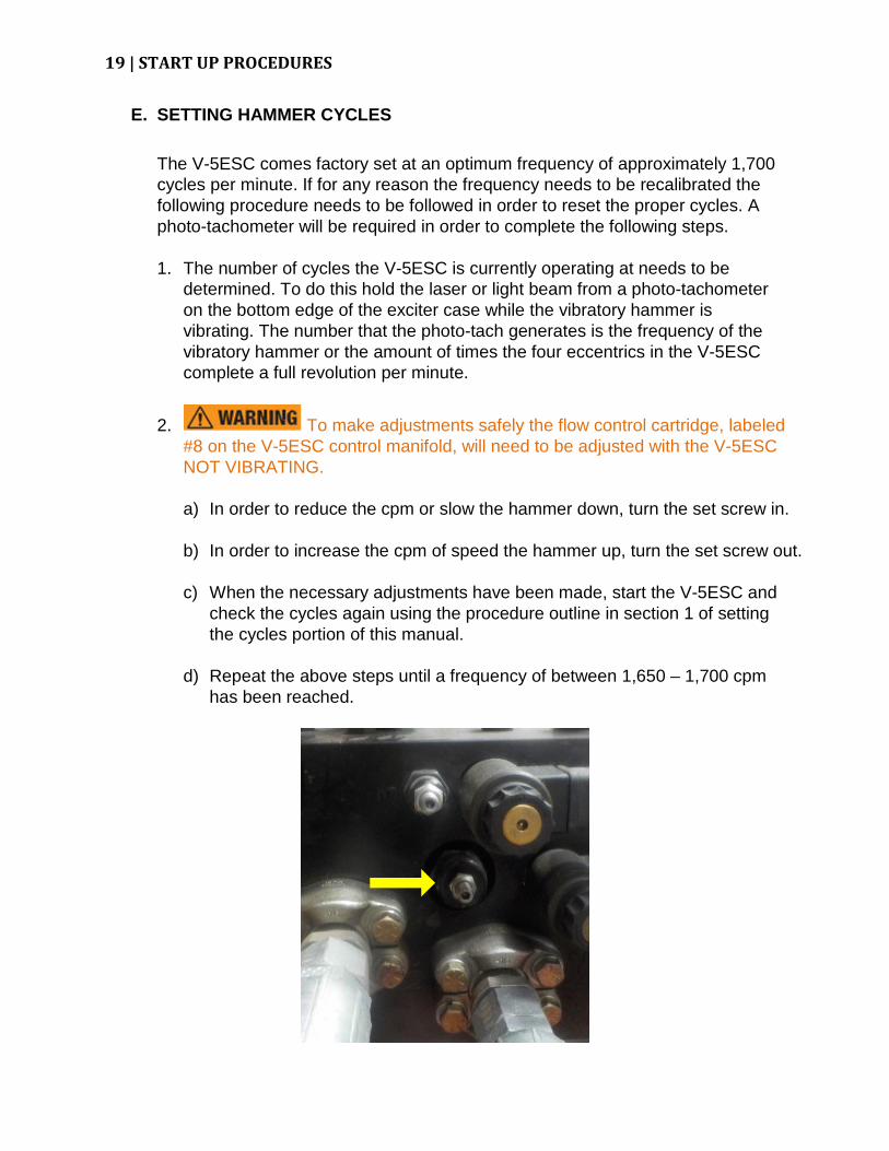
E. SETTING HAMMER CYCLES
The V-5ESC comes factory set at an optimum frequency of approximately 1,700 cycles per minute. If for any reason the frequency needs to be recalibrated the following procedure needs to be followed in order to reset the proper cycles. A photo-tachometer will be required in order to complete the following steps.
1. The number of cycles the V-5ESC is currently operating at needs to be
determined. To do this hold the laser or light beam from a photo-tachometer on the bottom edge of the exciter case while the vibratory hammer is vibrating. The number that the photo-tach generates is the frequency of the vibratory hammer or the amount of times the four eccentrics in the V-5ESC complete a full revolution per minute.
2. To make adjustments safely the flow control cartridge, labeled #8 on the V-5ESC control manifold, will need to be adjusted with the V-5ESC NOT VIBRATING. a) In order to reduce the cpm or slow the hammer down, turn the set screw in. b) In order to increase the cpm of speed the hammer up, turn the set screw out.
c) When the necessary adjustments have been made, start the V-5ESC and
check the cycles again using the procedure outline in section 1 of setting the cycles portion of this manual.
d) Repeat the above steps until a frequency of between 1,650 – 1,700 cpm has been reached.

OPERATING INSTRUCTIONS | 20
VII. OPERATING INSTRUCTIONS
DRIVING MODE
A. OPERATING THE V-5ESC SYSTEM - DRIVING MODE
1. First, check that the lifting capacity of the excavator, at the working radius, exceeds the combined weight of the V-5ESC assembly and the pile. Then, lift the pile using an appropriately sized cable between the lifting point on the Rototilt assembly and the lifting hole in the pile. (Refer to figures 1 and 2). Once the pile is hanging nearly vertical, guide it into the hammer jaws or thread the pile into an already driven pile. Position the jaws on the pile (see figure 2) and close the jaws and start the hammer. The vibration, coupled with the down crowd force of the excavator drives the pile. Do not exceed the down crowd force rating.
Always use the pile handling/ safety cable to attach the pile to the hammer.
2. Cut pile handling holes 2ft. or more above center of the pile on either side of center as required to position pile in jaws as shown in figure 1.
3. The worksite needs to be level to maximize the speed of handling and driving the
pile.
4. As soon as headroom allows, move the pile to the bottom clamp to maximize driving speed.
5. The side clamp jaws are intended to be used to start and drive the pile in soft driving conditions. For best results and longer hammer life, the bottom clamp should be used whenever possible. When using the side clamps, line pull should be limited to 15 tons and crowd force limited to 15 tons. If the side clamp jaws slip on the pile stop the hammer and move to the bottom clamp.
6. Do not start hammer with jaws open. The V-5ESC will vibrate with the jaws open or closed.
FIGURE 1

21 | OPERTING INSTRUCTIONS
7. Always maintain proper vertical alignment between the suspension and pile when driving or pulling the pile.
8. Occasionally the inability of the V-5ESC hammer to continue to move a pile will be the result of the pile striking an impenetrable soil material or an obstruction. The observable action of the V-5ESC hammer and clamped pile will be to note a considerable fall-off of drive pressure and the exciter will “dance” in place often causing erratic interaction of the V-5ESC exciter and its suspension assembly. If the V-5ESC is mounted to an excavator or backhoe do not apply more crowd force than the maximum recommended.
Whenever the V-5ESC hammer is observed “dancing or chattering” in place, it should be hoisted until the action stops. Failure to move a pile with the hammer “dancing or chattering” should be cause to promptly abandon the effort before serious damage is done to the hammer. To continue operations the obstruction must be removed or penetrated by switching to another driving system such as a larger vibro or a MKT diesel or air pile hammer.
For each lift, the operator must review the excavator lifting capacity to determine that the weight of the V-5ESC/Rototilt assembly plus the load being lifted is within the rated capacity of the excavator
Keep hands clear of all three clamps at all times.
Leave the pile safety cable attached to the pile at all times that the pile is not stuck securely in the ground.
The V-5ESC side clamp attachment is designed to handle a single pile with a MAXIMUM weight of 2 TONS. Appropriate pile lifting rigging should be supplied by the end user to handle the pile in a safe manner. Attach cable(s) to lifting eye(s) on the hammer to allow safe handling of the pile and placing it in the jaws as shown in figure 2.
FIGURE 2
OPERATING INSTRUCTIONS | 22
EXTRACTING MODE
B. OPERATING THE V-5ESC SYSTEM – EXTRACTING MODE
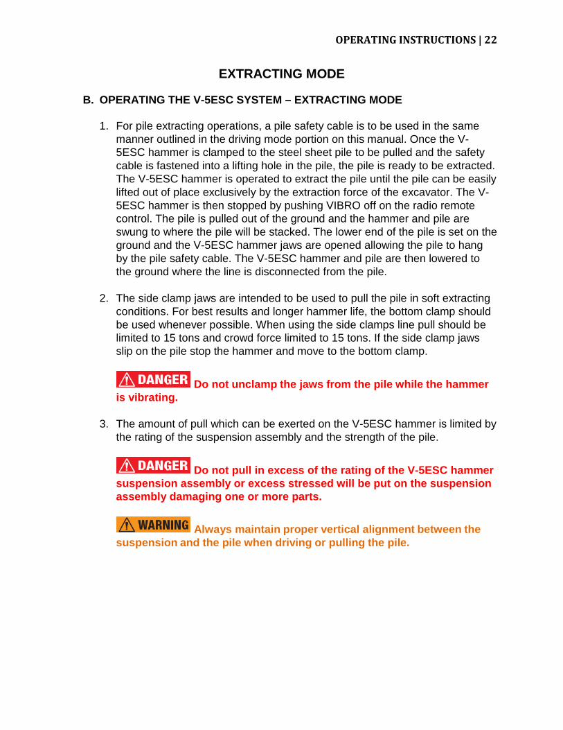
1. For pile extracting operations, a pile safety cable is to be used in the same manner outlined in the driving mode portion on this manual. Once the V-5ESC hammer is clamped to the steel sheet pile to be pulled and the safety cable is fastened into a lifting hole in the pile, the pile is ready to be extracted. The V-5ESC hammer is operated to extract the pile until the pile can be easily lifted out of place exclusively by the extraction force of the excavator. The V-5ESC hammer is then stopped by pushing VIBRO off on the radio remote control. The pile is pulled out of the ground and the hammer and pile are swung to where the pile will be stacked. The lower end of the pile is set on the ground and the V-5ESC hammer jaws are opened allowing the pile to hang by the pile safety cable. The V-5ESC hammer and pile are then lowered to the ground where the line is disconnected from the pile.
2. The side clamp jaws are intended to be used to pull the pile in soft extracting conditions. For best results and longer hammer life, the bottom clamp should be used whenever possible. When using the side clamps line pull should be limited to 15 tons and crowd force limited to 15 tons. If the side clamp jaws slip on the pile stop the hammer and move to the bottom clamp.
Do not unclamp the jaws from the pile while the hammer is vibrating.
3. The amount of pull which can be exerted on the V-5ESC hammer is limited by the rating of the suspension assembly and the strength of the pile.
Do not pull in excess of the rating of the V-5ESC hammer suspension assembly or excess stressed will be put on the suspension assembly damaging one or more parts.
Always maintain proper vertical alignment between the suspension and the pile when driving or pulling the pile.
23 | OPERTING INSTRUCTIONS
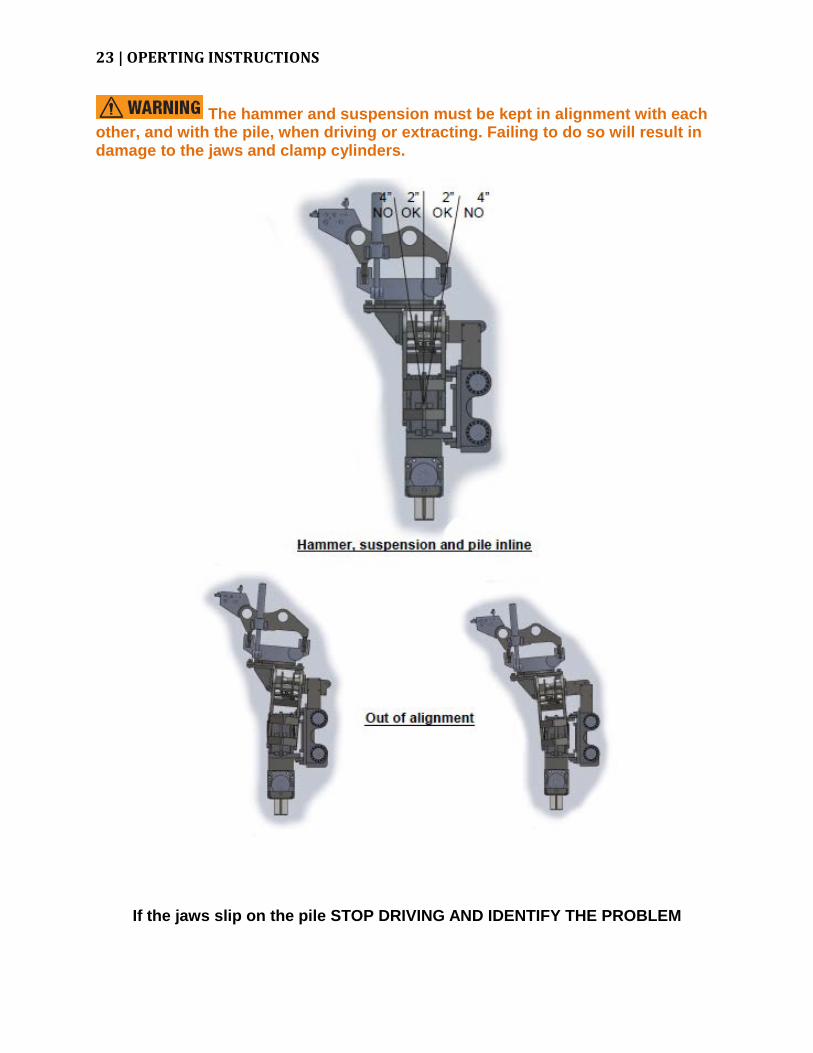
The hammer and suspension must be kept in alignment with each other, and with the pile, when driving or extracting. Failing to do so will result in damage to the jaws and clamp cylinders.
If the jaws slip on the pile STOP DRIVING AND IDENTIFY THE PROBLEM

MAINTENANCE AND SERVICE INSTRUCTIONS | 24
VIII. MAINTENANCE AND SERVICE INSTRUCTIONS
A. The V-5ESC hammer should be inspected regularly to help keep it in good operating condition. The time interval between necessary adjustments and repairs depends primarily on how much and how hard the machine has been used. Repair or replace broken or damaged parts as soon as they are discovered. Periodic cleaning and repainting will help keep all parts in better working order and prolong the machine’s life.
B. Properly maintaining the total V-5ESC system begins with cleanliness; assuring
that no dirt or foreign material enters the hydraulic fluid circuit. Contamination of the components of the hydraulic system pumps, motors, valves, etc., will result in erratic operation, down-time, shortened equipment life, damaged parts and expensive repair or replacement parts costs.
C. The hydraulic fluid level in the system should be maintained at all times. Leaks in
the hydraulic system, particularly noticeable after transport and re-set-up of this system, should be eliminated by checking, tightening or replacing leaking parts. Hose connections may leak as a result of manipulating and straightening the lines and should be promptly tightened. THE CAUSE OF HYDRAULIC LEAKS WHICH CANNOT BE CORRECTED SHOULD BE ELIMINATED BY CALLING FOR FACTORY AUTHORIZED DISTRIBUTOR SERVICE ASSISTANCE.
1. In normal, safe operation of the V-5ESC system, the hydraulic fluid
temperature should remain in its normal range of 115 degrees Fahrenheit to 165 degrees Fahrenheit. The temperature can be read on the thermometer which is integral to the reservoir fluid level gauge. IF THE HYDRAULIC OIL TEMPERATURE BECOMES EXCESSIVE (ABOVE 180 DEGREES FAHRENHEIT), STOP OPERATIONS AND CONSULT WITH THE NEAREST FACTORY AUTHORIZED SERVICING DISTRIBUTOR.
D. Daily check all hoses for cuts or other damage. Hoses are sometimes cut or
bruised by dragging them across the pile heads while setting the V-5ESC hammer. Stop V-5ESC hammer operations that may damage hoses and redirect hoses to avoid dragging and damage. Damaged hose sections must be replaced to eliminate failure and down-time during operations.
E. Inspect the V-5ESC hammer for normal hanging posture and tightened fasteners,
particularly on the suspension and clamp assemblies before and during operation.
STAND AWAY FROM THE PILE AND FROM BELOW THE V-5ESC HAMMER DURING VIBRATING OPERATIONS. ANY UNOBSERVED, UNCORRECTED, LOOSE NUT OR OTHER FASTENER MAY FALL.

25 | MAINTENANCE AND SERVICE INSTRUCTIONS
F. Assure that the proper lube oil level is maintained in the V-5ESC exciter case. If the level of oil is above the sight gauge or the lube oil volume is increasing, this will indicate that the hydraulic motor is leaking hydraulic fluid through the motor drive shaft seal. The seal leakage must be corrected immediately. Exciter lube oil must be changed if seal failure occurs.
G. The V-5ESC system normally the hammer lines and components filled with
hydraulic fluid. Whenever the system has been completely or partially drained (as when a new hose section is replaced), the hydraulic lines must be purged of air. To purge the clamp lines, bleed the bottom and side clamp cylinders using the process outlined above in the system start-up portion of this manual
H. Daily Maintenance Check Lists - Check the entire unit prior to and during start-up
each shift.
1. Prior to starting the V-5ESC at each shift, check as follows:
a) Visually check all hoses for signs of damage or cuts that might cause hose failure during operation. Be sure all connections are tight, especially the quick disconnects.
b) Look for any damage to the unit, in general that might cause it to fail when
put into operation.
c) Check the V-5ESC exciter case lube oil level. With exciter cold, lube level should be just below the top of the sight glass.
d) Check the V-5ESC clamping jaws for excessive wear, cracks or loose fasteners. If it is necessary, the removal of the movable jaw is done by pushing out the 3/4” roll pin either up or down. The single vertical roll pin captivates the movable jaw. The fixed jaw is held tight against the housing with two one-inch bolts. Also, operating the V-5ESC on piling without the Jaw Shields could result in jaw damage if the hammer is dropped onto the pile.

MAINTENANCE AND SERVICE INSTRUCTIONS | 26
2. After start up and the V-5ESC is vibrating, check as follows:
a) Inspect the hydraulic lines for leaks.
b) Allow hydraulic oil temperature to come up slightly above the oil pour temperature, preferable to 50 degrees Fahrenheit before starting the hammer.
c) Before attaching to pile, open and close clamp jaws to verify fast and positive action.
d) Be sure that there are no kinks in the lines and that they hang uniformly.
e) Always maintain a close check on the pile safety cable to assure no
fraying has occurred.
f) Check for overheated bearing housings. Please refer below to item 2, Exciter Overheating In Specific Local Areas, in the Service Trouble Shooting portion of this manual for more information what to look for when checking for overheated bearing housings.
I. The V-5ESC exciter case has been filled with the proper fluid at the factory. Use
the following list for adding fluids which are compatible with those used at the factory:
1. V-5ESC ExciterLube Oil
Shell Omala RL 220 Synthetic ......................................... Capacity – 8 Gallons
a) Change after every 50 hours of driving time, sooner if contaminated or discolored.
27 | SERVICE TROUBLE SHOOTING
IX. SERVICE TROUBLE SHOOTING
A. V-5ESC VIBRATORY HAMMER
1. Increase In Exciter Lube Oil Level
This is a sure sign that the hydraulic motor has a shaft seal failure. If submerged under water, water may have seeped into the exciter case.
2. Exciter Overheating In Specific Local Areas
Checking the side covers for the bearings will give an indication of an overheating bearing. This bearing should be checked for excessive binding or wear. Make sure the oil level is correct. It is not unusual for the temperature of the exciter housing to go up to 200 degrees Fahrenheit if the V-5ESC is run at full frequency over a long period of time. Check the lower magnetic plug for metal which might indicate excessive wear of gears or bearings.
3. Internal Noise In Exciter
Unusual noise in exciter generally means something is wrong - either a bearing is starting to fail, gear train restriction, or a hydraulic motor problem causing excessive drive loading. Lube oil level should be checked.
4. V-5ESC Frequency Fluctuation
Frequency is a function of pump flow and motor speed. If the pump flow is not even or a hydraulic motor is failing, it is possible the frequency will not be constant especially as the load goes a little higher (before going over relief). Check for exciter hotspots which may indicate a bearing is failing.
5. Erratic Suspension Movement
High blow count soil conditions or underground obstructions may cause the hammer energy to rebound into the suspension and affect the suspension isolation. The suspension will bounce out of sync with the frequency, which will eventually cause the elastomers to overheat and fail.
6. Slow Clamp Movement
Generally, slow clamping is caused by air in the hydraulic hoses. Bleed both clamp close and clamp open bleeders of the bottom and side clamp cylinders using the process outlined above in the system start-up portion of this manual.

SERVICE TROUBLE SHOOTING | 28
7. Jaws Slipping on Pile
a) If jaws are worn too much there may be a lack of clamping jaw travel. The clamp jaw travel is two and one half inches.
b) Check clamping pressure.
c) Air may be in the clamp line requiring cylinder bleeding using the process outlined above in the system start-up portion of this manual.
8. No Vibration But Drive Pressure at 3500 PSI When Put In Vibrate Mode
Assuming the drive hoses are not blocked and are connected fully and correctly, there may be a locked bearing, gear, or motor.
9. V-5ESC Not Coming Up To Speed And/Or Pressure Very Low
Relief valve in the directional control valve may be clogged. The system may have a worn out motor.
10. V-5ESC Frequency Low But Pressure High
The motor seal might have blown filling the V-5ESC Exciter Case with oil. Check the lube oil level. The exciter case may have a bearing failure. Check for excessive exciter case heat.
This information is included for the user to have a point of reference while discussing trouble shooting actions with his factory authorized distributor’s service department. Call your nearest MKT factory authorized distributor’s service department to remedy any abnormal occurrences in the operation of your V-5ESC system. Successful internal repairs and general overhaul of a V-5ESC hydraulic vibratory pile driver/extractor system must be handled as a clean shop procedure. MKT factory authorized distributors are properly equipped and should be contacted to provide such service. For the name and address of the nearest MKT factory authorized distributor call MKT Manufacturing Inc., St. Louis, Missouri at 314/388-2254

29 | DRAWING AND PARTS LISTS
X. DRAWING AND PARTS LISTS This manual includes the following Drawings and Parts Lists:
A. V-5Esc GENERAL ASSEMBLY AND PARTS LIST
B. EXCITER CASE ASSEMBLY
C. ECCENTRIC SHAFT ASSEMBLY AND PARTS LIST
D. MOTOR SHAFT ASSEMBLY AND PARTS LIST
E. V-5Esc HYDRAULIC CLAMP ASSEMBLY AND PARTS LIST
F. SIDE CLAMP ASSEMBLY
G. ROTOTILT ASSEMBLY
H. MANIFOLD ASSEMBLY
I. V-5Esc HYDRAULIC SCHEMATIC AND PARTS LIST
J. ELECTRICAL SCHEMATIC

DRAWING AND PARTS LISTS | 30
V-5ESC GENERAL ASSEMBLY

31 | DRAWING AND PARTS LISTS
V-5ESC GENERAL ASSEMBLY
ITEM NO.
MKT PART NUMBER DESCRIPTION QTY.
1 Exciter Assembly V-5ESC EXCITER CASE ASSEMBLY 1 2 4051203 SUSPENSION HOUSING 1 3 9410014 ELASTOMER SHEAR BLOCK 8 4 9015925 HEX HEAD CAP SCREW 3/4-10 x 3" 16 5 9030610 LOCK WASHER 3/4" 58 6 9005007 HEX NUT 3/4-10 52 7 9015923 HEX HEAD CAP SCREW 3/4-10 x 2-3/4" 32 8 4051260 V-5ESC CLAMP ASSEMBLY ROUND JAWS 1 9 9016311 HEX HEAD CAP SCREW 1-1/2-6 x 3-1/4" 6
10 4050341 BACK UP PLATE 1 11 4050273 HOSE BLOCK 1 12 9020003 FLAT WASHER 1/2" 4 13 9015735 HEX HEAD CAP SCREW 1/2-13 x 5" 4 14 9030608 LOCK WASHER 1/2" 18 15 9015717 HEX HEAD CAP SCREW 1/2-13 x 2" 2 16 9015713 HEX HEAD CAP SCREW 1/2-13 x 1-1/2" 4 17 9230947 HYDRAULIC ADAPTER 2700-LN-16 2 18 9230949 HYDRAULIC ADAPTER 2704-LN-12-12-12 2 19 9231153 HYDRAULIC ADAPTER 2406-12-6 4 20 9231195 HYDRAULIC ADAPTER 2700-LN-12 1 21 4051253 SIDE CLAMP ASSEMBLY 1 22 9030612 LOCKWASHER 1" 20 23 9016117 HEX HEAD CAP SCREW 1-8 x 3" 20 24 4051266 RUBBER MOUNT SIDE CLAMP V-5ESC 1 25 9015929 HEX HEAD CAP SCREW 3/4-10 x 3.5" 4 26 9410033 SHEAR BLOCK 2 27 9015711 HEX HEAD CAP SCREW 1/2-13 x 1-1/4" 8 28 9015719 HEX HEAD CAP SCREW 1/2-13 x 2-1/4" 4 29 9005005 HEX NUT 1/2-13 4 30 4950619 V-5ESC ROTOTILT BRACKET 1 31 9231337 HYDRAULIC ADAPTER 2701-LN-16-16 2 32 9231338 HYDRAULIC ADAPTER 2701-LN-12-12 1 33 9030616 LOCKWASHER 1-1/2" 10 34 9016313 HEX HEAD CAP SCREW 1-1/2-6 x 3-1/2" 10 35 4051238 ROTOTILT ASSEMBLY 1 36 9030614 LOCKWASHER 1-1/4" 3 37 9016221 HEX HEAD CAP SCREW 1-1/4-6 x 3-1/2" 3 38 4051239 MANIFOLD ASSEMBLY 1 39 9015917 HEX HEAD CAP SCREW 3/4-10 x 2" 6
DRAWING AND PARTS LISTS | 32
V-5ESC GENERAL ASSEMBLY
ITEM NO.
MKT PART NUMBER DESCRIPTION QTY.
40 4051226 HYD. HOSE ASSEMBLY - MOTOR LINES 2 41 4051227 HYD. HOSE ASSEMBLY - DRAIN LINE 1 42 4051228 HYD. HOSE ASSEMBLY - CLAMP LINES 2 43 4201014 NAMEPLATE, SHELL OMALA RL 220 1 44 4050102 NAMEPLATE, LUBE FILL 1 45 4050100 NAMEPLATE, LUBE LEVEL 1 46 4990213 NAMEPLATE, MODEL & SERIAL NUMBER 1 47 990600 DECAL, EAR PROTECTION 1 48 4950645 JUNCTION BOX, ROTOTILT 1 49 4950628 WIRELESS CONTROL ASSEMBLY & REMOTE 1 50 4950641 ELE. CONTROL, WIRED PENDANT (OPTIONAL) 1

33 | DRAWING AND PARTS LISTS
V-5ESC EXCITER CASE ASSEMBLY

DRAWING AND PARTS LISTS | 34
V-5ESC EXCITER CASE ASSEMBLY
ITEM NO.
MKT PART NUMBER DESCRIPTION QTY.
1 4051202 EXCITER MACHINING 1 2 4201005 ECCENTRIC SHAFT ASSEMBLY 1 3 4201006 ECCENTRIC SHAFT ASSEMBLY 1 4 4300013 SHAFT, ECCENTRIC 2 5 4300041 KEY, ECCENTRIC 2 6 4300042 GASKET, BEARING COVER 4 7 9140106 BEARING, ECCENTRIC 4 8 4300117 BEARING COVER 4 9 9050507 SOCKET HEAD CAP SCREW 3/8-16 x 3/4" 24 10 4050340 PINION & SHAFT 1 11 9140107 BEARING, PINION 2 12 4300022 GASKET, PINION 1 13 4300136 COVER, MOTOR SHAFT 1 14 9050505 SOCKET HEAD CAP SCREW 3/8-16 x 5/8" 6 15 4050300 GASKET, HYDRAULIC MOTOR 1 16 9100069 HYDRAULIC MOTOR 1 17 9030610 LOCKWASHER 3/4" 14 18 9015917 HEX HEAD CAP SCREW 3/4-10 x 2" 4 19 4051105 COVER, EXCITER V5E 1 20 9030609 LOCKWASHER 5/8" 24 21 9015813 HEX HEAD CAP SCREW 5/8-11 x 1-1/2" 24 22 4020207 FILL PLUG 1 23 9420011 RELIEF FITTING 1 24 4160121 MOTOR GUARD SUPPORT BLOCK 2 25 4051107 MOTOR GUARD 1 26 9015913 HEX HEAD CAP SCREW 3/4-10 x 1-1/2" 10 27 9310479 SIGHT GLASS 1 28 9310002 MAGNETIC PLUG 2 29 9230998 SPLIT FLANGE ADAPTER KIT 2 30 9231208 HYDRAULIC ADAPTER 6405-10-4 1 31 4050283 DRAIN RELIEF 1 32 9230588 HYDRAULIC ADAPTER 6400-8-10 1

35 | DRAWING AND PARTS LISTS
V-5ESC ECCENTRIC SHAFT ASSEMBLY (420 10 05/06)

DRAWING AND PARTS LISTS | 36
V-5ESC ECCENTRIC SHAFT ASSEMBLY (420 10 05/06)
ITEM NO.
MKT PART NUMBER DESCRIPTION QTY.
1 4160153 ECCENTRIC GEAR 1 2 4160153 ECCENTRIC GEAR 1 3 4300041 ECCENTRIC KEY 1 4 4300013 ECCENTRIC SHAFT 1 5 4300117 BEARING COVER 2 6 9140106 CYLINDERICAL ROLLER BEARING 2 7 4300042 GASKET, BEARING COVER 2 8 9050507 SOCKET HEAD CAP SCREW 3/8-16 x 3/4" 12 9 4300043 PIN 1 10 9050915 SOCKET HEAD CAP SCREW 3/4-10 x 1-3/4" 4 11 4160155 ECCETNRIC 1

37 | DRAWING AND PARTS LISTS
V-5ESC MOTOR SHAFT ASSEMBLY

DRAWING AND PARTS LISTS | 38
V-5ESC MOTOR SHAFT ASSEMBLY
ITEM NO.
MKT PART NUMBER DESCRIPTION QTY.
1 4300136 MOTOR SHAFT COVER 1 2 9050505 SOCKET HEAD CAP SCREW 3/8-16 x 5/8" 6 3 4300022 GASKET, MOTOR BEARING COVER 1 4 9140107 BEARING 2 5 4050340 PINION 1 6 4050300 GASKET, HYDRAULIC MOTOR 1 7 9015917 HEX HEAD CAP SCREW 3/4-10 x 2" 4 8 9030610 LOCKWASHER 3/4" 12 9 9100069 HYDRUALIC MOTOR 1 10 9230998 SPLIT FLANGE ADAPTER KIT 2 11 9230588 HYDRAULIC ADAPTER 6400-8-10 1 12 9231208 HYDRAULIC ADAPTER 6405-10-4 1 13 4050283 DRAIN RELIEF 1

39 | DRAWING AND PARTS LISTS
BOTTOM CLAMP ROUND JAWS (405 12 60)

DRAWING AND PARTS LISTS | 40
BOTTOM CLAMP ROUND JAWS ( 405 12 50)
ITEM NO.
MKT PART NUMBER DESCRIPTION QTY.
1 4050307 CLAMP HOUSING 1 2 4160131 HYDRAULIC CYLINDER 1 3 4950063 CLAMP SLIDE 1 4 4200138 PIN, CLAMP SLIDE 1 5 9016218 HEX HEAD CAP SCREW 1 1/4-12 x 3" 6 6 4050358 CYLINDER GUARD 1 7 9016224 HEX HEAD CAP SCREW 1 1/4-12 x 4" 2 8 9030610 LOCKWASHER 3/4" 12 9 9015917 HEX HEAD CAP SCREW 3/4-10 x 2" 12
10 9020107 FLAT WASHER 1" 2 11 9016101 HEX HEAD CAP SCREW 1-8 x 1" 2 12 4950062 MOVABLE JAW 1 13 9240055 SPIROL PIN 1 14 4950649 ADAPTER BLOCK 1 15 4950648 MODIFIED CAISSON JAW 1 16 9240072 SPIROL PIN 1 17 9030612 LOCKWASHER 1" 2 18 9016137 HEX HEAD CAP SCREW 1-8 x 7" 2 19 4050134 JAW SHIELD 1 20 4051254 JAW SHIELD V-5ESC 1 21 9420004 GREASE FITTING 1 22 9230223 HYDRAULIC ADAPTER 2501-8-12 1 23 9231123 HYDRAULIC ADAPTER 2503-8-12 1 24 9380081 SAFETY CABLE 1 25 9380082 SWEDGE CLAMP 2

41 | DRAWING AND PARTS LISTS
CLAMP BLEEDING PROCEDURE
Whenever the hydraulic line of the V-5ESC system have been disconnected then reconnected for any reason the two side clamp cylinders and bottom clamp cylinder must be bled of entrained air. In order to effectively bleed all entrained air from the system the hammer must be in the vertical, upright position.
Contents of hydraulic components may be under pressure and extreme care should be taken when opening or bleeding components.
Follow the instructions found in the start-up portion of this manual (pg. 17) to operate the clamp functions. Close the jaws and hold the clamp close function while you open the bleeder on the back of the bottom clamp.
Do not back vent screw all the way out! Allow oil to vent approximately 30 seconds or until an air free stream of oil comes from each vent screw.

DRAWING AND PARTS LISTS | 42
SIDE CLAMP ASSEMBLY (405 12 53)

43 | DRAWING AND PARTS LISTS
SIDE CLAMP ASSEMBLY (405 12 53)
ITEM NO.
MKT PART NUMBER DESCRIPTION QTY.
1 4051252 SIDE CLAMP MACHINING 1 2 4051249 RUBBER MOUNT 2 3 4051264 GUSSET 2 4 4051237 GUARD - SIDE CLAMP 2 5 4950638 HYDRAULIC CYLINDER 2 6 9050723 SOCKET HEAD CAP SCREW 1/2-13 x 2-3/4" 32 7 4950598 JAW 4 8 9240072 SPIROL PIN 4 9 9231156 HYDRAULIC ADAPTER 6803-6-6-6 2
10 9231275 HYDRAULIC ADAPTER 6410-6-6 2 11 9230912 HYDRAULIC ADAPTER 6801-6-6 2 12 9430421 HOSE CLAMP (-6) 6 13 9030606 LOCKWASHER 3/8" 3 14 9015511 HEX HEAD CAP SCREW 3/8-16 x 1" 1 15 9015513 HEX HEAD CAP SCREW 3/8-16 x 1-1/4" 2 16 9015513 HEX NUT 3/8-16 2 17 4051230 HYD. HOSE ASSEMBLY 2 18 4051229 HYD. HOSE ASSEMBLY 2 19 8100011 STICKER KIT – SIDE CLAMP 1

DRAWING AND PARTS LISTS | 44
CLAMP BLEEDING PROCEDURE
Whenever the hydraulic line of the V-5ESC system have been disconnected then reconnected for any reason the two side clamp cylinders and bottom clamp cylinder must be bled of entrained air. In order to effectively bleed all entrained air from the system the hammer must be in the vertical, upright position.
Contents of hydraulic components may be under pressure and extreme care should be taken when opening or bleeding components.
Follow the instructions found in the start-up portion of this manual (pg. 17) to operate the clamp functions. Close the jaws and hold the clamp close function while you open the bleeder on the back of the bottom clamp.
Do not back vent screw all the way out! Allow oil to vent approximately 30 seconds or until an air free stream of oil comes from each vent screw.
BOTTOM 1st TOP 2nd

45 | DRAWING AND PARTS LISTS
ROTOTILT ASSEMBLY (405 12 38)

DRAWING AND PARTS LISTS | 46
ROTOTILT ASSEMBLY (4051238)
ITEM NO.
MKT PART NUMBER DESCRIPTION QTY.
1 9220135 ROTOTILT 1 2 4950639 ADAPTER PLATE-RT80 1 3 4950667 HYDRAULIC MOTOR 1 4 9500009 FLAT WASHER M16 28 5 9500136 SOCKET HEAD CAP SCREW M16x2.0 x 260MM 28 6 9500310 DISC LOCKWASHER 29 7 9500215 HEX NUT M16x2.0 28 8 4950678 ESC MANIFOLD MOUNT 1 9 9500146 SOCKET HEAD CAP SCREW M12x1.75 x 80MM 8
10 9030610 LOCKWASHER 3/4" 6 11 9015921 HEX HEAD CAP SCREW 3/4-10 x 2-1/2" 4 12 9015919 HEX HEAD CAP SCREW 3/4-10 x 2-1/4" 2 13 9231408 HYDRAULIC ADAPTER 3800-6-8 2 14 4020614 HYD. HOSE ASSEMBLY 2 15 4300508 ROTOTILT GREASE LINE 1 16 1170190 CASE DRAIN LINE - ROTOTILT MOTOR 1 17 1170232 BANJO SCREW 2 18 1170240 COPPER WASHER 4 19 9231339 HYDRAULIC ADAPTER 3859-6-6-6 1 20 9231293 HYDRAULIC ADAPTER 3801-6-6 2 21 4110022 NAMERPLATE - CLAMP OPEN 1 22 4110023 NAMEPLATE - CLAMP CLOSE 1

47 | DRAWING AND PARTS LISTS
MANIFOLD VALVE ASSEMBLY (405 12 39)

DRAWING AND PARTS LISTS | 48
V-5ESC MANIFOLD ASSEMBLY (405 12 39)
ITEM NO.
MKT PART NUMBER DESCRIPTION QTY.
1 4950634 MANIFOLD VALVE 1 2 9230194 HYDRAULIC ADAPTER 6801-8-8 2 3 9231149 CAP NUT 304-C-4 3 4 9231316 HYDRAULIC ADAPTER 6804-4-4-4 1 5 9230314 HYDRAULIC ADAPTER 6400-20-20 2 6 9230013 CAP NUT 304-C-20 2 7 9230012 CAP NUT 304-C-12 1 8 9231077 HYDRAULIC ADAPTER 6400-4-6 2 9 9230096 HYDRAULIC ADAPTER 6400-12-12 2
10 9230998 SPLIT FLANGE ADAPTER KIT 2 11 4051247 HYD. HOSE ASSEMBLY 1 12 4051270 HYD. HOSE ASSEMBLY 2

49 | DRAWING AND PARTS LISTS
V-5ESC MANIFOLD COMPONENTS (495 06 34)

DRAWING AND PARTS LISTS | 50
V-5ESC MANIFOLD COMPONENTS (495 06 34)
51 | DRAWING AND PARTS LISTS
V-5ESC MANIFOLD COMPONENTS (495 06 34)
ITEM NO.
MKT PART NUMBER DESCRIPTION QTY.
1 174-399 MANIFOLD BODY 1 2 9310835 RELIEF VALVE 1 3 9310836 RELIEF VALVE 1 4 9310837 MODULATING VALVE 1 5 9310838 CHECK VALVE 1 6 9310839 CHECK VALVE 2 7 9310840 CHECK VALVE 1 8 9310863 NEEDLE VALVE 1 9 9310841 FLOW CONTROL 1
10 9310842 FLOW CONTROL 1 11 9310843 DIRECTIONAL VALVE 1 12 9310844 DIRECTIONAL SPOOL VALVE 1 13 9310845 DIRECTIONAL SPOOL VALVE 1 14 9310856 RELIEF VALVE 1 15 9310872 CHECK VALVE 1 16 9310724 CHECK VALVE 1

DRAWING AND PARTS LISTS | 52
V-5ESC HYDRAULIC SCHEMATIC AND PARTS LIST

53 | DRAWING AND PARTS LISTS
V-5ESC HYDRAULIC SCHEMATIC AND PARTS LIST

DRAWING AND PARTS LISTS | 54
V-5ESC HYDRAULIC SCHEMATIC AND PARTS LIST
ITEM NO.
MKT PART NUMBER DESCRIPTION QTY.
1 4051272 HYD. HOSE ASSEMBLY 2 2 4051242 HYD. HOSE ASSEMBLY 1 3 4051243 HYD. HOSE ASSEMBLY 2 4 4051244 HYD. HOSE ASSEMBLY 1 5 4051245 HYD. HOSE ASSEMBLY 2 6 4051246 HYD. HOSE ASSEMBLY 1 7 4051247 HYD. HOSE ASSEMBLY 1 8 4051270 HYD. HOSE ASSEMBLY 2 9 4051226 HYD. HOSE ASSEMBLY 2 10 4051227 HYD. HOSE ASSEMBLY 1 11 4051228 HYD. HOSE ASSEMBLY 2 12 4051230 HYD. HOSE ASSEMBLY 2 13 4051229 HYD. HOSE ASSEMBLY 2 14 4020614 HYD. HOSE ASSEMBLY 2 15 9310875 HIGH PRESSURE SWIVEL 1 16 9310874 HIGH PRESSURE SWIVEL 2 17 9100069 HYDRAULIC MOTOR 1 18 4160131 HYDRAULIC CYLINDER 1 19 4950638 HYDRAULIC CYLINDER 2 20 4051239 V-5ESC MANIFOLD ASSEMBLY 1

55 | DRAWING AND PARTS LISTS

DRAWING AND PARTS LISTS | 56