manufacturing and design analysis on cad cam … design consideration of die casting material of...
TRANSCRIPT
International Research Journal of Engineering and Technology (IRJET) e-ISSN: 2395 -0056
Volume: 02 Issue: 08 | Nov-2015 www.irjet.net p-ISSN: 2395-0072
© 2015, IRJET ISO 9001:2008 Certified Journal Page 1627
Manufacturing and Design Analysis on CAD CAM Software for Single
Cavity PDC Die
Venkat Raman Sao, Ashish Khandelwal, Chitrakant Tiger
Mr. Venkat Raman Sao,Department of Mechanical, College-CEC/CSVTU University,Chhattisgarh, India Prof. Ashish Khandelwal,Department of Mechanical, College-CEC/CSVTU University, Chhattisgarh, India Prof. Chitrakant Tiger, Department of Mechanical, College-CEC/CSVTU University, Chhattisgarh, India
---------------------------------------------------------------------***---------------------------------------------------------------------
Abstract -Tool design is basically a process of designing a device to get product of desired shape, form, appearance, function etc. In the process the liquid metal is injected into the cavity under external pressure and this pressure is maintained until the liquid metal cools and then the solid casting is ejected out of the cavity. In all organizations before starting the actual production or filling up the tenders, estimation is done. Over estimation leads increase the cost & hence tenders may not get. Under estimation leads to heavy loss to the concern. Hence accurate estimating is very essential. These studies are focused on estimating the cost of single cavity PDC die with respect to time, to reduce the manufacturing lead time. The project gives a brief introduction about the work accomplished in design including the explored applications in Unigraphics & other design related information. This project is basically dependent on pressure die casting. It also gives a view of design consideration involved in Mould & Die casting dies. It gives the idea of flow of project from the stage of receive till dispatch of the tool.
Key Words: Unigraphics
1. INTRODUCTION Ever since man discovered that metals could be melted, he had tried to form these metals into shapes useful to him by pouring the liquid metals into moulds whose shape they retain during and after solidification. The casting of molten metal in moulds is one of the oldest methods developed by man to shape metal objects.These are called mouldings or castings and are classified depending upon the moulding method, mould material or casting process employed. Casting is one of the oldest methods of obtaining parts of required form. It consists of feeding liquid metal to the shaped cavity and allowing it to cool until the liquid metal solidifies. In metal mould casting process, the mould will be metal and hence it will be of permanent character. Where as in other process the mould will be destroyed for each casting produced.
1.1 Pressure Die Casting In this process the liquid metal is injected into the cavity under external pressure and this pressure is maintained until the liquid metal cools and then the solid casting is ejected out of the cavity.
1.2 Design Consideration of Die Casting Material of casting its shrinkage and density of
material to be cast. Type of casting weather sand, hot chamber or
cold chamber & also weather the machine is horizontal or vertical.
Projected area of casting thus weight & tonnage calculations.
If side core then its projected area must be taken into consideration while tonnage calculation.
Selection of parting line. Determine the core & cavity area required. Depending upon size of side core and weight
select actutation method for side core. Proper cooling is essential, for inserts if line
cooling is not sufficient take help of spot cooling.
Core and cavity dimensions must include shrinkage value.
The material of core & cavity must withstand high melting temperature.
While deciding cooling layout care must be taken that water must not enter to core & cavity & also other system.
1.3 Machines All die casting machines have one of two different metal- pumping system:
Hot Chamber Machine

International Research Journal of Engineering and Technology (IRJET) e-ISSN: 2395 -0056
Volume: 02 Issue: 08 | Nov-2015 www.irjet.net p-ISSN: 2395-0072
© 2015, IRJET ISO 9001:2008 Certified Journal Page 1628
Cold Chamber Machine If the metal being cast melts at low temperature and thus does not attack the injection pump material, the pump can be placed directly in the molten metal bath, then a hot chamber machine must be used. If the molten metal attacks the pump material at casting temperature, the pump must not be placed in the molten bath, and a cold chamber machine must be used. 2. PROBLEM IDENTIFICATION Tool design is basically a process of designing a device to get product of desired shape, form, appearance, function etc. In all organizations before starting the actual production or filling up the tendors, estimation is done. Over estimation leads increase the cost & hence tendors may not get. Under estimation leads to heavy loss to the concern. Hence accurate estimating is very essential. These studies are focused on estimating the cost of single cavity PDC die with respect to time, to reduce the manufacturing lead time.
2.1 Process Flow Separator 1: Design Input
* It involves information about all input to the design of tool recorded in DESIGN & DEVELOPMENT INPUT. * Component drawings received from customers, copy of work order, design plans etc are kept in this separator.
Customer gives information to the marketing department regarding their requirement. Before starting the design activities following things should be make clear with the customer. The component related input from the customer may be in the form of
2D Component Drawing 3D Component Model Existing Sample of Component
The tool related input from the customer may be in the form of
Type of Mould/Die. No. of Cavities. Production Rate.
The Material related input from the customer may be in the form of
Component Material Shrinkage Component weight
Die Set Material Core/Cavity Material
Separator 2: Design Output(Stage 1)
GENERAL ASSEMBLY & BOM
In this section general assembly and tentative Bill of Material are kept. These are released to PPC and the copy of same (COPY 1) is maintained in the design department file followed by entering in DESIGN RELEASE NOTE.
Separator 3: Design Review
Design inputs reviewed by design(At Input Stage). Tool design reviewed by design. Tool design reviewed by production, PPC. Reviewed by customer (Optional).
Separator 4: Design Verification In this section the tool so designed is verified for following check points in DESIGN VERIFICATION FORM. The check points are:
The tool/die is suitable to the specified machine. The tool parts can be manufactured/assembled
easily. The tool meets the specified requirements of
customer. Selection of material is suitable for the type of
tool. The acceptance criteria & tool parameters are
clearly defined & documented.
Separator 5: Design Output(Stage 2) In this section final tool drawings are kept and the same are released to 6 sections as below and recorded in DESIGN RELEASE NOTE (STAGE 2).
Copy 1- Design Department Copy 2- PPC(Production Planning & Control) Copy 3- Job Card Copy 4_ Die Maker Copy 5- Assembly Copy 6- Raw Material Copy 7- Store
Separator 6: Design Validation Trial Report

International Research Journal of Engineering and Technology (IRJET) e-ISSN: 2395 -0056
Volume: 02 Issue: 08 | Nov-2015 www.irjet.net p-ISSN: 2395-0072
© 2015, IRJET ISO 9001:2008 Certified Journal Page 1629
The tool so manufactured is tested for its desired function by undergoing trial which may be conducted in house or at customers site.
Any deviation so obtained are noted down in TRIAL REPORT/ QC REPORT and hence incorporated in stage7.
3.METHODOLOGY 3.1 Design Input For Single Cavity PDC Die Component related input Product drawing: Finished drawing available (Casting drawing not available) 3D Model: Available Sample: Available Gate location: As per existing sample (Edge gate) Material: Al alloy Al Si Shrinkage: 0.6% Weight of component: 1682 gms Density of material:- 2.7 gm/cm2
3.2 Component Drawing
Fig 3.1 Top view of component
Fig 3.2 Bottom view of component
Table 3.1
1 Material Aluminium Alloy (AlSi-12)
2 Shrinkage 0.6% 3 Ejection stroke 110mm max. 4 Overall size of mould(H*L*W) 710*546*538 5 Shut height 538 Gate Calculation
1 Weight across gate 2300 gms 2 Minimum wall thickness 4mm 3 Fill time 0.06sec 4 Gate velocity 4000cm/sec2 5 Overflow opening area 100% Die casting machine selection
1 Component name Casting drawing no.
Base-60
2 No. of cavities 01 3 Wt. of (casting + runner biscuit +
overflow)=Shot wt. 3600gms
4 Projected area(casting + runner biscuit + overflow)=total Projected area
684 cm2
5 Recommended sp. Casting pressure
600-700kg/cm2
6 Die opening force(ton) 500 tons 7 Die locking force(ton) 600 tons 8 M/c selected 660T HMT Runner calculation
1 Ratio of runner area to gate area 3:1 2 Ratio of runner thickness to gate
thickness 8:1
3.3 Design Calculation 1.Total projected area of component = 470.00cm2 2.Projected area of side core = 135cm2 3.Total projected area of runner gate = 214cm2 Overflow biscuit 4.Total projected area of component, = 470+214+135 Side core, runner, gate, overflow & = 819cm2 Biscuit 5.Recommended sp. Casting press. = 600-700kg/cm2 6.Die opening force = 819×600 = 491 Tons 7.Die locking force = Die opening Force × 1.2
= 491 × 1.2
International Research Journal of Engineering and Technology (IRJET) e-ISSN: 2395 -0056
Volume: 02 Issue: 08 | Nov-2015 www.irjet.net p-ISSN: 2395-0072
© 2015, IRJET ISO 9001:2008 Certified Journal Page 1630
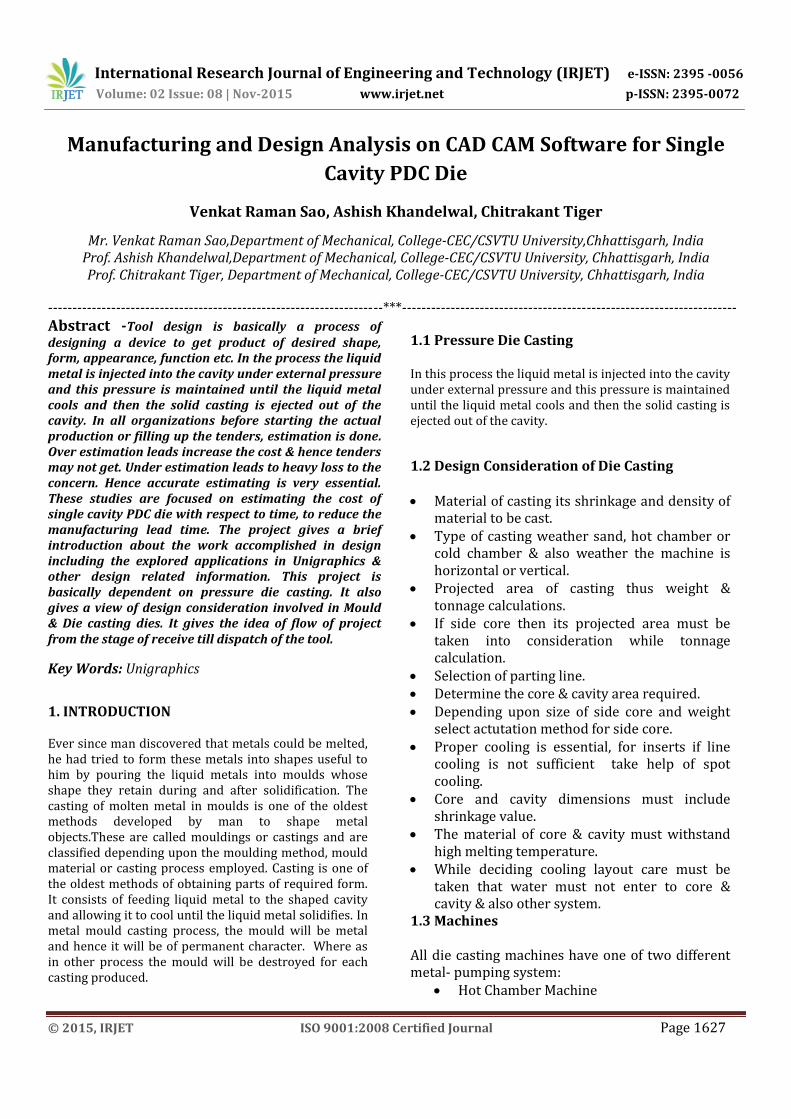
= 590 Tons 8.Weight of component = Vol.×Density = 622.9× 2.7=1682gm Gate Calculations: Gate thickness Hg = t/3 = 4/3 = 1.4mm(1.8mm considered) Vol. of metal through = 1.2× Total vol. of component Gate,Vg = 1.2 × 622.9 = 748cm3 Fill time = 60 millisecond Gate velocity = 40m/s Fill rate, Q = Vol. of metal× 1000/60 Through gate = 748× 1000/60 = 12466.6 cm3/sec Gate area, Ag = Q/100× Vg
= 12466.6/100×40 = 3.05 cm2=305mm2 Length of gate, Lg = (Ag × 100)/Gate thickness = (3.05 × 100)/1.8 = 140mm Runner Calculation: Ratio of runner area : Gate area = 3:1 Ratio of runner thickness : Gate thickness = 8:1 Overflow calculations: Depth of overflow = 3 × Wall thickness = 3 × 1.8 = 5.4 mm Width of overflow = 2 × 5.4 = 10.8mm Length of overflow = 2 × width = 2 × 11 = 22mm
3.4 Part Details
Fig 3.3: Fixed Insert
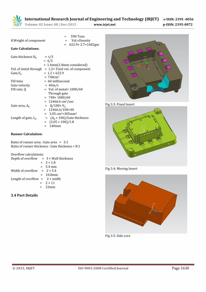
Fig 3.4: Moving Insert
Fig 3.5: Side core
International Research Journal of Engineering and Technology (IRJET) e-ISSN: 2395 -0056
Volume: 02 Issue: 08 | Nov-2015 www.irjet.net p-ISSN: 2395-0072
© 2015, IRJET ISO 9001:2008 Certified Journal Page 1631
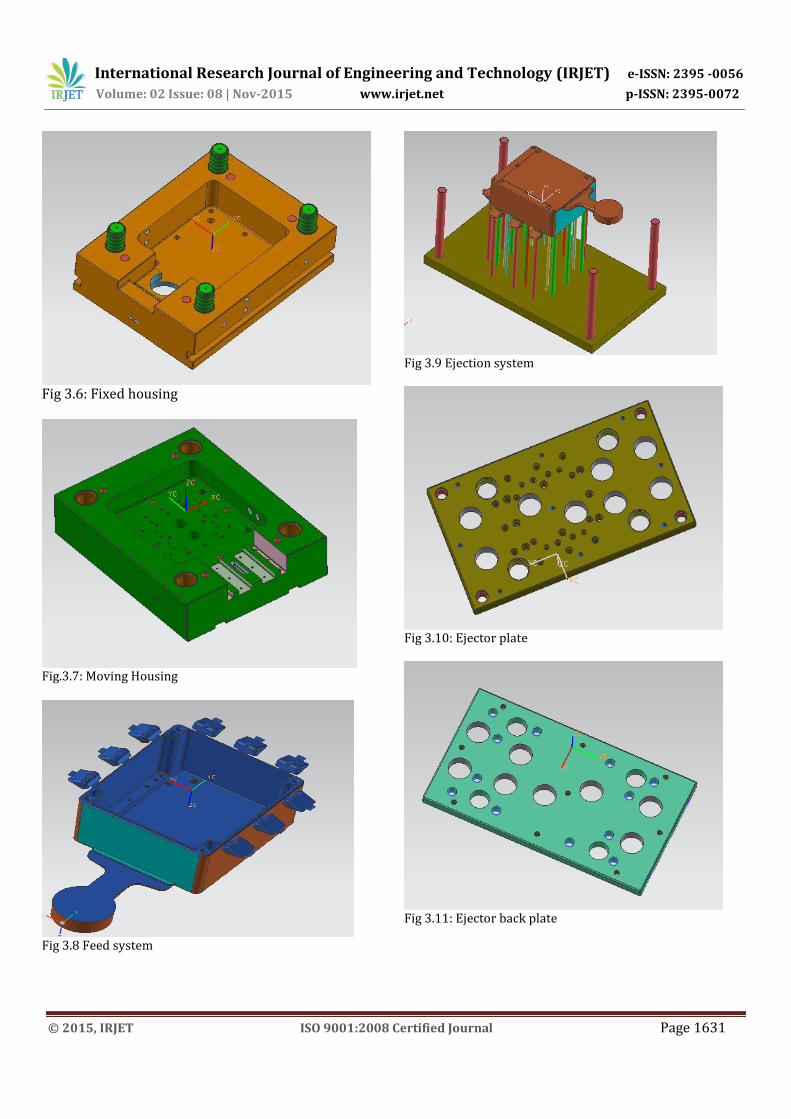
Fig 3.6: Fixed housing
Fig.3.7: Moving Housing
Fig 3.8 Feed system
Fig 3.9 Ejection system
Fig 3.10: Ejector plate
Fig 3.11: Ejector back plate

International Research Journal of Engineering and Technology (IRJET) e-ISSN: 2395 -0056
Volume: 02 Issue: 08 | Nov-2015 www.irjet.net p-ISSN: 2395-0072
© 2015, IRJET ISO 9001:2008 Certified Journal Page 1632
Fig 3.12: Bottom plate
Fig 3.13 Fixed half
Fig 3.14 Moving half
Fig 3.15 Assembly model
4. RESULTS & DISCUSSION 4.1 Cost Estimation Estimation of cost is the calculation of a probable cost of an article before manufacturing starts. It also includes predetermination of the quantity quality of material, labors etc. Estimation requires high technical knowledge about manufacturing method and operation times. In all organizations before starting the actual production or filling up the tenders, estimation is done. Over estimation leads increase the cost & hence tenders may not get. Under estimation leads to heavy loss to the concern. Hence accurate estimating is very essential. Costing of Tool It involves:
Design cost of tool Material cost Pre machining cost Precision machining cost Heat treatment cost Fitting & Assembly cost Inspection & Trial.
Designing cost: It is always preferable that standard rates per hour be used to calculate the cost of designers time and actual rate, which are usually paid on monthly or other basis.
2D designing cost- 300 per hour 3D designing cost- 500 per hour
International Research Journal of Engineering and Technology (IRJET) e-ISSN: 2395 -0056
Volume: 02 Issue: 08 | Nov-2015 www.irjet.net p-ISSN: 2395-0072
© 2015, IRJET ISO 9001:2008 Certified Journal Page 1633
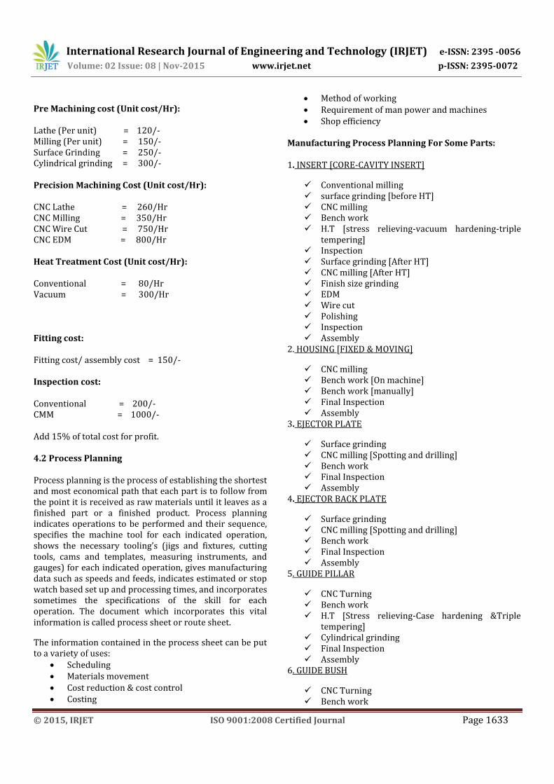
Pre Machining cost (Unit cost/Hr): Lathe (Per unit) = 120/- Milling (Per unit) = 150/- Surface Grinding = 250/- Cylindrical grinding = 300/- Precision Machining Cost (Unit cost/Hr): CNC Lathe = 260/Hr CNC Milling = 350/Hr CNC Wire Cut = 750/Hr CNC EDM = 800/Hr Heat Treatment Cost (Unit cost/Hr): Conventional = 80/Hr Vacuum = 300/Hr Fitting cost: Fitting cost/ assembly cost = 150/- Inspection cost: Conventional = 200/- CMM = 1000/- Add 15% of total cost for profit. 4.2 Process Planning Process planning is the process of establishing the shortest and most economical path that each part is to follow from the point it is received as raw materials until it leaves as a finished part or a finished product. Process planning indicates operations to be performed and their sequence, specifies the machine tool for each indicated operation, shows the necessary tooling’s (jigs and fixtures, cutting tools, cams and templates, measuring instruments, and gauges) for each indicated operation, gives manufacturing data such as speeds and feeds, indicates estimated or stop watch based set up and processing times, and incorporates sometimes the specifications of the skill for each operation. The document which incorporates this vital information is called process sheet or route sheet.
The information contained in the process sheet can be put to a variety of uses:
Scheduling Materials movement Cost reduction & cost control Costing
Method of working Requirement of man power and machines Shop efficiency
Manufacturing Process Planning For Some Parts: 1. INSERT [CORE-CAVITY INSERT]
Conventional milling surface grinding [before HT] CNC milling Bench work H.T [stress relieving-vacuum hardening-triple
tempering] Inspection Surface grinding [After HT] CNC milling [After HT] Finish size grinding EDM Wire cut Polishing Inspection Assembly
2. HOUSING [FIXED & MOVING]
CNC milling Bench work [On machine] Bench work [manually] Final Inspection Assembly
3. EJECTOR PLATE
Surface grinding CNC milling [Spotting and drilling] Bench work Final Inspection Assembly
4. EJECTOR BACK PLATE
Surface grinding CNC milling [Spotting and drilling] Bench work Final Inspection Assembly
5. GUIDE PILLAR
CNC Turning Bench work H.T [Stress relieving-Case hardening &Triple
tempering] Cylindrical grinding Final Inspection Assembly
6. GUIDE BUSH
CNC Turning Bench work

International Research Journal of Engineering and Technology (IRJET) e-ISSN: 2395 -0056
Volume: 02 Issue: 08 | Nov-2015 www.irjet.net p-ISSN: 2395-0072
© 2015, IRJET ISO 9001:2008 Certified Journal Page 1634
H.T [Stress relieving-Case hardening &Triple tempering]
Cylindrical grinding Final Inspection Assembly
7. EJECTOR GUIDE PILLAR
CNC Turning Bench work H.T [Stress relieving-Case hardening -Triple
tempering] Cylindrical grinding Final Inspection Assembly
8. EJECTOR GUIDE BUSH
CNC Turning Bench work H.T [Stress relieving-Case hardening -Triple
tempering] Cylindrical grinding Final Inspection Assembly
9. PUSH BACK PIN
CNC turning H.T [Stress relieving- hardening -Triple
tempering] Cylindrical grinding Finish size grinding Assembly
5. CONCLUSION
The proposed methodology is developed in four phases. The first phase deals with development of CAD model data in the dxf file format. The second phase deals with the extraction of the geometrical data of the component, from its corresponding data file. The third phase, feature recognition system, is used to convert the design data into manufacturing data. The final phase involves the generation of CNC part program. As the machined surfaces of a rotational part are symmetrical about their axis, they can be designed easily by revolving a line similar to the profile of the upper half of the part about the axis. Thus a 2-D profile of upper half of the part will be sufficient to represent the 3-D part completely. Hence, only the upper half of the 2-D profile of the component is used to develop the CAD model data in the dxf file format. The system is capable of accomadating more user defined features which could help in catering the growing industrial needs. A rule based system is used to sequence the processes.
The project gives a brief introduction about the work accomplished in design including the explored applications in Unigraphics & other design related
information. This project is basically dependent upon pressure die casting. It also gives a view of design consideration involved in Mould & Die casting dies. It gives the idea of flow of project from the stage of receive till dispatch of the tool. Tool design is basically a process of designing a device to get product of desired shape, form, appearance, function etc. In the process the liquid metal is injected into the cavity under external pressure and this pressure is maintained until the liquid metal cools and then the solid casting is ejected out of the cavity. In all organizations before starting the actual production or filling up the tenders, estimation is done. Over estimation leads increase the cost & hence tenders may not get.Under estimation leads to heavy loss to the concern. Hence accurate estimating is very essential. These studies are focused on estimating the cost of single cavity PDC die with respect to time, to reduce the manufacturing lead time.
REFERENCES
[1]. Shengping Shen, S. N.Atluri. “An analytical model for shot-peening Induced Residual Stresses”,CMC, vol.4,no.2,pp75-85,2006.
[2]. R. Ahmad, D.T. Gethin, R.W. Lewis, “Design Element Concept of squeeze casting process” Received 15 November 2010.Received in revised form 15 November 2011Accepted 1 December 2011.
[3]. D. Croccolo, R. Cuppini, N. Vincenzi, “Design improvement of clamped joints in front motorbike suspension based on FEM analysis” Received 14 December 2007 Received in revised form 25 November 2008 Accepted 30 November 2008.
[4]. B.H. Hu*, K.K. Tong, X.P. Niu, I. “Design and optimization of runner and gating systems for the die casting of thin-walled magnesium telecommunication parts through numerical simulation.” Pinwill Gintic Institute of Manufacturing Technology, 71 Nanyang Drive, Singapore 638075, Singapore. Received 22 May 1999.
[5]. D.H. Lee, P.K. Seo, C.G. Kang, “Die design by filling analysis of semi-solid injection forging process and their experimental investigation” Received 21 March 2001; received in revised form 24 September 2003; accepted 24 October 2003.

International Research Journal of Engineering and Technology (IRJET) e-ISSN: 2395 -0056
Volume: 02 Issue: 08 | Nov-2015 www.irjet.net p-ISSN: 2395-0072
© 2015, IRJET ISO 9001:2008 Certified Journal Page 1635
[6]. Chan WM, Yan L, Xiang W, Cheok BT (2003) A 3D CAD knowledge-based assisted injection mould design system. International Journal of Advance Manufacturing Technology 22, 387–395.
[7]. R. L. Taylor, O.C. Zienkiewicz and J.Z. Zhu (2005), The Finite Element Method: Its Basic and Fundamental, 6th ed.,Elsevier Butterworth-Heinemann.
[8]. M. Sedighi and S. Tokmechi (2008) A new approach to preform design in forging process of complex parts, Journal of Materials Processing Technology, Vol. 197, pp. 314-324.
[9]. Nafis Ahmad and A.F.M Anwarul Haque, “Manufacturing feature recognition of parts using DXF files”, 4th International conference on Mechanical Engineering, held at Dhaka, Bangladesh, December 26- 28, 2001.
[10]. Zhao, Y., Ridgway, K., Al-Ahmari, A.M.A., “Integration of CAD and a cutting tool selection system”, Computers & Industrial Engineering, Vol. 42, 2001, PP 17-34.
[11]. M. Tolouei-Rad M. and G. Payeganeh, G., “A hybrid approach to automatic generation of NC programs”, Journal of Achievements in Materials and Manufacturing Engineering, Vol. 14, No. 1-2, 2006, PP 83-89.
[12]. Yakup Yildiz, Ihsan Korkut, Ulvi Seker, “Development of a feature based CAM system for rotational parts”, Gazi University Journal of Sciences, Vol. 19, No.1, 2006, PP 35-40.
[13]. Kalta, M, Davies B.J., “IGES pre-processor to integrate CAD and CAPP for turned components”, International Journal of Advanced Manufacturing Technology, Vol. 9, No. 5, 1994, PP 291-304.
[14]. Prabhu, B.S., Biswas, S. and S.S Pande, “ Intelligent system for extraction of product data from CADD models”, International Journal of Computers in Industry, Vol. 44, 2001, PP 79-85.
[15]. Sang, C. Park., “Knowledge capturing methodology in process planning”, International Journal of Computer Aided Design, Vol. 35, 2003, PP 1109-1117.