manuals for all conveyors - bi-line...
TRANSCRIPT

MANUALS FOR ALL CONVEYORS
INSTALLATION and START-UP OPERATION
MAINTENANCE PARTS ACCESSORIES
READ THE APPROPRIATE MANUALS FOR YOUR SYSTEM BEFORE BEGINNING INSTALLATION OR OPERATION !!!
Your system may not contain all types of conveyors
TABLE OF CONTENTS
Inside Cover Electrical Grounding notice and Performance notices Warranty Page Warranty statement
Section 1 Installation and Start-Up Overview Section 2 Polycord Tray Conveyors Section 3 Power and Gravity Roller Conveyors Section 4 Rotary Tray Accumulators Section 5 Slat and Knuckle Belt Conveyors Section 6 Fabric Belt Conveyors Section 7 Conveyor Table Plumbing and Accessories Section 8 Table and Accessory Parts Quick Reference
Please note that these manuals contain operating information, service parts diagrams, maintenance procedures, and specifications covering our standard system components and certain standard options and accessories. For replacement parts in systems with non-standard or special order components, use the manual as a reference and call Bi-line service with the particular job name and location.
we convey excellence
3765 Champion Blvd Winston-Salem, NC 27115
(336) 661-1951 (800) 383-5933 Fax (336) 661-0498
2674 N. Service Road Jordan Station, Ontario, Canada L0R 1S0
(905) 562-6630 Fax (905) 562-5422
PART NUMBER B500000 Revised November 2010

LIMITED WARRANTY
READ THIS BEFORE
PROCEEDING !
GROUNDING INSTRUCTIONS!!!
This appliance must be connected to a grounded metal permanent wiring system or an equipment grounding conductor must be run with the circuit conductors and connected to the equipment grounding terminal or lead on the appliance. Please note: Bi-line will guarantee product performance only when the conveyors and accessories are properly installed and the start-up procedures are followed.
Bi-line does not guarantee the performance of components and accessories supplied by others.
Bi-line does not guarantee the performance of any Bi-line components, parts, or accessories installed by personnel not approved and authorized in advance by Bi-line Service.
Any field modifications of Bi-line equipment must be approved by Bi-line Service BEFORE the modifications are performed, and these modifications must be performed by personnel approved by Bi-line Service in advance.
3765 Champion Blvd Winston-Salem, NC 27115
(336) 661-1951 (800) 383-5933 Fax (336) 661-0498
2674 N. Service Road Jordan Station, Ontario, Canada L0R 1S0
(905) 562-6630 Fax (905) 562-5422
!

Warranty of conveyor systems: Bi-line Systems, Incorporated warrants all new equipment of its manufacture bearing the name of “Bi-line” and installed within the United States and Canada to be free from defects in material and workmanship for a period of one (1) year from the date of installation or fifteen months after the date of shipment by Bi-line, whichever occurs first. The warranty registration card must be returned to Bi-line within ten (10) days after installation. If the warranty card is not returned to Bi-line within the specified period, the warranty shall expire one year from date of shipment. If a defect in workmanship is found within the warranty period, Bi-line, at its election, will either repair or replace the defective equipment or accept the return of the equipment for full credit. In the event that Bi-line elects to repair, the labor and work to be performed in connection with the warranty will be done during regular working hours by an authorized Bi-line service technician. Defective parts become the property of Bi-line. Use of any replacement parts not authorized by Bi-line will relieve Bi-line of any further liability in connection with its warranty. In no event will the Bi-line warranty obligation exceed Bi-line’s charge for the equipment. Warranty of new accessories and replacement parts: Bi-line warrants all new parts and accessories produced or authorized by Bi-line to be free from defects in material or workmanship for a period of ninety (90) days from date of invoice. If any defect in material or workmanship is found to exist within the warranty period, Bi-line will replace the defective part without charge. The following are NOT covered by the Bi-line warranty:
• Replacement of fuses or the resetting of breakers. • Adjustment of any structural or mechanical components covered by normal maintenance procedures. • Opening or closing of any utility supply or service valves or electrical current supply devices. • Adjustment to chemical dispensing equipment. • The cleaning of valves, strainers, screens, nozzles, or spray pipes. • Performance of regular maintenance and cleaning as outlined in the operator’s manual. • Damages resulting from water conditions, accidents, unauthorized alterations, improper use, abuse, tampering,
improper installation, or failure to follow operation and maintenance procedures and intervals as outlined in the operator’s manual.
Examples of defects NOT covered by warranty include, but are not limited to:
• Damage to the exterior or interior finish as a result of any of the circumstances listed above. • Use with a utility service other than that listed on the data plate(s) or rating plate(s). • Improper connection to a utility service. • Inadequate or excessive water pressure. • Corrosion resulting from chemicals dispensed or introduced in excess of recommended concentrations. • Leaks or damage from such leaks or corrosion caused by improper installation, including those of conveyor or
machine connections. • Damage and leaks as a result of the use of chemicals not recommended for use on Bi-line equipment, or from
chemical dispensing equipment installed by others. • Failure to comply with all applicable building and equipment codes. • Damage as result of sabotage, labor disputes, or deliberate abuse.
Disclaimer of warranties and limitations of liability:
• The Bi-line warranty is limited to the extent reflected above. • Bi-line makes no other warranties, express or implied, and including but not limited to any warranty of
merchantability or fitness of purpose. • Bi-line does not authorize any other person, including persons who deal in Bi-line equipment, to change or
modify this warranty or create any other obligations in connection with Bi-line equipment. • Bi-line will not assume any extra costs for installation in any area where there are jurisdictional conflicts with any
local trades or unions. • Bi-line shall not be liable for incidental or consequential damages. • The remedies set forth above are the exclusive remedies for any defects found to exist in byline equipment and
Bi-line parts. • All other remedies are excluded, including any liability incidentals or consequential damages.
3765 Champion Blvd
Winston-Salem, NC 27115 (336) 661-1951 (800) 383-5933
Fax (336) 661-0498
2674 N. Service Road Jordan Station, Ontario, Canada L0R 1S0
(905) 562-6630 Fax (905) 562-5422

YOUR NOTES
INSTALLATION and START-UP
OVERVIEW and GENERAL GUIDELINES
INSTALLATION Page Introduction ……………………..………………………………………………………………… 1-1 Delivery and preliminary considerations ……………………..……….……………………….. 1-1 Installation overview ………………………………..……………………………………………. 1-2 Initial assembly …………………………..…………………………………………..…………… 1-2 Joining and fitting components ……………………...…………………...…………………….. 1-3 Leveling and squaring components ……………………………….…………………………... 1-5 Welding ………………………………………………………………………………..………….. 1-5 Piping and plumbing …………………………………………………………………..……….… 1-5 Electrical and Mechanical ………………………………………………………..……………… 1-7 START-UP Start-up inspection and procedures …………………………….……………………………… 1-8
3765 Champion Blvd Winston-Salem, NC 27115
(336) 661-1951 (800) 383-5933 Fax (336) 661-0498
2674 N. Service Road Jordan Station, Ontario, Canada L0R 1S0
(905) 562-6630 Fax (905) 562-5422
NOTE! READ THESE INSTRUCTIONS FIRST!
1 NOTE: Bi-line Conveyor Systems are custom manufactured for each application and there can be significant differences between installations. The configuration and layout of the equipment and the demands of the particular system will determine what components will be installed. This manual is provided for general operation, maintenance, and service information that applies to our standard builds and regular production options, and it may not reflect the specifics of any custom options. Custom options may be accompanied by supplemental technical information where necessary. For specific information not found here, contact Bi-line service with the location, the job name, and the serial number(s) applicable.
Thank you for choosing Bi-line. You have invested in a quality product that will serve your needs and enhance the operation of your facility for many years when it is installed and maintained correctly. Your machine was assembled, inspected, and thoroughly tested at the factory before being shipped to your facility. Please read and follow the instructions in the sections of this document. Failure to follow the guidelines and instructions could result in improper operation of the components, and could compromise some or all warranty considerations on the part of the manufacturer. If you have any questions after reading the instructions or you are unsure about any details, contact Bi-line Service before proceeding. Product changes Bi-line is continually engaged in improving its product lines and reserves the right to make changes in specifications, designs, and manufacturing practices without notice or incurring any obligations. Replacement parts Use only factory replacement parts for repairs or upgrades. All Bi-line parts and accessories are available through the Bi-line factory authorized service agencies. When ordering parts, please supply all applicable information such as the model number, serial number, voltage and phase where applicable, part numbers, parts descriptions, and the quantities you need.
Delivery and Preliminary Considerations INITIAL DELIVERY INSPECTIONS and PROCEDURES
• Check crating and packing for any obvious shipping damage before the shipper leaves the location. If any damage is found, initiate a damage claim with the shipper’s representative before the shipper leaves the site.
• Locate and confirm that all components included in the shipment have arrived. Note!
Some pieces of equipment may arrive from other locations and/or may be delivered by more than one shipping agent.
• After uncrating and unpacking, examine all components of the system and its
accessories for damage and, if damage is found, submit an initial or supplemental damage claim to the shipper as soon as possible.
• In all cases, inform Bi-line Service immediately of any damaged or missing components
before proceeding. NOTE! If the system is not put into service immediately, it must be stored in a warm, dry, clean location. Avoid storing in locations where the assemblies will be exposed to weather conditions, direct sunlight, large temperature changes, corrosive atmospheres, condensation or high humidity levels. Ensure that the mechanical systems will remain dry so that the bearings will not be subject to corrosion and the motor windings will not absorb moisture and potentially short to ground upon start-up.
INTRODUCTION
1-1
1

General Installation Overview What to expect and how to anticipate some aspects of the installation process. Read this guide before beginning the installation!
• It is the responsibility of the installer to follow the manufacturer’s guidelines and requirements. Failure to observe these guidelines and requirements could compromise some or all warranty considerations on the part of Champion and Bi-line. Refer to any special component installation instructions that may be included with job documents for more details regarding special issues.
• Neither Champion nor Bi-line will be responsible for the fitting of equipment supplied by
others to a Champion or Bi-line system unless proper documentation and approved drawings for the specific equipment to be joined have been supplied to Champion or Bi-line before the Champion or Bi-line components are manufactured.
DOCUMENTATION Before you begin the installation, locate and review all P&E drawings and documentation. Verify all utilities in regard to the proper sizes, ratings, and locations as per the approved drawings. If there are discrepancies or missing documentation, please contact Bi-line Service immediately for review. NOTE! Electrical schematics are stored in the electrical cabinets and should remain there for use by service and maintenance personnel. IMPORTANT! The user is responsible for conforming to all applicable building, electrical, plumbing, ventilation, and safety codes for the location. INITIAL ASSEMBLY and FITTING OF COMPONENTS The order in which you move the components into position will be determined by the physical characteristics of the facility, the fitment requirements of the components in the system, and the utility considerations. Joinery sockets are utilized on base leg assemblies and overshelf components to allow separation to meet shipping requirements and facilitate the installation process.
• Use the P&E drawings to identify and determine the location and orientation of each section of the system within the space. This is the time to determine how the components actually fit into the designated space and to plan any modifications, alterations, or additions that may be required. NOTE! Bi-line will support only those modifications to Bi-line equipment that have been previously approved and then performed by approved vendors or organizations.
• Pay special attention to how the components must fit together as this will determine the
order of installation of some components. You must then determine the best way to get the components into the final positions.
• If it is necessary to separate the tables from the base assemblies, loosen the set screws
in the joinery sockets and separate the table from the base legs. Transport the base assemblies to their locations and set in place, then move the table sections in and set in place. Make sure the legs are fully inserted into the sockets, and then tighten the set screws.
INSTALLATION
1-2
1
INITIAL ASSEMBLY and FITTING OF COMPONENTS cont. • Observe any markings that indicate adjoining surfaces, connections, or orientation.
• Use only stainless fasteners and hardware to assemble the Bi-line system. Unless
otherwise instructed, use only stainless fasteners and non-corrosive materials for adjoining or attaching the items to be supplied by others.
INITIAL SET UP
• Set all components of the system in place as per the P&E drawings and verify proper relationships and adjoining sections.
• Due to being fitted to walls, floors, and ceilings, components such as accumulator tables,
return window frame assemblies, and sight/sound barrier assemblies will likely dictate the placement and alignment of the other components in the system. See the Rotary Accumulator section of this manual for more information.
• If the system is to be connected to a dishwasher, set the dish machine in its final location
and align the tables in reference to the machine. Correct as necessary.
• If modifications to the system are required, contact Bi-line immediately for review and approval of modifications.
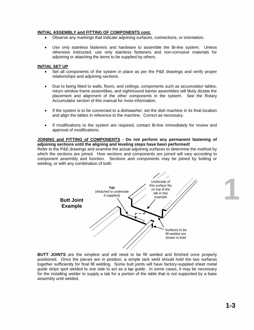
JOINING and FITTING of COMPONENTS - Do not perform any permanent fastening of adjoining sections until the aligning and leveling steps have been performed! Refer to the P&E drawings and examine the actual adjoining surfaces to determine the method by which the sections are joined. How sections and components are joined will vary according to component assembly and function. Sections and components may be joined by bolting or welding, or with any combination of both.
BUTT JOINTS are the simplest and will need to be fill welded and finished once properly positioned. Once the pieces are in position, a simple tack weld should hold the two surfaces together sufficiently for final fill welding. Some butt joints will have factory-supplied sheet metal guide strips spot welded to one side to act as a lap guide. In some cases, it may be necessary for the installing welder to supply a tab for a portion of the table that is not supported by a base assembly until welded.
Tab (Attached to underside
if supplied)
Surfaces to be fill welded are shown in bold
Butt Joint Example
Underside of this surface fits on top of the
tab in this example
1-3
1

JOINING and FITTING CONT.
OFFSET LAP JOINTS are where one or both surfaces to be joined are prepared with an offset break or a strip of sheet metal spot welded to the full length of the joint that will allow the two surfaces to overlap. These joints are to be fill welded and finished on the work surface side of the joint. In most cases, it is not necessary to weld the underside of the joint. OVERLAP or FITTED JOINTS are the joints where one piece is formed and contoured to mate with or fit over the mating portion of the adjoining component, such as where a table joins a dish machine or another table. Shown above is a table joined with another table at a curb. Consult the P&E drawings to determine whether or not the joint is bolted, welded, or simply fitted in place.
Overlap Rail Fitment
Example
This curb piece fits over the table rail in this example
Table Rail
Lap (Offset formed toward
underside)
Surfaces to be fill welded
are shown in bold
The underside of this surface
fits on top inside the lap
offset Offset Lap Joint Example
1-4
1

LEVELING AND SQUARING OF COMPONENTS – Do not perform any permanent fastening or welding of components until the aligning and leveling steps have been performed. In order to ensure proper operation and drainage, it is essential that all components must be properly fitted together, leveled, and aligned with each other, not to walls and floors and other building components.
• Height and level adjustments are made with the adjustable feet on the base assemblies. Use a level and a squaring device as necessary to ensure that all components are ready to be permanently joined and/or fastened in place. Make sure all of the adjustable feet are in good contact with the floor!
WELDING
• When performing welding on any of the components, shield any other components that could be damaged by the process.
• Use only the appropriate stainless materials and approved techniques in the welding
processes to ensure proper welding strengths, to enhance corrosion resistance, and to prevent warp and dimensional distortion of the components. Stainless TIG is the preferred method for joining Bi-line components. DO NOT use carbon welding materials when welding any of the stainless components.
• Finish the welds in such fashion as to guarantee smooth transitions between adjoining
sections and to enhance longevity and achieve acceptable appearance. Following these guidelines will reduce the possibilities of poor drainage, and will enhance operation and customer acceptance.
• Once all sections have been permanently adjoined and all peripheral devices installed,
check all access panels and covers for proper fit and operation. Resolve any fitment issues as necessary.
• Perform the required caulking and sealing, then finish and trim/remove any excess
sealant to meet all applicable codes. PIPING AND ACCESSORY PLUMBING - See the examples on the next page.
• Once all the sections and bases have been properly located and secured in place, make sure all necessary plumbing utilities are properly placed in regard to the machine components and with regard to workspace considerations. Minimum incoming water line size is ¾ inch.
• Do not install any piping or plumbing of any size smaller than what is specified by
Champion and Bi-line. If reducing is necessary, reduce the line size at the components involved. Inadequate line sizes result in friction losses that reduce the amount of flow available to the components. See the Plumbing Diagram page.
• Check the incoming water FLOWING pressure where the connection to the conveyor
components is located. When all the conveyor flow devices are operating, nominal flowing pressure should be 35 PSI in order to maintain adequate water pressure and flow rates.
• The ½ inch vacuum breaker and solenoid valve supplied with disposers are
adequate for the disposer only. Additional components in the line such as gusher heads, flushing nozzles, etc., will require a minimum of ¾ inch supply lines and comparably sized components in order to maintain the required pressures and flow rates.
1-5
1
1-6
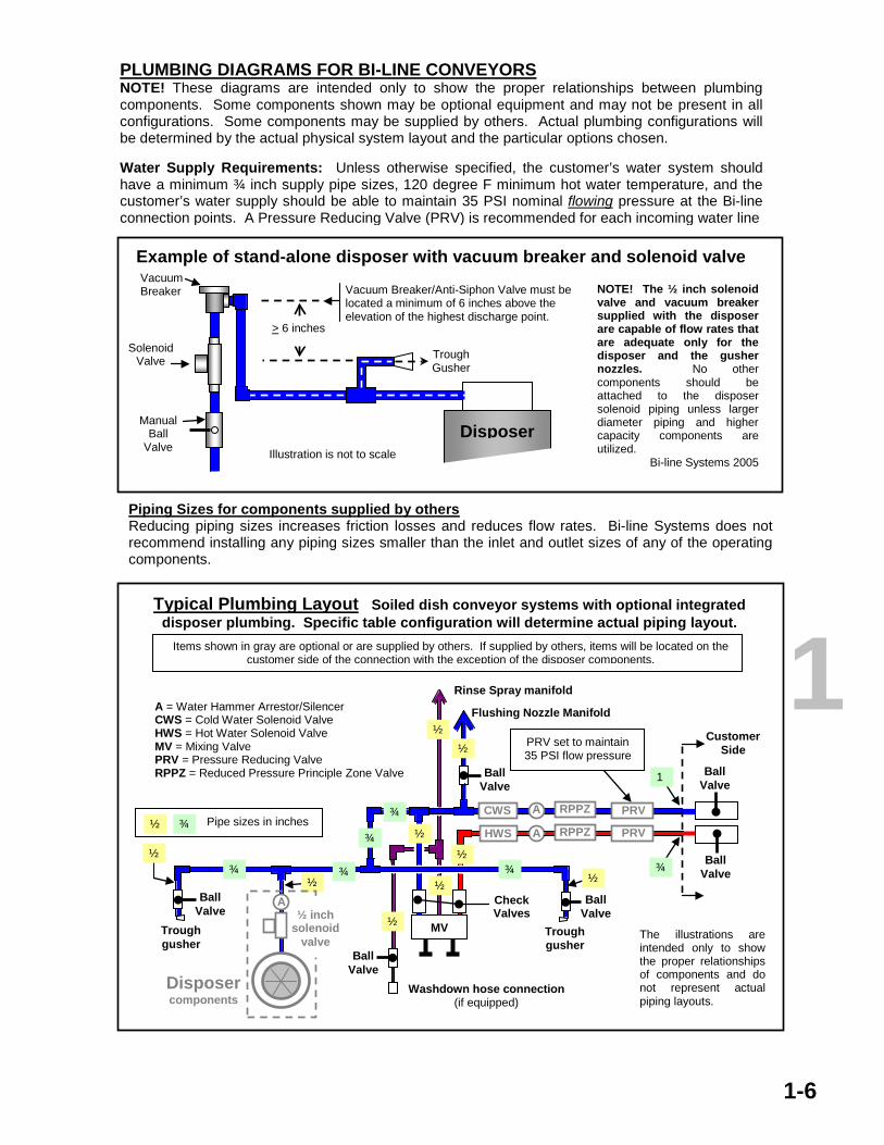
PLUMBING DIAGRAMS FOR BI-LINE CONVEYORS NOTE! These diagrams are intended only to show the proper relationships between plumbing components. Some components shown may be optional equipment and may not be present in all configurations. Some components may be supplied by others. Actual plumbing configurations will be determined by the actual physical system layout and the particular options chosen. Water Supply Requirements: Unless otherwise specified, the customer’s water system should have a minimum ¾ inch supply pipe sizes, 120 degree F minimum hot water temperature, and the customer’s water supply should be able to maintain 35 PSI nominal flowing pressure at the Bi-line connection points. A Pressure Reducing Valve (PRV) is recommended for each incoming water line
Piping Sizes for components supplied by others Reducing piping sizes increases friction losses and reduces flow rates. Bi-line Systems does not recommend installing any piping sizes smaller than the inlet and outlet sizes of any of the operating components.
Vacuum Breaker/Anti-Siphon Valve must be located a minimum of 6 inches above the elevation of the highest discharge point.
Manual Ball
Valve
Vacuum Breaker
> 6 inches
NOTE! The ½ inch solenoid valve and vacuum breaker supplied with the disposer are capable of flow rates that are adequate only for the disposer and the gusher nozzles. No other components should be attached to the disposer solenoid piping unless larger diameter piping and higher capacity components are utilized.
Bi-line Systems 2005
Disposer Illustration is not to scale
Example of stand-alone disposer with vacuum breaker and solenoid valve
Trough Gusher
Solenoid Valve
Trough gusher
MV
Rinse Spray manifold
Ball Valve
Washdown hose connection (if equipped)
Flushing Nozzle Manifold
Ball Valve
Ball Valve
Disposer components
A = Water Hammer Arrestor/Silencer CWS = Cold Water Solenoid Valve HWS = Hot Water Solenoid Valve MV = Mixing Valve PRV = Pressure Reducing Valve RPPZ = Reduced Pressure Principle Zone Valve
HWS
Trough gusher
Check Valves
A
Ball Valve
Typical Plumbing Layout Soiled dish conveyor systems with optional integrated disposer plumbing. Specific table configuration will determine actual piping layout.
The illustrations are intended only to show the proper relationships of components and do not represent actual piping layouts.
Ball Valve
Ball Valve
PRV set to maintain 35 PSI flow pressure ½
½
½
½ ½
½ ½
¾ ¾ ¾
¾
1
½
½
RPPZ
RPPZ
CWS A
¾
Pipe sizes in inches ½ ¾
A
¾ PRV
PRV
Items shown in gray are optional or are supplied by others. If supplied by others, items will be located on the customer side of the connection with the exception of the disposer components.
Customer Side
½ inch solenoid
valve
1

PIPING AND PLUMBING CONT. • If vacuum breaker/anti-siphon valves are to be installed, make sure these are located at
least six (6) inches above the maximum flow height of any components in the same flow line or the valve will not be functional and may leak. This is especially important with trough and disposer components that can become flooded and the scrapping liquid level can cover the discharges.
• Apply pipe sealing compounds or tape where applicable and take care not to cross-
thread any of the fittings.
• Ensure that considerations have been made for insulation and support bracketry where required.
• Ensure that all piping and plumbing done by others meets Champion and Bi-line
requirements.
• Ensure that the plumbing and piping installation meets all applicable codes. ELECTRICAL – All Bi-line conveyors must be properly grounded following National Electrical Code and applicable local codes!
• Make sure that all electrical utilities are adequately rated for the system loading. • Ensure that all utilities are located properly for the installation and with consideration for
the workspace. • If the installation process requires disassembly of electrical connections, check all motor
wiring connections involved for proper phase sequence to ensure proper direction of motor rotation.
• See that all wiring supplied and completed by others meets Bi-line requirements. Make
sure that any interconnection wiring for equipment supplied by others is connected properly and meets Bi-line standards.
• See that the electrical installation meets all applicable codes.
MECHANICAL – follow the instructions for each type of conveyor
• Make sure there are no obstructions to proper operation created by the installation process, or by equipment supplied by others, or by the workmanship of others.
• Once all installation has been completed, see that all screens, covers, and panels are in
place except for those that must remain out of place for start-up inspection and adjustments. Apply sealant where applicable.
• Clean all installation debris from the tables and exposed drive components. Do not
remove any protective film unnecessarily until the equipment is ready for start-up.
1-7
1

Basic Start-up Overview and Checklist Read this guide before starting the procedure! Failure to follow these guidelines could compromise warranty considerations on the part of Champion and Bi-line. For specific information about vendor assemblies in this system supplied by Champion or Bi-line, refer to the respective manufacturers’ documents included in the system manuals. WARNING! HIGH VOLTAGE DANGER! Always be aware when performing mechanical or electrical maintenance procedures. Lockout and tag out the electrical disconnects if necessary. START-UP INSPECTION and PROCEDURE This may include some peripheral and complementary equipment supplied by others that may be interconnected to the Bi-line system. Make sure these components have also been properly prepared for start-up.
• Remove any remaining protective film from the tables and troughs and panels. • Check that all caulking and sealing has been done and trimmed except for those panels
and covers that must remain off until start-up is completed.
• Check base assemblies for proper assembly, secured fasteners, and foot adjustment for good floor contact.
• Check table system for height, alignments, and check for proper drainage by applying
reasonable amounts of water to the table sections. Make sure there are no areas that retain standing water. Check for leaks between adjoining sections and resolve as necessary.
• Check and ensure that any sight/sound barriers, window frames, and any other
accessory pieces have been installed properly and that any adjoining components are joined properly to them.
• Check and ensure that all plumbing and piping connections are properly joined, are
secure and stable, and that none of the fitted connections are cross-threaded.
• Check that all wiring supplied and completed by others is proper and completed.
• Check the wiring and plumbing of any peripheral equipment where it interfaces with the conveyor system. Ensure that the interface is proper and that its operation will not adversely affect the operation of any equipment supplied by Bi-line or Champion Industries.
• Check and ensure that all utilities voltages and pressures are as specified, both on the
supply side as well as at the machine(s).
• Make sure all wire bundles are fed through the wireways and are secured.
START-UP
1-8
1
• Check all machine mounted electrical boxes for proper field wiring connections.
• Inspect the motor and drive system components before start-up for damage, loose or missing components and fasteners, obstructions, and debris, etc.
• Check drive system for alignment of components and proper tension where applicable.
• Check that the motors are clean and the ventilation is unobstructed. Oily vapor, dust, lint,
debris, etc., can accumulate and block motor ventilation which will cause overheating and premature motor failure.
• Check lubrication and oil levels of the components according to the manufacturer’s
recommendations and instructions. NOTE! Some mechanical components do not require lubrication. Consult the appropriate sections of the manuals for more information.
• Check for potential safety and mechanical hazards that may have been inadvertently
created during the installation process.
• Open the drains (if equipped with valves) and then open the water supply valves and check for leaks BEFORE switching on any of the electrical supply. Resolve any problems found as necessary to meet codes and standards of operation.
• Turn on the main electrical supply to the machine at the machine disconnect or breaker
panel and check for proper voltages and ground connections at the feed side of the control panel BEFORE turning on power at the machine. Resolve any issues found as necessary to meet codes and standards of operation.
• Turn ON the main power switch on the control panel.
• Confirm direction of motor rotation before operating the system! Improper
direction of rotation will result in damage to equipment! If any of the motors rotate in the wrong direction, check the wiring at the motor for proper phasing. If the wiring is proper on each end, check the wiring at the field interconnections.
• Start the conveyor and check all mechanical and utility operations. Make any necessary
adjustments and ensure that the belt(s) run freely in the guides/tracks and that the tension is correct.
• Observe any stop, limit, fault, or accumulation switches for proper operation and adjust
as necessary.
• Review the flow and drainage systems as the system operates and make adjustments as necessary. This includes the troughs and spray systems of any scrapping tables included.
• Observe the operation of any spray systems and gusher nozzles and the related drains.
Take corrective actions or make adjustments as necessary. This includes any belt cleaning systems and the related drains.
• Apply the expected loading to the conveyor and check for proper operation and tracking.
Adjust as necessary. Make sure all components run without vibration, shuddering, etc.
1-9
1

• Check the operation of the peripheral equipment connections such as valves, piping, electrical, etc., and any disposals, pulpers, tray carts, lift systems, etc, that mechanically or electrically interface with the conveyor system.
• Observe the interaction of a dish machine and any peripheral equipment with the
conveyor system. Make adjustments as necessary and document any discrepancies for later review.
• When inspection and start-up are completed and no issues regarding the conveyor or
accumulator systems remain, put all remaining screens, access panels, and covers, etc. in place and seal where applicable.
Any issues that cannot be immediately resolved by the technicians and representatives on-site must be documented and reported to Bi-line Service as soon as possible. See the individual conveyor manuals for more specific checks before start-up.
1-10
1

NOTES Revisions: Update plumbing diagram and add as separate page
3765 Champion Blvd Winston-Salem, NC 27115
(336) 661-1951 (800) 383-5933 Fax (336) 661-0498
2674 N. Service Road Jordan Station, Ontario, Canada L0R 1S0
(905) 562-6630 Fax (905) 562-5422
1

Bi-line is continually reviewing its products and manufacturing procedures for ways to improve performance and reliability and to reduce costs to the end user. The information within these manuals is subject to correction and updating as the review process occurs. If you have any questions or concerns please feel free to contact Bi-line Service at any of the phone numbers listed on this page. Thank you for choosing Bi-line.
Section 2 Polycord Tray Conveyors Section 3 Power and Gravity Roller Conveyors Section 4 Rotary Tray Accumulators Section 5 Slat and Knuckle Belt Conveyors
Section 6 Fabric Belt Conveyors Section 7 Conveyor Table Plumbing and Accessories Section 8 Table and Accessory Parts Quick
Reference
NOTE! Strong solutions used during the warewashing or cleaning processes should be regularly checked for pH levels. pH values below 4.5 or above 9.0 will damage the stainless steel and plastic parts of the machines. Solutions containing chlorine, ammonia, or phosphoric acid are not recommended as these solutions will attack the plastic components, and if not thoroughly flushed away, may damage the stainless steel surfaces also. Always thoroughly clean and flush the conveyor system before leaving the system idle for any length of time.
3765 Champion Blvd Winston-Salem, NC 27115
(336) 661-1951 (800) 383-5933 Fax (336) 661-0498
2674 N. Service Road Jordan Station, Ontario, Canada L0R 1S0
(905) 562-6630 Fax (905) 562-5422

POLYCORD CONVEYORS OPERATION AND MAINTENANCE MANUAL
OPERATION Page Operation ……………………………………………………………………………………..… 2-1 Operator control panel ………………………………………………………………………… 2-2 CLEANING Cleaning and precautions …………………………………………………………………….. 2-3 MAINTENANCE Belt adjustments………………………………………………………………………………… 2-4 Inline drive belt routing ………………………………………………………………………... 2-4 End drive belt routing ………………………………………………………………………...… 2-5 Re-direct belt routing ………………………………………………………………………..…. 2-5 Idler/tail belt routing ………………………………………………………………………...….. 2-6 Drive belt routing for Canadian built conveyors …………………………………………….. 2-6 Table turn and corner components …………………………………………………………… 2-7 New polycord belt installation and belt repairs …………….…….………………………….. 2-7 Polycord welding procedures ………………………………………………………………….. 2-8 Control panel and electrical cabinet ………………………………………………………….. 2-9 Gearmotor maintenance ……………………………………………………………………….. 2-10 Note: Electrical schematics are stored in the electrical cabinet and shoud be left there for use by service personnel.
3765 Champion Blvd Winston-Salem, NC 27115
(336) 661-1951 (800) 383-5933 Fax (336) 661-0498
2674 N. Service Road Jordan Station, Ontario, Canada L0R 1S0
(905) 562-6630 Fax (905) 562-5422
2

POLYCORD TRAY CONVEYOR SYSTEMS Use the P&E drawings to identify all the components in the system, their orientations to each other, and verify how all the components fit together. Check the dimensions of the space and compare it to the P&E drawings. If there are discrepancies, notify Bi-line immediately before going further. FOLLOW THE INSTALLATION OVERVIEW SECTION FOR DETAILS ON TABLE INSTALLATION.
OPERATION There may be controls for other conveyors located on this panel. Shown below are the basic control configurations. Consult the instructions for any other conveyors that may be controlled from this panel. IMPORTANT! When placing trays on a conveyor with turns, always leave sufficient spacing between trays so that the trays can negotiate the turns without binding against each other or jamming.
2-1
Polycord Tray Conveyors
PO Box 16009 Winston-Salem, NC 27115 (336) 661-1951 Fax (336) 661-0498
NOTE! READ THESE INSTRUCTIONS BEFORE INSTALLING OR OPERATING THE CONVEYOR SYSTEM!
Multiple conveyors with optional controls for both
Multiple conveyors with optional controls for primary
Conveyor Manual Advance Station Typical Conveyor Control Panel Layouts
Remote START-STOP
Station
Continued on next page
2

OPERATION, cont. Read this page carefully before beginning operation!
2-2
Manual Conveyor Advance Station. These stations are applied to conveyors that do not run continuously once started, and are usually positioned at workstations along the conveyor route. The conveyors controlled by these stations will advance only as long as the black pushbutton is pressed. To operate, press the green START pushbutton for that conveyor on the main panel or a remote START-STOP Station to enable the conveyor, then press the black conveyor advance pushbutton to advance the conveyor. The belt wash and rinse systems on these conveyors operate only while the advance pushbutton is being pressed.
Optional START-STOP stations may be located at any point along the conveyor route. The switches operate in the same manner as the START-STOP switches on the main control panel. Each START-STOP Station operates only one (1) conveyor.
STOP
START
START
MAIN DISCONNECT
SPEED*
STOP
Green Push
Button
Red Push
Button
OPTIONAL Speed Control allows the operator to vary the speed of the conveyor to meet system demand.
RED Pilot Lamp Indicates the conveyor is activated
Pressing this pushbutton
will STOP the conveyor
Pilot lamps indicate the activation of specific conveyor features such as accumulation, belt washing systems, etc., or a fault in operation such as improper loading or a jam, etc.
OFF
480 VAC Disconnect
2
480VAC disconnect replaces 125VAC disconnect where
applicable.
This pushbutton STARTS the conveyor. Always make sure the conveyor is clear to operate before starting!!! Secure all scrap pans and screens in place and close all access doors before starting the conveyor. Failure to do so could cause injury or damage or both. For Manual Advance conveyors, the START switch on the main panel or on the Remote station must be pressed before the black pushbutton on the Manual Advance Station will advance the conveyor. See Manual Advance Station below.

CLEANING DO NOT SPRAY WATER DIRECTLY INTO ANY ACTUATOR SWITCHES, OPTICAL DETECTION DEVICES, OR ELECTRICAL PANELS OR BOXES. Strong solutions used during the warewashing or cleaning processes should be regularly checked for pH levels. Any pH value below 4.5 or above 9.0 will damage the stainless steel and plastic parts of the machines. If it is necessary to use a strong solution to clean the surfaces, all residue should be thoroughly flushed away from all surfaces and components immediately, and the table surfaces should be wiped down with a soft cloth to prevent corrosive damage to the components and to avoid water spotting. Keeping the conveyor system clean is essential to proper operation and sanitation guidelines. For general cleaning,
• Clean stainless steel surfaces with a soft cloth and a mild detergent intended for use with stainless steel.
• Flush with clean water or wipe down with a clean wet cloth, and then wipe dry to avoid
streaking and spotting. • Chlorinated detergents and sanitizing agents will damage stainless steel unless
thoroughly flushed or wiped away. During the work periods, keep the conveyor relatively clean of accumulated debris.
At the end of each meal period or for shutdown, stop the system and turn the power switch off.
• Clean away any accumulated food debris from the table surface.
• Start the conveyor and clean the belting with a clean wet towel by gently gripping the belting in the middle of the table with the towel and allow the belt to run through the towel until the belt is clean.
• If the conveyor is equipped with optical detection devices, DO NOT USE ABRASIVES
OR DIRTY WIPING CLOTHS ON THE LENSES.
• Wipe the table surfaces down with a soft clean cloth to prevent spotting.
• Empty and clean the Sediment Tray, if equipped.
2-3
2
!

BELT ADJUSTMENTS Depending on the particular drive units, belt adjustments are made either by adjusting the height of the Drive Gearmotor in the guides with the jack screw, or at the Idler/Tail locations with the snubber sheaves, but not both.
BELT TENSION Proper tension is achieved when the belt can be lifted with little effort approximately 1.5 inches (38 mm) from the top of the guide blocks in the middle of the length of the table, or approximately 2 inches (50 mm) from the table surface before becoming noticeably tighter. Too much tension will damage or break the belt due to stress on the vulcanized joints in the belt and will cause premature wear of the drive components. Insufficient tension will cause the belt to run erratically and will result in the belt becoming separated from the guides and sheaves.
2-4
GUIDE BLOCK
Approximately 2 inches
Approximately 1.5 inches POLYCORD TENSION
Approximate center of table length Table surface
Inline Drive Routing
LOWER NUT
MOTOR Part Number B500074
SIDE VIEW (Not to scale)
GEAR REDUCER Motor Plate
Decrease
Increase
UPPER NUT
THREADED ROD
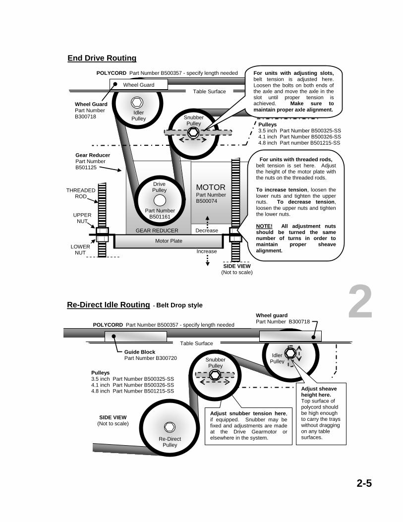
For units with threaded rods, belt tension is set here. Adjust the height of the motor plate with the nuts on the threaded rods. To increase tension, loosen the lower nuts and tighten the upper nuts. To decrease tension, loosen the upper nuts and tighten the lower nuts. NOTE! All adjustment nuts should be turned the same number of turns in order to maintain proper sheave alignment.
Table Surface
Pulleys 3.5 inch Part Number B500325-SS 4.1 inch Part Number B500326-SS 4.8 inch Part Number B501215-SS
Guide Block Part Number B300720
POLYCORD Part Number B500357 - specify length needed
Gear Reducer Part Number B501125
2 Drive Pulley
Part Number B501161
Snubber Pulley
Idler Pulley
For units with adjusting slots, belt tension is adjusted here. Loosen the bolts on both ends of the axle and move the axle in the slot until proper tension is achieved. Make sure to maintain proper axle alignment.
POLYCORD Part number B500357 - specify length needed -
2-5
Re-Direct Idle Routing - Belt Drop style
SIDE VIEW (Not to scale)
Re-Direct Pulley
Idler Pulley
Adjust snubber tension here, if equipped. Snubber may be fixed and adjustments are made at the Drive Gearmotor or elsewhere in the system.
Snubber Pulley
Guide Block Part Number B300720
Wheel guard Part Number B300718
Pulleys 3.5 inch Part Number B500325-SS 4.1 inch Part Number B500326-SS 4.8 inch Part Number B501215-SS
Adjust sheave height here. Top surface of polycord should be high enough to carry the trays without dragging on any table surfaces.
POLYCORD Part Number B500357 - specify length needed
Table Surface
End Drive Routing
LOWER NUT
MOTOR Part Number B500074
SIDE VIEW (Not to scale)
GEAR REDUCER Motor Plate
Decrease
Increase
UPPER NUT
THREADED ROD
For units with threaded rods, belt tension is set here. Adjust the height of the motor plate with the nuts on the threaded rods. To increase tension, loosen the lower nuts and tighten the upper nuts. To decrease tension, loosen the upper nuts and tighten the lower nuts. NOTE! All adjustment nuts should be turned the same number of turns in order to maintain proper sheave alignment.
Wheel Guard
Gear Reducer Part Number B501125
Pulleys 3.5 inch Part Number B500325-SS 4.1 inch Part Number B500326-SS 4.8 inch Part number B501215-SS
Idler Pulley
Wheel Guard Part Number B300718
POLYCORD Part Number B500357 - specify length needed
Table Surface
Snubber Pulley
For units with adjusting slots, belt tension is adjusted here. Loosen the bolts on both ends of the axle and move the axle in the slot until proper tension is achieved. Make sure to maintain proper axle alignment.
2
Drive Pulley
Part Number B501161

2-6
Idler/Tail Routing - Return Belt Lift Style
SIDE VIEW (Not to scale)
Idler Pulley
Guide Block Wheel Guard Table Surface
Adjust sheave height here.
Adjust snubber tension here, if equipped. Snubber may be fixed and tension adjustments are made at the Gearmotor or elsewhere in the system.
Guide Block Part Number B300720
Wheel Guard Part Number B300718
Pulleys 3.5 inch Part Number B500325-SS 4.1 inch Part Number B500326-SS 4.8 inch Part Number B501215-SS
Snubber Pulley
POLYCORD Part number B500357 - specify length needed
Guide Block
Guide Block Guide Block Table Surface
Motor
Gearmotor Assembly Part Number BC04507
From outside sheave
To inside sheave
To outside sheave
Gear Reducer
From inside sheave
OUT IN
Turnbuckle Adjust initial polycord
tension here.
Drive Routing for Bi-line Polycord Systems Manufactured in Canada
Double Sheave
Drive Pulley
SIDE VIEW Illustration is not to
scale
POLYCORD Part Number B500357 – specify length needed
Part Number BC04506
Idler Pulley Idler Pulley
Idler Pulley 3 inch
5 inch 5 inch
Idler Pulleys 3 inch Part Number BC04508 5 inch Part Number BC04509
Guide Block Part Number B300720
2

Polycord Corner Section Parts NEW POLYCORD BELTING If there are turns in the conveyor system, this process will likely require two personnel, one to feed and one to thread the polycord without kinking and twisting.
1. Do not feed the polycord directly from the carton. Uncoil the polycord and make sure it will lie out straight before attempting to thread it through the conveyor.
2. There must be absolutely no kinks or twists in the polycord when threading
the cord onto the conveyor or the cord will not track properly. Poor tracking will cause the belt to come off the pulleys and out of the guides and can result in damage to the polycord.
3. In order to properly weld the two ends together, install the polycord in such
a manner as to have clear access on the table surface to the two ends. The center of a straight run section of a table is recommended, since that is where the tension measurement is made.
4. The welds must be done properly in order for the polycord to perform
properly and remain durable. See instructions on the next page.
2-7
2 Top View Illustration is not to scale
Removable Corner Guide Manufactured per specific conveyor layout. Contact Bi-line Service for replacement.
Return Side Components
Pulley Part Number B500325-SS Requires fasteners: (1) ½ -13 x 2 Hex Bolt SS Part Number 107586 (1) ½ -13 Hex Nut SS Part Number 104584 (1) ½ inch Lock Washer SS Part Number 107589
Set Screws. Don’t forget to tighten them.
Corner Guide Bracket Part Number B700090 Polycord and guard portion of the bracket are oriented toward the outside of the turns.
Table Top Components CORNER WHEELS Part Number B701037 3 components, less fasteners B701037 Individual Components Pulley, table top side Part Number B500230 Flange (axle) Part Number B500231 Bearing (not shown) Part Number B500293 Requires fasteners: (1) 5/16-18 x ¾ hex head bolt SS Part Number 100739 (1) 5/16 lockwasher SS Part Number 106013

PO Box 16009 Winston-Salem, NC 27115 (336) 661-1951 Fax (336) 661-0498
2-8
POLYCORD WELDING
2) CUTTING Both ends must be cut square and cleaned thoroughly for several inches from the cut.
The objective when welding is to fuse the nylon center cord ends together and to fuse the poly cord body without contaminating either. The melting and carbonization points of the two materials are different, so it is necessary to melt the polycord body over a greater distance in order to properly fuse the nylon. If the joint is done properly, the excess melted polycord body can be neatly trimmed away leaving a joint that is hardly visible. 1) MEASURING FOR THE CUT Make sure the polycord is properly routed through all the sheaves and that any adjustable pulleys are positioned at the approximate center of adjustment. Pull together and overlap the ends and have someone check for tension while the Polycord is held tightly in position. Place a mark approximately in the center of the distance the ends are overlapped with each other. That mark on the overlapped pieces is where the cuts will be made.
POLYCORD CROSS SECTION
Polycord Part Number B500357 - Specify length needed -
Nylon Center Cord
3) DRILLING Use a 1/8 inch drill bit and drill the nylon center cord out to a depth of 3/8 to ½ inch. Make sure the drill is straight and does not slip to the side and cut into the polycord body or you will have to cut and start over. Clean all nylon fragments from the drilled area. Nylon fragments will plasticize and blacken during welding which will contaminate and weaken the weld.
3/8 to ½ inch
3/8 to ½ inch
Nylon Cord Nylon Cord
Drill and clean out the debris
4) WELDING Follow the instructions for the particular welding kit you have. If you have no experience, it is a good idea to use two short pieces of polycord to practice a weld or two before performing a weld on the conveyor polycord. NOTE! Always allow the welds to cool 5 minutes before trimming or applying tension to the belt. The weld should look similar to the illustrations below when the welding process is correct. The melted excess polycord body should be symmetrical all the way around.
5) TRIMMING and FINISHING Trim the melted excess off the joint flush with the unmelted surfaces. If the weld is correct, there will be no black carbonized nylon particles visible and the weld should be hardly visible.
Melted excess
Melted excess trimmed away
2
Polycord Body

2-9
2 CONTROL CABINET INTERIOR COMPONENTS – General Configuration Shown is a general layout of components and their approximate locations. The number and types of components and the presence of timers will vary with conveyor types, system configurations, and optional equipment. Not all components shown will be present in all configurations.
Control Transformer 230V P/N B500104 460V P/N B502471
Terminal Blocks
Fuse Blocks 250V Part Number B500793 600V Part Number B500792
Fuses for 24 Volt 1 amp P/N B500801 2 amp P/N B500802 Fuses for 600 Volt 1 amp P/N 112901 10 amp P/N 100913
Relay Sockets, each Part Number B500598
Relays, each 24VAC 4Pole
Part Number B500604
AC Variable Speed Drive 1
Motortronics
230V P/N B501018 460V P/N B502467
Mitsubishi 230V P/N B502437
AC Variable Speed Drive 2
If equipped, see Drive 1 for part
numbers.
Repeat Cycle Timer Part Number B500608 Timer Socket (not shown) Part Number B500599
Base electrical cabinet BOM numbers are B701354 for 18 inch, and B701355 for 24 inch.
START
STOP
Green Push
Button
Red Push
Button
Conveyor Manual Advance Station Palm Switch Assembly Part Number B501611 Enclosure Part Number B502283
230V CIRCUIT BREAKER/DISCONNECT Part Number B500138 230V COVER BOOT Part Number B500338
480V DISCONNECT OPERATOR (on door) Part Number B500621 480V DISCONNECT, 4 pole (inside cabinet) Part Number B500622
PILOT LAMPS, each Part number B502176
GREEN PUSH BUTTON Part Number B502109 CONTACT BLOCK N.O. Part Number B502107
RED PUSH BUTTON Part Number B502110 CONTACT BLOCK N.C. Part Number B502108
CONTACT BLOCK MOUNTING ADAPTER, 1 required per pushbutton Part Number B502106 Pushbutton parts also used in Remote START-STOP Stations. Remote START-STOP enclosure P/N B502284
SPEED CONTROL Single Conveyor ……………………….. Part Number B501158 Two Conveyor, single control Knob …. Part Number B501224 Knob only ……………………………….. Part Number B501158-1
OR
CONTROL PANEL COMPONENTS NOTE! The actual layout and quantity of control components will vary with the configuration of the conveyor system, the number of conveyor drives, and the options installed.

CHECK THE MOTOR AND GEARBOX EVERY 6 MONTHS for leakage and oil level. Make sure the motor ventilation is not blocked with debris, lint, residue, etc. If adding oil, do not mix oil types. If changing the oil, flush the gearbox with petroleum oil until all traces of contaminants are removed. Replace the drain plug and fill to the proper level with the recommended oil and replace the fill plug. Do not overfill. It is recommended that the gearbox oil be changed after the first 250 hours of operation, and thereafter every 10,000 hours for mineral oils, and every 20,000 hours for synthetics. Do not overfill. TYPICAL LUBRICANTS for all gearboxes Oils VG220, CLP 220, PGLP 220, and PGLP 460 complying with DIN 51502 and 51517 are suitable. DO NOT MIX OIL TYPES! Suggested oils for all gearboxes Mineral oils: Shell Omala EP220 or equivalent Synthetic oils: Shell Omala HD220 or equivalent NOTE! DO NOT MIX OIL TYPES in service or as waste! Synthetic oils with a polyglycol base (PGLP, etc.) must be kept separate from mineral oils and are to be disposed of as special waste.
Polycord Gearmotors and Power Roller Below-Table Gearmotors
MOTOR
GEARBOX
Output Shaft Bearing Plate
Vent Plug Fill Plug
Either side bearing plate
Drain Plug
Drain Plug
Not to scale
Recommended oil level
Motor and Gearbox painted white
GEARMOTOR MAINTENANCE
2-10
2

NOTES
3765 Champion Blvd
Winston-Salem, NC 27115 (336) 661-1951 (800) 383-5933
Fax (336) 661-0498
2674 N. Service Road Jordan Station, Ontario, Canada L0R 1S0
(905) 562-6630 Fax (905) 562-5422
2

ROLLER CONVEYORS
POWER ROLLER GRAVITY ROLLER
OPERATION AND MAINTENANCE MANUAL
For all units delivered after July 1, 2006 OPERATION Page Control panel and operating instructions ………………………………………………….…. 3-1 CLEANING Instructions and precautions ………………………………………………………………….. 3-3 MAINTENANCE General Power Roller Layout ……………………………………………….………………... 3-4 Power Roller Drive system ……………………………………………………………………. 3-4 Gravity Roller System ………………………………………………………………………….. 3-5 Control panel and electrical cabinet components …………………………………………… 3-6 Gearmotor maintenance ……………………………………………………………………..... 3-7 Note: Electrical schematics are stored in the control cabinet and should be left there for use by service personnel.
3765 Champion Blvd Winston-Salem, NC 27115
(336) 661-1951 (800) 383-5933 Fax (336) 661-0498
2674 N. Service Road Jordan Station, Ontario, Canada L0R 1S0
(905) 562-6630 Fax (905) 562-5422
3

PO Box 16009 Winston-Salem, NC 27115 (336) 661-1951 Fax (336) 661-0498
POWER ROLLER CONVEYORS
READ ALL INSTRUCTIONS BEFORE YOU BEGIN INSTALLATION OR OPERATION!
These instructions are intended to guide the installer and provide a method of anticipating some of the aspects of custom conveyor installations. Table assembly and installation instructions are included in the Installation and Start-up Overview section at the beginning of this manual. It is important for the installer and all supervisory personnel involved in the installation to read the Installation Overview section BEFORE beginning any portion of this process. Failure to follow the installation, operation, and maintenance procedures may affect warranty considerations on the part of Bi-line.
OPERATION Power roller conveyors are designed to carry standard 20” by 20” dish racks to a gravity roller conveyor or a dish machine. The conveyor operates as a low-pressure accumulation system by utilizing a “clutch” type mounting of the rollers that allows the roller to stop turning while the chain continues to run. This arrangement eliminates the need for stopping and restarting the conveyor to accommodate rack handling back-ups or momentary stops. NOTE! When loading racks onto a conveyor with turns, always leave 6 to 8 inches between racks in order to maintain sufficient spacing for the racks to negotiate the turns in the conveyor path. The conveyor speed is controlled by a variable speed AC motor drive controller, and conveyor speed is preset to run at optimum for the specified ware handling system. If necessary, conveyor speed can be adjusted at the motor controller by qualified service personnel. An optional control mounted on the main control panel allows speed adjustments by turning the speed control knob clockwise to increase the speed and counterclockwise to reduce the speed. Conveyor Start/Stop controls are provided as standard equipment on the main control panel, and remote Start/Stop stations are provided as an option and may be mounted at any location along the conveyor routing. All controls are interwired per UL, USNEC, and CSA, and meet all safety requirements. Before starting, open drain valves and water valves as necessary, and make sure all screens and scrapping equipment and devices are in position.
NOTE!
3-1
3

OPERATION, cont There may be controls for other conveyors located on this panel. Shown below are the basic control configurations. Consult the instructions for any other conveyors that may be controlled from this panel.
3-2
Multiple conveyors with optional controls for both
Multiple conveyors with optional controls for primary
Conveyor Manual Advance Station Typical Conveyor Control Panel Layouts
Remote START-STOP
Station
START
STOP
MAIN DISCONNECT
SPEED
GREEN
RED This pushbutton STOPS the conveyor.
RED pilot lamp indicates when the conveyor is activated.
CIRCUIT BREAKER Turns ON main power to all the components in the control cabinet.
RED pilot lamps indicate activated conveyor functions and alarms
SPEED CONTROL (optional) allows the operator to vary the conveyor speed to accommodate system demand.
Optional START-STOP stations may be located at any point along the conveyor route. The switches operate in the same manner as the START-STOP switches on the main control panel. Each START-STOP Station operates only one (1) conveyor.
STOP
START
3
This pushbutton STARTS the conveyor. Always make sure the conveyor is clear to operate before starting!!! Secure all scrap pans and screens in place and close all access doors before starting the conveyor. Failure to do so could cause injury or damage or both. For Manual Advance conveyors, the START switch on the main panel or on the Remote station must be pressed before the black pushbutton on the Manual Advance Station will advance the conveyor. See Manual Advance Station below.

CLEANING DO NOT SPRAY WATER DIRECTLY INTO ANY ACTUATOR SWITCHES, OPTICAL DETECTION DEVICES, OR ELECTRICAL PANELS OR BOXES. NOTE! Solutions used during the warewashing or cleaning processes should be regularly checked for pH levels. Any pH value below 4.5 or above 9.0 will damage the stainless steel and plastic parts of the machines. Solutions containing chlorine, ammonia, or phosphoric acid are not recommended. If it is necessary to use a strong solution to clean the surfaces, the residue should be thoroughly flushed away from all surfaces and components immediately, and the surfaces should be wiped down with a soft cloth to prevent corrosive damage to the components and to avoid water spotting. Keeping the conveyor system clean is essential to proper operation and sanitation guidelines.
• For general cleaning, clean stainless steel surfaces with a soft cloth and a mild detergent. Flush with clean water and wipe dry. Chlorinated detergents and sanitizing agents will damage stainless steel unless thoroughly flushed away.
• During the work periods, use the wash down hose and the scrapping station spray
hoses to keep the conveyor relatively clean of accumulated debris. Empty and rinse the scrap pan(s) in the drain end of the table.
• At the end of each meal period, stop the system, empty and clean the scrap tray(s),
and gently wash down the conveyor and table surfaces with the wash down hose and/or spray nozzles.
• For shut down or at the end of the work shift,
o Thoroughly wash down the conveyor system, the tables, and trough system and
drains, including the conveyor return tracks and return trough under the table. Do not spray water directly into any actuator switches or optical detection devices mounted on the equipment, or into electrical panels or boxes.
o Thoroughly wash the food debris from the rollers and trough skate wheels,
especially in the roller and skate wheel bearing areas. Debris must be kept out of these bearing areas in order for the rollers and wheels to turn easily.
o Use a soft cloth to wipe off any debris or film buildup from the lens surfaces of
any optical detection devices mounted on the table system. Do not use abrasives or dirty cleaning cloths on the lenses.
o Remove and clean the scrap screens thoroughly and replace. Make sure the
screens are properly seated.
o Wipe down the table surfaces with a soft clean cloth to prevent spotting.
3-3
3
!

MAINTENANCE POWER ROLLER CONVEYORS
3-4
TOP VIEW
Roller Assembly, see below Gearmotor inline mounted (Shown with cover off)
General Power Roller Layout Parts listed are for US versions unless otherwise noted
Drive System Cover
Sediment Drawer (if equipped) Part Number B702822-1
Cover
Gearmotor underslung mounted
SIDE VIEW NOTE: Systems manufactured in our Canadian facilities may have some custom application components. For parts not listed here, please call Bi-line Service with the job name and parts details.
Chain, specify length Master Link (not shown) 1 per chain Part Number B501252 Part Number B500285 straight Half Link (not shown) 1 per chain Part Number B503059 Part Number B500285-SB curved
Idle Sprocket Part Number B501179 Sprocket Bearing (not shown) 2 required per sprocket Part Number B502134
UHMW Chain Guide - specify length required Straight sections Part Number B501841 Curved sections Part Number B501842
SIDE
VIEW
Straight Section Roller Tapered Roller for curved sections Roller Shafts 22 inch B701175-1 22 inch B701194-1 24.625 inch B501177-1 For Canadian manufactured units, roller complete w/shaft: Straight Section Roller, 24.125 inch Part Number BC04503 Tapered Curve Section Roller multi-piece 27.5 inch Part Number BC04504
Roller Bearing, 2 per straight roller, 4 per curved split roller Part Number B500295-1 Shaft Bearing, 2 per shaft Part Number B700293-F
Roller Assemblies
Roller Sprocket, 1 per roller Part Number B501931-SS (US) Part Number BC04502 (Can.)
FRONT VIEW 3
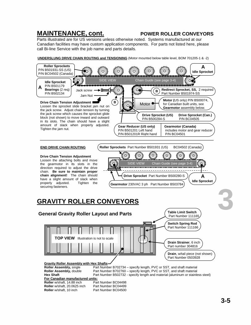
MAINTENANCE, cont. POWER ROLLER CONVEYORS Parts illustrated are for US versions unless otherwise noted. Systems manufactured at our Canadian facilities may have custom application components. For parts not listed here, please call Bi-line Service with the job name and parts details.
GRAVITY ROLLER CONVEYORS
3-5
3 TOP VIEW Illustration is not to scale
Table Limit Switch Part Number 111165 Switch Spring Rod Part Number 111166 Drain Strainer, 6 inch Part number 304816 Drain, w/tail piece (not shown) Part Number 0503928
Gravity Roller Assembly with Hex Shafts Roller Assembly, single Part Number B702734 – specify length, PVC or SST, and shaft material Roller Assembly, double Part Number B702760 – specify length, PVC or SST, and shaft material Hex Shaft Part Number B502732 - specify length and material (aluminum or stainless steel) For Canadian manufactured units: Roller w/shaft, 14.88 inch Part Number BC04498 Roller w/shaft, 20.0625 inch Part Number BC04499 Roller w/shaft, 10 inch Part Number BC04500
General Gravity Roller Layout and Parts
END DRIVE CHAIN ROUTING
Drive Chain Tension Adjustment Loosen the attaching bolts and move the gearmotor in its slots in the direction required to adjust the drive chain. Be sure to maintain proper chain alignment! The chain should have a slight amount of slack when properly adjusted. Tighten the securing fasteners.
Drive Chain Tension Adjustment Loosen the sprocket slide bracket jam nut on the jack screw. Adjust chain tension by turning the jack screw which causes the sprocket glide block (not shown) to move inward and outward in its slots. The chain should have a slight amount of slack when properly adjusted. Tighten the jam nut.
Roller Sprockets P/N B501931-SS (US) P/N BC04502 (Canada)
Redirect Sprocket, SS, 2 required Part Number B501974-SS
UNDERSLUNG DRIVE CHAIN ROUTING and TENSIONING (Motor mounted below table level, BOM 701205-1 & -2)
Motor (US only) P/N B500074, for Canadian built units, see Gearmotor assembly below.
SIDE VIEW Chain Guide (see page 3-4)
Motor
Jam Nut
Jack screw
Drive Sprocket (US) Drive Sprocket (Can.) P/N B500284-S P/N BC04505
B
B
Gear Reducer (US only) Gearmotor (Canada) P/N B501201 Left hand includes motor and gear reducer P/N B501201R Right hand P/N BC04501
Idle Sprocket P/N B501179 Bearings (2 req) P/N B502134
Gearmotor 230VAC 3 ph Part Number B503784
Drive Sprocket Part Number B500280-S
Roller Sprockets Part Number B501931 (US) BC04502 (Canada)
SIDE VIEW Chain Guide (see page 3-4)
A Idle Sprocket
A
A Idle Sprocket

3-6
CONTROL CABINET INTERIOR COMPONENTS – General Configuration Shown is a general layout of components and their approximate locations. The number and types of components and the presence of timers will vary with conveyor types, system configurations, and optional equipment. Not all components shown will be present in all configurations.
Control Transformer 230V P/N B500104 460V P/N B502471
Terminal Blocks
Fuse Blocks 250V Part Number B500793 600V Part Number B500792
Fuses for 24 Volt 1 amp P/N B500801 2 amp P/N B500802 Fuses for 600 Volt 1 amp P/N 112901 10 amp P/N 100913
Relay Sockets, each Part Number B500598
Relays, each 24VAC 4Pole
Part Number B500604
AC Variable Speed Drive 1
Motortronics
230V P/N B501018 460V P/N B502467
Mitsubishi 230V P/N B502437
AC Variable Speed Drive 2
If equipped, see Drive 1 for part
numbers.
Repeat Cycle Timer Part Number B500608 Timer Socket (not shown) Part Number B500599
Base electrical cabinet BOM numbers are B701354 for 18 inch, and B701355 for 24 inch.
START
STOP
Green Push
Button
Red Push
Button
Conveyor Manual Advance Station Palm Switch Assembly Part Number B501611 Enclosure Part Number B502283
230V CIRCUIT BREAKER/DISCONNECT Part Number B500138 230V COVER BOOT Part Number B500338
480V DISCONNECT OPERATOR (on door) Part Number B500621 480V DISCONNECT, 4 pole (inside cabinet) Part Number B500622
PILOT LAMPS, each Part number B502176
GREEN PUSH BUTTON Part Number B502109 CONTACT BLOCK N.O. Part Number B502107
RED PUSH BUTTON Part Number B502110 CONTACT BLOCK N.C. Part Number B502108
CONTACT BLOCK MOUNTING ADAPTER, 1 required per pushbutton Part Number B502106 Pushbutton parts also used in Remote START-STOP Stations. Remote START-STOP enclosure P/N B502284
SPEED CONTROL Single Conveyor ……………………….. Part Number B501158 Two Conveyor, single control Knob …. Part Number B501224 Knob only ……………………………….. Part Number B501158-1
OR
CONTROL PANEL COMPONENTS NOTE! The actual layout and quantity of control components will vary with the configuration of the conveyor system, the number of conveyor drives, and the options installed.
3

3-7
CHECK THE MOTOR AND GEARBOX EVERY 6 MONTHS for leakage and oil level. Make sure the motor ventilation is not blocked with debris, lint, residue, etc. If adding oil, do not mix oil types. If changing the oil, flush the gearbox with petroleum oil until all traces of contaminants are removed. Replace the drain plug and fill to the proper level with the recommended oil and replace the fill plug. Do not overfill.
MOTOR
GEARBOX
Fill only to
recommended level.
Belt Conveyor Gearmotors Power Roller Table-Mounted Gearmotors
Not to scale
Recommended oil level is ¾ inch below the bottom of the plug. Do
not over fill.
Motor and gearbox painted blue
Vent/Fill Plug
Polycord Gearmotors and Power Roller Below-Table Gearmotors
MOTOR
GEARBOX
Output Shaft Bearing Plate
Vent Plug Fill Plug
Either side bearing plate
Drain Plug
Drain Plug
Not to scale
Recommended oil level
Motor and Gearbox painted white
Gearmotor Service Intervals It is recommended that the gearbox oil be changed after the first 250 hours of operation, and thereafter every 10,000 hours for mineral oils, and every 20,000 hours for synthetics. Do not overfill.
TYPICAL LUBRICANTS for all gearboxes Oils VG220, CLP 220, PGLP 220, and PGLP 460 complying with DIN 51502 and 51517 are suitable. DO NOT MIX OIL TYPES! Suggested oils for all gearboxes Mineral oils: Shell Omala EP220 or equivalent Synthetic oils: Shell Omala HD220 or equivalent NOTE! DO NOT MIX OIL TYPES in service or as waste! Synthetic oils with a polyglycol base (PGLP, etc.) must be kept separate from mineral oils and are to be disposed of as special waste.
3

NOTES Revisions: Add information for Canadian versions and update Operation section for clarity. Correct and update part numbers as per updated Bills of Materials
3765 Champion Blvd
Winston-Salem, NC 27115 (336) 661-1951 (800) 383-5933
Fax (336) 661-0498
2674 N. Service Road Jordan Station, Ontario, Canada L0R 1S0
(905) 562-6630 Fax (905) 562-5422
3

ROTARY TRAY ACCUMULATOR OPERATION AND MAINTENANCE MANUAL
INSTALLATION Page Getting started …………………………………………………………………………………… 4-1 Accumulator pan, tray return window, riser ……………………………………………….….. 4-2 Base leg assemblies, accumulator panels ….................................................................... 4-3 Carrier panels ………………………………………………………….................................... 4-4 Wireform carriers, sight/sound barrier, overshelf, wiring ……………………………………. 4-5 Tray return load fault sensor positioning ……………………………………………………… 4-6 OPERATION Operation ………………………………………………………….……………………………… 4-7 Basic operator panel and quick reference ……………………………………………………. 4-8 Cleaning ………………………………………………………………………………………….. 4-9 MAINTENANCE Maintenance and care …………...…………………………................................................. 4-10 Drive system components………………………………………………………………………. 4-11
Control cabinet and operator panel components …………………………………………….. 4-12 NOTE: Electrical schematics are stored in the control cabinet and should remain there for use by service personnel.
3765 Champion Blvd Winston-Salem, NC 27115
(336) 661-1951 (800) 383-5933 Fax (336) 661-0498
2674 N. Service Road Jordan Station, Ontario, Canada L0R 1S0
(905) 562-6630 Fax (905) 562-5422
4

GENERAL INSTALLATION, OPERATION, AND CARE PROCEDURES FOR ROTARY TRAY ACCUMULATORS
Due to the custom design nature of kitchen layout and dish handling systems, this is a general guide to component installation and is intended to give the installer a fair assessment of what to expect as the installation progresses. Always refer to the P&E drawings to determine the actual layout and combination of components, and which instructions will apply to the particular installation. Failure to follow the installation guidelines could compromise warranty considerations on the part of the manufacturer. Getting started Locate all the parts of the accumulator and all its accessories. Use the P&E drawings to identify all the components and verify how all the components fit together.
4-1
Note!
PO Box 16009 Winston-Salem, NC 27115 (336) 661-1951 Fax (336) 661-0498
Before you begin the installation, read the Installation and Start-up Overview guidelines FIRST!
Conveyor Panels and Covers
Shown with carriers removed
Top Cover
Side Panel
Side Panel
RISER (see the installation instructions for the leg height adjustments)
SIDE VIEW
All panels and covers are secured by truss head screws
Drive Cover
Standard overshelf brackets attach to the scrapping side of the Top Cover.
See P&E drawing for details.
The accumulator end of the sight/sound barrier rests on this cover. See P&E drawings for details.
4

Accumulator Pan and Tray Return Window Sill Depending on the particular configuration, the tray return window sill and the adjoining accumulator pan are usually installed first and leveled to specification since the rest of the accumulator components will be adjusted in reference to these pieces. Once the accumulator and other components are set in place and welded, only minor adjustments to the table and sill components will be possible. The other window components will have to be fitted to the opening and welded and finished to specification. NOTE! The accumulator table may be a single assembly or it may be two or more tables that must be joined by welding and the weld seams finished. Always refer to the P&E drawings for details.
• Set the return window sill portion of the table in place and, if separate, fit the adjoining components to it and level the components by adjusting the base feet.
• Once the table piece and the window opening components are in place and set to final
specification, determine whether or not it may be best to go ahead and weld these components now. Once the next components to be installed are set in place, it will become difficult to adequately access the bottom side of the table and window interface, or to make any adjustments.
• Set the component sections in place as necessary, then align and level to specs. Check for
proper alignment and fit, and then tack weld the sections together, recheck alignment and level, then complete and finish the welds. Keep in mind that the fit and finish of the table welds, especially at the accumulator riser, will affect the fitting of the tray accumulator to the table. NOTE! The table must be straight, level, and square where the accumulator frame bolts to it. (See illustration)
4-2
*NOTE! Layout configurations are custom and will vary from one installation to another. See P&E drawings.
Riser
The number of Base Leg Assemblies will vary with the length of the accumulator
The fit and finish of the table seams will directly affect the proper alignment and operation of the accumulator
Table seam (Not present in
one-piece tables)
Accumulator Table
Riser Top Flange
Base Leg Top Flange
If the table sections join at the riser, it may be necessary to gently pull this portion of the riser away from the seam slightly in order to place the Base Leg Top Flanges in position.
Back Splash
*Typical accumulator table
*Riser (not present in all configurations)
*Typical table seam (Not present in one-piece
tables)
*Typical Window Sill Pan
*Typical tray return window components. See the P&E
drawings for details
Load Fault Sensor Mounts above the
window header for tray load fault detection. See
Load Fault Sensor Positioning page. 4

The stainless hardware used to attach the accumulator to the riser may be packed in a bag secured to the frame rail. If not, it will be installed in the lower frame rails of the accumulator. If so, remove the stainless hardware that is placed in the lower internal frame rail.
• Set the accumulator frame on top of the riser, align the fastener holes, and center it to the table and the window opening.
• Re-check the alignment of the accumulator with the window and the riser. Locate the holes/slots
punched into the lower frame rails of the accumulator where it rests on the table. Install the stainless hardware and secure the accumulator to the riser flange and the base leg top flanges.
4-3
Accumulator Side and End Panels
These must be installed before the Carrier Panels can be
hung.
Truss head screws insert through holes or slots in the flanges into the frame rails.
Flange
Flange
SIDE VIEW
RISER
Table Surface
Base Leg Top Flange Leg socket
Adjust table height and level by adjusting foot assemblies.
All foot assemblies must be in good contact with the floor in order to properly support the weight of the accumulator.
Riser top flange
Base Leg Top Flanges • must be in good contact with the Riser
Top Flange. • Must be level side-to-side and end-to-
end
Riser Top Flange must be straight and level end-to-end and side-to-side.
4

Carrier Panels and Wireform Carrier Baskets Install the accumulator side and end panels (see the Side Panel View, Page 3). Install the screws at the top and bottom flanges that hold the carrier panels to the upper and lower frame rails respectively. Wireform Carrier Baskets The wireform carrier baskets attach to the carrier panels by inserting the dog-leg bends of the carrier into the holes on the carrier panels and allowing the baskets to rest properly against the panels. The carrier baskets are designed for transporting one tray per basket.
4-4
4
Illustrations are not to scale
Welded 2 piece CARRIER PANEL
HANGER BRACKET - Used on all Carrier Panels -
Part Number B302221-2
1 piece CARRIER PANEL
HANGER BRACKET (No Longer used)
Part Number B302221-1
A
SLIM-LINE CARRIER PANEL
Part Number B703198-1W Specify 3 or 4 tier
SLIM-LINE
WIREFORM CARRIER BASKET
Part Number B502238-1W
SLIM-LINE CARRIER BASKET
TRAY PAN (optional) (Not shown)
Part Number B304803-1
Tray
SLIM-LINE ORIENTATION
TOP VIEW
Wireform Carrier Basket
STANDARD CARRIER PANEL
Part Number B703198-1 Specify 3 or 4 tier
STANDARD
WIREFORM CARRIER BASKET
Part Number B703273
STANDARD CARRIER BASKET
TRAY PAN (optional) (Not shown)
Part Number B304803
Tray
TOP VIEW
STANDARD PROJECTION ORIENTATION
Carrier Panel Hanger Bracket
SIDE VIEW
A Carrier Panel
Carrier Panel Wheels All models Part Number B503274
SST PIN ½” dia. x 1½” long
Part Number B504790
*Carrier Panel
* When replacing older style Hanger Brackets, Carrier Panel Hanger holes must be enlarged to accommodate the ½ inch pin used on replacement hanger brackets
Replacement Bushing
Part Number B504650
Carrier Panel
Link
Sight/Sound Barrier The Sight/Sound Barrier is custom constructed to meet the specific characteristics of the particular installation. Refer to the P&E drawings for details on the type of barrier and its mounting details.
• Locate the sight/sound barrier assembly and its mounting pieces. The wall end of the barrier must be centered with the tray return window and is usually secured to the inside wall above the window with anchors, and to the top center panel of the accumulator.
• Once the return window installation is complete, install any control system electronic sensors in
the window opening and connect the wiring. See the Tray Fault Sensor Positioning page.
• After the sight/sound barrier is in place, locate the gray NEMA 4 electrical box located on the sight/sound barrier. The wiring in the gray electrical box is to be run from the box to the accumulator main power control panel.
Tubular Overshelf with Rinse Spray If there is an overshelf to be installed, there will be vertical tubing with tubular sockets and horizontal brackets to go with the spray unit shelf. There are two types of brackets that tie the overshelf to the accumulator. Refer to the P&E drawings to determine which type of brackets and attachments are a part of this installation.
o One type bolts to or is welded to the top side panels. NOTE! If the overshelf brackets are bolted through the top side panels of the accumulator, the bolts must be located above the drive chain to ensure proper clearances.
o The second type is secured to the top center panel of the accumulator. The actual
method of attaching this style of bracket to the accumulator top panel will vary according to the custom design aspects of the sight/sound barrier.
• Place the vertical tubes in the table sockets, but do not tighten the set screws until all the
overshelf parts are installed and aligned. The tubular socket of the bracket is to be placed over the upper end of the vertical tubing, and the accumulator end of the bracket is to be bolted through or welded to the appropriate panel of the accumulator.
• The overshelf brackets are adjustable for length if necessary by loosening the screws in the
adjustment slots near the vertical tube end of the brackets, and sliding the outer portion toward or away from the tubing. Once the overshelf is adjusted to the desired position, check the level as you tighten the fasteners on the brackets and the set screws in the leg sockets.
Elecrical Wiring
• Connect all machine interconnect wiring at the appropriate junction boxes, then connect the machine wiring to the conveyor control panel. Wire numbers are applied at all junction and terminal block points.
• Make sure that all the wiring is properly secured in the wireways, boxes, and flexible conduit, and
ensure that the flexible conduit is secured so as to prevent interference with the mechanical components.
• Connect the service wiring to the main control panel, ensuring that all wiring meets all applicable
utility codes. Other Utilities Follow the guidelines contained in the Installation Overview section for all other utility concerns.
4-5
4
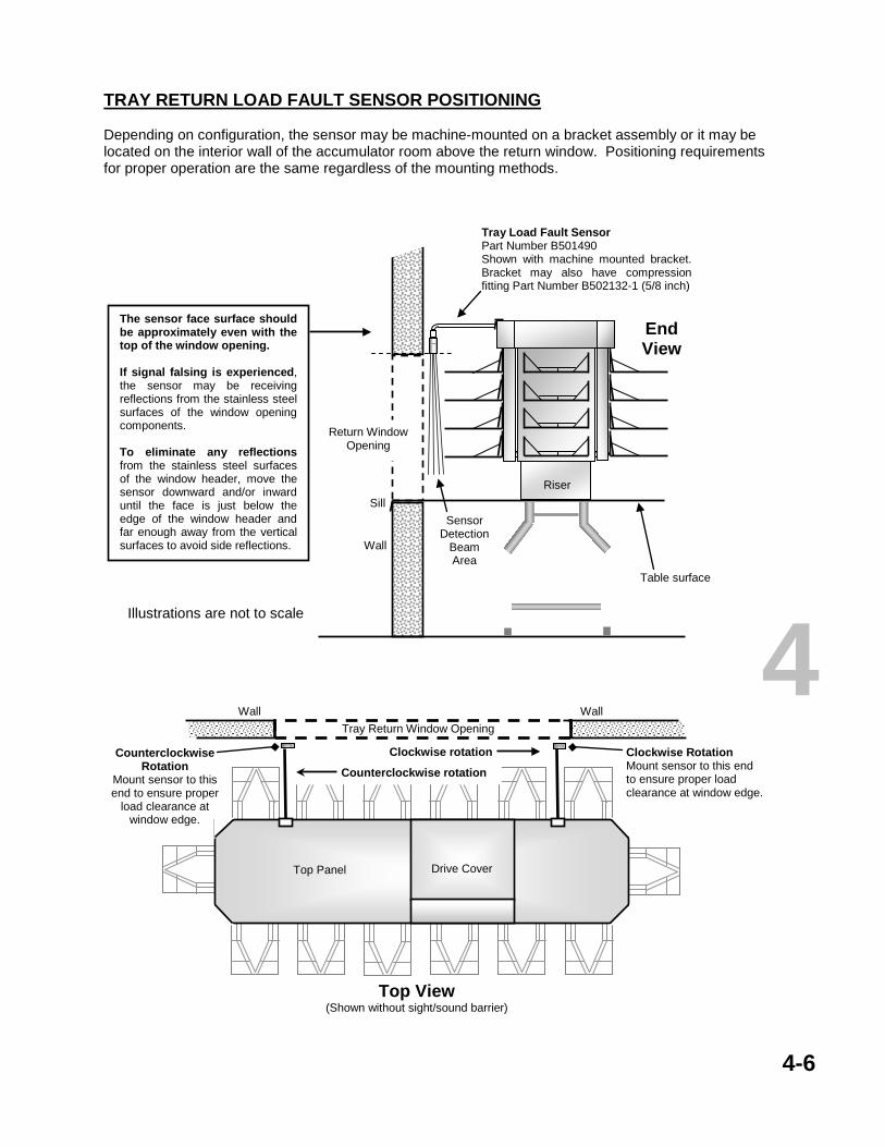
4-6
TRAY RETURN LOAD FAULT SENSOR POSITIONING Depending on configuration, the sensor may be machine-mounted on a bracket assembly or it may be located on the interior wall of the accumulator room above the return window. Positioning requirements for proper operation are the same regardless of the mounting methods.
Clockwise Rotation Mount sensor to this end to ensure proper load clearance at window edge.
Wall
Tray Return Window Opening
Wall
Top Panel
Top View (Shown without sight/sound barrier)
Counterclockwise Rotation
Mount sensor to this end to ensure proper
load clearance at window edge.
Counterclockwise rotation
Clockwise rotation
Drive Cover
Illustrations are not to scale
Tray Load Fault Sensor Part Number B501490 Shown with machine mounted bracket. Bracket may also have compression fitting Part Number B502132-1 (5/8 inch)
Sensor Detection
Beam Area
Return Window Opening
Wall
End View
Table surface
The sensor face surface should be approximately even with the top of the window opening. If signal falsing is experienced, the sensor may be receiving reflections from the stainless steel surfaces of the window opening components. To eliminate any reflections from the stainless steel surfaces of the window header, move the sensor downward and/or inward until the face is just below the edge of the window header and far enough away from the vertical surfaces to avoid side reflections.
Riser
Sill
4

OPERATION ACCUMULATOR CONTROLS The Accumulator control panel should be located near the first work station for convenience and safety concerns. The panel may also contain the controls for more than one conveyor. Consult the instructions for each type of conveyor for the respective details of operation.
• Optional Conveyor START-STOP Stations Depending on system layout and options chosen, there may be optional START-STOP stations located at work stations. Each START-STOP station will operate only one conveyor system.
• Optional Conveyor Advance Switches for any accompanying belt conveyors.
If one or more belt conveyors are supplied to carry soiled dishes away from the accumulator, these conveyors can run automatically or may be equipped to operate only on demand. See the operating instructions for the particular conveyor for more information.
• Tray Loading Sensor A sensor is placed above the tray return window area to detect improperly loaded trays or obstructions in the carrier basket path. When an improperly positioned object comes into the range of the sensor, the accumulator drive circuit is interrupted and the accumulator stops. When the obstruction is removed, the drive signal is restored and the accumulator resumes operation.
Tray Loading The wireform carrier baskets are designed for ONE (1) tray only. The practice of loading the carrier baskets with more than one tray at a time will cause the loading to be unstable, will encourage further overloading, and will only increase the ware handling time. More importantly, overloading will compromise the drive system performance. Conveyor Speeds Work station dwell time and system accumulation capacity along the routes of the various conveyors will be factors in determining the most efficient speeds for the conveyors. The variable speed feature of the conveyors will allow the conveyor speeds to be set to match work station demand and to avoid ware handling jams. Conveyor Shut-off and Conveyor Jam Switches for any accompanying conveyors. Rotary tray accumulators can be accompanied by belt conveyor systems that carry the soiled dishes away from the accumulators after scrapping. The conveyors can be equipped with optional conveyor jam switches and conveyor shut-off switches. The switches can take the form of an electronic or optical sensor, or they may be a simple mechanical lever limit switch type.
• Conveyor Shut-Off switches will stop the particular conveyor when a rack or dish moves past the sensor or contacts the shut-off bar. This arrangement allows the personnel time to accomplish a task before restarting or advancing the conveyor. To restart the system, clear the shut-off switch and press the START pushbutton, or press and hold the Conveyor Advance pushbutton (if equipped) until the next objects reach the work station.
• Conveyor jam (if equipped) switches will allow the passage of articles which are in proper position
on the conveyor but will stop the conveyor when an object or a carrier that is out of place passes the sensor or contacts the switch lever or bar. To restart the conveyor, clear the obstruction and press the START pushbutton or the Conveyor Advance pushbutton (if equipped).
4-7
4

BASIC OPERATOR PANEL
There may be controls for other conveyors located on this panel. Shown below is the basic control configuration for the Rotary Tray Accumulator. Consult the operating instructions for any other conveyors that may be controlled from this panel.
4-8
START
STOP
MAIN DISCONNECT
TRAY LOAD FAULT
CARRIER JAM
SPEED
GREEN
RED
This pushbutton STARTS the accumulator.
Always make sure that the conveyor is clear to operate before pressing this button!!! Secure all scrap pans and trays in place and close all access doors before starting any conveyor. Failure to do so could result in injury or damage or both. Optional remote operator stations for this conveyor operate in the same manner.
This pushbutton STOPS the
accumulator.
RED pilot lamp indicates when the accumulator is activated.
Speed control allows the operator to vary the speed of the accumulator to accommodate system loading.
CIRCUIT BREAKER Turns ON main power to all the components in the control cabinet.
OPTIONAL* RED pilot lamp indicates there is something physically interfering with the accumulator operation and that the conveyor has stopped. Clear the problem and press the START button if necessary to resume operation.
Multiple conveyors with optional controls for both
Multiple conveyors with optional controls for primary
RED pilot lamp indicates a tray loading problem or other obstruction on the tray return side of the accumulator and that the conveyor has stopped. The sensor is located inside the upper portion of the return window frame. Clear the fault and the conveyor will resume operation.
Typical Conveyor Control Panel Layouts
Conveyor Manual Advance Station
Remote START-STOP
4

CLEANING THE ACCUMULATOR For proper sanitation and good maintenance practices, the accumulator and accompanying tables and troughs should be cleaned at the end of every work shift and readied for the next. The cleaning process offers a good opportunity to inspect and make note of any maintenance issues that may occur. CAUTION! Solutions used during the warewashing or cleaning processes should be regularly checked for pH levels. Any pH value below 4.5 or above 9.0 will damage the stainless steel and plastic parts of the machines. Solutions containing chlorine, ammonia, or phosphoric acid are not recommended. If it is necessary to use a strong solution to clean the surfaces, the residue should be thoroughly flushed away from all surfaces and components immediately, and the surfaces should be wiped down with a soft cloth to prevent damage to the components and to avoid water spotting. CLEANING PROCEDURES Do not apply a direct hose spray to any of the accumulator surfaces above the top level of the carrier panel surfaces as the water may enter or splash up into the drive system.
• Remove the wire carrier baskets from the carrier panels as necessary and clean them with soap and water to remove any food particles and debris. Rinse the wire baskets with plenty of clean water and allow them to dry in a clean location.
• Use a soft wet cloth and soap and water to thoroughly clean the carrier panels in place. Lightly
rinse away any soap or cleaning solutions with a gentle hose stream to the carrier panels from an angle above the top of the panels.
• Use a gentle hose stream to wash debris from the bearing areas on the carrier panel roller
assemblies. • Thoroughly clean and rinse the accumulator table and window sill pan.
• Thoroughly clean and rinse the overshelf units, scrapping tables and troughs. Perform the proper
cleaning procedures on other conveyors, tables, and accessories in the system, such as disposal units and pulpers according to the manufacturers’ recommendations.
• Remove any standing water on the table surfaces. If you have used any cleaning solutions in the
process, be sure to remove any remaining traces or damage and spotting will occur.
• Wipe down all the cleaned conveyor and table and accessory surfaces with a clean cloth that is sufficiently dry as to not leave streaks and spots.
• Place the wire carrier baskets back on the carrier panels when the cleaning process is completed.
4-9
4
!

ACCUMULATOR MAINTENANCE AND CARE The accumulator is relatively maintenance free, and unless a problem is indicated, a complete maintenance inspection every six months and proper lubrication is all that is required. Keeping the accumulator clean goes a long way toward extending the service life. DAILY At the end of the workday, check the accumulator for any signs that maintenance might be required, and look to see that there are no damaged or worn components. If there are any unusual noises or operating malfunctions with the accumulator, report them to maintenance personnel as soon as possible for inspection. Follow the cleaning recommendations in the Cleaning section of this manual. EVERY SIX (6) MONTHS
• Remove the accumulator’s drive cover and inspect all the components of the drive system for wear or damage. Replace any worn parts as soon as possible since worn components will accelerate wear on the other system components and increase operating expenses.
• Check the drive motor and gearbox for accumulated dust and obstructed ventilation passages.
Remove any oily residue and dust from the exterior of the motor. Oily residue will cause dust to build up and potentially block proper ventilation. If leakage is found, make a determination of the source and whether or not any major maintenance is needed.
• Inspect the drive chain, the sprockets and dogs, the caterpiller chain tension, and conveyor track for wear. Proper chain tension is set during factory assembly and should need no further adjustments.
• The caterpillar chain should require little or no resetting of tension. Do not run the accumulator
with a chain that is too loose or too tight. Doing so will inhibit proper accumulator operation and will cause severe damage to the drive system and tracking components. Contact Bi-line Service before attempting to reset chain tension. A loose chain may indicate a drive system problem.
• Drive chain lubrication done at the factory should be sufficient for most applications. Any
lubricating of the chain in service should be limited. Contact Bi-line Service before lubricating the Drive Chain or the Caterpiller Chain.
• Check for and properly tighten any loose fasteners, and replace any missing fasteners.
TYPICAL LUBRICANTS for all gearboxes Oils VG220, CLP 220, PGLP 220, and PGLP 460 complying with DIN 51502 and 51517 are suitable. DO NOT MIX OIL TYPES! Suggested oils for all gearboxes Mineral oils: Shell Omala EP220 or equivalent Synthetic oils: Shell Omala HD220 or equivalent NOTE! DO NOT MIX OIL TYPES in service or as waste! Synthetic oils with a polyglycol base (PGLP, etc.) must be kept separate from mineral oils and are to be disposed of as special waste.
4-10
4

4-11
CATERPILLER CHAIN
CONVEYOR TRACK
SIDE VIEW
CONVEYOR TRACK
TOP VIEW
DRIVE CHAIN
Side Guidance Wheel Twin Load Carrying Wheels
Drive Chain
Drive Chain Dog
CHAIN TENSION Grasp pendant between thumb and forefinger at least 2 feet past the drive in the direction of travel and pull back and forth. Proper tension should permit approximately +/- 0.25 inch of movement. Call Bi-line Service before attempting to adjust the drive chain or the caterpiller chain.
Side Guidance Wheel
Twin Load Carrying Wheels
Pendant
Pitch 6 inches
4

4-12
4 CONTROL CABINET INTERIOR COMPONENTS – General Configuration Shown is a general layout of components and their approximate locations. The number and types of components and the presence of timers will vary with conveyor types, system configurations, and optional equipment. Not all components shown will be present in all configurations.
Control Transformer 230V P/N B500104 460V P/N B502471
Terminal Blocks
Fuse Blocks 250V Part Number B500793 600V Part Number B500792
Fuses for 24 Volt 1 amp P/N B500801 2 amp P/N B500802 Fuses for 600 Volt 1 amp P/N 112901 10 amp P/N 100913
Relay Sockets, each Part Number B500598
Relays, each 24VAC 4Pole
Part Number B500604
AC Variable Speed Drive 1
Motortronics
230V P/N B501018 460V P/N B502467
Mitsubishi 230V P/N B502437
AC Variable Speed Drive 2
If equipped, see Drive 1 for part
numbers.
Repeat Cycle Timer Part Number B500608 Timer Socket (not shown) Part Number B500599
Base electrical cabinet BOM numbers are B701354 for 18 inch, and B701355 for 24 inch.
START
STOP
Green Push
Button
Red Push
Button
Conveyor Manual Advance Station Palm Switch Assembly Part Number B501611 Enclosure Part Number B502283
230V CIRCUIT BREAKER/DISCONNECT Part Number B500138 230V COVER BOOT Part Number B500338
480V DISCONNECT OPERATOR (on door) Part Number B500621 480V DISCONNECT, 4 pole (inside cabinet) Part Number B500622
PILOT LAMPS, each Part number B502176
GREEN PUSH BUTTON Part Number B502109 CONTACT BLOCK N.O. Part Number B502107 RED PUSH BUTTON Part Number B502110 CONTACT BLOCK N.C. Part Number B502108
CONTACT BLOCK MOUNTING ADAPTER (not shown) 1 required per pushbutton Part Number B502106 Remote START-STOP enclosure (not shown) Part Number B502284
SPEED CONTROL Single Conveyor ……………………….. Part Number B501158 Two Conveyor, single control Knob …. Part Number B501224 Knob only ……………………………….. Part Number B501158-1
OR
CONTROL PANEL COMPONENTS NOTE! The actual layout and quantity of control components will vary with the configuration of the conveyor system, the number of conveyor drives, and the options installed. Pushbutton parts also used in Remote START-STOP Stations.

4-NOTES Update control panel information and add part numbers. Replace old style accumulator section with new style.
3765 Champion Blvd Winston-Salem, NC 27115
(336) 661-1951 (800) 383-5933 Fax (336) 661-0498
2674 N. Service Road Jordan Station, Ontario, Canada L0R 1S0
(905) 562-6630 Fax (905) 562-5422
4
SLAT and KNUCKLE BELT CONVEYORS
OPERATION AND MAINTENANCE MANUAL INSTALLATION Page Return Monorail ………………………………………………………………………………… 5-1 OPERATION Control panel layout …………………...………………………………………………………. 5-2 Operation ……………………………………………………………………………………….. 5-3
CLEANING Cleaning and precautions ……………………………………………………………………… 5-4 MAINTENANCE Conveyor types and parts ……………………………………………………………………… 5-5 Drive cabinet and wash chamber ……………………………………………………………... 5-7 Belt wash system ……………………………………………………………………………….. 5-10 Control panel and electrical cabinet parts ……………………………………………………. 5-11 Gearmotor maintenance ……………………………………………………………………….. 5-12
Note: Electrical schematics are stored in the electrical cabinet and should remain there for use by service personnel.
3765 Champion Blvd
Winston-Salem, NC 27115 (336) 661-1951 (800) 383-5933
Fax (336) 661-0498
2674 N. Service Road Jordan Station, Ontario, Canada L0R 1S0
(905) 562-6630 Fax (905) 562-5422
5

SLAT BELT and KNUCKLE BELT CONVEYORS Use the P&E drawings to identify all the components in the system, their orientations to each other, and verify how all the components fit together. Check the dimensions of the space and compare it to the P&E drawings. If there are discrepancies, notify Bi-line immediately before going further.
Return Monorail Installation for US versions - Follow the INSTALLATION OVERVIEW section for general instructions installation.
NOTE!
PO Box 16009 Winston-Salem, NC 27115 (336) 661-1951 Fax (336) 661-0498
READ THESE INSTRUCTIONS BEFORE INSTALLING OR OPERATING THE CONVEYOR SYSTEM!
5-1
¼-20 Hex X 2
¼-20 Hex X 2
¼-20 Weld Nut
X 2
¼-20 Weld Nut
X 2
3 3/16 inch max
#8 x ½ Sheet metal
Screws X 4
#8 x ½ Sheet metal
Screws X 2
#8 x ½ Sheet metal
Screws X 2
3/8 inch holes x 4 for mounting to studs on bottom of channel
Canadian version shown on next page
Table Surface
Monorail Channel Bracket
Monorail Guide Bracket
CROSS SECTION END VIEW Flex Belt Slat
Chain
*White UHMW Plastic Guide
(Straight section)
Flex Belt Slat
Chain
#8 x ½ Sheet Metal Screws
#8 x ½ Sheet Metal
Screws
*White UHMW Plastic Guide
*White UHMW Plastic Guide
(Straight section)
Slat wing travels on the UHMW guide, not on table surface.
*NOTE: This type of UHMW plastic guide is also used on the table surface in turns to trap the belt and ensure that it moves without corner binding. Due to the custom nature of the applications, there may be other types of bracketry in place along with those shown above. Units manufactured in our Canadian facility may differ slightly from these illustrations. For all replacement guides, brackets, and drain pan parts, call Bi-line Service.
5

Return Monorail Installation, cont. OPERATION - There may be controls for other conveyors located on this panel. Shown below are the basic control configurations. Consult the instructions for any other conveyors that may be controlled from this panel. Before starting the conveyor,
• Turn on the main disconnect switch on the control panel • Open any drain valves as necessary • Open any water shutoff valves as necessary • Check detergent solution level • Make sure the conveyor system is clear to operate
5-2
Installation tips • All table sections must be properly aligned and leveled before the tables are joined or the belt will not track
properly and could jam. • Return track sections, especially turns, must be checked and properly aligned before the tables and tracks are
joined. • The return drain pan sections must be properly aligned under the return track and lapped in the direction of the
flow (toward the tail tank) or the pans will leak. Each succeeding return pan section should be lapped under the preceding section and sealed.
• Apply silicone sealant to the lapped ends where necessary at final fitting, assemble, and allow the sealant to
cure before start-up begins. Don’t forget! Before you set the conveyor in its final location,
• Are there any utility connections, switches, covers, or other components that mount on the wall side that need to be in place?
• Has sealant been applied where necessary in places that will not be accessible once set in place?
• Have all components supplied by others that are to be fitted to the conveyor system before it is set in place been
completed?
Multiple conveyors with optional controls for both
Multiple conveyors with optional controls for primary
Conveyor Manual Advance Station
Typical Conveyor Control Panel Layouts
Continued on next
page
Canadian versions
Bolt ¼-20 x ¾
SS
Curve Belt Guides – 1 each required Inside curve Part Number BC04482 Outside curve Part Number BC04483
Spacer
P/N BC04484
A Top Track Guide – Straight Part Number BC04481 B Return Track Guide – Straight Part Number BC04480
Slat
A A
B B
Table surface
5

OPERATION, cont. Before beginning operation, read this page carefully!
5-3
Manual Advance Station. These stations are usually positioned at workstations along the conveyor route. The conveyors controlled by these stations will advance only as long as the black pushbutton is pressed. To operate, press the green START pushbutton for that conveyor on the main panel or a remote START-STOP Station to enable the conveyor, then press one of the black conveyor advance pushbuttons to advance the conveyor. Note: The belt wash and rinse systems (if equipped) on these conveyors will operate only while the advance pushbutton is being pressed.
Optional Remote START-STOP stations may be located at any point along the conveyor route. The START-STOP switches operate in the same manner as the START-STOP switches on the main control panel. For Manual Advance conveyors, the START switch on the main panel or on the Remote station must be pressed before the black pushbutton on the Manual Advance Station will advance the conveyor. STOP
START
MAIN DISCONNECT
SPEED*
START
STOP
RINSE WASH ACCUMULATION
Green Push
Button
Red Push
Button
OPTIONAL* Speed Control allows the operator to vary the speed of the conveyor to meet system loading.
RED Pilot Lamp Indicates the conveyor is activated
This pushbutton STOPS the conveyor
RED Pilot Lamp (if equipped) Indicates the Accumulation Switch has been activated.
RED Pilot Lamp Indicates the Belt Wash Timer is activated.
CIRCUIT BREAKER Turns main power ON and OFF to the control system and the drive
motors.
5
RED Pilot Lamp Indicates the Belt Rinse is activated.
This pushbutton STARTS the conveyor. Always make sure the conveyor is clear to operate before starting!!! Secure all removable scrap pans and screens in place and close all access doors before starting the conveyor. Failure to do so could cause injury or damage or both. For Manual Advance conveyors, the START switch on the main panel or on the Remote station must be pressed before the black pushbutton on the Manual Advance Station will advance the conveyor. See Manual Advance Station below.
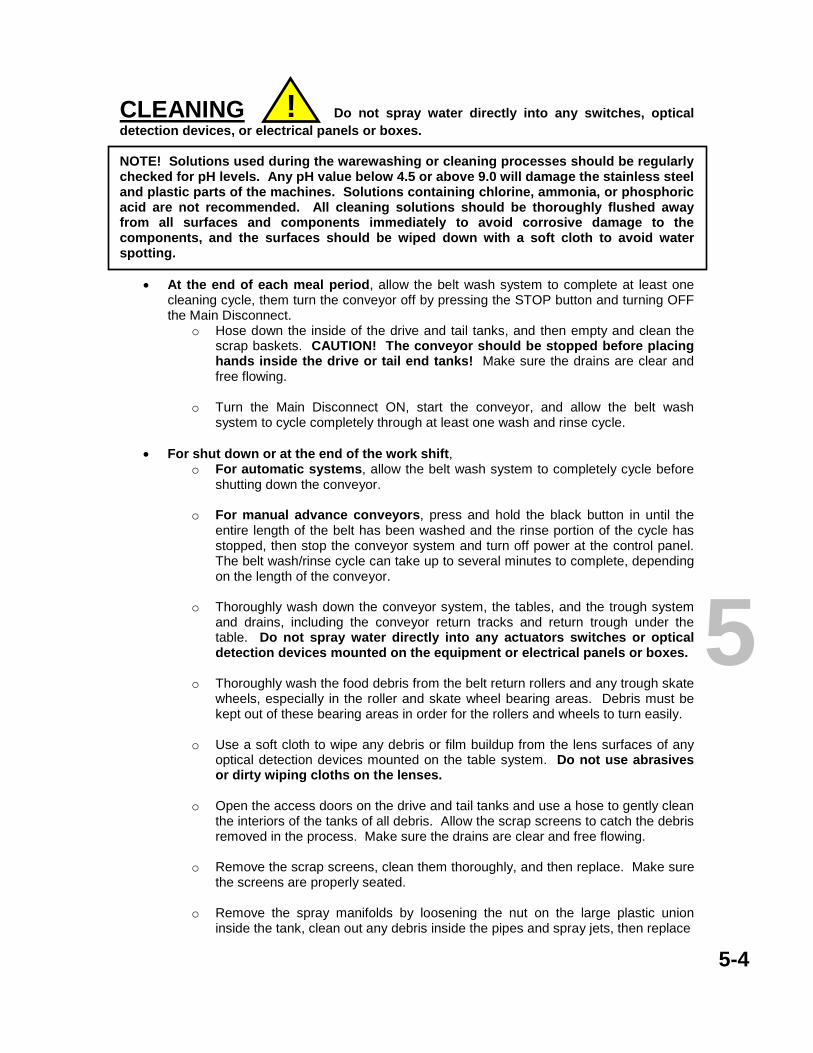
CLEANING Do not spray water directly into any switches, optical detection devices, or electrical panels or boxes. NOTE! Solutions used during the warewashing or cleaning processes should be regularly checked for pH levels. Any pH value below 4.5 or above 9.0 will damage the stainless steel and plastic parts of the machines. Solutions containing chlorine, ammonia, or phosphoric acid are not recommended. All cleaning solutions should be thoroughly flushed away from all surfaces and components immediately to avoid corrosive damage to the components, and the surfaces should be wiped down with a soft cloth to avoid water spotting.
• At the end of each meal period, allow the belt wash system to complete at least one
cleaning cycle, them turn the conveyor off by pressing the STOP button and turning OFF the Main Disconnect.
o Hose down the inside of the drive and tail tanks, and then empty and clean the scrap baskets. CAUTION! The conveyor should be stopped before placing hands inside the drive or tail end tanks! Make sure the drains are clear and free flowing.
o Turn the Main Disconnect ON, start the conveyor, and allow the belt wash
system to cycle completely through at least one wash and rinse cycle.
• For shut down or at the end of the work shift, o For automatic systems, allow the belt wash system to completely cycle before
shutting down the conveyor.
o For manual advance conveyors, press and hold the black button in until the entire length of the belt has been washed and the rinse portion of the cycle has stopped, then stop the conveyor system and turn off power at the control panel. The belt wash/rinse cycle can take up to several minutes to complete, depending on the length of the conveyor.
o Thoroughly wash down the conveyor system, the tables, and the trough system
and drains, including the conveyor return tracks and return trough under the table. Do not spray water directly into any actuators switches or optical detection devices mounted on the equipment or electrical panels or boxes.
o Thoroughly wash the food debris from the belt return rollers and any trough skate
wheels, especially in the roller and skate wheel bearing areas. Debris must be kept out of these bearing areas in order for the rollers and wheels to turn easily.
o Use a soft cloth to wipe any debris or film buildup from the lens surfaces of any
optical detection devices mounted on the table system. Do not use abrasives or dirty wiping cloths on the lenses.
o Open the access doors on the drive and tail tanks and use a hose to gently clean
the interiors of the tanks of all debris. Allow the scrap screens to catch the debris removed in the process. Make sure the drains are clear and free flowing.
o Remove the scrap screens, clean them thoroughly, and then replace. Make sure
the screens are properly seated. o Remove the spray manifolds by loosening the nut on the large plastic union
inside the tank, clean out any debris inside the pipes and spray jets, then replace
5-4
5
!

Cleaning, continued the spray pipes. Do not over-tighten the nut when replacing the manifold.
o Wipe the table surfaces down with a soft clean cloth to prevent spotting.
CONVEYOR SLATS and LINKS CAUTION! Strong solutions used during the warewashing or cleaning processes should be regularly checked for pH levels. Any pH value below 4.5 or above 9.0 will damage the stainless steel and plastic parts of the machines. If it is necessary to use a strong solution to clean the surfaces, the residue should be thoroughly flushed away from all surfaces and components immediately, and the stainless surfaces should be wiped down with a soft cloth to prevent damage to the components and to avoid water spotting. The conveyor slats can be removed and replaced without having to remove the conveyor from the tables. Damaged and sufficiently warped slats can cause cutlery and flatware to catch and damage other slats and components in the system and should be replaced as soon as possible. Pin and Slat type The pin type slat is directional and is designed primarily for straight conveyor runs. The belting is available in various widths and is constructed from HDF plastic slats connected together with stainless steel pins. Type HDF plastic is a low-friction wear-resistant and self lubricating material that does not require maintenance beyond cleaning. The undersides of the slats are marked OUT x and IN. The symbols indicate the direction that the pins should be installed and removed, and the lines on the “IN” symbol indicate the splined end of the pin. Remove the pins from the affected slats and the adjoining slats as necessary by placing a small straight punch into the “OUT” end of the pins and tapping the punch with a hammer to drive the splined portion of the pin out of the slat. To install the pin, insert the pin into “IN” side of the slat and tap into position until the pin is fully seated.
5-5
TOP VIEW
Observe travel direction as marked on the bottom side of each slat!
Replacement Slat Belt Sections Includes chain - specify length 7.5 inch Part Number B500373 10 inch Part Number B500377 12 inch Part Number B500375
OUT IN TRAVEL
BOTTOM VIEW
Replacement Slats 7.5 inch Part Number B500373-1 10 inch Part Number B500377-1 12 inch Part Number B500375-1 5

Chain and Slat type To replace the slats, place the portion of the chain where the slat is to go on a solid surface or object small enough to fit between the tabs on the slat. Do not use anything under the chain that has sharp or pointed surfaces that could dent, scratch, or damage the conveyor table or damage the chain. Align the clearanced areas in the slat with the pins on the chain and use the heel of your hand to give the top of the slat a sharp smack to seat the slat onto the chain pins.
Knuckle Belts The knuckle belt conveyor has two types of plastic knuckle links connected together with stainless steel knuckle pins. The pins are spline punched on the ends to grip the inside of the hole for the pin in the plastic link. The tabbed “drive” links are the same design as the knuckle links with the addition of a raised tab on the top side that contacts with the lower edge of the rack and pulls or pushes the racks along the conveyor surface. Drive link spacing will vary with the customer requirements. If it is necessary to separate the links, the pins can be driven out with a punch and a small hammer. When re-installing the pins, it is suggested that you make sure the pins are rotated in the holes so that the punched edges of the pin do not line up with any previous score marks.
5-6
SIDE VIEW
Standard Link Pin
Knuckle belt Part Number B504433 – specify the length and the number of standard links between knuckle links or the distance in inches between knuckles.
Link with Drive Tab Tab
Standard Link
5
TOP VIEW
SIDE VIEW
Guide Tabs
Replacement Slats, each Complete Belt, per ft specify length 7.5 inch Tapered Part Number B502409-1 7.5 inch Part Number B502409 10 inch Tapered Part Number B501961-1 10 inch Part Number B501961 10 inch K-slat Part Number B700262-1 10 inch Part Number B700262 12 inch Tapered Part Number B504460-1 12 inch Part Number B504460 If replacing belt sections, two (2) master links Part Number B501252 will be required.
Illustrations are not to scale
*Belt Chain
Do not lubricate the belt chain! It is designed to run “clean” to meet health and sanitary regulations.
Chain Slat FRONT VIEW
Guide Tab
BOTTOM VIEW Illustration is not to scale *Belt Chain Do not lubricate! It is
designed to run “clean” to meet health and sanitary regulations.
GUIDE TAB Retains the slat through the turns and in the return guides sections.
To remove a slat from the chain, place small screw drivers here in relief areas in the guide tab and pry tabs away from each chain pin
Tapered slat shown

DRIVE CABINET and WASH CHAMBER with SCRAP BASKET Components will be reversed between Right-to-Left and Left-to-Right configurations
5-7
*Belt Return Roller, rubber coated or SS. Some systems may have custom components and roller lengths and materials may vary accordingly. Measure carefully and confirm the length before ordering replacements Call Bi-line Service with roller dimensions and job name when necessary.
Plastic Plug ½ inch (not shown) 4 each required ………… Part Number 108418 Plastic Plug Nut, (not shown) 4 each required ……………. Part Number 108417 Fiber Washer, (not shown) 4 each required ……………….. Part Number 109034 Magnetic Door Catch (not shown) 2 per cabinet ……..…… Part Number 109988 Scrap Screen, 1 inside each tank. See Cleaning instructions Dual 7.5 and 10 inch Part Number B701802-1 Single 12 inch Part Number B701802-2 Single 7.5 and 10 inch and Knuckle Belt conveyors Part Number B701802-6
Chain Tensioner & UHMW Wear Block
The Drive Chain should be checked for tension monthly and lubricated at least twice yearly. See Maintenance Schedule, Page 9. Do not lubricate slat belt chain. It is designed to run “clean” to meet health & sanitary regulations. Tensioner Guide Block Part Number B300085 Tensioner Bracket Part Number B300084
Drive Chain, sold per foot Part Number B500754S Master Link, 1 per chain Part Number B500380S Half Link, 1 per chain Part Number B503059
Drain Assembly Part Number 0503928
Drive Chain Sprocket, 2 per conveyor Part Number B500276-S Shaft Key, SS (not shown) 1 per sprocket Part Number B301060 *Belt Return Roller (inside tank, not shown) 12.25 inch Part Number B701142-10R 12.00 inch Part Number B701142-12R 23.25 inch Part Number B701142-21R Bearing Part Number B500295
See Belt Wash section for description and maintenance information for the belt wash
system.
Gearmotor, 230VAC Part Number B503784 See Gearmotor Maintenance Section
See Belt Drive Shaft Assembly
Page 8
Guide Block
TANK Adjust
Bracket
Proper tension is 1/2 to 5/8 inch of slack on the side opposite the chain guide block.
Access Door
Latch
Scrap Screen, 1 inside each tank. Part Numbers listed below.
See daily cleaning instructions.
5 Magnetic Reed Switch for Anti-Jam Switch on Slat Conveyors (Hamlin Mfg.) Part Number 111090-1
Mounted in the drive cabinet above the upper sprocket.
Magnet for Hamlin switch, Part Number B500260 Magnet mounts on underside of the anti-jam plate here on the end closest to the drive chain cabinet.
Anti-Jam Plate For 7.5 or 10 inch single belt Part Number B701445-S10 For 12 inch single belt Part Number B701445-S2 For Dual 7.5 or 10 inch belts Part Number B701445-D10

DRIVE CABINET and WASH CHAMBER, cont.
5-8
5
Chain and Slat Drive Sprocket 1 per shaft single belt, 2 per shaft double belt Part Number B501845 (US) Part Number BC04491 (Can.) Knuckle Belt Drive Sprocket Part Number B504434
Sprocket and key, see Page 7 Bearing, 2 per shaft Part Number 109958-S (US) Part Number BC04486 (Can.) Gasket, 2 per shaft (not shown) Part Number 104638 V-ring Seal, 2 per shaft (not shown) Part Number 109743
Drive Shaft Chain & Slat and Knuckle Belts Length* Part Number US models 17 inch B500735 19 inch B500735-2 28 inch B500735-3 Canadian BC04492
Pin & Slat Belt Drive Sprocket, 2 pieces 1 per shaft single belt, 2 per shaft double belt Part Number B500669 Sprocket Key (not shown) Part Number B301060 Bearing, 2 per shaft
Part Number 109958-S Gasket, 2 per shaft (not shown) Part Number 104638 V-ring Seal, 2 per shaft (not shown) Part Number 109743
Pin and Slat Belt Drive Shaft Length* Part Number 17 inch B500735 19 inch B500735-2 28 inch B500735-3
Drive Shaft
Chain and Slat Belt Tail (Idle) Sprocket, 1 per single belt, 2 per dual belt Part Number B501845-1 (US) Part Number BC04497 (Can.)
Tail (Idle) Shaft Length* Part Number 12 inch B300937 19 inch B300937-1 23 inch B300937-5 18 inch B300937-6 Canadian BC04496
Collars, 2 required Part Number 104713
Knuckle Belt Tail (Idle) Sprocket Part Number B504435
For models equipped with shaft bearings, use P/N 109958 Canadian built models use Part Number BC04494
Bearing Journals, 2 required Part Number B500317
Tail (Idle) Shaft
Sprocket Key (not shown) P/N B301060
Drive Shaft
For other shaft lengths, call Bi-line Service with dimensions and job name.
NOTE! Shaft bearing assemblies are equipped with Zerk type grease fittings and should be checked and lubed at least twice yearly with a multi-purpose grease.
*For other shaft lengths, call Bi-line Service with dimensions and job name.
Sprocket and key, see Page 7
Pin and Slat Belt Tail (Idle) Shaft Length* Part Number 17.00 inch B301766 10.25 inch B301766-1 14.00 inch B301766-2
Tail (Idle) Sprocket, 2 piece 1 per shaft single belt, 2 per shaft double belt Part Number B500664
13.00 inch B301766-4 16.25 inch B301766-7 12.25 inch B301766-5 21.25 inch B301766-6
Collars, 2 required Part Number 104713
Tail (Idle) Shaft
For models equipped with shaft bearings, use P/N 109958 Canadian built models use Part Number BC04494

DRIVE SYSTEM MAINTENANCE SCHEDULES Weekly
• Check all slats or knuckles for proper position and condition. Replace any missing or broken or damaged slats as soon as possible.
• Check for any abnormal noises, belt misalignments, loose fasteners, and operator reports
of malfunctions.
• Check for and remedy any water leaks in the plumbing, the table systems, or the accessories.
• Inspect the condition of the controls and check for proper operation.
Monthly
• In addition to the Weekly maintenance inspections, check the flex belt chain tension. While the factory setting for tension is intended for long term service, as with all mechanical devices, the chain and sprockets and guides will require maintenance inspections at regular intervals. If the belt does not track properly, especially in turns, it may be due to improper tension. Inspect the complete belt routing for evidence of wear or damage of the components or other causes and remedy the situation as soon as possible to avoid lengthy downtime and to reduce maintenance expenses.
• Open the drive cabinet and inspect the drive chain and sprockets for wear and tension,
then adjust if necessary. If the chain can no longer be adjusted within the range of the chain tensioner, replace the chain. If the tensioner block is worn, replace it. The Drive Chain should be lubricated at least twice yearly with a small amount of suitable multi-purpose grease. Wipe any excess off so as to prevent buildup of dust and debris.
• Do not lubricate the slat belt chain – it is designed to run “clean” to meet health
and safety laws and regulations. Every six (6) months
• Complete all the items in the weekly and monthly schedules and adjust or service as necessary.
• Check the gearmotor assembly as per the instructions in the Gearmotor Maintenance
section (Page 12).
• Inspect all the exposed drive system components for wear and lubrication and follow the maintenance guidelines for the components.
• Inspect the tables and base assemblies for position and condition. Take immediate
action on any components needing attention.
5-9
5

BELT WASH SYSTEM See also DRIVE CABINET and WASH CHAMBER The belt wash system has wash and rinse spray arms located in the wash chamber in the drive cabinet that operates automatically when the conveyor is activated. There is a scrap basket located in the drive tank that will need to be emptied and cleaned at least daily. The system utilizes a detergent pump mounted in the drive cabinet and controlled by a repeat cycle timer mounted in the control panel that is activated when the conveyor is activated. The Belt Wash System is fed by ½ inch cold and hot water lines entering the drive cabinet. Water temperature and pressure is controlled by a mixing valve (see diagram). The nominal rinse spray water pressure is 15-30 psi and the nominal water temperature is 100 degrees F (37 degrees C). Higher temperatures can cause warping of the belt slats. Use of chemicals with pH less than 4.5 or higher than 9 will damage the conveyor slats! When the wash timer is activated, the water solenoid valve is opened and the water is applied to both the wash and rinse spray arms. The detergent pump draws detergent from a remote container and injects it into the wash spray arm manifolds. When the wash portion of the cycle ends, the detergent pump stops and the water solenoid remains open for a period set by the timer for rinsing the detergent and debris from the belt. The usual timing is for one complete belt rotation in the wash mode followed by one complete rotation in the rinse mode. The timers can each be adjusted from 0.5 to 6 minutes. Note: Belt wash timers on Manual Advance Conveyors operate only when the black pushbutton on the Manual Advance Station is pressed. To complete a wash – rinse cycle, the Manual Advance pushbutton must be pressed and held for a period that will allow the system to complete two complete rotations.
5-10
Needle Valve, ¼ NPT Part Number 0502781
Vacuum Breaker, ¼ inch Part Number 107069 *Repair Kit for breaker* (not shown) Part Number 900836 Vacuum Breaker Bracket (not shown) Part Number B302025 Connector, 3/8 tubing to ¼ NPT Part Number B502032 Plastic Tubing, 3/8 inch Specify length Part Number B500741
Mixing Valve, 3/8 NPT Part Number B500743
Chemical Feed Pump Part Number
B500761 Nipple, ¼ NPT X 2 inch Part Number B500396
Solenoid Valve, ¼ inch Part Number B500537
Connector, ¼ NPT x 3/8 Part Number B502032
Brass Elbow, ¼ inch Part Number B500237 Brass Tee, ¼ inch Part Number B500236 Plastic Tee, ¼ inch Part Number B502033
Detergent Solution
Spray Pipe Fittings Part Number 0510881 Brass Reducing Bushing Part Number B501813 Stainless Adapter Part of Chemical Pump Plastic Connector Part of Chemical Pump
Located in lower portion of drive tank
Located on upper side
of tank
BELT WASH SYSTEM
Flow
Diagram and Parts List
Spray Pipe Kit, 2 per tank, includes nozzles Part Number B701983-4 Spray Pipe Nozzles, 3 per pipe (included in B701983-4) Part Number 0508376
Pump parts Part Number Motor B501342 Tube B501343 Rotor B501344 Plate B501345 Housing B501346 Transformer B501347
A
A
B
B
C
C
Hot and Cold Water Lines Adjust the Mixing Valve for a temperature of 100 degrees F (38 degrees C). Maintain 15-20 PSI minimum incoming flow pressure.
5

5-11
5 CONTROL CABINET INTERIOR COMPONENTS – General Configuration Shown is a general layout of components and their approximate locations. The number and types of components and the presence of timers will vary with conveyor types, system configurations, and optional equipment. Not all components shown will be present in all configurations.
Control Transformer 230V P/N B500104 460V P/N B502471
Terminal Blocks
Fuse Blocks 250V Part Number B500793 600V Part Number B500792
Fuses for 24 Volt 1 amp P/N B500801 2 amp P/N B500802 Fuses for 600 Volt 1 amp P/N 112901 10 amp P/N 100913
Relay Sockets, each Part Number B500598
Relays, each 24VAC 4Pole
Part Number B500604
AC Variable Speed Drive 1
Motortronics
230V P/N B501018 460V P/N B502467
Mitsubishi 230V P/N B502437
AC Variable Speed Drive 2
If equipped, see Drive 1 for part
numbers.
Repeat Cycle Timer Part Number B500608 Timer Socket (not shown) Part Number B500599
Base electrical cabinet BOM numbers are B701354 for 18 inch, and B701355 for 24 inch.
START
STOP
Green Push
Button
Red Push
Button
Conveyor Manual Advance Station Palm Switch Assembly Part Number B501611 Enclosure Part Number B502283
230V CIRCUIT BREAKER/DISCONNECT Part Number B500138 230V COVER BOOT Part Number B500338
480V DISCONNECT OPERATOR (on door) Part Number B500621 480V DISCONNECT, 4 pole (inside cabinet) Part Number B500622
PILOT LAMPS, each Part number B502176
GREEN PUSH BUTTON Part Number B502109 CONTACT BLOCK N.O. Part Number B502107
RED PUSH BUTTON Part Number B502110 CONTACT BLOCK N.C. Part Number B502108
CONTACT BLOCK MOUNTING ADAPTER, 1 required per pushbutton Part Number B502106 Pushbutton parts also used in Remote START-STOP Stations. Remote START-STOP enclosure P/N B502284
SPEED CONTROL Single Conveyor ……………………….. Part Number B501158 Two Conveyor, single control Knob …. Part Number B501224 Knob only ……………………………….. Part Number B501158-1
OR
CONTROL PANEL COMPONENTS NOTE! The actual layout and quantity of control components will vary with the configuration of the conveyor system, the number of conveyor drives, and the options installed.

5-12
Polycord Gearmotors and Power Roller Below-Table Gearmotors
MOTOR
GEARBOX
Output Shaft Bearing Plate
Vent Plug Fill Plug
Either side bearing plate
Drain Plug
Drain Plug
Not to scale
Recommended oil level
Motor and Gearbox painted white
CHECK THE MOTOR AND GEARBOX EVERY 6 MONTHS for leakage and oil level. Make sure the motor ventilation is not blocked with debris, lint, residue, etc. If adding oil, do not mix oil types. If changing the oil, flush the gearbox with petroleum oil until all traces of contaminants are removed. Replace the drain plug and fill to the proper level with the recommended oil and replace the fill plug. Do not overfill.
MOTOR
GEARBOX
Fill only to
recommended level.
Belt Conveyor Gearmotors
Not to scale
Recommended oil level is ¾ to 1 inch below plug. Do not over fill.
Motor and gearbox painted blue
Vent/Fill Plug
Gearmotor Service Intervals It is recommended that the gearbox oil be changed after the first 250 hours of operation, and thereafter every 10,000 hours for mineral oils, and every 20,000 hours for synthetics. Do not overfill.
TYPICAL LUBRICANTS for all gearboxes Oils VG220, CLP 220, PGLP 220, and PGLP 460 complying with DIN 51502 and 51517 are suitable. DO NOT MIX OIL TYPES! Suggested oils for all gearboxes Mineral oils: Shell Omala EP220 or equivalent Synthetic oils: Shell Omala HD220 or equivalent NOTE! DO NOT MIX OIL TYPES in service or as waste! Synthetic oils with a polyglycol base (PGLP, etc.) must be kept separate from mineral oils and are to be disposed of as special waste.
5

5-NOTES Revisions: May 31, 2006 Add information to Return Monorail page Update and add part numbers on drive sections to reflect Canadian-built machines. Consolidate drive shaft and sprocket drawings to one page. Revise maintenance instructions for clarity and add maintenance schedule page. Revise Control Panel section for clarity and add part numbers.
3765 Champion Blvd Winston-Salem, NC 27115
(336) 661-1951 (800) 383-5933 Fax (336) 661-0498
2674 N. Service Road Jordan Station, Ontario, Canada L0R 1S0
(905) 562-6630 Fax (905) 562-5422
5

3765 Champion Blvd Winston-Salem, NC 27115
(336) 661-1951 (800) 383-5933 Fax (336) 661-0498
2674 N. Service Road Jordan Station, Ontario, Canada L0R 1S0
(905) 562-6630 Fax (905) 562-5422
6
FABRIC BELT CONVEYORS OPERATION AND MAINTENANCE MANUAL
OPERATION Page Control Panel and Operation……………....................………………………. 6-1 CLEANING Instructions and precautions ....................................................................... 6-2 MAINTENANCE Conveyor Parts and Adjustments ................................................................ 6-3 Control Panel Components .......................................................................... 6-4 Belt Conveyor Gearmotor ............................................................................ 6-5 Note: Electrical schematics are stored in the electrical cabinet and should remain there for use by service personnel.

6-1
Manual Advance Station. These stations are usually positioned at workstations along the conveyor route. The conveyors controlled by these stations will advance only as long as the black pushbutton is pressed. To operate, press the green START pushbutton for that conveyor on the main panel or a remote START-STOP Station to enable the conveyor, then press one of the black conveyor advance pushbuttons to advance the conveyor. Note: The belt wash and rinse systems (if equipped) on manual advance conveyors operate only while the advance pushbutton is being pressed.
Optional Remote START-STOP stations may be located at any point along the conveyor route. The START-STOP switches operate in the same manner as the START-STOP switches on the main control panel. For Manual Advance conveyors, the START switch on the main panel or on the Remote station must be pressed before the black pushbutton on the Manual Advance Station will advance the conveyor. STOP
START
MAIN DISCONNECT
SPEED*
START
STOP
Green Push
Button
Red Push
Button
BELT CONVEYOR
OPTIONAL* Speed Control allows the operator to vary the speed of the conveyor to meet system loading.
This pushbutton STARTS the conveyor. Always make sure the conveyor is clear to operate before starting!!! Secure all scrap pans and screens in place and close and secure all access doors before starting the conveyor. Failure to do so could cause injury or damage or both. For Manual Advance conveyors, the START switch on the main panel or on the Remote station must be pressed before the black pushbutton on the Manual Advance Station will advance the conveyor. See Manual Advance Station below.
RED Pilot Lamp Indicates the conveyor is activated
This pushbutton STOPS the conveyor
RED Pilot Lamp (if equipped) Indicates the Accumulation or Table Limit Switch has been activated and the conveyor belt is stopped. When the switch arm is cleared, the conveyor will resume.
CIRCUIT BREAKER Turns main power ON and OFF to the control system and the drive
motors.
6
CONTROL PANEL AND OPERATION

CLEANING DO NOT SPRAY WATER DIRECTLY INTO ANY ACTUATOR SWITCHES, OPTICAL DETECTION DEVICES, OR ELECTRICAL PANELS OR BOXES. Strong solutions used during the warewashing or cleaning processes should be regularly checked for pH levels. Any pH value below 4.5 or above 9.0 will damage the stainless steel and plastic parts of the machines. If it is necessary to use a strong solution to clean the surfaces, all residue should be thoroughly flushed away from all surfaces and components immediately. Table surfaces should be wiped down with a soft cloth to prevent corrosive damage to the components and to avoid water spotting. Keeping the conveyor system clean is essential to proper operation and sanitation guidelines. For general cleaning,
• Clean stainless steel surfaces with a soft cloth and a mild detergent intended for use with stainless steel.
• Flush with clean water or wipe down with a clean wet cloth, and then wipe dry to avoid
streaking and spotting. • Chlorinated detergents and sanitizing agents will damage stainless steel unless
thoroughly flushed or wiped away. During the work periods, keep the conveyor relatively clean of accumulated debris.
At the end of each meal period or for shutdown, stop the system and turn the power switch off.
• Clean away any accumulated food debris from the table surface including the table surfaces under the belt.
• Clean both sides of the belting with a clean wet towel by gently wiping the belting as it
travels with the towel. Advance the belt as necessary to clean all the belt surfaces until the full length of the belt is cleaned.
• If the conveyor is equipped with optical detection devices, DO NOT USE ABRASIVES
OR DIRTY WIPING CLOTHS ON THE LENSES.
• Wipe the table surfaces down with a soft clean cloth to prevent spotting.
• Empty and clean the scrap screens and trays, if equipped.
6-2
6
!

6-3
6
Motor B500074
Gear Reducer B500957 Sprocket B501039-SS
Sprocket B501039-SS
Fabric Belt (per ft.) requires lacing 10 inch width ... B501220
R R
Chain SST B500285
Master link (not shown)
B501252
R
R
Table surface Table cut-out
Scrapper Drawer Chute B301294-10
Scrapper Drawer B301288
Belt Scraper B301293-10
Adjust drive chain tension by loosening the four fasteners on the gear reducer case and sliding gearmotor until there is approximately ½ inch of movement in the center of the longest straight section of the chain, then tighten fasteners. Make sure the gearmotor sprockets and drive pulley sprockets are properly aligned with the chain and with each other.
P
Table cut-out
SIDE VIEW
CONVEYOR PARTS AND MAINTENANCE ADJUSTMENTS
Drive Pulley Assembly........................ B500442 Shaft for 10 inch belt ............................ B301121-10 Bearing Journal .................................. B500317 Collar ................................................... 104713 Pillow Block (not shown) .................... B500219
Limit Switch (not shown) Limit Switch .......... B500629 Limit Switch Arm ... B303099
L
Conveyor Belt Take-up Assemblies Threaded Rod SST ............... 8300983 (1 per side) Plain Hex Nut SST ½ X 13 .... 104584 (1 per side) 1 inch Collar SST ................... 104713 (1 per side) Adjust belt tension at the Take-Up Assemblies by loosening the locknuts on each side of the Tail Pulley shaft and adjusting the nuts on the threaded rods to apply or release tension on the Tail Pulley (P). Proper tension should allow approximately 2 inches of belt lift in the center of the table top. NOTE: When adjusting the take-up, the pulley must be kept in proper alignment or the belt will not track properly in the center of the pulley. When the desired tension is reached and the pulley is properly aligned, secure the fasteners.
Tail Pulley Assembly .......... B500441 Shaft SST for 10 inch belt .... B301122-10 Bearing Journal SST .......... B500317 requires 2 Collar SST ........................... 104713 requires 2
T P
Belt Idler Roller 13 inch PVC B701005-12
11.25 inch SST
B701142-31
14.25 inch SST B701142-36
R
L T
Scrapper Drawer Slide (2 required) B301289-20

CONTROL CABINET INTERIOR COMPONENTS – General Configuration Shown is a general layout of components and their approximate locations. The number and types of components and the presence of timers will vary with conveyor types, system configurations, and optional equipment. Not all components shown will be present in all configurations.
Control Transformer 230V P/N B500104 460V P/N B502471
Terminal Blocks
Fuse Blocks 250V Part Number B500793 600V Part Number B500792
Fuses for 24 Volt 1 amp P/N B500801 2 amp P/N B500802 Fuses for 600 Volt 1 amp P/N 112901 10 amp P/N 100913
Relay Sockets, each Part Number B500598
Relays, each 24VAC 4Pole
Part Number B500604
AC Variable Speed Drive 1
Motortronics
230V P/N B501018 460V P/N B502467
Mitsubishi 230V P/N B502437
AC Variable Speed Drive 2
If equipped, see Drive 1 for part
numbers.
Repeat Cycle Timer Part Number B500608 Timer Socket (not shown) Part Number B500599
Base electrical cabinet BOM numbers are B701354 for 18 inch, and B701355 for 24 inch.
START
STOP
Green Push
Button
Red Push
Button
Conveyor Manual Advance Station Palm Switch Assembly Part Number B501611 Enclosure Part Number B502283
230V CIRCUIT BREAKER/DISCONNECT Part Number B500138 230V COVER BOOT Part Number B500338
480V DISCONNECT OPERATOR (on door) Part Number B500621 480V DISCONNECT, 4 pole (inside cabinet) Part Number B500622
PILOT LAMPS, each Part number B502176
GREEN PUSH BUTTON Part Number B502109 CONTACT BLOCK N.O. Part Number B502107
RED PUSH BUTTON Part Number B502110 CONTACT BLOCK N.C. Part Number B502108
CONTACT BLOCK MOUNTING ADAPTER, 1 required per pushbutton Part Number B502106 Pushbutton parts also used in Remote START-STOP Stations. Remote START-STOP enclosure P/N B502284
SPEED CONTROL Single Conveyor ……………………….. Part Number B501158 Two Conveyor, single control Knob …. Part Number B501224 Knob only ……………………………….. Part Number B501158-1
OR
CONTROL PANEL COMPONENTS NOTE! The actual layout and quantity of control components will vary with the configuration of the conveyor system, the number of conveyor drives, and the options installed.
6-4
6

Polycord Gearmotors and Power Roller Below-Table Gearmotors
MOTOR
GEARBOX
Output Shaft Bearing Plate
Vent Plug Fill Plug
Either side bearing plate
Drain Plug
Drain Plug
Not to scale
Recommended oil level
Motor and Gearbox painted white
CHECK THE MOTOR AND GEARBOX EVERY 6 MONTHS for leakage and oil level. Make sure the motor ventilation is not blocked with debris, lint, residue, etc. If adding oil, do not mix oil types. If changing the oil, flush the gearbox with petroleum oil until all traces of contaminants are removed. Replace the drain plug and fill to the proper level with the recommended oil and replace the fill plug. Do not overfill.
MOTOR
GEARBOX
Fill only to
recommended level.
Belt Conveyor Gearmotors
Not to scale
Recommended oil level is ¾ to 1 inch below plug. Do not over fill.
Motor and gearbox painted blue
Vent/Fill Plug
Gearmotor Service Intervals It is recommended that the gearbox oil be changed after the first 250 hours of operation, and thereafter every 10,000 hours for mineral oils, and every 20,000 hours for synthetics. Do not overfill.
TYPICAL LUBRICANTS for all gearboxes Oils VG220, CLP 220, PGLP 220, and PGLP 460 complying with DIN 51502 and 51517 are suitable. DO NOT MIX OIL TYPES! Suggested oils for all gearboxes Mineral oils: Shell Omala EP220 or equivalent Synthetic oils: Shell Omala HD220 or equivalent NOTE! DO NOT MIX OIL TYPES in service or as waste! Synthetic oils with a polyglycol base (PGLP, etc.) must be kept separate from mineral oils and are to be disposed of as special waste.
6
6-5

NOTES Fabric Belt section added February 5, 2008
3765 Champion Blvd Winston-Salem, NC 27115
(336) 661-1951 (800) 383-5933 Fax (336) 661-0498
2674 N. Service Road Jordan Station, Ontario, Canada L0R 1S0
(905) 562-6630 Fax (905) 562-5422

CONVEYOR TABLE PLUMBING AND ACCESSORIES
BASIC PLUMBING LAYOUT ………………………………………………… Page 7-1 MIXING VALVE DETAIL ……………………………………………………… Page 7-2 WASHDOWN HOSE AND RINSE SPRAY PLUMBING ………...…….….. Page 7-3 Rinse Spray Hose and associated parts Washdown Hose and associated parts TABLE FLUSHING DETAIL ………………………………………………….. Page 7-4 TROUGH ASSEMBLY DETAILS ………………………………..…………… Page 7-5 Trough Gusher detail Trough Accessories
3765 Champion Blvd Winston-Salem, NC 27115
(336) 661-1951 (800) 383-5933 Fax (336) 661-0498
2674 N. Service Road Jordan Station, Ontario, Canada L0R 1S0
(905) 562-6630 Fax (905) 562-5422
7

7-1
¾
See Trough Gusher Detail
Any additionally specified or required components such as Pressure Reducing Valves, Backflow Preventer Valves, Master Solenoid Valves, etc. should be installed in the area between the valve and the first branch.
See Table Flushing Detail
¾
¾
Mixing Valve
See Mixing Valve Plumbing Detail
¾
¾
Items in gray supplied by others unless otherwise
specified
Disposer
*½ inch solenoid
valve
S
¾
¾
Silencer
Valve
Valve
Customer Side
¾
See Trough Gusher Detail
¾
¾
¾
COLD
HOT
BASIC PLUMBING LAYOUT
*Some installations utilize the solenoid valve to supply both the Disposer and the Trough Gusher nozzle. This arrangement may be adequate if only one gusher nozzle is installed. Two gusher nozzles will likely require more flow than the ½ inch plumbing of the disposer is able to handle.
7

MIXING VALVE DETAIL (Drawings are not to scale)
Brass 3/8 NPTF to ½ NPTF
Adapter 0503801
½ NPTF Check Valve
112866
Brass 3/8 NPTM to
½ NPTM Reducing
Nipple 0502605
½ NPTF Check Valve
112866
Brass 3/8 NPTM to
½ NPTM Reducing
Nipple 0502605
Brass 3/8 NPT
Close Nipple 100998
Copper ½ F to ½ NPTM
Adapter 107448
CPVC Example ½ inch
Copper
Cut and insert ½ inch CPVC
pipe here
CPVC ½ F to ½ NPTM
Adapter B504654
CPVC ½ to ¾ Reducing Coupling or Reducing Bushing
Copper Example
MATCH A To Washdown Hose
and Rinse Spray Piping
Hot/Cold Mixing Faucet Part Number B500742
7
7-2

WASHDOWN HOSE & RINSE SPRAY PLUMBING
SST ¾ NPTF Coupling 100044
Brass ¾ NPTM to ½ NPTF Reducing Bushing
102392
Brass 5/8 X ½ NPTM Barbed Fitting
112798
Brass 5/8 X ½ NPTM Barbed Fitting
112798 5/8 Reinforced Hose (cut to length)
0509302 (per foot)
SST M12 Clamp
113269
Brass ½ X 4.5 NPT
Nipple 102572
Brass Tee ½ NPT 102514
5/8 Reinforced Hose (cut to length) 0509302 (per foot)
SST M12 Clamp 113269
Rinse Spray Manifold
SST ½ NPT Street Elbow 100516
SST M12 Clamp 113269
MATCH A
From Mixing Valve Outlet
Brass 5/8 X ½ NPTM Barbed Fitting 112798
Attaches to Rinse Spray
Manifold Rinse Spray Hose
Spray Nozzle (1.42 GPM max @ 60 PSI) Part Number B502145 Flex Hose Manifold Adapter Part Number B502159 Flex Hose w/fittings Part Number B502144 – X X = length of hose
Washdown Hose and Rear Trigger Spray
Nozzle
Spray Nozzle Part Number B502928
Hose, 25 feet w/fittings Part Number B502929
Wall Mounted Hanger
(not shown) Part Number B502930
7
Washdown hose attaches here
7-3

Brass ½ NPT Elbow
102435
Copper ½ F to ½ NPTM
Adapter 107448
3/4 3/4
1/2 Copper Reducing
Tee 107454
¾ inch *Copper Tubing*
107314
½ inch *Copper Tubing*
107380 (per foot)
Main Trunk
Top View
Back of Table
End View
Front of table Table Surface
SST M12 Clamp 113269
Brass 5/8 X ½ NPTM Barbed Fitting
112798
5/8 Reinforced Hose - Cut to length - 0509302 (Per foot)
SST ½ X 5.5 NPT RTOE Nipple
114062
SST ½ Locknut
100547 (2 required)
SST ½ NPTF Street Elbow
100516
Table Flushing Manifold Table Flushing
Nozzles B502208
Brass ½ NPT Elbow
102435
Brass 5/8 X ½ NPTM Barbed Fitting
112798
Brass ½ NPT Ball Valve 104749
Top View
Front of Table
TABLE FLUSHING DETAIL Shown bottom mounted
Brass ½ NPT Close Nipple
100209
Brass ½ NPT Elbow
102435
Brass ½ NPT Close Nipple
100209
7
7-4

TROUGH GUSHER DETAIL Shown bottom mounted
Side mounting will require additional piping and standard adaptation pieces shown in these drawings.
Brass ½ NPT Close Nipple
100209
Brass ½ NPT Elbow
102435 Copper ½C X ½ NPTM Adapter 107448 Brass ½ NPT
Ball Valve 104749
Trough Gusher 111325
Trough Bottom
adapter piping
CPVC ½ CPVC to ½ NPTM Adapter 100209
TROUGH ACCESSORIES
Skate Wheels
Part Number B500298
6 inch Drain Strainer Part Number 304816 Nut is ¼-20 SS Ny-Lok
Scrap Trough Silverware Magnet
Includes SST cover and magnet Part Number BL701634
Magnet only 4x6x1 (not shown) Part Number B500061
7
7-5

Ball Valve
Ball Valve
Trough Gusher Nozzle Part Number 111325
Part Number B500298
Skate Wheels
Slat Belt Tail Cover
For single belts 7.5 inch B703303-1A 10 inch B703303-S10 12 inch B703303-S12 For dual belts 10 inch B703303-D10
6 inch Drain Strainer Part Number 304816 Nut is ¼-20 SS Ny-Lok
Scrap Trough Silverware Magnet Includes SST cover and magnet Part Number BL701634 Magnet only 4x6x1 (not shown) Part Number B500061
Rear Trigger Spray Nozzle and Hose Spray Nozzle Part Number B502928
Hose, 25 feet w/fittings Part Number B502929
Wall Mounted Hanger (not shown) Part Number B502930
Mobile Table Caster Assemblies
5 inch with Brake B500118-1
Diffused Sense Part Number B500576 Nut Part Number B502397 Mount Part Number B502398
Spray Nozzle (1.42 GPM max @ 60 PSI) Part Number B502145 Adapter B502159
Flex Hose w/fittings Part Number B502144 – X X = length of hose
Pre-rinse Spray Hose
Magnetic Reed Switch for Anti-Jam Switch on Slat Conveyors (Hamlin Mfg.) Part Number 111090-1 Magnet for Hamlin switch, Mounts on Anti-Jam Plate Part Number B500260
Magnets mount on underside of the anti-jam plate here. Check
original to determine which side.
Anti-Jam Plate For 7.5 or 10 inch single belt Part Number B701445-S10 For 12 inch single belt Part Number B701445-S2 For Dual 7.5 or 10 inch belts Part Number B701445-D10
Optical Sensors
Direct Sense Part Number B501490
8
TABLE AND ACCESSORY PARTS QUICK REFERENCE
8-1

YOUR NOTES
8
3765 Champion Blvd Winston-Salem, NC 27115
(336) 661-1951 (800) 383-5933 Fax (336) 661-0498
2674 N. Service Road Jordan Station, Ontario, Canada L0R 1S0
(905) 562-6630 Fax (905) 562-5422

we convey excellence
3765 Champion Blvd Winston-Salem, NC 27115
(336) 661-1951 (800) 383-5933 Fax (336) 661-0498
2674 N. Service Road Jordan Station, Ontario, Canada L0R 1S0
(905) 562-6630 Fax (905) 562-5422