manually actuated fl and fls gate valves
DESCRIPTION
Manually Actuated FL and FLS Gate ValvesTRANSCRIPT
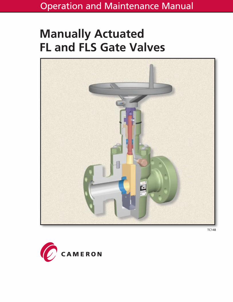
Manually ActuatedFL and FLS Gate Valves
TC148
Operation and Maintenance Manual
All the information contained in this manual is the exclusive property ofCameron. Any reproduction or use of the calculations, drawings, photo-graphs, procedures or instructions, either expressed or implied, is forbiddenwithout the written permission of Cameron or its authorized agent.
Initial Release A1April 1992
Revision B1April 1994
Revision C1June, 1997
Copyright ©1997 all rights reservedby
Cooper Cameron CorporationCameron Division
TC148 2Rev C1 6/97
PREFACE
The procedures included in this book are to be performed in conjunction withthe requirements and recommendations outlined in API Specifications. Anyrepairs to the equipment covered by this book should be done by anauthorized Cameron service representative. Cameron will not be responsiblefor loss or expense resulting from any failure of equipment or any damageto any property or injury or death to any person resulting in whole or in partfrom repairs performed by other than authorized Cameron personnel. Suchunauthorized repairs shall also serve to terminate any contractual or otherwarranty, if any, on the equipment and may also result in the equipment nolonger meeting applicable requirements.
File copies of this manual are maintained. Revisions and/or additions will bemade as deemed necessary by Cameron. The drawings in this book are notdrawn to scale, but the dimensions shown are accurate.
P.O. Box 1212Houston, Texas 77251-1212ph: 713-939-2211http://www.coopercameron.com
TC148 3Rev C1 6/97

�
CONTENTS
I. General Information . . . . . . . . . . . . . . . . . . . . . . . . . . . . . . . . . . . . . . . . . . . . . 7A. Description and Features . . . . . . . . . . . . . . . . . . . . . . . . . . . . . . . . . . . . . 7B. Operation Instructions . . . . . . . . . . . . . . . . . . . . . . . . . . . . . . . . . . . . . . . . 8C. Dimensional Data . . . . . . . . . . . . . . . . . . . . . . . . . . . . . . . . . . . . . . . . . . . 9D. Parts List . . . . . . . . . . . . . . . . . . . . . . . . . . . . . . . . . . . . . . . . . . . . . . . . . . 11
II. Periodic Maintenance . . . . . . . . . . . . . . . . . . . . . . . . . . . . . . . . . . . . . . . . . . . . 12A. Lubrication . . . . . . . . . . . . . . . . . . . . . . . . . . . . . . . . . . . . . . . . . . . . . . . . . 12B. Lubrication Charts . . . . . . . . . . . . . . . . . . . . . . . . . . . . . . . . . . . . . . . . . . . 12C. Body Cavity Lubrication. . . . . . . . . . . . . . . . . . . . . . . . . . . . . . . . . . . . . . . 13D. Thrust Bearing Lubrication . . . . . . . . . . . . . . . . . . . . . . . . . . . . . . . . . . . . 14
III. Troubleshooting . . . . . . . . . . . . . . . . . . . . . . . . . . . . . . . . . . . . . . . . . . . . . . . . 14IV. Bonnet Grease Fitting Replacement. . . . . . . . . . . . . . . . . . . . . . . . . . . . . . . . . 14
A. Valves 10,000 psi WP and Below . . . . . . . . . . . . . . . . . . . . . . . . . . . . . . . 14B. Valves 15,000 psi WP and Above . . . . . . . . . . . . . . . . . . . . . . . . . . . . . . . 16
V. Stem Shear Pin and Thrust Bearing Replacement. . . . . . . . . . . . . . . . . . . . . . 17A. Removal of the Thrust Bearings . . . . . . . . . . . . . . . . . . . . . . . . . . . . . . . . 17B. Installation of the New Thrust Bearings. . . . . . . . . . . . . . . . . . . . . . . . . . . 17
VI. Stem Packing Replacement with Pressure in the Valve. . . . . . . . . . . . . . . . . . 18A. Removal of the Stem Packing . . . . . . . . . . . . . . . . . . . . . . . . . . . . . . . . . . 18B. Installation of the New Packing . . . . . . . . . . . . . . . . . . . . . . . . . . . . . . . . . 20
VII. Gate and Seat Replacement . . . . . . . . . . . . . . . . . . . . . . . . . . . . . . . . . . . . . . 22A. Gate and Seat Disassembly . . . . . . . . . . . . . . . . . . . . . . . . . . . . . . . . . . . 22B. Gate and Seat Inspection . . . . . . . . . . . . . . . . . . . . . . . . . . . . . . . . . . . . . 22C. Gate and Seat Assembly. . . . . . . . . . . . . . . . . . . . . . . . . . . . . . . . . . . . . . 23
VIII. Ordering Replacement Parts . . . . . . . . . . . . . . . . . . . . . . . . . . . . . . . . . . . . . . 25
TC148 5Rev C1 6/97

�
I. GENERAL INFORMATION
A. Description and Features
The FL or FLS gate valve is a full-bore through-conduit valve designed andmanufactured in accordance with API 6A and NACE MR-01-75. It is availablein standard double flange, threaded-end, and special block body configurations.The following are standard features of the FL and FLS gate valves:
1. Sealing at the gate-to-seat and the seat-to-body is metal-to-metal.
2. The simplified gate and seat assembly has a minimum number of parts.One-piece seats and slab gate ensure reliable sealing and simplify fieldservice. The modified Acme gate-to-stem thread allows the gate to moveback and forth, or float, to seal against the seat.
3. The gate and seat assembly seals in both directions, and the gate and seatscan be reversed for increased life.
4. The stem shoulder can be backseated against the bonnet to isolate thestuffing box, which allows field-replacement of the stem packing while thevalve is under pressure.
5. The non-rising stem prevents a cavity pressure increase or displacementof cavity lubricant.
6. All FL and FLS valves have a specially designed, metal-to-metal sealinggrease fitting which contains a check valve. The stem, gate, and seat arelubricated through the grease fitting which is located on the downstreamside of the stem backseat for safety. No sealant or lubrication ports extenddirectly into the valve cavity.
7. The seal between the valve body and bonnet is a pressure-energized,BX-style metal bonnet gasket on 10,000 and 15,000 psi WP valves. Valvesfor 3000 and 5000 psi WP use a flat compression-type metal gasket.
8. API 6A Materials Classes and Temperature Classes are available, andother special trims are available upon request. Reduced-hardness bonnetbolting can be supplied for most sizes and pressures without downratingthe working pressure.
9. With minor modifications, FL and FLS valves can meet or exceed API 6FAfire safety requirements.
10. Special non-elastomeric stem packing designs can extend the standardtemperature rating of the FL or FLS Gate Valve up to 350° F, or down to-75° F. These temperature ratings may not be available in all workingpressures.
TC148 7Rev C1 6/97
11. An optional add-on torque multiplier is available for larger FL and FLS valvesto provide easier operation.
12. See the valve assembly bill-of materials for materials and descriptions ofvalve components.
B. Operation Instructions
A gate valve should always be in either the full-open or full-closed position.Leaving the gate partially open or throttling through the valve could causedamage to the gate.
The valve is opened by turning the handwheel counterclockwise (to the left) untilit stops. Turning the handwheel back to the right 1/4 turn will then relieve anystress in the stem,and is, therefore, recommended practice. Initial torque re-quired to open the valve is given in Table I.
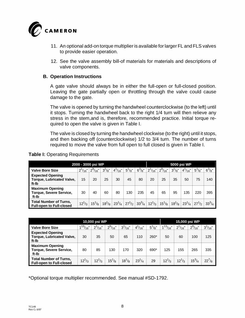
The valve is closed by turning the handwheel clockwise (to the right) until it stops,and then backing off (counterclockwise) 1/2 to 3/4 turn. The number of turnsrequired to move the valve from full open to full closed is given in Table I.
Table I: Operating Requirements
2000 - 3000 psi WP 5000 psi WP
Valve Bore Size 21/16" 29/16" 31/8" 41/16" 51/8" 63/8" 21/16" 29/16" 31/8" 41/16" 51/8" 63/8"Expected OpeningTorque, Lubricated Valve,ft-lb
15 20 25 30 45 80 20 25 35 50 75 140
Maximum OpeningTorque, Severe Service, ft-lb
30 40 60 80 130 235 45 65 95 135 220 395
Total Number of Turns,Full-open to Full-closed 121/3 151/8 181/8 231/4 271/2 333/4 121/3 151/8 181/8 231/4 271/2 333/4
10,000 psi WP 15,000 psi WP
Valve Bore Size 113/16" 21/16" 29/16" 31/16" 41/16" 51/8" 113/16" 21/16" 29/16" 31/16"Expected OpeningTorque, Lubricated Valve,ft-lb
30 35 50 65 110 260* 50 60 100 125
Maximum OpeningTorque, Severe Service, ft-lb
80 85 130 170 320 690* 125 155 265 335
Total Number of Turns,Full-open to Full-closed 121/3 121/3 151/8 181/8 231/4 29 121/3 121/3 153/4 227/8
*Optional torque multiplier recommended. See manual #SD-1792.
TC148 8Rev C1 6/97
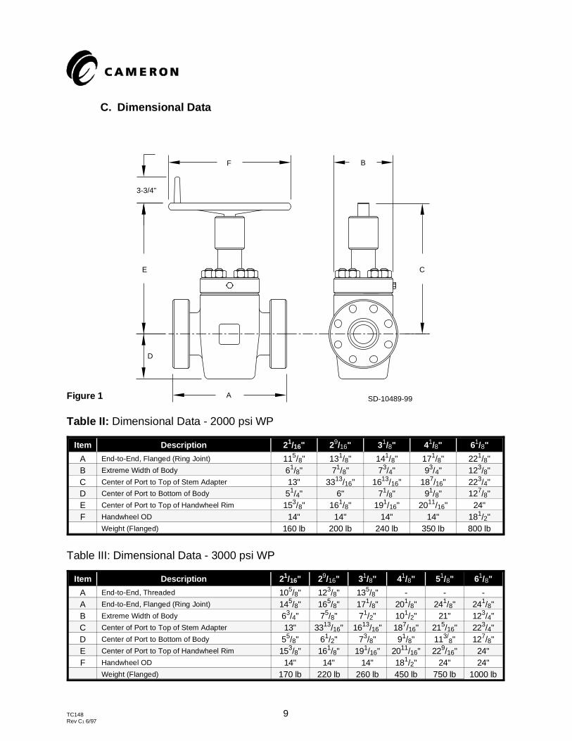
C. Dimensional Data
Table II: Dimensional Data - 2000 psi WP
Item Description 2 1/16" 29/16" 31/8" 41/8" 61/8"
A End-to-End, Flanged (Ring Joint) 115/8" 131/8" 141/8" 171/8" 221/8"B Extreme Width of Body 61/8" 71/8" 73/4" 93/4" 123/8"C Center of Port to Top of Stem Adapter 13" 3313/16" 1613/16" 187/16" 223/4"D Center of Port to Bottom of Body 51/4" 6" 71/8" 91/8" 127/8"E Center of Port to Top of Handwheel Rim 153/8" 161/8" 191/16" 2011/16" 24"F Handwheel OD 14" 14" 14" 14" 181/2"
Weight (Flanged) 160 lb 200 lb 240 lb 350 lb 800 lb
Table III: Dimensional Data - 3000 psi WP
Item Description 2 1/16" 29/16" 31/8" 41/8" 51/8" 61/8"
A End-to-End, Threaded 105/8" 123/8" 135/8" - - -A End-to-End, Flanged (Ring Joint) 145/8" 165/8" 171/8" 201/8" 241/8" 241/8"B Extreme Width of Body 63/4" 75/8" 71/2" 101/2" 21" 123/4"C Center of Port to Top of Stem Adapter 13" 3313/16" 1613/16" 187/16" 215/16" 223/4"D Center of Port to Bottom of Body 55/8" 61/2" 73/8" 91/8" 113/
8" 127/8"E Center of Port to Top of Handwheel Rim 153/8" 161/8" 191/16" 2011/16" 229/16" 24"F Handwheel OD 14" 14" 14" 181/2" 24" 24"
Weight (Flanged) 170 lb 220 lb 260 lb 450 lb 750 lb 1000 lb
SD-10489-99
3-3/4"
F
E
D
A
B
C
Figure 1
TC148 9Rev C1 6/97
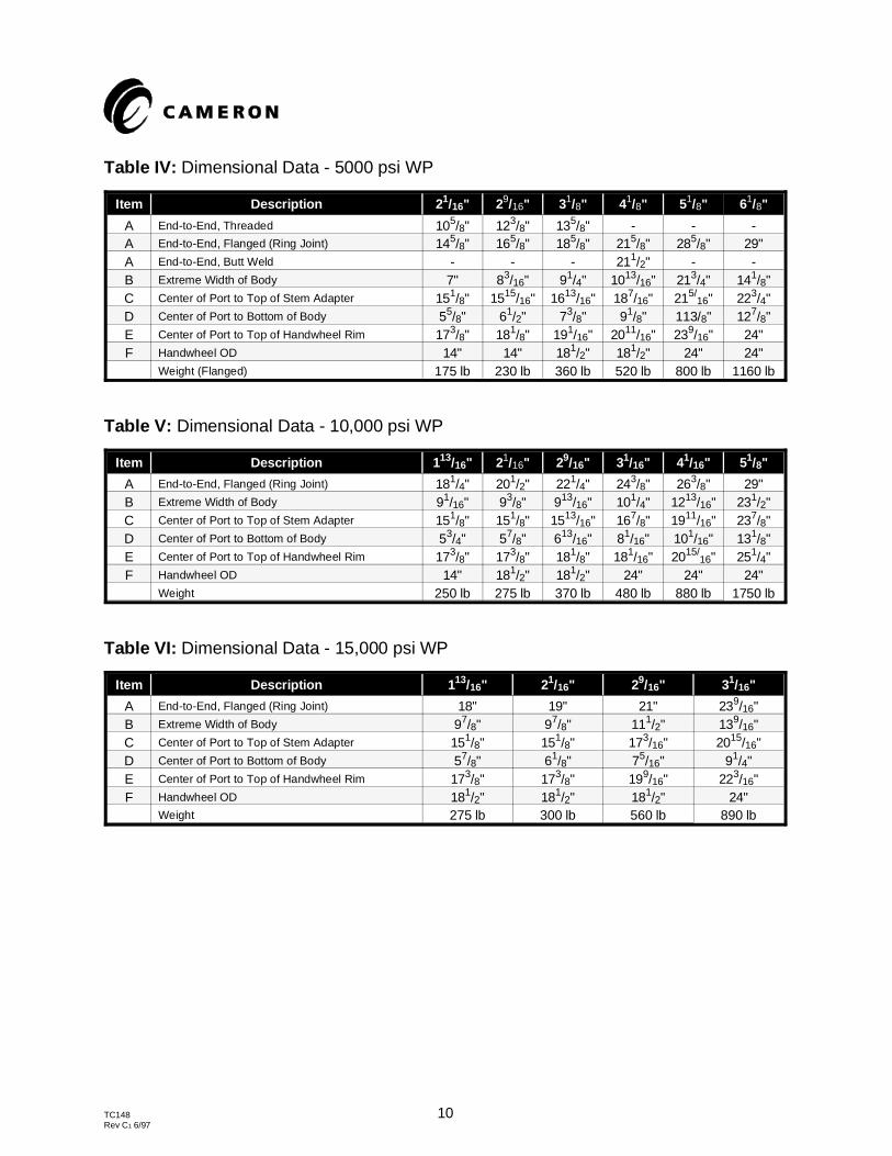
Table IV: Dimensional Data - 5000 psi WP
Item Description 2 1/16" 29/16" 31/8" 41/8" 51/8" 61/8"
A End-to-End, Threaded 105/8" 123/8" 135/8" - - -A End-to-End, Flanged (Ring Joint) 145/8" 165/8" 185/8" 215/8" 285/8" 29"A End-to-End, Butt Weld - - - 211/2" - -B Extreme Width of Body 7" 83/16" 91/4" 1013/16" 213/4" 141/8"C Center of Port to Top of Stem Adapter 151/8" 1515/16" 1613/16" 187/16" 215/
16" 223/4"D Center of Port to Bottom of Body 55/8" 61/2" 73/8" 91/8" 113/8" 127/8"E Center of Port to Top of Handwheel Rim 173/8" 181/8" 191/16" 2011/16" 239/16" 24"F Handwheel OD 14" 14" 181/2" 181/2" 24" 24"
Weight (Flanged) 175 lb 230 lb 360 lb 520 lb 800 lb 1160 lb
Table V: Dimensional Data - 10,000 psi WP
Item Description 1 13/16" 21/16" 29/16" 31/16" 41/16" 51/8"
A End-to-End, Flanged (Ring Joint) 181/4" 201/2" 221/4" 243/8" 263/8" 29"B Extreme Width of Body 91/16" 93/8" 913/16" 101/4" 1213/16" 231/2"C Center of Port to Top of Stem Adapter 151/8" 151/8" 1513/16" 167/8" 1911/16" 237/8"D Center of Port to Bottom of Body 53/4" 57/8" 613/16" 81/16" 101/16" 131/8"E Center of Port to Top of Handwheel Rim 173/8" 173/8" 181/8" 181/16" 2015/
16" 251/4"F Handwheel OD 14" 181/2" 181/2" 24" 24" 24"
Weight 250 lb 275 lb 370 lb 480 lb 880 lb 1750 lb
Table VI: Dimensional Data - 15,000 psi WP
Item Description 1 13/16" 21/16" 29/16" 31/16"
A End-to-End, Flanged (Ring Joint) 18" 19" 21" 239/16"B Extreme Width of Body 97/8" 97/8" 111/2" 139/16"C Center of Port to Top of Stem Adapter 151/8" 151/8" 173/16" 2015/16"D Center of Port to Bottom of Body 57/8" 61/8" 75/16" 91/4"E Center of Port to Top of Handwheel Rim 173/8" 173/8" 199/16" 223/16"F Handwheel OD 181/2" 181/2" 181/2" 24"
Weight 275 lb 300 lb 560 lb 890 lb
TC148 10Rev C1 6/97
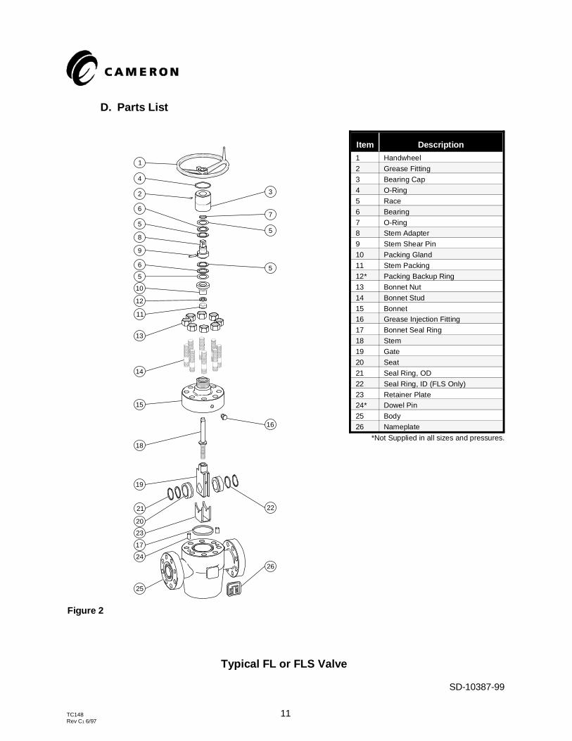
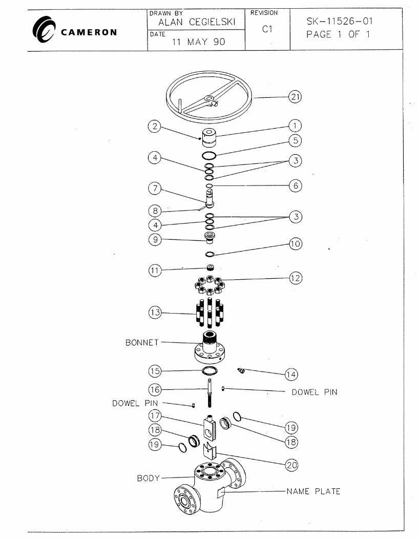
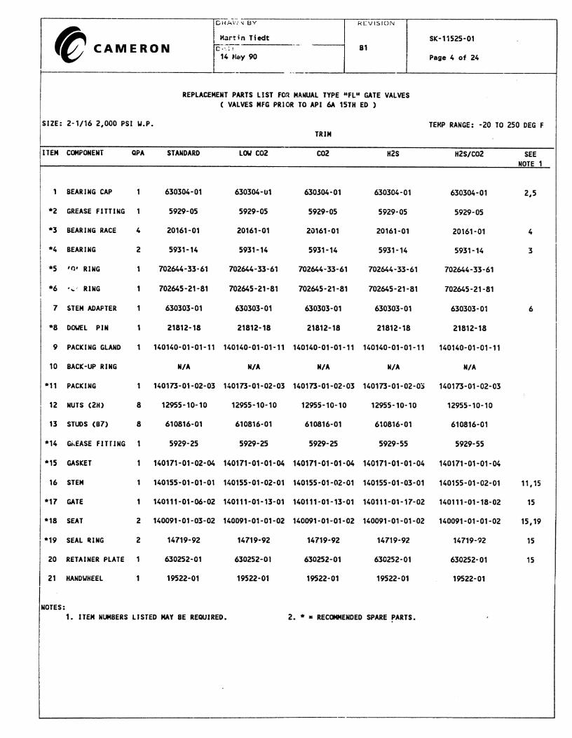
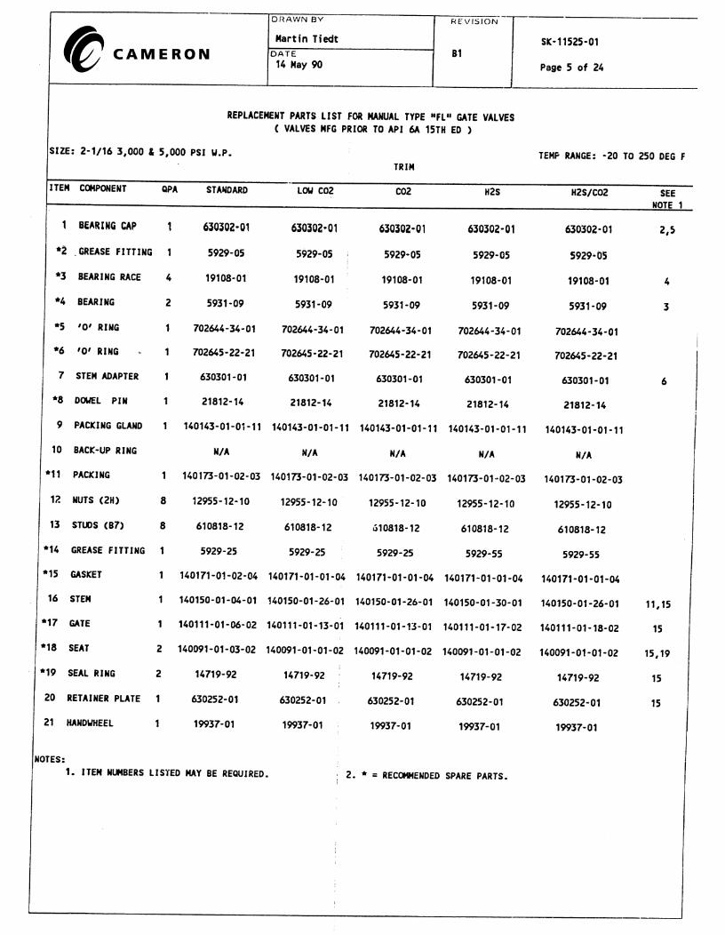
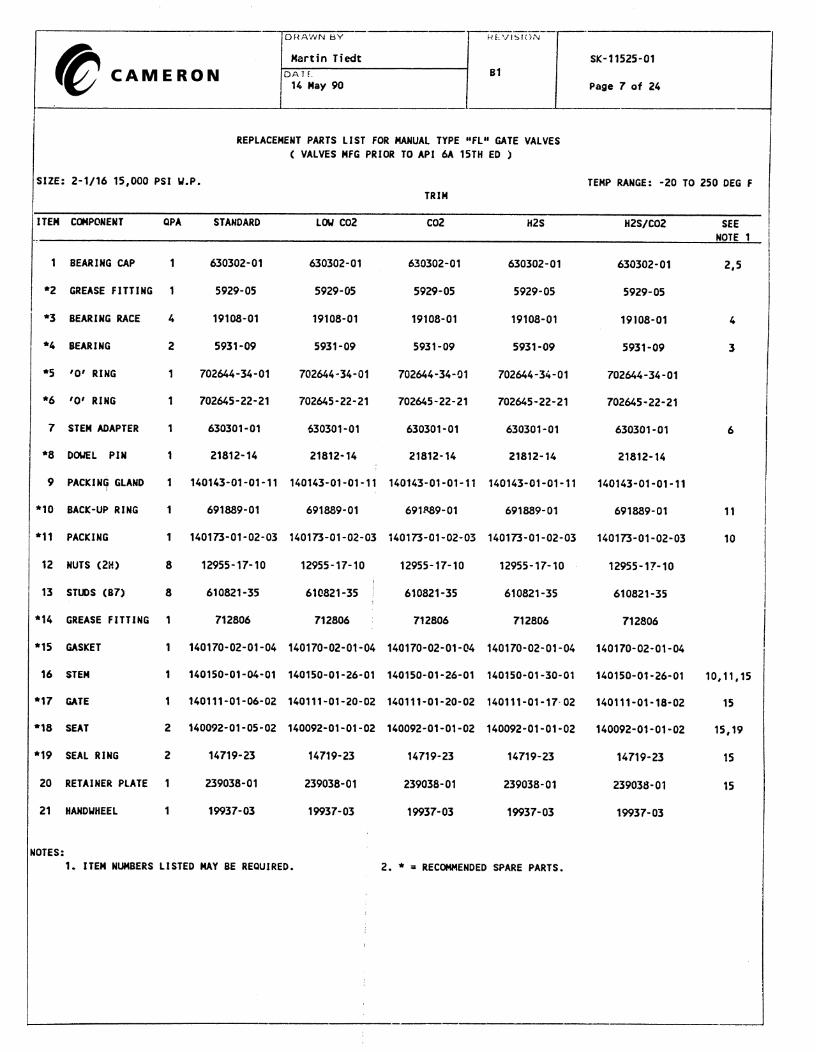
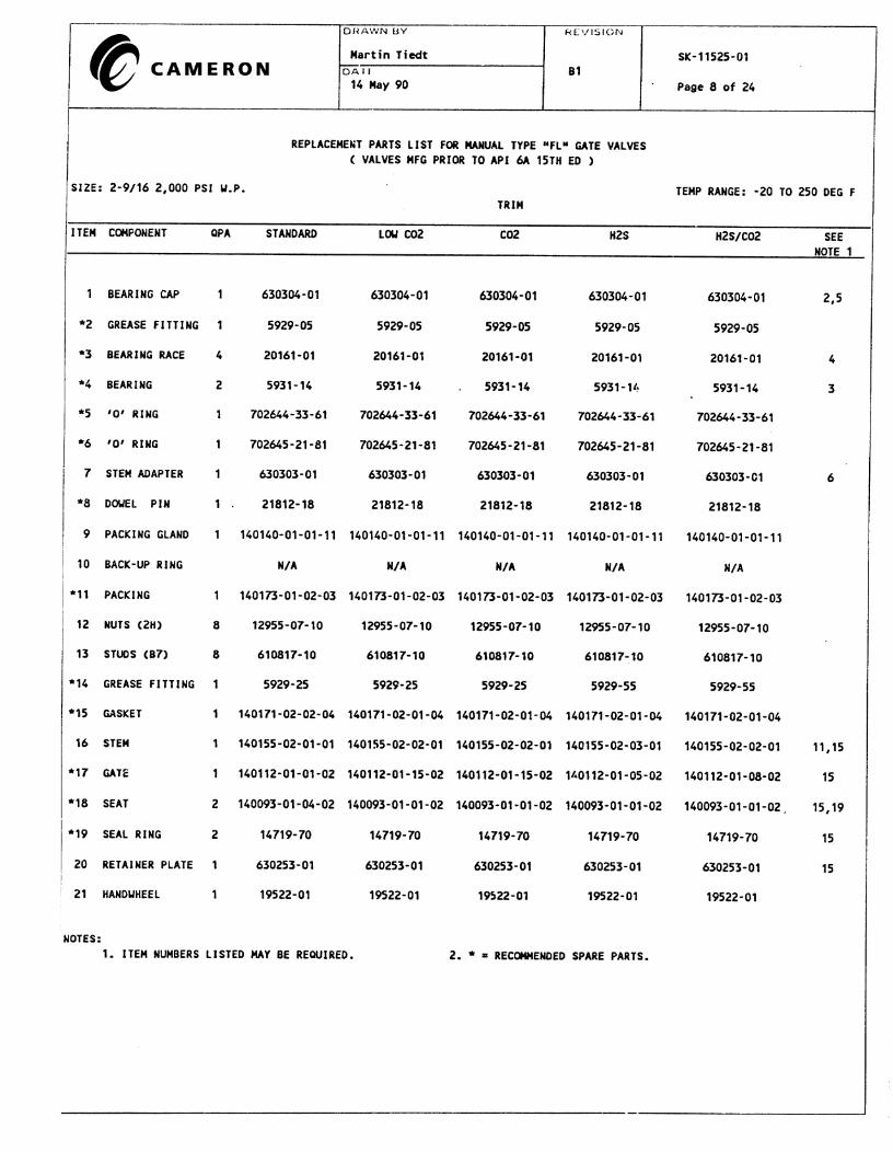
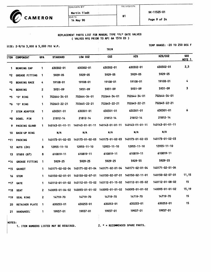
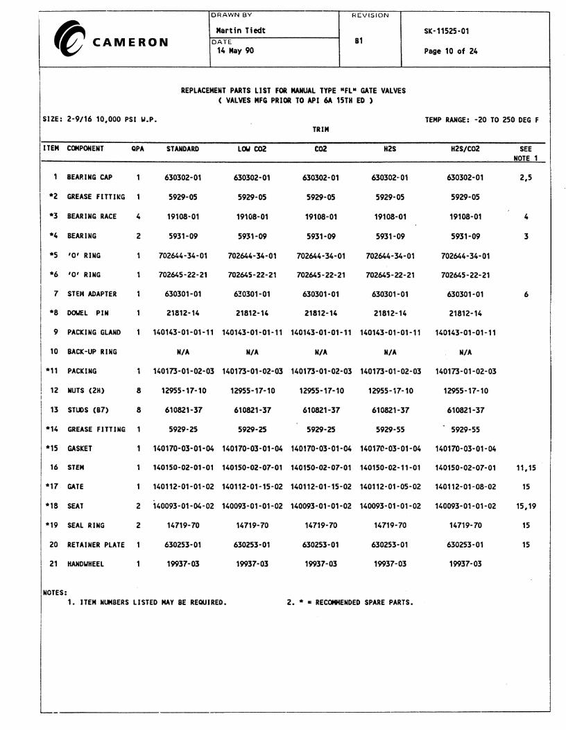
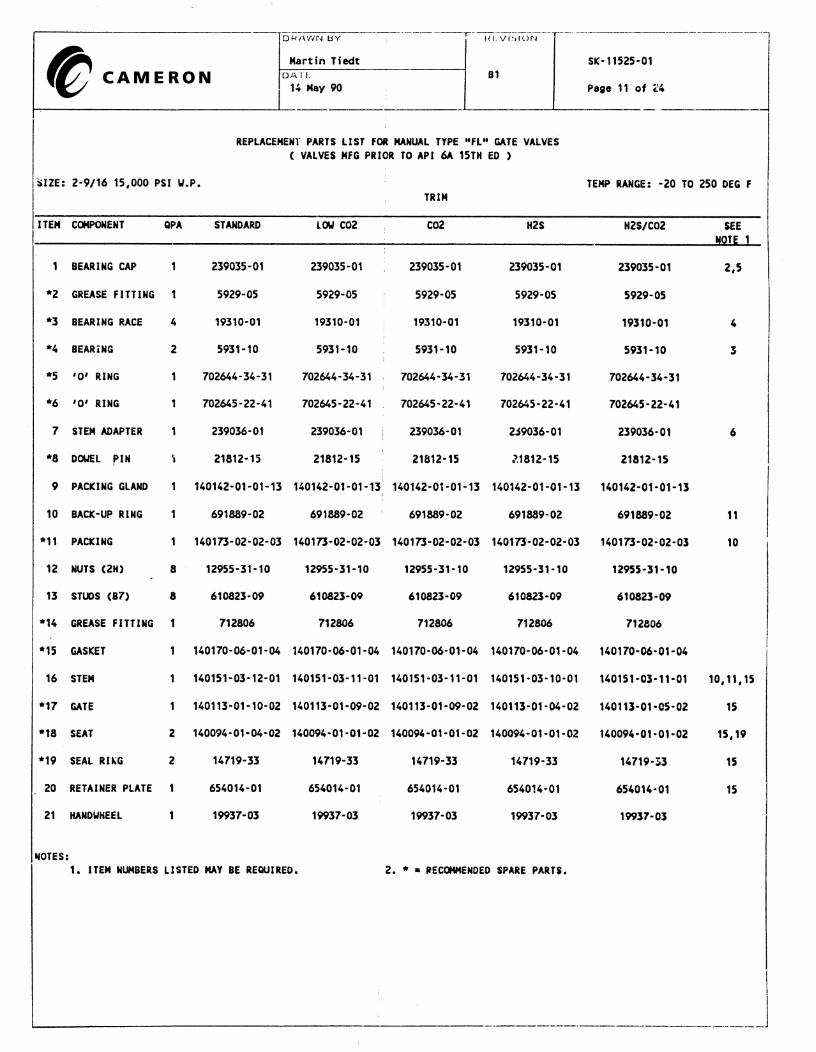
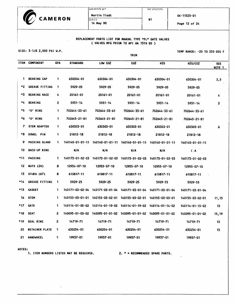
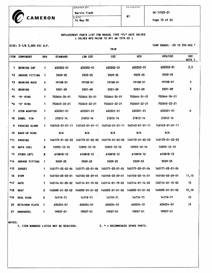
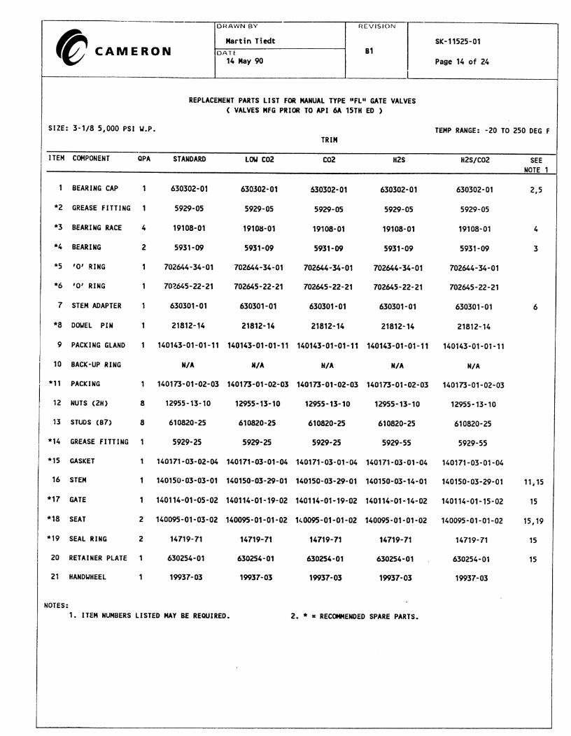
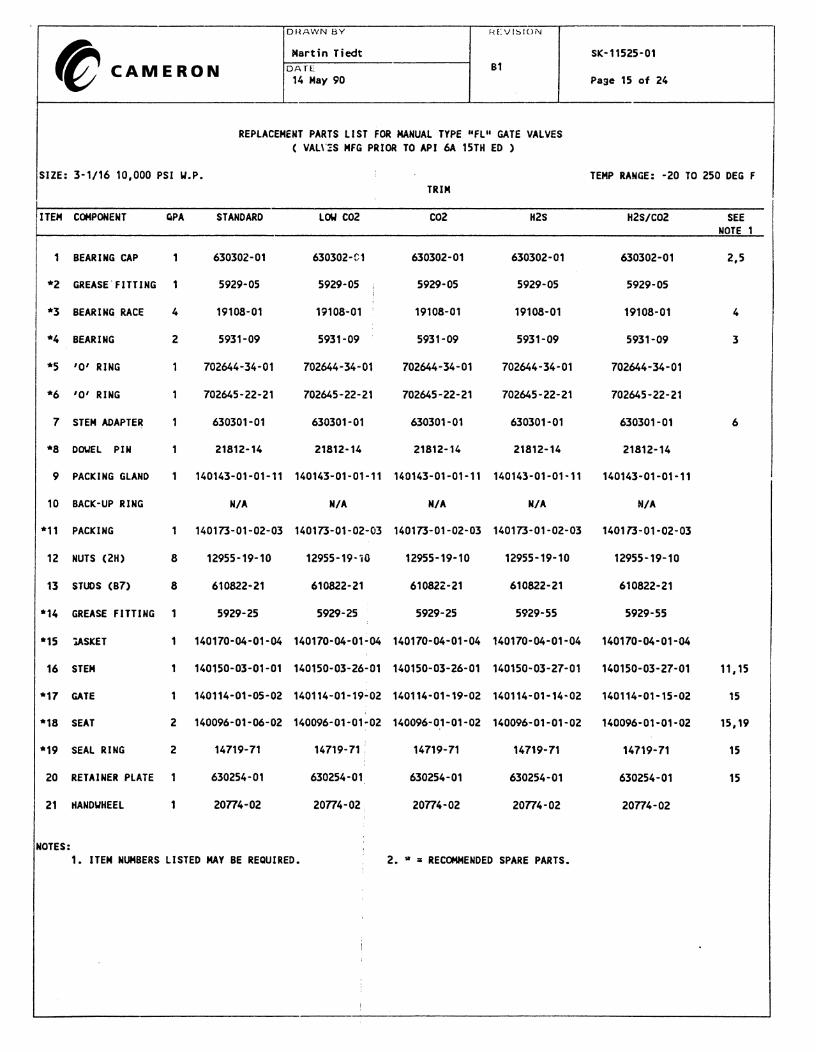
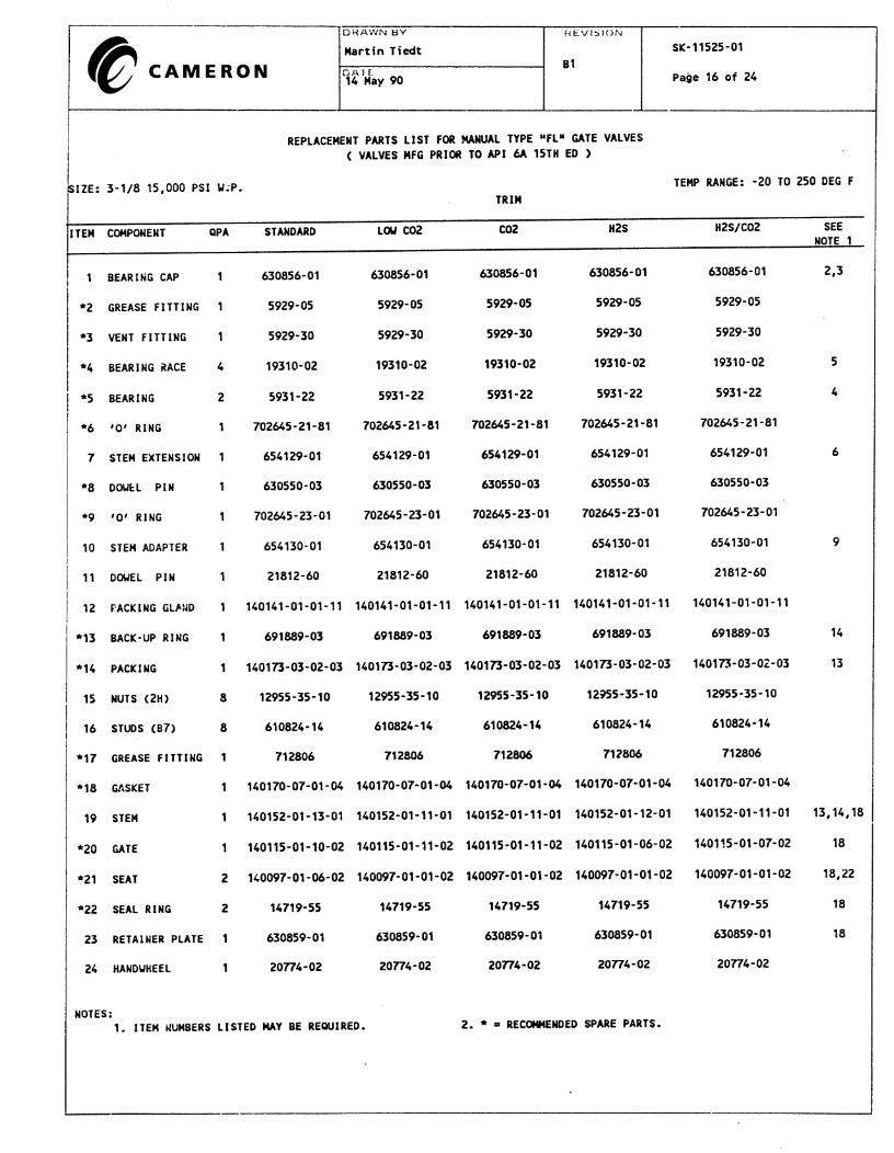
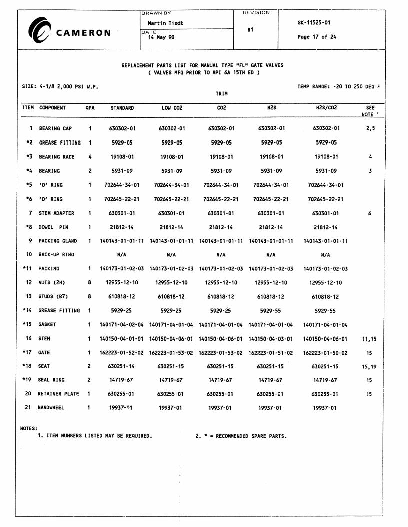
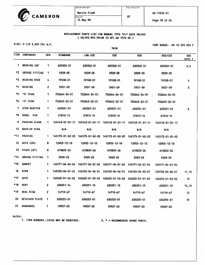
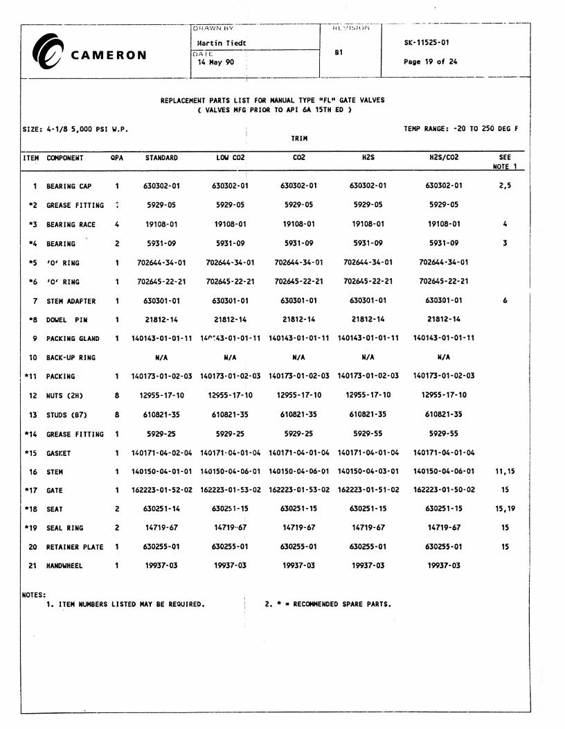
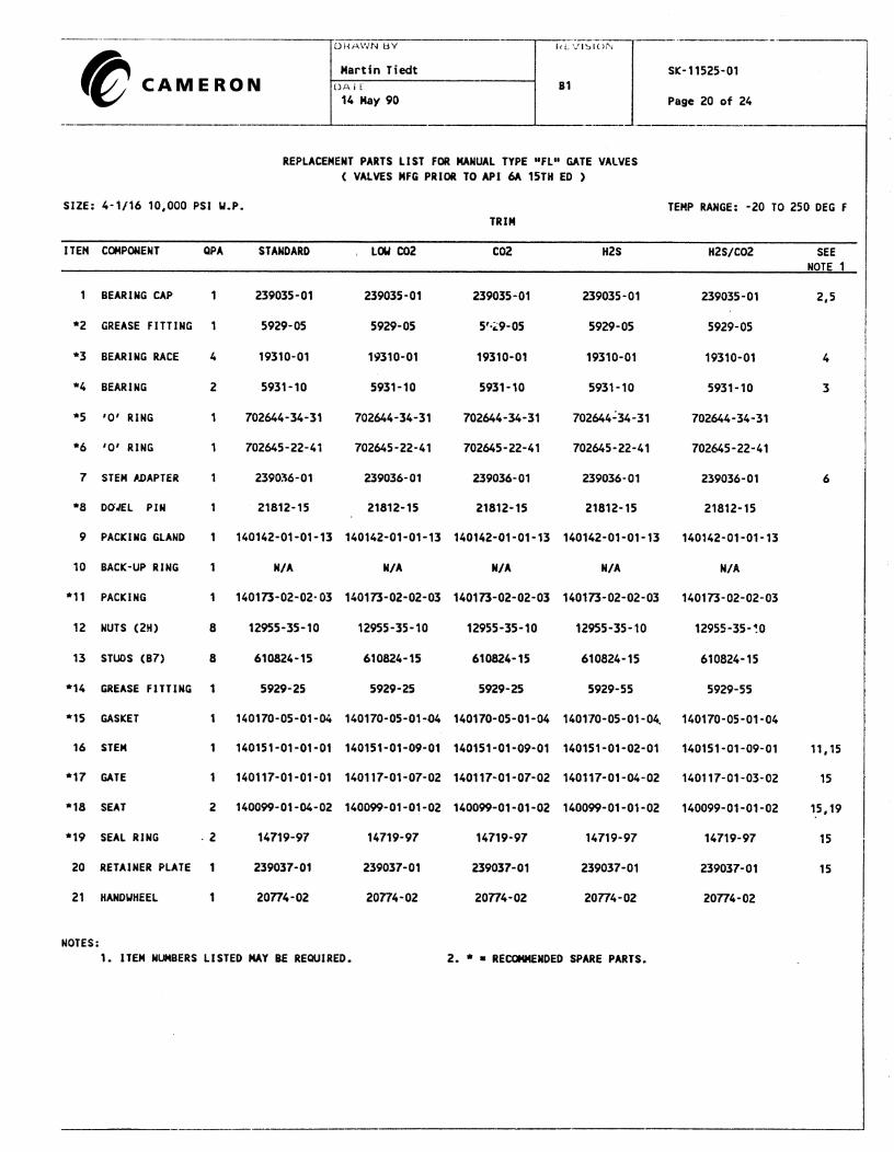
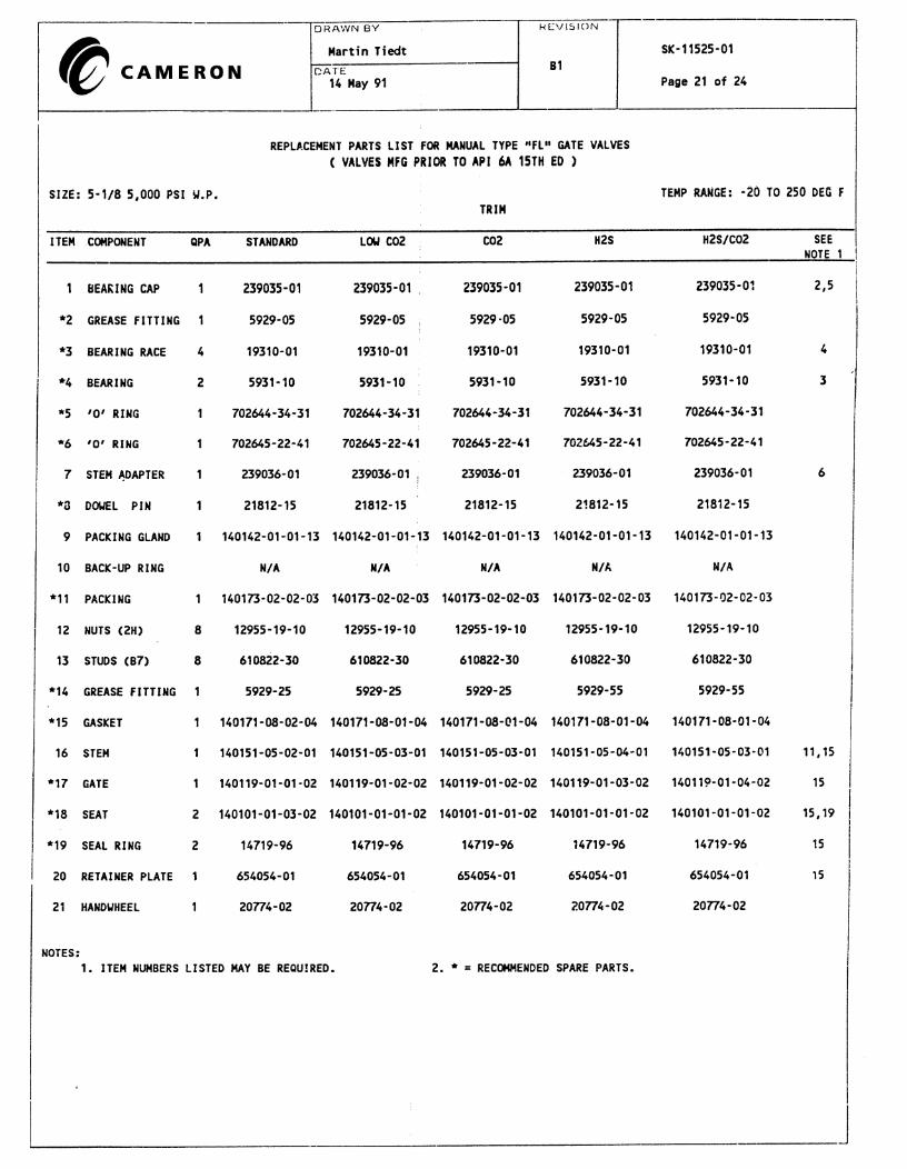
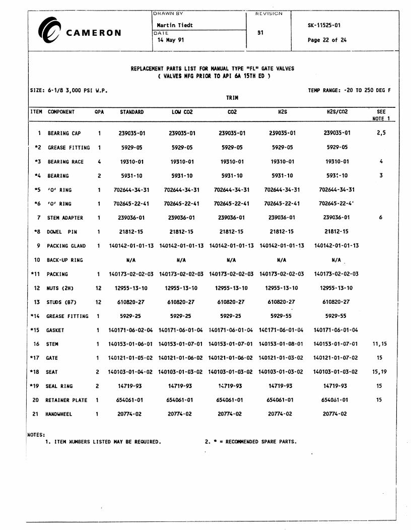
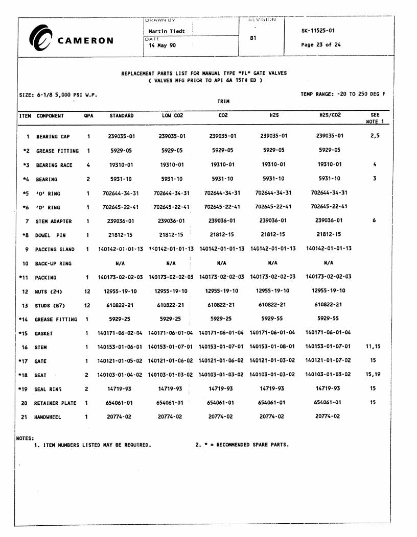
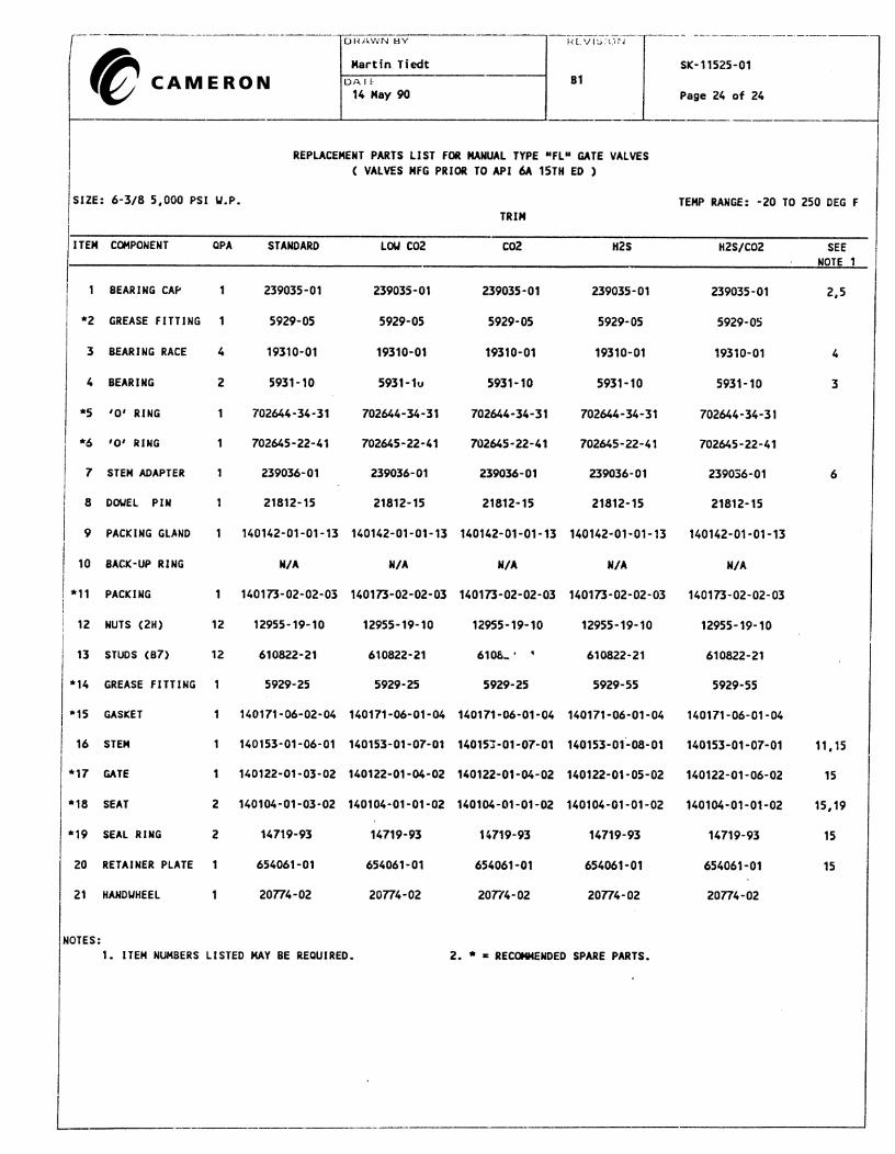
D. Parts List
Item Description
1 Handwheel
2 Grease Fitting
3 Bearing Cap
4 O-Ring
5 Race
6 Bearing
7 O-Ring8 Stem Adapter
9 Stem Shear Pin
10 Packing Gland
11 Stem Packing
12* Packing Backup Ring
13 Bonnet Nut
14 Bonnet Stud
15 Bonnet16 Grease Injection Fitting
17 Bonnet Seal Ring
18 Stem
19 Gate
20 Seat
21 Seal Ring, OD
22 Seal Ring, ID (FLS Only)
23 Retainer Plate24* Dowel Pin
25 Body
26 Nameplate
*Not Supplied in all sizes and pressures.
Typical FL or FLS Valve
SD-10387-99
Figure 2
7
3
1
4
2
6
55
8
9
6 55
10
12
11
13
14
15
16
18
19
2221
20
2624
25
23
17
TC148 11Rev C1 6/97
II. PERIODIC MAINTENANCE
A. Lubrication
1. Recommended body cavity lubricant.
a. For normal operation, use Cameron valve lubricant CI-14 or TF-41,greases not affected by water or temperatures ranging from -20° to +250°F.
b. For continuous service below 0° F, use a low temperature grease suchas “arctic grease” NS-14.
2. Recommended stem bearing lubricant
a. For normal operation, use Cameron valve lubricant CI-14 or TF-41,greases not affected by water or temperatures ranging from -20° to +250°F.
b. For continuous service below 0° F, use a low temperature grease suchas “arctic grease” NS-14.
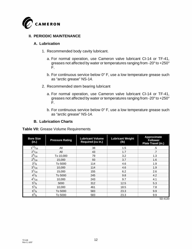
B. Lubrication Charts
Table VII: Grease Volume Requirements
Bore Size(in.) Pressure Rating Lubricant Volume
Required (cu in.)Lubricant Weight
(lb)
Approximate Follower
Plate Travel (in.)
113/16 All 38 1.5 .521/16 All 43 1.7 .729/16 To 10,000 79 3.2 1.329/16 15,000 93 3.7 1.631/8 To 5000 114 4.6 1.931/16 10,000 114 4.6 1.931/16 15,000 155 6.2 2.641/8 To 5000 245 9.8 4.241/16 10,000 243 9.7 4.151/8 5000 312 12.5 5.351/8 10,000 461 18.5 7.861/8 To 5000 583 23.3 9.963/8 To 5000 583 23.3 9.9
SD-4130
TC148 12Rev C1 6/97
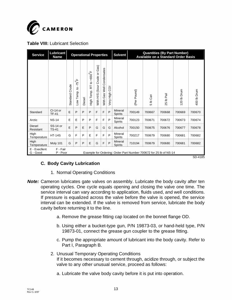
Table VIII: Lubricant Selection
Service LubricantName Operational Properties Solvent Quantities (By Part Number)
Available on a Standard Order Basis
Sta
ndar
d C
rude
Low
Tem
p. to
-75
o F
Die
sel
Hig
h T
emp.
RT
to +
650o F
With
H2 S
(S
our
Cru
de o
r G
as)
With
Gas
Wel
l Con
dens
ates
Ver
y H
igh
CO
2
(Per
Pou
nd)
5 lb
Can
25 lb
Pai
l
120
lb D
rum
400
lb D
rum
Standard CI-14 orTF-41 E P P P F F P Mineral
Spirits 700149 700667 700668 700669 700670
Arctic NS-14 E E P P F F P MineralSpirits 700123 700671 700672 700673 700674
DieselResistant
SS-14 orTS-41 E P E P G G G Alcohol 700150 700675 700676 700677 700678
HighTemperature HT-14S G F P E F F P Mineral
Spirits 700217 700679 700680 700681 700682
HighTemperature Moly 101 G P P E G F P Mineral
Spirits 710194 700679 700680 700681 700682
E - Execllent F - FairG - Good P - Poor Example for Ordering: Order Part Number 700672 for 25 lb of NS-14
SD-4185
C. Body Cavity Lubrication
1. Normal Operating Conditions
Note: Cameron lubricates gate valves on assembly. Lubricate the body cavity after tenoperating cycles. One cycle equals opening and closing the valve one time. Theservice interval can vary according to application, fluids used, and well conditions.If pressure is equalized across the valve before the valve is opened, the serviceinterval can be extended. If the valve is removed from service, lubricate the bodycavity before returning it to the line.
a. Remove the grease fitting cap located on the bonnet flange OD.
b. Using either a bucket-type gun, P/N 19873-03, or hand-held type, P/N19873-01, connect the grease gun coupler to the grease fitting.
c. Pump the appropriate amount of lubricant into the body cavity. Refer toPart I, Paragraph B.
2. Unusual Temporary Operating Conditions If it becomes necessary to cement through, acidize through, or subject thevalve to any other unusual service, proceed as follows:
a. Lubricate the valve body cavity before it is put into operation.
TC148 13Rev C1 6/97
b. Flush the valve with the appropriate neutralizing fluid in the line.
c. Operate the valve with fresh water or appropriate neutralizing fluid in theline.
d. Lubricate the valve body cavity.
D. Thrust Bearing Lubrication
Note: Lubricate the thrust bearings as often as required to ensure smooth valve operation.
1. Using a hand-held grease gun, P/N 19873-01, connect the grease gun fittingto the hydraulic grease fittings with a hydraulic coupler.
2. Pump lubricant into the fittings until clean grease appears at the bleed porton the opposite side of the bearing cap.
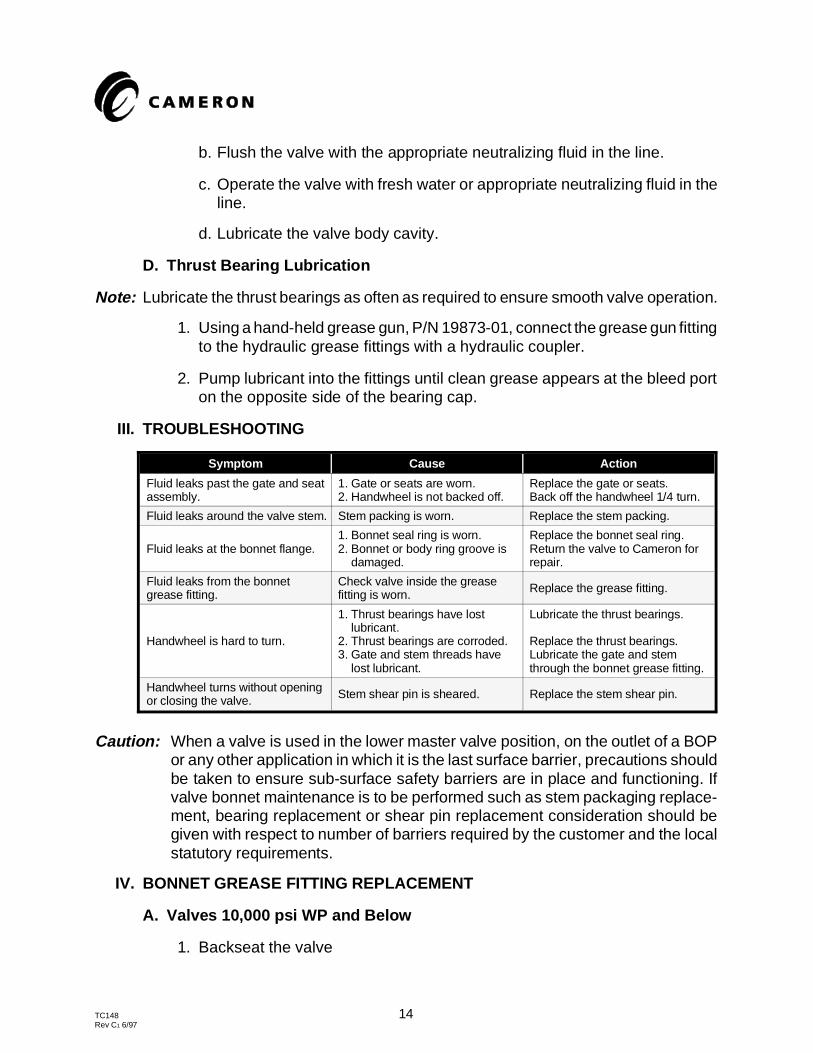
III. TROUBLESHOOTING
Symptom Cause Action
Fluid leaks past the gate and seatassembly.
1. Gate or seats are worn.2. Handwheel is not backed off.
Replace the gate or seats.Back off the handwheel 1/4 turn.
Fluid leaks around the valve stem. Stem packing is worn. Replace the stem packing.
Fluid leaks at the bonnet flange.1. Bonnet seal ring is worn.2. Bonnet or body ring groove is damaged.
Replace the bonnet seal ring.Return the valve to Cameron forrepair.
Fluid leaks from the bonnetgrease fitting.
Check valve inside the greasefitting is worn. Replace the grease fitting.
Handwheel is hard to turn.
1. Thrust bearings have lost lubricant.2. Thrust bearings are corroded.3. Gate and stem threads have lost lubricant.
Lubricate the thrust bearings.
Replace the thrust bearings.Lubricate the gate and stemthrough the bonnet grease fitting.
Handwheel turns without openingor closing the valve. Stem shear pin is sheared. Replace the stem shear pin.
Caution: When a valve is used in the lower master valve position, on the outlet of a BOPor any other application in which it is the last surface barrier, precautions shouldbe taken to ensure sub-surface safety barriers are in place and functioning. Ifvalve bonnet maintenance is to be performed such as stem packaging replace-ment, bearing replacement or shear pin replacement consideration should begiven with respect to number of barriers required by the customer and the localstatutory requirements.
IV. BONNET GREASE FITTING REPLACEMENT
A. Valves 10,000 psi WP and Below
1. Backseat the valve
TC148 14Rev C1 6/97
a. Close the valve fully.
b. Loosen the bearing cap four complete turns.
c. Turn the handwheel clockwise (the closing direction) until the gate firmlycontacts the bottom of the cavity and the stem moves outward, contactingthe internal backseat shoulder.
d. Bump the handwheel in the closing direction.
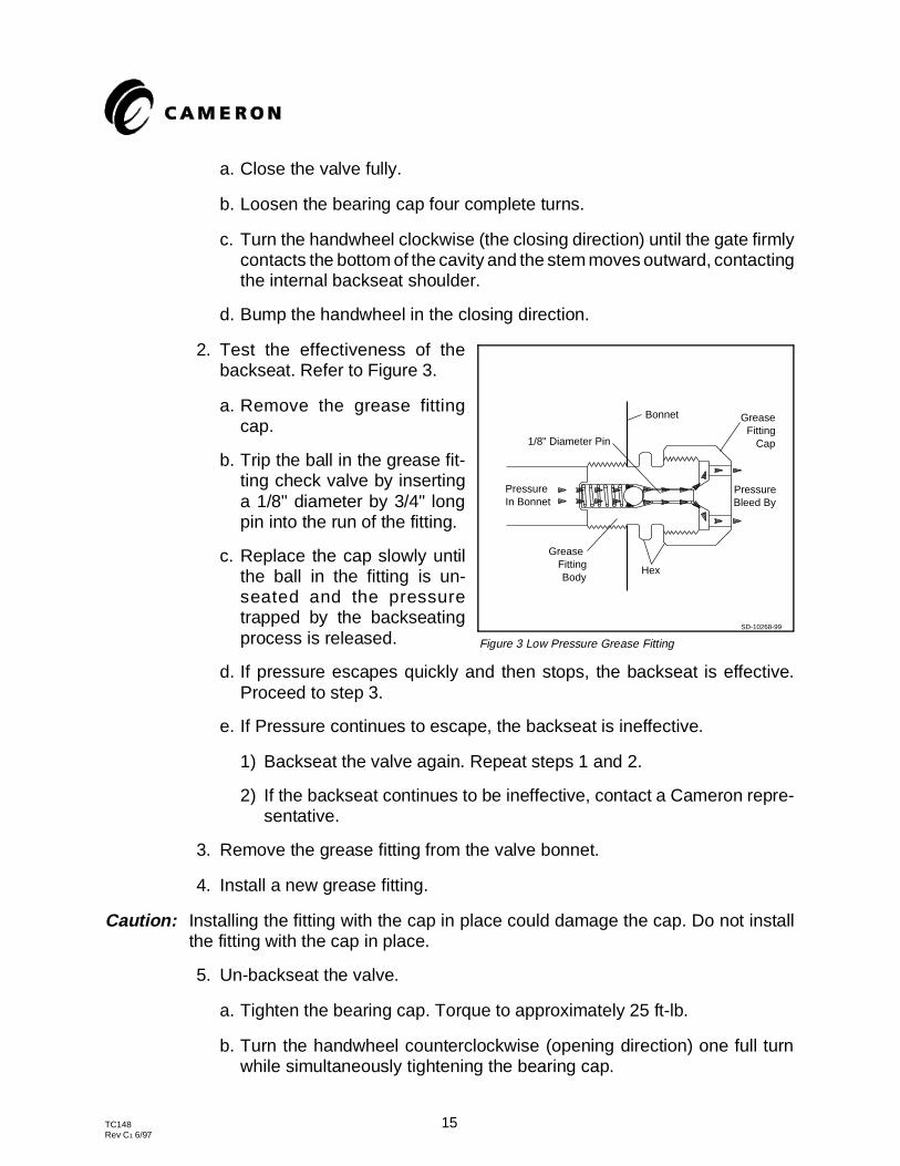
2. Test the effectiveness of thebackseat. Refer to Figure 3.
a. Remove the grease fittingcap.
b. Trip the ball in the grease fit-ting check valve by insertinga 1/8" diameter by 3/4" longpin into the run of the fitting.
c. Replace the cap slowly untilthe ball in the fitting is un-seated and the pressuretrapped by the backseatingprocess is released.
d. If pressure escapes quickly and then stops, the backseat is effective.Proceed to step 3.
e. If Pressure continues to escape, the backseat is ineffective.
1) Backseat the valve again. Repeat steps 1 and 2.
2) If the backseat continues to be ineffective, contact a Cameron repre-sentative.
3. Remove the grease fitting from the valve bonnet.
4. Install a new grease fitting.
Caution: Installing the fitting with the cap in place could damage the cap. Do not installthe fitting with the cap in place.
5. Un-backseat the valve.
a. Tighten the bearing cap. Torque to approximately 25 ft-lb.
b. Turn the handwheel counterclockwise (opening direction) one full turnwhile simultaneously tightening the bearing cap.
Figure 3 Low Pressure Grease Fitting
In BonnetPressure
BodyFitting
Grease
Bleed ByPressure
CapFitting
Grease
1/8" Diameter Pin
Bonnet
SD-10268-99
Hex
TC148 15Rev C1 6/97
c. Tighten the bearing cap to approximately 200 ft-lb.
B. Valves 15,000 psi WP and Above
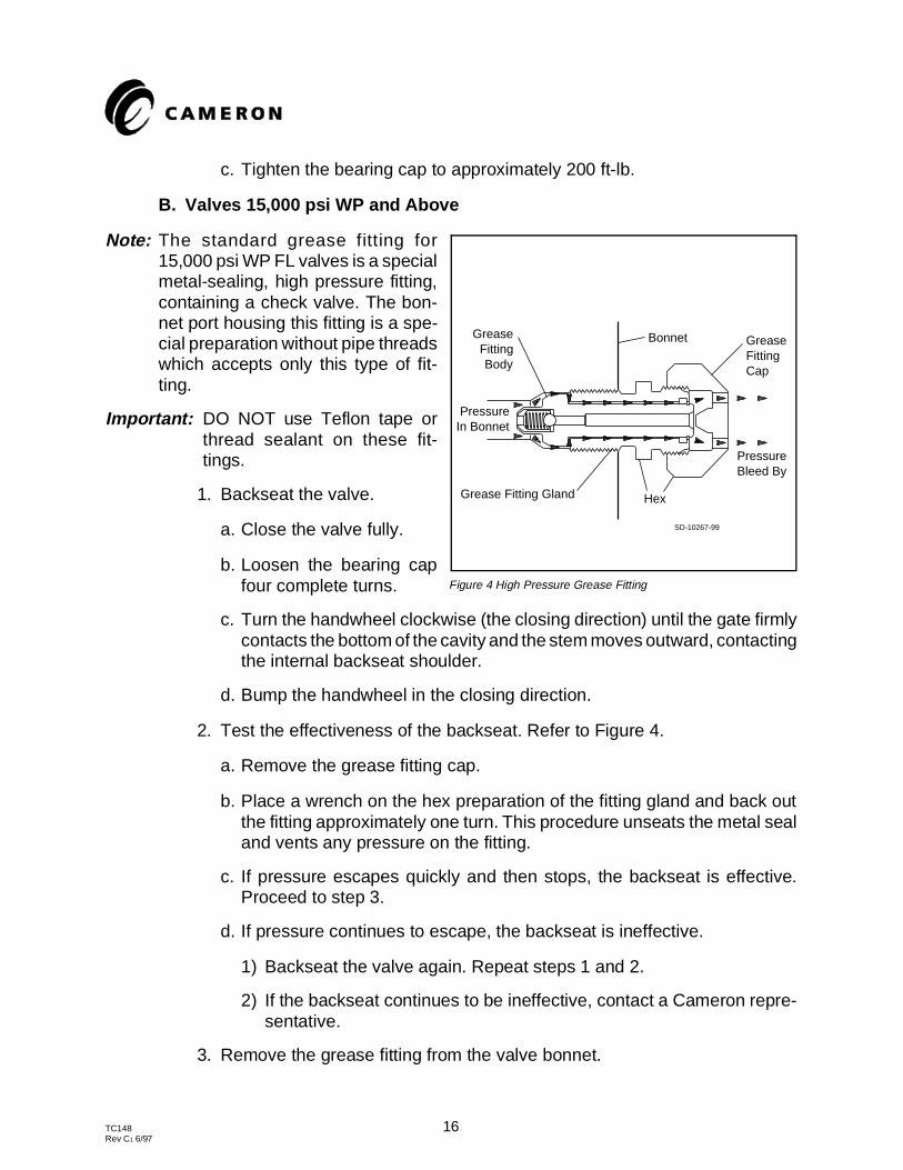
Note: The standard grease fitting for15,000 psi WP FL valves is a specialmetal-sealing, high pressure fitting,containing a check valve. The bon-net port housing this fitting is a spe-cial preparation without pipe threadswhich accepts only this type of fit-ting.
Important: DO NOT use Teflon tape orthread sealant on these fit-tings.
1. Backseat the valve.
a. Close the valve fully.
b. Loosen the bearing capfour complete turns.
c. Turn the handwheel clockwise (the closing direction) until the gate firmlycontacts the bottom of the cavity and the stem moves outward, contactingthe internal backseat shoulder.
d. Bump the handwheel in the closing direction.
2. Test the effectiveness of the backseat. Refer to Figure 4.
a. Remove the grease fitting cap.
b. Place a wrench on the hex preparation of the fitting gland and back outthe fitting approximately one turn. This procedure unseats the metal sealand vents any pressure on the fitting.
c. If pressure escapes quickly and then stops, the backseat is effective.Proceed to step 3.
d. If pressure continues to escape, the backseat is ineffective.
1) Backseat the valve again. Repeat steps 1 and 2.
2) If the backseat continues to be ineffective, contact a Cameron repre-sentative.
3. Remove the grease fitting from the valve bonnet.
Figure 4 High Pressure Grease Fitting
In BonnetPressure
BodyFitting
Grease
Grease Fitting Gland
Bleed ByPressure
Hex
Bonnet
CapFittingGrease
SD-10267-99
TC148 16Rev C1 6/97
4. Remove the cap from a new grease fitting and install the fitting in the bonnet.Torque to 80 to 100 ft-lb.
5. Install and tighten the cap on the fitting.
Caution: Installing the fitting with the cap in place prevents the fitting from seating andcould cause damage to the cap. Do not install the fitting with the cap in place.
6. Un-backseat the valve.
a. Tighten the bearing cap. Torque to approximately 25 ft-lb.
b. Turn the handwheel counterclockwise (opening direction) one full turnwhile simultaneously tightening the bearing cap.
c. Tighten the bearing cap to approximately 200 ft-lb.
V. STEM SHEAR PIN AND THRUST BEARING REPLACEMENT
Note: The stem thrust bearings can be replaced while the valve is under pressure in theline.
A. Removal of the Thrust Bearings
1. Loosen the bearing cap, using a 24" pipe wrench. After two or three turns,the cap will rotate freely by hand.
Caution: If the cap does not rotate freely after three turns, the packing gland may bemoving outward with the bearing cap. This can be checked by tapping on thestem adaptor so it moves relative to the bearing cap. If the stem adaptor doesnot move inward or continues to back out with the bearing cap, DO NOT removethe cap. Tighten the cap and contact a Cameron representative.
2. If the bearing cap rotates freely, remove the cap from the bonnet.
3. Using a punch, drive the stem shear pin from the stem adapter, ensuringthat the adapter is not damaged.
4. Remove the adapter from the stem.
5. Remove both sets of bearings and bearing races from the stem adapter.
6. Discard any pitted, cracked, or damaged bearings or races.
7. Replace the stem adapter if either of the bearing surfaces on the adaptershoulder is damaged.
B. Installation of the New Thrust Bearings
1. Remove the new bearings from the protective packaging.
TC148 17Rev C1 6/97
2. Pack the bearings with clean grease.
3. Place each bearing between a pair of carefully cleaned races.
4. Carefully clean the stem adapter.
5. Install one set of bearings and races over the bottom of the adapter andone set over the top of the adapter.
Note: The adapter O-ring may be removed temporarily to allow for the installation of thetop bearing and race assembly.
6. Insert the stem adapter over the end of the stem and align the pin hole inthe adapter with the hole in the stem.
7. Using a punch, drive in the stem pin and ensure that the pin does notprotrude over the OD of the adapter shoulder.
Caution: Do not strike the bearings, races, or stem adapter with the punch or hammer.
8. Replace the stem adapter O-ring if necessary.
9. Inspect the bearing cap to ensure that an extra race, held by grease tension,is not retained inside.
10. Clean the bearing cap and lubricate the threads.
11. Install the cap, and tighten to approximately 200 ft-lb.
12. Rotate the stem adapter counterclockwise to ensure that the gate is off thebottom of the body. This procedure will confirm that the stem backseatingshoulder is not contacting the bonnet shoulder.
13. Inject grease through the bearing cap grease fittings until the excess greasepasses through the bleed port.
VI. STEM PACKING REPLACEMENT WITH PRESSURE IN THE VALVE
A. Removal of the Stem Packing
Note: If there is no pressure in the valve, proceed to step 3.
1. Backseat the valve.
a. Close the valve fully.
b. Loosen the bearing cap four complete turns.
TC148 18Rev C1 6/97
c. Turn the handwheel clockwise (the closing direction) until the gate firmlycontacts the bottom of the cavity and the stem moves outward, contactingthe internal backseat shoulder.
d. Bump the handwheel in the closing direction.
2. Test the effectiveness of the backseat.
a. Valves 10,000 psi WP and Below. Refer to Figure 3.
1) Remove the bonnet grease fitting cap.
2) Trip the ball in the grease fitting check valve by inserting an 1/8“diameter by 3/4” long pin into the run of the fitting.
3) Replace the cap slowly until the ball in the fitting is unseated and thepressure trapped by the backseating process is released.
4) If pressure escapes quickly and then stops, the backseat is effective.Proceed to step 3.
5) If pressure continues to escape, the backseat is ineffective.
a) Backseat the valve again. Repeat steps 1 and 2.
b) If the backseat continues to be ineffective, contact a Cameronrepresentative.
b. Valves 15,000 psi WP and Above. Refer to Figure 4.
1) Remove the grease fitting cap.
2) Place a wrench on the hex preparation of the fitting gland and backout the fitting approximately one turn. This procedure unseats themetal seal and vents any pressure on the fitting.
3) If pressure escapes quickly and then stops, the backseat is effective.Proceed to step 3.
4) If pressure continues to escape, the backseat is ineffective.
a) Backseat the valve again. Repeat steps 1 and 2.
b) If the backseat continues to be ineffective, contact a Cameronrepresentative.
3. Remove the handwheel and bearing cap.
4. Remove the cap from the bonnet.
TC148 19Rev C1 6/97
5. Using a punch, drive the stem shear pin from the stem adapter, ensuringthat the adapter is not damaged.
6. Remove the adapter from the stem.
7. Remove both sets of bearings and bearing races from the stem adapter.
8. Loosen the packing gland.
9. Ensure that the threads on the bonnet neck OD are not damaged.
10. Remove the packing gland.
11. Remove the stem packing and backup ring (if applicable).
a.Use packing sleeve P/N 21168 for 1" stem size and packing sleeve P/N233842 for 11/4" stem size.
1) Thread the packing sleeve into the bonnet packing gland preparationuntil the sleeve bottoms out.
2) Using a grease gun attached to the bonnet grease fitting, pump thepacking out into the recessed area of the packing sleeve.
3) Remove the sleeve from the bonnet.
b. If a packing sleeve is not available, remove the stem packing by one ofthe following methods:
1) Pump the packing out with grease until the grease bypasses or thepacking refuses to extrude further.
2) Pull the packing out with a corkscrew.
Caution: Do not damage the stem or packing bore.
B. Installation of the New Packing
1. Clean the grease from the stuffing box bore so that a hydraulic lock will notprevent the installation of new packing.
2. Inspect the stuffing box to ensure that the bore is clean and free of pits orscars.
3. Inspect the stem to ensure that the surface is free of burrs and pits.
4. Apply a light coat of grease to:
a. The stem
b. The stuffing box bore
TC148 20Rev C1 6/97
c. The ID and OD of the stem packing
d. The nose and threads of the packing gland.
5. Lightly grease the new stem packing. Install it over the stem and into thebonnet as follows:
a. J packing or U packing: Install with rounded nose facing pressure.
b. Varipak packing: Install with open end facing pressure.
c. HT-20 packing: Call Cameron service. (Special tools required; not userreplaceable).
6. Using the packing gland as a pushing tool, push the packing into the stuffingbox.
7. Remove the packing gland and lubricate the stem OD. If a packing back-upring is required, install it over the stem.
8. Install the packing gland and apply approximately 200 ft-lb of torque,ensuring that the bonnet threads are not damaged.
9. Inspect the bearings and bearing races on the stem adapter for pits, scores,or cracks. Replace if damaged.
10. Pack the bearings with grease.
11. Place each bearing between a pair of carefully cleaned races.
12. Carefully clean the stem adapter.
13. Install one set of bearings and races over the bottom of the adapter andone set over the top of the adapter.
Note: The adapter O-ring may be removed temporarily to allow for the installation of thetop bearing and race assembly.
14. Insert the stem adapter over the end of the stem and align the pin hole inthe adapter with the hole in the stem.
15. Using a punch, drive in the stem pin and ensure that the pin does notprotrude over the OD of the adapter shoulder.
Caution: Do not strike the bearings, races, or stem adapter with the punch or hammer.
16. Replace the stem adapter O-ring if necessary.
17. Inspect the bearing cap to ensure that an extra race, held by grease tension,is not retained inside.
TC148 21Rev C1 6/97
18. Clean the bearing cap and lubricate the threads.
19. Install the cap, and torque to 200 ft-lb.
20. Rotate the stem adapter counterclockwise to ensure that the gate is off thebottom of the body. This procedure will confirm that the stem backseatingshoulder is not contacting the bonnet shoulder.
21. Inject grease through the bearing cap grease fitting until the excess greasepasses through the bleed port.
22. Lubricate the body cavity. Refer to Part I.
VII. GATE AND SEAT REPLACEMENT
A. Gate and Seat Disassembly
1. Isolate the valve from the line pressure.
2. Release the cavity pressure by bleeding the bonnet grease fitting.
3. Fully open the valve to ensure that the stem is completely within the gateneck.
4. Remove the bonnet nuts.
5. Support the bonnet and turn the handwheel clockwise until the stemcompletely backs out of the gate.
6. Remove the bonnet assembly.
7. Pull the gate from the body.
8. Remove the seats.
Note: If the seats are stuck, insert a screwdriver in the groove on the OD of the seats andpry out the seats.
9. Remove the retainer plate from the bottom of the body cavity.
10. Flush the body cavity thoroughly with a suitable solvent and wipe clean witha rag.
B. Gate and Seat Inspection
1. Inspect the cavity parts for damage.
a. Ensure that the retainer plate is not bent, twisted, or distorted.
Important: Solid material should not be built up on the retainer plate surfaces.
TC148 22Rev C1 6/97
b. Ensure that the seal rings are not damaged.
c. Ensure that the seats are not cut or damaged.
d. Ensure that the gate is not cut or damaged.
2. Replace any damaged parts.
3. Ensure that the body cavity is free of all foreign matter such as solidparticles, grit, trash, etc.
4. Clean the body cavity with a suitable cleaning solvent.
5. Apply a thin coat of clean grease to the body cavity, gate, retainer plate,seats, and seat seal rings.
6. Install the U-shaped retainer plate in the bottom of the body cavity. The flatcenter part of the retainer plate goes against the cavity bottom, and thesemi-circular cut-outs must be aligned with the seat pockets.
C. Gate and Seat Assembly
1. Install the seal rings into the face groove(s) located in the seats.
Note: The FL valve uses one seal ring per seat; the FLS uses two per seat.
2. Install the seats into the seat pockets.
Note: The grooved seat face with its seal ring(s) goes against the body seat pocket sealface. Do not apply more than a very thin film of grease to the back face of the seatand seal ring(s) or the seal face on the body seat pocket.
3. Install the gate into the cavity between the seats.
4. Push the gate all the way to the bottom of the cavity and pack the remainingspace with grease.
5. Remove the seal ring from the bonnet groove.
6. Clean the grooves and/or seating area of the body and bonnet.
7. Apply a very thin film of clean grease to the bonnet seal ring and groove.
8. Install the new seal ring in the bonnet groove.
9. Install the bonnet over the body studs.
a. On valves 5000 psi WP and below, rotate the bonnet so that the bonnetlocating pins in the body align with the pin holes in the bonnet.
TC148 23Rev C1 6/97
b. On valves 10,000 psi WP and above, rotate the bonnet until the greasefitting is 90° from the gate bore.
10. Thread the stem into the gate by turning the handwheel counterclockwise.
11. Pull the bonnet down over the studs.
12. Hand tighten the bonnet nuts.
13. Ensure that the gate is not on the bottom of the cavity.
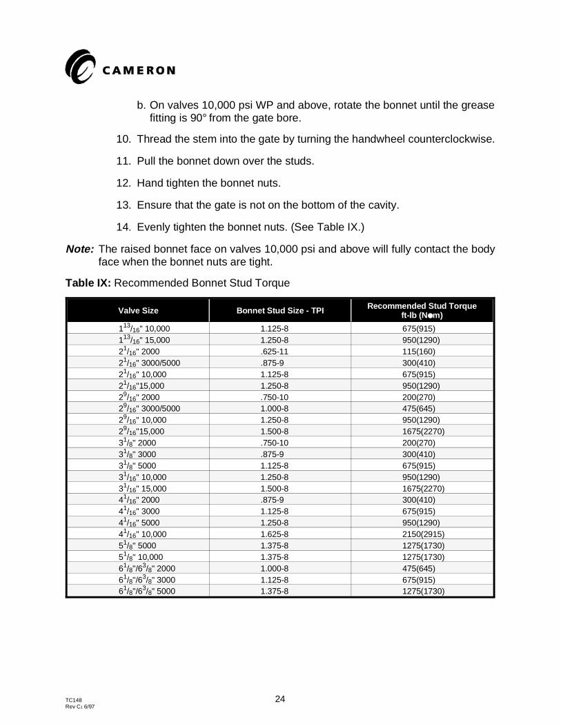
14. Evenly tighten the bonnet nuts. (See Table IX.)
Note: The raised bonnet face on valves 10,000 psi and above will fully contact the bodyface when the bonnet nuts are tight.
Table IX: Recommended Bonnet Stud Torque
Valve Size Bonnet Stud Size - TPI Recommended Stud Torqueft-lb (N ●m)
113/16" 10,000 1.125-8 675(915)113/16" 15,000 1.250-8 950(1290)21/16" 2000 .625-11 115(160)21/16" 3000/5000 .875-9 300(410)21/16" 10,000 1.125-8 675(915)21/16"15,000 1.250-8 950(1290)29/16" 2000 .750-10 200(270)29/16" 3000/5000 1.000-8 475(645)29/16" 10,000 1.250-8 950(1290)29/16"15,000 1.500-8 1675(2270)31/8" 2000 .750-10 200(270)31/8" 3000 .875-9 300(410)31/8" 5000 1.125-8 675(915)31/16" 10,000 1.250-8 950(1290)31/16" 15,000 1.500-8 1675(2270)41/16" 2000 .875-9 300(410)41/16" 3000 1.125-8 675(915)41/16" 5000 1.250-8 950(1290)41/16" 10,000 1.625-8 2150(2915)51/8" 5000 1.375-8 1275(1730)51/8" 10,000 1.375-8 1275(1730)61/8"/63/8" 2000 1.000-8 475(645)61/8"/63/8" 3000 1.125-8 675(915)61/8"/63/8" 5000 1.375-8 1275(1730)
TC148 24Rev C1 6/97
VIII. ORDERING REPLACEMENT PARTS
The only information needed for ordering replacement parts for a Cameron gate valveis the original valve assembly part number and the description of the part. The valveassembly part number is stamped on the valve body nameplate. It is recommendedthat a description of the valve assembly (size, pressure, trim) be included as a checkon the assembly number, but this is not necessary if the assembly number is clearlyreadable.
It is not recommended to order replacement parts by using the part number off theold part or by referring to a file copy of the valve assembly bill-of-material. If anengineering change has been implemented to the valve assembly to replace onecomponent part number with another, the only way to ensure getting the updatedcomponent is to reference the valve assembly number and to reference the part bydescription (gate, seat, stem, etc. Part descriptions are shown in the parts list, PartI.D.). Cameron personnel can then check the latest revision of the assemblybill-of-material to obtain the appropriate and current replacement part number.
TC148 25Rev C1 6/97