manual - w. w. grainger · 1 the ec type examination certificate is demko 12 atex 1209126 with...
TRANSCRIPT

Product Manual The Essential Guide for
Safety Teams and
Instrument Operators
Part Number: 17154993-1 Edition: 1 14 December 2012

ii
Industrial Scientific Corporation. Oakdale, PA USA Shanghai, China Arras, France © 2012 Industrial Scientific Corporation All rights reserved. Published 2012

iii
Contents
General Information .................................................................................................................................................................................................. 1
Introduction ........................................................................................................................................................................................................... 1
Certifications .................................................................................................................................................................................................... 1
Specifications ....................................................................................................................................................................................................... 3
Recommended Practices .......................................................................................................................................................................................... 5
Procedures ........................................................................................................................................................................................................... 5
First Use ............................................................................................................................................................................................................... 7
Wearing the Instrument ........................................................................................................................................................................................ 7
Instrument Basics ..................................................................................................................................................................................................... 9
Unpacking the Instrument ..................................................................................................................................................................................... 9
Hardware Overview ............................................................................................................................................................................................ 10
Display Overview ................................................................................................................................................................................................ 10
Start-up and Shutdown ....................................................................................................................................................................................... 12
Instrument Preparation and Use ............................................................................................................................................................................. 15
Configuration ...................................................................................................................................................................................................... 15
Operation ............................................................................................................................................................................................................ 23
Zero, Calibration, and Bump Test .................................................................................................................................................................. 25
Alarms and Warnings .............................................................................................................................................................................................. 29
Service and Warranty ............................................................................................................................................................................................. 33
Service Instructions ............................................................................................................................................................................................ 33
Supplies.......................................................................................................................................................................................................... 33
Three-dimensional Diagrams ......................................................................................................................................................................... 33
Service Tasks ................................................................................................................................................................................................. 36
Warranty Policy .................................................................................................................................................................................................. 39
Limitation of Liability ....................................................................................................................................................................................... 39
Contact Information ................................................................................................................................................................................... Back cover

iv
Tables and Figures
Table 1.1 Certifications ............................................................................................................................................................................................. 1
Table 1.2 Warnings and cautionary statements ....................................................................................................................................................... 2
Table 1.3 Sensor-type options .................................................................................................................................................................................. 2
Table 1.4 Instrument specifications .......................................................................................................................................................................... 3
Table 1.5 Sensor specifications ................................................................................................................................................................................ 3
Table 1.6. Battery properties ..................................................................................................................................................................................... 4
Table 2.1 Use and care procedures.......................................................................................................................................................................... 6
Figure 1. Probability of sensor failure by bump test frequency ................................................................................................................................. 6
Table 2.2 Securing the garment or belt clip .............................................................................................................................................................. 7
Table 3.1 Package contents ..................................................................................................................................................................................... 9
Table 3.2. Hardware overview ................................................................................................................................................................................ 10
Table 3.3 Display screen indicators and abbreviations .......................................................................................................................................... 10
Table 3.4 Start-up and shutdown ............................................................................................................................................................................ 12
Table 4.1 Configuration instruction ......................................................................................................................................................................... 16
Table 4.2 Operation instruction ............................................................................................................................................................................... 24
Table 4.3 Zero, calibration, and bump test ............................................................................................................................................................. 25
Table 5.1 Indicator overview ................................................................................................................................................................................... 29
Table 5.2 Alarm events and warnings .................................................................................................................................................................... 29
Figure 2. Disassembled Tango TX1 ....................................................................................................................................................................... 34
Figure 3. Disassembled Tango TX1 case top assembly ........................................................................................................................................ 34
Table 6.1 Key for the Tango TX1 diagram .............................................................................................................................................................. 35
Table 6.2 Service tasks ........................................................................................................................................................................................... 36
Table A.1. Sensor cross interference (percent response) ...................................................................................................................................... 40
Table A.2. ATEX and IECEx marking requirements ............................................................................................................................................... 40

1 General Information Introduction
Certifications
Specifications
Introduction
CERTIFICATIONS Each Tango TX1TM is certified by one or more certifying bodies (CBs). The approved uses for which a unit is certified appear on label(s) affixed to the instrument. When a new certification is received, it is not retroactive to any unit that does not bear the new marking on its label. Instrument certifications at the time of this document's publication are noted below (see Table 1.1). To determine for which uses a unit is certified, always refer to the unit's labels. CBs issue warnings and cautionary statements to notify the safety team and instrument operators of important information, or to restrict instrument use or service (see Table 1.2). Those items listed under the heading, "General", are issued by more than one CB or by Industrial Scientific Corporation (ISC); these apply to each unit regardless of its certifications. Additionally, those items listed under the heading of a specific CB apply to units that bear its markings.
1 The EC type examination certificate is DEMKO 12 ATEX 1209126 with marking code Ex ia I Ma and Ex ia IIC T4 Ga for equipment group and category I M1 and II 1G. 1 The Tango TX1 complies with relevant provisions of European ATEX directive 94/9/EC and EMC directive 2004/108/EC. 1 The Tango TX1 is constructed with reference to published standards of directive 2006/95/EC, to eliminate electrical risks and fulfill 1.2.7 of ANNEX II of directive 94/9/EC.
Table 1.1 Certifications
Directive or CB Area Classifications Standards
ATEX1 Ex ia I Ma Ex ia IIC T4 Ga Equipment Groups and Categories: I M1 and II 1G
EN 60079-0: 2012 EN 60079-11: 2012 EN 60079-26: 2007 EN 50303: 2000
IECEx2 Ex ia I Ma Ex ia IIC T4 Ga
IEC 60079-0: 2011 IEC 60079-11: 2011 IEC 60079-26: 2006
UL (C-US)3 Class I, Groups A, B, C, and D; Class II, Groups E, F, and G; T4; Exia Class I, Zone 0, AEx ia IIC T4
UL 913 7th Ed. UL 60079-0 5th Ed. UL 60079-11 5th Ed. CSA C22.2 No. 157
General Information
2
2 The IECEx examination certificate is IECEx UL 12.0041 with marking code Ex ia IIC T4 Ga and EX ia I Ma for hazardous locations with an ambient temperature range of -20 °C ≤ Ta ≤ +50 °C (-4 °F ≤ Ta ≤ +122 °F).
3 The Tango TX1 is UL certified according to the National Electrical Code and Canadian Electrical Code for use in Class I, Division 1 hazardous locations with an ambient temperature range of -20 °C ≤ Ta ≤ +50 °C (-4 °F ≤ Ta ≤ +122 °F).
Note: See the Appendix for ATEX and IECEx marking requirements.
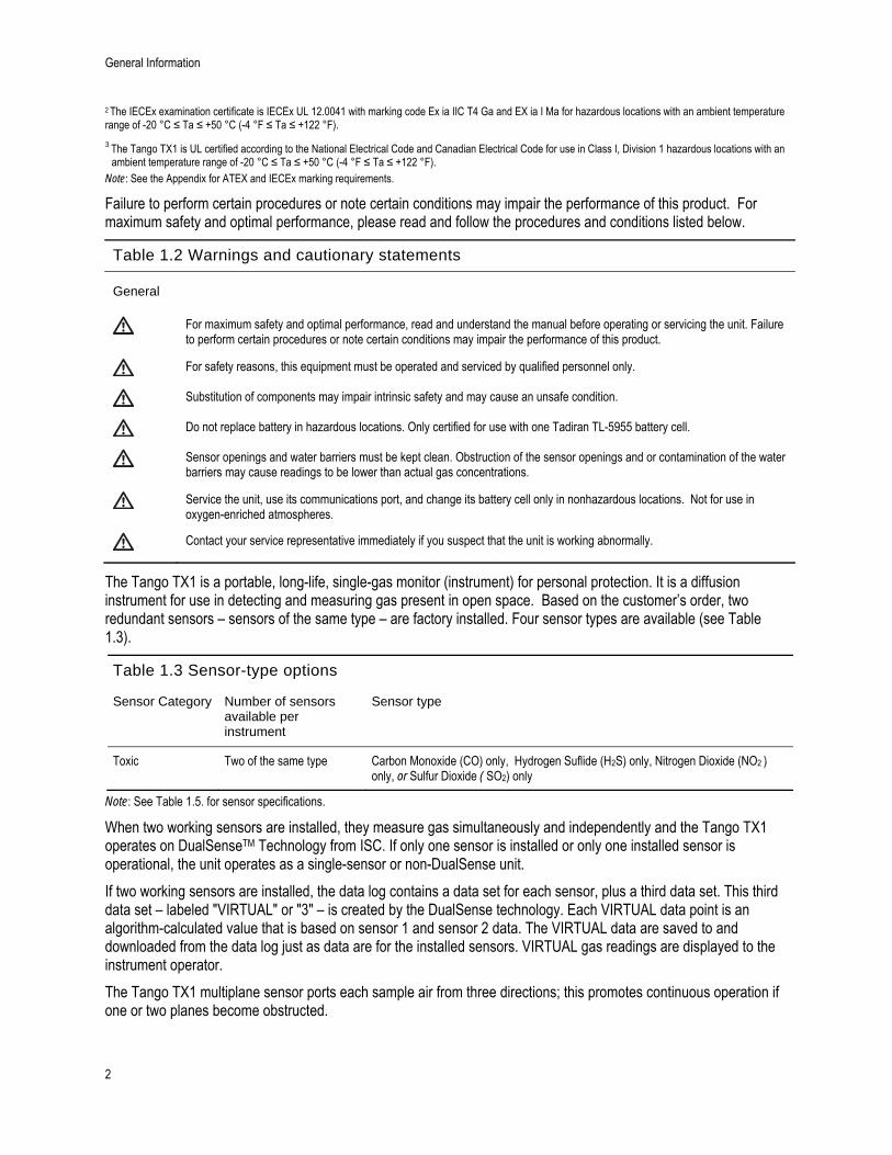
Failure to perform certain procedures or note certain conditions may impair the performance of this product. For maximum safety and optimal performance, please read and follow the procedures and conditions listed below.
Table 1.2 Warnings and cautionary statements
General
For maximum safety and optimal performance, read and understand the manual before operating or servicing the unit. Failure to perform certain procedures or note certain conditions may impair the performance of this product.
For safety reasons, this equipment must be operated and serviced by qualified personnel only.
Substitution of components may impair intrinsic safety and may cause an unsafe condition.
Do not replace battery in hazardous locations. Only certified for use with one Tadiran TL-5955 battery cell.
Sensor openings and water barriers must be kept clean. Obstruction of the sensor openings and or contamination of the water barriers may cause readings to be lower than actual gas concentrations.
Service the unit, use its communications port, and change its battery cell only in nonhazardous locations. Not for use in oxygen-enriched atmospheres.
Contact your service representative immediately if you suspect that the unit is working abnormally.
The Tango TX1 is a portable, long-life, single-gas monitor (instrument) for personal protection. It is a diffusion instrument for use in detecting and measuring gas present in open space. Based on the customer’s order, two redundant sensors – sensors of the same type – are factory installed. Four sensor types are available (see Table 1.3).
Table 1.3 Sensor-type options
Sensor Category Number of sensors available per instrument
Sensor type
Toxic Two of the same type Carbon Monoxide (CO) only, Hydrogen Suflide (H2S) only, Nitrogen Dioxide (NO2 ) only, or Sulfur Dioxide ( SO2) only
Note: See Table 1.5. for sensor specifications.
When two working sensors are installed, they measure gas simultaneously and independently and the Tango TX1 operates on DualSenseTM Technology from ISC. If only one sensor is installed or only one installed sensor is operational, the unit operates as a single-sensor or non-DualSense unit.
If two working sensors are installed, the data log contains a data set for each sensor, plus a third data set. This third data set – labeled "VIRTUAL" or "3" – is created by the DualSense technology. Each VIRTUAL data point is an algorithm-calculated value that is based on sensor 1 and sensor 2 data. The VIRTUAL data are saved to and downloaded from the data log just as data are for the installed sensors. VIRTUAL gas readings are displayed to the instrument operator.
The Tango TX1 multiplane sensor ports each sample air from three directions; this promotes continuous operation if one or two planes become obstructed.

Specifications
3
Tango TX1 measures gas at two second intervals, and continuously logs data every ten seconds. The data log can store approximately three months of data for a unit that is on 24 hours a day and has two installed, operational sensors. As the newest data are logged to memory, the oldest data are overwritten. The data log's date- and time-stamped event log records and stores event data for 60 alarm events and 30 error events. It also stores the data for up to 250 manual calibrations and bump tests. The data log is downloaded when the unit is docked in a compatible docking station.
The instrument has two modes: configuration and operation. When in configuration mode, a unit's settings can be manually edited. Entry to configuration mode can be password protected. When the instrument is on and is not in configuration mode, it is said to be in operation mode.
The instrument features an always-on option that can be enabled or disabled from configuration mode.
The Tango TX1 has a multisensory (audible, visual, and vibration), multilevel warning and alarm system. Warnings indicate a service need (calibration due) or an operating condition (confidence indicator). Alarms indicate potentially hazardous gas concentrations or system faults. Alarms can be set to latch. The instrument also features a country-of-origin option that automatically sets the values for the low-gas and high-gas alarm set points for each of five different countries or regions; each alarm set point value can also be manually edited.
The user interface consists of two buttons and an LCD (liquid crystal display). The buttons are used to power on and power off the instrument, navigate the operation and configuration loops, perform tasks, and access information. The unit can be set to display select information in English or French.
The unit's suspender clip is intended for attachment to a garment; it is not intended for attachment to a belt or hard hat. An optional belt clip is available from ISC (see "Service").
The Tango TX1 is iNet ready and compatible with the Tango TX1 iNet DS (docking station).
Specifications
Effective use of the Tango TX1 includes knowledge of the instrument's specifications and its sensor and battery specifications (see Tables 1.4. through 1.6.).
Table 1.4 Instrument specifications
Item Description
Display Segment LCD
Keypad buttons Two buttons
Case materials Case top: polycarbonate with a protective rubber over-mold Case bottom: conductive polycarbonate
Alarms Three strobe-emitting visual alarm LEDs (two red; one blue) 100 decibel (dB) audible alarm at a distance of 10 cm (3.94"), typical Vibration alarm
Dimensions 99 x 51 x 35 mm (3.9" x 2.0" x 1.4")
Weight 126.0 g (4.4 oz.), typical
Operating temperature range -20 °C to +50 °C (-4 °F to +122 °F)
Operating humidity range 15% to 95% relative humidity (RH) noncondensing (continuous)
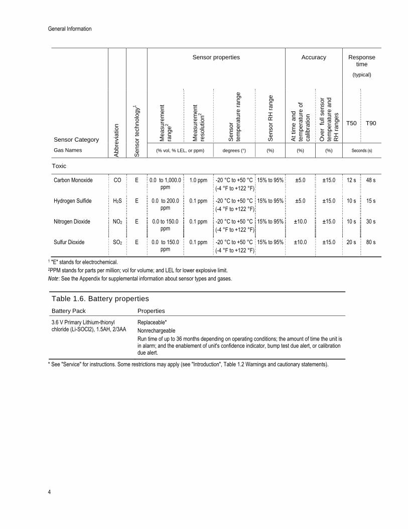
Table 1.5 Sensor specifications
General Information
4
Abb
revi
atio
n
Sen
sor
tech
nolo
gy1
Sensor properties Accuracy Response time
(typical)
Sensor Category
Gas Names
Mea
sure
men
t ra
nge2
Mea
sure
men
t re
solu
tion2
Sen
sor
tem
pera
ture
ra
nge
Sen
sor
RH
ran
ge
At t
ime
and
tem
pera
ture
of
calib
ratio
n
Ove
r fu
ll se
nsor
te
mpe
ratu
re a
nd
RH
ran
ges
T50
T90
(% vol, % LEL, or ppm) degrees (°) (%) (%) (%) Seconds (s)
Toxic
Carbon Monoxide CO E 0.0 to 1,000.0 ppm
1.0 ppm -20 °C to +50 °C (-4 °F to +122 °F)
15% to 95% ±5.0
±15.0 12 s
48 s
Hydrogen Sulfide H2S E 0.0 to 200.0 ppm
0.1 ppm -20 °C to +50 °C (-4 °F to +122 °F)
15% to 95% ±5.0
±15.0 10 s 15 s
Nitrogen Dioxide NO2 E 0.0 to 150.0 ppm
0.1 ppm -20 °C to +50 °C (-4 °F to +122 °F)
15% to 95% ±10.0
±15.0 10 s 30 s
Sulfur Dioxide SO2 E 0.0 to 150.0 ppm
0.1 ppm -20 °C to +50 °C (-4 °F to +122 °F)
15% to 95% ±10.0
±15.0 20 s 80 s
1 "E" stands for electrochemical. 2PPM stands for parts per million; vol for volume; and LEL for lower explosive limit. Note: See the Appendix for supplemental information about sensor types and gases.
Table 1.6. Battery properties
Battery Pack Properties
3.6 V Primary Lithium-thionyl chloride (Li-SOCl2), 1.5AH, 2/3AA
Replaceable* Nonrechargeable Run time of up to 36 months depending on operating conditions; the amount of time the unit is in alarm; and the enablement of unit's confidence indicator, bump test due alert, or calibration due alert.
* See "Service" for instructions. Some restrictions may apply (see "Introduction", Table 1.2 Warnings and cautionary statements).

2 Recommended Practices Procedures
First Use
Wearing the Instrument
Procedures
When completed regularly, the procedures described below help to ensure instrument operator safety. ISC provides minimum frequency recommendations for completing each procedure, depending on whether one or two operational sensors are installed (see Table 2.1).
Configuration. The configuration process allows qualified personnel to review and adjust a unit's settings.
Self-test. The self-test verifies the functionality of the unit's memory operations, battery, and each alarm indicator (audible, visual, and vibration). It does not verify sensor functionality or instrument accuracy.
"Bump Test". Bump testing is the process of briefly exposing the installed sensors to an expected concentration of calibration gas that is greater than the low alarm set point. Also referred to as a "functional test", the bump test checks only for sensor functionality; it does not measure sensor accuracy.
"Zero". A sensor zero will precede any calibration. Zeroing sets each installed sensor to recognize the ambient air as clean air. It is important to zero the instrument in truly fresh air or with a zero grade cylinder. If a toxic gas is present in the ambient air, the sensor, when zeroed, will read that level of gas as zero; until a zero is completed correctly, readings will be inaccurate.
Calibration. All sensors gradually degrade over time. This diminishes a sensor's ability to measure gas concentrations accurately; however, regular calibrations adjust the unit to compensate for this decline in sensitivity. During calibration, the installed sensors are exposed to an expected concentration of calibration gas and, when needed, the unit will self-adjust to ensure the accurate measurement and display of gas concentration values. When a sensor has degraded beyond an acceptable level, no further adjustment is possible and the sensor will no longer pass calibration.
Peak Readings. The instrument stores the highest detected gas reading, the "peak reading" or "peak". Bump testing and calibration will often register new peak readings. So, just as a zero precedes each calibration, the clearing of the peak reading should follow each calibration. The instrument operator may also wish to clear the peak reading after a bump test, before a change in location, or after an alarm is addressed and cleared.
Note: The peak readings and the data log readings are stored independently of one another; therefore, clearing the peak reading does not affect the data log. Powering the instrument off or changing its battery does not affect the peak reading. These checks and balances help promote operator safety, and serve to contain the peak readings in a "black-box" manner. In the event of a gas-related incident, this black-box record can be useful to the safety team or a prospective investigator.
ISC minimum frequency recommendations for the care and use of Tango TX1 instruments are summarized below (see Table 2.1).
Recommended Practices
6
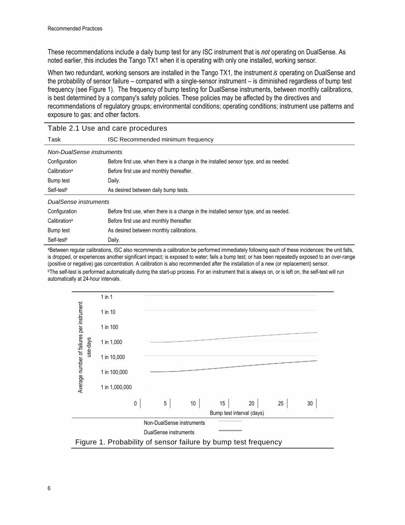
These recommendations include a daily bump test for any ISC instrument that is not operating on DualSense. As noted earlier, this includes the Tango TX1 when it is operating with only one installed, working sensor.
When two redundant, working sensors are installed in the Tango TX1, the instrument is operating on DualSense and the probability of sensor failure – compared with a single-sensor instrument – is diminished regardless of bump test frequency (see Figure 1). The frequency of bump testing for DualSense instruments, between monthly calibrations, is best determined by a company's safety policies. These policies may be affected by the directives and recommendations of regulatory groups; environmental conditions; operating conditions; instrument use patterns and exposure to gas; and other factors.
Table 2.1 Use and care procedures
Task ISC Recommended minimum frequency
Non-DualSense instruments
Configuration Before first use, when there is a change in the installed sensor type, and as needed.
Calibrationa Before first use and monthly thereafter.
Bump test Daily.
Self-testb As desired between daily bump tests.
DualSense instruments
Configuration Before first use, when there is a change in the installed sensor type, and as needed.
Calibrationa Before first use and monthly thereafter.
Bump test As desired between monthly calibrations.
Self-testb Daily. aBetween regular calibrations, ISC also recommends a calibration be performed immediately following each of these incidences: the unit falls, is dropped, or experiences another significant impact; is exposed to water; fails a bump test; or has been repeatedly exposed to an over-range (positive or negative) gas concentration. A calibration is also recommended after the installation of a new (or replacement) sensor. bThe self-test is performed automatically during the start-up process. For an instrument that is always on, or is left on, the self-test will run automatically at 24-hour intervals.
Aver
age
num
ber o
f fai
lure
s pe
r ins
trum
ent
use-
days
1 in 1
1 in 10
1 in 100
1 in 1,000
1 in 10,000
1 in 100,000
1 in 1,000,000
0 5 10 15 20 25 30
Bump test interval (days)
Non-DualSense instruments
DualSense instruments
Figure 1. Probability of sensor failure by bump test frequency

First Use
7
First Use
To prepare the Tango TX1 for first use, qualified personnel should configure and calibrate the unit.
Wearing the Instrument
Based on the U.S. Department of Labor's Occupational Safety and Health Administration (OSHA) definition of the breathing zone, it is recommended that the unit be worn within a 25.4 cm (10") radius of the nose and mouth. Refer to OSHA and to other agencies or groups as needed for additional information.
ISC also recommends that the unit be worn within the instrument operator's sight line.
The instrument operator may wear the unit with its factory-installed suspender clip or with the optional belt clip. The suspender clip is solely intended for attachment to a garment. The belt clip may be attached to a hard hat, belt, or garment.
The clips should be securely fastened and attached in a manner that ensures the unit's sensor portals are fully exposed to the air. No part of the unit should be covered by any garment, part of a garment, or other item that would restrict the flow of air to the sensors or impair the operator's access to the audible, visual, or vibration alarms.
Attach the desired clip as shown below.
Table 2.2 Securing the garment or belt clip
Suspender clip
Lift the clip cover.
Position the garment between the clip's upper and lower teeth. Press down on the clip cover to secure the clip in place.
Belt clip
Position the hard hat or garment between the clip and clip back.
Slide the clip to secure it in place. The instrument can be worn right side up or upside down.

8
3 Instrument Basics Unpacking the Instrument
Hardware Overview
Display Overview
Start-up and Shutdown
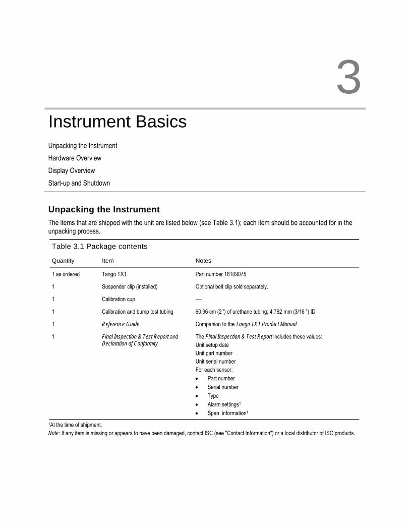
Unpacking the Instrument
The items that are shipped with the unit are listed below (see Table 3.1); each item should be accounted for in the unpacking process.
Table 3.1 Package contents
Quantity Item Notes
1 as ordered Tango TX1 Part number 18109075
1 Suspender clip (installed) Optional belt clip sold separately.
1 Calibration cup —
1 Calibration and bump test tubing 60.96 cm (2 ') of urethane tubing; 4.762 mm (3/16 ”) ID
1 Reference Guide Companion to the Tango TX1 Product Manual
1 Final Inspection & Test Report and Declaration of Conformity
The Final Inspection & Test Report includes these values: Unit setup date Unit part number Unit serial number For each sensor:
Part number
Serial number
Type
Alarm settings1
Span information1
1At the time of shipment. Note: If any item is missing or appears to have been damaged, contact ISC (see "Contact Information") or a local distributor of ISC products.

Instrument Basics
10
Hardware Overview
The instrument's main hardware components are identified below (see table 3.2).
Table 3.2. Hardware overview
Tango TX1
Visual alarm (or alert) indicator
Visual alarm (or alert) indicators
IrDA (infrared data exchange) window
Sensor port 1 and dust filter Sensor port 2 and dust filter
Case top
On-off-mode button Enter button
LCD Audible alarm (or alert) indicator and dust filter
Case bottom
Garment clip (closed)
Garment clip (open)
Display Overview The visual test screen shown below contains all the indicators that can appear on the display screen. Each indicator is stationary and appears only when relevant to the task being performed. For example, in the gas-monitoring screen shown below (numeric display), the following apply: the check mark indicates there are no sensor faults; the sensor-type icon indicates that H2S sensors are installed; the numeric display shows a gas reading of 5.1 ppm.
Table 3.3 Display screen indicators and abbreviations
Display screens
Visual test screen Gas-monitoring screen (numeric display)
Gas-monitoring screen (text display)

Display Overview
11
Item Definition
Status indicators
only Two sensors are installed and neither is in fault.
Two sensors are installed and one is in fault; a sensor location icon also displays to indicate which sensor is in fault.
and Only one sensor is installed and is not in fault.
! Two sensors are installed and both are in fault or one sensor is installed and in fault. The warning icon is also used in combination with other indicators to communicate a system alarm or an alert condition.
The unit is in configuration mode.
Alarms indicators
The alarm icon is used in combination with other indicators to communicate a variety of conditions.
and ▲ High-level gas alarm.
and ▼ Low-level gas alarm.
and STEL alarm.
and TWA alarm.
and Positive over-range gas alarm.
and Negative over-range gas alarm.
Low battery alarm.
Security code is set or to be entered. In configuration mode, indicates a feature may be operation-mode enabled or disabled.
Peak reading.
Process and time-based indicators
The zero icon is used in combination with other indicators to communicate sensor zero information.
The bump test icon is used in combination with other indicators to communicate bump test information.
The calibration icon is used in combination with other indicators to communicate calibration information.
A process is in progress. In configuration mode, indicates a time-based setting (e.g. bump test response time).
Used in combination with other indicators to communicate overdue warnings. In configuration mode, indicates a date-based setting (e.g., bump test interval).
Gas name and unit of measure abbreviations
Carbon Monoxide (CO)
Sulfur Dioxide (SO2 or SO2)
Nitrogen Dioxide (NO2 or NO2)
Hydrogen Sulfide (H2S or H2S)
PPM Parts per million is the unit of measure for CO, SO2, NO2, and H2S.

Instrument Basics
12
Table 3.3 Display screen indicators and abbreviations
Other abbreviations
Positive over-range: the detected gas concentration is greater than the upper limit measurement range of the sensor. Display variations: “Or” (English) and “Sup” (French).
Negative over-range: the detected gas concentration is less than the lower limit measurement range of the sensor. Display variations: “-Or” (English) and “InF” (French).
Short-term exposure limit. Display variations: “STEL” ( English) and “VLE” (French).
Time-weighted average. Display variations: “TWA” (English) and “VME” (French).
Start-up and Shutdown
The start-up and shutdown sequences are outlined below and feature reproductions of the display screens the instrument operator will see during these processes (see Table 3.4). Instructions accompany any display screen where the instrument operator must press a button to proceed.
The instrument operator may be prompted to complete the time- and date-setting tasks during start-up. This may happen after a battery has been removed or changed. If prompted by the unit to do so, it is essential – for data log accuracy – that the time- and date-setting tasks be completed. The data log plays an important role in preserving operator safety and in the prospective investigation of an incident.
The instrument operator may be prompted to enter a security code during shutdown. This will occur if the unit is configured for "always-on" and is security code protected.
Table 3.4 Start-up and shutdown
Start-up.
Press and hold for three seconds, then release to initiate the start-up sequence and power on the unit.
If all start-up diagnostics pass, the audio, visual, and vibration indicators turn on then off. Four start-up screens display followed by the gas-monitoring screen.
If any start-up diagnostic fails, an error message displays (see "Alarms and Warnings").
Start-up screens.
Visual test screen Version display screen Calibration date screen
(last calibration date shown above)
Countdown screen For qualified personnel only: During the 15-second countdown, press both buttons and hold for three seconds to enter configuration mode (see "Configuration").

Start-up and shutdown
13
Table 3.4 Start-up and shutdown Gas-monitoring screen.
No-fault indicator Gas concentration
Installed sensor type Unit of measure
What to do if the time setting screen is activated.
Time setting
This display screen features the clock icon and the current time setting. The instrument's clock uses a 24-hour time format. Its values are edited in this order using these ranges*: Hours: 00 to 24 Minutes: 00 to 59
The first press activates the first value to be edited. Continued presses increment the value; hold to speed the increment pace.
One press saves the displayed value and activates the next value to be edited. Continue to use the buttons, and , to edit and save the values, respectively.
After all values are edited and saved, one press activates the next configuration-mode screen.
Date setting
This display screen features the calendar icon and the current date setting. The year is displayed in the lower left corner. In the main display, the first two digits represent the date and the second two digits represent the month. The values are edited in this order using these ranges: Year: 2012 to 9999 Day: 00 to 31 Month: 00 to 12
The first press activates the first value to be edited. Continued presses increment the value; hold to speed the increment pace.
One press saves the displayed value and activates the next value to be edited. Continue to use the buttons, and , to edit and save the values, respectively.
After all values are edited and saved, one press activates the gas-monitoring screen.
Shutdown.
Press and hold for five seconds.
Countdown
After a five-second countdown: The instrument powers off if
the always-on feature is disabled or
the always-on feature is enabled and the security code is set to 000.
Instrument Basics
14
Table 3.4 Start-up and shutdown
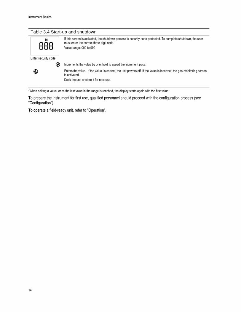
Enter security code
If this screen is activated, the shutdown process is security-code protected. To complete shutdown, the user must enter the correct three-digit code. Value range: 000 to 999
Increments the value by one; hold to speed the increment pace.
Enters the value. If the value is correct, the unit powers off. If the value is incorrect, the gas-monitoring screen is activated. Dock the unit or store it for next use.
*When editing a value, once the last value in the range is reached, the display starts again with the first value.
To prepare the instrument for first use, qualified personnel should proceed with the configuration process (see "Configuration").
To operate a field-ready unit, refer to "Operation".

4 Instrument Preparation and Use Configuration
Operation
Instructions
Zero, Calibration, and Bump Testing
Configuration
Read and understand all configuration instruction before configuring the unit.
As noted in "Recommended Practices", the unit should be configured before first use, when there is a change in the installed sensor type (e.g., H2S sensors are replaced with CO sensors), and as needed. Only qualified personnel should access the configuration mode and adjust the unit's settings.
Review the unit's configured settings for compliance with company policy and any applicable regulations, laws, and guidelines as issued by regulatory agencies and government or industry groups. Determine which settings, if any, require adjustment.
Choose alarm- and warning-related options that maximize safety within the air-sampling environment.
When the unit is in configuration mode, the following apply:
The tool icon ( ) displays in the lower right corner of each screen.
With successive short presses of the on-off-mode button ( ), the user can scroll through the configuration loop.
The enter button is used to start the editing process or start a task (e.g., zero).
When editing a value, the enter button ( ) increments the value and the on-off-mode button ( ) saves the value.
When editing a value, once the last value in the range is reached, the display starts again with the first value.
When both buttons ( and ) are simultaneously pressed and held for three seconds, the unit leaves configuration mode; it enters operation mode and the gas-monitoring screen is activated.
Unless otherwise noted, when no button is pressed for 30 seconds, the unit enters operation mode and the gas-monitoring screen is activated.
Any changes made in configuration mode are automatically saved to the unit and take effect immediately. Upon next docking, settings are updated according to the unit's settings in iNet Control.
The configuration-mode loop is outlined below (see Table 4.1). Instructions for button use accompany each configuration-mode display screen.

Instrument Preparation and Use
16
Table 4.1 Configuration instruction
Screen
Button
Description
Button effect
Enter security code
If this display screen is activated, the configuration mode is security-code protected. To enter configuration, the user must enter the correct three-digit code. If the security code is set to 000, entry to configuration mode is not security-code protected. The first configuration-mode screen is activated, the initiate-zero screen.
Increments the value by one; hold to speed the increment pace.
Saves the displayed value.
Notes: If an incorrect code is entered, the unit does not enter configuration mode and the gas-monitoring screen is activated. If the security code is unknown, configuration mode can be accessed as follows: enter 412, then press both buttons simultaneously and hold briefly. This activates the next configuration mode screen. This also resets the security code to 000, leaving configuration mode unprotected. The security code can be reset in configuration mode at the security-code-setting screen.
Initiate zero
This screen's activation allows the technician to complete the zero and calibration processes from configuration mode.
Starts the zero process.
Skips the zero process and activates the next configuration-mode screen.
Low gas alarm set point
See also country-of-origin setting. This display screen features the low alarm and sensor-type icons, and the alarm's current set point and unit of measure. The alarm set point can be edited based on the following: Value range = within the sensor measurement range Value increment = sensor measurement resolution See Table 1.5 for the measurement range and resolution for the installed sensor type.
The first press activates the value. Continued presses increment the value; hold to speed the increment pace.
One press saves the displayed value; a second press activates the next configuration-mode screen.
High gas alarm set point
See also country-of-origin setting. This display screen features the high alarm and sensor-type icons, and the alarm's current set point and unit of measure. The alarm set point can be edited based on the following: Value range = within the sensor measurement range Value increment = sensor measurement resolution See Table 1.5 for the measurement range and resolution for the installed sensor type.
The first press activates the value. Continued presses increment the value; hold to speed the increment pace.
One press saves the displayed value; a second press activates the next configuration-mode screen.

Configuration
17
Table 4.1 Configuration instruction
Screen
Button
Description
Button effect
TWA operation-mode setting
This display screen features the lock icon to indicate the technician can enable or disable the option for operation-mode access. When enabled, the instrument operator is permitted to view and clear the unit's TWA reading while the unit is in operation mode. Values: 0 = disabled 1 = enabled
Increments the value.
One press saves the displayed value and activates the next configuration-mode screen.
TWA alarm set point
This display screen features the alarm and sensor-type icons, and the alarm's current set point and unit of measure. The alarm set point can be edited. Value increment = within the sensor measurement resolution See Table 1.5 for more information about the installed sensor type.
The first press activates the value. Continued presses increment the value; hold to speed the increment pace.
One press saves the displayed value; a second press activates the next configuration-mode screen.
TWA time-base setting
This display screen features the clock and TWA icons, and the current TWA time-base. The set point value can be edited based on the following: Value range: 01 to 40 hours Value increment: 1 hour
The first press activates the value. Continued presses increment the value; hold to speed the increment pace.
One press saves the displayed value; a second press activates the next configuration-mode screen.
STEL operation-mode setting
This display screen features the lock icon to indicate the technician can enable or disable the option for operation-mode access. When enabled, the instrument operator is permitted to view and clear the unit's STEL reading while the unit is in operation mode. Values: 0 = disabled 1 = enabled
Increments the value.
One press saves the displayed value and activates the next configuration-mode screen.
STEL alarm set point
This display screen features the alarm, STEL, and sensor-type icons, and the current set point. The set point can be edited. Value increment: sensor measurement resolution See Table 1.5 for more information about the installed sensor type.
The first press activates the value. Continued presses increment the value; hold to speed the increment pace.
One press saves the displayed value; a second press activates the next configuration-mode screen.
Instrument Preparation and Use
18
Table 4.1 Configuration instruction
Screen
Button
Description
Button effect
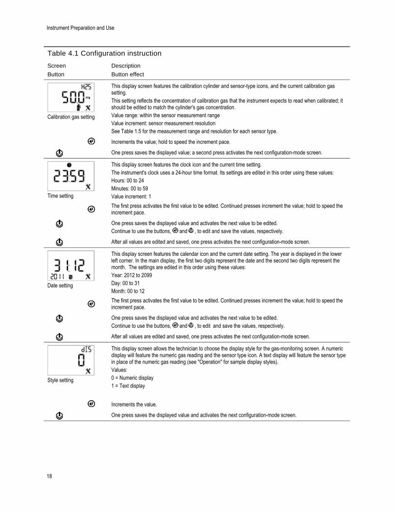
Calibration gas setting
This display screen features the calibration cylinder and sensor-type icons, and the current calibration gas setting. This setting reflects the concentration of calibration gas that the instrument expects to read when calibrated; it should be edited to match the cylinder's gas concentration. Value range: within the sensor measurement range Value increment: sensor measurement resolution See Table 1.5 for the measurement range and resolution for each sensor type.
Increments the value; hold to speed the increment pace.
One press saves the displayed value; a second press activates the next configuration-mode screen.
Time setting
This display screen features the clock icon and the current time setting. The instrument's clock uses a 24-hour time format. Its settings are edited in this order using these values: Hours: 00 to 24 Minutes: 00 to 59 Value increment: 1
The first press activates the first value to be edited. Continued presses increment the value; hold to speed the increment pace.
One press saves the displayed value and activates the next value to be edited. Continue to use the buttons, and , to edit and save the values, respectively.
After all values are edited and saved, one press activates the next configuration-mode screen.
Date setting
This display screen features the calendar icon and the current date setting. The year is displayed in the lower left corner. In the main display, the first two digits represent the date and the second two digits represent the month. The settings are edited in this order using these values: Year: 2012 to 2099 Day: 00 to 31 Month: 00 to 12
The first press activates the first value to be edited. Continued presses increment the value; hold to speed the increment pace.
One press saves the displayed value and activates the next value to be edited. Continue to use the buttons, and , to edit and save the values, respectively.
After all values are edited and saved, one press activates the next configuration-mode screen.
Style setting
This display screen allows the technician to choose the display style for the gas-monitoring screen. A numeric display will feature the numeric gas reading and the sensor type icon. A text display will feature the sensor type in place of the numeric gas reading (see "Operation" for sample display styles). Values: 0 = Numeric display 1 = Text display
Increments the value.
One press saves the displayed value and activates the next configuration-mode screen.

Configuration
19
Table 4.1 Configuration instruction
Screen
Button
Description
Button effect
Confidence indicator setting
This display screen features the alarm icon and check mark indicator. The technician can disable the indicator, or enable the indicator and choose the indicator type. When enabled, the unit will emit the selected signal every 90 seconds in operation mode. Values: 0 = disabled 1 = enabled for audible chirp 2 = enabled for blue LED flash 3 = enabled for combination audible chirp and blue LED flash
Increments the value.
One press saves the displayed value and activates the next configuration-mode screen.
Operation-mode bump test setting
This display screen features the bump test icon. The lock icon indicates the technician can enable or disable this operation-mode feature. When enabled, the instrument operator is given access to bump test the unit from operation mode. Values: 0 = disabled 1 = enabled
Increments the value.
One press saves the displayed value and activates the next configuration-mode screen.
Bump test due alert setting
This display screen features the alarm, bump test, calendar, and warning icons. The technician can disable the warning, or enable the warning and choose the warning type. When enabled, the alert screen will be activated and the unit will emit the selected indicator every 60 seconds to notify its user that a bump test is due; the instrument will continue to operate. Values: 0 = disabled 1 = enabled for audible chirp 2 = enabled for blue LED flash 3 = enabled for combination audible chirp and blue LED flash
Increments the value.
One press saves the displayed value and activates the next configuration-mode screen.
Bump test interval setting
This display screen features the bump test and calendar icons. The technician can set the interval at which the bump test due alert is to be activated. Value range: 0.5 to 30.0 days Value increment: 0.5 days
The first press activates the value. Continued presses increment the value; hold to speed the increment pace.
One press saves the displayed value; a second press activates the next configuration-mode screen.

Instrument Preparation and Use
20
Table 4.1 Configuration instruction
Screen
Button
Description
Button effect
Bump test percentage setting
This display screen features the bump test icon and the current setting. The technician can set the percentage of calibration gas to which the unit will respond. Value range: 50% to 95% Value increment: 1% See Table 1.5 for sensor information that can aid in the setting of bump test values.
The first press activates the value. Continued presses increment the value; hold to speed the increment pace.
One press saves the displayed value; a second press activates the next configuration-mode screen.
Bump test response-time setting
This display screen features the bump test and clock icons, and the current setting in seconds. A sensor passes a bump test when it senses the specified percentage of calibration gas within the specified response time setting. Value range: 30 to 120 seconds Value increment: 1 second
The first press activates the value. Continued presses increment the value; hold to speed the increment pace.
One press saves the displayed value; a second press activates the next configuration-mode screen.
Alarm latch setting
This display screen features the alarm icon and the current setting. The lock icon indicates the technician can enable or disable this operation-mode feature. When disabled, a unit in alarm will turn off its alarm when the gas reading is no longer at the alarm-producing concentration. When enabled, a unit in alarm will remain in alarm until it is manually reset. The instrument operator can reset a latched alarm from operation mode with a long press of the enter button ( ). This resets the alarm; it does not disable an enabled latch. Values: 0 = disabled 1 = enabled
Increments the value.
One press saves the displayed value and activates the next configuration-mode screen.
Vibration alarm setting
This display screen features the alarm, check mark, and vibration motor icons. When enabled, the vibrating alarm will be activated when the unit is in alarm. Values: 0 = disabled 1 = enabled
Increments the value.
One press saves the displayed value and activates the next configuration-mode screen.
Configuration
21
Table 4.1 Configuration instruction
Screen
Button
Description
Button effect
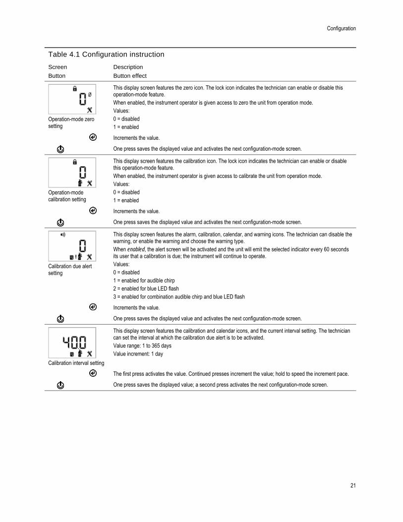
Operation-mode zero setting
This display screen features the zero icon. The lock icon indicates the technician can enable or disable this operation-mode feature. When enabled, the instrument operator is given access to zero the unit from operation mode. Values: 0 = disabled 1 = enabled
Increments the value.
One press saves the displayed value and activates the next configuration-mode screen.
Operation-mode calibration setting
This display screen features the calibration icon. The lock icon indicates the technician can enable or disable this operation-mode feature. When enabled, the instrument operator is given access to calibrate the unit from operation mode. Values: 0 = disabled 1 = enabled
Increments the value.
One press saves the displayed value and activates the next configuration-mode screen.
Calibration due alert setting
This display screen features the alarm, calibration, calendar, and warning icons. The technician can disable the warning, or enable the warning and choose the warning type. When enabled, the alert screen will be activated and the unit will emit the selected indicator every 60 seconds its user that a calibration is due; the instrument will continue to operate. Values: 0 = disabled 1 = enabled for audible chirp 2 = enabled for blue LED flash 3 = enabled for combination audible chirp and blue LED flash
Increments the value.
One press saves the displayed value and activates the next configuration-mode screen.
Calibration interval setting
This display screen features the calibration and calendar icons, and the current interval setting. The technician can set the interval at which the calibration due alert is to be activated. Value range: 1 to 365 days Value increment: 1 day
The first press activates the value. Continued presses increment the value; hold to speed the increment pace.
One press saves the displayed value; a second press activates the next configuration-mode screen.

Instrument Preparation and Use
22
Table 4.1 Configuration instruction
Screen
Button
Description
Button effect
Calibration date setting
This display screen features the calibration cylinder, calendar, warning, and arrow icons. The technician can choose whether the operation-mode calibration date screen will display the due date for the unit's next calibration or the date of the unit's last calibration. The up arrow ( ▲) will be featured on-screen when the unit is set to display the next the calibration due. The down arrow (▼) will be featured when the unit is set to display the last calibration date. Values: 0 = displays date of last calibration 1 = displays next calibration due date
Increments the value.
One press saves the displayed value and activates the next configuration-mode screen.
Security code setting
This display screen features the lock icon and the current security code. The security code controls two things: access to a unit's configuration mode and the ability to power off a unit that is configured for always-on operation. If the security code is set at 000, entry to configuration mode is not security-code protected, and an always-on unit can be powered off without a security code. Any other value will enable the security code. Value range: 000 to 999 Value increment: 1
The first press activates the value. Continued presses increment the value; hold to speed the increment pace.
One press saves the displayed value; a second press activates the next configuration-mode screen.
Country-of-origin setting
This display screen features the country-of-origin icon and the current setting. This feature sets automatically the low- and high-gas alarm set points. The technician must choose one of these options: “DEF” = USA and default value “CAn” = Canada “EUr” = Europe “CR” = Czech Republic “AUS” = Australia The unit's settings are immediately updated to reflect that county's (or Europe's) low- and high-gas alarm set points for the installed sensor-type. When the country-of-origin selection does not contain a value for an alarm set point, the default value (DEF) is automatically substituted.
The first press activates the value. Continued presses increment the value; hold to speed the increment pace.
One press saves the displayed value and activates the next configuration-mode screen.
Notes: Each alarm setting can be edited individually, in configuration mode, at that alarm's set point screen. Because low- and high-gas alarm set points can be edited both individually and through the country-of-origin option, it is important to understand override behavior. Example. The H2S low-gas alarm set point was edited – at its set point screen – to a value of 9 ppm. Afterwards, a country-of-origin selection was made where the H2S low-gas alarm set point value is 10 ppm. The last-entered setting overrides the first. Therefore, in this example, the value of the H2S low gas alarm set point is 10 ppm. Another aspect to alarm settings applies to replacement or new sensors. For example:
If the installed H2S sensor(s) is replaced with other H2S sensor(s), the last-entered low-gas alarm set point (a value of 10 ppm in the above example) will be applied to the newly installed sensor(s).
If the installed H2S sensors are replaced with a different sensor type (e.g., CO), the alarm settings will be read from the newly installed sensor(s).
Configuration
23
Table 4.1 Configuration instruction
Screen
Button
Description
Button effect
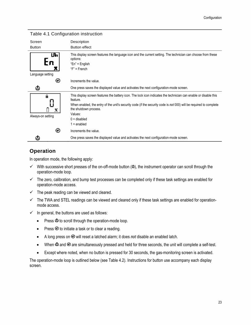
Language setting
This display screen features the language icon and the current setting. The technician can choose from these options: “En” = English “F” = French
Increments the value.
One press saves the displayed value and activates the next configuration-mode screen.
Always-on setting
This display screen features the battery icon. The lock icon indicates the technician can enable or disable this feature. When enabled, the entry of the unit's security code (if the security code is not 000) will be required to complete the shutdown process. Values: 0 = disabled 1 = enabled
Increments the value.
One press saves the displayed value and activates the next configuration-mode screen.
Operation
In operation mode, the following apply:
With successive short presses of the on-off-mode button ( ), the instrument operator can scroll through the operation-mode loop.
The zero, calibration, and bump test processes can be completed only if these task settings are enabled for operation-mode access.
The peak reading can be viewed and cleared.
The TWA and STEL readings can be viewed and cleared only if these task settings are enabled for operation-mode access.
In general, the buttons are used as follows:
Press to scroll through the operation-mode loop.
Press to initiate a task or to clear a reading.
A long press on will reset a latched alarm; it does not disable an enabled latch.
When and are simultaneously pressed and held for three seconds, the unit will complete a self-test.
Except where noted, when no button is pressed for 30 seconds, the gas-monitoring screen is activated.
The operation-mode loop is outlined below (see Table 4.2). Instructions for button use accompany each display screen.

Instrument Preparation and Use
24
Table 4.2 Operation instruction
Screen
Buttons
Screen description
Button effects
Gas monitoring
This display screen (numeric shown) features the check mark and sensor-type icons, and the current gas reading and unit of measure. The check mark indicates the unit is operational and there are no sensor faults.
One short press turns on the backlight if the unit senses it is not in a well-lit environment. When the unit is in alarm, a long press will reset a latched alarm; the alarm will recur if the alarm-causing condition is still present.
Activates the next enabled operation-mode screen.
Calibration date
This display screen features the calibration, calendar, and check mark icons, an up or down arrow, and a date value. When the up arrow (▲) is featured, the next calibration date is displayed. When the down arrow (▼) is featured, the last calibration date is displayed. Values: Date: XX (day) and XX (month) Year: XXXX
No effect.
Activates the next enabled operation-mode screen.
Initiate zero
This display screen is activated if the unit is enabled for operation-mode zeroing. It features the check mark and zero icons.
Starts the zero process (see "Zero, Calibration, and Bump Testing").
Activates the next enabled operation-mode screen.
Initiate bump test
This display screen is activated if the unit is enabled for operation-mode bump testing. The screen features the check mark and bump test icons.
Starts the bump test process (see "Zero, Calibration, and Bump Testing").
Activates the next enabled operation-mode screen.
Peak reading
This display screen features the check mark, peak, and sensor-type icons, and the most recent peak reading.
Clears the peak reading.
Activates the next enabled operation-mode screen.

Operation
25
TWA reading
This display screen is activated if this feature is operation-mode enabled. The screen features the check mark, sensor-type, and TWA icons, and the current TWA reading.
Clears the TWA reading.
Activates the next enabled operation-mode screen.
STELreading
This display screen is activated if this feature is operation-mode enabled. The screen features the check mark, sensor-type, and STEL icons, and the current STEL reading.
Clears the STEL reading.
Activates the next enabled operation-mode screen.
ZERO, CALIBRATION, AND BUMP TEST
Perform the zero, calibration, and bump testing tasks in an area known to be nonhazardous.
Table 4.3 Zero, calibration, and bump test
Supplies, preparation, and instruction
Supplies
Calibration cup (shipped with the unit)
Calibration tubing (shipped with the unit)
Calibration gas cylinder suitable for the installed sensors and the unit's calibration gas settings
Positive flow regulator suitable for the calibration gas cylinder
Preparation
Holding the regulator, turn the calibration gas cylinder in a clockwise direction to tighten.
Connect either end of the calibration tubing to the regulator's nipple.
Connect the other end of the tubing to the calibration cup. Proceed with the instruction set below for the desired task: zero and calibration or bump test.

Instrument Preparation and Use
26
Table 4.3 Zero, calibration, and bump test
Supplies, preparation, and instruction
Instruction
Zero
Initiate zero
Zero in-progress
Zero results (pass)
Zero results (fail)
Note: From anywhere in the operation-mode loop, press until the initiate-zero screen is activated. At the initiate-zero screen, press
to start the zero process.
While the sensors are zeroed, the zero-in-progress screen is activated.
After the sensors are zeroed, the zero-results screen is activated and an audible alert is emitted. If the result for either sensor is an "F" for fail, press to reactivate the initiate-zero screen. Repeat the zero process. If the result for both sensors is a "P" for pass, press to display the initiate-calibration screen. If calibration is not desired, wait approximately 30 seconds for the zero-results screen to deactivate; the gas-monitoring screen will be automatically activated.
Calibration
Initiate calibration
Calibration apply gas
Place the calibration cup over the case top; align its top groove with the small ridge at the top of the instrument. Press down to secure the cup in place; a click will sound. Visually inspect the calibration cup to ensure its edges along the top and sides align with the case top edges.
To start the calibration process, press . Both sensors will be calibrated simultaneously. To cancel the calibration, press
.
Once the calibration is started, the apply-gas screen is activated; the expected type and concentration of calibration gas are displayed. This screen remains activated for up to 5 minutes as the unit awaits the application of calibration gas. To cancel the calibration, press
.
Calibration in progress
Calibration results (pass)
Calibration results (fail)
To start the flow of gas, turn the regulator knob in a counterclockwise direction. While the sensors are calibrated, the calibration-in-progress screen displays the span reserve value. If desired, press to cancel the calibration.
If at least one sensor passes calibration, two results screens are alternately activated; one indicates the pass or fail result for each sensor and the other displays the span reserve value. If neither sensor passes calibration, the audible, visual, and vibrating alarms turn on. Two results screens are alternately activated; one indicates the fail results and the other displays the span reserve value. Note: With two installed, working sensors, the span reserve value is the algorithm calculation of the DualSense Technology.

Operation
27
Table 4.3 Zero, calibration, and bump test
Supplies, preparation, and instruction
Span reserve value
If at least one sensor passes the calibration, the gas-monitoring screen will be automatically activated. Note: The span reserve value divided by the calibration gas concentration yields the span reserve percentage. A span reserve percentage of greater than 70% indicates a “good” sensor; 50%-70% indicates “marginal” sensitivity. When the span reserve percentage is less than 50%, the sensor will not pass calibration.
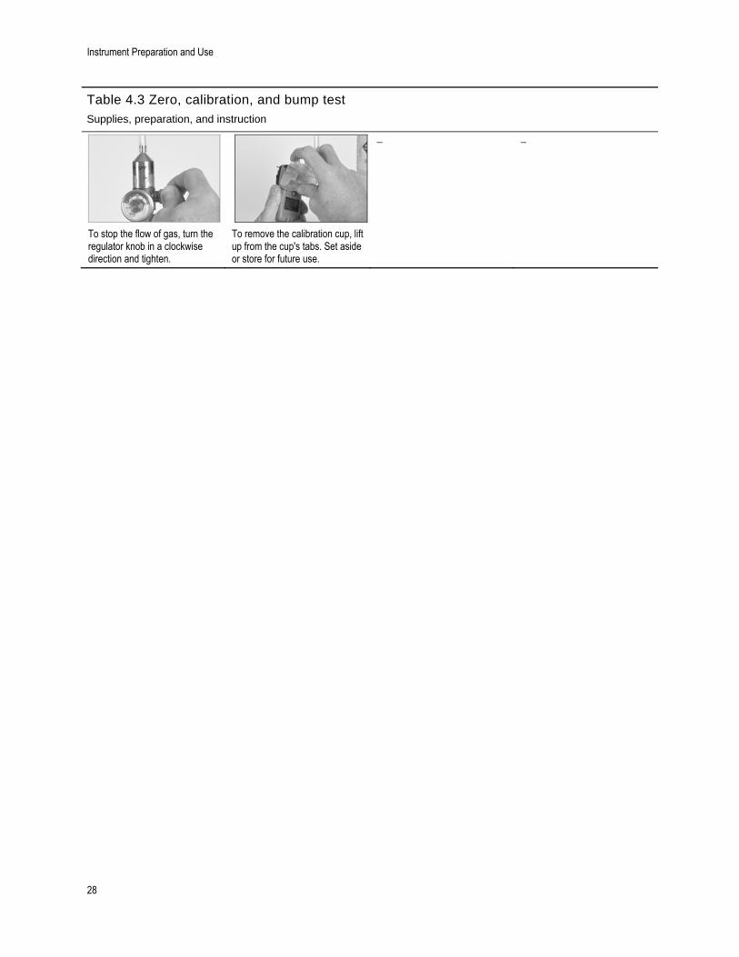
To stop the flow of gas, turn the regulator knob in a clockwise direction and tighten.
To remove the calibration cup, lift up from the cup's tabs. Set aside or store for future use.
Bump testing
Initiate bump test
Bump test apply gas
Place the calibration cup over the case top; align its top groove with the small ridge at the top of the instrument. Press down to secure the cup in place; a click will sound. Visually inspect the calibration cup to ensure its edges along the top and sides align with the case top edges.
Note: From anywhere in the operation-mode loop, press until the initiate-bump-test screen is activated. Press to start the bump test process. Press to cancel the bump test.
Once the bump test is started, the apply-gas screen is activated; the expected type and concentration of calibration gas are displayed. This screen remains activated for up to 5 minutes as the unit awaits the application of calibration gas.
Bump test in progress
Bump test results (pass)
Bump test results (fail)
To start the flow of gas, turn the regulator knob in a counterclockwise direction.
If either or both sensors fail the bump test, the calibration due warning screen will be automatically activated. Calibrate the instrument. If both sensors pass the bump test, the gas-monitoring screen will be automatically activated.
Instrument Preparation and Use
28
Table 4.3 Zero, calibration, and bump test
Supplies, preparation, and instruction
To stop the flow of gas, turn the regulator knob in a clockwise direction and tighten.
To remove the calibration cup, lift up from the cup's tabs. Set aside or store for future use.

5 Alarms and Warnings
There are four levels of alarm. From highest to lowest, they are: system, high-level, low-level, and low-battery alarms. Alarm and warning indicators are summarized below (see Table 5.1).
Table 5.1 Indicator overview
Alarm Audible Visual (LEDs) Vibration Enunciation
System alarm Yes Red only Yes* Continuous sequence High-level alarm Yes Red only Yes* Continuous sequence Low-level alarm Yes Red and blue Yes* Continuous sequence with pauses Low-battery alarm Yes Red only No Intermittent Warnings Yes* Blue only* No Intermittent
The system and the high- and low-level alarms can each be caused by several possible alarm events. An alarm event is distinguished by its display screen. The display screen reproduction, possible causes, and recommended actions for each alarm event – and for warnings – are outlined below (see Table 5.2).
Table 5.2 Alarm events and warnings
Event type Possible causes Recommended actions
System alarms.
Sample system alarm event screen
A critical hardware or system fault has occurred. Note: The "483" value shown here represents a specific error code (both sensors in fault). The code number will vary based on the system alarm event that has occurred (see below).
The unit is not operational. Leave the area. Respond according to company safety policy and guidelines. See an on-site supervisor or contact ISC Technical Support (see "Contact Information").
Error codes for several sensor-related system alarm events include: In addition to the recommended actions noted above, the following apply to the error codes 406, 408, 483, and 499: Qualified personnel can complete any of the following (see "Service"):
Check each installed sensor for instrument compatibility.
If two sensors are installed, check to see that they match.
Check each installed sensor for proper installation.
Install the required sensors.
406: illegal sensor position. The instrument does not accept the installed sensor type.
408: no sensors found. No sensors are installed or the installed sensors are not detected by the unit.
483: both sensors in fault. Neither sensor is operational.
499: sensor-type mismatch. The installed sensors are not of the same type.

Alarms and Warnings
30
Table 5.2 Alarm events and warnings
Event type Possible causes Recommended actions
High-level alarms.
Over-range gas alarm event (positive shown)
The gas concentration is outside of the sensor's measuring range. Note: For a negative over-range condition, the "—OR" icon displays.
Leave the area. Respond according to company safety policy and guidelines. Note: Once the gas concentration is within the sensor's measuring range, the alarm indicators will change to reflect any new condition such as high-gas alarm, low-gas alarm, or no gas alarm.
High-alarm gas event
The detected gas concentration exceeds the higg- alarm set point.
Leave the area. Respond according to company safety policy and guidelines. Note: Once the gas concentration changes and is below or above the high alarm set point, the alarm indicators will change to reflect any new condition such as low gas alarm, over-range gas alarm, or no gas alarm.
STEL alarm event
The unit has reached its maximum exposure for the configured STEL settings.
Leave the area. Respond according to company safety policy and guidelines.
Low-level alarms.
TWA alarm event
The unit has reached its maximum exposure for the configured TWA settings.
Leave the area. Respond according to company safety policy and guidelines.
Low -alarm gas event
The detected gas concentration exceeds the low-alarm set point.
Leave the area. Respond according to company safety policy and guidelines. Note: Once the detected gas concentration changes and is below or above the low-alarm set point, the alarm indicators will change to reflect any new condition such as high-gas alarm, or over-range gas alarm, or no gas alarm.
Low-battery alarm.
Low-battery alarm event
There are fewer than 96 hours of remaining battery life. The battery-warning icon appears on the unit's display. The audible indicator and a red LED turn on and off every minute for the first 72 hours of the alarm condition. During the last 24 hours, these indicators continue but at a faster pace. The unit is operational. After 96 hours, the battery has reached its end of life and the unit is not operational. The indicators noted above, along with the vibration indicator, turn on and off for approximately 10
After 96 hours from the initial alarm indication, the unit is not operational. Respond according to company safety policy and guidelines. Qualified personnel can refer to "Service" to complete the battery replacement task. Note: Once started, if the battery replacement task is not completed with 60 minutes, the following will occur:
Any data will be lost that was not downloaded prior to the start of the task.
Alarms
31
Table 5.2 Alarm events and warnings
Event type Possible causes Recommended actions
Dead battery indicator
minutes. The red LEDs will then turn on and off simultaneously for approximately 24 hours.
The unit's time and date settings will be erased. When these settings are erased, the user will be prompted, during the next start-up sequence, to enter the correct time and date.
Note: It is essential—for data log accuracy—that these tasks be completed. The data log plays an important role in preserving operator safety, and in the investigation of any potential incident, it can be useful to the safety team or a prospective investigator.
Warnings.
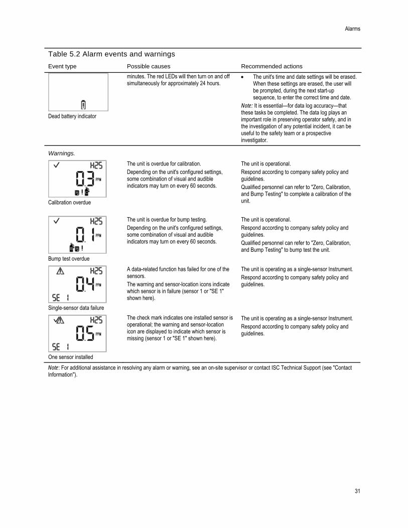
Calibration overdue
The unit is overdue for calibration. Depending on the unit's configured settings, some combination of visual and audible indicators may turn on every 60 seconds.
The unit is operational. Respond according to company safety policy and guidelines. Qualified personnel can refer to "Zero, Calibration, and Bump Testing" to complete a calibration of the unit.
Bump test overdue
The unit is overdue for bump testing. Depending on the unit's configured settings, some combination of visual and audible indicators may turn on every 60 seconds.
The unit is operational. Respond according to company safety policy and guidelines. Qualified personnel can refer to "Zero, Calibration, and Bump Testing" to bump test the unit.
Single-sensor data failure
A data-related function has failed for one of the sensors. The warning and sensor-location icons indicate which sensor is in failure (sensor 1 or "SE 1" shown here).
The unit is operating as a single-sensor Instrument. Respond according to company safety policy and guidelines.
One sensor installed
The check mark indicates one installed sensor is operational; the warning and sensor-location icon are displayed to indicate which sensor is missing (sensor 1 or "SE 1" shown here).
The unit is operating as a single-sensor Instrument. Respond according to company safety policy and guidelines.
Note: For additional assistance in resolving any alarm or warning, see an on-site supervisor or contact ISC Technical Support (see "Contact Information").

32

6 Service and Warranty Service Instructions
Supplies
Three-dimensional Diagrams
Service Tasks
Warranty Policy
Limitation of Liability
Service Instructions
Perform all service tasks on a nonconductive surface in a well-lit area that is known to be nonhazardous.
Wear grounding straps to prevent electrostatic discharge (ESD) which can cause damage to the unit's electronics.
When working with the adhesive-backed filters and gaskets:
Be careful not to pierce or tear these items.
When using tweezers, apply gentle pressure.
Once the adhesive touches a surface, any attempt to remove or reposition the item may cause it damage.
When working with sensors and the case top's water barriers:
Do not touch the white membranes as this can contaminate these items.
Use care not to damage the membranes.
Use care not to separate the sensor from its membrane.
SUPPLIES
Hex screwdriver (for case bottom screws)
Philips screwdriver (for clip screw)
Needle-nose tweezers (for barrier and filter service tasks)
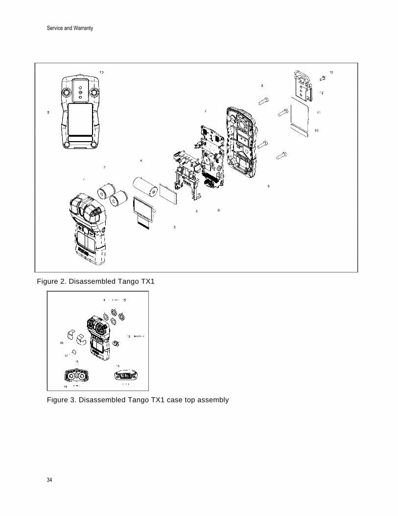
THREE-DIMENSIONAL DIAGRAMS
Refer to the three-dimensional diagrams for disassembled views of the instrument and its case top assembly. Use the diagram number to identify parts, part numbers, and field-replaceable items (see Table 6.1).
Service and Warranty
34
Figure 2. Disassembled Tango TX1
Figure 3. Disassembled Tango TX1 case top assembly

Service Instructions
35
Table 6.1 Key for the Tango TX1 diagram
Diagram number
Part name Field replaceable
Part number Notes
-- Case top assembly The case top can be replaced as a single assembly that includes the parts labeled with diagram numbers: 1, 14, 15, 16, and 17. These components are also sold separately.
Yes 17153951 Assembly includes case top (17153952); sensor water barriers and gaskets (17154219 and 17154051, respectively); and sensor and audible alarm dust barriers (17154540 and 17154581, respectively).
1 Case top Yes 17153952
14 Sensor water barrier Yes 17154219 Parts 17154219 and 17154051 should be replaced at the same time. Kit 18109230 contains 10 barriers and 10 gaskets.
15 Sensor water barrier gasket Yes 17154051
16 Sensor dust barrier Yes 17154540 Kit 18109218 contains 10 sensor dust barriers and 5 audible alarm dust barriers. Notes: The dust barriers are not water impenetrable. More frequent replacement service may be needed in harsh environments.
17 Audible alarm dust barrier Yes 17154581
18 Vibration alarm motor Yes 17127275
2 Sensors Yes Varies
CO Yes 17134487
H2S Yes 17154978
NO2 Yes 17134503
SO2 Yes 17143595
4 Battery Yes 17154367
3 and 5 LCD No* 17153786
6 and 7 Board assembly No*
10 and 11 Unit labels No*
12 Suspender clip Yes 17154484
not shown Belt clip (optional) Yes 17120908
13 Screw (for use with installed suspender clip and optional belt clip)
Yes 17139262 Torque: 81 newton cm (115 ounce-force inch)
9 Case bottom screws Yes 17154328 Torque: 85 newton cm (120 ounce-force inch)
8 Case bottom No* 17153769
*For items that are not field-replaceable, contact ISC (see "Contact Information") or a local distributor of ISC products.

Service and Warranty
36
SERVICE TASKS Table 6.2 Service tasks
Power off the unit before disassembling or performing any service task.
Instrument disassembly
Using a torx screwdriver, remove all four screws from the case bottom; set aside the screws.
Hold the case bottom near the upper screw holes; lift the case top slightly to separate the top and bottom.
Continue to lift the case top straight up to remove it and to avoid unintentionally loosening the sensors. If replacing just the case top, refer to the task below, "Instrument assembly". Otherwise, proceed with the desired service tasks below.
Sensor port and audible alarm dust barrier replacement (sensor port dust barrier shown)
Using a finger or needle-nose tweezers, peel off the dust barrier and discard.
Place the barrier packet on the work surface. Scrape lightly across the paper to the barrier's edge; gently lift to expose a portion of its adhesive back. Peel the barrier from the packet.
Guide the new barrier—adhesive side down—onto the case top. Using a finger, press and hold for five seconds to activate the adhesive.
Sensor water barrier assembly replacement
Note. The sensor water-barrier assembly consists of two parts: the filter and its gasket. Replace both items at the same time.
Inside the case top, grip the gasket and underlying sensor filter with the needle-nose tweezers; peel to remove.
Remove any remnants of the adhesive, filter, or gasket. Clear away any dirt, dust, or debris.
Place the filter packet on the work surface. Using the tweezers, scrape lightly across the paper to the filter's edge; gently lift to expose a portion of the adhesive back. Grip the filter lightly with the tweezers; peel the filter from the packet.

Service Instructions
37
Table 6.2 Service tasks
Guide the new filter—adhesive side down—into the filter opening. For proper placement, take care to ensure the filter edge meets the inner edge of the filter opening.
Using a clean, soft cloth, press gently around the filter edge; hold for five seconds to activate the adhesive.
Place the gasket packet on the work surface. Using the tweezers, scrape lightly across the paper to the gasket ring's edge; gently lift to expose a portion of the adhesive back. Grip the gasket ring lightly with the tweezers; peel the gasket ring from the packet.
Guide the gasket—adhesive side down—into the filter opening, placing it on top of the filter. Ensure the gasket ring edge meets the outer edge of the filter opening and fully covers the white filter membrane.
Using a clean, soft cloth, press gently around the gasket edge; hold for five seconds to activate the adhesive.
Vibrating alarm motor replacement
Insert the tweezers between the case top and the motor. Pry up to remove.
Using the tweezers, gently grip the new motor. Place the new motor – contact side up – into the case top. Without touching the motor's contacts, use the tweezer handle to press the item into place.
Sensor replacement
Lift the sensor to remove it. Set aside for future use or dispose of according to company policy.
Position the sensor to align with its connector on the instrument board.
Secure the sensor in place by applying gentle pressure to the sides of the sensor case. Do not touch the sensor's white membrane. A slight connection impact can be felt when the sensor is secured into place.

Service and Warranty
38
Table 6.2 Service tasks
Battery replacement
Lift the battery up from its cradle. Dispose of according to company policy.
Orient the replacement battery so the positive and negative ends align with the "+" and "" cradle markings, respectively. Place the new battery into the cradle negative end first.
Press down on the battery to secure it in the cradle.
Clip removal and attachment (suspender clip shown)
Lift the clip's cover. Use a Philips screwdriver to access the clip's screw. Turn counterclockwise to loosen and remove the screw and washer.
Lift the clip to remove it. Close the clip; store it for future use.
To attached the clip cover, place the screw through the center hole of the clip back.
Guide the screwdriver through the clip's hole and into the screw head. Turn clockwise to tighten. Note: Refer to Table 6.1 for torque values.
Instrument assembly
Hold the case bottom near the upper screw holes.
Lower the case top assembly onto the case bottom. Use a straight-down motion to guide the sensors into the sensor barrels.
Press to secure the case top and case bottom.
Using a torx screwdriver, insert and tighten each of the four screws into the case bottom. Note: Refer to Table 6.1 for torque values.

Warranty Policy
39
Warranty Policy
Industrial Scientific Corporation’s portable Tango TX1 gas-monitoring instrument is warranted to be free from defects in material and workmanship under normal and proper use and service for three years from the initial purchase date.
The above warranty does not include the sensors, battery, or filters, but the sensors carry their own separate warranty. The factory-installed sensors are warranted to be free from defects in material and workmanship under normal and proper use and service as follows, except where otherwise stated in writing in Industrial Scientific literature accompanying the product:
CO and H2S sensors are warranted for three years from the initial purchase date.
All other sensors are warranted for two years from the initial purchase date.
LIMITATION OF LIABILITY
THE WARRANTY SET FORTH ABOVE IS STRICTLY LIMITED TO ITS TERMS AND IS IN LIEU OF ALL OTHER WARRANTIES, GUARANTEES, EXPRESS OR IMPLIED, ARISING BY OPERATION OF LAW, COURSE OF DEALING, USAGE OF TRADE OR OTHERWISE. INDUSTRIAL SCIENTIFIC MAKES NO OTHER WARRANTIES, EITHER EXPRESSED OR IMPLIED, INCLUDING BUT NOT LIMITED TO THE WARRANTIES OF MERCHANTABILITY OR FITNESS FOR PARTICULAR PURPOSE.
Should the product fail to conform to the above warranty, buyer's only remedy and Industrial Scientific’s only obligation shall be, at Industrial Scientific’s sole option, replacement or repair of such non-conforming goods or refund of the original purchase price of the non-conforming goods.
In no event will Industrial Scientific be liable for any other SPECIAL, INCIDENTAL OR CONSEQUENTIAL OR OTHER SIMILAR DAMAGES, including loss of profit or loss of use, arising out of the sale, manufacture or use of any products sold hereunder whether such claim is pleaded in contract or in tort, including strict liability in tort and whether Industrial Scientific has been advised of the potential for such damages.
Industrial Scientific’s total liability hereunder from any cause whatsoever (except liability from personal injury caused by Industrial Scientific’s negligence), whether arising under contract, warranty, tort (including negligence), strict liability, products liability or any other theory of liability, will be limited to the lesser of Buyer’s actual damages or the price paid to Industrial Scientific for the Products that are the subject of Buyer’s claim. All claims against Industrial Scientific must be brought within one year after the cause of action arises, and Buyer expressly waives any longer statute of limitations.
It shall be an express condition to Industrial Scientific's warranty that all products be carefully inspected for damage by Buyer upon receipt, be properly calibrated for Buyer's particular use, and be used, repaired, and maintained in strict accordance with the instructions set forth in Industrial Scientific's product literature. Repair or maintenance by non-qualified personnel will invalidate the warranty, as will the use of non-approved consumables or spare parts.
As with any other sophisticated product, it is essential and a condition of Industrial Scientific's warranty that all personnel using the products be fully acquainted with their use, capabilities and limitations as set forth in the applicable product literature. Buyer acknowledges that it alone has determined the intended purpose and suitability of the goods purchased.
It is expressly agreed by the parties that any technical or other advice given by Industrial Scientific with respect to the use of the goods or services is given without charge and at Buyer’s risk; therefore, Industrial Scientific assumes no obligations or liability for the advice given or results obtained.

40
Appendix Supplemental Information about Sensors and Gases
Table A.1. Sensor cross interference (percent response)
Target gas
Sensor type
Carbon Monoxide %
Hydrogen Sulfide %
Nitrogen Dioxide %
Sulfur Dioxide %
Carbon Monoxide 100.0 2.0 0.0 1.0
Hydrogen Sulfide 10.0 100.0 8.0 1.0
Sulfur Dioxide 0.0 10.0 0.0 100.0
Nitrogen Dioxide 20.0 20.0 100.0 100.0
Chlorine 10.0 20.0 90.0 25.0
Chlorine Dioxide — — — —
Hydrogen Cyanide 15.0 10.0 1.0 50.0
Hydrogen Chloride 3.0 0.0 0.0 0.0
Phosphine — — — —
Nitric Oxide 10.0 1.0 0.0 1.0
Hydrogen 60.0 0.05 0.0 0.5
Ammonia 0.0 0.0 0.0 0.0
— No data available Note: This table is provided as a guide only and is subject to change. The data reflect the percentage response of the sensor type when exposed to a known concentration of a target gas. For example, when the carbon monoxide sensor is exposed to carbon monoxide in the air sample, the gas concentration reading accurately reflects the actual concentration of carbon monoxide, so the sensor's response is said to be 100%. When an air sample contains hydrogen, it triggers a carbon monoxide reading. The carbon monoxide sensor's response to hydrogen is approximately 60% meaning that exposure to 100 ppm hydrogen will produce a reading of approximately 60 ppm carbon monoxide.
Marking Requirements
Table A.2. ATEX and IECEx marking requirements
ATEX markings IECEx markings
Industrial Scientific Corp. 15071 USA TANGO TX1 DEMKO 12 ATEX 1209126 Ex ia I Ma Ex ia IIC T4 Ga -20oC ≤ Ta ≤ +50oC [Serial Number] [Month/Year of Production]
Industrial Scientific Corp. 15071 USA TANGO TX1 IECEx UL12.0041 Ex ia I Ma Ex ia IIC T4 Ga -20oC ≤ Ta ≤ +50oC [Serial Number] [Month/Year of Production]


Contact Information
Americas
USA 1001 Oakdale Rd. Oakdale, PA 15071-1500 USA Phone: +1 412-788-4353 1-800-DETECTS (338-3287) e-mail: [email protected] Canada Phone: +780-467-2423 e-mail: [email protected]
Europe/Middle East/Africa
France Phone: +00 800 WORKSAFE +33 3 21 60 80 80 e-mail: [email protected]
Germany Phone: +49 231 9241 0 e-mail: [email protected]
Czech Republic Phone: +420 234 622 222 e-mail: [email protected]
United Arab Emirates Phone: +971 50 455 8518 e-mail: [email protected]
England Phone: +44 12 80 70 61 14 e-mail: [email protected]
Asia Pacific/China
People's Republic of China Phone: +86 21 5899 3279 +86 400 820 2515 e-mail: [email protected]
Singapore Phone: +65 6561 7377 e-mail: [email protected]
Australia Phone: +03 96447777 e-mail: [email protected]