manual vemag 142-147_en version 1.21
DESCRIPTION
Manual VEMAG 142-147_EN Version 1.21TRANSCRIPT

Vacuum fillerROBOT HP7C (from 146.0132)
ROBOT HP10C (from 142.1543)ROBOT HP15C (from 143.1549)ROBOT HP17C (from 147.1552)
Operating instructions

The copying, distribution and utilization of this document as well as thecommunication of its contents to others without expressed authorization isprohibited. Offenders will be held liable for the payment of damages. Allrights reserved in the event of the grant of a patent, utility model orornamental design registration.
We reserve the right to make technical modifications
Issue: 02/06
Version: 1.2 EN
© VEMAG Maschinenbau GmbH • Postfach 1620 • D-27266 VerdenPhone: +49 42 31 77 70 • Fax: +49 42 31 77 72 41e-mail: [email protected]://www.vemag.de

Index
i
ROBOT HP7C / HP10C / HP15C / HP17C
© VEMAG 2004
Index0. Foreword 0-1
1. Safety instructions 1-1
1.1 Sphere of application 1-1
1.2 Use in accordance with purpose 1-1
1.3 Explanation of symbols 1-2
1.4 General safety instructions 1-3
1.5 Special safety instructions 1-4
2. Description 2-1
2.1 Overview ROBOT HP7C / HP10C / HP15C / HP17C 2-1
2.2 Brief description 2-1
2.2.1 Hopper 2-1
2.2.2 Feed screw 2-2
2.2.3 Double screws 2-2
2.2.4 Filling horn holder 2-3
2.2.5 Linking gear (optional) 2-3
2.2.6 Controls 2-4
2.2.7 Knee lever 2-7
2.2.8 Step 2-7
2.2.9 Adjustable feet 2-7
2.2.10 Lifting/tipping device (optional) 2-7
3. Installation and commissioning 3-1
3.1 Transporting the machine 3-1
3.2 Setting up the machine 3-3
3.3 Electrical connection 3-4
3.4 Checking direction of rotation 3-5
3.5 Levelling the lifting/tipping device (optional) 3-6
4. Setting up 4-1
4.1 General information 4-1
4.2 Fitting the double screw housing 4-1
4.3 Fitting the double screws 4-3
4.4 Fitting the filling horn 4-4
4.5 Locking the linking gear (optional) 4-5
4.6 Fitting the linking horn (optional) 4-6
4.7 Setting the vacuum 4-8
4.7.1 Filling raw and cooked sausage 4-8
4.7.2 Filling liquid product (e.g. liver sausage) 4-8
4.8 Fitting the scraper 4-9
4.9 Adjusting the knee lever 4-10

Index
ii © VEMAG 2004
ROBOT HP7C / HP10C / HP15C / HP17C
5. Operation 5-1
5.1 Working with the machine 5-1
5.2 Working with provisional drive 5-4
6. Cleaning 6-1
6.1 General information 6-1
6.2 Removing parts to be cleaned 6-1
6.2.1 Filling horn and filling horn holder 6-1
6.2.2 Linking horn (optional) 6-2
6.2.3 Linking gear (optional) 6-2
6.2.4 Double screws 6-3
6.2.5 Double screw housing 6-3
6.2.6 Hopper 6-6
6.2.7 Scraper 6-7
6.2.8 Vacuum system 6-8
6.3 Cleaning the machine 6-10
6.4 Cleaning schedule 6-11
6.5 Lubrication and assembly 6-12
6.5.1 Hopper 6-12
7. Maintenance 7-1
7.1 General information 7-1
7.2 Grease gun 7-2
7.3 First-time maintenance work 7-2
7.4 Maintenance schedule 7-3
7.5 Daily maintenance 7-4
7.5.1 Feed unit seals (lubrication) 7-4
7.6 Weekly maintenance 7-6
7.6.1 Feed unit drive (lubrication) 7-6
7.6.2 Vacuum pump (air filter and oil level) 7-7
7.7 Monthly maintenance 7-9
7.7.1 Hydraulic drive (oil level) 7-9
7.7.2 Double screw drive (oil level and seals) 7-10
7.8 Quarterly maintenance 7-11
7.8.1 Vacuum pump(oil change, screens, gas ballast valve) 7-11
7.9 Six-monthly maintenance 7-18
7.9.1 Feed unit seals 7-18
7.10 Annual maintenance 7-19
7.10.1 Hydraulic drive (oil change and filter cartridge) 7-19
7.10.2 Feed unit drive and feed unit seals 7-20
7.10.3 Vacuum pump (air de-oiling element) 7-21
Index
iii
ROBOT HP7C / HP10C / HP15C / HP17C
© VEMAG 2004
7.11 Biennial maintenance 7-22
7.11.1 Double screw drive (oil change) 7-22
8. Troubleshooting 8-1
8.1 General information 8-1
8.2 Troubleshooting table 8-1
9. Appendix 9-1
9.1 General information 9-1
9.2 Technical data ROBOT HP7C / HP10C / HP15C / HP17C 9-2
9.3 ROBOT HP7C / HP10C / HP15C / HP17C dimensional drawings 9-3
9.4 Vacuum system 9-4
9.5 Hydraulics plan 9-5
9.6 Electrical control panel 9-7
9.7 Power electronics 9-8
9.8 Lubricants 9-9
9.8.1 Double screw drive 9-9
9.8.2 Hydraulic drive 9-9
9.8.3 Vacuum pump 9-9
9.8.4 Feed unit seals and feed unit drive 9-9
9.8.5 Individual parts 9-9
9.9 Accessories 9-10
9.9.1 Double screw selection 9-10
9.9.2 Filling horn selection 9-11
9.9.3 Linking horns 9-11
9.9.4 Miscellaneous accessories 9-11
9.9.5 Tools 9-12

Index
iv © VEMAG 2004
ROBOT HP7C / HP10C / HP15C / HP17C

0. Foreword
0-1
ROBOT HP7C / HP10C / HP15C / HP17C
© VEMAG 2004
0. ForewordThese operating instructions cover all the information required to operatethe vacuum filler. Two versions of the machine are available:
• ROBOT HP7C / HP10C / HP15C / HP17C in the form of a portioningmachine
• ROBOT HP7C / HP10C / HP15C / HP17C in the form of a portioningand linking machine
Operating and maintenance instructions for any attachments (optional)can be found in the appropriate separate operating instructions.Information on operating the portioning computer can be found in theappropriate user guide.
If you have any questions which cannot be answered by this manual,please contact VEMAG Customer Service at any time. Our staff will beplease to hear your suggestions.
Read the safety instructions (Section 1) first, before starting up themachine. You must follow all safety instructions to prevent injury to peopleand damage to the machine.
You must follow all instructions on cleaning (Section 6) and maintenance(Section 7). This is the only way to ensure reliable operation, highperformance and a long service life of your machine.

0. Foreword
0-2 © VEMAG 2004
ROBOT HP7C / HP10C / HP15C / HP17C

1. Safety instructionsROBOT HP7C / HP10C / HP15C / HP17C
1-1© VEMAG 2004
1. Safety instructions1.1 Sphere of application
Two versions of the continuous vacuum filler are available:
• ROBOT HP7C / HP10C / HP15C / HP17C in the form of a portioningmachine
• ROBOT HP7C / HP10C / HP15C / HP17C in the form of a portioningand linking machine
It can also be fitted with special attachments (optional).
1.2 Use in accordance with purposeThe ROBOT HP7C / HP10C / HP15C / HP17C continuous vacuum filler isdesigned and built for filling and portioning sausages in natural, collagenand cellulose casings. Standard sausage meats are suitable as the pro-duct for filling to make fresh sausage, salamis and boiled sausage. Thefiller can also be used for grinding and separating meat for processing.Other products may only be processed with the express agreement ofVEMAG.
The vacuum filler may not be used in an explosive atmosphere.
Raw materials may be processed at a temperature of between -4 °C and+ 50 °C.
The vacuum filler requires ambient temperatures between +0.5 °C and+25 °C.
The vacuum filler is designed for one operator. The operator must havebeen trained on site by VEMAG specialists or one of their representatives.
The vacuum filler may only be cleaned by trained cleaning staff.
The vacuum filler may only be serviced by trained maintenance staff(fitters or electricians).
The manufacturer’s assembly, commissioning, operating andmaintenance instructions must be followed to satisfy the conditions of”use in accordance with purpose”.
The ROBOT HP7C / HP10C / HP15C / HP17C continuous vacuum filler isbuilt in accordance with the state of the art and in the condition in which itis delivered complies with
• machinery directive 98/37/EC, Annex IIA
• low-voltage directive 79/23/EC
• EMC directive 89/336/EC.
European standard EN 12463 „Filling machines and attachments“, inparticular, was applied.
Nevertheless, the machine may present residual hazards if it:
• is not used in accordance with purpose
• is not used in accordance with these operating instructions,
• is used by untrained staff
• is not carefully cleaned and maintained to specification.

1. Safety instructions ROBOT HP7C / HP10C / HP15C / HP17C
1-2 © VEMAG 2004
1.3 Explanation of symbolsThe following symbols appear in these operating instructions, indicatingresidual hazards when operating the machine or referring the reader toother important information.
Danger!This warning symbol refers to important instructions which must befollowed to prevent faulty operation which could pose a threat to humanlife or lead to injury.
Warning!This warning symbol refers to important instructions which must befollowed to prevent faulty operation which could result in damage to themachine or installation or which could jeopardise production.
This arrow symbol indicates additional information at another point in themanual or in other documentation.

1. Safety instructionsROBOT HP7C / HP10C / HP15C / HP17C
1-3© VEMAG 2004
1.4 General safety instructions• Any person working on or with the machine must have read and
understood these operating instructions, in particular the safetyinstructions.
• The machine may be used only by trained and authorised staff.
• Responsibilities during operation must be clearly assigned andobserved.
• The machine may only be serviced by trained staff authorized to do so.
• The machine may only be used if it is in perfect working order. In theevent of changes, such as loss of oil or unusual noises starting, themachine should be stopped immediately and your in-housemaintenance department or VEMAG Customer Service informed.
• The machine may not be operated without the housing cover.
• Route mains cables and data cables (e.g. remote control cable) so asto avoid tripping hazards.
• Sockets which are not being used must be firmly sealed with theappropriate protective cap to prevent the penetration of moisture.Corrosion at the contacts can lead to switching errors.
• It is prohibited to remove, switch off or override safety devices. In theevent of damage to safety devices, inform VEMAG Customer Serviceimmediately.
• Warning signs on the machine may not be removed or painted over.
• Conversions, attachments and other modifications to the machine notapproved by VEMAG are not permitted.
• In all cases, generally-applicable and in-house safety and accidentprevention regulations apply in addition to these safety instructions.

1. Safety instructions ROBOT HP7C / HP10C / HP15C / HP17C
1-4 © VEMAG 2004
1.5 Special safety instructions
Danger!To prevent injury, switch off the machine before any work (assembly,dismantling, cleaning, maintenance, repair). Then switch off the mainswitch to disconnect the machine from the mains.
Danger!To prevent injury in the area of the double screws, switch off the machinebefore undoing the locking nut. Then switch off the main switch to dis-connect the machine from the mains. The filling horn holder or linkinggear (optional) may only be fitted or removed with the machine switchedoff.
Before starting up the machine, always perform the following steps:
• Check that the machine is in proper condition. Leaking oil indicatesleaks which must be eliminated immediately. In this case, inform yourin-house maintenance department or VEMAG Customer Serviceimmediately.
• Check that the safety devices on the hopper, step and filling hornholder are working properly.
Section 5If you notice any damage, inform VEMAG Customer Serviceimmediately.
Danger!To prevent injury, switch off the machine before doing any work on thehopper. Then switch off the main switch to disconnect the machine fromthe mains. Do not climb onto the machine to check the hopper/hoppercontents, use only the step provided. Under no circumstances use aladder or other aid to get at the hopper of the machine.
Danger!No-one may stand in the area of the lifting/tipping device (optional). Donot put any objects in this area. Only trolleys to DIN 9797 with a capacityof 200 l or 300 l are permitted.

2. DescriptionROBOT HP7C / HP10C / HP15C / HP17C
2-1© VEMAG 2004
2. Description2.1 Overview ROBOT HP7C / HP10C / HP15C / HP17C
2.2 Brief description2.2.1 Hopper
The filler is equipped with a hopper for pouring in product for filling. Thehopper is fitted with a safety device which switches off the machine whenthe hopper is open. A mirror attached to the hopper allows the contents tobe checked.
Danger!To prevent injury, switch off the machine before doing any work on thehopper. Then switch off the main switch to disconnect the machine fromthe mains. Do not climb onto the machine to check the hopper/hoppercontents or for cleaning and maintenance purposes, use only the stepprovided. Under no circumstances use a ladder or other aid to get at thehopper of the machine.
The hopper is fitted with cushioning as a partial counterweight to preventthe hopper falling shut under its own weight.
Danger!Proceed especially carefully when opening and closing the hopper toprevent injury (risk of crushing). Grasp the hopper only at the flange to tipit over carefully. Do not open the hopper as long as the lifting and tippingdevice (optional) is in its top limit position.
1 Hopper2 Vacuum pot3 Vacuum display4 Vacuum control valve5 Trolley6 Lifting/tipping device
(optional)7 Control panel8 Adjustable feet9 Step10 Knee lever11 Filling horn12 Locking nut13 Hopper release
mechanism14 Mirror15 Stopper
Fig. 2-1Machine with filling horn
1
2
3
5
4
6
78910
11
12
13
1415

2. Description ROBOT HP7C / HP10C / HP15C / HP17C
2-2 © VEMAG 2004
2.2.2 Feed screwThe product is compressed in the hopper by the feed screw (1) and fed tothe thread of the double screws with the aid of the vacuum. Spiral stopper(2) improves product feed. The scraper (3) attached to the feed screwcompletely empties the hopper. The scraper is easy to remove forcleaning.
2.2.3 Double screwsThe double screws ensure that the product is conveyed gently and evenlyto the outlet. The same volume is conveyed with each rotation of thedouble screws, air being withdrawn from the product by the vacuumsystem. The double screws feed until completely empty. The speed of thedouble screws and thus the quantity of product portioned can be infinitelyadjusted.
The product for filling can be portioned either continuously or in individualportions. If portioning individually, the number of double screw rotations isa measure of the weight of the individual portion. Individual portions canbe linked in the pauses between individual portions.
1 Feed screw2 Spiral stopper3 Scraper
Fig. 2-2Feed screw
1
2
3
Fig. 2-3Double screws

2. DescriptionROBOT HP7C / HP10C / HP15C / HP17C
2-3© VEMAG 2004
2.2.4 Filling horn holderThe machine is fitted with a filling horn holder (1) at the outlet as standardand this is locked at the outlet by the locking nut (2). The filling horn (3) isattached to the filling horn holder with the aid of the filling horn nut (4).The product is ejected through the filling horn by the double screws.
2.2.5 Linking gear (optional)The linking gear (1) is attached to the housing of the machine with the aidof two bearing journals (2) and swivelled in front of the outlet. It is lockedin position at the outlet with the locking nut (3) like the filling horn holder.The linking horn (4) is attached to the linking gear with the aid of linkingnut (5).
Danger!To prevent injury, do not use linking horns with sprung heads. Use onlycompletely straight linking horns and check the selected linking horn withthe relevant test program before production starts.
Portioning computer user guide
1 Filling horn holder2 Locking nut3 Filling horn4 Filling horn nut
Fig. 2-4Machine with filling hornholder
13
4
2
1 Linking gear2 Bearing journals3 Locking nut4 Linking horn5 Linking nut
Fig. 2-5Machine with linking gear(optional)
1
2
3
54

2. Description ROBOT HP7C / HP10C / HP15C / HP17C
2-4 © VEMAG 2004
2.2.6 ControlsThe main switch (1) which switches the power supply to the machine onand off can be found on the rear of the machine housing.
Attachments and additional devices (optional) can be connected to thepower supply of the machine via equipment socket (2). Instead of blindcovers (3), further sockets can be provided for supplementary equipmentlike coextrusion systems (optional), for example.
Warning!Always seal off unused sockets with the appropriate protective cap toprevent moisture and dirt penetrating. Corrosion on the contacts can leadto switching faults.
1 Main switch2 Equipment socket3 Blind cover
Fig. 2-6Controls
1
2
3
3

2. DescriptionROBOT HP7C / HP10C / HP15C / HP17C
2-5© VEMAG 2004
The following controls are arranged on the control panel on the front of themachine next to the portioning computer:
• ON switch (1)
• OFF switch (2)
• UP key (3) for lifting/tipping device (optional)
• STOP key (4) for lifting/tipping device (optional)
• DOWN key (5) for lifting/tipping device (optional)
• Vacuum display (6)
• Vacuum control valve (7)
• Cleaning plug (8) for vacuum line
ON keyThis key switches on the drive of the machine.
OFF keyThis key switches off the drive of the machine.
UP key (optional)This key raises the trolley hoist of the lifting/tipping device (optional). In thetop end position above the hopper, the trolley is automatically tipped andemptied. After 30 seconds have elapsed, the trolley hoist can be loweredagain using the DOWN key. If it is to be lowered before that, the STOP keyhas to be pressed first.
1 ON switch2 OFF switch3 UP key (optional)4 STOP key (optional)5 DOWN key (optional)6 Vacuum display7 Vacuum control valve8 Cleaning plug
Fig. 2-7Machine control panel
1
6
2
7
3
4
58

2. Description ROBOT HP7C / HP10C / HP15C / HP17C
2-6 © VEMAG 2004
STOP key (optional)This key stops the trolley hoist of the lifting/tipping device (optional).
DOWN key (optional)This key lowers the trolley hoist of the lifting/tipping device (optional). Thetrolley hoist stops automatically as soon as the trolley is 500 mm abovethe ground. To move it into its bottom end position, the key must bepressed again and held down until the final position is reached.
Danger!When lowering the lifting/tipping device, ensure that there is no-one in thisarea. Do not deposit any objects in this area.
Vacuum displayThe vacuum set by the vacuum control valve can be read off in per cent(0 - 100 %) at the vacuum display.
Vacuum control valveThe desired vacuum for evacuating the product can be set using thevacuum control valve. Turning clockwise (+) increases the vacuum,turning anti-clockwise (-) reduces the vacuum.
The significance of the individual keys of the portioning computer isdescribed in the relevant user guide.
Portioning computer user guide
2. DescriptionROBOT HP7C / HP10C / HP15C / HP17C
2-7© VEMAG 2004
2.2.7 Knee leverThe filling process is switched on and off using the knee lever. It can beadjusted to suit the height and location of the operator.
Section 4.9
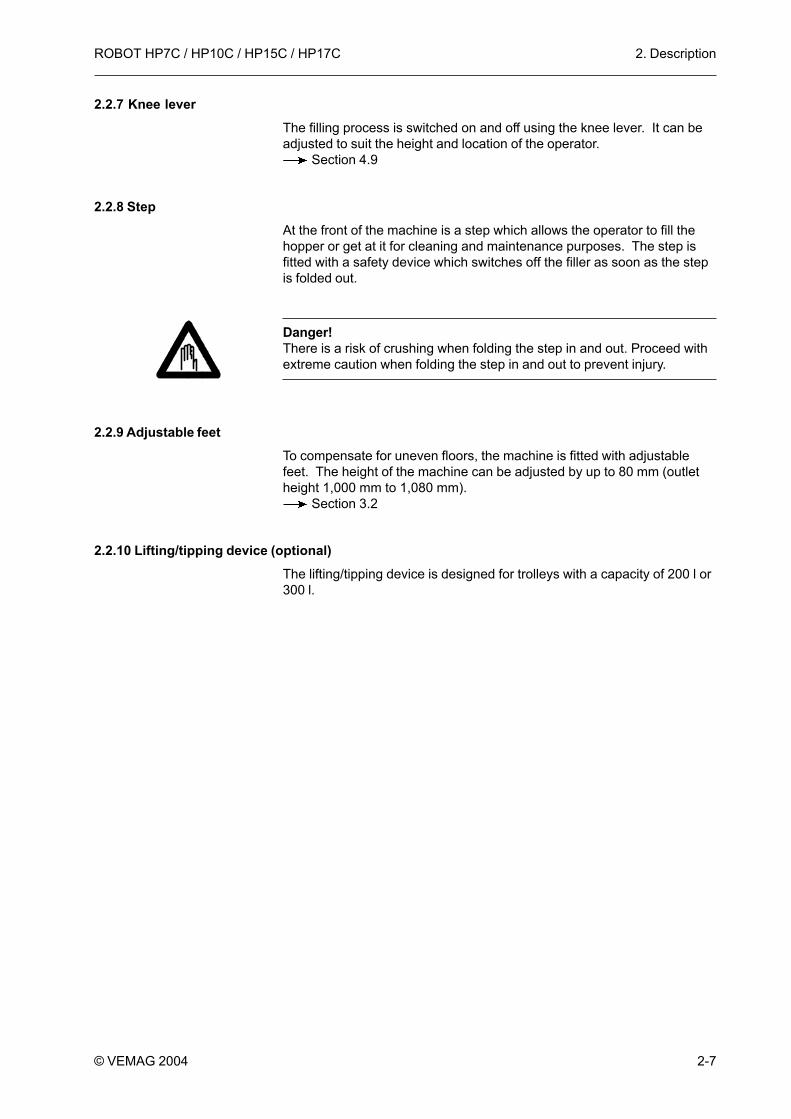
2.2.8 StepAt the front of the machine is a step which allows the operator to fill thehopper or get at it for cleaning and maintenance purposes. The step isfitted with a safety device which switches off the filler as soon as the stepis folded out.
Danger!There is a risk of crushing when folding the step in and out. Proceed withextreme caution when folding the step in and out to prevent injury.
2.2.9 Adjustable feetTo compensate for uneven floors, the machine is fitted with adjustablefeet. The height of the machine can be adjusted by up to 80 mm (outletheight 1,000 mm to 1,080 mm).
Section 3.2
2.2.10 Lifting/tipping device (optional)The lifting/tipping device is designed for trolleys with a capacity of 200 l or300 l.

2. Description ROBOT HP7C / HP10C / HP15C / HP17C
2-8 © VEMAG 2004

3. Installation and commissioningROBOT HP7C / HP10C / HP15C / HP17C
3-1© VEMAG 2004
3. Installation and commissioning3.1 Transporting the machine
The machine may only be transported using suitable lifting trucks or fork-lift trucks with a capacity of at least 1,500 kg. If at all possible, move thefork-lift/lifting truck under the machine from the outlet side.
Danger!Never tilt the machine when transporting it and when setting it up, alwayskeep it horizontal. This prevents the machine tipping over. Whentransporting the machine, it is essential to observe its centre of gravity.
Fig. 3-1Centre of gravity of themachine
960
410
Fig. 3-2Centre of gravity of themachine
960
410

3. Installation and commissioning ROBOT HP7C / HP10C / HP15C / HP17C
3-2 © VEMAG 2004
• Drive the lifting truck / fork-lift truck in under the machine so that fork(1) is located precisely centrally between the feet.
Warning!Place planks (2) between the fork and the machine to prevent themachine slipping during transportation. You must ensure that the fork andthe planks are pushed right under the machine so that the connectioncable and the fan in the base-plate are not damaged by the fork.
1 Fork2 Plank
Fig. 3-3Transporting the machine12

3. Installation and commissioningROBOT HP7C / HP10C / HP15C / HP17C
3-3© VEMAG 2004
3.2 Setting up the machineThe machine must stand firmly on all four feet at all times and be as levelas possible. There may only be a slight inclination (max. 2°) in thedirection of the outlet side to encourage water to drain off after cleaning.The feet (1) can be adjusted using universal spanner (2). If necessary, theadjustable feet must be used to compensate for any unevenness in thefloor until the machine is absolutely level.
The outlet height of the machine is 1,000 mm as standard. It can beincreased by up to 80 mm with the aid of the adjustable feet.
• Unscrew feet: height of outlet is increased
• Screw in feet: height of outlet is decreased
1 Adjustable foot2 Universal spanner
Fig. 3-4Setting up the machine
1
2

3. Installation and commissioning ROBOT HP7C / HP10C / HP15C / HP17C
3-4 © VEMAG 2004
3.3 Electrical connection
Danger!To prevent injury (electric shock), the electrical connection may be madeonly by authorised specialist staff or specialist companies.
• Inside the machine housing, connect the machine to the main switch(1) of the machine using four-core cable with 3 x phase and 1 x earthwire. There is a cable conduit in the base-plate. For correct connectionvalues
Section 9
1 Main switch
Fig. 3-5Electrical connection
1

3. Installation and commissioningROBOT HP7C / HP10C / HP15C / HP17C
3-5© VEMAG 2004
3.4 Checking direction of rotation
Warning!To avoid damage to the machine, the machine may not be operated formore than 10 seconds in the wrong direction of rotation.
This is why it is essential to check whether the individual phases of thealternating current supply have been connected according to specificationafter the machine has been electrically connected; if the phases havebeen switched, the motors start up in the wrong direction of rotation.
To check the direction of rotation, proceed as follows:
• Remove vacuum pot.
• Take hold of the float valve on valve body (1) and pull it horizontally offthe vacuum line.
Warning!Do not take hold of the float valve at the bottom at the screen to avoidtilting when pulling off the valve.
• Switch on the machine and check whether air is being drawn in by thevacuum line. If air is being drawn in, the motors are running in thecorrect direction of rotation. If no air is drawn in, the motors are runningin the incorrect direction of rotation.
• In this case, stop the machine immediately and have the alternatingcurrent supply connected in correct phase by authorised specialiststaff or a specialist company.
• Repeat the check on direction of rotation if appropriate.
• Put the float valve back on the vacuum line.
• Put the vacuum pot back on.
1 Valve body
Fig. 3-6Float valve
1

3. Installation and commissioning ROBOT HP7C / HP10C / HP15C / HP17C
3-6 © VEMAG 2004
3.5 Levelling the lifting/tipping device (optional)The trolley hoist of the lifting/tipping device is set at the factory with thefeet of the machine screwed in and on a level floor (outlet height 1,000mm). If the feet of the machine are screwed out to adjust height or levelthe machine in the horizontal plane, the stop parts on the lifting/tippingdevice will have to be reset to obtain the correct height for the trolley.
Adjust the lifting/tipping device as follows:
• Make the machine absolutely level using the adjustable feet. Section 3.2
• Undo the four mounting bolts (1) for the stop bar (2) of the trolley hoistand push the bar right in.
• Switch on the machine and move the arm of the lifting/tipping device tothe vertical end position using the UP key.
1
2
1 Mounting bolts2 Stop bar
Fig. 3-7Stop

3. Installation and commissioningROBOT HP7C / HP10C / HP15C / HP17C
3-7© VEMAG 2004
• Undo the two top mounting bolts (1) on the back of drive hood (2) andtap the bolts to release the drive hood. Push the hood and its seal inthe direction of the operator side until the pins (3) release the guidegrooves and lift it off.
• Undo the mounting screws (1) of switch (2) and put it down on themachine housing.
• Undo the guard ring (3) with the face spanner (4).
• Use the setting ring (5) to set the desired angle of rotation. One turn ofthe setting ring adjusts the angle of rotation by 2.7°. This correspondsto an adjustment in the height of the trolley hoist of approx. 50 mm.The gap between the floor and the edge of the trolley guide on thetrolley hoist needs to be approx. 237 mm.
Turn clockwise: trolley hoist moves up
Turn anti-clockwise: trolley hoist moves down
1 Mounting bolts2 Drive hood3 Pins
Fig. 3-8Drive hood
1 2
3
1 Mounting screws2 Switch3 Guard ring4 Face spanner5 Setting ring
Fig. 3-9Setting trolley hoist12
4
35

3. Installation and commissioning ROBOT HP7C / HP10C / HP15C / HP17C
3-8 © VEMAG 2004
• Move the arm of the lifting/tipping device into the bottom end positionusing the DOWN key. Push a trolley into the trolley hoist to check thecorrect height of the trolley hoist and repeat setting if necessary.
• If the trolley hoist is set to the right height, lock the setting ring againwith the guard ring. Attach the switch again.
• Lightly grease the contact surfaces of the seals of the drive hood andput the hood back on. Then tighten up the mounting bolts again.
• The trolley hoist (1) must be absolutely level to ensure that the trolleymoves in and is locked in position securely. To do so, undo the guardnut (2) with the universal spanner and adjust stop screw (3).
• Screw in screw: locking lever of trolley hoist moves down
• Screw out screw: locking lever of trolley hoist moves up
2
3
1
1 Trolley hoist2 Guard nut3 Stop screw
Fig. 3-10Levelling the trolley hoist

3. Installation and commissioningROBOT HP7C / HP10C / HP15C / HP17C
3-9© VEMAG 2004
• Check that the trolley hoist is level using a spirit level, and push atrolley right into the trolley hoist.
Warning!Check whether the locking lever (1) is properly locked and is holding thetrolley securely in the trolley hoist.
• Then lock the stop screw with the guard nut again.
• If the trolley hoist (1) is correctly level, pull the stop bar (2) out farenough for the gap between the bar and the trolley hoist to be 5 mmand tighten up the four mounting bolts (3) again.
1
1 Locking lever
Fig. 3-11Locking the trolley inposition
3
2
1 Trolley hoist2 Stop bar3 Mounting bolts
Fig. 3-12Setting the stop
1

3. Installation and commissioning ROBOT HP7C / HP10C / HP15C / HP17C
3-10 © VEMAG 2004

4. Setting upROBOT HP7C / HP10C / HP15C / HP17C
4-1© VEMAG 2004
4. Setting up4.1 General information
• To set up the machine, select a double screw housing, the doublescrews to suit the product to be processed and the requiredaccessories.
Danger!To prevent injury, switch off the machine before setting up. Then switch offthe main switch to disconnect the machine from the mains.
4.2 Fitting the double screw housing
Danger!There is a risk of crushing when fitting and removing the double screwhousing and the double screws. To prevent injury, proceed extremelycarefully when fitting and dismantling these parts.
The machine is fitted with an all-in-one or a two-part double screwhousing.
• All-in-one double screw housing:push double screw housing (1) right into the feed cylinder of themachine. Inlet bore (2) for product and vacuum should face upwards.
• Two-part double screw housing:first push the rear, longer part of the housing with the inlet bore forproduct and vacuum upwards right into the feed cylinder of themachine. Then push the front, shorter part of the housing into the feedcylinder up to the stop.
2
1
1 Double screw housing2 Inlet bore
Fig. 4-1Installing double screwhousing

4. Setting up ROBOT HP7C / HP10C / HP15C / HP17C
4-2 © VEMAG 2004
A pin (1) under the coupling pins (2) in the feed cylinder centres thedouble screw housing which has the appropriate bore on its end face.The rear part of the housing of the two-part double screw housing likewisehas a centring pin for centring the front part of the housing.
• To prevent air bubbles in the product, the air relief bores of the doublescrew housing should be adjusted to suit the product using the settingscrews (1). The air relief bores are closed when the screw slots arehorizontal. If the screw slots are vertical with the screws tightened rightup, the air relief bores are open.
• The product weight set should be compared with the weight actuallyfilled at the start of production.
1
1 Centring pin2 Coupling pins
Fig. 4-2Centring the double screwhousing
2
1 1 Setting screws
Fig. 4-3Setting the air relief bores

4. Setting upROBOT HP7C / HP10C / HP15C / HP17C
4-3© VEMAG 2004
4.3 Fitting the double screws• Position the double screws (1) so that the screw marked left (”links”) is
on the left-hand side and the front faces are flush.
• Bring the slots of coupling claws (2) into the correct position in relationto the coupling pins in the feed cylinder by turning the double screws inopposite directions.
• Push double screws (1) into double screw housing (2) up to the stop.The double screws are properly engaged if the end faces of the doublescrews and housing are flush.
1 2
1 Double screws2 Slots
Fig. 4-4Lining up the doublescrews
1
1 Double screws2 Double screw housing
Fig. 4-5Installation of doublescrews
2

4. Setting up ROBOT HP7C / HP10C / HP15C / HP17C
4-4 © VEMAG 2004
4.4 Fitting the filling horn• Adjust locking nut (1) so that the handle is between the 10 and
11 o’clock position and insert filling horn holder (2).
• Turn locknut (1) clockwise to lock the filling horn holder. The handleshould now be approximately vertical.
• Select a filling horn with the largest possible diameter related to thesize of the casing.
• Use the filling horn nut (2) on the filling horn holder (3) to attach thefilling horn (1). Use the appropriate universal spanner (4).
1
2
1 Locking nut2 Filling horn holder
Fig. 4-6Locking the filling hornholder
31
2
1 Filling horn2 Filling horn nut3 Filling horn holder4 Universal spanner
Fig. 4-7Fitting the filling horn
4

4. Setting upROBOT HP7C / HP10C / HP15C / HP17C
4-5© VEMAG 2004
4.5 Locking the linking gear (optional)
Danger!There is a risk of crushing when swivelling the linking gear in and out. Toprevent injury, proceed extremely carefully when fitting and dismantlingthe part.
• Attach linking gear (1) to the outlet side of the machine with the aid ofthe two bearing journals (2).
• Adjust locking nut (1) so that the handle is between the 10 and11 o’clock position and swing linking gear (2) in front of the outlet.
• Turn the locking nut clockwise to lock the linking gear. The handleshould now be approximately vertical.
1
1 Linking gear2 Bearing journals
Fig. 4-8Fitting the linking gear(optional)
2
1 Locking nut2 Linking gear
Fig. 4-9Locking the linking gear(optional)
21

4. Setting up ROBOT HP7C / HP10C / HP15C / HP17C
4-6 © VEMAG 2004
4.6 Fitting the linking horn (optional)• Use a linking horn with the largest possible diameter and shortest
possible length related to the size of the casing.
• Fit lip seal (1) in linking horn (2) so that the lug of the lip seal is pointingforwards.
• Grease the seal of the linking horn before fitting it to prevent frictionproblems.
1 Lip seal2 Linking horn
Fig. 4-10Fitting the lip seal
12
Fig. 4-11Greasing the linking horn

4. Setting upROBOT HP7C / HP10C / HP15C / HP17C
4-7© VEMAG 2004
1 Linking horn2 Linking head3 Linking nut4 Universal spanner
Fig. 4-12Fitting the linking horn32 1
4
• Insert linking horn (1) into linking head (2) and tighten linking nut (3)using universal spanner (4). Hold the linking head steady with thesecond universal spanner as you do so.
Warning!The linking head has a left-hand thread.• To tighten: turn anti-clockwise• To loosen: turn clockwise
Warning!When processing very fine product (e.g. cooked sausage meat) a fillercone can be inserted in the linking gear to optimise the particle definitionof the end-product.
Linking gear spare parts catalogue

4. Setting up ROBOT HP7C / HP10C / HP15C / HP17C
4-8 © VEMAG 2004
4.7 Setting the vacuum4.7.1 Filling raw and cooked sausage
• Set the maximum vacuum for filling raw and cooked sausage.
4.7.2 Filling liquid product (e.g. liver sausage)• Put blind plug (1) together with O-ring (2) and retaining ring (3) in the
rear opening of double screw housing (4).
Warning!Before processing any liquid product, check whether the blind plug islocated in the double screw housing. If the blind plug is not present, thevacuum pump may be destroyed. If the vacuum pump takes in product orwater as a consequence of a missing or incorrectly fitted blind plug, it isessential to proceed as follows to prevent damage to or destruction of thevacuum pump:• Stop the machine immediately.• Clean the air filter in the intake line• Change the oil in the vacuum pump.
Section 7
1 Blind plug2 O-ring3 Retaining ring4 Double screw housing
Fig. 4-13Double screw housing
1
4
2
3

4. Setting upROBOT HP7C / HP10C / HP15C / HP17C
4-9© VEMAG 2004
4.8 Fitting the scraperA scraper can be fitted to the hopper for product which sticks to the wall ofthe hopper. The scraper must be used when processing raw sausage.
Danger!There is a risk of crushing when fitting and removing the scraper. Toprevent injury, proceed extremely carefully when fitting and dismantlingthe part.
• Put the scraper (1) on the locking pin (2) of the feed screw and makesure it engages.
2
1 1 Scraper2 Locking pin
Fig. 4-14Fitting the scraper

4. Setting up ROBOT HP7C / HP10C / HP15C / HP17C
4-10 © VEMAG 2004
4.9 Adjusting the knee leverThe knee lever can be adjusted in terms of height (H), angle (W) andprojection (A) to suit the height and location of the operator.
• Undo the hexagonal nut (1) using the universal spanner (2).
• Adjust the knee lever to the desired height (H) and angle (W).
• Tighten up the hexagonal nut again.
• Move the knee lever plate (3) along the lever shaft until the desiredprojection (A) is reached. The plate can be taken off the lever shaftaltogether if required.
H1
1 Hexagonal nut2 Universal spanner3 Knee lever plate
Fig. 4-15Adjusting the knee lever
W
A
3
2

5. OperationROBOT HP7C / HP10C / HP15C / HP17C
5-1© VEMAG 2004
5. Operation5.1 Working with the machine
To start production with the machine, proceed as follows:
• Set up the machine for the product to be filled Section 4
• Switch on the main switch of the machine.
• Press the ON switch on the machine control panel.
Danger!You must check that any safety devices fitted to the hopper and the stepare working properly.• Unlock the hopper and tip it open.• Fold out the step.• Remove the filling horn holder.In each of the cases described, the machine must switch off automatically.If the machine does not switch off, work may not continue with themachine. In this case, inform VEMAG Customer Service immediately.
• Pull on a casing suitable for the product to be filled.
• Push the trolley containing product into the trolley hoist of the lifting/tipping device up to the stop. The locking lever must lock and hold thetrolley securely in the trolley hoist.
• Press the UP key of the lifting/tipping device to move the trolley overthe hopper with the trolley hoist. The trolley is automatically emptiedinto the hopper.
Danger!Make sure that there is no-one in the area of the lifting/tipping deviceduring operation and that no objects have been deposited there.
• Press the DOWN key to lower the trolley again. The trolley hoist staysapprox. 500 mm above the floor. Press the DOWN key again and keepit depressed until the trolley has reached the floor.

5. Operation ROBOT HP7C / HP10C / HP15C / HP17C
5-2 © VEMAG 2004
• Unlock the locking lever (1) with your foot and pull the trolley out of thetrolley hoist.
1 Locking lever
Fig. 5-1Trolley
1

5. OperationROBOT HP7C / HP10C / HP15C / HP17C
5-3© VEMAG 2004
• If you want to use the machine to link, test the relevant linking horn forconcentricity with the aid of the respective program.
Portioning computer user guide
• Use the portioning computer to select a filling program and checkwhether the double screws are correctly selected in the portioningcomputer.
Portioning computer user guide
• Set the vacuum required for the product to be filled at the vacuumreducing valve. Put the blind plug in the double screw housing ifnecessary.
Section 4
Warning!You must interrupt the filling process and check the seals of the doublescrew drive if vacuum level falls uncontrollably during production.
Sections 6 and 7
• At the start, allow the machine to run at a slow speed (max. 20 %) untilproduct escapes at the outlet.
This prevents the pumping element “running dry”. When filling hotproducts, wait about 1 minute to start production. This ensures that allmachine parts which come into contact with the product are heated toproduct temperature.
• Operate the knee lever to start the filling process.
When production is finished, proceed as follows:
• Press the OFF key on the machine control panel.
• Switch off the main switch of the machine.
• Clean the machine in accordance with the instructions in the cleaningschedule.
Section 6
• Take the appropriate maintenance measures if necessary. Section 7

5. Operation ROBOT HP7C / HP10C / HP15C / HP17C
5-4 © VEMAG 2004
5.2 Working with provisional driveShould the portioning computer of the machine fail, it is possible tocontinue operating the machine using provisional drive.
• Press the OFF key on the machine control panel.
• Switch off the main switch of the machine.
• Pull the trolley out of the trolley hoist of the lifting/tipping device anddismantle the right-hand machine cover.
• Switch on the provisional drive switch on the rear of the electricalcontrol panel (rocker switch).
• Re-fit the right-hand machine cover.
• Switch the main switch of the machine back on.
• Press the ON key on the machine control panel.
• Press the knee leverThe message ”PROVISIONAL DRIVE” appears in the display of theportioning computer. In this mode, you can straight-fill at approximately50% of nominal speed or run the hopper empty.
• Inform VEMAG Customer Service.

6. CleaningROBOT HP7C / HP10C / HP15C / HP17C
6-1© VEMAG 2004
6. Cleaning6.1 General information
The machine and any attachments and additional devices (optional) mustbe cleaned daily.
Danger!To prevent injury, take the following measures before cleaning.
• Press the OFF key on the machine control panel.
• Switch off the main switch of the machine to disconnect it from themains.
• Disconnect any attachments or additional devices (optional) from themains and remove the devices.
Attachment operating instructions
Danger!The linking gear can heat up at extremely high speeds (risk of burns). Toprevent injury, proceed extremely carefully when fitting and dismantlingthe part.
6.2 Removing parts to be cleaned6.2.1 Filling horn and filling horn holder
• Undo filling horn nut (1) and remove filling horn (2). To do so, useuniversal spanner (3).
• Undo the locking nut with the handle anticlockwise until the bayonetlugs come free and remove the filling horn holder.
312
1 Filling horn nut2 Filling horn3 Universal spanner
Fig. 6-1Removing filling horn

6. Cleaning ROBOT HP7C / HP10C / HP15C / HP17C
6-2 © VEMAG 2004
6.2.2 Linking horn (optional)• Undo linking nut (1) with the universal spanner (2) and remove linking
horn (3). Hold the linking head steady with the second universalspanner as you do so.
Warning!The linking head has a left-hand thread.• To tighten up: turn anti-clockwise.• To undo: turn clockwise.
6.2.3 Linking gear (optional)• Undo locking nut (1) with the handle anticlockwise until the bayonet
lugs (2) come free.
• Swing linking gear (3) to the side.
• Remove filler cone (4) from the linking gear if present. To do so, usethe appropriate ejector.
• Lift the linking gear off the bearing journals (5) on the machinehousing.
2
1
1 Locking nut2 Bayonet lugs3 Linking gear4 Filler cone5 Bearing journals
Fig. 6-3Removing the linking gear(optional)
5
4
3
1 Linking nut2 Universal spanner3 Linking horn
Fig. 6-2Removing the linking horn(optional)
13
2
6. CleaningROBOT HP7C / HP10C / HP15C / HP17C
6-3© VEMAG 2004
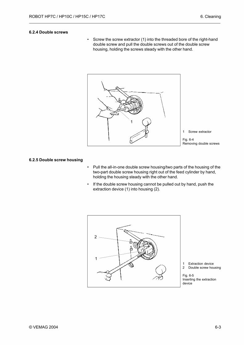
6.2.4 Double screws• Screw the screw extractor (1) into the threaded bore of the right-hand
double screw and pull the double screws out of the double screwhousing, holding the screws steady with the other hand.
6.2.5 Double screw housing• Pull the all-in-one double screw housing/two parts of the housing of the
two-part double screw housing right out of the feed cylinder by hand,holding the housing steady with the other hand.
• If the double screw housing cannot be pulled out by hand, push theextraction device (1) into housing (2).
1 Screw extractor
Fig. 6-4Removing double screws
1
1 Extraction device2 Double screw housing
Fig. 6-5Inserting the extractiondevice
1
2
6. Cleaning ROBOT HP7C / HP10C / HP15C / HP17C
6-4 © VEMAG 2004
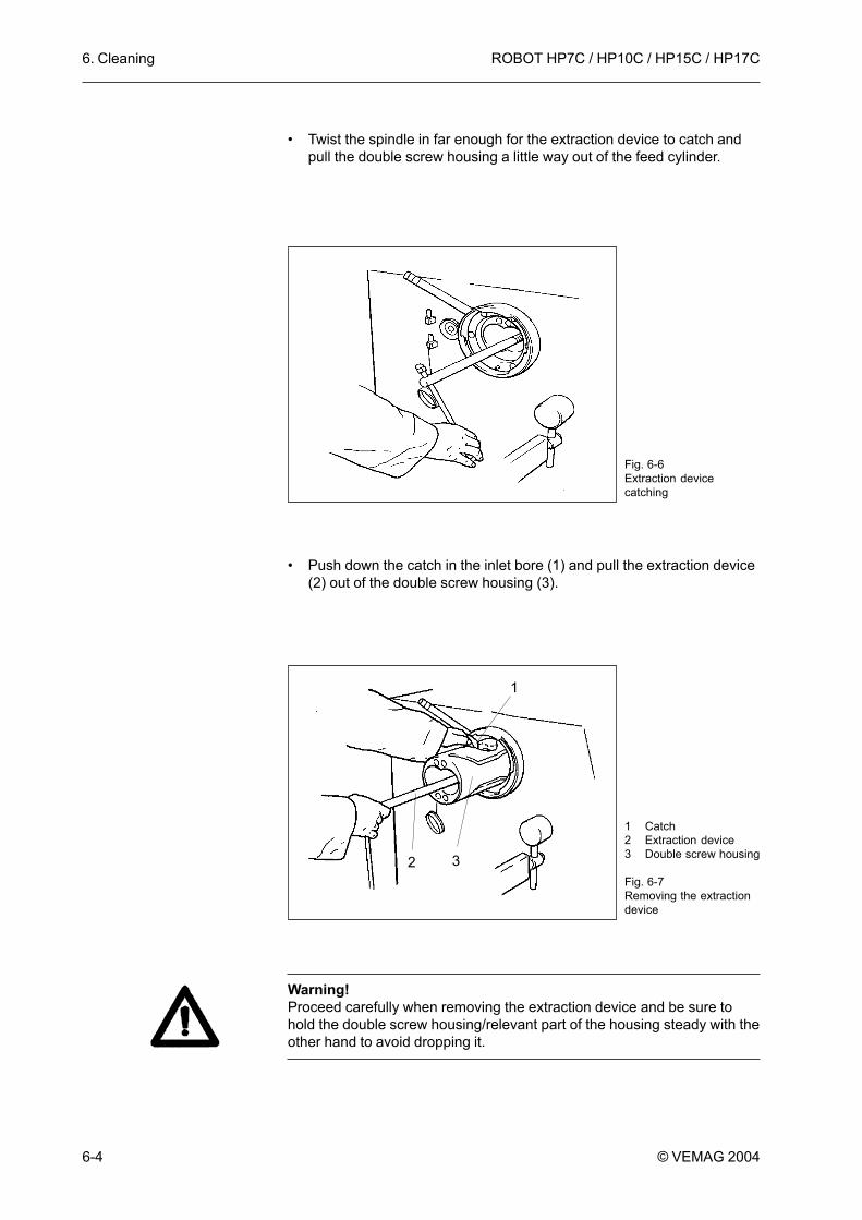
• Twist the spindle in far enough for the extraction device to catch andpull the double screw housing a little way out of the feed cylinder.
• Push down the catch in the inlet bore (1) and pull the extraction device(2) out of the double screw housing (3).
Warning!Proceed carefully when removing the extraction device and be sure tohold the double screw housing/relevant part of the housing steady with theother hand to avoid dropping it.
Fig. 6-6Extraction devicecatching
1 Catch2 Extraction device3 Double screw housing
Fig. 6-7Removing the extractiondevice
1
32

6. CleaningROBOT HP7C / HP10C / HP15C / HP17C
6-5© VEMAG 2004
• Pull the double screw housing/relevant part of the housing right out ofthe feed cylinder by hand, holding the housing steady with the otherhand.
• Then check the rear seal in the feed cylinder for traces of oil.
Warning!You must check the seals of the double screw drive for traces of oil beforecleaning. If traces of oil are present, the double screw drive must beoverhauled or replaced. In this case inform VEMAG Customer Service.
Fig. 6-8Removing the doublescrew housing

6. Cleaning ROBOT HP7C / HP10C / HP15C / HP17C
6-6 © VEMAG 2004
6.2.6 Hopper
Danger!There is a risk of crushing when fitting/removing the feed screw. Toprevent injury, proceed extremely carefully when fitting and dismantlingthe part.
• Unlock the two locking levers (1) on the hopper housing and carefullytip the hopper backwards. Hold the hopper firmly by flange (2) as youdo so.
• Remove the scraper in the hopper (if present).
• Push back the three sliding sleeves (3) in the hopper flange, holdingthe feed screw (4) steady with the other hand. Carefully twist the feedscrew out of the hopper flange.
• Remove the sealing ring (1) from the hopper flange (2). Use theappropriate tool at the cleaning plug (3) to do this.
1 Locking levers2 Flange3 Sliding sleeves4 Feed screw
Fig. 6-9Hopper
2
3
11
4
1 Sealing ring2 Hopper flange3 Cleaning plug
Fig. 6-10Feed unit seal
2
3
1
6. CleaningROBOT HP7C / HP10C / HP15C / HP17C
6-7© VEMAG 2004
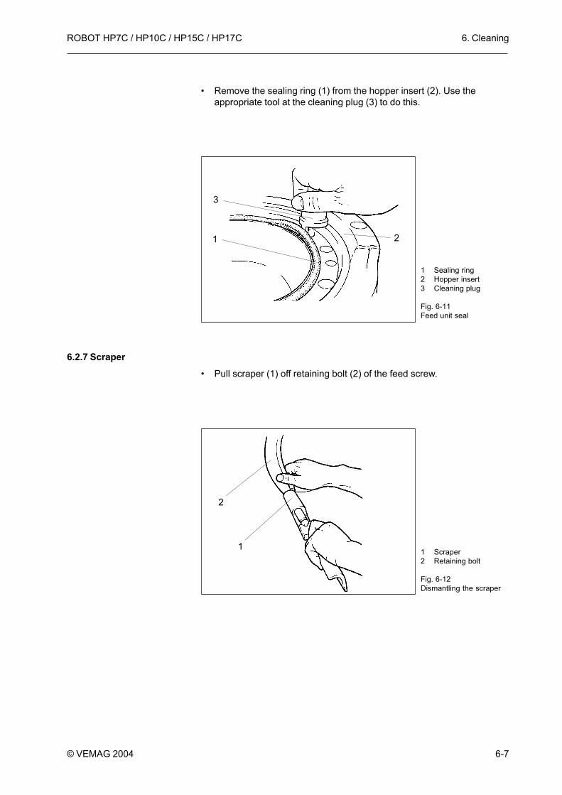
• Remove the sealing ring (1) from the hopper insert (2). Use theappropriate tool at the cleaning plug (3) to do this.
6.2.7 Scraper• Pull scraper (1) off retaining bolt (2) of the feed screw.
1 Sealing ring2 Hopper insert3 Cleaning plug
Fig. 6-11Feed unit seal
2
3
1
2
1 1 Scraper2 Retaining bolt
Fig. 6-12Dismantling the scraper

6. Cleaning ROBOT HP7C / HP10C / HP15C / HP17C
6-8 © VEMAG 2004
6.2.8 Vacuum system• Remove the vacuum pot.
• Take hold of the float valve on the valve body (1) and pull it off theintake pipe of the vacuum line in a horizontal direction.
Warning!Do not take hold of the float valve at the bottom on the screen whenpulling it off to avoid it tilting.
• Then pull the screen (1) off valve body (2).
1 Valve body
Fig. 6-13Float valve
1
1
2
1 Screen2 Valve body
Fig. 6-14Float valve

6. CleaningROBOT HP7C / HP10C / HP15C / HP17C
6-9© VEMAG 2004
Warning!Before cleaning, you must plug the cleaning plug onto the intake pipe ofthe vacuum line to protect the vacuum pump.
The cleaning plug (1) is located on the front of the machine.
1 Cleaning plug
Fig. 6-15Cleaning plug
1

6. Cleaning ROBOT HP7C / HP10C / HP15C / HP17C
6-10 © VEMAG 2004
6.3 Cleaning the machineClean the machine housing, the hopper, the feed screw, the linking gear(optional) and all the parts which have been removed thoroughly with hotwater and a brush and then dry them. The machine is suitable for cleaningwith low-pressure cleaning equipment (max. 25 bar).
Warning!Never aim the jet of water directly at the double screw drive, the sealingelements and the machine control panel when using low-pressurecleaning equipment and keep the nozzle at the distance from the surfaceof the machine specified for the cleaning equipment.
In addition to the instructions in the cleaning schedule, generally-applicable and product-specific hygiene regulations should be followed.
When cleaning the double screws, pay particular attention to the jointsbetween the screw and the coupling claw (1).
11 Joint
Fig. 6-16Double screws

6. CleaningROBOT HP7C / HP10C / HP15C / HP17C
6-11© VEMAG 2004
Cleaning agent
water
free of activated chlorine,alkaline, concentrationdepending on degree ofcontamination – as low aspossible – and in accordancewith manufacturer’sinstructions
free of activated chlorine,acid, concentration dependingon degree of contamination –as low as possible – and inaccordance withmanufacturer’s instructions
drinking water
disinfectant free of activatedchlorine, concentration as lowas possible and in accordancewith the manufacturer’sinstructions
drinking water
oil which is safe for food use
Process
• by hand,mechanically
• water jet max. 25bar, temperaturemax. 60 °C,depending on fatsoftening point
• visual
• foam or clean byhand, leave to actfor approx. 15minutes
• foam or clean byhand, leave to actfor approx. 15minutes
• water jet max. 25bar, temperature50 to 60 °C
• visual
• spray, foam, leaveto act inaccordance withmanufacturer’sinstructions
• water jet max. 25bar
• spray
Notes
Begin as soonas productionfinishes
Clean smallparts at thesame time
Carry outdaily, cleansmall parts atthe same time
Frequency asrequired
Wholemachine andsmall parts
Pay specialattention tofeed system,small parts
Whole systemand smallparts
Rinse off inaccordancewith MeatHygieneOrder,Appendix 2, II,4
Particularlyfeed system
Equipment
plastic spatula,scraper(Schlesinger)
low-pressureequipment, hose
low-pressure foamequipment (max. 25bar), hand spray,brush, bowl
low-pressure foamequipment (max. 25bar), hand spray,brush, bowl
low-pressureequipment (max. 25bar), hose
low pressureequipment (max. 25bar), hand spray
low-pressureequipment (max. 25bar), hose
hand spray
Cleaning task
Rough cleaning,removal of productresidues (ifnecessary, removesmall parts first)
Thorough initialrinse
Visual check ofcleanliness
Alkaline cleaning
or:
Acid cleaning toremove limedeposits
Rinse
Visual check ofcleanliness
Disinfect (after allthe cleaningmeasures in theroom have beencompleted)
Rinse off
Dry and oil
6.4 Cleaning scheduleAll details refer to single-shift operation.
6. Cleaning ROBOT HP7C / HP10C / HP15C / HP17C
6-12 © VEMAG 2004
6.5 Lubrication and assembly• Thoroughly lubricate all dismantled, cleaned and dried parts (apart
from vacuum system parts) with a corrosion-inhibiting oil which is safefor food use.
Section 9
• Refit the dismantled parts after cleaning and lubrication.
Warning!Parts which have been removed should be left overnight and not re-fitteduntil the shift starts the next morning.
6.5.1 Hopper• Carefully press the sealing rings into the appropriate grooves in the
hopper flange and hopper insert. Fit the sealing rings without greasingthem.
Section 6.2.6
• Lubricate the sealing rings and the sliding ring in the hopper flange byhand before the feed screw is fitted. Use a grease for this which hasbeen approved for contact with foodstuffs.
Sections 7 and 9
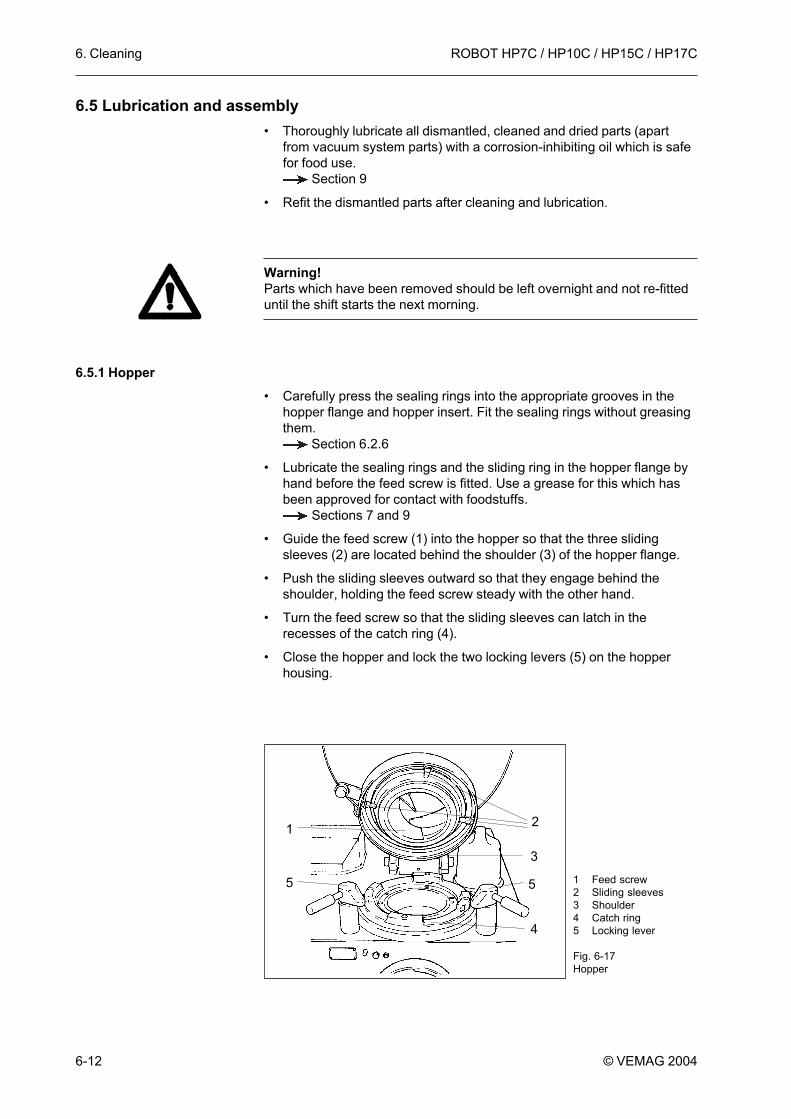
• Guide the feed screw (1) into the hopper so that the three slidingsleeves (2) are located behind the shoulder (3) of the hopper flange.
• Push the sliding sleeves outward so that they engage behind theshoulder, holding the feed screw steady with the other hand.
• Turn the feed screw so that the sliding sleeves can latch in therecesses of the catch ring (4).
• Close the hopper and lock the two locking levers (5) on the hopperhousing.
1 Feed screw2 Sliding sleeves3 Shoulder4 Catch ring5 Locking lever
Fig. 6-17Hopper
4
2
55
1
3

7. Maintenance
7-1
ROBOT HP7C / HP10C / HP15C / HP17C
© VEMAG 2004
7. Maintenance7.1 General information
Apart from daily cleaning, the filler needs very little maintenance. For yourpeace of mind, we recommend that you take out a service contractwhereby VEMAG Customer Service carries out all the maintenance workdue.
The information below describes the maintenance work to be performedby the owner of the machine. The types and quantities of lubricantsrequired are listed in the appendix. Notes on spare parts required can befound in the spare parts catalogue.
Section 9 and spare parts catalogue
Danger!To prevent injury, switch off the machine before any maintenance work.Then switch off the main switch to disconnect the machine from themains. The machine has to be switched on for the feed unit drive to belubricated.
The relevant cover of the machine housing has to be removed to allowinternal components of the drive system to be serviced.
• Undo the appropriate assembly screws with a screwdriver.
• Remove housing cover
• Carry out the necessary maintenance work according to themaintenance schedule.
Section 7.4
• Clean the contact surfaces of the cover seals and lubricate lightlybefore re-fitting.
• Put housing cover back on.
Regularly check the hydraulic system of the machine, including all pipeand hose lines, for damage or leaks. Inform VEMAG Customer Service ifyou find damage or leaks.
Warning!DIN 20066 states that the service life of hose lines should not exceed sixyears. For this reason, you should have the hose lines of the hydraulicsystem checked by VEMAG Customer Service after six years to avoidleaks.
Warning!Used oil and other substances should be disposed of in accordance withthe relevant environmental protection regulations in force.

7. Maintenance
7-2
ROBOT HP7C / HP10C / HP15C / HP17C
© VEMAG 2004
7.2 Grease gunThe cartridges for the grease gun supplied are replaced as follows:
• Pull piston rod (1) back firmly to the stop.
• Unscrew the head of the grease gun (2) and pull out the emptycartridge.
• Remove the cap of the new cartridge and insert fully into the greasegun with this open end first.
• Either cut off the base of the cartridge (3) completely with a knife orpierce a hole in it.
• Screw the head of the grease gun back on and push the piston rodback in, pressing down the small retaining lug (4).
• If no grease emerges after a number of pump strokes, vent the greasegun by pressing the relief knob (5) whilst pumping.
7.3 First-time maintenance workPerform the following maintenance work for the first time after theintervals given. After that, these measures should be effected inaccordance with the maintenance schedule.
Section 7.4
after 500 operating hours: change hydraulic oil and filter cartridge ofhydraulic drive
after 1000 operating hours: change transmission oil of double screwdrive.
1
24
5
3
1 Piston rod2 Head3 Cartridge4 Retaining lug5 Relief knob
Fig. 7-1Grease gun

7. Maintenance
7-3
ROBOT HP7C / HP10C / HP15C / HP17C
© VEMAG 2004
Maintenanceinterval
daily
weekly
monthly
quarterly
six-monthly
annually
biennially
Operatinghours
8
20
40
160
160
500
1000
2000
2000
2000
4000
Machine part
Feed unit seals
Feed unit drive
Vacuum pump
Hydraulic drive
Double screw drive
Vacuum pump
Feed unit seals
Hydraulic drive
Feed unit drive and feed unitseals
Vacuum pump
Double screw drive
7.4 Maintenance scheduleAll information relates to single-shift operation. The portioning computershows the number of operating hours reached in each case. All themaintenance tasks included under one operating hours heading should beperformed. In the case of monthly maintenance (160 hours), it follows thatall daily and weekly maintenance work due should also be performed.
The jobs listed in the maintenance schedule are described in detail in thefollowing sections.
Maintenance work
• Lubricate sliding ring and seals by handevery time they are cleaned. Use only high-performance grease which is safe for fooduse.
• Lubricate drive and bearing 2x a week withthe feed unit running slowly. Use only high-performance grease which is safe for fooduse and resistant to cleaning agents anddisinfectants.
• Check air filter in the intake line to thevacuum pump for contamination. Cleanfilter cartridge of air filter or replace ifseverely contaminated.
• Check oil level.
• Check oil level.
• Check oil level.• Check seals.
• Change oil.• Clean screens of vacuum pump.• Clean gas ballast valve (only if pump
housing very dirty).
• Have seals checked by VEMAG CustomerService.
• Change oil and replace filter cartridge.
• Have parts checked by VEMAG CustomerService and have feed unit seals changed.
• Replace air de-oiling element.
• Change oil.

7. Maintenance
7-4
ROBOT HP7C / HP10C / HP15C / HP17C
© VEMAG 2004
7.5 Daily maintenance7.5.1 Feed unit seals (lubrication)
The feed unit seals must be lubricated daily every time they are cleaned.Use only high-performance grease which is safe for food use.
• Carefully press the sealing ring into the appropriate groove in thehopper flange. Fit the sealing ring without greasing it.
Section 6.2.6
• Lubricate the sealing ring (1) and the sliding ring (2) in the hopperflange by hand before the feed screw is fitted.
1 Sealing ring2 Sliding ring
Fig. 7-2Lubricating the feed unitseals
2
1

7. Maintenance
7-5
ROBOT HP7C / HP10C / HP15C / HP17C
© VEMAG 2004
• Guide the feed screw (1) into the hopper in such a way that the threesliding sleeves (2) are located behind the shoulder (3) of the hopperflange.
• Push the sliding sleeves outwards so that they engage behind theshoulder, holding the feed screw steady with the other hand.
• Carefully press the sealing ring into the appropriate groove in thehopper insert. Fit the sealing ring without greasing it.
Section 6.2.6
• Lubricate the sealing ring (4) in the hopper insert by hand.
• Turn the feed screw so that the sliding sleeves can engage in therecesses of the catch ring (5).
• Close the hopper and lock the two locking levers (6) on the hopperhousing.
1 Feed screw2 Sliding sleeves3 Shoulder4 Sealing ring5 Catch ring6 Locking levers
Fig. 7-3Lubricating the feed unitseals
5
2
66
1
34

7. Maintenance
7-6
ROBOT HP7C / HP10C / HP15C / HP17C
© VEMAG 2004
7.6 Weekly maintenance7.6.1 Feed unit drive (lubrication)
The feed unit drive and the bearing must be lubricated twice a week withthe feed unit running slowly until grease escapes at the relief bore at theoutlet side of the machine. Use only high-performance grease which issafe for food use and which is resistant to cleaning agents anddisinfectants.
• To do so, connect the grease gun supplied to the left-hand lubricatingnipple (1) at the outlet side of the machine and pump several fullstrokes with the feed unit running until clean grease escapes fromrelief bore (2).
• Then remove the grease which has escaped.
• If no grease at all escapes at the relief bore, inform VEMAG CustomerService and have the drive/bearing checked.
1 Lubricating nipple2 Relief bore
Fig. 7-4Lubricating the feed unitdrive
1
2

7. Maintenance
7-7
ROBOT HP7C / HP10C / HP15C / HP17C
© VEMAG 2004
7.6.2 Vacuum pump (air filter and oil level)An air filter is located in the intake line to the vacuum pump and this needsto be cleaned weekly.
• Remove the housing cover next to the main switch on the rear of themachine.
• Open the two locking clips (1) of the air filter and remove the filtercover (2).
• Clean the filter cartridge (3) by blowing it out. If it is severelycontaminated, the filter cartridge must be replaced.
• Insert the filter cartridge and fix the filter cover in position.
1 Locking clips2 Filter cover3 Filter cartridge
Fig. 7-5Air filter of intake line
2
3
1

7. Maintenance
7-8
ROBOT HP7C / HP10C / HP15C / HP17C
© VEMAG 2004
The vacuum pump has a closed oil circuit. The oil reservoir is integral to thepump housing. There is a sight glass on each side of the pump forchecking the oil level. The oil should reach at least the centre of the sightglass.
Danger!To prevent injury (burns) do not carry out the following work with the pumpstill warm from operation, but wait until the pump has cooled down.
• Check the oil level of the vacuum pump in one of the sight glasses (1)on either side of the pump and, if required, replenish oil through thefilling opening (2).
• Re-fit the housing cover.
Replenish only with clean oil and clean the pump housing beforereplenishing to avoid contaminating the oil.
If the oil level in the sight glass is too high, water has accumulated in theoil reservoir. This can occur if the machine is operated for only briefperiods or water has entered the intake line during cleaning. In this case,change the oil.
Section 7.8.1
1 Sight glass2 Filling opening
Fig. 7-6Oil level of vacuum pump
1
2

7. Maintenance
7-9
ROBOT HP7C / HP10C / HP15C / HP17C
© VEMAG 2004
7.7 Monthly maintenance7.7.1 Hydraulic drive (oil level)
The tank is underneath the hydraulic drive. There is a sight glass forchecking oil level on the front of the tank. The oil should come at least tothe centre of the sight glass.
• Remove the housing cover over the stop bar for the trolley hoist on theright-hand side of the machine.
• Check the oil level of the hydraulic drive using the sight glass providedin the tank (1) and if necessary replenish oil through the filling opening(2).
• Re-fit the housing cover.
Considerable or continuous lack of oil indicates a leak which must beeliminated.
1 Sight glass2 Filling opening
Fig. 7-7Oil level of hydraulic drive
1
2

7. Maintenance
7-10
ROBOT HP7C / HP10C / HP15C / HP17C
© VEMAG 2004
7.7.2 Double screw drive (oil level and seals)The oil expansion reservoir of the double screw drive and its cover areattached in a bracket and connected to the double screw drive by a hose.The oil should come up at least to the marking on the reservoir.
• Remove the housing cover over the stop bar for the trolley hoist on theright-hand side of the machine.
• Undo the retaining screw and swivel out the electrical case (1).
• Check the oil level of the double screw drive at the expansion reservoir(2) and replenish with oil if necessary.
• To do so, unscrew the cover of the expansion reservoir, holding thereservoir steady in the other hand, and take it out of its bracket. Youmust hold the reservoir upright so that no oil escapes. The connectinghose to the double screw drive is long enough to enable filling to takeplace outside the machine housing.
• After replenishing the oil, replace the expansion reservoir in its bracketand check filling level.
• Check whether oil is present in coiled relief hose (3) for the seals of thedouble screw drive shafts. If this should be the case, the seals of thedouble screw drive must be replaced, otherwise there is a risk of oilgetting into the double screws.
• Attach the electrical case and re-fit the housing cover.
Warning!Inform VEMAG Customer Service immediately if there is oil in the reliefhose. The seals of the double screw drive must be replaced beforeproduction is resumed.
1 Electrical case2 Expansion reservoir3 Relief hose
Fig. 7-8Oil level of double screwdrive
1
2
3

7. Maintenance
7-11
ROBOT HP7C / HP10C / HP15C / HP17C
© VEMAG 2004
7.8 Quarterly maintenance7.8.1 Vacuum pump (oil change, screens, gas ballast valve)
Danger!To prevent injury (burns) do not carry out the following work with the pumpstill warm from operation, but wait until the pump has cooled down.
Perform maintenance tasks on the vacuum pump in the followingsequence:
• drain oil
• clean screen on the intake air side
• clean screens on the deoiler side
• clean screens for pipelines (intake and back-suction)
• top up oil
• clean gas ballast valve
The vacuum pump has to be removed to allow these maintenance tasks tobe performed.
• Remove the housing cover on the left-hand side of the machine (outletside).
• Disconnect connecting cable (1).
1 Connecting cable
Fig. 7-9Removing the vacuumpump
1

7. Maintenance
7-12
ROBOT HP7C / HP10C / HP15C / HP17C
© VEMAG 2004
• Undo the two hose clamps (1) and pull off the two hoses (2).
• Undo the two assembly bolts (1) used to fix the vacuum pump to thebase plate.
• Lift the vacuum pump forwards out of the machine.
1 Hose clamp2 Hose
Fig. 7-10Removing the vacuumpump
1
2
2
1 Assembly bolt
Fig. 7-11Removing the vacuumpump
1

7. Maintenance
7-13
ROBOT HP7C / HP10C / HP15C / HP17C
© VEMAG 2004
There is a drain screw on the side of the pump housing for draining off usedoil.
• Put the vacuum pump down so that a suitable container can be placedunder drain screw (1).
• Undo the drain screw and drain off the used oil. Then tighten the drainscrew back up.
There is a screen in the angled flange of the intake air side which needs tobe checked for contamination and cleaned.
• Undo the four assembly bolts (1) of angled flange (2).
1 Drain screw
Fig. 7-12Draining oil out of thevacuum pump
1
1 Assembly bolt2 Angled flange
Fig. 7-13Removing the angledflange (intake air side)
1
2

7. Maintenance
7-14
ROBOT HP7C / HP10C / HP15C / HP17C
© VEMAG 2004
1 Angled flange2 Seal3 Screen4 O-ring
Fig. 7-14Cleaning the screen(intake air side)12 34
1 Valve disc2 Compression spring3 Valve guide
Fig. 7-15Assembling the angledflange (intake air side)123
• Remove angled flange (1) and seal (2).
• Take the valve guide, compression spring and valve disc out of theangled flange.
• Clean screen (3) by blowing it out. If it is severely contaminated, replaceit.
• Replace O-ring (4).
• Replace valve disc (1), compression spring (2) and valve guide (3) in theangled flange.
• Fit the angled flange together with a new seal.

7. Maintenance
7-15
ROBOT HP7C / HP10C / HP15C / HP17C
© VEMAG 2004
1 Assembly bolt2 Blow-out cover3 Seal
Fig. 7-16Removing the blow-outcover (deoiler side)
12
3
1 Assembly bolt2 Cover3 Seal
Fig. 7-17Removing the cover(deoiler housing)
1
2
3
There are two screens in the blow-out cover of the deoiler side which haveto be checked for contamination and cleaned.
• Undo the two assembly bolts (1) and remove blow-out cover (2) and seal(3).
• Clean the screens by blowing them out. If they are severelycontaminated, replace them.
• Undo the six assembly bolts (1) and remove front cover (2) and seal (3).

7. Maintenance
7-16
ROBOT HP7C / HP10C / HP15C / HP17C
© VEMAG 2004
1 Banjo bolt2 Sealing ring3 Intake screen4 Sealing ring
Fig. 7-18Cleaning the intakescreens
1 2 3 4
1 Filler neck2 Sight glass
Fig. 7-19Changing the oil in thevacuum pump
1
2
There are two intake screens in the deoiler housing of the vacuum pump(intake and back-suction). The intake screens need to be checked forcontamination and cleaned.
• Undo banjo bolt (1) on each side of the deoiler housing and take it out ofthe opening together with sealing ring (2) and intake screen (3).
• Clean the intake screens by blowing them out. If they are severelycontaminated, replace them.
• When assembling, ensure that second sealing ring (4) is fitted betweenthe housing and the connection.
• Fit the blow-out cover and the front cover of the deoiler housing with anew seal each.
• Fill the oil reservoir with oil through filler neck (1) to at least half way upsight glass (2).

7. Maintenance
7-17
ROBOT HP7C / HP10C / HP15C / HP17C
© VEMAG 2004
1 Screw2 Cap3 Screen4 Nonwoven5 Spring
Fig. 7-20Gas ballast valve ofvacuum pump
1 2 5 3 4 3
If the pump housing is very dirty, the gas ballast valve of the vacuum pumpwill need to be cleaned.
• Undo screw (1) and take off cap (2).
• Take out the screens (3) and the nonwoven (4) with spring (5).
• Clean the filter elements by blowing them out.
• Re-fit the components in reverse sequence after cleaning.
• Put the vacuum pump back in the machine and tighten the twoassembly bolts in the base plate back up.
• Reattach the connecting cable and the hoses.
• Re-fit the housing cover.

7. Maintenance
7-18
ROBOT HP7C / HP10C / HP15C / HP17C
© VEMAG 2004
7.9 Six-monthly maintenance7.9.1 Feed unit seals
• Have the feed unit seals checked by VEMAG Customer Service.
7. Maintenance
7-19
ROBOT HP7C / HP10C / HP15C / HP17C
© VEMAG 2004
7.10 Annual maintenance7.10.1 Hydraulic drive (oil change and filter cartridge)
To change the hydraulic oil, the oil reservoir for the hydraulic drive is fittedwith a drain hose, the free end of which is secured to a blind connector bya jubilee clip.
• Remove the housing cover above the stop bar for the trolley hoist on theright-hand side and on the outlet side of the machine.
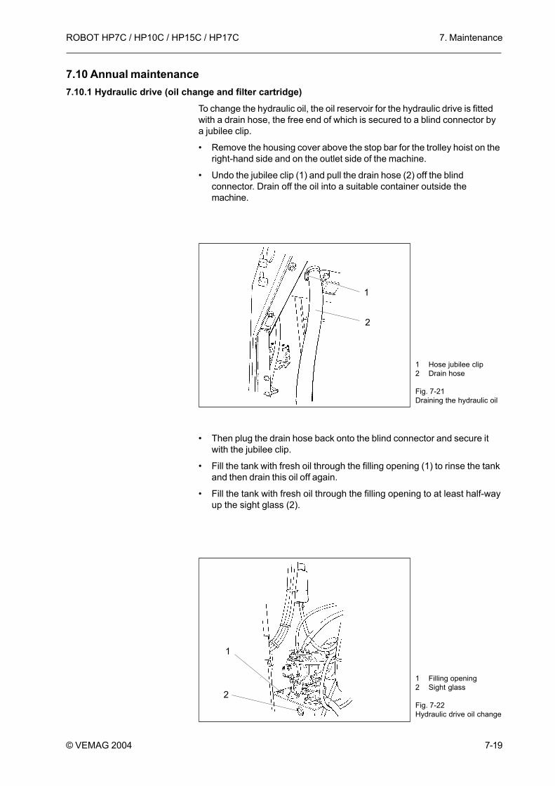
• Undo the jubilee clip (1) and pull the drain hose (2) off the blindconnector. Drain off the oil into a suitable container outside themachine.
• Then plug the drain hose back onto the blind connector and secure itwith the jubilee clip.
• Fill the tank with fresh oil through the filling opening (1) to rinse the tankand then drain this oil off again.
• Fill the tank with fresh oil through the filling opening to at least half-wayup the sight glass (2).
1 Hose jubilee clip2 Drain hose
Fig. 7-21Draining the hydraulic oil
1
2
1 Filling opening2 Sight glass
Fig. 7-22Hydraulic drive oil change
2
1

7. Maintenance
7-20
ROBOT HP7C / HP10C / HP15C / HP17C
© VEMAG 2004
A return filter with a filter cartridge which can be changed is located on thetank of the hydraulic drive.
• Remove the screw cap on the return filter (1) and replace the filtercartridge.
• Then screw the screw cap back onto the filter
• Re-fit the housing cover.
7.10.2 Feed unit drive and feed unit seals• Have the feed unit checked by VEMAG Customer Service and the feed
unit seals replaced.
1 Return filter
Fig. 7-23Filter cartridge for returnfilter
1

7. Maintenance
7-21
ROBOT HP7C / HP10C / HP15C / HP17C
© VEMAG 2004
7.10.3 Vacuum pump (air de-oiling element)The vacuum pump air de-oiling element can become contaminated byparticles of dirt in the air drawn in after a prolonged operating period. As itcannot be cleaned, the air de-oiling element has to be replaced.
Warning!The oil must be drained off before the air de-oiling element is replaced.
Danger!To prevent injury (burns) do not carry out the following work with the pumpstill warm from operation, but wait until the pump has cooled down.
• Lift the vacuum pump forwards out of the machine.Section 7.8.1
• Remove the blow-out cover and the seal.Section 7.8.1
• Undo air deoiler element (1) with the aid of Allen key (2) and pull it out.
• Replace the air deoiler element. Re-use the O-rings.
• Tighten the new air deoiler element hand-tight.
1 Air deoiler element2 Allen key
Fig. 7-24Vacuum pump air de-oiling element
1 2

7. Maintenance
7-22
ROBOT HP7C / HP10C / HP15C / HP17C
© VEMAG 2004
7.11 Biennial maintenance7.11.1 Double screw drive (oil change)
The oil in the double screw drive should be changed every two years.
• Remove the housing cover above the stop bar for the trolley hoist on theright-hand side of the machine.
• Undo the retaining screw and swivel out the electrical case (1).
• Unscrew the cover of the expansion reservoir (2), holding the reservoirsteady in the other hand, and take it out of its bracket. You must holdthe reservoir upright so that no oil escapes. The connecting hose tothe double screw drive is long enough to enable filling to take placeoutside the machine housing.
• Drain the used oil into a suitable container.
• Then fill the expansion reservoir with fresh oil and attach theexpansion reservoir back in its bracket after replenishing it. Check thefilling level. The oil should come at least to the marking on the reservoir.
• Check whether oil is present in coiled relief hose (3) for the seals of thedouble screw drive shafts. If this should be the case, the seals in thedouble screw drive must be replaced, otherwise there is a risk of oilgetting into the double screws.
• Attach the electrical case and re-fit the housing cover.
Warning!Inform VEMAG Customer Service immediately if there is oil in the reliefhose. The seals of the double screw drive must be replaced beforeproduction is resumed.
1 Electrical case2 Expansion reservoir3 Relief hose
Fig. 7-25Changing double screwdrive oil
1
2
3

8. Troubleshooting
8-1
ROBOT HP7C / HP10C / HP15C / HP17C
© VEMAG 2004
8. Troubleshooting8.1 General information
Any attachments or additional devices (optional) which may be presentshould be disconnected from the filling machine for troubleshootingpurposes. The relevant safety instructions must be followed. Possiblefaults, causes and the measures you need to take to remedy them arelisted below.
8.2 Troubleshooting table
Cause
• Step folded out.• Hopper open.• No filling horn holder.
• No mains voltage.
• Main switch not on.• Filling horn holder not closed; hopper
not closed; step not folded up.• Fuse F23/F24/F25 faulty.
• Main drive overheated; fan on oilcooler not running.
• Vacuum drive overheated; vacuumpump full of water.
• Fuse F20/21/22 defective.
• Contactor K2 defective.
• Fuse F50/F51 defective.
• Knee lever switch incorrectly set ordefective.
• Fuse F2/F3/F4/F5/F6/F9 defective orfuse F33 on strip terminal defective.
• Proportional amplifier, relief valve,power electronics or portioningcomputer defective.
• Rotary transducer, drive belt forrotary transducer or wiring for rotarytransducer defective.
Remedy
• Source of fault shown in display.Check part displayed.
• Have machine back-up fusereplaced by electrician.
• Switch on main switch.• Make machine ready for
operation; faults are shown indisplay.
• Have fuses replaced byelectrician.
• Have fuse F30 replaced byelectrician.
• Check vacuum pump; fault isshown in display.
• Have fuses replaced byelectrician.
• Have contactor replaced byelectrician.
• Have fuses on power unitreplaced by electrician.
• Have knee lever switch checkedby electrician and, if necessary,adjusted or replaced.
• Have fuses on power supply unitreplaced by electrician, fault isshown in display.
• Operate test keys 1 + 2 on thepower electronics, check LED,replace defective part.
• Check parts, replace defectivepart, fault is shown in display.
Fault
Machine does not start;display shows ”PLEASESTART MACHINE”.
Main motor and vacuummotor not running.
Main motor running, vacuummotor not running.
Main motor running, butdouble screw drive and feedunit drive not running.

8. Troubleshooting
8-2
ROBOT HP7C / HP10C / HP15C / HP17C
© VEMAG 2004
Cause
• Portioning computer or powerelectronics defective.
• Fuse F1/F8 defective.
• Fuse F31/F32 defective.
• Display, power supply orportioning computer componentdefective.
• Plug connection X12 on portioningcomputer has come loose.
• Wiring defective, valve Y4.
• Power component or portioningcomputer defective.
• Fuse F10/F11/F12 defective.
• Linking gear overloaded.
• Leak in vacuum system.• Water or product residues in line
to display.• Air de-oiling element
contaminated.• Vacuum display defective.
• Valve is not actuated or isdefective.
• Unsuitable or worn double screw.• Vacuum display fluctuating or too
low.
• Air relief bores in double screwhousing blocked.
• Too much air blended in.
• Vacuum system blocked.
Remedy
• Have parts replaced byelectrician.
• Have fuse on power supply unitreplaced by electrician.
• Have fuse on strip terminalreplaced by electrician.
• Replace defective part.
• Have plug connection checked byelectrician.
• Check wiring, voltage is shown byLED at the valve plug.
• Operate test key 3 on the powerelectronics, check LED, replacedefective part.
• Have fuses replaced byelectrician.
• Fault is shown in display.
• Check vacuum system.• Clean or replace line.
• Replace air de-oiling element.
• Replace vacuum display.
• Check valve, voltage is shown byLED below the valve plug.
• Check double screws.• Check vacuum system for leaks,
paying special attention to thedouble screw drive seal. If thevacuum display is fluctuating, thevacuum pump is taking in air. Inthis case, check the float in thevalve.
• Open air relief bore using thesetting screws.
• Use mixing speed during the finalbowl-cutting phase.
• Check complete vacuum systemfor free flow.
Fault
Machine feeds continuouslyin portioning mode.
Display does not light up.
Linking failed orunsatisfactory.
Vacuum level not reached,vacuum unstable.
Lifting/tipping device(optional) not functioning.
Air trapped in product.

8. Troubleshooting
8-3
ROBOT HP7C / HP10C / HP15C / HP17C
© VEMAG 2004
Cause
• Unsuitable double screw.
• Double screw and double screwhousing worn.
• Insufficient vacuum, vacuumunstable (vacuum displayfluctuating).
• Digital rotary transducer defective.• Deformed feed screw, wrong
double screw set.
• Fuse F30 or fan defective.
• Air ducts contaminated.
• Double screw and double screwhousing worn.
• Vacuum too low.
• Deformed feed screw.
• Unsuitable double screw.
• Insufficient vacuum, vacuumunstable (vacuum displayfluctuating).
• Product temperature too high.
Remedy
• Check double screw, use 48 mmdouble screw pitch for portioningsmall portions.
• Measure double screw anddouble screw housing for wearwith a feeler gauge. Air gapbetween screw and housing max.0.5 mm.
• Close air relief bores in doublescrew housing. Check vacuumsystem.
• Replace digital rotary transducer.• Check feed screw. Gap between
bottom edge of feed screw andtop edge of housing must be110 - 120 mm.
• Have defective part replaced byelectrician.
• Clean air ducts.
• Check double screw and doublescrew housing for wear. Measureair gap between double screwand double screw housing.
• Check vacuum setting. Thevacuum should be set so thatthere is no product in the vacuumpot.
• Check feed screw. Gap betweenthe bottom edge of the feed screwand the top edge of the housingmust be 110 - 120 mm.
• Select suitable double screw.Check product feed for lumps.
• Check vacuum system.
• Reduce product temperature.
Fault
Weight fluctuations.
Display ”OIL TEMPERATURETOO HIGH”.
Drop in output.
Raw sausage smears.

8. Troubleshooting
8-4
ROBOT HP7C / HP10C / HP15C / HP17C
© VEMAG 2004

9. Appendix
9-1
ROBOT HP7C / HP10C / HP15C / HP17C
© VEMAG 2004
9. Appendix9.1 General information
Below you will find the technical details relating to the machine andinformation about the lubricants to be used, about accessories and toolsrequired.
Please give the machine number in the event of any query to VEMAGCustomer Service or its agents. You will find this on the rating plate on therear of the filler. It is also embossed on the machine frame.

9. Appendix
9-2
ROBOT HP7C / HP10C / HP15C / HP17C
© VEMAG 2004
9.2 Technical data ROBOT HP7C / HP10C / HP15C / HP17CFilling output HP7C: up to 3,800 kg/h
(depends on feed element)HP10C: up to 5,800 kg/h
(depends on feed element)HP15C: up to 14,000 kg/h
(depends on feed element)HP17C: up to 6,000 kg/h
(depends on feed element)
Portion size: 5 - 60,000 g adjustable in increments of 0.1 g or 1 g
Portion speed: > 700 portions/min. (depends on product, casing and portion size)
Number of links: 0 - 10, infinitely adjustable
Vacuum pump rating: 15 m³/h
Hopper capacity: 250 l/350 l (optional)
Height adjustable by: 80 mm (1,000 - 1,080 mm)
Total weight including lifting/tipping device (optional): approx. 1,300 kg
Noise emission: < 75 dB (A)
Total nominal HP7C: 9.5 kW at 50 Hz / 12 kW at 60 Hzoutput HP10C: 13 kW at 50 Hz / 60 Hz
HP15C: 17 kW at 50 Hz / 60 HzHP17C: 17 kW at 50 Hz / 60 Hz
Main motor HP7C: 7,5 kW at 50 Hz / 12 kW at 60 HzHP10C: 11 kW at 50 Hz / 60 HzHP15C: 15 kW at 50 Hz / 60 HzHP17C: 15 kW at 50 Hz / 60 Hz
Mains voltage Frequency Nominal current Back-up fuse
HP7C/HP10C: 380 - 400 V 50 Hz 21 A 35 A220 - 230 V 50 Hz 36 A 63 A380 - 460 V 60 Hz 20 A 35 A220 - 265 V 60 Hz 35 A 63 A
HP15C/HP17C: 380 - 400 V 50 Hz 27 A 50 A220 - 230 V 50 Hz 47 A 80 A380 - 460 V 60 Hz 25 A 50 A220 - 265 V 60 Hz 46 A 80 A
Electrical fittings: to DIN EN 60204-1
Protection (exterior): IP 65
Protection (interior): IP X3
Type of mains connection for TNS mains equipment protection class I(earth wire)

9. Appendix
9-3
ROBOT HP7C / HP10C / HP15C / HP17C
© VEMAG 2004
9.3 ROBOT HP7C / HP10C / HP15C / HP17C dimensional drawings
250 l hopper350 l hopper
A 2505 2665
B 1340 1400
C 1935 2040
D min. 2940 min. 3040 max. 2995 max. 3090
980
191
C
D
1000
+80
~940
B
1349
max. A

9. Appendix
9-4
ROBOT HP7C / HP10C / HP15C / HP17C
© VEMAG 2004
9.4 Vacuum system
1 Vacuum pump 5 Vacuum display
2 Air filter in intake line 6 Vacuum pot
3 Intake line 7 Float valve
4 Vacuum control valve 8 Exhaust air hose
1
6
2
7
5
34
8

9. Appendix
9-5
ROBOT HP7C / HP10C / HP15C / HP17C
© VEMAG 2004
9.5 Hydraulics plan
Block back-suction
Feed unitOFF
Main drive
Separate linkingLifting/tippingdevice

9. Appendix
9-6
ROBOT HP7C / HP10C / HP15C / HP17C
© VEMAG 2004
A1
F10
A7
T2
T1
K1
16
25
F11
F12
F20
F21
F22
F23
F24
F31
F32
A13
C1
V1
R3
R4
S6
K2
F27
F26
F35
F28
X2
1, 21, 21, 21, 21, 2
1, 2
2, 32, 32, 42, 4
10-15
17
18
18
18
5
19, 20
21, 22
12, 23,24
6
6
7
8
9
9. Appendix
9-7
ROBOT HP7C / HP10C / HP15C / HP17C
© VEMAG 2004
9.6 Electrical control panel 1 Fuse F10-F12, F20-F22
2 Fuse holder
3 Fuse F23, F24
4 Fuse F31, F32
5 Rocker switch for emergencyoperation S6
6 Wire resistor R3, R4
7 Terminal module compl. A7
8 Bridge rectifier V1
9 Capacitor C1
10 Power supply compl. A1
11 Fuse
12 Fuse
13 Fuse
14 Fuse
15 Fuse
16 Hoist module A13
17 Central unit F28
18 Thermistor F26, F27, F35
19 Main contactor K2
20 RC element
21 Transformer T2
22 Fuse
23 Transformer T1
24 Fuse
25 Main contactor K1

9. Appendix
9-8
ROBOT HP7C / HP10C / HP15C / HP17C
© VEMAG 2004
9.7 Power electronics
1 Pressure measuring amplifier2 Plug for pressure sensor3 Plug for valves4 Relief valve control5 Plug for rotary transducer6 Plug for displacement transducer7 Plug strip terminal X88 LED: oil temperature monitor9 LED: main drive motor thermistor fuse10 LED: vacuum motor thermistor fuse11 LED: main contactor K1 (safety chain)12 LED: supply voltage V +24V13 LED: supply voltage LE -15V14 LED: supply voltage LE +15V15 LED: supply voltage PC -15V16 LED: supply voltage PC +15V17 LED: supply voltage F +24V18 Plug for voltage supply19 Plug for PC inputs20 Plug for remote control inputs21 Plug for PC outputs22 Plug for remote control outputs23 LED: feed unit OFF24 LED: feed unit 80
25 Test key: feed unit 8026 LED: feed unit 12527 Test key: feed unit 12528 Test key: linking29 Coding card30 Test key: back-suction31 Test key: fill32 LED: A-C remote control contact33 LED: filling horn holder34 LED: rotary transducer for filling direction35 LED: rotary transducer for pulses36 LED: delayed portioning signal (coex) to remote control socket37 LED: linking or portioning signal to remote control socket38 LED: portioning or clipping signal to remote control socket39 LED: back-suction40 LED: PC enabled41 LED: clip42 LED: remote control43 LED: knee lever44 LED: link45 LED: portion46 Fuse for linking valve47 Fuse for portioning valve
1 47
2
3
4
5
6
7
891011121415 1316171819202122
24
252627
454443
4142
4039383736
353433
31302928
32
23
46

9. Appendix
9-9
ROBOT HP7C / HP10C / HP15C / HP17C
© VEMAG 2004
9.8 Lubricants9.8.1 Double screw driveType of oil: transmission oil
Oil capacity: approx. 3.2 l
Viscosity class: ISO VG 100 to DIN 51519
Quality: C-LP to DIN 51502
Example: Shell Omala oil 100 (order no. 052.001.017)
9.8.2 Hydraulic driveType of oil: hydraulic oil
Oil capacity: approx. 40 l
Viscosity class: ISO VG 46 to DIN 51519
Quality: HLP to DIN 51524
Example: Shell Tellus T46 (order no. 052.001.010)
9.8.3 Vacuum pumpType of oil: compressor oil
Oil capacity: approx. 0.35 l
Viscosity class: ISO VG 100 to DIN 51519
Quality: VBL to DIN 51506
Example: ARAL Motanol HV 100 (order no. 052.001.025)
9.8.4 Feed unit seals and feed unit driveType of grease: high-performance grease which is safe for food use and resistant to
cleaning agents and disinfectants
Example: VEMAG special grease (order no. 052.008.026)
9.8.5 Individual partsType of oil: white oil which is safe for food use and resistant to cleaning agents and
disinfectants
Example: VEMAG special oil (order no. 052.008.021)

9. Appendix
9-10
ROBOT HP7C / HP10C / HP15C / HP17C
© VEMAG 2004
9.9 Accessories9.9.1 Double screw selection
The following double screws are recommended for setting up the fillingmachine as a function of the product to be processed.
Type of double screw Application Order no.48/24-367HPZ Portioning boiled sausage, up to 500 g 915.310.088
72/24-367HPZ Portioning boiled sausage, > 500 g 916.310.088
48C-367HPZ 80/70 Portioning cooked sausage 942.338.000
48-367HPZ Portioning salami without a grinder, up to 500 g 911.310.098
72-367HPZ Portioning salami without a grinder, > 500 g 912.310.098
48C/72SC/48N-367HPZ Portioning salami with a grinder, up to 500 g,grinding meat for processing, minced meat 942.378.639
66C/66SC/48N-367HPZ Portioning salami with a grinder, > 500 ggrinding meat for processing, minced meat 944.378.639
48C-367 Minced meat, for high-temperature applications(soups, sauces, processed curd cheese etc.) 942.378.009
72C/72SC/36N-367HPZ for boiled ham, ground beef 945.348.720
112C/112SC/48N-452HPZ for boiled ham, ground beef 947.448.930
24-367 for coextrusion applications, inner filling up to 50 g 910.310.088
48-367 for coextrusion applications, inner filling > 50 g,outer filling 911.310.098
48/72CSC/36-367 for bakery applications, white bread 915.370.088
72/72CSC/36-452 for bakery applications, wholegrain bread 916.420.088
72CSC/36-367 for bakery applications, mixed-grain and rye bread 916.370.088

9. Appendix
9-11
ROBOT HP7C / HP10C / HP15C / HP17C
© VEMAG 2004
9.9.2 Filling horn selectionThe following filling horns are available for straight filling.
Horn dia. Filling horns Filling horns withø to DIN 9798 crowned outlet8 901.100.080 -
9 901.100.090 -
10 901.100.100 -
12 901.100.120 -
13 901.100.130 -
14 901.100.140 -
15 901.100.150 -
16 901.100.160 901.500.160
18 901.100.180 901.500.180
20 901.100.200 901.500.200
22 901.100.220 901.500.220
24 901.100.240 901.500.240
28 901.100.280 901.500.280
30 901.100.300 901.500.300
35 901.100.350 901.500.350
40 901.100.400 901.500.400
45 901.100.450 -
50 901.100.500 -
55 901.100.550 -
60 901.100.600 -
9.9.3 Linking hornsThe linking horn should be selected as a function of the casing holdingdevice used. To select a suitable linking horn
Casing holding device / Length portioning device operating instructions
9.9.4 Miscellaneous accessories
Component Use Order no.Filling horn holder for 367 mm double screws 936.315.000
Filling horn holder for 454 mm double screws 936.316.002
Filling horn nut for attaching filling horn 930.100.017
Vacuum plug vacuum opening 143.500.510
Cleaning plug vacuum line intake pipe 142.300.600
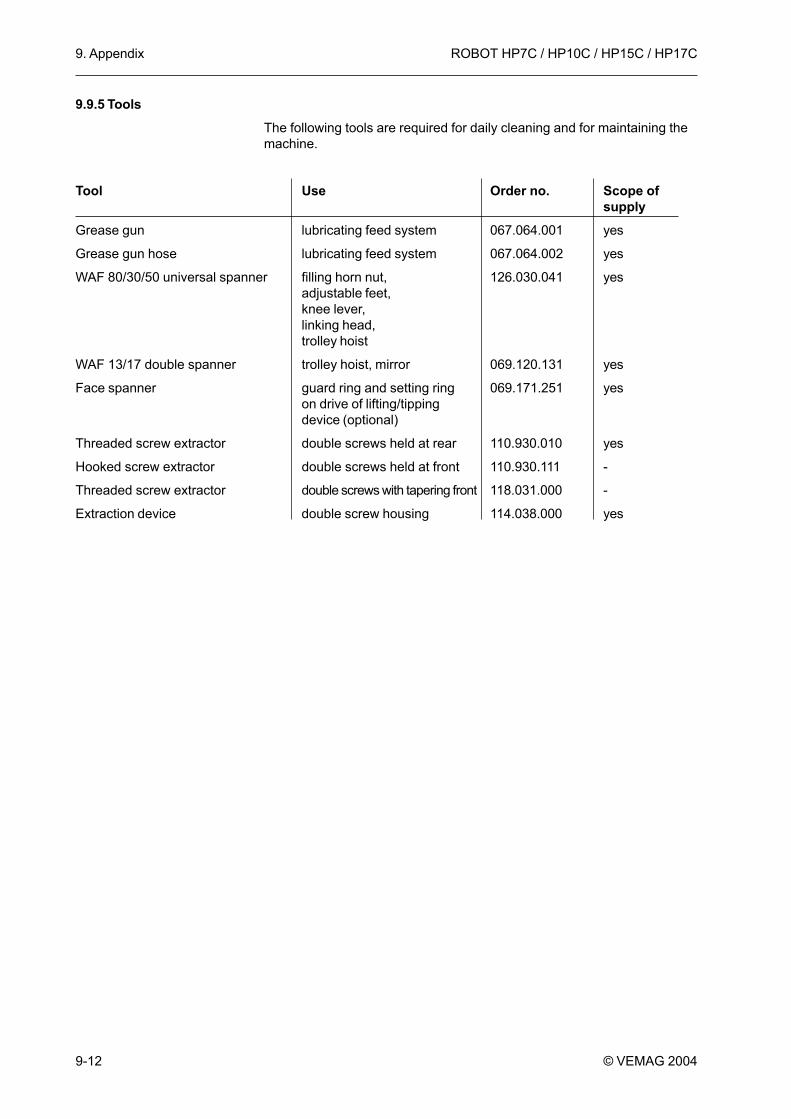
9. Appendix
9-12
ROBOT HP7C / HP10C / HP15C / HP17C
© VEMAG 2004
9.9.5 ToolsThe following tools are required for daily cleaning and for maintaining themachine.
Tool Use Order no. Scope ofsupply
Grease gun lubricating feed system 067.064.001 yes
Grease gun hose lubricating feed system 067.064.002 yes
WAF 80/30/50 universal spanner filling horn nut, 126.030.041 yesadjustable feet,knee lever,linking head,trolley hoist
WAF 13/17 double spanner trolley hoist, mirror 069.120.131 yes
Face spanner guard ring and setting ring 069.171.251 yeson drive of lifting/tippingdevice (optional)
Threaded screw extractor double screws held at rear 110.930.010 yes
Hooked screw extractor double screws held at front 110.930.111 -
Threaded screw extractor double screws with tapering front 118.031.000 -
Extraction device double screw housing 114.038.000 yes