manual qsk23 komatsu
TRANSCRIPT

00-1
SEBM023412
© 2008All Rights ReservedPrinted in Japan 10-08(02)
(12)

00-2 170-3 SERIES
CONTENTS
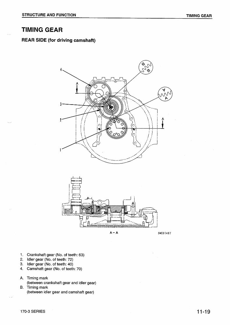
No. of page01 GENERAL ........................................................................................................................... 01-1
11 STRUCTURE AND FUNCTION ........................................................................ 11-1
12 TESTING AND ADJUSTING ............................................................................... 12-1
13 DISASSEMBLY AND ASSEMBLY................................................................ 13-1
14 MAINTENANCE STANDARD ........................................................................... 14-1
15 REPAIR AND REPLACEMENT OF PARTS ........................................ 15-1
(7)

170-3 SERIES 00-2-1
The affected pages are indicated by the use of thefollowing marks. It is requested that necessaryactions be taken to these pages according to thetable below.
Pages having no marks are those previously revisedor made aditions.
Mark Indication Action required
Q Page to be newly added Add
q Page to be replaced Replace
( ) Page to be deleted Discard
LIST OF REVISED PAGES
(12)
Mark Page Revision number
q 00-1 (12)00-2 (7)
q 00-2-1 (12)q 00-2-2 (12)
00-300-400-500-600-700-800-900-1000-1100-1200-1300-1400-1500-1600-1700-1800-1900-2000-2100-22
01-1 (11)01-2 (11)01-4 (10)01-5 (9)01-5-1 (10)01-5-2 (11)01-5-3 (11)01-5-4 (11)01-5-5 (11)01-5-6 (11)01-6 (9)01-7 (10)01-8 (10)01-9 (10)01-10 (10)01-11 (10)01-12 (10)01-13 (10)01-14 (10)
01-15 (10)01-15-1 (10)01-15-2 (10)01-15-3 (10)01-15-4 (10)01-15-5 (10)01-16 (10)01-17 (9)01-18 (3)01-1901-19-1 (9)01-20 (9)01-21 (9)01-22 (9)
11-1 (2)11-2 (11)11-3 (9)11-3-1 (11)11-411-511-611-6-1 (10)11-6-2 (10)11-7 (9)11-8 (9)11-1011-1111-1211-1311-1411-1511-1611-1711-1811-1911-2011-21 (9)11-2211-2411-2511-2611-2711-28
Mark Page Revision number
11-2911-3011-3111-3211-3311-3411-3511-3611-3711-3811-3911-4011-4111-4311-4411-45 (2)11-46 (2)11-47 (2)11-48 (9)11-49 (9)11-50 (2)11-51 (9)11-52 (6)11-53 (9)11-53-1 (6)11-54 (9)11-54-1 (3)11-55 (2)11-56 (2)11-57 (9)11-58 (6)
12-1 (6)12-2 (10)12-3 (10)12-3-1 (11)12-3-2 (11)12-3-3 (11)12-4 (10)12-5 (10)12-5-1 (10)12-6 (5)12-6-1 (5)12-7 (4)
Mark Page Revision number
12-8 (5)12-9 (4)12-10 (6)12-11 (5)12-12 (5)12-13 (5)12-14 (5)12-15 (5)12-16 (4)12-17 (1)12-18 (1)12-19 (1)12-20 (1)12-21 (6)12-22 (6)12-23 (11)12-24 (6)12-25 (10)12-26 (9)12-27 (9)12-27-1 (11)12-27-2 (11)12-101 (6)12-102 (1)12-103 (1)12-104 (6)12-105 (6)12-106 (6)12-106-1 (6)12-107 (10)12-108 (10)12-108-1 (10)12-108-2 (10)12-109 (10)12-110 (6)12-110-1 (6)12-110-2 (6)12-111 (6)12-112 (6)12-112-1 (7)12-112-2 (6)12-113 (6)12-114 (6)12-114-1 (6)
Mark Page Revision number
12-115 (1)12-116 (2)12-117 (6)12-118 (1)12-119 (1)12-120 (1)12-121 (1)12-122 (1)12-123 (4)12-201 (2)12-202 (1)12-203 (1)12-204 (1)12-205 (1)12-206 (2)12-207 (2)12-208 (1)12-209 (1)12-210 (1)12-211 (1)12-212 (2)12-213 (1)12-214 (1)12-215 (2)12-216 (1)12-217 (1)12-218 (1)12-219 (1)12-220 (1)12-221 (1)12-222 (2)12-223 (1)12-224 (1)12-225 (1)12-226 (1)12-227 (1)12-228 (1)12-229 (1)12-230 (1)12-231 (1)12-232 (1)12-233 (1)12-234 (1)12-235 (1)
Mark Page Revision number

00-2-2 170-3 SERIES(12)
12-236 (1)12-237 (1)12-238 (1)12-239 (1)12-240 (1)12-241 (1)12-242 (1)12-243 (1)12-244 (1)12-245 (1)12-246 (1)12-247 (2)12-248 (2)12-248-1 (2)12-249 (1)12-250 (1)12-251 (1)12-252 (1)12-253 (1)12-254 (1)12-255 (1)12-256 (1)12-257 (1)12-258 (1)12-259 (1)12-260 (1)12-261 (1)12-262 (1)12-301 (1)12-302 (1)12-303 (1)12-304 (1)12-305 (1)12-306 (1)12-307 (1)12-308 (1)12-309 (1)12-310 (1)12-311 (1)12-312 (1)12-313 (1)12-314 (1)12-315 (1)12-316 (1)12-317 (1)12-318 (1)12-319 (1)12-320 (1)12-321 (1)12-322 (1)12-323 (1)12-324 (1)12-325 (1)12-326 (1)12-327 (1)
Mark Page Revision number
12-328 (1)12-329 (1)12-330 (1)12-331 (1)12-332 (1)12-333 (1)12-334 (1)12-335 (1)12-336 (1)12-337 (1)12-338 (1)12-339 (1)12-340 (1)12-341 (1)12-342 (1)12-343 (1)12-344 (1)12-345 (1)12-346 (1)12-347 (1)12-348 (1)12-349 (1)12-350 (1)12-351 (1)12-352 (1)12-353 (1)12-354 (1)12-355 (1)12-356 (1)12-357 (1)12-358 (1)12-359 (1)12-360 (1)12-361 (1)12-362 (1)12-363 (1)12-364 (1)12-365 (1)12-366 (1)12-367 (1)
13-113-213-313-413-513-613-713-813-913-1013-1113-1213-1313-14
Mark Page Revision number
13-1513-1613-1713-1813-1913-2013-2113-2213-2313-2413-2513-26 (2)13-27 (10)13-2813-29 (2)13-3013-31 (2)13-3213-3313-3413-3513-3613-37 (2)13-3813-3913-4013-41 (2)13-42 (2)13-43 (2)13-4413-4513-4613-4713-4813-4913-5013-5113-5213-5313-54 (2)13-55 (2)13-56 (2)13-5713-58
14-114-2 (8)14-3 (8)14-3-1 (10)14-3-2 (10)14-3-3 (10)14-3-4 (10)14-414-5 (10)14-6
Mark Page Revision number
14-814-914-1014-1114-1214-1314-1414-1614-1714-1814-2014-2114-2214-23
q 14-24 (12)14-2514-2614-2714-2814-2914-30
15-1 (7)15-2 (7)15-3 (7)15-4 (7)15-5 (7)15-6 (7)15-7 (7)15-8 (7)15-9 (7)15-10 (7)15-11 (7)15-12 (7)15-13 (7)15-14 (7)15-15 (7)15-16 (7)15-17 (7)15-18 (7)15-19 (7)15-20 (7)15-21 (7)15-22 (7)15-23 (7)15-24 (7)15-25 (7)15-26 (7)15-27 (7)15-28 (7)15-29 (7)15-30 (7)15-31 (7)15-32 (7)15-33 (7)
Mark Page Revision number
15-34 (7)15-35 (7)15-36 (7)15-37 (7)15-38 (7)15-39 (7)15-40 (7)15-41 (7)15-42 (7)15-43 (7)15-44 (7)15-45 (7)15-46 (7)15-47 (7)15-48 (7)
Mark Page Revision number

SAFETY SAFETY NOTICE
00-3
SAFETYSAFETY NOTICE
IMPORTANT SAFETY NOTICE
Proper service and repair is extremely important for safe machine operation. The service andrepair techniques recommended by Komatsu and described in this manual are both effectiveand safe. Some of these techniques require the use of tools specially designed by Komatsu forthe specific purpose.
To prevent injury to workers, the symbol k is used to mark safety precautions in this manual.The cautions accompanying these symbols should always be followed carefully. If any danger-ous situation arises or may possibly arise, first consider safety, and take the necessary actionsto deal with the situation.
GENERAL PRECAUTIONS
Mistakes in operation are extremely dangerous.Read the Operation and Maintenance Manual care-fully BEFORE operating the machine.
1. Before carrying out any greasing or repairs, readall the precautions given on the decals which arefixed to the machine.
2. When carrying out any operation, alwayswear safety shoes and helmet. Do not wearloose work clothes, or clothes with buttonsmissing.
• Always wear safety glasses when hittingparts with a hammer.
• Always wear safety glasses when grindingparts with a grinder, etc.
3. If welding repairs are needed, always have atrained, experienced welder carry out the work.When carrying out welding work, always wearwelding gloves, apron, hand shield, cap andother clothes suited for welding work.
4. When carrying out any operation with two ormore workers, always agree on the operatingprocedure before starting. Always inform yourfellow workers before starting any step of theoperation. Before starting work, hang UNDERREPAIR signs on the controls in the operator'scompartment.
5. Keep all tools in good condition and learn thecorrect way to use them.
6. Decide a place in the repair workshop to keeptools and removed parts. Always keep the toolsand parts in their correct places. Always keepthe work area clean and make sure that there isno dirt or oil on the floor. Smoke only in the areasprovided for smoking. Never smoke while work-ing.
PREPARATIONS FOR WORK
7. Before adding oil or making any repairs, park themachine on hard, level ground, and block thewheels or tracks to prevent the machine frommoving.
8. Before starting work, lower blade, ripper, bucketor any other work equipment to the ground. Ifthis is not possible, insert the safety pin or useblocks to prevent the work equipment from fall-ing. In addition, be sure to lock all the controllevers and hang warning signs on them.
9. When disassembling or assembling, support themachine with blocks, jacks or stands beforestarting work.
10.Remove all mud and oil from the steps or otherplaces used to get on and off the machine.Always use the handrails, ladders or steps whengetting on or off the machine. Never jump on oroff the machine. If it is impossible to use thehandrails, ladders or steps, use a stand to pro-vide safe footing.

SAFETY SAFETY NOTICE
00-4
PRECAUTIONS DURING WORK
11.When removing the oil filler cap, drain plug orhydraulic pressure measuring plugs, loosenthem slowly to prevent the oil from spurting out.Before disconnecting or removing componentsof the oil, water or air circuits, first remove thepressure completely from the circuit.
12.The water and oil in the circuits are hot when theengine is stopped, so be careful not to getburned.Wait for the oil and water to cool before carry-ing out any work on the oil or water circuits.
13.Before starting work, remove the leads from thebattery. Always remove the lead from the nega-tive (–) terminal first.
14.When raising heavy components, use a hoist orcrane.Check that the wire rope, chains and hooks arefree from damage.Always use lifting equipment which has amplecapacity.Install the lifting equipment at the correct places.Use a hoist or crane and operate slowly to pre-vent the component from hitting any other part.Do not work with any part still raised by the hoistor crane.
15.When removing covers which are under internalpressure or under pressure from a spring,always leave two bolts in position on oppositesides. Slowly release the pressure, then slowlyloosen the bolts to remove.
16.When removing components, be careful not tobreak or damage the wiring. Damaged wiringmay cause electrical fires.
17.When removing piping, stop the fuel or oil fromspilling out. If any fuel or oil drips onto the floor,wipe it up immediately. Fuel or oil on the floorcan cause you to slip, or can even start fires.
18.As a general rule, do not use gasoline to washparts. In particular, use only the minimum ofgasoline when washing electrical parts.
19.Be sure to assemble all parts again in their origi-nal places.Replace any damaged parts with new parts.• When installing hoses and wires, be sure
that they will not be damaged by contactwith other parts when the machine is beingoperated.
20.When installing high pressure hoses, make surethat they are not twisted. Damaged tubes aredangerous, so be extremely careful when install-ing tubes for high pressure circuits. Also, checkthat connecting parts are correctly installed.
21.When assembling or installing parts, always usethe specified tightening torques. When installingprotective parts such as guards, or parts whichvibrate violently or rotate at high speed, be par-ticularly careful to check that they are installedcorrectly.
22.When aligning two holes, never insert your fin-gers or hand. Be careful not to get your fingerscaught in a hole.
23.When measuring hydraulic pressure, check thatthe measuring tool is correctly assembled beforetaking any measurements.
24.Take care when removing or installing the tracksof track-type machines.When removing the track, the track separatessuddenly, so never let anyone stand at eitherend of the track.

FOREWORD GENERAL
00-5
FOREWORDGENERALThis shop manual has been prepared as an aid to improve the quality of repairs by giving the serviceman anaccurate understanding of the product and by showing him the correct way to perform repairs and make judge-ments. Make sure you understand the contents of this manual and use it to full effect at every opportunity.
This shop manual mainly contains the necessary technical information for operations performed in a serviceworkshop. For ease of understanding, the manual is divided into the following chapters; these chapters are fur-ther divided into the each main group of components.
STRUCTURE AND FUNCTIONThis section explains the structure and function of each component. It serves not only to give an under-standing of the structure, but also serves as reference material for troubleshooting.In addition, this section may contain hydraulic circuit diagrams, electric circuit diagrams, and mainte-nance standards.
TESTING AND ADJUSTINGThis section explains checks to be made before and after performing repairs, as well as adjustments tobe made at completion of the checks and repairs.Troubleshooting charts correlating "Problems" with "Causes" are also included in this section.
DISASSEMBLY AND ASSEMBLYThis section explains the procedures for removing, installing, disassembling and assembling each com-ponent, as well as precautions for them.
MAINTENANCE STANDARDThis section gives the judgment standards for inspection of disassembled parts.The contents of this section may be described in STRUCTURE AND FUNCTION.
OTHERSThis section mainly gives hydraulic circuit diagrams and electric circuit diagrams.In addition, this section may give the specifications of attachments and options together.
NOTICE
The specifications contained in this shop manual are subject to change at any time and without anyadvance notice. Use the specifications given in the book with the latest date.

FOREWORD HOW TO READ THE SHOP MANUAL
00-6
HOW TO READ THE SHOP MANUAL
VOLUMESShop manuals are issued as a guide to carrying outrepairs. They are divided as follows:
Chassis volume: Issued for every machine modelEngine volume: Issued for each engine series
Electrical volume: Attachments volume:
These various volumes are designed to avoid dupli-cating the same information. Therefore, to deal withall repairs for any model , it is necessary that chas-sis, engine, electrical and attachment volumes beavailable.
DISTRIBUTION AND UPDATINGAny additions, amendments or other changes will besent to KOMATSU distributors. Get the most up-to-date information before you start any work.
FILING METHOD1. See the page number on the bottom of the page.
File the pages in correct order.2. Following examples show how to read the page
number.Example 1 (Chassis volume):
10 - 3
Item number (10. Structure andFunction)Consecutive page number for eachitem.
Example 2 (Engine volume):
12 - 5
Unit number (1. Engine)Item number (2. Testing and Adjust-ing)Consecutive page number for eachitem.
3. Additional pages: Additional pages are indicated by a hyphen (-) and number after the page number. File as in the example.Example:10-410-4-110-4-210-5
REVISED EDITION MARK
When a manual is revised, an edit ion mark((1)(2)(3)....) is recorded on the bottom of the pages.
REVISIONS
Revised pages are shown in the LIST OF REVISEDPAGES next to the CONTENTS page.
SYMBOLS
So that the shop manual can be of ample practicaluse, important safety and quality portions aremarked with the following symbols.
Symbol Item Remarks
k SafetySpecial safety precautionsare necessary when per-forming the work.
a Caution
Special technical precau-tions or other precautionsfor preserving standardsare necessary when per-forming the work.
4 Weight
Weight of parts of sys-tems. Caution necessarywhen selecting hoistingwire, or when working pos-ture is important, etc.
3 Tighteningtorque
Places that require specialattention for the tighteningtorque during assembly.
2 CoatPlaces to be coated withadhesives and lubricants,etc.
5 Oil, waterPlaces where oil, water orfuel must be added, andthe capacity.
6 DrainPlaces where oil or watermust be dra ined, andquantity to be drained.
·
Each issued as onevolume to cover allmodels
12-20312-203-112-203-212-204
Added pages

FOREWORD HOISTING INSTRUCTIONS
00-7
HOISTING INSTRUCTIONS
HOISTING
k Heavy parts (25 kg or more) must be liftedwith a hoist, etc. In the DISASSEMBLYAND ASSEMBLY section, every partweighing 25 kg or more is indicated clearlywith the symbol
• If a part cannot be smoothly removed from themachine by hoisting, the following checksshould be made:1) Check for removal of all bolts fastening the
part to the relative parts.2) Check for existence of another part causing
interference with the part to be removed.
WIRE ROPES1) Use adequate ropes depending on the
weight of parts to be hoisted, referring tothe table below:
Wire ropes(Standard "Z" or "S" twist ropes
without galvanizing)
! The allowable load value is estimated to be one-sixth or one-seventh of the breaking strength ofthe rope used.
2) Sling wire ropes from the middle portion of thehook.
Slinging near the edge of the hook may causethe rope to slip off the hook during hoisting, anda serious accident can result. Hooks have max-imum strength at the middle portion.
3) Do not sling a heavy load with one rope alone,but sling with two or more ropes symmetricallywound onto the load.
k Slinging with one rope may cause turningof the load during hoisting, untwisting ofthe rope, or slipping of the rope from itsoriginal winding position on the load, whichcan result in a dangerous accident.
4) Do not sling a heavy load with ropes forming awide hanging angle from the hook.When hoisting a load with two or more ropes,the force subjected to each rope will increasewith the hanging angles. The table belowshows the variation of allowable load kN kgwhen hoisting is made with two ropes, each ofwhich is allowed to sling up to 9.8 kN 1000 kgvertically, at various hanging angles.When two ropes sling a load vertically, up to19.6 kN 2000 kg of total weight can be sus-pended. This weight becomes 9.8 kN 1000 kgwhen two ropes make a 120° hanging angle.On the other hand, two ropes are subjected toan excessive force as large as 39.2 kN 4000kg if they sling a 19.6 kN 2000 kg load at alifting angle of 150°.
Rope diameter Allowable load
mm kN tons
1011.512.514161820
22.430405060
9.813.715.721.627.535.343.154.998.1176.5274.6392.2
1.01.41.62.22.83.64.45.6
10.018.028.040.0
4
SAD00479
41%71%79%88%100%

FOREWORD METHOD OF DISASSEMBLING, CONNECTING PUSH-PULL TYPE COUPLER
00-8
METHOD OF DISASSEMBLING, CONNECTING PUSH-PULL TYPE COUPLER
k Before carrying out the following work, releasethe residual pressure from the hydraulic tank.For details, see TESTING AND ADJUSTING,Releasing residual pressure from hydraulictank.
k Even if the residual pressure is released fromthe hydraulic tank, some hydraulic oil flows outwhen the hose is disconnected. Accordingly,prepare an oil receiving container.
Disconnection1) Release the residual pressure from the hydrau-
lic tank. For detai ls, see TESTING ANDADJUSTING, Releasing residual pressure fromhydraulic tank.
2) Hold adapter (1) and push hose joint (2) intomating adapter (3). (See Fig. 1)! The adapter can be pushed in about 3.5
mm.! Do not hold rubber cap portion (4).
3) After hose joint (2) is pushed into adapter (3),press rubber cap portion (4) against (3) until itclicks. (See Fig. 2)
4) Hold hose adapter (1) or hose (5) and pull it out.(See Fig. 3)! Since some hydraulic oil flows out, prepare
an oil receiving container.
Connection1) Hold hose adapter (1) or hose (5) and insert it in
mating adapter (3), aligning them with eachother. (See Fig. 4)! Do not hold rubber cap portion (4).
2) After inserting the hose in the mating adapterperfectly, pull it back to check its connectingcondition. (See Fig. 5)! When the hose is pulled back, the rubber
cap portion moves toward the hose about3.5 mm. This does not indicate abnormality,however.
Type 1
FOREWORD METHOD OF DISASSEMBLING, CONNECTING PUSH-PULL TYPE COUPLER
00-9
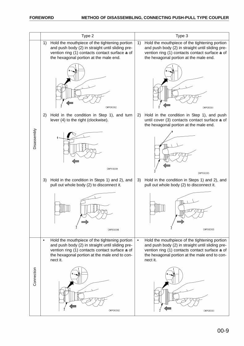
Type 2 Type 3D
isas
sem
bly
1) Hold the mouthpiece of the tightening portionand push body (2) in straight until sliding pre-vention ring (1) contacts contact surface a ofthe hexagonal portion at the male end.
2) Hold in the condition in Step 1), and turnlever (4) to the right (clockwise).
3) Hold in the condition in Steps 1) and 2), andpull out whole body (2) to disconnect it.
1) Hold the mouthpiece of the tightening portionand push body (2) in straight until sliding pre-vention ring (1) contacts contact surface a ofthe hexagonal portion at the male end.
2) Hold in the condition in Step 1), and pushuntil cover (3) contacts contact surface a ofthe hexagonal portion at the male end.
3) Hold in the condition in Steps 1) and 2), andpull out whole body (2) to disconnect it.
Con
nect
ion
• Hold the mouthpiece of the tightening portionand push body (2) in straight until sliding pre-vention ring (1) contacts contact surface a ofthe hexagonal portion at the male end to con-nect it.
• Hold the mouthpiece of the tightening portionand push body (2) in straight until sliding pre-vention ring (1) contacts contact surface a ofthe hexagonal portion at the male end to con-nect it.
FOREWORD COATING MATERIALS
00-10
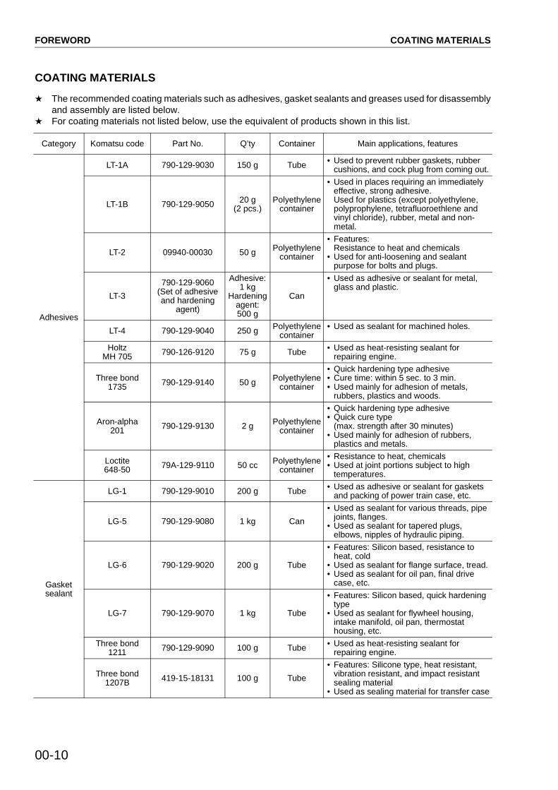
COATING MATERIALS
! The recommended coating materials such as adhesives, gasket sealants and greases used for disassemblyand assembly are listed below.
! For coating materials not listed below, use the equivalent of products shown in this list.
Category Komatsu code Part No. Q’ty Container Main applications, features
Adhesives
LT-1A 790-129-9030 150 g Tube • Used to prevent rubber gaskets, rubber cushions, and cock plug from coming out.
LT-1B 790-129-9050 20 g (2 pcs.)
Polyethylene container
• Used in places requiring an immediately effective, strong adhesive.Used for plastics (except polyethylene, polyprophylene, tetrafluoroethlene and vinyl chloride), rubber, metal and non-metal.
LT-2 09940-00030 50 g Polyethylene container
• Features: Resistance to heat and chemicals
• Used for anti-loosening and sealant purpose for bolts and plugs.
LT-3
790-129-9060(Set of adhesive and hardening
agent)
Adhesive: 1 kg
Hardening agent: 500 g
Can
• Used as adhesive or sealant for metal, glass and plastic.
LT-4 790-129-9040 250 g Polyethylene container
• Used as sealant for machined holes.
Holtz MH 705 790-126-9120 75 g Tube • Used as heat-resisting sealant for
repairing engine.
Three bond 1735 790-129-9140 50 g Polyethylene
container
• Quick hardening type adhesive• Cure time: within 5 sec. to 3 min.• Used mainly for adhesion of metals,
rubbers, plastics and woods.
Aron-alpha 201 790-129-9130 2 g Polyethylene
container
• Quick hardening type adhesive• Quick cure type
(max. strength after 30 minutes)• Used mainly for adhesion of rubbers,
plastics and metals.
Loctite 648-50 79A-129-9110 50 cc Polyethylene
container
• Resistance to heat, chemicals• Used at joint portions subject to high
temperatures.
Gasket sealant
LG-1 790-129-9010 200 g Tube • Used as adhesive or sealant for gaskets and packing of power train case, etc.
LG-5 790-129-9080 1 kg Can
• Used as sealant for various threads, pipe joints, flanges.
• Used as sealant for tapered plugs, elbows, nipples of hydraulic piping.
LG-6 790-129-9020 200 g Tube
• Features: Silicon based, resistance to heat, cold
• Used as sealant for flange surface, tread.• Used as sealant for oil pan, final drive
case, etc.
LG-7 790-129-9070 1 kg Tube
• Features: Silicon based, quick hardening type
• Used as sealant for flywheel housing, intake manifold, oil pan, thermostat housing, etc.
Three bond 1211 790-129-9090 100 g Tube • Used as heat-resisting sealant for
repairing engine.
Three bond 1207B 419-15-18131 100 g Tube
• Features: Silicone type, heat resistant, vibration resistant, and impact resistant sealing material
• Used as sealing material for transfer case

FOREWORD COATING MATERIALS
00-11
Molybdenum disulphide lubricant
LM-G 09940-00051 60 g Can • Used as lubricant for sliding portion (to prevent from squeaking).
LM-P 09940-00040 200 g Tube
• Used to prevent seizure or scuffling of the thread when press fitting or shrink fitting.
• Used as lubricant for linkage, bearings, etc.
Grease
G2-LI
SYG2-400LISYG2-350LISYG2-400LI-ASYG2-160LISYGA-160CNLI
Various Various
• General purpose type
G2-CA
SYG2-400CASYG2-350CASYG2-400CA-ASYG2-160CASYGA-160CNCA
Various Various
• Used for normal temperature, light load bearing at places in contact with water or steam.
Molybdenum disulphide greaseLM-G (G2-M)
SYG2-400MSYG2-400M-ASYGA-16CNM
400 g × 10400 g × 20
16 kg
Bellows typeBellows type
Can
• Used for heavy load portion
Hyper White Grease G2-TG0-T (*)*: For use in
cold district
SYG2-400T-ASYG2-16CNTSYG0-400T-A (*)SYG0-16CNT (*)
400 g16 kg
Bellows typeCan
• Seizure resistance and heat resistance higher than molybdenum disulfide grease
• Since this grease is white, it does not stand out against machine body.
Biogrease G2BG2-BT (*)*: For high
temperature and large load
SYG2-400BSYGA-16CNBSYG2-400BT (*)SYGA-16CNBT (*)
400 g16 kg
Bellows typeCan
• Since this grease is decomposed by bacteria in short period, it has less effects on microorganisms, animals, and plants.
Primer
SUNSTAR PAINT PRIMER 580 SUPER
417-926-3910
20 ml Glass container
Adh
esiv
e fo
r ca
b gl
ass
• Used as primer for cab side (Using limit: 4 months)
SUNSTAR GLASS PRIMER 580 SUPER
20 ml Glass container
• Used as primer for glass side (Using limit: 4 months)
SUNSTAR PAINT PRIMER 435-95
22M-54-27230 20 ml Glass container
• Used as primer for painted surface on cab side (Using limit: 4 months)
SUNSTAR GLASS PRIMER 435-41
22M-54-27240 150 ml Can
• Used as primer for black ceramic-coated surface on glass side and for hard polycarbonate-coated surface(Using limit: 4 months)
SUNSTAR SASH PRIMER GP-402
22M-54-27250 20 ml Glass container
• Used as primer for sash (Alumite).(Using limit: 4 months)
Adhesive
SUNSTAR PENGUINE SUPER 560
22M-54-27210 320 mlEcocart (Special
container)
• Used as adhesive for glass.(Using limit: 6 months)
SUNSTAR PENGUINE SEAL 580 SUPER “S” or “W”
417-926-3910 320 ml Polyethylene container
• “S” is used for high-temperature season (April - October) and “W” for low-temperature season (November - April) as adhesive for glass. (Using limit: 4 months)
Sika Japan, Sikaflex 256HV 20Y-54-39850 310 ml Polyethylene
container• Used as adhesive for glass.
(Using limit: 6 months)
Caulking material
SUNSTAR PENGUINE SEAL No. 2505
417-926-3920 320 ml Polyethylene container
• Used to seal joints of glass parts.(Using limit: 4 months)
SEKISUI SILICONE SEALANT
20Y-54-55130 333 ml Polyethylene container
• Used to seal front window.(Using limit: 6 months)
GE TOSHIBA SILICONES TOSSEAL 381
22M-54-27220 333 ml Cartridge• Used to seal joint of glasses.
Translucent white seal.(Using limit: 12 months)
Category Komatsu code Part No. Q’ty Container Main applications, features

FOREWORD STANDARD TIGHTENING TORQUE
00-12
STANDARD TIGHTENING TORQUE
STANDARD TIGHTENING TORQUE TABLE (WHEN USING TORQUE WRENCH)! In the case of metric nuts and bolts for which there is no special instruction, tighten to the torque given in
the table below.
TABLE OF TIGHTENING TORQUES FOR FLARED NUTS! In the case of flared nuts for which there is no
special instruction, tighten to the torque given inthe table below.
Thread diameter of bolt
Width across flats
Tightening torque
mm mm Nm kgm
68
101214
1013171922
11.8 – 14.727 – 3459 – 7498 – 123
153 – 190
1.2 – 1.52.8 – 3.5
6 – 7.510 – 12.5
15.5 – 19.5
1618202224
2427303236
235 – 285320 – 400455 – 565610 – 765785 – 980
23.5 – 29.533 – 41
46.5 – 5862.5 – 7880 – 100
2730333639
4146505560
1150 – 14401520 – 19101960 – 24502450 – 30402890 – 3630
118 – 147155 – 195200 – 250250 – 310295 – 370
Thread diameter of bolt
Width across flats
Tightening torque
mm mm Nm kgm
68
1012
10131427
5.9 – 9.813.7 – 23.534.3 – 46.174.5 – 90.2
0.6 – 1.01.4 – 2.43.5 – 4.77.6 – 9.2
SAD00483
Sealing surface
Thread diameter Width across flat Tightening torque
mm mm Nm kgm
1418222430333642
1924273236414655
24.5 ± 4.949 ± 19.6
78.5 ± 19.6137.3 ± 29.4176.5 ± 29.4196.1 ± 49245.2 ± 49294.2 ± 49
2.5 ± 0.55 ± 28 ± 2
14 ± 318 ± 320 ± 525 ± 530 ± 5

FOREWORD STANDARD TIGHTENING TORQUE
00-13
TABLE OF TIGHTENING TORQUES FOR SPLIT FLANGE BOLTS! In the case of split flange bolts for which there is no special instruction, tighten to the torque given in the
table below.
TABLE OF TIGHTENING TORQUES FOR O-RING BOSS PIPING JOINTS! Unless there are special instructions, tighten the O-ring boss piping joints to the torque below.
TABLE OF TIGHTENING TORQUES FOR O-RING BOSS PLUGS! Unless there are special instructions, tighten the O-ring boss plugs to the torque below.
Thread diameter Width across flat Tightening torque
mm mm Nm kgm
101216
141722
59 – 7498 – 123
235 – 285
6 – 7.5 10 – 12.5
23.5 – 29.5
Norminal No.Thread diameter Width across flat Tightening torque (Nm kgm)
mm mm Range Target
0203, 0405, 0610, 12
14
1420243342
Varies depending on type of connector.
35 – 63 3.5 – 6.584 – 132 8.5 – 13.5
128 – 186 13.0 – 19.0363 – 480 37.0 – 49.0
746 – 1010 76.0 – 103
44 4.5103 10.5157 16.0422 43.0883 90.0
Norminal No.Thread diameter Width across flat Tightening torque (Nm kgm)
mm mm Range Target
08101214161820243033364252
08101214161820243033364252
141719222427303232—36——
5.88 – 8.82 0.6 – 0.99.8 – 12.74 1.0 – 1.314.7 – 19.6 1.5 – 2.019.6 – 24.5 2.0 – 2.524.5 – 34.3 2.5 – 3.534.3 – 44.1 3.5 – 4.544.1 – 53.9 4.5 – 5.558.8 – 78.4 6.0 – 8.0
93.1 – 122.5 9.5 – 12.5107.8 – 147.0 11.0 – 15.0127.4 – 176.4 13.0 – 18.0181.3 – 240.1 18.5 – 24.5274.4 – 367.5 28.0 – 37.5
7.35 0.7511.27 1.1517.64 1.822.54 2.329.4 3.039.2 4.049.0 5.068.6 7.0
107.8 11.0124.4 13.0151.9 15.5210.7 21.5323.4 33.0

FOREWORD STANDARD TIGHTENING TORQUE
00-14
TIGHTENING TORQUE FOR 102 AND 114 ENGINE SERIES 1) BOLT AND NUTS
Use these torques for bolts and nuts (unit: mm) of Cummins Engine.
2) EYE JOINTSUse these torques for eye joints (unit: mm) of Cummins Engine.
3) TAPERED SCREWSUse these torques for tapered screws (unit: inch) of Cummins Engine.
TIGHTENING TORQUE TABLE FOR HOSES (TAPER SEAL TYPE AND FACE SEAL TYPE)! Tighten the hoses (taper seal type and face seal type) to the following torque, unless otherwise specified.! Apply the following torque when the threads are coated (wet) with engine oil.
Thread diameter Tightening torque
mm Nm kgm
68
1012
10 ± 224 ± 443 ± 6
77 ± 12
1.02 ± 0.202.45 ± 0.414.38 ± 0.617.85 ± 1.22
Thread diameter Tightening torque
mm Nm kgm
68
101214
8 ± 210 ± 212 ± 224 ± 436 ± 5
0.81 ± 0.201.02 ± 0.201.22 ± 0.202.45 ± 0.413.67 ± 0.51
Thread diameter Tightening torque
inch Nm kgm
1 / 161 / 81 / 43 / 81 / 23 / 4
1
3 ± 1 8 ± 212 ± 215 ± 224 ± 436 ± 560 ± 9
0.31 ± 0.100.81 ± 0.201.22 ± 0.201.53 ± 0.202.45 ± 0.413.67 ± 0.516.12 ± 0.92
Nominal size of hose
Width across flats
Tightening torque (Nm kgm) Taper seal type Face seal type
Range Target Thread size (mm)
Nominal thread size - Threads per inch, Thread series
Root diameter (mm) (Reference)
02 1934 – 54 3.5 – 5.5 44 4.5 – – 18UN 14.3
34 – 63 3.5 – 6.5 44 4.5 14 – –
0322 54 – 93 5.5 – 9.5 74 7.5 – – 16UN 17.5
24 59 – 98 6.0 – 10.0 78 8.0 18 – –
04 27 84 – 132 8.5 – 13.5 103 10.5 22 – 16UN 20.6
05 32 128 – 186 13.0 – 19.0 157 16.0 24 1 – 14UNS 25.4
06 36 177 – 245 18.0 – 25.0 216 22.0 30 1 – 12UN 30.2
(10) 41 177 – 245 18.0 – 25.0 216 22.0 33 – –
(12) 46 197 – 294 20.0 – 30.0 245 25.0 36 – –
(14) 55 246 – 343 25.0 – 35.0 294 30.0 42 – –
9—16
11—16
13—16
3—16

FOREWORD ELECTRIC WIRE CODE
00-15
ELECTRIC WIRE CODEIn the wiring diagrams, various colors and symbols are employed to indicate the thickness of wires.This wire code table will help you understand WIRING DIAGRAMS.Example: 5WB indicates a cable having a nominal number 5 and white coating with black stripe.
CLASSIFICATION BY THICKNESS
CLASSIFICATION BY COLOR AND CODE
Norminalnumber
Copper wire
Cable O.D.(mm)
Current rating
(A)Applicable circuit
Number of strands
Dia. of strands(mm2)
Cross section(mm2)
0.85 11 0.32 0.88 2.4 12 Starting, lighting, signal etc.
2 26 0.32 2.09 3.1 20 Lighting, signal etc.
5 65 0.32 5.23 4.6 37 Charging and signal
15 84 0.45 13.36 7.0 59 Starting (Glow plug)
40 85 0.80 42.73 11.4 135 Starting
60 127 0.80 63.84 13.6 178 Starting
100 217 0.80 109.1 17.6 230 Starting
Priori-ty
Circuits
Classi-fication
Charging Ground Starting Lighting Instrument Signal Other
1 Pri-mary
Code W B B R Y G L
Color White Black Black Red Yellow Green Blue
2
Auxi-liary
Code WR — BW RW YR GW LW
Color White & Red — White & Black Red & White Rellow & Red Green & White Blue & White
3Code WB — BY RB YB GR LR
Color White & Black — Black & Yellow Red & Black Yellow & Black Green & Red Blue & Yellow
4
Code WL — BR RY YG GY LY
Color White & Blue — Black & Red Red & Yellow Yellow & Green
Green & Yellow Blue & Yellow
5Code WG — — RG YL GB LB
Color White & Green — — Red & Green Yellow & Blue Green & Black Blue & Black
6Code — — — RL YW GL —
Color — — — Red & Blue Yellow & White Green & Blue —

FOREWORD CONVERSION TABLE
00-16
CONVERSION TABLE
METHOD OF USING THE CONVERSION TABLEThe Conversion Table in this section is provided to enable simple conversion of figures. For details of themethod of using the Conversion Table, see the example given below.
EXAMPLE• Method of using the Conversion Table to convert from millimeters to inches1. Convert 55 mm into inches.
(1) Locate the number 50 in the vertical column at the left side, take this as (A), then draw a horizontal linefrom (A).
(2) Locate the number 5 in the row across the top, take this as (B), then draw a perpendicular line downfrom (B).
(3) Take the point where the two lines cross as (C). This point (C) gives the value when converting frommillimeters to inches. Therefore, 55 mm = 2.165 inches.
2. Convert 550 mm into inches.(1) The number 550 does not appear in the table, so divide by 10 (move the decimal point one place to the
left) to convert it to 55 mm.(2) Carry out the same procedure as above to convert 55 mm to 2.165 inches.(3) The original value (550 mm) was divided by 10, so multiply 2.165 inches by 10 (move the decimal point
one place to the right) to return to the original value. This gives 550 mm = 21.65 inches.
Millimeters to inches
1 mm = 0.03937 in
0 1 2 3 4 5 6 7 8 9
010203040
5060708090
00.3940.7871.1811.575
1.9692.3622.7563.1503.543
0.0390.4330.8271.2201.614
2.0082.4022.7953.1893.583
0.0790.4720.8661.2601.654
2.0472.4412.8353.2283.622
0.1180.5120.9061.2991.693
2.0872.4802.8743.2683.661
0.1570.5510.9451.3391.732
2.1262.5202.9133.3073.701
0.1970.5910.9841.3781.772
2.1652.5592.9533.3463.740
0.2360.6301.0241.4171.811
2.2052.5982.9923.3863.780
0.2760.6691.0631.4571.850
2.2442.6383.0323.4253.819
0.3150.7091.1021.4961.890
2.2832.6773.0713.4653.858
0.3540.7481.1421.5361.929
2.3232.7173.1103.5043.898
(A)
(B)
(C)
FOREWORD CONVERSION TABLE
00-17
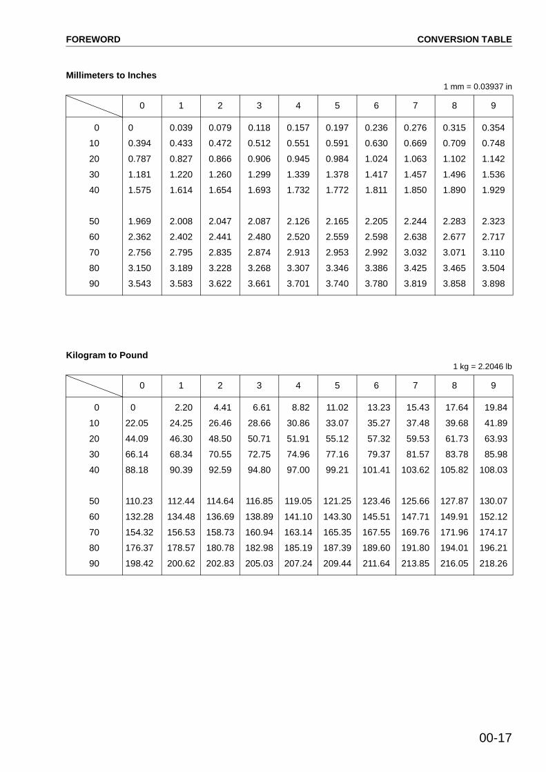
Millimeters to Inches1 mm = 0.03937 in
Kilogram to Pound1 kg = 2.2046 lb
0 1 2 3 4 5 6 7 8 9
0
10
20
30
40
50
60
70
80
90
0
0.394
0.787
1.181
1.575
1.969
2.362
2.756
3.150
3.543
0.039
0.433
0.827
1.220
1.614
2.008
2.402
2.795
3.189
3.583
0.079
0.472
0.866
1.260
1.654
2.047
2.441
2.835
3.228
3.622
0.118
0.512
0.906
1.299
1.693
2.087
2.480
2.874
3.268
3.661
0.157
0.551
0.945
1.339
1.732
2.126
2.520
2.913
3.307
3.701
0.197
0.591
0.984
1.378
1.772
2.165
2.559
2.953
3.346
3.740
0.236
0.630
1.024
1.417
1.811
2.205
2.598
2.992
3.386
3.780
0.276
0.669
1.063
1.457
1.850
2.244
2.638
3.032
3.425
3.819
0.315
0.709
1.102
1.496
1.890
2.283
2.677
3.071
3.465
3.858
0.354
0.748
1.142
1.536
1.929
2.323
2.717
3.110
3.504
3.898
0 1 2 3 4 5 6 7 8 9
0
10
20
30
40
50
60
70
80
90
0
22.05
44.09
66.14
88.18
110.23
132.28
154.32
176.37
198.42
2.20
24.25
46.30
68.34
90.39
112.44
134.48
156.53
178.57
200.62
4.41
26.46
48.50
70.55
92.59
114.64
136.69
158.73
180.78
202.83
6.61
28.66
50.71
72.75
94.80
116.85
138.89
160.94
182.98
205.03
8.82
30.86
51.91
74.96
97.00
119.05
141.10
163.14
185.19
207.24
11.02
33.07
55.12
77.16
99.21
121.25
143.30
165.35
187.39
209.44
13.23
35.27
57.32
79.37
101.41
123.46
145.51
167.55
189.60
211.64
15.43
37.48
59.53
81.57
103.62
125.66
147.71
169.76
191.80
213.85
17.64
39.68
61.73
83.78
105.82
127.87
149.91
171.96
194.01
216.05
19.84
41.89
63.93
85.98
108.03
130.07
152.12
174.17
196.21
218.26

FOREWORD CONVERSION TABLE
00-18
Liter to U.S. Gallon1l = 0.2642 U.S. Gal
Liter to U.K. Gallon1l = 0.21997 U.K. Gal
0 1 2 3 4 5 6 7 8 9
0
10
20
30
40
50
60
70
80
90
0
2.642
5.283
7.925
10.567
13.209
15.850
18.492
21.134
23.775
0.264
2.906
5.548
8.189
10.831
13.473
16.115
18.756
21.398
24.040
0.528
3.170
5.812
8.454
11.095
13.737
16.379
19.020
21.662
24.304
0.793
3.434
6.076
8.718
11.359
14.001
16.643
19.285
21.926
24.568
1.057
3.698
6.340
8.982
11.624
14.265
16.907
19.549
22.190
24.832
1.321
3.963
6.604
9.246
11.888
14.529
17.171
19.813
22.455
25.096
1.585
4.227
6.869
9.510
12.152
14.795
17.435
20.077
22.719
25.361
1.849
4.491
7.133
9.774
12.416
15.058
17.700
20.341
22.983
25.625
2.113
4.755
7.397
10.039
12.680
15.322
17.964
20.605
23.247
25.889
2.378
5.019
7.661
10.303
12.944
15.586
18.228
20.870
23.511
26.153
0 1 2 3 4 5 6 7 8 9
0
10
20
30
40
50
60
70
80
90
0
2.200
4.399
6.599
8.799
10.998
13.198
15.398
17.598
19.797
0.220
2.420
4.619
6.819
9.019
11.281
13.418
15.618
17.818
20.017
0.440
2.640
4.839
7.039
9.239
11.438
13.638
15.838
18.037
20.237
0.660
2.860
5.059
7.259
9.459
11.658
13.858
16.058
18.257
20.457
0.880
3.080
5.279
7.479
9.679
11.878
14.078
16.278
18.477
20.677
1.100
3.300
5.499
7.969
9.899
12.098
14.298
16.498
18.697
20.897
1.320
3.520
5.719
7.919
10.119
12.318
14.518
16.718
18.917
21.117
1.540
3.740
5.939
8.139
10.339
12.528
14.738
16.938
19.137
21.337
1.760
3.950
6.159
8.359
10.559
12.758
14.958
17.158
19.357
21.557
1.980
4.179
6.379
8.579
10.778
12.978
15.178
17.378
19.577
21.777

FOREWORD CONVERSION TABLE
00-19
kgm to ft. lb1 kgm = 7.233 ft. lb
0 1 2 3 4 5 6 7 8 9
0
10
20
30
40
50
60
70
80
90
100
110
120
130
140
150
160
170
180
190
0
72.3
144.7
217.0
289.3
361.7
434.0
506.3
578.6
651.0
723.3
795.6
868.0
940.3
1012.6
1084.9
1157.3
1129.6
1301.9
1374.3
7.2
79.6
151.9
224.2
296.6
368.9
441.2
513.5
585.9
658.2
730.5
802.9
875.2
947.5
1019.9
1092.2
1164.5
1236.8
1309.2
1381.5
14.5
86.8
159.1
231.5
303.8
376.1
448.5
520.8
593.1
665.4
737.8
810.1
882.4
954.8
1027.1
1099.4
1171.7
1244.1
1316.4
1388.7
21.7
94.0
166.4
238.7
311.0
383.4
455.7
528.0
600.3
672.7
745.0
817.3
889.7
962.0
1034.3
1106.6
1179.0
1251.3
1323.6
1396.0
28.9
101.3
173.6
245.9
318.3
390.6
462.9
535.2
607.6
679.9
752.2
824.6
896.9
969.2
1041.5
1113.9
1186.2
1258.5
1330.9
1403.2
36.2
108.5
180.8
253.2
325.5
397.8
470.2
542.5
614.8
687.1
759.5
831.8
904.1
976.5
1048.8
1121.1
1193.4
1265.8
1338.1
1410.4
43.4
115.7
188.1
260.4
332.7
405.1
477.4
549.7
622.0
694.4
766.7
839.0
911.4
983.7
1056.0
1128.3
1200.7
1273.0
1345.3
1417.7
50.6
123.0
195.3
267.6
340.0
412.3
484.6
556.9
629.3
701.6
773.9
846.3
918.6
990.9
1063.2
1135.6
1207.9
1280.1
1352.6
1424.9
57.9
130.2
202.5
274.9
347.2
419.5
491.8
564.2
636.5
708.8
781.2
853.5
925.8
998.2
1070.5
1142.8
1215.1
1287.5
1359.8
1432.1
65.1
137.4
209.8
282.1
354.4
426.8
499.1
571.4
643.7
716.1
788.4
860.7
933.1
1005.4
1077.7
1150.0
1222.4
1294.7
1367.0
1439.4

FOREWORD CONVERSION TABLE
00-20
kg/cm2 to lb/in2
1kg/cm2 = 14.2233 lb/in2
0 1 2 3 4 5 6 7 8 9
0
10
20
30
40
50
60
70
80
90
100
110
120
130
140
150
160
170
180
190
200
210
220
230
240
0
142.2
284.5
426.7
568.9
711.2
853.4
995.6
1138
1280
1422
1565
1707
1849
1991
2134
2276
2418
2560
2702
2845
2987
3129
3271
3414
14.2
156.5
298.7
440.9
583.2
725.4
867.6
1010
1152
1294
1437
1579
1721
1863
2005
2148
2290
2432
2574
2717
2859
3001
3143
3286
3428
28.4
170.7
312.9
455.1
597.4
739.6
881.8
1024
1166
1309
1451
1593
1735
1877
2020
2162
2304
2446
2589
2731
2873
3015
3158
3300
3442
42.7
184.9
327.1
469.4
611.6
753.8
896.1
1038
1181
1323
1465
1607
1749
1892
2034
2176
2318
2460
2603
2745
2887
3030
3172
3314
3456
56.9
199.1
341.4
483.6
625.8
768.1
910.3
1053
1195
1337
1479
1621
1764
1906
2048
2190
2333
2475
2617
2759
2901
3044
3186
3328
3470
71.1
213.4
355.6
497.8
640.1
782.3
924.5
1067
1209
1351
1493
1636
1778
1920
2062
2205
2347
2489
2631
2773
2916
3058
3200
3343
3485
85.3
227.6
369.8
512.0
654.3
796.5
938.7
1081
1223
1365
1508
1650
1792
1934
2077
2219
2361
2503
2646
2788
2930
3072
3214
3357
3499
99.6
241.8
384.0
526.3
668.5
810.7
953.0
1095
1237
1380
1522
1664
1806
1949
2091
2233
2375
2518
2660
2802
2944
3086
3229
3371
3513
113.8
256.0
398.3
540.5
682.7
825.0
967.2
1109
1252
1394
1536
1678
1821
1963
2105
2247
2389
2532
2674
2816
2958
3101
3243
3385
3527
128.0
270.2
412.5
554.7
696.9
839.2
981.4
1124
1266
1408
1550
1693
1835
1977
2119
2262
2404
2546
2688
2830
2973
3115
3257
3399
3542
FOREWORD CONVERSION TABLE
00-21
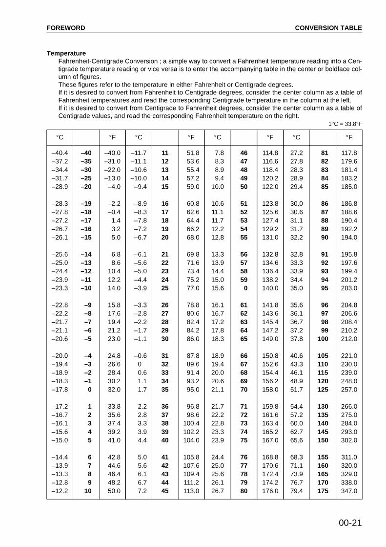
TemperatureFahrenheit-Centigrade Conversion ; a simple way to convert a Fahrenheit temperature reading into a Cen-tigrade temperature reading or vice versa is to enter the accompanying table in the center or boldface col-umn of figures.These figures refer to the temperature in either Fahrenheit or Centigrade degrees.If it is desired to convert from Fahrenheit to Centigrade degrees, consider the center column as a table ofFahrenheit temperatures and read the corresponding Centigrade temperature in the column at the left.If it is desired to convert from Centigrade to Fahrenheit degrees, consider the center column as a table ofCentigrade values, and read the corresponding Fahrenheit temperature on the right.
1°C = 33.8°F
°C °F °C °F °C °F °C °F
–40.4–37.2–34.4–31.7–28.9
–28.3–27.8–27.2–26.7–26.1
–25.6–25.0–24.4–23.9–23.3
–22.8–22.2–21.7–21.1–20.6
–20.0–19.4–18.9–18.3–17.8
–17.2–16.7–16.1–15.6–15.0
–14.4–13.9–13.3–12.8–12.2
–40–35–30–25–20
–19–18–17–16–15
–14–13–12–11–10
–9 –8 –7 –6 –5
–4 –3 –2 –1 0
1 2 3 4 5
6 7 8 9 10
–40.0–31.0–22.0–13.0 –4.0
–2.2 –0.4 1.4 3.2 5.0
6.8 8.6 10.4 12.2 14.0
15.8 17.6 19.4 21.2 23.0
24.8 26.6 28.4 30.2 32.0
33.8 35.6 37.4 39.2 41.0
42.8 44.6 46.4 48.2 50.0
–11.7–11.1–10.6–10.0 –9.4
–8.9 –8.3 –7.8 –7.2 –6.7
–6.1 –5.6 –5.0 –4.4 –3.9
–3.3 –2.8 –2.2 –1.7 –1.1
–0.6 0
0.6 1.1 1.7
2.2 2.8 3.3 3.9 4.4
5.0 5.6 6.1 6.7 7.2
1112131415
1617181920
2122232425
2627282930
3132333435
3637383940
4142434445
51.8 53.6 55.4 57.2 59.0
60.8 62.6 64.4 66.2 68.0
69.8 71.6 73.4 75.2 77.0
78.8 80.6 82.4 84.2 86.0
87.8 89.6 91.4 93.2 95.0
96.8 98.6100.4102.2104.0
105.8107.6109.4111.2113.0
7.8 8.3 8.9 9.410.0
10.611.111.712.212.8
13.313.914.415.015.6
16.116.717.217.818.3
18.919.420.020.621.1
21.722.222.823.323.9
24.425.025.626.126.7
4647484950
5152535455
56575859 0
6162636465
6667686970
7172737475
7677787980
114.8116.6118.4120.2122.0
123.8125.6127.4129.2131.0
132.8134.6136.4138.2140.0
141.8143.6145.4147.2149.0
150.8152.6154.4156.2158.0
159.8161.6163.4165.2167.0
168.8170.6172.4174.2176.0
27.227.828.328.929.4
30.030.631.131.732.2
32.833.333.934.435.0
35.636.136.737.237.8
40.643.346.148.951.7
54.457.260.062.765.6
68.371.173.976.779.4
81 82 83 84 85
86 87 88 89 90
91 92 93 94 95
96 97 98 99100
105110115120125
130135140145150
155160165170175
117.8179.6181.4183.2185.0
186.8188.6190.4192.2194.0
195.8197.6199.4201.2203.0
204.8206.6208.4210.2212.0
221.0230.0239.0248.0257.0
266.0275.0284.0293.0302.0
311.0320.0329.0338.0347.0

FOREWORD UNITS
00-22 04-05
UNITS
In this manual, the measuring units are indicated with Internatinal System of units (SI).As for reference, conventionally used Gravitational System of units are indicated in parentheses .
Example:N kgNm kgmMPa kg/cm2kPa mmH2OkPa mmHgkW/rpm HP/rpmg/kWh g/HPh
170-3 SERIES 01-1
Applicable machine ........................................... 01- 2Specifications .................................................... 01- 4Overall drawing ................................................ 01-5-3Weight table ...................................................... 01-16Engine performance curve ................................ 01-17
01 GENERAL
(11)

01-2 170-3 SERIES
GENERAL APPLICABLE MACHINE
APPPLICABLE MACHINE
Engine Engine Serial No. Applicable machine
SA6D170E-3 D375A-5 Bulldozer
SAA6D170E-3
PC1250-7
WA600-3
WA700-3
WD600-3
HD465-7
HD605-7
Generator
Hydraulic excavator
Wheel loader
Wheel loader
Wheel dozer
Dump truck
Dump truck
Generator
SAA6D170E2-3 DCA-800SSK2 (DENYO GENERATOR)
Generator
SAA6D170E-P910 EGS950-6 Generator
SAA6D170E-P970 EGS1050-7 Generator
(11)

01-4 170-3 SERIES
GENERAL
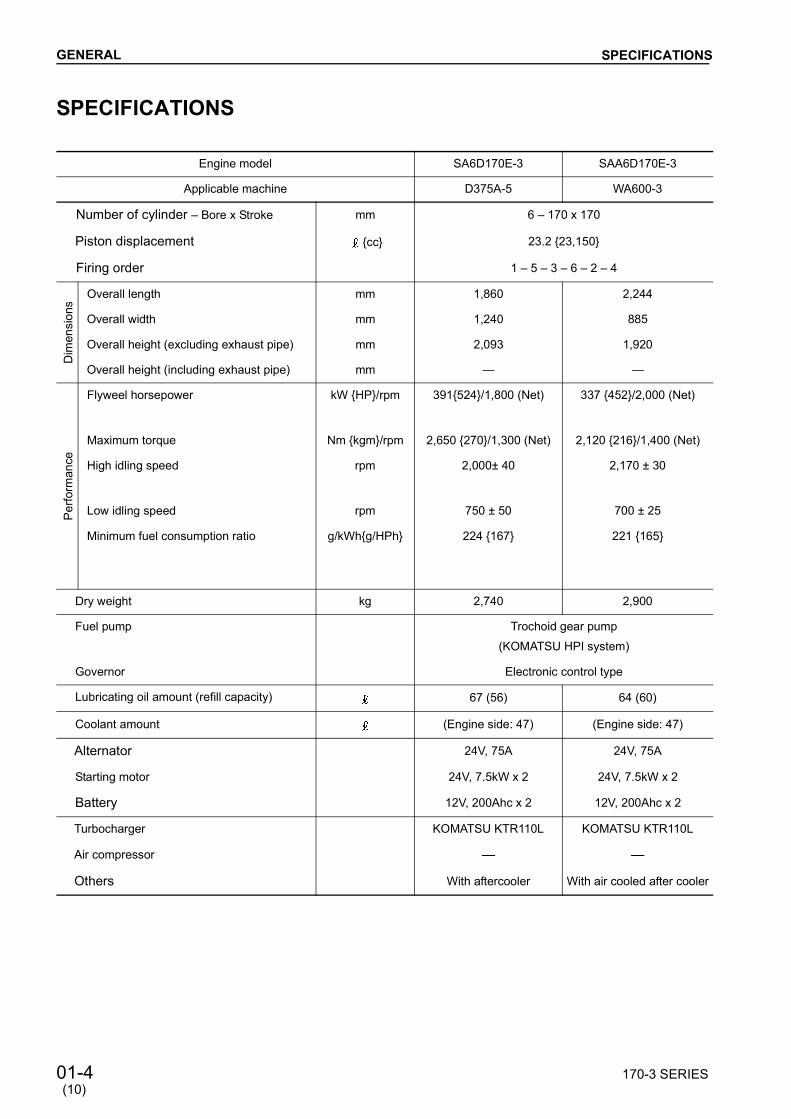
SPECIFICATIONS
Engine model SA6D170E-3 SAA6D170E-3
Applicable machine D375A-5 WA600-3
Number of cylinder Bore x Stroke mm 6 170 x 170
Piston displacement cc 23.2 23,150
Firing order 1 5 3 6 2 4
Dim
ensi
ons
Overall length mm 1,860 2,244
Overall width mm 1,240 885
Overall height (excluding exhaust pipe) mm 2,093 1,920
Overall height (including exhaust pipe) mm
Per
form
ance
Flyweel horsepower kW HP/rpm 391524/1,800 (Net) 337 452/2,000 (Net)
Maximum torque Nm kgm/rpm 2,650 270/1,300 (Net) 2,120 216/1,400 (Net)
High idling speed rpm 2,000± 40 2,170 ± 30
Low idling speed rpm 750 ± 50 700 ± 25
Minimum fuel consumption ratio g/kWhg/HPh 224 167 221 165
Dry weight kg 2,740 2,900
Fuel pump Trochoid gear pump
(KOMATSU HPI system)
Governor Electronic control type
Lubricating oil amount (refill capacity) 67 (56) 64 (60)
Coolant amount (Engine side: 47) (Engine side: 47)
Alternator 24V, 75A 24V, 75A
Starting motor 24V, 7.5kW x 2 24V, 7.5kW x 2
Battery 12V, 200Ahc x 2 12V, 200Ahc x 2
Turbocharger KOMATSU KTR110L KOMATSU KTR110L
Air compressor
Others With aftercooler With air cooled after cooler
SPECIFICATIONS
(10)

170-3 SERIES 01-5
GENERAL SPECIFICATIONS
SAA6D170E-3
WA700-3 WD600-3 PC1250-7 HD465-7HD605-7
6 - 170 x 170
23.2 23,150
1 5 3 6 2 4
2,389 2,244 2,235 2,057
1,220 1,138 1,235 1,250
1,138 1,936 1,644
1,733 1,138
478641/2,000 (Net)2,806 286/1,400 (Net)
370497/2,000 (Net)2,391 244/1,400 (Net)
485 651/1,800 (Net)2,913 297/1,300 (Net)
533 715/2,000 (Net)3,207 327/1,400 (Net)
2,240 ± 30 2,190 ± 30 2,000 ± 40 2,270 ± 50
725 ± 25 700 ± 25 900 ± 25 750 ± 50
212 157 222 163 218 160 211 155
3,100 2,900 2,870 2,740
Trochoid gear pump (KOMATSU HPI system)
Electronic control type
67 (56) 64 (60) 67 (56) 67 (56)
(Engine side: 47) (Engine side: 47) (Engine side: 47) (Engine side: 47)
24V, 75A 24V, 75A 24V, 150A 24V, 50A
24V, 7.5kW x 2 24V, 7.5kW x 2 24V, 11kW x 2 24V, 7.5kW x 2
12V, 200Ah x 2 12V, 200Ah x 2 12V, 200Ah x 2 12V, 200Ah x 2
SCHWITZER S500 KOMATSU KTR110L SCHWITZER S500 SCHWITZER S500
Recipro type, single cylinder
With air cooled aftercooler With air cooled aftercooler With air cooled aftercooler With air cooled aftercooler
(9)

01-5-1 170-3 SERIES
GENERAL SPECIFICATIONS
Engine model SAA6D170E-3 SAA6D170E2-3
Applicable machine Generator DCA-800SSK2 (DENYO GENERATOR)
Number of cylinder Bore x Stroke mm 6 170 x 170
Piston displacement cc 23.2 23,150
Firing order 1 5 3 6 2 4
Dim
ensi
ons
Overall length mm 2,638 2,672
Overall width mm 1,073 1,081
Overall height (excluding exhaust pipe) mm 1,815 1,716
Overall height (including exhaust pipe) mm
Per
form
ance
Flyweel horsepower kW HP/rpm 548 735/1,500 (50Hz) (Net)
548 735/1,800 (60Hz) (Net)
752 1,008/1,800 (50Hz) (Net)
Maximum torque Nm kgm/rpm
High idling speed rpm Max. 1,575 (50Hz)
Max. 1,890 (60Hz)
Max. 1,890 (60Hz)
Low idling speed rpm 800 ± 50 875 ± 25
Minimum fuel consumption ratio g/kWhg/HPh (Rated output)
203 151 (50Hz)
212 158 (60Hz)
198 148 (60Hz)
Dry weight kg 2,565 2,597
Fuel pump Trochoid gear pump
(KOMATSU HPI system)
Governor Electronic control type
Lubricating oil amount (refill capacity) 196 (190) 140 (135)
Coolant amount (Engine side: 47) (Engine side: 47)
Alternator
Starting motor 24V, 11kW 24V, 7.5kW x 2
Battery 12V, 200Ah x 2
Turbocharger SCHWITZER S500 HOLSET HX82
Air compressor
Others With air cooled aftercooler With air cooled aftercooler
(10)
170-3 SERIES 01-5-2
GENERAL
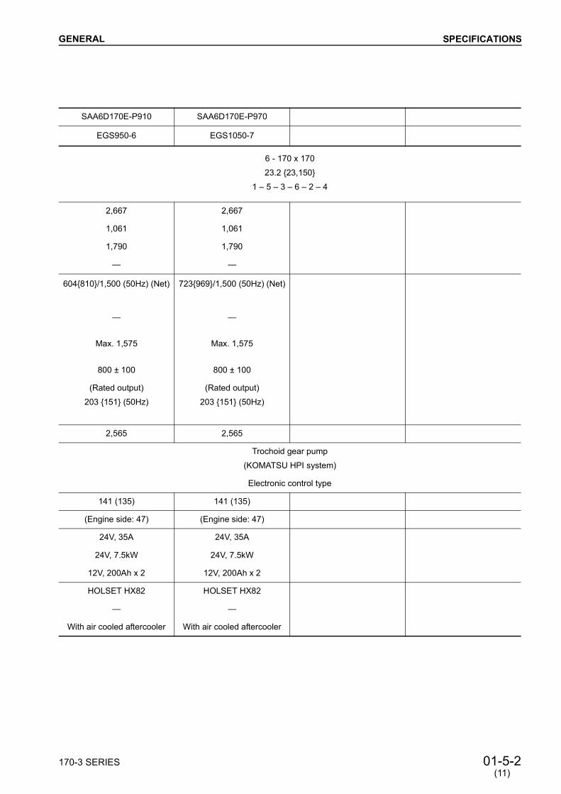
SAA6D170E-P910 SAA6D170E-P970
EGS950-6 EGS1050-7
6 - 170 x 170
23.2 23,150
1 5 3 6 2 4
2,667 2,667
1,061 1,061
1,790 1,790
604810/1,500 (50Hz) (Net) 723969/1,500 (50Hz) (Net)
Max. 1,575 Max. 1,575
800 ± 100 800 ± 100
(Rated output)
203 151 (50Hz)
(Rated output)
203 151 (50Hz)
2,565 2,565
Trochoid gear pump
(KOMATSU HPI system)
Electronic control type
141 (135) 141 (135)
(Engine side: 47) (Engine side: 47)
24V, 35A 24V, 35A
24V, 7.5kW 24V, 7.5kW
12V, 200Ah x 2 12V, 200Ah x 2
HOLSET HX82 HOLSET HX82
With air cooled aftercooler With air cooled aftercooler
(11)
SPECIFICATIONS

01-5-3 170-3 SERIES
GENERAL
OVERALL DRAWINGSA6D170E-3 VIEW FROM LEFT SIDE (D375A-5)
a. Center of crankshaft b. Rear face of flywheel housing
a The actual engine may be differentbecause of modifications.
OVERALL DRAWING
(11)

170-3 SERIES 01-5-4
GENERAL
SA6D170E-3 VIEW FROM RIGHT SIDE (D375A-5) a The actual engine may be differentbecause of modifications.
OVERALL DRAWING
(11)
01-5-5 170-3 SERIES
GENERAL
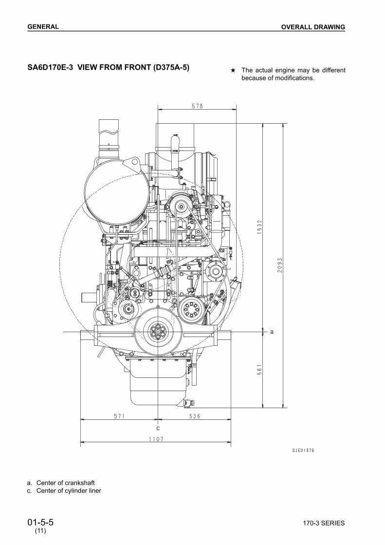
SA6D170E-3 VIEW FROM FRONT (D375A-5)
a. Center of crankshaft c. Center of cylinder liner
a The actual engine may be differentbecause of modifications.
OVERALL DRAWING
(11)

170-3 SERIES 01-5-6
GENERAL
SA6D170E-3 VIEW FROM REAR (D375A-5)
a. Center of crankshaft c. Center of cylinder liner
a The actual engine may be differentbecause of modifications.
OVERALL DRAWING
(11)


01-6 170-3 SERIES
GENERAL
SAA6D170E-3 VIEW FROM LEFT SIDE (WA600-3)
OVERALL DRAWING
a. Center of crankshaft b. Rear face of flywheel housing
a The actual engine may be differentbecause of modifications.
(9)

170-3 SERIES 01-7
GENERAL
SAA6D170E-3 VIEW FROM RIGHT SIDE (WA600-3)
a. Center of crankshaft b. Rear face of flywheel housing
OVERALL DRAWING
a The actual engine may be differentbecause of modifications.
(10)

01-8 170-3 SERIES
GENERAL
SAA6D170E-3 VIEW FROM FRONT (WA600-3)
a. Center of crankshaft b. Center of cylinder liner
OVERALL DRAWING
a The actual engine may be differentbecause of modifications.
(10)

170-3 SERIES 01-9
GENERAL
SAA6D170E-3 VIEW FROM REAR (WA600-3)
a. Center of crankshaft b. Center of cylinder liner
OVERALL DRAWING
a The actual engine may be differentbecause of modifications.
(10)

01-10 170-3 SERIES
GENERAL
SAA6D170E-3 VIEW FROM TOP (WA600-3)
a. Center of cylinder liner
OVERALL DRAWING
a The actual engine may be differentbecause of modifications.
(10)

170-3 SERIES 01-11
GENERAL
SAA6D170E-3 VIEW FROM LEFT SIDE (GENERATOR)
a. Center of crankshaft b. Rear face of flywheel housing
OVERALL DRAWING
a The actual engine may be differentbecause of modifications.
(10)
01-12 170-3 SERIES
GENERAL
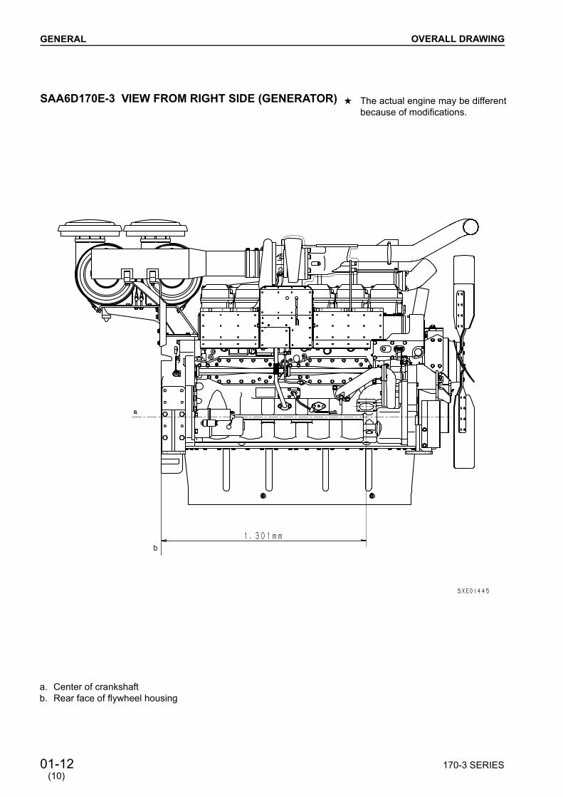
SAA6D170E-3 VIEW FROM RIGHT SIDE (GENERATOR)
a. Center of crankshaft b. Rear face of flywheel housing
OVERALL DRAWING
a The actual engine may be differentbecause of modifications.
(10)

170-3 SERIES 01-13
GENERAL
SAA6D170E-3 VIEW FROM FRONT (GENERATOR)
a. Center of crankshaft b. Center of cylinder liner
OVERALL DRAWING
a The actual engine may be differentbecause of modifications.
(10)

01-14 170-3 SERIES
GENERAL
SAA6D170E-3 VIEW FROM REAR (GENERATOR)
a. Center of crankshaft b. Center of cylinder liner
OVERALL DRAWING
a The actual engine may be differentbecause of modifications.
(10)

170-3 SERIES 01-15
GENERAL
SAA6D170E-3 VIEW FROM TOP (GENERATOR)
a. Center of cylinder liner
OVERALL DRAWING
a The actual engine may be differentbecause of modifications.
(10)

01-15-1 170-3 SERIES
GENERAL
SAA6D170E2-3 VIEW FROM LEFT SIDE (DCA-800SSK2, DENYO GENERATOR)
a. Center of crankshaft b. Rear face of flywheel housing
OVERALL DRAWING
a The actual engine may be differentbecause of modifications.
(10)

170-3 SERIES 01-15-2
GENERAL
SAA6D170E2-3 VIEW FROM RIGHT SIDE (DCA-800SSK2, DENYO GENERATOR)
a. Center of crankshaft b. Rear face of flywheel housing
OVERALL DRAWING
a The actual engine may be differentbecause of modifications.
(10)

01-15-3 170-3 SERIES
GENERAL
SAA6D170E2-3 VIEW FROM FRONT (DCA-800SSK2, DENYO GENERATOR)
a. Center of crankshaft b. Center of cylinder liner
OVERALL DRAWING
a The actual engine may be differentbecause of modifications.
(10)

170-3 SERIES 01-15-4
GENERAL
SAA6D170E2-3 VIEW FROM REAR (DCA-800SSK2, DENYO GENERATOR)
a. Center of crankshaft b. Center of cylinder liner
OVERALL DRAWING
a The actual engine may be differentbecause of modifications.
(10)

01-15-5 170-3 SERIES
GENERAL
SAA6D170E2-3 VIEW FROM TOP (DCA-800SSK2, DENYO GENERATOR)
a. Center of cylinder liner
OVERALL DRAWING
a The actual engine may be differentbecause of modifications.
(10)

01-16 170-3 SERIES
GENERAL
WEIGHT TABLEUnit: kg
No. Iteml Component SA6D170E-3 SAA6D170E-3 SAA6D170E2-3
1 Turbocharger
KTR110L 25 25
SCHWITZER S500 51 (Generator)
HOLSET 51
2 Cylinder head assembly Cylinder head, valve and valve spring 44 44 44
3 Cylinder block assembly Cylinder block, main bearing cap and cylinder liner 810 810 810
4 Gear case cover 42 42 42
5 Oil pan 45 105.1 66
6 Flywheel assembly FlywheelRing gear 34 (WA600-3) 141
7 Flywheel housing 93 (WA600-3) 134
8 Crankshaft assembly Crankshaft,crank gear (2 pcs.) 264 264 264
9 Camshaft assembly Camshaft, cam gear and thrust plate 70 70 70
10 piston and connecting rod assembly
Piston, piston ring, piston pin and connecting rod 21 21 21
11 Oil pump 10 10 10
12 Fuel pump 20 20 20
13 Water pump 16 16 16
14 Alternetor 11 (60A)12.5 (75A)
11 (60A)12.5 (75A) 8 (35A)
15 Starting motor 18 x 2 18 x 2 18 x 2
16 After cooler 40 40
17 Air compressor 15
WEIGHT TABLE
(10)
170-3 SERIES 01-17
GENERAL
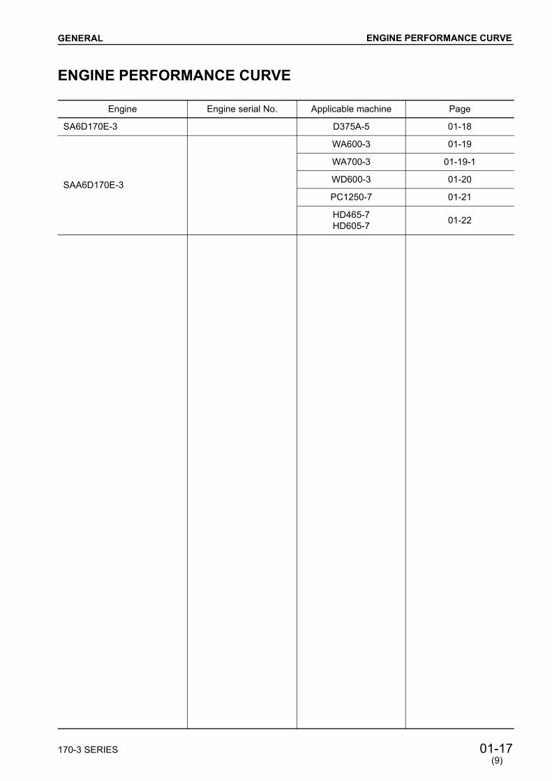
ENGINE PERFORMANCE CURVE
Engine Engine serial No. Applicable machine Page
SA6D170E-3 D375A-5 01-18
SAA6D170E-3
WA600-3 01-19
WA700-3 01-19-1
WD600-3 01-20
PC1250-7 01-21
HD465-7HD605-7 01-22
ENGINE PERFORMANCE CURVE
(9)

01-18 170-3 SERIES
GENERAL
SA6D170E-3 (D375A-5) Flywheel horsepower: 391 kW 524 HP /1,800 rpm (Net)Maximum torque : 2,650 Nm 270 kgm /1,300 rpm (Net)
ENGINE PERFORMANCE CURVE
(3)

170-3 SERIES 01-19
GENERAL
SAA6D170E-3 (WA600-3) Flywheel horsepower: 337 kW 452 HP /2,000 rpm (Net)Maximum torque : 2,120 Nm 216 kgm /1,400 rpm (Net)
ENGINE PERFORMANCE CURVE

01-19-1 170-3 SERIES
GENERAL ENGINE PERFORMANCE CURVE
SAA6D170E-3 (WA700-3) Flywheel horsepower: 478 kW 641 HP /2,000 rpm (Net)Maximum torque : 2,806 Nm 286 kgm /1,400 rpm (Net)
(9)

01-20 170-3 SERIES
GENERAL
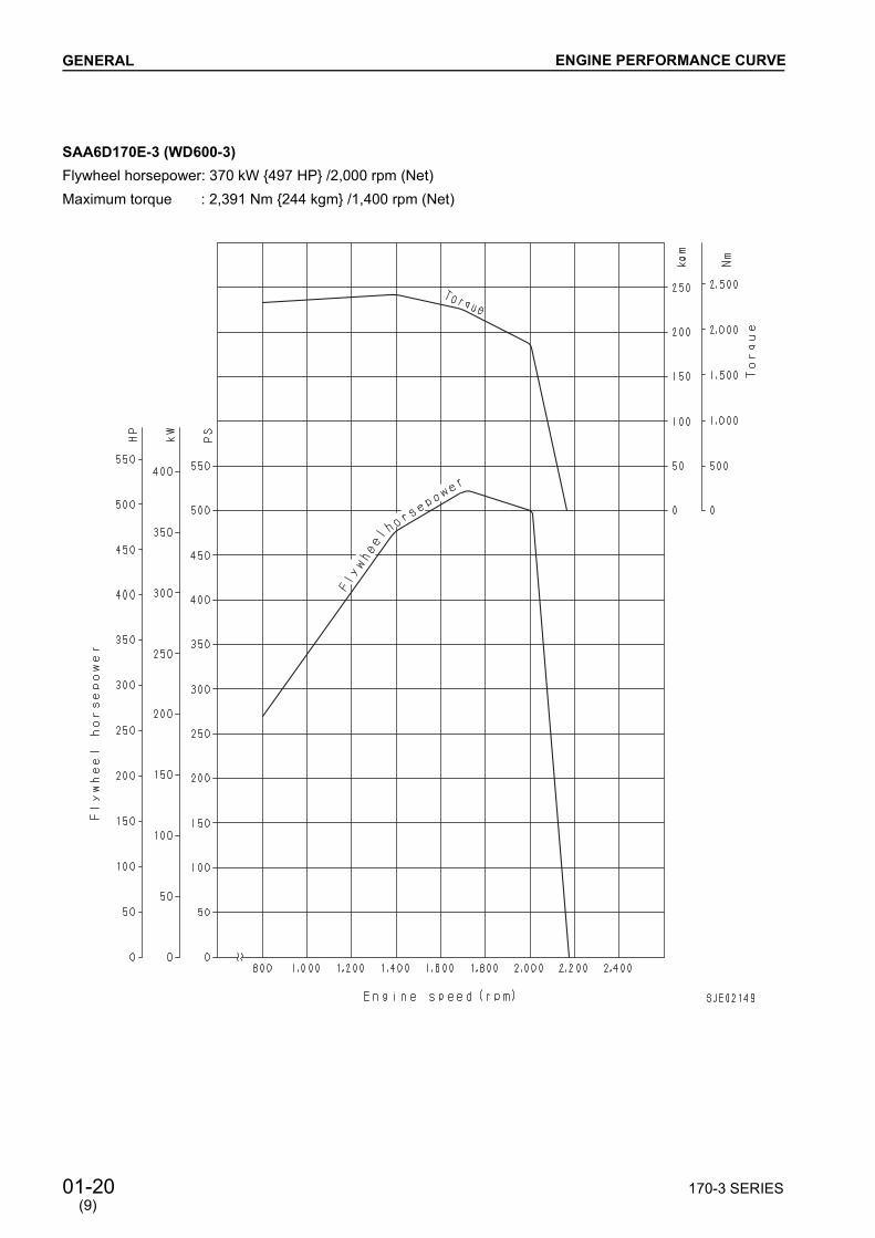
SAA6D170E-3 (WD600-3) Flywheel horsepower: 370 kW 497 HP /2,000 rpm (Net)Maximum torque : 2,391 Nm 244 kgm /1,400 rpm (Net)
ENGINE PERFORMANCE CURVE
(9)

170-3 SERIES 01-21
GENERAL
SAA6D170E-3 (PC1250-7) Flywheel horsepower: 485 kW 651 HP /1,800 rpm (Net)Maximum torque : 2,913 Nm 297 kgm /1,300 rpm (Net)
ENGINE PERFORMANCE CURVE
(9)
01-22 170-3 SERIES
GENERAL
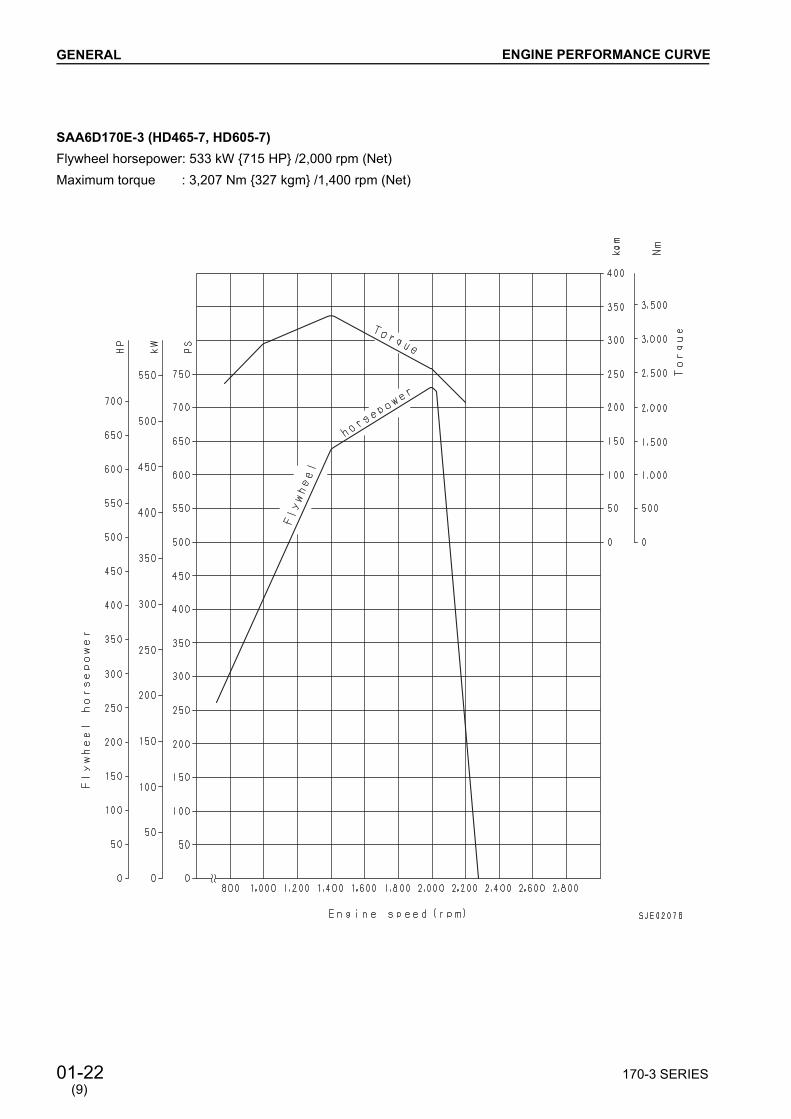
SAA6D170E-3 (HD465-7, HD605-7) Flywheel horsepower: 533 kW 715 HP /2,000 rpm (Net)Maximum torque : 3,207 Nm 327 kgm /1,400 rpm (Net)
ENGINE PERFORMANCE CURVE
(9)

11-2 170-3 SERIES
STRUCTURE AND FUNCTION
AIR CLEANERFTG TYPE (Generator)
AIR CLEANER
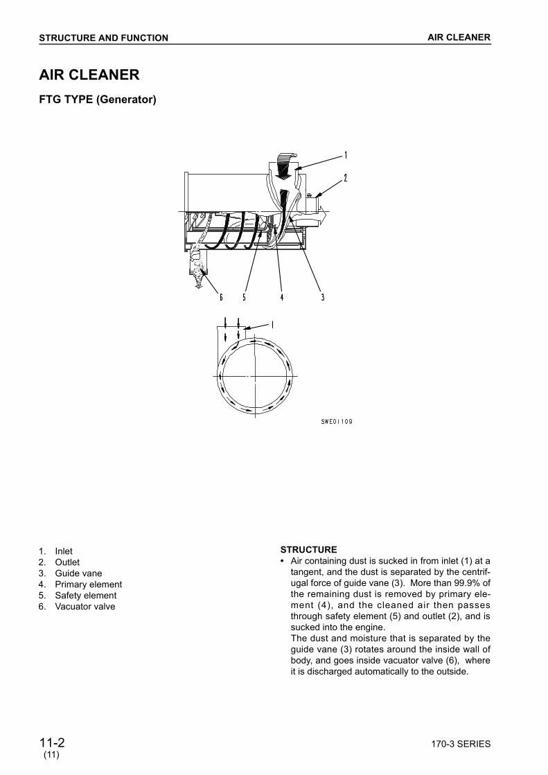
1. Inlet2. Outlet3. Guide vane4. Primary element5. Safety element6. Vacuator valve
STRUCTURE Air containing dust is sucked in from inlet (1) at a
tangent, and the dust is separated by the centrif-ugal force of guide vane (3). More than 99.9% ofthe remaining dust is removed by primary ele-ment (4), and the cleaned air then passesthrough safety element (5) and outlet (2), and issucked into the engine.The dust and moisture that is separated by theguide vane (3) rotates around the inside wall ofbody, and goes inside vacuator valve (6), whereit is discharged automatically to the outside.
(11)

170-3 SERIES 11-3
STRUCTURE AND FUNCTION AIR CLEANER
EGB TYPE (D375A-5, WA600-3, WA700-3, WD600-3, PC1250-7)(KOMA-CLONE MULTICYCLONE TYPE)
1. Inner element 2. Outer element 3. Check valve 4. Tube (34 pcs.) 5. Precleaner 6. Body of air cleaner A. Air inlet B. To turbocharger (sucked air) C. To muffler (dust)
(9)
a The actual engine may be differentbecause of modifications.
a The shape is subject to machinemodels.

11-3-1 170-3 SERIES
STRUCTURE AND FUNCTION AIR CLEANER
FRG TYPE (EGS950-6, EGS1050-7)[Air cleaner of cyclone poke type with evacuator valve (Radial seal type)]
(11)
a The actual engine may be differentbecause of modifications.
a The shape is subject to machinemodels.
1. Inner 2. Outer 3. Check vane 4. Primary element 5. Safety element 6. Evacuator valve 7. Dust pan 8. Guide plate (Sleeve) 9. Body10. Element

11-4 170-3 SERIES
STRUCTURE AND FUNCTION
TURBOCHARGERKTR110L (oil cooled type)
TURBOCHARGER
1. Blower housing 2. Center housing 3. Thrust nozzle 4. Turbine housing 5. Turbine impeller 6. Seal ring 7. Journal bearing 8. Turbing shaft 9. Thrust bearing10. Blower impeller
A. Air intake B. Air output C. Exhaust (inlet port) D. Exhaust (outlet port) E. Oil (inlet port) F. Oil (outlet port)
SPECIFICATIONSType: Komatsu KTR110L
(oil cooled type)Overall length: 308 mmOverall width: 305 mmOverall height: 287 mmWeight: 25 kg


170-3 SERIES 11-6-1
STRUCTURE AND FUNCTION
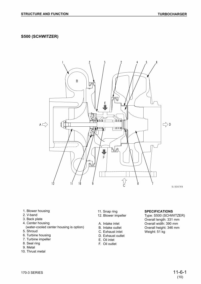
S500 (SCHWITZER)
1. Blower housing 2. V-band 3. Back plate 4. Center housing (water-cooled center housing is option) 5. Shroud 6. Turbine housing 7. Turbine impeller 8. Seal ring 9. Metal10. Thrust metal
11. Snap ring12. Blower impeller A. Intake inlet B. Intake outlet C. Exhaust inlet D. Exhaust outlet E. Oil inlet F. Oil outlet
TURBOCHARGER
SPECIFICATIONSType: S500 (SCHWITZER)Overall length: 331 mmOverall width: 390 mmOverall height: 346 mmWeight: 51 kg
(10)
11-6-2 170-3 SERIES
STRUCTURE AND FUNCTION
HOLSET
(10)
TURBOCHARGER
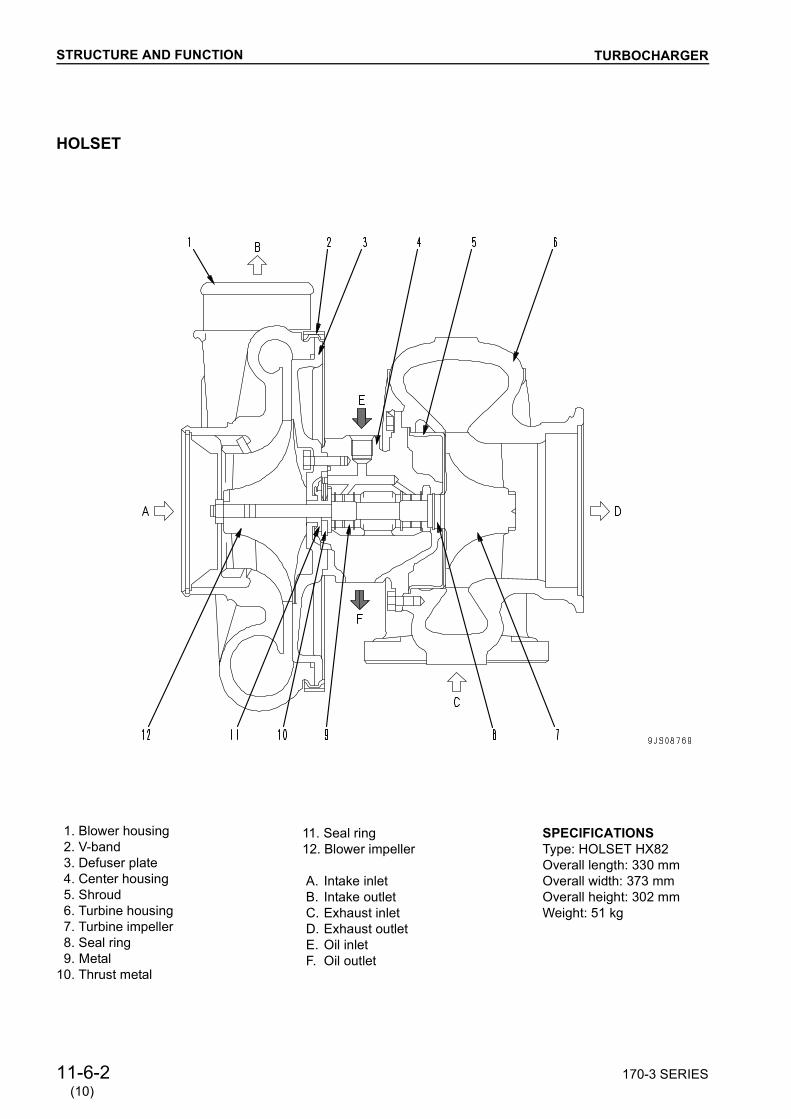
1. Blower housing 2. V-band 3. Defuser plate 4. Center housing 5. Shroud 6. Turbine housing 7. Turbine impeller 8. Seal ring 9. Metal10. Thrust metal
11. Seal ring12. Blower impeller A. Intake inlet B. Intake outlet C. Exhaust inlet D. Exhaust outlet E. Oil inlet F. Oil outlet
SPECIFICATIONSType: HOLSET HX82Overall length: 330 mmOverall width: 373 mmOverall height: 302 mmWeight: 51 kg

170-3 SERIES 11-7
STRUCTURE AND FUNCTION
AFTERCOOLERAIR-COOLED TYPESAA6D170E-3 (WA600-3)
AFTERCOOLER
a The specifications are subject to changeaccording to modification etc.
a The shape is subject to machine models.a The illustration shows the engine for
WA600-3.
1. Tank2. Side support3. Tube4. Fin
A. Intake air port(Turbocharger oi Intake manifold)
(9)

11-8 170-3 SERIES
STRUCTURE AND FUNCTION AFTERCOOLER
AIR-COOLED TYPESAA6D170E-3 (Generator)
a The specifications are subject to changeaccording to modification etc.
a The shape is subject to machine models.
1. Tank2. Side support3. Tube4. Fin
a. Intake air port(Turbocharger oi Intake manifold)
(9)


170-3 SERIES 11-21
STRUCTURE AND FUNCTION
No. 1 cylinder intake, exhaust side
SPECIFICATIONSCamshaft Special alloy steel forging, 7 bearings Journal surface, cam surface: Induction hardening
Valve timing (D375A-5, WA600-3, WA700-3, WD600-3, PC1250-7)
VALVE SYSTEM
No. 1 cylinder injector
Injector plunger timing
Valve timing (HD465-7, generator)
Camshaft part No.
Plunger lower-ing start angle
a
Plunger rise completion
angleb
6240-41-1210 BTDC53° BTDC109°
(9)

11-22 170-3 SERIES
STRUCTURE AND FUNCTION
LUBRICATION SYSTEM DIAGRAM
LUBRICATION SYSTEM DIAGRAME
1. Oil pan2. Oil level sensor3. Oil pump4. Regulator valve5. Oil cooler6. Thermo valve7. Oil filter
15. Auxiliary equipment drivegear (front side)
16. Oil pressure gauge17. Turbocharger
W. Cooling water
8. Safety valve 9. Main gallery10. Crankshaft11. Camshaft12. Rocker arm13. Piston cooling nozzle14. Timing gear (rear side)
a The actual engine may be differentbecause of modifications.


170-3 SERIES 11-47
STRUCTURE AND FUNCTION
TENSION PULLEY (D375A-5)
FAN, TENSION PULLEY
1. Tension shaft2. Spring3. Roller bearing4. Tension bracket5. Spacer
6. Tension pulley (outside diameter: 150 mm)7. Ball bearing8. Oil seal9. Grease nipple
a The actual engine may be differentbecause of modifications.
(2)

11-48 170-3 SERIES
STRUCTURE AND FUNCTION
FAN DRIVE (WA600-3, WA700-3, WD600-3, HD465-7, HD605-7)
FAN, TENSION PULLEY
1. Crankshaft pulley2. Fan belt3. Tension pulley4. Adjustment bolt5. Tension pulley bracket6. Fan pulley7. Fan
a. Direction of wind
Model Fanpulley
Crankshaft pulley
Tension pulley
Direction of wind from fan
WA600-3WD600-3 352 230 150 Blows out
WA700-3 380 204 150 Blows out
HD465-7HD605-7 365 220 150 Suck
Pulley outside diameter Unit: mm
(9)
a The actual engine may be differentbecause of modifications.

170-3 SERIES 11-49
STRUCTURE AND FUNCTION
TENSION PULLEY (WA600-3, WA700-3, WD600-3, PC1250-7, HD465-7, HD605-7)
FAN, TENSION PULLEY
(9)
1. Tension shaft2. Spring3. Roller bearing4. Tension bracket5. Spacer6. Tension pulley (outside diameter: 150 mm)
7. Ball bearing8. Oil seal9. Grease nipple
10. Grease nipple11. Adjustment bolt
a The actual engine may be differentbecause of modifications.
a The specifications may be differentfrom the following figure, dependingon the type of machine.

11-50 170-3 SERIES
STRUCTURE AND FUNCTION
ALTERNATORALTERNATOR MOUNTING (D375A-5)
ALTERNATOR
a The actual engine may be differentbecause of modifications.
1. Drive pulley (pulley outside diameter: 200 mm)2. Alternator pulley (pulley outside diameter: 85 mm)3. Alternator4. Alternator mounting bolt5. Adjustment bolt6. Locknut7. V-belt
(2)

170-3 SERIES 11-51
STRUCTURE AND FUNCTION
ALTERNATOR MOUNTING (WA600-3, WA700-3, WD600-3, PC1250-7, HD465-7, HD605-7)
ALTERNATOR
1. Drive pulley (pulley outside diameter: 182 mm)2. Alternator pulley (pulley outside diameter: 85 mm)3. Alternator4. Alternator mounting bolt5. Adjustment bolt6. Locknut7. V-belt
(9)
a The actual engine may be differentbecause of modifications.
a The specifications may be differentfrom the following figure, dependingon the type of machine.

11-52 170-3 SERIES
STRUCTURE AND FUNCTION
ALTERNATOR WITH BUILT-IN REGULATOR (OPEN TYPE, 60A)
Engine Machine model Type Specification Pulley diameter(mm)
Weight(kg)
SA6D170E-3 D375A-5(If equipped) Sawafuji Denki, open type 24V, 60A 85 11
a The actual engine may be differentbecause of modifications.
ALTERNATOR
(6)
1. Alternator 2. Alternator pulley 3. Terminal B4. Terminal R5. Terminal E
6. Internal electric circuit diagram 6A. Field coil 6B. Primary energized resistance6C. Regulator

170-3 SERIES 11-53
STRUCTURE AND FUNCTION
ALTERNATOR WITH BUILT-IN REGULATOR (OPEN TYPE, 75A)
ALTERNATOR
1. Alternator 2. Alternator pulley 3. Terminal B4. Terminal E5. Terminal R
Engine Machine model Type Specification Pulley diameter(mm)
Weight(kg)
SA6D170E-3 D375A-5(If equipped) Sawafuji Denki, open type 24V, 75A 85 12.5
SAA6D170E-3 WA600-3 WA700-3 WD600-3
Sawafuji Denki, open type 24V, 75A 85 12.5
a The actual engine may be differentbecause of modifications.
(9)
6. Internal electric circuit diagram 6A. Alternator 6B. Regulator

11-53-1 170-3 SERIES
STRUCTURE AND FUNCTION
ALTERNATOR WITH BUILT-IN REGULATOR (OPEN TYPE, 50)
ALTERNATOR
a The shape may differ according tothe machine model.
Engine Machine model Type Specification Pulley diameter
(mm)Weight
(kg)
SAA6D170E-3
PC1250-7 Nikko DenkiOpen type (brushless) 24V, 50A 85 11
HD465-7 Nikko DenkiOpen type (brushless) 24V, 50A 85 11
HD605-7 Nikko DenkiOpen type (brushless) 24V, 50A 85 11
(6)
1. Alternator 2. Alternator pulley 3. Terminal B4. Terminal R5. Terminal E
6. Internal electric circuit diagram 6A. Field coil6B. Primary energized resistance6C. Regulator


11-54 170-3 SERIES
STRUCTURE AND FUNCTION
STARTING MOTORFor 7.5 kW
STARTING MOTOR
1. Pinion gear 2. Starting motor assembly3. Magnetic switch4. Terminal B
Engine Machine model Type Specifi-
cationNo. of pinion teeth
Weight(kg)
Safety relay
mount-ing type
Con-nector type
SA6D170E-3 D375A-5 Nikko Denki(water-proof, oil-proof type)
27V, 7.5kWx2 11 18 G D
SAA6D170E-3
WA600-3WA700-3
Nikko Denki(water-proof, oil-proof type)
27V, 7.5kWx2 11 18 G C
WD600-3HD465-7HD605-7
Nikko Denki(water-proof, oil-proof type)
27V, 7.5kWx2 11 18 G D
a The actual engine may be differentbecause of modifications.
(9)
5. Terminal C6. External wiring diagram (2-pin connector type)
6A. Safety relay portion6B. Starting motor portion


170-3 SERIES 11-57
STRUCTURE AND FUNCTION
ELECTRICAL HEATER (SA6D170E-3)
1. Heater assembly2. Body3. Terrminal
SPECIFICATIONSHeater type: Coil heaterRated voltage: 22V (DC)Rated current: 36 A Capacity: 0.8 kW (0.4 kW x 2)
a The actual engine may be differentbecause of modifications.
STARTING AID
(9)

11-58 170-3 SERIES
STRUCTURE AND FUNCTION
ELECTRICAL HEATER (SAA6D170E-3)
(6)
a The actual engine may be differentbecause of modifications.
STARTING AID
1. Terminal2. Body3. Heater coil4. Connection diagram
SPECIFICATIONSHeater type: Electrical intake air heaterRated voltage: 22V (DC)Rated current: 111 A

170-3 SERIES 12-1
Standard value table for troubleshooting ................... 12- 2Standard value table for electrical parts .................... 12- 4Tools for testing, adjusting, and troubleshooting ....... 12- 6Measuring intake air pressure (boost pressure) ........ 12- 7Measuring exhaust temperature (overall engine)...... 12- 7Troubleshooting for injector ....................................... 12- 8Adjusting valve clearance.......................................... 12- 9Adjusting injector set load ......................................... 12-10Measuring compression pressure ..............................12-11Measuring blow-by pressure .................................... 12-12Measuring oil pressure .............................................. 12-13Handling equipment in fuel circuit ............................. 12-13Measuring fuel circuit pressure ................................. 12-14Visual inspection of return fuel .................................. 12-15Bleeding air from fuel circuit ...................................... 12-16Adjusting speed sensor ............................................. 12-17Replacing and adjusting fan belt ............................... 12-18Testing and adjusting alternator belt tension ............. 12-20Precautions when operating engine asan individual part ....................................................... 12-21Arrangement of control devices and electric circuit diagram for HPI ......................................................... 12-22Run-in standard......................................................... 12-25Performance test standards ...................................... 12-26Troubleshooting....................................................... 12-101
12 TESTING AND ADJUSTING
➅

12-2 170-3 SERIES
TESTING AND ADJUSTING
STANDARD VALUE TABLE FOR TROUBLESHOOTING
a This STANDARD VALUE TABLE does not give the standard values for adjusting the engine output. a Do not use the values in this table to change the adjusting the ECVA or injector.
Engine SAA6D170E-3
Model D375A-5
Cate-gory Item Measurement conditions Unit Standard value
for new machineService limit
value
Per
for-
man
ce Engine speed High idling Low idling
rpmrpm
2,000±40 750
2,000±40 750
Speed needed to start 0°C (without starting aid) -20°C (with starting aid)
rpmrpm
Min. 130Min. 100
Inta
ke, e
xhau
st s
yste
m
Intake resistance
Air supply pressure
Exhaust pressure
Exhaust temperature
Whole speed range
At rated output
At rated output
Whole speed range (20°C)
kPammH2O
kPammH2O
kPammH2O
°C
Max. 3Max. 300Min. 126.7Min.950Min. 106.7Min. 800Min 650
7.5762113.385096.0720700
Exhaust gas colorAt sudden acceleration(low idling o high idling) At rated output
Bosch index
Max. 4.5Max. 1.0Max. 0.5
5.52.01.5
Valve clearance Intake valve Exhaust valve
mmmm
0.320.62
Eng
ine
prop
er
Compression pressureOil temperature: 40 60°C (engine speed:
210 250 rpm)MPakg/cm2 Min. 2.9
Min. 302.121
Blow-by pressureAt rated output(water temperature:
Min. 70°C)kPammH2O Max. 3.9
Max. 4007.9
800
Lubr
icat
ion
syst
em Oil pressure
(oil temperature:Min. 80°C)
At rated outputSAE30 or SAE15W-40
SAE10W
At low idling SAE30 or SAE15W-40
SAE10W
MPakg/cm2
MPakg/cm2
MPakg/cm2
MPakg/cm2
0.39 0.544.0 5.50.34 0.493.5 5.0
Min. 0.12Min. 1.2Min. 0.10Min. 1.0
0.212.10.181.8
0.080.80.070.7
Oil temperature Whole speed range(inside oil pan) °C 90 110 120
Oil consumption Ratio to fuel consumption at continuous rated output % Max. 0.5 1.0
Coo
ling
syst
em
Radiator pressure valve function
Cracking pressure(differential pressure) kPakg/cm2
Fan speed At rated speed rpm 1,125±35 1,125±35
Fan belt tensionDeflection when pressed with finger force of approx. 58.8 N 6 kg
mm Auto-tension
Alternator belt tensionDeflection when pressed with finger force of approx. 98 N 10 kg
mm 10 15
+50 0
+50 0
STANDARD VALUE TABLE FOR TROUBLESHOOTING
(10)

170-3 SERIES 12-3
TESTING AND ADJUSTING
SAA6D170E-3
WA600-3 WA700-3 Generator(50HZ specification)
Standard value for new machine
Service limit value
Standard value for new machine
Service limit value
Standard value for new machine
Service limit value
2,170±30700±25
2,170±30700±25
2,240±30725±25
2,170±30700±25
Max. 1,575800±100
Max. 1,575800±100
Min. 130Min. 100
Min. 130Min. 100
Min. 130Min. 100
Min. 130Min. 100
Min. 130Min. 100
Min. 130Min. 100
Max. 3Max. 300Min. 126.7Min.950Min. 106.7Min. 800Min. 650
7.5762113.385096.0720700
Max. 3Max. 300Min. 126.7Min.950Min. 106.7Min. 800Min. 650
7.5762113.385096.0720700
Max. 3Max. 300Min. 126.7Min.950Min. 106.7Min. 800Min. 650
7.5762113.385096.0720700
Max. 4.5Max. 1.0Max. 0.5
5.52.01.5
Max. 4.5Max. 1.0Max. 0.5
5.52.01.5
Max. 1.0Max. 0.8
2.02.0
0.320.62
0.320.62
0.320.62
Min. 2.9Min. 30
2.121
Min. 2.9Min. 30
2.121
Min. 2.9Min. 30
2.121
Max. 3.9Max. 400
7.9800
Max. 3.9Max. 400
7.9800
6.4650
9.81,000
0.39 0.544.0 5.50.34 0.493.5 5.0
Min. 0.12Min. 1.2Min. 0.10Min. 1.0
0.212.10.181.8
0.080.80.070.7
0.39 0.544.0 5.50.34 0.493.5 5.0
Min. 0.12Min. 1.2Min. 0.10Min. 1.0
0.212.10.181.8
0.080.80.070.7
0.39 0.544.0 5.50.34 0.493.5 5.0
Min. 0.12Min. 1.2Min. 0.10Min. 1.0
0.212.10.181.8
0.080.80.070.7
90 110 120 90 110 120 90 110 120
Max. 0.5 1.0 Max. 0.5 1.0 Max. 0.4 1.0
700.7
1,150±35 1,150±35 1,070±35 1,070±35 960±30 960±30
Semi auto-ten-sion Semi auto-ten-
sion 3 3
10 15 10 15 10 15 10 15
STANDARD VALUE TABLE FOR TROUBLESHOOTING
(10)

12-3-1 170-3 SERIES
TESTING AND ADJUSTING
a This STANDARD VALUE TABLE does not give the standard values for adjusting the engine output. a Do not use the values in this table to change the adjusting the ECVA or injector.
Engine SAA6D170E-3
Model Generator(60HZ specification)
Cate-gory Item Measurement conditions Unit Standard value
for new machine Service limit
value
Per
for-
man
ce Engine speed High idling Low idling
rpmrpm
Max. 1,890800±100
Max. 1,890800±100
Speed needed to start 0°C (without starting aid) -20°C (with starting aid)
rpmrpm
Min. 130Min. 100
Min. 130Min. 100
Inta
ke, e
xhau
st s
yste
m
Intake resistance
Air supply pressure
Exhaust pressure
Exhaust temperature
Whole speed range
At rated output
At rated output
Whole speed range (20°C)
kPammH2O
kPammHg
kPammHg
°C
Max. 3Max. 300Min. 126.7Min.950Min. 106.7Min. 800Min. 650
7.5762113.385096.0720700
Exhaust gas colorAt sudden acceleration(low idling o high idling) At rated output
Bosch index
Max. 1.0Max. 0.8
2.02.0
Valve clearance Intake valve Exhaust valve
mmmm
0.320.62
Eng
ine
prop
er
Compression pressureOil temperature: 40 60°C (engine speed:
210 250 rpm)MPakg/cm2 Min. 2.9
Min. 302.121
Blow-by pressureAt rated output(water temperature:
Min. 70°C)kPammH2O 6.4
6509.8
1,000
Lubr
icat
ion
syst
em Oil pressure
(oil temperature:Min. 80°C)
At rated outputSAE30 or SAE15W-40
SAE10W
At low idling SAE30 or SAE15W-40
SAE10W
MPakg/cm2
MPakg/cm2
MPakg/cm2
MPakg/cm2
0.39 0.544.0 5.50.34 0.493.5 5.0
Min. 0.12Min. 1.2Min. 0.10Min. 1.0
0.212.10.181.8
0.080.80.070.7
Oil temperature Whole speed range(inside oil pan) °C 90 110 120
Oil consumption Ratio to fuel consumption at continuous rated output % Max. 0.4 1.0
Coo
ling
syst
em
Radiator pressure valve function
Cracking pressure(differential pressure) kPakg/cm2 700.7
Fan speed At rated speed rpm 1,150±35 1,150±35
Fan belt tensionDeflection when pressed with finger force of approx. 58.8 N 6 kg
mm 3 3
Alternator belt tensionDeflection when pressed with finger force of approx. 98 N 10 kg
mm
STANDARD VALUE TABLE FOR TROUBLESHOOTING
(11)

170-3 SERIES 12-3-2
TESTING AND ADJUSTING
SAA6D170E-3 SAA6D170E2-3 SAA6D170E-P910
WD600-3 DCA-800SSK2 (DENYO GENERATOR) EGS950-6
Standard value for new machine
Service limit value
Standard value for new machine
Service limit value
Standard value for new machine
Service limit value
2,190±30700±25
2,190±30700±25
Max. 1,890875±25
Max. 1,890875±25
Max. 1,575800±100
Max. 1,575800±100
Min. 130Min. 100
Min. 130Min. 100
Min. 130Min. 100
Min. 130Min. 100
Min. 130Min. 100
Max. 3Max. 300Min. 126.7Min.950Min. 106.7Min. 800Min. 650
7.5762113.385096.0720700
Max. 3.7Max. 380Min. 126.7Min.950Min. 106.7Min. 800Min. 650
7.5762113.385096.0720700
Max. 3Max. 300Min. 126.7Min.950Min. 106.7Min. 800Min. 690
7.5762113.385096.0720750
Max. 4.5Max. 1.0Max. 0.5
5.52.01.5
Max. 1.0Max. 0.8
2.02.0
Max. 1.0Max. 0.8
2.02.0
0.320.62
0.320.62
0.320.62
Min. 2.9Min. 30
2.121
Min. 2.9Min. 30
2.121
Min. 2.9Min. 30
2.121
Max. 3.9Max. 400
7.9800
Max. 6.4Max. 650
9.81,000
Max. 6.4Max. 650
9.81,000
0.39 0.544.0 5.50.34 0.493.5 5.0
Min. 0.12Min. 1.2Min. 0.10Min. 1.0
0.212.10.181.8
0.080.80.070.7
0.39 0.544.0 5.50.34 0.493.5 5.0
Min. 0.12Min. 1.2Min. 0.10Min. 1.0
0.212.10.181.8
0.080.80.070.7
0.39 0.544.0 5.50.34 0.493.5 5.0
Min. 0.12Min. 1.2Min. 0.10Min. 1.0
0.212.10.181.8
0.080.80.070.7
90 110 120 90 110 120 90 110 120
Max. 0.5 1.0 Max. 1.5 2.5 Max. 0.4 1.0
70 0.7 70 0.7
1,080±35 1,080±35 1,150±35 1,150±35 960±30 960±30
Semi auto-ten-sion 3 3 3 3
10 15 10 15 10 15 10 15
(11)
STANDARD VALUE TABLE FOR TROUBLESHOOTING
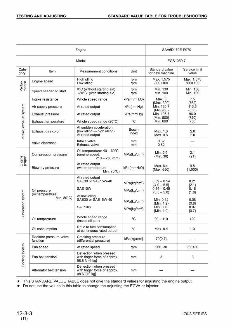
12-3-3 170-3 SERIES
TESTING AND ADJUSTING
(11)
a This STANDARD VALUE TABLE does not give the standard values for adjusting the engine output. a Do not use the values in this table to change the adjusting the ECVA or injector.
Engine SAA6D170E-P970
Model EGS1050-7
Cate-gory Item Measurement conditions Unit Standard value
for new machine Service limit
value
Per
for-
man
ce Engine speed High idling Low idling
rpmrpm
Max. 1,575800±100
Max. 1,575800±100
Speed needed to start 0°C (without starting aid) -20°C (with starting aid)
rpmrpm
Min. 130Min. 100
Min. 130Min. 100
Inta
ke, e
xhau
st s
yste
m
Intake resistance
Air supply pressure
Exhaust pressure
Exhaust temperature
Whole speed range
At rated output
At rated output
Whole speed range (20°C)
kPammH2O
kPammHg
kPammHg
°C
Max. 3Max. 300Min. 126.7Min.950Min. 106.7Min. 800Min. 690
7.5762113.385096.0720750
Exhaust gas colorAt sudden acceleration(low idling o high idling) At rated output
Bosch index
Max. 1.0Max. 0.8
2.02.0
Valve clearance Intake valve Exhaust valve
mmmm
0.320.62
Eng
ine
prop
er
Compression pressureOil temperature: 40 60°C (engine speed:
210 250 rpm)MPakg/cm2 Min. 2.9
Min. 302.121
Blow-by pressureAt rated output(water temperature:
Min. 70°C)kPammH2O Max. 6.4
Max. 6509.8
1,000
Lubr
icat
ion
syst
em Oil pressure
(oil temperature:Min. 80°C)
At rated outputSAE30 or SAE15W-40
SAE10W
At low idling SAE30 or SAE15W-40
SAE10W
MPakg/cm2
MPakg/cm2
MPakg/cm2
MPakg/cm2
0.39 0.544.0 5.50.34 0.493.5 5.0
Min. 0.12Min. 1.2Min. 0.10Min. 1.0
0.212.10.181.8
0.080.80.070.7
Oil temperature Whole speed range(inside oil pan) °C 90 110 120
Oil consumption Ratio to fuel consumption at continuous rated output % Max. 0.4 1.0
Coo
ling
syst
em
Radiator pressure valve function
Cracking pressure(differential pressure) kPakg/cm2 700.7
Fan speed At rated speed rpm 960±30 960±30
Fan belt tensionDeflection when pressed with finger force of approx. 58.8 N 6 kg
mm 3 3
Alternator belt tensionDeflection when pressed with finger force of approx. 98 N 10 kg
mm
STANDARD VALUE TABLE FOR TROUBLESHOOTING

12-4 170-3 SERIES
TESTING AND ADJUSTING
STANDARD VALUE TABLE FOR ELECTRICAL PARTS
Component Name
Connec-tor No.
Inspec-tion
MethodCriteria Measurement
conditions
Atmospheric pressure sensor
AAPS/AAPR
Mea
sure
men
t of v
olta
ge
If the condition is within the range shown in the table below, it is normal.
1) Connect T-adapter to connector.
2) Turn starting switch ON.
Boost pressure sensor IMPR
Mea
sure
men
t of v
olta
ge If the condition is within the range shown in the table below,
it is normal.1) Connect T-adapter
to connector. 2) Turn starting switch
ON.
Intake manifold temperature sensor
IMTS
Mea
sure
men
t of r
esis
tanc
e
If the condition is within the range shown in the table below, it is normal.
1) Turn starting switch OFF.
2) Disconnect connec-tor.
Intake manifold temperature sensor (For generator)
IMTS
Mea
sure
men
t of r
esis
tanc
e
If the condition is within the range shown in the table below, it is normal.
1) Turn starting switch OFF.
2) Disconnect connec-tor.
Pin Height Atmospheric pres-sure Voltage
Between (A) (B) 4.75 5.25 V
Between (C) (B)
0 m 101.0 kPa760 mmHg 4.42 ± 0.12 V
1,000 m 89.9 kPa674 mmHg 3.97 ± 0.12 V
2,000 m 79.5 kPa596 mmHg 3.57 ± 0.12 V
3,000 m 70.1 kPa526 mmHg 3.21 ± 0.12 V
4,000 m 61.6 kPa462 mmHg 2.88 ± 0.12 V
Pin Boost pressure VoltageBetween (A) (B) 4.75 5.25 V
Between (C) (B)
0 kPa0 mmHg 0.5 ± 0.03 V
345 kPa2,590 mmHg 4.5 ± 0.08 V
Pin Intake manifold temperature Resistance
Between (A) (B)
0°C 30k 36kz 25°C 9k 11kz 50°C 3k 4kz 75°C 1,350 1,500z100°C 600 675z
Between (A), (B) ground Min. 1 Mz
Pin Intake manifold temperature Resistance
Between (A) (B)
0°C 10k 13kz 25°C 3k 5kz 50°C 1k 2kz 80°C 6,200 7,500z100°C 3,500 4,500z
Between (A), (B) ground Min. 1 Mz
STANDARD VALUE TABLE FOR ELECTRICAL PARTS
(10)

170-3 SERIES 12-5
TESTING AND ADJUSTING
Component Name
Connec-tor No.
Inspec-tion
MethodCriteria Measurement
conditions
Oil pressure sensor OPS
Mea
sure
men
t of v
olta
ge If the condition is within the range shown in the table below,
it is normal.1) Connect T-adapter
to connector. 2) Turn starting switch
ON.
Fuel temperature sensor
FTS/FLTP
Mea
sure
men
t of r
esis
tanc
e
If the condition is within the range shown in the table below, it is normal.
1) Turn starting switch OFF.
2) Disconnect connec-tor.
Water temperature sensor
CTS/CLTP
Mea
sure
men
t of r
esis
tanc
e
If the condition is within the range shown in the table below, it is normal.
1) Turn starting switch OFF.
2) Disconnect connec-tor.
Engine speed sensor SP1SP2
Mea
sure
men
tof
resi
stan
ce
If the condition is within the range shown in the table below, it is normal.
1) Turn starting switch OFF.
2) Disconnect connec-tor.
Fuel pump pressure sensor PMPR
Mea
sure
men
t of v
olta
ge If the condition is within the range shown in the table below,
it is normal.1) Connect T-adapter
to connector.2) Turn starting switch
ON.
Pin Oil pressure VoltageBetween (A) (B) 4.75 5.25 V
Between (C) (B)
0 kPa0 mmHg 0.5 ± 0.08 V
689 kPa7.03 mmHg 4.5 ± 0.08 V
Pin Intake manifold temperature Resistance
Between (A) (B)
0°C 30k 36kz 25°C 9k 11kz 50°C 3k 4kz 75°C 1,350 1,500z100°C 600 675z
Between (A), (B) ground Min. 1 Mz
Pin Watertemperature Resistance
Between (A) (B)
0°C 30k 36kz 25°C 9k 11kz 50°C 3k 4kz 75°C 1,350 1,500z100°C 600 675z
Between (A), (B) ground Min. 1 Mz
Pin ResistanceBetween (A) (B) 1,000 2,000 zBetween (A), (B) ground Min. 1 Mz
Pin Fuel pressure VoltageBetween (A) (B) 4.75 5.25 V
Between (C) (B)
0 kPa0 kg/cm2 0.5 ± 0.04 V
2,582 kPa26.33 kg/cm2 4.5 ± 0.06 V
(10)
STANDARD VALUE TABLE FOR ELECTRICAL PARTS

12-5-1 170-3 SERIES
TESTING AND ADJUSTING
Component Name
Connec-tor No.
Inspec-tion
MethodCriteria Measurement
conditions
Fuel rail pressure sensor RPR
Mea
sure
men
t of v
olta
ge If the condition is within the range shown in the table below,
it is normal.1) Connect T-adapter
to connector.2) Turn starting switch
ON.
Timing rail pressure sensor TPR
Mea
sure
men
t of v
olta
gee If the condition is within the range shown in the table below,
it is normal.1) Connect T-adapter
to connector.2) Turn starting switch
ON.
Fuel pump actuator
FTS/FLTP
Mea
sure
men
tof
resi
stan
ce
If the condition is within the range shown in the table below, it is normal.
1) Turn starting switch OFF.
2) Disconnect connec-tor.
Fuel shut-off valve
FSO+FSO-
Mea
sure
men
tof
resi
stan
ce
If the condition is within the range shown in the table below, it is normal.
1) Turn starting switch OFF.
2) Disconnect connec-tor.
Fuel rail actuator RAIL
Mea
sure
men
tof
resi
stan
ce If the condition is within the range shown in the table below,
it is normal.1) Turn starting switch
OFF.2) Disconnect connec-
tor.
Timing rail actuator TIMG
Mea
sure
men
tof
resi
stan
ce
If the condition is within the range shown in the table below, it is normal.
1) Turn starting switch OFF.
2) Disconnect connec-tor.
Pin Fuel pressure VoltageBetween (A) (B) 4.75 5.25 V
Between (C) (B)
103 kPa10.5 kg/cm2 0.5 ± 0.04 V
1,722 kPa17.56 kg/cm2 4.5 ± 0.06 V
Pin Fuel pressure VoltageBetween (A) (B) 4.75 5.25 V
Between (C) (B)
0 kPa0 kg/cm2 0.5 ± 0.04 V
2,582 kPa26.33 kg/cm2 4.5 ± 0.06 V
Pin ResistanceBetween (A) (C) 7 9 ΩBetween (A), (C) ground Min. 1 MΩ
Pin ResistanceBetween FSO+ FSO- 23 40 ΩBetween FSO+, FSO- ground Min. 1 MΩ
Pin ResistanceBetween (A) (C) 7 9 ΩBetween (A), (C) ground Min. 1 MΩ
Pin ResistanceBetween (A) (C) 7 9 ΩBetween (A), (C) ground Min. 1 MΩ
(10)
STANDARD VALUE TABLE FOR ELECTRICAL PARTS

12-6 170-3 SERIES
TESTING AND ADJUSTING
TOOLS FOR TESTING, ADJUSTING, AND TROUBLESHOOTING
Check, measurement item
Sym-bol
Troubleshooting tool Part Number Remarks
Intake resistance
A Pressure test kit 799-203-2002
- 9.8 – 0 kPa- 1,000 – 0 mmH2O
Intake pressure 0 – 200 kPa0 – 1,500 mmH2O
Exhaust pressure 0 – 200 kPa0 – 1,500 mmH2O
Blow-by pressure 0 – 9.8 kPa0 – 1,000 mmH2O
Lubricant pressure 0 – 1.0 MPa0 – 10 kg/cm2
Fuel pressure B
1 Adapter 795-799-5550 For measuring fuel pressure
2 Hose 799-101-5150
3 Oil pressure gauge 795-799-5560 -0.1 – 0 MPa-1.0 – 0 kg/cm2
4 Oil pressure gauge 799-101-5140 2.5 MPa25 kg/cm2
Intake temperature, exhaust temperature
C Digital temperature gauge 799-101-1502 -99.9 – 1,299°COil temperature, water temperature
Troubleshooting for injector D Heat gun
(surface temperature gauge) 795-799-5510 For carry out troubleshooting of injector
Exhaust color EHandy smoke tester 799-201-9000
Smoke meter Commercially available
Compression pressure F
1 Gauge assembly 795-502-1590 6.9 MPa70kg/cm2
2
Adapter 795-611-1210 For 170-3 engine
O-ring 6560-11-8410
O-ring 6560-11-8310
O-ring 6560-11-8210
O-ring 6560-11-8510
Gasket 6560-11-7310
Valve clearance GBarring device 6162-23-4500
Feeler gauge Commercially available
Intake: 0.32 mm,Exhaust: 0.62 mm
Specific gravity of battery electrolyte
H Battery, coolant tester795-501-1001 Temperature: –5 to – 50°C
Coolant freezing temperature 799-202-9001 Specific gravity: 1,100 – 1,300
Pressure valve functionJ Radiator cap tester 799-202-9001 0 – 0.2 MPa0 – 2 kg/cm2
Leakage from cooling system
Quality of coolant K Water tester 799-202-7002 PH, nitrous acid ion density
TOOLS FOR TESTING, ADJUSTING,AND TROUBLESHOOTING
➄

170-3 SERIES 12-6-1
TESTING AND ADJUSTING
Check, measurement item
Sym-bol Troubleshooting tool Part Number Remarks
Electrical components, wiring harnesses L
1 Wiring harness checker 799-601-9000 T-adapter for HD30 and DT, box
2 Socket (S) 795-799-5520 For speed sensor
3 Socket (C) 795-799-5530 For intake air temperature sensorFor coolant temperature sensor
4 Socket (A) 795-799-5540 For fuel temperature sensor
5 Cable795-799-5540(cummins No.
3824774)Atmospheric pressureFuel rail pressure sensorTiming rail pressure sensorFuel pump actuatorFuel rail actuatorTiming rail actuatorEngine oil pressure sensorBoost pressure sensorFuel pump pressure sensor
6 Cable795-799-5470(cummins No.
3824775)
7 Cable795-799-5480(cummins No.
3824776)
➄
TOOLS FOR TESTING, ADJUSTING,AND TROUBLESHOOTING

170-3 SERIES 12-7
TESTING AND ADJUSTING
MEASURING INTAKE AIR PRESSURE(BOOST PRESSURE)
When installing or removing the measuringequipment, be careful not to touch high-temper-ature parts.
1. Remove air intake pressure measurement plug(1).
2. Install the nipple and hose ➀ of pressure test kitA and connect the hose to pressure test kit A.
3. Start the engine and measure the intake air pres-sure (boost pressure) when the engine is runningat rated horsepower. When measuring with the engine mounted
on the machine, measure according to theconditions given in the shop manual for themachine.
4. After completing the measurement, remove themeasurement equipment and set to the originalcondition.
MEASURING EXHAUST TEMPERATURE(OVERALL ENGINE)
Wait for the exhaust manifold temperature to godown before removing or installing the measur-ing equipment.
1. Remove exhaust temperature measurementplug (1). Since the exhaust manifolds of cylinders No.
1 – 3 and those of cylinders No. 4 – 6 areindependent from each other, measure theexhaust temperature at both plugs.
2. Fit the sensor ➀ of digital temperature gauge C,then connect to the digital temperature gauge B.
3. Start the engine and measure the intake air pres-sure (boost pressure) when the engine is runningat rated horsepower. When measuring with the engine mounted
on the machine, measure according to theconditions given in the shop manual for themachine.
4. After completing the measurement, remove themeasurement equipment and set to the originalcondition.
➃
MEASURING INTAKE AIR PRESSURE (BOOST PRESSURE),MEASURING EXHAUST TEMPERATURE (OVERALL ENGINE)

12-8 170-3 SERIES
TESTING AND ADJUSTING
TROUBLESHOOTING FOR INJECTOR If the torque converter stall speed or the hydrau-
lic pump relief speed is low and bad combustionseems to be caused by defective fuel injection,perform troubleshooting for the injector accord-ing to the following procedure.
1. Stop the engine and wait for it to cool down. A guideline for judging if the engine has
cooled down is that the temperature of theexhaust manifold is less than 20°C above theambient temperature.
2. Make measurement marks a to the exhaustmanifold outlets of the all cylinders. Make the marks at the same points of the
tops or bottoms of the exhaust manifolds ofthe all cylinders.
3. Using heat gun D, measure the temperature atthe exhaust manifold outlet port of each cylinderbefore starting the engine. Apply the measurement light (center) of the
heat gun to mark a of each cylinder to pre-vent dispersion of the measurement resultscaused by difference of the measuringpoints.
4. Run the engine at low idling speed.
5. Using heat gun D, measure the temperature atthe exhaust manifold outlet port of each cylinder3 minutes, 6 minutes, 9 minutes, and 12 minutesafter starting the engine. Apply the measurement light (center) of the
heat gun to mark a of each cylinder to pre-vent dispersion of the measurement resultscaused by difference of the measuringpoints.
6. Compensate the measured value for each cylin-der 12 minutes after starting the engine andjudge if there is any cylinder with a problem. Compensation value
Unit:°C
Method of judgementAfter compensating, add up the values forthe exhaust gas temperature and calculatethe average value. Any cylinder that is morethan 20ºC lower than the average value canbe considered abnormal.
Measurement and judgement example 1No. 2 cylinder is more than 20°C lower thanthe average value, so judge it as abnormal.
Unit:°C
Measurement and judgement example 2No. 3 cylinder is more than 20°C lower thanthe average value, so judge it as abnormal.
Unit:°C
Measurement and judgement example 3No cylinder is more than 20°C lower than theaverage value, so judge all cylinders as nor-mal.
Unit:°C
Cylinder No. 1 No. 2 No. 3 No. 4 No. 5 No. 6Compensation
value +20 +5 0 0 +5 +20
Cylinder No. 1 No. 2 No. 3 No. 4 No. 5 No. 6Measured value 85 62 79 112 89 82Compensated
value 105 67 79 112 94 102
Average value 93
Cylinder No. 1 No. 2 No. 3 No. 4 No. 5 No. 6Measured value 86 96 73 91 94 103Compensated
value 106 101 73 91 99 123
Average value 99
Cylinder No. 1 No. 2 No. 3 No. 4 No. 5 No. 6Measured value 70 88 88 93 86 72Compensated
value 90 93 88 93 91 92
Average value 91
TROUBLESHOOTING FOR INJECTOR
➄
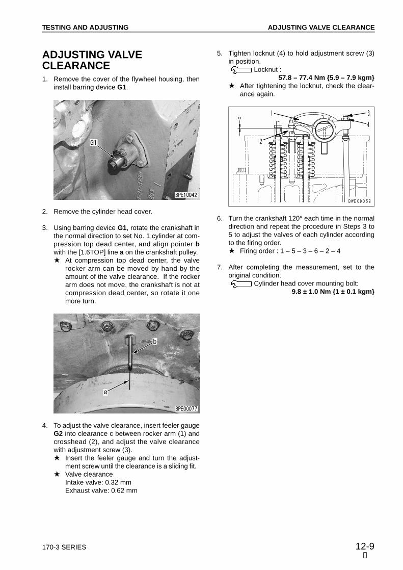
170-3 SERIES 12-9
TESTING AND ADJUSTING
ADJUSTING VALVE CLEARANCE 1. Remove the cover of the flywheel housing, then
install barring device G1.
2. Remove the cylinder head cover.
3. Using barring device G1, rotate the crankshaft inthe normal direction to set No. 1 cylinder at com-pression top dead center, and align pointer bwith the [1.6TOP] line a on the crankshaft pulley. At compression top dead center, the valve
rocker arm can be moved by hand by theamount of the valve clearance. If the rockerarm does not move, the crankshaft is not atcompression dead center, so rotate it onemore turn.
4. To adjust the valve clearance, insert feeler gaugeG2 into clearance c between rocker arm (1) andcrosshead (2), and adjust the valve clearancewith adjustment screw (3). Insert the feeler gauge and turn the adjust-
ment screw until the clearance is a sliding fit. Valve clearance
Intake valve: 0.32 mm Exhaust valve: 0.62 mm
5. Tighten locknut (4) to hold adjustment screw (3)in position.
Locknut :57.8 – 77.4 Nm 5.9 – 7.9 kgm
After tightening the locknut, check the clear-ance again.
6. Turn the crankshaft 120° each time in the normaldirection and repeat the procedure in Steps 3 to5 to adjust the valves of each cylinder accordingto the firing order. Firing order : 1 – 5 – 3 – 6 – 2 – 4
7. After completing the measurement, set to theoriginal condition.
Cylinder head cover mounting bolt:9.8 ± 1.0 Nm 1 ± 0.1 kgm
➃
ADJUSTING VALVE CLEARANCE

12-10 170-3 SERIES
TESTING AND ADJUSTING
ADJUSTING INJECTOR SET LOAD1. Remove the cover of the flywheel housing, then
install barring device G1.
2. Remove the cylinder head cover.
3. Using barring device G1, rotate the crankshaft inthe normal direction to set No. 1 cylinder at com-pression top dead center, and align pointer bwith the [1.6TOP] line a on the crankshaft pulley. Watch the movement of the rocker arm and
check that the No. 1 cylinder is at the com-pression stroke. (If the rocker arms for boththe intake and exhaust sides move only theamount of the valve clearance, the cylinder isat the compression stroke.)
The cylinder where at compression top is dif-ferent from the cylinder where the injector isbeing adjusted, so check the table belowwhen carrying out the operation.
Cylinder at compression top and cylinder foradjustment of injector:
4. Loosen lock nut (2), then fully loosen adjustmentscrew (1) of the injector to be adjusted, thentighten it by hand. Check that the socket at the tip of the rocker
arm and the ball of the push rod are both fit-ted securely into the injector and push rod,respectively.
5. Tighten adjustment screw (1), repeat the loosen-ing operation, then tighten finally.
Adjustment screw:1st time : 29.4 – 34.3 Nm 3.0 – 3.5 kgm2nd time : Loosen fully3rd time : 29.4 – 34.3 Nm 3.0 – 3.5 kgm4th time : Loosen fully5th time : 29.4 – 34.3 Nm 3.0 – 3.5 kgm
Compression top 1 5 3 6 2 4
Injector to adjust 2 4 1 5 3 6
6. Hold adjustment screw (1) in position, thentighten locknut (2).
Locknut: 205.8 – 245 Nm 21 – 25 kgm
7. After completing the adjustment, set to the origi-nal position.
Cylinder head mounting bolt : 9.8 ± 1.0 Nm 1 ± 0.1 kgm
➅
ADJUSTING INJECTOR SET LOAD

170-3 SERIES 12-11
TESTING AND ADJUSTING
MEASURING COMPRESSION PRESSURE
When measuring the compression pressure, becareful not to touch the exhaust manifold ormuffler, or to get caught in rotating parts.
Measure the compression pressure with theengine warmed up. (Oil temperature: 40 – 60°C)
Since adapter assemblies F2 of the all cylindersshould be removed and installed simultaneouslyfor efficiency, prepare 6 sets of them.
1. Remove the cylinder head cover.
2. Remove rocker arm assemblies (1) of the all cyl-inder.
3. Remove injector push rods (2) and injectors (3)of the all cylinders. Use a special tool to remove the injector (see
DISASSEMBLY AND ASSEMBLY).
4. Install adapter assemblies F2 to the all cylindersand secure them with the holders. Install each adapter assembly with the hole
for taking out the injector on the oppositeside of the holder.
Hold the adapter in position with an injectorholder.
Mounting bolt:24.5 – 34.3 Nm 2.5 – 3.5 kgm
5. Install rocker arm assembly (1), then adjust thevalve clearance.
Mounting bolt thread, seat:Engine oil (E030CD)
Mounting bolt:235.2 – 254.8 Nm 24 – 26 kgm
For details, see ADJUSTING VALVE CLEAR-ANCE.
6. Disconnect 2 large-sized intermediate connec-tors (4) of the engine. This sets so that no fuel is supplied from the
fuel pump to the injector.
7. Connect compression gauge F1 to adapterassembly F2 of the cylinder to be measured.
➄
MEASURING COMPRESSION PRESSURE

12-12 170-3 SERIES
TESTING AND ADJUSTING
8. Measure the compression pressure when theengine is cranked with the starting motor. Measure the compression pressure when
the gauge indicator is stable.
9. After completing the measurement, remove themeasurement equipment and set to the originalcondition. Check the length under the head of the
mounting bolt of the injector holder. If it ismore than 80 mm, replace the bolt with anew part.
Injector holder mounting bolt thread, seat:Engine oil (E030CD)
Injector holder mounting bolt: 1st time : 24.5 – 34.3 Nm (2.5 – 3.5 kgm)2nd time : Tighten 90 – 120°
Rocker arm mounting bolt thread, seat:Engine oil (E030CD)
Rocker arm assembly mounting bolt:235.2 – 254.8 Nm 24 – 26 kgm
Adjust the valve clearance. For details, seeADJUSTING VALVE CLEARANCE.
Adjust the injector. For details, see TEST-ING AND ADJUSTING INJECTOR LIFT.
Cylinder head cover mounting bolt:9.8 ± 1.0 Nm 1.0 ± 0.1 kgm
MEASURING BLOW-BY PRESSURE 1. Install the nozzle of pressure test kit A to blow-by
hose (1), then connect to the pressure test kit.
2. Measure the blow-by pressure when the engineis running at rated horsepower. When measuring with the engine mounted
on the machine, measure using the condi-t ions given in the shop manual for themachine.
3. After completing the measurement, remove themeasuring equipment and set to the original con-dition.
➄
MEASURING COMPRESSION PRESSURE,MEASURING BLOW-BY PRESSURE

170-3 SERIES 12-13
TESTING AND ADJUSTING
MEASURING OIL PRESSURE 1. Remove oil pressure measurement plug (1).
2. Install the nipple and hose ➀ of pressure test kitA and connect the hose to pressure test kit A.
3. Start the engine and measure the oil pressurewhen the engine is running at low idling and highidling.
4. After completing the measurement, remove themeasuring equipment and set to the original con-dition.
HANDLING EQUIPMENT IN FUEL CIRCUIT Precautions when carrying out inspection and
maintenance of fuel system.With the HPI type fuel injection system, moreprecise equipment is used than on the conven-tional fuel injection pump and nozzle. Problemsmay occur if dirt or dust get in, so always becareful of the following points. When carrying out inspection or maintenance ofthe fuel line, pay more attention than usual toprevent dirt or dust from getting in. If there is anydirt stuck to any part, use clean fuel to wash it offcompletely.
Precautions when replacing fuel filter cartridgeAlways use a genuine Komatsu part for the fuelfilter cartridge.
With the HPI type fuel injection system, moreprecise equipment is used than on the conven-tional fuel injection pump and nozzle. Problemsmay occur if dirt or dust get in, so a special filterwith highly efficient filtering performance is used.For this reason, do not use imitation filters. Ifthey are used, there is danger of problemsoccurring in the fuel line.
➄
MEASURING OIL PRESSURE,HANDLING EQUIPMENT IN FUEL CIRCUIT
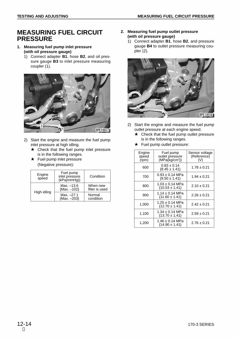
12-14 170-3 SERIES
TESTING AND ADJUSTING
MEASURING FUEL CIRCUIT PRESSURE1. Measuring fuel pump inlet pressure
(with oil pressure gauge)1) Connect adapter B1, hose B2, and oil pres-
sure gauge B3 to inlet pressure measuringcoupler (1).
2) Start the engine and measure the fuel pumpinlet pressure at high idling. Check that the fuel pump inlet pressure
is in the following ranges. Fuel pump inlet pressure
(Negative pressure):
Engine speed
Fuel pump inlet pressure(kPammHg)
Condition
High idling
Max. –13.6 Max. –102
When new filter is used
Max. –27.1Max. –203
Normal condition
2. Measuring fuel pump outlet pressure (with oil pressure gauge)1) Connect adapter B1, hose B2, and pressure
gauge B4 to outlet pressure measuring cou-pler (2).
2) Start the engine and measure the fuel pumpoutlet pressure at each engine speed. Check that the fuel pump outlet pressure
is in the following ranges. Fuel pump outlet pressure:
Enginespeed(rpm)
Fuel pump outlet pressure(MPakg/cm2)
Sensor voltage (Reference)
(V)
600 0.83 ± 0.14 8.45 ± 1.41 1.78 ± 0.21
700 0.93 ± 0.14 MPa9.50 ± 1.41 1.94 ± 0.21
800 1.03 ± 0.14 MPa10.53 ± 1.41 2.10 ± 0.21
900 1.14 ± 0.14 MPa11.60 ± 1.41 2.26 ± 0.21
1,000 1.25 ± 0.14 MPa12.70 ± 1.41 2.42 ± 0.21
1,100 1.34 ± 0.14 MPa13.70 ± 1.41 2.59 ± 0.21
1,200 1.46 ± 0.14 MPa14.90 ± 1.41 2.76 ± 0.21
➄
MEASURING FUEL CIRCUIT PRESSURE

170-3 SERIES 12-15
TESTING AND ADJUSTING
3. Measuring fuel pump outlet pressure (with sensor)1) Insert cable N7 in the connector of fuel pump
pressure sensor (3).
2) Start the engine and measure the powersource voltage of the fuel pump pressuresensor. Check that the power source voltage is
within the following range. Sensor power source voltage (between
(A) and (B)): 4.75 – 5.25 V
3) Run the engine at each speed and measurethe signal voltage of the fuel pump pressuresensor. Check that the power source voltage is
within the following range. Sensor power source voltage (between
(C) and (B)):
Engine speed(rpm)
Signalvoltage
(V)
Fuel pump outlet port pressure (reference)
(MPakg/cm2)
600 1.78±0.21 0.83±0.148.45±1.41
700 1.94±0.21 0.93±0.19.50±1.41
800 2.10±0.21 1.03±0.1410.53±1.41
900 2.26±0.21 1.14±0.1411.60±1.41
1,000 2.42±0.21 1.25±0.1412.70±1.41
1,100 2.59±0.21 1.34±0.1413.70±1.41
1,200 2.76±0.21 1.46±0.1414.90±1.41
VISUAL INSPECTION OF RETURN FUEL The fuel used for control of the timing rail in the
fuel circuit and the excessive fuel that is not usedinjected in the fuel rail are returned from theinjector through the fuel cooler to the fuel tank.
If the engine does not revolve normally or fuelconsumption is abnormally high, inspect thereturn fuel according to the following procedure.
1. Disconnect the fuel return hose before the fueltank. Plug the hole of the fuel tank. Keep the return hose open and receive the
fuel with an oil pan, etc.
2. Start the engine and check that the fuel flows outof the fuel return hose smoothly. Fuel spillage (Reference)
At low idling: 4 – 6 /min At high idling: 10 – 12 /min
If the fuel spillage is extremely low, check thereturn piping and fuel cooler for clogging.
➄
MEASURING FUEL CIRCUIT PRESSURE,VISUAL INSPECTION OF RETURN FUEL
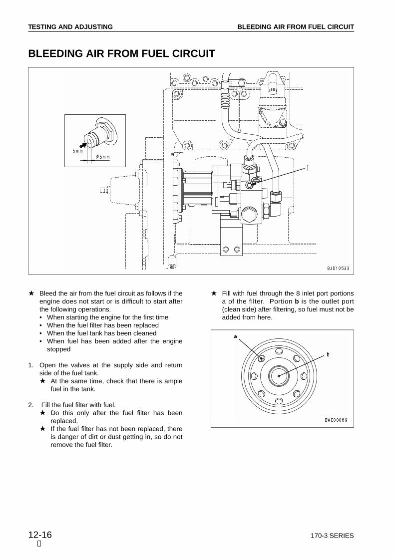
12-16 170-3 SERIES
TESTING AND ADJUSTING
Bleed the air from the fuel circuit as follows if theengine does not start or is difficult to start afterthe following operations.• When starting the engine for the first time• When the fuel filter has been replaced• When the fuel tank has been cleaned• When fuel has been added after the engine
stopped
1. Open the valves at the supply side and returnside of the fuel tank. At the same time, check that there is ample
fuel in the tank.
2. Fill the fuel filter with fuel. Do this only after the fuel filter has been
replaced. If the fuel filter has not been replaced, there
is danger of dirt or dust getting in, so do notremove the fuel filter.
Fill with fuel through the 8 inlet port portionsa of the filter. Portion b is the outlet port(clean side) after filtering, so fuel must not beadded from here.
➃
BLEEDING AIR FROM FUEL CIRCUIT
BLEEDING AIR FROM FUEL CIRCUIT


170-3 SERIES 12-21
TESTING AND ADJUSTING
PRECAUTIONS WHEN OPERATING ENGINE AS AN INDIVIDUAL PART When operating the engine as an individual part
on a bench, the lubricating conditions are differ-ent from the condition when the engine ismounted on the machine, so be careful to usethe correct rear oil seal.
1. When operating as an individual part on abenchWhen operating the engine as an individual part,use the single-lip type oil seal shown in the dia-gram below as a test consumable part. Seal Part No. 6162-25-4251 When using a double-lip type, the lubricating
conditions are different, so there is danger ofdamaging the seal lip.
2. When installing engine on machine aftercompleting operation as an individual partWhen installing the engine to the machine,replace the oil seal with the double-lip typeshown in the diagram below. Seal Part No.: 6240-21-4250 Install the engine, taking care not to damage
it. For details, see DISASSEMBLY AND ASSEM-
BLY.
➅
PRECAUTIONS WHEN OPERATING ENGINE AS AN INDIVIDUAL PART

12-22 170-3 SERIES
TESTING AND ADJUSTING
➅
ARRANGEMENT OF CONTROL DEVICES AND ELECTRIC CIRCUIT DIAGRAM FOR HPIArrangement of control devices (for troubleshooting)
ARRANGEMENT OF CONTROL DEVICES ANDELECTRIC CIRCUIT DIAGRAM FOR HPI
170-3 SERIES 12-23
TESTING AND ADJUSTING
Controller pump valve 1. Engine controller
a The engine controller of the generator specificationis installed on the machine side and that of the con-struction machine specification is installed on theengine side.
2. Fuel pump assembly 3. Control valve assembly
Sensors 4. Atmospheric pressure sensor (AAPR) 5. Boost pressure sensor (IMPR) 6. Intake air temperature sensor (IMTS) 7. Oil pressure sensor (OPS) 8. Fuel temperature sensor (FLTP) 9. Water temperature sensor (CLTP)10. Speed sensor (SP)11. Fuel pump pressure sensor (PMPR)12. Fuel rail pressure sensor (RPR)13. Timing rail pressure sensor (TPR)
Actuator14. Fuel pump actuator (FLTP)15. Fuel shut-off valve (FSO+, FSO)16. Fuel rail actuator (RAIL)17. Timing rail actuator (TIMG)
(11)
ARRANGEMENT OF CONTROL DEVICES ANDELECTRIC CIRCUIT DIAGRAM FOR HPI

12-24 170-3 SERIES
TESTING AND ADJUSTING
➅
Electric circuit diagram (For troubles shooting)
ARRANGEMENT OF CONTROL DEVICES ANDELECTRIC CIRCUIT DIAGRAM FOR HPI

170-3 SERIES 12-25
TESTING AND ADJUSTING
RUN-IN STANDARD
Engine Machine model Item
Item1 2 3 4 5 6
SA6D170E-3 D375A-5
Operating time
Engine speed
Dynamometer load
Output
min
rpm
Nkg
kWHP
3
750
00
00
6
1,000
31032
2432
3
1,200
69070
6283
3
1,200
1,470150
132177
10
1,500
2,190223
246330
5
1,800
2,890295
391525
SAA6D170E-3
WA600-3
Operating time
Engine speed
Dynamometer load
Output
min
rpm
Nkg
kWHP
3
700
00
00
6
1,000
29530
2230
3
1,200
59060
5371
3
1,200
1,180120
106142
10
1,500
1,765180
199266
5
2,000
2,355240
353473
WA700-3
Operating time
Engine speed
Dynamometer load
Output
min
rpm
Nkg
kWHP
2
725
00
00
4
1,260
79581
7510
9
1,580
1,599163
190254
12
1,820
2,394244
327438
3
2,000
3,188325
478641
WD600-3
Operating time
Engine speed
Dynamometer load
Output
min
rpm
Nkg
kWHP
3
700
00
00
6
1,000
30531
2331
3
1,200
62063
5574
3
1,200
1,275130
115154
10
1,500
1,885192
212284
5
2,000
2,470252
370497
PC1250-7
Operating time
Engine speed
Dynamometer load
Output
min
rpm
Nkg
kWHP
2
900
00
00
8
1,000
68069
5168
2
1,200
1,750178
164211
3
1,500
2,810287
316424
5
1,800
3,600367
485651
HD465-7
HD605-7
Operating time
Engine speed
Dynamometer load
Output
min
rpm
Nkg
kWHP
2
750
00
00
8
1,000
71072
5371
2
1,200
1,800184
163218
3
1,500
2,870293
324434
5
2,000
3,560363
533715
Generator
Operating time
Engine speed
Dynamometer load
Output
min
rpm
Nkg
kWHP
3
800
00
00
6
1,000
54055
4054
3
1,200
1,080110
97130
3
1,200
2,160220
194260
10
1,500
3,240330
364488
5
1,800
4,310440
583781
SAA6D170E2-3DCA-800SSK2 (DENYO GENERATOR)
Operating time
Engine speed
Dynamometer load
Output
min
rpm
Nkg
kWHP
3
800
00
00
6
1,000
698713
94126
3
1,200
1,396142
189253
3
1,200
2,791285
377505
10
1,500
4,187427
566758
5
1,800
5,570568
7521,009
RUN-IN STANDARD
(10)

12-26 170-3 SERIES
TESTING AND ADJUSTING
PERFORMANCE TEST STANDARDS
a This table shows the standard values using the JIS correction factor. a The output and torque values in the table are the standard values with the fan removed, so they are different
from the specification values. a The table shows the standard values with an air cleaner installed, muffler installed, alternator under no load,
and air compressor open (when installed). a The dynamometer load shows the value for an arm length of 716 mm.
Engine Machine model Test item Specification
value (net)Speed(rpm)
Dynamometer load
(Nkg)
SA6D170E-3 D375A-5
Rated horsepower
Max. torque
High idling speed
Low idling speed
391kW524HP/1,800 rpm
2,650Nm270kg/1,300 rpm
2,100 ± 40 rpm
750 rpm
1,800 ± 5
1,300 ± 100
2,100 ± 40
750
SAA6D170E-3
WA600-3
Rated horsepower
Max. torque (net)
High idling speed
Low idling speed
337kW452HP/2,000 rpm
2,120Nm216kg/1,400 rpm
2,170 ± 30 rpm
700 ± 25 rpm
2,000 ± 5
1,400 ± 100
2,170 ± 30
700 ± 25 rpm
WA700-3
Rated horsepower
Max. torque (net)
High idling speed
Low idling speed
478kW641HP/2,000 rpm
2,806Nm286kg/1,400 rpm
2,240 ± 30 rpm
725 ± 25 rpm
2,000 ± 5
1,400 ± 100
2,240 ± 30
725 ± 25 rpm
WD600-3
Rated horsepower
Max. torque (net)
High idling speed
Low idling speed
370kW/2,000 rpm 497HP/2,000 rpm2,391Nm/1,400 rpm 244 kgm/1,400 rpm
2,190 ± 30 rpm
700 ± 25 rpm
2,000 ± 5
1,400 ± 100
2,190 ± 30
700 ± 25 rpm
PC1250-7
Rated horsepower
Max. torque (net)
High idling speed
Low idling speed
485kW651HP/1,800 rpm
2,913Nm297kg/1,300 rpm
2,000 ± 40 rpm
900 ± 25 rpm
1,800 ± 5
1,300 ± 5
2,000 ± 40 rpm
900 ± 25 rpm
HD465-7
HD605-7
Rated horsepower
Max. torque (net)
High idling speed
Low idling speed
533kW715HP/2,000 rpm
3,207Nm327kg/1,400 rpm
2,270 ± 50 rpm
750 ± 50 rpm
2,000 ± 5
1,400 ± 5
2,270 ± 50 rpm
750 ± 50 rpm
Generator (50HZ specifi-cation)
Rated horsepower
Max. torque (net)
High idling speed
Low idling speed
570kW/1,500 rpm764 HP/1,500 rpm
Max. 1570 rpm
800 ± 50 rpm
1,500 ± 5
Max. 1570 rpm
800 ± 50 rpm
4,920 5,220502 532
+500
+500
(9)
PERFORMANCE TEST STANDARDS

170-3 SERIES 12-27
TESTING AND ADJUSTING
a Use JIS No. 2 diesel oil as the fuel. a Use SAE15W-40 or SAE30 as the lubricating oil.
Output (gross)(kWHP)
Torque (gross)(Nmkgm)
Fuelconsumption(sec/500cc)
Cooling water temperature
(°C)
Lubricating oil temperature
(°C)
Lubricating oil pressure
(kPakg/cm2)
Exhausttemperature
(°C)
70 90
70 90
70 90
70 90
90 110
90 110
90 110
80 110
343 5393.5 5.5343 5393.5 5.5343 5393.5 5.5Min. 118Min. 1.2
Max. 650
Max. 650
70 90
70 90
70 90
70 90
90 110
90 110
90 110
80 110
343 5393.5 5.5343 5393.5 5.5343 5393.5 5.5Min. 118Min. 1.2
Max. 650
Max. 650
70 90
70 90
70 90
70 90
90 110
90 110
90 110
80 110
343 5393.5 5.5343 5393.5 5.5343 5393.5 5.5Min. 118Min. 1.2
Max. 650
Max. 650
70 90
70 90
70 90
70 90
90 110
90 110
90 110
80 110
343 5393.5 5.5343 5393.5 5.5343 5393.5 5.5Min. 118Min. 1.2
Max. 650
Max. 650
70 90
70 90
70 90
70 90
90 110
90 110
90 110
80 110
343 5393.5 5.5343 5393.5 5.5343 5393.5 5.5Min. 118Min. 1.2
Max. 650
Max. 650
70 90
70 90
70 90
70 90
90 110
90 110
90 110
80 110
343 5393.5 5.5343 5393.5 5.5343 5393.5 5.5Min. 118Min. 1.2
Max. 650
Max. 650
552 585741 787
70 90
70 90
70 90
70 90
90 110
90 110
90 110
80 110
343 5393.5 5.5343 5393.5 5.5343 5393.5 5.5Min. 118Min. 1.2
Max. 650
Max. 650
(9)
PERFORMANCE TEST STANDARDS
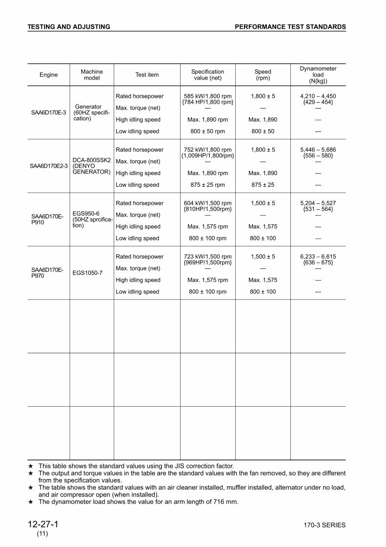
12-27-1 170-3 SERIES
TESTING AND ADJUSTING
a This table shows the standard values using the JIS correction factor. a The output and torque values in the table are the standard values with the fan removed, so they are different
from the specification values. a The table shows the standard values with an air cleaner installed, muffler installed, alternator under no load,
and air compressor open (when installed). a The dynamometer load shows the value for an arm length of 716 mm.
Engine Machine model Test item Specification
value (net)Speed(rpm)
Dynamometer load
(Nkg)
SAA6D170E-3 Generator (60HZ specifi-cation)
Rated horsepower
Max. torque (net)
High idling speed
Low idling speed
585 kW/1,800 rpm784 HP/1,800 rpm
Max. 1,890 rpm
800 ± 50 rpm
1,800 ± 5
Max. 1,890
800 ± 50
4,210 4,450429 454
SAA6D170E2-3DCA-800SSK2 (DENYO GENERATOR)
Rated horsepower
Max. torque (net)
High idling speed
Low idling speed
752 kW/1,800 rpm1,009HP/1,800rpm
Max. 1,890 rpm
875 ± 25 rpm
1,800 ± 5
Max. 1,890
875 ± 25
5,446 5,686556 580
SAA6D170E-P910
EGS950-6 (50HZ sprcifica-tion)
Rated horsepower
Max. torque (net)
High idling speed
Low idling speed
604 kW/1,500 rpm810HP/1,500rpm
Max. 1,575 rpm
800 ± 100 rpm
1,500 ± 5
Max. 1,575
800 ± 100
5,204 5,527531 564
SAA6D170E-P970 EGS1050-7
Rated horsepower
Max. torque (net)
High idling speed
Low idling speed
723 kW/1,500 rpm969HP/1,500rpm
Max. 1,575 rpm
800 ± 100 rpm
1,500 ± 5
Max. 1,575
800 ± 100
6,233 6,615636 675
(11)
PERFORMANCE TEST STANDARDS

170-3 SERIES 12-27-2
TESTING AND ADJUSTING
a Use JIS No. 2 diesel oil as the fuel. a Use SAE15W-40 or SAE30 as the lubricating oil.
Output (gross)(kWHP)
Torque (gross)(Nmkgm)
Fuelconsumption(sec/500cc)
Cooling water temperature
(°C)
Lubricating oil temperature
(°C)
Lubricating oil pressure
(kPakg/cm2)
Exhausttemperature
(°C)
566 600761 807
70 90
70 90
70 90
70 90
90 110
90 110
90 110
80 110
343 5393.5 5.5343 5393.5 5.5343 5393.5 5.5Min. 118Min. 1.2
Max. 650
Max. 650
733 771986 1,037
70 90
70 90
70 90
70 90
90 110
90 110
90 110
80 110
343 5393.5 5.5343 5393.5 5.5343 5393.5 5.5Min. 118Min. 1.2
Max. 650
Max. 650
607 645813 865
70 90
70 90
70 90
90 110
90 110
90 110
343 5393.5 5.5
Min. 118
Min. 1.2
Max. 680
723 767969 1,030
70 90
70 90
70 90
90 110
90 110
90 110
343 5393.5 5.5
Min. 118
Min. 1.2
Max. 690
PERFORMANCE TEST STANDARDS
(11)


170-3 SERIES 12-101
TROUBLESHOOTING OF MECHANICAL SYSTEM(S MODE)
Points to remember when troubleshooting.................................................................................................. 12-102Method of using troubleshooting chart ........................................................................................................ 10-103S- 1 Starting performance is poor (starting always takes time) .............................................................. 12-106S- 2 Engine does not start ..................................................................................................................... 12-107
a) Engine does not turn ................................................................................................................. 12-107b) Engine turns but no exhaust smoke comes out (fuel is not being injected) .............................. 12-108c) Exhaust smoke comes out but engine does not start (fuel is being injected) ........................ 12-108-2
S- 3 Engine does not pick up smoothly (follow-up is poor) .....................................................................12-110S- 4 Engine stops during operations ................................................................................................... 12-110-2S- 5 Engine does not rotate smoothly (hunting) ......................................................................................12-112S- 6 Engine lacks output (or lacks power)........................................................................................... 12-112-2S- 7 Exhaust smoke is black (incomplete combustion) ..........................................................................12-114S- 8 Oil consumption is excessive (or exhaust smoke is blue) ..............................................................12-115S- 9 Oil becomes contaminated quickly .................................................................................................12-116S-10 Fuel consumption is excessive ........................................................................................................12-117S-11 Oil is in cooling water, or water spurts back, or water level goes down ..........................................12-118S-12 Oil pressure caution lamp lights up (drop in oil pressure)................................................................12-119S-13 Oil level rises .................................................................................................................................. 12-120S-14 Water temperature becomes too high (overheating) ..................................................................... 12-121S-15 Abnormal noise is made ................................................................................................................. 12-122S-16 Vibration is excessive ..................................................................................................................... 12-123
➅

12-102 170-3 SERIES
TROUBLESHOOTING POINTS TO REMEMBER WHEN TROUBLESHOOTING
➀
POINTS TO REMEMBER WHEN TROUBLESHOOTING
Stop the machine in a level place, and check that the safety pins and blocks are securely fitted, and theparking brake is securely applied.
When carrying out the operation with two or more workers, keep strictly to the agreed signals, and do notallow any unauthorized person to come near.
If the radiator cap is removed when the engine is still hot, boiling water may spurt out and cause seriousburns. Always wait for the water temperature to go down before removing the radiator cap.
Be extremely careful not to touch any hot parts or to get caught in any rotating parts.
When disconnecting wiring, always disconnect the negative (–) terminal of the battery first.
When removing a plug or cap from a location which is under pressure from oil, water, or air, always releasethe internal pressure first. When installing measuring equipment, be sure to connect it properly.
The aim of troubleshooting is to pinpoint the basic cause of the failure, to carry out repairs swiftly, and to preventreoccurrence of the failure. When carrying out troubleshooting, and important point is of course to understandthe structure and function. However, a short cut to effective troubleshooting is to ask the operator variousquestions to form some idea of possible causes of the failure that would produce the reported symptoms.
1. When carrying out troubleshooting, do nothurry to disassemble the components If components are disassembled immediatelyany failure occurs:• Parts that have no connection with the failure
or other unnecessary parts will be disassem-bled
• It will become impossible to find the cause ofthe failure.
It will also cause a waste of man-hours, parts, oroil or grease, and at the same time, will also losethe confidence of the user or operator. For this reason, when carrying out troubleshoot-ing, it is necessary to carry out thorough priorinvestigation and to carry out troubleshooting inaccordance with the fixed procedure.
2. Points to ask user or operator1) Have any other problems occurred apart
from the problem that has been reported? 2) Was there anything strange about the
machine before the failure occurred? 3) Did the failure occur suddenly, or were there
problems with the machine condition beforethis?
4) Under what conditions did the failure occur? 5) Had any repairs been carried out before the
failure? When were these repairs carriedout?
6) Has the same kind of failure occurredbefore?
3. Checks before troubleshooting1) Is there any sign of abnormality in the
machine or engine?2) Always carry out the Checks before starting.3) Carry out other checks if necessary.4) Other maintenance items can be checked
externally, so check any item that is consid-ered to be necessary.
5) Check for any error display on the controller.
4. Confirming failureConfirm the extent of the failure yourself, andjudge whether to handle it as a real failure or asa problem with the method of operation, etc. When operating the machine to re-enact the
troubleshooting symptoms, do not carry outany investigation or measurement that maymake the problem worse.
5. TroubleshootingUse the results of the investigation and inspec-tion in Items 2 – 4 to narrow down the causes offailure, then use the troubleshooting matrix orflowchart to locate the position of the failureexactly. The basic procedure for troubleshooting is
as follows.1) Start from the simple points. 2) Start from the most likely points. 3) Investigate other related parts or informa-
tion.
6. Measures to remove root cause of failureEven if the failure is repaired, if the root cause ofthe failure is not repaired, the same failure willoccur again. To prevent this, always investigate why theproblem occurred. Then, remove the rootcause.

170-3 SERIES 12-103
TROUBLESHOOTING METHOD OF USING TROUBLESHOOTING CHARTS
➀
METHOD OF USING TROUBLESHOOTING CHARTSThis troubleshooting chart is divided into three sec-tions: questions, check items, and troubleshoot-ing. The questions and check items are used topinpoint high probability causes that can be locatedfrom the failure symptoms or simple inspeciton with-out using troubleshooting tools.Next, troubleshooting tools or direct inspection areused to check the high probability causes to makefinal confirmation.
[Questions]Sections + in the chart on the right corre-sponds to the items where answers can beobtained from the user. The items in areitems that can be obtained from the user,depending on the user's level.
[Check items]The serviceman carries out simple inspection tonarrow down the causes. The items under inthe chart on the right correspond to this.The serviceman narrows down the causes frominformation that he has obtained from theuser and the results of that he has obtainedfrom his own inspection.
[Troubleshooting]Troubleshooting is carried out in the order ofprobability, starting with the causes that havebeen marked as having the highest probabilityfrom information gained from [Questions] and[Check items].
The basic method of using the troubleshooting chartis as follows.Items listed for [Questions] and [Check items] thathave a relationship with the Cause items aremarked with , and of these, causes that have ahigh probability are marked with .Check each of the [Questions] and [Check items]in turn, and marked the or in the chart foritems where the problem appeared. The vertical col-umn (Causes) that has the highest number of pointsis the most probable cause, so start troubleshootingfor that item to make final confirmation of the cause.As a rule, do not use it when calculating the pointsfor locating the cause, but it can be included if nec-essary to determine the order for troubleshooting.Use the in the Cause column as reference for[Degree of use (Operated for long period)] in the[Questions] section as reference.

12-104 170-3 SERIES
TROUBLESHOOTING METHOD OF USING TROUBLESHOOTING CHART
➅
• Example of troubleshooting when exhaust gas is blackLet us assume that [Clogged air cleaner] is taken to be the cause of black exhaust gas. Three symptomshave causal relationship with this problem: [Exhaust gas slowly became black], [Power slowly becameweaker], and [Dust indicator is red].If we look from these three symptoms to find the causes, we find that there is a relationship with five causes.Let us explain here the method of using this causal relationship to pinpoint the most probable cause.
S-7 Exhaust smoke is black (incomplete combustion) General causes why exhaust smoke is black • Insufficient intake of air • Defective condition of fuel injection • Excessive injection of fuel
: Possible causes (judging from Questions and Check items)
: Most probable causes (judging from Questions and Check items)
: Possible causes due to length of use (used for a long period)
: Items to confirm the cause.
Legend
Questions
Cle
an
Repla
ce
Repla
ce
Adju
st
Corr
ect
Repla
ce
Repla
ce
Repla
ce
Repla
ce
Repla
ce
Repla
ce
Repla
ce
Check ite
ms
Tro
uble
shooting
Remedy
Clo
gged a
ir c
leaner
ele
ment
Seiz
ed turb
ocharg
er,
inte
rfere
nce
Defe
ctive c
onta
ct
of
valv
e a
nd v
alv
e s
eat
Impro
per
adju
stm
ent
of
valv
e c
leara
nce
Leakage o
f air b
etw
een turb
ocharg
er
and c
ylin
der
head
Cru
shed, clo
gged m
uffle
r
Worn
pis
ton r
ing, cylin
der
liner
Defe
ctive fuel pum
p
Defe
ctive inje
cto
r
Cut, w
orn
inje
cto
r O
-rin
g
Failu
re tim
ing r
ail
pre
ssure
sensor
Defe
ctive tim
ing r
ail
actu
ato
r (M
ark
ed )
Causes
Inspect air cleaner directly
When turbocharger is rotated by hand, it is found to be heavy
When compression pressure is measured, it is found to be low
Inspect valve clearance directly
When muffler is removed, exhaust sound improves
Inspect between turbocharger and cylinder head directly
When pressure at outlet port of fuel pump is measured, it is found to be low
When temperature of injector of each cylinder is measured, there are some cylinders that are low
Abnormality in timing rail pressure sensor system is indicated ( 1)
Inspect sensor directly (Output voltage)
Inspect actuator directly (Resistance and filter for clogging)
Confirm recent repair history
Degree of use of machine Operated for long period
Color of exhaust gas
Suddenly became black
Gradually became black
Blue under light load
Non-specified fuel is being used
Engine oil must be added more frequently
Power was lost Suddenly
Gradually
Dust indicator is red
Muffler is crushed
Leakage of air between turbocharger and head, loose clamp
When exhaust manifold is touched immediately after starting engine, temperature of some cylinders is low
Noise of interference is heard from around turbocharger
Clanging sound is heard from around cylinder head
Exhaust noise is abnormal
Engine pickup is poor and combustion is irregular
Blow-by gas is excessive

170-3 SERIES 12-105
TROUBLESHOOTING
Five causes
Step 1
Clarify the relationship between the three symptoms in
the [Questions] and [Check items] section and the five
Cause items in the vertical column.
Step 2
Add up the total of and marks where the horizontal limes for the three symptoms and the vertical columns for the causes intersect.
(1) Clogged air cleaner element:
(2) Defective contact of valve, valve seat:
(3) Leakage of air between turbocharger
and head:
(4) Worn piston ring, cylinder liner:
(5) Defective timing rail pressure sensor:
Step 3
The calculation in Step 2 show that the closest
relationship is with [Worn piston ring, cylinder liner].
Follow this column down to the troubleshooting area and
carry out the troubleshooting item marked .
The Remedy is given as [Clean], so carry out cleaning,
and the exhaust gas color should return to normal.
Three symptoms
METHOD OF USING TROUBLESHOOTING CHART
➅

12-106 170-3 SERIES
TROUBLESHOOTING
Confirm recent repair history
Degree of use of machine Operated for long period
Starting performance became worse gradually
Engine starts easily when warm
Non-specified fuel is being used
Replacement of filters has not been carried out according to Operation Manual
Engine oil must be added more frequently
Charge caution lamp lights up
When preheating, preheating indicator lamp does not light up
Dust indicator is red
Air breather hole in fuel tank cap is clogged
Starting motor cranks engine slowly
Little fuel comes out even when injection pump sleeve nut is loosened
Little fuel comes out even when fuel filter air bleed plug is loosened
When exhaust manifold is touched immediately after starting engine, temperature
of some cylinders is low
Engine does not pick up smoothly, and combustion is irregular
There is hunting from engine (rotation is irregular)
Blow-by gas is excessive
Difficult to stop engine
Qu
estio
ns
Ch
eck ite
ms
When engine is cranked with starting motor,
Inspect air cleaner element directly
When compression pressure is measured, it is found to be low
Inspect fuel filter, strainer directly
When negative pressure at inlet port of fuel pump is measured, it is found to be high
When pressure at outlet port of fuel pump is measured, it is found to vary
When pressure at outlet port of fuel pump is measured, it is found to be low
Inspect fuel pump directly
Inspect fuel shut-off valve directly
Inspect timing rail actuator screen directly
When temperature of exhaust gas of each cylinder is measured, there are some
cylinders that are low
Inspect injector directly
When specific gravity of electrolyte and voltage of battery are measured, one of
them is low
When starting switch is turned to HEAT, heater mount does not become warm
Is voltage 26 - 30V between alternator terminal B and terminal E with
engine at low idling?
Inspect sensor directly (Output voltage and resistance)
Inspect actuator directly (Resistance and filter for clogging)
Tro
ub
lesh
oo
tin
g
Yes
No
Cle
an
Co
rre
ct
Re
pla
ce
Co
rre
ct
Cle
an
Cle
an
Re
pla
ce
Re
pla
ce
Cle
an
Re
pla
ce
Re
pla
ce
Re
pla
ce
Re
pla
ce
Re
pla
ce
Re
pla
ce
Re
pla
ce
Remedy
Clo
gg
ed
air c
lea
ne
r e
lem
en
t
De
fective
co
nta
ct
of
va
lve
, va
lve
se
at
Wo
rn p
isto
n r
ing
, cylin
de
r lin
er
Clo
gg
ed
fu
el ta
nk c
ap
Clo
gg
ed
fu
el filte
r, s
tra
ine
r
Lo
ose
pip
ing
, fu
el filte
r, e
ntr
y o
f a
ir
De
fective
fu
el p
um
p
De
fective
sh
ut-
off v
alv
e
Clo
gg
ed
tim
ing
ra
il a
ctu
ato
r scre
en
De
fective
in
jecto
r
De
fective
in
jecto
r ch
eck b
all
Cu
t, w
orn
in
jecto
r O
-rin
g
De
fective
or
de
terio
rate
d b
att
ery
Defe
ctive p
reheating c
ircuit (
when s
tart
ing in low
tem
pera
ture
s)
De
fective
alte
rna
tor
De
fective
alte
rna
tor
reg
ula
tor
Causes
S-1 Starting performance is poor (starting always takes time)
General causes why starting performance is poor • Defective electrical system • Insufficient supply of fuel • Insufficient intake of air • Improper selection of fuel • Defective HPI sensor • Defective HPI actuator
S-1
➅

170-3 SERIES 12-106-1
TROUBLESHOOTING
Re
pla
ce
Re
pla
ce
Re
pla
ce
Re
pla
ce
Re
pla
ce
Re
pla
ce
Re
pla
ce
Re
pla
ce
Re
pla
ce
Re
pla
ce
De
fective
atm
osp
he
ric p
ressu
re s
en
so
r
De
fective
bo
ost
pre
ssu
re s
en
so
r
De
fective
fu
el ra
il p
ressu
re s
en
so
r
De
fective
tim
ing
ra
il p
ressu
re s
en
so
r
De
fective
fu
el p
um
p p
ressu
re s
en
so
r
De
fective
wa
ter
tem
pe
ratu
re s
en
so
r
De
fective
in
take
ma
nifo
ld t
em
pe
ratu
re s
en
so
r
De
fective
fu
el ra
il a
ctu
ato
r (M
ark
ed
1)
De
fective
tim
ing
ra
il a
ctu
ato
r (M
ark
ed
1
)
De
fective
fu
el p
um
p a
ctu
ato
r (M
ark
ed
1
)
Causes
➅
S-1
1.If the following error codes are displayed, carry outthe troubleshooting in "EA mode" or "EB mode". (Ifany of the following error codes is not displayed, theyare not probably the cause of the trouble. In thiscase, inspect the other devices for the cause.)[514][E-73]:Abnormality in fuel rail actuator[112] [E-83]:Abnormality in timing rail actuator[318][E-93]:Abnormality in fuel pump actuator

170-3 SERIES 12-107
TROUBLESHOOTING
Confirm recent repair history
Degree of use of machine Operated for long period
Horn does not sound
Horn volume is low
Battery electrolyte is low
Battery terminal is loose
When starting switch is turned to ON, there is no clicking sound from battery relay
When starting switch is turned to START, starting pinion does not move out
Speed of rotation is low
Makes grating noise
Soon disengages again
Makes rattling noise and does not turn
Qu
estio
ns
Ch
eck ite
ms
Condition of horn when starting
switch is turned ON
Inspect flywheel ring gear directly
When specific gravity of electrolyte and voltage of battery are measured, one of them is low
When terminal B and terminal C of starting switch are connected, engine starts
There is no 24V between battery relay terminal B and terminal E
When terminal B and terminal C of starting motor are connected, engine starts
When terminal B and terminal C of safety relay are connected, engine starts
When terminal of safety switch and terminal B of starting motor are connected, engine starts
Tro
ub
lesh
oo
tin
g
Re
pla
ce
Re
pla
ce
Co
rre
ct
—
Re
pla
ce
Re
pla
ce
Re
pla
ce
Re
pla
ce
Remedy
Bro
ke
n f
lyw
he
el rin
g g
ea
r
De
fective
or
de
terio
rate
d b
att
ery
De
fective
ba
tte
ry t
erm
ina
l co
nn
ectio
n
De
fective
sta
rtin
g c
ircu
it w
irin
g
De
fective
sta
rtin
g s
witch
De
fective
ba
tte
ry r
ela
y
De
fective
sta
rtin
g m
oto
r
De
fective
sa
fety
re
lay o
r sa
fety
sw
itch
Causes
When starting switch is turned
to START, starting pinion moves
out, but
Turn starting switch OFF, connect cord, and carry out troubleshooting at ON
1. Carry out troubleshooting of machine
1.
S-2 Engine does not start
a) Engine does not turn
General causes why engine does not turn Internal parts of engine seized
a See Troubleshooting S-4. Defective electrical system Problem in power train (troubleshooting for machine)
a See the manual for the machine.
S-2
(10)

12-108 170-3 SERIES
TROUBLESHOOTING
Confirm recent repair history
Degree of use of machine Operated for long period
Exhaust smoke suddenly stopped coming out (when starting again)
Starting performance became worse gradually
Starts when engine is warm
Replacement of filters has not been carried out according to Operation Manual
When fuel tank is inspected, it is found to be empty
Air breather hole in fuel tank cap is clogged
Rust and water are found when fuel tank is drained
When fuel filter is drained, fuel does not come out
There is leakage from fuel piping
Wiring of fuel shut-off valve is loose
Cylinder block ground wiring is loose
Fuel pump outlet port coupler is pushed, almost no fuel comes out
Fuel pump outlet port coupler is pushed, air comes out together with fuel
Qu
estio
ns
Ch
eck ite
ms
When negative pressure at inlet port of fuel pump is measured, it is found to be high
Inspect fuel filter, strainer directly
Inspect fuel pump drive shaft directly
Inspect fuel shut-off valve directly
When starting switch is turned to START, voltage [24V] is not generated between fuel shut-off valve connector
pins
Inspect timing rail actuator screen directly
Inspect sensor directly (Output voltage and resistance)
Inspect actuator directly (Resistance and filter for clogging)
Tro
ub
lesh
oo
tin
g
Ad
d
Co
rre
ct
Cle
an
Cle
an
Re
pla
ce
Re
pla
ce
Re
pla
ce
Re
pla
ce
Re
pla
ce
Remedy
Insu
ffic
ien
t fu
el in
ta
nk
Clo
gg
ed
fu
el ta
nk c
ap
Lo
ose
pip
ing
, fu
el filte
r, e
ntr
y o
f a
ir
Clo
gg
ed
fu
el filte
r, s
tra
ine
r
Bro
ke
n f
ue
l p
um
p d
rive
sh
aft
De
fective
fu
el sh
ut-
off v
alv
e
De
fective
fu
el sh
ut-
off v
alv
e w
irin
g
Clo
gg
ed
tim
ing
actu
ato
r scre
en
De
fective
atm
osp
he
ric p
ressu
re s
en
so
r
Causes
When engine is cranked with
starting motor, and
b) Engine turns but no exhaust smoke comes out (fuel is not being injected)
General causes why engine turns but no exhaust smoke comes out Fuel is not being supplied Supply of fuel is extremely small Improper selection of fuel (particularly in winter) Defective HPI sensor Defective HPI actuator
S-2
(10)

170-3 SERIES 12-108-1
TROUBLESHOOTING
Re
pla
ce
Re
pla
ce
Re
pla
ce
Re
pla
ce
Re
pla
ce
Re
pla
ce
Re
pla
ce
Re
pla
ce
Re
pla
ce
Causes
De
fective
bo
ost
pre
ssu
re s
en
so
r
De
fective
fu
el ra
il p
ressu
re s
en
so
r
De
fective
tim
ing
ra
il p
ressu
re s
en
so
r
De
fective
fu
el p
um
p p
ressu
re s
en
so
r
De
fective
wa
ter
tem
pe
ratu
re s
en
so
r
De
fective
in
take
ma
nifo
ld t
em
pe
ratu
re s
en
so
r
De
fective
fu
el ra
il a
ctu
ato
r (M
ark
ed
1)
De
fective
tim
ing
ra
il a
ctu
ato
r (M
ark
ed
1
)
De
fective
fu
el p
um
p a
ctu
ato
r (M
ark
ed
1
)
(10)
S-2
1.If the following error codes are displayed, carry outthe troubleshooting in "EA mode" or "EB mode". (Ifany of the following error codes is not displayed, theyare not probably the cause of the trouble. In thiscase, inspect the other devices for the cause.)[514][E-73]:Abnormality in fuel rail actuator[112] [E-83]:Abnormality in timing rail actuator[318][E-93]:Abnormality in fuel pump actuator

12-108-2 170-3 SERIES
TROUBLESHOOTING
Confirm recent repair history
Degree of use of machine Operated for long period
Suddenly failed to start
Starting performance became worse gradually
Starts when engine is warm
Non-specified fuel is being used
Replacement of filters has not been carried out according to Operation Manual
Engine oil must be added more frequently
When preheating, preheating indicator lamp does not light up
Dust indicator is red
Air breather hole in fuel tank cap is clogged
Rust and water are found when fuel tank is drained
When fuel filter is drained, no fuel comes out
There is leakage from fuel piping
Starting motor cranks engine slowly
When engine is cranked, abnormal noise is generated around cylinder head
Fuel pump outlet port coupler is pushed, almost no fuel comes out
Fuel pump outlet port coupler is pushed, air comes out together with fuel
Qu
estio
ns
Inspect air cleaner element directly
Inspect dynamic valve system directly
When compression pressure is measured, it is found to be low
When negative pressure at inlet port of fuel pump is measured, it is found to be high
When fuel filter, strainer directly
Inspect fuel pump directly
Inspect timing rail actuator screen directly
When temperature of exhaust gas of each cylinder is measured, there are some cylinders that are low
When specific gravity of electrolyte and voltage of battery are measured, one of them is low
When starting switch is at HEAT, heater mount does not become warm
Inspect sensor directly (Output voltage and resistance)
Inspect actuator directly (Resistance and filter for clogging)
Inspect fuel rail actuator directly
Tro
ub
lesh
oo
tin
g
Cle
an
Repla
ce
Repla
ce
Cle
an
Cle
an
Cle
an
Repla
ce
Repla
ce
Repla
ce
Repla
ce
Corr
ect
Remedy
Clo
gg
ed
air c
lea
ne
r e
lem
en
t
De
fective
dyn
am
ic v
alv
e s
yste
m (
va
lve
, ro
cke
r a
rm,
etc
.)
Wo
rn p
isto
n r
ing
, cylin
de
r lin
er
Clo
gg
ed
fu
el ta
nk c
ap
Lo
ose
pip
ing
, fu
el filte
r, e
ntr
y o
f a
ir
Clo
gg
ed
fu
el filte
r, s
tra
ine
r
De
fective
fu
el p
um
p
Clo
gg
ed
tim
ing
actu
ato
r scre
en
De
fective
in
jecto
r
De
fective
or
de
terio
rate
d b
att
ery
De
fective
pre
he
atin
g h
ea
ter
circu
it
When engine is cranked with starting motor, and
Ch
eck ite
ms
Causes
c) Exhaust smoke comes out but engine does not start (fuel is being injected)
General causes why exhaust smoke comes out but engine does not start Lack of rotating force due to defective electrical system Insufficient supply of fuel Insufficient intake of air Improper selection of fuel and oil Defective HPI sensor Defective HPI actuator
(10)
S-2

170-3 SERIES 12-109
TROUBLESHOOTING
Repla
ce
Repla
ce
Repla
ce
Repla
ce
Repla
ce
Repla
ce
Repla
ce
Repla
ce
Repla
ce
Repla
ce
Repla
ce
Causes
De
fective
atm
osp
he
ric p
ressu
re s
en
so
r
De
fective
bo
ost
pre
ssu
re s
en
so
r
De
fective
fu
el ra
il p
ressu
re s
en
so
r
De
fective
tim
ing
ra
il p
ressu
re s
en
so
r
De
fective
fu
el p
um
p p
ressu
re s
en
so
r
De
fective
wa
ter
tem
pe
ratu
re s
en
so
r
De
fective
in
take
ma
nifo
ld t
em
pe
ratu
re s
en
so
r
De
fective
fu
el ra
il a
ctu
ato
r (M
ark
ed
1)
De
fective
tim
ing
ra
il a
ctu
ato
r (M
ark
ed
1
)
De
fective
fu
el p
um
p a
ctu
ato
r (M
ark
ed
1)
Clo
gg
ed
fu
el ra
il a
ctu
ato
r
S-2
(10)
1.If the following error codes are displayed, carry outthe troubleshooting in "EA mode" or "EB mode". (Ifany of the following error codes is not displayed, theyare not probably the cause of the trouble. In thiscase, inspect the other devices for the cause.)[514][E-73]:Abnormality in fuel rail actuator[112] [E-83]:Abnormality in timing rail actuator[318][E-93]:Abnormality in fuel pump actuator

12-110 170-3 SERIES
TROUBLESHOOTING
Confirm recent repair history
Degree of use of machine Operated for long period
Engine pick-up suddenly became worse
Non-specified fuel is being used
Replacement of filters has not been carried out according to Operation Manual
Engine oil must be added more frequently
Dust indicator is red
Air breather hole in fuel tank cap is clogged
Rust and water are found when fuel is drained
There is leakage from fuel piping
Fuel pump outlet port coupler is pushed, almost no fuel comes out
Fuel pump outlet port coupler is pushed, air comes out together with fuel
When exhaust manifold is touched immediately after starting engine, temperature of some cylinders is low
Blue under light load
Black
Clanging sound is heard from around cylinder head
Noise of interference is heard from around turbocharger
High idling speed under no load is normal, but speed suddenly drops when load is applied
There is hunting from engine (rotation is irregular)
Blow-by gas is excessive
Qu
estio
ns
Ch
eck ite
ms
When engine is cranked
with starting motor, and
Inspect air cleaner element directly
When turbocharger is rotated by hand, it is found to be heavy
When compression pressure is measured, it is found to be low
Inspect valve clearance directly
When pressure at outlet port of fuel pump is measured, it is found to vary
Inspect fuel filter, strainer directly
When negative pressure at inlet port of fuel pump is measured, it is found to be high
When pressure at outlet port of fuel pump is measured, it is found to be low
When temperature of injector of each cylinder is measured, there are some cylinders that are low
When intake air pressure (boost pressure) is measured, it is found to be normal
Inspect actuator directly (Resistance and filter for clogging)
Inspect sensor directly (Output voltage and resistance)
Inspect for air leakage
Tro
ub
lesh
oo
tin
g
Cle
an
Co
rre
ct
Re
pla
ce
Co
rre
ct
Re
pla
ce
Co
rre
ct
Cle
an
Cle
an
Re
pla
ce
Re
pla
ce
Re
pla
ce
Remedy
Clo
gg
ed
air c
lea
ne
r e
lem
en
t
Se
ize
d t
urb
och
arg
er
De
fective
co
nta
ct
of
va
lve
an
d v
alv
e s
ea
t
Imp
rop
er
va
lve
cle
ara
nce
Wo
rn p
isto
n r
ing
, cylin
de
r lin
er
Clo
gg
ed
fu
el ta
nk c
ap
Lo
ose
pip
ing
, fu
el filte
r, e
ntr
y o
f a
ir
Clo
gg
ed
fu
el filte
r, s
tra
ine
r
De
fective
fu
el p
um
p
De
fective
in
jecto
r
Fa
ilure
bo
ost
pre
ssu
re s
en
so
r
Causes
Color of exhaust gas
S-3 Engine does not pick up smoothly (follow-up is poor)
General causes why engine does not pick up smoothly • Insufficient intake of air • Insufficient supply of fuel • Defective condition of fuel spray • Improper fuel used • Abnormality in fuel control system • Defective HPI sensor • Defective HPI actuator • Normal output is not applied
→ See Troubleshooting S-6
S-3
➅
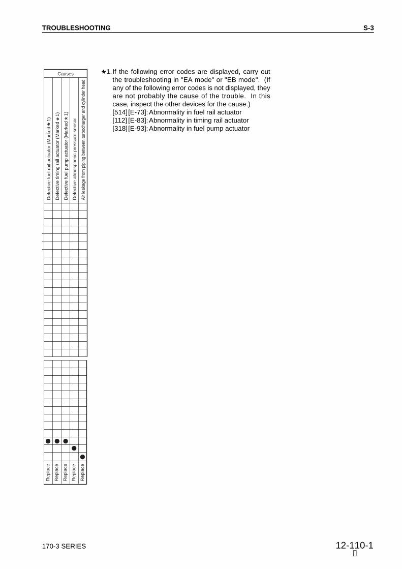
170-3 SERIES 12-110-1
TROUBLESHOOTING
Re
pla
ce
Re
pla
ce
Re
pla
ce
Re
pla
ce
Re
pla
ce
De
fective
fu
el ra
il a
ctu
ato
r (M
ark
ed
1)
De
fective
tim
ing
ra
il a
ctu
ato
r (M
ark
ed
1
)
De
fective
fu
el p
um
p a
ctu
ato
r (M
ark
ed
1
)
De
fective
atm
osp
he
ric p
ressu
re s
en
so
r
Air le
aka
ge fro
m p
ipin
g b
etw
een turb
och
arg
er
and c
ylin
der
head
Causes
➅
S-3
1.If the following error codes are displayed, carry outthe troubleshooting in "EA mode" or "EB mode". (Ifany of the following error codes is not displayed, theyare not probably the cause of the trouble. In thiscase, inspect the other devices for the cause.)[514][E-73]:Abnormality in fuel rail actuator[112] [E-83]:Abnormality in timing rail actuator[318][E-93]:Abnormality in fuel pump actuator

12-110-2 170-3 SERIES
TROUBLESHOOTING
Confirm recent repair history
Degree of use of machine Operated for long period
Condition when engine stopped
Abnormal noise was heard and engine stopped suddenly
Engine overheated and stopped
Engine stopped slowly
There was hunting and engine stopped
Non-specified fuel is being used
Replacement of filters has not been carried out according to Operation Manual
Fuel level caution lamp lights up
When fuel tank is inspected, it is found to be empty
Air breather hole in fuel tank cap is clogged
Rust and water are found when fuel tank is drained
Metal particles are found when oil is drained
Does not turn at all
Turns in opposite direction
Moves amount of gear backlash
Fuel pump shaft does not turn
Fuel pump outlet port coupler is pushed, almost no fuel comes out
Fuel pump outlet port coupler is pushed, air comes out together with fuel
Engine turns, but stops when load is applied to machine
Qu
estio
ns
Ch
eck ite
ms When it is attempted
to turn by hand using barring tool
Inspect dynamic valve system directly
Inspect piston, connecting rod directly
Inspect main bearing, connecting rod directly
Inspect gear train directly
When pressure at outlet port of fuel pump is measured, it is found to vary
Inspect fuel filter, strainer directly
When negative pressure at inlet port of fuel pump is measured, it is found to be high
When pressure at outlet port of fuel pump is measured, it is found to be low
When temperature of injector of each cylinder is measured, there are some cylinders that are low
Engine rotates when pump auxiliary equipment (pump, compressor, etc.) is removed
Inspect sensor directly (Output voltage and resistance)
Inspect actuator directly (Resistance and filter for clogging)
Tro
ub
lesh
oo
tin
g
Re
pla
ce
Re
pla
ce
Re
pla
ce
Re
pla
ce
Ad
d
Co
rre
ct
Co
rre
ct
Cle
an
Re
pla
ce
Re
pla
ce
Re
pla
ce
—
Re
pla
ce
Remedy
Bro
ke
n d
yn
am
ic v
alv
e s
yste
m
(va
lve
, ro
cke
r a
rm,
etc
.)
Bro
ke
n,
se
ize
d p
isto
n,
co
nn
ectin
g r
od
Bro
ke
n,
se
ize
d m
ain
be
arin
g,
co
nn
ectin
g r
od
be
arin
g
Bro
ke
n,
se
ize
d g
ea
r tr
ain
Insu
ffic
ien
t fu
el in
ta
nk
Clo
gg
ed
fu
el ta
nk c
ap
Lo
ose
pip
ing
, fu
el filte
r, e
ntr
y o
f a
ir
Clo
gg
ed
fu
el filte
r, s
tra
ine
r
Bro
ke
n f
ue
l p
um
p d
rive
sh
aft
De
fective
in
jecto
r
Bro
ke
n a
uxili
ary
eq
uip
me
nt
(pu
mp
, co
mp
resso
r, e
tc.)
Fa
ilure
in
po
we
r tr
ain
(tr
ou
ble
sh
oo
tin
g f
or
ma
ch
ine
)
De
fective
atm
osp
he
ric p
ressu
re s
en
so
r
Causes
When engine is cranked with starting motor, and
Ca
rry o
ut
tro
ub
lesh
oo
tin
g o
f m
ach
ine
S-4 Engine stops during operations
General causes why engine stops during operations • Seized parts inside engine • There is overheating
See Troubleshooting S-14. • Problem in power train (troubleshooting for machine)
See the manual for the machine. • Defective HPI sensor • Defective HPI actuator
➅
S-4

170-3 SERIES 12-111
TROUBLESHOOTING
Re
pla
ce
Re
pla
ce
Re
pla
ce
Re
pla
ce
Re
pla
ce
Re
pla
ce
Re
pla
ce
Re
pla
ce
Cle
an
De
fective
bo
ost
pre
ssu
re s
en
so
r
De
fective
fu
el ra
il p
ressu
re s
en
so
r
De
fective
tim
ing
ra
il p
ressu
re s
en
so
r
De
fective
fu
el p
um
p p
ressu
re s
en
so
r
De
fective
fu
el ra
il a
ctu
ato
r (M
ark
ed
)
De
fective
tim
ing
ra
il a
ctu
ato
r (M
ark
ed
)
De
fective
fu
el p
um
p a
ctu
ato
r (M
ark
ed
)
De
fective
fu
el sh
ut-
off v
alv
e
Clo
gg
ed
fu
el in
let
circu
it
Causes
S-4
➅
1.If the following error codes are displayed, carry outthe troubleshooting in "EA mode" or "EB mode". (Ifany of the following error codes is not displayed, theyare not probably the cause of the trouble. In thiscase, inspect the other devices for the cause.)[514][E-73]:Abnormality in fuel rail actuator[112] [E-83]:Abnormality in timing rail actuator[318][E-93]:Abnormality in fuel pump actuator

12-112 170-3 SERIES
TROUBLESHOOTING
Confirm recent repair history
Degree of use of machine Operated for long period
Condition of hunting
Occurs at a certain speed range
Occurs at low idling
Occurs even when speed is raised
Occurs on slopes
When fuel tank is inspected, it is found to be empty
Rust, water are found when fuel tank is drained
Leakage from fuel piping
Fuel pump outlet port coupler is pushed, almost no fuel comes out
Fuel pump outlet port coupler is pushed, air comes out together with fuel
When exhaust manifold is touched immediately after starting engine, temperature of some cylinders is low
Engine speed sometimes rises too far
Engine is difficult to stop
Qu
estio
ns
Ch
eck ite
ms
Inspect fuel filter, strainer directly
When negative pressure at inlet port of fuel pump is measured, it is found to be high
When pressure at outlet port of fuel pump is measured, it is found to vary
When pressure at outlet port of fuel pump is measured, it is found to be low
When temperature of injector of each cylinder is measured, there are some cylinders that are low
When flow of spill fuel is checked visually, it is found to be low
Inspect sensor directly (Output voltage and resistance)
Inspect actuator directly (Resistance and filter for clogging)
Inspect fuel rail actuator screen directly
Inspect timing rail actuator screen directly
Tro
ub
lesh
oo
tin
g
Re
pla
ce
Cle
an
Cle
an
Re
pla
ce
Re
pla
ce
Re
pla
ce
Re
pla
ce
Re
pla
ce
Re
pla
ce
Cle
an
Remedy
Insu
ffic
ien
t fu
el in
ta
nk
Lo
ose
pip
ing
, fu
el filte
r, e
ntr
y o
f a
ir
Clo
gg
ed
fu
el filte
r, s
tra
ine
r
De
fective
fu
el p
um
p
De
fective
actu
atio
n o
f fu
el ra
il a
ctu
ato
r
De
fective
actu
atio
n o
f tim
ing
ra
il a
ctu
ato
r
De
fective
in
jecto
r
De
fective
in
jecto
r ch
eck b
all
Cu
t, w
orn
in
jecto
r O
-rin
g
Hig
h r
esis
tan
ce
, clo
gg
ed
fu
el re
turn
circu
it
Causes
When engine is cranked with
starting motor, and
S-5
➅
S-5 Engine does not rotate smoothly (hunting)General causes why engine does not rotate smoothly • Air in fuel system • Defective governor mechanism • Defective HPI sensor • Defective HPI actuator • Normal output is not applied
→ See Troubleshooting S-6

170-3 SERIES 12-112-1
TROUBLESHOOTING
Re
pla
ce
Re
pla
ce
Re
pla
ce
Re
pla
ce
Re
pla
ce
Re
pla
ce
—
Re
pla
ce
Re
pla
ce
Re
pla
ce
De
fective
atm
osp
he
ric p
ressu
re s
en
so
r
De
fective
bo
ost
pre
ssu
re s
en
so
r
De
fective
fu
el ra
il p
ressu
re s
en
so
r
De
fective
tim
ing
ra
il p
ressu
re s
en
so
r
De
fective
fu
el p
um
p p
ressu
re s
en
so
r
De
fective
fu
el p
um
p a
ctu
ato
r (M
ark
ed
1)
De
fective
in
th
rott
le s
en
so
r
De
fective
in
sp
ee
d s
en
so
r
Clo
gg
ed
fu
el ra
il a
ctu
ato
r scre
en
Clo
gg
ed
tim
ing
ra
il a
ctu
ato
r scre
en
Causes
(7)
S-5
1.If the following error code is displayed, carry out thetroubleshooting in "EA mode" or "EB mode". (If it isnot displayed, it is not probably the cause of the trou-ble. In this case, inspect the other devices for thecause.)[318][E-93]:Abnormality in fuel pump actuator

12-112-2 170-3 SERIES
TROUBLESHOOTING
Confirm recent repair history
Degree of use of machine Operated for long period
Power was lost Suddenly
Gradually
Non-specified fuel is being used
Replacement of filters has not been carried out according to Operation Manual
Engine oil must be added more frequently
Dust indicator lamp is red
Fuel pump outlet port coupler is pushed, almost no fuel comes out
Fuel pump outlet port coupler is pushed, air comes out together with fuel
When exhaust manifold is touched immediately after starting engine, temperature of some cylinders is low
Color of exhaust gas Black
Blue under light load
Clanging sound is heard from around cylinder head
Noise of interference is heard from around turbocharger
Engine pickup is poor and combustion is irregular
There is hunting from engine (rotation is irregular)
High idling speed of engine is low
Blow-by gas is excessive
Qu
estio
ns
Inspect air cleaner element directly
When turbocharger is rotated by hand, it is found to be heavy
When compression pressure is measured, it is found to be low
Inspect valve clearance directly
When pressure at outlet port of fuel pump is measured, it is found to vary
Inspect fuel filter, strainer directly
When negative pressure at inlet port of fuel pump is measured, it is found to be high
When pressure at outlet port of fuel pump is measured, it is found to be low
When temperature of injector of each cylinder is measured, there are some cylinders that are low
Inspect sensor directly (Output voltage and resistance)
Inspect actuator directly (Resistance and filter for clogging)
Check part No. of controller calibration data
Tro
ub
lesh
oo
tin
g
Cle
an
Re
pla
ce
Re
pla
ce
Ad
just
Re
pla
ce
Co
rre
ct
Cle
an
Cle
an
Re
pla
ce
Re
pla
ce
Re
pla
ce
Re
pla
ce
Remedy
Clo
gg
ed
air c
lea
ne
r e
lem
en
t
Se
ize
d t
urb
och
arg
er,
in
terf
ere
nce
De
fective
co
nta
ct
of
va
lve
an
d v
alv
e s
ea
t
Imp
rop
er
ad
justm
en
t o
f va
lve
cle
ara
nce
Wo
rn p
isto
n r
ing
, cylin
de
r lin
er
Clo
gg
ed
fu
el ta
nk c
ap
Lo
ose
pip
ing
, fu
el filte
r, e
ntr
y o
f a
ir
Clo
gg
ed
fu
el filte
r, s
tra
ine
r
De
fective
fu
el p
um
p
De
fective
in
jecto
r
Cu
t, w
orn
in
jecto
r O
-rin
g
De
fective
atm
osp
he
ric p
ressu
re s
en
so
r
Causes
When engine is cranked with starting motor, and
Ch
eck ite
ms
S-6 Engine lacks output (or lacks power)
Measure the engine speed and judge if the problem is in the engine or on the machine.General causes why engine lacks output • Insufficient intake of air • Insufficient supply of fuel • Improper fuel used
(if non-specified fuel is used, output drops) • There is overheating
See Troubleshooting S-14. • Defective HPI sensor • Defective HPI actuator
➅
S-6

170-3 SERIES 12-113
TROUBLESHOOTING
Re
pla
ce
Re
pla
ce
Re
pla
ce
Re
pla
ce
Re
pla
ce
Re
pla
ce
Re
pla
ce
Cle
an
— —
De
fective
bo
ost
pre
ssu
re s
en
so
r
De
fective
fu
el ra
il p
ressu
re s
en
so
r
De
fective
tim
ing
ra
il p
ressu
re s
en
so
r
De
fective
fu
el p
um
p p
ressu
re s
en
so
r
De
fective
fu
el ra
il a
ctu
ato
r (M
ark
ed
1)
De
fective
tim
ing
ra
il a
ctu
ato
r (M
ark
ed
1
)
De
fective
fu
el p
um
p a
ctu
ato
r (M
ark
ed
1)
Hig
h r
esis
tan
ce
or
clo
gg
ed
fu
el circu
it
De
fective
th
rott
le s
en
so
r
De
fective
co
ntr
olle
r ca
libra
tio
n d
ata
Causes
S-6
➅
1.If the following error codes are displayed, carry outthe troubleshooting in "EA mode" or "EB mode". (Ifany of the following error codes is not displayed, theyare not probably the cause of the trouble. In thiscase, inspect the other devices for the cause.)[514][E-73]:Abnormality in fuel rail actuator[112] [E-83]:Abnormality in timing rail actuator[318][E-93]:Abnormality in fuel pump actuator

12-114 170-3 SERIES
TROUBLESHOOTING
Confirm recent repair history
Degree of use of machine Operated for long period
Color of exhaust gas
Suddenly became black
Gradually became black
Blue under light load
Non-specified fuel is being used
Engine oil must be added more frequently
Power was lost Suddenly
Gradually
Dust indicator is red
Muffler is crushed
Leakage of air between turbocharger and head, loose clamp
When exhaust manifold is touched immediately after starting engine, temperature of some cylinders is low
Noise of interference is heard from around turbocharger
Clanging sound is heard from around cylinder head
Exhaust noise is abnormal
Engine pickup is poor and combustion is irregular
Blow-by gas is excessive
Qu
estio
ns
Ch
eck ite
ms
Inspect air cleaner directly
When turbocharger is rotated by hand, it is found to be heavy
When compression pressure is measured, it is found to be low
Inspect valve clearance directly
When muffler is removed, exhaust sound improves
Inspect between turbocharger and cylinder head directly
When pressure at outlet port of fuel pump is measured, it is found to be low
When temperature of injector of each cylinder is measured, there are some cylinders that are low
Abnormality in timing rail pressure sensor system is indicated ( 2)
Inspect sensor directly (Output voltage)
Inspect actuator directly (Resistance and filter for clogging)
Tro
ub
lesh
oo
tin
g
Cle
an
Re
pla
ce
Re
pla
ce
Ad
just
Co
rre
ct
Re
pla
ce
Re
pla
ce
Re
pla
ce
Re
pla
ce
Re
pla
ce
Re
pla
ce
Re
pla
ce
Remedy
Clo
gg
ed
air c
lea
ne
r e
lem
en
t
Se
ize
d t
urb
och
arg
er,
in
terf
ere
nce
De
fective
co
nta
ct
of
va
lve
an
d v
alv
e s
ea
t
Imp
rop
er
ad
justm
en
t o
f va
lve
cle
ara
nce
Le
aka
ge
of
air b
etw
ee
n t
urb
och
arg
er
an
d c
ylin
de
r h
ea
d
Cru
sh
ed
, clo
gg
ed
mu
ffle
r
Wo
rn p
isto
n r
ing
, cylin
de
r lin
er
De
fective
fu
el p
um
p
De
fective
in
jecto
r
Cu
t, w
orn
in
jecto
r O
-rin
g
Fa
ilure
tim
ing
ra
il p
ressu
re s
en
so
r
De
fective
tim
ing
ra
il a
ctu
ato
r (M
ark
ed
1)
Causes
S-7 Exhaust smoke is black (incomplete combustion)
General causes why exhaust smoke is black • Insufficient intake of air • Defective condition of fuel injection • Excessive injection of fuel • Defective HPI sensor • Defective HPI actuator • Normal output is not applied
→ See Troubleshooting S-6
S-7
➅

170-3 SERIES 12-114-1
TROUBLESHOOTING
➅
S-7
1.If the following error codes are displayed, carry outthe troubleshooting in "EA mode" or "EB mode". (Ifany of the following error codes is not displayed, theyare not probably the cause of the trouble. In thiscase, inspect the other devices for the cause.)[112] [E-83]: Abnormality in timing rail actuator
2.If an error code of the timing rail pressure sensorsystem is displayed, carry out the troubleshooting in"EA mode" or "EB mode".


170-3 SERIES 12-117
TROUBLESHOOTING
Confirm recent repair history
Degree of use of machine Operated for long period
More than for other machines of same model
Condition of fuel consumption Gradually increased
Suddenly increased
There is external leakage of fuel from engine
Engine oil level rises and smells of diesel fuel
Fuel pump outlet port coupler is pushed, almost no fuel comes out
Fuel pump outlet port coupler is pushed, air comes out together with fuel
When exhaust manifold is touched immediately after starting engine, temperature of some cylinders is low
Exhaust smoke color Black
White
Qu
estio
ns
Ch
eck ite
ms
Inspect inside of head cover directly
When negative pressure at inlet port of fuel pump is measured, it is found to be high
Inspect fuel pump directly
When temperature of injector of each cylinder is measured, there are some cylinders that are low
When pressure at outlet port of fuel pump is measured, it is found to be low
Abnormality in fuel rail pressure sensor system is indicated ( 1)
Abnormality in timing rail pressure sensor system is indicated ( 1)
When flow of return fuel is checked visually, it is found to be low
Inspect sensor directly (Output voltage)
Tro
ub
lesh
oo
tin
g
Co
rre
ct
Cle
an
Re
pla
ce
Re
pla
ce
Re
pla
ce
Re
pla
ce
Re
pla
ce
Cle
an
Re
pla
ce
Re
pla
ce
Remedy
Le
aka
ge
of
fue
l in
sid
e h
ea
d c
ove
r
Clo
gg
ed
fu
el filte
r, s
tra
ine
r
De
fective
fu
el p
um
p
De
fective
in
jecto
r
Cu
t, w
orn
in
jecto
r O
-rin
g
Fa
ilure
fu
el ra
il p
ressu
re s
en
so
r
Fa
ilure
tim
ing
ra
il p
ressu
re s
en
so
r
Hig
h r
esis
tan
ce
, clo
gg
ed
fu
el re
turn
circu
it
De
fective
atm
osp
he
ric p
ressu
re s
en
so
r
De
fective
bo
ost
pre
ssu
re s
en
so
r
Causes
When engine is cranked with starting motor, and
1. If an error code of the fuel rail pressure sensor system or timing rail pressure sensor
system is displayed, carry out the troubleshooting in "EA mode" or "EB mode".
S-10 Fuel consumption is excessive
General causes why fuel consumption is excessive • Leakage of fuel • Defective condition of fuel injection • Excessive injection of fuel • Defective HPI sensor
S-10
➅
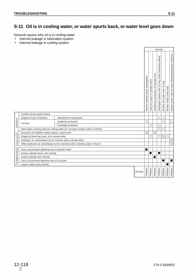
12-118 170-3 SERIES
TROUBLESHOOTING
S-11 Oil is in cooling water, or water spurts back, or water level goes down
General causes why oil is in cooling water • Internal leakage in lubrication system • Internal leakage in cooling system
Confirm recent repair history
Degree of use of machine Operated for long period
Oil level Suddenly increased
Gradually increased
Hard water is being used as cooling water (or corrosion resistor valve is closed)
Excessive air bubbles inside radiator, spurts back
Engine oil level has risen, oil is cloudy white
Hydraulic oil, transmission oil on machine side is cloudy white
When hydraulic oil, transmission oil on machine side is drained, water is found
Qu
estio
ns
Check ite
ms
Carry out pressure-tightness test of cylinder head
Inspect cylinder block, liner directly
Inspect cylinder liner directly
Carry out pressure-tightness test of oil cooler
Inspect water pump directly Tro
ub
lesh
oo
tin
g
Re
pla
ce
Re
pla
ce
Re
pla
ce
Re
pla
ce
Re
pla
ce
Re
pla
ce
Re
pla
ce
Remedy
Bro
ke
n c
ylin
de
r h
ea
d,
he
ad
ga
ske
t
Inte
rna
l cra
cks in
cylin
de
r b
lock
Insu
ffic
ien
t p
rotr
usio
n o
f cylin
de
r lin
er
Da
ma
ge
d c
ylin
de
r lin
er
O-r
ing
, h
ole
s c
au
se
d b
y p
ittin
g
Bro
ke
n o
il co
ole
r co
re,
O-r
ing
Bro
ke
n w
ate
r p
um
p s
ea
l
Bro
ken p
ow
er
train
oil
coole
r (t
rouble
shooting for
machin
e)
Causes
S-11
➀


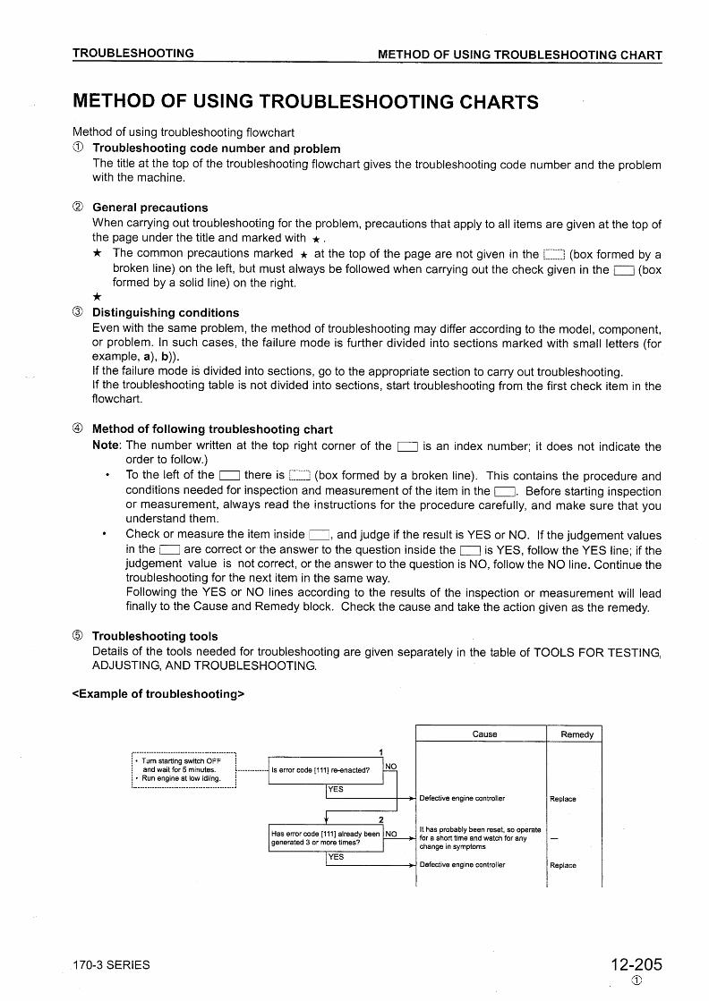
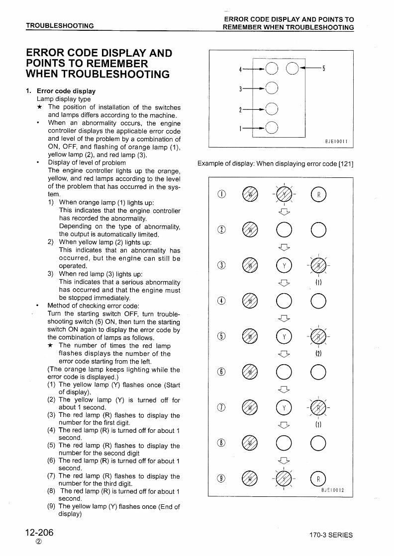


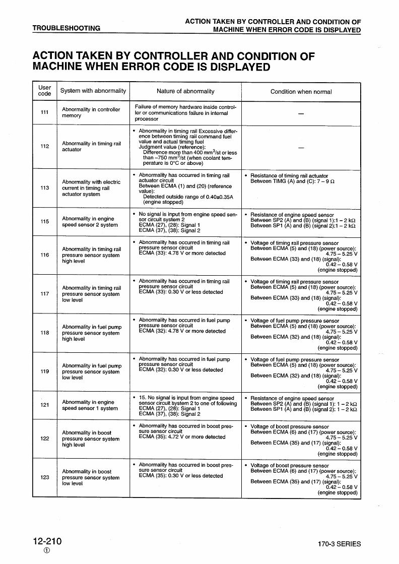


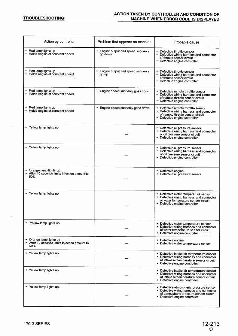


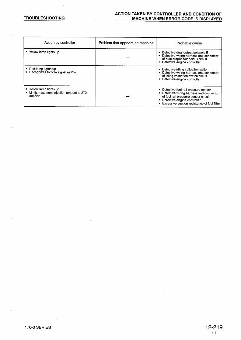


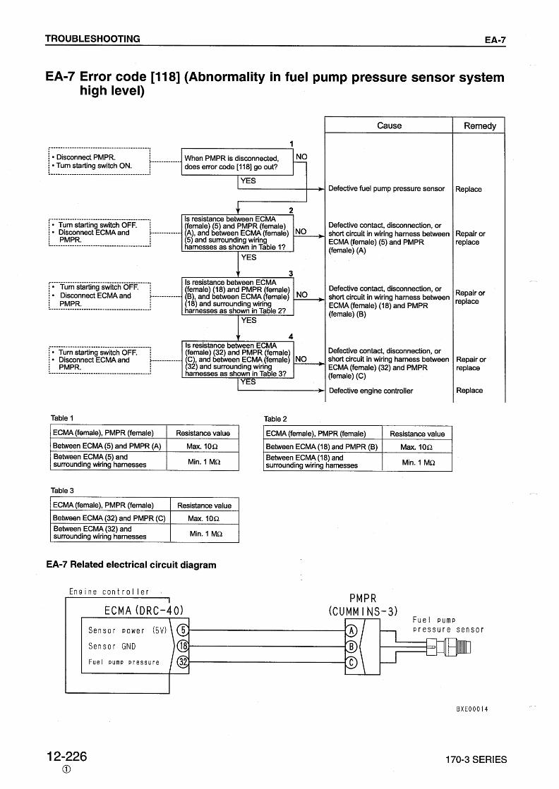
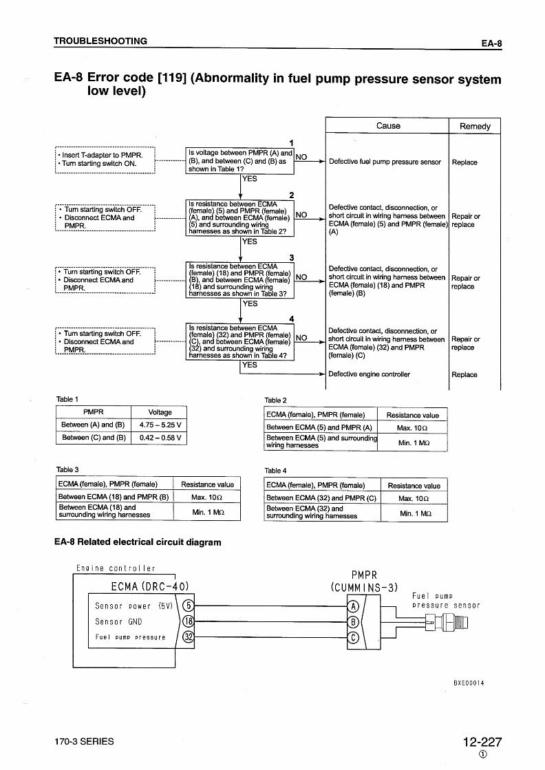


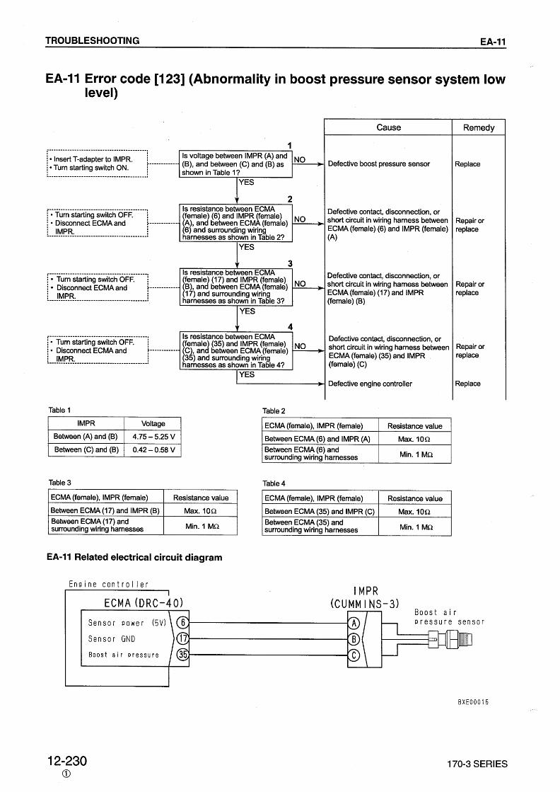


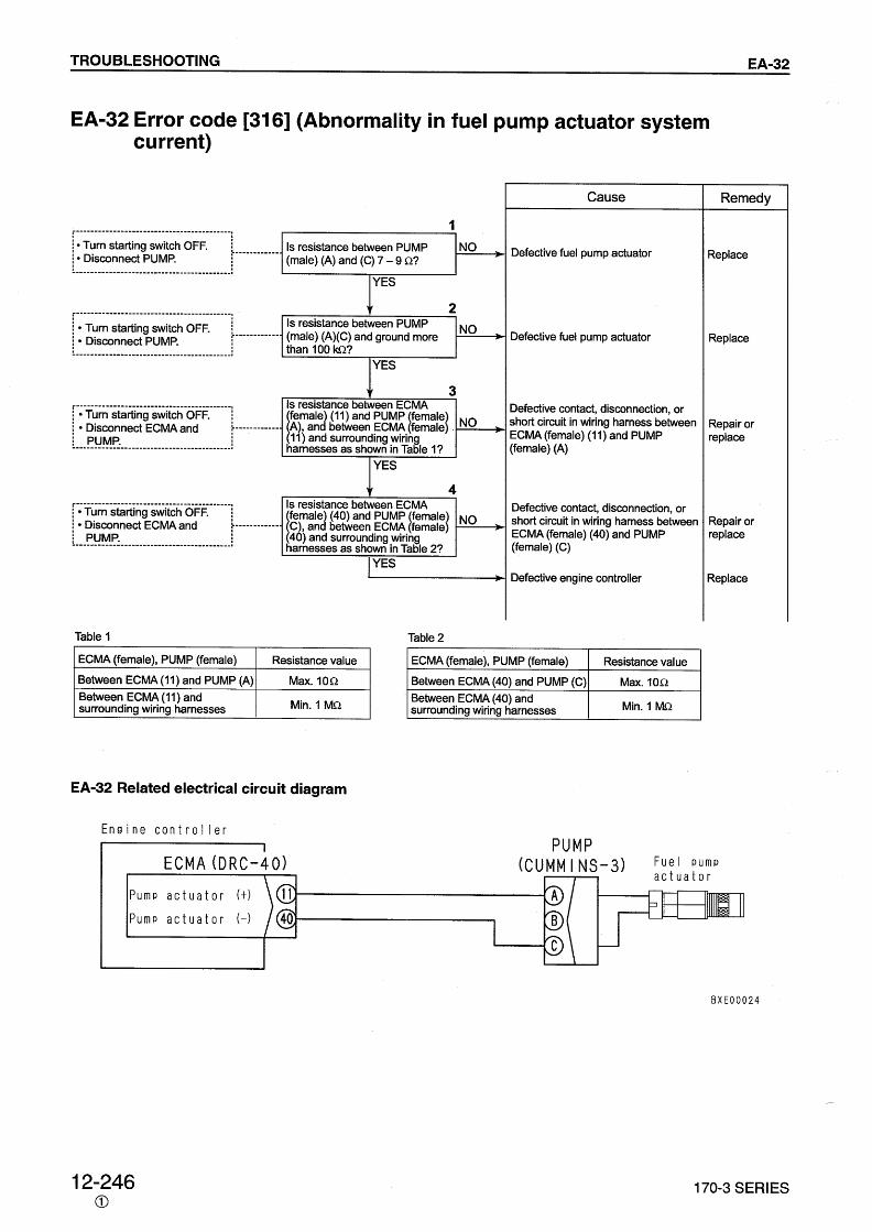


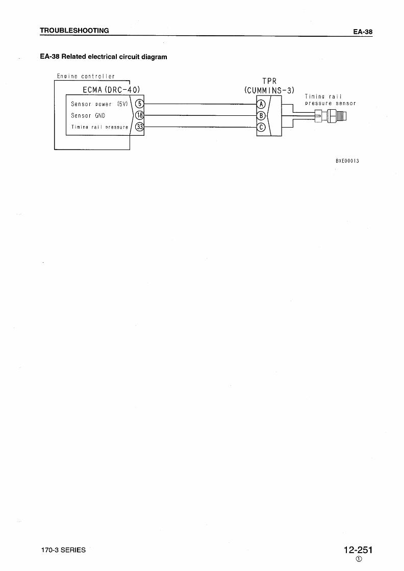


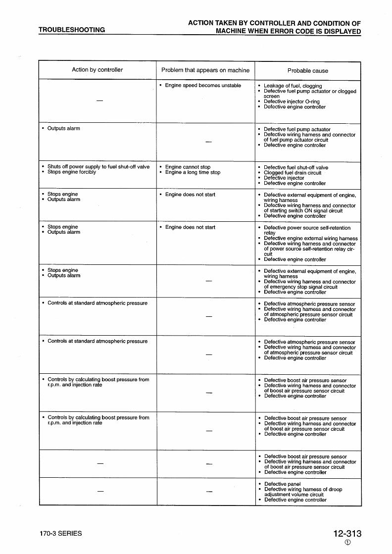


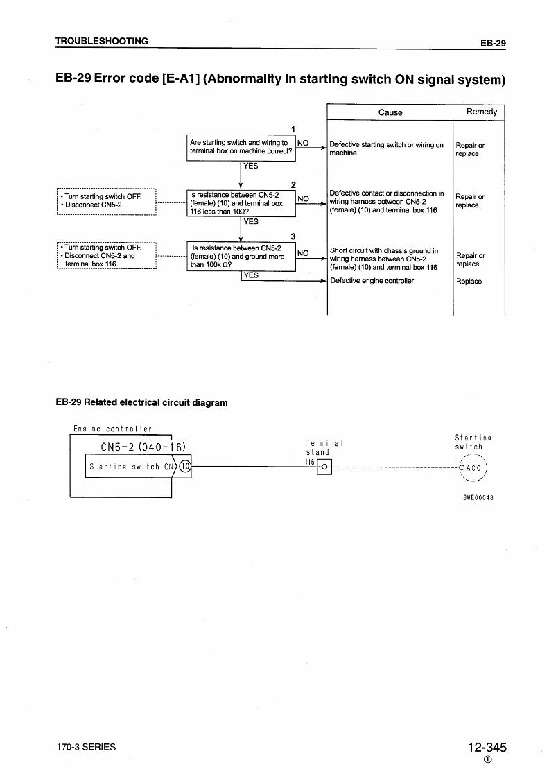
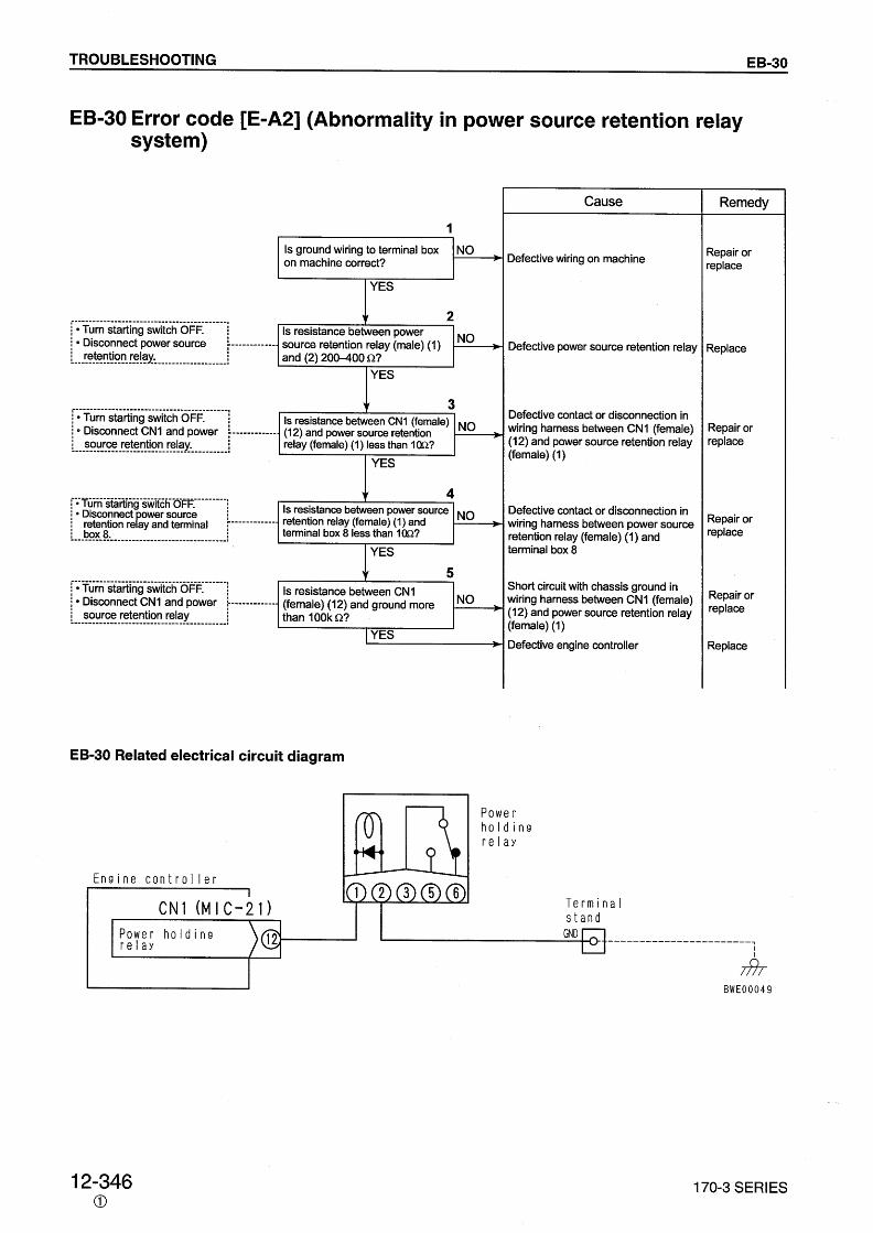


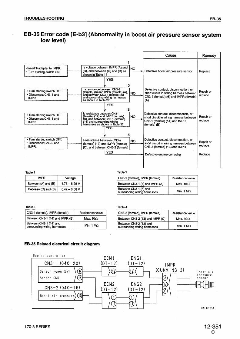
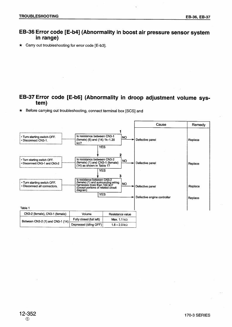


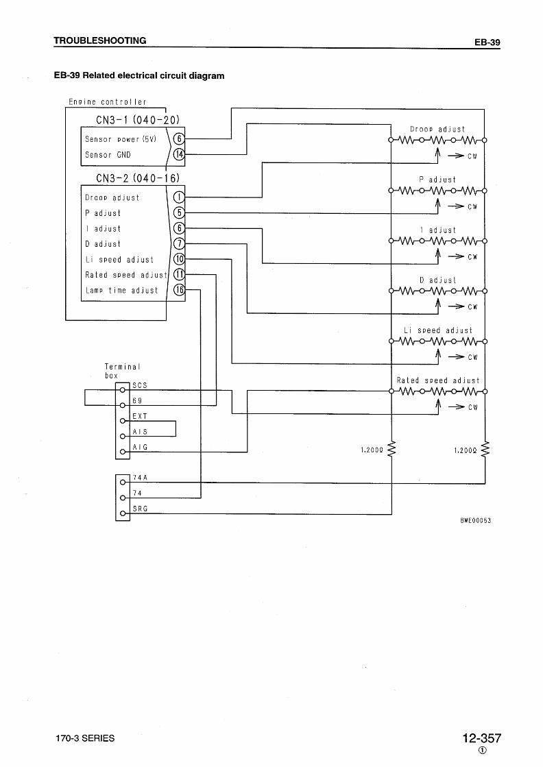


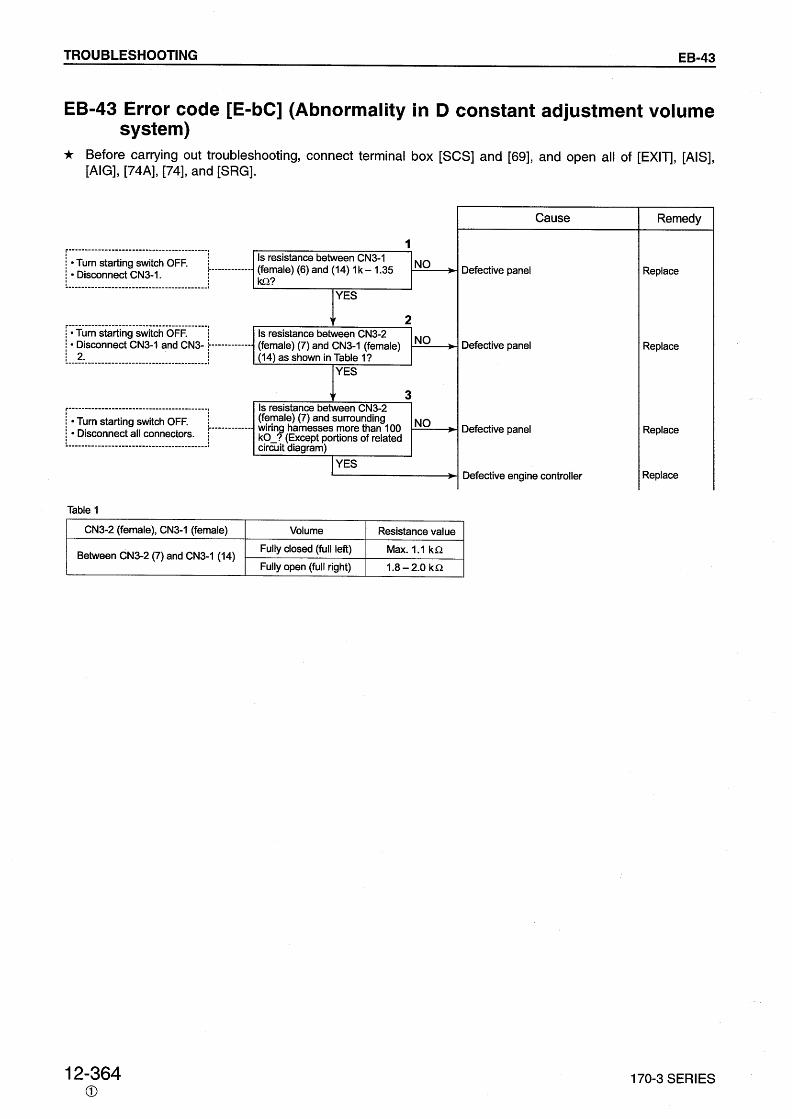


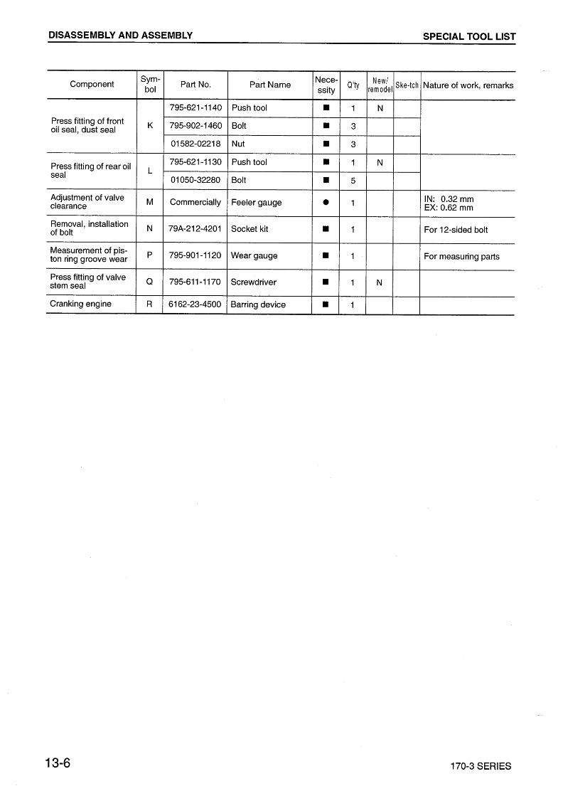
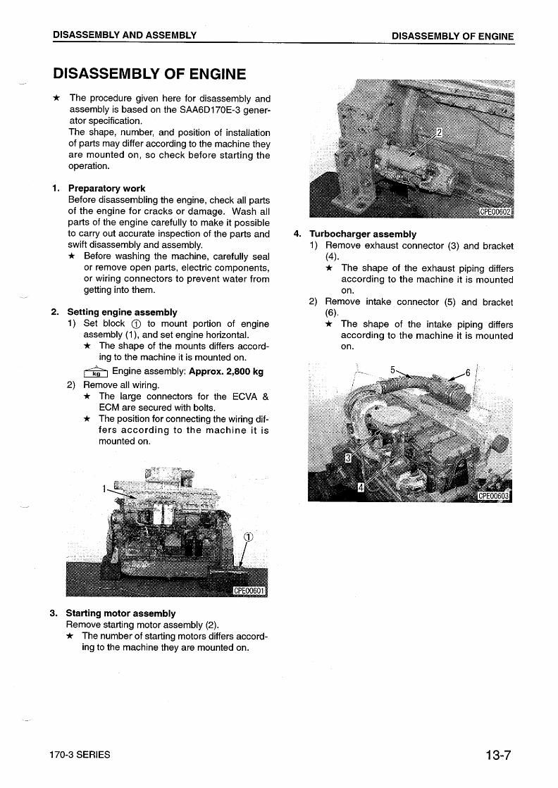
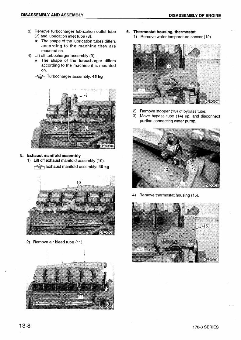


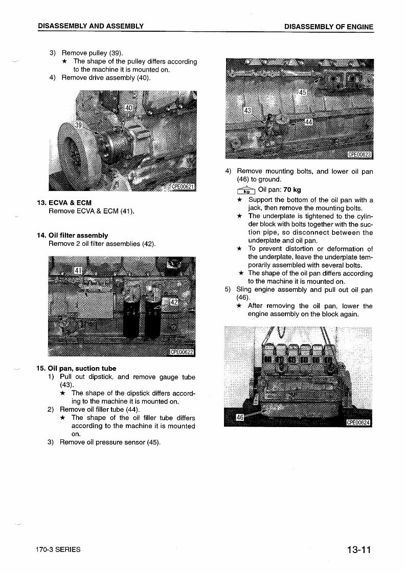


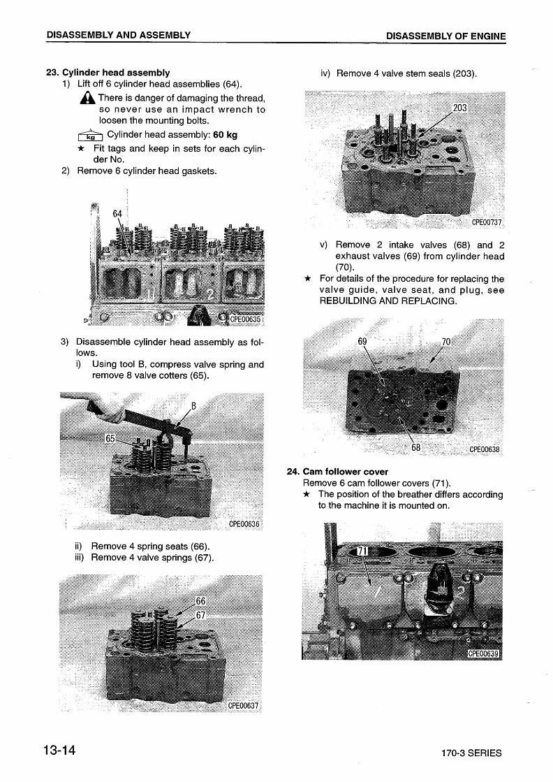


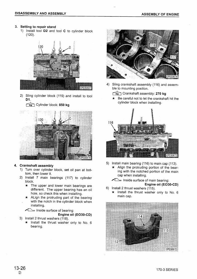

DISASSEMBLY AND ASSEMBLY
170-3 SERIES 13-27
7) Install main cap (113).a Match the bearing numbers for the main
caps, set so that the surface with the [F]mark faces the front of the engine, andinstall.
a Check the number of punch marks on thehead of the mounting bolts. If there arealready 5 punch marks, do not reuse thebolt; replace it with a new part.
Thread portion, seat surface ofmounting bolt:
Engine oil (EO30-CD)Mounting bolt:
1st step: 284 ± 15 Nm 29 ± 1.5 kgm2nd step: 578 ± 10 Nm 58 ± 1.0 kgm3rd step: Tighten 90°
a After tightening the bolts, make 1 punchmark a each on the head of each bolt (donot make a punch mark when using anew bolt).
+30°0
8) Using dial gauge , measure end play ofcrankshaft.a End play: 0.14 0.32 mma If it it not within the standard value, take
the necessary action. For details, seeMAINTENANCE STANDARD.
5. Piston, connecting rod assembly1) Assemble piston and connecting rod assem-
bly as follows.i) Install oil ring (111) to piston (112).a Connect both ends of the expander and
fit in the groove inside the ring.a Align the position of the end gaps as
shown in the diagram.
ASSEMBLY OF ENGINE
(10)


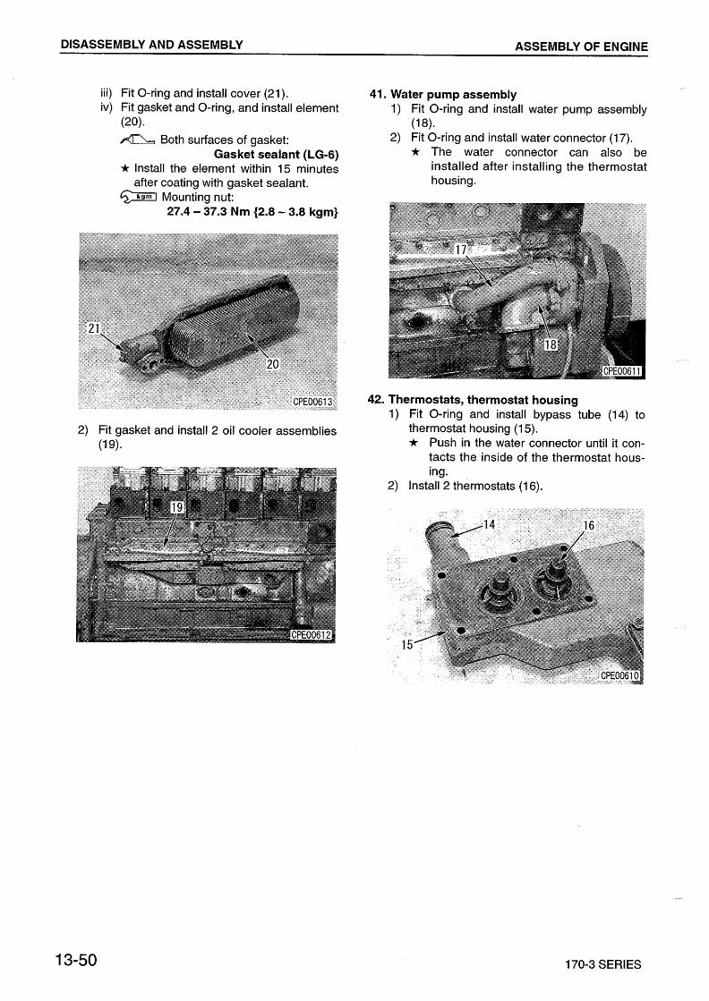


14-2 170-3 SERIES
MAINTENANCE STANDARD
TURBOCHARGER
KTR110L
TURBOCHARGER
(8)

170-3 SERIES 14-3
MAINTENANCE STANDARD
Unit: mm
No. Check item Criteria Remedy
1 End play(play in axial direction)
Standard size Repair limit Replace parts related to thrust0.08 0.13 0.18
2 Radial play(play in radial direction) 0.25 0.44 0.60
Replace parts related to bearing
3 Outside diameter of journal bearing, inside diameter of center housing
Standard sizeTolerance Repair limit
Replace
Shaft Hole Shaft Hole
25 0.0500.067
+0.0210 24.92 25.03
4Inside diameter of journal bearing, outside diameter of wheel shaft 17 0.032
0.043+0.009 0.003 16.95 17.04
Curvature of wheel shaft Repair limit: 0.010 (total deflection of indicator)
5 Thickness of thrust bearingStandard size
Tolerance Repair limit
Width Groove Width Groove
5 0.080.10
+0.020 4.86 5.04
6 Thickness of seal ring
Turbine end
RingStandard size Tolerance Repair limit
2.3 0.080.10 2.15
Groove 2.3 0.01002 2.35
Blower end
Ring 2 0.080.10 1.85
Groove1 Ring 2 0.03
0.04 2.05
2 Ring 4 0.110.12 4.05
7 Clearance between blower housing and impeller Clearance limit: (Min.) 0.20
Replace parts related to bearing
TURBOCHARGER
(8)

14-3-1 170-3 SERIES
MAINTENANCE STANDARD
S500
TURBOCHARGER
(10)

170-3 SERIES 14-3-2
MAINTENANCE STANDARD
Unit: mm
No. Check item Criteria Remedy
1 End play(play in axial direction)
Standard size Repair limit Replace parts related to thrust0.07 0.13 0.18
2 Radial play(play in radial direction) 0.50 0.72 0.92
Replace parts related to bearing
3 Outside diameter of journal bearing, inside diameter of center housing
Standard sizeTolerance Repair limit
Replace
Shaft Hole Shaft Hole
25 0.0500.067
+0.0210 24.92 25.03
4Inside diameter of journal bearing, outside diameter of wheel shaft 17 0.032
0.043+0.009 0.003 16.95 17.04
Curvature of wheel shaft Repair limit: 0.010 (total deflection of indicator)
5 Thickness of thrust bearingStandard size
Tolerance Repair limit
Width Groove Width Groove
5 0.080.10
+0.020 4.86 5.04
6 Thickness of seal ring
Turbine end
RingStandard size Tolerance Repair limit
2.3 0.080.10 2.15
Groove 2.3 0.01002 2.35
Blower end
Ring 2 0.080.10 1.85
Groove1 Ring 2 0.03
0.04 2.05
2 Ring 4 0.110.12 4.05
7 Clearance between blower housing and impeller Clearance limit: (Min.) 0.20
Replace parts related to bearing
TURBOCHARGER
(10)

14-3-3 170-3 SERIES
MAINTENANCE STANDARD
HOLSET
TURBOCHARGER
(10)

170-3 SERIES 14-3-4
MAINTENANCE STANDARD
Unit: mm
No. Check item Criteria Remedy
1 End play(play in axial direction)
Standard size Repair limit Replace related to thrust0.025 0.152
2 Radial play(play in radial direction) 0.254 0.787
Replace related to bearing
TURBOCHARGER
(10)
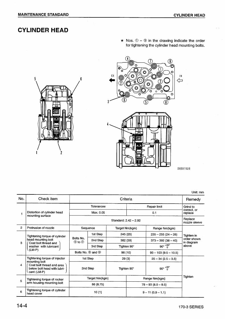

170-3 SERIES 14-5
MAINTENANCE STANDARD
VALVE, VALVE GUIDE
Unit: mm
No. Check item Criteria Remedy
1 Sinking of valveStandard Repair limit Replace
valve or valve seatIntake/exhaust valve 0.39 0.21
(Sinking) (Protrusion) 0.8
2 Thickness of valve lip
Standard size Tolerance Repair limitReplace valveIntake valve 3.2 2.7
Exhaust valve 3.3 2.8
3 Angle of valve seat
Standard Tolerance
Replace
Intake valve 30° ±0° 15
Exhaust valve 45° ±0° 15
4
Outside diameter of valve stem
Intake valve
Standard size Tolerance Repair limit
12
0.0600.080 11.90
Exhaust valve 0.0920.107 11.80
Inside diameter of valve guide 12 0.001
0.019 12.10
5 Protrusion of valve guide 43 ±0.5
6Valve spring
Free length Installed length Installed load Nkg Permissible load Nkg
99.6 87.4 647±6566.0±6.6 55356.4
Perpendicularity of valve spring Repair limit: 2°
VALVE, VALVE GUIDE
(10)
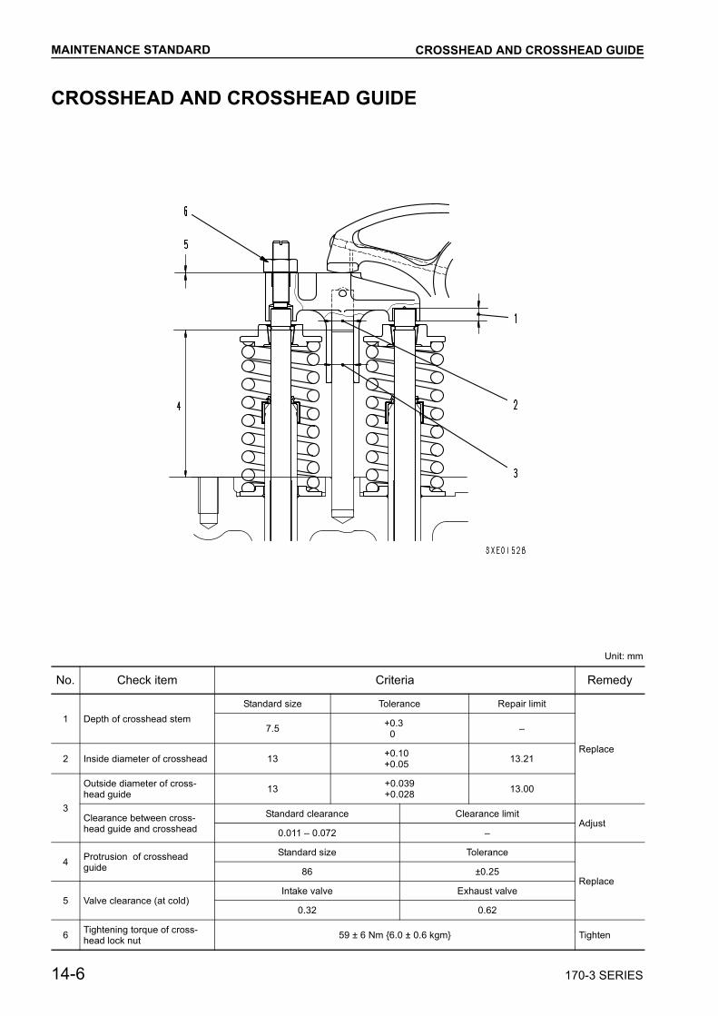
14-6 170-3 SERIES
MAINTENANCE STANDARD
CROSSHEAD AND CROSSHEAD GUIDE
Unit: mm
No. Check item Criteria Remedy
1 Depth of crosshead stemStandard size Tolerance Repair limit
Replace
7.5 +0.30
2 Inside diameter of crosshead 13 +0.10+0.05 13.21
3
Outside diameter of cross-head guide 13 +0.039
+0.028 13.00
Clearance between cross-head guide and crosshead
Standard clearance Clearance limitAdjust
0.011 0.072
4 Protrusion of crosshead guide
Standard size Tolerance
Replace86 ±0.25
5 Valve clearance (at cold)Intake valve Exhaust valve
0.32 0.62
6 Tightening torque of cross-head lock nut 59 ± 6 Nm 6.0 ± 0.6 kgm Tighten
CROSSHEAD AND CROSSHEAD GUIDE


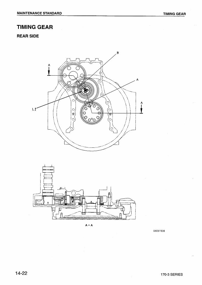

170-3 SERIES 14-23
MAINTENANCE STANDARD
Unit: mm
No. Check item Criteria Remedy
1 Clearance between idler gear bushing and shaft
Standard sizeTolerance Standard
clearance Clearance limitReplace bushing
Shaft Hole
52 0.0270.040
+0.0550 0.027 0.095 0.25
2 Clearance of idler gear in axial direction
Standard clearance Clearance limit Replace thrustbearing0.04 0.18 0.3
Backlash of each gear
Position Measurement place Standard Repair limit
Replace A Crankshaft gear and idler gear (large) 0.155 0.412 0.6
B Crankshaft gear and idler gear (medium) 0.145 0.380 0.6
TIMING GEAR

14-24 170-3 SERIES
MAINTENANCE STANDARD
PISTON, PISTON RING, PISTON PINFCD PISTON TYPE
Unit: mm
No. Check item Criteria Remedy
1Outside diameter of piston
At 3.0 mm from bottom of piston at 20°C
Standard size Tolerance Repair limit
Replace
170(at right angle from boss)
0.1350.165 169.79
2 Piston ring groove
Standard size
Tolerance Clearance limit
clearance from new ring
Link groove Link thickness
Top ring
2nd ring
Keystone
Keystone
Check with piston loop wear gauge or check clearance from new ring
0.15
Oil ring 4.00 +0.05+0.03
0.010.03 0.3
3 Gap in piston ring at end gap
Standard clearance Clearance limit
Top ring 0.50 0.65
1.82nd ring 0.70 0.85
Oil ring 0.50 0.70
4 Inside diameter of piston pin hole
Standard clearance Clearance limit
68 +0.044+0.034
5 Outside diameter of piston pin 68 0.0200.026
PISTON, PISTON RING, PISTON PIN
(12)


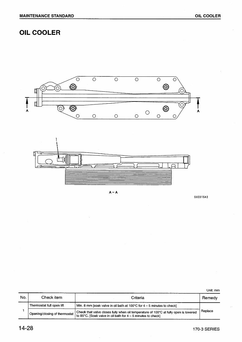


170-3 SERIES 15-1
TABLE OF SPECIAL TOOLS................................... 15- 2TESTING AND INSPECTING CYLINDER HEAD .... 15- 3REPAIRING MOUNTING FACE OF CYLINDER HEAD BY GRINDING .............................................. 15- 6REPLACING VALVE SEAT INSERTS...................... 15- 7PRESSURE TEST METHOD .................................. 15-12REPLACING VALVE GUIDE ................................... 15-13REPLACING CROSS HEAD GUIDE ...................... 15-14GRINDING VALVE .................................................. 15-15TESTING AND INSPECTING CYLINDER BLOCK .................................................................... 15-16GRINDING THE TOP SURFACE OF CYLINDER BLOCK ........................................... 15-19REPLACING MAIN BEARING CAP ........................ 15-25REPLACING CAM BUSHING ................................. 15-27TESTING AND INSPECTING CRANKSHAFT ........ 15-29CORRECTING SURFACE ROUGHNESS OF CRANKSHAFT JOURNAL PORTION ............... 15-31REPAIRING CRANKSHAFT ................................... 15-36TESTING AND INSPECTING OF CONNECTING ROD ......................................... 15-44REPLACING CRANKSHAFT GEAR ....................... 15-46REPLACING CAMSHAFT GEAR ............................ 15-47REPLACING FLYWHEEL RING GEAR .................. 15-48
15 REPAIR AND REPLACEMENT OF PARTS
(7)

REPAIR AND REPLACEMENT OF PARTS
15-2 170-3 SERIES(7)
TABLE OF SPECIAL TOOLS
Operation Symbol Part No. Part Name Q'ty Remarks
Replacing valve seat A
1 795-100-4801 Puller 1 For valve seat
2 795-100-3005 Seat cutter 1
3795-611-1410 Push tool 1 For intake valve
795-611-1420 Push tool 1 For exhaust valve
Pressure test of cylinder headE 795-611-1500 Coolant tester 1
F 79A-471-1050 Pump assembly 1
Replacing valve guide G1 795-611-1610 Valve guide remover 1
2 795-611-1620 Valve guide driver 1
Replacing crosshead guide H 795-611-1700 Crosshead guide pulle1
1
Grinding valve I Commercially available Valve refacer 1
Replacing cam bushing J1 795-621-1600 Push tool set 1
2 792-103-0400 Grip 1
Replacing crankshaft gear K1 790-101-2800 Bearing puller 1
2 790-101-2300 Push puller 1
TABLE OF SPECIAL TOOLS

170-3 SERIES 15-3
REPAIR AND REPLACEMENT OF PARTS
TESTING AND INSPECTING CYLINDER HEAD
1. Valve guide2. Closshead guide3. Fuel injection nozzle sleeve4. O-ring5. Cylinder head6. O-ring7. Pushrod tube8. Valve seat insert
(7)
TESTING AND INSPECTING CYLINDER HEAD

REPAIR AND REPLACEMENT OF PARTS
15-4 170-3 SERIES
TESTING AND INSPECTING
Unit: mm
Inspection item Judgement standards Remedy
A. Cracks, leakage from cylinder head
• Check for cracks (ext ernal color check)• Check for water leakage with air pressure test
(294 – 343 kPa 3.0 – 3.5 kg/cm2, 30sec.)• Water pressure test (294 – 343 kPa 3.5 – 4.0 kg/cm2, 10 min.)
Replace
B. Distortion of top, bot-tom surface of cylin-der head
• Tolerrance : 0.1 Grind to correct
C. Damage to injec-tion nozzle seat surface, contact width
Machine to repair or replace
D. Protrusion of injector Replace cylinder head or injector
E. Damage to valve seat surface or loosening of seat
• Dent of seat surface• Check contact between valve and seat surface• Airtighteness test• Tap cylinder head and chek for looseness
Correct seat sur-face or replace valve seat
F. Sinking and protrusion of valve (both intake and exhaust)
Replace valve or valve seat
G. Thickness of valve head Replace
Permissible range: 2.42 – 2.92
Standard value Repair limit
-0.39 (sinking) to 0.21(protrusion) -0.80 (sinking)
• Thickness of valve head
• Angle of seat surface "a"Intake valve: 30°Exhaust valve: 45°
Standard value Repair limit
Intake valve 3.2Exhaust valve3.3
2.72.9
(7)
TESTING AND INSPECTING CYLINDER HEAD
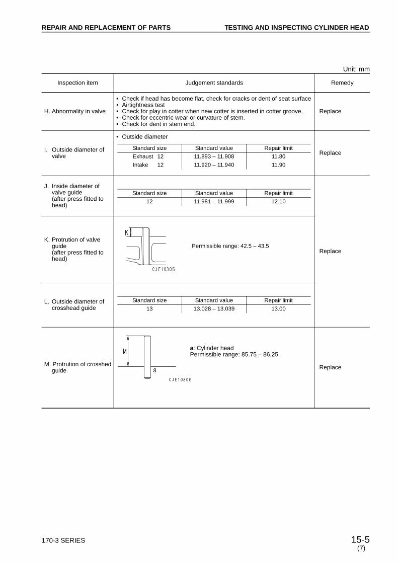
170-3 SERIES 15-5
REPAIR AND REPLACEMENT OF PARTS
Unit: mm
Inspection item Judgement standards Remedy
H. Abnormality in valve
• Check if head has become flat, check for cracks or dent of seat surface• Airtightness test• Check for play in cotter when new cotter is inserted in cotter groove.• Check for eccentric wear or curvature of stem.• Check for dent in stem end.
Replace
I. Outside diameter of valve
• Outside diameter
Replace
J. Inside diameter of valve guide(after press fitted to head)
Replace
K. Protrution of valve guide(after press fitted to head)
L. Outside diameter of crosshead guide
M. Protrution of crosshed guide Replace
Standard size Standard value Repair limit
Exhaust 12 11.893 – 11.908 11.80
Intake 12 11.920 – 11.940 11.90
Standard size Standard value Repair limit
12 11.981 – 11.999 12.10
Permissible range: 42.5 – 43.5
Standard size Standard value Repair limit
13 13.028 – 13.039 13.00
a: Cylinder headPermissible range: 85.75 – 86.25
(7)
TESTING AND INSPECTING CYLINDER HEAD

REPAIR AND REPLACEMENT OF PARTS
15-6 170-3 SERIES(7)
REPAIRING MOUNTING FACE OF CYLINDER HEAD BY GRINDING
1. Grinding1) Remove the valve seat inserts. For details,
see REPLACING VAVLE SEAT INSERTS.2) Remove the nozzle holder sleeves. For
details, see REPLACING NOZZLE HOLDERSLEEVES.
3) Grind the cylinder head to remove thestrained or corroded portions within the limitof the height of the cylinder head (H).If any grinding is carried out, stamp the sideface of the cylinder head with an (R) mark.a Repair limit of cyinder head height (H):
150.65 mm(Standard size:150.95 – 151.05 mm)
a Amount to remove per grinding:0.10 – 0.15 mm
a Surface roughness of grinding surface:Top surface: 12.5SUnder surface: 4S
a Flatness (deformation): Max. 0.05 mm a Grinding limit: 0.3 mma Difference in head height between 6 cyl-
inders: Max. 0.15 mm4) Press-fit the one-size-larger inserts. For details,
see REPLACING VALVE SEAT INSERTS.5) Press-fit the nozzle holder sleeves. For details,
see REPLACENG NOZZLE HOLDERSLEEVES.
2. Check after grinding• Check the sinking of the valves and protrution of
the injector are within the standard valuesa Standard sinking of valves:
(sinking) 0.39 – (protrution) 0.21 mma Allowable protrusion of injector:
3.7 – 4.3 mm
REPAIRING MOUNTING FACE OF CYLINDER HEADBY GRINDING

170-3 SERIES 15-7
REPAIR AND REPLACEMENT OF PARTS
REPLACING VALVE SEAT INSERTS
a When repairing without replacing the valve seatinsert (when there is surface roughness orstepped wear), repair with the amount of sinkingof the valve is within the repair limit.
a Machining drawings of new valve seat inserts isshown in the right.
a Checking for looseness of valve seat insert Tap the outside of the valve insert of the cylinderhead with a hammer to check for any loosenessof the valve seat insert. If the valve seat insert isloose or springs back, replace the insert.
1. Pulling out the valve seat insert1) Using the grinder of valve e seat puller A1,
make grooves on the inserts to pull them outaccording to the following procedure.
a Set the air pressure to 490 – 588 kPa 5 to 6kg/cm2.
a When replacing the grindstone of the grinder,shut off the compressed air.
k Before using the grinder, run it for oneminute to check abnormality. a After replacing the grindstone, run the
grinder for three minutes to test it.
k Confirm that the grindstone is not dam-aged, then install it to the shaft of thegrinder without applying excessive force.Confirm that there is no play between thegrindstone and shaft.
k When using the grinder, wear safety gog-gles.
i) Install grindstone [5] to grinder [1].ii) Install the sleeve and grinder after align-
ing the groove of sleeve [3] with holder[2].
a Adjust the position of the grinder with setscrew [4].
• Intake valve
• Exhaust valve
Item Intake valve Exhaust valveSeat surface angle (a) 30° 45°
Finish width (b) 3.5 mm 4 mm
Inside diameter (c) 62 ± 0.05mm 60.4 ± 0.05mm
Inside diameter (d) – 53 mm
Seat surface roughness Max. 3.2 S
(7)
REPLACING VALVE SEAT INSERTS

REPAIR AND REPLACEMENT OF PARTS
15-8 170-3 SERIES(7)
iii) Adjust the position of the grinder so thatthe center of grindstone [5] will be at thecenter of insert (1), then tighten the setscrew to secure the grinder.
iv) Fully open the throttle of the grinder torotate the grindstone and slowly move ituntil it contacts insert (1).
v) Press the grindstone against the insideof the insert, move it in a circular pattern.a Make a groove about 1 mm deep.
2) Pull out the insert with the puller head ofvalve seat puller A1 according to the follow-ing procedure.i) Push three claws (a) of puller head [6]
inward by hand and put them in insert(1).
ii) Tighten screw [8] to press the threeclaws against the groove on the insidesurface of the insert. a If the screw is tightened too strongly,
the insert will break and it will be diffi-cult to pull it out. Therefore, stoptightening the screw when the clawscompretely contact the groove.
iii) Place bridge [9] over the puller head,then place plates [10] and [11] on thebridge. tighten nut [12] to pull out theinsert.
REPLACING VALVE SEAT INSERTS

170-3 SERIES 15-9
REPAIR AND REPLACEMENT OF PARTS
2. Machining valve seat insert mounting hole tooversize1) Using valve seat cutter A2, machine the
mounting hole to install a one-size-largerinsert• Dimensions of insert and mounting hole
a: Bottom surface of cylinder head
R: 0.6 mm
• Intake valve side Unit: mm
• Exhaust valve side Unit: mm
a Inside diameter surface roughness: Max. 12.5S
a Mounting hole bottom roughness:Max. 12.5Sa Concentricity of inside diameter of valve
guide and inside diameter of insert hole: 0.07 mm (T.l.R) max.
a Rectangularity of inside diameter of valveguide and bottom of insert hole:
Max. 0.03 mm (T.l.R)
Stamp on
insert
Insert Mounting hole for insert
O.D.(d1) Hight (h1) I.D. (d2) Depth
(h2)
S.T.D. 64.00 8.5 64.00 11.4±0.1
0.25 O.S 64.25 8.5 64.25 11.4±0.1
0.50 O.S 64.50 8.62 64.50 11.52±0.1
0.75 O.S 64.75 8.75 64.75 11.65±0.1
1.00 O.S 65.00 8.88 65.00 11.78±0.1
Stamp on
insert
Insert Mounting hole for insert
O.D.(d1) Hight (h1) I.D. (d2) Depth
(h2)
S.T.D. 63.60 9.7 63.60 12.3±0.1
0.25 O.S 63.85 9.7 63.85 12.3±0.1
0.50 O.S 64.10 9.82 64.10 12.42±0.1
0.75 O.S 64.35 9.95 64.35 12.55±0.1
1.00 O.S 64.60 10.08 64.60 12.68±0.1
0- 0.1
+0.105+0.080
+0.10
+0.0190
+0.105+0.080
+0.10
+0.0190
+0.105+0.080
+0.10
+0.0190
+0.105+0.080
+0.10
+0.0190
+0.105+0.080
+0.10
+0.0190
+0.100+0.080
+0.10
+0.0190
+0.100+0.080
+0.10
+0.0190
+0.100+0.080
+0.10
+0.0190
+0.100+0.080
+0.10
+0.0190
+0.100+0.080
+0.10
+0.0190
(7)
REPLACING VALVE SEAT INSERTS

REPAIR AND REPLACEMENT OF PARTS
15-10 170-3 SERIES(7)
3. Press fitting the insert1) Using insert push tool A3, press-fit the insert
(1).
2) Check the sinking distance a of the insertfrom the mounting surface of the cylinderheada Srandard sinking distance a of insert:
2.8 – 3.1 mm
4. Finishing the seat surface1) Finish the seat surface with valve seat cutter
A2 as shown in the figure.
a Connectricity of valve guide and insert:Max. 0.07 mm (T.I .R)
2) Fit the seat surface using the compound.i) Coat the seat surface of the valve thinly
with a rough compound mixed with oilinsert it in the valve guide that forms apair with that valve, then fit a rubbing barto the valve head, and turn it with bothhands to rub lightly against the valveseat.
ii) When the rubbing removes the rough-ness, wipe off the compound. Then coatwith a fine compound and repeat theabove process to give a good contactsurface with no break in contact.
• Intake valve
• Exhaust valve
Item Intake valve Exhaust valve
Seat surface angle (a) 30° 45°
Finish width (b) 3.5 mm 4 mm
Inside diameter (c) 62 ± 0.05mm 60.4 ± 0.05mm
Inside diameter (d) – 53 mm
Seat surface roughness Max. 3.2 S
REPLACING VALVE SEAT INSERTS

170-3 SERIES 15-11
REPAIR AND REPLACEMENT OF PARTS
5. Final checka Sinking and protrusion amount C of valve
(1): (sinking) 0.39 – (protrusion) 0.21mma: Intake sideb: Exhaust sided: Bottom surface of cylinder head
• Coat the seat surface of the new valve thinlywith red lead (minium), insert it in the valveguide, push lightely against the valve insertsurface, and rotate 10°. Check the valveinsert contact surface, and confirm that thecontact is uniform without any breaks.
• or Mark marks d (about 20 places)with a pencilon the seal surface of the new valve asshown in the diagram, insert it in the valveguide, push lightly against the valve insertsurface, and rotate 10°. Check that the pencilmarks have been erased uniformly aroundthe whole circumference.
Airtightness testing with vacuum tester • When carrying out an airtightness test with a
vacuum tester, test as follows1) Wipe off all the dirt, dust, and oil from the
valve and valve seat surface with a cloth.2) Assmble the valve, valve spring, retainer,
and cotter, tap the tip of the valve stem with aplastic hammer 2 or 3 times directly fromabove to bring it into tight contact with theseat sutface.
3) Fit a vacuum cup that matches the size ofthe valve in tight contact with the head sur-face. When doing this, to improve the air-tightness of the vacuum cup, coat grease onthe O-ring fitted to the vaccum cup, and fit itin tight contact with the flat surface of thehead.(Be careful not to get any grease on the seatsurface.)
4) Set the vacuum gauge to 93.3 kPa 700mmHg, and check that the pressure dropsless than 1.3 kPa 10 mmHg in 3 seconds.If it drops more than 1.3 kPa 10 mmHg in 3seconds, check for any dirt on the seat sur-face, or rub the surface to correct it.
(7)
REPLACING VALVE SEAT INSERTS

REPAIR AND REPLACEMENT OF PARTS
15-12 170-3 SERIES(7)
PRESSURE TEST METHOD
• If the area around the head has been corrected,test as follows.
1. Water pressure test1) Assemble tool E and tool F, and connect a
hose to frange (1).
a Block air vent (2) with the following parts.• 07037 – 11012 Plug• 07000 – 02012 O-ring
2) Apply water pressure 343 – 392 kPa 3.5 –4.0 kg/cm2 for approx. 10 minutes, andcheck for any leakage from around the head.
a It is preferable to warm the whole cylinderhead and carry out the test with hot water (82– 93°C).
2. Air pressure test1) Connect the pump hose to flange (1).2) Place the head in a water bath, apply air
pressure 343 – 392 kPa 3.0 – 3.5 kg/cm2for approx. 30 seconds, and check for any airleakage in the water.
a If the above test shows that there are cracks,replace the cylinder head.
PRESSURE TEST METHOD

170-3 SERIES 15-13
REPAIR AND REPLACEMENT OF PARTS
REPLACING VALVE GUIDE
1. Removing the valve guide• Remove the valve guide with valve guide
remover G1.
2. Press-fitting the valve guide1) Press-fit the valve guide until the tip of valve
guide driver G2 contacts the cylinder head.2) Confirm that the protrusion of the valve guide
is within specification.a Protrusion of valve guide: 43 ± 0.5 mma Inside diameter of valve guide hole in cylin-
der head: 19 mm+0.0210
(7)
REPLACING VALVE GUIDE

REPAIR AND REPLACEMENT OF PARTS
15-14 170-3 SERIES(7)
REPLACING CROSS HEAD GUIDE
1. Removing the cross head guide• Using cross head guide puller H, pull out the
cross head guide from cylinder head (1).1) As show in the figure, hold the cross head
guide with collect [5] of the puller.2) Tighten the collect with bolt [1] to lock sleeve
[2].3) Rotate nut [3] and pull out the cross head
guide.4) Remove burrs, fins, etc. from the mounting
place of the cross head guide and clean it.
2. Press-fitting the cross head guide• Insert the cross head guide in the cylinder head,
then hit it into the cylinder head with a copper baror plastic hammer until its protrusion is withinspecification.a Protrusion of cross head guide Toletance:
86 ± 0.25 mma Inside diameter of crosshead guide hole:
13 mm+0.008- 0.010
REPLACING CROSS HEAD GUIDE

170-3 SERIES 15-15
REPAIR AND REPLACEMENT OF PARTS
GRINDING VALVE
1. Grinding the seat surface• Grind the seat sutface with valve refacer I.
a Angle of valve seat: intake valve: 30°EXhaust valve: 45°
2. Checking after grinding• Confirm that the thickness of the valve head,
protrusion of the valve, and the contact surfaceof the valve seat are within specification.
a Thickness of valve headRepair limit
Intake valve: 2.7 mm(Standard size 3.2 mm)
Exhaust valve: 2.9 mm(Standard size 3.3 mm)
a Sinking of valve Standard: (sinking) 0.39 – (protrusion) 0.21 mm
Repair limit: (sinking) 0.8mm
a Check the contact of the valve with the seatsurface using one of the following methods.• Coat the seat surface of the ground valve
thinly with red lead (minium), insert it inthe valve guide, push lightly against thevalve seat insert surface, and confirmthat the contact is uniform without anybreaks.
• Make marks a with a pencil on the seatsurface of the ground valve as shown inthe diagram, insert it in the valve guide,push lightly against the valve seat insertsurface, and rotate 10°. Check that thepencil marks have been erased uniformlyaround the whole circumference.
(7)
GRINDING VALVE

REPAIR AND REPLACEMENT OF PARTS
15-16 170-3 SERIES(7)
TESTING AND INSPECTING CYLINDER BLOCK
1. Cylinder liner2. Crevice seal3. O-ring4. Cylinder block5. Main bearing cap6. Main bearing cap bolt7. Camshaft bushing
TESTING AND INSPECTING CYLINDER BLOCK

170-3 SERIES 15-17
REPAIR AND REPLACEMENT OF PARTS
TESTING AND INSPECTING
Unit: mm
Inspection item Judgement standards Remedy
A. Cracks • Check for cracks (external color check)• Cylinder head bolts hole portion, etc. Replace
B. Correction of contact at packing portion Replace
C. Clearance between liner and cylinder block
Replace cylinder liner or block
D. Inside diameter of camshaft bushing
• Inside diameter
• Clearance between camshaft bearing and cylinder block Standard clearanceStandard valve
Replace bushing
E. Protrusion of linerReplace cylinder liner or correct cylinder block
F. Depth of counter-bore and corro-sion of bot-tom surface
Repair by machining, add shim
Check for water leakage caused by corrosion
Standard size
Standard valveStandard
ClearanceInside diame-ter of block
Onside diam-eter of liner
190.4 190.34 – 190.40 190.19 – 190.29 0.05 – 0.21
Standard size Standard valve Repair limit
105 105.017 – 105.101 105.130
Standard clearance Standard valve
0.059 – 0.173 0.24
Permissible range: 0.07 – 0.15
a: Cylinder blockb: Cylinder liner
• Check for corrosion
Standard size Standard value
14 14.00 – 14.05
(7)
TESTING AND INSPECTING CYLINDER BLOCK

REPAIR AND REPLACEMENT OF PARTS
15-18 170-3 SERIES(7)
Unit: mm
Inspection item Judgement standards Remedy
G. Distortion, wear of cyl-inder head mounting surfac
Repair by machining
H. Inside diameter of main bearing mounting hole
• Tighten main bearing cap bolt with speci-fied torque
Replace
I. Fitting of cap and cylin-der block(Interference)
• Standerd Interface: 0.080 – 0.159
J. Inside diameter of counterbore, outside diameter of cylinder liner flange
Replace cylinder liner
Replace cylinder block
Standard size Repair limit
Overall top surface of block: Max. 0.09For one cylinder: Max. 0.05
0.150.15
Standard size Standard valve Repair limit
148 (without bearing) 148.000 – 148.025 –
Cylinder linerCylinder
linerStanderd
sizeStanderd
valveRepair
limit
c Top 206.0205.965
–206.015
–
d Bottom 194.5194.565
– 194.615
–
Cylinder blockCylinder
blockStanderd
sizeStanderd
valveRepair
limit
c Top 206.0 205.93 – 205.99
205.92 – 206.02
d Bottom 194.5 194.48 – 194.54
194.46 – 194.57
TESTING AND INSPECTING CYLINDER BLOCK

170-3 SERIES 15-19
REPAIR AND REPLACEMENT OF PARTS
GRINDING THE TOP SURFACE OF CYLINDER BLOCK
GrindingGrind off the strained and corroded portions of thecylinder block within the allowable height (H) of thecylinder block.
a Use the following as a guide to decide whento grind to the top surface.If the top surface of the cylinder block is wornor corroded in the shape of the head gasket,and the amonut of wear a is more than 0.10mm, grind the top surface.
a If there are blackened portions on the cylin-der liner contact surface of the counterbore b(particularly in the front-to-rear direction), orthere is speckled wear, and these portionsextend over more than half of the contactwidth of the deck, and if grinding has beencarried out on th top surface, correct thecounterbore.
1. Grinding top surface1) Measure the wear and strain of the tops sur-
face of the cylinder block, and if it is notwithin the repair limit, grind the top surface.Flatness of cylinder block:
Standard dimension: 0.05 mmRepair limit: 0.10 mm (for one cylinder)
Height of cylinder block (H):Standard dimension:
488.96 – 489.04 mmRepair limit: 488.56 mm
Roughness of top surface of cylinder block:Max. 12.5S
If grinding with a grindstone (for reference)a Speed of grindstkone: 1,650 – 1,950
m/min.a Speed of table: 15 – 30 m/min.a Grinding depth/time: 0.025 mma Cross feed/time: 1 – 2 mma Grindstone: A461Va Grinding lubricant: Water-soluble
grind-ing lubricant
(7)
GRINDING THE TOP SURFACE OF CYLINDER BLOCK

REPAIR AND REPLACEMENT OF PARTS
15-20 170-3 SERIES(7)
2. Grinding couterboreAfter grinding the top surface of the cylinderblock a , measure the depth of the counterbore.If it is not within the standard dimension, or ifthere are blackened portions on the cylinder linerb contact surface of the counterbore (patricularlyin the front-to-rear direction), or there is speckledwear, and these portions extend over more thanhalf of the contact width of the deck, correct thecounterbore depth L within the repair limit. Aftercorrecting, if the counterbore depth is within14.05 – 15.525 mm, combine with shims andadjust so that the liner protrusion "l" is 0.07 –0.15 mm.a Counterbore depth L:
Standard dimension 14 mmRepair limit: 15.46 mm
a Protrusion of cylinder liner "l" :Standard value: 0.07 – 0.15 mm
a Roughness of counterbore: Max. 12.5S (Seediagram on the right)
a Machined shape: (See diagram on the right)• Machine only the shaded area to adjust the
depth of part c of the counterbore.• Machining dimension of part d: Max. 0.4 mm• Machining dimension of part e: Max. 0.7 mm• Machining dimension of part f:
0 – Max. 0.06 mm• Angle of part g to center (straight line) of cyl-
inder: 90°• Remove burrs from the tapered parts, etc.• Letter h indicates the center of the cylinder.• Set R to 0.2 – 0.4 mm.For the extra amount for counterbore depth L,decide the machining amount so that the protru-sion of the cylinder liner will be within the stan-dard value.When grinding within the repair limit when coun-terbore depth L exceeds the standard dimen-sion, set the machining amount so that 1 of theshims (1) shown below will be used for each cyl-inder.
[Reference] Adjustment shims for counterbore depthUnit: mm
a Inside diameter j and outside diameter I ofshims (1)• I: 205.5 ± 0.15 mm• j: 194.6 mm
Part No. T t Weight(kg) Remarks
6162-29-2260 1.50 0.025 0.0046162-29-2250 0.80 0.025 0.002
6162-29-2240 0.50 0.025 0.0016162-29-2230 0.26 0.025 0.0016162-29-2220 0.20 0.020 0.001
6162-29-2210 0.16 0.016 0.001
+0.050
+30’0
+0.0300
GRINDING THE TOP SURFACE OF CYLINDER BLOCK

170-3 SERIES 15-21
REPAIR AND REPLACEMENT OF PARTS
3. Checking and distinguishing after grindingand correctingAfter grinding and correcting, check for scratcheson the flat surface around the water and oil holesin the cylinder block top surface.Remove all burrs completely.After grinding the top surface, if the cylinderblock height H exceeds the standard dimension,but is within the repair limit (488.56 – 488.96mm), always use an oversize head gasket.a Oversize head gasket part number:
6240-19-1810Thickness of plate: 2.4mm
(standard: 2.0mm)a To distinguish, the letters "OS" are stamped
on the plate.After correcting, stamp the top surface of the cyl-inder block a according to the content of the cor-rection as shown in the table below.a The arrow in the figure indicates the flywheel
side of the cylinder block.
Talbe of letters to stamp
(Size of letters: 5 – 10mm)
Oversize head gaske Shim Stamp
Par
ts u
sed
for
corr
ectio
n – – Not needed
Q – OS
– Q SH
Q Q WS
(7)
GRINDING THE TOP SURFACE OF CYLINDER BLOCK

REPAIR AND REPLACEMENT OF PARTS
15-22 170-3 SERIES(7)
4. Procedure for coating gasket sealant to cylin-der block counterbore When pulling out the cylinder liner and press fit-ting it again, coat gasket sealant LG-6 to the con-tact surface of the liner flange as follows. Use thesame procedure when using a shim for the cor-responding part.a The following commercially available seal-
ant is equivalent to LG-6.• Three Bond: TB1215• Nihon Hermetic: SS-60F
1) Use a cloth to wipe off all the dirt and oil fromthe contact surface of the liner flange andcylinder block counterbore.
2) Coat the position marked a in the diagramwith LG-6.• Make the diameter of the line of gasket
sealant 2 – 3 mm.• Make the overlapping portion b for begin-
ning and ending the coating of sealant 6± 6mm as shown in the diagram.c: Top surface of cylinder blockd: Mating portion of cylinder liner
a When using shimsi) Thinly coat underside e of shim (1)
with LG-6, and then fit the shim to thedeck of the block.
ii) Similarly to the case where no shimsare used, coat the position marked awith LG-6.
3) Press fit the liner in the cylinder block.When doing this, coat the seal and O-ringwith rubber lubricant RF-1.a RF-1 is equivalent to the commercially
available Daido Kagaku Kogyo DS-50.a If RF-1 is not available, coat the O-ring
and sea l con tac t su r face w i th anextremely small amount of engine oil(SAE30) immediately before press fittingthe liner.
GRINDING THE TOP SURFACE OF CYLINDER BLOCK

170-3 SERIES 15-23
REPAIR AND REPLACEMENT OF PARTS
4) Coat the liner O-ring, clevis seal, and cylin-der block contact surface with a smallamount of engine oil (SAE = 30) immediatelybefore press fitting the liner.
a Coat the contact surface of the cylinder blockuniformly around the whole circumference byhand.
5) Insert liner (1) facing liner top face stamp"GN" to front into the cylinder block, takingcare not to damage the O-ring.
6) Use your weight and push the liner in withboth hands.
a If the liner does not go in smoothly when youapply your weight, there is danger that the O-ring may be damaged, so check the cylinderblock for burrs or flashes.
7) Using liner driver I, press fit cylinder liner (1)into the cylinder block.
a Using the following procedure, squeeze outthe gasket sealant coated on the counter-bore. i) Tighten the cylinder head temporarily
with a used head gasket.
3 Mounting bolt: 255 ± 10 Nm 26 ± 1 kgm
• Tighten order of head bolt (3)
(7)
GRINDING THE TOP SURFACE OF CYLINDER BLOCK

REPAIR AND REPLACEMENT OF PARTS
15-24 170-3 SERIES(7)
ii) Remove the cylinder head, and wipe offthe gasket sea lan t tha t has beensqueezed out from between the cylinderliner and cylinder block.
a If gasket sealant sticks to grommet (1) inthe head gasket, the grommet will bedeformed into the shape of a heart, andthis may cause leakage of the coolantinto water hole (2). To prevent this, wipeoff the gasket sealant.
a Be sure to perform i) and ii).
GRINDING THE TOP SURFACE OF CYLINDER BLOCKS

170-3 SERIES 15-25
REPAIR AND REPLACEMENT OF PARTS
REPLACING MAIN BEARING CAP
a When replacing the main bearing cap, machinethe semi-finished part according to the followingprocedure.• No. 1,2,3,4,5,7 Main cap 6240-29-1210• No. 6 Main cap 6240-29-1250
1. Machining the bore of main bearing cap1) Remove the cylinder liner2) Install the replacement bearing cap to the
cylinder block and tighten it to specification.a Align the notches on the cylinder block
and cap.a Coat the thread and seat with engine oil
SAE30a Tighten the bolts at the 3rd time by angle
tightening method.
3 Main bearing cap mounting bolt:
3) Set the jig for mounting the cylinder block tothe table of a horizontal boring machine.Install the cylinder block by mounting its holefor the liner to the datum plug of the jig.
4) Center the arbor of the boring machine byapplying a dial gauge to the inside wall of thetwo bearing caps which have the largestpitch in the caps to be used again.
5) Cut the inside of bearing cap (1) little by littlewhile checking its inside diameter. a Cut until the cutting tool contacts the
inside wall of cylinder block (2). a Inside diameter of main cap:
Tolerance: 148 mma Surface roughness: Max. 12.5Sa Never cut the inside wall of the cylinder
block.
Step Target Range
1st 284Nm 29kgm 269 – 299Nm 27.5 – 30.5kgm
2nd 578Nm 58kgm 568 – 588Nm 57 – 59kgm
3rd 105° 120° – 90°
+0.0250
(7)
REPLACING MAIN BEARING CAP

REPAIR AND REPLACEMENT OF PARTS
15-26 170-3 SERIES(7)
2. Correcting the width of the main bearing cap (Modifying No. 6 main cap only)1) Insert cast iron bushing [1] and pass arbor [2]
through.2) Install facing tool [3] to the arbor.3) Cut cap (1), until the cutting tool contacts the
cylinder block.4) Cut the opposite side in the same way.a Surface roughness of thrust bearing:
Max. 12.5 Sa Do not cut the cylinder block side.a Dimensions of main cap
• Radius R: Max. 0.5 mm• Surface roughness of part d: Max. 12.5 S
• Inside width a of main cap: 56• Outside diameter b of thrust bearing
mounting part: 175 ± 2 mm
• Depth c of thrust bearing mounting part: 2.5 ± 0.2 mm
• Radius R of thrust bearing mounting part: Max. 0.5 mm
• Outside width d of main cap : 61 ± 0.5 mm
0- 0.030
REPLACING MAIN BEARING CAP

170-3 SERIES 15-27
REPAIR AND REPLACEMENT OF PARTS
REPLACING CAM BUSHING
a Before replacing the cam bushing, remove theseal plate from the front of the cylinder block.
1. Removing No. 1 and No. 7 bushings• As shown in the figure, assemble push tool [3]
and collar [6] in push tool set J1, and grip J2,then pull bushing (2) out of cylinder block (1) byhitting the grip.
2. Removing No. 2 and No. 6 bushings• Assemble push bar [1], push tool [3], guide [5],
and collar [6] in push tool set J1, then pull bush-ing (2) out of cylinder block (1) while hitting thebar.
3. Removing No. 3 and No. 5 bushings• Assemble push bar [1], push tool [3], guide [5],
and collar [6] in push tool set J1, then pull bush-ing (2) out of cylinder block (1) while hitting thebar.
a After removing the bushings, remove the burrsand foreign matter from the bushing mountingholes and clean those holes.
4. Press-fitting No. 3, No. 4, and No. 5 bushings• Assemble tool set J1 and bushing (2), then
press-fit bushing (2) until its oil hole is matchedto the oil hole of the cylinder block.a Insert the bushing with the 1-cut end in front
(See the following page).a Match the oil hole of the bushing (Take this
precaution for the following press-fittingwork, too).
(7)
REPLACING CAM BUSHING

REPAIR AND REPLACEMENT OF PARTS
15-28 170-3 SERIES(7)
5. Press-fitting No. 2. and No. 6 bushings• Assemble tool set J1, grip J2, and bushing (2),
then press-fit bushing (2) until its oil hole ismatched to the oil hole of the cylinder block.a Match the oil hole of the bushing.
6. Press-fitting No. 2. and No. 6 bushings• Assemble tool set J1, grip J2, and bushing (2),
then press-fit bushing (2) until its oil hole ismatched to the oil hole of the cylinder block.a Match the oil hole of the bushing.
• Measure the inside diameter of the bushing withinside gauge.
• Check the clearance between the bushing andshaft. If the clearance is out of the allowablerange or the shaft does not pass throughsmoothly, correct the inside of the bushing with areamer.• If the inside of the bushing has been cor-
rected with a reamer, remove the all chipsfrom the oil holes and oil grooves.
a Inside diameter of cam bushing: 105 mma Clearance of camshaft journal:
0.059 – 0.173 mm
+0.101+0.017
REPLACING CAM BUSHING

170-3 SERIES 15-29
REPAIR AND REPLACEMENT OF PARTS
TESTING AND INSPECTING CRANKSHAFT
1. Crankshaft
TESTING AND INSPECTINGUnit: mm
Inspection item Judgement standards Remedy
A. Cracks Use a magnetic flaw detector to check for cracks Replace
B. DamageCheck for damage to the jour-nal portion
Scratches Seizure Discoloration
If the damage is slight, correct with an oilstone or cor-rect by lapping. Replace if there is seizure
Damage to cap hole at front and rear end Correct
C. Clogging of oil hole Check for clogging of oil hole Correct
(7)
TESTING AND INSPECTING CRANKSHAFT

REPAIR AND REPLACEMENT OF PARTS
15-30 170-3 SERIES
Unit: mm
Inspection item Judgement standards Remedy
D. End play of crank-shaft
Standard value Repair limit Replace thrust bearing or correct with oversize0.140 – 0.320 0.69
E. Thickness of thrust bearing
Size Standard size Tolerance Repair limit
Replace thrust bearing or correct crankshaft with oversize
STD 4.0
-0.07-0.12
3.79
0.25 US 4.125 3.92
0.50 US 4.25 4.04
0.75 US 4.375 4.17
1.00 US 4.5 4.29
F. Outside diameter of crankshaft pin journal
Size Standard size Tolerance Repair limit
Correct with under-size or replace
STD 108.00
0 -0.022
107.91
0.25 US 107.75 107.66
0.50 US 107.50 107.41
0.75 US 107.25 107.16
1.00 US 107.00 106.91
G. Out-of-roundness of crankshaft pin journal
Standard value Repair limit
0 – 0.010 0.010
H. Clearance of crankshaft pin jour-nal
0.058 – 0.132 0.18 Replace connect-ing rod bearing
I. Outside diameter of main journal
Size Standard size Toleranc Repair limit
Correct with under-size or replace
STD 140.00
0 -0.025
139.91
0.25US 139.75 139.66
0.50US 139.50 139.41
0.75US 139.25 139.16
1.00US 139.00 138.91
J. Out-of-roundness of main journal
Standard value Repair limit
0 – 0.010 0.010
K. Clearance of main journal
0.076 – 0.152 0.20 Replace main bearing
L. Curvature of crankshaft(total runout of indicator)
Standard Repair limit
ReplaceTotal coaxiality of
main journal Max. 0.150 0.150
Coaxiality of neigh-boring journals Max. 0.070 0.070
(7)
TESTING AND INSPECTING CRANKSHAFT

170-3 SERIES 15-31
REPAIR AND REPLACEMENT OF PARTSCORRECTING SURFACE ROUGHNESS OF CRANKSHAFT
JOURNAL PORTION
CORRECTING SURFACE ROUGHNESS OF CRANKSHAFT JOURNAL PORTION
If the roughness of the crankshaft journal portiondoes not fulfill the standard, correct the surfaceroughness.
1. Cleaning and blowing with airBefore polishing, brush the oil holes and blowwith air.
2. Correcting surface roughness of journal por-tion 1) When correcting with special polishing
machineUse a special polishing machine as shown inthe diagram on the right.i) Set the rotating speed for the work at 40
– 50 rpm, and use No. 320 paper (belttype). Perform dry polishing (do not usehoning oil), and move the paper once upand down the whole journal width foreach joutnal. Move the paper smoothlyand do not stop at any point.
ii) Next, replace with No. 500 paper, coatthe jounal surface with honing oil, andmove the handle [1] of the machine tothe left and right by the amount of play togive fine movement. Use this movementto move once up and down the wholewidth of the jounal. Move the papersmoothly and do not stop at any point.
iii) Check the surface roughness, and if it isnot within the standard, polish againonce up and down the width of thejournol with No. 500 paper.
(7)

REPAIR AND REPLACEMENT OF PARTS
15-32 170-3 SERIES
2) When using a work clamp jig for polishing(When a special polishing machine is notavailable)Use a work clamp jig such as shown in thediagram on the right.i) Use a crankchaft grinding machine under
the following polishing conditions.Paper: No. 800Machining oil: Honing oilWork speed: 40 rpm
ii) The polishing time for one journal isapprox. 6 minutes. Move the clamp theamount of play of the clamp and joutnalwidth (approx. 5 mm), and move up anddown the journal in the axial direction.After completing the honing of one jour-nal, replace the paper with new paper.When honing the pin journal, it is safterto carry out the work with the pin journalis the rotation center.
3) Assembly of work clamp jig and method ofusei) Cramping jig for pin journal and main jou-
nal is assembled as shown in the dia-gram on the right. For details of thecomponent parts, see the drawings onsepatate pages.
(7)
CORRECTING SURFACE ROUGHNESS OF CRANKSHAFTJOURNAL PORTION

170-3 SERIES 15-33
REPAIR AND REPLACEMENT OF PARTS
ii) Cut No. 800 sandpaper into shapes aand b as shown in the figure at right.• Piece a is 205 mm long "l" and 95 mm
wide w and used for the pin journal.• Piece b is 255 mm long "l" and 88 mm
wide w and used for the main journal.a Make slits c 20 mm long on both
sides of each piece of the sandpaperat intervals of 10 mm and cut off onlyparts d.
iii) Insert 2 pieces a or b, prepared in ii), inslits e of the clamp jig, 1 on the top andthe other at the bottom, and fix their frontends with tapes f.
iv) Bend the slit portions d of the sandpaperalong the round parts of the clamp.
v) Hold the journal with the clamp and fixthe lever ends with rubber band g.
3. Measuring surface roughnessStandard for surface roughnessMain journal and pin journal: Max. 0.6 SUsing a surface roughness measuring tool,check that the roughness is within the standard.If measuring tool is not available, rub No. 1500paper extremely lightely in the axial direction,anduse a 30-times magnifying galss to inspect thepattern on the paper. If the horizontal lines canbe seen to be connected it is within the standardvalue. If the lines canot be seen to be connected,the roughness of the journal surface is not withinstandard, so polish it again.
4. Cleaning after correcting surface roughnessAfter correcting the surface roughness, alwaysbrush the oil hole and blow with air.
5. Check that there are no scratches or dents atthe journal portion and fillet R portion.
(7)
CORRECTING SURFACE ROUGHNESS OF CRANKSHAFTJOURNAL PORTION

REPAIR AND REPLACEMENT OF PARTS
15-34 170-3 SERIES
CORRECTING SURFACE ROUGHNESS OF CRANKSHAFTJOURNAL PORTION
(7)
Clamp jig parts drawing (for pin journal)
1) Plate (2 are used for each jig) (a : Width of slit) Unit: mm
2) Handle (2 are used for each jig) Unit: mm

170-3 SERIES 15-35
REPAIR AND REPLACEMENT OF PARTSCORRECTING SURFACE ROUGHNESS OF CRANKSHAFT
JOURNAL PORTION
Clamp jig parts drawing (for main journal)
1) Plate (2 are used for each jig) (a : Width of slit) Unit: mm
2) Handle (2 are used for each jig) Unit: mm
(7)

REPAIR AND REPLACEMENT OF PARTS
15-36 170-3 SERIES(7)
REPAIRING CRANKSHAFT
• If the crankshaft is worn or slightly seized ordamaged, machine it to any one of the followingthicknesses.Undersize dimensions: 0.25, 0.50, 0.75, 1.00mm
• If the crankshaft is bent or worn unevenly,replace it instead of repairing it. (A lot of skill isrequired to repair it.)
• Carefully finish section R of the fillet of the crank-shaft, section R on the shoulder, and section Rfacing the hole.
• Finishing dimensions of fillet
R: 6.5 mm, Surface roughness: 1.6S
• Finishing dimensions for main journal and pinjournal are show in diagram in the right. 1) Oil hole of main journal (See figure at right)
i) Dimension of tapered part a of oil hole: 16 mm
ii) Angle b of tapered part of oil hole: 120° iii) Surface roughness of part c at top of oil
hole: 1.6 S (Finished with sandpaper)iv) Radius R of 2 round parts: 1 – 2 mm
2) Oil hole of pin journal (See figure at right)i) Finish part d with sandpaper.ii) Check part e particularly, since it tends to
have a quenching crack.
Main journal portion
Pin journal portion
0- 0.5
REPAIRING CRANKSHAFT

170-3 SERIES 15-37
REPAIR AND REPLACEMENT OF PARTS
• The surface roughness of the pin journal andmain journal must not exceed 0.6 S.
a Equipment and jigs necessary for repair bygrinding1) Magnaflux inspection equipment2) Shore hardness tester3) Etching kid4) Crankshaft grinder5) Crankshaft polisher6) Roughness gauge7) Fillet radius ball gauge
For min. value: 795-500-1140For max. value: 795-500-1150
1. Inspection before repair by grinding1) Visual inspection
Check the journals for cracking, damage,discoloration by seizure, wear, etc. to see ifthey can be repaired by grinding.
2) Testing hardness of journal surfacePermissible range: 74 – 81 HSLower limit: 74 HSWhen using with output below 750 PSPermissible range: 60 – 67 HSLower limit: 60 HS
* The hardness of the spare crankshaft is74 – 81 HS. On the other hand, thehardness of the crankshaft of an engineof 551.6 kW (750 PS) or less is 60 – 67HS. The crankshaft of this class must beused for an engine of 551.6 kW (750 PS)or less. The crankshaft having hardnessof 74 – 81 HS can be used for anyengine.
a If the hardness of a crankshaft is belowthe lower limit, discard it.
3) Check for torsion
Permissible range of throw a: 85 mmPermissible range of horizontal displacement(Difference between 1st cylinder and last cyl-inder): 0.94 mmDispersion of throw a of each cylinder:
Max. 0.20If any of the above item of a is out of the per-missible range, discard the crankshaft.• Dimension b is the stroke.
0- 0.15
(7)
REPAIRING CRANKSHAFT

REPAIR AND REPLACEMENT OF PARTS
15-38 170-3 SERIES(7)
2. Inspection during and after repair by grinding1) Inspection of radius R of fillet
i) Check that the radius R of each fillet isconnected smoothly to the shoulder ofthe journal.
ii) Using the fillet radius ball gauges [1] and[2], check that the "radius" of the roundpart is between the radii of the minimumradius gauge and the maximum radiusgauge.• c: Contact point of minimum radius
gauge• d: Contact points of maximum radius
gaugeRadius R of fillet
Min. radius: 6.00 mmMax. radius:6.50 mm
2) Inspection by etching for burn• After repairing by grinding, inspect the
repaired part by etching for a grinding burn.• If any grinding burn is detected, grind it about
0.02 mm to the next undersize.• After inspecting, neutralize and clean the
inspected parts and apply rust-preventive oil.3) Magnaflux inspection• Before using the repaired crankshaft, inspect
it by magnaflux inspection for cracking.• Inspect journal fillet a which is in the critical
section of each web of the crankshaft withextreme care.
• After the magnaflux inspection, be sure todemagnetize the crankshaft.
4) Measuring bend (alignment)• Measure the bend of the ground crankshaft
and check that it is in the standard range.• Measure the bend (the alignment) at the fol-
lowing 4 places.i) Tolerance of overall length alignment:
0.09 mmii) Tolerance of adjacent crank: 0.05 mmiii) Tolerance of front end: 0.04 mmiv) Tolerance of rear end: 0.03 mm
3. Grinding main journalsa Grind all the main journals to the same
undersize.a When grinding, leave the polishing allow-
ance of 0.007 – 0.008 mm.
REPAIRING CRANKSHAFT

170-3 SERIES 15-39
REPAIR AND REPLACEMENT OF PARTS
• Undersizes of main journalUnit: mm
• Roundness, cylindricality of main journal (T.I.R)and surface roughness
Permissible range: Max. 0.010 mm Repair limit: 0.015 mmSurface roughness: 0.6S
4. Grinding the thrust bearing surfacea It is not always required to grind the front and
rear thrust bearing surfaces to the sameundersize.
a If the thrust bearing surfaces have beenground, confirm that the end play of thecrankshaft is within the permissible range(For detai ls, see DISASSEMBLY ANDASSEMBLY).
• Undersizes of thrust bearing surfacesUnit: mm
• Squareness of thrust bearing surface (T.I.R)Limit: 0.04 mm
Size Basic dimension ToleranceS.T.D 140.000
0-0.025
0.25 US 139.750
0.50 US 139.5000.75 US 139.2501.00 US 139.000
Rear thrust bearing surfaceS.T.D 0.25 O.S
Fro
nt th
rust
be
arin
g su
rfac
e
S.T.DBasic
dimension 64 64.25
Limit 64.060 64.310
0.25 O.S
Basic dimension 64.25 64.50
Limit 64.310 64.560
+0.0500
+0.0500
+0.0500
+0.0500
(7)
REPAIRING CRANKSHAFT

REPAIR AND REPLACEMENT OF PARTS
15-40 170-3 SERIES(7)
5. Grinding pin journalsa Grind all the pin journals to the same under-
size.a When grinding, count in finishing allowance
for grinding 0.007 to 0.008 mm.
• Undersizes of pin journalUnit: mm
• Roundness and cylindricality of pin journal(T.I.R) and surface roughness
Permissible range: Max. 0.010 mm Rpair limit: 0.015 mmSurface roughness: 0.6S
6. Correcting the width of the main journal andpin journal by grinding
• When correcting the worn surfaces c of the mainjournals a and pin journals, b limit the grindingthickness to the minimum.d: Thickness of wear
• Width of crank pin journalIf cutting one side only:
Standard: 72 mmRepair limit: 72.32 mm
Width of main journal (For No. 6 only):
Standard: 64 mm
Repair limit: 64.30 mmSquareness of thrust bearing surface (T.I.R)
Limit: 0.04 mm
Size Basic dimension ToleranceS.T.D 108.00
0-0.022
0.25 US 107.75
0.50 US 107.500.75 US 107.251.00 US 107.00
+0.0740
+0.050
REPAIRING CRANKSHAFT

170-3 SERIES 15-41
REPAIR AND REPLACEMENT OF PARTS
7. Correcting the grindstone• Dress the grindstone each time one journal is
ground.• Grindstone dresser
Tip angle a: 75° ± 1°Radius of edge b: 0.38 ± 0.25 mmAt the edge of the dresser, a diamond for indus-trial use must be embedded.
• Adjust the machine for correcting the grindstone,and correct the edge of the grindstone to theradius of the fillet.
• When checking and correcting the grindstoneedge, grind a wood bar for trial and use ballgauges.
8. Preventing seizure caused by grinding 1) Use the plunge grinding method.2) Use the overall width of the grindstone.
Do not grind the bosses if possible.3) Apply sufficient cooling oil.4) Set the circumferential speed of the grind-
stone to 2,000 m/min when the speed ofcrankshaft is 50 rpm.
9. Surface finishing• Standard surface roughness
Journal c: 0.6SThrust bearing, fillet d: Max. 1.6S Front seal inserting part e (Area of 32 – 85 mmfrom end):
1 – 2 S (Finished with sandpaper)Front end f (Area of 32 mm from front end): 3.2 S
• Finishing allowance for grinding: 0.007 to 0.008 mm
10. Treatment after grinding • Confirm that each dimension is within specifica-
tion.• Carefully wash each section and apply oil to it.• When storing the crankshaft for a long time, sup-
port it at three points or hang it vertically.
(7)
REPAIRING CRANKSHAFT

REPAIR AND REPLACEMENT OF PARTS
15-42 170-3 SERIES(7)
11. Balancing (for reference)(Do not perform any repair which will have anadverse effect on the balance of the crank shaft.)
• Limit of unbalance: 110 gcm• Limits for reading the balance correctly
Bend of crankshaft: 0.09 mm (T.I.R)Speed of crankshaft: Max. 325 rpm
• Make the following correction to balance thecrankshaft.
Rear key way: 66 gcmFront reamed hole: 31.5 gcm
• To balance the crankshaft, make a hole on thecounter weight with a drill or grind it.Limit amount of counterweight to be removed:
56 gDrill holes direction: Radial direction
Number of holes: Max. 6 Diameter of hole: 19 mm or 23 mmDepth of hole: Max. 50 mmDistance between hole and side face:
Min. 3 mmDistance among holes: Min. 5 mm
REPAIRING CRANKSHAFT

170-3 SERIES 15-43
REPAIR AND REPLACEMENT OF PARTS
12. Procedure for measuring curvature of crank-shaft and outside diameter of journal
1) When measuring the curvature, use No. 1and No. 7 journals as the datum point, putthe dial gauge in contact with the journal andset the dial to 0 at the peak.Then rotate one turn and read the minimumand maximum values.
2) Measure the outside diameter of the mainjournal in the XY direction (No. 1 – 2) at 2places, and the outside diameter of the pinjournal in the XY direction (No. 1 – 2) at 2places with a micrometer or air micrometer.
(7)
REPAIRING CRANKSHAFT

REPAIR AND REPLACEMENT OF PARTS
15-44 170-3 SERIES(7)
TESTING AND INSPECTING OF CONNECTING ROD
TESTING AND INSPECTING
Unit: mm
1. Bolt2. Washer3. Cap4. Dowel pin5. Connecting rod6. Bushing
Inspection item Judgement standards Remedy
A. Cracks Check for cracks with a color check or magnetic flaw detector Replace
B. Parallelism and torsion Replace
C. Clearance between connecting rod bush-ing and piston pin
Replace bush-ing, roughness of inside surface of bushing: Max. 1.6S
D. Inside diameter of hole at big end of connect-ing rod
Replace
E. Thickness of bearing
Measure parallelism a and torsion b (After installing pin bushing)
Standard size
Tolerance Standard clearance
Clear-ance limitShaft Hole
68 -0.020-0.026
+0.049+0.030 0.030 – 0.075 0.075
Standard size Tolerance
115 +0.0260
• Inside diameter of hole at big end
• Without bearing• Roughness of inside surface of
hole at big end: Max. 6.3S• Clearance between crankshaft
journal (with bearing) Standard clearance Clearance limit
0.058 – 0.132 0.132
Even if each part is within the repair limit, if it is above the clearance limit, replace the part (bearing, etc.)
Item Standard size Tolerance Repair limit
S.T.D 3.500
-0.029-0.042
3.41
U.S 0.25 3.625 3.54
U.S 0.50 3.725 3.66
U.S 0.75 3.875 3.79
U.S 1.00 4.000 3.91
TESTING AND INSPECTING OF CONNECTING ROD
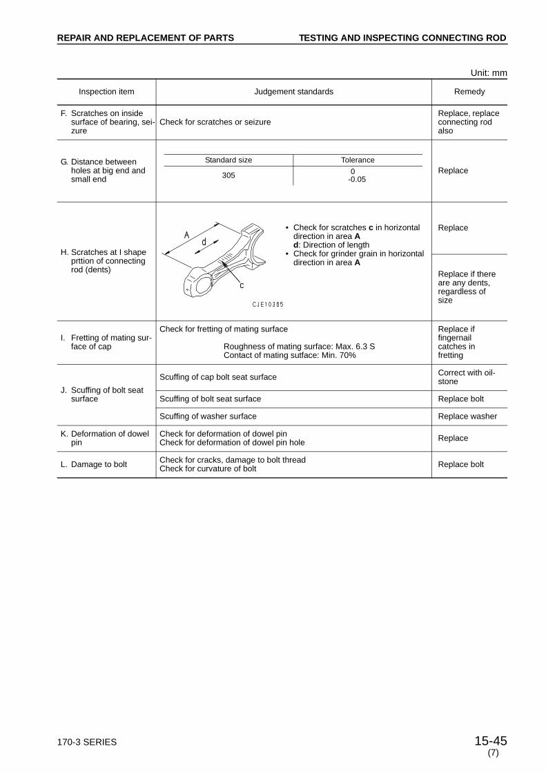
170-3 SERIES 15-45
REPAIR AND REPLACEMENT OF PARTS
Unit: mm
Inspection item Judgement standards Remedy
F. Scratches on inside surface of bearing, sei-zure
Check for scratches or seizureReplace, replace connecting rod also
G. Distance between holes at big end and small end
Replace
H. Scratches at I shape prttion of connecting rod (dents)
Replace
Replace if there are any dents, regardless of size
I. Fretting of mating sur-face of cap
Check for fretting of mating surface
Roughness of mating surface: Max. 6.3 SContact of mating sutface: Min. 70%
Replace if fingernail catches in fretting
J. Scuffing of bolt seat surface
Scuffing of cap bolt seat surface Correct with oil-stone
Scuffing of bolt seat surface Replace bolt
Scuffing of washer surface Replace washer
K. Deformation of dowel pin
Check for deformation of dowel pinCheck for deformation of dowel pin hole Replace
L. Damage to bolt Check for cracks, damage to bolt threadCheck for curvature of bolt Replace bolt
Standard size Tolerance
305 0-0.05
• Check for scratches c in horizontal direction in area Ad: Direction of length
• Check for grinder grain in horizontal direction in area A
(7)
TESTING AND INSPECTING CONNECTING ROD
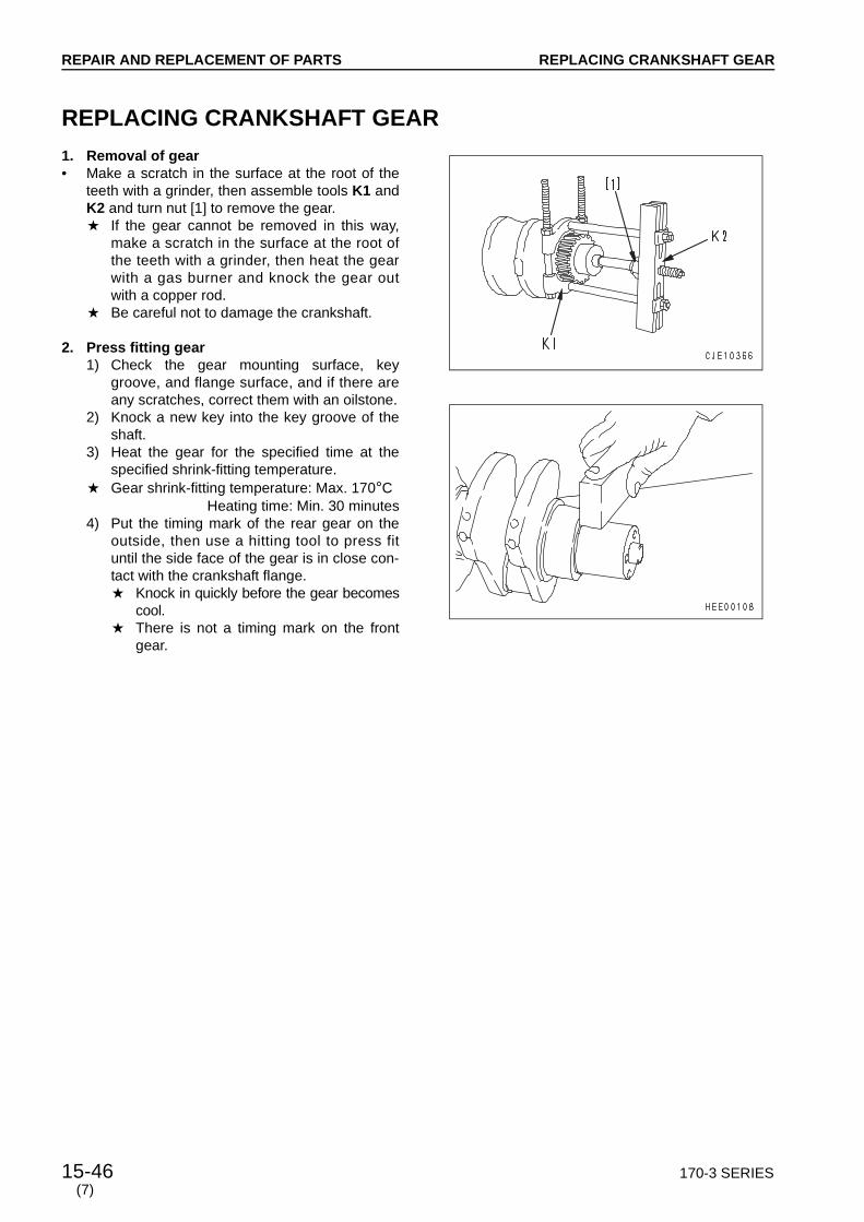
REPAIR AND REPLACEMENT OF PARTS
15-46 170-3 SERIES(7)
REPLACING CRANKSHAFT GEAR
1. Removal of gear• Make a scratch in the surface at the root of the
teeth with a grinder, then assemble tools K1 andK2 and turn nut [1] to remove the gear.a If the gear cannot be removed in this way,
make a scratch in the surface at the root ofthe teeth with a grinder, then heat the gearwith a gas burner and knock the gear outwith a copper rod.
a Be careful not to damage the crankshaft.
2. Press fitting gear1) Check the gear mounting surface, key
groove, and flange surface, and if there areany scratches, correct them with an oilstone.
2) Knock a new key into the key groove of theshaft.
3) Heat the gear for the specified time at thespecified shrink-fitting temperature.
a Gear shrink-fitting temperature: Max. 170°CHeating time: Min. 30 minutes
4) Put the timing mark of the rear gear on theoutside, then use a hitting tool to press fituntil the side face of the gear is in close con-tact with the crankshaft flange.a Knock in quickly before the gear becomes
cool.a There is not a timing mark on the front
gear.
REPLACING CRANKSHAFT GEAR
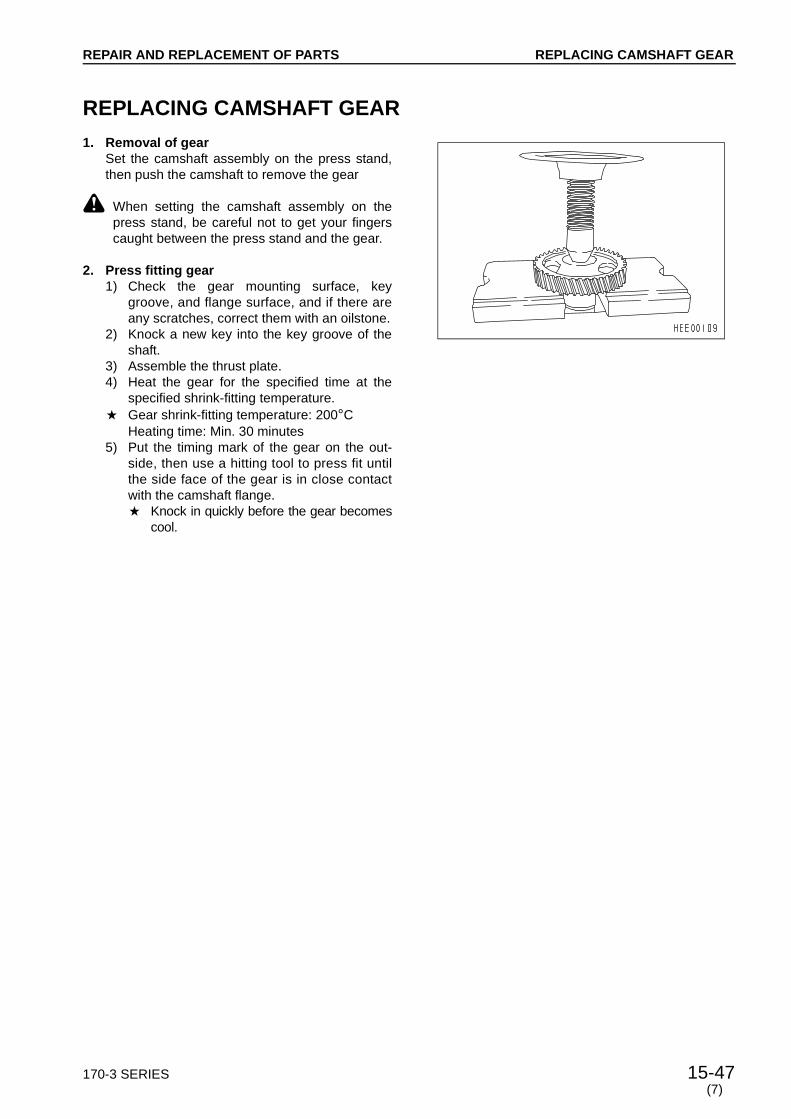
170-3 SERIES 15-47
REPAIR AND REPLACEMENT OF PARTS
REPLACING CAMSHAFT GEAR
1. Removal of gearSet the camshaft assembly on the press stand,then push the camshaft to remove the gear
k When setting the camshaft assembly on thepress stand, be careful not to get your fingerscaught between the press stand and the gear.
2. Press fitting gear1) Check the gear mounting surface, key
groove, and flange surface, and if there areany scratches, correct them with an oilstone.
2) Knock a new key into the key groove of theshaft.
3) Assemble the thrust plate.4) Heat the gear for the specified time at the
specified shrink-fitting temperature.a Gear shrink-fitting temperature: 200°C
Heating time: Min. 30 minutes5) Put the timing mark of the gear on the out-
side, then use a hitting tool to press fit untilthe side face of the gear is in close contactwith the camshaft flange.a Knock in quickly before the gear becomes
cool.
(7)
REPLACING CAMSHAFT GEAR

REPAIR AND REPLACEMENT OF PARTS
15-48 170-3 SERIES(7)
REPLACING FLYWHEEL RING GEAR
k Be careful not to let the flywheel fall and injureyou.
1. Removal of gear• Make a scratch in the surface at the root of the
gear teeth with a grinder, then split with a chiselto remove.
k Be careful when handling the grinder andchisel.
2. Press fitting gear1) Check the gear mounting surface, and if
there are any scratches, correct them with anoilstone.
2) Heat the gear for the specified time at thespecified shrink-fitting temperature.
a Gear shrink-fitting temperature: Max. 200°CHeating time: Min. 20 minutes
3) Set the chamfered face of the gear facing theflywheel, and press fit until the side face ofthe gear is in close contact with the flywheel.
REPLACING FLYWHEEL RING GEAR