manual profibus m310/b310 -...
TRANSCRIPT
Manual
Profibus M310/B310
Optional interface for Embedded-PCs CX9020, CX5xx0 andCX20x0
1.02016-06-06
Version:Date:


Table of contents
Profibus M310/B310 3Version: 1.0
Table of contents1 Foreword .................................................................................................................................................... 5
1.1 Notes on the documentation........................................................................................................... 51.2 Safety instructions .......................................................................................................................... 61.3 Documentation issue state ............................................................................................................. 7
2 PROFIBUS system overview .................................................................................................................... 82.1 Configuration options.................................................................................................................... 102.2 Communication protocols and services ........................................................................................ 132.3 Technical data - PROFIBUS......................................................................................................... 15
3 Connection and cabling.......................................................................................................................... 163.1 Profibus Connection ..................................................................................................................... 163.2 Cabling.......................................................................................................................................... 173.3 Topology ....................................................................................................................................... 20
4 TwinCAT tabs........................................................................................................................................... 214.1 Tree view ...................................................................................................................................... 214.2 Profibus master............................................................................................................................. 23
4.2.1 General ............................................................................................................................ 234.2.2 CCAT PBM....................................................................................................................... 244.2.3 Bus Parameters (DP) ....................................................................................................... 254.2.4 Startup/Fault settings ....................................................................................................... 264.2.5 ADS.................................................................................................................................. 274.2.6 DP diag ............................................................................................................................ 284.2.7 Box States........................................................................................................................ 29
4.3 Profibus slave ............................................................................................................................... 304.3.1 Profibus............................................................................................................................ 304.3.2 Features........................................................................................................................... 314.3.3 Diag.................................................................................................................................. 32
5 Parameterization and commissioning................................................................................................... 335.1 Synchronizing Profibus ................................................................................................................. 335.2 Parameterization with TwinCAT 2 ................................................................................................ 37
5.2.1 Searching for target systems ........................................................................................... 375.2.2 Adding a Profibus slave ................................................................................................... 395.2.3 Creating a virtual slave .................................................................................................... 415.2.4 Setting the address .......................................................................................................... 425.2.5 Creating a PLC project..................................................................................................... 435.2.6 Linking variables .............................................................................................................. 455.2.7 Load configuration to CX ................................................................................................. 465.2.8 Adding a Profibus master................................................................................................. 485.2.9 Testing Profibus networking............................................................................................. 495.2.10 'Turning' process data ...................................................................................................... 50
5.3 Parameterization with TwinCAT 3 ................................................................................................ 515.3.1 Searching for target systems ........................................................................................... 515.3.2 Adding a Profibus slave ................................................................................................... 535.3.3 Creating a virtual slave .................................................................................................... 555.3.4 Setting the address .......................................................................................................... 565.3.5 Creating a PLC project..................................................................................................... 575.3.6 Linking variables .............................................................................................................. 595.3.7 Load configuration to CX ................................................................................................. 605.3.8 Adding a Profibus master................................................................................................. 62
Table of contents
Profibus M310/B3104 Version: 1.0
5.3.9 Testing Profibus networking............................................................................................. 635.3.10 'Turning' process data ...................................................................................................... 64
6 Error handling and diagnostics ............................................................................................................. 656.1 Diagnostic LEDs ........................................................................................................................... 656.2 Error Reactions............................................................................................................................. 666.3 Master........................................................................................................................................... 69
6.3.1 ADS-Interface................................................................................................................... 706.3.2 DPV1 communication....................................................................................................... 736.3.3 Uploading the Configuration ............................................................................................ 74
6.4 Slave............................................................................................................................................. 756.4.1 Slave-Diagnose................................................................................................................ 776.4.2 Individual diagnostic data................................................................................................. 806.4.3 DP-V1 communication ..................................................................................................... 826.4.4 DP-V1 error codes ........................................................................................................... 84
7 Appendix .................................................................................................................................................. 857.1 Accessories .................................................................................................................................. 857.2 Certifications ................................................................................................................................. 867.3 Support and Service ..................................................................................................................... 87

Foreword
Profibus M310/B310 5Version: 1.0
1 Foreword
1.1 Notes on the documentationThis description is only intended for the use of trained specialists in control and automation engineering whoare familiar with the applicable national standards.It is essential that the documentation and the following notes and explanations are followed when installingand commissioning the components. It is the duty of the technical personnel to use the documentation published at the respective time of eachinstallation and commissioning.
The responsible staff must ensure that the application or use of the products described satisfy all therequirements for safety, including all the relevant laws, regulations, guidelines and standards.
Disclaimer
The documentation has been prepared with care. The products described are, however, constantly underdevelopment.We reserve the right to revise and change the documentation at any time and without prior announcement.No claims for the modification of products that have already been supplied may be made on the basis of thedata, diagrams and descriptions in this documentation.
Trademarks
Beckhoff®, TwinCAT®, EtherCAT®, Safety over EtherCAT®, TwinSAFE®, XFC® and XTS® are registeredtrademarks of and licensed by Beckhoff Automation GmbH.Other designations used in this publication may be trademarks whose use by third parties for their ownpurposes could violate the rights of the owners.
Patent Pending
The EtherCAT Technology is covered, including but not limited to the following patent applications andpatents:EP1590927, EP1789857, DE102004044764, DE102007017835with corresponding applications or registrations in various other countries.
The TwinCAT Technology is covered, including but not limited to the following patent applications andpatents:EP0851348, US6167425 with corresponding applications or registrations in various other countries.
EtherCAT® is registered trademark and patented technology, licensed by Beckhoff Automation GmbH,Germany
Copyright
© Beckhoff Automation GmbH & Co. KG, Germany.The reproduction, distribution and utilization of this document as well as the communication of its contents toothers without express authorization are prohibited.Offenders will be held liable for the payment of damages. All rights reserved in the event of the grant of apatent, utility model or design.
Foreword
Profibus M310/B3106 Version: 1.0
1.2 Safety instructionsSafety regulations
Please note the following safety instructions and explanations!Product-specific safety instructions can be found on following pages or in the areas mounting, wiring,commissioning etc.
Exclusion of liability
All the components are supplied in particular hardware and software configurations appropriate for theapplication. Modifications to hardware or software configurations other than those described in thedocumentation are not permitted, and nullify the liability of Beckhoff Automation GmbH & Co. KG.
Personnel qualification
This description is only intended for trained specialists in control, automation and drive engineering who arefamiliar with the applicable national standards.
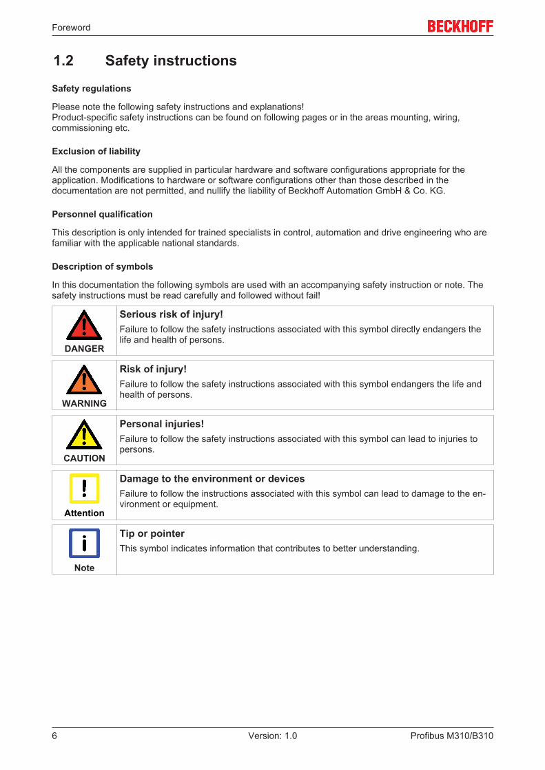
Description of symbols
In this documentation the following symbols are used with an accompanying safety instruction or note. Thesafety instructions must be read carefully and followed without fail!
DANGER
Serious risk of injury!Failure to follow the safety instructions associated with this symbol directly endangers thelife and health of persons.
WARNING
Risk of injury!Failure to follow the safety instructions associated with this symbol endangers the life andhealth of persons.
CAUTION
Personal injuries!Failure to follow the safety instructions associated with this symbol can lead to injuries topersons.
Attention
Damage to the environment or devicesFailure to follow the instructions associated with this symbol can lead to damage to the en-vironment or equipment.
Note
Tip or pointerThis symbol indicates information that contributes to better understanding.

Foreword
Profibus M310/B310 7Version: 1.0
1.3 Documentation issue stateVersion Modifications1.0 First version

PROFIBUS system overview
Profibus M310/B3108 Version: 1.0
2 PROFIBUS system overview
The Beckhoff Embedded PCs can be ordered ex works with an optional interface, e.g. PROFIBUS,CANopen or RS232. Some of the optional interfaces can be delivered as master or slave.
The following Embedded PCs can be ordered with an optional interface:
• CX9020• CX50x0• CX51x0• CX20x0
PROFIBUS master (M310)
The optional interface M310 is a PROFIBUS master and enables a segment-like construction of controlstructures in large plants and machines. Further Beckhoff fieldbus components such as Bus Couplers, BusTerminal Controllers, drive components, etc. can be used with an Embedded PC for configuring controlstructures.
Fieldbus masters are used for decentralized collection of process data and signals in large machines andplants. The number of slaves that can be connected to the master is only limited by the respective bussystem. Using master and slave connections makes it possible to link several Embedded PCs with eachother via the fieldbus level.
The optional interfaces are detected, parameterized and configured in TwinCAT, and the connected I/Ocomponents are added. TwinCAT is also used for diagnostics.
PROFIBUS slave (B310)
The optional interface B310 is a PROFIBUS slave and enables an Embedded PC to be used as subordinatedecentral controller for configuring complex or modular systems.
The PROFIBUS slave receives external process data from the master and processes them or returns datafrom its own process periphery to the master after processing.
Like the PROFIBUS master, the optional PROFIBUS slave interface is parameterized and configured inTwinCAT.
Functioning
PROFIBUS is a manufacturer - independent, open fieldbus standard with a wide range of applications inmanufacturing and process automation. Manufacturer-independence and openness are guaranteed by theInternational standards EN 50170 and EN 50254.
Further InformationPROFIBUS User Organization (PNO):www.profibus.com
PROFIBUS allows devices from different manufacturers to communicate without the need for speciallyadapted interfaces. PROFIBUS is suitable both for fast, time-critical applications and for complexcommunication tasks.

PROFIBUS system overview
Profibus M310/B310 9Version: 1.0
In PROFIBUS DP, central control devices (e.g. Industrial PCs or PLCs) communicate via a fast serialconnection with decentralized input and output modules. RS485 is the most frequently used transmissiontechnique, using a screened twisted pair cable. Data is mainly exchanged cyclically, although acyclicservices (DP-V1) are available for paramétrisation and diagnosis.
PROFIBUS DP offers short system response times: at a transmission rate of 12 Mbaud, less than 2 ms arerequired to transmit 512 bits each of input and output data to 32 devices.
All Beckhoff PROFIBUS devices feature a high-performance protocol implementation and are certified by thePROFIBUS user organization (PNO).
PROFIBUS distinguishes the following device types:
Master devices determine the data traffic on the bus. A master may transmit messages without havingreceived an external request when it is in possession of the bus access authorization (token). Masters arealso referred to as active devices.
Slave devices are peripheral devices such as input/output devices, valves, drives, measuring transducersand the Beckhoff PROFIBUS slaves from the BK3xx0, BC3xx0, IPxxxx-B310, IL230x-B310 and IL230x-C310series. They do not receive any bus access authorization, so that they are only allowed to acknowledgemessages that have been received, or to send messages in response to a request from master. Slaves arereferred to as passive devices. They only require a small proportion of the bus protocol, which means thatthey can be implemented with little effort.
PROFIBUS-DP
PROFIBUS DP is designed for efficient data exchange at the field level. The central automation devicessuch as PLC/PCs or process control systems communicate here over a fast serial link with decentralizedfield devices such as I/O, drives, valves, etc. Data is primarily exchanged with these distributed devicescyclically. The communication functions required for this are specified by the basic DP functions conforms toEN 50170.
Beyond these basic functions, PROFIBUS DP offers advanced acyclic communication services forparamétrisation and operation, for example, which are supported by Beckhoff PROFIBUS slaves ofthe IPxxxx-B310, IL230x-B310 and IL230x-C310 series. A central controller (master) cyclically reads theinput information from the slaves and cyclically writes the output information to the slaves. The bus cycletime here should be shorter than the central automation system's program cycle time, which lies around10 ms in many applications.

PROFIBUS system overview
Profibus M310/B31010 Version: 1.0
2.1 Configuration optionsPROFIBUS DP allows single master or multi-master systems to be implemented. This permits a high level offlexibility in system configuration. A maximum of 126 devices (master or slaves) can be connected to onebus. A station address between 0 and 99 can be chosen for the Beckhoff PROFIBUS slaves from theIPxxxx-B310, IL230x- B310 and IL230x-C310 series. The specifications for the system configuration containthe number of stations, the assignment of the station addresses to the I/O addresses, data consistency ofthe I/O data, the format of the diagnostics messages and the bus parameters being used. Every PROFIBUSDP system consists of different device types. Three types of device are distinguished:
Class DescriptionDP master class 1 (DPM1) This involves a central controller that exchanges information
cyclically with the decentral stations (slaves) in a specifiedmessage cycle. Typical devices include, for instance,programmable logic controllers (PLCs) or PCs.
DP master class 2 (DPM2) Devices of this type are engineering, project design or operatingdevices. They are used for commissioning, for servicing anddiagnosis in order to configure the connected devices, toevaluate measured values and parameters and to interrogate thestatus of devices.
DP slave A PROFIBUS DP slave is a peripheral device (I/O, drive,measuring transducer, etc.) that reads input information andpasses output information on to the peripherals. It is alsopossible to have devices that only handle either input or outputinformation. The quantity of input and output information isdevice-dependent, and may not exceed 240 bytes of input dataand 240 bytes of output data.
Mono master systems
In single master systems only one master is active on the bus in the operating phase of the bus system. ThePLC controller is the central control element. The decentralised slaves are coupled to the PLC controller viathe transmission medium. The shortest bus cycle time is achieved with this system configuration.
Basic device files (GSD)
In PROFIBUS DP, the performance characteristics of the devices are documented by the manufacturers andmade available to users in the form of a device data sheet and of a basic device file. The structure, contentand coding of these basic device files (GSD) is standardised. They make it easy to plan a project with anyPROFIBUS DP slaves using project planning devices from various manufacturers. The PROFIBUS UserOrganisation (Profibus Nutzer Organisation - PNO) archives this information for all manufacturers, and willprovide information about the GSD from any manufacturer on request. The GSD files are read by aPROFIBUS master configuration software, and appropriate adjustments are transferred to the PROFIBUSmaster. Please see the appropriate software manual from the master manufacturer for a description.
The Beckhoff GSD files may be obtained from the internet under http://www.beckhoff.de.
Diagnostic functions
The extensive diagnostic functions of PROFIBUS DP allow rapid fault localisation. Diagnosis of the BeckhoffBus Coupler is not activated in the default setting of the type file or the GSD file. The diagnostic messagesare transmitted over the bus and collated by the master.
They are divided into three levels:

PROFIBUS system overview
Profibus M310/B310 11Version: 1.0
Diagnosis type DescriptionStation-related Messages relating to the general operational readiness of a
device such as over-temperature or under-voltageModule-related These messages indicate that diagnostic signals are pending
within a specific I/O sub range of the device (e.g. an 8 bit outputmodule)
Channel-related Here the cause of an error is related to a single input/output bit(channel), such as a short circuit on output 2
The Beckhoff PROFIBUS slaves from the IPxxxx-B310, IL230x-B310 and IL230x-C310 series support thePROFIBUS DP diagnostic functions. Assessment of the diagnostic data by means of the controller dependson the support for the PROFIBUS master. Please refer to the device manuals for the master interfaces fordetails of how to handle the diagnosis.
Sync and Freeze Mode
In addition to the user data traffic related to the device, which is automatically dealt with by DPM1, a DPmaster has the option of sending control commands to one DP slave, to a group of them or to all of them atthe same time. These control commands are transmitted as multicasts. These control commands can beused to specify the sync and freeze operating modes, in order to synchronise the DP slave. They permitevent-controlled synchronisation of the DP slaves.
The DP slaves start sync mode when they receive a sync control command from the assigned DP master.In this operating mode, the outputs of all the addressed DP slaves are frozen at their current values. In thefollowing user data transmissions, the DP slaves store the output data, but the output states themselvesnevertheless remain unchanged. Only when the next sync control command is received from the master thestored output data is switched through to the outputs. Sync operation is ended with an unsync controlcommand.
A freeze control command similarly causes the addressed DP slaves to enter freeze mode. In this operatingmode the states of the inputs are frozen at their current value. The input data is only updated again when theDP master has sent the next freeze control command to the devices concerned. Freeze operation is endedwith an unfreeze command.
System behaviour
The system behaviour is also standardised in PROFIBUS DP, so that devices can to a large extent beinterchanged. It is largely determined by the operating state of the DPM1. This can either be controlledlocally, or over the bus by the project design device.
The following three major states are distinguished:
Operation mode DescriptionStop There is no data traffic between the DPM1 and the DP slaves.
The Bus Coupler only addresses the Bus Terminals once afterthe power has been switched on (none of the I/O LEDs are lit).
Clear The DPM1 reads the input information from the DP slaves, andmaintains the outputs of the DP slaves in a safe state (dependingon the reaction to fieldbus errors, the green I/O LED is lit and theoutputs are set).
Operate The DPM1 is in a data transfer phase. In the course of cyclic datatraffic the inputs of the DP slaves are read and the outputinformation is transmitted to the DP slaves (the green I/O LED islit).
The DPM1 sends its local status at a configurable time interval using a multicast command cyclically to allthe DP slaves that have been assigned to it. The reaction that the system has to the occurrence of an errorduring the DPM1's data transfer phase, such as the failure of a DP slave, is specified in the Auto-Clearoperating parameter. If this parameter is set to True, then the DPM1 switches the outputs of all the

PROFIBUS system overview
Profibus M310/B31012 Version: 1.0
associated DP slaves into a safe state as soon as one DP slave is no longer ready for the transfer of userdata. The DPM1 then switches into the Clear state. If the parameter is False then the DPM1 remains in theoperating state even after a fault, and the user can himself specify the system's reaction.
Data traffic between the DPM1 and the DP slaves
The data traffic between the DPM1 and the DP slaves that have been assigned to it is automaticallyexecuted by the DPM1 in a specified, continuously repeated sequence. The user specifies the assignment ofa DP slave to the DPM1 when the bus system's project is being planned. Those DP slaves that are includedin or excluded from the cyclic user data traffic are also defined.
The data traffic between the DPM1 and the DP slaves is divided into the paramétrisation, configuration anddata transfer phases.
Before a DP slave is included in the data transfer phase, the DPM1 checks, in the paramétrisation andconfiguration phase, whether the theoretical configuration that has been planned agrees with the actualconfiguration of devices. The check requires the device type, the format and length information, as well asthe number of inputs and outputs, to be in agreement. The user is thus provided with reliable protectionagainst errors in paramétrisation. In addition to the transfer of user data, which is automatically carried out bythe DPM1, it is possible to send new paramétrisation data to the DP slaves at the user's request.
Protection mechanisms
In the context of decentralised peripherals it is necessary, for reasons of safety and reliability, for the systemto be given extremely effective functions to protect against incorrect paramétrisation or the failure of thetransmission mechanisms. PROFIBUS DP uses monitoring mechanisms in the DP Master and in the DPSlaves. They are implemented in the form of time monitors. The monitoring interval is specified in when theDP system project is planned.
Protection mechanisms DescriptionAt the DP Master The DPM1 monitors the slave's transfer of user data with the
Data_Control_Timer. An individual monitoring timer is used foreach assigned slave. The time monitor triggers if a propertransfer of user data does not take place within the monitoringinterval. In this case the user is informed. If automatic errorreaction is enabled (Auto_Clear = True) then the DPM1 leavesthe Operate state, switches the outputs of the assigned slavesinto a safe state, and then goes into the Clear operating mode.
At the DP Slave The slave uses communication monitoring in order to detecterrors of the master or in the transmission segment. If data is nottransferred with the assigned master within the communicationmonitoring interval the slave switches the outputs into the safestate itself. The slave inputs and outputs further require accessprotection in multi-master systems, to ensure that direct access isonly made from the authorized master. The slaves will make animage of the inputs and outputs available to other masters, andthis can be read by any other master even if it does not haveaccess authorization.
Ident number
Every DP slave and every DPM1 must have an individual identification number. This is required so that a DPmaster can identify the types of the connected devices without any significant protocol overhead. The mastercompares the identification numbers of the connected DP devices with the identification numbers in theproject planning data specified by DPM2. The transfer of user data only starts if the correct device types areconnected to the bus at the correct station addresses. This provides protection from project planning errors.Manufacturer-specific identification numbers are issued by the PROFIBUS User Organisation (PNO). ThePNO administers the identification numbers along with the basic device data (GSD).

PROFIBUS system overview
Profibus M310/B310 13Version: 1.0
2.2 Communication protocols and servicesIn PROFIBUS DP systems a master (PLC, PC, etc.) usually communicates with many slaves (I/Os, drives,etc.); only the master actively accesses the bus (by sending unsolicited telegrams), while a DP slave onlysends telegrams when requested by the master.
PROFIBUS DP• DP-StartUp
Before the master and the slave exchange data cyclically, parameter and configuration data aretransferred from the master to the slaves during the DP startup. Once the parameter and configurationdata have been sent, the master queries the diagnostic data of the slave until the slave indicates itsreadiness for data exchange. This process can take several seconds, depending on the scope of thecalculations, which the slave has to carry out based on the parameter and configuration data it hasreceived.
• Parameter dataThe master sends the parameter data to the slaves with the SetPrmLock request telegram. TheSetPrmLock response telegram contains no data and only consists of one byte, which represents ashort acknowledgement. The parameter data consist of DP parameters (e.g. the DP watchdog and theID number), the DPV1/DPV2 parameters and application-specific parameters, which only have to betransferred once during startup. If an error is found in the parameter data, this is indicated in thediagnostic data, and the slave either remains in or enters the WAIT-PRM state.
• Configuration dataThe master sends the configuration data to the slaves with the ChkCfg request telegram. The ChkCfgresponse telegram contains no data and only consists of one byte, which represents a shortacknowledgement. The configuration data describes the assignment of the DP modules to the cyclic I/O data that is to be exchanged between the master and slave via the Data_Exchange telegram in thecyclic data exchange phase. The order of the DP modules attached to a slave determines the order ofthe corresponding I/O data in the data exchange telegram.
• Diagnostic dataThe master requests the diagnostic data with a SlaveDiag request telegram. The slave sends thediagnostic data with a SlaveDiag response telegram. The diagnostic data consist of the standard DPdiagnostic data (e.g. state of the slave, ID number) and application-specific diagnostic data.
• Cyclic data exchangeAt the core of the PROFIBUS DP protocol is the cyclic data exchange, during which the masterexchanges I/O data with each slave within a PROFIBUS DP cycle. The master sends the outputs toeach slave with a DataExchange request telegram. The slave returns the inputs in a DataExchangeresponse telegram. This means that all the output and/or input data is transmitted in one telegram, inwhich the DP configuration (the sequence of DP modules) specifies the assignment of the output and/or input data to the slave's actual process data.
• Diagnosis during cyclic data exchangeA slave can send a diagnostics signal to the master during cyclic data exchange. In this case, the slavesets a flag in the DataExchange response telegram, whereby the master recognizes that there is newdiagnostic data at the slave. The master then fetches these data with a SlaveDiag telegram. Thediagnostic data is therefore not available at the same time as the cyclic I/O data, but always delayed byat least one DP cycle.
• Synchronisation with Sync and FreezeThe Sync and Freeze commands in the GlobalControl request telegram allow the master tosynchronise the activation of the outputs (Sync) or the reading of the inputs (Freeze) in a number ofslaves.If sync commands are used, the slaves are initially switched to sync mode (this is acknowledged in thediagnostic data). The I/O data are then exchanged sequentially exchanged with the slaves viaDataExchange telegrams. When the sync command is sent in the GlobalControl telegram, the slavesissue the last received outputs. In Freeze operation a Freeze command is first sent in theGlobalControl telegram, in response to which all the slaves latch their inputs. These are then fetchedsequentially by the master in the DataExchange telegram.
• States in the masterThe master distinguishes between the CLEAR state (all outputs are set to the Fail_Safe value) and theOPERATE state (all outputs have the process value). The Master is usually switched into the CLEARmode when, for instance, the PLC enters STOP.

PROFIBUS system overview
Profibus M310/B31014 Version: 1.0
• Class 1 and Class 2 DP MastersThe Class 1 master refers to the controller that carries out cyclic I/O data exchange with the slaves,while a Class 2 master is a B&B device that generally only has read access to the slaves' I/O data.
PROFIBUS DPV1
PROFIBUS DPV1 refers primarily to the acyclic read and write telegrams, with which data sets in the slaveare acyclically accessed. A distinction between a Class 1 and a Class 2 master is also made for DPV1.
• Class 1 (C1)The acyclic C1 connection is established with the DP startup during cyclic DP operation. Acyclic DPV1C1 read and write telegrams can be sent from the master to the slave from the state WAIT-CFG of theslave.
• Class 2 (C2)In the case of C2, a second C2 master usually establishes a separate connection, independent of thecyclic DP connection, so that a manufacturer-specific project planning and diagnostic tool can accessthe slave data, for example.If two masters are used, please note that they share the bus access, and the temporal conditions aretherefore less favorable compared with a single master.

PROFIBUS system overview
Profibus M310/B310 15Version: 1.0
2.3 Technical data - PROFIBUSOptional interface M310
Technical data M310Fieldbus PROFIBUS DP, DP-V1; DP-V2 (MC)Data transfer rate 9,6k; 19,2k; 93,75k; 187,5k; 500k; 1,5M; 3M; 6M; 12
MBaudBus interface 1 x D sub-socket, 9-pinBus devices max. 125 with repeatermax. process image 30.5 kbytes in / 30.5 kbytes outProperties PROFIBUS – different DP cycle times possible for
each slave; error management for each device freelyconfigurable
Optional interface B310
Technical data B310Fieldbus PROFIBUS DP, DP-V1Data transfer rate 9,6k; 19,2k; 93,75k; 187,5k; 500k; 1,5M; 3M; 6M; 12
MBaudBus interface 1 x D sub-socket, 9-pinExtendable process image Up to 15 virtual slaves in additionmax. process image 16 slaves x (240 bytes in / 240 bytes out)

Connection and cabling
Profibus M310/B31016 Version: 1.0
3 Connection and cabling
3.1 Profibus ConnectionNine-pin D sub
Pin 6 transfers 5 VDC, pin 5 transfers GND for the active termination resistor. These must never be used forother functions, as this can lead to destruction of the device.
Pins 3 and 8 transfer the PROFIBUS signals. These must never be swapped over, as this will preventcommunication.
The Profibus bus line is connected via a 9-pin D sub with the following pin assignment:
Pin Assignment1 Shielding2 not used3 RxD/TxD-P4 not used5 GND6 +5VDC
7 not used8 RxD/TxD-N9 not used
cable colors
PROFIBUS line D subB red Pin 3A green Pin 8

Connection and cabling
Profibus M310/B310 17Version: 1.0
3.2 CablingPhysical aspects of the data transmission are defined in the PROFIBUS standard (see PROFIBUS layer 1:Physical Layer).
The types of area where a fieldbus system can be used is largely determined by the choice of thetransmission medium and the physical bus interface. In addition to the requirements for transmissionsecurity, the expense and work involved in acquiring and installing the bus cable is of crucial significance.The PROFIBUS standard therefore allows for a variety of implementations of the transmission technologywhile retaining a uniform bus protocol.
Cable-based transmission:
This version, which accords with the American EIA RS-485 standard, was specified as a basic version forapplications in production engineering, building management and drive technology. A twisted copper cablewith one pair of conductors is used. Depending on the intended application area (EMC aspects should beconsidered) the screening may be omitted.
Two types of conductor are available, with differing maximum conductor lengths (see the RS485 table).
RS-485 transmission according to the PROFIBUS standardNetwork topology Linear bus, active bus terminator at both ends, stubs
are possible.Medium Screened twisted cable, screening may be omitted,
depending upon the environmental conditions (EMC).Number of stations 32 stations in each segment with no repeater. Can be
extended to 125 stations with repeaterMax. bus length without repeater 100 m at 12 Mbit/s
200 m at 1500 Kbit/s, up to 1.2 km at 93.75 kbit/sMax. bus length with repeater Line amplifiers, or repeaters, can increase the bus
length up to 10 km. The number of repeaters possibleis at least 3, and, depending on the manufacturer,may be up to 10.
Transmission speed (adjustable in steps) 9.6 kbit/s; 19.2 kbit/s; 93.75 kbit/s; 187.5 kbit/s; 500kbit/s; 1500 kbit/s; 12 Mbit/s
Connector 9-pin D sub connector for IP20M12 round connector for IP65/67
Cable-related malfunctions
Note the special requirements on the data cable for baud rates greater than 1.5 Mbaud. The correct cable isa basic requirement for correct operation of the bus system. If a simple 1.5 Mbaud cable is used, reflectionsand excessive attenuation can lead to some surprising phenomena. It is possible, for instance, for aconnected PROFIBUS station not to achieve a connection, but for it to be included again when theneighboring station is disconnected. Or there may be transmission errors when a specific bit pattern istransmitted. The result of this can be that when the equipment is not operating, PROFIBUS works withoutfaults, but that there are apparently random bus errors after start-up. Reducing the baud rate (< 93.75 kbaud)corrects this faulty behaviour.
If reducing the baud rate does not correct the error, then in many cases this can indicate a wiring fault. Thetwo data lines may be crossed over at one or more connectors, or the termination resistors may not beactive, or they may be active at the wrong locations.
Note
Pre-assembled cable from BECKHOFFInstallation is made a great deal more straightforward if pre-assembled cables from BECK-HOFF are used! Wiring errors are avoided, and commissioning is more rapidly completed.The BECKHOFF range includes fieldbus cables, power supply cables, sensor cables andaccessories such as terminating resistors and T-pieces. Connectors and cables for field as-sembly are nevertheless also available.

Connection and cabling
Profibus M310/B31018 Version: 1.0
The following diagram shows the cabling between two stations, as well as the D sub connection assignment:
Note
Termination resistorsIn systems with more than two stations all devices are wired in parallel. It is essential thatthe bus cables are terminated with resistors at the conductor ends in order to avoid reflec-tions and associated transmission problems.
Distances
The bus cable is specified in EN 50170. This yields the following lengths for a bus segment.
Baud ratein kbits/sec
9.6 19.2 93.75 187.5 500 1500 12000
Cablelength in m
1200 1200 1200 1000 400 200 100
Stubs up to 1500 kbaud <6.6 m; at 12 Mbaud stub segments should not be used.
Bus segments
A bus segment consists of at most 32 devices. 125 devices are permitted in a PROFIBUS network.Repeaters are required to refresh the signal in order to achieve this number. Each repeater is counted asone device.
IP-Link is the subsidiary bus system for Fieldbus Boxes, whose topology is a ring structure. There is an IP-Link master in the coupler modules (IP230x-Bxxx or IP230x-Cxxx) to which up to 120 extension modules(IExxxx) may be connected. The distance between two modules may not exceed 5 m. When planning andinstalling the modules, remember that because of the ring structure the IP-Link master must be connectedagain to the last module.
Installation guidelines
When assembling the modules and laying the cables, observe the technical guidelines provided by thePROFIBUS User Organisation (PROFIBUS Nutzerorganisation e.V.) for PROFIBUS DP/FMS (see:www.profibus.de).
Check the PROFIBUS cable
A PROFIBUS cable (or a cable segment when using repeaters) can be checked with a few simple resistancemeasurements. The cable should meanwhile be removed from all stations:
1. Resistance between A and B at the start of the lead: approx. 110 Ohm2. Resistance between A and B at the end of the lead: approx. 110 Ohm3. Resistance between A at the start and A at the end of the lead: approx. 0 Ohm4. Resistance between B at the start and B at the end of the lead: approx. 0 Ohm5. Resistance between screen at the start and screen at the end of the lead: approx. 0 Ohm

Connection and cabling
Profibus M310/B310 19Version: 1.0
If these measurements are successful, the cable is okay. If, in spite of this, bus malfunctions still occur, thisis usually a result of EMC interference. Observe the installation notes from the PROFIBUS UserOrganisation (www.profibus.com).

Connection and cabling
Profibus M310/B31020 Version: 1.0
3.3 Topology• A bus segment may consist of a maximum of 32 devices (including the repeaters).• The maximum conductor length of a segment depends on the transmission speed in use and on the
quality of the bus cables being used.• No more than 9 repeaters may be installed between two devices.• Stubs are to be avoided, and are not permitted above 1.5 Mbaud.• The maximum number of devices is 125• Interrupting the supply voltages from cable ends by switching off the repeater/slave, or by pulling out
the plug, is not permitted.

TwinCAT tabs
Profibus M310/B310 21Version: 1.0
4 TwinCAT tabsIn TwinCAT, information and settings for the Profibus interface are added under tabs. The main TwinCATtabs are described in this section. In addition, the section illustrates how the Profibus interface is displayed inthe tree view under TwinCAT.
The tree view and the tabs for a Profibus interface are identical under TwinCAT2 and TwinCAT3.
4.1 Tree viewA Profibus master and a Profibus slave are displayed as follows in the tree view:
1
2
3
4
In this example the slave was linked to the master. TwinCAT was then scanned for the master, and themaster was added in TwinCAT together with the slave.
Number Description1 The device name of the master is shown in brackets. All Profibus slaves are added under
the master.2 Under the Profibus master, status messages are listed as input variables and output
variables. The variables can be linked with the PLC and used for diagnostic purposes (e.g.error codes, counters, etc.).
3 Profibus slaves are added under the master, labelled as box and numbered consecutively.The device name appears in brackets after it.Each Profibus slave has its own input variables for diagnostic purposes, which indicate thestate of the communication (DPState, ExtDiagFlag).
4 Further settings for the Profibus master or slave can be implemented under the tabs.Other tabs are displayed, depending on whether the master or slave is selected in the treeview.
A Profibus slave and the corresponding tabs are shown as follows in the tree view:

TwinCAT tabs
Profibus M310/B31022 Version: 1.0
1
2
3
Number Description1 Under the Profibus slave, status messages are listed as input variables. The variables can
be linked with the PLC and used for diagnostic purposes. The inputs DpState andExtDiagFlag are created for each slave box. In addition, process data for the data exchangeare added under the slave.
2 All slaves are added under the master. This example shows the B3100 with connected BusTerminals. All available terminals are displayed with their inputs and outputs.
3 Further settings for the Profibus slave can be implemented under the tabs.Other tabs are displayed, depending on whether the master or slave is selected in the treeview.
When the PLC process image is read, the variables for status messages and the variables under theprocess data can be linked with the variables from the PLC program. Double-click on a variable name in thetree view to open the link dialog. The link variables are identified with a small arrow icon.
Further information about TwinCAT can be found in the TwinCAT documentation on the Beckhoff website:www.beckhoff.de

TwinCAT tabs
Profibus M310/B310 23Version: 1.0
4.2 Profibus master
4.2.1 GeneralThe General tab contains general information for a Profibus device, including name, type and ID.
1
3
4
2
5
No. Description1 Name of the Profibus device2 Type of the Profibus device3 Here you can add a comment (e.g. notes relating to the system component)4 Here you can disable the Profibus device5 Running No.
The Profibus device can be switched off via this tab. A comment field offers the option to add a label, in orderto provide additional information on the device.

TwinCAT tabs
Profibus M310/B31024 Version: 1.0
4.2.2 CCAT PBM
1
5
9
11
3
4
2
10
6
7
8
12
13
No. Description1 Name of the physical interface.
Name and type of the Profibus device.2 Unique station no. of the master.3 The baud rate is set here.4 Use this button to open the Bus Parameters window (see: Bus Parameters
(DP) [} 25]).5 Here you can select from the following three operating modes: DP, DP
(equidistant/no GC) and DP/MC (equidistant). In all three operating modesthe task with the highest priority linked to the corresponding device controlsthe PROFIBUS cycle and is therefore synchronized with the DP cycle.
6 Displays the cycle time of the corresponding highest priority task.7 The expected Profibus cycle time is displayed here.8 This button is used to open the Startup/Fault Settings window (see: Startup/
Fault settings [} 26])9 Here the Profibus is scanned and compared with the currently added boxes.
Any deviations are displayed.10 Here the PROFIBUS is scanned, and all devices that are found are added
to the master. For Beckhoff boxes the configuration is read exactly, forexternal devices the system searches for the corresponding device masterfile.
11 Shows the current firmware version.12 Shows the current version of the CCAT drivers.13 The Search button is used to find and select the required physical interface,
if not done automatically already.

TwinCAT tabs
Profibus M310/B310 25Version: 1.0
4.2.3 Bus Parameters (DP)
1
5
8
3
4
2
7
6
No. Description1 The Slot Time indicates how long the DP master will wait for a response
from the DP slave before it sends either a repetition or the next telegram.2 The minimum Tsdr indicates the minimum length of time for which the DP
slave will wait with a response. This time is set for all the DP slaves duringthe DP start-up (the value range is 11-255 bit periods). The minimum Tsdrmust be smaller than the maximum Tsdr.
3 The maximum Tsdr indicates the maximum length of time for which the DPslave may wait with a response. This time is set according to the DP slave'sGSD file entries. The maximum Tsdr must be smaller than the slot time.
4 The Max Retry limit indicates how often a telegram is resent, if theaddressed device does not respond. A value of at least 1 should be set, toensure that for acyclic telegrams the telegram is repeated at least once inthe event of an error.
5 Since the Data_Exchange telegram is repeated cyclically, a value of 0 couldbe used for the repetition of the Data_Exchange telegram here, in order tokeep the cycle relatively constant in equidistant mode, even if there is noresponse from a device.However, in this case it would make sense to set the Features tab for thebox such that lack of response of the slave would not lead to DATA EXCHbeing exited (see: Features [} 31]). If a device has not responded, this isindicated by the DpState, which in this case is not 0 for one cycle.
6 A distinction can be made between master functionality (default) and multi-slave.
7 This button is used to optimize the bus parameters.8 This button is used to set the standard bus parameters.

TwinCAT tabs
Profibus M310/B31026 Version: 1.0
4.2.4 Startup/Fault settings
1
2
4
3
No. Description1 The DP master changes automatically into the clear mode (the outputs of
the slaves are set either to 0 or to the fail-safe value) when it ceases toreceive an interrupt from the associated task (e.g. a PLC breakpoint hasbeen reached, or the system has crashed). Here you can specify how manymissing task cycles are tolerated before the master switches to Clear mode.
2 This button is used to set the DP watchdog for all DP slaves to an optimumvalue.
3 If the checkbox Set WD individually for each Slave is not ticked, the DPwatchdog can be set to a uniform value for all slaves.
4 Here you can select whether the watchdog is to be set individually for eachslave. If the checkbox is ticked, the watchdog can be set for each slave onthe Profibus tab (see: Profibus [} 30]).

TwinCAT tabs
Profibus M310/B310 27Version: 1.0
4.2.5 ADS
The Profibus master is an ADS device with its own Net ID, which can be modified here. All ADS services(diagnostics, acyclic communication) sent to the Profibus master must use this Net ID and port no.

TwinCAT tabs
Profibus M310/B31028 Version: 1.0
4.2.6 DP diagAny problems with the cabling and the DP cycle times are displayed here.
1
5
3
2
4
6
No. Description1 detected bus errors:
Displays the number of bus errors detected. If this counter is not 0, thecabling should be checked, if no PROFIBUS plug connectors wereunplugged or connected. Unplugging of PROFIBUS connectors usuallyresults in brief bus interference.
2 CycleWithRepeatCounter:Here, the number of PROFIBUS cycles is displayed, in which a telegramwas repeated at least once. Repetitions indicate that there is somethingwrong with the bus hardware.Max. Repeat/Cycle:Here, the maximum number of repetitions within a cycle is displayed.
3 Measured Cycle Times:Displays the measured cycle times.
4 Failed-Cycle-Counter:The counter increments if the DP cycle was not complete before the nexttask cycle was started and all slaves are in data exchange (i.e. they have aDpState of 0).
5 CycleWithNoDxch-Counter:Increments if not all slaves exchange data (i.e. DpState is not 0).
6 max./min./actual Cycle-Time:Displays the maximum, minimum and current DP cycle times; only thosecycles are taken into account, in which all slaves have exchanged data andno repetitions have occurred.

TwinCAT tabs
Profibus M310/B310 29Version: 1.0
4.2.7 Box States
The connected Profibus slaves are listed in the Box States tab. This overview can be used to detect errorssuch as connection problems at the boxes.

TwinCAT tabs
Profibus M310/B31030 Version: 1.0
4.3 Profibus slave
4.3.1 Profibus
1
5
7
3
4
2
6
No. Description1 The hardware address set on the slave is entered here. There are slaves,
for which the address cannot be set on the hardware, but only via theSetSlaveAddress service.In this case use the Set button to start a dialog for sending aSetSlaveAdress telegram and setting an address.
2 The current configuration data (resulting from the attached modules orterminals) as well as their length is displayed.
3 Enables editing of Profibus-specific parameter data. The size of the currentparameter data is also displayed. The PrmData can usually be set as text (-> PrmData (text)) or for Beckhoff DP slaves partly via the “Beckhoff” tab.
4 Watchdog:Activates the DP watchdog. If the slave does not receive a DP telegram forthe duration of the watchdog time with the watchdog switched on, it willautomatically exit the data exchange. The minimum watchdog time dependson the DP cycle time and should be greater than the value calculated basedon the following formula: Estimated-Cycle-Time * 10.For particularly critical outputs a DP watchdog of up to 2 ms can be set canfor DP slaves, which support a watchdog base time of 1 ms. The DPwatchdog time should be at least twice the maximum of cycle time andestimated cycle time (see: CCAT PBM [} 24]).
5 With this button, provided TwinCAT has been started, cyclic data exchangewith the DP slave can be disabled and re-established immediately(corresponds to an IO reset but only for the one slave).
6 In operating mode DP/MC (equidistant) of the master, slaves can beoperated with Sync and Freeze.
7 Here, the Ident number from the GSD file is displayed.

TwinCAT tabs
Profibus M310/B310 31Version: 1.0
4.3.2 Features
3
4
2
1
No. Description1 Here you can set whether the slave should continue to send data (Stay in
Data Exch), even if it does not respond or respond erratically. In this casethe data exchange remains active until the slave fails to respond correctlywithin the watchdog time (watchdog function is enabled, see Profibus tab ofthe slave). Otherwise the data exchange is not interrupted until the slavehas responded incorrectly 65535 times.
2 Here you can specify whether the slave should restart automatically orremain in WaitPrm state, once it has exited the data exchange.
3 For each slave you can specify whether exit from Data Exch should lead toa stop of the PROFIBUS cycle (all slaves exit the data exchange and enterthe WaitPrm state. A restart is only possible through an IO reset or restart ofthe TwinCAT system).
4 For each slave it can be specified whether, on exiting of Data Exch(DpState not equal 0), its input data should be set to 0 or remainunchanged.

TwinCAT tabs
Profibus M310/B31032 Version: 1.0
4.3.3 Diag
This tab offers an overview of the slave state and the Profibus connection. Here the diagnostic data of thepreceding tabs can be displayed in consolidated form. The following and further important information can beviewed here:
BoxState: The current DpState is displayed here.
Receive-Error-Counter: Number of disturbed telegrams from the slave.
Repeat-Counter: Number of required repetitions due to missing or disturbed response from the slave.
NoAnswer-Counter: Number of telegrams that remained unanswered by the slave.
Last DPV1 error: Error-Decode, Error-Class, Error-Code and Error-Code 2 (see description of the DPV1Error Codes).

Parameterization and commissioning
Profibus M310/B310 33Version: 1.0
5 Parameterization and commissioningThis documentation uses Profibus devices to illustrate the commissioning procedure. The configurationoptions shown in this section can be used for all Embedded PCs with Profibus interface.
The following devices are used in this documentation:
• CX2020-M310 (Embedded PC with optional Profibus master interface, D-sub socket, 9-pin)• CX2500-B310 (Embedded PC with fieldbus module CX2500-B310 Profibus slave, D-sub socket, 9-pin)• BK3100 (Profibus slave, D-sub socket, 9-pin)
The TwinCAT 2 or TwinCAT 3 software is used for configuring the devices.
For further information see the TwinCAT 2 and TwinCAT 3 documentation, which is available from theBeckhoff website:www.beckhoff.de
5.1 Synchronizing ProfibusIn TwinCAT Run mode the Profibus master is always synchronized with the highest priority task, with whichvariables are linked. Once the mapping was created, the cycle time of the corresponding task is displayedunder Cycle Time on the CCAT PBM tab of the master. It is possible to set for the task whether the "I/O attask begin" should be updated or not.
Prerequisites for this step:
• A task created in TwinCAT, with which variables from the PLC project are linked.
The option "I/O at task begin" can be activated as follows:1. Click on the corresponding task in the tree view on the left.
2. Click on the Task tab, then select the option "I/O at task begin".
ð You have successfully activated the option "I/O at task begin". The following section explains the effect ofthis setting on the task time and the DP cycle.
I/O at Task Start
If the setting I/O at task begin is activated (default for NC task), before the task starts the system checkswhether the previous DP cycle was completed. The inputs and outputs are then copied (the outputs from thelast task cycle are used), and the DP cycle is started.
Sample: Task cycle time 2 ms, real-time resources 80%.

Parameterization and commissioning
Profibus M310/B31034 Version: 1.0
If copying of the inputs and outputs and the task computing time of 0.8 ms is exceeded, task execution isinterrupted, since the 80% real-time resources limit is reached:
This case would still not be a problem, because the DP cycle was completed within the available time.
If the setting I/O at task begin is not activated, the sequence is somewhat more critical. The next exampleshows the effects.
I/O not at Task Start
If the setting I/O at task begin is not selected for the task (default for PLC task), before the task starts thesystem checks whether the previous DP cycle was completed, and the inputs are copied. Task processingthen commences. At the end of the task the outputs are copied, and the DP cycle is started.
Sample: Task cycle time 2 ms, real-time resources 80%.
Since in this case the task and the PROFIBUS have to share the bandwidth, exceedance of the real-timeresources has a stronger effect than in the case "I/O at task begin":

Parameterization and commissioning
Profibus M310/B310 35Version: 1.0
The DP cycle starts later and is not completed in time before the next cycle. The system detects that the lastDP cycle could not be completed. No inputs are copied before the start of the next task (the task uses the oldinputs), and no outputs are copied after the task has been processed. The DP cycle is not restarted, whichmean that a DP cycle is omitted.
The variable CycleCounter is used to indicate an omitted DP cycle (see: Master [} 69] diagnostics).
Comparison of I/O at task start and I/O not at task start
The advantage of the I/O at task begin setting is that the task and the DP cycle do not have to share theavailable bandwidth. The DP cycle starts very constant (the jitter corresponds to the TwinCAT jitter). If thesetting I/O at task begin is not activated, it can easily happen that a DP cycle is omitted, and the temporalconstancy of the DP cycle additionally depends on the jitter of the task processing.
The disadvantage of the I/O at task begin setting is that the dead time, i.e. the system reaction time,increases.
Sync/Freeze functionality
Sync is used for the simultaneous outputting of outputs for several slaves, Freeze is used for reading ininputs from several slaves simultaneously.
The TwinCAT process is as follows:
• The outputs are written at the beginning (I/O at the start of the task) or the end (I/O not at the start ofthe task) of the task cycle
• This will start the PROFIBUS cycle• A Sync/Freeze telegram is sent at the start of the PROFIBUS cycle• This will cause the Bus Couplers to start a K-Bus cycle with the outputs from the last task cycle and
transfer the inputs from the last K-Bus cycle• The master will then send the current outputs to each slave and pick up the transferred inputs• The inputs are read at the start of the next task cycle• etc.
Outputs and inputs are therefore always one cycle old.
For a master that is to be operated in Sync/Freeze mode, the option DP/MC (Equidistant) must be set in theCCAT PBM tab under Operation Mode (see: CCAT PBM [} 24]).

Parameterization and commissioning
Profibus M310/B31036 Version: 1.0
For a slave that is to be operated in Sync/Freeze mode, the option Sync/Freeze enable must be selected onthe Profibus tab (see: Profibus [} 30]). The master always uses group 1 for the Sync/Freezesynchronization.

Parameterization and commissioning
Profibus M310/B310 37Version: 1.0
5.2 Parameterization with TwinCAT 2This section illustrates how Profibus devices can be parameterized with the aid of TwinCAT 2. A total ofthree devices are used for the example, including a Profibus master, to which two Profibus slaves areconnected.
First, the process of finding and selecting a target system in TwinCAT is illustrated. Next, a Profibus slave isadded and parameterized in TwinCAT, and the Profibus address of the slave is set. Then a PLC project iscreated and added in TwinCAT. Then, the variables from the PLC project are linked with the hardware, andthe finished configuration is loaded on the Profibus slave.
In the last step, the Profibus master is added in TwinCAT, and the two Profibus slaves are located via themaster. The process of testing the Profibus networking is then illustrated.
5.2.1 Searching for target systemsBefore you can work with the devices, you must connect your local computer to the target device. Then youcan search for the devices with the help of the IP address or the host name.
The local PC and the target devices must be connected to the same network or directly to each other via anEthernet cable. In TwinCAT a search can be performed for all devices in this way and project planningsubsequently carried out.
Prerequisites for this step:
• TwinCAT 2 must be in Config mode.• IP address or host name of the device. The host name is composed of CX- and the last 3 bytes of the
MAC address. The MAC address is located on the side of the device.
Search for the devices as follows:1. Click on File > New in the menu at the top.2. Click on Choose Target System in the toolbar at the top.
3. Click on Search (Ethernet).

Parameterization and commissioning
Profibus M310/B31038 Version: 1.0
4. Type the host name or the IP address of the device into the Enter Host Name / IP box and press[Enter].
5. Mark the device found and click on Add Route.
The Logon Information window appears.
6. Enter the user name and password for the CX in the User Name and Password fields and click OK.
The following information is set as standard in CX devices:User name: Administrator Password: 1
7. If you do not wish to search for any further devices, click on Close to close the Add Route Dialog.The new device is displayed in the Choose Target System window.
8. Mark the device that you wish to set as the target system and click on OK.
ð You have successfully searched for a device in TwinCAT and inserted the device as the target system.The new target system is displayed in the bottom right-hand corner together with the host name and IPaddress (AMS Net ID).
Using this procedure you can search for all available devices and also switch between the target systemsat any time. Next, you can append the device to the tree view in TwinCAT.

Parameterization and commissioning
Profibus M310/B310 39Version: 1.0
5.2.2 Adding a Profibus slaveThe example shows a CX2020 Profibus slave with CX2500-B310 fieldbus module, connected to the Profibusmaster. In order to ensure that the Profibus slave is configured and subsequently detected by the Profibusmaster with all inputs and outputs, the Profibus slave first must be added in TwinCAT.
Prerequisites for this step:
• A scanned and selected target device with Profibus slave. This example uses a CX2020 with CX2500-B310 fieldbus module.
Add the Profibus slave as follows:1. Start the System Manager.2. In the tree view on the left, right-click on I/O Devices.3. In the context menu click on Scan Devices.
4. Select the devices you want to use and confirm the selection with OK.
5. Confirm the request with Yes, in order to look for boxes.Box 1 (CX2500-B310) is integrated. The Insert Module window appears.
6. Add modules such as 1 BYTE Slave-Out/Master-In and 1 BYTE Slave-In/Master-Out for your processimage.

Parameterization and commissioning
Profibus M310/B31040 Version: 1.0
7. Click on Cancel to close the Insert Module window.8. Confirm the request whether to enable FreeRun with Yes.
ð The Profibus slave was successfully added in TwinCAT 2 and is displayed in the tree view with the inputsand outputs.
You can add further variables by right-clicking on the box and then clicking on Append Module in thecontext menu.
In the next step you can extend the process image by creating additional virtual slaves. Or you can setthe address, once the slave configuration is complete.

Parameterization and commissioning
Profibus M310/B310 41Version: 1.0
5.2.3 Creating a virtual slaveAdditional virtual slaves can be created on the same hardware interface. This enables more data to beexchanged with a Profibus master, or a connection with a second Profibus master can be established.
Each virtual slave is assigned a dedicated address via TwinCAT and is configured like an independentdevice for the Profibus master.
Prerequisites for this step:
• A Profibus slave, created in TwinCAT.
Create a virtual slave as follows:1. Right-click on a Profibus slave in the tree view on the left.
2. Click on Append Box in the context menu.
ð A further box (virtual slave) is created.
Variables for the virtual slave can now be created. In the next step you can set the address for the slave.

Parameterization and commissioning
Profibus M310/B31042 Version: 1.0
5.2.4 Setting the addressOnce the Profibus slave was successfully added in TwinCAT, the address of the Profibus slave can be set.Devices with a DIP switch have a preset address. The address on the DIP switch must match the addressset in TwinCAT.
For devices without DIP switch the address is only set in TwinCAT.
In this step the address is set in TwinCAT, so that the Profibus slave can be reached by the Profibus mastervia this address.
Prerequisites for this step:
• An added Profibus slave in TwinCAT.
Parameterize the Profibus slave as follows:1. Click on a slave box.2. Click on the DP Slave tab.3. Enter a value for the Profibus address in the Station No field, e.g. „31“.
ð You have set the address successfully. The Profibus master can reach the Profibus slave with the setaddress.Next, you can create a PLC project for the Profibus slave.

Parameterization and commissioning
Profibus M310/B310 43Version: 1.0
5.2.5 Creating a PLC projectUse PLC Control to create a PLC project. The next steps describe how to create a PLC project in TwinCATand add it in the tree view.
Prerequisites for this step:
• An Embedded PC, added in TwinCAT.
Create a PLC project as follows:1. In the Start menu, right-click on the TwinCAT symbol.2. In the context menu click on PLC Control.
The TwinCAT PLC Control window appears.3. In the menu click on File > New and select the option PC or CX (x86).4. Under Block type select the option Program, and under block language select the option ST
(Structured Text).
5. Write a small program.
6. Save the PLC project and click on Project > Compile in the menu.
ð Once the project has been compiled, a file with the extension .tpy is created in the same location as theproject file. The file name of the new file is the same as the file name of the PLC project.
In the next step you can add the compiled PLC project in the TwinCAT System Manager.

Parameterization and commissioning
Profibus M310/B31044 Version: 1.0
Adding a PLC project
The PLC project can be added in the System Manager. The newly created variables from a PLC project areintegrated in the System Manager and can be linked with the inputs and outputs of the hardware.
Prerequisites for this step:
• An Embedded PC, added in TwinCAT.• A correctly compiled PLC project and a .tpy file.
Proceed as follows:
1. Switch back to the System Manager window.2. Right-click on PLC – Configuration in the tree view on the left.3. In the context menu click on Append PLC Project.
4. Select a file with the extension .tpy in your system directory and confirm with OK.
The PLC project is added in the tree view under PLC – Configuration. The variables defined in theproject are shown under the inputs and outputs.
In the next step you can link the variables with the hardware.

Parameterization and commissioning
Profibus M310/B310 45Version: 1.0
5.2.6 Linking variablesOnce the PLC project was successfully added in the System Manager, you can link the newly created inputand output variables from the PLC project with the inputs and outputs of your devices.
Prerequisites for this step:
• An added PLC project in the System Manager.
Link the variables as follows:1. Double-click on the input or output variables in the tree view under PLC - Configuration.
The Attach Variable window appears and shows which inputs or outputs can be linked with variables.
2. Double-click on the inputs or outputs in the Attach Variable window.The input variables are linked with the inputs of your hardware, and the output variables with theoutputs.
Variables that are already linked are indicated with a small arrow icon in TwinCAT.3. In the toolbar click on Activate Configuration.
4. Confirm the request whether TwinCAT is to start in Free Run mode with Yes.
ð You have successfully linked variables with the hardware. Use Activate Configuration to save andactivate the current configuration.
The configuration can now be loaded on the CX, in order to automatically start TwinCAT in Run mode,followed by the PLC project.

Parameterization and commissioning
Profibus M310/B31046 Version: 1.0
5.2.7 Load configuration to CXOnce all variables are linked, the configuration can be saved and loaded on the CX. This has the advantagethat the PLC project is loaded and started automatically when the CX is switched on. The start of thepreviously created PLC project can thus be automated.
Prerequisites for this step:
• A completed PLC project, added in the System Manager.• Variables from the PLC project, linked with the hardware in the System Manager.• A CX selected as target system.
Load the configuration on the CX as follows:1. In the tree view on the left click on SYSTEM – Configuration.2. Click on the Boot Settings (Target) tab.
3. Under Boot Settings select the option Run Mode (Enable) and tick the Auto Logon checkbox.
4. Enter the user name and password for the CX in the User Name and Password fields.5. Click on Apply.
The Logon Information window appears.
6. Re-enter the user name and the password and click OK.

Parameterization and commissioning
Profibus M310/B310 47Version: 1.0
7. In the tree view on the left click on PLC – Configuration, then on the PLC Settings (Target) tab.
8. Select the Start PLC under Boot Project and click on Apply.
9. Start PLC Control and open the PLC project.
10. In the menu bar at the top click on Online, and then on Choose Runtime System.
11. Select the runtime system from the CX and click on OK.
12. In the menu bar at the top click on Online, then Login.The PLC project is logged in.
13. In the menu bar at the top click on Online, then Create Boot Project.
ð You have successfully loaded the CX configuration. From now on, TwinCAT will start in Run mode andthe PLC project will start automatically.
Next, the Profibus master can be added in a new project in the System Manager and can then be used tofind Profibus slaves that have already been set up.

Parameterization and commissioning
Profibus M310/B31048 Version: 1.0
5.2.8 Adding a Profibus masterThe Profibus master is added with the TwinCAT System Manager, like the other devices. The attachedmaster can then be used to find all connected slaves. The following section illustrates how to add a Profibusmaster in TwinCAT.
Prerequisites for this step:
• TwinCAT must be in Config mode.• A selected target system (in this example it is the Embedded PC CX2020-M310)
Add a Profibus master as follows:1. Start the System Manager.2. In the tree view on the left, right-click on I/O Devices.3. In the context menu click on Scan Devices.
4. Select the devices you want to use and confirm the selection with OK.
5. Confirm the request whether to search for boxes with Yes.ð All devices and slave boxes that are found are displayed in the tree view on the left, including Bus
Terminals connected to the devices or slave boxes.
Repeat the steps if not all devices are displayed. If not all devices and slave boxes are found despite therepeat operation, check the cabling of the devices and slave boxes.In the next step you can test the connection between Profibus master and Profibus slave.
Parameterization and commissioning
Profibus M310/B310 49Version: 1.0
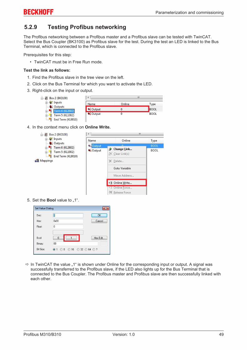
5.2.9 Testing Profibus networkingThe Profibus networking between a Profibus master and a Profibus slave can be tested with TwinCAT.Select the Bus Coupler (BK3100) as Profibus slave for the test. During the test an LED is linked to the BusTerminal, which is connected to the Profibus slave.
Prerequisites for this step:
• TwinCAT must be in Free Run mode.
Test the link as follows:1. Find the Profibus slave in the tree view on the left.2. Click on the Bus Terminal for which you want to activate the LED.3. Right-click on the input or output.
4. In the context menu click on Online Write.
5. Set the Bool value to „1“.
ð In TwinCAT the value „1“ is shown under Online for the corresponding input or output. A signal wassuccessfully transferred to the Profibus slave, if the LED also lights up for the Bus Terminal that isconnected to the Bus Coupler. The Profibus master and Profibus slave are then successfully linked witheach other.

Parameterization and commissioning
Profibus M310/B31050 Version: 1.0
5.2.10 'Turning' process dataThe process data are transferred in Intel format as standard. If the data are required in Motorola format, theyhave to be 'turned' accordingly. This step illustrates how to 'turn' the data in TwinCAT.
If the standard format is required, you can skip this step.
Prerequisites for this step:
• A parameterized slave.• A slave connected to a master. The master is added in TwinCAT and then scanned for the slave via
the master.
'Turn' the process data as follows:1. In the tree view, right-click on a variable containing data to be 'turned'.2. Click on the Flags tab.
3. Click on the required option. For WORD variables, only LOBYTE and HIBYTE can be swapped. ForDWORDs, the WORD can be swapped in addition.
ð In this way you can 'turn' process data. Use the following example to see how the data change for theindividual options.Example for DWORD.
Data of the slave Data which the master receivesOriginal data No option
selectedSwap Byte (blue) Swap Word (green) Swap both (blue and
green)0x01020304 0x01020304 0x02010403 0x03040102 0x04030201
The data can also be 'turned' in the PLC project, using the command ROR.Example for ST: VarProfibus:=ROR(VarAnalog,8); (*Both variables of type WORD*)

Parameterization and commissioning
Profibus M310/B310 51Version: 1.0
5.3 Parameterization with TwinCAT 3This section illustrates how Profibus devices can be parameterized with the aid of TwinCAT 3. A total ofthree devices are used for the example, including a Profibus master, to which two Profibus slaves areconnected.
First, the process of finding and selecting a target system in TwinCAT is illustrated. Next, a Profibus slave isadded and parameterized in TwinCAT, and the Profibus address of the slave is set. Then a PLC project iscreated and added in TwinCAT. Then, the variables from the PLC project are linked with the hardware, andthe finished configuration is loaded on the Profibus slave.
In the last step, the Profibus master is added in TwinCAT, and the two Profibus slaves are located via themaster. The process of testing the Profibus networking is then illustrated.
5.3.1 Searching for target systemsBefore you can work with the devices, you must connect your local computer to the target device. Then youcan search for devices with the help of the IP address or the host name.
The local PC and the target devices must be connected to the same network or directly to each other via anEthernet cable. In TwinCAT a search can be performed for all devices in this way and project planningsubsequently carried out.
Prerequisites for this step:
• TwinCAT 3 must be in Config mode.• IP address or host name of the device.
Search for the devices as follows:1. In the menu at the top click on File > New > Project and create a new TwinCAT XAE project.2. In the tree view on the left click on SYSTEM, and then Choose Target.
3. Click on Search (Ethernet).

Parameterization and commissioning
Profibus M310/B31052 Version: 1.0
4. Type the host name or the IP address of the device into the Enter Host Name / IP box and press[Enter].
5. Mark the device found and click on Add Route.
The Logon Information window appears.Enter the user name and password for the CX in the User Name and Password fields and click OK.
The following information is set as standard in CX devices:User name: Administrator Password: 1
6. If you do not wish to search for any further devices, click on Close to close the Add Route Dialog.The new device is displayed in the Choose Target System window.
7. Select the device you want to specify as target system and click OK.
ð You have successfully searched for a device in TwinCAT and inserted the device as the target system.The new target system and the host name are displayed in the menu bar.
Using this procedure you can search for all available devices and also switch between the target systemsat any time. Next, you can append the device to the tree view in TwinCAT.

Parameterization and commissioning
Profibus M310/B310 53Version: 1.0
5.3.2 Adding a Profibus slaveThe example shows a CX2020 Profibus slave with CX2500-B310 fieldbus module, connected to the Profibusmaster. In order to ensure that the Profibus slave is configured and subsequently detected by the Profibusmaster with all inputs and outputs, the Profibus slave first must be added in TwinCAT.
Prerequisites for this step:
• A scanned and selected target device with Profibus slave. This example uses a CX2020 with CX2500-B310 fieldbus module.
Add the Profibus slave as follows:1. Start TwinCAT and open an empty project.2. In the tree view on the left, right-click on I/O Devices.3. In the context menu click on Scan.
4. Select the devices you want to use and confirm the selection with OK.
5. Confirm the request with Yes, in order to look for boxes.Box 1 (CX2500-B310) is integrated. The Insert Module window appears.
6. Add modules such as 1 BYTE Slave-Out/Master-In and 1 BYTE Slave-In/Master-Out for your processimage.

Parameterization and commissioning
Profibus M310/B31054 Version: 1.0
7. Click on Cancel to close the Insert Module window.8. Confirm the request whether to enable FreeRun with Yes.
ð The Profibus slave was successfully added in TwinCAT 3 and is displayed in the tree view with the inputsand outputs.
You can add further variables by right-clicking on the box and then clicking on Add New Item in thecontext menu.
In the next step you can extend the process image by creating additional virtual slaves. Or you can setthe address, once the slave configuration is complete.

Parameterization and commissioning
Profibus M310/B310 55Version: 1.0
5.3.3 Creating a virtual slaveAdditional virtual slaves can be created on the same hardware interface. This enables more data to beexchanged with a Profibus master, or a connection with a second Profibus master can be established.
Each virtual slave is assigned a dedicated address via TwinCAT and is configured like an independentdevice for the Profibus master.
Prerequisites for this step:
• A Profibus slave, created in TwinCAT.
Create a virtual slave as follows:1. Right-click on a Profibus slave in the tree view on the left.
2. Click on Add New Item in the context menu.
ð A further box (virtual slave) is created.
Variables for the virtual slave can now be created. In the next step you can set the address for the slave.
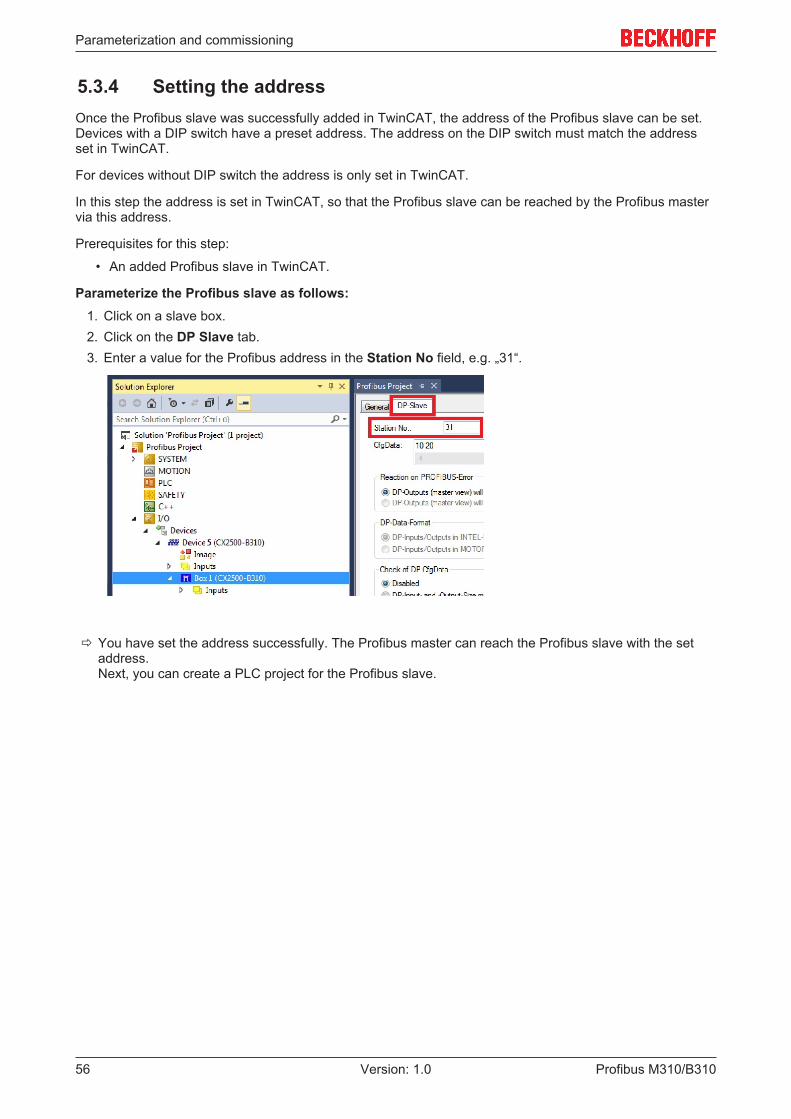
Parameterization and commissioning
Profibus M310/B31056 Version: 1.0
5.3.4 Setting the addressOnce the Profibus slave was successfully added in TwinCAT, the address of the Profibus slave can be set.Devices with a DIP switch have a preset address. The address on the DIP switch must match the addressset in TwinCAT.
For devices without DIP switch the address is only set in TwinCAT.
In this step the address is set in TwinCAT, so that the Profibus slave can be reached by the Profibus mastervia this address.
Prerequisites for this step:
• An added Profibus slave in TwinCAT.
Parameterize the Profibus slave as follows:1. Click on a slave box.2. Click on the DP Slave tab.3. Enter a value for the Profibus address in the Station No field, e.g. „31“.
ð You have set the address successfully. The Profibus master can reach the Profibus slave with the setaddress.Next, you can create a PLC project for the Profibus slave.

Parameterization and commissioning
Profibus M310/B310 57Version: 1.0
5.3.5 Creating a PLC projectThe next steps describe how to create a PLC project in TwinCAT and add it in the tree view.
Prerequisites for this step:
• A newly created TwinCAT XAE project.
Create a PLC project as follows:1. Right-click on PLC in the tree view.2. In the context menu click on Add New Item and select the Standard PLC Project.
3. In the tree view click on the newly created PLC project, then double-click on MAIN (PRG) under POUs.
4. Write a small program, as shown in the diagram below.

Parameterization and commissioning
Profibus M310/B31058 Version: 1.0
5. In the tree view right-click on the PLC project, then click on Build in the context menu.
ð You have successfully created a PLC project and added the project in TwinCAT. A PLC instance with thevariables for the inputs and outputs is created from the PLC project.
In the next step you can link the variables with the hardware.

Parameterization and commissioning
Profibus M310/B310 59Version: 1.0
5.3.6 Linking variablesOnce the PLC project was successfully added in the System Manager, you can link the newly created inputand output variables from the PLC project with the inputs and outputs of your hardware.
Prerequisites for this step:
• A PLC program attached in TwinCAT.
Link the variables as follows:1. Double-click on the input or output variables in the tree view under PLC.
The Attach Variable window appears and shows which inputs or outputs can be linked with thevariables from the PLC project.
2. Double-click on the inputs or outputs of the hardware in the Attach Variable window.Link the input variables with the inputs and the output variables with the outputs of the hardware.
Variables that are already linked are indicated with a small arrow icon in TwinCAT.3. In the toolbar click on Activate Configuration.
4. Confirm the request whether TwinCAT is to start in Free Run mode with Yes.ð You have successfully linked variables with the hardware. Use Activate Configuration to save and
activate the current configuration.
The configuration can now be loaded on the CX, in order to automatically start TwinCAT in Run mode,followed by the PLC project.
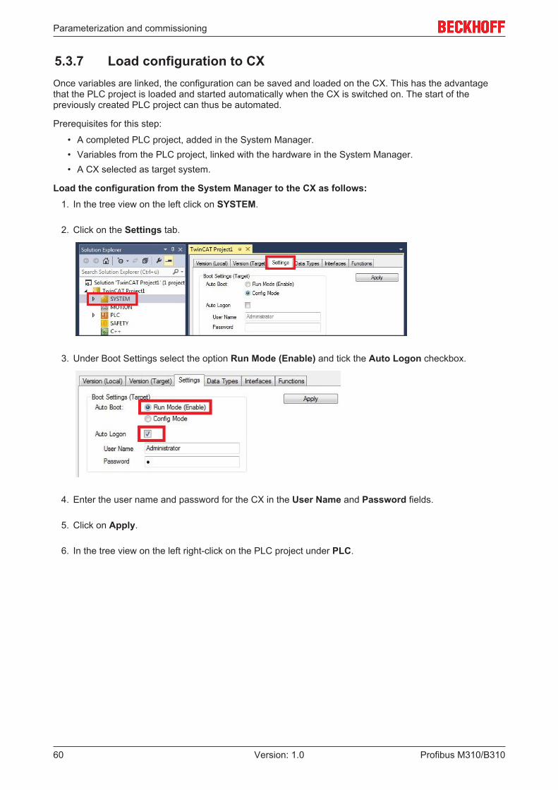
Parameterization and commissioning
Profibus M310/B31060 Version: 1.0
5.3.7 Load configuration to CXOnce variables are linked, the configuration can be saved and loaded on the CX. This has the advantagethat the PLC project is loaded and started automatically when the CX is switched on. The start of thepreviously created PLC project can thus be automated.
Prerequisites for this step:
• A completed PLC project, added in the System Manager.• Variables from the PLC project, linked with the hardware in the System Manager.• A CX selected as target system.
Load the configuration from the System Manager to the CX as follows:1. In the tree view on the left click on SYSTEM.
2. Click on the Settings tab.
3. Under Boot Settings select the option Run Mode (Enable) and tick the Auto Logon checkbox.
4. Enter the user name and password for the CX in the User Name and Password fields.
5. Click on Apply.
6. In the tree view on the left right-click on the PLC project under PLC.

Parameterization and commissioning
Profibus M310/B310 61Version: 1.0
7. In the context menu click on Autostart Boot Project.The setting is selected
8. Right-click on the project folder in the tree view.
9. In the context menu click on Auto Save to Target as Archive.The setting is selected.
ð You have successfully loaded the CX configuration. From now on, TwinCAT will start in Run mode andthe PLC project will start automatically.
Next, the Profibus master can be added in a new project in the System Manager and can then be used tofind Profibus slaves that have already been set up.

Parameterization and commissioning
Profibus M310/B31062 Version: 1.0
5.3.8 Adding a Profibus masterThe Profibus master is added with the TwinCAT System Manager, like the other devices. The attachedmaster can then be used to find all connected slaves. The following section illustrates how to add a Profibusmaster.
Prerequisites for this step:
• TwinCAT must be in Config mode.• A selected target system (in this example it is the Embedded PC CX2020-M310)
Add a Profibus master as follows:1. Start TwinCAT.2. In the tree view on the left, right-click on Devices.3. In the context menu click on Scan.
4. Select the devices you want to use and confirm the selection with OK.
5. Confirm the request whether to search for boxes with Yes.
ð All devices and slave boxes that are found are displayed in the tree view on the left, including BusTerminals connected to the devices or slave boxes.
Repeat the steps if not all devices are displayed. If not all devices and slave boxes are found despite therepeat operation, check the cabling of the devices and slave boxes.In the next step you can test the connection between Profibus master and Profibus slave.

Parameterization and commissioning
Profibus M310/B310 63Version: 1.0
5.3.9 Testing Profibus networkingThe Profibus networking between a Profibus master and a Profibus slave can be tested with TwinCAT.Select the Bus Coupler (BK3100) as Profibus slave for the test. During the test an LED is linked to the BusTerminal, which is connected to the Profibus slave.
Prerequisites for this step:
• TwinCAT must be in Free Run mode.
Test the link as follows:1. Find the Profibus slave in the tree view on the left.2. Click on the Bus Terminal for which you want to activate the LED.3. Right-click on the input or output.
4. In the context menu click on Online Write.
5. Set the Bool value to „1“.
ð In TwinCAT the value „1“ is shown under Online for the corresponding input or output. A signal wassuccessfully transferred to the Profibus slave, if the LED also lights up for the Bus Terminal that isconnected to the Bus Coupler. The Profibus master and Profibus slave are then successfully linked witheach other.

Parameterization and commissioning
Profibus M310/B31064 Version: 1.0
5.3.10 'Turning' process dataThe process data are transferred in Intel format as standard. If the data are required in Motorola format, theyhave to be 'turned' accordingly. This step illustrates how to 'turn' the data in TwinCAT.
If the standard format is required, you can skip this step.
Prerequisites for this step:
• A parameterized slave.• A slave connected to a master. The master is added in TwinCAT and then scanned for the slave via
the master.
'Turn' the process data as follows:1. In the tree view, right-click on a variable containing data to be 'turned'.2. Click on the Flags tab.
3. Click on the required option. For WORD variables, only LOBYTE and HIBYTE can be swapped. ForDWORDs, the WORD can be swapped in addition.
ð In this way you can 'turn' process data. Use the following example to see how the data change for theindividual options.Example for DWORD.
Data of the slave Data which the master receivesOriginal data No option
selectedSwap Byte (blue) Swap Word (green) Swap both (blue and
green)0x01020304 0x01020304 0x02010403 0x03040102 0x04030201
The data can also be 'turned' in the PLC project, using the command ROR.Example for ST: VarProfibus:=ROR(VarAnalog,8); (*Both variables of type WORD*)

Error handling and diagnostics
Profibus M310/B310 65Version: 1.0
6 Error handling and diagnosticsThe Error reactions section describes the reactions that will be given to slaves that do not answer or thatanswer incorrectly, to a PLC stop or at start-up.
The Master section describes the different diagnostic variables and how the diagnostic data can be read.The Slave section describes the diagnostic information, which indicated the state of the Profibus slave. Thesection also shows how the diagnostic data can be read. In addition, the error codes of the Profibus slaveare listed.
6.1 Diagnostic LEDsThe diagnostic LEDs of a PROFIBUS master and PROFIBUS slaves are described here. The labelling of thediagnostic LEDs on a CX2500 fieldbus module and an Embedded PC with optional interface is identical.
The LED description therefore only distinguishes between PROFIBUS master and PROFIBUS slave.
M310 (Master)
Display LED Colours MeaningBFShows the PROFIBUSstatus
Green, on PROFIBUS error-freeGreen, flashing PROFIBUS, at least one
slave in errorDIAIndicates PROFIBUSerror(s)
Red, lit No PROFIBUS configured
B310 (Slave)
Display LED Colours MeaningBFShows the PROFIBUSstatus
Green, on PROFIBUS in dataexchange
Green, flashing PROFIBUS, waiting forCfg data
DIAIndicates PROFIBUSerror(s)
Red, lit No PROFIBUS configured

Error handling and diagnostics
Profibus M310/B31066 Version: 1.0
6.2 Error ReactionsFailure of a slave
If a slave does not respond or the response is faulty, the master repeats the telegram several times, up tothe Max Retry limit (see: Bus Parameters (DP) [} 25]). If a faulty telegram is received, the master repeats thetelegram immediately. The slot time, which can be set on the same tab, indicates how long the master waitsfor a response from the slave.
For a Data_Exchange telegram with 12 Mbaud, a slot time of 1000 tbits and a Max Retry_Limit of 4(defaults), sending of the next telegram is delayed by the value:
TDelay = (4 x ((15 + number of outputs) x 11 + 1000) - (15 + number of inputs) x 11)/12 µs
The DpState of the slave is set to a value other than 0. The effect on the DP connection can be set (seebelow: response in the master).
Normal DP cycle (12 Mbaud, 5 slaves, 20 bytes in, 20 bytes out per slave on average)
First occurrence of a faulty DP cycle (slave 3 does not answer)
Subsequent DP cycles (slave 3 no longer in the polling list)
It can happen that the slave answers incorrectly, e.g. because, as a result of a local event on the slave, theDP connection has been removed. In this case the telegram is not repeated, but the next telegram is sent.The DpState is set to a value other than 0. The slave is removed from the poll list and no longer addressedin the next DP cycle. The send time of the next telegram changes, until the DP connection has been re-established.
Reactions in the master
The response in the master can be set for each slave (see: Features [} 31] tab). The response in the mastercan be set with the option NoAnswer Reaction.
Here you can specify whether the DP connection to the slave should be interrupted immediately or not untilthe DP watchdog time has elapsed without a correct receipt telegram (Data_Exchange telegram).
If the DP connection is to be interrupted immediately (Leave Data Exch, Features tab of the slave), the slaveis removed from the poll list discharged and no longer addressed in next DP cycle, until the DP connectionhas been re-established. At least seven telegrams are sent, in order to re-establish the DP connection. Theprocess usually takes at least 10-20 ms.

Error handling and diagnostics
Profibus M310/B310 67Version: 1.0
If the DP connection is not to be interrupted until the watchdog time has elapsed (Star in Data Exch for WDtime, Features tab of the slave), the system waits for a correct response for the watchdog time set for theslave. The slave is addressed once more in the next poll cycle. If the slave again fails to respond, no furtherrepeat telegram is sent.
It makes sense to wait for the watchdog time to elapse in situations where the PROFIBUS cycle should beas constant as possible in the event of a slave failure, and the failure of a slave can be tolerated for one orseveral cycles (e.g. in DP/MC mode (equidistant)). In this case the DP watchdog time for the slave should beset according to the tolerable outage time of the slave, and the Max Retry_Limit (DX) (Bus Parameter (DP)tab of master) should be set to 0.
Normal DP cycle (12 Mbaud, 5 slaves, an average of 20 bytes In, 20 bytes Out for each slave) in the"Stay in Data-Exch (for WD-Time)" mode
First faulty and subsequent DP cycles in the "Stay in Data-Exch (for WD-Time)" mode (slave 3 doesnot respond)
• Changes of the slave's input data if the slave does not respond correctlyHere you can specify whether the slave input data are set to 0 (inputs will be set to 0, Features [} 31]tab of the slave) or the old value is retained (No changes), if the slave fails. In either case the DpStateof the slave is set to value other than 0, so that the task can always recognize whether or not the datais valid. If a slave gives a faulty answer, the input data is always set to 0, independently of the setting ofChanges of the Input Data.
• Setting the slave's restart behaviour if the DP connection to the slave is removedHere you can specify whether the DP connection to a slave, whose DP connection was interrupted,should automatically be re-established, or whether this should be done manually through an ADSWriteControl call.This setting is available if the slave is not connected to a CX master.
• The reaction of the master if the DP connection to the slave is removedThis specifies whether removing the DP connection to a slave has no other effects (No Reaction, thedefault setting), or whether the master should enter the STOP state, thus removing the DP connectionsto all the slaves.This setting is available if the slave is not connected to a CX master.
Failure of the master• Monitoring in the PLC/IO task
In the presence of a persistent bus fault, the DP cycle can be extended up to 100 ms, even at 12Mbaud. CycleCounter status variable, which can be linked in the PLC, is available for monitoring theDP master. This variable is incremented by master after each DP cycle. The variable can be monitoredin the PLC monitored, in order to detect a failure of the master.
• Monitoring in the slaveA watchdog time can be enabled in the slave, in order to monitor the failure of the master or thetransfer to the PROFIBUS (see: Profibus [} 30] tab). The watchdog time must be set to at least twicethe maximum of the estimated DP cycle and the cycle time (see: CCAT PBM [} 24] tab).

Error handling and diagnostics
Profibus M310/B31068 Version: 1.0
Failure of the PLC/IO task
A distinction is made between a PLC stop, reaching a break point and a task stop (the I/O task and NC taskare only stopped when the entire system stops). In the case of a PLC stop, the output data is set to 0 by thePLC, whereas when a breakpoint is reached the data initially remains unchanged.
In the master the task is monitored with a task watchdog time (see: Startup/Fault settings [} 26] tab). If nonew data transfer takes place within this task watchdog time, the master switches to Clear state, accordingto the setting Reaction on Task Stop (outputs are set to 0 or to the safe state Fail_Safe = 1 in the GSD file).With the “Operate” setting, the outputs retain the last value.
Start-up behaviour
The DP connections to all the slaves are established when the TwinCAT system starts up. Until the highestpriority task that is involved has not been started, the master still does not send any Data_Exchangetelegrams even after the DP connection has been established, and sends only diagnostic telegrams. Assoon as the highest priority task has transferred data once, and the DP connection for the corresponding DPslave has been established, the master cyclically (with the highest priority assigned task) sends oneData_Exchange telegram to each of the corresponding slaves.

Error handling and diagnostics
Profibus M310/B310 69Version: 1.0
6.3 MasterDiagnostic variables
The master possesses a variety of diagnostic variables that describe the state of the master and of theProfibus. They can be linked in the PLC:
CdlInfo:
Variable DescriptioncycleCounter Is incremented at the end of each PROFIBUS cycle in order that this variable can indicate
whether the last cycle was completed before the task was started.error Indicates the number of slaves, with which no data exchange could take place during the
last cycle. The variable BoxState of the slaves only has to be checked, if this value is not0.
actualCycleTime
Shows the current cycle time in 4/25 µs. This variable is only updated, if all slaves are indata exchange (i.e. CdlInfo.error is 0).
actualModulo Shows the current modulo. This variable is only relevant, if the slaves are prioritized.
Counter: These variables are only used for the redundancy mode.
Variable DescriptionCounter[0-1] These variables are reserved for extensions.Counter[2] This variable counts received telegrams. The counter is incremented by 1 whenever an
error-free PROFIBUS telegram is received.Counter[3] This variable counts the telegrams received by the primary master. The counter is
incremented by 1, whenever the primary master receives an error-free telegram (Theprimary master has the same address as the redundancy master).
Counter[4] This variable is a timeout counter. The counter is incremented by 1 whenever a timeoutoccurs on the PROFIBUS.
Counter[5-7] These variables are reserved for extensions.
DiagFlag:

Error handling and diagnostics
Profibus M310/B31070 Version: 1.0
Variable DescriptionDiagFlag Indicates whether the master diagnostic information has changed. In this case the control
program reads the information via ADS, and the variable "DiagFlag" is then reset.0 = diagnostic data unchanged.1 = diagnostic data have changed. Use ADS Read to read the data.
GlobalState:
Variable DescriptionGlobalState[0] Indicates the state of the master.
0 = RUN1 = RESET2 = OFFLINE3 = STOP
GlobalState[1] Indicates the number of detected bus errors.GlobalState[2] Reserved for extensions.GlobalState[3] Reserved for extensions.
CycleFailedCounter:
Variable DescriptionCycleFailedCounter
This counter indicates how often the PROFIBUS cycle was not complete on startup of theTwinCAT task.
StartRedundantMasterFlag: Is for the redundancy mode.
Variable DescriptionStartRedundantMasterFlag
If the value is set to 1 (True), the redundancy master on the PROFIBUS becomes active. Ifthe value is 0 (False), the redundancy master is offline.
6.3.1 ADS-Interface
ADS NetId of the PROFIBUS interface
A NetId is required for the ADS communication. This can be found in the ADS tab of the PROFIBUSinterface in the TwinCAT System Manager.
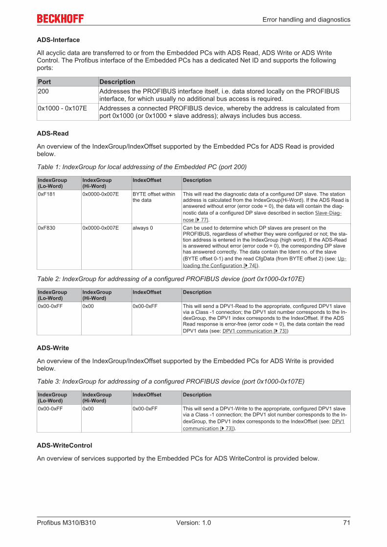
Error handling and diagnostics
Profibus M310/B310 71Version: 1.0
ADS-Interface
All acyclic data are transferred to or from the Embedded PCs with ADS Read, ADS Write or ADS WriteControl. The Profibus interface of the Embedded PCs has a dedicated Net ID and supports the followingports:
Port Description200 Addresses the PROFIBUS interface itself, i.e. data stored locally on the PROFIBUS
interface, for which usually no additional bus access is required.0x1000 - 0x107E Addresses a connected PROFIBUS device, whereby the address is calculated from
port 0x1000 (or 0x1000 + slave address); always includes bus access.
ADS-Read
An overview of the IndexGroup/IndexOffset supported by the Embedded PCs for ADS Read is providedbelow.
Table 1: IndexGroup for local addressing of the Embedded PC (port 200)
IndexGroup(Lo-Word)
IndexGroup(Hi-Word)
IndexOffset Description
0xF181 0x0000-0x007E BYTE offset withinthe data
This will read the diagnostic data of a configured DP slave. The stationaddress is calculated from the IndexGroup(Hi-Word). If the ADS Read isanswered without error (error code = 0), the data will contain the diag-nostic data of a configured DP slave described in section Slave-Diag-nose [} 77].
0xF830 0x0000-0x007E always 0 Can be used to determine which DP slaves are present on thePROFIBUS, regardless of whether they were configured or not; the sta-tion address is entered in the IndexGroup (high word). If the ADS-Readis answered without error (error code = 0), the corresponding DP slavehas answered correctly. The data contain the Ident no. of the slave(BYTE offset 0-1) and the read CfgData (from BYTE offset 2) (see: Up-loading the Configuration [} 74]).
Table 2: IndexGroup for addressing of a configured PROFIBUS device (port 0x1000-0x107E)
IndexGroup(Lo-Word)
IndexGroup(Hi-Word)
IndexOffset Description
0x00-0xFF 0x00 0x00-0xFF This will send a DPV1-Read to the appropriate, configured DPV1 slavevia a Class -1 connection; the DPV1 slot number corresponds to the In-dexGroup, the DPV1 index corresponds to the IndexOffset. If the ADSRead response is error-free (error code = 0), the data contain the readDPV1 data (see: DPV1 communication [} 73])
ADS-Write
An overview of the IndexGroup/IndexOffset supported by the Embedded PCs for ADS Write is providedbelow.
Table 3: IndexGroup for addressing of a configured PROFIBUS device (port 0x1000-0x107E)
IndexGroup(Lo-Word)
IndexGroup(Hi-Word)
IndexOffset Description
0x00-0xFF 0x00 0x00-0xFF This will send a DPV1-Write to the appropriate, configured DPV1 slavevia a Class -1 connection; the DPV1 slot number corresponds to the In-dexGroup, the DPV1 index corresponds to the IndexOffset (see: DPV1communication [} 73]).
ADS-WriteControl
An overview of services supported by the Embedded PCs for ADS WriteControl is provided below.

Error handling and diagnostics
Profibus M310/B31072 Version: 1.0
Table 4: ADS-WriteControl for addressing a configured PROFIBUS device (port 0x1000-0x107E)
AdsState DeviceState State of the slave DescriptionSTOP (6) 0x00 RUN (5) This will stop the slave, i.e. the process data connection to the relevant
DP slave (Data_Exchange) is removed (with SetPrm,Unlock).RUN (5) 0x00 STOP (6) This will restart the slave after a stop, i.e. the process data connection
to the relevant DP slave (Data_Exchange) is re-established (normal DPstart-up).

Error handling and diagnostics
Profibus M310/B310 73Version: 1.0
6.3.2 DPV1 communicationOn a C1 connection, the master supports the Read and Write services, and on the C2 connection it supportsthe Read, Write, Data_Transport, Initiate and Abort services.
C1 Connection (MSAC-C1)
The C1 connection is reserved for the master that cyclically exchanges data with the slave (C1 master). Inorder for a slave to be able to use the C1 connection, the slave must support DPV1 (this means that the line"DPV1_Slave = 1" and the key word "C1_Max_Data_Len" with an appropriate length must be in the GSDfile). If it is also generally necessary to activate the C1 functionality by setting bit 7 in the PrmData byte 0 forthe corresponding slave (this is done automatically for those Beckhoff devices that support DPV1).
MSAC-C1-Read is shown in ADS-Read, and MSAC-C1-Write is represented in ADS-Write:
MSAC-C1 Read
ADS-Read parameters MeaningNet-ID Net-ID of the master (see the device's ADS tab)Port 0x1000 + station address of the slaveIndexGroup Slot number (DPV1 parameter)IndexOffset Index (DPV1 parameter)Length Length of the data that is to be readData In response: data that has been read
MSAC-C1 Write
ADS-Write parameters MeaningNet-ID Net-ID of the master (see the device's ADS tab)Port 0x1000 + station address of the slaveIndexGroup Slot number (DPV1 parameter)IndexOffset Index (DPV1 parameter)Length Length of the data that is to be writtenData In request: data that is to be written

Error handling and diagnostics
Profibus M310/B31074 Version: 1.0
6.3.3 Uploading the ConfigurationDuring operation the PROFIBUS can be scanned for new devices via ADS Read:
ADS-Read parameters MeaningNet-ID Net-ID of the master (see the device's ADS tab)Port 200IndexGroup 0x00yyF830 (yy = station address, Beckhoff devices
provide the same information as other devices)IndexOffset 0Length 1538Data Configuration data of the slave
If the device is from another manufacturer, or if the IndexGroup indicates that Beckhoff devices are tobehave in exactly the same way as devices from other manufacturers, then the following information isreturned in the ADS read response:
Offset Description0 -1 12 - 7 DP diagnostic data bytes 0-5 (see Slave-Diagnose
[} 77])8 - 251 DP configuration data (CfgData)

Error handling and diagnostics
Profibus M310/B310 75Version: 1.0
6.4 SlaveDiagnostic variables
The slave features various diagnostic variables, which describe the state of the slave and the Profibus andcan be linked in the PLC:
DpState:

Error handling and diagnostics
Profibus M310/B31076 Version: 1.0
Value Description0 No Error:
Station is in data exchange.1 Station deactivated:
The slave was deactivated.2 Station not exists:
Slave does not respond. Check whether the slave is switched on, the cabling is OK and the stationaddress is correct.
3 Master lock:The slave is in data exchange with another master.
4 Invalid slave response:Incorrect response from the slave. Occurs temporarily if the slave has terminated the dataexchange due to a local event.
5 Parameter fault:Indicates a paramétrisation error.
6 Not supported:A DP function is not supported. Check whether the GSD file and the station address is correct.
7 Config fault:Indicates a configuration error. Check whether the added terminals or modules are OK.
8 Station not ready:The device is starting up. This is displayed temporarily during startup.
9 Static diagnosis:The slave indicates a static diagnosis and is currently unable to provide valid data. Check theoperating state at the slave.
10 Diagnosis overflow:The slave indicates a diagnostics overflow. Read the diagnostic data with ADS Read and checkthe operating state of the slave.
11 Physical fault:Indicates a physical error in the response from a slave. Check the cabling.
12 Data-Exchange left:The data transfer was not completed.
13 Severe bus fault:Indicates a serious bus error. Please check the cabling.
14 Telegram fault:The slave responds with an invalid telegram.
15 Station has no resources:The slave has insufficient resources for the telegram. Check whether the GSD file is correct.
16 Service not activated:Occurs if the slave terminates the data exchange due to a local event. Check whether DPfunctionality is disabled for the slave.
17 Unexpected telegram:Unexpected telegram; can occur temporarily, if two PROFIBUS networks are linked, or checkwhether bus times in the second master are set the identically
18 Station ready:Occurs temporarily during startup, as long as the task has not yet started.
31 only for EtherCAT gateways:WC state of the cyclic EtherCAT frame is 1.
128 Slave waiting for data transfer:The slave was parameterized and configured, but has not yet received a data exchange telegram.
129 Slave waiting for configuration:The slave was parameterized, but has not yet received a Chk_Cfg telegram.
130 Slave waiting for parameter:The slave was not yet parameterized and is waiting for a Set_Prm (Lock) telegram.
131 Slave waiting for baud rate:The baud rate was not set.

Error handling and diagnostics
Profibus M310/B310 77Version: 1.0
Value Description132 Slave waiting for station no. from PLC:
The Profibus address was not set.
ExtDiagFlag:
Value Description0 Diagnostic data have not changed.1 Diagnostic data have changed. Use ADS Read to read the data.
6.4.1 Slave-Diagnose
DP-State
Each DP slave has a status variable that indicates the current state of that DP slave. This status ismaintained in real time, so that it is always adapted to the current DP slave data, and can be linked to a PLCvariable (-> DpState of the slave):
Diagnostic data
Any DP slave can acyclically report DP diagnostic data during data exchange operation. The slave here setsthe Diag_Flag in the response to the cyclic Data_Exchange telegram, as a result of which the DP masterautomatically reads the DP diagnostic data from the slave. This does not affect the Data-Exchange cycle inthe Beckhoff DP master, because the DP diagnostic telegram is sent at the end of the cyclic Data-Exchangecycle, and before the beginning of the next cycle. If the DP diagnostic data read from the slave has changedfrom its previous state, the DP master sets the ExtDiagFlag variable, which can be linked to a variable in thecontroller program.
The DP slave's current diagnostic data is displayed in the system manager on the slave's Diag tab. It canalso be read by the controller program via ADS, which will cause the "ExtDiagFlag" flag to be reset oncemore:
ADS-Read parameters MeaningNet-ID Net-ID of the master (see the device's ADS tab)Port 200IndexGroup 0x00yyF181 (yy = station address of the slave)IndexOffset Offset within the diagnosis dataLength Length of the diagnostic data that is to be readData Diagnostic data
The diagnostic data contains the slave statistics (32 bytes) and the DP diagnostic data sent by the slave (upto 244 bytes), and is constructed as follows:

Error handling and diagnostics
Profibus M310/B31078 Version: 1.0
Offset MeaningSlave statistics0 Receive Error Counter (WORD): The number of faulty telegrams occurring while
communicating with this slave.2 Repeat counter[8] (WORD): The repeat counters indicate how many repeats have had
to be made, and how often. Repeat Counter[0] indicates how often it has beennecessary to repeat a telegram for this slave once, Repeat Counter[1] shows howoften a telegram for this slave has had to be repeated twice, and so on. The maximumnumber of retries is set with the parameter Max Retry Limit (see Bus parametersdialog). The value range is from 0 to 8, therefore there are 8 repeat counters (for 1 to8 retries)
18 reserved for extensions20 NoAnswer Counter (DWORD): The number of telegrams in communication with this
slave that have not received an answer. The first time that a slave fails to answer, thetelegram is repeated up to MaxRetryLimit times, but if it does not answer even then,further telegrams are not repeated.
24-27 Last-DPV1-Error[4] (BYTE): The most recent faulty DPV1 response is entered here(byte 0: DPV1 service (bit 7 is set, thus indicating an error), byte 1: Error_Decode,byte 2: Error_Code_1 (Error_Class/Error_Code), byte 3: Error_Code_2), seedescription of the DPV1 error codes [} 84]
27-31 reserved for extensionsfrom 32 DP diagnostic data
There follows a description of the DP diagnostic data

Error handling and diagnostics
Profibus M310/B310 79Version: 1.0
Offset Meaning0x00.0 StationNonExistent: slave did not reply to the last telegram0x00.1 StationNotReady: slave still processing the Set_Prm / Chk_Cfg telegram0x00.2 CfgFault: slave signaling a configuration error0x00.3 ExtDiag: extended DiagData available and valid0x00.4 NotSupported: slave does not support a feature requested via Set_Prm or
Global_Control0x00.5 InvalidSlaveResponse: slave response not DP-compatible0x00.6 PrmFault: slave reports a paramétrisation error0x00.7 MasterLock: slave currently exchanging data with another master0x01.0 PrmReq: re-parameterize and reconfigure slave0x01.1 StatDiag: slave signaling static diagnosis / DPV1 slave application not yet ready for
data exchange0x01.2 PROFIBUS DP slave0x01.3 WdOn: DP watchdog on0x01.4 FreezeMode: DP slave in freeze mode0x01.5 SyncMode: DP slave in sync mode0x01.6 reserved0x01.7 Deactivated: DP slave has been deactivated0x02.0 reserved0x02.1 reserved0x02.2 reserved0x02.3 reserved0x02.4 reserved0x02.5 reserved0x02.6 reserved0x02.7 ExtDiagOverflow: too much extended data present0x03 MasterAdd: station address of master with which slave is exchanging data0x04,0x05 IdentNumberab 0x06 Extended DiagData
Extended DiagData
A distinction is made in the Extended DiagData between identification diagnosis, channel diagnosis andmanufacturer-specific diagnosis. The first byte indicates the type of the diagnosis and the length of theassociated data. Several diagnostic types can also follow one another in the Extended DiagData.
Header-Byte
Bit Meaning0-5 Length of the associated diagnostic data, including header byte6-7 0 = manufacturer-specific diagnosis (DPV1 is not supported) or DPV1 diagnosis
(DPV1 is supported (DPV1_Enable = 1) in associated GSD file)Module diagnosisChannel diagnosisRevision number
Manufacturer-specific diagnosis
The structure of the manufacturer-specific diagnosis may be found in the documentation for the DP slave.

Error handling and diagnostics
Profibus M310/B31080 Version: 1.0
6.4.2 Individual diagnostic dataThe controller enables sending of diagnostic data from the PLC. You can write your own diagnostic messagefor the master and fill it individually with data (see Device-specific diagnostic data below).
DP Diagnostic Data (DiagData)
Note
Transmission of the diagnostic telegramA diagnostic telegram is only transferred to the controller when the diagnostic data havechanged.
The DP diagnostic data consists of six bytes of DP standard diagnosis, along with up to 238 bytes of device-specific diagnostic data.
When the DP diagnostic data changes, the slave reports this fact to the master, and the master willautomatically fetch the changed diagnostic data. This means that DP diagnostic data is not included in theDP process data in real-time, but is always sent to the controller a few cycles later.
In TwinCAT the DP diagnostic data are read by the DP master connection via ADS.
DP standard diagnostic data
Offset Meaning0x00.0 StationNonExistent: slave did not reply to the last telegram0x00.1 StationNotReady: slave still processing the Set_Prm / Chk_Cfg telegram0x00.2 CfgFault: slave signaling a configuration error0x00.3 ExtDiag: extended DiagData available and valid0x00.4 NotSupported: slave does not support a feature requested via Set_Prm or
Global_Control0x00.5 InvalidSlaveResponse: slave response not DP-compatible0x00.6 PrmFault: slave reports a paramétrisation error0x00.7 MasterLock: slave currently exchanging data with another master0x01.0 PrmReq: re-parameterize and reconfigure slave0x01.1 StatDiag: slave signaling static diagnosis / DPV1 slave application not yet ready for
data exchange0x01.2 PROFIBUS DP slave0x01.3 WdOn: DP watchdog on0x01.4 FreezeMode: DP slave in freeze mode0x01.5 SyncMode: DP slave in sync mode0x01.6 reserved0x01.7 Deactivated: DP slave has been deactivated0x02.0 reserved0x02.1 reserved0x02.2 reserved0x02.3 reserved0x02.4 reserved0x02.5 reserved0x02.6 reserved0x02.7 ExtDiagOverflow: too much extended data present0x03 MasterAdd: station address of master with which slave is exchanging data0x04,0x05 IdentNumberab 0x06 Device-specific diagnostic data (extended DiagData)

Error handling and diagnostics
Profibus M310/B310 81Version: 1.0
Device-specific diagnostic data
Note
Transmission of user-specific diagnostic dataByte 0 of the data must contain a 0x08. Bytes 1 to 5 are overwritten by the CX. Byte 6 andhigher can contain your own diagnostic data. Make sure that your own diagnostic data con-forms to the PROFIBUS standard for user-specific diagnosis.
The ADSWRITE block is used for sending diagnostic data. The current DP diagnosis sent to the bus can beread via ADSREAD. Please note that an additional 6 bytes (PROFIBUS standard DP diagnosis) are requiredfor reading, i.e. the number of bytes that are read exceeds the number of bytes that were written by 6. TheADS parameters for the read process are identical.
Input parameters DescriptionNETID local NetId of the Profibus devicePORT number 0x1000+slave addressIDXGRP 16#F481IDXOFFS 0LEN max. 244SRCADDR Pointer to diagnostic data

Error handling and diagnostics
Profibus M310/B31082 Version: 1.0
6.4.3 DP-V1 communication
C1 Connection (MSAC-C1)
The C1 connection is reserved for the master that cyclically exchanges data with the slave (C1 master). Inorder for a slave to be able to use the C1 connection, the slave must support DPV1 (this means that the line"DPV1_Slave = 1" and the key word "C1_Max_Data_Len" with an appropriate length must be in the GSDfile). If it is also generally necessary to activate the C1 functionality by setting bit 7 in the PrmData byte 0(see the slave's PROFIBUS tab) for the corresponding slave (this is done automatically for those Beckhoffdevices that support DPV1).
MSAC-C1-Read is mapped on ADS-Readind, MSAC-C1-Write on ADS-Writeinc:
PROFIBUS DPV1
The DP slave supports a DPV1-MSAC_C1 server connection that is established along with the cyclicconnection. This can be used so that larger quantities of acyclic data can be transferred alongside the cyclicdata. A DPV1 read telegram received by the master is reported to the PLC as an ADS read indication, whilea DPV1 write telegram is reported to the PLC as an ADS write indication. The PLC program is thenresponsible for the read or write response. To do this, the ADS read response or ADS write responsefunctions are to be called.
Settings in the System Manager
In order to transport the DP-V1 services into the PLC this function must be activated by specifying the port.
Port 0 deactivated, 802 PLC runtime 1, task 1
MSAC-C1 Read
A DPV1-MSAC_C1 read indication is represented in an ADS read indication as follows:

Error handling and diagnostics
Profibus M310/B310 83Version: 1.0
ADS read indication parameter MeaningSource-Net-ID (NETID) Net-ID of the slave (see the device’s ADS tab)Source-Port (PORT) 0x1000+slave addressInvoke-ID (INVOKEID) A unique number that must reappear in the responseIndexGroup (IDXGRP) Slot number (DPV1 parameter)IndexOffset (IDXOFFS) Index (DPV1 parameter)Length (LENGTH) Length of the data that is to be read
An ADS read response is represented in a DPV1-MSAC_C1 read response as follows:
ADS read response parameter MeaningDestination-Net-ID (NETID) Net-ID of the slave (see the device’s ADS tab)Destination-Port (PORT) 0x1000+slave addressInvoke-ID (INVOKEID) A unique number, as under indicationResult (RESULT) Result of the read: 0 = no error, otherwise: bits 0-15 =
standard ADS error codes, bits 16-23 =Error_Code_1, bits 24-31 = Error_Code_2,See: DP-V1 error codes [} 84].
Length (LENGTH) Length of the data that has been readData (DATAADDR) read data
MSAC-C1 Write
A DPV1-MSAC_C1 write indication is represented in an ADS write indication as follows:
ADS write indication parameter MeaningSource-Net-ID (NETID) Net-ID of the slave (see the device’s ADS tab)Source-Port (PORT) 0x1000+slave addressInvoke-ID (INVOKEID) A unique number that must reappear in the responseIndexGroup (IDXGRP) Slot number (DPV1 parameter)IndexOffset (IDXOFFS) Index (DPV1 parameter)Length (LENGTH) Length of the data that is to be writtenData (DATAADDR) data that is to be written
An ADS read response is represented in a DPV1-MSAC_C1 read response as follows:
ADS read response parameter MeaningDestination-Net-ID (NETID) Net-ID of the slave (see the device’s ADS tab)Destination-Port (PORT) 0x1000+slave addressInvoke-ID (INVOKEID) A unique number, as under indicationResult (RESULT) Result of the read: 0 = no error, otherwise: bits 0-15 =
standard ADS error codes, bits 16-23 =Error_Code_1, bits 24-31 = Error_Code_2,See: DP-V1 error codes [} 84].
Length (LENGTH) Length of the data that has been read

Error handling and diagnostics
Profibus M310/B31084 Version: 1.0
6.4.4 DP-V1 error codesIn the event of an incorrect DPV1 access, the slave replies with 4 bytes of data (any values that are notdescribed here are not defined in the DPV1 standard, and are therefore to be found in the slave's manual).
byte 0 DPV1 service0xD1 Data_Transport0xD7 Initiate0xDE Read0xDF Write
byte 1 Error_Decode0x80 DPV10xFE FMS0xFF HART
byte 2 Error_Code_1Error-Class (bits 4-7) Error-Code (bits 0-3)0x0A 0x00 Application, Read Error
0x01 Application, Write Error0x02 Application, Module Failure0x08 Application, Version Conflict0x09 Application, Feature Not Supported
0x0B 0x00 Access, Invalid Index0x01 Access, Write Length Error0x02 Access, Invalid Slot0x03 Access, Type Conflict0x04 Access, Invalid Area0x05 Access, State Conflict0x06 Access, Access Denied0x07 Access, Invalid Range0x08 Access, Invalid Parameter0x09 Access, Invalid Type
0x0C 0x00 Resource, Read Constrain Conflict0x01 Resource, Write Constrain Conflict0x02 Resource, Busy0x03 Resource, Unavailable

Appendix
Profibus M310/B310 85Version: 1.0
7 Appendix
7.1 AccessoriesCables and connectors for the connection of the Profibus components.
Connector
Item number DescriptionZB3100 9-pin D sub connector up to 12 Mbaud, with switchable
termination resistorZB3101 9-pin D sub connector up to 12 Mbaud, with programming
interfaceZB3102 9-pin D sub connector up to 12 Mbaud, with switchable
termination resistor, inverse PROFIBUS plug connectorZS1031-3000 9-pin D sub connector up to 12 Mbaud, with switchable
termination resistor (other design)ZS1031-3500 Fiber-optic connector for BK35xx (included with the Bus
Coupler)
Cable
Item number DescriptionZB3200 PROFIBUS cable, 12 Mbaud, 1 x 2 x 0.64 mm² for fixed
installationZB3300 PROFIBUS cable, 12 Mbaud, 2 x 0.25; 3 x 0.75 mm², 5-core,
suitable for drag chains
Fiber-optic cable for Bus Coupler BK3500 (PROFIBUS)
Item number DescriptionZ1100 1-core, 100 μm synthetic fiber, diameter 2.2 mmZ1101 Synthetic fiber-optic cable, core ø 1000 μm, PU coating ø 5.5
mm, Kevlar strain reliefZ1102 as Z1101, on drum, length = 500 mZ1121 Synthetic fiber optic cable, 1000 μm core, 2-core, PU coating,
diameter 5.5 mm

Appendix
Profibus M310/B31086 Version: 1.0
7.2 CertificationsAll products of the Embedded PC family are CE, UL and EAC certified. Since the product family iscontinuously developed further, we are unable to provide a full listing here. The current list of certifiedproducts can be found at www.beckhoff.com.
FCC Approvals for the United States of America
FCC: Federal Communications Commission Radio Frequency Interference Statement
This equipment has been tested and found to comply with the limits for a Class A digital device, pursuant toPart 15 of the FCC Rules. These limits are designed to provide reasonable protection against harmfulinterference when the equipment is operated in a commercial environment. This equipment generates, uses,and can radiate radio frequency energy and, if not installed and used in accordance with the instructionmanual, may cause harmful interference to radio communications. Operation of this equipment in aresidential area is likely to cause harmful interference in which case the user will be required to correct theinterference at his own expense.
FCC Approval for Canada
FCC: Canadian Notice
This equipment does not exceed the Class A limits for radiated emissions as described in the RadioInterference Regulations of the Canadian Department of Communications.
Appendix
Profibus M310/B310 87Version: 1.0
7.3 Support and ServiceBeckhoff and their partners around the world offer comprehensive support and service, making available fastand competent assistance with all questions related to Beckhoff products and system solutions.
Beckhoff's branch offices and representatives
Please contact your Beckhoff branch office or representative for local support and service on Beckhoffproducts!
The addresses of Beckhoff's branch offices and representatives round the world can be found on her internetpages:http://www.beckhoff.com
You will also find further documentation for Beckhoff components there.
Beckhoff Headquarters
Beckhoff Automation GmbH & Co. KG
Huelshorstweg 2033415 VerlGermany
Phone: +49(0)5246/963-0Fax: +49(0)5246/963-198e-mail: [email protected]
Beckhoff Support
Support offers you comprehensive technical assistance, helping you not only with the application ofindividual Beckhoff products, but also with other, wide-ranging services:
• support• design, programming and commissioning of complex automation systems• and extensive training program for Beckhoff system components
Hotline: +49(0)5246/963-157Fax: +49(0)5246/963-9157e-mail: [email protected]
Beckhoff Service
The Beckhoff Service Center supports you in all matters of after-sales service:
• on-site service• repair service• spare parts service• hotline service
Hotline: +49(0)5246/963-460Fax: +49(0)5246/963-479e-mail: [email protected]