manual placa base asus rampage ii gene
TRANSCRIPT

8/9/2019 Manual Placa Base Asus Rampage II Gene
http://slidepdf.com/reader/full/manual-placa-base-asus-rampage-ii-gene 1/176
M o
t h e r
b o a r d
Rampage IIGENE

8/9/2019 Manual Placa Base Asus Rampage II Gene
http://slidepdf.com/reader/full/manual-placa-base-asus-rampage-ii-gene 2/176
ii
E4504
First EditionFebruary 2009
Copyright © 2009 ASUSTeK COMPUTER INC. All Rights Reserved.No part of this manual, including the products and software described in it, may be reproduced,transmitted, transcribed, stored in a retrieval system, or translated into any language in any form or by anymeans, except documentation kept by the purchaser for backup purposes, without the express writtenpermission of ASUSTeK COMPUTER INC. (“ASUS”).Product warranty or service will not be extended if: (1) the product is repaired, modi ed or altered, unlesssuch repair, modi cation of alteration is authorized in writing by ASUS; or (2) the serial number of theproduct is defaced or missing.ASUS PROVIDES THIS MANUAL “AS IS” WITHOUT WARRANTY OF ANY KIND, EITHER EXPRESSOR IMPLIED, INCLUDING BUT NOT LIMITED TO THE IMPLIED WARRANTIES OR CONDITIONS OFMERCHANTABILITY OR FITNESS FOR A PARTICULAR PURPOSE. IN NO EVENT SHALL ASUS, ITSDIRECTORS, OFFICERS, EMPLOYEES OR AGENTS BE LIABLE FOR ANY INDIRECT, SPECIAL,INCIDENTAL, OR CONSEQUENTIAL DAMAGES (INCLUDING DAMAGES FOR LOSS OF PROFITS,LOSS OF BUSINESS, LOSS OF USE OR DATA, INTERRUPTION OF BUSINESS AND THE LIKE),EVEN IF ASUS HAS BEEN ADVISED OF THE POSSIBILITY OF SUCH DAMAGES ARISING FROM ANYDEFECT OR ERROR IN THIS MANUAL OR PRODUCT.SPECIFICATIONS AND INFORMATION CONTAINED IN THIS MANUAL ARE FURNISHED FORINFORMATIONAL USE ONLY, AND ARE SUBJECT TO CHANGE AT ANY TIME WITHOUT NOTICE,AND SHOULD NOT BE CONSTRUED AS A COMMITMENT BY ASUS. ASUS ASSUMES NORESPONSIBILITY OR LIABILITY FOR ANY ERRORS OR INACCURACIES THAT MAY APPEAR IN THISMANUAL, INCLUDING THE PRODUCTS AND SOFTWARE DESCRIBED IN IT.Products and corporate names appearing in this manual may or may not be registered trademarks orcopyrights of their respective companies, and are used only for identi cation or explanation and to theowners’ bene t, without intent to infringe.

8/9/2019 Manual Placa Base Asus Rampage II Gene
http://slidepdf.com/reader/full/manual-placa-base-asus-rampage-ii-gene 3/176
iii
ContentsContents ...................................................................................................... iiiNotices ....................................................................................................... viiiSafety information ...................................................................................... ixAbout this guide .......................................................................................... xRampage II GENE speci cations summary ............................................ xii
Chapter 1: Product introduction1.1 Welcome! ...................................................................................... 1-11.2 Package contents ......................................................................... 1-11.3 Special features ............................................................................ 1-2
1.3.1 Product highlights ........................................................... 1-21.3.2 ROG Intelligent Performance & Overclocking features ... 1-31.3.3 ROG unique features ...................................................... 1-41.3.4 ASUS special features .................................................... 1-5
Chapter 2: Hardware information2.1 Before you proceed ..................................................................... 2-12.2 Motherboard overview ................................................................. 2-6
2.2.1 Motherboard layout ......................................................... 2-62.2.2 Layout contents ............................................................... 2-72.2.3 Placement direction ........................................................ 2-82.2.4 Screw holes .................................................................... 2-8
2.3 Central Processing Unit (CPU) ................................................... 2-92.3.1 Installing the CPU ......................................................... 2-102.3.2 Installing the CPU heatsink and fan .............................. 2-13
2.3.3 Uninstalling the CPU heatsink and fan ......................... 2-142.4 System memory ......................................................................... 2-15
2.4.1 Overview ....................................................................... 2-152.4.2 Memory con gurations .................................................. 2-162.4.3 Installing a DIMM .......................................................... 2-222.4.4 Removing a DIMM ........................................................ 2-22
2.5 Expansion slots .......................................................................... 2-232.5.1 Installing an expansion card ......................................... 2-232.5.2 Con guring an expansion card ..................................... 2-232.5.3 Interrupt assignments ................................................... 2-242.5.4 PCI slot ......................................................................... 2-25

8/9/2019 Manual Placa Base Asus Rampage II Gene
http://slidepdf.com/reader/full/manual-placa-base-asus-rampage-ii-gene 4/176
iv
Contents2.5.5 PCI Express x4 slot ....................................................... 2-252.5.6 PCI Express 2.0 x16 slots ............................................. 2-25
2.6 Jumper ........................................................................................ 2-272.7 Connectors ................................................................................. 2-28
2.7.1 Rear panel connectors .................................................. 2-282.7.2 Internal connectors ....................................................... 2-302.7.3 Onboard switches ......................................................... 2-402.7.4 Installing I/O shield and LCD Poster ............................. 2-42
2.8 Starting up for the rst time ...................................................... 2-432.9 Turning off the computer ........................................................... 2-44
2.9.1 Using the OS shut down function .................................. 2-442.9.2 Using the dual function power switch ............................ 2-44
Chapter 3: BIOS setup3.1 Managing and updating your BIOS ............................................ 3-1
3.1.1 ASUS Update utility ........................................................ 3-13.1.2 ASUS EZ Flash 2 utility ................................................... 3-43.1.3 ASUS CrashFree BIOS 3 utility ...................................... 3-5
3.2 BIOS setup program .................................................................... 3-63.2.1 BIOS menu screen .......................................................... 3-73.2.2 Menu bar ......................................................................... 3-73.2.3 Navigation keys ............................................................... 3-73.2.4 Menu items ..................................................................... 3-83.2.5 Submenu items ............................................................... 3-83.2.6 Con guration elds ......................................................... 3-83.2.7 Pop-up window ............................................................... 3-83.2.8 Scroll bar ......................................................................... 3-83.2.9 General help ................................................................... 3-8
3.3 Extreme Tweaker menu ............................................................... 3-93.3.1 Tuning Mode ................................................................. 3-103.3.2 CPU Level Up .............................................................. 3-103.3.3 Memory Level Up ......................................................... 3-10
3.3.4 Ai Overclock Tuner ....................................................... 3-103.3.5 CPU Ratio Setting .........................................................3-113.3.6 CPU Con guration .........................................................3-113.3.7 DRAM Frequency ........................................................ 3-12

8/9/2019 Manual Placa Base Asus Rampage II Gene
http://slidepdf.com/reader/full/manual-placa-base-asus-rampage-ii-gene 5/176
v
Contents3.3.8 DRAM Timing Control ................................................... 3-123.3.9 EPU II Phase Control .................................................... 3-133.3.10 CPU Load-Line Calibration .......................................... 3-143.3.11 QPI Load-Line Calibration ............................................ 3-143.3.12 CPU Differential Amplitude ........................................... 3-143.3.13 NB OCP ....................................................................... 3-143.3.14 DRAM OCP .................................................................. 3-143.3.15 Extreme OV ................................................................. 3-143.3.16 CPU Voltage ................................................................ 3-143.3.17 CPU PLL Voltage ......................................................... 3-153.3.18 QPI/DRAM Core Voltage ............................................. 3-153.3.19 IOH Voltage .................................................................. 3-153.3.20 IOH PCIE Voltage ........................................................ 3-153.3.21 ICH Voltage .................................................................. 3-153.3.22 ICH PCIE Voltage ........................................................ 3-153.3.23 DRAM Bus Voltage ...................................................... 3-153.3.24 DRAM REF Voltages .................................................... 3-16
3.3.25 Debug Mode ................................................................. 3-163.3.26 Keyboard TweakIt Control ............................................ 3-163.3.27 CPU Spread Spectrum ................................................ 3-163.3.28 PCIE Spread Spectrum ................................................ 3-163.3.29 CPU Clock Skew .......................................................... 3-173.3.30 IOH Clock Skew ........................................................... 3-17
3.4 Main menu .................................................................................. 3-18
3.4.1 System Time ................................................................. 3-183.4.2 System Date ................................................................. 3-183.4.3 Language ...................................................................... 3-183.4.4 SATA 1–6 .........................................................................................3-193.4.5 Storage Con guration ................................................... 3-203.4.6 System Information ....................................................... 3-21
3.5 Advanced menu ......................................................................... 3-223.5.1 CPU Con guration ........................................................ 3-223.5.2 Chipset .......................................................................... 3-243.5.3 Onboard Device Con guration ...................................... 3-253.5.4 USB Con guration ........................................................ 3-26

8/9/2019 Manual Placa Base Asus Rampage II Gene
http://slidepdf.com/reader/full/manual-placa-base-asus-rampage-ii-gene 6/176
vi
Contents3.5.5 PCI PnP ........................................................................ 3-273.5.6 LCD Poster and LED Control ........................................ 3-283.5.7 iROG Con guration ....................................................... 3-29
3.6 Power menu ................................................................................ 3-303.6.1 Suspend Mode ............................................................. 3-303.6.2 Repost Video on S3 Resume ....................................... 3-303.6.3 ACPI 2.0 Support ......................................................... 3-303.6.4 ACPI APIC Support ...................................................... 3-303.6.5 APM Con guration ........................................................ 3-313.6.6 Hardware Monitor ......................................................... 3-32
3.7 Boot menu .................................................................................. 3-353.7.1 Boot Device Priority ...................................................... 3-353.7.2 Boot Settings Con guration .......................................... 3-363.7.3 Security ......................................................................... 3-37
3.8 Tools menu ................................................................................. 3-393.8.1 ASUS EZ Flash 2 .......................................................... 3-393.8.2 ASUS O.C. Pro le ......................................................... 3-40
3.8.3 TweakIt Batch File ......................................................... 3-413.8.4 AI NET 2........................................................................ 3-42
3.9 Exit menu .................................................................................... 3-43
Chapter 4: Software support4.1 Installing an operating system ................................................... 4-14.2 Support DVD information ............................................................ 4-1
4.2.1 Running the support DVD ............................................... 4-14.2.2 Drivers menu ................................................................... 4-24.2.3 Utilities menu .................................................................. 4-34.2.4 Make disk menu .............................................................. 4-54.2.5 Manual menu .................................................................. 4-54.2.6 Video menu ..................................................................... 4-64.2.7 ASUS Contact information .............................................. 4-64.2.8 Other information ............................................................ 4-7
4.3 Software information ................................................................... 4-94.3.1 ASUS MyLogo3™ ........................................................... 4-94.3.2 Sound Blaster X-Fi audio utility ......................................4-114.3.3 ASUS PC Probe II ......................................................... 4-15

8/9/2019 Manual Placa Base Asus Rampage II Gene
http://slidepdf.com/reader/full/manual-placa-base-asus-rampage-ii-gene 7/176
vii
4.3.4 ASUS AI Suite ............................................................... 4-214.3.5 ASUS AI Nap ................................................................ 4-234.3.6 ASUS Fan Xpert ........................................................... 4-244.3.7 CPU Level Up ............................................................... 4-264.3.8 ASUS EPU-6 Engine .................................................... 4-274.3.9 ASUS TurboV ................................................................ 4-31
4.4 RAID con gurations .................................................................. 4-334.4.1 RAID de nitions ............................................................ 4-334.4.2 Installing Serial ATA hard disks ..................................... 4-344.4.3 Setting the RAID item in BIOS ...................................... 4-344.4.4 Intel® Matrix Storage Manager option ROM utility ......... 4-35
4.5 Creating a RAID driver disk ....................................................... 4-404.5.1 Creating a RAID driver disk without entering the OS .... 4-404.5.2 Creating a RAID driver disk in Windows®...................... 4-40
Chapter 5: Multiple GPU technology support5.1 ATI® CrossFireX™ technology .................................................... 5-1
5.1.1 Requirements .................................................................. 5-15.1.2 Before you begin ............................................................. 5-15.1.3 Installing CrossFireX graphics cards .............................. 5-25.1.4 Installing the device drivers ............................................. 5-35.1.5 Enabling the ATI® CrossFireX™ technology ................... 5-3
5.2 NVIDIA® SLI™ technology ........................................................... 5-55.2.1 Requirements .................................................................. 5-55.2.2 Installing SLI-ready graphics cards ................................. 5-65.2.3 Installing the device drivers ............................................. 5-75.2.4 Enabling the NVIDIA® SLI™ technology ......................... 5-7
Appendix: Debug code table
Contents

8/9/2019 Manual Placa Base Asus Rampage II Gene
http://slidepdf.com/reader/full/manual-placa-base-asus-rampage-ii-gene 8/176
viii
NoticesFederal Communications Commission Statement
This device complies with Part 15 of the FCC Rules. Operation is subject to thefollowing two conditions:• This device may not cause harmful interference, and• This device must accept any interference received including interference that
may cause undesired operation.
This equipment has been tested and found to comply with the limits for aClass B digital device, pursuant to Part 15 of the FCC Rules. These limits aredesigned to provide reasonable protection against harmful interference in a
residential installation. This equipment generates, uses and can radiate radiofrequency energy and, if not installed and used in accordance with manufacturer’sinstructions, may cause harmful interference to radio communications. However,there is no guarantee that interference will not occur in a particular installation. Ifthis equipment does cause harmful interference to radio or television reception,which can be determined by turning the equipment off and on, the user isencouraged to try to correct the interference by one or more of the followingmeasures:• Reorient or relocate the receiving antenna.
• Increase the separation between the equipment and receiver.• Connect the equipment to an outlet on a circuit different from that to which the
receiver is connected.• Consult the dealer or an experienced radio/TV technician for help.
Canadian Department of Communications Statement
This digital apparatus does not exceed the Class B limits for radio noise emissionsfrom digital apparatus set out in the Radio Interference Regulations of theCanadian Department of Communications.
This class B digital apparatus complies with Canadian ICES-003.
The use of shielded cables for connection of the monitor to the graphics card isrequired to assure compliance with FCC regulations. Changes or modi cationsto this unit not expressly approved by the party responsible for compliancecould void the user’s authority to operate this equipment.
8/9/2019 Manual Placa Base Asus Rampage II Gene
http://slidepdf.com/reader/full/manual-placa-base-asus-rampage-ii-gene 9/176
ix
Safety informationElectrical safety• To prevent electrical shock hazard, disconnect the power cable from the
electrical outlet before relocating the system.• When adding or removing devices to or from the system, ensure that the power
cables for the devices are unplugged before the signal cables are connected. Ifpossible, disconnect all power cables from the existing system before you adda device.
• Before connecting or removing signal cables from the motherboard, ensurethat all power cables are unplugged.
• Seek professional assistance before using an adapter or extension cord.These devices could interrupt the grounding circuit.
• Ensure that your power supply is set to the correct voltage in your area. If youare not sure about the voltage of the electrical outlet you are using, contactyour local power company.
• If the power supply is broken, do not try to x it by yourself. Contact a quali edservice technician or your retailer.
Operation safety• Before installing the motherboard and adding devices on it, carefully read all
the manuals that came with the package.• Before using the product, ensure all cables are correctly connected and the
power cables are not damaged. If you detect any damage, contact your dealerimmediately.
• To avoid short circuits, keep paper clips, screws, and staples away fromconnectors, slots, sockets and circuitry.
• Avoid dust, humidity, and temperature extremes. Do not place the product inany area where it may become wet.
• Place the product on a stable surface.• If you encounter technical problems with the product, contact a quali ed
service technician or your retailer.
DO NOT throw the motherboard in municipal waste. This product has beendesigned to enable proper reuse of parts and recycling. This symbol of thecrossed out wheeled bin indicates that the product (electrical and electronicequipment) should not be placed in municipal waste. Check local regulations for
disposal of electronic products.
DO NOT throw the mercury-containing button cell battery in municipal waste.This symbol of the crossed out wheeled bin indicates that the battery should notbe placed in municipal waste.

8/9/2019 Manual Placa Base Asus Rampage II Gene
http://slidepdf.com/reader/full/manual-placa-base-asus-rampage-ii-gene 10/176
x
Where to nd more informationRefer to the following sources for additional information and for product andsoftware updates.
1. ASUS websitesThe ASUS website provides updated information on ASUS hardware andsoftware products. Refer to the ASUS contact information.
2. Optional documentationYour product package may include optional documentation, such as warranty
yers, that may have been added by your dealer. These documents are notpart of the standard package.
About this guideThis user guide contains the information you need when installing and con guringthe motherboard.
How this guide is organizedThis guide contains the following parts:
• Chapter 1: Product introductionThis chapter describes the features of the motherboard and the newtechnology it supports.
• Chapter 2: Hardware information
This chapter lists the hardware setup procedures that you have to performwhen installing system components. It includes description of the switches, jumpers, and connectors on the motherboard.
• Chapter 3: BIOS setupThis chapter tells how to change system settings through the BIOS Setupmenus. Detailed descriptions of the BIOS parameters are also provided.
• Chapter 4: Software supportThis chapter describes the contents of the support DVD that comes with the
motherboard package and the software.• Chapter 5: Multiple GPU technology support
This chapter describes how to install and con gure multiple ATI® CrossFireX™ and NVIDIA® SLI™ graphics cards.
• Appendix: Debug code tableThe Appendix lists the debug code table for the LCD Poster.
8/9/2019 Manual Placa Base Asus Rampage II Gene
http://slidepdf.com/reader/full/manual-placa-base-asus-rampage-ii-gene 11/176
xi
DANGER/WARNING: Information to prevent injury to yourselfwhen trying to complete a task.
CAUTION: Information to prevent damage to the componentswhen trying to complete a task.
NOTE: Tips and additional information to help you complete atask.
IMPORTANT: Instructions that you MUST follow to complete atask.
Conventions used in this guideTo ensure that you perform certain tasks properly, take note of the following
symbols used throughout this manual.
TypographyBold text Indicates a menu or an item to select.
Italics Used to emphasize a word or a phrase.
<Key> Keys enclosed in the less-than and greater-than signmeans that you must press the enclosed key.
Example: <Enter> means that you must press theEnter or Return key.
<Key1+Key2+Key3> If you must press two or more keys simultaneously, the
key names are linked with a plus sign (+).
Example: <Ctrl+Alt+D>

8/9/2019 Manual Placa Base Asus Rampage II Gene
http://slidepdf.com/reader/full/manual-placa-base-asus-rampage-ii-gene 12/176
xii
Rampage II GENE speci cations summary
CPU LGA1366 socket for Intel® Core™ i7 Processor ExtremeEdition / Core™ i7 Processor
Supports Intel ® Dynamic Speed Technology* Refer to www.asus.com for Intel ® CPU support list.
Chipset Intel® X58 / ICH10R
System Bus Up to 6.4GT/s; Intel® QuickPath Interconnect
Memory Triple channel memory architecture6 x DIMM, max. 24GB, DDR3 2000 (O.C.) / 1800 (O.C.)
/ 1600 (O.C.) / 1333 / 1066 MHz, non-ECC,un-buffered memory
Supports Intel ® Extreme Memory Pro le (XMP) * Due to Intel spec de nition, DIMMs of DDR3-1333 or
above are out of spec. Refer to www.asus.com or thisuser manual for the Memory QVL (Quali ed VendorsLists).
Expansion Slots 2 x PCI Express 2.0 x16 slots at dual x16 speedat dual x16 speed1 x PCI Express 2.0 x4 slot1 x PCI 2.2 slot
Multi-GPU Technology Supports NVIDIA® SLI™ TechnologySupports ATI ® CrossFireX™ Technology
Storage Intel® ICH10R Southbridge: - 6 x SATA 3.0 Gb/s ports- Intel® Matrix Storage Technology supports RAID
0,1, 5, and 10
JMicron ® 363 controller:- 1 x Ultra DMA 133/100/66/33 for up to 2 PATA
devices- 1 x External SATA 3.0 Gb/s port (SATA On-the-Go)- 1 x SATA 3.0 Gb/s port
LAN Realtek® 8111C PCIe Gigabit LAN controller featuringAI NET 2
High De nition Audio SupremeFX X-Fi onboard- 8-channel High De nition Audio CODEC - EAX® Advanced™ HD 4.0- X-Fi CMSS®-3D- X-Fi Crystalizer™ - Creative ALchemy- Supports Optical S/PDIF Out port on rear
IEEE 1394 2 x IEEE 1394a ports (1 port at back I/O, 1 port onboard)(continued on the next page)

8/9/2019 Manual Placa Base Asus Rampage II Gene
http://slidepdf.com/reader/full/manual-placa-base-asus-rampage-ii-gene 13/176
xiii
USB 12 x USB 2.0 ports (6 ports at midboard; 6 ports at backpanel)
ROG ExclusiveOverclocking Features
Power Design- 8-phase CPU power- 2-phase QPI/DRAM power- 2-phase NB power- 2-phase Memory power
CPU Level UpKeyboard-Tweakit (adjustable frequency at 0.2MHz
increment) Memory Level Up
iROGExtreme TweakerLoadline CalibrationIntelligent overclocking tools:
- ASUS AI Booster Utility- ASUS O.C. Pro leASUS O.C. Pro leO.C. Pro le
Overclocking Protection:- COP EX (Component Overheat Protection - EX)- Voltiminder LED- ASUS C.P.R. (CPU Parameter Recall)
Other Special Features MemOK!One DIMM latchExternal LCD PosterOnboard Switches: Power / Reset / Clr CMOS (at back
panel)Q-Fan PlusASUS EPU-6 EngineASUS Fan XpertASUS Q-ConnectorASUS EZ Flash 2ASUS CrashFree BIOS 3ASUS MyLogo 3™
BIOS Features 16 Mb AMI BIOS, PnP, DMI 2.0, WfM 2.0, SM BIOS 2.4,ACPI 2.0a, Multi-Language BIOS
Manageability WOL by PME, WOR by PME, Chassis Intrusion, PXE
Back Panel I/O Ports 1 x PS/2 Keyboard port (purple)1 x S/PDIF (Optical)1 x External SATA port1 x IEEE1394a port1 x LAN (RJ45) port6 x USB 2.0/1.1 ports1 x Clr CMOS switch8-channel Audio I/O with gold-plated jack
(continued on the next page)
Rampage II GENE speci cations summary

8/9/2019 Manual Placa Base Asus Rampage II Gene
http://slidepdf.com/reader/full/manual-placa-base-asus-rampage-ii-gene 14/176
xiv
Internal I/O Connectors 3 x USB connectors support additional 6 USB ports1 x IDE connector for two devices
7 x SATA connectors5 x Fan connectors: 1 x CPU / 2 x Chassis / 2 x Optional2 x Thermal sensor connectors1 x IEEE1394a connector1 x LCD Poster connector1 x Chassis Intrusion connector24-pin EATX Power connector8-pin EATX 12V Power connector1 x En/Dis-able Clr CMOS header1 x Front panel audio connector
1 x CD audio in1 x System panel connector1 x SPDIF_OUT connector
Software Support DVD:- Drivers and applications
Sound Blaster X-Fi utilityFuturemark ® 3DMark® 06 Advanced EditionKaspersky ® Anti-virus softwareASUS TurboV utilityASUS PC Probe II
ASUS UpdateASUS AI Suite
Form Factor microATX Form Factor, 9.6”x 9.6” (24.4 cm x 24.4 cm)
Rampage II GENE speci cations summary
*Speci cations are subject to change without notice.

8/9/2019 Manual Placa Base Asus Rampage II Gene
http://slidepdf.com/reader/full/manual-placa-base-asus-rampage-ii-gene 15/176
1Chapter 1: Productintroduction
This chapter describes the motherboardfeatures and the new technologiesit supports.

8/9/2019 Manual Placa Base Asus Rampage II Gene
http://slidepdf.com/reader/full/manual-placa-base-asus-rampage-ii-gene 16/176
ROG Rampage II GENE
Chapter summary 11.1 Welcome! ...................................................................................... 1-11.2 Package contents ......................................................................... 1-11.3 Special features ............................................................................ 1-2

8/9/2019 Manual Placa Base Asus Rampage II Gene
http://slidepdf.com/reader/full/manual-placa-base-asus-rampage-ii-gene 17/176
ROG Rampage II GENE 1-1
1.1 Welcome!Thank you for buying an ROG Rampage II GENE motherboard!
The motherboard delivers a host of new features and latest technologies, making itanother standout in the long line of ASUS quality motherboards!
Before you start installing the motherboard, and hardware devices on it, check theitems in your package with the list below.
If any of the above items is damaged or missing, contact your retailer.
1.2 Package contentsCheck your motherboard package for the following items.
Motherboard ROG Rampage II GENE
Cables 1 x SLI cable1 x Ultra DMA 133/100/66 cableUltra DMA 133/100/66 cable2 x Serial ATA signal cables
Accessories 1 x External LCD Poster1 x External LCD Poster1 x 2-in-1 ASUS Q-Connector Kit1 x I/O Shield1 x Cable ties1 x ROG theme label
Application DVD ROG motherboard support DVD
Documentation User guide

8/9/2019 Manual Placa Base Asus Rampage II Gene
http://slidepdf.com/reader/full/manual-placa-base-asus-rampage-ii-gene 18/176

8/9/2019 Manual Placa Base Asus Rampage II Gene
http://slidepdf.com/reader/full/manual-placa-base-asus-rampage-ii-gene 19/176
ROG Rampage II GENE 1-3
SLI and CrossFireX on DemandWhy choose when you can have both? SLI or CrossFireX? Fret no longer because with the ROG Rampage II GENE,you’ll be able to run both multi-GPU setups. The board features SLI/CrossFireon Demand technology, supporting SLI or CrossFireX con guration. Whicheverpath you take, you can be assured of jaw-dropping graphics at a level previouslyunseen.
PCIe 2.0
Double Speed; Double Bandwidth This motherboard supports the latest PCIe 2.0 device for double speed andbandwidth which enhances system performance. See page 2-25 for details.
1.3.2 ROG Intelligent Performance & Overclocking features
iROGIntelligent multiple control at hand iROG is a special IC which enables several ROG highlighted functions that giveyou full disposal of the motherboard at any stage! This design allows advanceduser control and management to be processed at a hardware level. iROG greatlyincreases fun during overclocking for PC enthusiasts and it provides systemmaintenance and management with more control and ef ciency.
CPU Level UpA simple click for instant upgrade! Ever wish that you could have a more expansive CPU? Upgrade your CPU at no
additional cost with ROG’s CPU Level Up! Simply pick the processor you want toOC to, and the motherboard will do the rest for you. See the new CPU speed andenjoy the performance instantly! Overclocking is never as easy as this. See page3-12 and 4-26 for details.
MemOK!Any memory is A-OK! Memory compatibility is among the top concerns when it comes to computerupgrades. Worry no more, MemOK! is the fastest memory booting solution today.This remarkable memory rescue tool requires nothing but a push of a buttonto patch memory issues and get you system up and running in no time. Thetechnology is able to determine failsafe settings that can dramatically improvesystem booting success.

8/9/2019 Manual Placa Base Asus Rampage II Gene
http://slidepdf.com/reader/full/manual-placa-base-asus-rampage-ii-gene 20/176
1-4 Chapter 1: Product Introduction
Extreme TweakerOne stop performance tuning shop Extreme Tweaker is the one stop shop to ne-tune your system to optimalperformance. No matter if you are looking for frequency adjustment, over-voltageoptions, or memory timing settings, they are all here! See page 3-11 for details.
Voltiminder LEDFriendly reminder on Voltage Settings In the pursuit of extreme performance, overvoltage adjustment is critical but risky.Acting as the “red zone” of a tachometer, the Voltiminder LED displays the voltagestatus for CPU, NB, SB, and Memory in a intuitive color-coded fashion. TheVoltiminder LED allows quick voltage monitoring for overclockers. See page 2-2 to2-5 for details.
Component Overheat Protection-EX (COP EX)Maximum OC with con dence with burn proof protection to chipsets andGPU! The COP EX allows overclockers to increase chipset voltages without the worriesof overheating. It can also be used to monitor and save an overheating GPU.The COP EX allows more freedom and less constraint for maximum performanceachievement.
Loadline CalibrationOptimal power boost for extreme CPU overclocking! Maintaining ample voltage support for the CPU is critical during overclocking.The Loadline calibration ensures stable and optimal CPU voltage under heavyloading. It helps overclockers enjoy the motherboard’s ultimate OC capabilities andbenchmark scores.
1.3.3 ROG unique features
SupremeFX X-Fi featuresListen with Absolute HDPlay in extreme delity! SupremeFX X-FI delivers an excellent high de nition audio experience to thegamers of ROG. SupremeFX X-Fi features unique audio innovations for gamersto spot enemies in 3D environment during game play. SupremeFX X-Fi combinesthe technological quality design of SupremeFX and sound effect technology fromCreative Labs ® to offer games exceptional game sound with absolute quality. SeeSeepage 2-29 and 4-11 for details.

8/9/2019 Manual Placa Base Asus Rampage II Gene
http://slidepdf.com/reader/full/manual-placa-base-asus-rampage-ii-gene 21/176
ROG Rampage II GENE 1-5
External LCD PosterDebug and read system problems with an new external look! The new LCD Poster now posts critical POST information in an ever friendlyand exible external display. When system malfunction occurs, the LCD Posterautomatically detects device failure and translates the errors on the LCD duringPOST. See page 2-42 and 3-30 for details.
Onboard SwitchesNo more shorting pins or moving jumpers With an easy press during overclocking, this exclusive onboard switch allows
gamers to effortlessly ne-tune the performance without having to short the pins ormoving jumpers. See page 2-40 for details.
Q-Fan PlusOptimized quietness and cooling for more devices! The Q-Fan function automatically detects temperature and adjusts fan speedaccordingly to achieve quiet and ef cient cooling.
1.3.4 ASUS special featuresASUS Power Saving SolutionASUS Power Saving solution intelligently and automatically provides balancedcomputing power and energy consumption.
ASUS EPU-6 Engine
System Level Energy Saving
The new ASUS EPU—the world’s rst power saving engine, has beenupgraded to a new 6-engine version, which provides total system powersavings by detecting current PC loadings and intelligently moderating powerin real-time. With auto phase switching for components (which includesthe CPU, VGA card, memory, chipset, drives and system fan), the EPUautomatically provides the most appropriate power usage via intelligentacceleration and overclocking—helping save power and money. See page4-27 for details.
ASUS EZ DIYASUS EZ DIY feature collection provides you easy ways to install computercomponents, update the BIOS or back up your favorite settings.

8/9/2019 Manual Placa Base Asus Rampage II Gene
http://slidepdf.com/reader/full/manual-placa-base-asus-rampage-ii-gene 22/176
1-6 Chapter 1: Product Introduction
ASUS Q-Connector The ASUS Q-Connector allows you to connect or disconnect chassis frontpanel cables in one easy step with one complete module. This uniqueadapter eliminates the trouble of plugging in one cable at a time, makingconnection quick and accurate. See page 2-39 for details.
ASUS O.C. Pro le The motherboard features the ASUS O.C. Pro le that allows users toconveniently store or load multiple BIOS settings. The BIOS settings can bestored in the CMOS or a separate le, giving users freedom to share and
distribute their favorite settings. See page 3-42 for details.
ASUS EZ Flash 2 EZ Flash 2 is a user-friendly BIOS update utility. Simply launch this tool andupdate BIOS using a USB ash disk without entering the OS. You can updateyour BIOS in a few clicks without preparing an additional oppy diskette orusing an OS-based ash utility. See page 3-6 for details.
Kaspersky®
Anti-VirusThe best protection from viruses and spyware Kaspersky ® Anti-Virus Personal offers premium antivirus protection for individualusers and home of ces. It is based on advanced antivirus technologies. Theproduct incorporates the Kaspersky ® Anti-Virus engine, which is renowned formalicious program detection rates that are among the industry’s highest.
C.P.R. (CPU Parameter Recall)When the system hangs due to overclocking failure, there is no need to open thesystem chassis to clear CMOS data. Simply reboot the system, and the BIOSautomatically restores the CPU default settings for each parameter.
Due to the chipset behavior, AC power off is required before using C.P.R.function.

8/9/2019 Manual Placa Base Asus Rampage II Gene
http://slidepdf.com/reader/full/manual-placa-base-asus-rampage-ii-gene 23/176

8/9/2019 Manual Placa Base Asus Rampage II Gene
http://slidepdf.com/reader/full/manual-placa-base-asus-rampage-ii-gene 24/176
ROG Rampage II GENE
Chapter summary 22.1 Before you proceed ..................................................................... 2- 12.2 Motherboard overview ................................................................. 2- 62.3 Central Processing Unit (CPU) ................................................... 2- 92.4 System memory ......................................................................... 2-1 52.5 Expansion slots .......................................................................... 2- 232.6 Jumper ........................................................................................ 2- 27
2.7 Connectors ................................................................................. 2-282.8 Starting up for the rst time ...................................................... 2-432.9 Turning off the computer ........................................................... 2-44

8/9/2019 Manual Placa Base Asus Rampage II Gene
http://slidepdf.com/reader/full/manual-placa-base-asus-rampage-ii-gene 25/176
2.1 Before you proceedTake note of the following precautions before you install motherboard componentsor change any motherboard settings.
• Unplug the power cord from the wall socket before touching anycomponent.
• Use a grounded wrist strap or touch a safely grounded object or a metalobject, such as the power supply case, before handling components toavoid damaging them due to static electricity.
• Hold components by the edges to avoid touching the ICs on them.
• Whenever you uninstall any component, place it on a grounded antistaticpad or in the bag that came with the component.
• Before you install or remove any component, ensure that the ATX powersupply is switched off or the power cord is detached from the powersupply. Failure to do so may cause severe damage to the motherboard,peripherals, and/or components.
ROG Rampage II GENE 2-1

8/9/2019 Manual Placa Base Asus Rampage II Gene
http://slidepdf.com/reader/full/manual-placa-base-asus-rampage-ii-gene 26/176
Onboard LEDsThe motherboard comes with LEDs that indicate the voltage conditions of CPU,memory, northbridge, and southbridge. You may adjust the voltages in BIOS. Thereare also an LED for hard disk drive activity and an onboard switch for power status. Formore information about voltage adjustment, refer to 3.3 Extreme Tweaker menu .
1. CPU LED The CPU LED has three voltage displays: CPU Voltage, CPU PLL Voltage
and QPI/DRAM Core voltage; you can select the voltage to display in BIOS.Refer to the illustration below for the location of the CPU LED and the tablebelow for LED de nition.
Normal (green) High (yellow) Crazy (red)CPU Voltage 0.85000–1.5000 1.50625–1.59375 1.60000–CPU PLL Voltage 1.81592–1.89542 1.90867–1.94842 1.96167–QPI/DRAM Core Voltage 1.20000–1.39375 1.40000–1.65625 1.66250–
2-2 Chapter 2: Hardware information

8/9/2019 Manual Placa Base Asus Rampage II Gene
http://slidepdf.com/reader/full/manual-placa-base-asus-rampage-ii-gene 27/176
2. Northbridge/Southbridge LEDs The northbridge and southbridge LEDs each have two different voltage
displays. The northbridge LED displays either the IOH Voltage or the IOHPCIE Voltage. The southbridge LED shows either the ICH Voltage or the ICHPCIE Voltage. You can select the voltage to display in BIOS. Refer to theillustration below for the location of the northbridge/southbridge LEDs and thetable below for LED de nition.
Normal (green) High (yellow) Crazy (red)IOH Voltage 1.11341–1.39166 1.40491–1.64341 1.65666–
IOH PCIE Voltage 1.51106–1.69656 1.70981–1.84231 1.85556–
ICH Voltage 1.11341–1.59041 1.60366–1.84216 1.85541–ICH PCIE Voltage 1.51106–1.61706 1.63031–1.80256 1.81581–
ROG Rampage II GENE 2-3

8/9/2019 Manual Placa Base Asus Rampage II Gene
http://slidepdf.com/reader/full/manual-placa-base-asus-rampage-ii-gene 28/176
4. Hard Disk LED The hard disk LED is designed to indicate the hard disk activity. It blinks when
data is being written into or read from the hard disk drive. The LED does notlight up when there is no hard disk drive connected to the motherboard orwhen the hard disk drive does not function.
3. Memory LED Refer to the illustration below for the location of the memory LED and the
table below for LED de nition.
Normal (green) High (yellow) Crazy (red)DRAM Bus Voltage 1.51106–1.72306 1.73631–2.31931 2.33256–
2-4 Chapter 2: Hardware information

8/9/2019 Manual Placa Base Asus Rampage II Gene
http://slidepdf.com/reader/full/manual-placa-base-asus-rampage-ii-gene 29/176

8/9/2019 Manual Placa Base Asus Rampage II Gene
http://slidepdf.com/reader/full/manual-placa-base-asus-rampage-ii-gene 30/176
2.2 Motherboard overview
2.2.1 Motherboard layout
2-6 Chapter 2: Hardware information

8/9/2019 Manual Placa Base Asus Rampage II Gene
http://slidepdf.com/reader/full/manual-placa-base-asus-rampage-ii-gene 31/176

8/9/2019 Manual Placa Base Asus Rampage II Gene
http://slidepdf.com/reader/full/manual-placa-base-asus-rampage-ii-gene 32/176
DO NOT overtighten the screws! Doing so can damage the motherboard.
2.2.3 Placement directionWhen installing the motherboard, ensure that you place it into the chassis in
the correct orientation. The edge with external ports goes to the rear part of thechassis as indicated in the image below.
2.2.4 Screw holesPlace eight (8) screws into the holes indicated by circles to secure the motherboardto the chassis.
Place this side towardsthe rear of the chassis
2-8 Chapter 2: Hardware information

8/9/2019 Manual Placa Base Asus Rampage II Gene
http://slidepdf.com/reader/full/manual-placa-base-asus-rampage-ii-gene 33/176
2.3 Central Processing Unit (CPU)The motherboard comes with a surface mount LGA1366 socket designed for theIntel® Core™ i7 Processor Extreme Edition / Core™ i7 Processor.
• Upon purchase of the motherboard, ensure that the PnP cap is onthe socket and the socket contacts are not bent. Contact your retailerimmediately if the PnP cap is missing, or if you see any damage to the PnPcap/socket contacts/motherboard components. ASUS will shoulder the cost
of repair only if the damage is shipment/transit-related.• Keep the cap after installing the motherboard. ASUS will process Return
Merchandise Authorization (RMA) requests only if the motherboard comeswith the cap on the LGA1366 socket.
• The product warranty does not cover damage to the socket contactsresulting from incorrect CPU installation/removal, or misplacement/loss/ incorrect removal of the PnP cap.
• Ensure that all power cables are unplugged before installing the CPU.
• Connect the chassis fan cable to the CHA_FAN1 connector to ensuresystem stability.
ROG Rampage II GENE 2-9

8/9/2019 Manual Placa Base Asus Rampage II Gene
http://slidepdf.com/reader/full/manual-placa-base-asus-rampage-ii-gene 34/176
2.3.1 Installing the CPUTo install a CPU:
1. Locate the CPU socket on the motherboard.
To prevent damage to the socketpins, do not remove the PnP cap
unless you are installing a CPU.
2. Press the load lever with yourthumb (A), then move it to the left(B) until it is released from theretention tab.
B
A
Load lever
Retention tab
Before installing the CPU, ensure that the cam box is facing towards you andthe load lever is on your left.
2-10 Chapter 2: Hardware information

8/9/2019 Manual Placa Base Asus Rampage II Gene
http://slidepdf.com/reader/full/manual-placa-base-asus-rampage-ii-gene 35/176
3. Lift the load lever in the direction ofthe arrow to a 135º angle.
4. Lift the load plate with your thumband fore nger to a 100º angle.
Load plate
4
3
The CPU ts in only one correctorientation. DO NOT force theCPU into the socket to preventbending the connectors on thesocket and damaging the CPU!
6. Position the CPU over the socket,ensuring that the gold triangle is onthe bottom-left corner of the socket,and then t the socket alignment keyinto the CPU notch.
5. Remove the PnP cap from the CPUsocket.
PnP cap
Goldtrianglemark
Alignment key
CPU notch
ROG Rampage II GENE 2-11

8/9/2019 Manual Placa Base Asus Rampage II Gene
http://slidepdf.com/reader/full/manual-placa-base-asus-rampage-ii-gene 36/176
8. Close the load plate (A), and thenpush the load lever (B) until it snapsinto the retention tab.
A
B
7. Apply several drops of thermal pasteto the exposed area of the CPU that
the heatsink will be in contact with,ensuring that it is spread in an eventhin layer.
Some heatsinks come with pre-applied thermal paste. If so, skipthis step.
The thermal paste is toxic andinedible. If it gets into your eyesor touches your skin, ensure towash it off immediately and seekprofessional medical help.
To prevent contaminating the paste, DO NOT spread the paste with your ngerdirectly.
2-12 Chapter 2: Hardware information

8/9/2019 Manual Placa Base Asus Rampage II Gene
http://slidepdf.com/reader/full/manual-placa-base-asus-rampage-ii-gene 37/176
2.3.2 Installing the CPU heatsink and fanThe Intel® LGA1366 processor requires a specially designed heatsink and fan
assembly to ensure optimum thermal condition and performance.• When you buy a boxed Intel ® processor, the package includes the CPU fan
and heatsink assembly. If you buy a CPU separately, ensure that you useonly Intel®-certi ed multi-directional heatsink and fan.
• Your Intel® LGA1366 heatsink and fan assembly comes in a push-pindesign and requires no tool to install.
Ensure that you have installed the motherboard to the chassis before you installthe CPU fan and heatsink assembly.
Orient the heatsink and fan assembly such that the CPU fan cable is closest tothe CPU fan connector.
To install the CPU heatsink and fan:
1. Place the heatsink on top of theinstalled CPU, ensuring that the fourfasteners match the holes on themotherboard.
2. Push down two fasteners at a timein a diagonal sequence to securethe heatsink and fan assembly inplace.
A
A
B
B
1
1
A B
B A
If you purchased a separate CPU heatsink and fan assembly, ensure that theThermal Interface Material is properly applied to the CPU heatsink or CPUbefore you install the heatsink and fan assembly.
ROG Rampage II GENE 2-13

8/9/2019 Manual Placa Base Asus Rampage II Gene
http://slidepdf.com/reader/full/manual-placa-base-asus-rampage-ii-gene 38/176
3. Connect the CPU fan cable to the connector on the motherboard labeledCPU_FAN.
DO NOT forget to connect the CPU fan connector! Hardware monitoring errorscan occur if you fail to plug this connector.
2.3.3 Uninstalling the CPU heatsink and fan
To uninstall the CPU heatsink and fan:
1. Disconnect the CPU fan cable fromthe connector on the motherboard.
2. Rotate each fastenercounterclockwise.
3. Pull up two fasteners at a time in adiagonal sequence to disengage theheatsink and fan assembly from themotherboard.
A
A
B
B
A
A B
B
4. Carefully remove the heatsink and fan assembly from the motherboard.
2-14 Chapter 2: Hardware information

8/9/2019 Manual Placa Base Asus Rampage II Gene
http://slidepdf.com/reader/full/manual-placa-base-asus-rampage-ii-gene 39/176
2.4 System memory
2.4.1 Overview
The motherboard comes with six Double Data Rate 3 (DDR3) Dual Inline MemoryModules (DIMM) sockets.
A DDR3 module has the same physical dimensions as a DDR2 DIMM but isnotched differently to prevent installation on a DDR2 DIMM socket. DDR3 modulesare developed for better performance with less power consumption.
The gure illustrates the location of the DDR3 DIMM sockets:
Channel Sockets
Channel A DIMM_A1 and DIMM_A2
Channel B DIMM_B1 and DIMM_B2
Channel C DIMM_C1 and DIMM_C2
Recommended memory con guration for better performance
ModeSockets
DIMM_A2 DIMM_A1 DIMM_B2 DIMM_B1 DIMM_C2 DIMM_C1
2 DIMMs - Populated - Populated - -
3 DIMMs - Populated - Populated - Populated
4 DIMMs Populated Populated - Populated - Populated
6 DIMMs Populated Populated Populated Populated Populated Populated
Due to Intel CPU spec de nition, the system will not boot if only one DIMM isinstalled in DIMM slot A2, B2, or C2. Follow the table above for recommendedmemory con guration.
ROG Rampage II GENE 2-15

8/9/2019 Manual Placa Base Asus Rampage II Gene
http://slidepdf.com/reader/full/manual-placa-base-asus-rampage-ii-gene 40/176
2.4.2 Memory con gurationsYou may install 1GB, 2GB and 4GB unbuffered non-ECC DDR3 DIMMs into theDIMM sockets.
• The default memory operation frequency is dependent on its SPD. Under thedefault state, some memory modules for overclocking may operate at a lowerfrequency than the vendor-marked value. To operate at the vendor-marked orat a higher frequency, see section 3.3 Extreme Tweaker menu for manualmemory frequency adjustment.
• For system stability, use a more ef cient memory cooling system to supporta full memory load (6 DIMMs) or overclocking condition.
• You may install varying memory sizes in Channel A, Channel B andChannel C. The system maps the total size of the lower-sized channel forthe dual-channel or triple-channel con guration. Any excess memory fromthe higher-sized channel is then mapped for single-channel operation.
• Due to Intel spec de nition, X.M.P. DIMMs and DDR3-1600 are supportedfor one DIMM per channel only.
• According to Intel CPU spec, DIMMs with voltage requirement over 1.65Vmay damage the CPU permanently. We recommend you install the DIMMswith the voltage requirement below 1.65V.
• Always install DIMMs with the same CAS latency. For optimum compatibility,we recommend that you obtain memory modules from the same vendor.
• Due to the memory address limitation on 32-bit Windows OS, when youinstall 4GB or more memory on the motherboard, the actual usable memoryfor the OS can be about 3GB or less. For effective use of memory, werecommend that you install a 64-bit Windows OS when having 4GB or morememory installed on the motherboard.
• This motherboard does not support DIMMs made up of 256 megabit (Mb)
chips or less.
2-16 Chapter 2: Hardware information

8/9/2019 Manual Placa Base Asus Rampage II Gene
http://slidepdf.com/reader/full/manual-placa-base-asus-rampage-ii-gene 41/176
Rampage II GENE MotherboardQuali ed Vendors Lists (QVL) DDR3-2000MHz capability
• ASUS exclusively provides hyper DIMM support function.
• Hyper DIMM support is subject to the physical characteristics of individual
CPUs.• Visit the ASUS website for the latest QVL.
Rampage II GENE MotherboardQuali ed Vendors Lists (QVL) DDR3-1800MHz capability
Side(s): SS - Single-sided DS - Double-sidedDIMM support: • A*: Supports two (2) modules inserted into slot A1 and B1 as one pair of
Dual-channel memory con guration. • B*: Supports three (3) modules inserted into the orange slots (A1, B1 and
C1) as one set of Triple-channel memory con guration.
Vendor Part No. Size SS/ DS
ChipBrand Chip NO. Timing
Dimm(Bios) Voltage
DIMM socketsupport (Optional)
A* B*
Crucial BL12864BE2009.8SFB1(EPP) 1GB SS N/A Heat-SinkPackage 9-9-9-28 1.9 •
Crucial BL12864BE2009.8SFB3(EPP) 1GB SS N/A Heat-SinkPackage
9-9-9-28(1333-9-9-9-24) 2.0 •
Crucial BL12864BE2009-8SFB3(EPP) 1GB SS N/A Heat-SinkPackage
9-9-9-28(1333-9-9-9-24) 2 • •
Crucial BL12864BE2009.8SFB3(EPP) 2GB SS N/A Heat-SinkPackage
9-9-9-28(1333-9-9-9-24) 2 •
G.SKILL F3-16000CL9T-3GBDI-B(XMP) 3GB(Kit of 3) SS N/A Heat-Sink
Package9-9-9-24(2000-9-9-9-24) 1.65 •
OCZ OCZ3FXT20002GK 2GB(Kit of 2) SS N/A Heat-Sink
Package 8 1.9 • •
Vendor Part No. Size SS/ DS
ChipBrand Chip NO. Timing
DIMM (BIOS) Voltage
DIMM socketsupport (Optional)
A* B*
CORSAIR CM3X1024-1800C7DIN(XMP) 1GB SS N/A Heat-SinkPackage 7 •
CORSAIRBoxP/N:TW3X4G1800C8DF(CM3X2G1800C8D)Ver4.1
4GB(Kit of 2) DS N/A
Heat-SinkPackage 8-8-8-24 1.80 •
KINGSTON KHX14400D3/1G 1GB SS N/A Heat-SinkPackage 1.9 •
KINGSTON KHX14400D3K2/2GN(EPP) 2GB(Kit of 2) SS N/A Heat-Sink
Package 1.9 • •
KINGSTON KHX14400D3K3/3GX(XMP) 3GB(Kit of 3) SS N/A Heat-Sink
Package (1333-9-9-9-24) 1.65 • •
Transcend TX1800KLU-2GK(XMP) 2GB(Kit of 2) SS N/A Heat-Sink
Package 8 • •
ROG Rampage II GENE 2-17

8/9/2019 Manual Placa Base Asus Rampage II Gene
http://slidepdf.com/reader/full/manual-placa-base-asus-rampage-ii-gene 42/176
Rampage II GENE MotherboardQuali ed Vendors Lists (QVL) DDR3-1600MHz capability
Vendor Part No. Size SS/ DS Chip Chip NO. Timing
Dimm(Bios) Voltage
DIMM socket support(Optional)
A* B* C* D*
A-DATA AD31600E001GMU(XMP) 3GB(Kit of 3) SS N/A Heat-Sink
Package8-8-8-24(1333-9-9-9-24)
1.65-1.85 • • • •
A-DATA AD31600F002GMU(XMP) 6GB(Kit of 3) DS N/A Heat-Sink
Package7-7-7-20(1333-9-9-9-24)
1.75-1.85 • • • •
CORSAIR BoxP/N:TWIN3X2048-1600C7DHXIN(CM3X1024-1600C7DHXIN)(XMP)Ver3.1
2GB(Kit of 2) SS N/A Heat-Sink
Package7-7-7-20(1333-9-9-9-24) 1.80 • • • •
CORSAIR TR3X3G1600C8D(XMP)Ver2.1 3GB(Kit of 3) SS N/A Heat-Sink
Package8-8-8-24(1601-8-8-8-24) 1.65 • •
CORSAIR TR3X3G1600C9(XMP)Ver1.1 3GB(Kit of 3) SS N/A Heat-Sink
Package9-9-9-24(1601-9-9-9-24) 1.65 • •
CORSAIR BoxP/N:TW3X4G1600C9DHXNV
(CM3X2G1600C9DHXNV)Ver4.1
4GB
(Kit of 2)DS N/A Heat-Sink
Package(1333-9-9--9-24) 1.80 • • •
CORSAIR BoxP/N:TWIN3X4096-1600C7DHXIN(CM3X2048-1600C7DHXIN)Ver3.1
4GB(Kit of 2) DS N/A Heat-Sink
Package (1601-7-7-7-20) 1.90 • •
CORSAIR TR3X6G1600C8D(XMP)Ver2.1 6GB(Kit of 3) DS N/A Heat-Sink
Package8-8-8-24(1601-8-8-8-24) 1.65 • • •
CORSAIR TR3X6G1600C9(XMP)Ver2.1 6GB(Kit of 3) DS N/A Heat-Sink
Package9-9-9-24(1333-9-9-9-24) 1.65 • • •
Crucial BL12864BA1608.8SFB(XMP) 1GB SS N/A Heat-SinkPackage (1601-8-8-8-24) 1.8 • • • •
G.SKILL F3-12800CL7D-2GBHZ 2GB(Kit of 2) SS N/A Heat-Sink
Package (1601-7-7-7-18) 1.9 • • • •
G.SKILL F3-12800CL9D-2GBNQ2GB(Kit of 2) SS N/A
Heat-SinkPackage (1333-9-9-9-24) 1.6 • • •
G.SKILL F3-12800CL7D-4GBPI 4GB(Kit of 2) DS N/A Heat-Sink
Package7-7-7-18(1333-9-9-9-24) 1.9 •
G.Skill F3-12800CL8T-6GBHK(XMP) 6GB(Kit of 3) DS N/A Heat-Sink
Package8-8-8-21(1333-8-8-8-21)
1.6-1.65 • • • •
G.SKILL F3-12800CL9T-6GBNQ 6GB(Kit of 3) DS N/A Heat-Sink
Package9-9-9-24(1601-9-9-9-24) 1.5-1.6 • • • •
KINGSTON KHX12800D3LLK3/3GX(XMP) 3GB(Kit of 3) SS N/A Heat-Sink
Package (1333-9-9-9-24) 1.65 • • •
KINGSTON KHX12800D3K2/4G 4GB(Kit of 2) SS N/A Heat-Sink
Package (1066-7-7-7-20) 1.9 • • •
KINGSTON KHX12800D3LLK/6GX(XMP) 6GB(Kit of 3) DS N/A Heat-SinkPackage 1600-8-8-8-20 1.65 • • • •
OCZ OCZ3P1600EB1G 1GB SS N/A Heat-SinkPackage
7-6-6-24(1333-7-7-7-20) •
OCZ OCZ3T1600XM2GK(XMP) 2GB(Kit of 2) SS N/A Heat-Sink
Package (1601-8-8-8-28) • • • •
OCZ OCZ3G1600LV3GK 3GB(Kit of 3) SS N/A Heat-Sink
Package8-8-8(1066-7-7-7-20) 1.65 • • • •
OCZ OCZ3P16004GK 4GB(Kit of 2) DS N/A Heat-Sink
Package7-7-7(1333-7-7-7-20) 1.9 •
OCZ OCZ3P1600EB4GK 4GB(Kit of 2) DS N/A Heat-Sink
Package7-7-6(1333-7-7-7-20) 1.8 • • • •
OCZ OCZ3G1600LV6GK 6GB(Kit of 3) DS N/A Heat-SinkPackage 8-8-8(1066-7-7-7-20) 1.65 • •
Aeneon AXH760UD10-16H 1GB SS N/A Heat-SinkPackage (1601-9-9-9-28) • • • •
Aeneon AXH860UD20-16H 2GB DS N/A Heat-SinkPackage (1601-9-9-9-28) • • • •
2-18 Chapter 2: Hardware information

8/9/2019 Manual Placa Base Asus Rampage II Gene
http://slidepdf.com/reader/full/manual-placa-base-asus-rampage-ii-gene 43/176
Rampage II GENE MotherboardQuali ed Vendors Lists (QVL) DDR3-1333MHz capability
Vendor Part No. Size SS/
DS
Chip
BrandChip NO. Timing
DIMM (BIOS)Voltage
DIMM socketsupport (Optional)
A* B* C* D*
A-DATA AD31333E002G0U 6GB(Kit of 3) DS N/A Heat-Sink Package 7-7-7-20
(1333-9-9-9-24)1.65-1.85 • • • •
Apacer 78.01GC6.420 1GB SS ELPIDA J1108BABG-DJ-E (1333-9-9-9-24) • • • •
Apacer 78.01GC8.422 1GB SS ELPIDA J1108BABG-DJ-E(ECC) (1333-9-9-9-24) • • • •
Apacer 78.A1GC6.421 2GB DS ELPIDA J1108BABG-DJ-E (1333-9-9-9-24) • • • •
Apacer 78.A1GC8.423 2GB DS ELPIDA J1108BABG-DJ-E(ECC) (1333-9-9-9-24) • • • •
CORSAIR TR3X3G1333C9 (Ver2.1) 3GB(Kit of 3) SS N/A Heat-Sink Package 9-9-9-24
(1333-9-9-9-24) 1.5 • • • •
CORSAIR CM3X1024-1333C9DHX 1GB DS N/A Heat-Sink Package (1333-9-9-9-24) 1.1 • •
CORSAIR BoxP/N:TWIN3X2048-1333C9(CM3X1024-1333C9)Ver1.1
2GB(Kit of 2) DS N/A Heat-Sink Package 9-9-9-24
(1066-7-7-7-20) 1.70 • • • •
CORSAIR TR3X6G1333C9 (Ver2.1) 6GB(Kit of 3) DS N/A Heat-Sink Package 9-9-9-24
(1333-9-9-9-24) 1.5 • • •
Crucial CT12864BA1339.8SFB 1GB SS MICRON D9GTS (1333-9-9-9-24) • • • •
Crucial CT12864BA1339.8SFD 1GB SS MICRON MT8JF12864AY-1G4D1 (1333-9-9-9-24) • • • •
Crucial CT25664BA1339.16SFD 2GB DS MICRON D9JNM (1333-9-9-9-24) • • • •
ELPIDA EBJ10UE8BAW0-DJ-E 1GB SS ELPIDA J1108BABG-DJ-E 9 (1333-9-9-9-24) • • • •
ELPIDA EBJ11UD8BAFA-DJ-E 1GB DS ELPIDA J5308BASE-DJ-E (1333-9-9-9-24) •
ELPIDA EBJ21UE8BAW0-DJ-E 2GB DS ELPIDA J1108BABG-DJ-E 9 (1333-9-9-9-24) • • • •
G.SKILL F3-10600CL7D-2GBPI 2GB(Kit of 2) SS N/A Heat-Sink Package (1337-7-7-7-18) 1.65 • • •
G.SKILL F3-10600CL8D-2GBHK 2GB(Kit of 2) SS N/A Heat-Sink Package (1337-8-8-8-22) 1.65 • • • •
Vendor Part No. Size SS/ DS Chip Chip NO. Timing
Dimm(Bios) Voltage
DIMM socket support(Optional)
A* B* C* D*
Cell Shock CS322271 2GB(Kit of 2) DS N/A Heat-Sink
Package7-7-7-14(1066-7-7-7-20) 1.7-1.9 • • •
Elixier M2F2G64CB8HA4N-DG 2GB DS Elixir N2CB1G80AN-DG
9(1333-9-9-9-28) • • • •
Mushkin 996657 4GB(Kit of 2) DS N/A Heat-Sink
Package 7-7-7-20 • • • •
Patriot PVT33G1600ELK 3GB(Kit of 3) SS N/A Heat-Sink
Package9-9-9-24(1066-7-7-7-20) 1.65 • • •
Patriot PVS34G1600LLKN 4GB(Kit of 2) DS N/A Heat-Sink
Package7-7-7-20(1066-7-7-7-20) 2.0 • • • •
Patriot PVT36G1600ELK 6GB
(Kit of 3)DS N/A Heat-Sink
Package
9-9-9-24
(1066-7-7-7-20)1.65 • • • •
Patriot PVT36G1600ELK 6GB(Kit of 3) DS N/A Heat-Sink
Package9-9-9-24(1600-7-7-7-20) 1.65 • • • •
Rampage II GENE MotherboardQuali ed Vendors Lists (QVL) DDR3-1600MHz capability (continued)
ROG Rampage II GENE 2-19

8/9/2019 Manual Placa Base Asus Rampage II Gene
http://slidepdf.com/reader/full/manual-placa-base-asus-rampage-ii-gene 44/176
Rampage II GENE MotherboardQuali ed Vendors Lists (QVL) DDR3-1333MHz capability (continued)
Vendor Part No. Size SS/ DS
ChipBrand Chip NO. Timing
DIMM (BIOS) Voltage
DIMM socketsupport (Optional)
A* B* C* D*
G.SKILL F3-10600CL9D-2GBNQ 2GB(Kit of 2) DS N/A Heat-Sink Package (1333-9-9-9-24) 1.5-
1.65 • • • •
G.Skill F3-10666CL7T-6GBPK(XMP) 2GB DS N/A Heat-Sink Package 7-7-7-18(1333-7-7-7-18) 1.5-1.6 • • • •
G.Skill F3-10666CL8D-4GBHK(XMP) 4GB(Kit of 2) DS N/A Heat-Sink Package 8-8-8-21
(1333-7-7-7-20) 1.5-1.6 • • • •
G.SKILL F3-10666CL9T-6GBNQ 6GB(Kit of 3) DS N/A Heat-Sink Package 9-9-9-24
(1333-9-9-9-24) 1.5 • • • •
Hynix HMT112U6BFR8C-H9 1GB SS Hynix H5TQ1G83BFR 9 (1333-9-9-9-24) • •
KINGMAX FLFD45F-B8EE9 1GB SS ELPIDA J1108BASE-DJ-E (1333-9-9-9-24) • • • •
KINGSTON KVR1333D3N9/1G 1GB SS ELPIDA J1108BASE-DJ-E (1333-9-9-9-24) 1.5 • • • •
KINGSTON KVR1333D3N9/2G 2GB DS ELPIDA J1108BASE-DJ-E (1333-9-9-9-24) 1.5 • • • •
MICRON MT8JTF12864AY-1G4BYES 1GB SS MICRON Z9HWR (1333-9-9-9-24) • •
MICRON MT16JTF25664AY-1G4BYES 2GB DS MICRON Z9HWR (1333-9-9-9-24) • • • •
OCZ OCZ3RPX1333EB2GK 1GB SS N/A Heat-Sink Package (1066-6-5-5-20) • • •
OCZ OCZ3P13332GK 1GB DS N/A Heat-Sink Package 7-7-7-20(1333-9-9-9-24) •
OCZ OCZ3G13334GK 4GB(Kit of 2) DS N/A Heat-Sink Package 9 (1066-8-9-9-20) 1.7 •
OCZ OCZ3G1333LV6GK 6GB
(Kit of 3)DS N/A Heat-Sink Package 9-9-9
(1066-7-7-7-20)1.65 • •
OCZ OCZ3P1333LV6GK 6GB(Kit of 3) DS N/A Heat-Sink Package 7-7-7
(1066-7-7-7-20) 1.65 • • •
Qimonda IMSH2GU13A1F1C-13H 2GB DS Qimonda IDSH1G-03A1F1C-13H 9 (1333-9-9-9-24) • • • •
SAMSUNG M378B2873DZ1-CH9 1GB SS SAMSUNG K4B1G0846D 9 (1333-9-9-9-24) • • • •
SAMSUNG M391B2873DZ1-CH9 1GB SS SAMSUNG K4B1G0846D(ECC) 9 (1333-9-9-9-24) • •
SAMSUNG M378B5673DZ1-CH9 2GB DS SAMSUNG K4B1G0846D 9 (1333-9-9-9-24) • • • •
SAMSUNG M391B5673DZ1-CH9 2GB DS SAMSUNG K4B1G0846D(ECC) 9 (1333-9-9-9-24) • • • •
Transcend TS128MLK64V3U 1GB SS SAMSUNG K4B1G0846D 9 (1333-9-9-9-24) • • • •
Transcend TS256MLK64V3U 2GB DS SAMSUNG K4B1G0846D 9 (1333-9-9-9-24) • • •
Aeneon AEH760UD00-13H 1GB DS AENEON AEH93R13H (1333-9-9-9-24) •
Asint SLY3128M8-EDJ 1GB SS Asint DDRIII1208-DJ (9-9-9-24) • • • •
Asint SLZ3128M8-EDJ 2GB DS Asint DDRIII1208-DJ (9-9-9-24) • • • •
ASUS N/A 1GB DS N/A Heat-Sink Package (1333-9-9-9-24) • • •
Elixir M2F2G64CB8HA4N-CG 2GB DS Elixir N2CB1G80AN-CG (1333-9-9-9-24) • • •
Patriot PDC32G1333LLK 1GB SS PATRIOT Heat-Sink Package 7 (1337-7-7-7-20) 1.7 • • •
Patriot PVT33G1333ELK 3GB(Kit of 3) SS N/A Heat-Sink Package 9-9-9-24
(1066-7-7-7-20) 1.65 • • •
Patriot PVT36G1333ELK 6GB(Kit of 3) DS N/A Heat-Sink Package 9-9-9-24
(1066-7-7-7-20) 1.65 • • • •
2-20 Chapter 2: Hardware information

8/9/2019 Manual Placa Base Asus Rampage II Gene
http://slidepdf.com/reader/full/manual-placa-base-asus-rampage-ii-gene 45/176

8/9/2019 Manual Placa Base Asus Rampage II Gene
http://slidepdf.com/reader/full/manual-placa-base-asus-rampage-ii-gene 46/176
2.4.4 Removing a DIMMFollow these steps to remove a DIMM.
1. Press the retaining clip outwardto unlock the DIMM.
2. Remove the DIMM from the socket.
Support the DIMM lightly with your ngers when pressing the retaining clips.The DIMM might get damaged when it ips out with extra force.
2.4.3 Installing a DIMM
1
2
3. Firmly insert the DIMM into thesocket until the retaining clipsnaps back in place and theDIMM is properly seated.
Ensure to unplug the power supply before adding or removing DIMMs or othersystem components. Failure to do so may cause severe damage to both the
motherboard and the components.
A DIMM is keyed with a notch so that it ts in only one direction. DO NOT forcea DIMM into a socket to avoid damaging the DIMM.
Unlocked retaining clip
DIMM notch1. Unlock a DIMM socket bypressing the retaining clipoutward.
2. Align a DIMM on the socketsuch that the notch on the DIMMmatches the break on the socket.
Locked Retaining Clip
2
1
3
2-22 Chapter 2: Hardware information

8/9/2019 Manual Placa Base Asus Rampage II Gene
http://slidepdf.com/reader/full/manual-placa-base-asus-rampage-ii-gene 47/176

8/9/2019 Manual Placa Base Asus Rampage II Gene
http://slidepdf.com/reader/full/manual-placa-base-asus-rampage-ii-gene 48/176
2.5.3 Interrupt assignmentsStandard interrupt assignments
* These IRQs are usually available for PCI devices.
IRQ Priority Standard function
0 1 System Timer1 2 Keyboard Controller2 – Redirect to IRQ#94 12 Communications Port (COM1)*5 13 IRQ Holder for PCI Steering*6 14 Reserved7 15 Reserved8 3 System CMOS/Real Time Clock9 4 IRQ Holder for PCI Steering*
10 5 IRQ Holder for PCI Steering*11 6 IRQ Holder for PCI Steering*12 7 Reserved13 8 Numeric Data Processor14 9 Primary IDE Channel
ICH
A B C D E F G HPCIE4_1 shared – – – – – –LAN – – shared – – – – –PCI_1 shared – – – – – – –USB controller 1 – – – – – – – sharedUSB controller 2 – – – shared – – – –USB controller 3 – – shared – – – – –USB controller 4 shared – – – – – – –USB controller 5 – – – – – shared – –USB controller 6 – – – shared – – – –USB 2.0 controller 1 – – – – – – – shared
USB 2.0 controller 2 – – shared – – – – –SATA controller 1 – – – – shared – – –SATA controller 2 – – – – shared – – –Audio Azalia – – – – – – shared –
IRQ assignments for this motherboard
IOH24 25 26 27 28 29 30 31
PCIE16_1 shared – – – – – – –PCIE16_2 – – – – – – shared –
2-24 Chapter 2: Hardware information

8/9/2019 Manual Placa Base Asus Rampage II Gene
http://slidepdf.com/reader/full/manual-placa-base-asus-rampage-ii-gene 49/176
2.5.4 PCI slotThe PCI slot supports cards such as a LAN card, SCSI card, USB card, and othercards that comply with PCI speci cations. Refer to the gure below for the location
of the slot.2.5.5 PCI Express x4 slotThis motherboard supports PCI Express x4 network cards, SCSI cards and othercards that comply with the PCI Express speci cations. Refer to the gure below forthe location of the slots.
Install a PCIe x4 or PCIe x1 device to a PCIe x4 slot prior to a PCIe x16 slot.
2.5.6 PCI Express 2.0 x16 slotsThis motherboard has two PCI Express 2.0 x16 slots that support PCI Expressx16 2.0 graphic cards complying with the PCI Express speci cations. Refer to the
gure below for the location of the slots.
PCI Express 2.0 x16_1 slot
PCI slot
PCI Express x4 slotPCI Express 2.0 x16_2 slot
ROG Rampage II GENE 2-25

8/9/2019 Manual Placa Base Asus Rampage II Gene
http://slidepdf.com/reader/full/manual-placa-base-asus-rampage-ii-gene 50/176
• In single VGA card mode, use rst the PCIe 2.0 x16_1 slot for a PCIExpress x16 graphics card to get better performance.
• In CrossFireX™ or SLI™ mode, use the PCIe 2.0 x16_1 andPCIe 2.0 x16_2 (blue) slots for PCI Express x16 graphics cards to getbetter performance.
• We recommend that you provide suf cient power when runningCrossFireX™ or SLI™ mode. See page 2-37 for details.SLI™ mode. See page 2-37 for details.mode. See page 2-37 for details.
• Connect a chassis fan to the motherboard connector labeled CHA_FAN1/2when using multiple graphics cards for better thermal environment. Seepage 2-35 for details.
2-26 Chapter 2: Hardware information

8/9/2019 Manual Placa Base Asus Rampage II Gene
http://slidepdf.com/reader/full/manual-placa-base-asus-rampage-ii-gene 51/176

8/9/2019 Manual Placa Base Asus Rampage II Gene
http://slidepdf.com/reader/full/manual-placa-base-asus-rampage-ii-gene 52/176
2.7 Connectors
2.7.1 Rear panel connectors
1. PS/2 keyboard port (purple). This port is for a PS/2 keyboard.2. USB 2.0 ports 3 and 4. These 4-pin Universal Serial Bus (USB) ports are
available for connecting USB 2.0 devices.3. LAN (RJ-45) port. This port allows Gigabit connection to a Local Area
Network (LAN) through a network hub. Refer to the table below for the LANport LED indications.
SPEEDLED
ACTIVITY/ LINK LED
LAN port
LAN port LED indicationsActivity/Link Speed LED DescriptionOFF OFF Soft-off ModeYELLOW* OFF During Power ON/OFFYELLOW* ORANGE 100 Mbps connectionYELLOW* GREEN 1 Gbps connection
* Blinking
4. USB 2.0 ports 5 and 6. These 4-pin Universal Serial Bus (USB) ports areavailable for connecting USB 2.0 devices.5. Clear CMOS switch. Press the clear CMOS switch to clear setup information
when the system hangs due to overclocking.
2-28 Chapter 2: Hardware information

8/9/2019 Manual Placa Base Asus Rampage II Gene
http://slidepdf.com/reader/full/manual-placa-base-asus-rampage-ii-gene 53/176
6. IEEE 1394a port. This 6-pin IEEE 1394a port provides high-speedconnectivity for audio/video devices, storage peripherals, PCs, or portabledevices.
7. External SATA port . This port connects to an external Serial ATA hard diskdrive.
• DO NOT insert a SATA connector into this external SATA port.
• To enable hot-plugging, set the Controller Mode item in the BIOS settingto [AHCI], and then reboot the system. See section 3.5.3 Onboard DeviceCon guration for details.
8. Optical S/PDIF Out port. This port connects an external audio output devicevia an optical S/PDIF cable.
9. USB 2.0 ports 1 and 2. These 4-pin Universal Serial Bus (USB) ports areavailable for connecting USB 2.0 devices.
10. Audio I/O ports. These ports connect to a 2, 4, 6, or 8-channel audiosystem.
Refer to the audio con guration table on the next page for the function of theaudio ports in 2, 4, 6, or 8-channel con guration.
Audio 2, 4, 6, or 8-channel con guration
Port Headset2-channel 4-channel 6-channel 8-channel
Light Blue Line In Line In Line In Line InLime Line Out Front Speaker Out Front Speaker Out Front Speaker OutPink Mic In Mic In Mic In Mic InOrange – – Center/Subwoofer Center/SubwooferBlack – Rear Speaker Out Rear Speaker Ou Rear Speaker Out
Gray – – – Side Speaker Out
ROG Rampage II GENE 2-29

8/9/2019 Manual Placa Base Asus Rampage II Gene
http://slidepdf.com/reader/full/manual-placa-base-asus-rampage-ii-gene 54/176
2.7.2 Internal connectors1. IDE connector (40-1 pin PRI_EIDE)
The onboard IDE connector is for the Ultra DMA 133/100/66 signal cable.
There are three connectors on each Ultra DMA 133/100/66 signal cable:blue, black, and gray. Connect the blue connector to the motherboard’s IDEconnector, then select one of the following modes to con gure your device.
Drive jumper setting Mode ofdevice(s)
Cable connector
Single device Cable-Select or Master - BlackTwo devices Cable-Select Master Black
Slave GrayMaster Master Black or graySlave Slave
• Pin 20 on the IDE connector is removed to match the covered hole on theUltra DMA cable connector. This prevents incorrect insertion when youconnect the IDE cable.
• Use the 80-conductor IDE cable for Ultra DMA 133/100/66 IDE devices.
If any device jumper is set as “Cable-Select,” ensure all other device jumpershave the same setting.
2-30 Chapter 2: Hardware information
8/9/2019 Manual Placa Base Asus Rampage II Gene
http://slidepdf.com/reader/full/manual-placa-base-asus-rampage-ii-gene 55/176
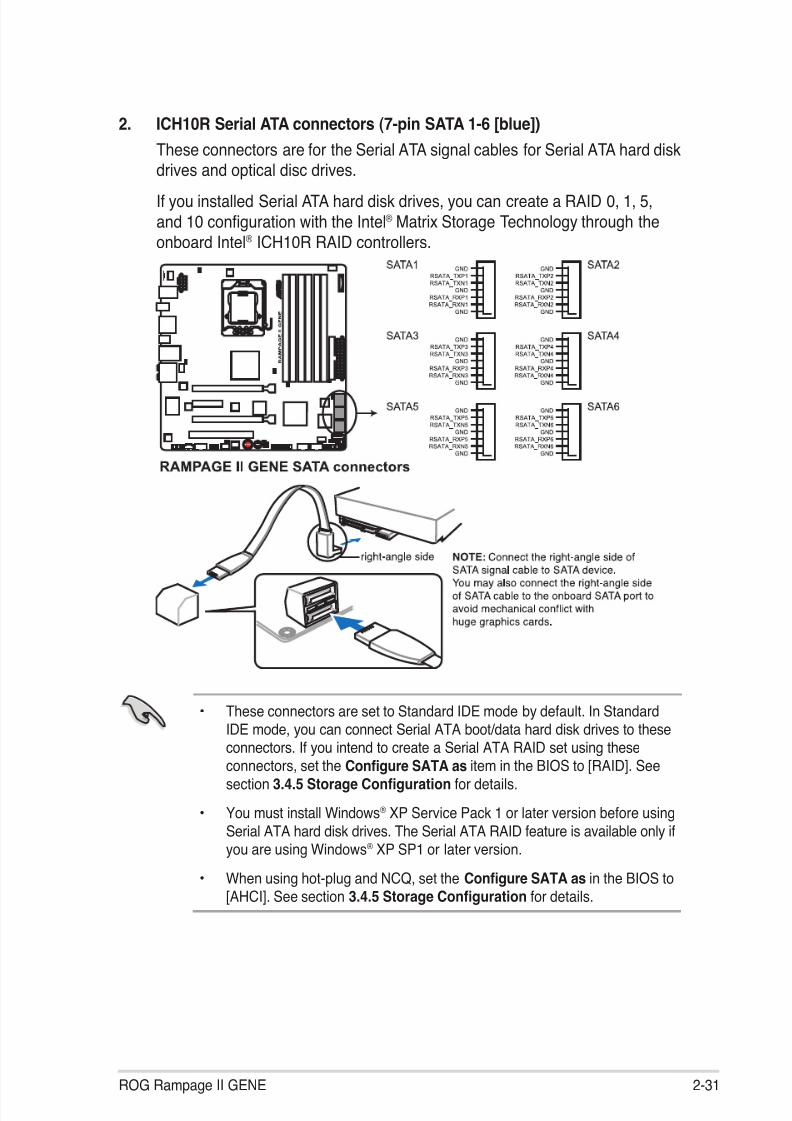
2. ICH10R Serial ATA connectors (7-pin SATA 1-6 [blue])These connectors are for the Serial ATA signal cables for Serial ATA hard diskdrives and optical disc drives.
If you installed Serial ATA hard disk drives, you can create a RAID 0, 1, 5,and 10 con guration with the Intel® Matrix Storage Technology through theonboard Intel ® ICH10R RAID controllers.
• These connectors are set to Standard IDE mode by default. In StandardIDE mode, you can connect Serial ATA boot/data hard disk drives to these
connectors. If you intend to create a Serial ATA RAID set using theseconnectors, set the Con gure SATA as item in the BIOS to [RAID]. Seesection 3.4.5 Storage Con guration for details.
• You must install Windows ® XP Service Pack 1 or later version before usingSerial ATA hard disk drives. The Serial ATA RAID feature is available only ifyou are using Windows ® XP SP1 or later version.
• When using hot-plug and NCQ, set the Con gure SATA as in the BIOS to[AHCI]. See section 3.4.5 Storage Con guration for details.
ROG Rampage II GENE 2-31

8/9/2019 Manual Placa Base Asus Rampage II Gene
http://slidepdf.com/reader/full/manual-placa-base-asus-rampage-ii-gene 56/176
4. USB connectors (10-1 pin USB78; USB910; USB1112)These connectors are for USB 2.0 ports. Connect the USB module cableto any of these connectors, then install the module to a slot opening at theback of the system chassis. These USB connectors comply with USB 2.0speci cation that supports up to 480 Mbps connection speed.
Never connect a 1394 cable to the USB connectors. Doing so will damage themotherboard!
You can connect the USB cable to ASUS Q-Connector (USB, blue) rst, andthen install the Q-Connector (USB) to the USB connector onboard.
3. JMicron JMB363 ® Serial ATA connector (7-pin SATA_E1 [black])This connector is for a Serial ATA signal cable for an external Serial ATA harddisk drive.
To enable hot-plugging, set the Controller Mode item in the BIOS settingto [AHCI], and then reboot the system. See section 3.5.3 Onboard DeviceCon guration for details.
2-32 Chapter 2: Hardware information

8/9/2019 Manual Placa Base Asus Rampage II Gene
http://slidepdf.com/reader/full/manual-placa-base-asus-rampage-ii-gene 57/176
5. IEEE 1394a port connector (10-1 pin IE1394_2)This connector is for an IEEE 1394a port. Connect the IEEE 1394a modulecable to this connector, then install the module to a slot opening at the backof the system chassis.
Never connect a USB cable to the IEEE 1394a connector. Doing so will damagethe motherboard!
6. Digital audio connector (4-1 pin SPDIF_OUT)This connector is for an additional Sony/Philips Digital Interface (S/PDIF)port(s). Connect the S/PDIF Out module cable to this connector, then installthe module to a slot opening at the back of the system chassis.
The S/PDIF module is purchased separately.
ROG Rampage II GENE 2-33

8/9/2019 Manual Placa Base Asus Rampage II Gene
http://slidepdf.com/reader/full/manual-placa-base-asus-rampage-ii-gene 58/176
8. Front panel audio connector (10-1 pin AAFP)This connector is for a chassis-mounted front panel audio I/O module thatsupports either HD Audio or legacy AC`97 audio standard. Connect one endof the front panel audio I/O module cable to this connector.
• We recommend that you connect a high-de nition front panel audiomodule to this connector to avail of the motherboard’s high-de nition audiocapability.
• If you want to connect a high-de nition front panel audio module to thisconnector, set the Front Panel Type item in the BIOS setup to [HD Audio];if you want to connect an AC'97 front panel audio module to this connector,set the item to [AC97]. By default, this connector is set to [HD Audio].
7. Optical drive audio connector (4-pin CD)These connectors allow you to receive stereo audio input from sound sourcessuch as a CD-ROM, TV tuner, or MPEG card.
2-34 Chapter 2: Hardware information

8/9/2019 Manual Placa Base Asus Rampage II Gene
http://slidepdf.com/reader/full/manual-placa-base-asus-rampage-ii-gene 59/176
9. CPU, chassis, and optional fan connectors(4-pin CPU_FAN, 3-pin CHA_FAN1–2, 3-pin OPT_FAN1–2)The fan connectors support cooling fans of 350 mA–2000 mA (24 W max.)or a total of 1 A–7 A (84 W max.) at +12V. Connect the fan cables to the fanconnectors on the motherboard, ensuring that the black wire of each cablematches the ground pin of the connector.
DO NOT forget to connect the fan cables to the fan connectors. Insuf cient airow inside the system may damage the motherboard components. These are
not jumpers! DO NOT place jumper caps on the fan connectors!
If you install two VGA cards, we recommend that you plug the chassis fancable to the motherboard connector labled OPT_FAN1/2 for better thermalenvironment.
ROG Rampage II GENE 2-35

8/9/2019 Manual Placa Base Asus Rampage II Gene
http://slidepdf.com/reader/full/manual-placa-base-asus-rampage-ii-gene 60/176
10. Thermal sensor cable connectors (2-pin OPT_TEMP1/2)These connectors are for temperature monitoring. Connect the thermalsensor cables to these connectors and place the other ends to the deviceswhich you want to monitor temperature. The optional fan1/2 can work withthe temperature sensors for a better cooling effect.
Enable OPT FAN1/2 overheat protection in BIOS if you connect thermalsensor cables to these connectors. Refer to page 3-34 for details.
11. Chassis intrusion connector (4-1 pin CHASSIS)This connector is for a chassis-mounted intrusion detection sensor or switch.Connect one end of the chassis intrusion sensor or switch cable to thisconnector. The chassis intrusion sensor or switch sends a high-level signal tothis connector when a chassis component is removed or replaced. The signalis then generated as a chassis intrusion event.
By default, the pin labeled “Chassis Signal” and “Ground” are shorted witha jumper cap. Remove the jumper caps only when you intend to use the
chassis intrusion detection feature.
2-36 Chapter 2: Hardware information
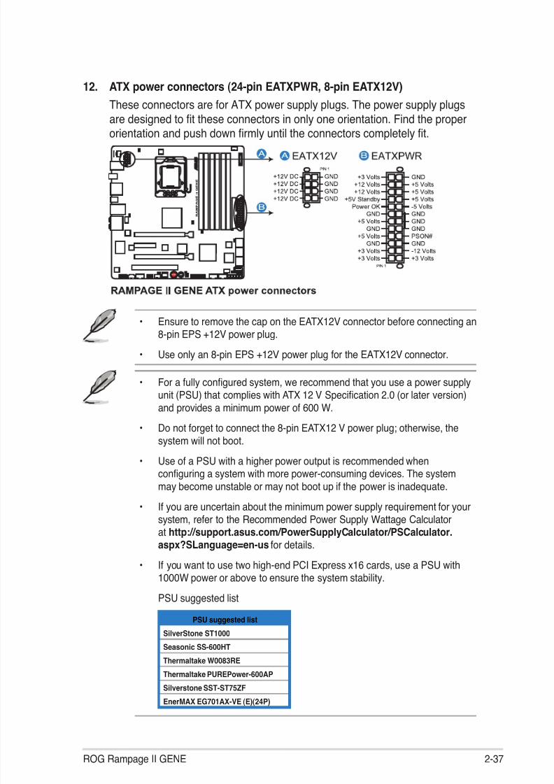
8/9/2019 Manual Placa Base Asus Rampage II Gene
http://slidepdf.com/reader/full/manual-placa-base-asus-rampage-ii-gene 61/176
12. ATX power connectors (24-pin EATXPWR, 8-pin EATX12V)These connectors are for ATX power supply plugs. The power supply plugsare designed to t these connectors in only one orientation. Find the properorientation and push down rmly until the connectors completely t.
• Ensure to remove the cap on the EATX12V connector before connecting an8-pin EPS +12V power plug.
• Use only an 8-pin EPS +12V power plug for the EATX12V connector.
• For a fully con gured system, we recommend that you use a power supplyunit (PSU) that complies with ATX 12 V Speci cation 2.0 (or later version)and provides a minimum power of 600 W.
• Do not forget to connect the 8-pin EATX12 V power plug; otherwise, thesystem will not boot.
• Use of a PSU with a higher power output is recommended whencon guring a system with more power-consuming devices. The systemmay become unstable or may not boot up if the power is inadequate.
• If you are uncertain about the minimum power supply requirement for your
system, refer to the Recommended Power Supply Wattage Calculatorat http://support.asus.com/PowerSupplyCalculator/PSCalculator.aspx?SLanguage=en-us for details.
• If you want to use two high-end PCI Express x16 cards, use a PSU with1000W power or above to ensure the system stability.
PSU suggested list
PSU suggested list
SilverStone ST1000
Seasonic SS-600HT
Thermaltake W0083RE
Thermaltake PUREPower-600AP
Silverstone SST-ST75ZF
EnerMAX EG701AX-VE (E)(24P)
ROG Rampage II GENE 2-37
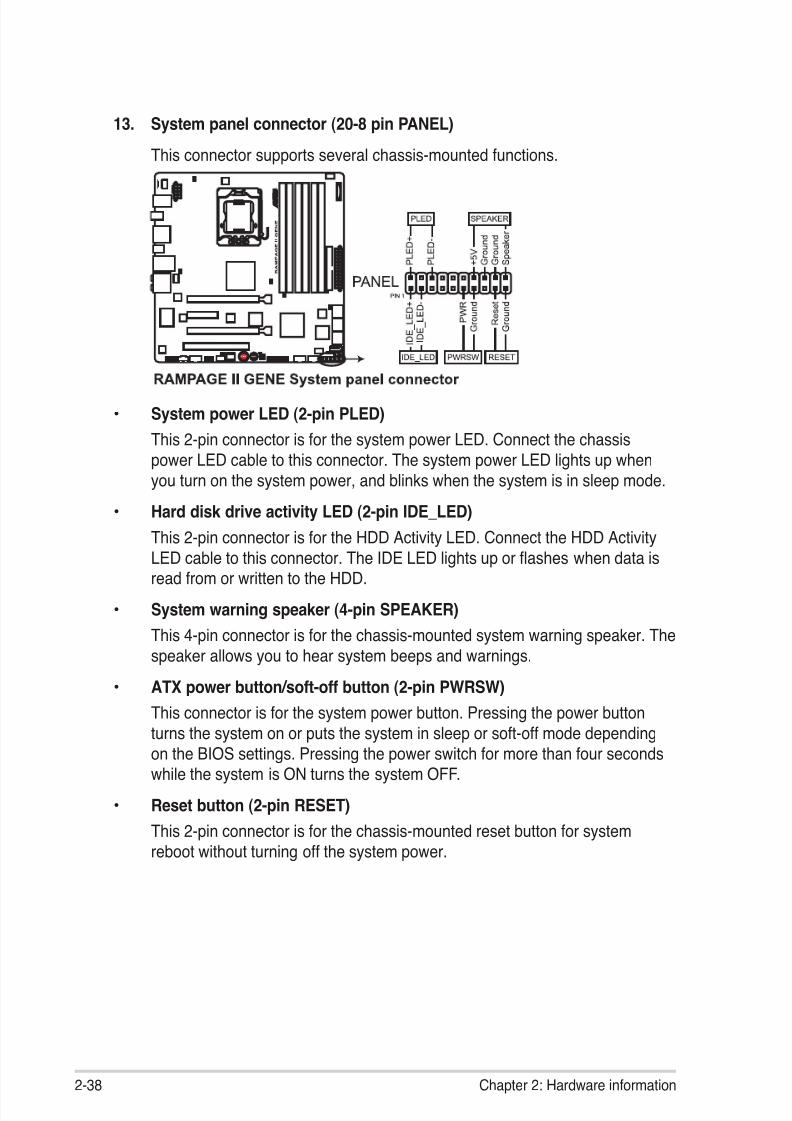
8/9/2019 Manual Placa Base Asus Rampage II Gene
http://slidepdf.com/reader/full/manual-placa-base-asus-rampage-ii-gene 62/176
• System power LED (2-pin PLED)This 2-pin connector is for the system power LED. Connect the chassispower LED cable to this connector. The system power LED lights up whenyou turn on the system power, and blinks when the system is in sleep mode.
• Hard disk drive activity LED (2-pin IDE_LED)This 2-pin connector is for the HDD Activity LED. Connect the HDD Activity
LED cable to this connector. The IDE LED lights up or ashes when data isread from or written to the HDD.• System warning speaker (4-pin SPEAKER)
This 4-pin connector is for the chassis-mounted system warning speaker. Thespeaker allows you to hear system beeps and warnings.
• ATX power button/soft-off button (2-pin PWRSW)This connector is for the system power button. Pressing the power buttonturns the system on or puts the system in sleep or soft-off mode dependingon the BIOS settings. Pressing the power switch for more than four secondswhile the system is ON turns the system OFF.
• Reset button (2-pin RESET)This 2-pin connector is for the chassis-mounted reset button for systemreboot without turning off the system power.
13. System panel connector (20-8 pin PANEL)
This connector supports several chassis-mounted functions.
2-38 Chapter 2: Hardware information

8/9/2019 Manual Placa Base Asus Rampage II Gene
http://slidepdf.com/reader/full/manual-placa-base-asus-rampage-ii-gene 63/176
ASUS Q-Connector (system panel)You can use the ASUS Q-Connector to connect/disconnect chassis front panelcables in a few steps. Refer to the instructions below to install the ASUSQ-Connector.
2. Install the ASUS Q-Connector to thesystem panel connector, ensuring theorientation matches the labels on the
motherboard.
3. The front panel functions are nowenabled. The gure shows theQ-Connector properly installed on themotherboard.
1. Connect the front panel cables to theASUS Q-Connector.Refer to the labels on the Q-Connectorto know the detailed pin de nitions, thenmatch them to the respective front panelcable labels.
The labels of the front panelcables may differ from chassismade by different manufacturers.
ROG Rampage II GENE 2-39

8/9/2019 Manual Placa Base Asus Rampage II Gene
http://slidepdf.com/reader/full/manual-placa-base-asus-rampage-ii-gene 64/176
2.7.3 Onboard switchesOnboard switches allow you to ne-tune performance when working on a bareor open-case system. This is ideal for overclockers and gamers who continually
change settings to enhance system performance.
1. Power-on switchPress the power-on switch to wake/power up the system.
2. Reset switchPress the reset switch to reboot the system.
2-40 Chapter 2: Hardware information

8/9/2019 Manual Placa Base Asus Rampage II Gene
http://slidepdf.com/reader/full/manual-placa-base-asus-rampage-ii-gene 65/176
3. MemOK! switch
Press the MemOK! switch to load failsafe settings for memory compatibilityand improving system boot success.
ROG Rampage II GENE 2-41

8/9/2019 Manual Placa Base Asus Rampage II Gene
http://slidepdf.com/reader/full/manual-placa-base-asus-rampage-ii-gene 66/176
2.7.4 Installing I/O shield and LCD Poster
2. Orient the motherboard and installit to the chassis. Ensure that the
motherboard external ports t theshield openings.
1. Install the I/O shield to thechassis by snaping it in place
from inside.
3. Thread the LCD Poster cablethrough the back I/O shieldopening until the stopper ts theopening.
4. Locate and connect the LCDPoster cable to the LCD_CON connector.
5. Place the LCD Poster on thechassis or to wherever you like.
2-42 Chapter 2: Hardware information

8/9/2019 Manual Placa Base Asus Rampage II Gene
http://slidepdf.com/reader/full/manual-placa-base-asus-rampage-ii-gene 67/176
2.8 Starting up for the rst time
1. After making all the connections, replace the system case cover.2. Be sure that all switches are off.
3. Connect the power cord to the power connector at the back of the systemchassis.
4. Connect the power cord to a power outlet that is equipped with a surgeprotector.
5. Turn on the devices in the following order: a. Monitor b. External SCSI devices (starting with the last device on the chain) c. System power6. After applying power, the system power LED on the system front panel case
lights up. For systems with ATX power supplies, the system LED lights upwhen you press the ATX power button. If your monitor complies with “green”standards or if it has a “power standby” feature, the monitor LED may light upor switch between orange and green after the system LED turns on.
The system then runs the power-on self tests or POST. While the tests arerunning, the BIOS beeps (see BIOS beep codes table below) or additionalmessages appear on the screen. If you do not see anything within 30seconds from the time you turned on the power, the system may have faileda power-on test. Check the jumper settings and connections or call yourretailer for assistance.
BIOS Beep Description
One short beep VGA detectedQuick boot set to disabledNo keyboard detected
One continuous beep followed by twoshort beeps then a pause (repeated)
No memory detected
One continuous beep followed by threeshort beeps
No VGA detected
One continuous beep followed by fourshort beeps
Hardware component failure
7. At power on, hold down the <Delete> key to enter the BIOS Setup. Follow theinstructions in Chapter 3.
ROG Rampage II GENE 2-43
8/9/2019 Manual Placa Base Asus Rampage II Gene
http://slidepdf.com/reader/full/manual-placa-base-asus-rampage-ii-gene 68/176
2.9 Turning off the computer
2.9.1 Using the OS shut down function
If you are using Windows ® Vista™:
1. Click the Start button then select Shut Down .2. The power supply should turn off after Windows ® shuts down.
If you are using Windows ® XP:
1. Click the Start button then select Turn Off Computer .2. Click the Turn Off button to shut down the computer.
3. The power supply should turn off after Windows ® shuts down.
2.9.2 Using the dual function power switch
While the system is ON, pressing the power switch for less than four seconds putsthe system to sleep mode or to soft-off mode, depending on the BIOS setting.Pressing the power switch for more than four seconds lets the system enter thesoft-off mode regardless of the BIOS setting. Refer to section 3.6 Power Menu inChapter 3 for details.
2-44 Chapter 2: Hardware information

8/9/2019 Manual Placa Base Asus Rampage II Gene
http://slidepdf.com/reader/full/manual-placa-base-asus-rampage-ii-gene 69/176
3BIOS setup
This chapter tells how to change thesystem settings through the BIOS Setupmenus. Detailed descriptions of the BIOSparameters are also provided.

8/9/2019 Manual Placa Base Asus Rampage II Gene
http://slidepdf.com/reader/full/manual-placa-base-asus-rampage-ii-gene 70/176
Chapter summary 3
ROG Rampage II GENE
3.1 Managing and updating your BIOS ............................................ 3- 13.2 BIOS setup program .................................................................... 3- 63.3 Extreme Tweaker menu ............................................................... 3- 93.4 Main menu .................................................................................. 3-183.5 Advanced menu ......................................................................... 3- 223.6 Power menu ................................................................................ 3- 30
3.7 Boot menu .................................................................................. 3- 353.8 Tools menu ................................................................................. 3- 393.9 Exit menu .................................................................................... 3- 43

8/9/2019 Manual Placa Base Asus Rampage II Gene
http://slidepdf.com/reader/full/manual-placa-base-asus-rampage-ii-gene 71/176

8/9/2019 Manual Placa Base Asus Rampage II Gene
http://slidepdf.com/reader/full/manual-placa-base-asus-rampage-ii-gene 72/176
3-2 Chapter 3: BIOS setup
Quit all Windows® applications before you update the BIOS using this utility.
3. Select the ASUS FTP site nearestyou to avoid network traf c, orclick Auto Select . Click Next .
Updating the BIOS through the InternetTo update the BIOS through the Internet:
1. Launch the ASUS Update utility from the Windows ® desktop by clicking Start> Programs > ASUS > ASUSUpdate > ASUSUpdate . The ASUS Updatemain window appears.
2. Select Update BIOS from theInternet option from the drop-downmenu, then click Next .

8/9/2019 Manual Placa Base Asus Rampage II Gene
http://slidepdf.com/reader/full/manual-placa-base-asus-rampage-ii-gene 73/176
ROG Rampage II GENE 3-3
Updating the BIOS through a BIOS leTo update the BIOS through a BIOS le:
1. Launch the ASUS Update utility from the Windows ® desktop by clicking Start > Programs > ASUS > ASUSUpdate > ASUSUpdate . The ASUS Updatemain window appears.
2. Select Update BIOS from a leoption from the drop-down menu,then click Next .
4. From the FTP site, select the BIOSversion that you wish to download.
Click Next .5. Follow the screen instructions to
complete the update process.
The ASUS Update utility iscapable of updating itself throughthe Internet. Always update theutility to avail all its features.
3. Locate the BIOS le from the Openwindow, then click Open .
4. Follow the screen instructions tocomplete the update process.
RAMIIGEN
RAMIIGEN.ROM

8/9/2019 Manual Placa Base Asus Rampage II Gene
http://slidepdf.com/reader/full/manual-placa-base-asus-rampage-ii-gene 74/176
3-4 Chapter 3: BIOS setup
3.1.2 ASUS EZ Flash 2 utilityThe ASUS EZ Flash 2 feature allows you to update the BIOS without having touse a DOS-based utility. The EZ Flash 2 utility is built in the BIOS chip so it is
accessible by pressing <Alt> + <F2> during the Power-On Self Tests (POST).
Before you start using this utility, download the latest BIOS from the ASUSwebsite at www.asus.com.
To update the BIOS using EZ Flash 21. Insert the USB ash disk that contains the latest BIOS le to the USB port,
and then launch EZ Flash 2 in any of these two ways:• Press <Alt> + <F2> during POST to display the following.• Enter the BIOS setup program. Go to the Tools menu to select EZ Flash
2 and press <Enter> to enable it.
ASUSTek EZ Flash 2 BIOS ROM Utility V3.34
Current ROM Update ROM
A:
Note [Enter] Select or Load [Tab] Switch [V] Drive Info
[Up/Down/Home/End] Move [B] Backup [Esc] Exit
FLASH TYPE: MXIC 25L1605A
PATH: A:\
BOARD: RampageII GENE VER: 0205
DATE: 01/13/2009
BOARD: Unknown VER: Unknown
DATE: Unknown
2. Press <Tab> to switch between drives until the correct BIOS le isfound. When found, EZ Flash 2 performs the BIOS update process andautomatically reboots the system when done.
• This function can support devices such as a USB ash disk with FAT 32/16format and single partition only.
• DO NOT shut down or reset the system while updating the BIOS to preventsystem boot failure!
Ensure to load the BIOS default settings to ensure system compatibility andstability. Select the Load Setup Defaults item under the Exit menu. Seesection 3.9 Exit Menu for details.

8/9/2019 Manual Placa Base Asus Rampage II Gene
http://slidepdf.com/reader/full/manual-placa-base-asus-rampage-ii-gene 75/176
ROG Rampage II GENE 3-5
3.1.3 ASUS CrashFree BIOS 3 utilityThe ASUS CrashFree BIOS 3 utility is an auto recovery tool that allows you torestore the BIOS le when it fails or gets corrupted during the updating process.
You can restore a corrupted BIOS le using the motherboard support DVD or aUSB ash drive that contains the BIOS le.
The BIOS le in the motherboard support DVD may be older than the BIOS lepublished on the ASUS of cial website. If you want to use the newer BIOS le,download the le at support.asus.com and save it to a USB ash drive.
Recovering the BIOS
To recover the BIOS1. Turn on the system.2. Insert the motherboard support DVD to the optical drive, or the USB ash
drive containing the BIOS le to the USB port.3. The utility automatically checks the devices for the BIOS le. When found,
the utility reads the BIOS le and starts ashing the corrupted BIOS le.4. Turn off the system after the utility completes the updating process and
power on again.5. The system requires you to enter BIOS Setup to recover BIOS setting. To
ensure system compatibility and stability, we recommend that you press<F2> to load default BIOS values.
DO NOT shut down or reset the system while recovering the BIOS! Doing socan cause system boot failure!

8/9/2019 Manual Placa Base Asus Rampage II Gene
http://slidepdf.com/reader/full/manual-placa-base-asus-rampage-ii-gene 76/176
3-6 Chapter 3: BIOS setup
3.2 BIOS setup programThis motherboard supports two programmable rmware chips that you can updateusing the provided utility described in section 3.1 Managing and updating yourBIOS.
Use the BIOS Setup program when you are installing a motherboard, recon guringyour system, or prompted to “Run Setup.” This section explains how to con gureyour system using this utility.
Even if you are not prompted to use the Setup program, you can change thecon guration of your computer in the future. For example, you can enable thesecurity password feature or change the power management settings. Thisrequires you to recon gure your system using the BIOS Setup program so that thecomputer can recognize these changes and record them in the CMOS RAM of the
rmware chip.
The rmware chip on the motherboard stores the Setup utility. When you start upthe computer, the system provides you with the opportunity to run this program.Press <Del> during the Power-On Self-Test (POST) to enter the Setup utility;otherwise, POST continues with its test routines.
If you wish to enter Setup after POST, restart the system by pressing<Ctrl+Alt+Delete>, or by pressing the reset button on the system chassis. You canalso restart by turning the system off and then back on. Do this last option only ifthe rst two failed.
The Setup program is designed to make it as easy to use as possible. Being amenu-driven program, it lets you scroll through the various sub-menus and makeyour selections from the available options using the navigation keys.
• The default BIOS settings for this motherboard apply for most conditionsto ensure optimum performance. If the system becomes unstable afterchanging any BIOS settings, load the default settings to ensure systemcompatibility and stability. Select the Load Setup Defaults item under theExit Menu. See section 3.9 Exit Menu .
• The BIOS setup screens shown in this section are for reference purposesonly, and may not exactly match what you see on your screen.
• Visit the ASUS website (www.asus.com) to download the latest BIOS le forthis motherboard.

8/9/2019 Manual Placa Base Asus Rampage II Gene
http://slidepdf.com/reader/full/manual-placa-base-asus-rampage-ii-gene 77/176
ROG Rampage II GENE 3-7
3.2.2 Menu barThe menu bar on top of the screen has the following main items:
Extreme Tweaker For changing the overclocking settingsMain For changing the basic system con gurationAdvanced For changing the advanced system settingsPower For changing the advanced power management (APM)
con gurationBoot For changing the system boot con gurationTools For Con guring options for special functionsExit For selecting the exit options and loading default settings
To select an item on the menu bar, press the right or left arrow key on thekeyboard until the desired item is highlighted.
3.2.3 Navigation keysAt the bottom right corner of a menu screen are the navigation keys for thatparticular menu. Use the navigation keys to select items in the menu and change
the settings.
3.2.1 BIOS menu screen
Some of the navigation keys differ from one screen to another.
v02.61 (C)Copyright 1985-2009, American Megatrends, Inc.
BIOS SETUP UTILITYExtreme Tweaker Main Advanced Power Boot Tools Exit
Use [ENTER], [TAB]or [SHIFT-TAB] toselect a feld.
Use [+] or [-] toconfgure system Date.
←→ Select Screen↑↓ Select Item +- Change Field Tab Select Field F1 General HelpF10 Save and ExitESC Exit
System Time [13:51:25]System Date [Wed 02/04/2009]Language [English]
SATA1 [HDT722516DLA380] SATA2 [Not Detected] SATA3 [ATAPI DVD D DH1] SATA4 [Not Detected] SATA5 [Not Detected] SATA6 [Not Detected]
Storage Con guration
System InformationSystem Information
Navigation keys
General helpMenu bar
Sub-menu items
Con guration eldsMenu items

8/9/2019 Manual Placa Base Asus Rampage II Gene
http://slidepdf.com/reader/full/manual-placa-base-asus-rampage-ii-gene 78/176
3-8 Chapter 3: BIOS setup
3.2.4 Menu itemsThe highlighted item on the menu bar displays the speci c items for that menu. Forexample, selecting Main shows the Main menu items.
The other items (Advanced, Power, Boot, and Exit) on the menu bar have theirrespective menu items.
3.2.5 Submenu itemsA solid triangle before each item on any menu screen means that the iteam has asubmenu. To display the submenu, select the item and press <Enter>.
3.2.6 Con guration elds
These elds show the values for the menu items. If an item is user-con gurable,you can change the value of the eld opposite the item. You cannot select an itemthat is not user-con gurable.
A con gurable eld is enclosed in brackets, and is highlighted when selected. Tochange the value of a eld, select it then press <Enter> to display a list of options.Refer to 3.2.7 Pop-up window.
3.2.7 Pop-up window
Select a menu item then press <Enter>to display a pop-up window with thecon guration options for that item.
3.2.8 Scroll barA scroll bar appears on the right sideof a menu screen when there are itemsthat do not t on the screen. Press theUp/Down arrow keys or <Page Up> /<Page Down> keys to display the otheritems on the screen.
3.2.9 General helpAt the top right corner of the menu screen is a brief description of the selecteditem.
v02.61 (C)Copyright 1985-2008, American Megatrends, Inc.
BIOS SETUP UTILITY Main Advanced Power Boot Tools Exit
Suspend Mode [Auto] ACPI Version Features [Disabled] ACPI APIC support [Enabled]
APM Con guration Hardware Monitor
←→ Select Screen↑↓ Select Item +- Change Field Tab Select Field F1 General HelpF10 Save and ExitESC Exit
Use [ENTER], [TAB] or[SHIFT-TAB] to selecta eld.
Use [+] or [-] tocon gure system Time.
Scroll bar
Disabled Enabled
Pop-up window

8/9/2019 Manual Placa Base Asus Rampage II Gene
http://slidepdf.com/reader/full/manual-placa-base-asus-rampage-ii-gene 79/176
ROG Rampage II GENE 3-9
3.3 Extreme Tweaker menuThe Extreme Tweaker menu items allow you to con gure overclocking-relateditems.
Take caution when changing the settings of the Extreme Tweaker menu items.Incorrect eld values can cause the system to malfunction.
The default values of the following items vary depending on the CPU andmemory modules you install on the motherboard.
v02.61 (C)Copyright 1985-2009, American Megatrends, Inc.
BIOS SETUP UTILITYExtreme Tweaker Main Advanced Power Boot Tools Exit
Tuning Mode is theBIOS menu switch fordifferent purpose.Extreme OC offersthe max tuning degreeof freedom to theextreme.Gaming provides the
major tuning settingsfor system
performance boot.
←→ Select Screen↑↓ Select Item +- Change Field F1 General HelpF10 Save and ExitESC Exit
Con gure System Performance Settings
Target CPU Frequency: 2660MHzTarget DRAM Frequency: 1066MHz
Tuning Mode [Extreme OC]CPU Level Up [Auto]
Memory Level Up [Auto] Ai Overclock Tuner [Auto]
Ratio Status:(Min:12, Max: 20)Ratio Actual Value:20CPU Ratio Setting [Auto]
CPU Con gurationDRAM Frequency [Auto]
DRAM Timing Control
EPU II Phase Control [Full Phase]CPU Load-Line Calibration [Auto]QPI Load-Line Calibration [Disabled]
v02.61 (C)Copyright 1985-2009, American Megatrends, Inc.
←→ Select Screen↑↓ Select Item +- Change OptionF1 General HelpF10 Save and ExitESC Exit
CPU Differential Amplitude [Auto] NB OCP [Enabled]
DRAM OCP [Enabled]*** Please key in numbers or select voltage! ***Extreme OV [Disabled]Current Voltage: 1.184V 1.819V 1.230V CPU Temperature: 43.5˚C/110˚FCPU Voltage [Auto]CPU PLL Voltage [Auto]QPI/DRAM Core Voltage [Auto]Current Voltage: 1.085V 1.508V 1.111V 1.508V
NB/SB Temperature: 45˚C/113˚F 52˚C/125.5˚F
IOH Voltage [Auto]IOH PCIE Voltage [Auto]ICH Voltage [Auto]ICH PCIE Voltage [Auto]Current Voltage: 1.508V DRAM Bus Voltage [Auto]
DRAM REF Voltages
Read POST Code from LCD Poster/iROG Control PlusDebug Mode [String]Keyboard TweakIt Control [Disabled]
******** Spread Spectrum and Clock Skew ********CPU Spread Spectrum [Auto]PCIE Spread Spectrum [Auto]CPU Clock Skew [Auto]
IOH Clock Skew [Auto]
Scroll down to display the following items:

8/9/2019 Manual Placa Base Asus Rampage II Gene
http://slidepdf.com/reader/full/manual-placa-base-asus-rampage-ii-gene 80/176
3-10 Chapter 3: BIOS setup
The following two items appear when you set Ai Overclock Tuner to [Manual].
3.3.4 Ai Overclock Tuner [Auto]Allows selection of CPU/memory overclocking options to achieve desired CPU/
memory internal frequency. Select any of the preset overclocking con guration options:Manual Allows you to individually set overclocking parameters.
Auto Loads the standard settings for the system.
X.M.P. Loads the optimal settings for the system.
CPU Level Up Allows you to select a CPU level, and the related parameterswill be adjusted automatically.
Memory Level Up Allows you to select a memory level, and the relatedparameters will be adjusted automatically.
ROG Memory Pro le Allows you to select a memory pro le, and the relatedparameters will be adjusted automatically.
Con gure System Performance Settings
The con guration options may vary depending on your CPU/memory model.
3.3.1 Tuning Mode [Extreme OC]The Tuning Mode item is the Extreme Tweaker menu item switch for differentpurpose. The Extreme OC mode offers the maximum tuning degree of freedomto the extreme. The Gaming mode provides the major tuning settings for systemperformance boost. Con guration options: [Extreme OC] [Gaming]
3.3.2 CPU Level Up [Auto]
Allows you to select a CPU level, and the related parameters will be automaticallyadjusted according to the selected CPU level. If you want to manually con gurethe settings in detail, set Ai Overclock Tuner to [Manual] after selecting a CPUlevel. Con guration options: [Auto] [i7-940-2.93G] [i7-965-3.20G] [i7-crazy-3.60G][i7-crazy-4.00G]
3.3.3 Memory Level Up [Auto]Allows you to select a memory level, and the related parameters will beautomatically adjusted according to the selected memory level. If you want to
manually con gure the settings in detail, setAi Overclock Tuner to [Manual] afterselecting a memory level.Con guration options: [Auto] [DDR3-1600MHz] [DDR3-1800MHz] [DDR3-2000MHz]
You are allowed to select either a CPU level or a memory level at one time.

8/9/2019 Manual Placa Base Asus Rampage II Gene
http://slidepdf.com/reader/full/manual-placa-base-asus-rampage-ii-gene 81/176
ROG Rampage II GENE 3-11
OC From CPU Level Up [Auto]After you select a CPU level and set Ai Overclock Tuner to [Manual], the relatedparameters will be adjusted accordingly.Con guration options: [Auto] [i7-940-2.93G] [i7-965-3.20G] [i7-crazy-3.60G][i7-crazy-4.00G]
OC From Memory Level Up [Auto]After you select a memory level and set Ai Overclock Tuner to [Manual], therelated parameters will be adjusted accordingly.Con guration options: [Auto] [DDR3-1600MHz] [DDR3-1800MHz] [DDR3-2000MHz][DDR3-2000MHz]
The following item appears only when you set Ai Overclock Tuner to [X.M.P].
eXtreme Memory Profile [Disabled] Allows you to select the memory pro le during overclocking between [Pro le#1] (high performance) and [Pro le #2] (high frequency). Con guration options: [Disabled] [Pro le #1] [Pro le #2]
The following item appears only when you set Ai Overclock Tuner to [ROGMemory Pro le].
R.O.G. Memory Profile [Speedy] Allows you to select the memory pro le mode supported by your memorymodule. Con guration options: [Speedy] [Flying] [Lightning]
3.3.5 CPU Ratio Setting [Auto]Allows you to adjust the ratio between CPU Core Clock and BCLK Frequency.Use the <+> and <-> keys to adjust the value. The valid value ranges differentlyThe valid value ranges differentlyaccording to your CPU model.
3.3.6 CPU Con gurationThe items in this menu show the CPU-related information that the BIOSautomatically detects. Refer to section 3.5.1 for details.
The following two items appear only when you set the Ai Overclock Tuner itemto [Manual] or [X.M.P.].
BCLK Frequency [XXX]Allows you to adjust the Internal Base Clock (BCLK). Use the <+> and <-> keys toadjust the value. You can also type the desired value using the numeric keypad.The values range from 100 to 500.

8/9/2019 Manual Placa Base Asus Rampage II Gene
http://slidepdf.com/reader/full/manual-placa-base-asus-rampage-ii-gene 82/176
3-12 Chapter 3: BIOS setup
PCIE Frequency [XXX]Allows you to set the PCI Express frequency. Use the <+> and <-> keys to adjustthe PCIE frequency. You can also type the desired value using the numerickeypad. The values range from 100 to 200.
3.3.7 DRAM Frequency [Auto]Allows you to set the DDR3 operating frequency.Con guration options: [Auto] [DDR3-800MHz] [DDR3-1066MHz] [DDR3-1333MHz][DDR3-1600MHz] [DDR3-1866MHz] [DDR3-2133MHz]
The DRAM Frequency con guration options vary with theBCLK Frequency item settings.
A very high DRAM frequency may cause the system to become unstable! If thishappens, revert to the default setting.
3.3.8 DRAM Timing ControlThe items in this menu allow you to set the DRAM timing control features.
The con guration options for some of the following items vary depending on theDIMMs you install on the motherboard.
1st Information: 6-6-6-15-4-36-6-3-16-4 (These values are auto-detected)(These values are auto-detected)DRAM CAS# Latency [Auto]Con guration options: [Auto] [3 DRAM Clock] – [11 DRAM Clock]
DRAM RAS# to CAS# Delay [Auto]Con guration options: [Auto] [3 DRAM Clock] – [10 DRAM Clock]
DRAM RAS# PRE Time [Auto]
Con guration options: [Auto] [3 DRAM Clock] – [10 DRAM Clock]DRAM RAS# ACT Time [Auto]Con guration options: [Auto] [3 DRAM Clock] – [31 DRAM Clock]
DRAM RAS# to RAS# Delay [Auto]Con guration options: [Auto] [1 DRAM Clock] – [7 DRAM Clock]
DRAM REF Cycle Time [Auto]Con guration options: [Auto] [30 DRAM Clock] [36 DRAM Clock] [48 DRAM Clock] [60 DRAM Clock] [72 DRAM Clock] [82 DRAM Clock][88 DRAM Clock] [90 DRAM Clock] [100 DRAM Clock] [110 DRAM Clock]
DRAM WRITE Recovery Time [Auto]Con guration options: [Auto] [1 DRAM Clock] – [15 DRAM Clock]
DRAM READ to PRE Time [Auto]Con guration options: [Auto] [3 DRAM Clock] – [15 DRAM Clock]
8/9/2019 Manual Placa Base Asus Rampage II Gene
http://slidepdf.com/reader/full/manual-placa-base-asus-rampage-ii-gene 83/176
ROG Rampage II GENE 3-13
DRAM FOUR ACT WIN Time [Auto]Con guration options: [Auto] [1 DRAM Clock] – [63 DRAM Clock]
DRAM Back-To-Back CAS# Delay [Auto]Con guration options: [Auto] [4 DRAM Clock] – [32 DRAM Clock]
2nd Information: 1N-66-0-0 (These values are auto-detected)(These values are auto-detected)DRAM Timing Mode [Auto]Con guration options: [Auto] [1N] [2N] [3N]
DRAM Round Trip Latency on CHA/B/C [Auto][Auto] [Advance 15 Clock]–[Advance 1 Clock] [Normal][Delay 1 Clock]–[Delay 15 Clock] –[Delay 15 Clock][Delay 15 Clock]
3rd Information: 6-6-13-9-9-9-7-6-4-7-7-4 (These values are auto-detected)(These values are auto-detected)DRAM WRITE to READ Delay(DD) [Auto]Con guration options: [Auto] [1 DRAM Clock] – [8 DRAM Clock]
DRAM WRITE to READ Delay(DR) [Auto]Con guration options: [Auto] [1 DRAM Clock] – [8 DRAM Clock]
DRAM WRITE to READ Delay(SR) [Auto]Con guration options: [Auto] [10 DRAM Clock] – [22 DRAM Clock]
DRAM READ to WRITE Delay(DD) [Auto]Con guration options: [Auto] [2 DRAM Clock] – [14 DRAM Clock]
DRAM READ to WRITE Delay(DR) [Auto]Con guration options: [Auto] [2 DRAM Clock] – [14 DRAM Clock]
DRAM READ to WRITE Delay(SR) [Auto]Con guration options: [Auto] [2 DRAM Clock] – [14 DRAM Clock]
DRAM READ to READ Delay(DD) [Auto]Con guration options: [Auto] [2 DRAM Clock] – [9 DRAM Clock]
DRAM READ to READ Delay(DR) [Auto]Con guration options: [Auto] [2 DRAM Clock] – [9 DRAM Clock]
DRAM READ to READ Delay(SR) [Auto]Con guration options: [Auto] [4 DRAM Clock] [6 DRAM Clock]
DRAM WRITE to WRITE Delay(DD) [Auto]Con guration options: [Auto] [2 DRAM Clock] – [9 DRAM Clock]
DRAM WRITE to WRITE Delay(DR) [Auto]Con guration options: [Auto] [2 DRAM Clock] – [9 DRAM Clock]
DRAM WRITE to WRITE Delay(SR) [Auto]Con guration options: [Auto] [4 DRAM Clock] [6 DRAM Clock]
3.3.9 EPU II Phase Control [Full Phase]Con guration options: [Auto] [Normal] [Full Phase]
8/9/2019 Manual Placa Base Asus Rampage II Gene
http://slidepdf.com/reader/full/manual-placa-base-asus-rampage-ii-gene 84/176

8/9/2019 Manual Placa Base Asus Rampage II Gene
http://slidepdf.com/reader/full/manual-placa-base-asus-rampage-ii-gene 85/176
ROG Rampage II GENE 3-15
Refer to the CPU documentation before setting the CPU VCore voltage. Settinga high voltage may damage the CPU permanently, and setting a low voltagemay make the system unstable.
3.3.17 CPU PLL Voltage [Auto]Allows you to select the CPU PLL voltage. The text color in the con guration
eld corresponds to the onboard CPU LED color, both of which indicate voltagecondition. When you set the CPU LED Selection item to [CPU PLL], the onboardCPU LED displays CPU PLL voltage condition. Refer to page 2-2 for CPU LEDde nition. The values range from 1.81592V to 2.50492V with a 0.01325V interval.
3.3.18 QPI/DRAM Core Voltage [Auto]Allows you to select the QPI/DRAM Core voltage. The text color in thecon guration eld corresponds to the onboard CPU LED color, both of whichindicate voltage condition. When you set the CPU LED Selection item to [QPI/ DRAM Core], the onboard CPU LED displays QPI/DRAM Core voltage condition.Refer to page 2-2 for CPU LED de nition. The values range from 1.20000V to2.50000V with a 0.00625V interval.
The QPI/DRAM Core voltage could be set only up to 1.8V when the ExtremeOV item is set to [Disabled].
3.3.19 IOH Voltage [Auto]Allows you to set the I/O Hub (IOH) voltage. The values range from 1.11341V to2.19991V with a 0.01325V interval.
3.3.20 IOH PCIE Voltage [Auto]Allows you to set the IOH PCIE voltage. The values range from 1.51106V to2.78306V with a 0.01325V interval.
3.3.21 ICH Voltage [Auto]Allows you to set the I/O Controller Hub (ICH) voltage. The values range from1.11341V to 2.00116V with a 0.01325V interval.
3.3.22 ICH PCIE Voltage [Auto]Allows you to set the ICH PCIE voltage. The values range from 1.51106V to2.05431V with a 0.01325V interval.
3.3.23 DRAM Bus Voltage [Auto]Allows you to set the DRAM voltage. The values range from 1.51106V to 2.50481Vwith a 0.01325V interval.
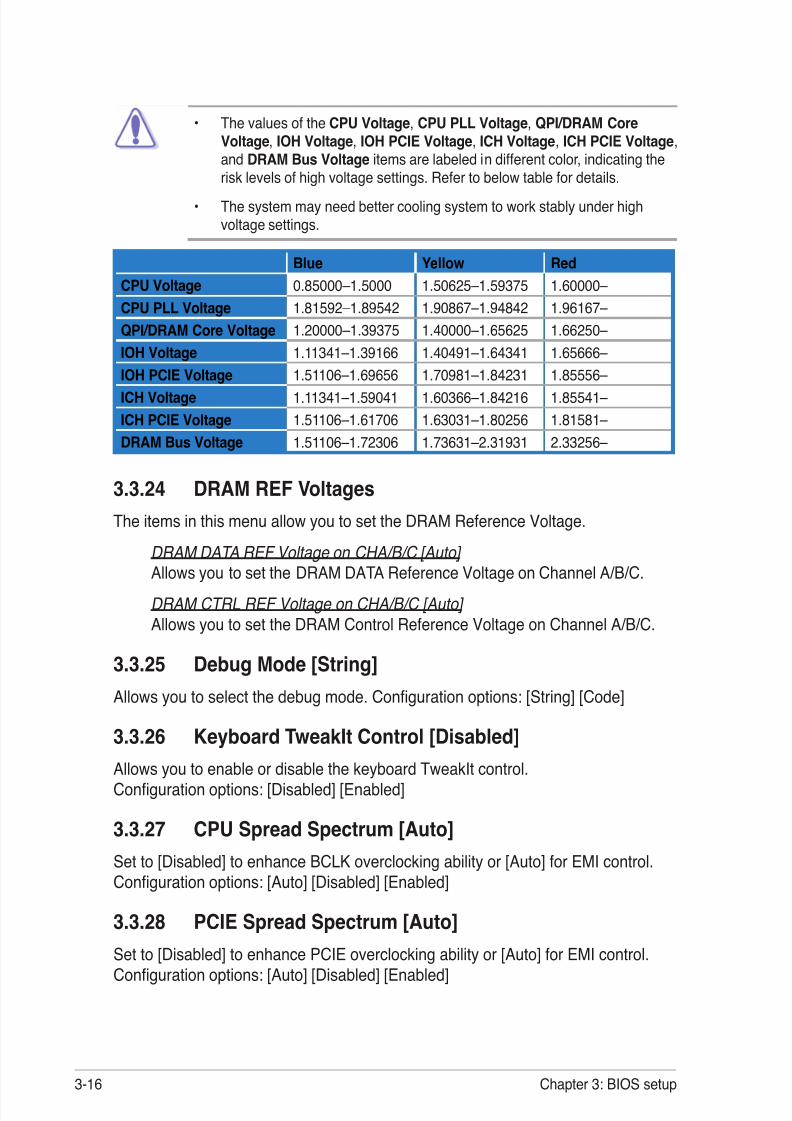
8/9/2019 Manual Placa Base Asus Rampage II Gene
http://slidepdf.com/reader/full/manual-placa-base-asus-rampage-ii-gene 86/176
3-16 Chapter 3: BIOS setup
• The values of the CPU Voltage , CPU PLL Voltage , QPI/DRAM CoreVoltage , IOH Voltage , IOH PCIE Voltage , ICH Voltage , ICH PCIE Voltage ,and DRAM Bus Voltage items are labeled in different color, indicating therisk levels of high voltage settings. Refer to below table for details.
• The system may need better cooling system to work stably under highvoltage settings.
Blue Yellow RedCPU Voltage 0.85000–1.5000 1.50625–1.59375 1.60000–CPU PLL Voltage 1.81592–1.89542 1.90867–1.94842 1.96167–QPI/DRAM Core Voltage 1.20000–1.39375 1.40000–1.65625 1.66250–IOH Voltage 1.11341–1.39166 1.40491–1.64341 1.65666–
IOH PCIE Voltage 1.51106–1.69656 1.70981–1.84231 1.85556–ICH Voltage 1.11341–1.59041 1.60366–1.84216 1.85541–ICH PCIE Voltage 1.51106–1.61706 1.63031–1.80256 1.81581–DRAM Bus Voltage 1.51106–1.72306 1.73631–2.31931 2.33256–
3.3.24 DRAM REF VoltagesThe items in this menu allow you to set the DRAM Reference Voltage.
DRAM DATA REF Voltage on CHA/B/C [Auto] Allows you to set the DRAM DATA Reference Voltage on Channel A/B/C.
DRAM CTRL REF Voltage on CHA/B/C [Auto] Allows you to set the DRAM Control Reference Voltage on Channel A/B/C.
3.3.25 Debug Mode [String]Allows you to select the debug mode. Con guration options: [String] [Code]
3.3.26 Keyboard TweakIt Control [Disabled]Allows you to enable or disable the keyboard TweakIt control.Con guration options: [Disabled] [Enabled]
3.3.27 CPU Spread Spectrum [Auto]Set to [Disabled] to enhance BCLK overclocking ability or [Auto] for EMI control.Con guration options: [Auto] [Disabled] [Enabled]
3.3.28 PCIE Spread Spectrum [Auto]Set to [Disabled] to enhance PCIE overclocking ability or [Auto] for EMI control.Con guration options: [Auto] [Disabled] [Enabled]

8/9/2019 Manual Placa Base Asus Rampage II Gene
http://slidepdf.com/reader/full/manual-placa-base-asus-rampage-ii-gene 87/176
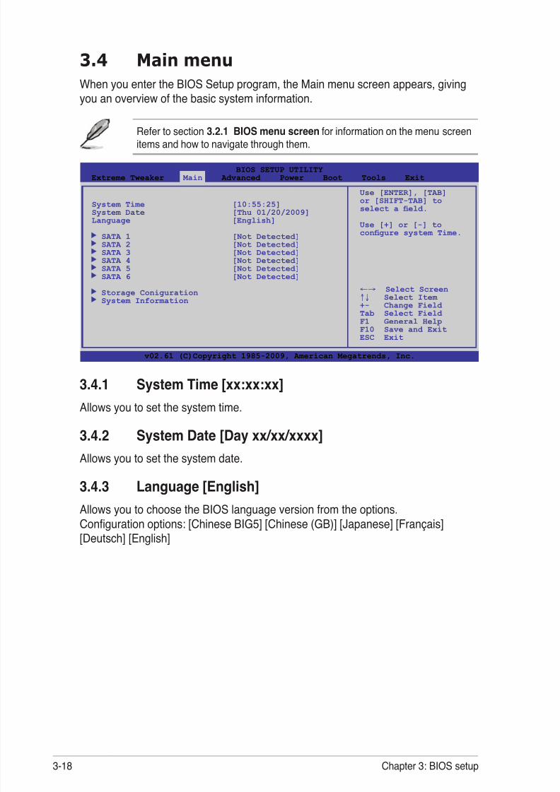
8/9/2019 Manual Placa Base Asus Rampage II Gene
http://slidepdf.com/reader/full/manual-placa-base-asus-rampage-ii-gene 88/176
3-18 Chapter 3: BIOS setup
3.4 Main menuWhen you enter the BIOS Setup program, the Main menu screen appears, givingyou an overview of the basic system information.
3.4.1 System Time [xx:xx:xx]Allows you to set the system time.
3.4.2 System Date [Day xx/xx/xxxx]Allows you to set the system date.
3.4.3 Language [English]Allows you to choose the BIOS language version from the options.
Con guration options: [Chinese BIG5] [Chinese (GB)] [Japanese] [Français][Deutsch] [English]
Refer to section 3.2.1 BIOS menu screen for information on the menu screenitems and how to navigate through them.
v02.61 (C)Copyright 1985-2009, American Megatrends, Inc.
BIOS SETUP UTILITYExtreme Tweaker Main Advanced Power Boot Tools Exit
Use [ENTER], [TAB]or [SHIFT-TAB] toselect a eld.
Use [+] or [-] tocon gure system Time.
←→ Select Screen↑↓ Select Item +- Change Field Tab Select Field F1 General HelpF10 Save and ExitESC Exit
System Time [10:55:25]System Date [Thu 01/20/2009]Language [English]
SATA 1 [Not Detected] SATA 2 [Not Detected] SATA 3 [Not Detected]
SATA 4 [Not Detected] SATA 5 [Not Detected] SATA 6 [Not Detected]
Storage Coniguration System Information

8/9/2019 Manual Placa Base Asus Rampage II Gene
http://slidepdf.com/reader/full/manual-placa-base-asus-rampage-ii-gene 89/176
ROG Rampage II GENE 3-19
3.4.4 SATA 1–6While entering Setup, the BIOS automatically detects the presence of Serial ATAdevices. There is a separate sub-menu for each SATA device. Select a device item
then press <Enter> to display the SATA device information.
The BIOS automatically detects the values opposite the dimmed items (Device,Vendor, Size, LBA Mode, Block Mode, PIO Mode, Async DMA, Ultra DMA, andSMART monitoring). These values are not user-con gurable. These items show[Auto] if no IDE device is installed in the system.
Type [Auto]Selects the type of SATA drive. Setting to [Auto] allows automatic selection of theappropriate SATA device type. Select [CDROM] if you are speci cally con guring aCD-ROM drive. Select [ARMD] (ATAPI Removable Media Device) if your device iseither a ZIP, LS-120, or MO drive.Con guration options: [Not Installed] [Auto] [CDROM] [ARMD]
LBA/Large Mode [Auto]Enables or disables the LBA mode. Setting to [Auto] enables the LBA mode if thedevice supports this mode, and if the device was not previously formatted with LBAmode disabled. Con guration options: [Disabled] [Auto]
Block (Multi-sector Transfer) M [Auto]Enables or disables data multi-sectors transfers. When set to [Auto], the datatransfer from and to the device occurs multiple sectors at a time if the devicesupports multi-sector transfer feature. When set to [Disabled], the data transferfrom and to the device occurs one sector at a time.Con guration options: [Disabled] [Auto]
PIO Mode [Auto]Selects the PIO mode. Con guration options: [Auto] [0] [1] [2] [3] [4]
v02.61 (C)Copyright 1985-2009, American Megatrends, Inc.
BIOS SETUP UTILITY Main
Select the typeof device connectedto the system.
←→ Select Screen↑↓ Select Item +- Change Field F1 General HelpF10 Save and ExitESC Exit
SATA 1Device :Hard Disk
Vendor :HDT722516DLA380Size :164.7GBLBA Mode :Supported Block Mode:16SectorsPIO Mode :4
Async DMA :MultiWord DMA-2Ultra DMA :Ultra DMA-5SMART Monitoring:Supported Type [Auto]LBA/Large Mode [Auto]Block(Multi-Sector Transfer)M [Auto]PIO Mode [Auto]DMA Mode [Auto]SMART Monitoring [Auto]32Bit Data Transfer [Enabled]

8/9/2019 Manual Placa Base Asus Rampage II Gene
http://slidepdf.com/reader/full/manual-placa-base-asus-rampage-ii-gene 90/176
3-20 Chapter 3: BIOS setup
DMA Mode [Auto]Selects the DMA mode. Con guration options: [Auto]
SMART Monitoring [Auto]Sets the Smart Monitoring, Analysis, and Reporting Technology.Con guration options: [Auto] [Disabled] [Enabled]
32Bit Data Transfer [Enabled]Enables or disables 32-bit data transfer.Con guration options: [Disabled] [Enabled]
SATA Con guration [Enhanced]Con guration options: [Disabled] [Compatible] [Enhanced]
Configure SATA as [IDE] Sets the con guration for the Serial ATA connectors supported by theSouthbridge chip.
If you want to use the Serial ATA hard disk drives as Parallel ATA physicalstorage devices, keep the defaul setting [IDE].
If you want the Serial ATA hard disk drives to use the Advanced HostController Interface (AHCI), set this item to [AHCI]. The AHCI allows theonboard storage driver to enable advanced Serial ATA features that increasesstorage performance on random workloads by allowing the drive to internallyoptimize the order of commands.
If you want to create a RAID 0, RAID 1, RAID 5, RAID 10, or the Intel® MatrixStorage Technology con guration from the Serial ATA hard disk drives, setthis item to [RAID].
3.4.5 Storage Con gurationThe items in this menu allow you to set or change the con gurations for the SATAdevices installed in the system. Select an item then press <Enter> if you want tocon gure the item.
BIOS SETUP UTILITY Main
Storage Con guration
SATA Con guraton [Enhanced] Con gure SATA as [IDE]
Hard Disk Write Protect [Disabled]
IDE Detect Time Out (Sec) [35]
Set [Compatible Mode] when Legacy OS (i.e. WIN ME, 98, NT4.0, MS
DOS) is used.
Set [Enhanced Mode]
when Native OS (i.e. WIN2000, Win XP, Vistais used.
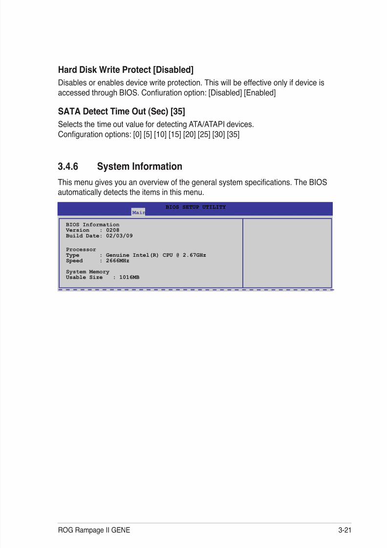
8/9/2019 Manual Placa Base Asus Rampage II Gene
http://slidepdf.com/reader/full/manual-placa-base-asus-rampage-ii-gene 91/176
ROG Rampage II GENE 3-21
Hard Disk Write Protect [Disabled]Disables or enables device write protection. This will be effective only if device is
accessed through BIOS. Con uration option: [Disabled] [Enabled]
SATA Detect Time Out (Sec) [35]Selects the time out value for detecting ATA/ATAPI devices.Con guration options: [0] [5] [10] [15] [20] [25] [30] [35]
3.4.6 System Information
This menu gives you an overview of the general system speci cations. The BIOSautomatically detects the items in this menu.
BIOS SETUP UTILITY Main
BIOS Information Version : 0208
Build Date: 02/03/09
ProcessorType : Genuine Intel(R) CPU @ 2.67GHzSpeed : 2666MHz
System MemoryUsable Size : 1016MB
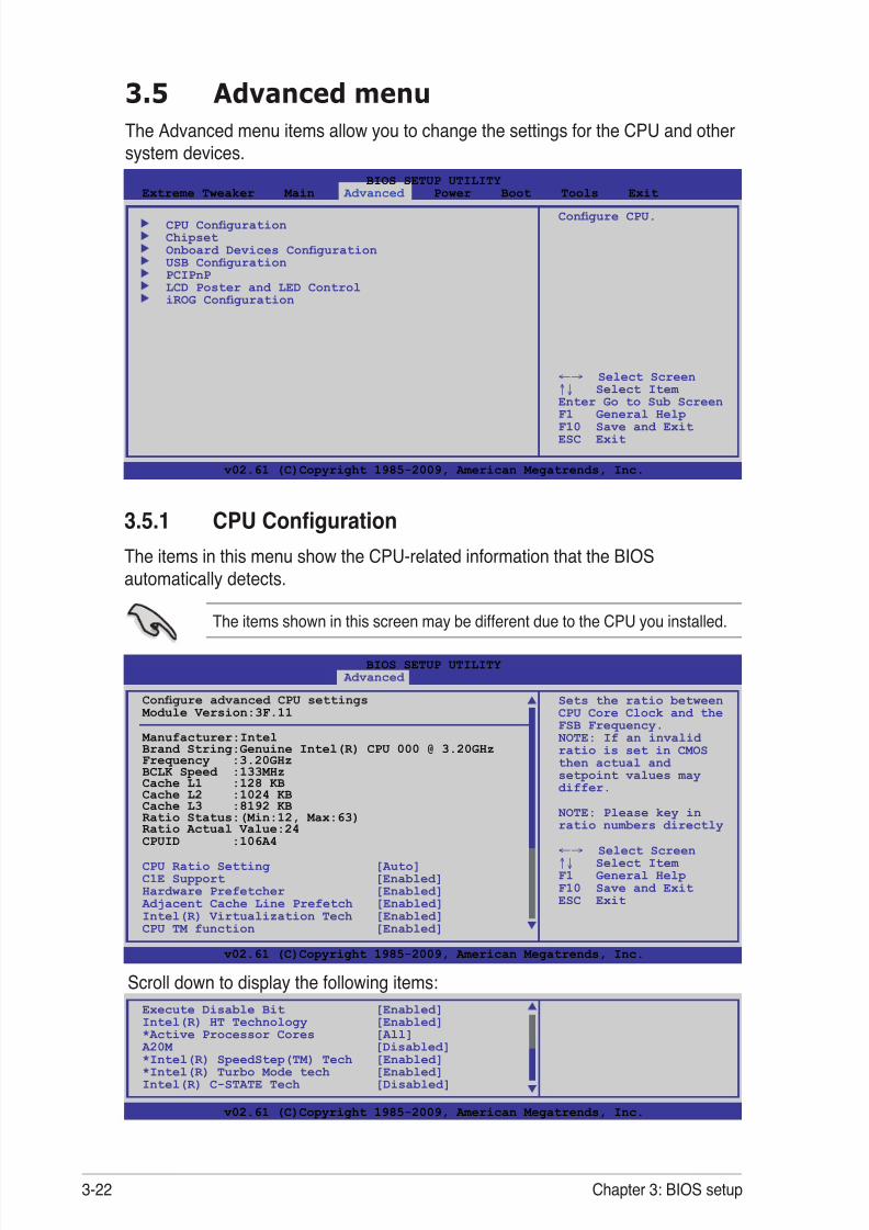
8/9/2019 Manual Placa Base Asus Rampage II Gene
http://slidepdf.com/reader/full/manual-placa-base-asus-rampage-ii-gene 92/176
3-22 Chapter 3: BIOS setup
3.5 Advanced menuThe Advanced menu items allow you to change the settings for the CPU and othersystem devices.
3.5.1 CPU Con gurationThe items in this menu show the CPU-related information that the BIOSautomatically detects.
The items shown in this screen may be different due to the CPU you installed.
v02.61 (C)Copyright 1985-2009, American Megatrends, Inc.
BIOS SETUP UTILITYExtreme Tweaker Main Advanced Power Boot Tools Exit
Con gure CPU.
←→ Select Screen↑↓ Select Item Enter Go to Sub ScreenF1 General HelpF10 Save and ExitESC Exit
CPU Con guration Chipset Onboard Devices Con guration USB Con guration PCIPnP LCD Poster and LED Control iROG Con guration
v02.61 (C)Copyright 1985-2009, American Megatrends, Inc.
BIOS SETUP UTILITY Advanced
Sets the ratio betweenCPU Core Clock and theFSB Frequency.
NOTE: If an invalidratio is set in CMOSthen actual andsetpoint values maydiffer.
NOTE: Please key inratio numbers directly
←→ Select Screen↑↓ Select Item F1 General HelpF10 Save and ExitESC Exit
Con gure advanced CPU settings Module Version:3F.11
Manufacturer:IntelBrand String:Genuine Intel(R) CPU 000 @ 3.20GHzFrequency :3.20GHzBCLK Speed :133MHzCache L1 :128 KBCache L2 :1024 KBCache L3 :8192 KB
Ratio Status:(Min:12, Max:63)Ratio Actual Value:24CPUID :106A4
CPU Ratio Setting [Auto]C1E Support [Enabled]Hardware Prefetcher [Enabled]
Adjacent Cache Line Prefetch [Enabled]Intel(R) Virtualization Tech [Enabled]CPU TM function [Enabled]
v02.61 (C)Copyright 1985-2009, American Megatrends, Inc.
Execute Disable Bit [Enabled]
Intel(R) HT Technology [Enabled]*Active Processor Cores [All] A20M [Disabled]
*Intel(R) SpeedStep(TM) Tech [Enabled]*Intel(R) Turbo Mode tech [Enabled]Intel(R) C-STATE Tech [Disabled]
Scroll down to display the following items:

8/9/2019 Manual Placa Base Asus Rampage II Gene
http://slidepdf.com/reader/full/manual-placa-base-asus-rampage-ii-gene 93/176
ROG Rampage II GENE 3-23
CPU Ratio Setting [Auto]Allows you to adjust the ratio between CPU Core Clock and BCLK Frequency.Use the <+> and <-> keys to adjust the value. The valid value ranges differentlyaccording to your CPU model.
C1E Support [Enabled]Allows you to enable or disable Enhanced Halt State support.Con guration options: [Disabled] [Enabled]
Hardware Prefetcher [Enabled]Allows you to enable or disable the Hardware Prefetcher function.Con guration options: [Disabled] [Enabled]
Adjacent Cache Line Prefetch [Enabled]Allows you to enable or disable the Adjacent Cache Line Prefetch function.Con guration options: [Disabled] [Enabled]
Intel(R) Virtualization Tech [Enabled]The Intel® Virtualization Technology allows a hardware platform to run multipleoperating systems separately and simultaneously, enabling one system to virtuallyfunction as several systems. Con guration options: [Disabled] [Enabled]
CPU TM Function [Enabled]This function enables the overheated CPU to throttle the clock speed to cool down.Con guration options: [Disabled] [Enabled]
Execute Disable Bit [Enabled]Allows you to enable or disable the No-Execution Page Protection Technology.Setting this item to [Disabled] forces the XD feature ag to always return to zero (0).Con guration options: [Disabled] [Enabled]
Intel(R) HT Technology [Enabled]Allows you to enable or disable the Intel Hyper-Threading Technology function.When disabled, only one thread per activated core is enabled.Con guration options: [Enabled] [Disabled]
*Active Processor Cores [All]Allows you to choose the number of CPU cores to activate in each processorpackage. Con guration options: [All] [1] [2]
A20M [Disabled]Legacy OSes and APs may need A20M enabled.Con guration options: [Disabled] [Enabled]

8/9/2019 Manual Placa Base Asus Rampage II Gene
http://slidepdf.com/reader/full/manual-placa-base-asus-rampage-ii-gene 94/176
3-24 Chapter 3: BIOS setup
*Intel(R) SpeedStep(TM) Tech [Enabled]When set to [Disabled], the CPU runs at its default speed. When set to [Enabled],the CPU speed is controlled by the operating system.Con guration options: [Disabled] [Enabled]
*Intel(R) TurboMode tech [Enabled]Turbo mode allows processor cores to run faster than marked frequency in speci ccondition. Con guration options: [Disabled] [Enabled]
Intel(R) C-STATE Tech [Disabled]Allows you enable or disable the Intel ® C-STATE Technology. When enabled, theCPU idle is set to C2/C3/C4. Con guration options: [Disabled] [Enabled]
The following item appears only when you set Intel(R) C-STATE Tech to
[Enabled].
C State package limit setting [Auto]Allows you to select the C State package limit setting.Con guration options: [Auto] [C1] [C3] [C6] [C7]
3.5.2 ChipsetThe Chipset menu allows you to change the advanced chipset settings. Select anitem then press <Enter> to display the sub-menu.
Intel VT-d Con guration
Intel VT-d [Disabled] Allows you to enable or disable the Intel Virtualization Technology forDirected I/O. Con guration options: [Disabled] [Enabled]
BIOS SETUP UTILITY Advanced
Advanced Chipset Settings
WARMING: Setting wrong values in below sections may cause system to malfunction.
Intel VT-d Con guration
BIOS SETUP UTILITY Advanced
Intel VT-d Con guration
Intel VT-d [Disabled]Intel VirtualizationTechnology forDirected I/O.

8/9/2019 Manual Placa Base Asus Rampage II Gene
http://slidepdf.com/reader/full/manual-placa-base-asus-rampage-ii-gene 95/176
ROG Rampage II GENE 3-25
3.5.3 Onboard Device Con guration
Onboard Device [Standard]
Allows you to disable all the onboard device controllers except the LAN controller.Con guration options: [Standard] [Disabled]
High De nition Audio [Enabled]Allows you to enable or disable the High De nition Audio Controller. Con guration options: [Enabled] [Disabled]
Front Panel Type [HD Audio] Allows you to set the front panel audio connector (AAFP) mode to legacyAC’97 or high-de nition audio depending on the audio standard that the frontpanel audio module supports. Con guration options: [AC97] [HD Audio]
J-Micron eSATA/PATA Controller [Enabled]Allows you to enable or disable the onboard JMicron eSATA/PATA controller.Con guration options: [Enabled] [Disabled]
Controller Mode [IDE] This item appears only when you enable the previous item.Con guration options: [IDE] [AHCI]
If you want to use the hard disk drive as a Parallel ATA physical storagedevice, keep the defaul setting [IDE].
If you want the hard disk drive to use the Advanced Host Controller Interface(AHCI), set this item to [AHCI].
Realtek LAN [Enabled]Allows you to enable or disable the onboard LAN controller.Con guration options: [Enabled] [Disabled]
Onboard LAN Boot ROM [Disabled] This item appears only when you enable the previous item.Con guration options: [Disabled] [Enabled]
BIOS SETUP UTILITY Advanced
Onboard Device Con guration
Onboard Device [Standard]
High De nition Audio [Enabled] Front Panel Type [HD Audio]
J-Micron eSATA/PATA Controller [Enabled] Controller Mode [IDE]Realtek LAN [Enabled] LAN Boot ROM [Disabled]Onboard 1394 Controller [Enabled]
Get your bestoverclocking record!“Onboard Device” isto disable all theunnecessary devices
when you want toreach you bestoverclocking record.But it will keep 1lan port alive tosubmit your score.

8/9/2019 Manual Placa Base Asus Rampage II Gene
http://slidepdf.com/reader/full/manual-placa-base-asus-rampage-ii-gene 96/176
3-26 Chapter 3: BIOS setup
The USB Devices Enabled item shows the auto-detected values. If no USBdevice is detected, the item shows None.
USB Functions [Enabled]Allows you to enable or disable the USB functions. The following sub-items appearwhen this item is set to [Enabled]. Con guration options: [Disabled] [Enabled]
The following items appear only when you set USB Functions to [Enabled].
USB 2.0 Controller [Enabled]Allows you to enable or disable the USB 2.0 controller.Con guration options: [Enabled] [Disabled]
USB 2.0 Controller Mode [HiSpeed]Allows you to set the USB 2.0 controller mode to HiSpeed (480 Mbps) orFullSpeed (12 Mbps). Con guration options: [FullSpeed] [HiSpeed]
The USB 2.0 Controller Mode item appears only when you enable the USB2.0 Controller .
BIOS EHCI Hand-off [Enabled]Allows you to enable the support for operating systems without an EHCI hand-offfeature. Con guration options: [Disabled] [Enabled]
Onboard 1394 Controller [Enabled]Allows you to enabled or disable the onboard IEEE 1394a controller.Con guration options: [Enabled] [Disabled]
3.5.4 USB Con gurationThe items in this menu allows you to change the USB-related features. Select anitem then press <Enter> to display the con guration options.
BIOS SETUP UTILITY Advanced
USB Con guration
USB Devices Enabled:
NoneUSB Functions [Enabled]USB 2.0 Controller [Enabled]USB 2.0 Controller Mode [HiSpeed]BIOS EHCI Hand-off [Enabled]Legacy USB Support [Auto]
Options
Disabled Enabled

8/9/2019 Manual Placa Base Asus Rampage II Gene
http://slidepdf.com/reader/full/manual-placa-base-asus-rampage-ii-gene 97/176
ROG Rampage II GENE 3-27
3.5.5 PCI PnPThe PCI PnP menu items allow you to change the advanced settings for PCI/PnPdevices.
Take caution when changing the settings of the PCI PnP menu items. Incorrecteld values can cause the system to malfunction.
Plug And Play O/S [No]When set to [No], BIOS con gures all the devices in the system. When set to[Yes] and if you install a Plug and Play operating system, the operating systemcon gures the Plug and Play devices not required for boot. Con guration options: [No] [Yes]
Legacy USB Support [Auto]Allows you to enable or disable the support for legacy USB devices. Setting to[Auto] allows the system to detect the presence of USB devices at startup. Ifdetected, the USB controller legacy mode is enabled. If no USB device is detected,the legacy USB support is disabled.Con guration options: [Disabled] [Enabled] [Auto]
BIOS SETUP UTILITY Advanced
Advanced PCI/PnP Settings
WARNING: Setting wrong values in below sections may cause system to malfunction.
Plug And Play O/S [No]
NO: lets the BIOScon gure all thedevices in the system.YES: lets theoperating systemcon gure Plug andPlay (PnP) devices notrequired for boot ifyour system has a Plugand Play operatingsystem.
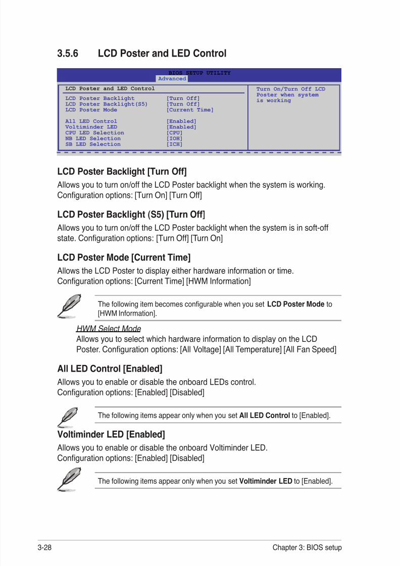
8/9/2019 Manual Placa Base Asus Rampage II Gene
http://slidepdf.com/reader/full/manual-placa-base-asus-rampage-ii-gene 98/176
3-28 Chapter 3: BIOS setup
3.5.6 LCD Poster and LED Control
LCD Poster Backlight [Turn Off]
Allows you to turn on/off the LCD Poster backlight when the system is working.Con guration options: [Turn On] [Turn Off]
LCD Poster Backlight (S5) [Turn Off]Allows you to turn on/off the LCD Poster backlight when the system is in soft-offstate. Con guration options: [Turn Off] [Turn On]
LCD Poster Mode [Current Time]Allows the LCD Poster to display either hardware information or time.
Con guration options: [Current Time] [HWM Information]
The following item becomes con gurable when you setLCD Poster Mode to[HWM Information].
HWM Select Mode Allows you to select which hardware information to display on the LCDPoster. Con guration options: [All Voltage] [All Temperature] [All Fan Speed]
All LED Control [Enabled]Allows you to enable or disable the onboard LEDs control.Con guration options: [Enabled] [Disabled]
The following items appear only when you set All LED Control to [Enabled].
Voltiminder LED [Enabled]Allows you to enable or disable the onboard Voltiminder LED.Con guration options: [Enabled] [Disabled]
The following items appear only when you set Voltiminder LED to [Enabled].
BIOS SETUP UTILITY Advanced
LCD Poster and LED Control
LCD Poster Backlight [Turn Off]LCD Poster Backlight(S5) [Turn Off]LCD Poster Mode [Current Time]
All LED Control [Enabled] Voltiminder LED [Enabled]
CPU LED Selection [CPU] NB LED Selection [IOH]
SB LED Selection [ICH]
Turn On/Turn Off LCDPoster when systemis working

8/9/2019 Manual Placa Base Asus Rampage II Gene
http://slidepdf.com/reader/full/manual-placa-base-asus-rampage-ii-gene 99/176
ROG Rampage II GENE 3-29
CPU LED Selection [CPU]Allows you to switch the onboard CPU LED display between CPU voltage [CPU],CPU PLL voltage [CPU PLL] and QPI/DRAM Core voltage [QPI/DRAM Core].Con guration options: [CPU] [CPU PLL] [QPI/DRAM Core]
NB LED Selection [IOH]Allows you to switch the onboard northbridge LED display between I/O Hubvoltage [IOH] and IOH PCIE voltage [IOH PCIE].Con guration options: [IOH] [IOH PCIE]
SB LED Selection [ICH]Allows you to switch the onboard southbridge LED display between I/O ControllerHub voltage [ICH] and ICH PCIE voltage [ICH PCIE].Con guration options: [ICH] [ICH PCIE]
3.5.7 iROG Con guration
iROG Timer Keeper [Last State]Allows you to set the iROG Time Keeper operation mode.Con guration options: [Last State] [Disabled] [Enabled]
BIOS SETUP UTILITY Advanced
iROG Con guration
iROG ID_Number InformationiROG BC_Number: A2
iROG_1 ID_Number: 26iROG_2 ID_Number: 4
iROG Timer Keeper [Last State]Current Operation time:
Total Operation time:
iROG Timer KeeperSystem will recordusing time every 1
minute

8/9/2019 Manual Placa Base Asus Rampage II Gene
http://slidepdf.com/reader/full/manual-placa-base-asus-rampage-ii-gene 100/176
3-30 Chapter 3: BIOS setup
3.6 Power menuThe Power menu items allow you to change the settings for the AdvancedPower Management (APM). Select an item then press <Enter> to display thecon guration options.
3.6.1 Suspend Mode [Auto]Allows you to select the Advanced Con guration and Power Interface (ACPI) stateto be used for system suspend.
Con guration options: [S1 (POS) Only] [S3 Only] [Auto]
3.6.2 Repost Video on S3 Resume [No]Determines whether to invoke VGA BIOS POST on S3/STR resume.Con guration options: [No] [Yes]
3.6.3 ACPI 2.0 Support [Disabled]Speci es the Advanced Con guration and Power Interface (ACPI) version
supported. Con guration options: [Disabled] [Enabled]
3.6.4 ACPI APIC Support [Enabled]Allows you to enable or disable the Advanced Con guration and Power Interface(ACPI) support in the Advanced Programmable Interrupt Controller (APIC). Whenset to Enabled, the ACPI APIC table pointer is included in the RSDT pointer list.Con guration options: [Disabled] [Enabled]
v02.61 (C)Copyright 1985-2009, American Megatrends, Inc.
BIOS SETUP UTILITYExtreme Tweaker Main Advanced Main Advanced Power Boot Tools Exit
Select the ACPI stateused for SystemSuspend.
←→ Select Screen↑↓ Select Item +- Change OptionF1 General HelpF10 Save and ExitESC Exit
Suspend Mode [Auto]Repost Video on S3 Resume [No]
ACPI 2.0 Support [Disabled] ACPI APIC Support [Enabled]
APM Con guration Hardware Monitor

8/9/2019 Manual Placa Base Asus Rampage II Gene
http://slidepdf.com/reader/full/manual-placa-base-asus-rampage-ii-gene 101/176
ROG Rampage II GENE 3-31
3.6.5 APM Con guration
Restore On AC Power Loss [Power Off]
When set to Power Off, the system goes into off state after an AC power loss.When set to Power On, the system goes on after an AC power loss. When set toLast State, the system goes into either off or on state, whatever the system statewas before the AC power loss.Con guration options: [Power Off] [Power On] [Last State]
Power On By RTC Alarm [Disabled]Allows you to enable or disable RTC to generate a wake event. When this itemis set to Enabled, the items RTC Alarm Date (Days) / System Time will become
user-con gurable with set values. Con guration options: [Disabled] [Enabled]Power On By PCI Devices [Disabled]Allows you to enable or disable the PME to wake up from S5 by PCI devices.Con guration options: [Disabled] [Enabled]
Power On By PCIE Devices [Disabled]Allows you to enable or disable the PCIE devices to generate a wake event.Con guration options: [Disabled] [Enabled]
Power On By PS/2 Keyboard [Disabled]Allows you to enable or disable the Power On by PS/2 keyboard function. Thisfeature requires an ATX power supply that provides at least 1A on the +5VSB lead.Con guration options: [Disabled] [Enabled]Enabled]]
BIOS SETUP UTILITY Power
APM Con guration
Restore on AC Power Loss [Power Off]
Power On By RTC Alarm [Disabled]Power On By PCI Devices [Disabled]Power On By PCIE Devices [Disabled]Power On By PS/2 Keyboard [Disabled]
OptionsPower OffPower OnLast State

8/9/2019 Manual Placa Base Asus Rampage II Gene
http://slidepdf.com/reader/full/manual-placa-base-asus-rampage-ii-gene 102/176

8/9/2019 Manual Placa Base Asus Rampage II Gene
http://slidepdf.com/reader/full/manual-placa-base-asus-rampage-ii-gene 103/176
ROG Rampage II GENE 3-33
CPU Q-Fan Control [Disabled] Allows you to enable or disable the CPU Q-fan control feature.Con guration options: [Disabled] [Enabled]
The following item appears when you enable CPU Q-Fan Control .
CPU Fan Pro le [Standard]Allows you to set the appropriate performance level of the ASUS Q-Fan. Whenset to [Standard], the CPU fan automatically adjusts depending on the CPUtemperature. Set this item to [Silent] to minimize fan speed for quiet CPU fanoperation, or [Turbo] to achieve maximum CPU fan speed.Con guration options: [Standard] [Silent] [Turbo]
Chassis Q-Fan Control [Disabled] Allows you to enable or disable the chassis Q-fan control feature.Con guration options: [Disabled] [Enabled]
The following item appears when you enable Chassis Q-Fan Control .
Chassis Fan Pro le [Standard]Allows you to set the appropriate performance level of the ASUS Q-Fan. Whenset to [Standard], the chassis fan automatically adjusts depending on the chassistemperature. Set this item to [Silent] to minimize fan speed for quiet chassis fanoperation, or [Turbo] to achieve maximum chassis fan speed.Con guration options: [Standard] [Silent] [Turbo]
OPTFan1/2 Control [Disabled] Allows you to select the optional fan control mode. When this item is set to[Duty Mode], you can con gure theOPTFan1/2 Duty item. If you set this itemto [User Mode], you are allowed to con gure theOPTFan1/2 Low SpeedTemp and OPTFan1/2 Full Speed Temp item.Con guration options: [Disabled] [Duty Mode] [User Mode]
You need to connect the thermal sensor cables to the OPT_TEMP1/2connectors to enable this function.
Fan Speed Control
BIOS SETUP UTILITY Power
Fan Speed ControlCPU Q-Fan Control [Disabled]Chassis Q-Fan Control [Disabled]
OPTFan1 Control [Disabled] [Disabled]OPTFan2 Control [Disabled]
CPU Q-Fan Control

8/9/2019 Manual Placa Base Asus Rampage II Gene
http://slidepdf.com/reader/full/manual-placa-base-asus-rampage-ii-gene 104/176
3-34 Chapter 3: BIOS setup
OPTFan1/2 Duty [50%]Allows you to set the fan duty cycle. This item appears when the OPTFan1/2Control item is set to [Duty Mode].Con guration options: [40%] [50%] [60%] [70%] [80%] [90%]
OPTFan1/2 Low Speed Temp [25˚C]Allows you to set the temperature at which the power fan rotates at low speed.This item appears when the OPTFan1/2 Control item is set to [User Mode].Con guration options: [25˚C] [30˚C] [35˚C] [40˚C]
OPTFan1/2 Full Speed Temp [60˚C]Allows you to set the temperature at which the power fan rotates at full speed.This item appears when the OPTFan1/2 Control item is set to [User Mode].Con guration options: [60˚C] [70˚C] [80˚C] [90˚C]

8/9/2019 Manual Placa Base Asus Rampage II Gene
http://slidepdf.com/reader/full/manual-placa-base-asus-rampage-ii-gene 105/176
ROG Rampage II GENE 3-35
3.7 Boot menuThe Boot menu items allow you to change the system boot options. Select an itemthen press <Enter> to display the sub-menu.
3.7.1 Boot Device Priority
1st–xxth Boot Device [xxx Drive]These items specify the boot device priority sequence from the available devices.The number of device items that appears on the screen depends on the number ofdevices installed in the system. Con guration options: [xxx Drive] [Disabled]
v02.61 (C)Copyright 1985-2009, American Megatrends, Inc.
BIOS SETUP UTILITY
Extreme Tweaker Main Advanced Power Main Advanced Power Boot Tools ExitSpeci es the BootDevice Prioritysequence.
A virtual oppy diskdrive (Floppy Drive B:) may appear when youset the CD-ROM driveas the rst bootdevice.
←→ Select Screen↑↓ Select Item
Enter Go to Sub ScreenF1 General HelpF10 Save and ExitESC Exit
Boot Settings
Boot Device Priority
Boot Settings Con guration Security
BIOS SETUP UTILITY Boot
Boot Device Priority
1st Boot Device [Hard Drive]2nd Boot Device [Removable Dev.]3rd Boot Device [ATAPI CD-ROM]
Speci es the boot
sequence from theavailabe devices.
A device enclosed in parenthesis has been
disabled in thecorresponding type
menu.

8/9/2019 Manual Placa Base Asus Rampage II Gene
http://slidepdf.com/reader/full/manual-placa-base-asus-rampage-ii-gene 106/176
3-36 Chapter 3: BIOS setup
3.7.2 Boot Settings Con guration
Quick Boot [Enabled]Enabling this item allows the BIOS to skip some power on self tests (POST) while
booting to decrease the time needed to boot the system. When set to [Disabled],BIOS performs all the POST items. Con guration options: [Disabled] [Enabled]
Full Screen Logo [Enabled]This allows you to enable or disable the full screen logo display feature.Con guration options: [Disabled] [Enabled]
Set this item to [Enabled] to use the ASUS MyLogo3 ™ feature.
AddOn ROM Display Mode [Force BIOS]Sets the display mode for option ROM.Con guration options: [Force BIOS] [Keep Current]
Bootup Num-Lock [On]Allows you to select the power-on state for the NumLock.Con guration options: [Off] [On]
Wait for ‘F1’ If Error [Enabled]When set to Enabled, the system waits for the F1 key to be pressed when erroroccurs. Con guration options: [Disabled] [Enabled]
Hit ‘DEL’ Message Display [Enabled]When set to Enabled, the system displays the message “Press DEL to run Setup”during POST. Con guration options: [Disabled] [Enabled]
BIOS SETUP UTILITY Boot
Boot Settings Con guration
Quick Boot [Enabled]Full Screen Logo [Enabled]
AddOn ROM Display Mode [Force BIOS]Bootup Num-Lock [On]
Wait for ‘F1’ if Error [Enabled]Hit ‘DEL’ Message Display [Enabled]
Allows BIOS to skipcertain tests while booting. This will
decrease the timeneeded to boot thesystem.

8/9/2019 Manual Placa Base Asus Rampage II Gene
http://slidepdf.com/reader/full/manual-placa-base-asus-rampage-ii-gene 107/176
ROG Rampage II GENE 3-37
Change Supervisor PasswordSelect this item to set or change the supervisor password. The SupervisorPassword item on top of the screen shows the default Not Installed. After you set apassword, this item shows Installed.
To set a Supervisor Password:
1. Select the Change Supervisor Password item and press <Enter>.2. From the password box, type a password composed of at least six letters
and/or numbers, then press <Enter>.3. Con rm the password when prompted.The message “Password Installed” appears after you successfully set yourpassword.
To change the supervisor password, follow the same steps as in setting a userpassword.
To clear the supervisor password, select the Change Supervisor Password thenpress <Enter>. The message “Password Uninstalled” appears.
If you forget your BIOS password, you can clear it by erasing the CMOS RealTime Clock (RTC) RAM. See section 2.6 Jumper for information on how toerase the RTC RAM.
3.7.3 SecurityThe Security menu items allow you to change the system security settings. Selectan item then press <Enter> to display the con guration options.
BIOS SETUP UTILITY Boot
Security Settings
Supervisor Password :Not Installed User Password :Not Installed
Change Supervisor Password Change User Password
<Enter> to change password. <Enter> again to
disabled password.

8/9/2019 Manual Placa Base Asus Rampage II Gene
http://slidepdf.com/reader/full/manual-placa-base-asus-rampage-ii-gene 108/176
3-38 Chapter 3: BIOS setup
User Access Level [Full Access]This item allows you to select the access restriction to the Setup items.Con guration options: [No Access] [View Only] [Limited] [Full Access]
[No Access] prevents user access to the Setup utility.[View Only] allows access but does not allow change to any eld.[Limited] allows changes only to selected elds, such as Date and Time.[Full Access] allows viewing and changing all the elds in the Setup utility.
Change User Password
Select this item to set or change the user password. The User Password item ontop of the screen shows the default Not Installed. After you set a password, thisitem shows Installed.
To set a User Password:
1. Select the Change User Password item and press <Enter>.2. On the password box that appears, type a password composed of at least six
letters and/or numbers, then press <Enter>.3. Con rm the password when prompted.The message “Password Installed” appears after you set your password successfully.
To change the user password, follow the same steps as in setting a user password.
Clear User PasswordSelect this item to clear the user password.
Password Check [Setup]When set to [Setup], BIOS checks for user password when accessing the Setuputility. When set to [Always], BIOS checks for user password both when accessingSetup and booting the system. Con guration options: [Setup] [Always]
After you have set a supervisor password, the other items appear to allow you tochange other security settings.
BIOS SETUP UTILITY BootSecurity Settings
Supervisor Password :Installed User Password :Installed
Change Supervisor Password User Access Level [Full Access]Change User Password Clear User Password Password Check [Setup]
<Enter> to change password. <Enter> again to
disabled password.

8/9/2019 Manual Placa Base Asus Rampage II Gene
http://slidepdf.com/reader/full/manual-placa-base-asus-rampage-ii-gene 109/176
ROG Rampage II GENE 3-39
3.8.1 ASUS EZ Flash 2Allows you to run ASUS EZ Flash 2. When you press <Enter>, a con rmationmessage appears. Use the left/right arrow key to select between [Yes] or [No], thenpress <Enter> to con rm your choice.
For more details, refer to section 3.1.2 ASUS EZ Flash 2 utility .
ASUSTek EZ Flash 2 BIOS ROM Utility V3.34
Current ROM Update ROM
A:
Note [Enter] Select or Load [Tab] Switch [V] Drive Info
[Up/Down/Home/End] Move [B] Backup [Esc] Exit
FLASH TYPE: MXIC 25L1605A
PATH: A:\
BOARD: RampageII GENE VER: 0208
DATE: 02/03/2009
BOARD: Unknown VER: Unknown
DATE: Unknown
3.8 Tools menuThe Tools menu items allow you to con gure options for special functions. Selectan item then press <Enter> to display the sub-menu.
v02.61 (C)Copyright 1985-2009, American Megatrends, Inc.
BIOS SETUP UTILITYExtreme Tweaker Main Advanced Power Boot Tools Exit
Press ENTER to runthe utility to selectand update BIOS.This utility supports1.FAT 12/16/32 (r/w)2.NTFS (read only)3.CD-DISC (read only)
←→ Select Screen↑↓ Select Item
Enter Go to Sub ScreenF1 General HelpF10 Save and ExitESC Exit
ASUS EZ Flash 2
ASUS O.C. Pro le TweakIt Batch File AI NET 2
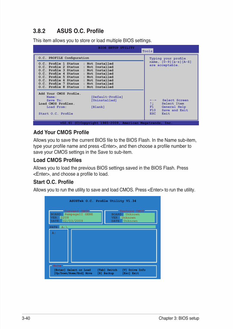
8/9/2019 Manual Placa Base Asus Rampage II Gene
http://slidepdf.com/reader/full/manual-placa-base-asus-rampage-ii-gene 110/176
3-40 Chapter 3: BIOS setup
3.8.2 ASUS O.C. Pro leThis item allows you to store or load multiple BIOS settings.
Add Your CMOS Pro leAllows you to save the current BIOS le to the BIOS Flash. In the Name sub-item,type your pro le name and press <Enter>, and then choose a pro le number tosave your CMOS settings in the Save to sub-item.
Load CMOS Pro lesAllows you to load the previous BIOS settings saved in the BIOS Flash. Press<Enter>, and choose a pro le to load.Start O.C. Pro leAllows you to run the utility to save and load CMOS. Press <Enter> to run the utility.
ASUSTek O.C. Pro le Utility V1.34
Restore CMOS
A:
Note [Enter] Select or Load [Tab] Switch [V] Drive Info
[Up/Down/Home/End] Move [B] Backup [Esc] Exit
PATH: A:\
BOARD: RampageII GENE VER: 0208
DATE: 02/03/2009
BOARD: Unknown VER: Unknown
DATE: Unknown
Current CMOS
v02.61 (C)Copyright 1985-2009, American Megatrends, Inc.
BIOS SETUP UTILITY Tools
Typing your pro lename, [0-9][a-z][A-Z]are acceptable.
←→ Select Screen↑↓ Select ItemF1 General HelpF10 Save and ExitESC Exit
O.C. PROFILE Con guration
O.C. Pro le 1 Status : Not Installed O.C. Pro le 2 Status : Not Installed O.C. Pro le 3 Status : Not Installed O.C. Pro le 4 Status : Not Installed O.C. Pro le 5 Status : Not Installed O.C. Pro le 6 Status : Not Installed O.C. Pro le 7 Status : Not Installed O.C. Pro le 8 Status : Not Installed
Add Your CMOS Pro le. Name: [Default-Pro le] Save To: [Uninstalled]Load CMOS Pro les. Load From: [Blank]
Start O.C. Pro le

8/9/2019 Manual Placa Base Asus Rampage II Gene
http://slidepdf.com/reader/full/manual-placa-base-asus-rampage-ii-gene 111/176
ROG Rampage II GENE 3-41
3.8.3 TweakIt Batch File
This menu allows you to set the TweakIt batch les, and load the desired TweakItbatch le.
• This function supports devices such as a USB ash disk (FAT 32/16format) or a oppy disk with single partition only.
• DO NOT shut down or reset the system while updating the BIOS toprevent the system boot failure!
• We recommend that you update the BIOS le only coming from thesame memory/CPU con guration and BIOS version.
• Only the CMO le can be loaded.
Save TweakIt Batch File to:Allows you to save the adjusted values for speci c items as a TweakIt batch le.Con guration options: [None] [File 1] [File 2]
Load TweakIt Batch File to:Allows you to load the desired TweakIt batch le.Con guration options: [None] [File 1] [File 2]
BCLK Frequency; CPU Ratio Setting; CPU Voltage; CPU PLL Voltage;QPI/DRAM Core Voltage; IOH Voltage; IOH PCIE Voltage; ICH Voltage;ICH PCIE Voltage; DRAM Bus VoltageAllows you to use the <+> and <-> keys to adjust the values for each item. Refer to3.3 Extreme Tweaker Menu for details.
v02.61 (C)Copyright 1985-2009, American Megatrends, Inc.
BIOS SETUP UTILITY Tools
Save TweakIt BatchFile
←→ Select Screen↑↓ Select Item +- Change OptionF1 General HelpF10 Save and ExitESC Exit
TweakIt Batch File
Save TweakIt Batch File to: [None]Load TweakIt Batch File From: [None] BCLK Frequency [Auto] CPU Ratio Setting [Auto] CPU Voltage [Auto] CPU PLL Voltage [Auto] QPI/DRAM Core Voltage [Auto] IOH Voltage [Auto] IOH PCIE Voltage [Auto] ICH Voltage [Auto] ICH PCIE Voltage [Auto] DRAM Bus Voltage [Auto]

8/9/2019 Manual Placa Base Asus Rampage II Gene
http://slidepdf.com/reader/full/manual-placa-base-asus-rampage-ii-gene 112/176
3-42 Chapter 3: BIOS setup
3.8.4 AI NET 2
Check Realtek LAN cable [Disabled]Enables or disables checking of the LAN cable during the Power-On Self-Test(POST). Con guration options: [Disabled] [Enabled]
BIOS SETUP UTILITY Tools
Ai Net 2Pair Status Length
Check Realtek LAN cable [Disabled]
Check Realtek LANcable during POST.
It will take 3 to 10seconds to diagnoseLAN cable.

8/9/2019 Manual Placa Base Asus Rampage II Gene
http://slidepdf.com/reader/full/manual-placa-base-asus-rampage-ii-gene 113/176
ROG Rampage II GENE 3-43
3.9 Exit menuThe Exit menu items allow you to load the optimal or failsafe default values for theBIOS items, and save or discard your changes to the BIOS items.
Pressing <Esc> does not immediately exit this menu. Select one of the optionsfrom this menu or <F10> from the legend bar to exit.
Exit & Save ChangesOnce you are nished making your selections, choose this option from the Exit
menu to ensure the values you selected are saved to the CMOS RAM. An onboardbackup battery sustains the CMOS RAM so it stays on even when the PC is turnedoff. When you select this option, a con rmation window appears. Select YES tosave changes and exit.
If you attempt to exit the Setup program without saving your changes, theprogram prompts you with a message asking if you want to save your changesbefore exiting. Press <Enter> to save the changes while exiting.
Exit & Discard ChangesSelect this option only if you do not want to save the changes that you made tothe Setup program. If you made changes to elds other than System Date, SystemTime, and Password, the BIOS asks for a con rmation before exiting.
Discard ChangesThis option allows you to discard the selections you made and restore thepreviously saved values. After selecting this option, a con rmation appears. SelectYES to discard any changes and load the previously saved values.
Load Setup DefaultsThis option allows you to load the default values for each of the parameters on theSetup menus. When you select this option or if you press <F5>, a con rmationwindow appears. Select YES to load default values. Select Exit & Save Changesor make other changes before saving the values to the non-volatile RAM.
v02.61 (C)Copyright 1985-2009, American Megatrends, Inc.
BIOS SETUP UTILITY Main Extreme Tweaker Advanced Power Boot Tools Exit
Exit system setup aftersaving the changes.
F10 key can be used forthis operation.
←→ Select Screen↑↓ Select Item Enter Go to Sub ScreenF1 General HelpF10 Save and ExitESC Exit
Exit Options
Exit & Save ChangesExit & Discard ChangesDiscard Changes
Load Setup Defaults

8/9/2019 Manual Placa Base Asus Rampage II Gene
http://slidepdf.com/reader/full/manual-placa-base-asus-rampage-ii-gene 114/176
3-44 Chapter 3: BIOS setup

8/9/2019 Manual Placa Base Asus Rampage II Gene
http://slidepdf.com/reader/full/manual-placa-base-asus-rampage-ii-gene 115/176
4Softwaresupport
This chapter describes the contents ofthe support DVD that comes with themotherboard package and the software.

8/9/2019 Manual Placa Base Asus Rampage II Gene
http://slidepdf.com/reader/full/manual-placa-base-asus-rampage-ii-gene 116/176
ROG Rampage II GENE
Chapter summary 44.1 Installing an operating system ................................................... 4-14.2 Support DVD information ............................................................ 4-14.3 Software information ................................................................... 4- 94.4 RAID con gurations .................................................................. 4- 334.5 Creating a RAID driver disk ....................................................... 4- 40

8/9/2019 Manual Placa Base Asus Rampage II Gene
http://slidepdf.com/reader/full/manual-placa-base-asus-rampage-ii-gene 117/176
ROG Rampage II GENE 4-1
If Autorun is NOT enabled in your computer, browse the contents of the supportDVD to locate the le ASSETUP.EXE from the BIN folder. Double-click theASSETUP.EXE to run the DVD.
4.1 Installing an operating systemThis motherboard supports Windows ® XP/64-bit XP/Vista operating systems (OS).XP/64-bit XP/Vista operating systems (OS).operating systems (OS).Always install the latest OS version and corresponding updates to maximize thefeatures of your hardware.
4.2 Support DVD informationThe support DVD that came with the motherboard package contains the drivers,software applications, and utilities that you can install to avail all motherboard features.
4.2.1 Running the support DVD
Place the support DVD to the optical drive. The DVD automatically displays theDrivers menu if Autorun is enabled in your computer.
• Motherboard settings and hardware options vary. Use the setupprocedures presented in this chapter for reference only. Refer to your OSdocumentation for detailed information.
• Ensure that you install Windows ® XP Service Pack 2 or later versionsbefore installing the drivers for better compatibility and system stability.
The contents of the support DVD are subject to change at any time withoutnotice. Visit the ASUS website (www.asus.com) for updates.
Click an icon todisplay supportDVD/motherboardinformation
Click an item to install

8/9/2019 Manual Placa Base Asus Rampage II Gene
http://slidepdf.com/reader/full/manual-placa-base-asus-rampage-ii-gene 118/176
4-2 Chapter 4: Software support
4.2.2 Drivers menuThe drivers menu shows the available device drivers if the system detects installeddevices. Install the necessary drivers to activate the devices.
ASUS InstAll - Drivers Installation WizardLaunches the ASUS InstAll driver installation wizard.
Intel Chipset Inf Update ProgramInstalls the Intel ® chipset inf update program.
SoundMAX ADI Audio DriverInstalls the SoundMAX® audio driver and application.
Realtek RTL8111B/C LAN DriverInstalls the Realtek ® Gigabit Ethernet Driver.
JMicron JMB36X Controller DriverInstalls the JMicron® JMB36X controller driver.
Sound Blaster X-FiInstalls the Sound Blaster X-Fi driver and utility.
ASUS TweakItInstalls the ASUS TweakIt driver and utility.

8/9/2019 Manual Placa Base Asus Rampage II Gene
http://slidepdf.com/reader/full/manual-placa-base-asus-rampage-ii-gene 119/176
ROG Rampage II GENE 4-3
4.2.3 Utilities menuThe Utilities menu shows the applications and other software that the motherboardsupports.
Click to displaythe next screen
Click to display theprevious screen
ASUS InstAll - Installation Wizard for Utilities
Installs all of the utilities through the Installation Wizard.ASUS UpdateThe ASUS Update utility allows you to update the motherboard BIOS in Windows ® environment. This utility requires an Internet connection either through a networkor an Internet Service Provider (ISP).
ASUS PC Probe IIThis smart utility monitors the fan speed, CPU temperature, and system voltages,
and alerts you of any detected problems. This utility helps you keep your computerin healthy operating condition.

8/9/2019 Manual Placa Base Asus Rampage II Gene
http://slidepdf.com/reader/full/manual-placa-base-asus-rampage-ii-gene 120/176
4-4 Chapter 4: Software support
ASUS AI SuiteInstalls the ASUS AI Suite.
ASUS AI Direct LinkThe ASUS AI Direct Link provides up to 70% transferring speed improvement whencompared to traditional USB 2.0 and is the easiest and fastest way for users toenjoy large-sized data exchange of les such as movies, music, etc.
ASUS TurboVInstalls ASUS TurboV, the advanced overclocking tool for extreme O.C. record.
ASUS EPU-6 EngineInstalls the ASUS EPU-6 Engine driver and utility.
Adobe Reader 8Installs the Adobe ® Reader that allows you to open, view, and print documents inPortable Document Format (PDF).
Anti-Virus UtilityThe anti-virus application scans, identi es, and removes computer viruses. View
the online help for detailed information.3DMark06 SoftwareInstalls the Futuremark ® 3DMark06 system benchmark application.
Corel MediaOne StarterInstalls the Corel MediaOne Starter application to easily manage, edit share andprotect your multimedia data.
Ulead Burn.NowInstalls the Ulead Burn.Now application for Audio DVD, CD and data disc creation.
Ulead PhotoImpact 12 SEInstalls the Ulead PhotoImpact 12 SE software.
Winzip 11Installs the Winzip utility for easy le-compression and protection.

8/9/2019 Manual Placa Base Asus Rampage II Gene
http://slidepdf.com/reader/full/manual-placa-base-asus-rampage-ii-gene 121/176
ROG Rampage II GENE 4-5
4.2.4 Make disk menuThe Make disk menu contains items to create the Intel ICH10R driver disk.
Intel ICH10R 32/64 bit AHCI/RAID DriverAllows you to create an ICH10R 32/64bit AHCI/RAID driver disk.
JMicron JMB36X 32/64 bit RAID/AHCI DriverAllows you to create a JMicron ® JMB36X RAID/AHCI driver disk for 32/64bitsystem.
4.2.5 Manual menuThe Manuals menu contains a list of supplementary user manuals. Click an item toopen the folder of the user manual.
Most user manual les are in Portable Document Format (PDF). Install theAdobe® Acrobat® Reader from the Utilities menu before opening a user manual
le.

8/9/2019 Manual Placa Base Asus Rampage II Gene
http://slidepdf.com/reader/full/manual-placa-base-asus-rampage-ii-gene 122/176
4-6 Chapter 4: Software support
4.2.7 ASUS Contact informationClick the Contact tab to display the ASUS contact information. You can also ndthis information on the inside front cover of this user guide.
4.2.6 Video menuClick the Video tab to display a list of video clips. Click the video titles to watchROG users’ outstanding performances with ROG motherboards.

8/9/2019 Manual Placa Base Asus Rampage II Gene
http://slidepdf.com/reader/full/manual-placa-base-asus-rampage-ii-gene 123/176
ROG Rampage II GENE 4-7
4.2.8 Other informationThe icons on the top right corner of the screen give additional information on themotherboard and the contents of the support DVD. Click an icon to display the
speci ed information.Motherboard InfoDisplays the general speci cations of the motherboard.
Browse this DVDDisplays the support DVD contents in graphical format.

8/9/2019 Manual Placa Base Asus Rampage II Gene
http://slidepdf.com/reader/full/manual-placa-base-asus-rampage-ii-gene 124/176
4-8 Chapter 4: Software support
FilelistDisplays the contents of the support DVD and a brief description of each in text format.
Technical support formDisplays the ASUS Technical Support Request Form that you have to ll out whenrequesting technical support.

8/9/2019 Manual Placa Base Asus Rampage II Gene
http://slidepdf.com/reader/full/manual-placa-base-asus-rampage-ii-gene 125/176
ROG Rampage II GENE 4-9
4.3 Software informationMost of the applications in the support DVD have wizards that will convenientlyguide you through the installation. View the online help or readme le that camewith the software application for more information.
4.3.1 ASUS MyLogo3™The ASUS MyLogo3™ utility lets you customize the boot logo. The boot logo is theimage that appears on screen during the Power-On Self-Tests (POST). The ASUSMyLogo3™ is automatically installed when you install the ASUS Update utility fromthe support DVD. See section 4.2.3 Utilities menu for details.
To launch the ASUS MyLogo3™:™::
1. Launch the ASUS Update utility. Refer to section 3.1.1 ASUS Update utility for details.2. Select Options from the drop down menu, then click Next .3. Check the option Launch MyLogo to replace system boot logo before
ashing BIOS, then clickNext .4. Select Update BIOS from a le from the drop down menu, then clickNext .5. When prompted, locate the new
BIOS le, then clickNext . The ASUSMyLogo window appears.
6. From the left window pane, select thefolder that contains the image youintend to use as your boot logo.
• Before using the ASUS MyLogo3 ™, use the ASUS Update utility to make a
copy of your original BIOS le, or obtain the latest BIOS version from theASUS website. See section 3.1.1 ASUS Update utility .
• Ensure that the BIOS item Full Screen Logo is set to [Enabled] if you wishto use ASUS MyLogo3™. See section 3.7.2 Boot Settings Con guration .
• You can create your own boot logo image in GIF le formats.

8/9/2019 Manual Placa Base Asus Rampage II Gene
http://slidepdf.com/reader/full/manual-placa-base-asus-rampage-ii-gene 126/176
4-10 Chapter 4: Software support
9. When the screen returns to the ASUS Update utility, ash the original BIOS toload the new boot logo.
10. After ashing the BIOS, restart the computer to display the new boot logoduring POST.
8. Adjust the boot image to your desiredsize by selecting a value on the Ratiobox.
7. When the logo images appear on theright window pane, select an image to
enlarge by clicking on it.

8/9/2019 Manual Placa Base Asus Rampage II Gene
http://slidepdf.com/reader/full/manual-placa-base-asus-rampage-ii-gene 127/176
ROG Rampage II GENE 4-11
4.3.2 Sound Blaster X-Fi audio utilityWith the SupremeFX X-Fi technology supported, you will be able to enjoy excellentaudio quality and experience realistic sound effects through the ADI AD2000B
audio codec and Sound Blaster X-Fi interface. Activating X-Fi’s CMSS3D,Crystalizer, and EAX will deliver accurate virtual surround sound and enhancedaudio dynamics, which amount to ultimate gaming experience.
To install Sound Blaster X-Fi:
1. Place the support DVD to the optical drive. The Drivers installation tabappears if your computer has an enabled Autorun feature.
2. Click the Drivers tab and click SoundMAX ADI Audio Driver .3. Follow the screen instructions to complete installation.4. Click the support DVD Utilities tab and click Sound Blaster X-Fi .5. Follow the screen instructions to complete installation.Follow the screen instructions to complete installation.
You need to install SoundMAX ADI Audio Driver to use Sound Blaster X-Fiaudio utility.
Double-click the Volume Panel icon tolaunch the Mixer control panel.
Click Main Display to goto the Main Panel.
If the Sound Blaster X-Fi audio utility is successfullyinstalled, you will nd theVolume Panel icon on
the noti cation area.Click the Volume Panel icon to display a list ofCreative ® media utilities that help you manageand play your media les. ClickHelp in each utilitycontrol panel to know more about them.

8/9/2019 Manual Placa Base Asus Rampage II Gene
http://slidepdf.com/reader/full/manual-placa-base-asus-rampage-ii-gene 128/176
4-12 Chapter 4: Software support
Main PanelThe Main Panel displays all the features and functions the SupremeFX X-Fisupports. Click each icon to con gure the following settings (from left to right):Speakers and Headphone, EAX Effects, X-Fi CMSS-3D, X-Fi Crystalizer, SmartVolume Management, Graphic Equalizer, and Mixer.
MinimizeExitHelp
Click to restoredefault settings
Click to mute volume
Drag to adjust volume
Click each icon tocon gure furthersettings
Speakers and Headphone PanelThis panel allows you to con gure speakers/headphone settings including bassmanagement and speaker volume. You can also test each speaker channel.
Click to test speakersound in turn
Click to test speakernoise in turn
Click to select aspeaker type
Click to adjust bass
Click to adjustvolume of each
speaker

8/9/2019 Manual Placa Base Asus Rampage II Gene
http://slidepdf.com/reader/full/manual-placa-base-asus-rampage-ii-gene 129/176

8/9/2019 Manual Placa Base Asus Rampage II Gene
http://slidepdf.com/reader/full/manual-placa-base-asus-rampage-ii-gene 130/176
4-14 Chapter 4: Software support
Smart Volume Management PanelEnable Smart Volume Management (SVM) to avoid large volume uctuations.
Click to switchon/off SVM
Graphic Equalizer PanelThis panel allows you to customize equalizer settings or select an EQ presets.
Click to select
an EQ preset
Click to savesettings
Click toenable EQ
Drag tocustomize
effects
Mixer PanelThis panel allows you to select a recording device and adjust recording/playbackdevices volume.
Click to adjustvolume
Click to mutevolume
Drag to adjust
volume
Click to selecta recording
device

8/9/2019 Manual Placa Base Asus Rampage II Gene
http://slidepdf.com/reader/full/manual-placa-base-asus-rampage-ii-gene 131/176
ROG Rampage II GENE 4-15
4.3.3 ASUS PC Probe IIPC Probe II is a utility that monitors the computer’s vital components, and detectsand alerts you of any problem with these components. PC Probe II senses fan
rotations, CPU temperature, and system voltages, among others. Because PCProbe II is software-based, you can start monitoring your computer the momentyou turn it on. With this utility, you are assured that your computer is always at ahealthy operating condition.
Installing PC Probe IITo install PC Probe II on your computer:
1. Place the support DVD to the optical drive. The Drivers installation tabappears if your computer has an enabled Autorun feature.
If Autorun is not enabled in your computer, browse the contents of the supportDVD to locate the setup.exe le from the ASUS PC Probe II folder. Double-clickthe setup.exe le to start installation.
2. Click the Utilities tab, then click ASUS PC Probe II .3. Follow the screen instructions to complete installation.
Launching PC Probe IIYou can launch the PC Probe II right after installation or anytime from theWindows® desktop.
To launch the PC Probe II from the Windows ® desktop, click Start > All Programs> ASUS > PC Probe II > PC Probe II v1.xx.xx . The PC Probe II main windowappears.
After launching the application, the PC Probe II icon appears in the Windows ® taskbar. Click this icon to close or restore the application.
Using PC Probe IIMain window The PC Probe II main windowallows you to view the currentstatus of your system and changethe utility con guration. Bydefault, the main window displaysthe Preference section. You can
close or restore the Preferencesection by clicking on the triangle on the main window right handle.
Click to close thePreference panel

8/9/2019 Manual Placa Base Asus Rampage II Gene
http://slidepdf.com/reader/full/manual-placa-base-asus-rampage-ii-gene 132/176
4-16 Chapter 4: Software support
Button FunctionOpens the Con guration windowOpens the Report window
Opens the Desktop Management Interface window
Opens the Peripheral Component Interconnect window
Opens the Windows Management Instrumentation window
Opens the hard disk drive, memory, CPU usage window
Shows/Hides the Preference section
Minimizes the application
Closes the application
Sensor alert When a system sensor detects a problem, the main window right handleturns red, as the illustrations below show.
When displayed, the monitor panel for that sensor also turns red. Refer to theMonitor panels section for details.
PreferencesYou can customize the application usingthe Preference section in the main window.Click the box before each preference toactivate or deactivate.
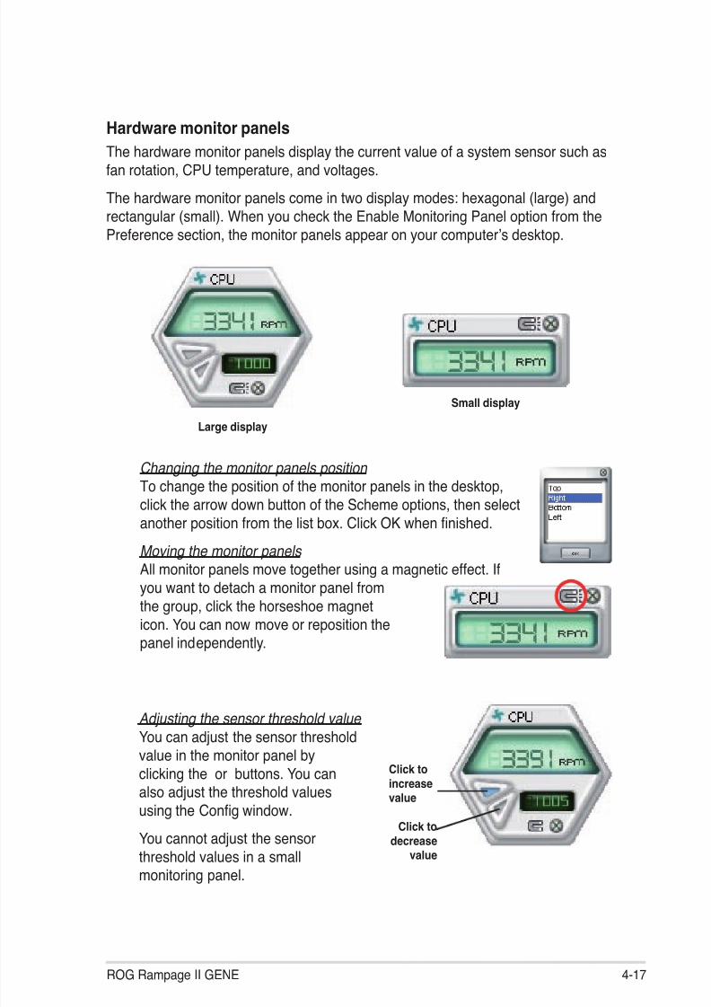
8/9/2019 Manual Placa Base Asus Rampage II Gene
http://slidepdf.com/reader/full/manual-placa-base-asus-rampage-ii-gene 133/176
ROG Rampage II GENE 4-17
Changing the monitor panels position To change the position of the monitor panels in the desktop,
click the arrow down button of the Scheme options, then selectanother position from the list box. Click OK when nished.
Moving the monitor panels All monitor panels move together using a magnetic effect. Ifyou want to detach a monitor panel fromthe group, click the horseshoe magneticon. You can now move or reposition thepanel independently.
Hardware monitor panelsThe hardware monitor panels display the current value of a system sensor such asfan rotation, CPU temperature, and voltages.The hardware monitor panels come in two display modes: hexagonal (large) andrectangular (small). When you check the Enable Monitoring Panel option from thePreference section, the monitor panels appear on your computer’s desktop.
Large display
Small display
Click toincreasevalue
Click to
decreasevalue
Adjusting the sensor threshold valueYou can adjust the sensor thresholdvalue in the monitor panel byclicking the or buttons. You canalso adjust the threshold valuesusing the Con g window.
You cannot adjust the sensorthreshold values in a smallmonitoring panel.

8/9/2019 Manual Placa Base Asus Rampage II Gene
http://slidepdf.com/reader/full/manual-placa-base-asus-rampage-ii-gene 134/176
4-18 Chapter 4: Software support
Monitoring sensor alert The monitor panel turns red when a component value exceeds or is lower
than the threshold value. Refer to the illustrations below.
Large display
Small display
WMI browser
Click to display theWMI (Windows ManagementInstrumentation) browser. Thisbrowser displays various Windows®management information. Click an
item from the left panel to display onthe right panel. Click the plus sign (+)before WMI Information to display theavailable information.
You can enlarge or reduce the browser size by dragging the bottom right cornerof the browser.
DMI browser
Click to display the DMI(Desktop Management Interface)browser. This browser displays variousdesktop and system information.Click the plus sign (+) before DMIInformation to display the availableinformation.

8/9/2019 Manual Placa Base Asus Rampage II Gene
http://slidepdf.com/reader/full/manual-placa-base-asus-rampage-ii-gene 135/176
ROG Rampage II GENE 4-19
PCI browser
Click to display the PCI(Peripheral Component Interconnect)browser. This browser providesinformation on the PCI devices installedon your system. Click the plus sign(+) before the PCI Information item todisplay available information.
UsageThe Usage browser displays real-time information on the CPU, hard disk drivespace, and memory usage. Click to display the Usage browser.
CPU usage The CPU tab displays real-time CPU usage in line graphrepresentation. If the CPU has
an enabled Hyper-Threading,two separate line graphs displaythe operation of the two logicalprocessors.
Hard disk drive space usage The Hard Disk tab displays the
used and available hard diskdrive space. The left panel of thetab lists all logical drives. Clicka hard disk drive to display theinformation on the right panel.The pie chart at the bottom ofthe window represents the used(blue) and the available HDDspace.

8/9/2019 Manual Placa Base Asus Rampage II Gene
http://slidepdf.com/reader/full/manual-placa-base-asus-rampage-ii-gene 136/176
4-20 Chapter 4: Software support
Memory usage The Memory tab shows both
used and available physicalmemory. The pie chart at thebottom of the window representsthe used (blue) and the availablephysical memory.
Con guring PC Probe IIClick to view and adjust the sensor threshold values.
The Con g window has two tabs: Sensor/Threshold and Preference. The Sensor/ Threshold tab enables you to activate the sensors or to adjust the sensor thresholdvalues. The Preference tab allows you to customize sensor alerts, or change thetemperature scale.
Loads the defaultthreshold values for
each sensor
Applies yourchanges
Cancels orignores your
changes
Loads your savedcon guration
Saves yourcon guration

8/9/2019 Manual Placa Base Asus Rampage II Gene
http://slidepdf.com/reader/full/manual-placa-base-asus-rampage-ii-gene 137/176

8/9/2019 Manual Placa Base Asus Rampage II Gene
http://slidepdf.com/reader/full/manual-placa-base-asus-rampage-ii-gene 138/176
4-22 Chapter 4: Software support
Other feature buttons
Click on right corner of the main window to open the monitor window.
Click on right corner of the expanded window to switch the temperature fromdegrees Centigrade to degrees Fahrenheit.
Displays the CPU/ system temperature,CPU/memory/PCIEvoltage, and CPU/ chassis fan speed
Displays the FSB/CPUfrequency

8/9/2019 Manual Placa Base Asus Rampage II Gene
http://slidepdf.com/reader/full/manual-placa-base-asus-rampage-ii-gene 139/176
ROG Rampage II GENE 4-23
4.3.5 ASUS AI NapThis feature allows you to minimize the power consumption of your computerwhenever you are away. Enable this feature for minimum power consumption and
a more quiet system operation.After installing AI Suite from the bundled support DVD, you can launch the utility bydouble-clicking the AI Suite icon on the Windows OS taskbar and click the AI Napbutton on the AI Suite main window.
Click Yes on the con rmation screen.
To exit AI Nap mode, press the system power or mouse button then click Yes onthe con rmation screen.
To switch the power button functions from AI Nap to shutting down, just rightclick the AI Suite icon on the OS taskbar, select AI Nap and click Use powerbutton . Unclick the the item to switch the function back.

8/9/2019 Manual Placa Base Asus Rampage II Gene
http://slidepdf.com/reader/full/manual-placa-base-asus-rampage-ii-gene 140/176
4-24 Chapter 4: Software support
4.3.6 ASUS Fan XpertAsus Fan Xpert intelligently allows you to adjust both the CPU and chassis fanspeeds according to different ambient temperatures caused by different climate
conditions in different geographic regions and your PC’s system loading. Thebuilt-in variety of useful pro les offer exible controls of fan speed to achieve aquiet and cool environment.
Install AI Suite from the bundled support DVD. To launch the ASUS Fan Xpertutility, double-click theAI Suite icon on the Windows ® noti cation bar and clickthe Fan Xpert button on the AI Suite main window.
Click the dropdown list button and display the fan types. Select CPU Fan orChassis Fan .
Dropdown list button
Click to displaythe dropdown list
and select a fanpro le mode
Click to displaythe current CPUtemperature and thefan speed ratio
Click to save the setup Click to cancel theFan Xpert utility
Click to open theCalibration wiondow

8/9/2019 Manual Placa Base Asus Rampage II Gene
http://slidepdf.com/reader/full/manual-placa-base-asus-rampage-ii-gene 141/176
ROG Rampage II GENE 4-25
Click to get the calibration betweenthe fan rotation and fan speed ratio
Click to close the Calibration window
Fan pro le modes
• Disable: Select this mode to disable the Fan Xpert function.• Standard: This mode makes the fan adjust speed in moderate pattern.• Silent: This mode minimizes fan speed for quiet fan operation.• Turbo: This mode boosts the fan to achieve maximal fan speed for the best
cooling effect.• Intelligent: This mode automatically adjusts the CPU fan speed with the
ambient temperature.• Stable: This mode keeps the CPU fan at the same speed to avoid noise
caused by the unsteady fan rotation. However, the fan will speed upwhen the temperature exceeds 70ºC.• User: This mode allows you to change the CPU fan pro le under certain
limitation.
For Chassis Fan , only Disable/Standard/Silent/Turbo modes could be selected.

8/9/2019 Manual Placa Base Asus Rampage II Gene
http://slidepdf.com/reader/full/manual-placa-base-asus-rampage-ii-gene 142/176
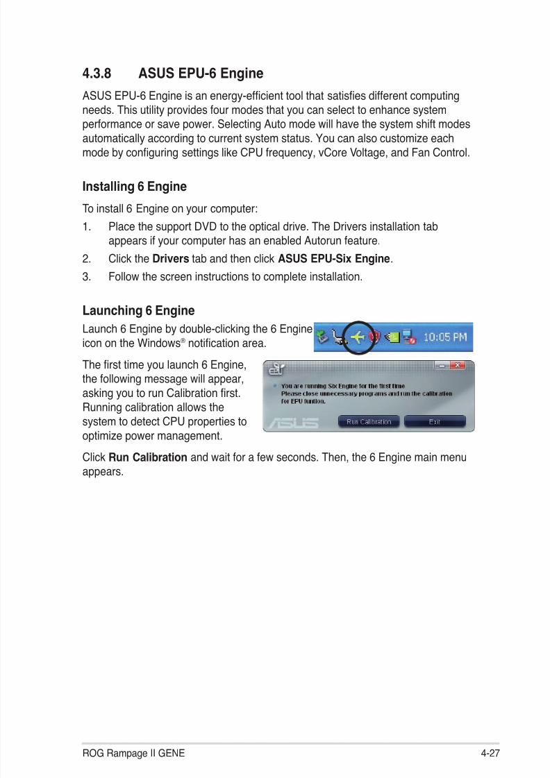
8/9/2019 Manual Placa Base Asus Rampage II Gene
http://slidepdf.com/reader/full/manual-placa-base-asus-rampage-ii-gene 143/176

8/9/2019 Manual Placa Base Asus Rampage II Gene
http://slidepdf.com/reader/full/manual-placa-base-asus-rampage-ii-gene 144/176
4-28 Chapter 4: Software support
6 Engine main menu
Auto Mode Runs calibrationTurbo Mode
High Performance Mode
Medium Power Saving Mode
Max. Power Saving Mode
Advanced settings for each mode (refer to the next page for further information)
Displays CPU Power and
Total CPU Energy Saving
*Shifts betweenthe display of Totaland Current CO2reduced
Displays theamount of CO2reduced
Displays the followingmessage if no VGA powersaving engine is detected.
Exits the utility
Displays the systemproperties of eachmode
Displayscurrent
mode
Lights up when powersaving engine is activated
*• ClickCurrent to show the CO2 that has been reduced sinceyou click the Renew button .
*• Click Total to show the total CO2 that has been reducedsince you launched 6 Engine.
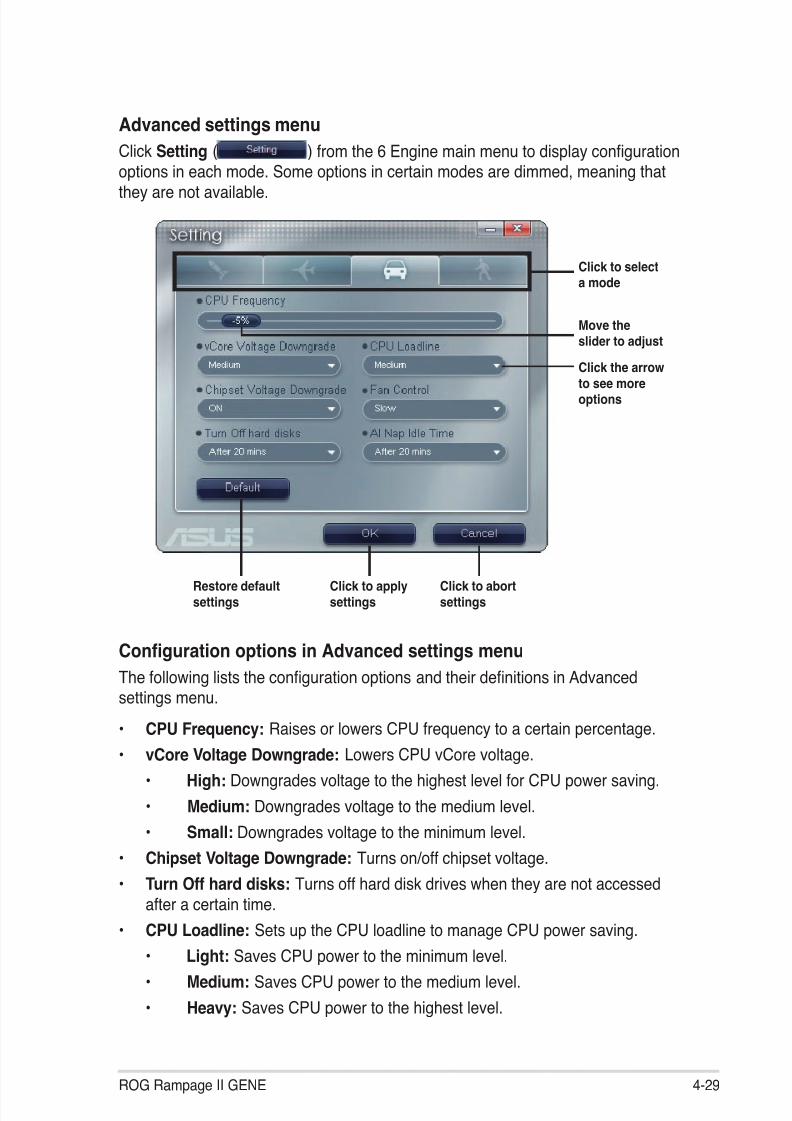
8/9/2019 Manual Placa Base Asus Rampage II Gene
http://slidepdf.com/reader/full/manual-placa-base-asus-rampage-ii-gene 145/176
ROG Rampage II GENE 4-29
Advanced settings menuClick Setting ( ) from the 6 Engine main menu to display con gurationoptions in each mode. Some options in certain modes are dimmed, meaning thatthey are not available.
Click to selecta mode
Move theslider to adjust
Click the arrowto see moreoptions
Restore defaultsettings
Click to applysettings
Click to abortsettings
Con guration options in Advanced settings menuThe following lists the con guration options and their de nitions in Advancedsettings menu.
• CPU Frequency: Raises or lowers CPU frequency to a certain percentage.
• vCore Voltage Downgrade: Lowers CPU vCore voltage. • High: Downgrades voltage to the highest level for CPU power saving. • Medium: Downgrades voltage to the medium level. • Small: Downgrades voltage to the minimum level.• Chipset Voltage Downgrade: Turns on/off chipset voltage.• Turn Off hard disks: Turns off hard disk drives when they are not accessed
after a certain time.
• CPU Loadline: Sets up the CPU loadline to manage CPU power saving. • Light: Saves CPU power to the minimum level. • Medium: Saves CPU power to the medium level. • Heavy: Saves CPU power to the highest level.

8/9/2019 Manual Placa Base Asus Rampage II Gene
http://slidepdf.com/reader/full/manual-placa-base-asus-rampage-ii-gene 146/176
4-30 Chapter 4: Software support
Con gurationoptions
Turbo Mode HighPerformanceMode
Medium PowerSaving Mode
MaximumPower SavingMode
CPU
Frequency
Overclocking
+1% to +30%
N/A Downclocking
-1% to -50%
Downclocking
-1% to -50%vCore VoltageDowngrade
N/A N/A Small/Medium/ High
Small/Medium/ High
ChipsetVoltageDowngrade
N/A N/A On/Off On/Off
Turn Offhard disks
Never/After 3mins–After 5hours
Never/After 3mins–After 5hours
Never/After 3mins–After 5hours
Never/After 3mins–After 5hours
CPU Loadline N/A N/A Light/Medium/ Heavy
Light/Medium/ Heavy
Fan Control N/A N/A Keep BiosSetting/Slow
Keep BiosSetting/Quiet
AI NapIdle Time
Never/After 3mins–After 5hours
Never/After 3mins–After 5hours
Never/After 3mins–After 5hours
Never/After 3mins–After 5hours
Refer to the following table for the con guration options in each mode.
• Fan Control: Adjusts fan speeds to reduce noise and save system power. • Quiet: Lowers CPU fan speed and shuts off two chassis fans. • Slow: Lowers CPU fan and two chassis fan speeds.• AI Nap Idle Time: Enters AI Nap mode after a certain time during system idle
process.
The TweakIt function isdisabled when 6-Engineis set to Auto Mode. Toenable TweakIt function,set 6-Engine to other modeoption. Or, you may clickthe TweakIt icon on theWindows® noti cation area
and click Unlock to enablethe TweakIt function.
Ensure that you’ve installed TweakIt driver from the bundled Support DVD.

8/9/2019 Manual Placa Base Asus Rampage II Gene
http://slidepdf.com/reader/full/manual-placa-base-asus-rampage-ii-gene 147/176
ROG Rampage II GENE 4-31
4.3.9 ASUS TurboVASUS TurboV allows you to overclock the CPU frequency, CPU voltage, QPI/ Memory controller voltage, and DRAM voltage in WIndows® environment and takes
effect in real-time without exiting and rebooting the OS.Refer to the CPU documentation before adjusting CPU voltage settings. Settinga high voltage may damage the CPU permanently, and setting a low voltagemay make the system unstable.
• For system stability, all changes made in ASUS TurboV will not be savedto BIOS settings and will not be kept on the next system boot. Use theSave Pro le function to save your customized overclocking settings andmanually load the pro le after Windows starts.
• For system stability, set ASUS EPU 6-Engine to High Performance Mode while using ASUS TurboV.
To launch ASUS TurboV
1. Install the ASUS TurboV utility from the motherboard support DVD.2. Click start > All Programs > ASUS > TurboV > TurboV .
Save the current settings as a pro le
Shows moresettings
Applies allchangesimmediately
Undoes allchangeswithoutapplying
VoltageAdjustmentbars
Defaultsettings
Targetsettings
Overclocking tips:
• For advanced overclockability, adjust rst theExtreme Tweaker items inBIOS, and then proceed more detailed adjustments using TurboV.
• The BCLK Frequency setting in BIOS affects the adjustable range of CPUFrequency in TurboV.For advanced overclocking: Set BCLK Frequency in BIOS to 200MHz orabove for an adjustment range from 200MHz to 500MHz in TurboV. For general overclocking: Set BCLK Frequency in BIOS below 200MHz foran adjustment range from 100MHz to 250MHz in TurboV.

8/9/2019 Manual Placa Base Asus Rampage II Gene
http://slidepdf.com/reader/full/manual-placa-base-asus-rampage-ii-gene 148/176
4-32 Chapter 4: Software support
Advanced settings menuClick More Setting from the TurboV main screen to display detailed con gurationoptions for CPU/chip voltage, DRAM Reference voltage, and CPU ratio.
• Only Intel® Core™ i7 Extreme Edition processors support the CPU Ratiofunction.
• Set the CPU Ratio Setting BIOS item to [Auto] before using the CPU Ratiofunction in TurboV. See page 3-25 for details.
• The value shown in CPU Ratio Mode may be higher than your CPU defaultsetting. This is due to Intel’s Dynamic Speed Technology of automatic CPUratio overclocking. You may turn off this feature in BIOS for manual CPUratio adjustment. See page 3-25 for details.
AdvancedCPU andDRAM voltagesettings
Advance Mode
Adjusts CPUcore ratio
Displays CPUfrequency
CPU Ratio Mode

8/9/2019 Manual Placa Base Asus Rampage II Gene
http://slidepdf.com/reader/full/manual-placa-base-asus-rampage-ii-gene 149/176
ROG Rampage II GENE 4-33
4.4 RAID con gurationsThe motherboard comes with the Intel ® ICH10R Southbridge controller thatsupports RAID 0, RAID 1, RAID 10, and RAID 5 for six independent Serial ATA
channels.
4.4.1 RAID de nitionsRAID 0 (Data striping) optimizes two identical hard disk drives to read and writedata in parallel, interleaved stacks. Two hard disks perform the same work as asingle drive but at a sustained data transfer rate, double that of a single disk alone,thus improving data access and storage. Use of two new identical hard disk drivesis required for this setup.
RAID 1 (Data mirroring) copies and maintains an identical image of data fromone drive to a second drive. If one drive fails, the disk array management softwaredirects all applications to the surviving drive as it contains a complete copy ofthe data in the other drive. This RAID con guration provides data protection andincreases fault tolerance to the entire system. Use two new drives or use anexisting drive and a new drive for this setup. The new drive must be of the samesize or larger than the existing drive.
RAID 5 stripes both data and parity information across three or more harddisk drives. Among the advantages of RAID 5 con guration include better
HDD performance, fault tolerance, and higher storage capacity. The RAID5 con guration is best suited for transaction processing, relational databaseapplications, enterprise resource planning, and other business systems. Use aminimum of three identical hard disk drives for this setup.
RAID 10 is data striping and data mirroring combined without parity (redundancydata) having to be calculated and written. With the RAID 10* con guration you getall the bene ts of both RAID 0 and RAID 1 con gurations. Use four new hard diskdrives or use an existing drive and three new drives for this setup.
Intel®
Matrix Storage . The Intel®
Matrix Storage technology supported by theICH10R chip allows you to create a RAID 0, RAID 1, RAID 5, and RAID 10 functionto improve both system performance and data safety. You can also combine twoRAID sets to get higher performance, capacity, or fault tolerance provided by thedifference RAID function. For example, RAID 0 and RAID 1 set can be created byusing only two identical hard disk drives.
If you want to boot the system from a hard disk drive included in a created RAIDset, copy rst the RAID driver from the support DVD to a oppy disk before youinstall an operating system to the selected hard disk drive. Refer to section 4.5Creating a RAID driver disk for details.

8/9/2019 Manual Placa Base Asus Rampage II Gene
http://slidepdf.com/reader/full/manual-placa-base-asus-rampage-ii-gene 150/176
4-34 Chapter 4: Software support
4.4.2 Installing Serial ATA hard disksThe motherboard supports Serial ATA hard disk drives. For optimal performance,install identical drives of the same model and capacity when creating a disk array.
To install the SATA hard disks for a RAID con guration:1. Install the SATA hard disks into the drive bays.2. Connect the SATA signal cables.3. Connect a SATA power cable to the power connector on each drive.
4.4.3 Setting the RAID item in BIOS
You must enable the RAID function in the BIOS Setup before creating RAID set(s)using SATA HDDs. To do this:
1. Enter the BIOS Setup during POST.2. Go to the Main menu > Storage Con guration , and then press <Enter>.3. Set the Con gure SATA as item to [RAID].4. Save your changes, and then exit the BIOS Setup.
Refer to Chapter 3 for details on entering and navigating through the BIOSSetup.

8/9/2019 Manual Placa Base Asus Rampage II Gene
http://slidepdf.com/reader/full/manual-placa-base-asus-rampage-ii-gene 151/176
ROG Rampage II GENE 4-35
4.4.4 Intel ® Matrix Storage Manager option ROM utilityThe Intel® Matrix Storage Manager Option ROM utility allows you to create RAID 0,RAID 1, RAID 10 (RAID 0+1), and RAID 5 set(s) from Serial ATA hard disk drives
that are connected to the Serial ATA connectors supported by the Southbridge.To enter the Intel ® Matrix Storage Manager option ROM utility:
1. Turn on the system.2. During POST, press <Ctrl+I> to display the utility main menu.
The utility supports maximum four hard disk drives for RAID con guration.
The navigation keys at the bottom of the screen allow you to move throughthe menus and select the menu options.
The RAID BIOS setup screens shown in this section are for reference only andmay not exactly match the items on your screen.
Intel(R) Matrix Storage Manager option ROM v8.0.0.1038 ICH10R wRAID5Copyright(C) 2003-08 Intel Corporation. All Rights Reserved.
[ MAIN MENU ] 1. Create RAID Volume 3. Reset Disks to Non-RAID
2. Delete RAID Volume 4. Exit
[ DISK/VOLUME INFORMATION ] RAID Volumes:
None defned.
Physical Disks: Port Drive Model Serial # Size Type/Status(Vol ID) 0 ST3160812AS 9LS0HJA4 149.0GB Non-RAID Disk 1 ST3160812AS 9LS0F4HL 149.0GB Non-RAID Disk 2 ST3160812AS 3LS0JYL8 149.0GB Non-RAID Disk 3 ST3160812AS 9LS0BJ5H 149.0GB Non-RAID Disk
[ ↑↓ ]-Select [ESC]-Exit [ENTER]-Select Menu

8/9/2019 Manual Placa Base Asus Rampage II Gene
http://slidepdf.com/reader/full/manual-placa-base-asus-rampage-ii-gene 152/176
4-36 Chapter 4: Software support
Creating a RAID setTo create a RAID set
1. From the utility main menu, select 1. Create RAID Volume and press<Enter>. The following screen appears.
2. Enter a name for the RAID set and press <Enter>.3. When the RAID Level item is selected, press the up/down arrow key to
select a RAID level to create, and then press <Enter>.4. When the Disks item is selected, press <Enter> to select the hard disk drives
you want to include in the RAID set. The SELECT DISKS screen appears.
5. Use the up/down arrow key to select a drive, and then press <Space>to select. A small triangle marks the selected drive. Press <Enter> aftercompleting your selection
Intel(R) Matrix Storage Manager option ROM v8.0.0.1038 ICH10R wRAID5Copyright(C) 2003-08 Intel Corporation. All Rights Reserved.
[ CREATE VOLUME MENU ]
[ HELP ]
Enter a unique volume name that has no special characters and is16 characters or less.
[ ↑↓ ]Change [TAB]-Next [ESC]-Previous Menu [ENTER]-Select
Name: Volume0RAID Level: RAID0(Stripe) Disks: Select DisksStrip Size: 128KB Capacity: 0.0 GB
Create Volume
[ SELECT DISKS ]
Port Drive Model Serial # Size Status0 ST3160812AS 9LS0HJA4 149.0GB Non-RAID Disk1 ST3160812AS 9LS0F4HL 149.0GB Non-RAID Disk2 ST3160812AS 3LS0JYL8 149.0GB Non-RAID Disk3 ST3160812AS 9LS0BJ5H 149.0GB Non-RAID Disk
Select 2 to 6 disks to use in creating the volume.
[ ↑↓ ]-Prev/Next [SPACE]-SelectDisk [ENTER]-Done

8/9/2019 Manual Placa Base Asus Rampage II Gene
http://slidepdf.com/reader/full/manual-placa-base-asus-rampage-ii-gene 153/176
ROG Rampage II GENE 4-37
6. Use the up/down arrow key to select the stripe size for the RAID array (forRAID 0, 10 and 5 only), and then press <Enter>. The available stripe size
values range from 4 KB to 128 KB. The following are typical values:RAID 0: 128KBRAID 10: 64KBRAID 5: 64KB
We recommend a lower stripe size for server systems, and a higher stripe sizefor multimedia computer systems used mainly for audio and video editing.
7. When the Capacity item is selected, enter the RAID volume capacity thatyou want and press <Enter>. The default value indicates the maximumallowed capacity.
8. When the Create Volume item is selected, press <Enter>. The followingwarning message appears.
WARNING: ALL DATA ON SELECTED DISKS WILL BE LOST. Are you sure you want to create this volume? (Y/N):
9. Press <Y> to create the RAID volume and return to the main menu, or <N> togo back to the CREATE VOLUME menu.

8/9/2019 Manual Placa Base Asus Rampage II Gene
http://slidepdf.com/reader/full/manual-placa-base-asus-rampage-ii-gene 154/176
4-38 Chapter 4: Software support
Intel(R) Matrix Storage Manager option ROM v8.0.0.1038 ICH10R wRAID5Copyright(C) 2003-08 Intel Corporation. All Rights Reserved.
[ DELETE VOLUME MENU]
[ HELP ]
Deleting a volume will reset the disks to non-RAID.
WARNING: ALL DISK DATA WILL BE DELETED.
[ ↑↓ ]-Select [ESC]-Previous Menu [DEL]-Delete Volume
Name Level Drives Capacity Status Bootable
Volume0 RAID0(Stripe) 2 298.0GB Normal Yes
Deleting a RAID set
Take caution when deleting a RAID set. You will lose all data on the hard disk
drives when you delete a RAID set.
To delete a RAID set
1. From the utility main menu, select 2. Delete RAID Volume and press<Enter>. The following screen appears.
2. Use the up/down arrow key to select the RAID set you want to delete, andthen press <Del>. The following warning message appears.
3. Press <Y> to delete the RAID set and return to the utility main menu, or press<N> to return to the DELETE VOLUME menu.
ALL DATA IN THE VOLUME WILL BE LOST!
Are you sure you want to delete volume “Volume0”? (Y/N):
[ DELETE VOLUME VERIFICATION ]

8/9/2019 Manual Placa Base Asus Rampage II Gene
http://slidepdf.com/reader/full/manual-placa-base-asus-rampage-ii-gene 155/176
ROG Rampage II GENE 4-39
Exiting the Intel ® Matrix Storage ManagerTo exit the utility
1. From the utility main menu, select 4. Exit , and then press <Enter>. Thefollowing warning message appears.
2. Press <Y> to exit or press <N> to return to the utility main menu.
Are you sure you want to exit? (Y/N):
[ CONFIRM EXIT ]

8/9/2019 Manual Placa Base Asus Rampage II Gene
http://slidepdf.com/reader/full/manual-placa-base-asus-rampage-ii-gene 156/176
4-40 Chapter 4: Software support
4.5.2 Creating a RAID driver disk in Windows ®
To create a RAID driver disk in Windows ®:
1. Start Windows ®.2. Place the motherboard support DVD into the optical drive.3. Go to the Make disk menu, and then click Intel ICH10R 32/64 bit RAID
Driver Disk to create an Intel ® ICH10R RAID driver disk.4. Insert a oppy disk into the oppy disk drive.
5. Follow the succeeding screen instructions to complete the process.Write-protect the oppy disk to avoid computer virus infection.
4.5 Creating a RAID driver diskA oppy disk with the RAID driver is required when installing Windows® XP/Vistaand later operating system on a hard disk drive that is included in a RAID set. ForWindows Vista user, you can create a RAID driver disk with a oppy disk drive or a
USB ash disk drive.4.5.1 Creating a RAID driver disk without entering the OS
To create a RAID/SATA driver disk without entering the OS:1. Boot your computer.2. Press <Del> during POST to enter the BIOS setup utility.3. Set the optical drive as the primary boot device.4. Insert the support DVD into the optical drive.5. Save changes and exit BIOS.6. When the Make Disk menu appears, press <a> or <b> to create a 32/64bit
Intel ICH10R RAID driver disk .7. Insert a formatted oppy disk into the oppy drive then press <Enter>.8. Follow the succeeding screen instructions to complete the process.

8/9/2019 Manual Placa Base Asus Rampage II Gene
http://slidepdf.com/reader/full/manual-placa-base-asus-rampage-ii-gene 157/176
ROG Rampage II GENE 4-41
To install the RAID driver in Windows® XP:1. During the OS installation, the system prompts you to press the F6 key to
install third-party SCSI or RAID driver.2. Press <F6>, and then insert the oppy disk with RAID driver into the oppy
disk drive.3. When prompted to select the SCSI adapter to install, ensure that you select
Intel(R) SATA RAID Controller (Desktop ICH10R) .4. Follow the succeeding screen instructions to complete the installation.
To install the RAID driver in Windows® Vista™:
1. Insert the oppy disk/USB device with RAID driver into the oppy disk drive/ USB port.
2. During the OS installation, select Intel(R) SATA RAID Controller (DesktopICH10R).
3. Follow the succeeding screen instructions to complete the installation.

8/9/2019 Manual Placa Base Asus Rampage II Gene
http://slidepdf.com/reader/full/manual-placa-base-asus-rampage-ii-gene 158/176

8/9/2019 Manual Placa Base Asus Rampage II Gene
http://slidepdf.com/reader/full/manual-placa-base-asus-rampage-ii-gene 159/176
5 Multiple GPU
technology support
This chapter describes how to install andcon gure multiple ATI® CrossFireX™ andNVIDIA® SLI™ graphics cards.

8/9/2019 Manual Placa Base Asus Rampage II Gene
http://slidepdf.com/reader/full/manual-placa-base-asus-rampage-ii-gene 160/176
ROG Rampage II GENE
Chapter summary 5 5.1 ATI® CrossFireX™ technology .................................................... 5- 15.2 NVIDIA® SLI™ technology ........................................................... 5-5
8/9/2019 Manual Placa Base Asus Rampage II Gene
http://slidepdf.com/reader/full/manual-placa-base-asus-rampage-ii-gene 161/176
ROG Rampage II GENE 5-1
5.1 ATI ® CrossFireX™ technologyThe motherboard supports the ATI ® CrossFireX™ technology that allows you toinstall multi-graphics processing units (GPU) graphics cards. Follow the installationprocedures in this section.
5.1.1 Requirements• You should have two identical CrossFireX-ready graphics cards or one
CrossFireX-ready dual-GPU graphics card that are ATI ® certi ed.• Ensure that your graphics card driver supports the ATI CrossFireX technology.
Download the latest driver from the AMD website (www.amd.com).• Ensure that your power supply unit (PSU) can provide at least the minimum
power required by your system. See page 2-37 for details.
5.1.2 Before you beginFor ATI CrossFireX to work properly, you have to uninstall all existing graphics carddrivers before installing ATI CrossFireX graphics cards to your system.
To uninstall existing graphics card drivers
1. Close all current applications.2. For Windows XP, go to Control Panel > Add/Remove Programs .
For Windows Vista, go to Control Panel > Programs and Features .3. Select your current graphics card driver/s.4. For Windows XP, select Add/Remove .
For Windows Vista, select Uninstall .5. Turn off your computer.
• We recommend that you install additional chassis fans for better thermalenvironment.
• Visit the ATI Game website (http://game.amd.com) for the latest certi edgraphics card and the supported 3D application list.

8/9/2019 Manual Placa Base Asus Rampage II Gene
http://slidepdf.com/reader/full/manual-placa-base-asus-rampage-ii-gene 162/176
5-2 Chapter 5: Multiple GPU technology support
5. Connect two independent auxiliarypower sources from the powersupply to the two graphics cardsseparately.
6. Connect a VGA or a DVI cable to thegraphics card.
4. Align and rmly insert theCrossFireX bridge connector to thegold ngers on each graphics card.Ensure that the connector is rmlyin place.
5.1.3 Installing CrossFireX graphics cards
The following pictures are for reference only. The graphics cards and themotherboard layout may vary with models, but the installation steps remain the
same.
1. Prepare two CrossFireX-readygraphics cards.
2. Insert the two graphics card into thePCIEX16 slots.
3. Ensure that the cards are properlyseated on the slots.
Gold ngersCrossFireX bridge

8/9/2019 Manual Placa Base Asus Rampage II Gene
http://slidepdf.com/reader/full/manual-placa-base-asus-rampage-ii-gene 163/176
ROG Rampage II GENE 5-3
5.1.4 Installing the device driversRefer to the documentation that came with your graphics card package to installthe device drivers.
Ensure that your PCI Express graphics card driver supports the ATI ® CrossFireX™ technology. Download the latest driver from the AMD website(www.amd.com).
5.1.5 Enabling the ATI ® CrossFireX™ technologyAfter installing your graphics cards and the device drivers, enable the CrossFireX™feature through the ATI Catalyst™ Control Center in Windows environment.
Launching the ATI Catalyst Control CenterTo launch the ATI Catalyst Control Center
1. Right-click on the Windows® desktop andselect Catalyst(TM) Control Center .You can also right-click the ATI icon inthe Windows noti cation area and selectCayalist Control Center .
2. The Catalyst Control Center SetupAssistant appears when the systemdetects the existance of multi-graphics cards. Click Go to continueto the Catalyst Control CenterAdvanced View window.

8/9/2019 Manual Placa Base Asus Rampage II Gene
http://slidepdf.com/reader/full/manual-placa-base-asus-rampage-ii-gene 164/176
5-4 Chapter 5: Multiple GPU technology support
Enabling CrossFireX settings
1. In the Catalyst Control Centerwindow, clickGraphics Settings >CrossFireX > Con gure .
2. From the Graphics Adapter list,select the graphics card to act asthe display GPU.
3. Select Enable CrossFireX .4. Click Apply , and then click OK to
exit the window.
1
2
3
4

8/9/2019 Manual Placa Base Asus Rampage II Gene
http://slidepdf.com/reader/full/manual-placa-base-asus-rampage-ii-gene 165/176

8/9/2019 Manual Placa Base Asus Rampage II Gene
http://slidepdf.com/reader/full/manual-placa-base-asus-rampage-ii-gene 166/176
5-6 Chapter 5: Multiple GPU technology support
5.2.2 Installing SLI-ready graphics cards
The following pictures are for reference only. The graphics cards and themotherboard layout may vary with models, but the installation steps remain the
same.
1. Prepare two SLI-ready graphicscards.
2. Insert the two graphics card into thePCIEX16 slots.
3. Ensure that the cards are properlyseated on the slots.
Gold ngers
SLI bridge
4. Align and rmly insert the SLI bridgeconnector to the gold ngers oneach graphics card. Ensure that theconnector is rmly in place.
5. Connect two independent auxiliarypower sources from the powersupply to the two graphics cardsseparately.
6. Connect a VGA or a DVI cable to thegraphics card.

8/9/2019 Manual Placa Base Asus Rampage II Gene
http://slidepdf.com/reader/full/manual-placa-base-asus-rampage-ii-gene 167/176
ROG Rampage II GENE 5-7
5.2.3 Installing the device driversRefer to the documentation that came with your graphics card package to installthe device drivers.
5.2.4 Enabling the NVIDIA ® SLI™ technologyAfter installing your graphics cards and the device drivers, enable the SLI feature
in NVIDIA® Control Panel under the Windows ® Vista™ operating system.
Launching the NVIDIA Control PanelYou can launch the NVIDIA Control Panel by the following two methods.
A. Right click on the empty space of the Windows ® desktop and select NVIDIA Control Panel .
The NVIDIA Control Panel window appears (SeeStep B5 on page 5-9).
B1. If you cannot see the NVIDIA Control Panel item
in step (A), select Personalize .
Ensure that your PCI Express graphics card driver supports theNVIDIA® SLI™ technology. Download the latest driver from the NVIDIA website(www.nvidia.com).

8/9/2019 Manual Placa Base Asus Rampage II Gene
http://slidepdf.com/reader/full/manual-placa-base-asus-rampage-ii-gene 168/176
5-8 Chapter 5: Multiple GPU technology support
B2. From the Personalization window,select Display Settings .
B3. From the Display Settings dialog box,click Advanced Settings .
B4. Select the NVIDIA GeForce tab, and
then click Start the NVIDIA ControlPanel .

8/9/2019 Manual Placa Base Asus Rampage II Gene
http://slidepdf.com/reader/full/manual-placa-base-asus-rampage-ii-gene 169/176

8/9/2019 Manual Placa Base Asus Rampage II Gene
http://slidepdf.com/reader/full/manual-placa-base-asus-rampage-ii-gene 170/176
5-10 Chapter 5: Multiple GPU technology support

8/9/2019 Manual Placa Base Asus Rampage II Gene
http://slidepdf.com/reader/full/manual-placa-base-asus-rampage-ii-gene 171/176
AAppendix: Debug code table
The Appendix lists the debug code tablefor the LCD Poster.

8/9/2019 Manual Placa Base Asus Rampage II Gene
http://slidepdf.com/reader/full/manual-placa-base-asus-rampage-ii-gene 172/176
ROG Rampage II GENE
Chapter summary ADebug code table ......................................................................................A-1

8/9/2019 Manual Placa Base Asus Rampage II Gene
http://slidepdf.com/reader/full/manual-placa-base-asus-rampage-ii-gene 173/176
ROG Rampage II GENE A-1
Code DescriptionCPU INIT CPU Initiation
DET CPU Test CMOS R/W functionality.
CHIPINIT
Early chipset initialization: -Disable shadow RAM-Disable L2 cache-Program basic chipset registers
DET DRAMDetect memory-Auto-detection of DRAM size, type and ECC. -Auto-detection of L2 cache
DC FCODE Expand compressed BIOS code to DRAMEFSHADOW Call chipset hook to copy BIOS back to E000 & F000 shadow RAM.INIT IO Initialize IO devices.INIT HWM Initialize Hardware Monitor.
CLR SCRN 1. Blank out screen2. Clear CMOS error ag
INIT8042 1. Clear 8042 interface2. Initialize 8042 self-test
ENABLEKB 1. Test special keyboard controller for Super I/O chips.2. Enable keyboard interface.
DIS MS
1. Disable PS/2 mouse interface (optional).
2. Auto detect ports for keyboard & mouse followed by a port & interfaceswap (optional).3. Reset keyboard for Super I/O chips.
R/W FSEG Test F000h segment shadow to see whether it is R/W-able or not. If testfails, keep beeping the speaker.
DET FLASH Auto detect ash type to load appropriate ash R/W codes into the run timearea in F000 for ESCD & DMI support.
TESTCMOS Use walking 1’s algorithm to check out interface in CMOS circuitry. Also setreal-time clock power status, and then check for override.
PRG CHIP Program chipset default values into chipset.
INIT CLK Initialize clock generator.CHECKCPU Detect CPU information including brand, type and CPU level (586 or 686).INTRINIT Initial interrupts vector table.INITINT9 Initialize INT 09 buffer
CPUSPEED
1. Program CPU internal MTRR (Pentium class CPU) for 0-640K memoryaddress.
2. Initialize the APIC for Pentium class CPU. 3. Program early chipset according to CMOS setup. Example: onboard IDE
controller.4. Measure CPU speed.5. Invoke video BIOS.
VGA BIOS Initialize VGA BIOS
TESTVRAM1. Initialize multi-language 2. Put information on screen display, including BIOS logo, CPU type, CPU
speed .RESET KB Reset keyboard.
Debug code table

8/9/2019 Manual Placa Base Asus Rampage II Gene
http://slidepdf.com/reader/full/manual-placa-base-asus-rampage-ii-gene 174/176
A-2 Appendix: Debug code table
Code Description8254TEST Test 82548259MSK1 Test 8259 interrupt mask bits for channel 1.8259MSK2 Test 8259 interrupt mask bits for channel 2.8259TEST Test 8259 functionality.COUNTMEM Calculate total memory by testing the last double word of each 64K page.
MP INIT
1. Program MTRR of M1 CPU2. Initialize L2 cache for P6 class CPU & program CPU with proper
cacheable range.3. Initialize the APIC for P6 class CPU. 4. On MP platform, adjust the cacheable range to smaller one in case the
cacheable ranges between each CPU are not identical.USB INIT Initialize USBTEST MEM Test all memory (clear all extended memory to 0)SHOW MP Display number of processors (multi-processor platform)PNP LOGO Display PnP logoONBD IO Initialize Onboard IO devices.EN SETUP Okay to enter Setup utility.MSINSTAL Initialize PS/2 MouseCHK ACPI Prepare memory size information for function call: INT 15h ax=E820hEN CACHE Turn on L2 cache
SET CHIP Program chipset registers according to items described in Setup & Auto-con guration table.
AUTO CFG Assign resources to devices.
INIT FDC 1. Initialize oppy controller 2. Set up oppy related elds in 40:hardware.
DET IDE Detect & install all IDE devices: HDD, LS120, ZIP, CDROM.COM/LPT Detect serial ports & parallel ports.DET FPU Detect & install co-processorCPU CHG New CPU installed
EZ FLASH Execute EZ FlashCPR FAIL CPR errorFAN FAIL Fan errorUCODEERR UCODE errorFLOPYERR Floppy errorKB ERROR Keyboard errorHD ERR HDD errorCMOS ERR CMOS errorMS ERROR Mouse error
SMARTERR HDD smart function errorHM ERROR Hard monitor errorAINETERR AI NET errorCASEOPEN Case open
Debug code table

8/9/2019 Manual Placa Base Asus Rampage II Gene
http://slidepdf.com/reader/full/manual-placa-base-asus-rampage-ii-gene 175/176
ROG Rampage II GENE A-3
Code Description
PASSWORD
Clear EPA or customization logo.
1. Call chipset power management hook.2. Recover the text fond used by EPA logo (not for full screen logo)3. If password is set, ask for password.
USB FINAL
Initialize PnP boot devices 1. USB nal Initialization 2. NET PC: Build SYSID structure3. Switch screen back to text mode4. Set up ACPI table at top of memory.5. Invoke ISA adapter ROMs6. Assign IRQs to PCI devices
7. Initialize APM 8. Clear noise of IRQs.INIT ROM Initialize device option ROMs.
NUM LOCK 1. Program daylight saving2. Update keyboard LED & typematic rate
UPDT DMI
1. Build MP table2. Build & update ESCD3. Set CMOS century to 20h or 19h4. Load CMOS time into DOS timer tick5. Build MSIRQ routing table.
INT 19H Boot attempt (INT 19h)
Debug code table

8/9/2019 Manual Placa Base Asus Rampage II Gene
http://slidepdf.com/reader/full/manual-placa-base-asus-rampage-ii-gene 176/176