manual on waste heat recovery in indian cement industry manual.pdf · indian cement industry is the...
TRANSCRIPT

Manual on Waste Heat Recovery inIndian Cement Industry
As part of World Class Energy Efficiency in Cement Industry
Asia-Pacific Partnership

Manual on Waste Heat Recovery inIndian Cement Industry
As part of World Class Energy Efficiency in Cement Industry
Asia-Pacific Partnership

Manual on Waste Heat Recovery inIndian Cement Industry
As part of World Class Energy Efficiency in Cement Industry
Asia-Pacific Partnership

Disclaimer
© 2009, Confederation of Indian Industry
All rights reserved. No part of this publication may be reproduced, stored in
retrieval system, or transmitted, in any form or by any means electronic,
mechanical, photocopying, recording or otherwise, without the prior written
permission from CII- Sohrabji Godrej Green Business Centre, Hyderabad.
While every care has been taken in compiling this Manual, neither CII- Godrej
GBC nor Asian Pacific Partnership (APP) accepts any claim for compensation, if
any entry is wrong, abbreviated, omitted or inserted incorrectly either as to the
wording space or position in the manual. The Manual is only an attempt to
create awareness on Waste Heat Recovery potential and sharing the
technologies that have been adopted in Indian cement industry.
“The Manual on Waste Heat Recovery in Cement Industry” was supported in
part by a grant from the US Department of State (US DOS). The views and
information contained herein are those of CII – Godrej GBC and not necessarily
those of the APP or US DOS. The APP or US DOS assumes no liability for the
contents of this manual by virtue of the support given.
Published by
Confederation of Indian Industry,
CII Sohrabji Godrej Green Business Centre,
Survey # 64, Kothaguda Post, R R District,
Hyderabad – 500 084, India.
I N D E X
Chapter Page No.
1. Executive Summary............................................................. 1
2. How to Use the Manual......................................................... 3
3. Background of Indian Cement Industry................................. 4
4. WHR potential in Cement Manufacture ................................. 11
5. WHR Technologies for Cement Industry ................................ 25
6. WHR Installations in Indian Cement Industry ....................... 33
7. Barriers in Adopting WHR Systems ....................................... 40
8. Estimation of WHR Potential ................................................ 44
9. Major Suppliers & Their Systems ......................................... 47
10. References ........................................................................ 48
11. Conclusion ....................................................................... 49
I N D E XI N D E X

F O R E W O R D
Indian cement industry is the second largest manufacturer of cement with a present capacity of about 206 Million Tons per annum (MTPA). Cement capacity in the last 5 years has increased by over 30% and the projected growth rate in the next 5 years is about 20% increase from present levels of manufacture. Cement production, during March 2009, was 18.1 million ton, registering a growth of 10.43% over March 2008 production.
While energy efficiency has taken a top priority in Indian cement industry, the adoption of Waste Heat Recovery (WHR) systems in cement facilities has still a long way to go. Out of over 150 large cement kilns in the country, only about 5 cement kilns have adopted WHR systems.
Huge potential exists across the Indian cement industry to recover the waste heat and generate power. Cement industry being energy intensive, tapping waste heat can be an excellent opportunity to reduce the overall operating cost. Increased global GHG emissions are forcing the industrial sectors to operate in an energy efficient and environment friendly way. Implementation of waste heat recovery can substantiate fossil fuels used for power generation which will ultimately reduce GHG emissions.
With a view to promote WHR installations in India, CII is bringing out the WHR potential in Indian cement plants and the technologies available in the form of the manual.
While Green Cementech Conferences serve as a platform for deliberations and discussions, manuals like these go a long way in sharing of information among all stakeholders.
I am sure; this manual will receive an overwhelming response from the cross section of the industry.
(G. Jayaraman)

1
EXECUTIVE SUMMARY
With the present capacity of the Indian cement industry is about 206 Million
Tons per annum (MTPA), Indian cement industry is the second largest
manufacturer of cement, only next to China. Cement capacity in the last 5 years
has increased by over 30% and the projected growth rate in the next 5 years is
about 20% increase from present levels of manufacture. Cement sector is one of
the fastest growing industrial sectors in India.
Indian cement industry is very advanced as far as energy efficiency is concerned.
Some of the Indian cement plants operate with very low energy consumption
levels, which are the best in the world. Latest technology adoption and
continuous improvement has been the predominant factors for such high
energy efficiency levels in Indian cement industry.
While energy efficiency has taken a top priority in Indian cement industry, the
adoption of WHR systems in cement facilities has still a long way to go. Out of
over 150 large cement kilns in the country, only about 5 cement kilns have
adopted WHR systems.
CII's estimates indicate that the waste heat recovery potential in Indian cement
industry is close to 415 MW while the installed capacity till date is only about 20
MW. This indicates the huge opportunity for adoption of waste heat recovery in
Indian cement industry.
While the technology of waste heat recovery systems are accepted by the Indian
cement manufacturers, the predominant reason for such low adoption has been
the cost of technology and lack of attractive financial mechanisms.
Almost all the cement manufacturers in the country have captive power plants
to meet their power demand. The reason for captive power generation is to lower
the cost of power generation. Installing captive power plants would cost the
cement manufacturers about Rs 40 Million per MW. On the other hand,
installing WHR systems is costing the manufacturers about Rs 70 Million to Rs
80 Million per MW depending on the type of technology adopted and the WHR
potential. This high initial investment is deterring manufacturers from adopting
waste heat recovery systems.

The manual focuses on major WHR technologies successfully employed in the
world and India in particular.
a) Description of technology
b) WHR installations in Indian cement industry
c) Major suppliers and contact information
d) Capital investment required (based on past installations in India)
e) Major technical or operating problems incurred
i. To identify existing applications of WHR in India; successes and problems.
ii. To identify barriers to deployment of WHR technologies; past, current and
future, including water requirement, and its impact on the project both
financially and technical.
The methodology adopted by CII in bringing out this manual had the
following major steps:
lDetailed analysis based on CII's prior experience with the Indian cement
industry
lData analysis based on existing publicly available data and statistics
lDiscussion with key cement manufacturing groups to understand their
experiences and thoughts in adopting WHR in cement industry
lDiscussion with technology providers on various technologies available and
extent of adoption in Indian cement industry
2
HOW TO USE THIS MANUAL
lThe objective of this manual is to bring out the Waste Heat Recovery potential
available in the Indian Cement industry
lTo set a clear target for implementing WHR system, various technologies
available have been described in detail in this manual
lTo facilitate easier implementation, references & details of the plants where
WHR system is in practice have been provided
lThe implementation of WHR system may be considered after detailed study
of the potential available and the economical aspects. Therefore, this manual
can only be treated as a guide document and not as an ultimate solution for
installation of WHR system
lSuitable latest technologies may be considered for implementation of WHR in
existing and future Cement plants. Further investigation and legal activities
need to be done for the suitability of these technologies for Indian Cement
Plants
lTherefore, Indian Cement Plants should view this manual positively and
utilize the waste heat available to generate power and there by reducing
operating cost
3
1 BACKGROUND OF INDIAN CEMENT INDUSTRY
1.0 History
1.1 Capacity
The history of Indian Cement industry started with a manufacturing capacity of
mere 0.85 MTPA (Million Metric Tons Per Annum) in 1914-15 when the first
Cement plant was set-up at Porbandar, Gujarat. Over the time the Indian
Cement industry has attained phenomenal growth to the current production 1
level of 206 MTPA . The Indian Cement industry, today, stands as the second
largest cement manufacturer in the world. Apart from the manufacturing
capacity, the Indian cement industry is regarded as one of the best in the world
in terms of technology, quality, efficiency and productivity parameters.
India is the 2nd largest producer of cement in the world. The total installed
capacity is about 206 MPTA as on 31st December 2008.
The industry added over 30 MT to its installed capacity, in just one year, during
previous fiscal (April 2007–March 2008). The capacity utilization is close to
100%.
The Indian cement industry comprises of 52 cement manufacturing companies
operating 132 large cement plants and more than 365 mini cement plants. The
large plants contribute to over 96% of the total cement production in the country
and the mini-cement plants are either undertaking massive expansion plans to
compete with large plants or closing down. Indian cement industry comprises of
both private and public sector ownership, but is predominantly dominated by
private companies. The private sector cement companies contribute over 97 %
of total cement production in the country. The per capita consumption of cement
in the nation is just about 175 kg.
The industry produces cement varieties such as Ordinary Portland, Pozzulona
Portland (Fly-ash based), Pozzulona blast furnace slag, Sulphate resistance,
IRST 40, Oil well, Low heat, silicate, GPC and Special Cement.
1 Source - www.ibef.org
4
2The Chart below shows the Cement Production distribution of various types of
cement
At present, the quality of cement and standard of cement produced in India is in
line with the cement produced else-where and can compete in international
markets. The productivity parameters are now nearing the theoretical bests
and the cement industry today is looking beyond for alternate types of cement.
Indian cement industry can legitimately be proud of its state-of-the-art
technology and processes incorporated in most of its cement plants. For
example 96 % of the cement is produced by the latest dry process technology.
This technology up gradation has resulted in increasing the capacity and
reducing the cost of production.
The cement industry accounts for approximately 1.3% of GDP and employs over
0.15 million people.
1.2 Technological Advancements
1.3 Importance to Economy
2 Cement Manufactures Association (CMA)
Variety wise Cement production-India
PPC
60%
OPC
31%
PSC
8%
Others
1%
5

Cement demand in the country grows at about 1.5 times the GDP. It is a
significant contributor to the revenue collected by both the central and state
governments through excise and sales taxes. Central excise collections from
cement industry aggregated Rs. 45.23 billion in FY 2005 and accounted for 4.3%
of total excise revenue collected by the government.
Indian Cement industry contributes over 8% of the total carbon emissions in
India. The emission of carbon-dioxide – both from high energy intensive
operation in cement manufacture as well as calcination of lime stone, which is
the basic raw material, makes the Cement industry one of the high impact
industry as far as carbon emissions are concerned.
Indian cement industry, having realized its impact on the environment, has
taken several strides in lowering its carbon emissions. Some of the major steps
initiated in this direction are: adopting energy efficient practices in cement
manufacture by employing latest energy efficient equipment and waste heat
recovery, increased manufacture of blended cement and utilizing waste as fuel
to lower impact on fossil fuels.
Indian cement industry has been a fore-runner as far as energy efficiency in the
cement manufacturing process is concerned. Some of the Indian cement plants
are operating with the lowest specific energy consumption numbers in the
world. The cost of energy had been the predominant driving factor for such
advancements in energy efficiency.
An average cement plant would be operating with energy cost being about 30 –
40% of the total manufacturing cost of cement. This is much higher compared to
other western countries.
1.4 Cement industry & Climate change
1.5 Energy Efficiency
6
1.6 Blended Cement
1.7 Islands of excellence
Blended cement manufacture in India has been on an increasing trend. While in
the year 2000, the production of blended cement in the country constituted only
about 37% of the total cement manufacture, in the year 2006, blended cement
constituted over 60% of the total cement market.
In spite of several efforts in this sector, Indian cement industry still offers
substantial potential for energy saving and emission reduction.
A few corporate thought leaders have gone way ahead in areas of energy
efficiency, technology adoption and sustainable development. Some of the best
practices in the global cement industry have its origin from India.
A few examples - Madras Cements Limited put up a cement plant in Alathiyur,
Tamil Nadu a plant with the latest technology, operates with one of the lowest
specific energy consumption in the world. Shree Cement Limited has played a
major role in promoting sustainable development in the Indian cement industry.
The Gujarat Ambuja – ACC group has led the industry in its efforts on waste fuel
utilization to offset demand on fossil fuels. Another major cement
manufacturing group, Grasim – Ultratech Cement has taken initiatives in the
area of Waste Heat Recovery and has set an example for other cement units to
adopt and replicate. India Cements Limited, another progressive and forward
looking cement corporation, has installed the first WHR system in the country.
In spite of such progressive & forward-looking corporate groups setting
examples in the Indian cement industry, the gap between the industry leaders
and the laggard companies is very wide. For example, in terms of the specific
electrical energy consumption, the difference between the best plant and the
worst plant in the country is more than 100%.
There is a vital need, both to encourage the thought leaders in the industry to
progress further & set newer benchmarks and practices; and to assist the
companies following these units to adopt the best practices established by the
leaders in the sector and to bridge the gap dividing them.
7
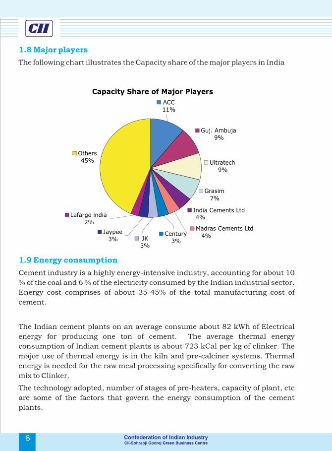
1.8 Major players
1.9 Energy consumption
The following chart illustrates the Capacity share of the major players in India
Cement industry is a highly energy-intensive industry, accounting for about 10
% of the coal and 6 % of the electricity consumed by the Indian industrial sector.
Energy cost comprises of about 35-45% of the total manufacturing cost of
cement.
The Indian cement plants on an average consume about 82 kWh of Electrical
energy for producing one ton of cement. The average thermal energy
consumption of Indian cement plants is about 723 kCal per kg of clinker. The
major use of thermal energy is in the kiln and pre-calciner systems. Thermal
energy is needed for the raw meal processing specifically for converting the raw
mix to Clinker.
The technology adopted, number of stages of pre-heaters, capacity of plant, etc
are some of the factors that govern the energy consumption of the cement
plants.
Capacity Share of Major Players
Guj. Ambuja 9%
Ultratech 9%
Grasim 7%
India Cements Ltd
4%
Others 45%
Madras Cements Ltd 4%
Century
3%
JK 3%
Jaypee 3%
Lafarge india 2%
ACC
11%
8
1.10 Need for Waste Heat Recovery systems in Indian cement
industry
1.10.1 Captive power in Cement industry
1.10.2 Waste heat recovery an alternate Source of Captive Power
generation
Captive Power refers to generation of power of its own, by the cement
manufacturing facility for its internal consumption exclusively. Majority of
cement plants operate with 100% captive power generation to avoid higher grid
costs and to power shortages and power failures.
Coal is primarily used as a fuel as oil and gas are not economical in India. In
some cases, power produced from wind farms are also used in addition to coal
based captive power plant.
Major reasons for plants going for captive power could be any or all of the
following reasons:
lUninterrupted power supply for their operations
lReliable source of power
lBetter quality of power supply
lReduced energy costs
On an average, the Indian cement plant requires power of 9 Billion kWh per year.
The coal needed for generating this much amount of power accounts to 15
Million Tons per year. To meet out the required coal quantity, the industry
spends about Rs 55 Billion each year.
In order to bring down the cost towards energy, several cost reduction
techniques such as using of pet coke and low grade coal, optimization of Indian
coal with imported coals are being practiced.
9

Waste heat recovery is now emerging as an excellent addition to existing captive
power generation. Other than reducing energy cost significantly, it can also be a
reliable source of power. The concept of waste heat recovery is slowly picking up
across the country.
Waste heat recovery offers several advantages to the Indian cement industry,
some of them being as follows:
lTo reduce fuel consumption, which in turn reduces fuel cost significantly
lTo simultaneously meet the demand for electricity and heat in a most cost-
effective manner
lTo bring down the specific energy consumption of the plant significantly
lTo bring about best energy efficient practice in the plant
lTo provide economic competitive advantage in the market
lTo mitigate the emission of Green house gases which are affecting the
environment adversely
1.10.3 Advantages of Waste Heat Recovery systems
10
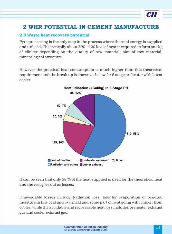
2 WHR POTENTIAL IN CEMENT MANUFACTURE
Pyro processing is the only step in the process where thermal energy is supplied
and utilised. Theoretically about 390 - 420 kcal of heat is required to form one kg
of clinker depending on the quality of raw material, size of raw material,
mineralogical structure.
However the practical heat consumption is much higher than this theoretical
requirement and the break up is shown as below for 6 stage preheater with latest
cooler.
It can be seen that only 58 % of the heat supplied is used for the theoretical heat
and the rest goes out as losses.
Unavoidable losses include Radiation loss, loss for evaporation of residual
moisture in fine coal and raw meal and some part of heat going with clinker from
cooler, while the avoidable and recoverable heat loss includes preheater exhaust
gas and cooler exhaust gas.
2.0 Waste heat recovery potential
Heat utlisation (kCal/kg) in 6 Stage PH
410, 58%
145, 20%
25, 3%
50, 7%
85, 12%
heat of reaction preheater exhasust clinker
Radiation and others cooler exhaust
11
Waste heat recovery is now emerging as an excellent addition to existing captive
power generation. Other than reducing energy cost significantly, it can also be a
reliable source of power. The concept of waste heat recovery is slowly picking up
across the country.
Waste heat recovery offers several advantages to the Indian cement industry,
some of them being as follows:
lTo reduce fuel consumption, which in turn reduces fuel cost significantly
lTo simultaneously meet the demand for electricity and heat in a most cost-
effective manner
lTo bring down the specific energy consumption of the plant significantly
lTo bring about best energy efficient practice in the plant
lTo provide economic competitive advantage in the market
lTo mitigate the emission of Green house gases which are affecting the
environment adversely
1.10.3 Advantages of Waste Heat Recovery systems
10
2 WHR POTENTIAL IN CEMENT MANUFACTURE
Pyro processing is the only step in the process where thermal energy is supplied
and utilised. Theoretically about 390 - 420 kcal of heat is required to form one kg
of clinker depending on the quality of raw material, size of raw material,
mineralogical structure.
However the practical heat consumption is much higher than this theoretical
requirement and the break up is shown as below for 6 stage preheater with latest
cooler.
It can be seen that only 58 % of the heat supplied is used for the theoretical heat
and the rest goes out as losses.
Unavoidable losses include Radiation loss, loss for evaporation of residual
moisture in fine coal and raw meal and some part of heat going with clinker from
cooler, while the avoidable and recoverable heat loss includes preheater exhaust
gas and cooler exhaust gas.
2.0 Waste heat recovery potential
Heat utlisation (kCal/kg) in 6 Stage PH
410, 58%
145, 20%
25, 3%
50, 7%
85, 12%
heat of reaction preheater exhasust clinker
Radiation and others cooler exhaust
11

The heat availability in the preheater exhaust is a function of the preheater gas
volume (depends on amount of excess air used for combustion, infiltration in to
the circuit, specific heat consumption and type of fuel), gas temperature
(depends on the heat transfer that is happening in the preheater i.e. number of
stages / cyclones in the preheater, dust content), dust content in the pre heater
gas (depends on the efficiency of the top stage cyclone).
The heat recovery potential in a cement plant will get subject to the
following:
lMoisture content in the limestone i.e., heat requirement for raw mill
lChanges in the number of stages / cyclones
lChange in the efficiency of top stage cyclone
lChange in excess air
lChange in the infiltration air level
The number of preheater stages in a cement plant has a significant bearing on
the overall thermal energy consumption and waste heat recovery potential.
Higher the number of stages; better is the thermal energy consumption and
lower would be the WHR potential.
The typical value of heat availability in the preheater exhaust gas for 1.0 MTPA
cement plant (with similar raw material moisture levels and clinker cooler) is
graphically represented in the figure
Heat availability in the preheater
exhaust gas
190
165
140
23.8 20.6 17.5
4 stage 5 stage 6 stage
kcal / kg clinker Mkcal / hr @ 1 MTPA
12
Selection on number of preheater stages is decided based on one or many of the
factors such as heat requirement for coal mill & raw mill, efficiency of cooler,
restriction on the preheater tower height, etc.
Another area of waste heat availability is cooler exhaust where excess air from
cooler is mostly vented into the atmosphere.
The basic function of the cooler is to recover the heat from the hot clinker
discharged from the kiln so that it can be handled by the subsequent
equipments and does not cause any hindrance to further processing that is
cement grinding. Rapid cooling also improves the quality of clinker and its
grindability.
Waste heat recovery potential depends on the type / generation cooler installed
and the utilisation of cooler gas for cement mill / raw mill & coal mill.
Fig Heat availability in the cooler exhaust gas
13.3 11.2 9.4
110
7590
1st generation
Cooler
2nd generation
Cooler
3rd generation
Cooler
kcal / kg clinker Mkcal / hr @ 1 MMTPA
13

2.1 Technical barriers in utilizing waste heat
2.1.1 Moisture content in raw material
2.1.2 Heat requirement for raw mill
Limestone deposits according to its origin will have moisture content of varying
from 2 % to 15 %. All the three types of rocks namely Ignititious, metamorphic &
sedimentary deposits are available in India.
Lime stone deposits in coastal region such as Junagadh in Gujarat or those
areas which has got converted from sea to land like Ariyalur belt of Trichirappalli
are of primarily sedimentary origin and have moisture content more than 8 %
even in hot summer. The moisture level increases with depth and rainy season.
Stone deposits of Gulburga belt of Karnataka, Yerraguntla or Nalgonda of Andra
Pradesh and Kota of Rajastan have practically moisture content less than 2 %
with maximum level of 5 % in rainy season. Their well developed crystalline
structure (or Non Amorphous form) does not allow absorption of moisture even
in heavy rain.
As discussed earlier, the quantity of moisture present in the kiln feed (entering
the preheater) influences the specific heat consumption and kiln production
rate to a large extent. This restricts the moisture content to less than 1 % in the
kiln feed. Drying of raw material is done along with grinding by utilising pre
heater hot gas / cooler hot gas as the heat source.
Theoretically about 540 kcal is required to evaporate or remove one kg of
moisture (or water) from raw meal / limestone. However practically VRM's
(Vertical Roller Mills) requires 900 to 1100 kcal of heat per kg of moisture and
Ball mills required about 750 to 850 kcal of heat / kg of moisture due to loss in
mill outlet gas, radiation loss, ingress of false air etc.
14
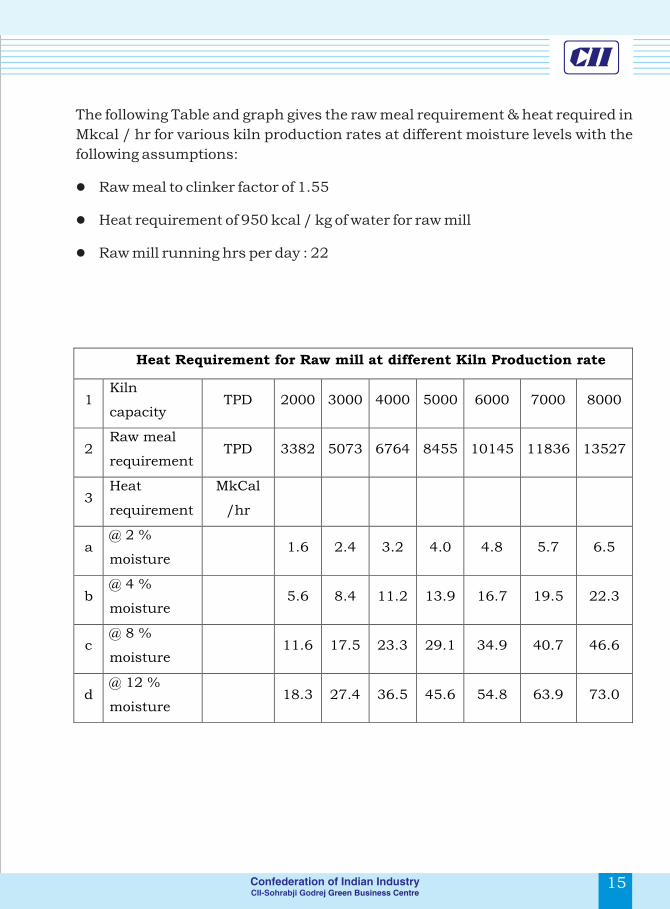
The following Table and graph gives the raw meal requirement & heat required in
Mkcal / hr for various kiln production rates at different moisture levels with the
following assumptions:
lRaw meal to clinker factor of 1.55
lHeat requirement of 950 kcal / kg of water for raw mill
lRaw mill running hrs per day : 22
Heat Requirement for Raw mill at different Kiln Production rate
1Kiln
capacity
TPD
2000
3000
4000
5000
6000
7000 8000
2Raw meal
requirement
TPD
3382
5073
6764
8455
10145
11836 13527
3Heat
requirement
MkCal
/hr
a@ 2 %
moisture
1.6
2.4
3.2
4.0
4.8
5.7 6.5
b@ 4 %
moisture
5.6
8.4
11.2
13.9
16.7
19.5 22.3
c@ 8 %
moisture
11.6
17.5
23.3
29.1
34.9
40.7 46.6
d@ 12 %
moisture18.3 27.4 36.5 45.6 54.8 63.9 73.0
15
2.1 Technical barriers in utilizing waste heat
2.1.1 Moisture content in raw material
2.1.2 Heat requirement for raw mill
Limestone deposits according to its origin will have moisture content of varying
from 2 % to 15 %. All the three types of rocks namely Ignititious, metamorphic &
sedimentary deposits are available in India.
Lime stone deposits in coastal region such as Junagadh in Gujarat or those
areas which has got converted from sea to land like Ariyalur belt of Trichirappalli
are of primarily sedimentary origin and have moisture content more than 8 %
even in hot summer. The moisture level increases with depth and rainy season.
Stone deposits of Gulburga belt of Karnataka, Yerraguntla or Nalgonda of Andra
Pradesh and Kota of Rajastan have practically moisture content less than 2 %
with maximum level of 5 % in rainy season. Their well developed crystalline
structure (or Non Amorphous form) does not allow absorption of moisture even
in heavy rain.
As discussed earlier, the quantity of moisture present in the kiln feed (entering
the preheater) influences the specific heat consumption and kiln production
rate to a large extent. This restricts the moisture content to less than 1 % in the
kiln feed. Drying of raw material is done along with grinding by utilising pre
heater hot gas / cooler hot gas as the heat source.
Theoretically about 540 kcal is required to evaporate or remove one kg of
moisture (or water) from raw meal / limestone. However practically VRM's
(Vertical Roller Mills) requires 900 to 1100 kcal of heat per kg of moisture and
Ball mills required about 750 to 850 kcal of heat / kg of moisture due to loss in
mill outlet gas, radiation loss, ingress of false air etc.
14
The following Table and graph gives the raw meal requirement & heat required in
Mkcal / hr for various kiln production rates at different moisture levels with the
following assumptions:
lRaw meal to clinker factor of 1.55
lHeat requirement of 950 kcal / kg of water for raw mill
lRaw mill running hrs per day : 22
Heat Requirement for Raw mill at different Kiln Production rate
1Kiln
capacity
TPD
2000
3000
4000
5000
6000
7000 8000
2Raw meal
requirement
TPD
3382
5073
6764
8455
10145
11836 13527
3Heat
requirement
MkCal
/hr
a@ 2 %
moisture
1.6
2.4
3.2
4.0
4.8
5.7 6.5
b@ 4 %
moisture
5.6
8.4
11.2
13.9
16.7
19.5 22.3
c@ 8 %
moisture
11.6
17.5
23.3
29.1
34.9
40.7 46.6
d@ 12 %
moisture18.3 27.4 36.5 45.6 54.8 63.9 73.0
15
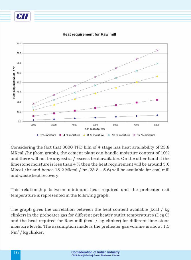
Considering the fact that 3000 TPD kiln of 4 stage has heat availability of 23.8
MKcal /hr (from graph), the cement plant can handle moisture content of 10%
and there will not be any extra / excess heat available. On the other hand if the
limestone moisture is less than 4 % then the heat requirement will be around 5.6
Mkcal /hr and hence 18.2 Mkcal / hr (23.8 – 5.6) will be available for coal mill
and waste heat recovery.
This relationship between minimum heat required and the preheater exit
temperature is represented in the following graph.
The graph gives the correlation between the heat content available (kcal / kg
clinker) in the preheater gas for different preheater outlet temperatures (Deg C)
and the heat required for Raw mill (kcal / kg clinker) for different lime stone
moisture levels. The assumption made is the preheater gas volume is about 1.5 3
Nm / kg clinker.
Heat requirement for Raw mill
0.0
10.0
20.0
30.0
40.0
50.0
60.0
70.0
80.0
2000 3000 4000 5000 6000 7000 8000
Kiln capacity, TPD
He
at
req
uir
ed
Mk
ca
l / h
r
2% moisture 4 % moisture 8 % moisture 10 % moisture 12 % moisture
16
Notes :
11. 260 - To be read as preheater exit gas temperature 260 Degree
Centigrade.
22. 140 – To be read as heat content available in the preheater gas in kcal /
kg clinker
33. 33 - To be read as heat requirement for raw mill @ 2 % moisture level in
kcal / kg clinker
The intersecting point (Point A) at 190 kcal / kg is the maximum point at about
340 DegC and 10% moisture. From this curve the following conclusions can be
made:
- If the operating conditions are falling under this region of vertical lines it
means that waste heat is available for recovery
- If the operating conditions are falling under this region of horizontal
lines it means that waste heat is not at all available and we need to provide extra
heat in addition to heat in preheater gas to raw mill.
A
Heat requirement Vs Availability
2193
333
673
1033
1403
1783
3201, 173
2
3001, 162
2 3601, 194
2340
1, 184
2
2801, 151
2
2601, 140
2
3801, 205
2400
1, 216
2
0
50
100
150
200
250
2 4 6 8 10 12 14 16
% Moisture level
He
at
co
nte
nt
in k
ca
l / k
g c
lin
ke
r
0
50
100
150
200
250
Limestone moisture & heat PH exit gas temperature & heat
17
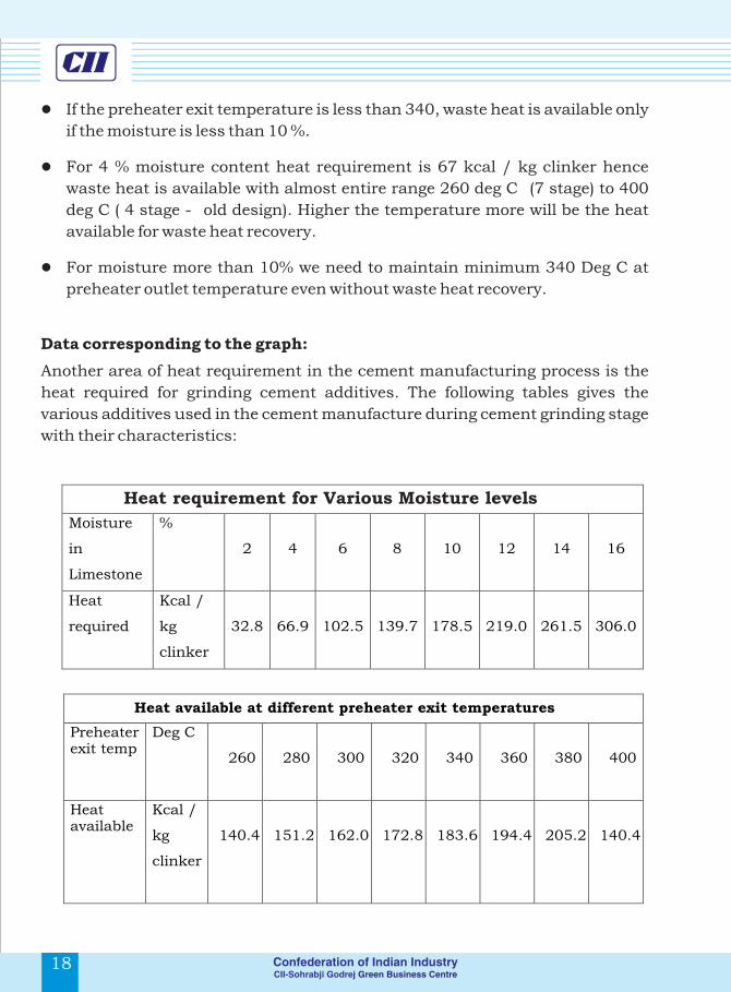
lIf the preheater exit temperature is less than 340, waste heat is available only
if the moisture is less than 10 %.
lFor 4 % moisture content heat requirement is 67 kcal / kg clinker hence
waste heat is available with almost entire range 260 deg C (7 stage) to 400
deg C ( 4 stage - old design). Higher the temperature more will be the heat
available for waste heat recovery.
lFor moisture more than 10% we need to maintain minimum 340 Deg C at
preheater outlet temperature even without waste heat recovery.
Data corresponding to the graph:
Another area of heat requirement in the cement manufacturing process is the
heat required for grinding cement additives. The following tables gives the
various additives used in the cement manufacture during cement grinding stage
with their characteristics:
Heat requirement for Various Moisture levels
Moisture
in
Limestone
%
2
4
6
8
10
12
14
16
Heat
required
Kcal /
kg
clinker
32.8 66.9 102.5 139.7 178.5 219.0 261.5 306.0
Heat available at different preheater exit temperatures
Preheater exit temp
Deg C
260
280
300
320
340
360
380
400
Heat available
Kcal /
kg
clinker
140.4
151.2
162.0
172.8
183.6
194.4
205.2
140.4
18
Hence it can be concluded that moisture level in the limestone deposit play a
major role in installing WHR technology by affecting the heat availability in the
preheater gas.
Another area of heat requirement in the cement manufacturing process is the
heat required for grinding cement additives. The following tables gives the
various additives used in the cement manufacture during cement grinding stage
with their characteristics:
2.1.3 Heat requirement for Cement Additives:
Characteristics of Cement Additives (other than Limestone)
Sl no
Material
% of
addition in
cement
% moisture
level
Heat
requirement
1 Gypsum 3- 5 %
A Chemical 8 - 20 Met from
grinding &
Clinker heat
B Salt pan 5 –
8
C Mineral 3 – 10 2 Fly ash
15-35 %
A Dry fly ash
<2.0 %
Not needed
B Wet fly ash
15.0 – 30.0 %
Extra Heat
required
3 Slag
35-65%
<12%
Extra Heat
required
19

It is evident from the table that the plants which are using the cement additives
such as wet fly ash and slag necessarily need heat for removing the moisture as
follows:
lFor Wet fly ash 95 kcal of heat is needed for every kg of cement considering
30 % wet fly ash addition & 25 % moisture in fly ash & evaporation heat of
950 kcal / kg water
lFor slag 65 kcal of heat is needed for every kg of cement considering 50 % wet
fly ash addition & 12 % moisture in fly ash & evaporation heat 950 kcal / kg
water
In most of the cement plants cooler vent air is used for this application and coal
fired / HSD fired hot air generator is also used.
Heat transfer is a function of both quantity of hot fluid and temperature
difference between the two fluids entering the Waste Heat Recovery Boiler or any
heat transfer equipment.
Q á M , ?T
Where,
Q is the rate of heat transfer in kcal /hr or kJ / hr
3M is the quantity of hot fluid, kg /hr or Nm /hr
?T is the temperature difference between the two fluids
The improved design characteristics of preheater with effective heat transfer
have resulted in the reduction of exit gas temperature. As discussed already,
temperature available in the 5 stage preheater varies between 290 to 320 deg C
depending on capacity utilization, operating efficiency, dust concentration.
With the available technology in Waste Heat Recovery such as Rankine, Organic
Rankine (more details of WHR technologies are highlighted in chapter 5 of this
report), recovery of heat up to temperatures of 240 Deg C and 200 Deg C
respectively is possible in the preheater section.
2.1.4 Quality / grade of heat:
20 21
The variation in the preheater exit temperature would be generally within +/- 5
deg C during normal running as the other process parameters like oxygen
content, kiln feed are maintained constant.
Cooler exit temperatures, on the other hand, will vary ± 20 Deg C and the
temperature range is about 280 to 350 deg C. This heat content also varies
greatly as it is affected by Clinker dust carry over, clinker bed thickness, clinker
quality which does not remain constant.
The graph shows the recovery of heat from various technologies for the same
preheater outlet temperature of 316 Deg C (5 stages). Cooler exit gas is
considered as the preheating source in combination with the preheater waste
heat recovery boiler and hence 33 % heat recovery is considered for cooler air for
all the systems.
Most the clinker manufacturing units in India have 2 and more kilns in the same
location or site to meet the clinker demand. It may be noted that though the heat
availability in individual kiln / cooler may be less, the total heat availability in
the locating including all the kilns may work out a sizable quantity to work out
waste heat recovery potential.
Temperature profile and Heat Recovery
33
68
37
24
50
100
150
200
250
300
350
400
Rankine Organic Kalina Cooler
Te
mp
era
ture
De
g C
0
10
20
30
40
50
60
70
80
% H
ea
t R
ec
ov
ery
WHRB outlet PH exit temp % Heat Recovery
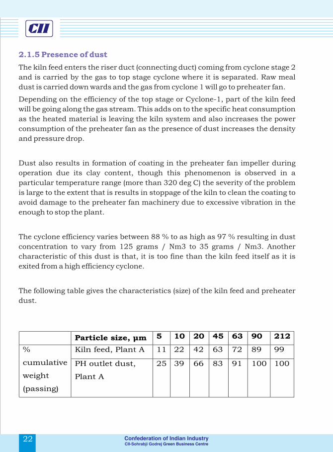
2.1.5 Presence of dust
The kiln feed enters the riser duct (connecting duct) coming from cyclone stage 2
and is carried by the gas to top stage cyclone where it is separated. Raw meal
dust is carried down wards and the gas from cyclone 1 will go to preheater fan.
Depending on the efficiency of the top stage or Cyclone-1, part of the kiln feed
will be going along the gas stream. This adds on to the specific heat consumption
as the heated material is leaving the kiln system and also increases the power
consumption of the preheater fan as the presence of dust increases the density
and pressure drop.
Dust also results in formation of coating in the preheater fan impeller during
operation due its clay content, though this phenomenon is observed in a
particular temperature range (more than 320 deg C) the severity of the problem
is large to the extent that is results in stoppage of the kiln to clean the coating to
avoid damage to the preheater fan machinery due to excessive vibration in the
enough to stop the plant.
The cyclone efficiency varies between 88 % to as high as 97 % resulting in dust
concentration to vary from 125 grams / Nm3 to 35 grams / Nm3. Another
characteristic of this dust is that, it is too fine than the kiln feed itself as it is
exited from a high efficiency cyclone.
The following table gives the characteristics (size) of the kiln feed and preheater
dust.
Particle size, µm 5 10 20 45 63 90 212
%
cumulative
weight
(passing)
Kiln feed, Plant A 11 22 42 63 72 89 99
PH outlet dust,
Plant A
25 39 66 83 91 100 100
22 23
Influence of dust in waste heat recovery
lPresence of dust will affect the heat transfer rate by forming coating over the
heat transfer areas in the Waste Heat recovery Boiler which in turn will affect
the efficiency of the cycle.
lPresence of dust can result in abrasion there by failure of tubes / heat
transfer equipment
lDust may form coating / blockage
Problem of dust can be handled by
lImproving the efficiency of the top stage cyclone in the case of preheater
lReducing the aeration velocity at the top of clinker bed in the case of cooler by
increasing the grate area or maintaining optimum cooler loading
lInstalling pre expansion chambers which will help to remove the bigger size
particles
lImproving the distribution of the gas inside the Waste Heat Recovery Boiler
(WHRB) to maintain uniform dust concentration and gas velocity and to
avoid excessive wear in any particular location due to turbulence
lCarefully designing the WHRB such that the gas velocity is within acceptable
range
Typically cement manufacturing process with dry technology does not require
any water directly for the process except the case that water is used for reducing
the gas temperature in the preheater side (if the heat is not used for raw mill /
coal mill) in the gas conditioning tower (GCT) and in the cooler & cement mill to
control the exit temperature of the gas stream.
Water is used for cooling purpose – mechanical parts like bearings etc., and dust
suppression and domestic usage. Typically for a 1.0 MTPA plant fresh water
requirement is about 300 to 400 m3 /day depending on the hardness of water,
climate and process as mentioned earlier excluding the captive power plants
installed in the units.
2.1.6 Water Availability for waste heat recovery

Majority of the Indian cement plants have their own coal based captive power
plants to meet the power demand of the cement process as mentioned earlier
require water to the tune of 4 – 6 m3 / hr / MW if water cooled condenser is used.
In the areas where water scarcity is prevailing or cost of water is high plants have
installed air cooled condenser which consumes only 0.3 to 1.0 m3/ hr / MW
with little drop in power generation capacity.
Waste heat recovery power plant with Rankine cycle will also be requiring
similar volumes of water. Hence the additional water requirement can be
handled by the existing set up or the plants can adopt air cooled condenser as
the alternate option when availability of water becomes a criteria.
Locating of WHRB systems near the preheater area could be one of the
challenging factors that may arise while considering recovery for old plants.
Preheater side WHRB will be under heavy suction (about 450 to 600 mm WC
below atmosphere pressure) and it will be better to have the WHR boiler near to
the preheater tower to avoid the false air ingress into the system and to reduce
the auxiliary / additional power consumption that may arise due to additional
length.
Excellent demand prevailing throughout the year has tightened the shut down
time / Maintenance time available for the kiln section in the Indian Cement
industry. Most of the Indian Cement plants have the kiln running hrs more than
8000 hrs per annum and availability as high as 93 % even with 100 -120 %
capacity utilization.
Any hook up of WHR system with the plant has to be done within 15 days of
annual shut down which calls for exhaustive planning and execution,
requirement of additional resources such as machinery etc.
2.1.7 Lay out constraint & down time for hook up
24 25
3 WASTE HEAT RECOVERY TECHNOLOGIES FOR
CEMENT INDUSTRY
3.0 Types of WHR technologies
3.1 Rankine Cycle
The following are the types of WHR technologies available / used by cement
plants for generating power from waste heat sources such as hot gases from the
clinker cooler, the pre-heater exhaust and DG exhaust.
Rankine cycle is a thermodynamic cycle which converts heat into work (power in
this case). The heat is supplied externally to vaporize the working fluid (water) in
the boiler into high pressure steam which expands in the turbine to produce
power by rotating it. The expanded vapor is condensed to low pressure liquid in
the condenser and is recycled back to the boiler for continuing the cycle.
The waste heat recovery (WHR) system, effectively utilize the available waste
heat from exit gases of pre-heater and clinker cooler. The WHR system consists
of Suspension pre-heater (SP) boiler, Air Quenching Chamber (AQC) boiler,
steam turbine generator, distributed control system (DCS), water-circulation
system and dust-removal system etc. The figure below demonstrates the
working of Rankine cycle
4
1
1
2
3
Source: Kawasaki technology for WHR
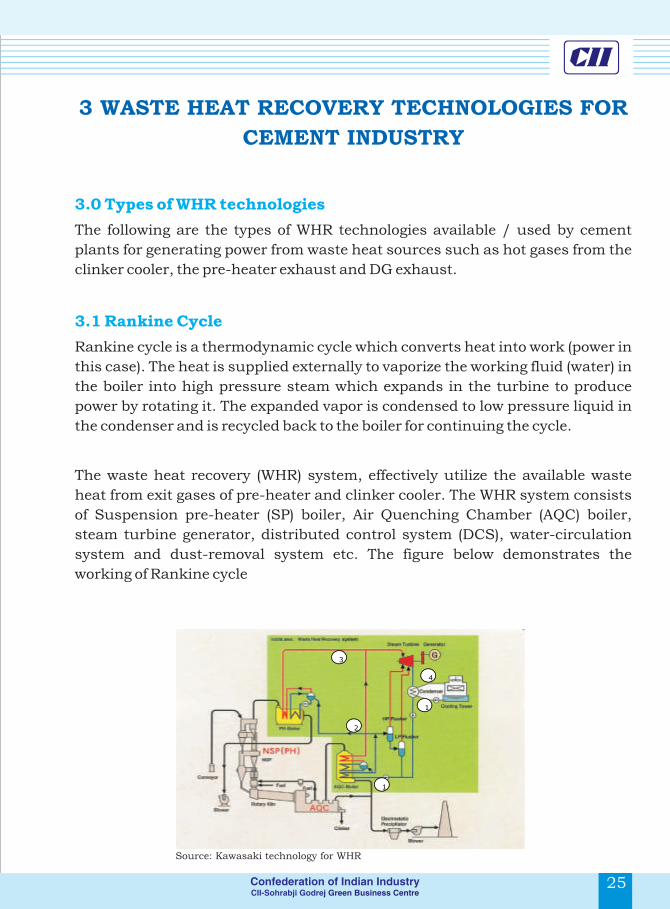

3.1.1 Working Principle
Process 1-2: The working fluid (i.e. water) is pumped from low to high pressure,
as the fluid is a liquid at this stage the pump requires little input energy.
Process 2-3: The high pressure liquid enters into AQC & SP boiler where it is
heated at constant pressure by using waste hot flue gas from clinker cooler and
pre-heater respectively to become a dry saturated vapour.
Process 3-4: The dry saturated vapour expands through a turbine, generating
power. This decreases the temperature and pressure of the vapour, and some
condensation occurs.
Process 4-1: The wet vapour then enters a condenser where it is condensed at a
constant pressure and temperature to become a saturated liquid. The pressure
and temperature of the condenser is fixed by the temperature of the cooling coils
as the fluid is undergoing a phase-change.
The Chart below exemplifies the Entropy diagram of Rankine cycle
Heat from waste
flue gas Qin
26 27
3.1.2 Features of Rankine Cycle system
The following are the features of Rankine cycle system for WHR
applications:
lAt the temperature profiles available in cement industry for WHR, these
systems would be operating at lower pressures
lAmong the various WHR technologies available, the power generation in
this system is low
lLesser heat recovery
lLow cost of installation
lCycle is proven and easy to operate
lHas several installations all over the world
l
The ORC uses a high molecular mass organic fluid. It recovers heat from even
low temperature sources. Due to this, it finds its applications in cement
industries, geothermal, solar ponds, etc. Heat available in the low temperature
gas of the clinker cooler exhaust can be recovered effectively by installing waste
heat Power plant based on ORC.
This cycle is an environmentally affable and is well suited to work with lower
temperatures to generate electricity on a continuous basis without interfering
with the clinker production process. The low temperature heat is converted into
useful work, which in-turn converted into electricity.
The ORC power plant consists of following cycles/circuits
lClinker cooling gas exhaust cycle
lWaste heat heater with thermal oil circuit
lPentane circuit
lAir condensing cycle
3.2 Organic Rankine Cycle (ORC)

The diagram below illustrates Working of the ORC system
Clinker cooling exhaust air Cycle: In this system, the atmospheric air is drawn
by the fans and is passed into the cooler for cooling the clinker. Heat exchange
takes place between atmospheric air and the hot clinker. Part of the air is used
for combustion of fuel in the kiln and excess air is vented into the atmosphere
after dust removal in an Electro static precipitator. The waste heat available in
this exhaust air is tapped in the Waste Heat Oil Heater (WHOH). The WHOH is a
conventional shell and tube heat exchanger. The hot air passes through bundles
of tubes consisting of low pressure thermal oil and transfers the heat to the oil.
Waste heat heater with thermal oil circuit: Due to heat exchange in WHOH
the temperature of thermal oil increases approximately from 1200C to 2700C.
This hot thermal oil is pumped to Pentane circuit and transfers the heat to
pentane.
Pentane circuit: The pentane circuit consists of Pentane Vaporizer, Pre-heater,
Turbine and Generator. The Pentane is heated from 550C to 1600C in
Evaporator & Pre-heater by exchanging heat with thermal oil.
3.2.1 Working Principle
Source: Ultra tech – 4MW – CDM – PDD using organic Rankine
Cycle Cementech – 2006 (ppt)
28 29
The high pressure Pentane vapor expands in turbine and the turbine in turn
drives the conventional AC Generator and generates Power. The Pentane from
the turbine is cooled in the Air Condensing System and re-circulated to pentane
vaporizer.
lORC uses low temperature waste heat available in clinker cooler effectively to
generate electricity
lHigh cycle efficiency
lZero water consumption for running the ORC, where air condensing is used
lVery high turbine efficiency (up to 85 percent)
lLow mechanical stress of the turbine, due to the low peripheral speed
lLow RPM of the turbine allowing the direct drive of the electric generator
without reduction gear
lNo erosion of blades, due to the absence of moisture in the vapor nozzles
lLong life
lMan power required is very less
The Kalina cycle was developed by Dr. Alex Kalina as a means of improving the
overall efficiency of combined cycle plants. The main benefit of the Kalina cycle is
that the heat addition to the process happens at variable and very low
temperatures. The temperature range required for the boiling of the ammonia-
water mixture in the Kalina process is 900C - 1000C minimum.
The main components of Kalina Cycle include a vapor turbine-generator,
evaporator, separator, condenser, recuperator exchangers and feed pump. The
working fluid is an ammonia-water mixture. In this mixture 82% is ammonia by
weight and rest is water.
3.2.2 Advantages of ORC system
3.3.1 Components
3.3 Kalina Cycle

The conspicuous efficiency advantage characteristic of the Kalina cycle is
realized from the heat exchange processes of the heat acquisition in the
evaporator and the heat rejection in the condenser. Additional efficiency is
achieved by the recuperator exchangers.
These gains are made possible by the variable boiling and condensing
characteristics of the ammonia-water mixture working fluid as it varies in
concentration at different points in the cycle.
The diagram below gives the schematic layout of the Kalina cycle
Starting at the outlet of the water-cooled condenser, the cycle working fluid is an
82% ammonia-water saturated liquid mixture at 5.4 bar and 12.4ºC. This
stream is pumped to a high pressure by the feed pump. The feed stream is
preheated in the low temperature (LT) and high-temperature (HT) recuperators
to 68ºC before entering the evaporator.
3.3.2 Working principle of the Kalina cycle
Source: Notes from the North: a Report on the Debut Year of the 2 MW Kalina Cycle® Geothermal Power Plant
in Húsavík, Iceland
30 31
In the evaporator, the working fluid is heated to 121ºC against a design brine
temperature of 124ºC. The ammonia-water is partially vaporized to a quality of
75 percent (75% vapor, 25% liquid). This mixed-phase fluid is sent to the
separator where the vapor component (high in ammonia) is separated from the
liquid component (low in ammonia).
The high-pressure rich saturated vapor from the separator drives the turbine as
the vapor rapidly expands and cools to a low-temperature, low-pressure
exhaust. The lean saturated liquid from the separator is cooled in the HT
recuperator where the sensible heat energy in this stream is used to preheat the
feed stream to the evaporator. The flow of this fluid is controlled by a level control
valve which maintains the liquid level in the separator. This liquid flow is then
directed to the inlet of the LT recuperator where it combines with the rich vapor
exhaust from the turbine. This liquid stream is sprayed into the exhaust vapor
stream, and the two streams unite to reform the basic fluid mixture of 82%. The
temperature of the liquid stream from the HT recuperator is 48ºC, and vapor
stream from the turbine is 60ºC.
These two streams, now as a mixed-phase fluid, are cooled in the LT recuperator
where the latent and sensible heat energy is used to preheat the feed stream. As
this fluid cools, some of the vapor stream from the turbine condenses. The liquid
that exits the LT recuperator is collected in a drain tank while the remaining
vapor goes directly to the condenser. At this point, the vapor has high ammonia
content, while the liquid in the drain tank has low ammonia content. The
temperature of both the vapor and liquid streams is 38ºC.
The liquid in the drain tank is pumped up to the inlet of the condenser to be
sprayed into the vapor stream. Spraying this lean liquid into a rich vapor aids
the condensation of the vapor by absorption process. The process is repeated in
a closed loop arrangement.

3.4 Performance of WHR units
Performance of WHR plants depends upon the following parameters
lFlow rate of flue gas (waste heat source)
lInlet temperature of the flue gas into the WHR system
lConcentration of dust in the gas
lLimitation in the outlet temperature of the gas from WHR system
(Requirement of heat for raw material to remove moisture)
lVariation in the quantity and inlet temperature of the flue gas due to process
fluctuations
lFailure of the running equipments
lBreakdown in the kiln section
lHook up time for the WHR system after starting the kiln
lDepends upon the operation and maintenance of the WHR system
lAvailability of the skilled workers
32 33
4 WHR INSTALLATIONS IN INDIA
4.1 Installation / Technology adopted
There are only few cement industries in India with waste heat recovery
technology for power generation. The following are the cement plants using the
WHR technology
1. India cements, Vishnupuram
2. JK cements, Nimbahera
3. KCP cements, Macherla
4. Shree cements, Beawar
5. Ultra tech cement (APCW), Tadipatri
The India Cements Ltd (ICL) has one of its units located at Vishnupuram,
Wadapally, Nalgonda District in Andhra Pradesh. The plant has 2 kiln lines of
capacities for producing 1800 & 5200 TPD. The plant also has a captive power
generation capacity of 16.0 MW diesel generators for standby.
ICL has installed for the first time in the country, a 7.7 MW WHR power plant
based on “Rankine Cycle” to utilize waste heat available in the clinker cooler
and pre-heater.
The Kawasaki heavy industries, Japan are the waste heat recovery supplier for
the plant. The project was partly funded from the New Energy Industrial
Development Organization (NEDO) of the Government of Japan and was
envisaged as a Model Project for waste heat recovery in the Indian cement
industry. The temperature of the waste heat gas coming out from the pre-heater
& clinker cooler is 350 0C & 360 0C respectively.
The technology encompasses two 15 bar waste heat recovery boilers of
28 TPH and 14 TPH capacities. The steam generated from these boilers is passed
to a 7.7 MW turbine generator with the resultant electricity fed to the cement
plant. The boilers are installed at the pre-heater exhaust (PH boiler) and at the
cooler exhaust from the kiln (AQC boiler). The boilers and turbine are
manufactured by Kawasaki of Japan.
4.1.1 The India Cements Ltd, Vishnupuram:

The PH boiler is a forced circulation
type boiler with a capacity of 28
TPH. The exhaust gas of the pre-
heaters are 350oC and once cooled
in the boiler exit at 220oC and are
then used in raw material drying.
Due to the high dust content of the
pre-heater gases and their adhesive
properties a hammering device is
installed in the boiler to remove the
dust that adheres to the boiler
surfaces and improve heat
exchange. The AQC boiler utilizes
gases from the cooler attached to
the kiln; these gases enter the boiler at 360oC. These gases typically have a high
content of clinker dust and therefore a pre-dust collector is introduced before
the gases enter the boiler.
JK Cement Ltd has its manufacturing facility located at Nimbahera, Chittorgarh
District, Rajasthan. The facility commenced its operations in 1974 and has a
current capacity of 2.8 MTPA. Three kilns are in operation producing clinker at
1200, 1800 & 4800 TPD.
To effectively utilize the waste heat of the exit gases from pre-heater, clinker
cooler and diesel generators, the plant team has installed a waste heat recovery
captive power plant consisting of WHR boilers, steam turbine and generator. In
the plant there are 6 WHR boilers (4 for the pre-heater exit gas, 1 for clinker
cooler and 1 for DG exit gas) and 13.2 MW steam turbine generator.
Waste heat recovery system by utilizing pre-heater exit gases
The average temperature of the exit gases from the pre-heater is around 3600C
and it would reduce to 220 0C at the outlet of the WHR boiler. The WHR boiler
would be installed between the outlet of pre-heater top cyclone and the inlet of
pre-heater Induced Draft (I.D) fan.
4.1.2 JK Cement, Nimbahera
34 35
The boiler installed in pre-heater line is designed to have enough heat transfer
surface by the arrangement of number of tubes which are provided with a forced
de-dusting equipment to avoid coating trouble of tubes due to high dust
concentration in the pre-heater exit gases.
Waste heat recovery system by utilizing AQC exit gases
The temperature of the exit gases from the clinker cooler is expected to be
around 300 0C which would reduce to 80 0C at the outlet of the boiler. The boiler
would be installed at the outlet of the AQC exit gas line and recovers the heat
from the cooler exit gas before releasing into atmosphere. Specially designed
finned tubes are adopted as heat exchanger tubes for the boiler which is
compact in size.
Waste heat recovery system by utilizing diesel generator exit gases
The WHR boiler would be installed at the outlet of diesel generator exit gas
system and recovers the heat from the exit gases before the release to the
atmosphere. Specially designed finned tubes are adopted as heat exchanger
tubes for the boiler. Considering the efficiency of boiler, the exit gases from DG
sets are induced into boiler by I.D. fan, installed in the downstream of the boiler.
No dust is contained in the exit gases but soot blowers with steam jet are
installed to clean the tubes periodically.
KCP cements are located in Macherla, Guntur district, Andhra Pradesh. The
plant is having 1 kiln line of capacity for producing clinker at 1800 TPD.
The plant is having captive power generation capacity of which run on diesel
generators. But the captive power generation is used only when the grid power
fails/emergency.
The plant is producing 2.35 MW power by using waste heat available in the
clinker cooler and pre-heater using “Rankine Cycle” for the power generation
with the waste heat available in the clinker cooler and pre-heater.
4.1.3 KCP cements, Macherla

The system was supplied by M/s. Transparent Energy Systems pvt. Ltd. The
temperature of the waste heat gas coming out from the pre-heater & clinker 0 0
cooler is 335 C & 300 C respectively.
The hot gases from clinker and pre-heater are passed through the waste heat
recovery boiler (WHRB1 & WHRB2) respectively. Water is circulated into the
WHRB. Latent heat from the hot gas is transferred to the water and is converted
to steam. The steam is expanded in the turbine and then it is condensed and the
condensed water is passed through the WHRG and the process repeats.
Shree Cement Ltd (SCL) has installed a waste heat recovery system in its Unit-1
at Beawar to recover the waste heat from the pre-heater exit gases, currently
being dissipated into the atmosphere, for steam generation. SCL has integrated
the waste heat recovery system with its captive power plant and the steam
generated in waste heat recovery is utilized for pre-heating the feed water in the
LP & HP heater of existing power plant.
Waste heat recovery system generates steam of 27.6 TPH at a temperature of
375 0C and pressure of 27 kg/cm2. This steam is utilized in the captive power
plant for feed water preheating.
With and without this waste heat recovery system, the difference in power
output from the captive power plant is about 5-6 MW. The fuel saving from this
project is anticipated at over 20000 tons per annum and carbon dioxide
emission reduction would be over 76000 tons per annum.
Ultratech Cement Ltd, Tadipatri is the first plant in India to install “Organic
Rankine Cycle” technology based Waste Heat Recovery project. The advantages
of Organic Rankine Cycle system are:
lHigh vapour turbine efficiency at low speed
lCondensing near atmospheric pressure
4.1.4 Shree Cement Ltd, Beawar
4.1.5 Ultratech cement (Andhra Pradesh cement works), Tadipatri:
36 37
lSmaller size air cooled condenser
lMoisture free turbine expansion
This system was installed to recover
the waste heat available in the
clinker cooler. The plant is producing
4 MW power by using waste heat
available in the clinker cooler.
Waste gas
Clinker Cooler Heat Source
Clinker Cooler Waste Gas
Thermal Oil Circuit
Heat Boiler Waste Heat Recovery
ORC-Equipment Power Generation
Air Condenser Cooling - Process
Pentane-Circuit Cooling-Circuit
Cycle Diagram of Power Generation From Clinker Cooler Waste Gas

There were two agencies involved in this project. Waste heat recovery unit was
supplied by Transparent Energy Systems, Pune and Energy Converter was
supplied by ORMAT Systems Limited, Israel.
The temperature of the cooling gas coming out from the electro static 0
Precipitator is at 320 C and the flow rate is 505 T/hr.
The high pressure Pentane vapor expands in the two stage turbine and the
turbine in turn drives the conventional 6.6 kV AC Generator and generates
Power. The Pentane from the turbine is cooled in the Air Condensing System.
The power plant is generating 21.8 million units per annum and is consumed in
plant itself.
Waste Heat Recovery Unit Input Parameters (Design):
lMass Flow rate of gas : 485 Tons / Hr
lVolumetric Flow : 375,500 Nm3/ Hr
lInlet temperature of Gas : 320 °C
lOutlet temperature of gas : 150 °C
lMax. Dust loading : 90 mg / Nm3
lAve. Dust particle size : 45 Microns
lAir pressure after ESP : -30 mm WC
The total investment required for the project was Rs 310 Million.
38 39
4.2 Challenges faced by cement plants installing WHR systems
4.3 Technical & Financial barriers in Operation
lSignificant In house Engineering requirement
lWHR - Vendor identification in India
lExecution by in house contracts
lInterfacing between OEC & WHR system
lLocation of unit to minimize distances – layout considerations
lHook up during Plant shutdown
lPresence of dust in flue gas
lHot gas availability & Load factor
lAdaptability of existing equipment
lFalse air ingress and addition power consumption
lNon availability of Indigenous suppliers & Service providers
lNon availability of funds and lack of financial support

5 BARRIERS IN ADOPTING WHR SYSTEMS IN
INDIAN CEMENT INDUSTRY
The concept of WHR in Indian cement industry has been under discussion over
the last several years. Various barriers were evaluated and the cement industry
today is reasonably aware of the benefits and cautions to be taken up for
successful implementation of WHR systems. This understanding has been
through various initiatives – detailed discussions with technology providers,
case studies of installations globally and nationally, and a thorough
understanding of existing cement operation and integration of WHR systems.
Adoption of WHR system in existing cement manufacturing facility poses
multiple barriers and the implementation team should be equipped to overcome
these carriers. Some of the barriers are as under:
lDust content of the exit gases from the cement manufacturing process, is
high with typical values of 30 to 100 g/Nm3.
lThe preheater dust is sticky in nature, forms coating over the surface of the
heat transfer tubes in the boiler. This affects the heat transfer and reduces
the power generated.
lThe Clinker dust in the cooler exit air is highly abrasive in nature, erodes the
heat transfer area affecting the operation of the system.
The problems due to dust is handled in the following ways:
i. Preheater dust can be largely reduced by installing high efficiency
cyclone at the top stage or improving the efficiency of the existing
cyclones.
ii. Altering the design of the heat transfer surfaces (vertical tubes in
place of horizontal tubes) to avoid coating.
5.1 Technical barriers in Operation & the possible solutions
5.1.1 Presence of dust in flue gas
40 41
iii. Installation of dust separation chamber like ESP incase of cooler dust.
iv. Considering adequate margin of safety to take care of erosion and
abrasion due to dust
v. Installation of dust removal or cleaning mechanisms like tumbling
hammer.
Uninterrupted supply of waste gases from clinkerization process at consistent
quality (sufficient temperature) is needed for trouble free operation of waste heat
recovery system.
lAs the Waste heat in exhaust gases from the clinkerization process is used in
drying of raw material and coal, availability of Waste heat to the WHR is
affected due to variation in moisture levels in raw material and coal.
lVariations in the process, changes in production level affect the quality &
quantity of flue gas resulting in variation of the power generation in WHR.
lIn general it takes about 4 – 24 hours to achieve the rated production level in
the kiln system after any planned or unplanned shutdown depending on the
nature and time of shut down. This inurns affect the quantity of waste heat
from the kiln and hence the performance of the system.
Variations in the performance of the WHR system due the above problems can
be minimized to certain extent by taking due care while designing the system
with respect to moisture level. Improved automation and skilled manpower can
help to achieve maximum power generation in line with the variations in the
process parameters.
Installation of WHR system in the cooler and preheater side will call for capacity
enhancement or additional load on the existing equipments such as preheater
fan, cooler vent fan etc to handle WHR system without affecting the present
production levels. This is due to the additional pressure drop, false air ingress
due to installation of WHR systems.
5.1.2 Hot gas availability & Load factor
5.1.3 Adaptability of existing equipment

If adequate margin is not available, these equipments are to be considered for
replacement with revised technical specification and the economics have to be
taken care.
The preheater boiler is operating under negative suction created by the
preheater fan for the passage of combustion gas produced in the kiln and
calciner. This negative pressure can result in atmospheric air ingression, if
holes are present.
This atmospheric air ingression (known as false air) reduces the heat content,
quantity of steam generated and increases the power consumption of fan.
Therefore, air infiltration into the boilers will affect economics of WHR by
increasing its operation costs.
Installation of additional equipments and pressure drop increases the specific
power consumption of the process and the same has to be taken into account for
economics of power generation.
Standard operating procedures with close monitoring of false air ingression,
auxiliary power consumption and power consumption for clinker will eliminate
the above problems.
Limited number of suppliers and non-availability of Indigenous suppliers /
service providers for installation, operation, maintenance of WHR system is one
of the major challenging factors affecting the installation or adoption of the
technology. Creating the awareness about the market potential and the overall
benefits, support from the Government & financial agencies can attract the
indigenous supplier towards this market.
5.1.4 False air ingress and additional power consumption
5.1.5 Non-availability of Indigenous suppliers & Service providers
42 43
5.2 Financial barriers
One of the major financial barriers as far as adoption of WHR systems is
concerned is the large capital requirement and unattractive funding
mechanisms. India today has 5 WHR systems installed and running as on date.
Almost all the funding for these projects came from the company's internal
resources. Companies which are cash-rich are in a position to adopt WHR
systems today.
Another major driver for the installation of WHR systems in Indian cement
industry is the benefit the company can tap from the international carbon
markets through the Clean Development Mechanism (CDM) route. All the
projects implemented till date have registered / in the process of registering for
CDM benefits. Low IRR compared to the benchmark IRR values has been one of
the major factors substantiating financial barrier for WHR based CDM projects.

6 ESTIMATION OF WASTE HEAT RECOVERY
POTENTIAL
6.0 Basic data & Assumptions:
1. Kiln capacity : 3000 tonnes per day
2. No of stages in the preheater : 5
3. Preheater exit gas details
3a. Volume (m ) : 1.5 Nm /kg clinker PH
b. Specific heat capacity(CP ): 0.36 kcal / g / Deg Ck PH
c. Temperature T : 316 Deg C PH1
4. Cooler exit gas details
3a. Volume (m ): 1.0 Nm /kg clinkerC
b. Specific heat capacity C : 0.317 kcal / kg / Deg CPC
c. Temperature T : 300 Deg CC
5. Limestone moisture content LM : 2 %
6. Raw mill running hrs : 22 hrs /day
7. Kiln running days per annum : 335 days
8. Heat transfer efficiency of WHR boiler - EFF : 85 %WHR
9. Heat transfer efficiency of AQC boiler – EFF : 85 %AQC
10. TG system efficiency EFF : 33 %TG
11. Specific heat consumption : 700 kcal / kg clinker
12. Raw coal moisture : 15 %
13. Raw meal to clinker factor : 1.55
44 45
14. Heat requirement for moisture in raw mill & Coal mill: 950 kcal / kg water
15. Calorific value of fine coal used in the : 5000 kcal / kg coal
16. Coal mill running hrs per day : 20
17. PH gas temperature at WHRB outlet T : 240 Deg CPH2
18. Cooler exit temperature at AQC boiler outlet T : 120 deg CC2
1. Heat available in the preheater gas :
Q : m * CP * T PH PH PH PH1
: 1.5 * 0.36 * 316
: 170.6 kcal / kg clinker
2. Heat required for Raw mill
a. Raw mill capacity : 3000 * 1.55 * 24 / 22
: 5073 TPD
: 211 TPH
: 1.688 kg / kg clinker
b. Moisture in raw mill : [211 * 100 / (100 - 2)] – 211
: 4.3 TPH
: 34.4 kg / MT clinker
c. Heat requirement for raw mill : 34.4 * 950 / 1000
: 32.7 kcal / kg clinker
: 33 kcal / kg clinker
3. Heat requirement for coal mill
a. Coal requirement
Specific coal consumption : 700 / 5000
: 0.14 kg coal / kg clinker
Coal mill capacity : 0.14 * 125 * 24 / 20
: 21 TPH
6.1 Calculations

4. Moisture evoparation in coal mill : {21 * 100 /(100 – 15)}– 21
: 3.7 TPH
: 30 kg / MT clinker
5. Heat requirement for raw mill : 30 * 950 / 1000
: 28.5 kcal / kg clinker
: 29 kcal / kg clinker
Excess heat available in the preheater:
Heat available in the PH gas minus heat required for Coal mill & raw mill
Excess heat available (preheater) : 170.6 – (29 + 33)
: 108.6 kcal / kg clinker
6. Heat available in the Cooler exit gas :
Q : m * C * T C C PC C
: 1.0 * 0.317 * 300
: 95.1 kcal / kg clinker
7. Total excess or waste heat available :
Extra heat available in the preheater + cooler
: 108.6 + 95.1
: 203.7 kcal / kg clinker
8. Heat recoverable in Preheater side Boiler
Q : m * C * (T -T ) WHRB PH PPH PH1 PH2
: 1.5 * 0.36 * ( 316 – 240 )
: 41.0 kcal / kg clinker
9. Heat recoverable in Cooler side Boiler
Q : m * C * (T - T ) AQC C C c1 c2
: 1.0 * 0.317 * ( 300 – 120 )
: 57.0 kcal / kg clinker
46 47
Heat available to steam for power generation :
: Q * EFF + Q * EFFWHRB WHR AQC AQC
: 41.0 * 0.85 + 57.0 * 0.85
: 83.3 kcal / kg clinker
10. Power generation possible :
Heat available in the steam
TG efficiency : 83.3 * 0.33
: 27.5 kcal / kg clinker
: 0.03197 kWh / kg Clinker
: 31.97 kWh / MT of clinker
: 4.0 MW
11. Water requirement for Water cooled condenser :
Heat to be removed in the condenser :
: 83.3 * (100 – 33)/ (0.85*100)
: 66 kcal / kg clinkerMake up
Water requirement : 56 / 540
: 0.1222 kg water / kg clinker
: 15.3 TPH
: 3.8 MT /MW
7 MAJOR SUPPLIERS AND THEIR SYSTEMS
7.0 Suppliers of Rankine Cycle WHR systems
Kawasaki plant systems
Kobe Head Office
1-1 Higashikawasaki-cho 3-chome, Chuo-ku,
Kobe, Hyogo 650-8670, Japan
TEL 81-78-682-5200 FAX 81-78-682-5574
Tokyo Head Office
11-1 Minamisuna 2-chome, Koto-ku,
Tokyo 136-8588, Japan
TEL 81-3-3615-5200 / FAX 81-3-5690-3159
Transparent energy systems private limited
Pushpa Heights,1st Floor, Bibwewadi Corner,
PUNE-411 037. INDIA.
Tel no : 91-20-24211347, 24212390.
Fax : 91-20-24212533
E-mail :
Website:
Dalian East Energy Project corporation limited
Hangzhou Office
450, Zhongshan Beilu, Hangzhou – 310003, China
Tel: +86 571 850 66546
Fax: +86 571 851 00298
E-mail:
http://www.khi.co.jp
http://www.tespl.com
48 49
Dalian Office
Longwangtang, Lushan, Dalian 116044, China
Tel: +86 411 862 97331
Fax: +86 411 862 97254
Ormat Technologies, Inc
6225 Neil Road
Reno, Nevada 89511-1136
Tel.: (775) 356-9029
Fax: (775) 356-9039
e mail: ,
Siemens AG
Wittelsbacherplatz 2
D-80333 Munich, Germany
International (English): +49 (69) 797 6660;
Germany (German): +49 (800) 225 53 36
Mail ID:
[email protected] http://www.ormat.com/
http://w1.siemens.com/entry/cc/en/
7.1 Kalina Cycle Suppliers

50 51
8 REFERENCES
1. Basic data 2007, CMA
2. http://siadipp.nic.in/publicat/cement.htm
3. http://www.mapsofindia.com/
4. http:// www.ibef.org/-India Brand Equity Foundation
5. http://www.cmaindia.org/ -Cement Manufacturer's Association
6. Cement Statistics 2007, Cement Manufacturer's Association
7. Report from CRISIL for IBEF-The India Brand Equity Foundation is a public-private partnership between the Ministry of Commerce and Industry, Government of India and the Confederation of Indian Industry. The Foundation's primary objective is to build positive economic perceptions of India globally.
8. http:// www.asiansecurities.com/-Asian Markets Securities Private Ltd.;Mumbai
9. http://www.careratings.com/-Credit Analysis & Research Ltd..;Mumbai
10. Basic data 2007,Cement Manufacturer's Association
11. Company Toolkit for Energy Efficiency – www.geriap.org (Greenhouse gas emission reduction from industry in asia and the pacific)
12. Addressing Energy Security and Climate Change October, 2007- Bureau of Energy Efficiency and Climate Change October, 2007
13. http://fact.co.in/gypsum.html
http://sbmsalt.tradeindia.com/Exporters_Suppliers/Exporter17684.274191/Gypsum.html
9 CONCLUSION
The Indian cement industry is keen to adopt WHR systems in a big way. The
technical specialization within the Indian cement industry is advanced; the
plant operating team can overcome the technical barriers analyzed. The major
deterrent in faster adoption of WHR systems has been the financial barrier.
The potential for WHR in Indian cement industry is very high. In conclusion,
CII's estimates indicate that the waste heat recovery potential in Indian cement
industry is close to 415 MW while the installed capacity till date is only about 20
MW. This indicates the huge opportunity for adoption of waste heat recovery in
Indian cement industry.
The manual focuses on major WHR technologies successfully employed in the
world and India in particular.
a) Description of technology
b) WHR installations in Indian cement industry
c) Major suppliers and contact information
d) Major technical or operating problems incurred
i. To identify existing applications of WHR in India; successes and
problems.
ii. To identify barriers to deployment of WHR technologies; past,
current and future, including water requirement, and its impact
on the project both financial and technical.
e) Capital investment required (based on past installations in India)
We are sure that the Indian Cement plants will make use of the waste heat
available and install WHR systems. This will substantially reduce the operating
cost. CII looks forward for more and more installations of Waste Heat Recovery
system across Indian Cement industry.


For more details, kindly contact
About CII
About CII-Godrej GBC
About Asia-Pacific Partnership
The Confederation of Indian Industry (CII) works to create and sustain an environment conducive to the growth of industry in India, partnering industry and government alike through advisory and consultative processes.
CII is a non-government, not-for-profit, industry led and industry managed organisation, playing a proactive role in India's development process. Founded over 113 years ago, it is India's premier business association, with a direct membership of over 7500 organisations from the private as well as public sectors, including SMEs and MNCs, and an indirect membership of over 83,000 companies from around 380 national and regional sectoral associations.
CII catalyses change by working closely with government on policy issues, enhancing efficiency, competitiveness and expanding business opportunities for industry through a range of specialised services and global linkages. It also provides a platform for sectoral consensus building and networking. Major emphasis is laid on projecting a positive image of business, assisting industry to identify and execute corporate citizenship programmes. Partnerships with over 120 NGOs across the country carry forward our initiatives in integrated and inclusive development, which include health, education, livelihood, diversity management, skill development and water, to name a few.
Complementing this vision, CII's theme "India@75: The Emerging Agenda", reflects its aspirational role to facilitate the acceleration in India's transformation into an economically vital, technologically innovative, socially and ethically vibrant global leader by year 2022.
With 64 offices in India, 9 overseas in Australia, Austria, China, France, Germany, Japan, Singapore, UK, USA and institutional partnerships with 211 counterpart organisations in 87 countries, CII serves as a reference point for Indian industry and the international business community.
CII – Sohrabji Godrej Green Business Centre (CII – Godrej GBC), a division of Confederation of Indian Industry (CII) is India's premier developmental institution, offering advisory services to the industry on environmental aspects and works in the areas of Green Buildings, Energy Efficiency, Water Management, Renewable Energy, Green Business Incubation and Climate Change activities.
The Centre sensitises key stakeholders to embrace green practices and facilitates market transformation, paving way for India to become one of the global leaders in green businesses by 2015.
The Asia Pacific Partnership on Clean Development & Climate is an innovative new effort to accelerate the development and deployment of clean energy technologies. APP partners Australia, Canada, China, India, Japan, Republic of Korea and The United States have agreed to work together and with private sector partners to meet goals for energy security, national air pollution reduction, and climate change in ways that promote sustainable economic growth and poverty reduction.
The partners will also cooperate on the development, diffusion and deployment of longer-term transformational energy technologies that will promote economic growth while enabling significant reductions in green house gas intensities. The partnership will be consistent with and contribute to partners' efforts under the UNFCCC and will compliment, but not replace the Kyoto protocol.
“Foster GHG Emission Reduction Technologies in Indian Cement Industry” is an initiative of CII-Godrej GBC to carry out GHG emission inventorization in Indian Cement plants and explore & identify possible opportunities to reduce the same. This activity is supported and part funded by U.S Department of State as part of the Asia Pacific Partnership (APP) on Clean Development and Climate. This seminar is one of a number of public awareness programs planned as part of this project. For further details on this project, please get in touch with [email protected].
Survey No 64, Kothaguda Near HITEC City, Hyderabad - 500 084
Tel: +91 40 23112971-73 Fax: +91 40 23112837
www.greenbusinesscentre.org
P V Kiran Ananth