manual of soil laboratory testing vol. iii.pdf
TRANSCRIPT
78
Chapter 17
Test equipment
17.1 Introduction17.1.1 ScopeFor the purpose of this chapter, the equipment required for effective stress tests is divided into the following categories. Descriptions of those items in each category that are more commonly used are outlined in the sections indicated.
1. Cells or confi ning chambers in which specimens are mounted and tested (generally referred to as the ‘cell’); Section 17.2.
2. The means of applying regulated pressures to the specimens internally or externally (‘pressure systems’); Section 17.3.
3. Apparatus for applying axial force to the specimen (such as a ‘loading frame’); Section 17.4.
4. Mechanical and electronic measuring devices for determining the applied forces and pressures, and for measuring the resulting deformation and other changes im-posed on the specimen; Section 17.5.
5. Electronic systems for the capture, processing and storage of data; Section 17.6.6. Miscellaneous small accessories, tubing and fi ttings, materials and tools; Section 17.7.Reference is made in this chapter to a number of items which have been covered in Vol-
ume 2, especially those used for triaxial tests, and further details are given where necessary. The emphasis is on equipment for effective stress triaxial compression tests. Consolidation test equipment is listed for completeness, but is described in more detail in Chapter 22.
Guidance on preparing and checking test apparatus is given in Section 17.8. Outline notes on general laboratory practice, and the calibration of measuring devices, are covered in Chapter 18, with references to Volume 2 where appropriate.
17.1.2 Analogue and digital instrumentsIn many laboratories, measurements of load, pressure, displacement, etc., are made exclu-sively using electronic instrumentation, with data capture and storage by means of data log-gers and desktop or laptop computers. However, operators should also be familiar with test procedures and measurements using ‘conventional’ or analogue instruments in order to be fully conversant with the test procedures. Consequently, Section 17.5 describes both elec-tronic and conventional instruments, whereas Section 17.6 describes data logging equipment and procedures.

Test equipment
79
Electronic instrumentation offers a number of benefi ts.1. Readings are displayed directly in engineering units, needing no conversion
factors.2. Transducer outputs are recorded for subsequent analysis (particularly important
when a test is left unattended).3. Digital displays reduce the possibility of errors that can be made when reading
gauges.4. One display unit can monitor all the data from a test, or data from several tests.5. Progress of the test can be displayed graphically in real time.6. Computer processing of test data can be carried out automatically.7. Tests can be controlled by feedback from the computer.8. Alarms can be set to alert staff when limits of apparatus may be approaching.9. Non-linearity of transducers can be accommodated in some data loggers by multi-
point calibration.
Importance of calibrationThere is a tendency to accept digitally displayed readings without question as being au-thentic and accurate, but their accuracy is no greater than the accuracy with which the measuring devices were calibrated. This applies whether or not conversion factors and calibration corrections are built into the electronic circuitry. Calibration of electronic equipment is just as important as the calibration of traditional instruments and is ad-dressed in Chapter 18.
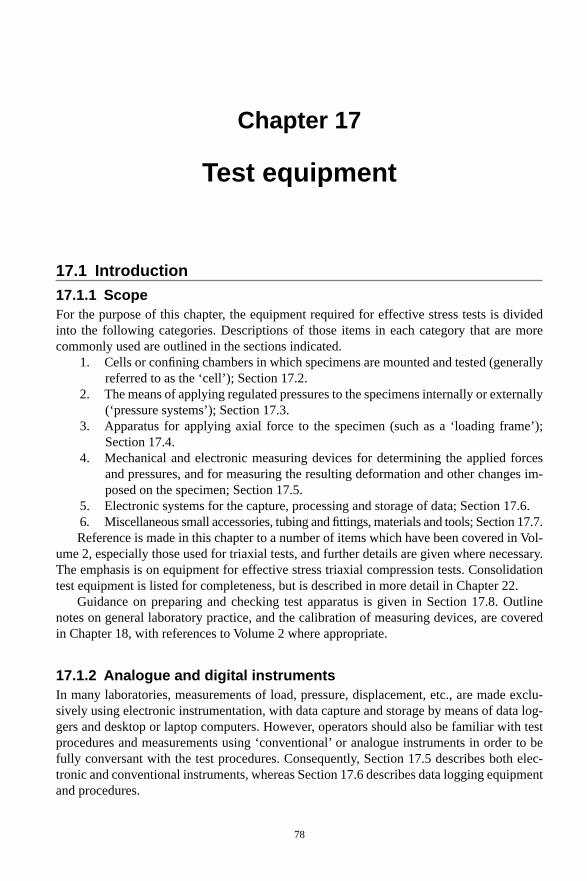
17.1.3 SymbolsThe test equipment and ancillary systems described in this book are generally in accordance with the requirements of BS 1377: 1990: Parts 6 and 8. They were derived from the appa-ratus originally developed by Professor A.W. Bishop at Imperial College, London (Bishop, 1960; Bishop and Henkel, 1962). Wherever possible, the letter symbols assigned to valves are consistent with those used by Bishop and Henkel (1962).
In the diagrams, certain items are represented by the symbols shown in Figure 17.1.
17.1.4 Defi nitionsSome of the terms used in electronic instruments are defi ned in the following.
A/D converter (ADC) Analogue to digital converter. Electronic device converting a con-tinuous electrical input to an equivalent digital output.
Autonomous data acquisition unit (ADU) A programmable interface unit between trans-ducers and microcomputer which can capture transducer signals at predetermined intervals and store the data for subsequent processing.
Amplifi er Electronic device for magnifying a current or voltage.Channel An electrical pathway, usually connected to a transducer.Data acquisition system A system for the gathering and treatment of information, usu-
ally measurements from transducers.Data logger Device for gathering and storing data, usually from transducers.Data processor Means of manipulating information.
Manual of Soil Laboratory Testing
80
Data storage Means of storing information.Digital display Visual means of displaying actual numerical values.Electronic instrumentation In this context, a measurement system based on electronic
components.Hardware All the electronic and mechanical components that make up a computer
system.Interface Means of allowing a computer to communicate with external devices.LSCT Linear strain conversion transducerLVDT Linear variable differential transformer. A device on which displacement trans-
ducers of high linearity are based.Notebook or netbook A portable laptop or minicomputer.Output signal Electrical value obtained from a measuring device.PC Personal computer.Peripheral A device such as a printer or disk drive which is external to the computer.Program A set of instructions to tell the computer to execute a sequence of tasks.Read-out Means of displaying measurements.Scanner A component, usually of a data logger, which sequentially takes readings from
a number of channels.Signal conditioning unit Device for accepting a range of electrical inputs and producing
electrical outputs within a common range.
Figure 17.1 Symbolic representation of common items of equipment
Test equipment
81
Software The programs required to operate the computer.Stabilised power supply Electrical supply which remains constant despite changing im-
posed load or electrical input.Strain gauge A system of resistances, bonded to or integral with a surface, whose resist-
ance changes with deformation of that surface.Transducer A device which converts a change in physical quantity to a corresponding
change in electrical output.Visual display unit (VDU) A screen on which instructions and data can be displayed in
words, numbers or in graphical form.
17.2 Test cells17.2.1 Types of cellThe pressure vessel in which a test specimen is mounted for carrying out various strength or compressibility tests is referred to as the ‘cell’. It may also be called the ‘pressure chamber’ or ‘chamber’, especially in the USA.
Several types of cells are used for different types of effective stress tests on soils, as follows.
1. Plain bearing piston-loading triaxial cells for carrying out strength tests on speci-mens subjected to a confi ning pressure, referred to as ‘standard’ triaxial cells. Sev-eral different sizes were referred to in Volume 2, Section 13.7.2.
2. Triaxial cells fi tted with linear ball bushings in the cell top to minimise piston fric-tion and maintain alignment, as used in the USA.
3. Special cells to facilitate tests in which no lateral yield is permitted (K0 cells).4. A special type of cell developed at Imperial College, London for a wide variety of
purposes, especially stress path tests (the Bishop–Wesley cell).5. Cells without a loading piston for triaxial consolidation tests (triaxial consolidation
cells).6. Consolidation cells using a hydraulic loading system (hydraulic consolidation cells
or Rowe cells), as developed at Manchester University, UK.The main features of standard cells, types (1) and (2), are described in Section 17.2.2,
and mention is made of cells of type (3) in Section 17.2.3. Cells of type (4) are more spe-cialised and details are not given here. Consolidation cells, types (5) and (6), are covered in Section 17.2.4, but hydraulic consolidation cells of different sizes are described in greater detail in Chapter 22.
17.2.2 Standard triaxial cellsGeneral featuresTriaxial cells and their necessary fi ttings for various types of effective stress tests are de-scribed in the following section. Special features relating to larger cells (i.e. for specimens of 100 mm diameter and upwards) are referred to separately.
Details of a typical cell are shown in cross-section in Figure 17.2. The main compo-nents are:
1. Cell base2. Cell body and top

Manual of Soil Laboratory Testing
82
3. Loading piston4. Loading caps (top and base).
Components(1) Cell baseThe base is machined from corrosion-resistant metal or a suffi ciently hard plastic material. Four outlet ports are normally required. The purpose of each outlet port, and the designation of the valve connected to it, are as follows (see Figures 17.2 and 17.3).
i. Connection to base pedestal for the pore pressure measuring device (the transducer mounting block) (valve a).
ii. Connection to sample top cap for the back pressure system for drainage and appli-cation of back pressure to the specimen (valve b).
iii. Cell chamber connection for fi lling, pressurising and emptying the cell (valve c).iv. Second connection to base pedestal for drainage, or infl ow of water in permeability
tests (valve d). This valve is not mandatory in BS 1377, but here it is assumed to be included. Its absence would require amendments to certain procedures.
Figure 17.2 Details of a typical triaxial cell (the oil fi ller plug is not normally fi tted to commercially available cells)

Test equipment
83
Some cells are fi tted with an additional port for providing a second connection to the top cap, denoted by x in Figure 17.3. The additional port allows fl ushing of water across the top to eliminate air.
Each outlet terminates at a screwed socket on the edge of the cell base, into which can be fi tted a valve, or a blanking plug if the line is not used. Each valve is connected to the appropriate pressure line. In addition, a valve is required on the side of the pore pressure transducer mounting block remote from valve a, between the block and the fl ushing system to which it is connected (valve a1). The valve designations a, a1, b, c, d given here are used consistently throughout this book. Details of suitable valves and other fi ttings are described in Section 17.7.2.
The cell chamber port (c) may be of a larger bore than the others to allow reasonably rapid fi lling and emptying of the cell. Ports (a), (b) and (d) leading to the base pedestal are of small bore in order to enclose the smallest practicable volume of water in the pore pressure measuring system (see Section 17.5.2).
The top surface of the pedestal may be either smooth, or machined with shallow radial and circular grooves. A grooved pedestal improves the drainage communication from the porous disc which is placed between the specimen and the small bore outlet, but a smooth surface makes for less likelihood of trapping air under the disc. If neither pore pressure measurement nor drainage is needed at the base, a solid Perspex or aluminium alloy disc is placed on the pedestal instead of a porous disc.
When a porous disc of high air entry value (see Section 17.7.3) is needed, a more posi-tive seal can be formed if the disc is of smaller diameter than the pedestal and bonded into a recess with epoxy resin. The arrangement for 38 mm diameter specimens is shown in Figure 17.4(a), and for large (e.g. 100 mm) diameter samples in Figure 17.4(b).
The base pedestal of some cells can be fi tted with adaptors which enable one cell to be used for specimens of several diameters. Care must be taken not to trap air, or excess water, between the adaptor components when setting up. For tests requiring accurate measurements
Figure 17.3 Triaxial cell base outlet ports. See text for details

Manual of Soil Laboratory Testing
84
of pore pressure it is better to use a cell with an integral base pedestal that is compatible with the specimen diameter without having to use adaptors.
The cylindrical side of the pedestal should be polished smooth and free from scratches and deformities to ensure a watertight seal with the rubber membrane. Old aluminium pedestals in particular are susceptible to corrosion and pitting makes effective sealing problematic.
The back pressure port from valve b leads to a gland in the cell base (Figure 17.2) which is connected by a length of small-bore nylon tubing to the specimen top loading cap (see (4) below). A similar arrangement is provided for a second top cap connection, if fi tted.
(2) Cell body and topSeveral types of cell body were described in Volume 2, Section 13.7.2, together with com-ments on their care and use.
A bracket fi tted to the cell top forms a seating for the stem of the strain dial indicator or transducer (Figure 17.2). The cell top is fi tted with an air bleed plug. A useful modifi cation is to drill and tap an additional hole for fi tting a valve which can be connected to a pressurised oil supply. This enables oil to be inserted into the cell (see below), and to be replenished during a test if necessary.
The cell body expands when pressurised, but this volume change can be allowed for by calibration against pressure (see Section 18.4.4).
(3) Loading pistonThe loading piston (also referred to as the ‘ram’ or ‘plunger’) is machined to a close toler-ance in the bush in the cell top. The piston should slide down freely under its own weight when the cell is empty, and should allow negligible leakage of fl uid from the cell when in use. For further details, see Volume 2, Section 13.7.2. For effective stress tests, which are usually of long duration, a layer of castor oil 10–15 mm thick should be inserted to fl oat on top of the water in the cell. This reduces both leakage past the piston and piston friction by
Figure 17.4 Triaxial cell base pedestals: (a) 38 mm diameter; (b) 100 mm diameter
Test equipment
85
providing lubrication. Measurement of leakage is described in Section 18.3.2, and the effect of piston friction is discussed in Section 18.4.5.
The piston is fi tted with a fi xed or adjustable collar to prevent it being forced out if the cell is pressurised when not in position in a load frame. A rubber O-ring on the collar forms a seal against leakage when in this position. Alternatively, an external bracket can be used as a piston restraint, but the strain dial bracket should not be used for this purpose unless designed for the job.
The lower end of the piston may have a coned recess, or may be fi tted with a hemispheri-cal end, depending on the design of the top loading cap (see below). The piston diameter should not be less than about one-sixth of the test specimen diameter.
Some cells used in the USA are fi tted with linear ball bushings to reduce piston friction.
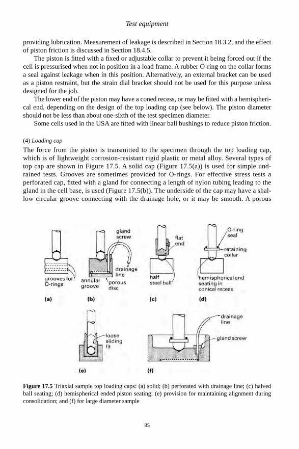
(4) Loading capThe force from the piston is transmitted to the specimen through the top loading cap, which is of lightweight corrosion-resistant rigid plastic or metal alloy. Several types of top cap are shown in Figure 17.5. A solid cap (Figure 17.5(a)) is used for simple und-rained tests. Grooves are sometimes provided for O-rings. For effective stress tests a perforated cap, fi tted with a gland for connecting a length of nylon tubing leading to the gland in the cell base, is used (Figure 17.5(b)). The underside of the cap may have a shal-low circular groove connecting with the drainage hole, or it may be smooth. A porous
Figure 17.5 Triaxial sample top loading caps: (a) solid; (b) perforated with drainage line; (c) halved ball seating; (d) hemispherical ended piston seating; (e) provision for maintaining alignment during consolidation; and (f) for large diameter sample
Manual of Soil Laboratory Testing
86
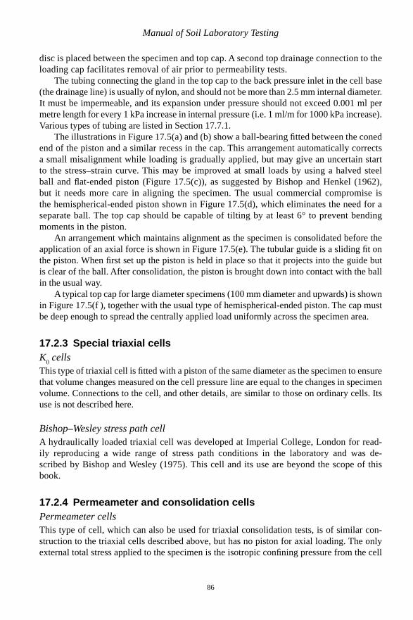
disc is placed between the specimen and top cap. A second top drainage connection to the loading cap facilitates removal of air prior to permeability tests.
The tubing connecting the gland in the top cap to the back pressure inlet in the cell base (the drainage line) is usually of nylon, and should not be more than 2.5 mm internal diameter. It must be impermeable, and its expansion under pressure should not exceed 0.001 ml per metre length for every 1 kPa increase in internal pressure (i.e. 1 ml/m for 1000 kPa increase). Various types of tubing are listed in Section 17.7.1.
The illustrations in Figure 17.5(a) and (b) show a ball-bearing fi tted between the coned end of the piston and a similar recess in the cap. This arrangement automatically corrects a small misalignment while loading is gradually applied, but may give an uncertain start to the stress–strain curve. This may be improved at small loads by using a halved steel ball and fl at-ended piston (Figure 17.5(c)), as suggested by Bishop and Henkel (1962), but it needs more care in aligning the specimen. The usual commercial compromise is the hemispherical-ended piston shown in Figure 17.5(d), which eliminates the need for a separate ball. The top cap should be capable of tilting by at least 6° to prevent bending moments in the piston.
An arrangement which maintains alignment as the specimen is consolidated before the application of an axial force is shown in Figure 17.5(e). The tubular guide is a sliding fi t on the piston. When fi rst set up the piston is held in place so that it projects into the guide but is clear of the ball. After consolidation, the piston is brought down into contact with the ball in the usual way.
A typical top cap for large diameter specimens (100 mm diameter and upwards) is shown in Figure 17.5(f ), together with the usual type of hemispherical-ended piston. The cap must be deep enough to spread the centrally applied load uniformly across the specimen area.
17.2.3 Special triaxial cellsK0 cellsThis type of triaxial cell is fi tted with a piston of the same diameter as the specimen to ensure that volume changes measured on the cell pressure line are equal to the changes in specimen volume. Connections to the cell, and other details, are similar to those on ordinary cells. Its use is not described here.
Bishop–Wesley stress path cellA hydraulically loaded triaxial cell was developed at Imperial College, London for read-ily reproducing a wide range of stress path conditions in the laboratory and was de-scribed by Bishop and Wesley (1975). This cell and its use are beyond the scope of this book.
17.2.4 Permeameter and consolidation cellsPermeameter cellsThis type of cell, which can also be used for triaxial consolidation tests, is of similar con-struction to the triaxial cells described above, but has no piston for axial loading. The only external total stress applied to the specimen is the isotropic confi ning pressure from the cell

Test equipment
87
fl uid. The cell accommodates specimens of 70 or 100 mm diameter, with heights of up to twice the diameter. It is sometimes referred to as a fl exible wall permeameter.
Base connection ports are similar to those provided in a normal cell, with two base ped-estal drainage ports. The top cap is also fi tted with two drainage ports to facilitate de-airing and fl ushing.
A modular system designed for performing multiple permeability tests simultaneously, using cells of this type, is shown in Figure 17.6.
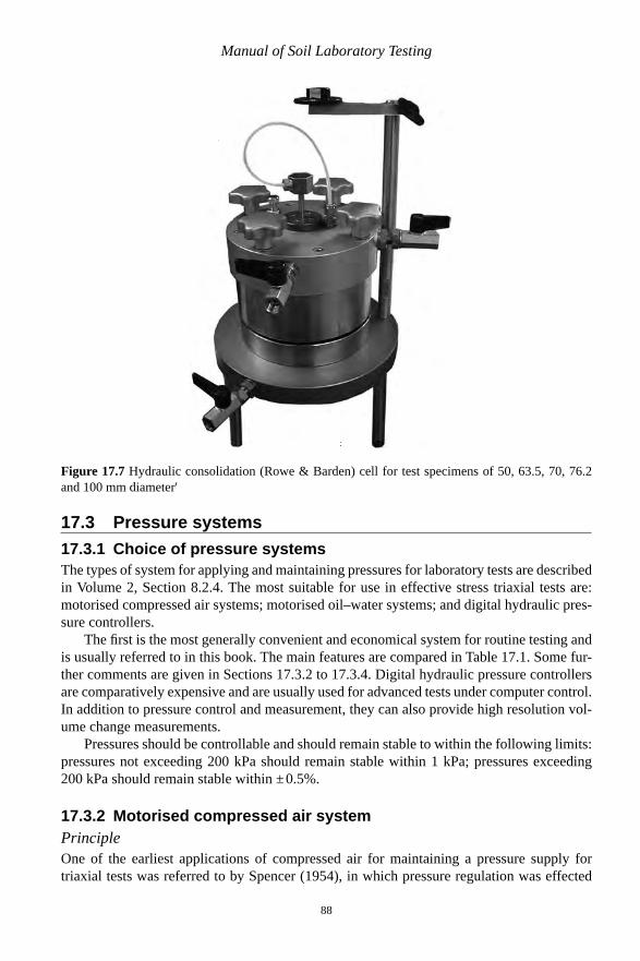
Hydraulic consolidation cellsHydraulically loaded consolidation cells (Rowe cells) are described in Chapter 22. Figure 17.7 shows a cell capable of testing specimens of up to 100 mm diameter which is supplied commercially in the UK. Larger diameter cells, up to 250 mm, are operated by a number of testing laboratories in the UK. The bodies of larger diameter cells can be stacked to double the height of the specimen and allow soils with larger maximum particle diam-eters to be tested. They are used for the determination of the consolidation properties of soils from tests in which pore pressures are measured, and back pressures applied if re-quired, in ways similar to those used in effective stress triaxial tests.
Figure 17.6 Modular system for multiple permeability tests in triaxial permeability cells
Manual of Soil Laboratory Testing
88
Figure 17.7 Hydraulic consolidation (Rowe & Barden) cell for test specimens of 50, 63.5, 70, 76.2 and 100 mm diameter'
17.3 Pressure systems17.3.1 Choice of pressure systemsThe types of system for applying and maintaining pressures for laboratory tests are described in Volume 2, Section 8.2.4. The most suitable for use in effective stress triaxial tests are: motorised compressed air systems; motorised oil–water systems; and digital hydraulic pres-sure controllers.
The fi rst is the most generally convenient and economical system for routine testing and is usually referred to in this book. The main features are compared in Table 17.1. Some fur-ther comments are given in Sections 17.3.2 to 17.3.4. Digital hydraulic pressure controllers are comparatively expensive and are usually used for advanced tests under computer control. In addition to pressure control and measurement, they can also provide high resolution vol-ume change measurements.
Pressures should be controllable and should remain stable to within the following limits: pressures not exceeding 200 kPa should remain stable within 1 kPa; pressures exceeding 200 kPa should remain stable within ± 0.5%.
17.3.2 Motorised compressed air systemPrincipleOne of the earliest applications of compressed air for maintaining a pressure supply for triaxial tests was referred to by Spencer (1954), in which pressure regulation was effected