manual - mutec
TRANSCRIPT

1
ManualREF10REF10 SE120


3
Content
Precautions 4
Warranty Regulations 5
Introduction
General Description 6
Features REF10 and REF10 SE120 6
Features REF10 SE120 6
Matching MUTEC Products 7
Accessories 7
Product Registration for Warranty and Support 7
Social Media 7
Installation
Shipping Contents 8
Placing the Device 8
Interface Connections 9
Control Elements and Terminals
Front Panel 10
Rear Panel 10
Operation
General System Operation 11
Recommendations for REF10 and REF10 SE120 11
Applications
Using the REF10 or REF10 SE120 With Other Products 12
10 MHz Compatible Products 13
Appendix
Changing the Line Voltage 16
Pin Assignment of the Terminals 16
Technical Data 16

REF 10
4
Precautions
General Instructions
To reduce the risk of fire or electrical shock, do not expose this device to rain or moisture, direct sunlight or excessive heat from sources such as radiators or spotlights There are no user-serviceable parts inside
Any repair and maintenance may only be carried out by qua-lified personnel authorized by MUTEC GmbH The device was designed for operation in a standard domestic environment Do NOT expose the unit and its accessories to rain, moisture, direct sunlight or excessive heat produced by heat sources such as radiators or spotlights! A free flow of air inside and in close proximity to the unit must always be ensured
Initial Operation
Prior to the initial operation of the device, the unit itself, its accessories and packaging must be inspected for any signs of physical damage that may have occurred during transit If the unit has been damaged mechanically or if liquids have been spilled inside the enclosure, the device may not be connected to the mains power or must be disconnected from the mains immediately! If the unit is damaged, please do NOT return it to MUTEC GmbH, but notify your dealer and the shipping company immediately Otherwise, any liability claims will not be granted
If the device is left in a low-temperature environment for a long time and is then moved to a room-temperature environ-ment, condensation may occur on the inside and the exterior of the device To avoid short-circuits and electric shocks, make sure to wait one or two hours before putting the device back into operation
Power Supply
The device contains a self-adapting, wide-range power supply supporting the majority of global standard line voltages within a range of 90-250 V, with no need for any user adjustments
Make sure that your line voltage source provides a supply vol-tage within the specified range In addition, make sure that the device is properly grounded via the local electric instal-lation Please use the enclosed power cable (see packaging) to connect the unit to the mains power Switch the unit off before you attempt to connect it to the mains Firstly, connect the power cord to the device, then to a standard 3-pin mains outlet To remove the power cord never pull on the cable but on the mains plug!
The unit must be grounded during operation! For information on the power input module wiring, refer to the »Wiring of connectors« section in the appendix Disconnect the device from the mains when not using it for an extended period!
Trademarks
MUTEC GmbH assumes no liability for any incorrect informa-tion provided in this manual Please note that all software/hardware product names are registered trademarks of their respective owners No part of this manual may be reproduced, copied or converted to a machine-readable form or electro-nic media without written permission by MUTEC GmbH We reserve the right to change or improve our products without further notice
© MUTEC GmbH 2020
This symbol, a flash of lightning inside a triangle, alerts you to the presence of non-insulated dan-gerous voltage inside the enclosure - voltage that may be sufficient to constitute a risk of shock
This symbol, an exclamation mark inside a triangle alerts you to important operating or safety instruc-tions in this manual
Declaration of Conformity
We herewith confirm that this product complies with the European Commission’s standards on electromagnetic compatibility
Interference emission:
EN 50081-1, 1992, Resistance to interference: EN 50082-1, 1992 Presupposed as operation condition is that all signal
outputs are connected with high-quality and well shielded cables

5
Warranty Regulations
§1 Warranty
MUTEC GmbH warrants the flawless performance of this pro-duct to the original buyer for a period of two (2) years from the date of purchase If any failure occurs within the specified warranty period that is caused by defects in material and/or workmanship, MUTEC GmbH shall either repair or replace the product free of charge within 90 days The customer is not entitled to claim an inspection of the device free of charge during the warranty period If the warranty claim proves to be justified, the product will be returned freight prepaid by MUTEC GmbH within Germany Outside Germany, the pro-duct will be returned with the additional international freight charges payable by the customer Warranty claims other than those indicated above are expressly excluded
§2 Warranty Transferability
This warranty is extended exclusively to the original buyer who purchased the product from a MUTEC GmbH specialized dealer or distributor, and is not transferable to anyone who may subsequently purchase this product No other person (re-tail dealer, distributor, etc ) shall be entitled to give any war-ranty promise on behalf of MUTEC GmbH
§3 Warranty Regulations
The return of the completed registration card, or online regis-tration on one of the websites specified below, is a condition of warranty Failing to register the device before returning it for repair will void the extended warranty
The serial number on the returned device must match the one stated on the registration card or entered during online regist-ration Otherwise, the device will be returned to the sender at the sender’s expense Any returned device must be accompa-nied by a detailed error description and a copy of the original sales receipt issued by a MUTEC dealer or distributor
The device must be returned free of shipping expenses and in the original package, if possible; otherwise, the sender has to provide comparably protective packaging The sender is fully responsible for any damage or loss of the product when ship-ping it to MUTEC GmbH
§4 Limitation of Warranty
Damages caused by the following conditions are not covered by this warranty:
• Damages caused by every kind of normal wear and tear (e g displays, LEDs, potentiometers, faders, switches,
buttons, connecting elements, printed labels, cover glas-ses, cover prints, and similar parts)
• Functional failure of the product caused by improper installation (please observe CMOS components handling instructions!), neglect or misuse of the product, e g failure to operate the unit in compliance with the instructions given in the user or service manuals
• Damage caused by any form of external mechanical impact or modification
• Damage caused by the user’s failure to connect and ope-rate the unit in compliance with local safety regulations
• Damage caused by force majeure (fire, explosion, flood, lightning, war, vandalism, etc )
• Consequential damages or defects in products from other manufacturers as well as any costs resulting from a loss of production
• Repairs carried out by personnel which is not authorized by MUTEC GmbH
§5 Repairs
To obtain warranty service, the customer must call or write to MUTEC GmbH before returning the unit All inquiries must be accompanied by a problem description and the original buyer’s invoice Devices shipped to MUTEC GmbH for repair without prior notice will be returned to the sender at the sen-der’s expense In case of a functional failure please contact:
MUTEC Gesellschaft für Systementwicklung und Komponentenvertrieb mbH Siekeweg 6–8, 12309 Berlin, Germany Phone: +49 (0)30 746880-0 Fax: +49 (0)30 746880-99 E-Mail: tecsupport@mutec-net com Web: www mutec-net com

REF 10
6
Introduction
General Description
Thank you very much for your purchase of the MUTEC REF10, respectively the REF10 SE120 an audiophile 10 MHz reference master clock generator
The REF10 is an audiophile reference master clock generating 10 MHz signals with ultra-low phase noise (i e jitter) to sig-nificantly improve digital playback systems As the conductor of your digital audio orchestra at home, the REF10 will inspire you with unheard-of clarity, graceful dynamics, and pure mu-sic It is also the most flexible, most compatible 10 MHz clock on the market allowing you to spend less time worrying about integration and leaving you with more hours to enjoy blissful playback
In contrast to so-called »atomic clocks«, clocks based on a ru-bidium or cesium normal, the REF10 as well as the REF10 SE120 are engineered around MUTEC's handcrafted, oven-controlled oscillators (OCXO) made in Germany, featuring significantly higher clock stability in the time domain relevant for audiophi-le digital audio performance Newly developed ultra-low noise clock distribution and amplification circuits based on sub-1 Hz optimized, lowest noise voltage sources transfer the reference signal to the unit's eight outputs with virtually no losses
As a result and unlike any other currently available reference generator the REF10 and REF10 SE120 fulfill both of the cri-tical requirements for an extraordinary audiophile reference master clock:
• Lowest possible phase noise for unmatched audio
• Highest clock precision for most accurate synchronization
The REF10 SE120 is a special version of the REF10 that we have further enhanced in terms of signal performance It out-performs the original REF10 in this regard considerably A clearly measurable advantage is the result of a special feature of the REF10 SE120: its much more elaborately manufactured and selected OCXO This oscillator is selected according to the strictest standards in test procedures lasting many hours with help of exceptionally precise and expensive measuring tech-nology The use of such an outstanding oscillator is responsible for the fact that the REF10 SE120 currently delivers - to our knowledge - the lowest phase noise, respectively jitter values in the industry This outstanding technical performance has a noticeable impact on the sonic audiophile result Precision, transparency, spatiality and dynamics of the musical presenta-tion reach an unprecedented level and will amaze you!
Features REF10 and REF10 SE120
• Audiophile 10 MHz reference generator with leading lowest phase noise
• Improves and enhances compatible DACs, audio re-clo-ckers, music servers and master clocks
• Engineered around a handcrafted, ultra-low phase noise OCXO made in Germany
• Revolutionary, sub-Hz optimized, lowest noise power supply for every circuit section
• Generates a very high slew-rate square wave signal for superior lock precision compared to the sine wave signals used by competing brands
• Provides simultaneous reference outputs with 50 and 75 Ω impedance for maximum compatibility with clocks and DACs by other manufacturers
• Eight galvanically isolated, individually switchable BNC clock outputs
• Highly efficient power line filtering
• Integrated, highest-quality international linear power supply
• Intuitive user interface with noble aesthetics
• Rack-mountable with optional mounting brackets for studio use (2U)
Features REF10 SE120
• Audiophile 10MHz reference master clock generator with ultimately-low phase noise of -120 dBc measured at 1 Hz offset from the carrier frequency of 10 MHz

7
Matching MUTEC Products
• MC3+ Smart Clock An audio re-clocker and master clock that provides low-jit-ter clock audio signal generation and aggressive audio re-clocking using MUTEC’s REVIVE technology
• MC-3+ Smart Clock USB As the successor of the MC3+ Smart Clock , the MC3+USB offers significantly improved audio performan-ce and an isolating USB interface for audio computers and music servers
• iClock & iClock dp iClock and iClock dp are both synchronizable, highest precision clock synthesizers for audio/video production studios and broadcast
Accessories
• MUTEC's PRIME SELECT line of 75 Ohms audio clock cab-les in various lengths, exclusively approved by the REF10, respectivels REF10 SE120 developer Ask your retailer for further details!
• MW-07/19: rack mount kit for installing the REF10 or REF10 SE120 in 19” racks (item no 8020-046)
Product Registration for Warranty and Support
We kindly ask you to register your MUTEC product through our website immediately after buying This ensures full war-ranty services over a period of three years after purchasing the product Additionally, we provide free technical support for all registered products We will also inform you about new products and product updates (you may opt-out at any time of course)
Please register your product at:
www mutec-net com > Service > Product Registration
Or for direct access type in the following URL into your browser:
http://www mutec-net com/produktregistrierung php?lng=en
Social Media
facebook com/mutecpro

REF 10
8
Installation
Shipping Contents
Your REF10, respectively REF10 SE120 was packaged carefully Nevertheless we recommend checking the contents directly af-ter opening the package:
1 x REF10 or REF10 SE120 1 x Power cable 1 x Manual
In the unexpected event that there are any visible damages or missing items, please refer to the chapter »Safety Instruc-tions« and »Warranty Regulations« for further details
Placing the Device
The unit should be set up as closely as possible to the devices to which it will be connected to avoid excessive cable lengths The four custom-designed case feet include a rubber ring pro-tecting the ground’s surface from being damaged and redu-cing any structure-borne vibrations interfering with the unit It is recommended to keep the device away from vibrating or mechanically moving devices in close proximity
The device can be mounted into a standard 19“ rack and will require 2U (rack units) Therefore, we offer an optional rack mounting kit called MW-07/19 This includes two rack bra-ckets which need to be screwed to each side of the device‘s case Before mounting the device into a 19“ rack, please un-screw the four rubber feet with a suitable screwdriver Install the device so that 1U of rack space is left open both above and below the device to allow for sufficient ventilation! For extra secure installation we further recommend an additional rack mounting plate that will prevent any long-term mechani-cal deformation of the enclosure
Attention
Before installing the unit the section Safety Instructions located at the beginning of this manual should be read carefully! Never expose the device and accessories to rain, moisture, direct sunlight, or excessive heat pro-duced by radiators, heaters, or spot lights! Sufficient air circulation in the proximity of the device must be ensured!
Interface Connections
There are two standards with respect to interfaces and cable termination for 10 MHz reference signals:
• 50 Ω impedance terminationThis standard can commonly be found among units by Japanese Hi-Fi manufacturers, and for measurement devices in laboratory applications
• 75 Ω impedance terminationThis termination is more common for devices used in recording, mixing and broadcast studio applications
For audiophile Hi-Fi and high-end consumer audio applications both standards are currently in use by different manufacturers For this reason, the REF10, respectively REF10 SE120 provides clock outputs with both 50 and 75 Ω termination that can be used simultaneously
Transferring clock signals with 50 Ω termination is typically done with coaxial cables according to the RG-58/U standard However, we recommend using cables manufactured to the RG-400/U or CLF200/HDF200 standards, because they are double-shielded and offer reduced attenuation in contrast to the RG-58/U norm Cables specified as CLF200/HDF200 further feature a stronger inner copper conductor
For clock signals with 75 Ω termination it is common to use coaxial cables specified by the RG-59/U and RG-598/U as well as RG-216/U sstandards
A wide range of coaxial cables with BNC connectors and the appropriate termination by specialized manufacturers are avai-lable at Hi-Fi retailers Depending on their price range they are manufactured using premium materials and will have superi-or transfer characteristics than the aforementioned standard cables
All interfaces of the devices in a given setup need to be pro-perly connected with each other Always ensure that the clock output of the REF10, respectively REF10 SE120 are connected to an appropriate input of the receiving device Make sure that the clock input of the receiving device has the correct inter-nal impedance termination This internal termination can so-metimes be adjusted via an external switch on the device or via a software setting We recommend double-checking the operating manual of any device that you are planning the REF10, respectively REF10 SE120 to be connected to A mis-matched termination of the system will cause losses in signal quality and clock precision!

9
We further recommend keeping the cable lengths as short as possible to minimize signal losses and interference Cables at 0 5 m, 1 m, or a maximum of 2 m length are ideal The longer the cable needs to be, the higher the quality should be to avoid excessive losses!
Useage of so-called BNC tee adaptersBNC tee adapters are often used to daisy-chain clock signals between several devices Usually this is necessary if the clock master does not provide a sufficient number of clock outputs Since the REF10, respectively REF10 SE120 generates excep-tionally low phase noise, i e highest quality signals, any ad-ditional elements in the signal path can have an attenuating effect that negatively affects the crucial slew rate of the sig-nal Consequently and considering that the REF10, respectively REF10 SE120 provides a total of eight clock outputs we advise against daisy-chaining 10 MHz clock signals
Any device that is supposed to be clocked by the REF10, res-pectively REF10 SE120 and benefit from its audiophile perfor-mance must be connected to a dedicated clock output!

REF 10
10
Control Elements and Terminals (equal for REF10 and REF10 SE120)
Front Panel
1) »POWER«This red LED illuminates when the device has been powered up First engage the rear panel power switch next to the mains terminal Always ensure the appropriate choice of line voltage »115 V / 230 V«! Then, depress the front panel power switch and the red LED will light up
2) »OUTPUT SELECT«This combined push button rotary encoder is used to select the individual outputs and to disengage or re-engage them
3) »LEDs 1 – 8«These eight white LEDs represent the eight rear panel clock outputs and reflect if the respective output has been turned on or off An illuminated LED means the output is active, i e on
4) »OSCILLATOR«This blue LED reflects the status of the oscillator heat-up pro-cess Upon powering the device up this LED will be flashing until the oscillator has reached its correct operating tempera-ture Once the temperature has been established, the LED will be permanently lit
Rear Panel
1) »50 Ω, Outputs 1 – 2«These two clock outputs are equipped with a 50 Ω terminati-on Use only BNC cables with the appropriate 50 Ω impedan-ce with these outputs
2) »75 Ω, Outputs 3 – 8«These six clock outputs are equipped with a 75 Ω terminati-on Use only BNC cables with the appropriate 75 Ω impedan-ce with these outputs
3) »110/120 V & 220/240 V«This is is the line voltage selector that also serves as the holder for the mains fuse
Attention
It is imperative to make sure the proper line voltage has been selected prior to powering up the device for the first time!
Information on how to change the line voltage can be found in the chapter “Changing the line voltage” on pa-ge 15 in the appendix.
4) Mains ConnectorConnect the supplied IEC power cable here Make sure that the power switch is turned off before connecting the device to your power source
5) Mains Power SwitchThe mains power switch engages the power supply for the device Do not turn the unit on before completing the wiring and installation, particularly with respect to the choice of line voltage according to you country’s power grid Please make sure to read the safety instructions at the beginning of this manual!
4
2121 3 4
3 5

11
Operation
General System Operation
Operating the REF10, respectively REF10 SE120 is very straight-forward! Apart from the two power switches there is only a single push button rotary encoder (»OUTPUT SELECT«) used to individually turn the eight outputs on or off Per facto-ry default all outputs are active upon powering up the device for the first time, so all eight white front panel LEDs will light up accordingly!
Selecting and toggling the outputsThe front panel encoder’s action is stepped and each step will evoke a new setting The push button function of the encoder is used to toggle features
Rotate the encoder by one step to select an output and the first LED will start flashing Turning the encoder by another step now will cause the next LED to flash while the previous one returns to a steady light Thus, it is only possible to select one output at a time
As long as an LED is flashing, the respective output can be toggled with a push of the encoder When the LED is on, the output is active When the LED is off, the output has been disengaged Any setting will have immediate effect - it is not necessary to take any further actions
The last setting of the REF10, respectively REF10 SE120 will be stored and preserved after the the device has been powered down
Recommendations for REF10 and REF10 SE120
To ensure a long-lasting performance with optimum clock signal quality that will best enhance your connected devices we would like to share a few recommendations for using the REF10, respectively REF10 SE120
• First customers have told us that for best sound perfor-mance of the connected devices it is useful to let the REF10, respectively REF10 SE120 burn-in for at least 14 days Thus, we recommend to leave the unit switched on for that period of time
• Prior to enjoying an in-depth listening session we recom-mend pre-heating the REF10, respectively REF10 SE120 for about 20-30 minutes While the heater generally reaches its operating temperature in about one minute, the entire oscillator section takes longer to fully warm up To ensure optimal performance and highest frequency stability, you should grant your REF10, respectively REF10 SE120 this additional warm-up time
• Keeping the REF10, respectively REF10 SE120 permanently powered up is generally not required as long as you ob-serve the extended warm-up period described above We do however advise against power cycling the unit in short, repeated intervals!
• The REF10, respectively REF10 SE120 should always be placed away from mechanically vibrating devices (such as turn tables) Although the unit’s case feet are equipped with isolating rubber rings, excessive structure-borne vi-brations can nonetheless interfere with the oscillator and negatively affect the clock performance and signal quality
The REF10, respectively REF10 SE120 should furthermore not be placed in close proximity to devices emitting strong electromagnetic fields (such as fluorescent lamps) Even though the electronics of the unit are encapsulated in a steel enclosure these strong electric fields can interfere with the sensitive electronics and also negatively affect the signal quality
• We generally recommend disengaging all clock outputs that are not used for your given setup to reduce potential interference as much as possible Additionally, unused and disengaged outputs can be fitted with so-called BNC caps These are available from various retailers and can be used regardless of the termination impedance of the REF10's, respectively REF10 SE120's outputs The use of so-called BNC terminators is not necessary to protect the outputs

REF 10
12
Applications
Using the REF10 or REF10 SE120 With Other Products
This chapter serves to illustrate several possible applications for the REF10, respectively REF10 SE120 and will help you achieve the best possible sonic results In general, both units can be used for the following applications:
• As an audiophile performance enhancement for compatible DACs, master clocks and audio re-clockers
• As an ultra-low noise, high stability clock reference for the entire digital audio chain at home or in the studio
• As an ideal high-end upgrade for MUTEC’s own MC3+, MC3+USB and iClock/iClock dp master clocks
• To stabilize existing audio clock generators
To explain these applications it is important to understand that the REF10, respectively REF10 SE120 is a reference master clock exclusively generating highest quality 10 MHz clock signals Compatible devices can use this ultra precise reference clock sig-nal to perform their own signal processing with more accuracy and fewer errors, yielding a better sound quality It is crucial to understand that these 10 MHz clock signals are entirely independent from the audio clock (typically 44 1 kHz up to 192 kHz) of the playback! As a consequence, the unit’s clock signal is not compatible with the common Word Clock audio clock that is also transmitted via 75 Ω BNC cables
There are two possible routes to harness the superior clock precision of the REF10, respectively REF10 SE120 in your digital audio system:
• You have a DAC, network bridge, streamer or audio re-clocker with its own 10 MHz compatible input
• You have an audio master clock that can take the 10 MHz clock from the REF 10 and convert it into standard a Word Clock audio clock to be distributed to other devices
The simplest possible application for the REF 10, respectively REF10 SE120 would look like this:
Thanks to a total of eight clock outputs on the REF10, respectively REF10 SE120 any 10 MHz compatible device in a setup can and should receive its own dedicated clock supply We strongly advise against daisy-chaining multiple devices using so-called BNC tee adapters (more about this on page 9)
Particularly the combination of the REF10 or REF10 SE120 with MUTEC’s own MC3+ and MC3+USB Smart Clocks offers exciting applications to achieve the best-possible quality enhancements by re-clocking digital music sources To understand this scenario, please imagine the following setup as a starting point:

13
In this application example we have several digital sources on the left that are used to play back music via several digital interfaces (e g AES3, S/P-DIF or USB) The MUTEC MC3+ or MC3+USB act as audio re-clockers to enhance the music signal and remove jitter before passing the signal on to the DAC (d/a converter) and the loudspeakers This is a simple closed system in which the audio clock rate is determined by the music source All other devices following in the chain (audio re-clocker and DAC) will adapt to the sampling rate set by the source
This particular system can be enhanced by the REF 10, respectively REF10 SE120 in up to three places, depending on how many of the digital devices offer a 10 MHz compatible input In the best possible case, all of the digital sources (e g Blue-ray player, streamer, network bridge), the audio re-clocker and the DAC can receive their own and individual 10 MHz clock supply
It is helpful to understand that the hierarchy with respect to the audio clock (i e the sampling rate) of the system remains unchanged The 10 MHz signal from the REF10, respectively REF10 SE120 is strictly used to enhance the performance of the connected devices and does not make changes to the audio clock of the system The sampling rate of the system is still determined by the music source, which is important to know when playing back playlists with mixed sampling rates
Of course this application example is also conceivable without using an audio re-clocker between the digital sources and the DAC In this case, the REF10, respectively REF10 SE120 can still yield a significant improvement in sound quality, as long as at least one of the other devices is equipped with a 10 MHz compatible clock input
To help you getting started in the »10 MHz« universe we have put together a comprehensive list of currently available 10 MHz compatible devices

REF 10
14
10 MHz Compatible Products
Manufacturer Product Impedance (Ω) Type
MUTEC MC3+ Smart Clock 75 Audio Re-Clocker, -Clock Generator, DDC
MC3+ Smart Clock USB 75Audio Re-Clocker, -Clock Generator, USB Interface, DDC
iClock, iClock dp 75 Audio/Video Clock GeneratorAbendrot Audio Hengst 50 DAC
Everest 901 50 ADCAntelope Audio Zodiac Platinum 75 DAC
Rubicon 75 DACLiveClock 75 Audio Clock GeneratorIsochrone OCX, OCX HD, OCX-V, Trinity 75 Audio/Video Clock GeneratorPure 2 75 ADC/DACGoliath 75 Audio InterfaceGoliath HD 75 Audio InterfaceOrion 32 75 Audio InterfaceOrion 32+ I GEN 3 75 Audio InterfaceOrion 32HD I GEN 3 75 Audio InterfaceAmári 75 Audio Interface
Audio Design SyncroGenius HD-Pro 75 Audio/Video Clock GeneratorAudio-gd DI-20, DI-20HE 50 USB Interface, DDC
R-7, R-7HE (both as 2020 versions) 50 DACAurender W20 n/a Music ServerBrainstorm DCD-12 (discontinued) 75 Audio/Video Clock Generator
DCD-24 75 Audio/Video Clock GeneratorDXD-8 75 Audio/Video Clock GeneratorDXD-16 75 Audio/Video Clock Generator
CH Prescision C1 (with SYNC_IO board) 75 DACD1 (with SYNC_IO board) 75 DAC & SACD TransportI1 (with SYNC_IO board) 75 Universal Integrated Amplifier
dCS Vivaldi Master Clock 75 Audio Clock GeneratorPaganini Master Clock, Scarlatti Master Clock 75 Audio Clock Generator
Esoteric Grandioso G1 50 Audio Clock GeneratorGrandioso K1 50 SACD PlayerGrandioso P1/D1 50 SACD Transport, DACK-01X, K-03X, K-05, K-05X, K-07X 75 SACD PlayerP-02X, P-05X 50 SACD TransportD-02X, D-05X 50 DACN-01, N-01XD 50 Network PlayerN-05 75 Network PlayerG-01X, G-02X 50 Audio Clock Generator
Evertz 5601MSC n/a Audio/Video Clock Generator
Disclaimer: Compatibility of the REF 10, respectively REF10 SE120 with the above listed products is assumed based on the specifications published by the respective manufacturers
and subject to change MUTEC is not liable for compatibility issues with third-party products operating outside of industry standards
15
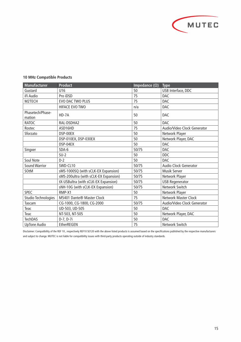
10 MHz Compatible Products
Manufacturer Product Impedance (Ω) TypeGustard U16 50 USB Interface, DDCiFi Audio Pro iDSD 75 DACM2TECH EVO DAC TWO PLUS 75 DAC
HIFACE EVO TWO n/a DACPhasetech/Phase-mation
HD-7A 50 DAC
RATOC RAL-DSDHA2 50 DACRostec ASD16HD 75 Audio/Video Clock GeneratorSforzato DSP-00EX 50 Network Player
DSP-010EX, DSP-030EX 50 Network Player, DACDSP-04EX 50 DAC
Singxer SDA-6 50/75 DACSU-2 50 DDC
Soul Note D-2 50 DACSound Warrior SWD-CL10 50/75 Audio Clock GeneratorSOtM sMS-1000SQ (with sCLK-EX Expansion) 50/75 Musik Server
sMS-200ultra (with sCLK-EX Expansion) 50/75 Network PlayertX-USBultra (with sCLK-EX Expansion) 50/75 USB RegeneratorsNH-10G (with sCLK-EX Expansion) 50/75 Network Switch
SPEC RMP-X1 50 Network PlayerStudio Technologies M5401 Dante® Master Clock 75 Network Master ClockTascam CG-1000, CG-1800, CG-2000 50/75 Audio/Video Clock GeneratorTeac UD-503, UD-505 50 DACTeac NT-503, NT-505 50 Network Player, DACTechDAS D-7, D-7i 50 DACUpTone Audio EtherREGEN 75 Network Switch
Disclaimer: Compatibility of the REF 10 , respectively REF10 SE120 with the above listed products is assumed based on the specifications published by the respective manufacturers
and subject to change MUTEC is not liable for compatibility issues with third-party products operating outside of industry standards
REF 10
16
Appendix
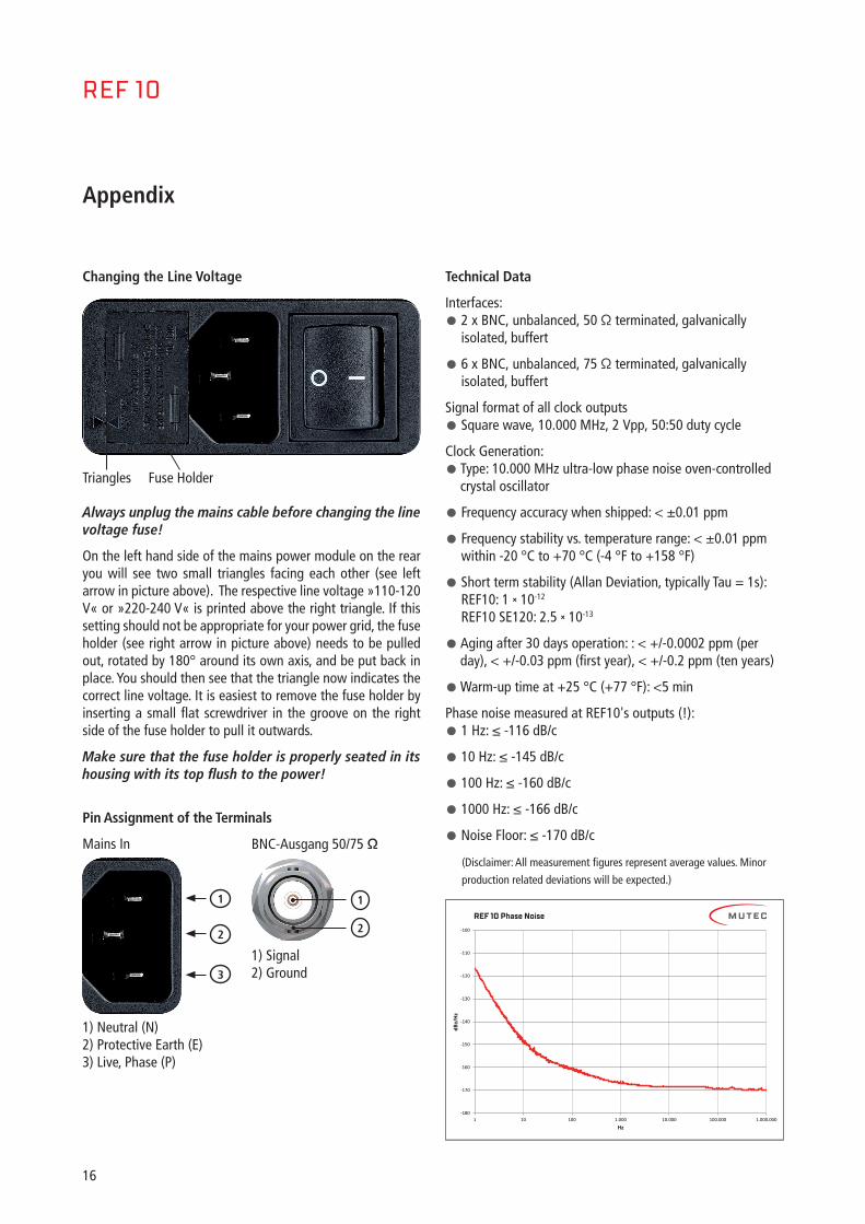
Changing the Line Voltage
Always unplug the mains cable before changing the line voltage fuse!
On the left hand side of the mains power module on the rear you will see two small triangles facing each other (see left arrow in picture above) The respective line voltage »110-120 V« or »220-240 V« is printed above the right triangle If this setting should not be appropriate for your power grid, the fuse holder (see right arrow in picture above) needs to be pulled out, rotated by 180° around its own axis, and be put back in place You should then see that the triangle now indicates the correct line voltage It is easiest to remove the fuse holder by inserting a small flat screwdriver in the groove on the right side of the fuse holder to pull it outwards
Make sure that the fuse holder is properly seated in its housing with its top flush to the power!
Pin Assignment of the Terminals
Mains In
1) Neutral (N)2) Protective Earth (E)3) Live, Phase (P)
Technical Data
Interfaces:
• 2 x BNC, unbalanced, 50 Ω terminated, galvanically isolated, buffert
• 6 x BNC, unbalanced, 75 Ω terminated, galvanically isolated, buffert
Signal format of all clock outputs
• Square wave, 10 000 MHz, 2 Vpp, 50:50 duty cycle
Clock Generation:
• Type: 10 000 MHz ultra-low phase noise oven-controlled crystal oscillator
• Frequency accuracy when shipped: < ±0 01 ppm
• Frequency stability vs temperature range: < ±0 01 ppm within -20 °C to +70 °C (-4 °F to +158 °F)
• Short term stability (Allan Deviation, typically Tau = 1s): REF10: 1 × 10-12 REF10 SE120: 2 5 × 10-13
• Aging after 30 days operation: : < +/-0 0002 ppm (per day), < +/-0 03 ppm (first year), < +/-0 2 ppm (ten years)
• Warm-up time at +25 °C (+77 °F): <5 min
Phase noise measured at REF10's outputs (!):
• 1 Hz: ≤ -116 dB/c
• 10 Hz: ≤ -145 dB/c
• 100 Hz: ≤ -160 dB/c
• 1000 Hz: ≤ -166 dB/c
• Noise Floor: ≤ -170 dB/c
(Disclaimer: All measurement figures represent average values Minor
production related deviations will be expected )
Fuse HolderTriangles
1
2
3
BNC-Ausgang 50/75 Ω
1) Signal 2) Ground
1
2
-180
-170
-160
-150
-140
-130
-120
-110
-100
1 10 100 1.000 10.000 100.000 1.000.000
dBc/
Hz
Hz
Ref 10 Phase NoiseREF 10 Phase Noise
dBc/
Hz
Hz

17
Jitter measured at REF10's outputs (!):
• 1-100 Hz: ≈ 22 fs
Phase noise measured at REF10 SE120's outputs (!):
• 1 Hz: ≤ -120 dB/c
• 10 Hz: ≤ -148 dB/c
• 100 Hz: ≤ -162 dB/c
• 1000 Hz: ≤ -167 dB/c
• Noise Floor: ≤ -170 dB/c
(Disclaimer: All measurement figures represent average values Minor
production related deviations will be expected )
Jitter measured at REF10 SE120's outputs (!):
• 1-100 Hz: ≈ 15 fs
Power Supply:
• Type: internal, linear dual power supply
• Input voltages: 90-125 V / 200-240 V, 50-60 Hz
• Power consumption: 12 W during oscillator warm-up, 8 W nominal operation
• Fuse of power entry module: 2 x FST1,0B,1B, slow-blow, 250 V / 1 A, 20 x 5 mm
Mechanical Details:
• Enclosure size/material/color: 196 x 84 x 300 mm (W x H x D, without connectors and case feet), 1,5mm steel, black powder-coated
• Front panel size/material/surface/color: 198 x 88 x 8 mm (W x H x D), aluminium, anodized incl anodic printing or silk screening, aluminium- or black-colored
• Weight: approx: 4350 g (9 lb, 9 5 oz)
REF10 Order Information:
• Front Aluminum-colored: Item No 8015-105, EAN Code: 4260342461044
• Front black-colored: Item No 8015-106, EAN Code: 4260342461051
REF 10 SE120 Order Information:
• Front Aluminum-colored: Item No 8015-107, EAN Code: 4260342461075
• Front black-colored: Item No 8015-108, EAN Code: 4260342461082
0,0
5,0
10,0
15,0
20,0
25,0
30,0
35,0
40,0
1 10 100
fs
Hz
Jitter [fs]
Fs
Hz
REF 10 Jitter
-180
-170
-160
-150
-140
-130
-120
-110
-100
1 10 100 1.000 10.000 100.000 1.000.000
dBc/
Hz
Hz
Ref 10 Phase NoiseREF 10 SE120 Phase Noise (typical)
dBc/
Hz
Hz
0,0
5,0
10,0
15,0
20,0
25,0
30,0
35,0
40,0
1 10 100
fs
Hz
Jitter [fs]
Fs
Hz
REF10 SE120 Jitter (typical)
