manual-marmiton-cook-cicero-16-000 en 2 - … · july 13, 2017 4 appliance dimension specifications...
TRANSCRIPT

July 13 2017 Printed in Canada
Instruction Manual
PLEASE READ CAREFULLY AND KEEP THIS MANUAL FOR FUTURE REFERENCE
490, rue de l'Argon
Québec, CANADA G2N 2C9
Tél.: 418-849-8095 Fax : 418-849-0077
www.jaroby.com
Certified and tested according to Canadian Safety: ULC S627-00
United States Safety: UL 1482-2011 Emission: EPA Method 28R, ASTM2510
Efficiency: CSA/B415.1.10
Marmiton - Cook - Cicero
Wood stove with cooking capability
July, 13 2017 2
TABLE OF CONTENTS
INTRODUCTION ............................................................................ 3
LISTING AND CODE APPROVALS ................................................ 3
Appliance certification ................................................................ 3
Mobile home approved ............................................................... 3
BTU & Efficiency Specifications.................................................. 3
WARNING ...................................................................................... 3
APPLIANCE DIMENSION ............................................................... 4
SPECIFICATIONS .......................................................................... 4
INSTALLATION .............................................................................. 5
Fire Prevention ........................................................................... 5
Floor protection .......................................................................... 5
Floor protection plate minimum dimensions ................................ 5
Clearances of the stove until the floor plate protection ................ 5
Minimum clearances to combustible material ............................. 6
Assembly before installation ....................................................... 7
Legs installation .......................................................................... 7
Warmer Assembly (Cook, Cuistot, Cicero and Chief only)........... 8
Firebrick installation .................................................................... 9
Side firebrick installation ............................................................. 9
Back firebrick installation ............................................................ 9
Floor firebrick installation ............................................................ 9
Firebrick installation on the pipes ................................................ 9
Firebox configuration ................................................................ 10
GENERAL STOVE INSTALLATION STEPS ................................. 11
Considering a location .............................................................. 11
General installation steps ......................................................... 11
Chimney pipe installation.......................................................... 12
How to set the pipe sections ..................................................... 12
Mobile home installation ........................................................... 13
CHIMNEY INSTALLATION STEPS .............................................. 14
Inside Masonry Chimney, Vertical Installation ........................... 15
Outside Vertical Installation ....................................................... 15
Cathedral Vertical Installation ................................................... 16
Offset Installation ...................................................................... 16
Vertical Installation .................................................................... 17
EXTERNAL COMBUSTION AIR SOURCE ................................... 18
Exterior Air Intake pipe ............................................................. 18
Installation of Air Intake Pipe ..................................................... 18
Air Intake Obstruction ............................................................... 18
STAINLESS STEEL TUBES REPLACEMENT ............................. 19
Stainless steel tubes Installation............................................... 19
How to install the tubes ............................................................. 19
OPERATING INSTRUCTIONS ..................................................... 20
Burning regime control ............................................................. 20
Lightning fire ............................................................................. 20
First fire ................................................................................... 20
Keeping a fire .......................................................................... 21
Fuel Selection .......................................................................... 21
Moisture Meter Information ....................................................... 21
Things not to burn ..................................................................... 21
Wood storage .......................................................................... 21
Draft......................................................................................... 21
Usage of cooking area and oven ............................................. 22
Cooking Area ............................................................................ 22
Use of cooking holes ................................................................. 22
Lids above the firebox ............................................................... 22
Lids above the oven .................................................................. 22
Optional cooking plate .............................................................. 22
Oven usage .............................................................................. 23
Thermometer ............................................................................ 24
Cleaning of the creosote build-up .............................................. 24
Clean up procedure .................................................................. 24
MAINTENANCE ............................................................................ 25
Ash Removal ........................................................................... 25
Ash Disposal ............................................................................ 25
Creosote Formation ................................................................. 25
Chimney Inspection ................................................................. 25
Chimney Sweeping .................................................................. 25
Door maintenance ................................................................... 26
Air tight Adjustment.................................................................. 26
Door adjustment (right side) ...................................................... 26
Cleaning up glass ..................................................................... 26
Disassembly and reassembly of the door .................................. 26
Replacing broken glass ............................................................. 26
Fiberglass rope replacement ..................................................... 27
IN CASE OF CHIMNEY FIRE ....................................................... 27
APPENDIX 1 ................................................................................. 28
Exploded diagram of doors ...................................................... 28
APPENDIX 2 ................................................................................. 32
Installation and operation manual of the optional water tank.... 32
Installation du réservoir ............................................................. 33
Filling of the water tank ............................................................. 34
Water tank’s usage ................................................................... 34
Cleaning of the water tank ........................................................ 34
APPENDIX 3 ................................................................................. 35
Replaceable parts .................................................................... 35
J. A. ROBY LIMITED LIFE WARRANTY ....................................... 36

July 13, 2017 3
INTRODUCTION This manual describes the operation and installation of J.A. Roby cook stove model: Cuistot. This appliance meets the 2020 U.S. Environmental Protection Agency's emission standard with Douglas-fir crib wood. The capacity of this appliance is from 9806 to 21782 BTU/h.
Read all instructions carefully before installing your new J.A. Roby Cuistot cook stove. A good installation is very important for a safe and effective use of this appliance. If you have doubts about how to install your appliance correctly, we suggest to call a professional installer. A wrong installation may result in a fire, burns or even death.
When this stove is not properly installed, it may result in fire. To reduce the risk of fire, follow the installation instructions. Contact local building or fire departments about restrictions and requirement about installation in your area.
Keep these instructions for future reference.
This appliance must be connected to:
• A HT type factory-built chimney approved UL103 or ULC 629 with 6 inches diameter (15.24 cm);
• A code-approved masonry chimney with a flue liner with a 6 inches diameter (15.24cm). The masonry chimney liner must be made of stainless steel and meet the standards for masonry chimney with inner sleeve
LISTING AND CODE APPROVALS
Appliance certification The Cuistot cook stove meets the 2020 U.S. Environmental Protection Agency's emission standard with Douglas-fir crib wood.
This appliance also meets:
• UL 1482-2011 Standard for Solid-Fuel Type Room Stoves;
• ULC S627-00 Standard for Space Heaters for use with Solid Fuels;
• (UM) 84-HUD, Mobile Home approved.
THIS WOOD STOVE HAS A FACTORY MINIMUM AND MAXIMUM BURN RATE SETTING THAT MUST NOT BE ALTERED.
IN THE UNITED STATE IT IS AGAINST FEDERAL REGULATIONS TO ALTER THIS SETTING OR OTHERWISE OPERATE THIS WOOD STOVE IN A MANNER INCONSISTENT WITH INSTRUCTIONS IN THIS MANUAL.
This wood stove needs regular inspection and repair for proper operation (see pages 19-20, 26-28). It is against U.S, federal regulations to operate this wood stove in an inconsistent manner with the operating instructions in this manual.
Mobile home approved This appliance is approved for mobile home installation. The structural integrity of the mobile home floor, ceiling, and walls must be maintained and respect construction code.
When installed in mobile home, the appliance must be properly grounded to the frame of the house and use only a listed double-wall steel pipe.
The appliance must be fixed on the floor by the bottom notch of legs or by the opening at the bottom of base.
DO NOT INSTALL IN A SLEEPING ROOM.
Fresh air intake is mandatory for mobile home use.
BTU & Efficiency Specifications
• Average efficiency 64.47%
• Particle emission 1.9g/h
• Minimum Heat Output* : 9806 BTU/h
• Maximum Heat Output* : 21782 BTU/h
• Cord Wood Load : 70 000 BTU
• Vent size 6"
• Firebox size 1.69 ft3
• Recommended wood length: 20 inches
• Fuel Orientation: front to back
• Fuel: Seasoned cord wood.
* BTU outputs are based on the EPA official test in reference to particle emission using Douglas-fir crib wood with controlled dimension, humidity and volume.
WARNING If this appliance is in an area where children can reach it, it is recommended to place a fire guard in front of the appliance.
THE APPLIANCE GETS HOT WHILE IN OPERATION. KEEP CHILDREN, CLOTHINGS AND FURNITURES AWAY, CONTACT MAY CAUSE BURNS.
N.B: BE WARNED THAT THE LOCAL CODES AND RULES CAN HAVE MORE SPECIFIC REQUIREMENTS THAN THIS MANUAL. YOU CAN CONSULT A PROFESSIONAL INSTALLER, FIRE DEPARTMENTS OR LOCAL AUTHORITY ABOUT INSTALLING SOLID FUEL APPLIANCE IN YOUR AREA.
YOU MIGHT NEED TO OBTAIN A PERMIT FOR INSTALLING THE CHIMNEY AND THE STOVE.
DO NOT CONNECT THIS APPLIANCE TO A CHIMNEY FLUE ALREADY SERVING ANOTHER APPLIANCE.
DO NOT CONNECT TO OR USE IN CONJUNCTION WITH ANY AIR DISTRIBUTION DUCTWORK WHICH ARE NOT APPROVED FOR SUCH INSTALLATIONS.
THIS APPLIANCE IS BUILT FOR BURNING SEASONED CORDWOOD ONLY. USE OF ANY OTHER TYPE OF FUEL SUCH AS COAL, CONSTRUCTION WOOD, TREATED WOOD, FLAMABLE LIQUID, TRASH CAN OVERHEAT AND DAMAGE THE STOVE.
DO NOT OBSTRUCT THE SPACE BENEATH THE STOVE.

July 13, 2017 4
APPLIANCE DIMENSION
SPECIFICATIONS
Elda Marmiton Cuistot Cook Chief Cicero
Combustible Firewood Firewood Firewood
Dry cord wood load 70 000 BTU (73 800 KJ)
70 000 BTU (73 800 KJ)
70 000 BTU (73 800 KJ)
Recommended surface area 1000-1 800ft²(167 m²) 1000-1 800ft²(167 m²) 1000-1 800 ft² (167 m²)
Capacity 21 782 BTU/h
(6.4 Kw/h) 21 782 BTU/h
(6.4 Kw/h) 21 782 BTU/h
(6.4 Kw/h)
Flue pipe diameter 6 in (15.2 cm) 6 in (15.2 cm) 6 in (15.2 cm)
Minimal chimney height 12 ft (366 cm) 12 ft (366 cm) 12 ft (366 cm)
Exterior height 37½ in (95.25 cm) 58½ in (148.6 cm) 58½ in (148.6 cm)
Exterior width 41⅝ in (105.7 cm) 41⅝ in (105.7 cm) 51¾ in (131.4 cm)
Exterior depth 26¼ in (66.7 cm) 26¼ in (66.7 cm) 26¼ in (66.7 cm)
Door opening 9 x 9⅛ in
(22.9 x 23.2 cm) 9 x 9⅛ in
(22.9 x 23.2 cm) 9 x 9⅛ in
(22.9 x 23.2 cm)
Interior height 11⅝ in (29.5 cm) 11⅝ in (29.5 cm) 11⅝ in (29.5 cm)
Interior width 12 in (30.5 cm) 12 in (30.5 cm) 12 in (30.5 cm)
Interior depth 20 in (50.8 cm) 20 in (50.8 cm) 20 in (50.8 cm)
Maximum log length 20 in (50.8 cm) 20 in (50.8 cm) 20 in (50.8 cm)
Average combustion time 3-6h 3-6h 3-6h
Weight 468 lb
(212 kg) 448 lb
(203 kg) 532 lb
(241 kg) 510 lb
(231 kg) 567 lb
(257 kg) 546 lb
(247 kg)
Efficiency 64.47% 64.47% 64.47%

July 13, 2017 5
INSTALLATION
Fire Prevention To prevent risk of fire, serious consideration should be given to the following:
1. Install at least one smoke detector on each floor in your home. They should be located within a reasonable distance from the heating appliance and close to bedrooms. Follow the smoke detector manufacturer instructions regarding placement and installation and check regularly if they work properly.
2. Keep a Class-A fire extinguisher within reach in case of small fires on the floor resulting from burning embers.
3. Install a CO detector in the room with the appliance.
4. Make an evacuation plan with at least two exits. All the occupants must know this plan.
5. A procedure in case of chimney fire:
a. Close all the air intakes of the appliance if possible.
b. Evacuate the house immediately
c. Notify local fire department.
Floor protection Your stove must be installed on a non-combustible material plate to protect the floor and avoid fire that might be caused by:
• Projections of sparks when opening door or loading logs;
• The heat radiation from the stove which might cause an auto-ignition to the floor or to the floor covering;
• Possible flow of creosote when there is a fire chimney.
The coating used for the protection must be non-combustible and approved according to UL1618 standard for the USA or to the local codes (Example: cement, brick, ceramic tiles, etc.)
HORIZONTAL VENTING MANDATORY PROTECTION: Non-combustible floor protections must extend beneath the flue pipe when installed with horizontal venting and it should extend 2 inches (51 mm) beyond each side of the pipe projection on the floor.
You can extend the protection plate while respecting the clearances of each side of the stove.
Floor protection plate minimum dimensions The following dimensions are the minimum values and they can be greater.
• Width: 57 ⅝ inches (146.4 cm)
• Depth: 51 inches (129.5 cm)
• Thickness: 3/8 inches (1 cm)
In the United States, the depth can be less than the value above.
• Depth: 49 inches (124.5)
Clearances of the stove until the floor plate protection The following dimensions are the minimum values and they can be greater.
Canada:
• 8 in (20.3 cm) rear
• 8 in (20.3 cm) side
• 18 in (45.7 cm) from the door glass
United States:
• 8 in (20.3 cm) rear
• 8 in (20.3 cm) side
• 16 in (40.64 cm) from the door glass

July 13, 2017 6
Minimum clearances to combustible material
With these reduced clearances, this appliance takes a minimum installation space. Whether in the living room or in the dining room, this appliance will complete your decor by his originality and warmth.
Here is the minimum clearance for different certified flue pipes:
Double wall flue pipe distance:
Single wall flue pipe with shield:
Single wall flue pipe:
To know how to reduce those dimensions, you have to contact your local authority for installing an heat shield on a wall. Installations with reduced clearances must comply with NFPA211 or CAN/CSA-B365 standards.
Minimum Ceiling Height

July 13, 2017 7
Assembly before installation The stove leg and the warmer top might not be assembled in the factory, in order to save space for transportation and storage. You must therefore assemble these parts before installing the cook stove.
NEVER USE THE STOVE WITHOUT THE LEGS INSTALLED.
Legs installation
1) Take out legs and bricks from the firebox.
2) Unscrew the stove from the skid, and remove the warmer.
3) Ask for help to remove the cook stove from the pallet and to place it on the floor.
4) With the help of another person, put the appliance on its back on the pallet as shown in the image below. If you have another pallet, you can stack it on top of one another, it will make it easier when it will be the time to put the stove back on its legs.
5) Unscrew slightly the nut that holds the washer without removing it. (1 & 2)
6) Slide the supporting part of the leg under the washer (#3) as illustrated (Attention: Be sure to put the edges of the leg support against the screws acting as a stopper (#4). Fasten the leg and the washer (2) to the appliance by screwing the nut tightly (1).

July 13, 2017 8
Warmer Assembly (Cook, Cuistot, Cicero and Chief only) At this point, you need to know which type of smoke pipe you’ll use: single wall pipe or double wall pipe.
For the single smoke pipe, it’s not necessary to remove the pre-cut metal part.
For the double smoke pipe, you must remove the pre-cut metal part on the top and inside the warmer (1), as well as the decorative faceplate (2).
1) Open the installation opening at the bottom right of the warmer by removing the screws (5) and the plate (4)
2) Place and align the warmer with the corresponding holes on the top of the stove. You will have two bolts on each extremity (3) and they can be accessed under the top by the lids. Two other screws are located on each side of the flue collar (4), and can be access by the collar or by the round cooking hole for a total of 6 screws (3&4).
3) Fix the warmer with the lock washers (2) and the nuts(1).

July 13, 2017 9
Firebrick installation
Side firebrick installation Put 4 bricks « A » and 2 bricks « B » as shown.
Back firebrick installation Put 2 bricks « A » and 1 brick « C » in the back and place the 2 bricks «H» on top. Screw in the triangular firebrick retainer ( I )
Floor firebrick installation Put 2 bricks « A », 2 bricks « H », 1 brick « I », 1 brick « G » as shown in the image below.
Firebrick installation on the pipes The firebricks must be put on the 5 pipes on the front of combustion chamber. Bricks keep the maximum heat inside the combustion chamber and help the air from the tube burn the most of the gas from wood which wouldn’t be burnt in any other manner.
The rockwool above the brick prevents leakage between the bricks and keeps a maximum heat inside combustion chamber. It must cover up all the bricks and the air corridors of both sides.
IMPORTANT: The rockwool must not obstruct the smoke path. Check the rockwool by removing the left top lid hole in the hob and make sure that it is in a good position. Place the two half-round steel plate on the rockwool as illustrated.
1. From the hole in the hob, put 2 bricks « A » and 1 brick « C », over the whole length of 3 the pipes in the back. Push the bricks against the back bricks with a slight angle as shown in the image.
2. Place 2 bricks « K » and 1 brick « J » over the whole length of the 3 pipes at the front in the same manner as step1.

July 13, 2017 10
Firebrick installation on the pipes (suite)
3. Insert the rockwool over the bricks and check from the hole in the hub that the smoke path is not obstructed. There must be 1 inch (2.54 cm) or more between the rockwool and the deflector.
4. Put the two half-round steel plates over the rockwool near the rear deflector already in place. Be sure to put them under the rear deflector to maximise the clearance between the rockwool and the rear deflector. Make sure the rockwool is not obstructing the space by looking under the cooking lid on the hub.
WARNING: Obstructing the smoke path under the deflector can force smoke to exit by the door when it’s open and it will cause the stove not to work properly.
Firebox configuration
July 13, 2017 11
GENERAL STOVE INSTALLATION STEPS
Considering a location We recommend to install this appliance by a certified installer.
Consideration must be given to:
� Safety;
� Passage frequency;
� Convenience;
� type of chimney and required chimney pipe;
� Draft.
Drawing your installation plan on paper is a good way to avoid mistakes.
Write on the plan:
• Exact dimensions for clearances to combustible material;
• Exact dimensions of the floor protection;
• Measurements of the chimney location. (If not already installed. Be sure to have all the clearances recommended by the factory-built chimney manufacturer for the floor, ceiling and roof).
We recommend that a qualified building inspector and your insurance company representative review your plan before and after installation.
General installation steps 1) Read the entire installation manual before installing and
using your stove.
2) Choose a spot where to install your stove. Read the section about the dimensions of the floor protection plate, the localisation of the stove over the floor protection plate and the combustible material clearances (page 5). Once you have decided where to install the stove, mark the floor at the center of the chimney.
� To make sure that the vertical center of the chimney, use a plumb line and mark the center on the floor.
3) Check if it is possible to pass the chimney without damaging the structure of your house. You might have to move the location of the stove while keeping the minimum clearances. If you have to cut a joist, be sure to respect the building code in effect to keep the structural integrity of your house.
� We recommend installation of this appliance by a certified installer.
Note This appliance have to be connected to 6 inches
(15.24 cm) factory build chimney HT UL 103 or CAN/ULC S629 compliant or a 6 inches (15.24 cm) masonry chimney with a homologated sleeve inside. The masonry chimney liner must be made of stainless steel and meet the standards for masonry chimney with inner sleeve.
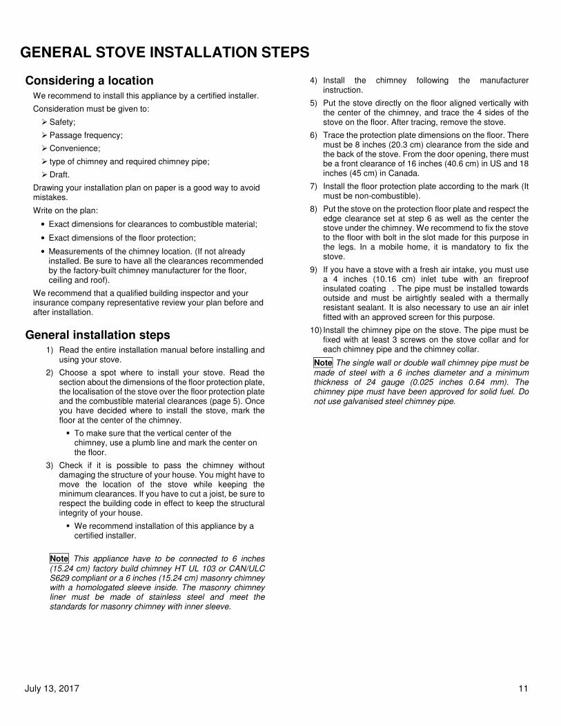
4) Install the chimney following the manufacturer
instruction.
5) Put the stove directly on the floor aligned vertically with the center of the chimney, and trace the 4 sides of the stove on the floor. After tracing, remove the stove.
6) Trace the protection plate dimensions on the floor. There must be 8 inches (20.3 cm) clearance from the side and the back of the stove. From the door opening, there must be a front clearance of 16 inches (40.6 cm) in US and 18 inches (45 cm) in Canada.
7) Install the floor protection plate according to the mark (It must be non-combustible).
8) Put the stove on the protection floor plate and respect the edge clearance set at step 6 as well as the center the stove under the chimney. We recommend to fix the stove to the floor with bolt in the slot made for this purpose in the legs. In a mobile home, it is mandatory to fix the stove.
9) If you have a stove with a fresh air intake, you must use a 4 inches (10.16 cm) inlet tube with an fireproof insulated coating . The pipe must be installed towards outside and must be airtightly sealed with a thermally resistant sealant. It is also necessary to use an air inlet fitted with an approved screen for this purpose.
10) Install the chimney pipe on the stove. The pipe must be fixed with at least 3 screws on the stove collar and for each chimney pipe and the chimney collar.
Note The single wall or double wall chimney pipe must be
made of steel with a 6 inches diameter and a minimum thickness of 24 gauge (0.025 inches 0.64 mm). The chimney pipe must have been approved for solid fuel. Do not use galvanised steel chimney pipe.
July 13, 2017 12
Chimney pipe installation
The chimney pipe is a set of single wall or double wall flue pipes and installed in-between the stove collar and the chimney thimble. The single wall chimney parts are sold at most hardware store but these are not approved nor certified. It is therefore recommended to follow the minimum clearances to combustible (see page 6). Moreover, there is a series of rules which can be found in the installation codes for solid fuel appliance.
� Double wall chimney pipe
The stove was designed and tested with a single wall chimney pipe with an heat shield. However, it is possible to install a 6 inches (15.2 cm) double wall certified chimney pipe.
ATTENTION
• For the minimum clearance between combustible materials and double wall chimney pipe, see the manufacturer manual.
� Single wall chimney pipe
Single wall chimney pipe sections must have a 6 inches diameter which corresponds to the diameter of the flue collar and they must be made of steel with a minimum thickness of 22 gauge 0.029 inches (0.85 mm). to reduce the clearance of 50% (18’’ to 9’’) it is recommended to Install a metal heat shield covering straight and elbow sections with a space of 1 inch (25.4 mm) between the shield and the pipe.
ATTENTION
• If an heat shield is not installed, you must move away the stove to keep an 18 inches (45.7 cm) clearance between combustibles materials and the chimney pipe. The horizontal section must have an upward slope of at least 1/4 inch (6.35 mm) by feet (30 cm) and must not exceed 36’’ of total horizontal length (91.4 cm).
• Clearance to combustible (for example plaster board roof) must be 18 inches (45.7 cm) or more for single wall chimney pipe.
• Clearance to combustible must follow the pipe manufacturer indication’s for approved double wall chimney pipe,.
ALL PIPE SECTIONS MUST BE CLEAN AND IN GOOD CONDITION, AND THEY MUST BE APPROVED FOR CORDWOOD FUEL.
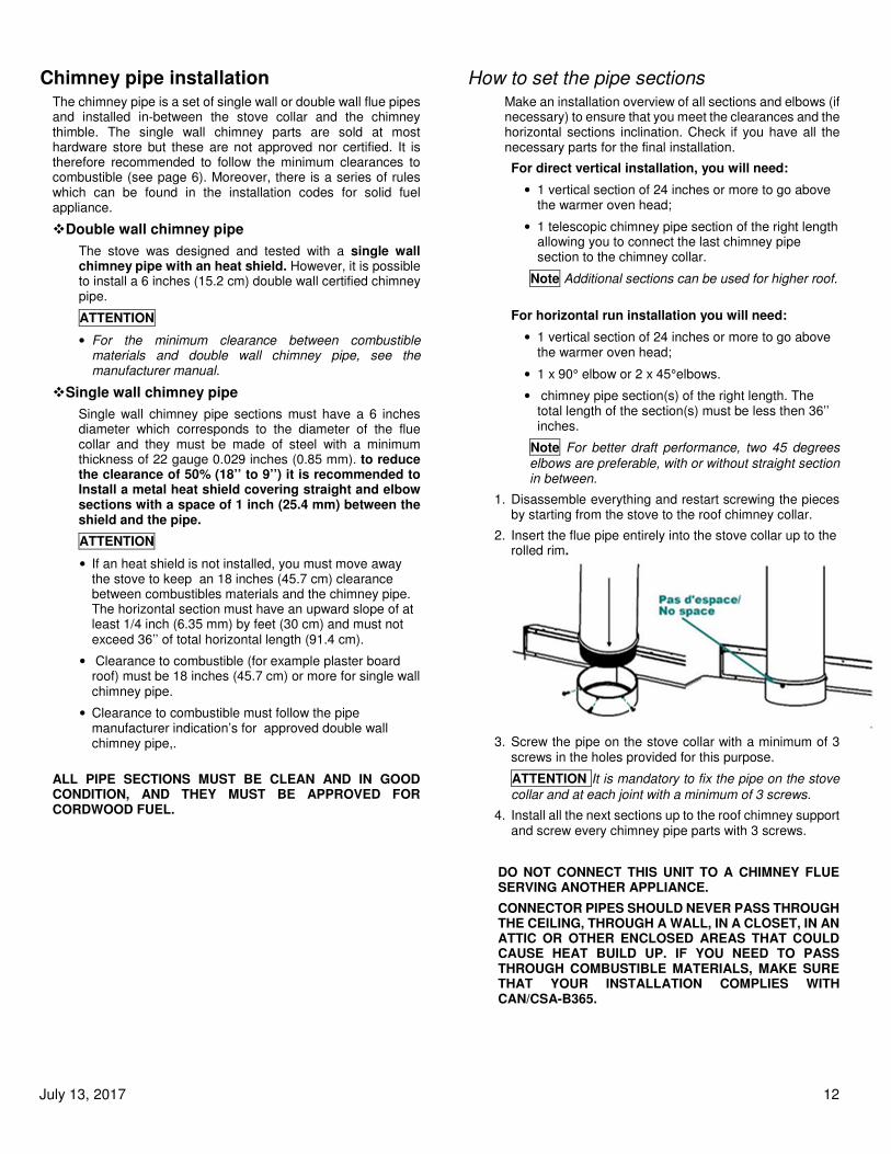
How to set the pipe sections Make an installation overview of all sections and elbows (if necessary) to ensure that you meet the clearances and the horizontal sections inclination. Check if you have all the necessary parts for the final installation.
For direct vertical installation, you will need:
• 1 vertical section of 24 inches or more to go above the warmer oven head;
• 1 telescopic chimney pipe section of the right length allowing you to connect the last chimney pipe section to the chimney collar.
Note Additional sections can be used for higher roof.
For horizontal run installation you will need:
• 1 vertical section of 24 inches or more to go above the warmer oven head;
• 1 x 90° elbow or 2 x 45°elbows.
• chimney pipe section(s) of the right length. The total length of the section(s) must be less then 36’’ inches.
Note For better draft performance, two 45 degrees
elbows are preferable, with or without straight section in between.
1. Disassemble everything and restart screwing the pieces by starting from the stove to the roof chimney collar.
2. Insert the flue pipe entirely into the stove collar up to the rolled rim.
3. Screw the pipe on the stove collar with a minimum of 3 screws in the holes provided for this purpose.
ATTENTION It is mandatory to fix the pipe on the stove
collar and at each joint with a minimum of 3 screws.
4. Install all the next sections up to the roof chimney support and screw every chimney pipe parts with 3 screws.
DO NOT CONNECT THIS UNIT TO A CHIMNEY FLUE SERVING ANOTHER APPLIANCE.
CONNECTOR PIPES SHOULD NEVER PASS THROUGH THE CEILING, THROUGH A WALL, IN A CLOSET, IN AN ATTIC OR OTHER ENCLOSED AREAS THAT COULD CAUSE HEAT BUILD UP. IF YOU NEED TO PASS THROUGH COMBUSTIBLE MATERIALS, MAKE SURE THAT YOUR INSTALLATION COMPLIES WITH CAN/CSA-B365.

July 13, 2017 13
Mobile home installation DANGER DO NOT INSTALL IN BEDROOM.
WARNING THE STRUCTURAL INTEGRITY OF THE MOBILE HOME FLOOR, WALL, AND CEILING/ROOF MUST BE MAINTAINED.
VAPOR BARRIER EFFICACITY AROUND THE CHIMNEY AND FRESH AIR INTAKE MUST BE KEPT IN GOOD CONDITION.
1) Follow the «General stove installation» (p.10) from steps 1 to 10.
2) The following requirements are MANDATORY for mobile home installation.
a. The stove must be fixed permanently on the mobile home’s floor with bolts and nuts.
b. The exterior air intake must be installed.
c. The stove must be electrically-grounded to the mobile home’s chassis. In the USA, electrical grounding with 8 gauge wire using star washers and certified terminals is mandatory.
d. All of the following equipment must be certified and approved for mobile home installation.
• Double wall chimney pipe;
• The chimney system;
• The roof flashing;
• The Storm collar;
• Chimney cap with fire screen;
• Firewall;
• Chimney ceiling support;
• Decorative collar.
e. If the chimney is exposed outside from a wall and placed lower than 7 feet (213 cm) above the ground level where the mobile home is situated, a guard must be installed around the chimney at the height of 7 feet (213 cm). If openings are made in the guard, they must be less than ¾ inch (19.5 mm) wide. guard openings must be kept at least 4 inches (10.2 cm) away from the chimney surface in order to avoid contact.
f. The chimney must exceed of at least 3 feet (91.4 cm) the highest point of the opening made in the roof and it must also exceed of 2 feet the highest point of the roof inside a 10 feet distance from the chimney.
g. Be sure to seal correctly the flashing of the roof, the firewall and the exterior air intake with sealant. You should also pay attention to the efficacy of the vapor barrier is not compromised.
3) Always keep the door closed. Open it only when adding wood or when starting a fire.
4) To close the exterior air intake when the stove is not in use, a damper must be installed in the air intake pipe.
5) Don’t forget to open the damper when you operate your stove so that smoke will not fill the house.
6) Always use certified parts for mobile home. Never use a substitute for replacement.

July 13, 2017 14
CHIMNEY INSTALLATION STEPS Use only approved chimneys, the same size as the stove collar, 6 inches in this case. The chimneys used must be tested according to CAN/ULC S629 M87 in Canada and to UL 103 (Type HT chimneys in Standard for Chimneys, Factory-Built, Residential Type and Building Heating Appliance) in USA. The stove can be installed with a masonry chimney according to ULC S635, ULC S640 and UL 1777. The masonry chimney must be equipped with a stainless steel sleeve and meet the standards for masonry chimney with inner sleeve.
Provide a place for sweeping.
It is preferable, if possible, to avoid a chimney built outside of the house or of an exterior wall, especially in cold regions. Outside chimneys generally have a less efficient draft. In some conditions, they can even have an reverse draft because and it can be hard to heat them enough so that they can reach their operating temperature. A greater accumulation of creosote, a less efficient draft and a lesser performance are some characteristics of cold chimneys. Draft is proportional to the total chimney height as well as its temperature. It is therefore possible to get a better draft by increasing the chimney's height and by reducing the heat loss with an insulated lining. Make sure that all smoke pipe joints are really airtight. A leak reduces the efficiency of the appliance and could even make its use dangerous.
NOTE This is a general chimney installation method. Always refer to the chimney manufacturer’s manual for a more detailed method for your chimney.
1) Determine the total length necessary for your chimney.
2) Cut the holes in all the floors and in the roof.
3) If you need to cut a joist, be sure to strengthen the adjacent joists and frame the hole respecting the minimum dimensions between combustible materials and the firewall. Follow the manufacturer's instructions in the manual provided with the firewall. Never cut a structural beam.
4) Frame the holes on each floor and attic respecting the minimum distance recommended by the manufacturer's manual of your chimney. Install firewalls on each floor.
5) Frame the hole in the roof.
6) Install the chimney support and firewall in the ceiling where the stove is installed.
7) Stack and lock the factory built chimney section on the support and above the roof.
• The chimney must exceed of at least 3 feet (91.4 cm) the highest point of the roof opening.
• The chimney must also be 2 feet over the highest point on the roof within a 10 fts (304 cm) radius around chimney.
• The minimum length of chimney is 12 feet (365.8 cm).
ATTENTION Be sure the chimney section are attached together properly and locked onto the chimney support.
NOTE A good length of chimney can help to obtain
effective performances of your stove. Try the minimum length first then add section if you need more draft.
8) Put the roof flashing over the chimney and seal it with roof caulking.
9) Nail the roof flashing, and reinstall the roof covering.
10) Slide the storm collar over the chimney and seal it with high temperature caulking.
11) Lock the chimney cap and install the fire screen if necessary
Note
• Chimney performance may vary.
• Chimney temperature, the appliance’s location in the house, the house aerodynamic, buildings, trees, roof lines and wind conditions can cause backdraft in the chimney,
• Chimney height might need adjustment if backdraft or overdraft occurs.

July 13, 2017 15
Inside Masonry Chimney, Vertical Installation The wood stove must be installed in accordance with the applicable local laws or the CAN/CSA-B365, NFPA211 (USA) norms regarding the installation of chimney. Follow the chimney manufacturer’s instructions.
The masonry chimney must have a certified stainless steel sleeve inside covering up all the chimney height. The sleeve must be at the same diameter as the flue collar. The connection must be tight and sealed to avoid fume to go indoor.
To pass into a wall between the stove and the masonry chimney, installation methods have been set to prevent fire. Contact your local authority to find the latest information in terms of construction standards.
To install a stove with a chimney serving a masonry fireplace, you must have a certified stainless steel sleeve inside covering up all the chimney height. The sleeve must have the same diameter as the flue collar. The connection must be tight and sealed to avoid fume to go indoor. Don’t forget to add an opening for sweeping.
Outside Vertical Installation The wood stove must be installed in accordance with the applicable local laws or the CAN/CSA-B365, NFPA211 (USA) norms. Regarding the installation of chimney, follow the chimney manufacturer’s instructions.
To pass into a wall between the stove and the masonry chimney, the installation method has been set to prevent fire. Contact your local authority to find the latest information in terms of construction standards.

July 13, 2017 16
Cathedral Vertical Installation The wood stove must be installed in accordance with the applicable local laws or the CAN/CSA-B365, NFPA211 (USA) norms. Regarding the installation of chimney, follow the chimney manufacturer’s instructions.
Always pass chimney between joists. If a joist need to be cut, refer to the Local Building code to know how to do it safely. Otherwise, ask a carpenter or a certified Installer.
Always frame around chimney. Keep the minimal clearances as written in your chimney manual.
Do not fill the space between the frame and the chimney. Nothing must be in contact with the chimney.
Always install a firewall at each level, floor, ceiling, attic and roof.
Always pass into a level joist with a straight section.
The chimney should be supported by the cathedral roof. Build a support frame around the chimney to support its weight. The weight of the chimney must never be supported by the stove.
Offset Installation The wood stove must be installed in accordance with the applicable local laws or the CAN/CSA-B365, NFPA211 (USA) norms. Regarding the installation of chimney, follow the chimney manufacturer’s instructions.
Always pass chimney between joists. If a joist need to be cut, refer to the local building code to know how to do it safely. Otherwise, ask a carpenter or a certified Installer.
Always frame around chimney. Keep minimal clearances as written in your chimney manual.
Do not fill the space between the frame and the chimney. Nothing must be in contact with the chimney.
Always install a firewall at each level, floor, ceiling, attic and roof.
A special firewall need to be install in the attic. It allows to keep the insulation layers away from the chimney.
Always pass into a level joist with a straight section.
Chimney weight has to be supported by the lower floor and the ceiling support.
The weight of the chimney must never be onto the elbows. Install a support strip to hold the upper straight section over the elbow.
The weight of the chimney must never be supported by the stove.
Some restrictions are indicated regarding the maximum angle and length of the angular section. See the chimney manual or local building code.

July 13, 2017 17
Vertical Installation
The wood stove must be installed in accordance with the applicable local laws or the CAN/CSA-B365, NFPA211 (USA) norms. Regarding the installation of chimney, follow the chimney manufacturer’s instructions.
Always pass chimney between joists. If a joist need to be cut, refer to the Local Building code to know how to do it safely. Otherwise, ask a carpenter or a certified Installer.
Always frame around chimney. Keep minimal clearances as written in your chimney manual.
Do not fill the space between the frame and the chimney. Nothing must be in contact with the chimney.
Always install a firewall at each level, floor, ceiling, attic and roof.
A special firewall need to be install in the attic. It allows to keep the insulation layers away from the chimney.
Always pass into a level joist with a straight section.
Chimney weight has to be supported by the lower floor with a ceiling support.
The weight of the chimney must never be supported by the stove.
Attic firewall

July 13, 2017 18
EXTERNAL COMBUSTION AIR SOURCE
In a conventional house, the natural fresh air supply is sufficient to operate the wood stove properly.
However, in new energy saving houses, some of them could be too air-tight and the fresh air supply might not be sufficient for the stove to operate properly. It is therefore recommended to install an outside combustion air duct to avoid smouldering fire that can cause smoke spill out. This negative pressure in the house can be also caused by some ventilators in motion such as a tumble dryer, cooking fan, bathroom fan, etc.
If there is no outside combustion air duct, it is recommended to open a window slightly in the room where the appliance is placed in order to avoid the negative pressure caused by the appliances mentioned above.
A mobile home on a foundation is considered as a conventional house.
Exterior Air Intake pipe This appliance has an outdoor air intake.
We recommend using a 4 inches (10.7 cm) diameter aluminum fireproof flexible pipe with a fireproof insulating coating, an outside cap and a weatherproof grate.
The grate openings must be smaller than ¼ x ¼ inches (6mm x 6mm).
In case of using air ducts made of other materials, they must complied with ULC-S110 norms or UL-181 Class1 norms. They must also be equipped with fireproof insulation and be corrosion resistant.
THE STOVE MUST BE FIXED TO THE STRUCTURE WHEN AN EXTERIOR AIR INTAKE IS INSTALLED.
Installation of Air Intake Pipe You can find external air intake head and grating in hardware store. (The back panel is removed in the following picture only to show the flue collar)
1) Find the air intake under the appliance
2) Fix the flexible or rigid pipe to the air intake collar with a pipe clamp (A).
To install the outdoor air intake through a wall or a floor, follow the air intake manufacturer installation instructions. Be sure to seal the edge of the hole correctly too prevent loss of your vapour barrier efficacy.
To avoid cold air entering in the stove constantly, we recommend installing a damper which closes the pipe near the outdoor air intake. Install a small rigid section of tube inside the outdoor air intake and put a damper inside the rigid section to close the air Intake. This damper is to reduce the cold air circulation in the stove when it is not in use.
Connect the flexible air intake pipe onto the damper section.
Put a fireproof thermal insulation around the pipe if the pipe is not insulated.
Air Intake Obstruction If the stove extinguishes after closing the door, it’s possible that the outdoor air inlet is obstructed by something, or that the damper of the air intake is closed.
After a long period of disuse, insects or animals can build a nest inside the air intake.
After a storm in winter, snow can accumulate over the air intake and obstruct it.
Before the heating season, always inspect the air intake pipe to be sure nothing is obstructing it.
July 13, 2017 19
STAINLESS STEEL TUBES REPLACEMENT
Although the tubes are in stainless steel, because of the extreme temperatures and conditions inside the firebox, the tubes could eventually corrode and perforate depending of operating conditions. In that scenario, your stove becomes less effective in terms of combustion quality and the tubes will need to be replaced to ensure the performance of your appliance.
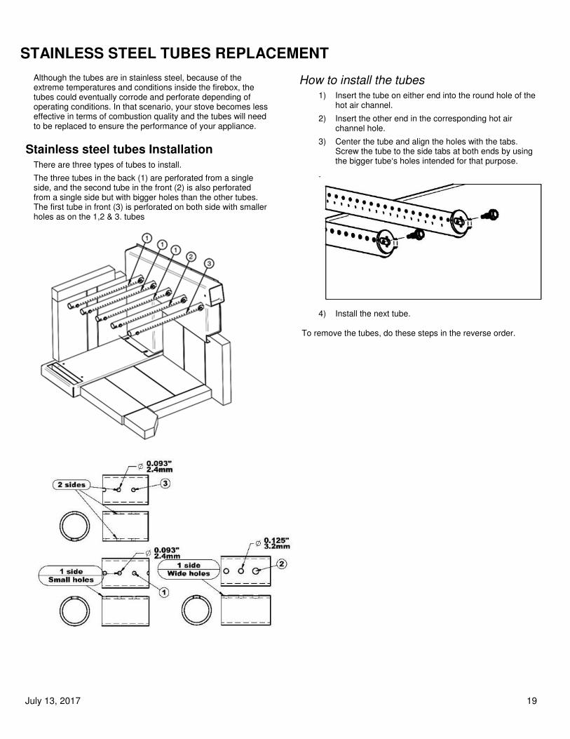
Stainless steel tubes Installation There are three types of tubes to install.
The three tubes in the back (1) are perforated from a single side, and the second tube in the front (2) is also perforated from a single side but with bigger holes than the other tubes. The first tube in front (3) is perforated on both side with smaller holes as on the 1,2 & 3. tubes
How to install the tubes 1) Insert the tube on either end into the round hole of the
hot air channel.
2) Insert the other end in the corresponding hot air channel hole.
3) Center the tube and align the holes with the tabs. Screw the tube to the side tabs at both ends by using the bigger tube‘s holes intended for that purpose.
.
4) Install the next tube. To remove the tubes, do these steps in the reverse order.

July 13, 2017 20
OPERATING INSTRUCTIONS � OPERATE ONLY WHEN DOOR IS CLOSED: KEEPING
THE DOOR OPEN MIGHT RESULT IN A RUNAWAY AND CAUSE PERMANENT DAMAGE TO THE STOVE OR A CHIMNEY FIRE.
� A WOOD BURNING PRODUCES CARBON DIOXIDE (CO2) AND CARBON MONOXIDE (CO) WHICH ARE TOXIC AND LETHAL. IT’S RECOMMENDED TO INSTALL A CO, CO2 DETECTOR IN THE SAME ROOM WHERE THE STOVE IS LOCATED.
� INSTALL ALSO A SMOKE DETECTOR IN THE SAME ROOM WHERE THE STOVE IS LOCATED. THE SMOKE DETECTOR MIGHT GO ON WHEN THERE IS SMOKE LEAKING OUT.
� THIS APPLIANCE IS NOT DESIGNED FOR OTHER FUEL THAN SEASONED CORDWOOD. FUELS SUCH AS COAL, CARDBOARD, ETC. COULD PRODUCE MORE POLUTANT EMISSIONS OR OVERHEAT THE APPLIANCE AND DAMAGE IT.
� NEVER SLAM THE DOOR.
� NEVER BURN INFLAMMABLE LIQUID: INFLAMMABLE LIQUID PRODUCES VERY INTENSE HEAT AND ITS COMBUSTION IS HARD TO CONTROL. IT MIGHT CAUSE RUNAWAY AND OVERHEATING OF THE STOVE. THIS CAN CONSEQUENTLY CAUSE DAMAGE TO THE STOVE, A CHIMNEY FIRE OR A HOUSE FIRE.
� ALWAYS VERIFY IF THE AIR INTAKE IS NOT OBTRUCTED BEFORE LIGHTING A FIRE.
� NEVER ELEVATE FIRE WITH A GRATE OR ANDIRON. ALWAYS MAKE FIRE DIRECTLY AT THE BOTTOM OF THE STOVE.
Burning regime control When the handle under the front stove apron is pushed completely backward, the air admission is reduced. In that configuration, air will only comes out from the secondary air tubes. On the other hand, when the handle is pulled forward, the air admission increases. This air is coming from the openings above the door. This is what we called “primary air admission”.
Warning Operating your stove with the door partially or
fully open for a long period of time can damage the stove.
IT IS PROHIBITED TO MODIFY AIR ADMISSION TO OBTAIN A BRISKER FIRE OR FOR ANY OTHER REASON. MODIFICATIONS CAN VOID WARRANTY.
Lightning fire After installing the stove correctly by following the instructions of the manufacturer, you are ready to light it up.
1) Pull the handle under the front table of the stove forward to let the air admission enter in the combustion chamber.
2) Put paper and kindling wood in the combustion chamber and light the fire in your preferred way.
3) Close the door partially keeping a slight opening. When the chimney is hot enough, close completely the door and leave the air admission handle in the pulled position so that your fire kindle steadily.
4) Once you have a glowing ember bed, it’s time to add logs. Follow now the instruction section on how to keep a fire.
DO NOT FILL THE STOVE OVER THE UPPER BRICK.
You can control the combustion process by opening or closing the air intake. The wood will burn more rapidly with more primary air admission. Otherwise, the wood will burn slower and more efficiently with the air intake handle set to secondary air (minimum).
� NEVER LEAVE THE STOVE UNATTENDED WHEN THE DOOR IS SLIGHTLY OPEN FOR LIGHTING. ALWAYS CLOSE THE DOOR AFTER LIGHTING.
� ALWAYS LEAVE THE DOOR CLOSED WHEN OPERATING THE STOVE.
� NEVER USE CHEMICAL PRODUCTS OR INFLAMMABLE LIQUID TO START THE FIRE OR REVIVE THE FLAME.
� NEVER USE GASOLINE, GASOLINE-TYPE LANTERN FUEL, KEROSENE, CHARCOAL LIGHTER FLUID, OR SIMILAR LIQUIDS TO START OR ’REVIVE’ A FIRE IN THIS STOVE. KEEP SUCH LIQUIDS AWAY FROM THE STOVE WHILE IT IS IN USE.
� DO NOT BUILD FIRE NEAR THE DOOR GLASS.
� KEEP ANY INFLAMMABLE PRODUCTS AWAY FROM THE APPLIANCE.
First fire During the first hours of operation, you must heat the stove gradually in order to allow an appropriate baking of the paint and to facilitate its adhesion to the metal. Do not heat the appliance with a brisk fire so as to avoid a thermal shock which could lift up the paint or fade the color.
Make sure that the room is well ventilated in order to eliminate odours and smoke coming from the paint during the first hours of use. This nuisance is merely temporary.
This special paint is conceived to tolerate temperatures up to1200°F (650°C).

July 13, 2017 21
Keeping a fire To add wood in the stove and keep a fire:
1) Pull the handle under the apron of the stove forward and wait a few seconds to let the fire adjust to the new conditions.
2) Open the door handle to the previous position and wait some time so that the fire has time to adjust
3) Turn the door handle completely and leave the door half-open and let the fire set up.
4) Open the door completely.
5) Move embers near the door with poker to supply it with oxygen and make it burn completely.
6) Add firewood over the ember, keeping it away from the glass door to avoid flame touching the ceramic glass.
ATTENTION
� DO NOT FILL THE STOVE OVER THE UPPER BRICK.
� DO NOT BUILD A FIRE NEAR THE WINDOW.
� THIS APPLIANCE IS DESIGNED TO BURN DRY CORDWOOD. WE DON’T RECOMMEND ANY OTHER TYPE OF WOOD.
7) Close the door slightly and let the wood burn.
8) Once the fire gets stable, close and lock the door.
9) Push the air admission knob to the desired condition.
RISK OF OVERHEATING: NEVER LEAVE THE STOVE UNATTENDED WHEN THE DOOR IS SIGHTLY OPEN. ALWAYS CLOSE THE DOOR AFTER ADDING A LOAD.
DO NOT USE ANY INFLAMMABLE LIQUID TO REKINDLE THE FIRE.
Fuel Selection
This stove is designed to burn only firewood. Using firewood dried properly will result in an higher efficiency and a lower pollutant’s emission compared with using softwood or fresh wood.
Moisture Meter Information Firewood is ready to use at 10‐25% moisture content.
Fresh cut logs can have a moisture content of 80% or more, depending on species. During the drying process, wood might shrink, split, twist or change shape. In general, wood must be dried before use. Air drying, i.e. ‘seasoning’ is the most common method used for cordwood.
Season wood outdoor in summer for at least 6 months before use. Properly seasoned wood is darker, has cracks at the ends, and sounds hollow when one piece is smacked against one another.
In most parts in the North America, the minimum moisture content that can be generally obtained by air drying is about 12 to 15 percent.
Things not to burn 1) Garbage;
2) Lawn clippings or yard waste;
3) Materials containing rubber;
4) Plastic materials;
5) Waste containing petroleum products, paints or solvent;
6) Materials containing asbestos;
7) Construction or demolition debris;
8) Railroad ties or pressure-treated wood;
9) Manure or animal remains;
10) Salt water driftwood or other previously salt water saturated materials;
11) Unseasoned wood;
12) Paper products, cardboard, plywood, or particleboard.
The prohibition against burning these materials does not prohibit the use of fire starters made from paper, cardboard, saw dust, wax and similar substances. Burning these materials may result in release of toxic fumes or make the stove ineffective.
Wood storage The cordwood must be stored in a dry place, away from bad weather.
It should not be stored under or near the stove.
If any wood is stored next to the stove, the minimum clearances must be respected to avoid self-ignition temperature.
• 48 inches (122 cm) front
• 10 inches (25.4 cm) rear
• 20 inches (50.8 cm) sides
Draft Draft is the force which moves air from the appliance up through the chimney. The amount of draft in your chimney depends on its length, local geography, nearby obstructions and other factors. Too much draft may cause excessive temperatures in the appliance and may damage the appliance.
An uncontrollable burn or excessive temperature indicates excessive draft.
Insufficient draft will cause the appliance to leak smoke into the room through the appliance and chimney pipe joints.

July 13, 2017 22
Usage of cooking area and oven
Cooking Area It is not recommended to cook directly on the stove’s top (on the paint). However, the stove‘s top part is an excellent cooking area to work with kitchen utensils such as pots and pans. On the other hand, you need to bring a special attention to aluminum components which can melt if left unattended or in contact with the hottest part of the stove. Temperature above the stove can largely equal that of an electric element.
We recommend using pots and pans made of cast iron, steel, or stainless steel when you use the circular lids above the fire. Elsewhere on the surface area, it is possible to use aluminium pots and pans.
Use of cooking holes To cook food on the hobs and to get the direct combustion gases heat from the holes, use the handle provided with the unit. To do so, insert the handle in the matching lid hole (1-2) then tilt the handle and lift the lid (3). Place the lid directly on the stove.
Do not leave the holes in the hob uncovered without pot or pan for a long period of time. If you do otherwise, air will engulf in the opening and it will cool down the chimney and diminish the draft inside the stove. Moreover, smoke might come out from the openings if the draft in the chimney diminishes too much.
Lids above the firebox Above the firebox there are two lids nested in one another. One
is 7 inch diameter and the other is 10 inch diameter. ( 1 )
Before removing the 10 inch lid, it is strongly recommended to remove the 7 inch one to reduce the weight.
Lids above the oven Above the oven there are 2 lids. One is 6 inches and the other
is 7 inches ( 2 ). To improve the temperature above the oven
lids the oven damper must be set to the cooking setting.
Optional cooking plate J.A. Roby offer two enameled cooking plates for your device. They can be bought at any J.A. Roby’s retailers.
One of those cooking plates is intended to be placed above the fire(1) and the bigger cooking plate is to be put above the oven(2).
The first one can be used to sear meet or food directly on the stove while the second one is more suitable for slower cooking.
Both plates offer the additional advantage of reducing the oven heat loss which ends up rising the oven temperature.
It is recommended to clean-up the enameled plates with water and vinegar while they are still hot. Rinse the plate with water before drying it.
July 13, 2017 23
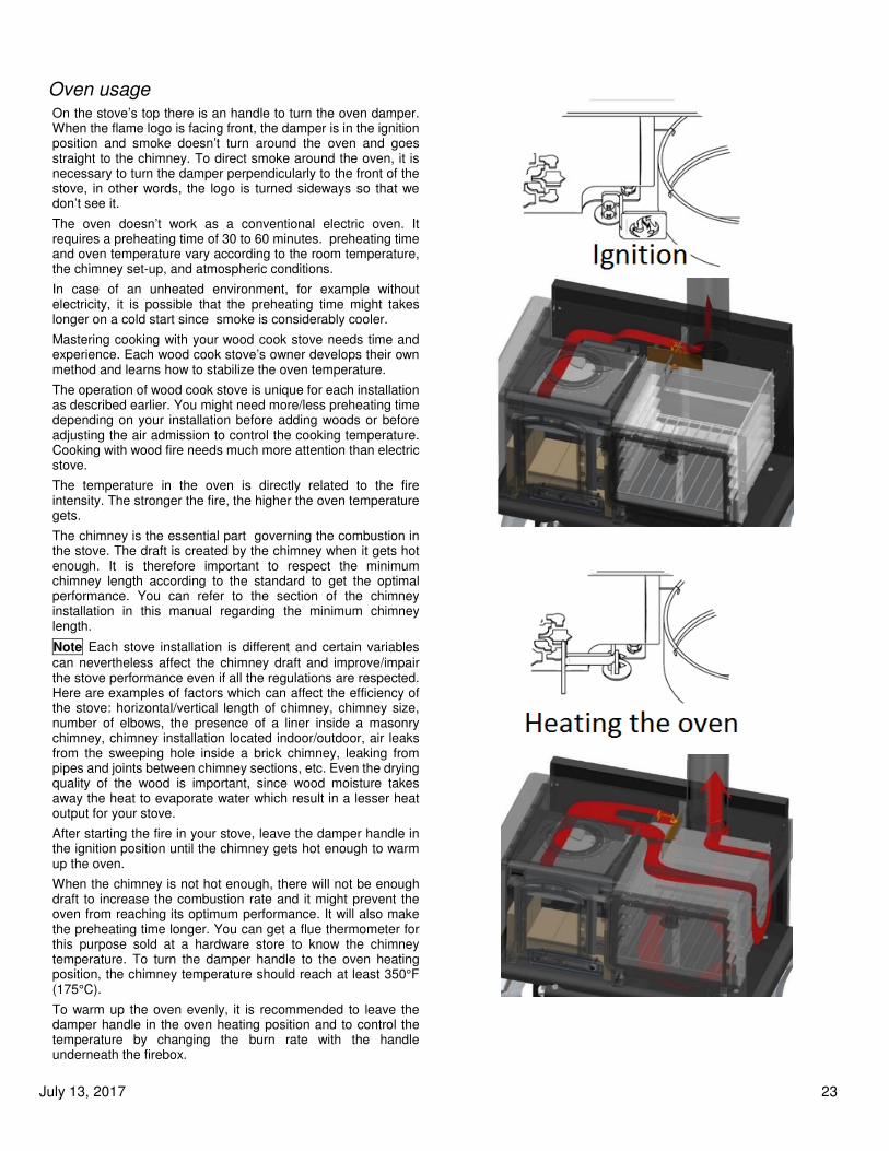
Oven usage On the stove’s top there is an handle to turn the oven damper. When the flame logo is facing front, the damper is in the ignition position and smoke doesn’t turn around the oven and goes straight to the chimney. To direct smoke around the oven, it is necessary to turn the damper perpendicularly to the front of the stove, in other words, the logo is turned sideways so that we don’t see it.
The oven doesn’t work as a conventional electric oven. It requires a preheating time of 30 to 60 minutes. preheating time and oven temperature vary according to the room temperature, the chimney set-up, and atmospheric conditions.
In case of an unheated environment, for example without electricity, it is possible that the preheating time might takes longer on a cold start since smoke is considerably cooler.
Mastering cooking with your wood cook stove needs time and experience. Each wood cook stove’s owner develops their own method and learns how to stabilize the oven temperature.
The operation of wood cook stove is unique for each installation as described earlier. You might need more/less preheating time depending on your installation before adding woods or before adjusting the air admission to control the cooking temperature. Cooking with wood fire needs much more attention than electric stove.
The temperature in the oven is directly related to the fire intensity. The stronger the fire, the higher the oven temperature gets.
The chimney is the essential part governing the combustion in the stove. The draft is created by the chimney when it gets hot enough. It is therefore important to respect the minimum chimney length according to the standard to get the optimal performance. You can refer to the section of the chimney installation in this manual regarding the minimum chimney length.
Note Each stove installation is different and certain variables
can nevertheless affect the chimney draft and improve/impair the stove performance even if all the regulations are respected. Here are examples of factors which can affect the efficiency of the stove: horizontal/vertical length of chimney, chimney size, number of elbows, the presence of a liner inside a masonry chimney, chimney installation located indoor/outdoor, air leaks from the sweeping hole inside a brick chimney, leaking from pipes and joints between chimney sections, etc. Even the drying quality of the wood is important, since wood moisture takes away the heat to evaporate water which result in a lesser heat output for your stove.
After starting the fire in your stove, leave the damper handle in the ignition position until the chimney gets hot enough to warm up the oven.
When the chimney is not hot enough, there will not be enough draft to increase the combustion rate and it might prevent the oven from reaching its optimum performance. It will also make the preheating time longer. You can get a flue thermometer for this purpose sold at a hardware store to know the chimney temperature. To turn the damper handle to the oven heating position, the chimney temperature should reach at least 350°F (175°C).
To warm up the oven evenly, it is recommended to leave the damper handle in the oven heating position and to control the temperature by changing the burn rate with the handle underneath the firebox.

July 13, 2017 24
Thermometer The temperatures of the thermometers on the oven and warmer are approximate and can’t be used for accurate cooking temperature. We recommend using a cooking thermometer instead.
Since it is a wood cook stove, It is also possible that the oven’s cooking time might takes longer than the one indicated in a given recipe. Spending more time using it and getting experience with it, you will be able to estimate the cooking time with your oven.
Cleaning of the creosote build-up When the stove is burning, smoke travels around the oven. Fly ash and creosote might form deposit on the inside wall along the smoke travel path. This mixture of ashes and creosote functions as an insulating layer and might inhibit the heat transfer from the smoke to the oven. It is therefore necessary to clean up that area once in a while.
This stove is calibrated for very low particulate emissions. However, if ashes and creosote build-ups appear quickly, it is possible that:
• You burn other fuels then wood,
• The wood you use is frozen or too moist/dry with humidity
level above 20% or under 10%,
• You completely close the door too early/late after the
ignition to maintain a clean combustion,
• You have a chimney draft issue (see chimney
installation.)
• There is a leak around the door gasket, a problem with
the air intake or the air flow under the baffle is blocked
For the stove maintenance, there are 4 access points:
1) The 2 round lids on the hob which allow the cleaning of
the oven top
2) The little rectangular hatch located on the top right corner
of the hob which allows access to the right side of the
oven
3) A rectangular hatch is located directly under the oven
door which allow access to the bottom part of the stove.
This door is also convenient to remove creosote deposits
that might have fallen while cleaning up.
4) The chimney collar allows to reach the back of the oven.
Clean up procedure Make sure the stove is cold. Remove the two circular lids (1) on the hob and scratch the oven top surface. While doing so, try pushing the creosote debris on the stove’s right side. You can let the debris fall at the bottom of the unit’s right side since you will be able to reach the fallen creosote debris by the access hatch located under the oven door.
Open the rectangular top access hatch (2) Clean up the creosote accumulated on the right side and let it fall at the bottom.
In order to access more easily the back of the stove for cleaning, it is recommended to reach the back from the flue collar (4). It will therefore be necessary to remove the chimney section connected to the stove.
Once the 3 oven’s sides have been cleaned, unscrew the two nuts (5) holding the bottom access hatch (3) under the oven door and open it up. Clean up the bottom part of the oven and remove all the dirt buildup that might have previously fall there.
You can use a vacuum cleaner to remove the creosote debris. It is recommended to change the filter or keep one filter exclusively for cleaning creosote/ashes.

July 13, 2017 25
MAINTENANCE
Ash Removal Wood burning doesn’t usually completely transform wood into combustion gas. The leftover residues are called ashes and they must be removed from the combustion chamber to help oxygen circulation.
The ashes have to be removed periodically up to every 2 or 3 days during intensive burning period. Never leave excessive accumulation in the combustion chamber because it can reduce the firebox volume and prevent the air supply from reaching the logs. As a result, this can affect considerably the performance of your stove.
Remove ashes excess when it gets 3 to 4 inches deep in your firebox. Note that the fire must have been put out and the stove must be cool enough for cleaning. You can leave an ash bed approximately 1 inch deep at the bottom of the firebox to help maintain a hot charcoal bed.
The best time to remove ashes is after a long heating period like in the morning when the stove is relatively cold enough to manipulate ashes and the chimney is still hot. The hot chimney draft will then vacuum the dust inside the stove.
To clean ashes from the combustion chamber, you must have the following tools.
• Ash shovel;
• Ash brush;
• A metal bucket with an airtight lid or other container made for this purpose.
Some embers are mixed with ashes and they could still catch fire in a few minutes or a few days. It is very important that the metal lid is airtight. The bucket must be put on a non-combustible tile or brick.
Ash Disposal Some embers can still catch fire long after the fire is deemed quenched. If embers have enough oxygen, they can stay lit for minuts or even for a few days.
It’s mandatory to store ashes:
• In a metal container with an airtight metal lid and firmly closed;
• Outside the house on a non-combustible material such as gravels, concrete and bricks;
• Far enough from any combustible material;
• Far enough from any inflammable liquid and vapor.
Before the ashes are discarded or buried in the soil, they should be retained in a closed container until they get thoroughly cooled and completely extinguished.
NEVER PUT TRASHES IN THE ASH CONTAINER.
Creosote Formation When wood is incompletely burned, it produces tar and other organic vapors, which condensate as creosote. The creosote vapor condenses on the relatively cold flue walls. As a result, creosote residue accumulates on the flue lining. The creosote could be in forms of tarry liquid, dust, soot or crystallized deposit. This creosote makes an extremely hot fire when ignited and it is the principal cause of chimney fire.
The chimney pipe and chimney should be inspected at least once a week during the first several months to determine the sweeping frequency
Contact your local fire authority to know how to handle a chimney fire.
Chimney Inspection Wood moisture, wood type, combustion quality are some factors that can influence the creosote buildup speed in the chimney pipes.
The chimney and the chimney pipes must be inspected at least once every two months during the heating season. You can contact a chimney sweeper to evaluate the sweeping frequency required. You can sweep the chimney yourself. To do so, extinguish the wood stove and wait until it cools down. Thereafter, remove the chimney collar screws and the stove collar screws to inspect the chimney pipe. Look inside the chimney with a flashlight. For a masonry chimney, it is possible to inspect inside the flue by removing at first the bottom steel flue plug. Afterward, you should be able to insert a small mirror in the chimney lookout to conduct your inspection. Don’t forget to put back the flue plug. For an outdoor factory built chimney, open the chimney cap at the bottom of the chimney. It is better to do an inspection during the daytime during a sunny day.
If there is a creosote buildup of 1/8 inch (3 mm) or more , if the chimney diameter appears smaller and/or if you cannot see the chimney cap, It’s a sign of an important creosote accumulation which will require a chimney sweeping.
Chimney Sweeping Chimney sweeping needs special tools such as fiberglass rod and a chimney brush of proper diameter.
In order to sweep the chimney, you will need to climb on the roof top to remove the chimney cap. If the chimney is taller then 5 feet above the roof it might be necessary to remove a chimney section.
If you are not comfortable doing it, we recommend calling a professional chimney sweeper certified by the APC in Quebec, the WETT in the rest of Canada or by the NFI in the United States.
July 13, 2017 26
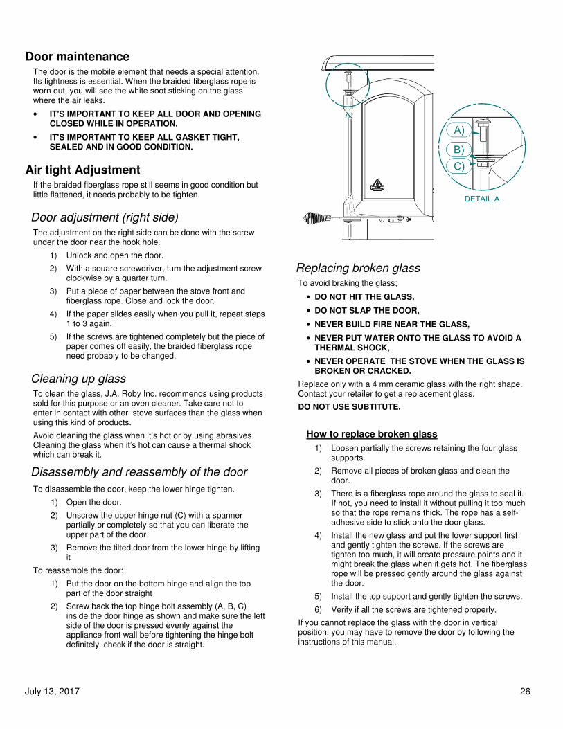
Door maintenance The door is the mobile element that needs a special attention. Its tightness is essential. When the braided fiberglass rope is worn out, you will see the white soot sticking on the glass where the air leaks.
• IT'S IMPORTANT TO KEEP ALL DOOR AND OPENING CLOSED WHILE IN OPERATION.
• IT'S IMPORTANT TO KEEP ALL GASKET TIGHT, SEALED AND IN GOOD CONDITION.
Air tight Adjustment If the braided fiberglass rope still seems in good condition but little flattened, it needs probably to be tighten.
Door adjustment (right side) The adjustment on the right side can be done with the screw under the door near the hook hole.
1) Unlock and open the door.
2) With a square screwdriver, turn the adjustment screw clockwise by a quarter turn.
3) Put a piece of paper between the stove front and fiberglass rope. Close and lock the door.
4) If the paper slides easily when you pull it, repeat steps 1 to 3 again.
5) If the screws are tightened completely but the piece of paper comes off easily, the braided fiberglass rope need probably to be changed.
Cleaning up glass To clean the glass, J.A. Roby Inc. recommends using products sold for this purpose or an oven cleaner. Take care not to enter in contact with other stove surfaces than the glass when using this kind of products.
Avoid cleaning the glass when it’s hot or by using abrasives. Cleaning the glass when it’s hot can cause a thermal shock which can break it.
Disassembly and reassembly of the door
To disassemble the door, keep the lower hinge tighten.
1) Open the door.
2) Unscrew the upper hinge nut (C) with a spanner partially or completely so that you can liberate the upper part of the door.
3) Remove the tilted door from the lower hinge by lifting it
To reassemble the door:
1) Put the door on the bottom hinge and align the top part of the door straight
2) Screw back the top hinge bolt assembly (A, B, C) inside the door hinge as shown and make sure the left side of the door is pressed evenly against the appliance front wall before tightening the hinge bolt definitely. check if the door is straight.
Replacing broken glass To avoid braking the glass;
• DO NOT HIT THE GLASS,
• DO NOT SLAP THE DOOR,
• NEVER BUILD FIRE NEAR THE GLASS,
• NEVER PUT WATER ONTO THE GLASS TO AVOID A THERMAL SHOCK,
• NEVER OPERATE THE STOVE WHEN THE GLASS IS BROKEN OR CRACKED.
Replace only with a 4 mm ceramic glass with the right shape. Contact your retailer to get a replacement glass.
DO NOT USE SUBTITUTE.
How to replace broken glass
1) Loosen partially the screws retaining the four glass supports.
2) Remove all pieces of broken glass and clean the door.
3) There is a fiberglass rope around the glass to seal it. If not, you need to install it without pulling it too much so that the rope remains thick. The rope has a self-adhesive side to stick onto the door glass.
4) Install the new glass and put the lower support first and gently tighten the screws. If the screws are tighten too much, it will create pressure points and it might break the glass when it gets hot. The fiberglass rope will be pressed gently around the glass against the door.
5) Install the top support and gently tighten the screws.
6) Verify if all the screws are tightened properly.
If you cannot replace the glass with the door in vertical position, you may have to remove the door by following the instructions of this manual.

July 13, 2017 27
Fiberglass rope replacement When it is impossible to adjust the door because of the flattened fiberglass rope, it is the time to change it. When the rope is damaged, you also have to replace it.
Use a ½ inch (12.7mm) braided round fiberglass rope (available in some hardware store).
To install the new fiberglass rope, we recommend detaching the door from the stove. Please see the section « Disassembly and reassembly of door » in this manual.
Fiberglass rope preparation
1) Remove the worn fiberglass rope and take care cleaning the groove of any leftover pieces of fiber or latex.
2) Take the frayed end of the fiberglass rope and push the loose fiber inside the end of the rope to put it together
3) Add a small amount of high temperature latex or silicone at the end of the fiberglass rope to make a clean end.
4) Starting from the lower corner near the hinge, put the fiberglass rope around the groove without giving any tension and measure the length of the rope.
5) Add ½ inch to the length measured in step 4 and repeat the step 2 & 3 for the new rope end.
Fiberglass rope installation
1) Put high temperature latex inside the clean groove in order to glue the fiberglass rope.
2) Starting from the lower corner near the hinge, put the fiberglass rope into the groove without giving any tension.
3) Align the two fiberglass rope ends perpendicularly and put some high temperature latex in between.
4) Let dry the high temperature latex for at least 48 hours. Put the door back on the hinges and readjust the tightness.
IN CASE OF CHIMNEY FIRE CONTACT YOUR LOCAL AUTHORITY TO KNOW WHAT TO DO IN CASE OF CHIMNEY FIRE AND BE SURE TO KNOW PROCEDURE IN CASE OF CHIMNEY FIRE.
1. Close all door, the air intakes and the damper.
2. Water the combustible materials around the stove.
3. Trigger an alarm and leave the house, if necessary, call the fire department.
4. Don’t interact with the pipes before the fire is completely extinguished.
Do not use the chimney before inspection or necessary repairs.
.
July 13, 2017 28
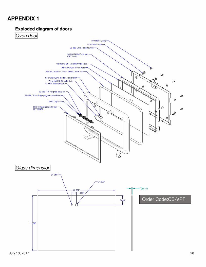
APPENDIX 1
Exploded diagram of doors
Oven door
Glass dimension
Order Code:CB-VPF

July 13, 2017 29
Square Stove door
Glass Dimension
Order Code: CB-VPC
July 13, 2017 30
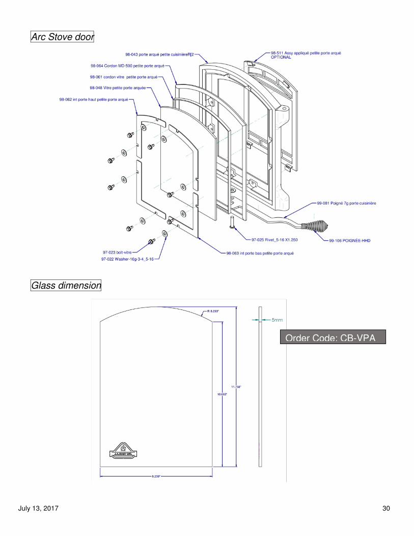
Arc Stove door
Glass dimension
Order Code: CB-VPA

July 13, 2017 31
Reservoir Door
Glass dimension
Order Code : CB-VPR

July 13, 2017 32
APPENDIX 2
Manuel d’installation et d’utilisation du réservoir à eau optionnel Installation and operation manual of the optional water tank
Le réservoir décoratif de J.A. Roby ajoute une touche d’esthétisme à votre cuisinière tout en complétant votre ensemble de cuisine. Comme attendu, le réservoir permet de garder une source d’eau chaude à portée de main pour votre maisonnée.
Note : Le réservoir n’est pas conçu pour faire bouillir l’eau ni pour réchauffer l’eau rapidement. Il ne sert qu’à maintenir la température de l’eau sur une période prolongée.
Attention : Pour remplir le réservoir d’eau chaude J.A. Roby préconise l’utilisation d’une bouilloire conventionnelle en métal placée directement sur le dessus du poêle
The J.A. Roby’s decorative water tank adds a touch of aesthetic to your cook stove while completing your kitchen set. As expected, it also provides an handy source of warm water for your household.
Note: The water tank is not conceived to boil water nor to warm it up quickly. It’s only purpose is to maintain the temperature of the water on an extended period.
Attention: To fill the water tank, J.A. Roby recommends using a standard metal kettle placed directly atop of the cook stove hob

July 13, 2017 33
Installation du réservoir
1) Visser partiellement les 4 vis
(A) fournies avec le réchaud
de façons à laisser
suffisamment de jeu pour
pouvoir accrocher ce dernier
les vis
2) Accrocher le réchaud sur les 4
vis en passant chacune
d’entre elles dans les 4
espaces du réchaud prévus à
cet effet
3) Appuyer le réservoir a eau sur
les 4 vis puis serrer les vis
complètement
X 4
Installation du réservoir
1) Screw partially the 4 screws (A)
provided with the water tank.
Keep enough clearance in order
to hang the water tank on them
2) Hang the water tank on the 4
screws by passing each one of
them in the waters tank’s
spaces provided to that effect
3) Support the water tank on the
screws and tighten them
completely
X 4
July 13, 2017 34
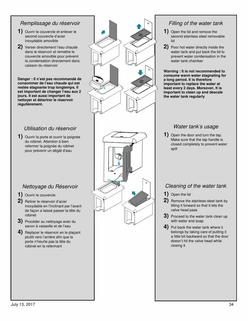
Remplissage du réservoir
1) Ouvrir le couvercle et enlever le
second couvercle d’acier
inoxydable amovible
2) Verser directement l’eau chaude
dans le réservoir et remettre le
couvercle amovible pour prévenir
la condensation directement dans
caisson du réservoir
Danger : Il n’est pas recommandé de consommer de l’eau chaude qui est restée stagnante trop longtemps. Il est important de changer l’eau aux 2 jours. Il est aussi important de nettoyer et détartrer le réservoir régulièrement.
Utilisation du réservoir
1) Ouvrir la porte et ouvrir la poignée
du robinet. Attention à bien
refermer la poignée du robinet
pour prévenir un dégât d’eau
Nettoyage du Réservoir
1) Ouvrir le couvercle
2) Retirer le réservoir d’acier
inoxydable en l’inclinant par l’avant
de façon a laissé passer la tête du
robinet
3) Procéder au nettoyage avec du
savon à vaisselle et de l’eau
4) Replacer le réservoir en le plaçant
plutôt vers l’arrière afin que la
porte n’heurte pas la tête du
robinet en la refermant
Filling of the water tank
1) Open the lid and remove the
second stainless steel removable
lid
2) Poor hot water directly inside the
water tank and put back the lid to
prevent water condensation in the
water tank chamber
Warning : It is not recommended to consume warm water stagnating for a long period. It is therefore important to replace the water at least every 2 days. Moreover, It is important to clean up and descale the water tank regularly
Water tank’s usage
1) Open the door and turn the tap.
Make sure that the tap handle is
closed completely to prevent water
spill
Cleaning of the water tank
1) Open the lid
2) Remove the stainless-steel tank by
tilting it forward so that it lets the
valve head pass
3) Proceed to the water tank clean up
with water and soap
4) Put back the water tank where it
belongs by taking care of putting it
a little bit backward so that the door
doesn’t hit the valve head while
closing it

July 13, 2017 35
APPENDIX 3
Replaceable parts
• Bricks
• Door glass
• Spring Handle
• Stove Door with handle
• Flat fiber glass rope (around glass)
• Round fiberglass rope
• Ash Plug
• Slotted Brick Washer
Call your stove seller representative to order parts.
July 13, 2017 36
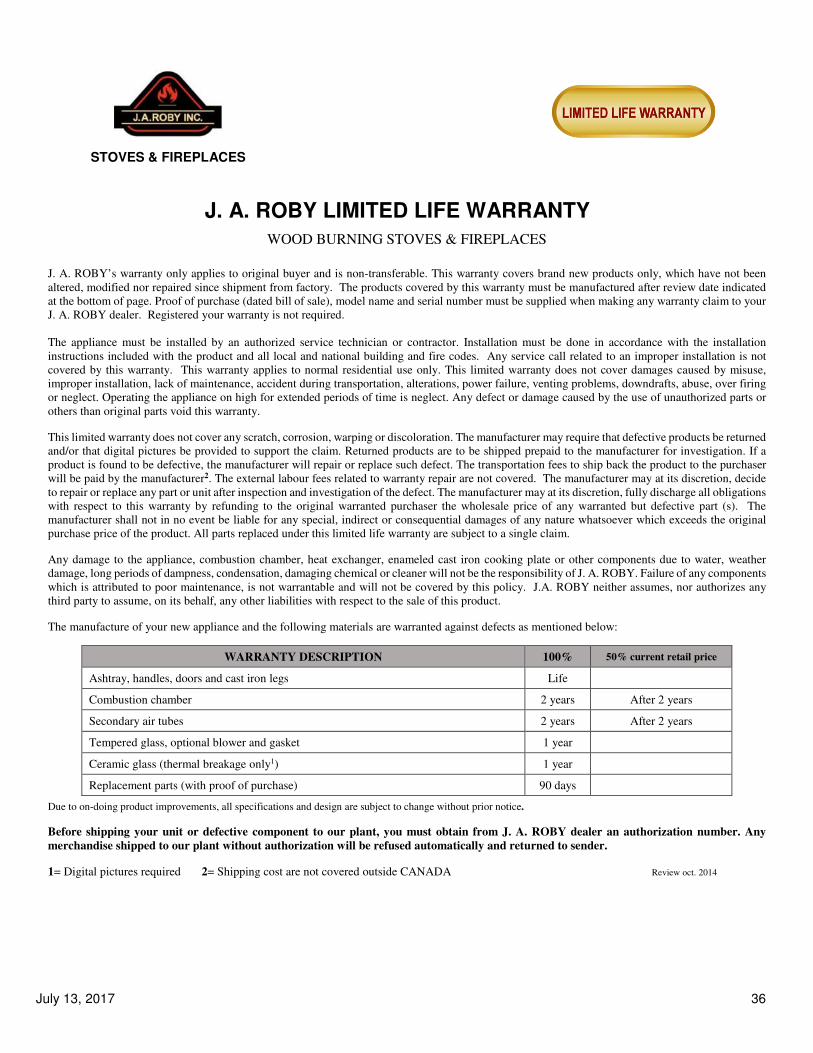
J. A. ROBY LIMITED LIFE WARRANTY
WOOD BURNING STOVES & FIREPLACES
J. A. ROBY’s warranty only applies to original buyer and is non-transferable. This warranty covers brand new products only, which have not been
altered, modified nor repaired since shipment from factory. The products covered by this warranty must be manufactured after review date indicated
at the bottom of page. Proof of purchase (dated bill of sale), model name and serial number must be supplied when making any warranty claim to your
J. A. ROBY dealer. Registered your warranty is not required.
The appliance must be installed by an authorized service technician or contractor. Installation must be done in accordance with the installation
instructions included with the product and all local and national building and fire codes. Any service call related to an improper installation is not
covered by this warranty. This warranty applies to normal residential use only. This limited warranty does not cover damages caused by misuse,
improper installation, lack of maintenance, accident during transportation, alterations, power failure, venting problems, downdrafts, abuse, over firing
or neglect. Operating the appliance on high for extended periods of time is neglect. Any defect or damage caused by the use of unauthorized parts or
others than original parts void this warranty.
This limited warranty does not cover any scratch, corrosion, warping or discoloration. The manufacturer may require that defective products be returned
and/or that digital pictures be provided to support the claim. Returned products are to be shipped prepaid to the manufacturer for investigation. If a
product is found to be defective, the manufacturer will repair or replace such defect. The transportation fees to ship back the product to the purchaser
will be paid by the manufacturer2. The external labour fees related to warranty repair are not covered. The manufacturer may at its discretion, decide
to repair or replace any part or unit after inspection and investigation of the defect. The manufacturer may at its discretion, fully discharge all obligations
with respect to this warranty by refunding to the original warranted purchaser the wholesale price of any warranted but defective part (s). The
manufacturer shall not in no event be liable for any special, indirect or consequential damages of any nature whatsoever which exceeds the original
purchase price of the product. All parts replaced under this limited life warranty are subject to a single claim.
Any damage to the appliance, combustion chamber, heat exchanger, enameled cast iron cooking plate or other components due to water, weather
damage, long periods of dampness, condensation, damaging chemical or cleaner will not be the responsibility of J. A. ROBY. Failure of any components
which is attributed to poor maintenance, is not warrantable and will not be covered by this policy. J.A. ROBY neither assumes, nor authorizes any
third party to assume, on its behalf, any other liabilities with respect to the sale of this product.
The manufacture of your new appliance and the following materials are warranted against defects as mentioned below:
WARRANTY DESCRIPTION 100% 50% current retail price
Ashtray, handles, doors and cast iron legs Life
Combustion chamber 2 years After 2 years
Secondary air tubes 2 years After 2 years
Tempered glass, optional blower and gasket 1 year
Ceramic glass (thermal breakage only1) 1 year
Replacement parts (with proof of purchase) 90 days
Due to on-doing product improvements, all specifications and design are subject to change without prior notice.
Before shipping your unit or defective component to our plant, you must obtain from J. A. ROBY dealer an authorization number. Any
merchandise shipped to our plant without authorization will be refused automatically and returned to sender.
1= Digital pictures required 2= Shipping cost are not covered outside CANADA Review oct. 2014
STOVES & FIREPLACES