manual lxcos v2.1 en · changed i-setpoint potentiometer in sr2 mode. ... 8 loss of current sensing...
TRANSCRIPT
LXCOS Voltage regulator for generators
Instruction Manual V2.1
Product version V1.4.3.0
Marine approved
Manual V2.1 Page 2 of 20
Warnings And Commissioning information
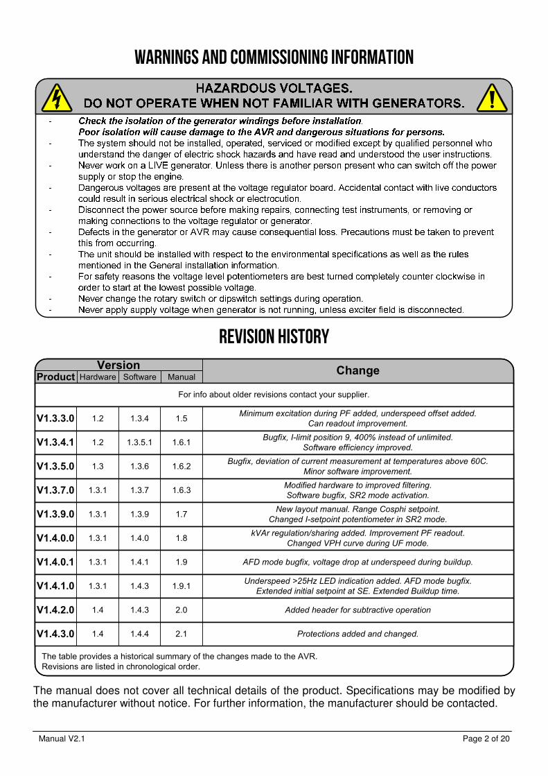
Revision history
Version ChangeProduct Hardware Software Manual
V1.3.3.0 1.2 1.3.4 1.5Minimum excitation during PF added, underspeed offset added.
Can readout improvement.
V1.3.4.1 1.2 1.3.5.1 1.6.1Bugfix, I-limit position 9, 400% instead of unlimited.
Software efficiency improved.
V1.3.5.0 1.3 1.3.6 1.6.2Bugfix, deviation of current measurement at temperatures above 60C.
Minor software improvement.
V1.3.7.0 1.3.1 1.3.7 1.6.3Modified hardware to improved filtering.
Software bugfix, SR2 mode activation.
V1.3.9.0 1.3.1 1.3.9 1.7New layout manual. Range Cosphi setpoint.
Changed I-setpoint potentiometer in SR2 mode.
V1.4.0.0 1.3.1 1.4.0 1.8kVAr regulation/sharing added. Improvement PF readout.
Changed VPH curve during UF mode.
V1.4.0.1 1.3.1 1.4.1 1.9 AFD mode bugfix, voltage drop at underspeed during buildup.
The table provides a historical summary of the changes made to the AVR.Revisions are listed in chronological order.
For info about older revisions contact your supplier.
V1.4.1.0 1.3.1 1.4.3 1.9.1Underspeed >25Hz LED indication added. AFD mode bugfix.
Extended initial setpoint at SE. Extended Buildup time.
V1.4.2.0 1.4 1.4.3 2.0 Added header for subtractive operation
V1.4.3.0 1.4 1.4.4 2.1 Protections added and changed.
The manual does not cover all technical details of the product. Specifications may be modified by the manufacturer without notice. For further information, the manufacturer should be contacted.
Manual V2.1 Page 3 of 20
Table of contents
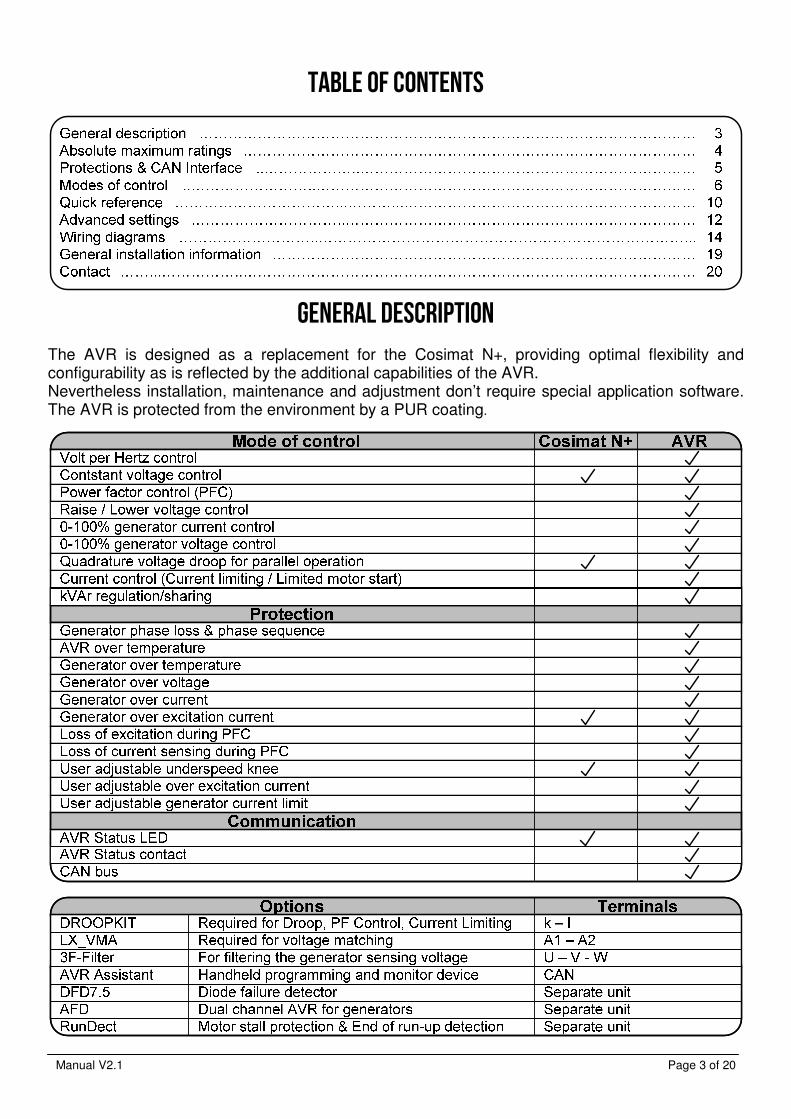
General description
The AVR is designed as a replacement for the Cosimat N+, providing optimal flexibility and configurability as is reflected by the additional capabilities of the AVR. Nevertheless installation, maintenance and adjustment don’t require special application software. The AVR is protected from the environment by a PUR coating.

Manual V2.1 Page 4 of 20
Absolute maximum rating
Manual V2.1 Page 5 of 20
Protections
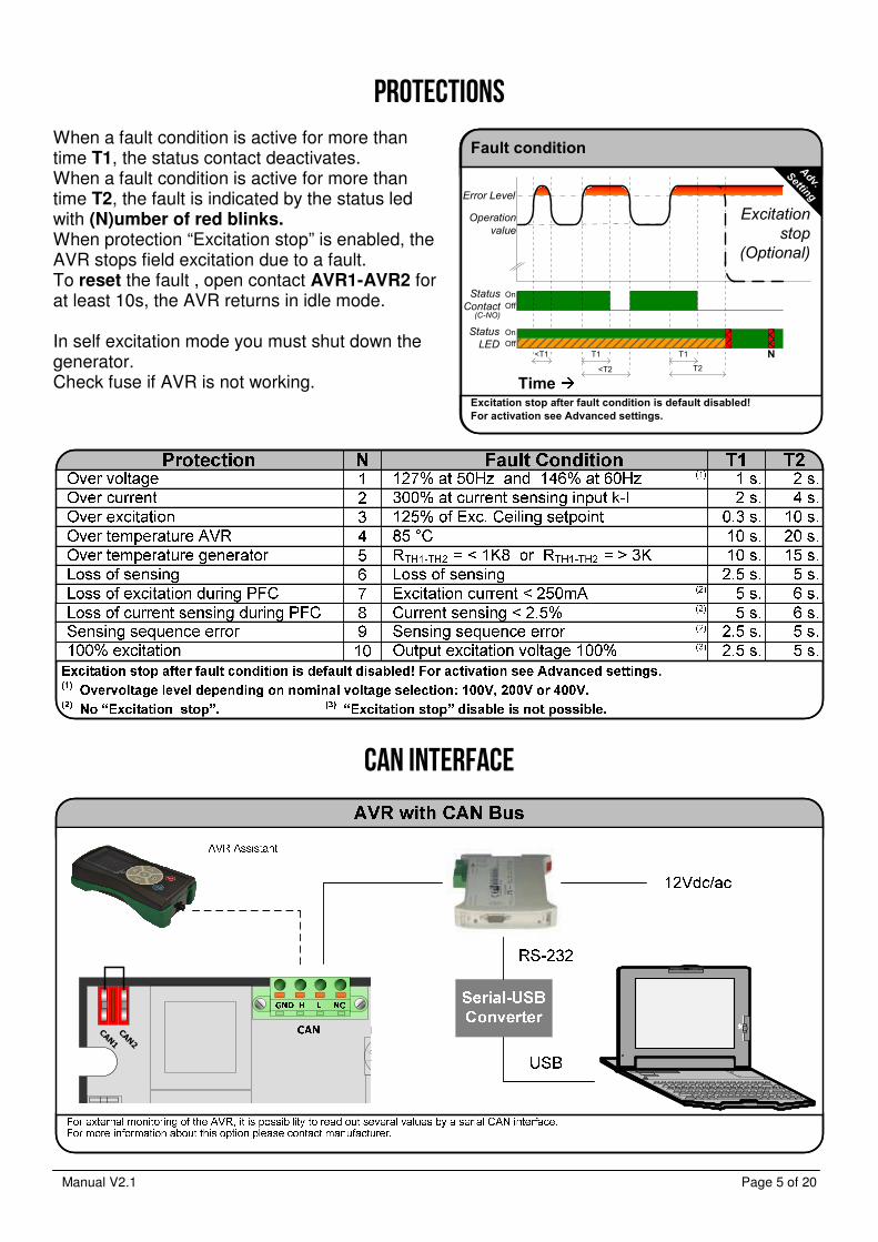
When a fault condition is active for more than time T1, the status contact deactivates. When a fault condition is active for more than time T2, the fault is indicated by the status led with (N)umber of red blinks. When protection “Excitation stop” is enabled, the AVR stops field excitation due to a fault. To reset the fault , open contact AVR1-AVR2 for at least 10s, the AVR returns in idle mode. In self excitation mode you must shut down the generator. Check fuse if AVR is not working.
CAN Interface
CAN1
CAN2
Fault condition
Time
Status
LED
Status
Contact
<T1
Error Level
On
Off
On
Off
(C-NO)
Excitation stop after fault condition is default disabled!
For activation see Advanced settings.
Operation
value
T2
T1
<T2
T1 N
Excitation
stop
(Optional)
Adv.
Setting
Manual V2.1 Page 6 of 20
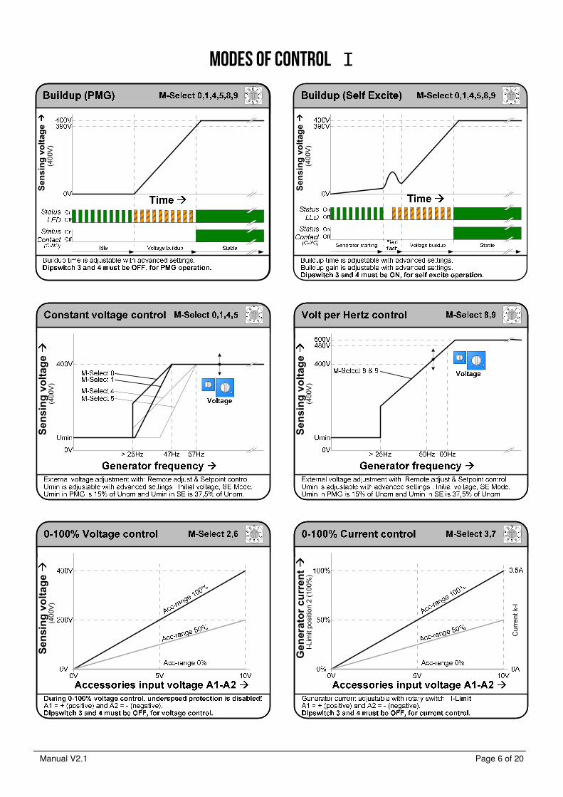
Modes of control I
Sensing voltage
(400
V)
1
46
9
Sensing voltage
(400
V)
1
46
9
Sensing voltage
1
46
9(4
00V
)
Sensing voltage
(400
V)
1
46
9
Generator current
I-Li
mit
posi
tion
2 (1
00%
)
Cur
rent
k-l
1
46
9
Sensing voltage
(400
V)
1
46
9

Manual V2.1 Page 7 of 20
Modes of control II
Sensing voltage
(400
V)
1
46
9
Sensing voltage
(400
V)
1
46
9
Sensing voltage
(400
V)
1
46
9
Generator voltage
1
46
9
Adv.
Setting
1,
,1
10,1
15,1
20,1
25,1
30,1
35,1
40,1
45
Generator currrent
Cur
rent
k-l
1
46
9
1
46
9
Current
32
78
Generator
Voltage
Manual V2.1 Page 8 of 20
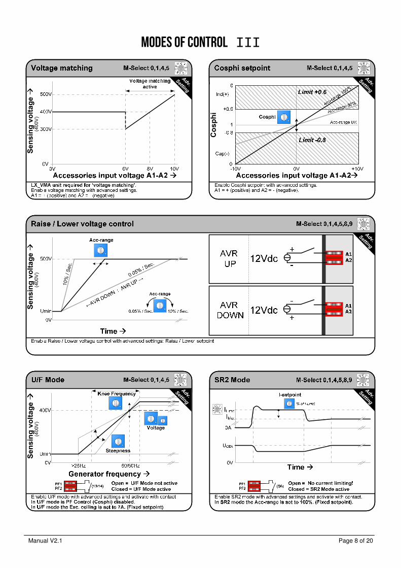
Modes of control III
Cosphi
1
46
9
Adv.
Setting
Sensing voltage
(400
V)
32
78
Adv.
Setting
Sensing voltage
(400
V)
10%
/ S
ec.
1
46
9
Adv.
Setting
1
46
9
1
46
9
Adv.
Setting
Sensing voltage
(400
V)
1
46
9
Adv.
Setting

Manual V2.1 Page 9 of 20
Modes of control IV
Minim
um excitation
(Fie
ld c
urre
nt c
ontr
ol)
1
46
9
Adv.
Setting
Sensing voltage
(400
V)
1
46
9
Adv.
Setting
1
46
9
Adv.
Setting
Excitation
1
46
9
Acc-range 100%
Adv.
Setting
1
46
9
Adv.
Setting
1
46
9
Adv.
Setting

Manual V2.1 Page 10 of 20
Quick reference I
M-Select
Constant voltage control0
Constant voltage control1
0-100% Voltage control with A1-A22
0-100% Current control with A1-A23
Constant voltage control4
Constant voltage control5
0-100% Voltage control with A1-A26
0-100% Current control with A1-A27
VPH (Volt per Hertz) control8
47 Hz 57Hz 8 V/Hz
47 Hz 57Hz 16 V/Hz
- - -
47 Hz 57Hz 8 V/Hz
57 Hz 47Hz 8 V/Hz
57 Hz 47Hz 16 V/Hz
- - -
57 Hz 47Hz 8 V/Hz
- - 8 V/Hz
VPH (Volt per Hertz) control9 - - 8 V/Hz
Linked Open (400V)
SlopeTH1 – TH2Underspeed
Normal mode
0% 100% 0% 100%
SR2 mode
Acc. Range I-setpoint
Acc. Range / I-setpoint
% of I-Limit% of input A1-A2
0 1
3
4
2
56
78
9
Sensing
Sensing
U-V-Wclockwise
100V 200V 400V
Coarse
88V 132V
Coarse
158V 253V
Coarse
300V 500V
Modes of Control
Exciter
0..7Adc
A
V
-
++
-Check
(Formula)
Minimum field resistance
Formula
Supply input x √2 (VDC)Field resistance (Ω) ≥
20
Max. rating: Intermitted 15A < 10s.
Adv.
Setting
Error
Over voltage1
Over current2
Over excitation3
4 Over temperature AVR
5 Over temperature generator
6 Loss of sensing
7 Loss of excitation during PF control
8 Loss of current sensing during PF control
N
Voltage control
Current controlPF control
Underspeed (<25Hz)
Error: (n) numberof red blinks
GreenContinuous
OrangeBlink
RedContinuousGreen withRed blink
OrangeContinuous
Buildup
Green with Orange blink
Underspeed (>25Hz)VPH control
Cosphi / Steepness
Normal mode U/F mode
Cosphi Steepness
0.8Cap
0.6Ind
1
3V/Hz 17V/Hz
Adv.
Setting
Droop
0% 100%
Voltage
Coarse Fine
- + -1.5% +1.5%
Adv.
Setting
Stability
Prop. Gain
Int. time
- +
- +
( x Loop gain)
( x Loop gain)
Adv.
Setting
Adv.
Setting
I-Limit
0 = 60%1 = 80%2 = 100%3 = 125%4 = 150%
5 = 175%6 = 200%7 = 250%8 = 300%9 = Unlimited
0 1
3
4
2
56
78
9
Normal mode U/F mode
Exc. Ceiling Knee frequency
1A 15A 30Hz 60Hz
Exc. Ceiling / Knee frequency
/ Cosphi-2Adv.
Setting
Adv.
SettingCosphi-2
setpoint
Cosphi-2
0.8Cap
0.6Ind
1
Status Led
IdleGreenBlink
Accessories input
Max. rating: -13V .. +13V
-+
Voltage matchCosphi setpointRaise/Lower
Advanced settings
(+6V .. +10V)(-10V .. +10V)(+12V / -12V)
Constant voltageVPH0..100% Voltage control0..100% Current control
M-Select
(-10V .. +10V)(-10V .. +10V)
(0V .. +10V)(0V .. +10V)
9
10
Sensing sequence error
100% excitation
Manual V2.1 Page 11 of 20
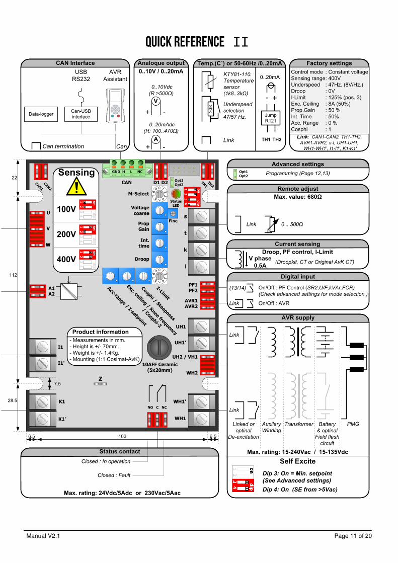
Quick reference II
M-Select
Voltage coarse
Prop Gain
Int. time
Droop
K1'
WH1'
UH2 / VH1
WH2
PF1PF2
k
l
s
t
AVR1AVR2
NO C NC
A1A2
V
Acc-range
/ I-setpoint
Exc. ceiling/ Knee frequency
/ Cosphi-2
Cosphi / Steepness
I-Limit
Fine
W
U
D1 D2CAN
WH1
UH1'
UH1
Opt1Opt2
I1'
I1
K1
10AFF Ceramic(5x20mm)
StatusLED
CAN1
CAN2
TH1TH2
GND H L NC
6.5 102 6.5
112
28.5
22
7.5
CAN Interface
AVR Assistant
Data-loggerCan-USBinterface
Can termination
USBRS232
Can
Analoque output
V
-+A
0..20mAdc
(R: 100..470Ω)
V
+ -
0..10Vdc
(R >500Ω)
Temp.(C˚) or 50-60Hz /0..20mA
>3K
Link
KTY81-110.
Temperature
sensor
(1k8..3kΩ)
Underspeed
selection
47/57 Hz.
Closed : Fault
Closed : In operation
Status contact
0..10V / 0..20mA
AVR supply
Link
Link
Linked or
optinal
De-excitation
Auxilary
Winding
Transformer Battery
& optinal
Field flash
circuit
PMG
Max. rating: 15-240Vac / 15-135Vdc
Digital input
Link On/Off : AVR
(13/14) On/Off : PF Control (SR2,U/F,kVAr,FCR)(Check advanced settings for mode selection )
Max. rating: 24Vdc/5Adc or 230Vac/5Aac
V phase
0.5A
Current sensing
(Droopkit, CT or Original AvK CT)
Droop, PF control, I-Limit
Factory settings
Link: CAN1-CAN2, TH1-TH2, AVR1-AVR2, s-t, UH1-UH1,
WH1-WH1’, I1-I1', K1-K1'
Remote adjust
Link
Max. value: 680Ω
0 .. 500Ω
- Measurements in mm.- Height is +/- 70mm.- Weight is +/- 1.4Kg.- Mounting (1:1 Cosimat-AvK)
Product information
0 1
3
4
2
5678
9
0 1
3
4
2
5678
9
Dip 3: On = Min. setpoint
(See Advanced settings)
Dip 4: On (SE from >5Vac)
Self Excite
Advanced settingsOpt1Opt2
Programming (Page 12,13)
+-
JumpR121
0..20mA
TH1 TH2
Z
Control modeSensing rangeUnderspeedDroopI-LimitExc. CeilingProp.GainInt. TimeAcc. RangeCosphi
: Constant voltage: 400V : 47Hz. (8V/Hz.): 0V: 125% (pos. 3): 8A (50%): 50 %: 50%: 0 %: 1
Sensing
100V
200V
400V
on
dip
1234
on
dip
1234
on
dip
1234
on
dip
1234
Manual V2.1 Page 12 of 20
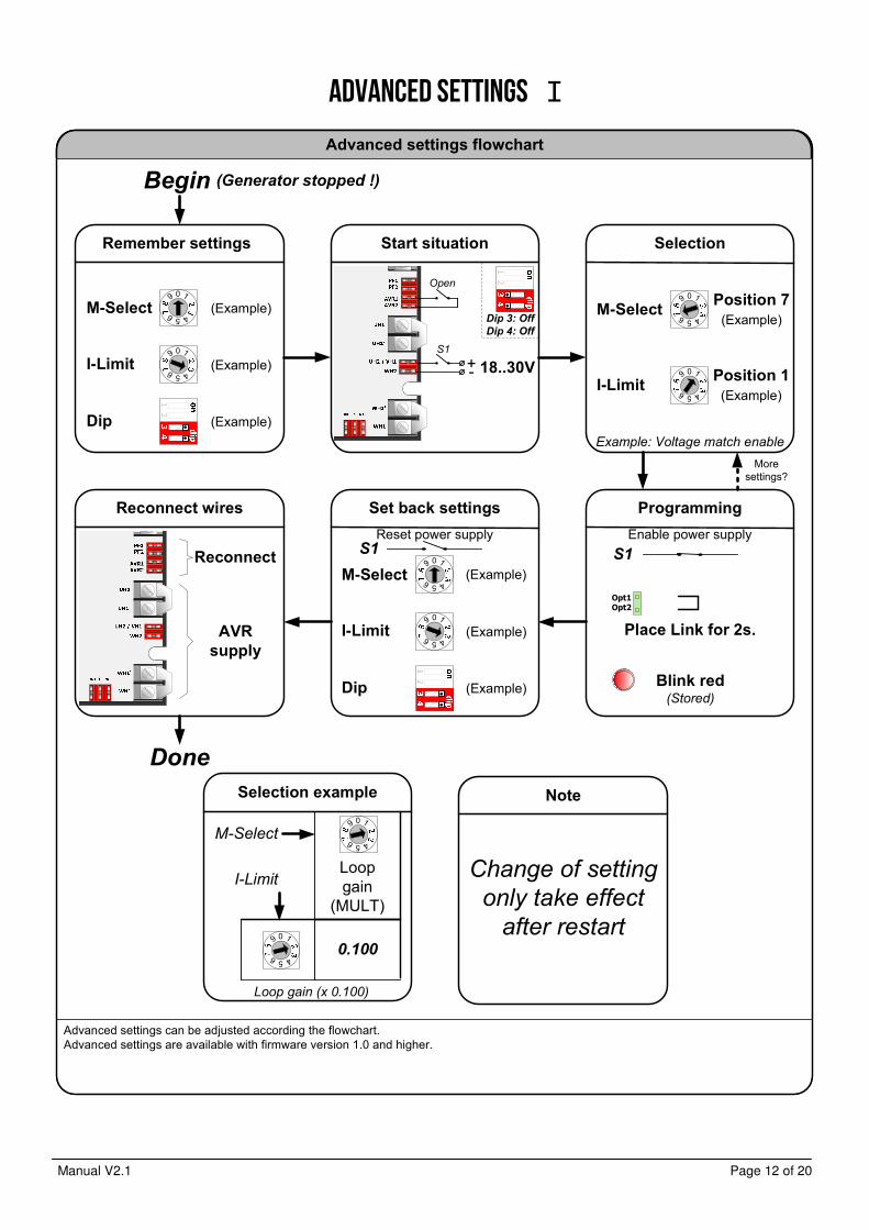
Advanced settings I
Advanced settings flowchart
Advanced settings can be adjusted according the flowchart.Advanced settings are available with firmware version 1.0 and higher.
Begin
Done
Moresettings?
(Generator stopped !)
Programming
Blink red(Stored)
Place Link for 2s.
Reconnect wires
AVR
supply
Remember settings
M-Select
I-Limit
Dip
0 1
456
9
0 1
456
9
Start situation
18..30V+-
S1
Dip 3: Off
Dip 4: Off
Set back settings
M-Select
I-Limit
Dip
0 1
456
9
0 1
456
9
Selection
Example: Voltage match enable
0 1
456
9
0 1
456
9
M-Select
I-Limit
Position 7
(Example)
Position 1
(Example)
(Example)
(Example)
(Example)
(Example)
(Example)
(Example)
Reconnect
Open
Opt1Opt2
Selection example
Loop gain (x 0.100)
0.1000 1
456
9
Loopgain
(MULT)
0 1
456
9
I-Limit
M-Select
Note
Change of setting
only take effect
after restart
S1
Enable power supplyS1
Reset power supply
Manual V2.1 Page 13 of 20
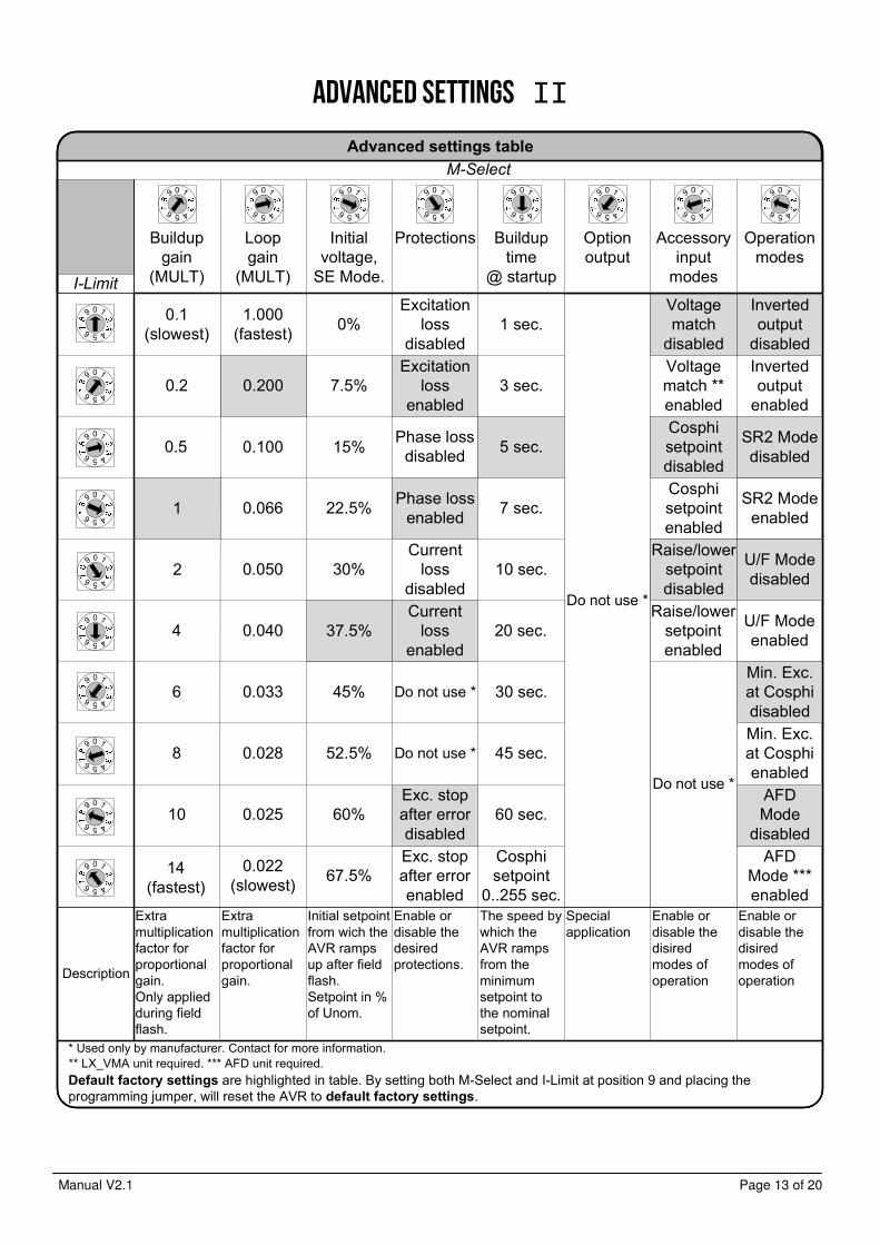
Advanced settings II
M-Select
I-Limit
Description
Extra multiplication factor for proportional gain. Only applied during field flash.
Extra multiplicationfactor for proportional gain.
Buildup gain
(MULT)
Loopgain
(MULT)
Initial setpoint from wich the AVR ramps up after field flash.Setpoint in % of Unom.
Enable or disable the desired protections.
The speed by which the AVR ramps from the minimum setpoint to the nominal setpoint.
Specialapplication
Enable or disable the disired modes of operation
Initialvoltage,
SE Mode.
Protections Buildup time
@ startup
Option output
Accessory input
modes
Operation modes
Enable or disable the disired modes of operation
0.1(slowest)
0.2
0.5
2
4
6
8
10
14(fastest)
1.000(fastest)
0.100
0.200
0.066
0.050
0.040
0.033
0.028
0.025
0.022(slowest)
1
0%
7.5%
37.5%
22.5%
30%
15%
45%
52.5%
60%
67.5%
Excitation loss
disabled
Current loss
disabled
Excitation loss
enabled
Current loss
enabled
Do not use *
Do not use *
Exc. stop after errorenabled
Exc. stop after errordisabled
1 sec.
3 sec.
7 sec.
10 sec.
20 sec.
30 sec.
45 sec.
60 sec.
Cosphi setpoint
0..255 sec.
5 sec.
Voltage match
disabled
Inverted output
disabled
Cosphi setpointdisabled
Do not use *
Voltage match ** enabled
Cosphi setpointenabled
Inverted output
enabled
Advanced settings table
* Used only by manufacturer. Contact for more information.
Default factory settings are highlighted in table. By setting both M-Select and I-Limit at position 9 and placing the programming jumper, will reset the AVR to default factory settings.
Raise/lowersetpointdisabled
Raise/lower setpointenabled
SR2 Modedisabled
U/F Modedisabled
Min. Exc.at Cosphidisabled
AFD Mode
disabled
SR2 Modeenabled
U/F Modeenabled
Min. Exc.at Cosphienabled
AFDMode ***enabled
** LX_VMA unit required. *** AFD unit required.
0 1
456
9
0 1
456
9
0 1
456
9
0 1
456
9
0 1
456
9
0 1
456
9
0 1
456
9
0 1
456
9
0 1
456
9
0 1
456
9
0 1
456
9 0 1
456
9 0 1
456
9 0 1
456
9 0 1
456
9 0 1
456
9 0 1
456
9 0 1
456
9
Do not use *
Phase loss enabled
Phase loss disabled
Manual V2.1 Page 14 of 20
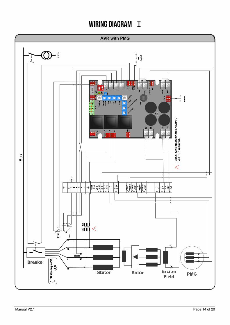
Wiring diagram I
AVR with PMG
Acc-range
Excitation ceiling
Cosphi
I-Limit
CAN1
CAN2
TH1
TH2
1 469
1 469
Manual V2.1 Page 15 of 20
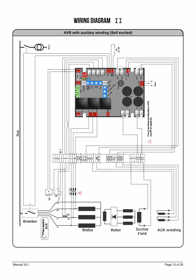
Wiring diagram II
AVR with auxilary winding (Self excited)
Acc-range
Excitation ceiling
Cosphi
I-Limit
CAN1
CAN2
TH1
TH2
1 469
1 469
Manual V2.1 Page 16 of 20
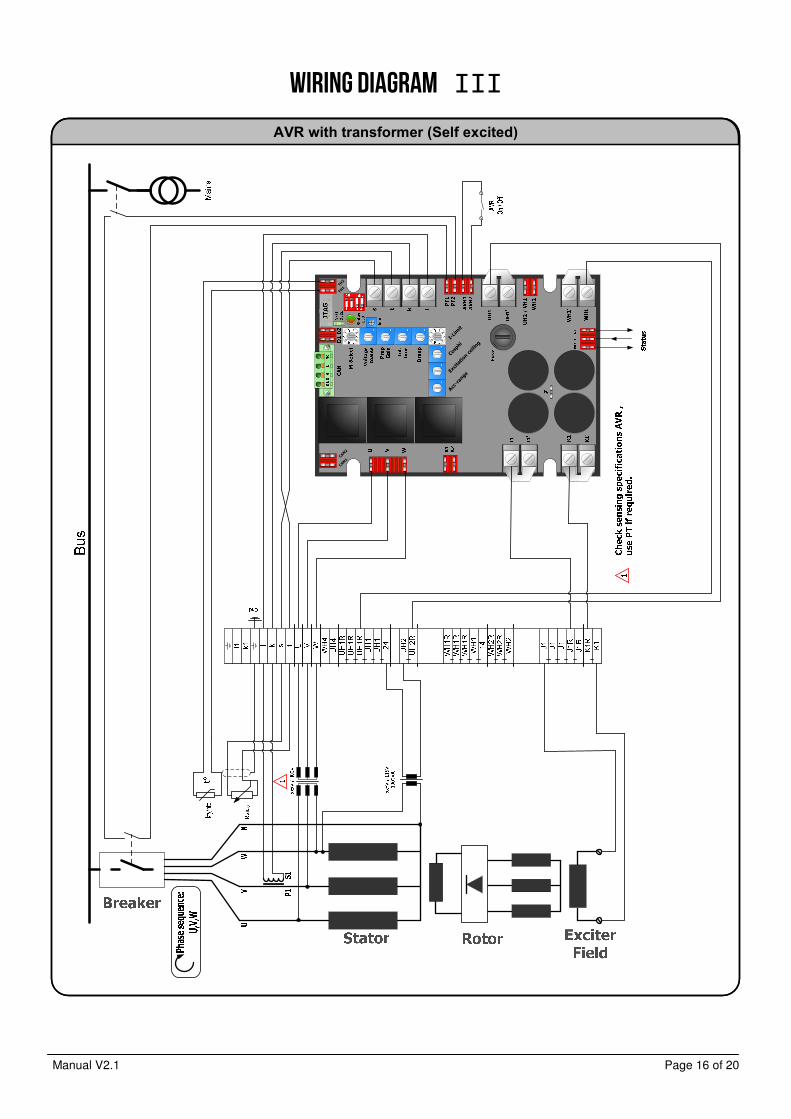
Wiring diagram III
AVR with transformer (Self excited)
Acc-range
Excitation ceiling
Cosphi
I-Limit
CAN1
CAN2
TH1
TH2
1 469
1 469
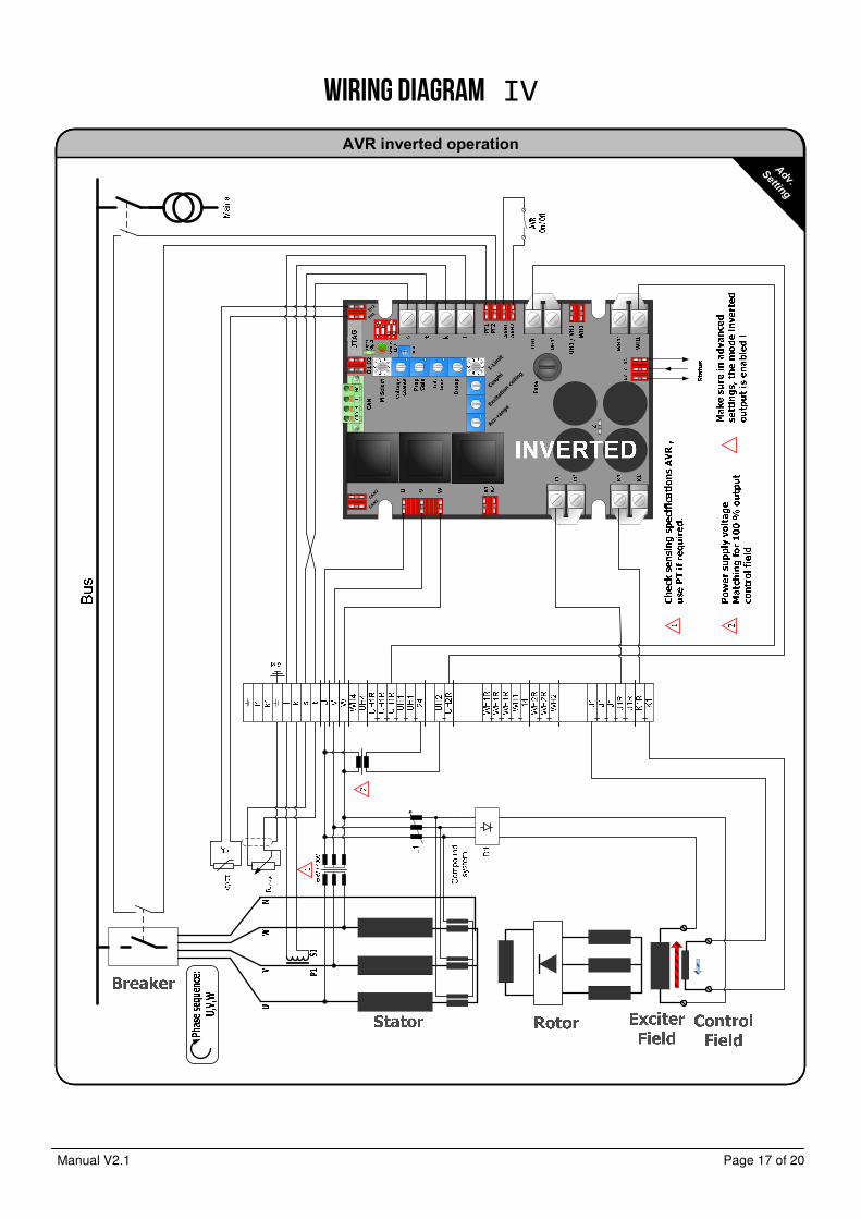
Manual V2.1 Page 17 of 20
Wiring diagram IV
AVR inverted operation
Adv.
Setting
Acc-rangeEx
citation ceiling
Cosphi
I-Limit
CAN1
CAN2
TH1
TH2
1 469
1 469
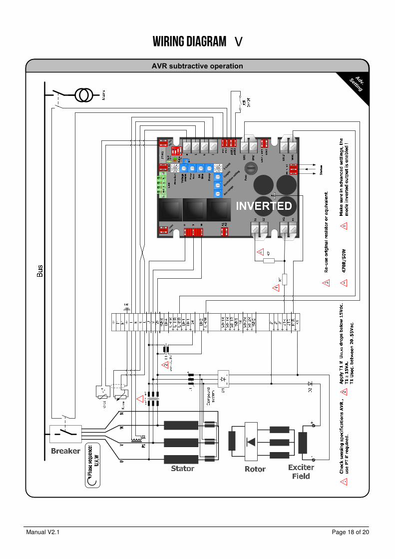
Manual V2.1 Page 18 of 20
Wiring diagram V
AVR subtractive operation
Adv.
Setting
Acc-range
Excitation ceiling
Cosphi
I-Limit
CAN1
CAN2
TH1
TH2
1 469
1 469
Manual V2.1 Page 19 of 20
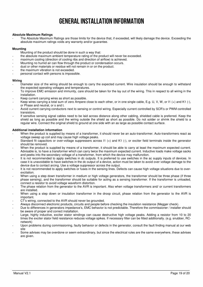
General installation information Absolute Maximum Ratings - The Absolute Maximum Ratings are those limits for the device that, if exceeded, will likely damage the device. Exceeding the
absolute maximum ratings voids any warranty and/or guarantee. Mounting
Mounting of the product should be done in such a way that: - the absolute maximum ambient temperature rating of the product will never be exceeded. - maximum cooling (direction of cooling ribs and direction of airflow) is achieved. - Mounting no humid air can flow through the product or condensation occurs. - dust or other materials or residue will not remain in or on the product. - the maximum vibration is not exceeded. - personal contact with persons is impossible. Wiring - Diameter size of the wiring should be enough to carry the expected current. Wire insulation should be enough to withstand
the expected operating voltages and temperatures. - To improve EMC emission and immunity, care should be taken for the lay out of the wiring. This in respect to all wiring in the
installation. - Keep current carrying wires as short as possible. - Keep wires carrying a total sum of zero Ampere close to each other, or in one single cable, E.g. U, V, W, or I1 (+) and K1 (-),
or Phase and neutral, or s and t. - Avoid current carrying conductors next to sensing or control wiring. Especially current controlled by SCR’s or PWM controlled
transistors. - If sensitive sensing signal cables need to be laid across distance along other cabling, shielded cable is preferred. Keep the
shield as long as possible and the wiring outside the shield as short as possible. Do not solder or shrink the shield to a regular wire. Connect the original shield to ground at one side with an as large as possible contact surface.
Additional installation information - When the product is supplied by means of a transformer, it should never be an auto-transformer. Auto-transformers react as
voltage sweep up coil and may cause high voltage peaks. - Standard fit capacitors or over-voltage suppressers across I1 (+) and K1 (-), or exciter field terminals inside the generator
should be removed. - When the product is supplied by means of a transformer, it should be able to carry at least the maximum expected current.
Advisable is, to have a transformer which can carry twice the maximum expected current. Inductive loads make voltage sacks and peeks into the secondary voltage of a transformer, from which the device may malfunction.
- It is not recommended to apply switches in dc outputs. It is preferred to use switches in the ac supply inputs of devices. In case it is unavoidable to have switches in the dc output of a device, action must be taken to avoid over voltage damage to the device due to contact arcing. Use a voltage suppressor across the output.
- It is not recommended to apply switches or fuses in the sensing lines. Defects can cause high voltage situations due to over-excitation.
- When using a step down transformer in medium or high voltage generators, the transformer should be three phase (if three phase sensing), and the transformer should be suitable for acting as a sensing transformer. If the transformer is unloaded, connect a resistor to avoid voltage waveform distortion.
- The phase relation from the generator to the AVR is important. Also when voltage transformers and/ or current transformers are installed.
- When using a step down or insulation transformer in the droop circuit, phase relation from the generator to the AVR is important.
- CT’s wiring, connected to the AVR should never be grounded. - Always disconnect electronic products, circuits and people before checking the insulation resistance (Megger check). - Due to differences in generators impedance’s, EMC behavior is not predictable. Therefore the commissioner / installer should
be aware of proper and correct installation. - Large, highly inductive, exciter stator windings can cause destructive high voltage peaks. Adding a resistor from 10 to 20
times the exciter stator field resistance reduces voltage spikes. If necessary filter can be fitted additionally. (e.g. snubber, RC-network)
- Upon problems during commissioning, faulty behavior or defects in the generator, consult the fault finding manual at our web site
- Some advises may be overdone or seem extraordinary, but since the electrical rules are the same everywhere, these advises are given.
Manual V2.1 Page 20 of 20
Contact
EMRI Electronics B.V. Manufacturer Morsestraat 10 6716 AH, Ede, Netherlands Tel: +31 (0)318 620 427 Fax: +31 (0)318 634 615 Website: www.emri.nl E-mail: [email protected]
ICELAND, Hafnarfjordur Rafeining ehf Tel: +354 565 3049 Fax: +354 565 3048 Website: www.rafeining.is
E-mail: [email protected]
POLAND, Gdynia An-Elec Sp. z o.o. Tel: +48 58 668 44 00 Fax: +48 58 668 44 66 Website: http://an-elec.pl E-mail: [email protected]
INDIA, Faridabad
Power Solutions Tel: +911 29404 1409 Fax:: +911 29404 1410 Website: www.psolindia.com E-mail: [email protected]
SOUTH AFRICA, Roodepoort
Yneldo Electronics Tel: +27(0)117637053 Fax: +27(0)117634212 Website: www.yneldo.com E-mail: [email protected]
POLAND, Szczezin-Mierzyn
Marel Serwis Tel: +48 91 48 58 388 Fax: +48 91 48 79 948 Website: www.marel.szczecin.pl E-mail: [email protected]
CHILE, Santiago Lucio Vicencio y CIA.LTDA Tel: +1-281-334-2904 Fax:: +1-832-221-5642 Website: www.luciovicencio.cl E-mail: [email protected]
NORWAY, Bergen Frydenbø Electric A/S Tel: +47 55 34 91 00 Fax: +47 55 34 91 10 Website: www.frydenbo.no
E-mail: [email protected]
SINGAPORE, Singapore Cyclect Electrical Engineering Tel: +65 6868 6013 Fax: +65 6863 6260 Website: www.cyclect.com.sg E-mail: [email protected]
THAILAND, Bang Lamung Semtec Maritime/Genetech Co.Ltd Tel: +66 38301262 Fax: +1-832-221-5642 Website: semtecmaritime.com/ Email: [email protected]
UNITED ARAB EMIRATES, Sharjah KDU Technical Services Tel: +971-6-5575480 Fax: +971-6-5575490 Website: www.kdutech.ae E-mail: [email protected]
SWEDEN, Kungälv Elektrisk Drivteknik EDT AB Tel: +46-705-28 20 60 Tel: +46-709-50 47 90 Website: www.edtab.se E-mail: [email protected]
GREECE, Piraeus Stavros Kassidiaris S.A. Tel: +30 210 4636000 Fax: +30 210 4624471 Website: www.kassidiaris.gr E-mail: [email protected]
CANARY ISLANDS, Las Palmas
Zamakona Yards Tel: +34 928467521 Fax: +34 928461233 Website: www.zamakonayards.com/ E-mail: [email protected]
UNITED KINGDOM, Stockton on Tees
MJR Controls Tel: +44 1642 762 151 Fax: +44 1642 762 502 Website: www.mjrcontrols.com Email: [email protected]
UNITED STATES, Kemah - Texas
Ramtec Marine Systems LLC Tel: +1-281-334-2904 Fax: +1-832-221-5642 Website: www.ramtec-marine.com Email: [email protected]
REPUBLIC OF PANAMA, Panama
PASRAS S.A. Tel: +507 3140095 Fax: +507 3140094 Website: www.pasras.com E-mail: [email protected]
ROMANIA, Constanta SAMTEC SRL Tel: +40 241 517 047 Fax: +40 241 517 047 Website: www.samtec.ro E-mail: [email protected]