manual - alarmagent.com installer's manual warranty ... larmagent.com is a revolutionary alarm...
TRANSCRIPT

AlarmAgent.com Installer's Manual
Installer's Manual

AlarmAgent.com Installer's Manual
WarrantyRACO Manufacturing and Engineering Co. Inc., Emeryville, California warrants thisproduct to be in good working order for a period of three years from date of purchaseas a new product. In the event of failure of any part(s) due to defect in material orworkmanship occurring within that three year period, RACO will, at it’s optionrepair or replace the product at no charge for parts or labor.
Any alteration of the product without instruction from RACO’s EngineeringDepartment will automatically void this warranty. If alterations of the unit areauthorized by RACO, please complete the authorization form in the Owners Manualand return the form to RACO to ensure the warranty. Under no circumstances willRACO be responsible for consequential or secondary damages.
The defective product should be returned, insured and freight prepaid, securelypackaged to the address listed below. Please include a copy of your sales receipt,the dialers serial number, and a detailed description of the problem you areexperiencing.
RACO Manufacturing and Engineering Co. Inc.Service Department1400 62nd StreetEmeryville, CA 94608
Copyright© RACO Manufacturing and Engineering Co., 2005. All rights reserved. No part ofthis manual may be reproduced, stored in a retrieval system, or transmitted in anyway including, but not limited to photocopy, photograph, or electronic mediawithout the written permission of RACO Manufacturing and Engineering Co.
DisclaimerEvery effort has been made to ensure the accuracy of this document. However,RACO Manufacturing and Engineering Co. assumes no responsibility for its use orany third party action as that may result from its use.
TrademarksAlarmAgent.com is a trademark of RACO Manufacturing & Engineering, Co.RACO is a registered trademark of RACO Manufacturing & Engineering, Co.
Printing HistoryPrinted in USA, October 2005
Firmware version 1.07RACO Manufacturing & Engineering, Co.1400 62nd Street, Emeryville, CA 94608(510) 658-67131-800-722-6999FAX # 1-510-658-3153

R A C O M A N U F A C T U R I N G & E N G I N E E R I N G C O M P A N Y , I N C . W W W . A L A R M A G E N T . C O M
TABLE OF CONTENTS
TU1.0 WELCOME TO ALARMAGENT.COMUPU
TMUPU!UT.................................................................................................. 2
TU2.0 CONNECTING THE BATTERYUT .................................................................................................................... 5
TU3.0 CHOOSING A LOCATION FOR THE WRTU AND ANTENNAUT .............................................................. 5
TU4.0 MOUNTING THE WRTUUT ............................................................................................................................... 6
TU5.0 DETERMINING THE CORRECT APPLICATION TEMPLATEUT ............................................................. 6
TU6.0 POWER AND GROUND WIRING CONNECTIONSUT .................................................................................. 7
TU7.0 SIGNAL WIRING CONNECTIONSUT .............................................................................................................. 7
TU8.0 PRELIMINARY LOCAL CONFIGURATION OF THE WRTUUT ................................................................ 7
TU9.0 OPTIONAL ADVANCED CONFIGURATION OF THE WRTUUT ............................................................... 9
TU10.0 INTERPRETING LED INDICATIONSUT ....................................................................................................... 9
TU11.0 ARMED AND DISARMED STATESUT ......................................................................................................... 11
TU12.0 VERIFYING THE WIRELESS NETWORK LINK TO THE WEB SITEUT ............................................. 11
TU13.0 USING THE TEST CALL FEATURE FOR NETWORK VERIFICATIONUT ......................................... 11
TU14.0 TESTING BY SIMULATING ALARM CONDITIONS:UT.......................................................................... 12
TUAPPENDIX A: ADVANCED ANTENNA TOPICSUT ........................................................................................... 13
TUAPPENDIX B: CONFIGURING HYPERTERMINALUT .................................................................................... 15
TUAPPENDIX C: OPTIONAL ADVANCED CONFIGURATION USING THE SERIAL VT100 INTERFACEUT .......................................................................................................................................................... 17
TUAPPENDIX D: SIGNAL INPUT WIRING FOR EACH APPLICATION TEMPLATEUT............................... 18
TUAPPENDIX E: ALARMAGENTUPU
TMUPU ANALOG INPUT, RELAY OUTPUT AND REMOTE ARM/DISARM
MODULE WIRING CONNECTIONSUT ................................................................................................................ 30
TUAPPENDIX F: ALARMAGENTUPU
TMUPU WRTU SPECIFICATIONUT....................................................................... 31
TUAPPENDIX G: ALARMAGENTUPU
TMUPU WRTU MOUNTING TEMPLATESUT ..................................................... 32
TUINDEXUT .................................................................................................................................................................... 35
1

R A C O M A N U F A C T U R I N G & E N G I N E E R I N G C O M P A N Y , I N C . W W W . A L A R M A G E N T . C O M
1.0 Welcome to AlarmAgent.comP
TMP!
AlarmAgent.comP
TM Pis RACO’s newest wireless technology, bringing a state-of-the-
art, Web-based interface to our complete line of alarm detection and notification products.
larmAgent.com is a revolutionary alarm detection and notification system which offers ease-of-use, cost-efficiencies, and around-the-clock access to its users. Wireless, Web-enabled WRTUs monitor and collect data from equipment 24 hours a day. Users can easily access and view secured data from any Internet-connected appliance via a secure Web site. Administrators can
make administrative changes just as easily. Just go to HTUhttp://www.alarmagent.comUTH.
WRTU stands for Wireless Remote Terminal Unit.
TUsers receive and acknowledge messagesT by text or by voice calls, to any combination of land line or cell phones, email, or pager – whatever is the most convenient for them.
There are three classes of AlarmAgent.comP
TM Pusers with distinct duties and responsibilities.
1) Installers receive this manual to assist in the physical installation of the AlarmAgent.comP
TM PWRTU.
2) Users receive the AlarmAgent.comP
TM PWeb Site Users Manual which instructs them on using the
system on a non-administrative Basis.
Users receive and acknowledge messages via voice calls to any combination of landline or cell phones, email, or pager – whatever is the most convenient for them. They may also call in to the toll-free 800 number, or log onto the web site to view the status of all WRTUs in the system, view reports from individual WRTUs, etc.
3) Customer System Administrators (CSAs) receive the AlarmAgent.comP
TM PWeb Site CSA Manual
to instruct them on how to configure the system and individual WRTUs on the web site.
Note that in order to use the Test Call feature described later in this manual, it will be necessary for a CSA to have first entered a Test Call Notification Phone Number at the web site.
A
2

R A C O M A N U F A C T U R I N G & E N G I N E E R I N G C O M P A N Y , I N C . W W W . A L A R M A G E N T . C O M
3
R A C O M A N U F A C T U R I N G & E N G I N E E R I N G C O M P A N Y , I N C . W W W . A L A R M A G E N T . C O M
4

R A C O M A N U F A C T U R I N G & E N G I N E E R I N G C O M P A N Y , I N C . W W W . A L A R M A G E N T . C O M
2.0 Connecting the Battery The AA-102 WRTU is shipped with the battery disconnected as a transportation safety measure.
The battery must be connected, even when external power is applied. If you do not perform this necessary step, the WRTU will turn itself off shortly after you turn it on.
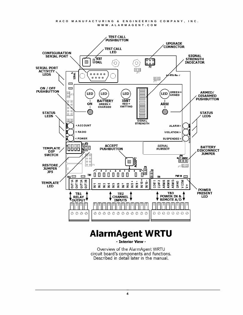
To connect the battery, remove any cover and locate the jumper pins marked BATT DISCNT on the right hand edge of the circuit board near the bottom (refer to diagram). Move the jumper from the right hand position to the left hand position.
Test the battery connection by temporarily turning on the WRTU via the ON/OFF button. The LEDs should flash rapidly, assuming there is no 12 to 24 VDC power connected yet. (When operating on battery in the absence of power input, the LEDs flash to conserve battery capacity.)
Be sure to turn the WRTU off again promptly to prevent the WRTU from attempting to transmit a power failure alarm.
TNote:T When turning the WRTU OFF, there will be a short delay before the LEDs actually turn off. This is normal.
If you ever ship the WRTU to another location, be sure to disconnect the battery by moving this jumper to the right hand position before packaging and shipping.
3.0 Choosing a Location for the WRTU and AntennaThe location you choose for installing your AlarmAgentP
TMP WRTU is important if the antenna is
mounted directly on top of the WRTU. This is because the antenna location has a lot to do with the signal strength of the wireless connection to the local cellular tower.
If the antenna is to be located separately from the WRTU, then the mounting location of the WRTU is not as critical.
To select an optimum location for either the WRTU with top-mounted antenna or for a separately located antenna, use the bar-graph LED signal strength indicator built into the WRTU. To view the signal strength indication, turn on the WRTU.
TNote:T If you are installing the WRTU inside a metal enclosure, it will be necessary to install an antenna at a separate location outside the metal enclosure.
If the WRTU is being installed in a control panel at a location other than the final destination, issues of antenna placement and network testing will need to be dealt with separately at the time of final installation at the ultimate WRTU site.
If input power has not yet been connected, you can still view the bar graph which will flash along with all other LEDs).
The stronger the signal strength is, the more segments that will be illuminated. At least four segments of the bar graph should be lit, allowing for momentary variances. Allow a few seconds
5

R A C O M A N U F A C T U R I N G & E N G I N E E R I N G C O M P A N Y , I N C . W W W . A L A R M A G E N T . C O M
for the indication to adjust to any new antenna positioning.
• See Appendix A for advanced antenna information
4.0 Mounting the WRTU With the mounting location for the WRTU determined, use the enclosed Mounting Template diagram (Appendix G) to establish mounting-hole locations. This diagram includes hole locations for WRTUs with three different enclosure options:
1. Open Chassis
2. Standard Indoor
3. NEMA 4X
5.0 Deto simplify configuration of the WRTU for different monitoring applications, the WRTU incorporates seven different Application Templates. Determine which Application Template that is appropriate for your monitoring application from the listing below:
ermining the correct Application Template
UNote that the choice of Application Template will determine the appropriate wiring connections to be madeU.
1) Duplex pump station with no pulse flowmeter installed
2) Duplex pump station with a pulse flowmeter installed
3) Triplex pump station with no pulse flowmeter installed
4) Triplex pump station with a pulse flowmeter installed
5) Multipurpose Equipment Service: 3 DRT*, 5 digital and 2 universal** Channels
6) Multipurpose Service/Performance: 1 DRT*, 7 digital and 2 universal** Channels
7) Multipurpose Process Performance: 8 digital and 2 universal** Channels
T
6

R A C O M A N U F A C T U R I N G & E N G I N E E R I N G C O M P A N Y , I N C . W W W . A L A R M A G E N T . C O M
T* DRT Channels may be configured as Discrete, Runtime, or Totalizing Channels
** Universal Channels 9 and 10 may be configured as either digital or analog Channels
6.0 Power and Ground Wiring Connections
Referring to the connection diagram, connect a source of 12 to 24 VDC power to the input terminals indicated on the diagram. The power source should be capable of delivering12 VDC @ 200 ma or 24 VDC @ 100 ma.
Note: The terminal strips have particularly small screw heads. For your convenience, a suitable screwdriver is provided with the WRTU, held by a clip at the bottom end of the metal chassis.
Note that RACO offers a suitable 12 VDC outlet adapter as an accessory item.
Be sure to connect the terminal marked GRND to a good electrical ground. This is important for maximum electrical surge protection.
Also Note: The terminal strips are unpluggable. They accommodate #26 to #16 AWG wire size.
7.0 Signal Wiring Connections Refer to the signal wiring diagrams in Appendix D which are included independently for each specific Application Template. Note: Be sure that the
digital inputs are non-powered (dry) contacts; otherwise the WRTU may be damaged.
For optional analog input wiring connections, as well as connections for relay outputs and optional remote Arm/Disarm module, refer to Appendix E.
8.0 Preliminary Local Configuration of the WRTU Virtually all configuration operations can be done remotely from the web site (http://HTUwww.alarmagent.comUTH).
UHowever, there are two simple configuration steps which we strongly suggest doing at the WRTU.
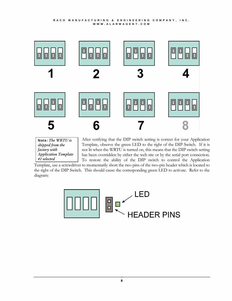
Step 1: Set the Application Template After determining the correct Application Template from the above information, locate the four-position DIP switch on the left hand edge of the circuit board. Refer to the diagram. With the WRTU turned on, set the Application Template according to the following diagram:
7
R A C O M A N U F A C T U R I N G & E N G I N E E R I N G C O M P A N Y , I N C . W W W . A L A R M A G E N T . C O M
After verifying that the DIP switch setting is correct for your Application Template, observe the green LED to the right of the DIP Switch. If it is not lit when the WRTU is turned on, this means that the DIP switch setting has been overridden by either the web site or by the serial port connection. To restore the ability of the DIP switch to control the Application
Template, use a screwdriver to momentarily short the two pins of the two-pin header which is located to the right of the DIP Switch. This should cause the corresponding green LED to activate. Refer to the diagram:
Note: The WRTU is shipped from the factory with Application Template #1 selected
8

R A C O M A N U F A C T U R I N G & E N G I N E E R I N G C O M P A N Y , I N C . W W W . A L A R M A G E N T . C O M
Also note that if you do change the template from the default of template 1, it may cause the WRTU to send the change to the web site, as indicated by a temporary change in color of the System Activity (Transmit) LED.
Note: As with other configuration items, the Application Template can be set via the DIP Switch, via the serial port, or via the web site. The LED indicates that the Application Template setting presently agrees with the DIP switch setting. If the Application Template is subsequently changed via the serial port or via the web site, the LED will turn OFF.
Step 2: Set the Normally Open / Normally Closed Alarm Criteria for All Digital Inputs Place all alarmable digital inputs in their normal, non-alarm condition.
Then, with the WRTU turned on, momentarily press the ACCEPT pushbutton which is located in the lower center area of the circuit board (Refer to diagram).
This automatically configures the alarm condition for each alarmable input to the opposite of the current open/closed condition.
9.0 Optional Advanced Configuration of the WRTU For most users, the above two steps will complete most of the configuration needed at the RTU.
However, in some cases you may wish to perform advanced configuration settings by using the serial port connection to a local portable computer.
For those using analog inputs, in most cases the scaling and set points can be handled at the web site. The exception is that if you need to establish set points to a detailed resolution greater than 2% of full scale, you will need to establish the set point via the serial port connection rather than via the web site.
If you wish to perform optional advanced configuration using the VT-100 serial interface, refer to Appendix B (for configuring Hyperterminal on your computer) and Appendix C (for added info on using the VT-100 menu-driven interface).
10.0 Interpreting LED indications BAR GRAPH: The number of segments (out of 10 segments total) that are lit indicates the relative signal strength of the wireless link to the local cellular tower.
9

R A C O M A N U F A C T U R I N G & E N G I N E E R I N G C O M P A N Y , I N C . W W W . A L A R M A G E N T . C O M
LARGE LEDS:
RED GREEN AMBER OFF
ON/OFF WRTU ON WRTU OFF BATTERY DISCHARGING FULLY CHARGED CHARGING
SYSTEM ACTIVITY
INDICATOR PROBLEM NORMAL TRANSMISSION
PENDING NO SERVICE AVAILABLE
ARM/DISARM DISARMED (FLASHING) ARMED ACCOUNT IS
DISABLED
SMALL LEDS:
LOCATION COLOR INDICATES
ACCOUNT LEFT OF LEGEND PLATE GREEN THIS WRTU’S ACCOUNT IS ACTIVATED
RADIO LEFT OF LEGEND PLATE GREEN FLASHING INDICATES NORMAL (HEARTBEAT)
POWER INPUT LEFT OF LEGEND PLATE YELLOW EXTERNAL POWER PRESENT
ALARM RIGHT OF LEGEND PLATE RED SOME CHANNEL OR CONDITION IS IN ALARM
VIOLATION RIGHT OF LEGEND PLATE YELLOW SOME CHANNEL OR CONDITION HAS PRELIMINARY ALARM VIOLATION
SUSPENDED RIGHT OF LEGEND PLATE RED SOME CHANNEL IS TEMPORARILY DISABLED FROM SENDING ALARM
INPUT CONDITION ABOVE EACH INPUT RED INPUT IS CLOSED CIRCUIT POWER INPUT BOTTOM RIGHT YELLOW EXTERNAL POWER PRESENT
TEMPLATE RIGHT OF DIP SWITCH GREEN APPLICATION TEMPLATE # AGREES WITH DIP SWITCH SETTING
OUTPUT RELAY #1 ABOVE 4 POINT TS RED RELAY # 1 IS ACTIVATED OUTPUT RELAY #2 ABOVE 4 POINT TS RED RELAY #2 IS ACTIVATED
SERIAL PORT LED D26 LEFT EDGE BELOW SERIAL
PORT RED/GREEN GREEN: SERIAL PORT CONNECTION
SERIAL PORT LED D27 LEFT EDGE BELOW SERIAL
PORT RED/GREEN GREEN: SERIAL PORT CONNECTION
TEST CALL LED D25 RIGHT OF TEST CALL
PUSHBUTTON GREEN TEST CALLS ARE ENABLED
Note
The digital inputs each have their own LED indicator directly above their respective connection points. Each LED activates when the corresponding digital input is in the CLOSED condition.
10

R A C O M A N U F A C T U R I N G & E N G I N E E R I N G C O M P A N Y , I N C . W W W . A L A R M A G E N T . C O M
UThis allows checking of signal input wiring even at a pre-installation site.U
First, put the WRTU in the Disarmed state as described below. Then you can manipulate the input signal sources to verify that when those input signal sources are closed, the corresponding LED on the circuit board is activated.
11.0 Armed and Disarmed States Normally the WRTU should be left in the Armed state (LED shows Green) so that it can send transmissions to the web site when alarm conditions occur.
If you wish to prevent alarm transmissions temporarily, place the WRTU in Disarmed state (LED flashes Red). This should be done for example when you are performing maintenance at the RTU site and wish to prevent false alarms.
While in the Disarmed state, scheduled report transmissions will still be sent.
Be sure to check the Armed/Disarmed state before leaving the site.
12.0 Verifying the Wireless Network Link to the Web Site Before this can be done, the WRTU’s service must have been activated, and the WRTU must have been imported into your system at the web site.
13.0 UsinTo use the Tpushbutton (re
The Test Callspecial Test Ca
With the Test site, momenta
Within a minutest call will inc
Your company’s Customer System Administrator (CSA)can advise you as to whether this has been done.
g the Test Call Feature for Network Verification est Call Feature, first verify that the green LED located to the right of the Test Call fer to diagram) is lit. If not, the Test Call feature will not work until re-enabled by RACO.
LED is normally lit, but it will be turned off if someone presses the button without a ll Notification Phone Number having been previously entered at the web site by a CSA.
Call LED lit, and after verifying that your cell phone number has been entered at the web rily press the Test Call pushbutton.
te or so, you should receive a corresponding notification test call to your cell phone. The lude the signal strength of the signal received by the local tower.
11

R A C O M A N U F A C T U R I N G & E N G I N E E R I N G C O M P A N Y , I N C . W W W . A L A R M A G E N T . C O M
Note that the cellular network requires at least a two minute interval between transmissions from the WRTU. Therefore if you were to press the Test Call pushbutton more than once within a two minute span, (this should not be necessary), the second transmission will be delayed.
14.0 Testing by Simulating Alarm Conditions: Testing by artificially creating alarm conditions introduces complications having to do with various timing delays, as well as the fact that the WRTU filters out “dithering” alarm inputs. Therefore this method is not recommended unless you trip any given alarm only once, and allow more than two minutes between tripping different alarms.
Note that the power failure alarm, depending upon the configuration, will take longer to trip (5 minutes is the default setting) than other input alarms.
As described above, the red LEDs associated with each digital input can provide confirmation that the wiring to various signal sources is correct. This should generally be done while the WRTU is in the Disarmed state in order to prevent unnecessary alarm transmissions.
12

R A C O M A N U F A C T U R I N G & E N G I N E E R I N G C O M P A N Y , I N C . W W W . A L A R M A G E N T . C O M
Appendix A: Advanced Antenna Topics Antenna options for your AlarmAgentP
TMP WRTU depend in part upon whether or not the WRTU
is installed within a metallic cabinet or metal building.
If the WRTU is installed within a metal cabinet or metal building:
If the WRTU is installed within a metal cabinet, the antenna will need to be located separately outside the enclosure. This in turn will require a “cabinet cable” which runs from the WRTU to somewhere on the outer surface of the cabinet. Cabinet cables are available in 18” and 36” lengths, or other lengths on special order. The same is true if the WRTU is installed inside a metal building, except that a longer extension cable will be required in lieu of the cabinet cable, to reach a suitable outer surface of the building. Extension cables are available in 12’ and 30’ lengths, or other lengths on special order.
Note
If your cell phone works outside the building but not inside the building at the WRTU location, you can assume that a separately located external antenna will be required.
There are two primary choices for separately located antennas:
1. A PhantomP
®P antenna. The advantages of this antenna include simple installation and a low
profile design that is highly resistant to vandalism.
2. A Yagi directional antenna. The advantage of a Yagi antenna is its particularly high gain and directionality. This can be important in areas where there is weak cellular tower coverage.
RACO has suitable Yagi antennas available as accessory items for AlarmAgent.
If the WRTU is installed indoors, but not inside a metal cabinet or metal building:
If the WRTU is installed indoors, but not inside a metal cabinet or metal building, which standard antenna to use depends upon the WRTU’s enclosure option.
1. A “rubber duck” antenna is standard for the Indoor Enclosure or Open Chassis option.
2. A PhantomP
®P antenna is standard for the outdoor NEMA 4X enclosure option.
13

R A C O M A N U F A C T U R I N G & E N G I N E E R I N G C O M P A N Y , I N C . W W W . A L A R M A G E N T . C O M
Regardless of the enclosure option, in some cases it is necessary to install a Yagi (directional) antenna in order to obtain adequate communication with the nearest AMPS cellular tower.
A special caution about using cell phones to assess signal strength…
While any cell phone can be used to assess whether a separately located “outside the building” antenna is required as described above, a cell phone cannot be relied upon to assess the need for a high-gain antenna. This is because the AlarmAgentP
TM
PWRTU uses the AMPS cellular network, while some cell phones use different networks with different tower locations. The LED bar graph on the AlarmAgentP
TM
PWRTU is the proper reference for signal strength. In general, if the bar graph shows less than three bars illuminated with a non-directional antenna, you may need a Yagi directional antenna.
14

R A C O M A N U F A C T U R I N G & E N G I N E E R I N G C O M P A N Y , I N C . W W W . A L A R M A G E N T . C O M
Appendix B: Configuring HyperTerminal HyperTerminal is a Windows accessory that enables you to connect your computer to your
AlarmAgentP
TMP WRTU.
Note that this configuration setup can be done on your portable computer in advance prior to visiting the RTU site. When you installed Windows, you were given the option to install HyperTerminal as one of your accessories. If you did not install HyperTerminal or you removed it from the Start menu, you can install it at any time by selecting Install/Remove Applications.
Creating a Connection (Windows XP) To run HyperTerminal, click the Start button and choose Programs, Accessories, HyperTerminal. When the “Connection Description” dialog appears, enter a descriptive name and select an icon to represent the connection for future use. Click OK actions from Control Panel. To run HyperTerminal, click the Start button and choose Programs, Accessories, HyperTerminal.
When the “Connect To” dialog appears, select the communications port that is connected to your AlarmAgentP
TMP WRTU. Click OK.
Note: If you have not yet configured your modem, Windows will prompt you to set it up. You can ignore this because no modem is required for the serial port connection.
15

R A C O M A N U F A C T U R I N G & E N G I N E E R I N G C O M P A N Y , I N C . W W W . A L A R M A G E N T . C O M
The communications port properties dialog will appear. You need to set the “Bits per Second” to 57600 and Flow control to “None.” Click OK.
The HyperTerminal window will appear. From the “File” menu, select “Properties.” Click on the “Settings: tab. Change the Emulation to “VT100.” Click OK.
Creating a Connection (Windows 98) Follow the directions for creating a connection for Windows XP, except to run HyperTerminal in Win98, click the Start button and choose Programs, Accessories, HyperTerminal. When the HyperTerminal folder appears, click on the Hypertrm.exe icon.
16

R A C O M A N U F A C T U R I N G & E N G I N E E R I N G C O M P A N Y , I N C . W W W . A L A R M A G E N T . C O M
Appendix C: Optional Advanced Configuration using the serial VT100 interface To perform advanced configuration using the serial port, plug one end of a 9-PIN Female-to-Female
“PC to PC Transfer Cable” (also called “Laplink” or “crossover” serial cable), into the 9-pin serial port located in the upper left area of the circuit board. Refer to the diagram.
Note: RACO has this cable available as an accessory item.
Plug the other end of the cable into your computer. Activate HyperTerminal and select the Connection you have created as described in Appendix B. With the connection session established, press Enter to get the top Welcome menu.
Note: an USB/serial port adapter will be required if your computer does not have a serial port. As part of this, it will be necessary for you to determine which COM Port the USB interface is on.
The WRTU incorporates a user-friendly, menu driven VT100 user interface, under which a variety of special settings may be selected.
Note: the session will time outand any unsaved entries will belost, if there is no activity for a period of ten minutes. Entries will be lost if you fail to click onthe Save buttons.
17

R A C O M A N U F A C T U R I N G & E N G I N E E R I N G C O M P A N Y , I N C . W W W . A L A R M A G E N T . C O M
Appendix D: Signal Input wiring for each Application Template
NOTES: Dry (non-powered) contact inputs only!
Pump 1 Input: Closed when Pump 1 runs.
Pump 2 Input: Closed when pump 2 runs.
High (or low) level alarm can be either Normally Closed or Normally Open.
To use Channels 9 or 10 as analog inputs, see separate diagram.
Ground connection is important for surge protection.
Terminals accommodate #16 to #26 wire size.
WIRING INSTRUCTIONS FOR TEMPLATE 1:
18

R A C O M A N U F A C T U R I N G & E N G I N E E R I N G C O M P A N Y , I N C . W W W . A L A R M A G E N T . C O M
1) Turn WRTU on, and Disarm it (so that the right hand Arm/Disarm LED blinks).
2) Designate (identify) a Pump 1 and Pump 2 for the purposes of AlarmAgent monitoring.
3) Verify that all contact inputs are dry (un-powered). Otherwise, WRTU will be damaged.
4) Connect contact inputs for Pump 1, Pump 2 and a high (or low) level float switch or other
signal source
5) Connect any other desired inputs to channels 4 through 10 See separate instructions and diagram for using Channels 9 and 10 as analog inputs.
6) Place any contact inputs to Channels 4 through 10 in their normal, non-alarm state. Press
the ACCEPT BUTTON. This automatically configures Channels 4 through 10 to alarm on the opposite input state.
7) TEST WIRING! Verify the following:
a) Channel 1 LED activates when Pump 1 runs.
b) Channel 2 LED activates when Pump 2 runs.
c) When High (or Low) alarm switch is tripped, Channel 3 LED responds accordingly.
It should activate whenever the switch is closed. Test wiring for any remaining inputs by manipulating their state and verifying that the corresponding Channel LED activates when the input is closed (and deactivates when the input is open).
19

R A C O M A N U F A C T U R I N G & E N G I N E E R I N G C O M P A N Y , I N C . W W W . A L A R M A G E N T . C O M
NOTES: Dry (non-powered) contact inputs only!
Pump 1 Input: Closed when Pump 1 runs.
Pump 2 Input: Closed when pump 2 runs.
Totalizer pulses must be at least 50 milliseconds (.05 seconds) duration, 10 pulses per
second maximum To use Channels 9 or 10 as analog inputs, see separate diagram.
Ground connection is important for surge protection.
Terminals accommodate #16 to #26 wire size.
20
R A C O M A N U F A C T U R I N G & E N G I N E E R I N G C O M P A N Y , I N C . W W W . A L A R M A G E N T . C O M
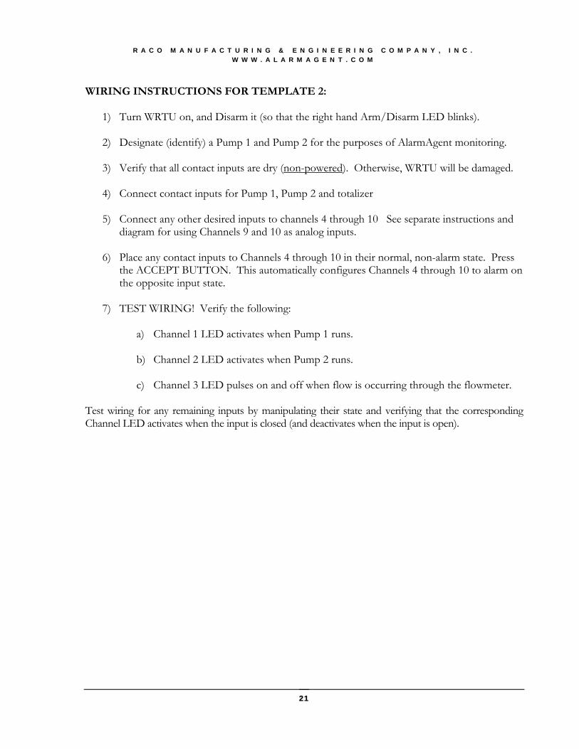
WIRING INSTRUCTIONS FOR TEMPLATE 2:
1) Turn WRTU on, and Disarm it (so that the right hand Arm/Disarm LED blinks).
2) Designate (identify) a Pump 1 and Pump 2 for the purposes of AlarmAgent monitoring.
3) Verify that all contact inputs are dry (non-powered). Otherwise, WRTU will be damaged.
4) Connect contact inputs for Pump 1, Pump 2 and totalizer
5) Connect any other desired inputs to channels 4 through 10 See separate instructions and diagram for using Channels 9 and 10 as analog inputs.
6) Place any contact inputs to Channels 4 through 10 in their normal, non-alarm state. Press
the ACCEPT BUTTON. This automatically configures Channels 4 through 10 to alarm on the opposite input state.
7) TEST WIRING! Verify the following:
a) Channel 1 LED activates when Pump 1 runs.
b) Channel 2 LED activates when Pump 2 runs.
c) Channel 3 LED pulses on and off when flow is occurring through the flowmeter.
Test wiring for any remaining inputs by manipulating their state and verifying that the corresponding Channel LED activates when the input is closed (and deactivates when the input is open).
21
R A C O M A N U F A C T U R I N G & E N G I N E E R I N G C O M P A N Y , I N C . W W W . A L A R M A G E N T . C O M
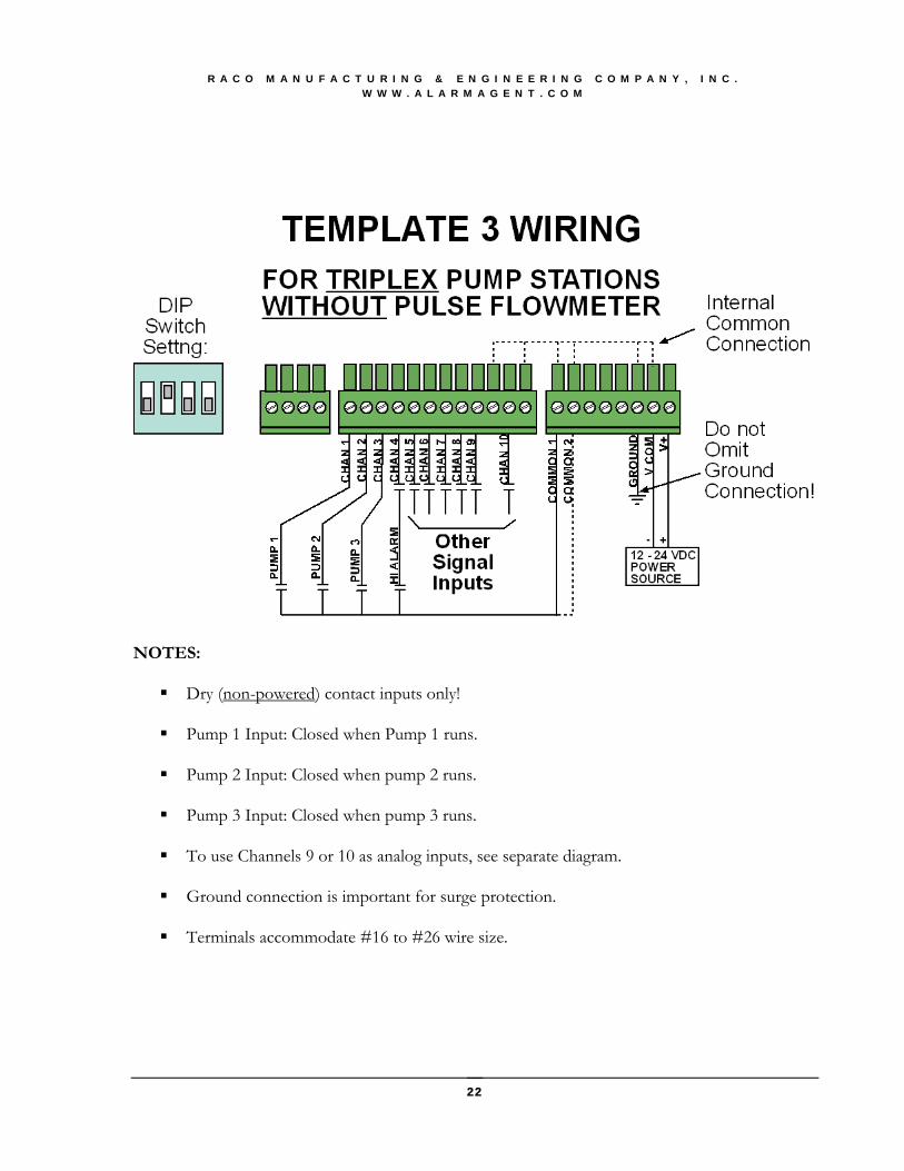
NOTES: Dry (non-powered) contact inputs only!
Pump 1 Input: Closed when Pump 1 runs.
Pump 2 Input: Closed when pump 2 runs.
Pump 3 Input: Closed when pump 3 runs.
To use Channels 9 or 10 as analog inputs, see separate diagram.
Ground connection is important for surge protection.
Terminals accommodate #16 to #26 wire size.
22
R A C O M A N U F A C T U R I N G & E N G I N E E R I N G C O M P A N Y , I N C . W W W . A L A R M A G E N T . C O M
WIRING INSTRUCTIONS FOR TEMPLATE 3:
1) Turn WRTU on, and Disarm it (so that the right hand Arm/Disarm LED blinks).
2) Designate (identify) a Pump 1, Pump 2 and Pump 3 for the purposes of AlarmAgent monitoring.
3) Verify that all contact inputs are dry (non-powered). Otherwise, WRTU will be damaged.
4) Connect contact inputs for Pump 1, Pump 2 and Pump 3.
5) Connect any other desired inputs to channels 4 through 10 See separate instructions and
diagram for using Channels 9 and 10 as analog inputs.
6) Place any contact inputs to Channels 4 through 10 in their normal, non-alarm state. Press the ACCEPT pushbutton. This automatically configures Channels 4 through 10 to alarm on the opposite input state.
7) TEST WIRING! Verify the following:
a) Channel 1 LED activates when Pump 1 runs.
b) Channel 2 LED activates when Pump 2 runs.
c) Channel 3 LED activates when Pump 3 runs.
Test wiring for any remaining inputs by manipulating their state and verifying that the corresponding Channel LED activates when the input is closed (and deactivates when the input is open).
23

R A C O M A N U F A C T U R I N G & E N G I N E E R I N G C O M P A N Y , I N C . W W W . A L A R M A G E N T . C O M
NOTES: Dry (non-powered) contact inputs only!
Pump 1 Input: Closed when Pump 1 runs.
Pump 2 Input: Closed when pump 2 runs.
Pump 3 Input: Closed when pump 3 runs.
Channel 4: Digital Pulse Flowmeter input must have minimum closure duration of 50
milliseconds and pulse rate less than 10 pulses per second. 5 volt logic outputs can be used. To use Channels 9 or 10 as analog inputs, see separate diagram.
Ground connection is important for surge protection.
Terminals accommodate #16 to #26 wire size.
24

R A C O M A N U F A C T U R I N G & E N G I N E E R I N G C O M P A N Y , I N C . W W W . A L A R M A G E N T . C O M
WIRING INSTRUCTIONS FOR TEMPLATE 4:
1) Turn WRTU on, and Disarm it (so that the right hand Arm/Disarm LED blinks).
2) Designate (identify) a Pump 1, Pump 2 and Pump 3 for the purposes of AlarmAgent monitoring.
3) Verify that all contact inputs are dry (non-powered). Otherwise, WRTU will be damaged.
4) Connect contact inputs for Pump 1, Pump 2 and Pump 3.
5) Connect digital pulse flowmeter input to Channel 4.
6) Connect any other desired inputs to channels 5 through 10 See separate instructions and
diagram for using Channels 9 and 10 as analog inputs.
7) Place any contact inputs to Channels 5 through 10 in their normal, non-alarm state. Press the ACCEPT pushbutton. This automatically configures Channels 4 through 10 to alarm on the opposite input state.
8) TEST WIRING! Verify the following:
a) Channel 1 LED activates when Pump 1 runs.
b) Channel 2 LED activates when Pump 2 runs.
c) Channel 3 LED activates when Pump 3 runs.
d) Channel 4 LED pulses when flow through flowmeter is occurring
Test wiring for any remaining inputs by manipulating their state and verifying that the corresponding Channel LED activates when the input is closed (and deactivates when the input is open).
25

R A C O M A N U F A C T U R I N G & E N G I N E E R I N G C O M P A N Y , I N C . W W W . A L A R M A G E N T . C O M
NOTES: Dry (non-powered) contact inputs only!
Channels 1, 2 and 3 may be independently configured for pulse totalizing, run time
accumulation or simple digital inputs, using advanced configuration via the serial port or via the web site.
To use Channels 9 or 10 as analog inputs, see separate diagram.
Ground connection is important for surge protection.
Terminals accommodate #16 to #26 wire size.
WIRING INSTRUCTIONS FOR TEMPLATE 5:
1) Turn WRTU on, and Disarm it (so that the right hand Arm/Disarm LED blinks).
2) Connect input wiring as needed per the above diagram.
3) Place all inputs in their normal, non-alarm state. Press the ACCEPT pushbutton. This automatically configures inputs to alarm on the opposite input state.
4) If any inputs (such as run time or totalizer inputs) are to be non-alarming, after using the
Accept pushbutton, configure those inputs as Status Only via the serial port or via the web site.
26
R A C O M A N U F A C T U R I N G & E N G I N E E R I N G C O M P A N Y , I N C . W W W . A L A R M A G E N T . C O M
5) TEST WIRING! Test input wiring by manipulating the state of inputs and verifying that
the corresponding Channel LED activates when the input is closed (and deactivates when the input is open).
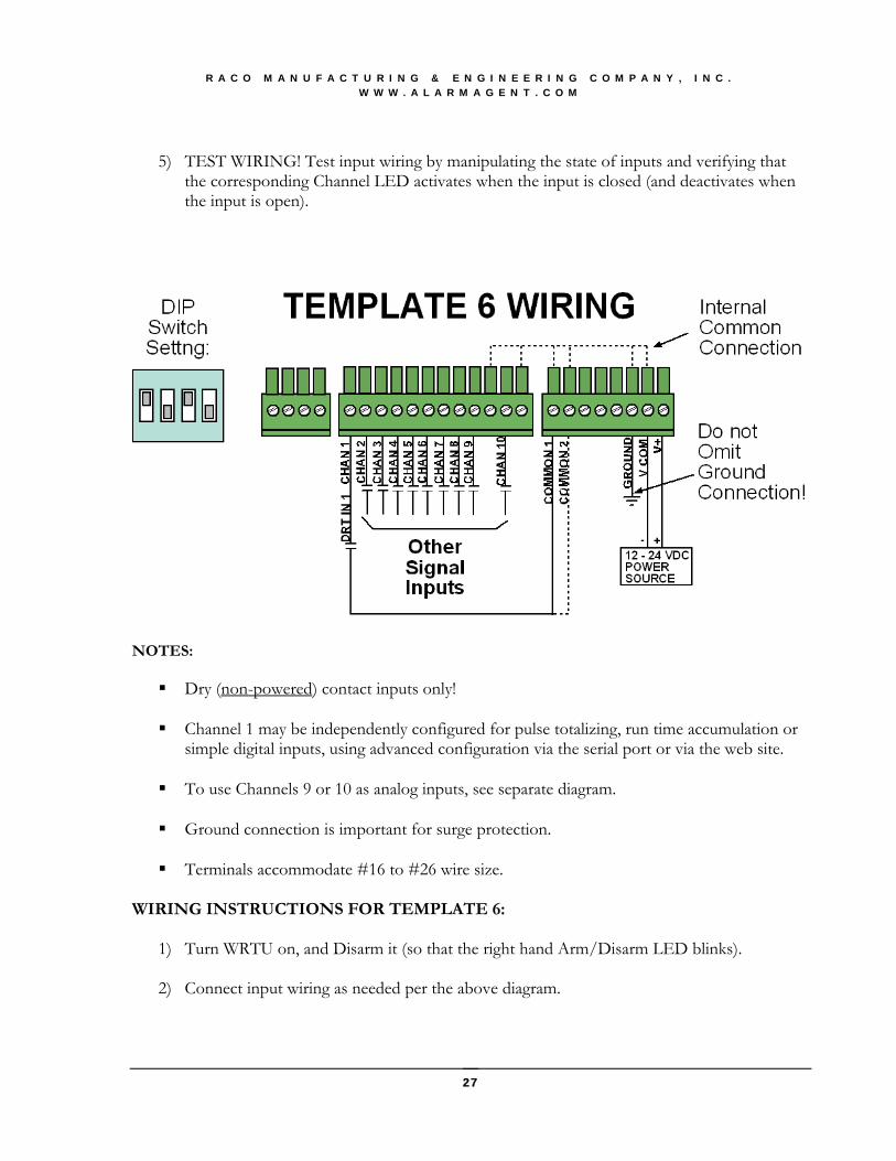
NOTES: Dry (non-powered) contact inputs only!
Channel 1 may be independently configured for pulse totalizing, run time accumulation or
simple digital inputs, using advanced configuration via the serial port or via the web site. To use Channels 9 or 10 as analog inputs, see separate diagram.
Ground connection is important for surge protection.
Terminals accommodate #16 to #26 wire size.
WIRING INSTRUCTIONS FOR TEMPLATE 6:
1) Turn WRTU on, and Disarm it (so that the right hand Arm/Disarm LED blinks).
2) Connect input wiring as needed per the above diagram.
27

R A C O M A N U F A C T U R I N G & E N G I N E E R I N G C O M P A N Y , I N C . W W W . A L A R M A G E N T . C O M
3) Place all inputs in their normal, non-alarm state. Press the ACCEPT pushbutton. This automatically configures inputs to alarm on the opposite input state.
4) If any inputs (such as run time or totalizer input on channel 1) are to be non-alarming, after
using the Accept pushbutton, configure those inputs as Status Only via the serial port or via the web site.
5) TEST WIRING! Test input wiring by manipulating the state of inputs and verifying that
the corresponding Channel LED activates when the input is closed (and deactivates when the input is open).
NOTES: Dry (non-powered) contact inputs only!
To use Channels 9 or 10 as analog inputs, see separate diagram.
Ground connection is important for surge protection.
Terminals accommodate #16 to #26 wire size.
WIRING INSTRUCTIONS:
1) Turn WRTU on, and Disarm it (so that the right hand Arm/Disarm LED blinks).
2) Connect input wiring as needed per the above diagram.
3) Place all inputs in their normal, non-alarm state. Press the ACCEPT pushbutton. This automatically configures inputs to alarm on the opposite input state.
28

R A C O M A N U F A C T U R I N G & E N G I N E E R I N G C O M P A N Y , I N C . W W W . A L A R M A G E N T . C O M
4) If any inputs are to be non-alarming, after using the Accept pushbutton, configure those
inputs as Status-Only via the serial port or via the web site.
5) TEST WIRING! Test input wiring by manipulating the state of inputs and verifying that the corresponding Channel LED activates when the input is closed (and deactivates when the input is open).
29

R A C O M A N U F A C T U R I N G & E N G I N E E R I N G C O M P A N Y , I N C . W W W . A L A R M A G E N T . C O M
Appendix E: AlarmAgentP
TMP Analog Input, Relay Output and
Remote Arm/Disarm Module Wiring Connections
30

R A C O M A N U F A C T U R I N G & E N G I N E E R I N G C O M P A N Y , I N C . W W W . A L A R M A G E N T . C O M
Appendix F: AlarmAgentP
TMP WRTU Specification
MODELS AlarmAgent.com Wireless Remote Terminal Units (WRTU) are offered in 4 different models: AA-102 AlarmAgent.com WRTU with NEMA 1 Enclosure AA-102OC AlarmAgent.com WRTU with Open Chassis AA-102NEMA4XP AlarmAgent.com WRTU with NEMA 4X Enclosure and Phantom Antenna AA-102NEMA4XY AlarmAgent.com WRTU with NEMA 4X Enclosure and Yagi Directional Antenna ELECTRICAL Eight Digital Inputs: For connection to dry (unpowered) contacts. Open circuit voltage 5VDC; closed circuit current 2mA DC. Pulse Totalizing: Minimum closed pulse width 50 millisaconds; maximum pulse rate 10 pps. Two Universal Signal Inputs: Digital: Open circuit voltage 5VDC; closed circuit current 2mA DC. Analog: 4-20MA, single ended. Maximum voltage drop 2.5 VDC. Resolution: 0.1%, absolute accuracy is 0.25%. Two Relay Outputs: Normally Open Relays, 0.5-ampere @ 120VAC Serial Port: 9 pin D Sub male RS232 configuration port Battery Backup: 24 hours, 12 volt @ 1.2 Amp Hr Power Management: System intelligently manages power during power failure. Power Requirements: User supplied. The WRTU operates on 12 to 24 VDC power input. With 12 VDC input, current is 1-ampere peak, 200 mA average. With 24 VDC input, current is 0.5-ampere peak, 100 mA average. Battery Charging: Precision voltage controlled to maximize battery life and rapidly recharge the battery after power failure. Power Failure: Automatic alarm for external power failure and low battery detection. Power Consumption: 2 watts nominal Solar Power: In solar power mode, average current is 60 ma @ 12 VDC (0.72 watts) Surge Protection: Digital inputs are opto-isolated and rated at 5,000 volts. Universal inputs are rated at 600 watts. Power input is protected to 1,500 watts peak. The fuse is automatically reset. PHYSICAL Enclosure: Open chassis: 9.6" H x 4.0" W x 2.44" D NEMA 1 enclosure: 9.6" H x 4.35" W x 2.75" D NEMA 4X enclosure: 11.5" H x 4.33" W x 5.5" D Mounting Centers: Open chassis: 3-1/2" x 5-15/16" NEMA 1 enclosure: 3-1/2" x 6-19/32" NEMA 4X enclosure: 4" x 8-3/4" Weight:
Open chassis: 2.4 lbs w/rubber duck antenna NEMA 1 enclosure: 2.7 lbs w/rubber duck antenna NEMA 4X enclosure: 5.5 lbs w/Phantom antenna ENVIRONMENTAL Temperature range: Operating, -30 to + 70°C (-22 to +158°F) Storage, -40 to + 85°C (-40 to +185°F) Humidity: 0 to 95% non-condensing COMMUNICATIONS Bi-directional WRTU communications are handled by the AlarmAgent.com secure server via the wireless cellular network. SYSTEM CONFIGURATION The WRTU is configurable via any of three possible means: via dipswitch, via notebook computer connected to the serial port, or wirelessly via AlarmAgent.com. In most cases, a notebook computer connection is not required. By selecting from 4 templates that are optimized for duplex pump stations with or without totalizer and triplex pump stations with or without totalizer, rapid installation and error proof startup are virtually guaranteed. Three additional templates are available for more general applications. ALARM AND SYSTEM MESSAGES User defined alarm and system messages are delivered via voice calls, SMS messages, alphanumeric pagers, and e-mail to an unlimited number of user specified destinations. Authorized personnel acknowledge alarms during voice calls via a toll free number, e-mail, or through the AlarmAgent.com Web site. OPERATOR INTERFACE The AlarmAgent.com WRTU includes pushbuttons to turn the unit on or off, to arm or disarm the unit, to cause a special Test Call to be generated, and a digital input Accept function to assist in the setup of the WRTU. LEDs are used extensively throughout to indicate the status of the following subsystems: AC power status, battery status, network service availability, a 10 segment LED bar graph for service signal strength, actively transmitting, test report, customer account status, template setting status, individual input channel state, individual relay output state, and if any channels have exceeded their daily limit of transmissions. WARRANTY Three year parts and labor warranty, FOB factory Emeryville, CA FIELD UPGRADES AlarmAgent.com WRTU firmware is field upgradeable.
31

R A C O M A N U F A C T U R I N G & E N G I N E E R I N G C O M P A N Y , I N C . W W W . A L A R M A G E N T . C O M
Appendix G: AlarmAgentP
TMP WRTU Mounting Templates
This page intended to be blank so the following mounting template can
be removed from the manual as required.
32

/4”)
A A
B B
CC
C C
B B
A A
VERIFY 0”4.
IS 4.0”!GRAM
SPIS
AD
NIA
TB EF ORE
HAT THUSING
ISTH
PL
OPEN C HASSIS MOUNT: 4 HOLES MARKED “C ”,
(1US
1/64” F T WO OR
REA#8R
SC
CRLEA
ER
WA
S ORNCE
9/64” FHOLES
ORMA
SR
ELF KED T
“ AP
, D”)1(
)(;P
I5
N
/D O 32”
OR EF OR
N # C 6
LOSC
SR
UREEW
: 4 HO/S OR 7LE64
S”
MF
AO
RR
KED
SEL “B
F T
”A
;A”“MM
AA
RKEX D
D 4X4
”
EX
N C8.
LO75”
SC
UREN
ET
: 4ER
HS;
O5
L/
ES”16
A NEM
DD
”.542”211.

R A C O M A N U F A C T U R I N G & E N G I N E E R I N G C O M P A N Y , I N C . W W W . A L A R M A G E N T . C O M
34

R A C O M A N U F A C T U R I N G & E N G I N E E R I N G C O M P A N Y , I N C . W W W . A L A R M A G E N T . C O M
35
INDEX ACCEPT pushbutton ........................... 9, 23, 25, 26, 28 Advanced Configuration........................................ 9, 17 alarm conditions .................................................. 11, 12 analog input ................................................................. 7 antenna................................................... 5, 6, 13, 14, 31 Application Template .......................... 6, 7, 8, 9, 10, 18 Armed.................................................................. 10, 11 bar graph.......................................................... 5, 14, 31 battery.................................................................... 5, 31 cabinet cable .............................................................. 13 CSA ....................................................................... 2, 11 DIP switch ..................................................... 7, 8, 9, 10 Disarmed........................................................ 10, 11, 12 Hyperterminal.............................................................. 9 Installers ..................................................................... 2
LED indications .......................................................... 9 Local Configuration .................................................... 7 location...............................................................5, 6, 13 Mounting..........................................................6, 31, 32 power failure alarm ............................................... 5, 12 serial VT100 interface............................................... 17 set points ..................................................................... 9 signal strength ..............................................5, 9, 11, 14 Specifications ............................................................ 31 Test Call ...............................................2, 10, 11, 12, 31 Test Call Notification Phone Number ................... 2, 11 User ........................................................................... 31 Wireless Network...................................................... 11 wiring ..... 6, 7, 11, 12, 18, 19, 21, 23, 25, 26, 27, 28, 29 yagi antenna .............................................................. 13