manual industrial controls - siemens · collection of the following five simocode pro manuals, is...
TRANSCRIPT

Manual
SIMOCODE pro Fail-Safe Digital Modules
Motor Management and Control Devices
Edition
Industrial Controls
siemens.com11/2017


___________________
___________________
___________________
___________________
___________________
___________________
___________________
___________________
___________________
___________________
___________________
SIMOCODE pro
SIMOCODE pro - Fail-Safe Digital Modules
Manual
11/2017 NEB631679702000/RS-AA/002
Introduction 1
Safety notes 2
SIMOCODE pro Safety 3
Mounting and connection 4
Operation 5
Planning/Configuring 6
Service and maintenance 7
External circuitry 8
Typical circuit diagrams 9
Technical data 10
List of abbreviations A
Siemens AG Division Digital Factory Postfach 48 48 90026 NÜRNBERG GERMANY
3ZX1012-0UF73-0AC0 Ⓟ 11/2017 Subject to change
Copyright © Siemens AG 2011. All rights reserved
Legal information Warning notice system
This manual contains notices you have to observe in order to ensure your personal safety, as well as to prevent damage to property. The notices referring to your personal safety are highlighted in the manual by a safety alert symbol, notices referring only to property damage have no safety alert symbol. These notices shown below are graded according to the degree of danger.
DANGER indicates that death or severe personal injury will result if proper precautions are not taken.
WARNING indicates that death or severe personal injury may result if proper precautions are not taken.
CAUTION indicates that minor personal injury can result if proper precautions are not taken.
NOTICE indicates that property damage can result if proper precautions are not taken.
If more than one degree of danger is present, the warning notice representing the highest degree of danger will be used. A notice warning of injury to persons with a safety alert symbol may also include a warning relating to property damage.
Qualified Personnel The product/system described in this documentation may be operated only by personnel qualified for the specific task in accordance with the relevant documentation, in particular its warning notices and safety instructions. Qualified personnel are those who, based on their training and experience, are capable of identifying risks and avoiding potential hazards when working with these products/systems.
Proper use of Siemens products Note the following:
WARNING Siemens products may only be used for the applications described in the catalog and in the relevant technical documentation. If products and components from other manufacturers are used, these must be recommended or approved by Siemens. Proper transport, storage, installation, assembly, commissioning, operation and maintenance are required to ensure that the products operate safely and without any problems. The permissible ambient conditions must be complied with. The information in the relevant documentation must be observed.
Trademarks All names identified by ® are registered trademarks of Siemens AG. The remaining trademarks in this publication may be trademarks whose use by third parties for their own purposes could violate the rights of the owner.
Disclaimer of Liability We have reviewed the contents of this publication to ensure consistency with the hardware and software described. Since variance cannot be precluded entirely, we cannot guarantee full consistency. However, the information in this publication is reviewed regularly and any necessary corrections are included in subsequent editions.

SIMOCODE pro - Fail-Safe Digital Modules Manual, 11/2017, NEB631679702000/RS-AA/002 5
Table of contents
1 Introduction ............................................................................................................................................. 9
1.1 Important information ................................................................................................................ 9
1.2 Security information ................................................................................................................ 12
1.3 Current information about operational safety ......................................................................... 12
2 Safety notes .......................................................................................................................................... 13
2.1 Liability disclaimer ................................................................................................................... 13
2.2 Support ................................................................................................................................... 14
3 SIMOCODE pro Safety ......................................................................................................................... 15
3.1 Overview of functions.............................................................................................................. 16
3.2 Device versions ....................................................................................................................... 16
3.3 Failsafe DM-F LOCAL digital module ..................................................................................... 17
3.4 Failsafe DM-F PROFIsafe digital module ............................................................................... 20
4 Mounting and connection ...................................................................................................................... 23
4.1 General mounting and wiring instructions............................................................................... 23
4.2 Mounting ................................................................................................................................. 24
4.3 Connecting .............................................................................................................................. 27
5 Operation .............................................................................................................................................. 29
5.1 DM-F LOCAL .......................................................................................................................... 29 5.1.1 Terminals and their meaning .................................................................................................. 29 5.1.2 LEDs, buttons, and their meanings ......................................................................................... 31
5.2 DM-F PROFIsafe .................................................................................................................... 35 5.2.1 Terminals and their meaning .................................................................................................. 35 5.2.2 LEDs, buttons, and their meanings ......................................................................................... 37
6 Planning/Configuring ............................................................................................................................. 39
6.1 General remarks ..................................................................................................................... 39
6.2 Configuring the DM-F LOCAL ................................................................................................. 40
6.3 Device functions of the DM-F LOCAL ..................................................................................... 41
6.4 Flow diagram of the DM-F LOCAL configuration .................................................................... 42
6.5 Interrupt, error, and system messages on the DM-F LOCAL ................................................. 45
6.6 Configuring the DM-F PROFIsafe and integrating it into the fail-safe automation system using PROFIBUS/PROFIsafe or PROFINET/PROFIsafe .......................................... 46
6.7 Interrupt, error, and system messages on DM-F PROFIsafe ................................................. 54

Table of contents
6 SIMOCODE pro - Fail-Safe Digital Modules
Manual, 11/2017, NEB631679702000/RS-AA/002
7 Service and maintenance ...................................................................................................................... 55
7.1 Replacing a DM-F .................................................................................................................. 55
8 External circuitry ................................................................................................................................... 57
8.1 Sensor circuitry for the DM-F LOCAL .................................................................................... 57
9 Typical circuit diagrams ......................................................................................................................... 59
9.1 Introduction ............................................................................................................................ 59
9.2 DM-F Local, sensor circuits ................................................................................................... 63 9.2.1 DM-F LOCAL, 2-channel, with cross-circuit detection and monitored start ........................... 64 9.2.2 DM-F LOCAL, 2-channel, with cross-circuit detection and automatic start ........................... 65 9.2.3 DM-F Local, NC and NO contacts, with cross-circuit detection and monitored start ............. 66 9.2.4 DM-F LOCAL, NC and NO contacts, with cross-circuit detection and automatic start .......... 67 9.2.5 DM-F LOCAL in conjunction with failsafe electronic outputs (current sourcing / current
sinking) with monitored start .................................................................................................. 68 9.2.6 DM-F LOCAL in conjunction with failsafe electronic outputs (current sourcing) with
automatic start........................................................................................................................ 69 9.2.7 DM-F LOCAL, 2 x 1-channel, without cross-circuit detection, with monitored start .............. 70 9.2.8 DM-F LOCAL, 2 x 1-channel, without cross-circuit detection, with automatic start ............... 71
9.3 DM-F LOCAL, actuator circuits .............................................................................................. 72 9.3.1 Actuator circuit with feedback circuit, control function = direct starter ................................... 72 9.3.2 Actuator circuit with feedback circuit, control function = reversing starter ............................. 74 9.3.3 Actuator circuit with feedback circuit, control function = star-delta starter ............................. 76 9.3.4 Actuator circuit with feedback circuit, control function = Dahlander starter ........................... 78 9.3.5 Actuator circuit with feedback circuit, control function = pole-changing starter ..................... 80
9.4 DM-F PROFIsafe, actuator circuits ........................................................................................ 82 9.4.1 Connection examples for DM-F PROFIsafe, actuator circuit ................................................. 82 9.4.2 Actuator circuit with feedback circuit, control function = direct starter ................................... 82 9.4.3 Actuator circuit with feedback circuit, control function = reversing starter ............................. 84 9.4.4 Actuator circuit with feedback circuit, control function = star-delta starter ............................. 86 9.4.5 Actuator circuit with feedback circuit, control function = Dahlander starter ........................... 88 9.4.6 Actuator circuit with feedback circuit, control function = pole-changing starter ..................... 90
10 Technical data ...................................................................................................................................... 93
10.1 Technical data of the DM-F Local and DM-F PROFIsafe fail-safe digital modules ............... 93
10.2 Technical data of the DM-F Local fail-safe digital module ..................................................... 96
10.3 Technical data of the DM-F PROFIsafe fail-safe digital module ............................................ 98
10.4 Safety-specific technical data of the DM-F Local fail-safe digital module.............................. 99
10.5 Monitoring and response times of the DM-F Local fail-safe digital module ......................... 101
10.6 Safety-specific technical data of the DM-F PROFIsafe fail-safe digital module .................. 102
10.7 Monitoring and response times of the DM-F PROFIsafe fail-safe digital module ................ 102
10.8 Technical data in Siemens Industry Online Support ............................................................ 103
A List of abbreviations ............................................................................................................................. 105
A.1 List of abbreviations ............................................................................................................. 105

Table of contents
SIMOCODE pro - Fail-Safe Digital Modules Manual, 11/2017, NEB631679702000/RS-AA/002 7
Glossary ............................................................................................................................................. 107
Index................................................................................................................................................... 115
Table of contents
8 SIMOCODE pro - Fail-Safe Digital Modules
Manual, 11/2017, NEB631679702000/RS-AA/002

SIMOCODE pro - Fail-Safe Digital Modules Manual, 11/2017, NEB631679702000/RS-AA/002 9
Introduction 11.1 Important information
Purpose of this manual This manual helps you configure safety-related functions for machines and equipment with the SIMOCODE pro V motor management system.
The safety-related functions are implemented with the two DM-F Local and DM-F PROFIsafe fail-safe digital modules.
Required basic knowledge To understand this manual, you will need to have a general knowledge of low-voltage switchgear and controlgear, digital circuitry, automation technology and safety engineering.
Target group This manual is written for people with the following qualifications:
● Qualification to start up and operate the SIMOCODE pro motor management system
● Qualification to start up and operate the modules of SIMOCODE pro Safety
Further information Please note the information in the following operating instructions:
● DM-F Local fail-safe digital module(https://support.automation.siemens.com/WW/view/en/49222263)
● DM-F PROFIsafe fail-safe digital module(http://support.automation.siemens.com/WW/view/en/49222281)
● SIMOCODE pro basic unit(https://support.industry.siemens.com/cs/ww/en/view/64151566)
You can find the operating instructions under the entry type "Manual" (https://www.siemens.com/sirius/manuals)

Introduction 1.1 Important information
10 SIMOCODE pro - Fail-Safe Digital Modules
Manual, 11/2017, NEB631679702000/RS-AA/002
You will need the following manuals in addition to this system manual:
● System manual for SIMOCODE pro, incl. safety and commissioning instructions forhazardous areas (https://support.industry.siemens.com/cs/ww/en/view/109743957)
● Manual for the PROFIBUS DP Master / PROFINET IO Controller that is used
● SIMATIC Industrial Software Safety Engineering in SIMATIC S7(http://support.automation.siemens.com/WW/view/en/12490443) This safety manualprovides an overview of
– the fail-safe S7 Distributed Safety and S7 F/H Systems automation systems
– the optimal fail-safe system for implementing a particular automation task
● SIMATIC S7 Industrial Software Distributed Safety - Configuring and Programming(http://support.automation.siemens.com/WW/view/en/22099875). This manual describes
– How to configure the F-CPU and the F-I/O
– How to program the F-CPU in an F-FBD or an F-LAD
● SIMATIC Industrial Software S7 F/FH Systems - Configuring and Programming(https://support.industry.siemens.com/cs/ww/en/view/109742100). This manual describes
– How to configure the F-CPU and the F-I/O
– how to program the F-CPU in a CFC
● SIMATIC Industrial Software SIMATIC Safety - Configuring and Programming(https://support.industry.siemens.com/cs/ww/en/view/54110126)
Reference is made to the above-mentioned operating instructions and manuals at the appropriate points in this system manual.
Further information about SIMOCODE pro can be found on the Internet at:
● SIMOCODE pro (https://www.siemens.com/simocode)
● Information and Download Center (https://www.siemens.com/sirius/infomaterial)
● Siemens Industry Online Support (SIOS) (https://www.siemens.com/sirius/support)
● ATEX (www.siemens.com/sirius/atex)
● Certificates (https://www.siemens.com/sirius/approvals)
Additional support (service and support) Technical Assistance:
Phone: +49 (0) 911-895-5900 (8 a.m. to 5 p.m. CET)
Fax: +49 (0) 911-895-5907
Email: [email protected]
Internet: Support Request (https://www.siemens.com/sirius/technical-assistance)

Introduction 1.1 Important information
SIMOCODE pro - Fail-Safe Digital Modules Manual, 11/2017, NEB631679702000/RS-AA/002 11
Scope This manual applies to the modules of SIMOCODE pro Safety with the following article numbers:
● 3UF7320-1AB00-0 (product version E01 and later)
● 3UF7320-1AU00-0 (product version E01 and later)
● 3UF7330-1AB00-0 (product version E01 and later)
● 3UF7330-1AU00-0 (product version E01 and later).
Siemens reserves the right to issue a Product Information which contains up-to-date information about new components and new product versions of components.
Manual Collection A Manual Collection (https://support.industry.siemens.com/cs/document/109743951), a collection of the following five SIMOCODE pro manuals, is available in Industry Online Support:
● SIMOCODE pro - 1 Getting Started
● SIMOCODE pro - 2 System Manual
● SIMOCODE pro - 3 Parameterization
● SIMOCODE pro - 4 Applications
● SIMOCODE pro - 5 Communication.
Orientation aids The manual contains various features supporting quick access to specific information:
● Table of contents at the beginning of the manual
● Comprehensive index at the end of the manual for quick access to information on specificsubjects
Standards The safety-specific technical data contained in this manual refer to the following standards:
● ISO 13849:2015
● IEC 61508-1:2010
● IEC 61508-2:2010
● IEC 61508-3:2010
● EN 62061:2005
● DIN 60204-1:2016.

Introduction 1.2 Security information
12 SIMOCODE pro - Fail-Safe Digital Modules
Manual, 11/2017, NEB631679702000/RS-AA/002
1.2 Security information Siemens provides products and solutions with industrial security functions that support the secure operation of plants, systems, machines and networks.
In order to protect plants, systems, machines and networks against cyber threats, it is necessary to implement – and continuously maintain – a holistic, state-of-the-art industrial security concept. Siemens’ products and solutions only form one element of such a concept.
Customer is responsible to prevent unauthorized access to its plants, systems, machines and networks. Systems, machines and components should only be connected to the enterprise network or the internet if and to the extent necessary and with appropriate security measures (e.g. use of firewalls and network segmentation) in place.
Additionally, Siemens’ guidance on appropriate security measures should be taken into account. For more information about industrial security, please visit: (https://www.siemens.com/industrialsecurity)
Siemens’ products and solutions undergo continuous development to make them more secure. Siemens strongly recommends to apply product updates as soon as available and to always use the latest product versions. Use of product versions that are no longer supported, and failure to apply latest updates may increase customer’s exposure to cyber threats.
To stay informed about product updates, subscribe to the Siemens Industrial Security RSS Feed under: (https://www.siemens.com/industrialsecurity)
1.3 Current information about operational safety
Important note for maintaining operational safety of your system
DANGER
Hazardous Voltage
Can Cause Death, Serious Injury or Risk of Property Damage
Please take note of our latest information!
Systems with safety-related characteristics are subject to special operational safety requirements on the part of the operator. The supplier is also obliged to comply with special product monitoring measures. For this reason, we publish a special newsletter containing information on product developments and features that are (or could be) relevant to operation of safety-related systems. By subscribing to the appropriate newsletter in the Industry newsletter system (https://www.industry.siemens.com/newsletter), you will ensure that you are always up-to-date and able to make changes to your system, when necessary. Sign on to the following newsletter under "Products & Solutions": • Control Components and System Engineering News• Safety Integrated Newsletter.

SIMOCODE pro - Fail-Safe Digital Modules Manual, 11/2017, NEB631679702000/RS-AA/002 13
Safety notes 22.1 Liability disclaimer
Liability disclaimer The products described in the system manual were developed to perform safety-oriented functions as part of an overall system or machine. A complete safety-oriented system generally features sensors, evaluation units, signaling units, and reliable shutdown concepts. It is the responsibility of the manufacturer to ensure that the system or machine is functioning properly as a whole. Siemens AG, its regional offices, and associated companies (hereinafter referred to as "Siemens") cannot guarantee all the properties of a whole plant system or machine that has not been designed by Siemens.
Nor can Siemens assume liability for recommendations that appear or are implied in the following description. No new guarantee, warranty, or liability claims beyond the scope of the Siemens general terms of supply are to be derived or inferred from the following description.

Safety notes 2.2 Support
14 SIMOCODE pro - Fail-Safe Digital Modules
Manual, 11/2017, NEB631679702000/RS-AA/002
2.2 Support
Up-to-the-minute information You can obtain further assistance by calling the following numbers:
Technical Assistance:
Phone: +49 (0) 911-895-5900 (8 a.m. to 5 p.m. CET)
Fax: +49 (0) 911-895-5907
Email: [email protected]
Internet: Support Request (https://www.siemens.com/sirius/technical-assistance)
SIMOCODE pro - Fail-Safe Digital Modules Manual, 11/2017, NEB631679702000/RS-AA/002 15
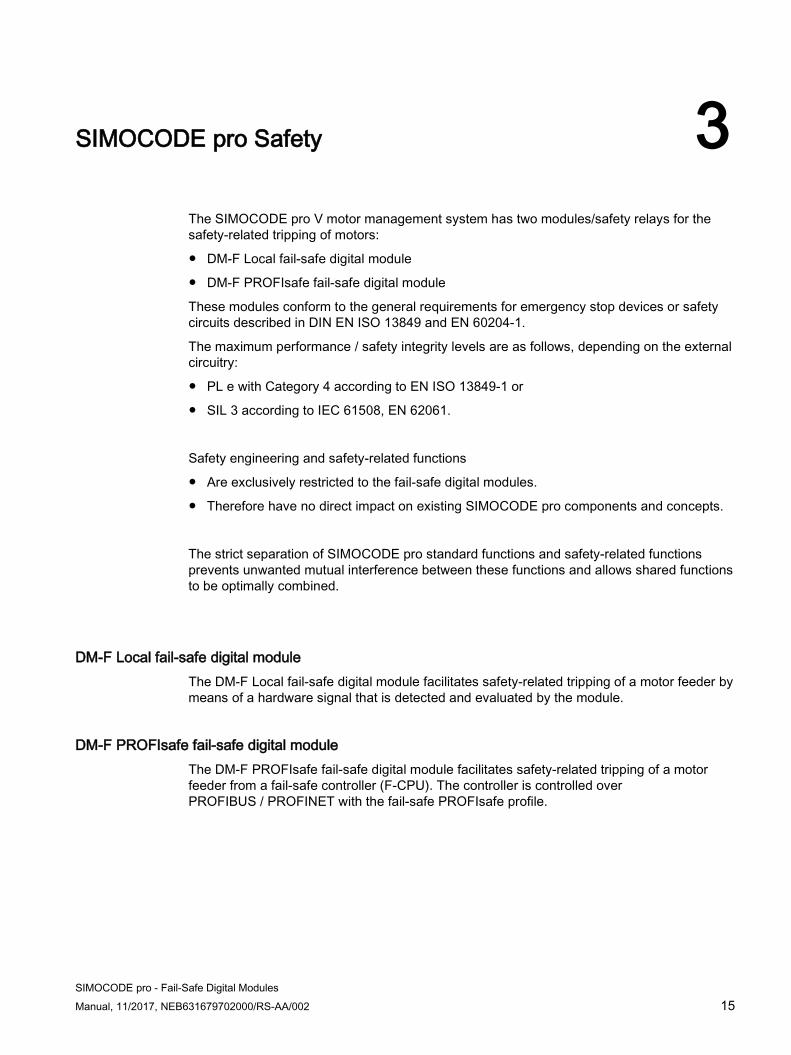
SIMOCODE pro Safety 3The SIMOCODE pro V motor management system has two modules/safety relays for the safety-related tripping of motors:
● DM-F Local fail-safe digital module
● DM-F PROFIsafe fail-safe digital module
These modules conform to the general requirements for emergency stop devices or safety circuits described in DIN EN ISO 13849 and EN 60204-1.
The maximum performance / safety integrity levels are as follows, depending on the external circuitry:
● PL e with Category 4 according to EN ISO 13849-1 or
● SIL 3 according to IEC 61508, EN 62061.
Safety engineering and safety-related functions
● Are exclusively restricted to the fail-safe digital modules.
● Therefore have no direct impact on existing SIMOCODE pro components and concepts.
The strict separation of SIMOCODE pro standard functions and safety-related functions prevents unwanted mutual interference between these functions and allows shared functions to be optimally combined.
DM-F Local fail-safe digital module The DM-F Local fail-safe digital module facilitates safety-related tripping of a motor feeder by means of a hardware signal that is detected and evaluated by the module.
DM-F PROFIsafe fail-safe digital module The DM-F PROFIsafe fail-safe digital module facilitates safety-related tripping of a motor feeder from a fail-safe controller (F-CPU). The controller is controlled over PROFIBUS / PROFINET with the fail-safe PROFIsafe profile.
SIMOCODE pro Safety 3.1 Overview of functions
16 SIMOCODE pro - Fail-Safe Digital Modules
Manual, 11/2017, NEB631679702000/RS-AA/002
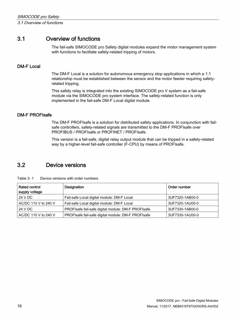
3.1 Overview of functions The fail-safe SIMOCODE pro Safety digital modules expand the motor management system with functions to facilitate safety-related tripping of motors.
DM-F Local The DM-F Local is a solution for autonomous emergency stop applications in which a 1:1 relationship must be established between the sensor and the motor feeder requiring safety-related tripping.
This safety relay is integrated into the existing SIMOCODE pro V system as a fail-safe module via the SIMOCODE pro system interface. The safety-related function is only implemented in the fail-safe DM-F Local digital module.
DM-F PROFIsafe The DM-F PROFIsafe is a solution for distributed safety applications. In conjunction with fail-safe controllers, safety-related signals are transmitted to the DM-F PROFIsafe over PROFIBUS / PROFIsafe or PROFINET / PROFIsafe.
This version is a fail-safe, digital relay output module that can be tripped in a safety-related way by a higher-level fail-safe controller (F-CPU) by means of PROFIsafe.
3.2 Device versions
Table 3- 1 Device versions with order numbers
Rated control supply voltage
Designation Order number
24 V DC Fail-safe Local digital module: DM-F Local 3UF7320-1AB00-0 AC/DC 110 V to 240 V Fail-safe Local digital module: DM-F Local 3UF7320-1AU00-0 24 V DC PROFIsafe fail-safe digital module: DM-F PROFIsafe 3UF7330-1AB00-0 AC/DC 110 V to 240 V PROFIsafe fail-safe digital module: DM-F PROFIsafe 3UF7330-1AU00-0

SIMOCODE pro Safety 3.3 Failsafe DM-F LOCAL digital module
SIMOCODE pro - Fail-Safe Digital Modules Manual, 11/2017, NEB631679702000/RS-AA/002 17
3.3 Failsafe DM-F LOCAL digital module
Safety-related function The safety-related function comprises:
● The safe state is the OFF state (enabling circuits opened)
● Tripping of a motor by controlling the actuators (the contactors that switch the motor onand off) in a safety-related way.
● Safety-related evaluation of
– Hardware signals, e.g. fail-safe output, or
– Sensors, e.g. emergency stop actuators that are detected and evaluated locally, i.e. inthe safety relay.

SIMOCODE pro Safety 3.3 Failsafe DM-F LOCAL digital module
18 SIMOCODE pro - Fail-Safe Digital Modules
Manual, 11/2017, NEB631679702000/RS-AA/002
Standard function (non-safety-related) The non-safety-related standard function comprises:
● Operational control of the actuators (contactors) that switch the motor on and off
● Diagnostic information (e.g. safety-related tripping, fault in the sensor circuit)
The DM-F Local is available in the following versions:
24 V DC:
Figure 3-1 DM-F Local 24 V DC with sensor inputs, feedback and relay enabling circuits, stop category 0 according to EN 60204-1

SIMOCODE pro Safety 3.3 Failsafe DM-F LOCAL digital module
SIMOCODE pro - Fail-Safe Digital Modules Manual, 11/2017, NEB631679702000/RS-AA/002 19
110 to 240 V AC/DC:
Figure 3-2 DM-F Local 110-240 V AC/DC with sensor inputs, feedback and relay enabling circuits, stop category 0 according to EN 60204-1

SIMOCODE pro Safety 3.4 Failsafe DM-F PROFIsafe digital module
20 SIMOCODE pro - Fail-Safe Digital Modules
Manual, 11/2017, NEB631679702000/RS-AA/002
3.4 Failsafe DM-F PROFIsafe digital module
Safety-related function The safety-related function comprises:
● The safe state is the OFF state (enabling circuits opened)
● Tripping of a motor by controlling the actuators (the contactors that switch the motor onand off) in a safety-related way.
● Safety-related evaluation of data that is received from a fail-safe controller (F-CPU) viathe PROFIsafe profile over the bus and system interface.
Standard function (non-safety-related) The non-safety-related standard function comprises
● Operational control of the actuators (contactors) that switch the motor on and off
● Diagnostic information (e.g. safety-related tripping)
The DM-F PROFIsafe fail-safe digital module is available in the following versions:
● 24 V DC:
Figure 3-3 DM-F PROFIsafe 24 V DC with feedback and relay enabling circuits, tripping by means of PROFIsafe, stop category 0 according to EN 60204-1
SIMOCODE pro Safety 3.4 Failsafe DM-F PROFIsafe digital module
SIMOCODE pro - Fail-Safe Digital Modules Manual, 11/2017, NEB631679702000/RS-AA/002 21
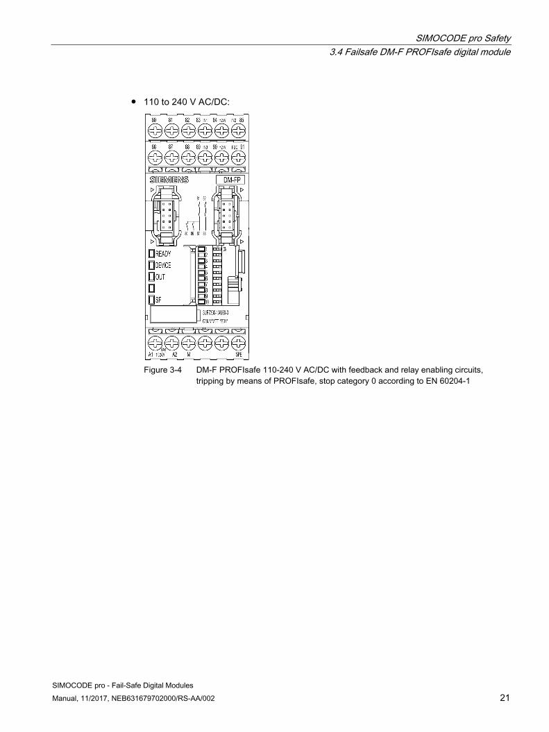
● 110 to 240 V AC/DC:
Figure 3-4 DM-F PROFIsafe 110-240 V AC/DC with feedback and relay enabling circuits, tripping by means of PROFIsafe, stop category 0 according to EN 60204-1

SIMOCODE pro Safety 3.4 Failsafe DM-F PROFIsafe digital module
22 SIMOCODE pro - Fail-Safe Digital Modules
Manual, 11/2017, NEB631679702000/RS-AA/002
SIMOCODE pro - Fail-Safe Digital Modules Manual, 11/2017, NEB631679702000/RS-AA/002 23
Mounting and connection 44.1 General mounting and wiring instructions
Safety notices
WARNING
Danger! High Voltage
Will result in death or serious injury. Can lead to electric shock and burns.
Before starting work, disconnect the system and the device from the power supply.
Note Please note the information in the operating instructions.
Note Short-circuit-proof installation of sensor cables
For use in Category 4 applications as defined by EN ISO 13849-1, the cables for the sensor inputs must be installed in such a manner that they are short-circuit-proof.

Mounting and connection 4.2 Mounting
24 SIMOCODE pro - Fail-Safe Digital Modules
Manual, 11/2017, NEB631679702000/RS-AA/002
4.2 Mounting
Note
Taking the ambient conditions into account, you must install the devices in control cabinets with the IP23, IP43 or IP54 degree of protection.
Note
Please note the information in the operating instructions.
Mounting on a standard rail The 3UF73 fail-safe digital module is suitable for snap mounting on a standard 35 mm rail to DIN EN 60715.
WARNING
Danger! High Voltage
Will result in death or serious injury. Can lead to electric shock and burns.
Disconnect the terminal blocks from the power supply.
Figure 4-1 Mounting on a standard rail (1)

Mounting and connection 4.2 Mounting
SIMOCODE pro - Fail-Safe Digital Modules Manual, 11/2017, NEB631679702000/RS-AA/002 25
Figure 4-2 Mounting on a standard rail (2)
The terminal blocks can be removed in the order a, b and mounted in the order c, d.

Mounting and connection 4.2 Mounting
26 SIMOCODE pro - Fail-Safe Digital Modules
Manual, 11/2017, NEB631679702000/RS-AA/002
Screw mounting As an alternative, the devices can be screw mounted with two additional push-in lugs each (Article No. 3RP1903).
Figure 4-3 Mounting the DM-F with push-in lugs for screw mounting

Mounting and connection 4.3 Connecting
SIMOCODE pro - Fail-Safe Digital Modules Manual, 11/2017, NEB631679702000/RS-AA/002 27
4.3 Connecting
Connecting The fail-safe 3UF73 digital modules are offered with screw terminals.
Refer to the following table for details of the required cable cross-sections and maximum permissible torque data.
Table 4- 1 Cable cross-sections and tightening torques
3UF7320-1A.00-0 3UF7330-1A.00-0
∅ 5 ... 6 mm / PZ2
0.8 ... 1.2 Nm 7 ... 10.3 lb.in
1 x 0.5 ... 4.0 mm2 2 x 0.5 ... 2.5 mm2
2 x 0.5 ... 1.5 mm2 1 x 0.5 ... 2.5 mm2
-
AWG 2 x 20 to 14

Mounting and connection 4.3 Connecting
28 SIMOCODE pro - Fail-Safe Digital Modules
Manual, 11/2017, NEB631679702000/RS-AA/002

SIMOCODE pro - Fail-Safe Digital Modules Manual, 11/2017, NEB631679702000/RS-AA/002 29
Operation 55.1 DM-F LOCAL
5.1.1 Terminals and their meaning
Figure 5-1 DM-F Local, 24 V DC version and 110-240 V AC/DC version

Operation 5.1 DM-F LOCAL
30 SIMOCODE pro - Fail-Safe Digital Modules
Manual, 11/2017, NEB631679702000/RS-AA/002
Table 5- 1 Terminal assignment of DM-F Local
Terminal Meaning 60, 66 Digital module, relay outputs 1 (60) and 2 (66) 61, 67 Relay enabling circuit 1, NO 62, 68 Relay enabling circuit 2, NO Y12, Y22 Sensor input channel 1, channel 2 T1, T2 Supply for sensor inputs (24 V DC, pulsed) Y33 Start button (start after upwards and downwards edge) Y34 Feedback circuit A1 (+) Power supply connection 110 to 240 V AC/DC or +24 V DC A2 (-) N or -24 V M Ground (reference potential for sensor inputs; 3UF7320-1AU00-0 only) 1 Cascade input T3 Supply for sensor inputs (24 V DC, static) SPE 1) System shielding
WARNING
Loss of safety function possible.
For the 24 V DC power supply, always use a power supply according to IEC 60536 protection class III (SELV or PELV).
1)
Note
Connect SIMOCODE pro via terminal SPE with the maximum possible cross-section and with as short a cable as possible to the functional ground of the control cabinet, e.g. to the grounded mounting plate of the control cabinet.
Note
Surge suppressors are required for inductive loads.

Operation 5.1 DM-F LOCAL
SIMOCODE pro - Fail-Safe Digital Modules Manual, 11/2017, NEB631679702000/RS-AA/002 31
5.1.2 LEDs, buttons, and their meanings
Table 5- 2 LEDs on DM-F Local
LED Status Meaning READY Off System interface not connected/supply voltage too low/device defective
Green Device ON/system interface OK Flashing green Device ON/system interface not active or not OK
DEVICE Off Supply voltage too low Green Device ON Flashing green Self-test Yellow Configuration mode Flashing yellow Configuration error Red Device defective or faulty
OUT Off Safety-related output not active Green Safety-related output active Flashing green Feedback circuit not closed although start condition satisfied
IN Off Input not active Green Input active Flashing green Fault detected (e.g. cross-circuit at input, sensor simultaneity not satisfied)
SF Off No group fault Red Group fault (wiring error, cross-circuit, configuration error) Flashing red Group fault (feedback circuit fault, simultaneity condition not satisfied)
1 Off Cross-circuit detection Off Yellow Cross-circuit detection On Flashing yellow Configuration mode, waiting for confirmation Flickering yellow Configuration error
2 Off NC contact/NO contact Yellow NC contact/NC contact Flashing yellow Configuration mode, waiting for confirmation Flickering yellow Configuration error
3 Off 2 x 1-channel Yellow 1 x 2-channel Flashing yellow Configuration mode, waiting for confirmation Flickering yellow Configuration error
4 Off Debouncing time Y12, Y22, Y34 ~ 50 ms Yellow Debouncing time Y12, Y22, Y34 ~ 10 ms Flashing yellow Configuration mode, waiting for confirmation Flickering yellow Configuration error
5 Off Sensor circuit, automatic start Yellow Sensor circuit, monitored start Flashing yellow Configuration mode, waiting for confirmation Flickering yellow Configuration error

Operation 5.1 DM-F LOCAL
32 SIMOCODE pro - Fail-Safe Digital Modules
Manual, 11/2017, NEB631679702000/RS-AA/002
LED Status Meaning 6 Off Cascading input 1, automatic start
Yellow Cascading input 1, monitored start Flashing yellow Configuration mode, waiting for confirmation Flickering yellow Configuration error
7 Off With start-up testing Yellow Without start-up testing Flashing yellow Configuration mode, waiting for confirmation Flickering yellow Configuration error
8 Off Automatic starting after power failure Yellow No automatic starting after power failure Flashing yellow Configuration mode, waiting for confirmation Flickering yellow Configuration error

Operation 5.1 DM-F LOCAL
SIMOCODE pro - Fail-Safe Digital Modules Manual, 11/2017, NEB631679702000/RS-AA/002 33
Function of the SET / RESET button The following flow diagram shows the configuration of the DM-F Local with the "SET / RESET" button:
Figure 5-2 Configuration flow diagram

Operation 5.1 DM-F LOCAL
34 SIMOCODE pro - Fail-Safe Digital Modules
Manual, 11/2017, NEB631679702000/RS-AA/002
Figure 5-3 DM-F Local with SET / RESET button

Operation 5.2 DM-F PROFIsafe
SIMOCODE pro - Fail-Safe Digital Modules Manual, 11/2017, NEB631679702000/RS-AA/002 35
5.2 DM-F PROFIsafe
5.2.1 Terminals and their meaning
Figure 5-4 DM-F PROFIsafe, 24 V version and 110 - 240 V AC/DC version

Operation 5.2 DM-F PROFIsafe
36 SIMOCODE pro - Fail-Safe Digital Modules
Manual, 11/2017, NEB631679702000/RS-AA/002
Table 5- 3 Terminal assignment of DM-F PROFIsafe
Terminal Meaning 80, 86 Digital module, relay outputs 1 (80) and 2 (86) 81, 87 Relay enabling circuit 1, NO 82, 88 Relay enabling circuit 2, NO 83, 85, 89 Digital module, inputs 1, 2, 3 84 Supply for digital module, inputs 1 to 3, 24 V DC 90 (T) Supply for feedback circuit 24 V DC 91 (FBC) Feedback circuit A1 (+) Power supply connection 110 to 240 V AC/DC or +24 V DC A2 (-) N or -24 V M Ground (reference potential for digital module inputs; 3UF7330-1AU00-0 only) SPE 1) System shielding
WARNING
Loss of safety function possible.
For the 24 V DC power supply, always use a power supply according to IEC 60536 protection class III (SELV or PELV).
1)
Note
Connect SIMOCODE pro via terminal SPE with the maximum possible cross-section and with as short a cable as possible to the functional ground of the control cabinet, e.g. to the grounded mounting plate of the control cabinet.
Note
Surge suppressors are required for inductive loads.

Operation 5.2 DM-F PROFIsafe
SIMOCODE pro - Fail-Safe Digital Modules Manual, 11/2017, NEB631679702000/RS-AA/002 37
5.2.2 LEDs, buttons, and their meanings
Table 5- 4 LEDs on DM-F PROFIsafe
LED Status Meaning READY Off System interface not connected/supply voltage too low/device defective
Green Device ON/system interface OK Flashing green Device ON/system interface not active or not OK
DEVICE Off Supply voltage too low Green Device ON Red Device defective or faulty
OUT Off Safety-related output not active Green Safety-related output active Flashing green Feedback circuit not closed although start condition satisfied
SF Off No group fault Red Group fault (PROFIsafe not active, incorrect PROFIsafe address, wiring error, device de-
fective) 1 Yellow PROFIsafe address 1 2 Yellow PROFIsafe address 2 3 Yellow PROFIsafe address 4 4 Yellow PROFIsafe address 8 5 Yellow PROFIsafe address 16 6 Yellow PROFIsafe address 32 7 Yellow PROFIsafe address 64 8 Yellow PROFIsafe address 128 9 Yellow PROFIsafe address 256 10 Yellow PROFIsafe address 512

Operation 5.2 DM-F PROFIsafe
SIMOCODE pro - Fail-Safe Digital Modules 38 Manual, 11/2017, NEB631679702000/RS-AA/002
Function of the SET / RESET button:
● Display of the current PROFIsafe address: Press the SET / RESET button briefly: LEDs 1 to 10 indicate the current PROFIsafe address.
● Resetting of faults (also possible via "TEST/RESET" button on basic unit): Press the SET / RESET button for approx. 3 s: The DM-F PROFIsafe is restarted; but there is no need to switch off the power supply.
Figure 5-5 DM-F PROFIsafe with SET / RESET button

SIMOCODE pro - Fail-Safe Digital Modules Manual, 11/2017, NEB631679702000/RS-AA/002 39
Planning/Configuring 66.1 General remarks
Safety chain A safety chain generally consists of the Sense, Evaluate and Deactivate functions.
Sensing Detecting a safety requirement, e.g.:
● By a safe trip signal, triggered by a fail-safe hardware output signal
● By a tripped emergency stop actuator
● By a trip signal transmitted by a fail-safe controller (F-CPU) via PROFIsafe.
Evaluation The detection of a safety requirement and the safe initiation of the response, e.g. safety-related tripping of the enabling circuits of the fail-safe DM-F Local or DM-F PROFIsafe digital module.
Deactivation The response to an emergency or a risk event, e.g. by deactivating dangerous actuators.
Result The fail-safe digital modules play an active part in evaluation and deactivation within this safety chain.

Planning/Configuring 6.2 Configuring the DM-F LOCAL
40 SIMOCODE pro - Fail-Safe Digital Modules
Manual, 11/2017, NEB631679702000/RS-AA/002
6.2 Configuring the DM-F LOCAL
Note
The safety-related functions can only be configured using the DIP switches.
Table 6- 1 Factory setting
OFF Schematic DIP switch No.
ON
Without cross-circuit detection 1 With cross-circuit detection 1 NC + 1 NO evaluation 2 2 NC evaluation 2 x 1-channel 3 1 x 2-channel Debouncing time for sensor inputs ∼ 50 ms 4 Debouncing time for sensor inputs ∼ 10 ms Sensor input automatic start 5 Sensor input monitored start Cascading input automatic start 6 Cascading input monitored start With start-up testing 7 Without start-up testing Automatic starting after power failure (not permissible in conjunction with start-up testing)
8 No automatic starting after power failure
No function - No function No function - No function
DANGER
Automatic starting after power failure. Risk of death or serious injury.
In the case of automatic starting after a power failure, the enabling circuits are connected without pressing the Start button.
The desired configuration of the DM-F Local can be stored in SIMOCODE pro using the SIMOCODE ES software (e.g. for documentation purposes). The stored configuration is then compared with the actually effective settings on the DM-F Local (i.e., the settings defined with the DIP switches). If the stored configuration is not the same as the effective configuration, the following status message appears: "DM-FL Configuration deviates".

Planning/Configuring 6.3 Device functions of the DM-F LOCAL
SIMOCODE pro - Fail-Safe Digital Modules Manual, 11/2017, NEB631679702000/RS-AA/002 41
6.3 Device functions of the DM-F LOCAL
DIP switch settings, DM-F Local
Table 6- 2 Meaning of the DIP switches, DM-F Local
DIP switch
Parameter Function
1 With / without cross-circuit detection
Cross-circuit detection is only possible with floating sensors. The sensors must be connected between T1 - Y12, Y33 and T2 - Y22, Y34. The device anticipates the T1 terminal test signal at the terminals Y12 and Y33, and the T2 terminal test signal at the terminals Y22 and Y34. The device detects a sensor fault if the signal at the Y12, Y33 or the Y22, Y34 terminals is not identical to the test signals T1, T2. Cross-circuit detection must be deactivated if electronic sensors such as light arrays or laser scanners are connected. In this case, the DM-F Local no longer monitors the sensor inputs for cross-circuits. Usually, the outputs of safety sensors (OSSD) are already monitored for cross-circuits in the sensor itself. If "Without cross-circuit detection" is set on the device, the test outputs T1, T2 are deactivated and may no longer be connected. At the Y12, Y22, Y33, and Y34 inputs, the DM-F Local expects a +24 V DC signal from the same current source as the one from which the device receives its power supply (possible only in the case of DM-F Local-*1AB00) or from T3 (static +24 V DC). In the case of the DM-F Local -1AU00 device version, it is imperative to connect the T3 terminal to the floating sensor contacts due to the electrical isolation between the input circuit and the sensor power supply.
2 Evaluation: 1 NC + 1 NO evaluation / 2 NC evaluation
In addition to 2-channel connection of the same types of sensor contacts (NC / NC), sensors with opposite types of contacts (NC / NO), as are frequently used for electromagnetic switches, can also be evaluated. Make sure that the NC contact is connected to Y12 and the NO contact to Y22.
3 Connection type: 2x 1-channel / 1x 2-channel
• 2 sensors with one contact each (2x 1-channel) (NC / NC). The two sensors are"ANDed". Simultaneity is not monitored.
• 1 sensor with two contacts each (1x 2-channel) (NC / NC). The system expectsboth contacts to be simultaneously open.
4 Debouncing time for sensor inputs 50 ms / 10 ms
Any change in the sensor signal during the debouncing time is not evaluated. • Debouncing time 50 ms: Switch position changes of strongly bouncing contacts
are suppressed (e.g. position switches on heavy protective doors).• Debouncing time 10 ms: The shorter debouncing time permits faster deactivation
of bounce-free sensors (e.g. light arrays).
5 Start mode of sensor input • Automatic start: The enabling circuits are switched to the active position as soonas the starting condition at sensor inputs Y12, Y22, Y34 and terminal 1 have beenfulfilled. The start button connection terminal Y33 is not queried.
• Monitored start: The enabling circuits are switched to the active position as soonas the switch-on condition is satisfied at the sensor inputs Y12, Y22, Y34, and atterminal 1, and the start button at the Y33 terminal is actuated (start at fallingedge).

Planning/Configuring 6.4 Flow diagram of the DM-F LOCAL configuration
42 SIMOCODE pro - Fail-Safe Digital Modules
Manual, 11/2017, NEB631679702000/RS-AA/002
6 Start mode of cascade input
• Automatic start: The enabling circuits are switched to the active position as soonas the switch-on condition at cascading input 1 is satisfied, i.e. as soon as a static+24 V DC signal is present (e.g. from T3).
• Monitored start: The enabling circuits are switched to the active position as soonas the switch-on condition at cascade input 1 is satisfied, i.e. as soon as a static+24 V DC signal is present (e.g. from T3), and the START button at theterminal Y33 is actuated (start at falling edge).
7 Start-up testing After a power failure, startup testing requires that the system operator actuates the sensors at Y12 and Y22 once.
8 Starting after power failure The parameters of the DM-F Local can be defined so that the enabling circuits are automatically switched to the active position after a power failure, i.e. without actuation of the Y33 start button. Requirements: • Y12, Y22 or the cascading input 1 are set to "monitored start".• The switch-on condition at the sensor inputs and at the cascade input is satisfied.• The START button was actuated before the power failure and this was valid, i.e.
the enabling circuits were in the active position.
Function of the cascade input (terminal 1) As an alternative to using the sensor inputs (terminals Y12, Y22), safety-related tripping can also take place via the cascade input (terminal 1).
Note Application / safety relay safety category
If faults can be ruled out (protected laying of the control cable at terminal 1), the application's safety category corresponds to that of the higher-level safety relay.
6.4 Flow diagram of the DM-F LOCAL configuration
Note
The configuration can only be modified after disconnecting the power supply.
Modifications during operation are not accepted. The device is in the configuration mode if you configure it under voltage and then deactivate and reactivate the power supply. The device is therefore in the safe state and all enabling circuits are deactivated.

Planning/Configuring 6.4 Flow diagram of the DM-F LOCAL configuration
SIMOCODE pro - Fail-Safe Digital Modules Manual, 11/2017, NEB631679702000/RS-AA/002 43
Setting the configuration
Figure 6-1 Setting the configuration

Planning/Configuring 6.4 Flow diagram of the DM-F LOCAL configuration
44 SIMOCODE pro - Fail-Safe Digital Modules
Manual, 11/2017, NEB631679702000/RS-AA/002
Displaying the configuration
Figure 6-2 Displaying the configuration
RESET in the event of a fault
Figure 6-3 Reset in the event of a fault

Planning/Configuring 6.5 Interrupt, error, and system messages on the DM-F LOCAL
SIMOCODE pro - Fail-Safe Digital Modules Manual, 11/2017, NEB631679702000/RS-AA/002 45
6.5 Interrupt, error, and system messages on the DM-F LOCAL
Table 6- 3 Messages on the fail-safe DM-F Local digital module
Message Type Description DM-F LOCAL OK Message The DM-F Local is ON. Monitoring - Interval to mandatory testing - Test requirement
Message, warning The enabling circuits have not been switched off and on again for longer than the set monitoring time. The relay contact function of the enabling circuits can only be tested if the contacts are switched.
DM-F safety-related tripping Message, warning, error
The enabling circuits have been tripped in a safety-related way. The motor cannot be switched on again until the enabling circuits of the DM-F module are reclosed.
Wiring Error A wiring error has occurred on the module (short-circuit to ground in the sensor / feedback circuit). Check the wiring of the sensor circuits / feedback circuit and correct the error.
Cross-circuit fault Error A cross-circuit fault has occurred in the sensor circuit of the DM-F Local. Check the wiring of the sensor circuits for cross-circuit faults and correct the error.
Feedback circuit Warning The DM-F Local has detected a fault in the feedback circuit. The feedback circuit must be closed at the time of switching on. Check the feedback circuit.
Simultaneity Warning The DM-F Local has detected a discrepancy error in the 2-channel sensor circuit. Check the switching elements in the sensor circuit.
Enabling circuit closed Status The enabling circuits are closed. DM-F LOCAL configuration mode Status The DM-F Local is in configuration mode. Complete the
configuration (refer to chapter Configuring the DM-F LOCAL (Page 40))
DM-F LOCAL - Actual and preset configuration different
Status The configuration that is effective on the DM-F Local is not identical to the defined configuration.
DM-F LOCAL Waiting for start-up test Status The DM-F Local is in the "Waiting for start-up test" status (after a power failure, start-up testing requires that the system operator actuates the sensors at Y12 and Y22 once).
No module voltage Status The supply voltage on the module is either too low or there is no voltage. Check that the A1 / A2 terminals are correctly wired. The module could be defective. Replace the module (refer to chapter Replacing a DM-F (Page 55))

Planning/Configuring 6.6 Configuring the DM-F PROFIsafe and integrating it into the fail-safe automation system using PROFIBUS/ PROFIsafe or PROFINET/PROFIsafe
46 SIMOCODE pro - Fail-Safe Digital Modules
Manual, 11/2017, NEB631679702000/RS-AA/002
6.6 Configuring the DM-F PROFIsafe and integrating it into the fail-safe automation system using PROFIBUS/ PROFIsafe or PROFINET/PROFIsafe
Required manuals Depending on the application, you need the following additional manuals to work with the DM-F PROFIsafe fail-safe digital module:
● SIMOCODE pro – System Manual(https://support.industry.siemens.com/cs/ww/en/view/109743957) including safety andcommissioning instructions for hazardous areas
● System manual SIMATIC Industrial Software Safety Engineering in SIMATIC S7(http://support.automation.siemens.com/WW/view/en/12490443). This manual providesyou with
– An overview of the fail-safe S7 Distributed Safety and S7 F/H automation systems
– Information about the optimal fail-safe system for implementing a particularautomation task
● Manual SIMATIC S7 Industrial Software Distributed Safety - Configuring andProgramming. (http://support.automation.siemens.com/WW/view/en/22099875). Thismanual describes
– How to configure the F-CPU and the F-I/O
– How to program the F-CPU in an F-FBD or an F-LAD
● Manual SIMATIC Industrial Software S7 F/FH Systems - Configuring and Programming.(https://support.industry.siemens.com/cs/ww/en/view/109742100). This manual describes
– How to configure the F-CPU and the F-I/O
– How to program the F-CPU in a CFC.
● Manual SIMATIC Industrial Software SIMATIC Safety - Configuring and Programming(https://support.industry.siemens.com/cs/ww/en/view/54110126). This manual describesthe use of the "STEP 7 Safety Advanced" and "STEP 7 Safety Basic" option packages.

Planning/Configuring 6.6 Configuring the DM-F PROFIsafe and integrating it into the fail-safe automation system using PROFIBUS/
PROFIsafe or PROFINET/PROFIsafe
SIMOCODE pro - Fail-Safe Digital Modules Manual, 11/2017, NEB631679702000/RS-AA/002 47
Integrating the DM-F PROFIsafe into the fail-safe automation system using PROFIBUS / PROFIsafe or PROFINET / PROFIsafe
From the point of view of the fail-safe part of the controller, which transmits fail-safe signals over PROFIBUS / PROFIsafe or PROFINET / PROFIsafe, the DM-F PROFIsafe is a fail-safe digital output. This digital output allows the two relay enabling circuits of the DM-F PROFIsafe to be simultaneously energized or tripped in a safety-related way. All other SIMOCODE pro and DM-F PROFIsafe functions are irrelevant from this perspective.
Address assignment Out of the addresses assigned on the DM-F PROFIsafe, the following output address in the F-CPU is reserved for user data:
Byte in F-CPU Bit 7 Bit 6 Bit 5 Bit 4 Bit 3 Bit 2 Bit 1 Bit 0 X+0 - - - - - - - Output
WARNING
Address access
You are only allowed to access the address reserved for user data (output byte x, bit 0).
The other address areas assigned to the DM-F PROFIsafe are reserved for safety-related communication between the DM-F PROFIsafe and the F-CPU in accordance with PROFIsafe.
Further information about F-I/O access You can find more detailed information about F-I/O access in the following manuals:
● SIMATIC S7 Industrial Software Distributed Safety - Configuring and Programming.(http://support.automation.siemens.com/WW/view/en/22099875)
● SIMATIC Industrial Software S7 F/FH Systems - Configuring and Programming.(https://support.industry.siemens.com/cs/ww/en/view/109742100)
● SIMATIC Industrial Software SIMATIC Safety - Configuring and Programming(https://support.industry.siemens.com/cs/ww/en/view/54110126)
Planning/Configuring 6.6 Configuring the DM-F PROFIsafe and integrating it into the fail-safe automation system using PROFIBUS/ PROFIsafe or PROFINET/PROFIsafe
48 SIMOCODE pro - Fail-Safe Digital Modules
Manual, 11/2017, NEB631679702000/RS-AA/002
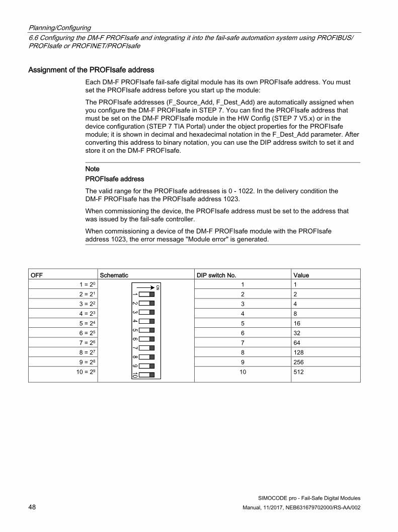
Assignment of the PROFIsafe address Each DM-F PROFIsafe fail-safe digital module has its own PROFIsafe address. You must set the PROFIsafe address before you start up the module:
The PROFIsafe addresses (F_Source_Add, F_Dest_Add) are automatically assigned when you configure the DM-F PROFIsafe in STEP 7. You can find the PROFIsafe address that must be set on the DM-F PROFIsafe module in the HW Config (STEP 7 V5.x) or in the device configuration (STEP 7 TIA Portal) under the object properties for the PROFIsafe module; it is shown in decimal and hexadecimal notation in the F_Dest_Add parameter. After converting this address to binary notation, you can use the DIP address switch to set it and store it on the DM-F PROFIsafe.
Note PROFIsafe address
The valid range for the PROFIsafe addresses is 0 - 1022. In the delivery condition the DM-F PROFIsafe has the PROFIsafe address 1023.
When commissioning the device, the PROFIsafe address must be set to the address that was issued by the fail-safe controller.
When commissioning a device of the DM-F PROFIsafe module with the PROFIsafe address 1023, the error message "Module error" is generated.
OFF Schematic DIP switch No. Value 1 = 20 1 1 2 = 21 2 2 3 = 22 3 4 4 = 23 4 8 5 = 24 5 16 6 = 25 6 32 7 = 26 7 64 8 = 27 8 128 9 = 28 9 256
10 = 29 10 512

Planning/Configuring 6.6 Configuring the DM-F PROFIsafe and integrating it into the fail-safe automation system using PROFIBUS/
PROFIsafe or PROFINET/PROFIsafe
SIMOCODE pro - Fail-Safe Digital Modules Manual, 11/2017, NEB631679702000/RS-AA/002 49
To store the set PROFIsafe address:
The set PROFIsafe address is stored after switching on the power supply.
● Briefly press the SET / RESET button: LEDs 1 to 10 indicate the current PROFIsafeaddress.
Figure 6-4 SET / RESET button
NOTICE
PROFIsafe address
The PROFIsafe address 1023 is set in the delivery state.
You must set a valid address in the range from 0 to 1022.

Planning/Configuring 6.6 Configuring the DM-F PROFIsafe and integrating it into the fail-safe automation system using PROFIBUS/ PROFIsafe or PROFINET/PROFIsafe
50 SIMOCODE pro - Fail-Safe Digital Modules
Manual, 11/2017, NEB631679702000/RS-AA/002
Displaying the set PROFIsafe address and the DIP switch setting with SIMOCODE ES (SIMOCODE ES 2007) or SIMOCODE ES (TIA-Portal)
You can display the PROFIsafe address set on the DM-F PROFIsafe online. To do this, proceed as follows:
● Change to the online mode.
– SIMOCODE ES 2007: "Open switching device online"
– SIMOCODE ES (TIA Portal): "Go online"
● You can find the currently effective PROFIsafe address as follows:
DM-F PROFIsafe with SIMOCODE pro V:
– SIMOCODE ES 2007: In the parameter tree under "Bus parameter"
– SIMOCODE ES (TIA-Portal): Under "Parameter → Fieldbus interface".
DM-F PROFIsafe with SIMOCODE pro V PN:
– SIMOCODE ES 2007: In the parameter tree under "PROFINET parameter"
– SIMOCODE ES (TIA-Portal): Under "Parameter → Fieldbus interface".
You can find the DIP switch setting for the PROFIsafe address as follows:
● SIMOCODE ES 2007: Under "Target System → Actual configuration"
● SIMOCODE ES (TIA-Portal): Under "Commissioning → Actual configuration"
Configuring SIMOCODE pro V with DM-F PROFIsafe For the configuration of SIMOCODE pro V with the DM-F PROFIsafe fail-safe digital module, the following options are available to you:
1st option:
By GSD / GSDML for use in S7 systems and "non-S7 systems" as fail-safe standard slave:
Note Option package
Note that you still require the option package appropriate for the respective engineering system. If you use, for example, the GSD in STEP 7 classic, you require Distributed Safety or F-Systems. • STEP 7 (TIA Portal)
– STEP 7 Safety (TIA Portal)

Planning/Configuring 6.6 Configuring the DM-F PROFIsafe and integrating it into the fail-safe automation system using PROFIBUS/
PROFIsafe or PROFINET/PROFIsafe
SIMOCODE pro - Fail-Safe Digital Modules Manual, 11/2017, NEB631679702000/RS-AA/002 51
2nd option:
By means of STEP 7 classic (V5.2 or higher) in connection with the object manager (OM) SIMOCODE pro (contained in SIMOCODE ES 2007) SIMOCODE ES 2007+SP2 or higher:
● PROFIBUS: See Manual SIMOCODE pro - Communication.(https://support.industry.siemens.com/cs/ww/en/view/109743960), Chapter2.1.5.5 "Integration of SIMOCODE pro as an S7 slave via OM SIMOCODE pro"
● PROFINET: See Manual SIMOCODE pro - Communication.(https://support.industry.siemens.com/cs/ww/en/view/109743960), Chapter2.2.7 "Integration of SIMOCODE pro V PN in SIMATIC STEP 7 V5 via OM SIMOCODEpro"
Note Option package
Note that you still require the option package appropriate for the respective engineering system. • S7 Distributed Safety (when using the DM-F PROFIsafe fail-safe digital module in the
safety engineering for factory automation) • S7 F Systems, V6.1 and higher (when using the DM-F PROFIsafe in the safety
engineering for process automation)
3rd option:
Using STEP 7 TIA Portal V12 SP1 and higher
Note Option package
Note that you still require the option package appropriate for the respective engineering system. STEP 7 Safety (TIA Portal) V12 SP1 and higher

Planning/Configuring 6.6 Configuring the DM-F PROFIsafe and integrating it into the fail-safe automation system using PROFIBUS/ PROFIsafe or PROFINET/PROFIsafe
52 SIMOCODE pro - Fail-Safe Digital Modules
Manual, 11/2017, NEB631679702000/RS-AA/002
Setting of the F-monitoring time A valid, current safety telegram must be received from the F-CPU within the monitoring time. This ensures that failures or errors are detected and suitable responses triggered, to enable the fail-safe system to be set to a safe state.
The specified monitoring time should be sufficiently long for
● On the one hand, telegram delays to be tolerated by the communication system, and
● On the other, for the error reaction function to respond promptly in the event of a fault(e.g. if the connection is interrupted).
You can find the F-monitoring time under the object properties for the PROFIsafe module:
● in STEP 7 V5.x under parameter "F_WD_Time"
● in STEP 7 (TIA-Portal) under "Parameter → F-monitoring time"
Note F-monitoring time
Note that the preset F-monitoring time of 250 ms may need to be adapted.
Further information is available • in the manual SIMATIC Industrial Software Safety Engineering in SIMATIC S7
(http://support.automation.siemens.com/WW/view/en/12490443) in the following chapters: – A1 "Configuring monitoring times (SIMATIC Safety - Configuring and Programming)"– A.3.2 "Minimum monitoring time for safety-related communication between the F-CPU
and the F-I/O (S7 Distributed Safety)"– A.4.2 "Minimum monitoring time for safety-related communication between the F-CPU
and the F-I/O (S7 F/FH Systems)"• in the manual "SIMATIC Safety - Configuring and Programming" manual
(https://support.industry.siemens.com/cs/ww/en/view/54110126) in the following chapters:– A.1.2 "Minimum monitoring time for safety-related communication between the F-CPU
and the F-I/O"

Planning/Configuring 6.6 Configuring the DM-F PROFIsafe and integrating it into the fail-safe automation system using PROFIBUS/
PROFIsafe or PROFINET/PROFIsafe
SIMOCODE pro - Fail-Safe Digital Modules Manual, 11/2017, NEB631679702000/RS-AA/002 53
Integrating SIMOCODE pro V into S7 F/H Systems with DM-F PROFIsafe
Note Prerequisite
You must have Version 6.1 or a higher software version in order to integrate SIMOCODE pro V into F-Systems with the DM-F PROFIsafe.
Access to the fail-safe output of the DM-F PROFIsafe, which switches the relay enabling circuits, is via the F-channel driver block F_CH_BO. This block is provided for data type BOOL outputs of fail-safe DP standard slaves via the GSD. It is also used if SIMOCODE pro V is integrated with PROFIsafe via the Object Manager (OM) SIMOCODE pro.
More information: You can find more information in the manual SIMATIC Industrial Software S7 F/FH Systems - Configuring and Programming. (https://support.industry.siemens.com/cs/ww/en/view/109742100), Chapter 5.5 "Configuring fail-safe DP/Standard Slaves//IO-Standard Devices".
Integrating SIMOCODE pro V into S7 Distributed Safety with DM-F PROFIsafe
Note Prerequisite
You must have Version V5.4 + SP5 or a higher software version in order to integrate SIMOCODE pro V into S7 Distributed Safety with the DM-F PROFIsafe.
More information: See manual SIMATIC S7 Industrial Software Distributed Safety - Configuring and Programming. (http://support.automation.siemens.com/WW/view/en/22099875).
Integrating SIMOCODE pro V into STEP 7 Safety (TIA Portal) with DM-F PROFIsafe
Note Prerequisite
You must have Version V12 SP1 or a higher software version in order to integrate SIMOCODE pro V into STEP7 Safety Advanced or STEP 7 Safety Basic with the DM-F PROFIsafe.
More information: See manual SIMATIC Industrial Software SIMATIC Safety - Configuring and Programming (https://support.industry.siemens.com/cs/ww/en/view/54110126).

Planning/Configuring 6.7 Interrupt, error, and system messages on DM-F PROFIsafe
54 SIMOCODE pro - Fail-Safe Digital Modules
Manual, 11/2017, NEB631679702000/RS-AA/002
General instructions for integration into the fail-safe program
Monitoring the feedback circuit in the fail-safe controller
The DM-F PROFIsafe fail-safe digital module has an internal function for monitoring the feedback circuit of the switching contactors. As a result of this function, there is no need for the circuit state of the contactors to be monitored by the user program in the fail-safe controller. However, the feedback circuit state is available as an input in the SIMOCODE pro system and can be processed if required.
Note Closing the relay enabling circuits
Note that the closure of the relay enabling circuits does not necessarily have to be linked to a change in the feedback circuit state.
Reason: Motor contactor switching is also determined by the circuit state of the relay outputs.
6.7 Interrupt, error, and system messages on DM-F PROFIsafe
Table 6- 4 Messages on the fail-safe DM-F PROFIsafe digital module
Message Type Description DM-F PROFIsafe active Message The DM-F PROFIsafe is in the "PROFIsafe active" status. Monitoring – Interval for mandatory testing
Message, warning
The enabling circuits have not been switched off and on again for longer than the set monitoring time. The relay contact function of the enabling circuits can only be tested if the contacts are switched.
DM-F safety-related tripping Message, warning, error
The enabling circuits have been tripped in a safety-related way. The motor cannot be switched on again until the enabling circuits of the DM-F module are reclosed.
Wiring Error A wiring error has occurred on the module (short-circuit to ground in the sensor / feedback circuit). Check the wiring of the sensor circuits / feedback circuit and correct the error.
Feedback circuit Warning The DM-F PROFIsafe has detected a fault in the feedback circuit. The feedback circuit must be closed at the time of switching on. Check the feedback circuit.
Enabling circuit closed Status The enabling circuits are closed. Incorrect PROFIsafe address or incorrect PROFIsafe parameters
Status The parameters of the PROFIsafe profile defined in the fail-safe controller are incorrect / the set PROFIsafe address is not identical to the configured address (refer to Chapter "Configuring the DM-F PROFIsafe and integrating it into the fail-safe automation system using PROFIBUS/PROFIsafe or PROFINET/PROFIsafe (Page 46)").
No module voltage Status The supply voltage on the module is either too low or there is no voltage. Check that the A1 / A2 terminals are correctly wired. The module could be defective. Replace the module (refer to Chapter "Replacing a DM-F (Page 55)").
SIMOCODE pro - Fail-Safe Digital Modules Manual, 11/2017, NEB631679702000/RS-AA/002 55
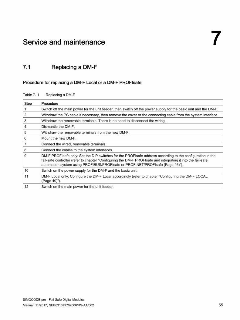
Service and maintenance 77.1 Replacing a DM-F
Procedure for replacing a DM-F Local or a DM-F PROFIsafe
Table 7- 1 Replacing a DM-F
Step Procedure 1 Switch off the main power for the unit feeder, then switch off the power supply for the basic unit and the DM-F. 2 Withdraw the PC cable if necessary, then remove the cover or the connecting cable from the system interface. 3 Withdraw the removable terminals. There is no need to disconnect the wiring. 4 Dismantle the DM-F. 5 Withdraw the removable terminals from the new DM-F. 6 Mount the new DM-F. 7 Connect the wired, removable terminals. 8 Connect the cables to the system interfaces. 9 DM-F PROFIsafe only: Set the DIP switches for the PROFIsafe address according to the configuration in the
fail-safe controller (refer to chapter "Configuring the DM-F PROFIsafe and integrating it into the fail-safe automation system using PROFIBUS/PROFIsafe or PROFINET/PROFIsafe (Page 46)").
10 Switch on the power supply for the DM-F and the basic unit. 11 DM-F Local only: Configure the DM-F Local accordingly (refer to chapter "Configuring the DM-F LOCAL
(Page 40)"). 12 Switch on the main power for the unit feeder.

Service and maintenance 7.1 Replacing a DM-F
56 SIMOCODE pro - Fail-Safe Digital Modules
Manual, 11/2017, NEB631679702000/RS-AA/002

SIMOCODE pro - Fail-Safe Digital Modules Manual, 11/2017, NEB631679702000/RS-AA/002 57
External circuitry 88.1 Sensor circuitry for the DM-F LOCAL
Defining the DM-F parameters according to the sensor circuitry
Table 8- 1 Defining the DM-F parameters according to the sensor circuitry, 2-channel with cross-circuit detection
DIP switch Description Typical circuit diagram 1 2 3 4 5 6 7 8 1 1 1 — 1 — — — 2-channel, with cross-circuit detection, with
monitored start DM-F LOCAL, 2-channel, with cross-circuit detection and monitored start
(Page 64) 1 1 1 — 0 0 — — 2-channel, with cross-circuit detection, with
automatic start DM-F LOCAL, 2-channel, with cross-circuit detection and automatic start
(Page 65) 1 0 1 — 1 — — — NC and NO contacts with cross-circuit detection,
with monitored start DM-F Local, NC and NO contacts, with
cross-circuit detection and monitored start (Page 66)
1 0 1 — 0 0 — — NC and NO contacts with cross-circuit detection, with automatic start
DM-F LOCAL, NC and NO contacts, with cross-circuit detection and automatic start
(Page 67) 0 1 1 — 1 — — — Fail-safe electronic outputs (current sourcing /
current sinking) with monitored start DM-F LOCAL in conjunction with failsafe
electronic outputs (current sourcing / current sinking) with monitored start
(Page 68) 0 1 1 — 0 0 — — Fail-safe electronic outputs (current sourcing)
with automatic start DM-F LOCAL in conjunction with failsafe electronic outputs (current sourcing) with
automatic start (Page 69)
— = Switch position dependent on further requirements

External circuitry 8.1 Sensor circuitry for the DM-F LOCAL
58 SIMOCODE pro - Fail-Safe Digital Modules
Manual, 11/2017, NEB631679702000/RS-AA/002
Table 8- 2 Defining the DM-F parameters according to the sensor circuitry, 2-channel without cross-circuit detection
DIP switch Description Typical circuit diagram 1 2 3 4 5 6 7 8 0 1 0 — 1 — — — 2 x 1-channel, without cross-circuit detection,
with monitored start DM-F LOCAL, 2 x 1-channel, without cross-
circuit detection, with monitored start (Page 70)
0 1 0 — 0 0 — — 2 x 1-channel, without cross-circuit detection, with automatic start
DM-F LOCAL, 2 x 1-channel, without cross-circuit detection, with automatic start
(Page 71)
— = Switch position dependent on further requirements
Key:
DIP switch Meaning 0 = (OFF) Meaning 1 = (ON) 1 Without cross-circuit detection With cross-circuit detection 2 NC contact/NO contact evaluation NC contact/NC contact evaluation 3 2 x 1-channel 1 x 2-channel 4 Debouncing time for sensor inputs 50 ms Debouncing time for sensor inputs 10 ms 5 Sensor input automatic start Sensor input monitored start 6 Cascading input automatic start Cascading input monitored start 7 With start-up testing Without start-up testing 8 Automatic starting after power failure (not permissible in
conjunction with start-up testing) No automatic starting after power failure
9 No function No function 10 No function No function

SIMOCODE pro - Fail-Safe Digital Modules Manual, 11/2017, NEB631679702000/RS-AA/002 59
Typical circuit diagrams 99.1 Introduction
Working with the typical circuit diagrams The typical circuit diagrams are intended to help you generate your own circuit diagrams for different applications. They have a modular structure and are divided into recommendations for the sensor circuit (DM-F Local fail-safe digital module only) and for the actuator circuit, including the feedback circuit for monitoring the actuators.
The examples are designed for various safety requirements in accordance with IEC 61508/62061 and EN ISO 13849-1, taking into account the most frequently used motor control functions such as direct starter, reversing starter, star-delta starter, etc.
Sensor circuit The sensor circuit is the part of the circuit that describes the possible options for connecting emergency stop control devices or fail-safe digital output signals to the DM-F Local fail-safe digital module.
Actuator circuit The actuator circuit is the part of the circuit that is required to control the contactors used for safety-related tripping.
Feedback circuit The feedback circuit is used to monitor the controlled actuators (e.g. contactors) by means of positively driven NC contacts connected in series. The feedback circuit must be closed in order to activate the actuator circuit.
Note
The maximum safety integrity level (SIL) or performance level (PL) that can be achieved in practice also depends on the sensors and actuators that are used.

Typical circuit diagrams 9.1 Introduction
60 SIMOCODE pro - Fail-Safe Digital Modules
Manual, 11/2017, NEB631679702000/RS-AA/002
Generating circuit diagrams The following example of a reversing starter illustrates the basic principle behind the typical circuit diagrams.
The complete circuit diagram is comprised of the following components:
Main circuit Depending on the SIMOCODE pro control function and the maximum SIL / PL, the main circuit contains the motor contactors and – if required – an incoming supply contactor as an additional tripping option.
For the arrangement of the motor contactors depending on the control function, please refer to the typical circuit diagrams in the system manual for SIMOCODE pro, chapter E.
Sensor circuit (only in conjunction with DM-F Local) Select a typical circuit diagram for the sensor circuit according to your requirements.
Actuator circuit with feedback circuit To select a typical circuit diagram for the actuator circuit, proceed as follows:
1. Select the desired SIMOCODE pro control function.
2. Select a typical circuit diagram with or without an incoming supply contactor, dependingon the maximum SIL / PL. Example: Reversing starter with safety-related tripping via anemergency stop control device, maximum level SIL 3 or PL e (see circuit diagram).
The following warning applies to both circuit examples (see below):
WARNING
Loss of safety function possible.
Use only the specified fuses.

Typical circuit diagrams 9.1 Introduction
SIMOCODE pro - Fail-Safe Digital Modules Manual, 11/2017, NEB631679702000/RS-AA/002 61
(1) Sensor circuit Actuator circuit Local operation Protective circuit required to suppress surge voltages!
S10 Emergency stop Q1 = Incoming supply contactor S1 = CW rotation S11 Start Q2 = Motor contactor CW S2 = Off
Q3 = Motor contactor CCW S3 = CCW rotation
Figure 9-1 Typical circuit diagram of a reversing starter with safety-related tripping via an emergency stop control device, maximum level SIL 3 or PL e

Typical circuit diagrams 9.1 Introduction
62 SIMOCODE pro - Fail-Safe Digital Modules
Manual, 11/2017, NEB631679702000/RS-AA/002
(1) Actuator circuit Local operation Protective circuit required to suppress surge voltages!
Q1 = Incoming supply contactor S1 = CW rotation Q2 = Motor contactor CW S2 = Off Q3 = Motor contactor CCW S3 = CCW rotation
Figure 9-2 Typical circuit diagram of a reversing starter with safety-related tripping via PROFIBUS / PROFIsafe or PROFINET / PROFIsafe, maximum level SIL 3 or PL e

Typical circuit diagrams 9.2 DM-F Local, sensor circuits
SIMOCODE pro - Fail-Safe Digital Modules Manual, 11/2017, NEB631679702000/RS-AA/002 63
9.2 DM-F Local, sensor circuits
Overview of DM-F Local, sensor circuit This chapter contains typical circuit diagrams showing the structure of the sensor circuit of the fail-safe DM-F Local digital module:
● With and without cross-circuit detection between sensor circuits
● 1 or 2-channel design of the sensor circuit
● Monitored or automatic start if the switch-off condition is no longer satisfied
● NC or NC / NO combination in the sensor circuit
● Fail-safe electronic output instead of NC contacts in the sensor circuit

Typical circuit diagrams 9.2 DM-F Local, sensor circuits
64 SIMOCODE pro - Fail-Safe Digital Modules
Manual, 11/2017, NEB631679702000/RS-AA/002
9.2.1 DM-F LOCAL, 2-channel, with cross-circuit detection and monitored start 3UF7320-1A.00-0
● With cross-circuit detection
● 2 NC contacts
● 2-channel
● Sensor input monitored start
Figure 9-3 Circuit diagram, 3UF7320-1A.00-0 with cross-circuit detection, 2 NC contacts, 2-channel, monitored start
DIP switch 1 2 3 4 5 6 7 8 1 1 1 - 1 - - - - : Switch position dependent on further requirements Max. levels • Safety Integrity Level in accordance with IEC 61508/EN 62061 to SIL 3• Performance Level in accordance with EN ISO 13849-1 to PL e
DIP switch settings, 3UF7320-1A.00-0 with cross-circuit detection, 2 NC contacts, 2-channel, monitored start
Typical circuit diagrams 9.2 DM-F Local, sensor circuits
SIMOCODE pro - Fail-Safe Digital Modules Manual, 11/2017, NEB631679702000/RS-AA/002 65
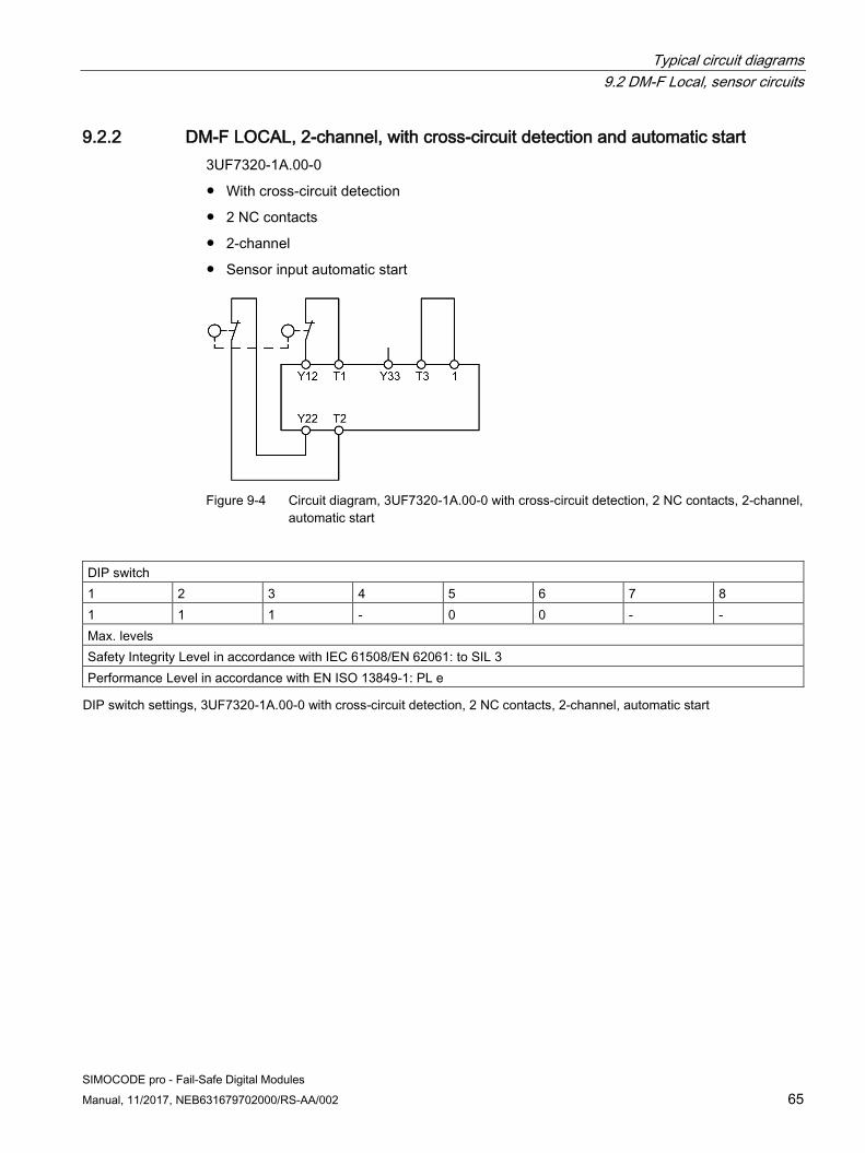
9.2.2 DM-F LOCAL, 2-channel, with cross-circuit detection and automatic start 3UF7320-1A.00-0
● With cross-circuit detection
● 2 NC contacts
● 2-channel
● Sensor input automatic start
Figure 9-4 Circuit diagram, 3UF7320-1A.00-0 with cross-circuit detection, 2 NC contacts, 2-channel, automatic start
DIP switch 1 2 3 4 5 6 7 8 1 1 1 - 0 0 - - Max. levels Safety Integrity Level in accordance with IEC 61508/EN 62061: to SIL 3 Performance Level in accordance with EN ISO 13849-1: PL e
DIP switch settings, 3UF7320-1A.00-0 with cross-circuit detection, 2 NC contacts, 2-channel, automatic start
Typical circuit diagrams 9.2 DM-F Local, sensor circuits
66 SIMOCODE pro - Fail-Safe Digital Modules
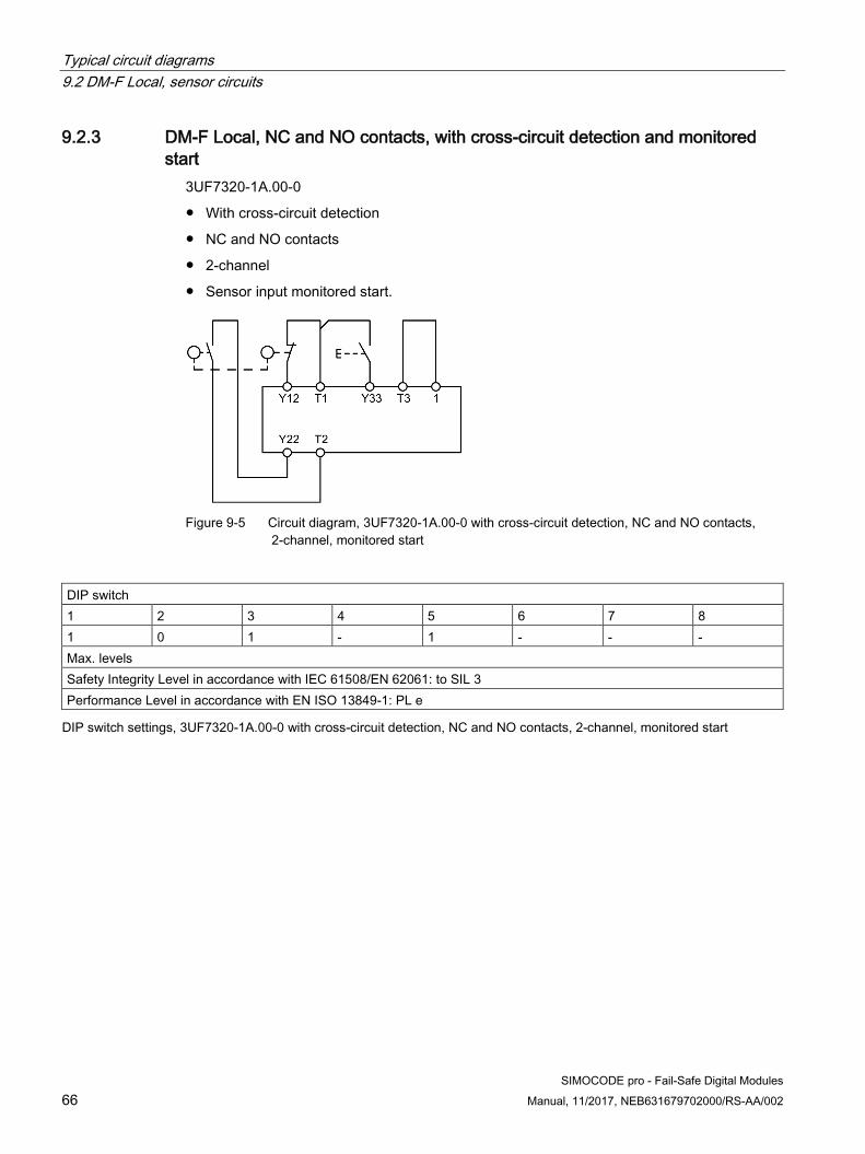
Manual, 11/2017, NEB631679702000/RS-AA/002
9.2.3 DM-F Local, NC and NO contacts, with cross-circuit detection and monitored start
3UF7320-1A.00-0
● With cross-circuit detection
● NC and NO contacts
● 2-channel
● Sensor input monitored start.
Figure 9-5 Circuit diagram, 3UF7320-1A.00-0 with cross-circuit detection, NC and NO contacts, 2-channel, monitored start
DIP switch 1 2 3 4 5 6 7 8 1 0 1 - 1 - - - Max. levels Safety Integrity Level in accordance with IEC 61508/EN 62061: to SIL 3 Performance Level in accordance with EN ISO 13849-1: PL e
DIP switch settings, 3UF7320-1A.00-0 with cross-circuit detection, NC and NO contacts, 2-channel, monitored start

Typical circuit diagrams 9.2 DM-F Local, sensor circuits
SIMOCODE pro - Fail-Safe Digital Modules Manual, 11/2017, NEB631679702000/RS-AA/002 67
9.2.4 DM-F LOCAL, NC and NO contacts, with cross-circuit detection and automatic start
3UF7320-1A.00-0
● With cross-circuit detection
● NC and NO contacts
● 2-channel
● Sensor input automatic start.
Figure 9-6 Circuit diagram, 3UF7320-1A.00-0 with cross-circuit detection, NC and NO contacts, 2-channel, automatic start
DIP switch 1 2 3 4 5 6 7 8 1 0 1 - 0 0 - - Max. levels Safety Integrity Level in accordance with IEC EN 61508/62061: to SIL 3 Performance Level in accordance with EN ISO 13849-1: PL e
DIP switch settings, 3UF7320-1A.00-0 with cross-circuit detection, NC and NO contacts, 2-channel, automatic start

Typical circuit diagrams 9.2 DM-F Local, sensor circuits
68 SIMOCODE pro - Fail-Safe Digital Modules
Manual, 11/2017, NEB631679702000/RS-AA/002
9.2.5 DM-F LOCAL in conjunction with failsafe electronic outputs (current sourcing / current sinking) with monitored start
3UF7320-1AB00-0 / 3UF7320-1AU00-0 (e.g. fail-safe digital output module with electronic outputs SM 326, F-DO 8xDC 24V/2A PM, Article No. 6ES7326-2BF41-0AB0)
● Fail-safe digital output module (current sourcing / current sinking)
● DM-F Local without cross-circuit detection
● DM-F Local 2-channel
● DM-F Local sensor input monitored start
Figure 9-7 Circuit diagram, 3UF7320-1AB00-0 / 3UF7320-1AU00-0, fail-safe digital output module, current sourcing / current sinking, without cross-circuit detection, 2-channel, monitored start
DIP switch 1 2 3 4 5 6 7 8 0 1 1 - 1 - - - Max. levels Safety Integrity Level in accordance with IEC 61508/EN 62061: to SIL 3 Performance Level in accordance with EN ISO 13849-1: PL e
DIP switch settings, 3UF7320-1AB00-0 / 3UF7320-1AU00-0, fail-safe digital output module, current sourcing / current sinking, without cross-circuit detection, 2-channel, monitored start

Typical circuit diagrams 9.2 DM-F Local, sensor circuits
SIMOCODE pro - Fail-Safe Digital Modules Manual, 11/2017, NEB631679702000/RS-AA/002 69
9.2.6 DM-F LOCAL in conjunction with failsafe electronic outputs (current sourcing) with automatic start
3UF7320-1AB00-0 / 3UF7320-1AU00-0
Fail-safe digital output module, current sourcing (e.g. fail-safe digital output module SM 326 DO10x DC 24 V/2 A, Article No. 6ES7 326-2BF00-0AB0, 6ES7 326-2BF40-0AB0)
● DM-F Local without cross-circuit detection
● DM-F Local 2-channel
● DM-F Local sensor input with automatic start
Figure 9-8 Circuit diagram, 3UF7320-1AB00-0 / 3UF7320-1AU00-0, fail-safe digital output module, current sourcing, without cross-circuit detection, 2-channel, with automatic start
DIP switch 1 2 3 4 5 6 7 8 0 1 1 - 0 0 - - Max. levels Safety Integrity Level in accordance with IEC 61508/EN 62061: to SIL 1 Performance Level in accordance with EN ISO 13849-1: to PL c
DIP switch settings, 3UF7320-1AB00-0 / 3UF7320-1AU00-0, fail-safe digital output module, current sourcing, without cross-circuit detection, 2-channel, with automatic start
WARNING
Cross-circuit between P 24 V and DO
If there is an existing cross-circuit between P 24 V and DO, the controlled actuator will no longer be switched off.
To avoid cross-circuits between P 24V and DO, you must lay the cables for the connection of the actuators between the signal group and the actuator in a cross-circuit proof manner (e.g. as separately sheathed cables or in independent cable ducts).
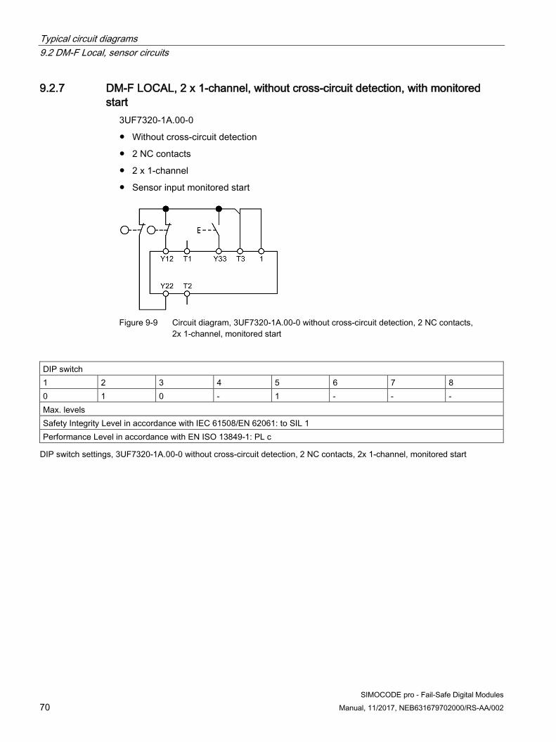
Typical circuit diagrams 9.2 DM-F Local, sensor circuits
70 SIMOCODE pro - Fail-Safe Digital Modules
Manual, 11/2017, NEB631679702000/RS-AA/002
9.2.7 DM-F LOCAL, 2 x 1-channel, without cross-circuit detection, with monitored start
3UF7320-1A.00-0
● Without cross-circuit detection
● 2 NC contacts
● 2 x 1-channel
● Sensor input monitored start
Figure 9-9 Circuit diagram, 3UF7320-1A.00-0 without cross-circuit detection, 2 NC contacts, 2x 1-channel, monitored start
DIP switch 1 2 3 4 5 6 7 8 0 1 0 - 1 - - - Max. levels Safety Integrity Level in accordance with IEC 61508/EN 62061: to SIL 1 Performance Level in accordance with EN ISO 13849-1: PL c
DIP switch settings, 3UF7320-1A.00-0 without cross-circuit detection, 2 NC contacts, 2x 1-channel, monitored start

Typical circuit diagrams 9.2 DM-F Local, sensor circuits
SIMOCODE pro - Fail-Safe Digital Modules Manual, 11/2017, NEB631679702000/RS-AA/002 71
9.2.8 DM-F LOCAL, 2 x 1-channel, without cross-circuit detection, with automatic start
3UF7320-1A.00-0
● Without cross-circuit detection
● 2 NC contacts
● 2 x 1-channel
● Automatic start
Figure 9-10 Circuit diagram, 3UF7320-1A.00-0 without cross-circuit detection, 2 NC contacts, 2x 1-channel, automatic start
DIP switch 1 2 3 4 5 6 7 8 0 1 0 - 0 0 - - Max. levels Safety Integrity Level in accordance with IEC 61508/EN 62061: to SIL 1 Performance Level in accordance with EN ISO 13849-1: PL c
DIP switch settings, 3UF7320-1A.00-0 without cross-circuit detection, 2 NC contacts, 2x 1-channel, automatic start

Typical circuit diagrams 9.3 DM-F LOCAL, actuator circuits
72 SIMOCODE pro - Fail-Safe Digital Modules
Manual, 11/2017, NEB631679702000/RS-AA/002
9.3 DM-F LOCAL, actuator circuits
Overview of DM-F Local, actuator circuit This chapter contains examples showing the structure of the actuator circuit of the fail-safe DM-F Local digital module for various safety requirements (with or without an incoming supply contactor) and control functions (e.g. direct starter, reversing starter, star-delta starter).
The examples illustrate the basic structure of the feedback circuit for monitoring the circuit state of the contactors.
9.3.1 Actuator circuit with feedback circuit, control function = direct starter
Figure 9-11 Circuit diagram of an actuator circuit with feedback circuit, control function = direct starter, with incoming supply contactor, maximum safety integrity level SIL 3 / performance level PL e
*) Supply of feedback circuit from T3 for applications without cross-circuit detection
Q1: Incoming supply contactor
Q2: Motor contactor
Note Protective circuit required to suppress surge voltages!

Typical circuit diagrams 9.3 DM-F LOCAL, actuator circuits
SIMOCODE pro - Fail-Safe Digital Modules Manual, 11/2017, NEB631679702000/RS-AA/002 73
Figure 9-12 Circuit diagram of an actuator circuit with feedback circuit, control function = direct starter, without incoming supply contactor, maximum safety integrity level SIL 1 / performance level PL c
*) Supply of feedback circuit from T3 for applications without cross-circuit detection
Q2: Motor contactor
Note Protective circuit required to suppress surge voltages!

Typical circuit diagrams 9.3 DM-F LOCAL, actuator circuits
74 SIMOCODE pro - Fail-Safe Digital Modules
Manual, 11/2017, NEB631679702000/RS-AA/002
9.3.2 Actuator circuit with feedback circuit, control function = reversing starter
Figure 9-13 Circuit diagram of an actuator circuit with feedback circuit, control function = reversing starter, with incoming supply contactor, maximum safety integrity level SIL 3 / performance level PL e
*) Supply of feedback circuit from T3 for applications without cross-circuit detection
Q1: Incoming supply contactor
Q2: Motor contactor CW
Q3: Motor contactor CCW
Note Protective circuit required to suppress surge voltages!

Typical circuit diagrams 9.3 DM-F LOCAL, actuator circuits
SIMOCODE pro - Fail-Safe Digital Modules Manual, 11/2017, NEB631679702000/RS-AA/002 75
Figure 9-14 Circuit diagram of an actuator circuit with feedback circuit, control function = reversing starter, without incoming supply contactor, maximum safety integrity level SIL 1 / performance level PL c
*) Supply of feedback circuit from T3 for applications without cross-circuit detection
Q2: Motor contactor CW
Q3: Motor contactor CCW
Note Protective circuit required to suppress surge voltages!

Typical circuit diagrams 9.3 DM-F LOCAL, actuator circuits
76 SIMOCODE pro - Fail-Safe Digital Modules
Manual, 11/2017, NEB631679702000/RS-AA/002
9.3.3 Actuator circuit with feedback circuit, control function = star-delta starter
Figure 9-15 Circuit diagram of an actuator circuit with feedback circuit, control function = star-delta starter, with incoming supply contactor, maximum safety integrity level SIL 3 / performance level PL e
*) Supply of feedback circuit from T3 for applications without cross-circuit detection
Q1: Incoming supply contactor
Q2: Line contactor
Q3: Delta contactor
Q4: Star contactor
Note Protective circuit required to suppress surge voltages!

Typical circuit diagrams 9.3 DM-F LOCAL, actuator circuits
SIMOCODE pro - Fail-Safe Digital Modules Manual, 11/2017, NEB631679702000/RS-AA/002 77
Figure 9-16 Circuit diagram of an actuator circuit with feedback circuit, control function = star-delta starter, without incoming supply contactor, maximum safety integrity level SIL 1 / performance level PL c
*) Supply of feedback circuit from T3 for applications without cross-circuit detection
Q2: Line contactor
Q3: Delta contactor
Q4: Star contactor
Note Protective circuit required to suppress surge voltages!

Typical circuit diagrams 9.3 DM-F LOCAL, actuator circuits
78 SIMOCODE pro - Fail-Safe Digital Modules
Manual, 11/2017, NEB631679702000/RS-AA/002
9.3.4 Actuator circuit with feedback circuit, control function = Dahlander starter
Figure 9-17 Circuit diagram of an actuator circuit with feedback circuit, control function = Dahlander starter, with incoming supply contactor, maximum safety integrity level SIL 3 / performance level PL e
*) Supply of feedback circuit from T3 for applications without cross-circuit detection
Q1: Incoming supply contactor
Q2: Line contactor, slow
Q3: Line contactor, fast
Q4: Star contactor
Note Protective circuit required to suppress surge voltages!

Typical circuit diagrams 9.3 DM-F LOCAL, actuator circuits
SIMOCODE pro - Fail-Safe Digital Modules Manual, 11/2017, NEB631679702000/RS-AA/002 79
Figure 9-18 Circuit diagram of an actuator circuit with feedback circuit, control function = Dahlander starter, without incoming supply contactor, maximum safety integrity level SIL 1 / performance level PL c
*) Supply of feedback circuit from T3 for applications without cross-circuit detection
Q2: Line contactor, slow
Q3: Line contactor, fast
Q4: Star contactor
Note Protective circuit required to suppress surge voltages!
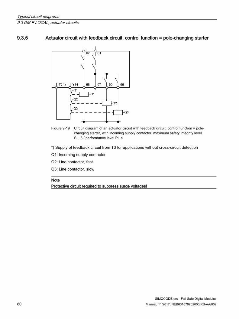
Typical circuit diagrams 9.3 DM-F LOCAL, actuator circuits
80 SIMOCODE pro - Fail-Safe Digital Modules
Manual, 11/2017, NEB631679702000/RS-AA/002
9.3.5 Actuator circuit with feedback circuit, control function = pole-changing starter
Figure 9-19 Circuit diagram of an actuator circuit with feedback circuit, control function = pole-changing starter, with incoming supply contactor, maximum safety integrity level SIL 3 / performance level PL e
*) Supply of feedback circuit from T3 for applications without cross-circuit detection
Q1: Incoming supply contactor
Q2: Line contactor, fast
Q3: Line contactor, slow
Note Protective circuit required to suppress surge voltages!

Typical circuit diagrams 9.3 DM-F LOCAL, actuator circuits
SIMOCODE pro - Fail-Safe Digital Modules Manual, 11/2017, NEB631679702000/RS-AA/002 81
Figure 9-20 Circuit diagram of an actuator circuit with feedback circuit, control function = pole-changing starter, without incoming supply contactor, maximum safety integrity level SIL 1 / performance level PL c
*) Supply of feedback circuit from T3 for applications without cross-circuit detection
Q2: Line contactor, fast
Q3: Line contactor, slow
Note Protective circuit required to suppress surge voltages!

Typical circuit diagrams 9.4 DM-F PROFIsafe, actuator circuits
82 SIMOCODE pro - Fail-Safe Digital Modules
Manual, 11/2017, NEB631679702000/RS-AA/002
9.4 DM-F PROFIsafe, actuator circuits
9.4.1 Connection examples for DM-F PROFIsafe, actuator circuit
Overview of DM-F PROFIsafe, actuator circuit This chapter contains examples showing the structure of the actuator circuit of the failsafe DM-F PROFIsafe digital module for various safety requirements (with or without an incoming supply contactor) and control functions (e.g. direct starter, reversing starter, star-delta starter).
The examples also illustrate the basic structure of the feedback circuit for monitoring the circuit state of the contactors.
9.4.2 Actuator circuit with feedback circuit, control function = direct starter
Figure 9-21 Circuit diagram of an actuator circuit with feedback circuit, control function = direct starter, with incoming supply contactor, maximum safety integrity level SIL 3 / performance level PL e
Q1: Incoming supply contactor
Q2: Motor contactor
Note Protective circuit required to suppress surge voltages!
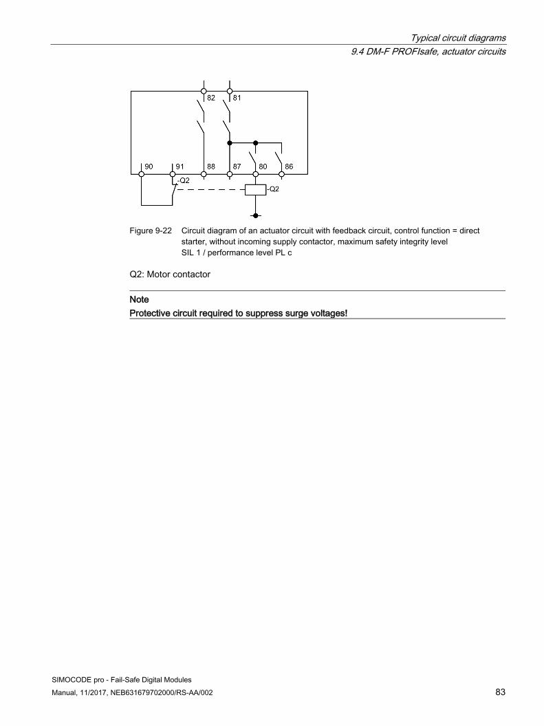
Typical circuit diagrams 9.4 DM-F PROFIsafe, actuator circuits
SIMOCODE pro - Fail-Safe Digital Modules Manual, 11/2017, NEB631679702000/RS-AA/002 83
Figure 9-22 Circuit diagram of an actuator circuit with feedback circuit, control function = direct starter, without incoming supply contactor, maximum safety integrity level SIL 1 / performance level PL c
Q2: Motor contactor
Note Protective circuit required to suppress surge voltages!
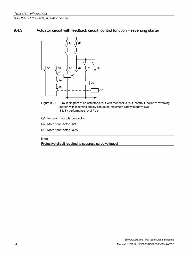
Typical circuit diagrams 9.4 DM-F PROFIsafe, actuator circuits
84 SIMOCODE pro - Fail-Safe Digital Modules
Manual, 11/2017, NEB631679702000/RS-AA/002
9.4.3 Actuator circuit with feedback circuit, control function = reversing starter
Figure 9-23 Circuit diagram of an actuator circuit with feedback circuit, control function = reversing starter, with incoming supply contactor, maximum safety integrity level SIL 3 / performance level PL e
Q1: Incoming supply contactor
Q2: Motor contactor CW
Q3: Motor contactor CCW
Note Protective circuit required to suppress surge voltages!

Typical circuit diagrams 9.4 DM-F PROFIsafe, actuator circuits
SIMOCODE pro - Fail-Safe Digital Modules Manual, 11/2017, NEB631679702000/RS-AA/002 85
Figure 9-24 Circuit diagram of an actuator circuit with feedback circuit, control function = reversing starter, without incoming supply contactor, maximum safety integrity level SIL 1 / performance level PL c
Q2: Motor contactor CW
Q3: Motor contactor CCW
Note Protective circuit required to suppress surge voltages!

Typical circuit diagrams 9.4 DM-F PROFIsafe, actuator circuits
86 SIMOCODE pro - Fail-Safe Digital Modules
Manual, 11/2017, NEB631679702000/RS-AA/002
9.4.4 Actuator circuit with feedback circuit, control function = star-delta starter
Figure 9-25 Circuit diagram of an actuator circuit with feedback circuit, control function = star-delta starter, with incoming supply contactor, maximum safety integrity level SIL 3 / performance level PL e
Q1: Incoming supply contactor
Q2: Line contactor
Q3: Delta contactor
Q4: Star contactor
Note Protective circuit required to suppress surge voltages!

Typical circuit diagrams 9.4 DM-F PROFIsafe, actuator circuits
SIMOCODE pro - Fail-Safe Digital Modules Manual, 11/2017, NEB631679702000/RS-AA/002 87
Figure 9-26 Circuit diagram of an actuator circuit with feedback circuit, control function = star-delta starter, without incoming supply contactor, maximum safety integrity level SIL 1 / performance level PL c
Q2: Line contactor
Q3: Delta contactor
Q4: Star contactor
Note Protective circuit required to suppress surge voltages!

Typical circuit diagrams 9.4 DM-F PROFIsafe, actuator circuits
88 SIMOCODE pro - Fail-Safe Digital Modules
Manual, 11/2017, NEB631679702000/RS-AA/002
9.4.5 Actuator circuit with feedback circuit, control function = Dahlander starter
Figure 9-27 Circuit diagram of an actuator circuit with feedback circuit, control function = Dahlander starter, with incoming supply contactor, maximum safety integrity level SIL 3 / performance level PL e
Q1: Incoming supply contactor
Q2: Line contactor, slow
Q3: Line contactor, fast
Q4: Star contactor
Note Protective circuit required to suppress surge voltages!

Typical circuit diagrams 9.4 DM-F PROFIsafe, actuator circuits
SIMOCODE pro - Fail-Safe Digital Modules Manual, 11/2017, NEB631679702000/RS-AA/002 89
Figure 9-28 Circuit diagram of an actuator circuit with feedback circuit, control function = Dahlander starter, without incoming supply contactor, maximum safety integrity level SIL 1 / performance level PL c
Q2: Line contactor, slow
Q3: Line contactor, fast
Q4: Star contactor
Note Protective circuit required to suppress surge voltages!

Typical circuit diagrams 9.4 DM-F PROFIsafe, actuator circuits
90 SIMOCODE pro - Fail-Safe Digital Modules
Manual, 11/2017, NEB631679702000/RS-AA/002
9.4.6 Actuator circuit with feedback circuit, control function = pole-changing starter
Figure 9-29 Circuit diagram of an actuator circuit with feedback circuit, control function = pole-changing starter, with incoming supply contactor, maximum safety integrity level SIL 3 / performance level PL e
Q1: Incoming supply contactor
Q2: Line contactor, fast
Q3: Line contactor, slow
Note Protective circuit required to suppress surge voltages!
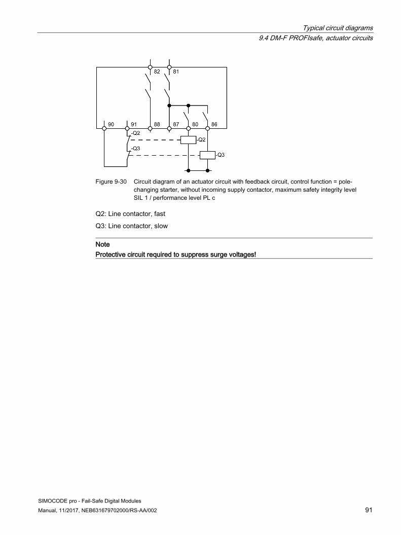
Typical circuit diagrams 9.4 DM-F PROFIsafe, actuator circuits
SIMOCODE pro - Fail-Safe Digital Modules Manual, 11/2017, NEB631679702000/RS-AA/002 91
Figure 9-30 Circuit diagram of an actuator circuit with feedback circuit, control function = pole-changing starter, without incoming supply contactor, maximum safety integrity level SIL 1 / performance level PL c
Q2: Line contactor, fast
Q3: Line contactor, slow
Note Protective circuit required to suppress surge voltages!

Typical circuit diagrams 9.4 DM-F PROFIsafe, actuator circuits
92 SIMOCODE pro - Fail-Safe Digital Modules
Manual, 11/2017, NEB631679702000/RS-AA/002

SIMOCODE pro - Fail-Safe Digital Modules Manual, 11/2017, NEB631679702000/RS-AA/002 93
Technical data 1010.1 Technical data of the DM-F Local and DM-F PROFIsafe fail-safe
digital modules
Technical data of the DM-F Local and DM-F PROFIsafe fail-safe digital modules
Table 10- 1 Technical data of the DM-F Local and DM-F PROFIsafe fail-safe digital modules
Mounting Snap-mounted onto 35 mm DIN rail or screw-mounted using additional push-in lugs
Enclosure width 45 mm System interfaces For connection to
• a basic unit• another expansion module• a current measuring module or current/voltage measuring module• the operator-control block
Permissible ambient temperature In operation -25 °C ... +60 °C During storage and transportation
-40 °C ... +80 °C
At installation altitude above sea level ≤ 2000 m ≤ 3000 m Max. +50 °C (no protective separation) ≤ 4000 m Max. +40 °C (no protective separation)
Degree of protection (according to IEC 60529)
IP 20
Shock resistance (sine pulse) 15 g / 11 ms Mounting position Any Frequencies 50/60 Hz ± 5 % EMC interference immunity in accordance with
IEC 60947-5-1, Edition 3.1:2009, SN 27095:2006, IEC 61326-3-1:2008, IEC 62061:2005
Rated control supply voltage Us according to DIN EN 61131-2
110 V - 240 V AC/DC, 50/60 Hz
24 V DC
Operating range • 24 V DC: 0.8 to 1.2xUs
• 110 V to 240 V AC/DC: 0.85 to 1.1xUs

Technical data 10.1 Technical data of the DM-F Local and DM-F PROFIsafe fail-safe digital modules
94 SIMOCODE pro - Fail-Safe Digital Modules
Manual, 11/2017, NEB631679702000/RS-AA/002
Mounting Snap-mounted onto 35 mm DIN rail or screw-mounted using additional push-in lugs
Power consumption DM-F Local: • 24 V DC: 3 W• 110 V to 240 V AC/DC: 9.5 VA/4.5 WDM-F PROFIsafe: • 24 V DC: 4 W• 110 V to 240 V AC/DC: 11.0 VA/5.5 W
Protective separation according to IEC 60947-1
Between relay enabling circuits/relay outputs and electronics
Rated insulation voltage Ui 300 V (at pollution degree 3) Rated impulse withstand voltage Uimp 4 kV Power loss ride-through time 110 V - 240 V AC/DC,
typ. 20 ms at 0.85 x Us, typ. 200 ms at 230 V
24 V DC, typ. 20 ms at 0.8 x Us
Relay outputs
• Quantity 2 monostable relay outputs
• Function • Common connection is internally disconnected in a fail-safe manner by a relayenabling circuit
• Normally open contact, freely assignable to the control functions
Electrical service life of relay outputs 0.1 million switching cycles (AC-15, 230 V/3 A) Relay enabling circuits
• Quantity 2 common switching-type, fail-safe relay enabling circuits
• Function Fail-safe normally open contacts
• Prescribed short-circuit protectionfor relay enabling circuits/relayoutputs
Fuse links operating class gL/gG 4 A (IEC 60947-5-1), separate for each relay enabling circuit
• Rated uninterrupted current ofrelay enabling circuits
5 A
• Rated switching capacity of relayenabling circuits
AC-15 DC-13
3 A/24 V AC 4 A/24 V DC
3 A/120 V AC 0.55 A/60 V DC
1.5 A/230 V AC 0.22 A/125 V DC 0.11 A/250 V DC
• Electrical service life of relayenabling circuits
0.1 million switching cycles (AC-15, 240 V/2 A)
• Switching rate of the relay enablingcircuits
2000/h

Technical data 10.1 Technical data of the DM-F Local and DM-F PROFIsafe fail-safe digital modules
SIMOCODE pro - Fail-Safe Digital Modules Manual, 11/2017, NEB631679702000/RS-AA/002 95
Mounting Snap-mounted onto 35 mm DIN rail or screw-mounted using additional push-in lugs
Connection Removable terminal block with screw connection
• Tightening torque TORQUE 7 lb.in ... 10.3 lb.in 0.8 Nm to 1.2 Nm
• Connection cross-sections Solid: 2 x 0.5 mm2 to 2.5 mm2 / 1 x 0.5 mm to 4 mm2 / 2 x AWG 20 to 14 / 1 x AWG 20 to 12 Finely stranded with end sleeve: 2 x 0.5 mm2 to 1.5 mm2 / 1 x 0.5 mm to 2.5 mm2 / 2 x AWG 20 to 16 / 1 x AWG 20 to 14
Engineering with • STEP 7 TIA Portal V12 SP1 and higher• STEP 7 V5.2 and higher (with installed SIMOCODE pro Integration in STEP 7
from SIMOCODE ES 2007 + SP2 and higher)
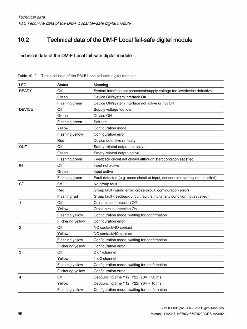
Technical data 10.2 Technical data of the DM-F Local fail-safe digital module
96 SIMOCODE pro - Fail-Safe Digital Modules
Manual, 11/2017, NEB631679702000/RS-AA/002
10.2 Technical data of the DM-F Local fail-safe digital module
Technical data of the DM-F Local fail-safe digital module
Table 10- 2 Technical data of the DM-F Local fail-safe digital modules
LED Status Meaning READY Off System interface not connected/supply voltage too low/device defective
Green Device ON/system interface OK Flashing green Device ON/system interface not active or not OK
DEVICE Off Supply voltage too low Green Device ON Flashing green Self-test Yellow Configuration mode Flashing yellow Configuration error Red Device defective or faulty
OUT Off Safety-related output not active Green Safety-related output active Flashing green Feedback circuit not closed although start condition satisfied
IN Off Input not active Green Input active Flashing green Fault detected (e.g. cross-circuit at input, sensor simultaneity not satisfied)
SF Off No group fault Red Group fault (wiring error, cross-circuit, configuration error) Flashing red Group fault (feedback circuit fault, simultaneity condition not satisfied)
1 Off Cross-circuit detection Off Yellow Cross-circuit detection On Flashing yellow Configuration mode, waiting for confirmation Flickering yellow Configuration error
2 Off NC contact/NO contact Yellow NC contact/NC contact Flashing yellow Configuration mode, waiting for confirmation Flickering yellow Configuration error
3 Off 2 x 1-channel Yellow 1 x 2-channel Flashing yellow Configuration mode, waiting for confirmation Flickering yellow Configuration error
4 Off Debouncing time Y12, Y22, Y34 ~ 50 ms Yellow Debouncing time Y12, Y22, Y34 ~ 10 ms Flashing yellow Configuration mode, waiting for confirmation

Technical data 10.2 Technical data of the DM-F Local fail-safe digital module
SIMOCODE pro - Fail-Safe Digital Modules Manual, 11/2017, NEB631679702000/RS-AA/002 97
LED Status Meaning Flickering yellow Configuration error
5 Off Sensor circuit, automatic start Yellow Sensor circuit, monitored start Flashing yellow Configuration mode, waiting for confirmation Flickering yellow Configuration error
6 Off Cascading input 1, automatic start Yellow Cascading input 1, monitored start Flashing yellow Configuration mode, waiting for confirmation Flickering yellow Configuration error
7 Off With start-up testing Yellow Without start-up testing Flashing yellow Configuration mode, waiting for confirmation Flickering yellow Configuration error
8 OFF Automatic starting after power failure Yellow No automatic starting after power failure Flashing yellow Configuration mode, waiting for confirmation Flickering yellow Configuration error
DIP switch Setting of the safety functions SET/RESET button • Application of parameters set via DIP switch
• Resetting of faults (also possible via "TEST/RESET" on basic unit)
Inputs with safety relay function
2 sensor inputs 24 V DC (Y12, Y22) • Supply via terminal T1 and T2 with cross-circuit detection or external supply (static +24 V DC)
without cross-circuit detection • Functions parameterizable via DIP switch
1 start signal input 24 V DC (Y33) • For monitored reconnection of the relay enabling circuits after a safety-related disconnection• Supply via terminal T1 with/without T3 (static +24 V DC) without cross-circuit detection
1 cascading input 24 V DC (1) • For use in connection with a higher-level safety relay• Supply via terminal T3 (static +24 V DC)
1 feedback circuit input 24 V DC (Y34) • For contactor monitoring of the motor and incoming supply contactors via series-connected
auxiliary switch normally-closed contacts• Supply via terminal T2 with/without T3 (static +24 V DC) without cross-circuit detection
Cable length between sensor and start signal inputs (single)
1500 m
Input characteristic Type 2 according to EN 61131-2
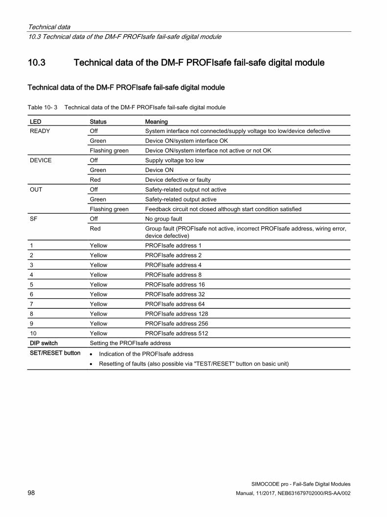
Technical data 10.3 Technical data of the DM-F PROFIsafe fail-safe digital module
98 SIMOCODE pro - Fail-Safe Digital Modules
Manual, 11/2017, NEB631679702000/RS-AA/002
10.3 Technical data of the DM-F PROFIsafe fail-safe digital module
Technical data of the DM-F PROFIsafe fail-safe digital module
Table 10- 3 Technical data of the DM-F PROFIsafe fail-safe digital module
LED Status Meaning READY Off System interface not connected/supply voltage too low/device defective
Green Device ON/system interface OK Flashing green Device ON/system interface not active or not OK
DEVICE Off Supply voltage too low Green Device ON Red Device defective or faulty
OUT Off Safety-related output not active Green Safety-related output active Flashing green Feedback circuit not closed although start condition satisfied
SF Off No group fault Red Group fault (PROFIsafe not active, incorrect PROFIsafe address, wiring error,
device defective) 1 Yellow PROFIsafe address 1 2 Yellow PROFIsafe address 2 3 Yellow PROFIsafe address 4 4 Yellow PROFIsafe address 8 5 Yellow PROFIsafe address 16 6 Yellow PROFIsafe address 32 7 Yellow PROFIsafe address 64 8 Yellow PROFIsafe address 128 9 Yellow PROFIsafe address 256 10 Yellow PROFIsafe address 512 DIP switch Setting the PROFIsafe address SET/RESET button • Indication of the PROFIsafe address
• Resetting of faults (also possible via "TEST/RESET" button on basic unit)

Technical data 10.4 Safety-specific technical data of the DM-F Local fail-safe digital module
SIMOCODE pro - Fail-Safe Digital Modules Manual, 11/2017, NEB631679702000/RS-AA/002 99
LED Status Meaning Inputs (binary) • 3 inputs 24 V DC (83, 85, 89)
• Supply via terminal 84 or external supply (static +24 V DC)• Common connected, electrically isolated inputs for acquiring process signals (e.g., local control
station, keyswitch, limit switch, etc.), freely assignable to control functions
Input with safety relay function
• 1 feedback circuit input 24 V DC (91/FBC)• For contactor monitoring of the motor and incoming supply contactors via series-connected
auxiliary switch normally-closed contacts• Supply via terminal 90/T
Cable length (single) 300 m Input characteristic Type 2 according to EN 61131-2
10.4 Safety-specific technical data of the DM-F Local fail-safe digital module
Safety-specific technical data of the DM-F Local fail-safe digital module
Table 10- 4 Values for 2-channel sensor evaluation
Values for 2-channel sensor evaluation Achievable Safety Integrity Level (SIL) in accordance with IEC 61508 Up to 3 SIL claim limit according to IEC EN 62061 3 Achievable performance level (PL) according to ISO 13849-1 Up to e Achievable category according to ISO 13849-1 Up to 4 PFHd with high demand rate according to EN 62061 1.0 x 10⁻⁸ 1/h PFDavg with low demand rate according to IEC 61508 2.0 x 10⁻⁵ 1/h Hardware fault tolerance HFT 1 Device type acc. to IEC 61508-2 B MTTFd high DCavg high

Technical data 10.4 Safety-specific technical data of the DM-F Local fail-safe digital module
100 SIMOCODE pro - Fail-Safe Digital Modules
Manual, 11/2017, NEB631679702000/RS-AA/002
Table 10- 5 Values for 1-channel sensor evaluation
Values for 1-channel sensor evaluation Achievable Safety Integrity Level (SIL) in accordance with IEC 61508 1 SIL claim limit according to IEC EN 62061 1 Achievable performance level (PL) according to ISO 13849-1 Up to d Achievable category according to ISO 13849-1 Up to 2 PFHd with high demand rate according to EN 62061 9.0 x 10⁻⁷ 1/h PFDavg with low demand rate according to IEC 61508 6.5 x 10⁻⁴ 1/h Hardware fault tolerance HFT 0 Device type acc. to IEC 61508-2 B MTTFd high DCavg Average
Table 10- 6 Further safety-specific technical data of the DM-F Local fail-safe digital module
Additional technical data T1 value (mission time) according to IEC 61508 20 years Stop category according to DIN EN 60204-1 0 Approval TÜV (IEC 61508, ISO 13849-1, NFPA79)

Technical data 10.5 Monitoring and response times of the DM-F Local fail-safe digital module
SIMOCODE pro - Fail-Safe Digital Modules Manual, 11/2017, NEB631679702000/RS-AA/002 101
10.5 Monitoring and response times of the DM-F Local fail-safe digital module
Monitoring and response times of the DM-F LOCAL fail-safe digital module
Table 10- 7 Monitoring and response times of the DM-F LOCAL fail-safe digital module
Monitoring and response times of the DM-F LOCAL fail-safe digital module Make time (with automatic start) • 50 ms (typ.)
• 100 ms (max.)
Make time (with automatic start) after power failure • 8.0 s (typ.)• 8.2 s (max.)
Make time (monitored start) • 50 ms (typ.)• 100 ms (max.)
Off-delay in case of power failure • DC: 60 ms (typ.)• AC: 200 ms (typ.)
Off-delay after opening of the safety circuits 50 ms (typ.) Recovery time after opening of the safety circuits 250 ms (typ.) Recovery time after power failure 8.0 s (typ.) Pulse duration • Sensor circuit: 30 ms (min.)
• Start input 0.2 s (min.)• Cascading input: 0.2 s (min.)

Technical data 10.6 Safety-specific technical data of the DM-F PROFIsafe fail-safe digital module
102 SIMOCODE pro - Fail-Safe Digital Modules
Manual, 11/2017, NEB631679702000/RS-AA/002
10.6 Safety-specific technical data of the DM-F PROFIsafe fail-safe digital module
Safety-specific technical data of the DM-F PROFIsafe fail-safe digital module
Table 10- 8 Safety-specific technical data of the DM-F PROFIsafe fail-safe digital module
PROFIsafe version V2 Achievable Safety Integrity Level (SIL) in accordance with IEC 61508 Up to 3 SIL claim limit according to IEC EN 62061 3 Achievable performance level (PL) according to ISO 13849-1 Up to e Achievable category according to ISO 13849-1 Up to 4 PFHd with high demand rate according to EN 62061 1.0 x 10⁻⁸ 1/h PFDavg with low demand rate according to IEC 61508 2.0 x 10⁻⁵ 1/h Hardware fault tolerance HFT 1 Device type acc. to IEC 61508-2 B Device type acc. to EN ISO 13849-1 4 MTTFd high DCavg high T1 value (mission time) according to IEC 61508 20 years Stop category according to DIN EN 60204-1 0 Approval TÜV (IEC 61508, ISO 13849-1, NFPA79)
10.7 Monitoring and response times of the DM-F PROFIsafe fail-safe digital module
Monitoring and response times of the DM-F PROFIsafe fail-safe digital module
Table 10- 9 Monitoring and response times of the DM-F PROFIsafe fail-safe digital module
PROFIsafe monitoring time (F_WD_Time) ≥ 250 ms Response time in error-free state/worst case delay time (Tmax/TWCDT) ≤ 150 ms Response time when error is present/one fault delay time (TOFDT) 200 ms

Technical data 10.8 Technical data in Siemens Industry Online Support
SIMOCODE pro - Fail-Safe Digital Modules Manual, 11/2017, NEB631679702000/RS-AA/002 103
10.8 Technical data in Siemens Industry Online Support
Technical data sheet You can also find the technical data of the product at Siemens Industry Online Support (https://support.industry.siemens.com/cs/ww/en/ps/).
1. Enter the full article number of the desired device in the "Product" field, and confirm withthe Enter key.
2. Click the "Technical data link.

Technical data 10.8 Technical data in Siemens Industry Online Support
104 SIMOCODE pro - Fail-Safe Digital Modules
Manual, 11/2017, NEB631679702000/RS-AA/002

SIMOCODE pro - Fail-Safe Digital Modules Manual, 11/2017, NEB631679702000/RS-AA/002 105
List of abbreviations AA.1 List of abbreviations
Table A- 1 Meaning of abbreviations
Abbreviation Meaning ANSI American National Standards Institute ATEX "Atmosphère explosible" according to ATEX Directive 94/9/EC AWG American Wire Gauge OPD Operator Panel with Display for SIMOCODE pro CPU Central Processing Unit DI Digital input DIP Dual In-line Package DM Digital Module DM-F Fail-safe digital module (DM-FL or DM-FP) DM-FL DM-F Local fail-safe digital module DM-FP DM-F PROFIsafe fail-safe digital module DO Digital output DP Distributed I/O EDD Electronic Device Description; for defining field device parameters, e.g., SIMATIC PDM EEx European Norm EXplosion-proof: Defines the protection classes for motors used in hazardous areas. Ex Explosion-proof F-CPU Fail-safe CPU (controller) F I/O Fail-safe I/O GG Basic unit GSD Device master data / device description file for PROFIBUS DP slaves IT Isolation-Terre (isolation ground) LCD Liquid Crystal Display LED Light Emitting Diode LSB Least Significant Bit MCC Motor Control Center MSB Most Significant Bit OM Object Manager for PROFIBUS DP slaves for integration into STEP 7 OSSD Part of the electro-sensitive protective equipment (ESPE) that is connected to the machine control
system and that switches to the OFF state if the sensor part is tripped during operation for the intended purpose.
PCS Process Control System PDM Process Device Manager PELV Protective Extra Low Voltage PFD Probability of dangerous failure of a safety function on demand

List of abbreviations A.1 List of abbreviations
106 SIMOCODE pro - Fail-Safe Digital Modules
Manual, 11/2017, NEB631679702000/RS-AA/002
Abbreviation Meaning PFDavg Average probability of dangerous failure of a safety function on demand PFHD Probability of dangerous failure per hour PL Performance Level PCS Process Control System ProdIS Product Information System PZ Pozidriv RTU Remote Terminal Unit SELV Safety Extra Low Voltage SF Group error SIL Safety Integrity Level PLC Programmable controller TIA Totally Integrated Automation TN Terre-Neutre (ground neutral) TT Terre-Terre (ground-ground) TOFDT Total one fault delay time (maximum response time when error is present) TWCDT Total worst case delay time (maximum response time in error-free state)

SIMOCODE pro - Fail-Safe Digital Modules Manual, 11/2017, NEB631679702000/RS-AA/002 107
Glossary
ATEX French abbreviation for "atmosphère explosible" (explosive atmosphere). ATEX is used as a synonym for the two European Community directives covering explosion protection, i.e. the ATEX product directive 94/9/EC and the ATEX workplace directive 1999/92/EC.
Cascade input Safe, 1-channel input of a safety relay, e.g. DM-F Local and DM-F PROFIsafe. Internally, this input is evaluated like a sensor signal. If no voltage is present, the safety relay trips the enabling circuits (outputs) in a safety-related way.
Central Processing Unit (CPU) Central processing unit of the programmable controller or the automation system comprised of an arithmetic logic unit (ALU), memory, and operating system. The user program is stored and processed in the CPU.
Circuit breaker In contrast to switch disconnectors, circuit breakers do not simply switch normal operational currents and low overload currents; they are also capable of disconnecting high overload currents and very high short-circuit currents. As overcurrent protective devices with a very high switching capacity (80 kA to 160 kA), they can switch equipment or plant components both during normal operation and – for a limited time period – in the event of a fault, e.g. a short-circuit. They additionally allow the equipment to be automatically restarted after the fault has been rectified.
Configurator Software program for designing customized products.
Contactor Electromagnetically operated low-voltage switch with only one position of rest; it cannot be manually operated. Contactors can energize, carry, and deenergize currents in a circuit under normal operating conditions, including operational overload. The contact system consists of main and auxiliary contacts (NC, NO). Depending on the size of the contactor, the main contacts can switch several hundred amps while the auxiliary contacts are only rated for control currents of a few amps.

Glossary
108 SIMOCODE pro - Fail-Safe Digital Modules
Manual, 11/2017, NEB631679702000/RS-AA/002
DIP switch Small switch used to make certain basic settings. The abbreviation stands for Dual In-line Package, in other words a device package with two parallel rows of electrical connecting pins.
Distributed In a distributed automation network, individual components are interconnected multiple times. This type of network ensures stable data transmission. Communication is still possible even if one or more connections are faulty.
DM-F Local and DM-F PROFIsafe digital modules The DM-F Local and DM-F PROFIsafe fail-safe digital modules are used as safety relays in emergency stop devices in accordance with EN 418 as well as in safety circuits in accordance with EN 60204 (11.98):
DM-F Local digital module: For applications that require local safety-related tripping with EMERGENCY OFF buttons.
DM-F PROFIsafe digital module: For applications that require decentralized safety-related tripping with EMERGENCY OFF buttons. A fail-safe SIMATIC controller adopts the logical connection between the EMERGENCY OFF button and the PROFIsafe fail-safe digital module (DM-F PROFIsafe).
Electromagnetic Compatibility (EMC) In electrical engineering, EMC (electromagnetic compatibility) describes the mutual interference that occurs between electrical devices which produce electromagnetic interference fields.
Emergency stop Shutdown in case of emergency according to EN 418 (ISO 13850). An action in an emergency that is intended to stop a process or motion that would result in a hazard.
Emergency stop control device Switching element ("emergency stop" mushroom pushbutton according to EN EN 418 (ISO 13850) or cable-operated switch (positive opening) according to EN 60204-1) that is operated in dangerous situations and stops the process, machine, or system. This element must have positive-opening contacts, and it should be easily accessible and tamper-proof so that it cannot be manipulated.
Emergency stop device Protective device that is operated in response to an emergency according to EN 418 (ISO 13850), EN 60204-1.

Glossary
SIMOCODE pro - Fail-Safe Digital Modules Manual, 11/2017, NEB631679702000/RS-AA/002 109
Enabling circuit An enabling circuit is used to generate a safety-related output signal. From an external viewpoint, enabling circuits act as NO contacts (however, in terms of functionality, safe opening is always the most important aspect). A single enabling circuit, that is internally redundantly configured in the safety relay (two channel) can be used for Category 3/4 according to EN 954-1 (EN ISO 13849-1:2006).
European Norm EXplosion-proof (EEx) Defines the protection classes for motors used in hazardous areas.
F_WD_Time Monitoring time in the fail-safe PROFIsafe option. A valid, current safety message frame must be received from the F-CPU within this monitoring time. Otherwise, the PROFIsafe option goes to the safe state.
Feedback circuit A feedback circuit is used to monitor controlled actuators (e.g. relays or contactors with positively driven contacts). The evaluation unit can only be activated if the feedback circuit is closed. Note: The NC contacts of the relays to be monitored are connected in series and integrated into the feedback circuit of the safety relay. If a contact in the enabling current path is welded, the safety relay can no longer be activated because the feedback circuit remains in the open position.
Field / field level The field or field level of an automation system contains the individual sensors and actuators, as opposed to the control level which is located above it in the hierarchy.
Fieldbus Industrial communication system that connects a large number of field devices (such as sensors, final control elements, and actuators) to a control circuit device.
I/O In automation engineering, the term "I/O" is used to refer to I/O devices. These include, for example, devices that are connected to centralized controls.
Low voltage All voltage levels used for the distribution of electricity that are within a range whose upper limit in AC systems is generally 1000 V.

Glossary
110 SIMOCODE pro - Fail-Safe Digital Modules
Manual, 11/2017, NEB631679702000/RS-AA/002
OEM (Original Equipment Manufacturer) Original Equipment Manufacturer: In its literal sense, a manufacturer that produces finished components or products in its own factories but does not retail them itself. However, in many industries the term OEM is meanwhile employed with a contradictory definition. In the engineering and automotive sectors, for instance, an OEM is a company that sells the finished product under its own brand name.
Overload relay An overload relay is an electronic component that protects an electrical load, such as a motor, quickly and reliably in the event of overload or phase failure.
PELV (Protective Extra Low Voltage) Protective measure against electric shock (formerly referred to as "protective extra low voltage with safe isolation").
In contrast to an SELV circuit, live parts and exposed conductive parts of the equipment may be grounded and connected to the protective conductor. Safe isolation means that the primary circuit of the transformer must be separated from the secondary circuit by double or reinforced insulation. PELV is used whenever operational reasons dictate that live conductors of the low voltage or bodies of the equipment must be grounded. This is the case, for instance, if equipotential bonding is necessary to prevent sparking in containers or hazardous areas. However, owing to the chassis ground, dangerous leakage currents can flow through the body regardless of the low voltage if a fault occurs in the higher-level power system.
Performance Level (PL) According to EN ISO 13849-1, this is the average probability of a hazardous failure per hour. Five performance levels are specified (a to e) with defined ranges of the probability of a dangerous failure per hour.
PL "e" corresponds to SIL 3 and is specified as the highest level.
Process Automation (PA) Automation of continuous production processes. For instance, it controls production processes in the chemical industry or in water supply systems.
Product lifecycle Term referring to the anticipated, or historically recorded, development of sales for defined products during the period for which they are offered in the market. The product lifecycle describes the five ideal market and product phases, namely the launch phase (1), growth phase (2), maturity phase (3), saturation phase (4), and degeneration phase (5).

Glossary
SIMOCODE pro - Fail-Safe Digital Modules Manual, 11/2017, NEB631679702000/RS-AA/002 111
PROFIBUS Process Fieldbus, a European process and fieldbus standard defined in the PROFIBUS standard (EN 50 170, Volume 2, PROFIBUS). It specifies the functional, electrical and mechanical characteristics of a bit-serial fieldbus system.
PROFIBUS is a bus system that networks PROFIBUS-compatible automation systems and field devices at the cell and field level. PROFIBUS is available with the DP (= Distributed Peripherals), FMS (= Fieldbus Message Specification), PA (= Process Automation), or TF (= Technological Functions) protocol.
PROFINET Standard for industrial Ethernet in automation systems.
PROFIsafe The PROFIBUS safety profile specifies communication between fail-safe I/O devices and fail-safe controllers. It is based on the standards for safety-related applications as well as on the experience of PLC users and manufacturers who are members of PROFIBUS International (PI). The PROFIBUS safety profile has TÜV and BIA (Institute for Occupational Safety and Health of the German Social Accident Insurance) certification.
Programmable controller (PLC) Electronic module used for open-loop and closed-loop control tasks in an automation system. It is basically a control unit with specialized input and output interfaces for sensors and actuators. A PLC can consequently control, monitor, and influence processes.
Programming device (PG) A compact and transportable PC, suitable for industrial purposes. Its distinguishing feature is the special hardware and software for SIMATIC programmable controllers.
Residual current operated circuit breaker (RCCB) Protective device in a power supply system. It disconnects the connected and monitored circuit from the remainder of the power supply system if current is flowing in the wrong direction, for instance through a person's body.
Safety Extra Low Voltage (SELV) Low electric voltage (formerly "protective extra low voltage") up to 50 V AC or 120 V DC, that offers significant protection against electric shock due to its low value and insulation.
Devices that are operated with SELV and do not generate high voltages are categorized as Class III according to DIN EN 61140 (VDE 0140-1).
Glossary
112 SIMOCODE pro - Fail-Safe Digital Modules
Manual, 11/2017, NEB631679702000/RS-AA/002
Safety Integrity Level (SIL) Measure defined in IEC 61508, for the safety-related performance of an electrical or electronic control device.
The IEC standard defines four SIL levels SIL1 to SIL 4, which are defined as the safety implementations of electrical and electronic equipment. The SIL value describes the specified safety function in the event of a fault.
SIL (Safety Integrity Level) Measure defined in IEC 61508, for the safety-related performance of an electrical or electronic control device.
The IEC standard defines four SIL levels SIL1 to SIL4, which are defined as the safety implementations of electrical and electronic equipment. The SIL value describes the specified safety function in the event of a fault.
SIMATIC Name of products and systems for industrial automation from Siemens AG.
SIMATIC PDM You can also configure SIMOCODE pro using the SIMATIC PDM (Process Device Manager) software. The following options exist:
● SIMATIC PDM as a standalone program
● PDM integrated in STEP 7
SIMOCODE ES Standard parameterization software for SIMOCODE pro, which can be run on a PC / PG under Windows XP or Windows 7 Ultimate and Professional.
SIMOCODE pro S7 slave The SIMOCODE pro S7 slave is a special slave with the following characteristics:
● It supports the S7 model (diagnostic interrupts, process interrupts)
● It can be parameterized
Slave PROFIBUS DP is based on a master-slave architecture. Telegrams are sent by the master to the addressed station (slave) and responded to by the slave.
Speed Number of revolutions of a motor shaft.

Glossary
SIMOCODE pro - Fail-Safe Digital Modules Manual, 11/2017, NEB631679702000/RS-AA/002 113
STEP 7 Latest version of the TIA-capable programming software in the SIMATIC S7 PLC family and successor to STEP 5.
Terminal block Insulating part comprised of one or more terminals, insulated from one another, for mounting on a strip.
Torque A variable that produces a rotary motion. In an electric motor, the torque is transmitted by the rotating motor shaft. Torque, measured in Newton meters (Nm), is the product of moment arm multiplied by force. This "lever" multiplied by the speed determines the motor rating.
Totally Integrated Automation (TIA) Hierarchically structured automation and process control system, reaching from the plant control and production management levels down to the field level.
Totally Integrated Power (TIP) Integrated concept developed by Siemens Industry for electrical power distribution to and in non-residential and industrial buildings. It extends through all phases of a power distribution project – from the initial investment decision through planning to installation and operation.
WinCC SIMATIC WinCC is a process visualization or SCADA system (PC based HMI system) for visualizing and controlling processes, production flows, machines and equipment in all industries – from simple single-user systems through to distributed multi-user systems with redundant servers and remote solutions with web clients. At the same time, WinCC acts as an information hub for company-wide vertical integration (process visualization and platform for IT and business integration).
WinCC flexible SIMATIC WinCC flexible is designed for applications directly at the machine, ranging from PC-based HMI solutions for single-user systems featuring WinCC flexible Runtime through to SIMATIC HMI operator panels. The WinCC flexible family also includes integrated and scalable configuration tools for configuring WinCC flexible Runtime for PCs as well as SIMATIC HMI devices.

Glossary
114 SIMOCODE pro - Fail-Safe Digital Modules
Manual, 11/2017, NEB631679702000/RS-AA/002

SIMOCODE pro - Fail-Safe Digital Modules Manual, 11/2017, NEB631679702000/RS-AA/002 115
Index
A Abbreviations, 105 Achievable category according to ISO 13849-1, 99, 100, 102 Achievable performance level (PL) according to ISO 13849-1, 99, 100, 102 Achievable Safety Integrity Level (SIL) in accordance with IEC 61508, 99, 100, 102 Actuator circuit, 59 Actuator circuit with feedback circuit, 60 Actuators, 17, 18 Address assignment, 47 ANSI, 105 Application / safety relay safety category, 42 Applications of DM-F Local, 16 Applications of DM-F PROFIsafe, 16 Approval, 100, 102 Assignment of the PROFIsafe address, 48 ATEX, 105 AWG, 105
C Cable length (single), 97, 99 Configuring SIMOCODE pro V with DM-F PROFIsafe, 50 Connecting, 27 Connection, 95 Connection cross-sections, 95 CPU, 105 Cross-circuit fault, 45 Current notes on operational safety, 12
D DCavg, 99, 100, 102 Deactivation, 39 Defining the DM-F parameters according to the sensor circuitry, 57 Degree of protection (according to IEC 60529), 93 Device type acc. to EN ISO 13849-1, 102 Device type acc. to IEC 61508-2, 99, 100, 102 Device versions, 16 DI, 105 DIP, 105
DIP switch, 97, 98 DIP switch settings, DM-F Local, 41 Displaying the configuration, 44 Displaying the set PROFIsafe address and the DIP switch setting with SIMOCODE ES (SIMOCODE ES 2007) or SIMOCODE ES (TIA-Portal), 50 DM, 105 DM-F, 105 DM-F LOCAL - Actual and preset configuration different, 45 DM-F LOCAL configuration mode, 45 DM-F Local digital module, 15 DM-F LOCAL OK, 45 DM-F LOCAL Waiting for start-up test, 45 DM-F Local, actuator circuit, 72 DM-F Local, sensor circuit, 63 DM-F PROFIsafe active, 54 DM-F PROFIsafe digital module, 15 DM-F PROFIsafe, actuator circuit, 82 DM-F safety-related tripping, 45, 54 DM-FL, 105 DM-FP, 105 DO, 105 DP, 105
E EDD, 105 EEx, 105 Electrical service life of relay enabling circuits, 94 Electrical service life of relay outputs, 94 EMC interference immunity, 93 Enabling circuit closed, 45, 54 Enclosure width, 93 Engineering software, 95 Evaluation, 39 Ex, 105
F F I/O, 105 Factory setting, 40 Fail-safe controller
DM-F PROFIsafe, 15 F-CPU, 15
F-CPU, 105

Index
116 SIMOCODE pro - Fail-Safe Digital Modules
Manual, 11/2017, NEB631679702000/RS-AA/002
Feedback circuit, 45, 54, 59 F-monitoring time, 52 Frequencies, 93 Function of the cascade input (terminal 1), 42 Further information about F-I/O access, 47 Further safety-specific technical data of the DM-F Local fail-safe digital module, 100
G Generating circuit diagrams, 60 GG, 105 GSD, 105
H Hardware fault tolerance HFT, 99, 100, 102
I Incorrect PROFIsafe address or incorrect PROFIsafe parameters, 54 Input characteristic, 97, 99 Input with safety relay function, 99 Inputs (binary), 99 Inputs with safety relay function, 97 Integrating SIMOCODE pro V into S7 Distributed Safety with DM-F PROFIsafe, 53 Integrating SIMOCODE pro V into S7 F/H Systems with DM-F PROFIsafe, 53 Integrating SIMOCODE pro V into STEP 7 Safety (TIA Portal) with DM-F PROFIsafe, 53 Integrating the DM-F PROFIsafe into the fail-safe automation system using PROFIBUS / PROFIsafe or PROFINET / PROFIsafe, 47 IT, 105
L LCD, 105 LED, 105 LEDs on DM-F Local, 31 LEDs on DM-F PROFIsafe, 37 Liability disclaimer, 13 LSB, 105
M Main circuit, 60 Make time (monitored start), 101
Make time (with automatic start), 101 Make time (with automatic start) after power failure, 101 Manual Collection, 11 MCC, 105 Messages on the fail-safe DM-F Local digital module, 45 Messages on the fail-safe DM-F PROFIsafe digital module, 54 Monitoring – Interval for mandatory testing, 54 Monitoring - Interval to mandatory testing - Test requirement, 45 Monitoring and response times of the DM-F LOCAL fail-safe digital module, 101 Monitoring and response times of the DM-F PROFIsafe fail-safe digital module, 102 Monitoring the feedback circuit in the fail-safe controller, 54 Mounting, 93 Mounting on a standard rail, 24 Mounting position, 93 MSB, 105 MTTFd, 99, 100, 102
N Newsletter, 12 No module voltage, 45, 54 Non-safety-related function, 18
O Off-delay after opening of the safety circuits, 101 Off-delay in case of power failure, 101 OM, 105 OPD, 105 Operating range, 93 Option package, 50 Order nos., 16 Orientation aids, 11 OSSD, 105
P PCS, 105, 106 PDM, 105 PELV, 105 Performance Level, 15 Permissible ambient temperature, 93 PFD, 105 PFDavg, 106

Index
SIMOCODE pro - Fail-Safe Digital Modules Manual, 11/2017, NEB631679702000/RS-AA/002 117
PFDavg with low demand rate according to IEC 61508, 99, 100, 102 PFHD, 106 PFHd with high demand rate according to EN 62061, 99, 100, 102 PL, 106 PLC, 106 Power consumption, 94 Power loss ride-through time, 94 ProdIS, 106 PROFIsafe address, 48 PROFIsafe monitoring time (F_WD_Time), 102 Pulse duration, 101 PZ, 106
R Rated control supply voltage Us according to DIN EN 61131-2, 93 Rated impulse withstand voltage Uimp, 94 Rated insulating voltage Ui, 94 Rated switching capacity of relay enabling circuits, 94 Rated uninterrupted current of relay enabling circuits, 94 Recovery time after opening of the safety circuits, 101 Recovery time after power failure, 101 Relay enabling circuits, 94 Relay outputs, 94 Replacing a DM-F Local or a DM-F PROFIsafe, 55 RESET in the event of a fault, 44 Response time in error-free state/worst case delay time (Tmax/TWCDT), 102 Response time when error is present/one fault delay time (TOFDT), 102 RTU, 106
S Safe isolation according to IEC 60947-1, 94 Safety chain, 39 Safety Integrity Level, 15 Safety notices for mounting and wiring, 23 Safety-related function, 17, 20
Actuators, 17 Sensors, 17
Safety-related tripping, 15 Safety-specific technical data of the DM-F Local fail-safe digital module, 99 Safety-specific technical data of the DM-F PROFIsafe fail-safe digital module, 102
Safety-specific values for 1-channel sensor evaluation, 100 Safety-specific values for 2-channel sensor evaluation, 99 Scope, 11 Screw mounting, 26 SELV, 106 Sensing, 39 Sensor circuit, 59 Sensor circuit (only in conjunction with DM-F Local), 60 Sensors, 17 Service and support, 10 SET/RESET button, 97, 98 Setting of the F-monitoring time, 52 Setting the configuration, 43 SF, 106 Shock resistance (sine pulse), 93 Short-circuit protection for relay enabling circuits/relay outputs, 94 SIL, 106 SIL claim limit according to IEC EN 62061, 99, 100, 102 Simultaneity, 45 Standard function (non-safety-related), 20 Stop category according to DIN EN 60204-1, 100, 102 Storing the set PROFIsafe address, 49 Switching rate of the relay enabling circuits, 94 System interfaces, 93
T T1 value (mission time) according to IEC 61508, 100, 102 Target group, 9 Technical Assistance, 14 Technical data of the DM-F Local and DM-F PROFIsafe fail-safe digital modules, 93 Technical data of the DM-F Local fail-safe digital module, 96 Technical data of the DM-F PROFIsafe fail-safe digital module, 98 TIA, 106 Tightening torque, 95 TN, 106 TOFDT, 106 TT, 106 TWCDT, 106 Typical circuit diagram of a reversing starter with safety-related tripping via an emergency stop control device, maximum level SIL 3 or PL e, 61

Index
118 SIMOCODE pro - Fail-Safe Digital Modules
Manual, 11/2017, NEB631679702000/RS-AA/002
Typical circuit diagram of a reversing starter with safety-related tripping via PROFIBUS / PROFIsafe or PROFINET / PROFIsafe, maximum level SIL 3 or PL e, 62
V Versions, 18, 20
W Wiring, 45, 54