manual forced action mixers - machinery.fi · motto: maximum power — minimum load. a powerful...
TRANSCRIPT

MANUALFORCED ACTION MIXERS GB-13.06.17
MODEL 40LMixing capacity: 40 litres
MODEL 80LMixing capacity: 80 litres
MODEL 100LMixing capacity: 100 litres
MODEL 120LMixing capacity: 120 litres
MODEL 200LMixing capacity: 200 litres
MODEL 300LMixing capacity: 300 litres
THE RIGHT MODEL ANDSIZE DO MATTER.FOR ANY JOB BIG OR SMALLSOROTO OFFERS THE RIGHT SIZE MODEL.
English
GB / 2 3 / GB
TABLE OF CONTENTS
SoRoTo 40L, 80L, 100L, 120L .....................................p. 3 Application .....................................................................p. 3 Before use .......................................................................p. 3 Before connecting the power supply ................p 3 Operating the SoRoTo forced action mixer ...p. 3 Cleaning / maintenance ...........................................p. 4 Transport .........................................................................p. 4 Safety ................................................................................p. 4 Technical data ...............................................................p. 6 Contact details .............................................................p. 6 Special features/spare parts ..................................p. 7 Spare part list – 40 L .................................................p. 8 Spare part list – 80 L .................................................p. 10 Spare part list – 100 L ...............................................p. 12 Spare part list – 120 L ................................................p. 14
SoRoTo 200L, 300L........................................................p. 16 Application .....................................................................p. 16 Before use .......................................................................p. 16 Before connecting the power supply ................p 16 Operating the SoRoTo forced action mixer ...p. 16 Cleaning / maintenance ...........................................p. 17 Transport .........................................................................p. 18 Safety ................................................................................p. 19 Technical data ...............................................................p. 19 Contact details .............................................................p. 19 Spare part list – 200 L ..............................................p. 20 Spare part list – 300 L ..............................................p. 22
EC Declaration of Conformity ....................................p. 24
MANUAL APPLIES TOSoRoTo 40L, 80L, 100L, 120L
APPLICATIONThe SoRoTo Forced Action Mixers are ideal for mixing all kinds of materi-als used in the building industry, as well as for tasks where high demands are imposed on quality of the mix.
When mixing materials containing aggregates, we recommend using the SoRoTo Mixer arms set with rubber blades. (NOTE: The SoRoTo Forced Action Mixer 40L is not suited for mixing materials containing aggre-gates).
When using mixer arms equipped with steel blades to mix materials containing aggregates, the mixer arms may work their way upwards and eventually stop turning.
BEFORE USE Before starting the mixer, the telescopic legs must be positioned for the right height for draining into a bucket or wheelbarrow. The easiest way for adjusting the legs is to lay down the mixer, so it rests on all four wheels. The legs are released and locked with the fitted lock splits/bolts.
BEFORE CONNECTING THE POWER SUPPLYBefore the power is connected, the mixer arms must be set in place, and the lid must be closed. The safety grid in front of the mixer gate must be attached at all times.
For own safety please always follow the instructions listed above before use.
OPERATING THE SOROTO FORCED ACTION MIXERClose the lid and lock it into place using the rubber strap. Start the mixer by pressing the green START button on the protective motor switch. Pour the required material into the drum and add liquid.
The protective motor switch has a zero voltage releaser. In case of power failure, the mixer must be restarted. For safety reasons, the mixer will not start if the lid is open.

GB / 4 5 / GB
NOTENever put your hand or any object into the machine when the power is connected.
When the material has reached the desired consistency and the mix-ing motion is finished, the mixing drum is emptied by opening the mixer gate. The drum should be emptied right after mixing. Please observe that the material may set in the mixing drum, if left too long.
NOTEThe safety grid should be in front of the output gate at all times. If the machine is jammed, e.g. by larger stones, ensure that the plug is discon-nected from the protective motor switch, before removing the obstruc-tion. Do not put your fingers or any object through the mixer gate.
CLEANING / MAINTENANCEBefore cleaning the mixer, the plug must be removed from the socket.Open the lid and lift the mixing blades off the axle. The mixer arms are easily removed without using tools.
Firstly wash the mixer arms and the entire mixing drum using water.When cleaning has ended, place the mixer arms onto the axle and close the lid.
TRANSPORTDuring transport of the SoRoTo Forced Action Mixer it is recommended that the mixer be placed on the four wheels, and the lid is closed and locked with the rubber strap.
SAFETYWhen using an extension cable, please observe of the following,
• Never use a longer cable than necessary.• Always use a cable with a minimum dimension of 1 mm2.• Never use the cable when it is rolled up. Always roll it out completely.
When mixing materials that emit unpleasant or dangerous vapours and/or dust, a dust controller is recommended.
SMALL LOADING WHEELSand the use of customized lowered nuts mean you can easily load the ma-chine onto the truck. Even the biggest machines are easy to handle
OPTIONALDUST CONTROLLERhelps avoiding dangerous dust discomfort - without losing the opportunity to keep an eye on the mixture, as you do with a closed forced action mixer
GEAR MOTORselected under the motto: maximum power — minimum load. A powerful motor which, on the other hand, has the lowest possible ampere consumption, so the strain on the power grid and the environ-ment is minimized
SAFETY GRIDin front of the
discharge chute, together with the safety switch, en-sure that you do not risk harming
yourself in the working machine
SPARE POWER OUTLETModels 200L and 300L
are equipped with a spare power outlet for work
lighting, industrialvacuumcleaner,
belt conveyor or the like
BRACKETis mounted on every machine
for holding a brick trowel
BUCKET STAND
All 240V machines are
equipped with a robust bucket stand
for a masonry bucket
TELESCOPIC LEGSensure the right working height
WHEELSthe mixer is easily moved from one place to another on the construction site without any use of a vehicle
OPTIONALTURBO ARMCan be mounted on the 300L mixer(e.g. for masonry mortar)
DISTINCTIVE SOROTOMIXER ARMSare removed without toolsfacilitates cleaning and replacement. Also avail-able with rubber blades for mixes containingaggregates
RUBBER STRAPThe machines are
equipped with a rubber strap that ensure that the
grid lid does not openduring use or transport
the original and some extra

GB / 6 7 / GB
TECHNICAL DATAModel 40L/30Motor: 240V/110V - 0.75 kW – 50 HzW/L/H: 60*60*85 cmMixing capacity: 40 L.Weight: 45 kg (empty).LAeq< 75dB(A) with mortar.
Model 80L/30Motor: 240V/110V - 1.1 kW – 50 HzW/L/H: 60*75*106 cmMixing capacity: 80 L.Weight: 65 kg (empty).LAeq< 75dB(A) with mortar.
Model 100L/30Motor: 240V/110V - 1.1 kW – 50 HzW/L/H: 68*80*106 cmMixing capacity: 100 L.Weight: 75 kg (empty).LAeq< 75dB(A) with mortar.
Model 120L/30Motor: 240V/110V – 1.1 kW – 50 HzW/L/H: 72*95*118 cmMixing capacity: 120 L.Weight: 90 kg (empty).LAeq< 75dB(A) with mortar.
TECHNICAL SUPPORT / WAREHOUSEFabriksparken 11DK-2600 GlostrupTel. +45 3672 [email protected]
SALES / ADMINFabriksparken 13DK-2600 GlostrupTel. +45 3672 [email protected]
INCLUDINGMixer arms with steel blades and cross joint
INCLUDING Bracket for holding a brick trowel
OPTIONALDust controller for betterOSH*
INCLUDINGSmall loading wheelsfor easy on-/unloading
INCLUDINGTelescopic legs for setting the right working hight
OPTIONALRubber blades for mixes containing aggregates
* Occupational Safety and Health

GB / 8 9 / GB
Pos.No. Description Spare Part No. 2 Grid lid (hinge 100 mm) .........................................................40.002 3 Mixer drum incl. mixer gate, complete set ............................40.003 3 R Rubber strap for grid lid .........................................................40.003R 4 Frame, complete w/wheels etc. ............................................40.004 4 A Frame, “Body” - excl. wheels and telescopic legs ................40.004A 5 Loading wheel (1 pc.), 80 mm, excl. bolt ..............................40.005 5 B Bolt (1 pc.) for 80 mm loading wheel ....................................40.005B 6 Wheel (1 pc.), 300 mm, excl. bolt .........................................40.006 6 B Bolt (1 pc.) for 300 mm wheel ...............................................40.006B 6 W Washer (1 pc.) for 300 mm wheel .........................................40.006W 7 Mixer gate incl. bolt etc ..........................................................40.007 8 Switch 9.5 Amp. w/thermal circuit breaker ..........................40.008 8 E Safety switch - by the grid lid .................................................40.008E 8 K Cassette for safety switch, complete .....................................40.008K 8 K1 Piece for safety switch, bended metal part ..........................40.008K1 8 K2 Piece for safety switch, twisted metal part. ..........................40.008K2 8 K3 Piece for safety switch, rubber part ......................................40.008K3 9 Mixer arm (1 pc.), Side (long).................................................40.009 9 A Mixer arm (1 pc.), Side (short) ...............................................40.009A 10 Mixer arm (1 pc.), Side-base ..................................................40.010 11 Mixer arm (1 pc.), Rake ..........................................................40.011 12 Drive shaft, complete .............................................................40.012 12 A Spring pins, complete set of 12 incl. a jig .............................40.012A 13 Gear motor 0.75 kW, 1400/30 RPM., 230 V .......................40.013 13 G - Gear only ...............................................................................40.013G 13 M - Motor only .............................................................................40.013M 14 Starting capacitor 125 µf .......................................................40.014 15 Operating capacitor 25 µf ......................................................40.015 16 Phase capacitor 20 µf ............................................................40.016 17 B Telescopic legs, rear ...............................................................40.017B 17 L Teleskopic leg (1 pc.), front - left side ...................................40.017L 17 R Teleskopic leg (1 pc.), front - right side .................................40.017R 17 SB Bolt and nut (1 pair) for telescopic leg (1 pc.) ....................40.017SB 19 Safety grid by the mixer gate .................................................40.019 22 Mixer arms, 4 pcs., complete set ..........................................40.022 22 A Mixer arms, 4 pcs., wo/cross joint ........................................40.022A 30 Discharge chute (incl. nuts) ...................................................40.030 44 Cross joint for mixer arms, steel ............................................40.044
3R
2
5
37
7
8
4
9
9A
6
6
5
6B 5B
10
11
12
44
8E
8E
8K
22
19
15
1630
14
13
13M
17R 17L
13G
22A
17B
6W
8K3
8K2
8K1
12A
Spare Part List - 40 L, 230V
DE-07.03.17
GB-15.03.17
Spare Part List for the 40 L mixers, 110V, is available online atwww.soroto.dk/en

GB / 10 11 / GB
Pos. No. Description Art. No. 1 * Dust liminator ......................................................................... 80.001DL 2 Grid lid (hinge 100 mm) ......................................................... 80.002 3 Mixer drum incl. mixer gate, complete set ............................ 80.003 3 R Rubber strap - for grid lid ....................................................... 80.003R 4 Frame, complete w/wheels etc. ............................................ 80.004 4 B Bucket stand ........................................................................... 80.004B 4 F Frame, front part (U-shape) ................................................... 80.004F 4 L Frame, left side part ............................................................... 80.004L 4 R Frame, right side part ............................................................. 80.004R 4 T Frame, top/rear part .............................................................. 80.004T 5 Loading wheel (1 pc), 80 mm, excl. bolt ............................... 80.005 5 B Bolt (1 pc.) for 80 mm loading wheel .................................... 80.005B 6 Wheel (1 pc.), 300 mm, excl. bolt ......................................... 80.006 6 B Bolt (1 pc.) for 300 mm wheel ............................................... 80.006B 6 W Washer (1 pc.) for 300 mm wheel ......................................... 80.006W 7 Mixer gate incl. bolt etc. ......................................................... 80.007 8 Switch 9.5 Amp. w/thermal circuit breaker .......................... 80.008 8 E Safety switch - by the grid lid ................................................. 80.008E 8 K Cassette for safety switch, complete ..................................... 80.008K 8 K1 Piece for safety switch, bended metal part .......................... 80.008K1 8 K2 Piece for safety switch, twisted metal part. .......................... 80.008K2 8 K3 Piece for safety switch, rubber part ...................................... 80.008K3 9 Mixer arm (1 pc.), Side ........................................................... 80.009 10 Mixer arm (1 pc.), Side-base .................................................. 80.010 11 Mixer arm (1 pc.), Rake .......................................................... 80.011 12 Drive shaft, complete ............................................................. 80.012 12 A Spring pins, complete set of 12 pins incl. a jig ..................... 80.012A 13 Gear motor 1.1 kW, 1400/30 RPM, 230 V........................... 80.013 13 G - Gear only ............................................................................... 80.013G 13 M - Motor only ............................................................................. 80.013M 14 Starting capacitor 125 µf ....................................................... 80.014 15 Operating capacitor 25 µf ...................................................... 80.015 16 Phase capacitor 20 µf ............................................................ 80.016 17 B Telescopic legs, rear ............................................................... 80.017B 17 L Telescopic leg, front - left side ............................................... 80.017L 17 R Telescopic leg, front - right side ............................................. 80.017R 17 SB Bolt and nut (1 pair) for telescopic leg (1 pc.) .................... 80.017SB 19 Safety grid - by the mixer gate ............................................... 80.019 20 * Mixer arms w/rubber, 3 pcs., complete set .......................... 80.020 20 A Mixer arms w/rubber, 3 pcs., wo/cross joint ........................ 80.020A 48 Mixer arm w/rubber, Rake ..................................................... 80.048 49 Mixer arm w/rubber, Side-base ............................................. 80.049 50 Mixer arm w/rubber, Side ...................................................... 80.050 21 Rubber parts (replacement set, complete) ........................... 80.021 21 A Rubber parts (replacement set, blades only) ....................... 80.021A 21 B Rubber parts (replacement set, cross joint only) ................. 80.021B 22 Mixer arms, set of 4 pcs., complete ...................................... 80.022 22 A Mixer arms, set of 4 pcs., wo/cross joint .............................. 80.022A 30 Discharge chute (incl. nuts) ................................................... 80.030 44 Cross joint for mixer arms, steel ............................................ 80.044 47 Cross joint for mixer arms, rubber ......................................... 80.047 51 Bracket for mixer blade, rubber, Rake .................................. 80.051 52 Bracket for mixer blade, rubber, Side-base .......................... 80.052 53 Bracket for mixer blade, rubber, Side.................................... 80.053
* OP
TION
AL /
AD
DIT
OIN
AL E
QUIP
MEN
T
3
4T
4F4L 4R
4
6
830
20
22
9
11
10
944
19
3R8E
4B
4B
56
5B
1
2
47
8K1
21A
21B
6B
17SB
8K3
8K2
6W
17L17B
17R
22A
13G
12A
13M
21
51
48
49 50
52
53
13
12
8E
8K
7
7
15
1614
Spare Part List - 80 L, 230VGB-15.03.17
Spare Part List for the 80 L mixers, 110V, is available online atwww.soroto.dk/en

GB / 12 13 / GB
Pos. No. Description Art. No. 1 * Dust liminator ......................................................................... 100.001DL 2 Grid lid (hinge 100 mm) ......................................................... 100.002 3 Mixer drum incl. mixer gate, complete set ............................ 100.003 3 R Rubber strap - for grid lid ....................................................... 100.003R 4 Frame, complete w/wheels etc. ............................................ 100.004 4 B Bucket stand ........................................................................... 100.004B 4 F Frame, front part (U-shape) ................................................... 100.004F 4 L Frame, left side part ............................................................... 100.004L 4 R Frame, right side part ............................................................. 100.004R 4 T Frame, top/rear part .............................................................. 100.004T 5 Loading wheel (1 pc), 80 mm, excl. bolt ............................... 100.005 5 B Bolt (1 pc.) for 80 mm loading wheel .................................... 100.005B 6 Wheel (1 pc.), 300 mm, excl. bolt ......................................... 100.006 6 B Bolt (1 pc.) for 300 mm wheel ............................................... 100.006B 6 W Washer (1 pc.) for 300 mm wheel ......................................... 100.006W 7 Mixer gate incl. bolt etc. ......................................................... 100.007 8 Switch 16 Amp. w/thermal circuit breaker ........................... 100.008 8 E Safety switch - by the grid lid ................................................. 100.008E 8 K Cassette for safety switch, complete ..................................... 100.008K 8 K1 Piece for safety switch, bended metal part .......................... 100.008K1 8 K2 Piece for safety switch, twisted metal part. .......................... 100.008K2 8 K3 Piece for safety switch, rubber part ...................................... 100.008K3 9 Mixer arm (1 pc.), Side ........................................................... 100.009 10 Mixer arm (1 pc.), Side-base .................................................. 100.010 11 Mixer arm (1 pc.), Rake .......................................................... 100.011 12 Drive shaft, complete ............................................................. 100.012 12 A Spring pins, complete set of 12 pins incl. a jig ..................... 100.012A 13 Gear motor 1.1 kW, 1400/30 RPM, 230 V........................... 100.013 13 G - Gear only ............................................................................... 100.013G 13 M - Motor only ............................................................................. 100.013M 14 Starting capacitor 125 µf ....................................................... 100.014 15 Operating capacitor 25 µf ...................................................... 100.015 16 Phase capacitor 20 µf ............................................................ 100.016 17 B Telescopic legs, rear ............................................................... 100.017B 17 L Telescopic leg, front - left side ............................................... 100.017L 17 R Telescopic leg, front - right side ............................................. 100.017R 17 SB Bolt and nut (1 pair) for telescopic leg (1 pc.) .................... 100.017SB 19 Safety grid - by the mixer gate ............................................... 100.019 20 * Mixer arms w/rubber, 3 pcs., complete set .......................... 100.020 20 A Mixer arms w/rubber, 3 pcs., wo/cross joint ........................ 100.020A 48 Mixer arm w/rubber, Rake ..................................................... 100.048 49 Mixer arm w/rubber, Side-base ............................................. 100.049 50 Mixer arm w/rubber, Side ...................................................... 100.050 21 Rubber parts (replacement set, complete) ........................... 100.021 21 A Rubber parts (replacement set, blades only) ....................... 100.021A 21 B Rubber parts (replacement set, cross joint only) ................. 100.021B 22 Mixer arms, set of 4 pcs., complete ...................................... 100.022 22 A Mixer arms, set of 4 pcs., wo/cross joint .............................. 100.022A 30 Discharge chute (incl. nuts) ................................................... 100.030 44 Cross joint for mixer arms, steel ............................................ 100.044 47 Cross joint for mixer arms, rubber ......................................... 100.047 51 Bracket for mixer blade, rubber, Rake .................................. 100.051 52 Bracket for mixer blade, rubber, Side-base .......................... 100.052 53 Bracket for mixer blade, rubber, Side.................................... 100.053
*OPT
ION
AL /
AD
DIT
ION
AL E
QUIP
MEN
T
3
4T
4F4L 4R
4
6
830
20
22
9
11
10
944
19
3R8E
4B
4B
56
5B
1
2
47
8K1
21A22A
21B
6B
17SB
8K3
8K2
6W
17L17B
17R
13G
12A
13M
21
51
48
49 50
52
53
13
12
8E
8K
7
7
15
1614
Spare Part List - 100 L, 230VGB-15.03.17
Spare Part List for the 100 L mixers, 110V, is available online atwww.soroto.dk/en

GB / 14 15 / GB
Pos. No. Description Art. No. 1 Dust liminator ................................................................................. 120.001DL 2 Grid lid (hinge 100 mm)................................................................. 120.002 3 Mixer drum incl. mixer gate, complete set ................................... 120.003 3 R Rubber strap - for grid lid ............................................................... 120.003R 4 Frame, complete w/wheels etc.. ................................................... 120.004 4 B Bucket stand .................................................................................. 120.004B 4 F Frame, front part (U-shape) ........................................................... 120.004F 4 L Frame, left side part ...................................................................... 120.004L 4 R Frame, right side part .................................................................... 120.004R 4 T Frame, top/rear part ...................................................................... 120.004T 5 Loading wheel (1 pc.), 80 mm, excl. bolt ...................................... 120.005 5 B Bolt (1 pc.) for 80 mm loading wheel ........................................... 120.005A 6 Wheel (1 pc.), 300 mm, excl. bolt ................................................. 120.006 6 B Bolt (1 pc.) for 300 mm wheel ...................................................... 120.006B 6 W Washer (1 pc.) for 300 mm wheel ................................................ 120.006W 7 Mixer gate incl. bolt etc. ................................................................. 120.007 8 Switch 9,5 Amp. w/thermal circuit breaker and O-discharger .... 120.008 8 E Safety switch - by the grid lid ......................................................... 120.008E 8 K Cassette for safety switch, complete ............................................ 120.008K 8 K1 Cassette for safety switch, bended metal part ............................ 120.008K1 8 K2 Cassette for safety switch, twisted metal part ............................. 120.008K2 8 K3 Cassette for safety switch, rubber part......................................... 120.008K3 12 Drive shaft ...................................................................................... 120.012 12 A Spring pins, complete set of 12 pins incl. a jig ............................ 120.012A 13 Gearmotor 1.1 kW, 1400/30 RPM, 230 V ................................... 120.013 13 G - Gear only ....................................................................................... 120.013G 13 M - Motor only ..................................................................................... 120.013M 14 Starting capacitor 125 µf .............................................................. 120.014 15 Operating capacitor 25 µf ............................................................. 120.015 16 Phase capacitor 20 µf ................................................................... 120.016 17 B Telescopic leg (1 pc.), rear ............................................................. 120.017B 17 L Telescopic leg (1 pc.), front - left side ........................................... 120.017L 17 R Telescopic leg (1 pc.), front - right side ......................................... 120.017R 17 SB Bolt and nut (1 pair) for telescopic leg (1 pc.) .............................. 120.017SB 19 Safety grid - by the mixer gate ....................................................... 120.019 20 * Mixer arms w/rubber, 3 pcs. complete set................................... 120.020 20 A Mixer arms w/rubber, 3 pcs., wo/cross joint ............................... 120.020A 21 Rubber parts (replacement set, complete) .................................. 120.021 21 A Rubber parts (replacement set, blades only) ............................... 120.021A 21 B Rubber parts (replacement set, cross joint only) ......................... 120.021B 23 Mixer arms, set of 4 pcs., complete set........................................ 120.023 23 A Mixer arms, set of 4 pcs., wo/cross joint ..................................... 120.023A 24 Mixer arm (1 pc.), Side................................................................... 120.024 25 Mixer arm (1 pc.), Side-base ......................................................... 120.025 26 Mixer arm (1 pc.), Rake ................................................................. 120.026 24 A Mixer blade, seperate, Side ........................................................... 120.024A 25 A Mixer blade, seperate, Side-base ................................................. 120.025A 26 A Mixer blade, seperate, Rake.......................................................... 120.026A 27 Mixer blades, steel, complete set (4 pcs., incl. nuts) .................. 120.027 30 Discharge chute, incl. bolts ........................................................... 120.030 44 Cross joint for mixer arms, steel, incl. bolts ................................. 120.044 47 Cross joint for mixer arms, rubber, incl. brackets and bolts ........ 120.047 51 Bracket for mixer blade, rubber, Rake .......................................... 120.051 52 Bracket for mixer blade, rubber, Side-base .................................. 120.052 53 Bracket for mixer blade, rubber, Side ........................................... 120.053 *O
PTIO
NAL
/ A
DD
ITIO
NAL
EQU
IPM
ENT
3
4T
4F
4L 4R
4
6
830
20
23
24
26
26
2444
19
3R8E
4B
4B
56
5B
1
2
47
8K1
21A
21B
24A
24A
25A
26A6W
17SB
8K3
8K2
6B
17L17B
17R
13A
12A
13B
21
51
48
49 50
52
53
13
12
8E
8K
7
7
15
1614
27
23A
20A
Spare Part List - 120 L, 230VGB-15.03.17
Spare Part List for the 120 L mixers, 110V, is available online atwww.soroto.dk/en
GB / 16 17 / GB
MANUAL APPLIES TOSoRoTo 200L, 300L
APPLICATIONThe SoRoTo Forced Action Mixers are ideal for mixing all kinds of ma-terials used in the building industry, as well as mixing tasks where high demand are required.
When mixing materials containing aggregates, we recommend using the SoRoTo mixer arms with rubber blades.
BEFORE USEBefore starting the mixer, the telescopic legs must be positioned for the right height for draining into a bucket or wheelbarrow.
The easiest way for adjusting the legs, is to lay the mixer down, so it rests on all four wheels. The legs are released and locked with the fitted lock splits/bolts.
BEFORE CONNECTING TO POWER SUPPLYBefore the power is connected, the mixer arms must be set in place, and the lid must be closed.The safety grid in front of the mixer gate must be attached at all times.
For own safety always follow the instruction listed above before use.
OPERATING THE SoRoTo FORCED ACTION MIXERThe motor protection unit in this mixer is equipped with a bult in reverse locking system. This prevents the motor from running in reverse. If the extension lead does not have a neutral (i.e. 4 core cable) the machine will not start.
So, before you start mixing please do as follows,
1) Push the green START button2) Notice if the mixer arms run clockwise 3) In the event that the mixer arms run counterclockwise, please adjust to clockwise direction by following these instructions:
• It is essential the neutral wire is part of the cable (5 core) as well as the electric socket supplying power to the motor (i.e. wall wall socket, switchboard)• The phases of the reverse locking system may be easily adjusted by inserting a flatheaded screwdriver into the slot on the red plug and turning 180 degrees
NOTEThe mixer remains non-operational if the lid is open.
Close the lid and lock it into place using the rubber strap. Start the mixer by pressing the green START button on the protective motor switch. Pour the required material into the drum and add liquid.
The protective motor switch has a zero voltage releaser. In case of power failure, the mixer must be restarted. For safety reasons, the mixer will not start if the lid is open.
NOTENever put your hand or any object into the machine when the power is connected.
When the material has reached the desired consistency and the mix-ing motion is finished, the mixer drum is emptied by opening the mixer gate. The drum should be emptied right after mixing. Please observe that the material may set in the mixer drum if left too long.NOTEThe safety grid should be in front of the output gate at all times. If the machine is jammed, e.g. by larger stones, ensure that the plug is discon-nected from the protective motor switch, before removing the obstruc-tion. Do not put your fingers or any object up through the mixer gate.
CLEANING / MAINTENANCEBefore cleaning the mixer, the plug must be removed from the socket. Open the lid and lift the mixer arms off the axle. The mixer arms are easily removed without using tools. Firstly wash the mixer arms and the entire mixer drum using water.

GB / 18 19 / GB
SAFETYWhen using an extension cable, please observe the following,
• Never use a longer cable than necessary.• Always use a cable with a minimum dimension of 1 mm2.• Never use the cable when it is rolled up. Always roll it out completely.
When mixing materials that emit unpleasant or dangerous vapours and/or dust, a dust controller is recommended.
TECHNICAL DATAModel 200L/30Motor: 400V – 2.2 kW – 50 HzW/L/H: 60*60*85 cmMixing capacity: 200 litresWeight: 175 kg (empty).LAeq<75dB(A) with mortar.
Model 300L/30Motor: 400V – 3.0 kW – 50 HzW/L/H: 60*75*106 cmMixing capacity: 270 litresWeight: 281 kg (empty).LAeq<75dB(A with mortar.
TECHNICAL SUPPORT / WAREHOUSEFabriksparken 11DK-2600 GlostrupTel. +45 3672 [email protected]
NOTEWhile the mixer arms are disconnected from the axle tower, make sure that neither water nor dust etc. enter the axle tower.
When cleaning has ended, place the mixer arms onto the axle and close the lid.
TRANSPORTWhen transporting the SoRoTo 200L Forced Action Mixer it is recom-mended that the mixer be placed on the four wheels, the lid closed and locked - using the rubber strap.
When transporting the SoRoTo 300L Forced Action Mixer with the traction bar, the traction bar is locked with 2 pin bolts. The traction bar can now be attached to a vehicle. The 300 L mixer may only be trans-ported locally and at very low speed. During transport, the lid must be closed and locked using the rubber strap. When transporting the SoRoTo 300 L on a truck, the mixer may be lifted onto the truck with the help of e.g. a pallet truck. Please observe that the wheels must be blocked during transport.
OPTIONAL - 300 LFor towing the mixer after a vehicle
OPTIONAL - 300 LTurbo arm for masonry mortar SALES / ADMIN
Fabriksparken 13DK-2600 GlostrupTel. +45 3672 [email protected]
GB / 20 21 / GB
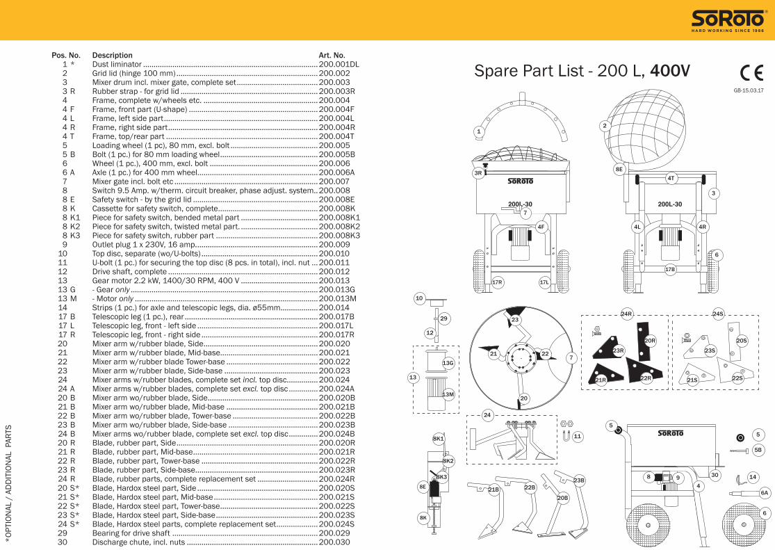
Pos. No. Description Art. No. 1 * Dust liminator ....................................................................................200.001DL 2 Grid lid (hinge 100 mm) ....................................................................200.002 3 Mixer drum incl. mixer gate, complete set .......................................200.003 3 R Rubber strap - for grid lid ..................................................................200.003R 4 Frame, complete w/wheels etc. .......................................................200.004 4 F Frame, front part (U-shape) ..............................................................200.004F 4 L Frame, left side part ..........................................................................200.004L 4 R Frame, right side part ........................................................................200.004R 4 T Frame, top/rear part .........................................................................200.004T 5 Loading wheel (1 pc), 80 mm, excl. bolt ..........................................200.005 5 B Bolt (1 pc.) for 80 mm loading wheel ...............................................200.005B 6 Wheel (1 pc.), 400 mm, excl. bolt ....................................................200.006 6 A Axle (1 pc.) for 400 mm wheel..........................................................200.006A 7 Mixer gate incl. bolt etc .....................................................................200.007 8 Switch 9.5 Amp. w/therm. circuit breaker, phase adjust. system..200.008 8 E Safety switch - by the grid lid ............................................................200.008E 8 K Cassette for safety switch, complete ................................................200.008K 8 K1 Piece for safety switch, bended metal part .....................................200.008K1 8 K2 Piece for safety switch, twisted metal part. .....................................200.008K2 8 K3 Piece for safety switch, rubber part .................................................200.008K3 9 Outlet plug 1 x 230V, 16 amp. ..........................................................200.009 10 Top disc, separate (wo/U-bolts) ........................................................200.010 11 U-bolt (1 pc.) for securing the top disc (8 pcs. in total), incl. nut ...200.011 12 Drive shaft, complete ........................................................................200.012 13 Gear motor 2.2 kW, 1400/30 RPM, 400 V .....................................200.013 13 G - Gear only ..........................................................................................200.013G 13 M - Motor only ........................................................................................200.013M 14 Strips (1 pc.) for axle and telescopic legs, dia. ø55mm ..................200.014 17 B Telescopic leg (1 pc.), rear ................................................................200.017B 17 L Telescopic leg, front - left side ..........................................................200.017L 17 R Telescopic leg, front - right side ........................................................200.017R 20 Mixer arm w/rubber blade, Side .......................................................200.020 21 Mixer arm w/rubber blade, Mid-base...............................................200.021 22 Mixer arm w/rubber blade Tower-base ............................................200.022 23 Mixer arm w/rubber blade, Side-base .............................................200.023 24 Mixer arms w/rubber blades, complete set incl. top disc ...............200.024 24 A Mixer arms w/rubber blades, complete set excl. top disc ..............200.024A 20 B Mixer arm wo/rubber blade, Side .....................................................200.020B 21 B Mixer arm wo/rubber blade, Mid-base ............................................200.021B 22 B Mixer arm wo/rubber blade, Tower-base .........................................200.022B 23 B Mixer arm wo/rubber blade, Side-base ...........................................200.023B 24 B Mixer arms wo/rubber blade, complete set excl. top disc ..............200.024B 20 R Blade, rubber part, Side ....................................................................200.020R 21 R Blade, rubber part, Mid-base ............................................................200.021R 22 R Blade, rubber part, Tower-base ........................................................200.022R 23 R Blade, rubber part, Side-base ...........................................................200.023R 24 R Blade, rubber parts, complete replacement set .............................200.024R 20 S* Blade, Hardox steel part, Side ..........................................................200.020S 21 S* Blade, Hardox steel part, Mid-base ..................................................200.021S 22 S* Blade, Hardox steel part, Tower-base ...............................................200.022S 23 S* Blade, Hardox steel part, Side-base .................................................200.023S 24 S* Blade, Hardox steel parts, complete replacement set ....................200.024S 29 Bearing for drive shaft ......................................................................200.029 30 Discharge chute, incl. nuts ...............................................................200.030
*OPT
ION
AL /
AD
DIT
ION
AL P
ARTS
12
5
6
3
7
7
84
9 30 14
12
23
22
20
21
20B21B
8K1
8K2
8K3
8E
8K
22B23B
11
13M
17R 17L
17B
10
29
3R
5
6
6A
5B
13G
8E4T
4R4L4F
24R
24
24S
21R 21S22R 22S
23R 23S
20R 20S
13
Spare Part List - 200 L, 400VGB-15.03.17

GB / 22 23 / GB
Pos.No Description Art. No. 1 * Dust liminator .........................................................................................300.001DL 2 Grid lid (hinge 100 mm).........................................................................300.002 3 Mixer drum incl. mixer gate, complete set ...........................................300.003 3 R Rubber strap - for grid lid .......................................................................300.003R 4 Frame, complete w/wheels etc. ............................................................300.004 5 Wheel (1 pc.), 250 mm, excl. bolt .........................................................300.005 5 A Bolt, 10x120 mm, for 250 mm wheel, incl. nut ...................................300.005A 6 Wheel (1 pc.), 400 mm, excl. bolt .........................................................300.006 6 A Axle (1 pc.) for 400 mm wheel ..............................................................300.006A 7 Mixer gate incl. bolt etc. .........................................................................300.007 8 Switch 9.5 Amp. w/therm. circuit breaker, phase adj. system ...........300.008 8 E Safety switch - by the grid lid .................................................................300.008E 8 K Cassette for safety switch, complete ....................................................300.008K 8 K1 Piece for safety switch, bended metal part ..........................................300.008K1 8 K2 Piece for safety switch, twisted metal part ...........................................300.008K2 8 K3 Piece for safety switch, rubber part ......................................................300.008K3 9 Outlet plug 1 x 230V 16 Amp. ...............................................................300.009 10 Top disc, separate (w/U-bolts)...............................................................300.010 10 A Top disc, separate (wo/U-bolts and nuts) .............................................300.010A 11 U-bolt (1 pc.) for securing top disc (8 pcs. needed in total) ................300.011 12 Drive shaft, complete .............................................................................300.012 13 Gear motor 3.0 kW, 1400/30 RPM, 400V ...........................................300.013 13 G - Gear only ...............................................................................................300.013G 13 M - Motor only .............................................................................................300.013M 14 Strips (1 pc.) for the axle and telescopic legs, dia. ø55mm ................300.014 15 Telescopic leg (1 pc.) .............................................................................300.015 17 * Pole excl. globe coupling .......................................................................300.017 17 A Stud bolt for pole ....................................................................................300.017A 18 * Globe coupling incl. bolt and nut ..........................................................300.018 19 Spring for grid lid ....................................................................................300.019 19 A D-shackle bolt for spring ........................................................................300.019A 20 Mixer arm w/rubber blade, Side ...........................................................300.020 21 Mixer arm w/rubber blade, Mid-base ...................................................300.021 22 Mixer arm w/rubber blade, Tower-base ................................................300.022 23 Mixer arm w/rubber blade, Side-base .................................................. 300.023 24 Mixer arms w/rubber blade, complete set incl. top disc .....................300.024 24 A Mixer arms w/rubber blade, complete set excl. top disc ....................300.024A 20 B Mixer arm wo/rubber blade, Side .........................................................300.020B 21 B Mixer arm wo/rubber blade Mid-base ..................................................300.021B 22 B Mixer arm wo/rubber blade, Tower-base ..............................................300.022B 23 B Mixer arm wo/rubber blade, Side-base ................................................300.023B 20 R Blade, rubber part, Side ........................................................................300.020R 21 R Blade, rubber part, Mid-base ................................................................300.021R 22 R Blade, rubber part, Tower-base .............................................................300.022R 23 R Blade, rubber part, Side-base ...............................................................300.023R 24 R Blades, rubber part, complete replacement set .................................300.024R 20 S* Blade, Hardox steel, Side.......................................................................300.020S 21 S* Blade, Hardox steel, Mid-base ..............................................................300.021S 22 S* Blade, Hardox steel, Tower-base ...........................................................300.022S 23 S* Blade, Hardox steel, Side-base .............................................................300.023S 24 S* Blades, Hardox steel, complete replacement set ................................300.024S 25 * TURBO mixer arm (for mixing builder’s mortar) ** .............................300.025 29 Bearing for drive shaft ...........................................................................300.029 30 Discharge chute ...................................................................................300.030
* OP
TION
AL /
AD
DIT
ION
AL P
ARTS
**
Pos
.No.
21
is re
plac
ed b
y po
s.no
. 25
8K3
9
10
11
12
29
13G
13M
30
1718
19
19A
20
2122
23
20R
20S 20B21B
22R
22S
22B
23R
23S23B
25
21R
21S
15
10A
8K2
8K1
8K
8E
8E
8
7
7
6A
14
5A
5
6
4
3
3R
2
1
24S
24R
24A
13
Spare Part List - 300 L, 400VGB-15.03.17

EU Declaration of ConformityAnnex II.A of the Machinery Directive
Manufacturer: SoRoTo
Address: Fabriksparken 11-13, 2600 Glostrup, DENMARK
Product: Forced Action Mixers
Model: 40L-30, 65 light, 80L-30, 100L-30, 120L-30, 200L-30 and 300L-30
Manufactured: From 2015 and onwards
We hereby declare that the SoRoTo Forced Action Mixers are manu-factured in conformity with the stipulation containted in COUNCIL DIRECTIVE No. 2006/42/EC on the approximation of the laws of member states on machine, including subsequent modifications, with special re-gard to Annex I of the directive on important safety and health require-ments in connection with the design and manufacture of machines.
Furthermore, we declare that the SoRoTo Forced Action Mixers are manufactured in conformity with the following harmonised standard,
EN 12151:2007
15.03.2017Glostrup, DENMARK
________________________Hans Terney RasmussenCEO
Original FABRIKSPARKEN 11-13 DK-2600 GLOSTRUP