manual for operator training - xrf.guru · parts of the atom just as all things are composed of...
TRANSCRIPT

030.0011.01.0
X-Ray Radiation Safety Manual for Operator Training
Bruker Elemental Hand-held XRF Analyzers

X-Ray Radiation Safety Manual
030.0011.01.0 ii
Table of Contents Important Notes to Hand Held XRF Analyzer Customers .......................................................................... 1
General Information .................................................................................................................................. 1
Responsibilities of the Customer .............................................................................................................. 2
Section 1: Radiation Safety .................................................................................................... 3
What is Radiation? .................................................................................................................................... 4
The Composition of Matter ................................................................................................................... 4
Parts of the Atom................................................................................................................................... 5
Protons .............................................................................................................................................. 5
Neutrons ........................................................................................................................................... 5
Electrons ........................................................................................................................................... 5
Structure of the Atom ............................................................................................................................ 5
Nucleus .............................................................................................................................................. 5
Electrons ........................................................................................................................................... 6
Electrical Charge of the Atom ................................................................................................................ 6
The Stability of the Atom ....................................................................................................................... 6
Radiation Terminology .............................................................................................................................. 7
Types of Radiation ..................................................................................................................................... 8
Non-ionizing Radiation .......................................................................................................................... 8
Ionizing Radiation .................................................................................................................................. 8
Alpha particles .................................................................................................................................. 9
Beta Particles .................................................................................................................................... 9
Gamma Rays and X-rays .................................................................................................................. 10
Neutron Particles ............................................................................................................................ 10
Units of Measuring Radiation .............................................................................................................. 11
Roentgen ......................................................................................................................................... 11
Rad (Radiation Absorbed Dose) ...................................................................................................... 11
Rem ................................................................................................................................................. 11
Radiation Quality Factor ................................................................................................................. 11
Dose Equivalence ............................................................................................................................ 12
Dose and Dose Rate ........................................................................................................................ 12

X-Ray Radiation Safety Manual
030.0011.01.0 iii
Sources of Radiation ............................................................................................................................ 12
Natural Sources ............................................................................................................................... 12
Man-made Sources ......................................................................................................................... 14
Average Occupational Doses .......................................................................................................... 15
Significant Doses ............................................................................................................................. 15
Biological Effects of Radiation ................................................................................................................. 16
Cell Sensitivity ...................................................................................................................................... 16
Acute and Chronic Doses of Radiation ................................................................................................ 16
Acute Dose ...................................................................................................................................... 16
Radiation Sickness ........................................................................................................................... 16
Acute Dose to the Whole Body ....................................................................................................... 16
Acute Dose to Part of the Body....................................................................................................... 16
Chronic Dose ................................................................................................................................... 17
Chronic Dose vs. Acute.................................................................................................................... 17
Genetic Effects ................................................................................................................................ 17
Somatic Effects ................................................................................................................................ 17
Heritable Effects .............................................................................................................................. 17
Biological Damage Factors ................................................................................................................... 17
Prenatal Exposure ................................................................................................................................ 18
Putting Risks in Perspective ................................................................................................................. 18
Risk Comparison .............................................................................................................................. 18
Radiation Dose Limits .............................................................................................................................. 20
Whole Body ......................................................................................................................................... 20
Extremities ........................................................................................................................................... 20
Skin ...................................................................................................................................................... 20
Organs or Tissues (excluding lens of the eye and the skin) ................................................................. 20
Lens of the Eye ..................................................................................................................................... 21
Declared Pregnant Worker (embryo/fetus) ........................................................................................ 21
Measuring Radiation ............................................................................................................................... 22
Measuring Devices ............................................................................................................................... 22
Ionization Chamber ......................................................................................................................... 22

X-Ray Radiation Safety Manual
030.0011.01.0 iv
The Geiger-Mueller Tube ................................................................................................................ 22
The Pocket Dosimeter ..................................................................................................................... 22
Thermoluminescence Devices (TLDs) and Optically Simulated Luminescence Dosimeter (OSL) ... 23
Dosimeters ...................................................................................................................................... 23
Reducing Exposure (ALARA Concept) ...................................................................................................... 24
Time ..................................................................................................................................................... 24
Distance ............................................................................................................................................... 24
Shielding .............................................................................................................................................. 25
License/Registration Requirements ........................................................................................................ 27
Bruker Elemental X-ray Tube XRF Analyzer ......................................................................................... 27
Transportation Requirements ................................................................................................................. 28
Section 2: Theory of XRF Operation ..................................................................................... 29
What Is XRF? ............................................................................................................................................ 30
Review: The Composition of Matter ................................................................................................... 30
The Molecule .................................................................................................................................. 30
Structure of the Atom ..................................................................................................................... 30
The Electron .................................................................................................................................... 30
The Nucleus ..................................................................................................................................... 31
Nuclear Stability .............................................................................................................................. 31
X-ray Emissions ............................................................................................................................... 31
How XRF Works ................................................................................................................................... 31
The Process of X-ray Fluorescence ................................................................................................. 32
Bruker Elemental XRF Instruments ......................................................................................................... 33
Characteristic X-rays ............................................................................................................................ 33
X-ray Line Interference ........................................................................................................................ 34
Scattered X-rays—Compton ................................................................................................................ 34
Intensity Concentration Relation ......................................................................................................... 34
Data Reduction ........................................................................................................................................ 36
Errors in XRF Analysis........................................................................................................................... 36
Systematic and Random Errors ........................................................................................................... 36
Accuracy, Precision, and Bias............................................................................................................... 36

X-Ray Radiation Safety Manual
030.0011.01.0 v
Precision .......................................................................................................................................... 36
Bias .................................................................................................................................................. 36
Gaussian Distribution .......................................................................................................................... 37
Standard Deviation .............................................................................................................................. 37
Reducing Error ................................................................................................................................ 38
X-ray Detection .................................................................................................................................... 38
Counting Statistics ............................................................................................................................... 38
Spectrum Accumulation ...................................................................................................................... 39
Spectral Resolution .............................................................................................................................. 39
The Spectrum ....................................................................................................................................... 39
Calculation of Net Intensities .............................................................................................................. 40
Background ..................................................................................................................................... 40
Spectral Overlap .............................................................................................................................. 40
Eliminating Background and Overlap .................................................................................................. 40
Calculating Concentrations .................................................................................................................. 40
Section 3: Specific XRF User Requirements .......................................................................... 41
Handheld XRF Analyzer Applications ...................................................................................................... 42
Radiation from the XRF Analyzer ............................................................................................................ 43
Radiation Scatter ................................................................................................................................. 43
Backscatter .......................................................................................................................................... 43
Handheld XRF Analyzer Safety Design..................................................................................................... 44
Tracer Analyzer Radiation Profile ............................................................................................................ 45
Safety Logic Circuit, Warning Lights, and Warning Labels ...................................................................... 46
XRF Analyzer Safety Signs ........................................................................................................................ 47
Radiation Safety Tips for Using the XRF Analyzer ................................................................................... 48
In Case of Emergencies ........................................................................................................................... 49
Minor Damage ..................................................................................................................................... 49
Major Damage ..................................................................................................................................... 49
Loss or Theft ........................................................................................................................................ 49
Appendices ......................................................................................................................... 50
Appendix A X-ray Critical Absorption Energies in keV .................................................................... 51

X-Ray Radiation Safety Manual
030.0011.01.0 vi
Appendix B Radiation Profile, Normal Condition ........................................................................... 53
Appendix C Tracer XRF Instrument ................................................................................................ 54
Appendix D Survey Meters: Operation and Maintenance ............................................................ 55
Contact Us ............................................................................................................................................... 57

X-Ray Radiation Safety Manual
030.0011.01.0 1
Important Notes to Hand Held XRF Analyzer Customers This Radiation Safety Operator Training manual is for use by operators of the Bruker Elemental handheld XRF analyzers. This manual contains three sections:
1. Radiation Safety (begins on page 4)
2. Theory of XRF Operation (begins on page 30)
3. Specific Bruker Elemental XRF analyzer requirements (begins on page 42)
The first two sections contain generic theory and safety issues, while section three discusses the specifics of the Tracer XRF analyzer. For detailed information about the S1 Sorter and S1 Turbo, see the instrument’s User Guide.
Recipients of Bruker Elemental XRF analyzers, which contain an X-ray tube(which differ from radioactive sourced analyzers) may be subject to X-ray protection requirements established by government agencies.
General Information Bruker Elemental (Bruker AXS Handheld, Inc. DBA Bruker Elemental) manufactures XRF analyzers that contain an X-ray tube. They are registered with the U.S. FDA Center for Devices and Radiological Health. Each purchased analyzer, which contains an X-ray tube, is provided with specific safety requirements.
All Bruker Elemental XRF analyzers should be operated only by individuals who have completed an approved radiation safety training program.
Damage to a Bruker Elemental XRF analyzer may cause unnecessary radiation exposure. If a Bruker Elemental XRF analyzer is damaged such that radiation shielding damage is suspected, a Bruker Elemental service representative should be contacted immediately at (509) 783-9850. If any hardware items are damaged, even if the instrument remains operable, contact a Bruker Elemental service representative for additional information.
Tampering with any Bruker Elemental XRF analyzer component, except to replace the batteries or to remove the hand-held computer, where applicable, voids the warranty and violates the mode of operation. In such cases, harm or serious injury may result.
► Note
Governing agencies regulate the use of X-ray generating devices such as XRF analyzers through a set of regulations. Actual regulations for all XRF analyzers vary by locale.
► Note
Bruker Elemental, as used throughout this manual, refers specifically to the device manufacturer Bruker Elemental (Bruker AXS Handheld, Inc. DBA Bruker Elemental).
► Note
Governing agencies may require registration and/or licensing. A fee payment may be required. If you are planning to transport a Bruker Elemental XRF analyzer into another jurisdiction, contact the appropriate authority in that jurisdiction for their particular requirements.

X-Ray Radiation Safety Manual
030.0011.01.0 2
Responsibilities of the Customer Contact the appropriate regulatory authority to determine if registration or licensing requirements apply.
Comply with all instructions and labels provided with the XRF.
Do not remove labels. Removal of labels will void the warranty.
Test an XRF device for correct operation of the ON/OFF mechanism every six months and keep records of the test results. If the instrument fails either test, call Bruker Elemental immediately for instructions and return of the instrument for repair.
Do not abandon any XRF instrument.
Maintain a record of the XRF instrument use and any service to shielding and/or containment mechanisms for two years, or until the ownership of the instrument is transferred, or until the instrument is decommissioned.
Report any possible damage to shielding, or any loss or theft of the instrument, to the appropriate authority.
Transfer the instrument only to persons specifically authorized to receive it, and report any transfer to the appropriate regulatory authority, normally 15 to 30 days following the purchase, if required.
Report the transfer of the instrument to Bruker Elemental at (509) 783-9850.

X-Ray Radiation Safety Manual
030.0011.01.0 3
Section 1: Radiation Safety

X-Ray Radiation Safety Manual
030.0011.01.0 4
What is Radiation? The term radiation is used with all forms of energy: light, X-rays, radar, microwaves, and more. However, for the purpose of this manual, radiation refers to invisible waves or particles of energy from radioactive sources or X-ray tubes.
High levels of radiation may pose a danger to living tissue because they have the potential to damage and/or alter the chemical structure of cells. This could result in various levels of illness, ranging from mild to severe.
This section provides a basic understanding of radiation characteristics. This should help in preventing unnecessary radiation exposure to Bruker Elemental customers, users, and staff while using the Bruker Elemental XRF analyzers. The concepts have been simplified to give a cursory picture of what radiation is and how it applies to the manufacturing staff and operators of Bruker Elemental XRF analyzers.
The Composition of Matter To help you understand radiation, we’ll start by briefly discussing the composition of matter.
The physical world is composed of key materials called elements. The basic unit of every element is the atom. Although microscopic, each atom has all the chemical characteristics of its element.
All substances or materials are made from atoms of different elements combined together in specific patterns. That is why atoms are called the basic building blocks of matter.
Example: Oxygen and hydrogen are two very common elements. If we combine one atom of oxygen and two atoms of hydrogen, the result is a molecule of H2O, or water.
An Atom

X-Ray Radiation Safety Manual
030.0011.01.0 5
Parts of the Atom Just as all things are composed of atoms, atoms are made up of three basic particles: protons, neutrons, and electrons. Together, these particles determine the properties, electrical charge, and stability of an atom.
Protons
Are found in the nucleus of the atom
Have a positive electrical charge
Determine the atomic number of the element; therefore, if the number of protons in the nucleus changes, the element changes
Neutrons
Are found in the nucleus of the atom
Have no electrical charge
Help determine the stability of the nucleus
Are in the nucleus of every atom except Hydrogen (H-1)
Atoms of the same element have the same number of protons, but can have a different number of neutrons.
Electrons
Are found orbiting around the nucleus at set energy levels or shells (K and L shells are important in X-ray fluorescence)
Have a negative electrical charge
Determine chemical properties of an atom
Have very little mass
Structure of the Atom The design or atomic structure of the atom has two main parts: the nucleus, and the electron shells that surround the nucleus.
Nucleus
Is the center of an atom
Is composed of protons and neutrons
Produces a positive electrical field
Makes up nearly the entire mass of the atom

X-Ray Radiation Safety Manual
030.0011.01.0 6
Electrons
Circle the nucleus of an atom in a prescribed orbit
Have a specific number of electrons
Produce a negative electrical field
Are the principle controls in chemical reactions
The protons and neutrons that form the nucleus are bound tightly together by powerful nuclear forces. Electrons (-) are held in orbit by their electromagnetic attraction to the protons (+). When these ratios become unbalanced, the electrical charge and stability of the atom are affected.
Electrical Charge of the Atom The ratio of protons and electrons determine whether the atom has a positive, negative, or neutral electrical charge. The term ion is used to define atoms or groups of atoms that have a positive or negative electrical charge.
• Positive Charge (+)—If an atom has more protons than electrons, the charge is positive.
• Negative Charge (-)—If an atom has more electrons than protons, the charge is negative.
• Neutral (No Charge)—If an atom has an equal number of protons and electrons, it is neutral, or has no net electrical charge.
The process of removing electrons from a neutral atom is called ionization.
Atoms that develop a positive or negative charge (gain or lose electrons) are called ions. When an electrically neutral atom loses an electron, that electron and the now positively charged atom are called an ion pair.
The Stability of the Atom The concept of stability of an atom is related to the structure and the behavior of the nucleus:
• Every stable atom has a nucleus with a specific combination of neutrons and protons.
• Any other combination or neutrons and protons results in a nucleus that has too much energy to remain stable.
• Unstable atoms try to become stable by releasing excess energy in the form of particles or waves (radiation).
The process of unstable atoms releasing excess energy is called radioactivity or radioactive decay.

X-Ray Radiation Safety Manual
030.0011.01.0 7
Radiation Terminology Before examining the subject of radiation in more detail, there are several important terms to be reviewed and understood.
Bremsstrahlung: The X-rays or “braking” radiation produced by the deceleration of electrons, namely in an X-ray tube.
Characteristic X-rays: X-rays emitted from electrons during electron shell transfers.
Fail-Safe Design: A design in which any reasonably anticipated failure of an indicator or safety component will cause the equipment to fail in a mode such that personnel are safe from exposure to radiation (e.g., a light indicating “X-RAY ON” fails, the production of X-rays shall be prevented).
Ion: An atom that has lost or gained an electron.
Ion Pair: A free electron and positively charged atom.
Ionization: The process of removing electrons from the shells of neutral atoms.
Ionizing Radiation: Radiation that has enough energy to remove electrons from neutral atoms.
Isotope: Atoms of the same element that have a different number of neutrons in the nucleus.
Non-ionizing Radiation: Radiation that does not have enough energy to remove electrons from neutral atoms.
Normal Operation: Operation under conditions suitable for collecting data as recommended by manufacturer, including shielding and barriers.
Primary Beam: In the context of X-ray fluorescence measurements, the primary beam is the ionizing radiation from an X-ray tube that is directed through an aperture in the radiation source housing.
Radiation: The energy in transit, in form of electromagnetic waves or particles.
Radiation Generating Machine: A device that generates X-rays by accelerating electrons, which strike an anode.
Radiation Source: An X-ray tube or radioactive isotope.
Radiation Source Housing: That portion of an X-ray fluorescence (XRF) system, which contains the X-ray tube or radioactive isotope.
Radioactive Material: Any material or substance that has unstable atoms that are emitting radiation.
System Barrier: That portion of an area that clearly defines the transition from a controlled area to a radiation area and provides the necessary shielding to limit the dose rate in the controlled area during normal operation.
X-ray Generator: That portion of an X-ray system that provides the accelerating voltage and current for the X-ray tube.
X-ray System: Apparatus for generating and using ionizing radiation, including all X-ray accessory apparatus, such as accelerating voltage and current for the X-ray tube and any needed shielding.

X-Ray Radiation Safety Manual
030.0011.01.0 8
Types of Radiation Radiation consists of invisible waves or particles of energy that, if received in too large a quantity, can have an adverse health effect on humans. There are two distinct types of radiation: non-ionizing and ionizing.
Non-ionizing Radiation Non-ionizing radiation does not have the energy necessary to ionize an atom (i.e., to remove electrons from neutral atoms).
Sources of non-ionizing radiation include light, microwaves, power lines, and radar.
Although this type of radiation can cause biological damage, such as sunburn, it is generally considered less hazardous than ionizing radiation.
Ionizing Radiation Ionizing radiation does have enough energy to remove electrons from neutral atoms. Ionizing radiation is of concern due to its potential to alter the chemical structure of living cells. These changes can alter or impair the normal functions of a cell. Sufficient amounts of ionizing radiation can cause hair loss, blood changes, and varying degrees of illness.
There are four basic types of ionizing radiation, emitted from different parts of the atom:
• Alpha particles
• Beta Particles
• Gamma rays or X-rays
• Neutron Particles
The penetrating power for each of the four basic radiations varies significantly.
Types of Ionizing Radiation and Their Sources
► Note
Tracer XRF devices emit only X-rays.
The Penetrating Power of Radiation

X-Ray Radiation Safety Manual
030.0011.01.0 9
Alpha particles
Have a large mass, consisting of two protons and two neutrons
Have a positive charge and are emitted from the nucleus
Ionize by stripping away electrons (-) from other atoms with its positive (+) charge
Range
Due to their large mass and charge, alpha particles will only travel about one to two inches in air. This also limits its penetrating ability.
Shielding
Most alpha particles will be stopped by a piece of paper, several centimeters of air, or the outer layer (i.e., dead layer) of the skin.
Hazard
Due to limited range and penetration ability, alpha particles are not considered an external radiation hazard. However, since it can deposit large amounts of concentrated energy in small volumes of body tissue if inhaled or ingested, alpha radiation is a potential internal hazard.
Beta Particles
Have a small mass and a negative charge (-), similar to an electron
Are emitted from the nucleus of an atom
Ionize other atoms by pushing electrons out of their orbits with their negative charge
Range
Small mass and a negative charge give the beta particle a range of about 10 feet in air. The negative charge limits penetrating ability.
Shielding
Most beta particles can be stopped by a few millimeters of plastic, glass, or metal foil, depending on the density of the material.
Hazard
Although beta particles have a fairly short range, they are still considered an external radiation hazard, particularly to the skin and eyes. If ingested or inhaled, beta radiation may pose a hazard to internal tissues.

X-Ray Radiation Safety Manual
030.0011.01.0 10
Gamma Rays and X-rays
Are electromagnetic waves or photons of pure energy that have no mass or electrical charge
Are identical except that gamma rays come from the nucleus, while X-rays come from the electron shells or from an X-ray generating machine
Ionize atoms by interacting with electrons
Range
Because gamma and X-rays have no charge or mass, they are highly penetrating and can travel quite far. Range in air can easily reach several hundred feet.
Shielding
Gamma and X-rays are best shielded by use of dense materials, such as concrete, lead, or steel.
Hazard
Due to their range and penetrating ability, gamma and X-ray radiation primarily are considered an external hazard.
Neutron Particles
Create radiation when neutrons are ejected from the nucleus of an atom
Are produced during the normal operation of a nuclear reactor or particle accelerator, as well as the natural decay process of some radioactive elements.
Can split atoms by colliding with their nuclei, forming two or more unstable atoms. This is called fission. These atoms then may cause ionization as they try to become stable.
Can also be absorbed by some atoms (captured) without causing fission, occasionally resulting in the creation of a radioactive atom dependent on the absorber. This is called fusion.
Range
Since neutrons have no electrical charge, they have a high penetrating ability and require thick shielding material to stop. Range in air can be several hundred feet.
Shielding
The best materials to shield against neutron radiation are those with high hydrogen content (water, concrete, or plastic).
Hazard
Neutron radiation primarily is considered an external hazard due to its range and penetrating ability.

X-Ray Radiation Safety Manual
030.0011.01.0 11
Units of Measuring Radiation The absorption of radiation into the body, or anything else, depends upon two things: the type of radiation involved and the amount of radiation energy received. The units for measuring radiation are the roentgen, rad, and rem.
Roentgen
A roentgen is named after Wilhelm Roentgen, the discoverer of X-rays. A roentgen is a unit of exposure dose that measures X-rays or gamma rays in terms of the ions or electrons produced in dry air at 0° C and one atmosphere, equal to the amount of radiation producing one electrostatic unit of positive or negative charge per cubic centimeter of air.
Rad (Radiation Absorbed Dose)
A rad is:
• A unit for measuring the amount of radiation energy absorbed by a material (i.e. dose)
• Defined for any material (e.g., 100 ergs/g).
• Applied to all types of radiation.
• Not related to biological effects of radiation in the body.
• 1.0 Rad = 1000 millirad (mrad)
• The Gray (Gy) is the System International (SI) unit for absorbed energy.
• 1.0 Rad = 0.01 Gy; 1.0 Gy = 100 rad.
Rem
Actual biological damage depends upon the concentration, as well as the amount, of radiation energy deposited in the body. The rem is used to quantify overall doses of radiation, their ability to cause damage, and their dose equivalence :
• Is a unit for measuring dose equivalence
• Is the most commonly used unit of radiation exposure measure
• Pertains directly to humans
• Takes into account the effects of energy absorbed (dose) in humans; the biological effect of different types of radiation in the body and any other factors. For gamma and X-ray radiation, all of these factors are equivalent, so that for these purposes a rad and a rem are numerically equal.
• Sievert is the SI unit for dose equivalence
• 1 rem = 1000 millirem (mrem)
• 1 rem = 0.01 Sievert (Sv) and 1Sv = 100 rem
Radiation Quality Factor
Quality Factor (QF) is a numerical value given to each type of radiation based on its potential to produce biological damage.

X-Ray Radiation Safety Manual
030.0011.01.0 12
Quality Factors for the various types of radiation are:
X-ray, Gamma ray, beta 1 Neutron (Fast) 10 Alpha 20
Dose Equivalence
The rem is used to determine dose equivalence and is equal to the dose in rads times a Quality Factor, or
rem = rad x Quality Factor
Example: A worker at a nuclear power plant is involved in a clean-up operation and receives a 0.17 rad dose of neutron radiation. Neutron radiation has a QF of 10, which results in a dose of 1.7 rems (0.17 rad x 10 QF = 1.7 rems).
Dose and Dose Rate
Dose is the amount of radiation received during any exposure.
Dose Rate is the rate at which you receive the dose.
Sources of Radiation We live in a radioactive world and always have. As human beings, we have evolved in the presence of ionizing radiation from natural background radiation.
Whether or not a person is working with radioactive materials, no one can completely avoid exposure to radiation. We are continually exposed to sources of radiation from our environment, both natural and man-made.
The average person in the U.S. receives about 360 millirem (mrem) of radiation per year. The average annual radiation dose in the state of Colorado is 450-500 mrem per year.
Natural Sources
Most of our radiation exposure comes from natural sources (about 300 mrem per year). In fact, most of the world's population will be exposed to more ionizing radiation from natural sources than they will ever receive on the job.
There are several sources of natural background radiation. The radiation from these sources is exactly the same as that from man-made sources.
The four major sources of natural radiation include:
• Cosmic Radiation
• Terrestrial Radiation (sources in the earth's crust)
• Sources (sources in the human body such as K-40 e.g. eating bananas), also referred to as internal sources
Example: 1) Dose rate = dose/time = mrem/hr 2) Dose = dose rate x time = mrem

X-Ray Radiation Safety Manual
030.0011.01.0 13
• Radon, Uranium, and Thorium
Cosmic Radiation
Comes from the sun and outer space
Is composed of positively charged particles and gamma radiation
Increases in intensity at higher altitudes because there is less atmospheric shielding
The average dose received by the general public from cosmic radiation is approximately 28 mrem per year.
Example: The population of Denver, Colorado, receives twice the radiation exposure from cosmic rays as people living at sea level.
Terrestrial Radiation
There are natural sources of radiation in the soil, rocks, building materials, and drinking water. Some of the contributors to these sources include naturally radioactive elements such as radium, uranium, and thorium. Many areas have elevated levels of terrestrial radiation due to increased concentrations of Uranium or Thorium in the soil. The average dose received by the general public from terrestrial radiation is about 28 mrem per year.
Internal Sources
The food we eat and the water we drink all contain some trace amount of natural radioactive materials. These naturally occurring radioactive isotopes include Na-24, C-14, Ar-41 and K-40. Most of our internal exposure comes from K-40.
There are four ways to receive internal exposure:
• Breathing
• Swallowing (ingestion)
• Absorption through the skin
• Wounds (breaks in the skin)
The average dose received by the general public from internal sources is about 40 mrem per year.
Examples of Internal Exposure: 1) Inhalation of radon or dust from other radioactive materials 2) Potassium-40 in bananas 3) Water containing traces of uranium, radium, or thorium 4) Handling of a specified radioactive material without protective gear or with an
unhealed cut

X-Ray Radiation Safety Manual
030.0011.01.0 14
Radon
Comes from the radioactive decay of radium, which is naturally present in soil
Is a gas, which can travel through soil and collect in basements or other areas of the home
Emits alpha radiation. Because alpha radiation cannot penetrate the dead layer of skin on your body, it presents a hazard only if taken into the body
Is the largest contributor of natural occurring radiation
Radon and its decay products are present in the air. When inhaled, they can cause a dose to the lung
Man-made Sources
In addition to natural background radiation, some exposure comes from man-made sources that are part of our everyday lives. These sources account for approximately 65 mrem per year of the average annual radiation dose.
The four major sources of man-made radiation exposures are:
• Medical radiation (approximately 53 mrem per year)
• Consumer products (approximately 10 mrem per year)
• Industrial uses (less than 3 mrem per year)
• Atmospheric testing of nuclear weapons (less than 1 mrem per year)
Medical Radiation
Medical radiation involves exposure from medical procedures such as X-rays (chest, dental, etc.), CAT scans, and radiotherapy. The typical dose received from a single chest X-ray is about 10 mrem per exposure.
Radioactive sources used in medicine for diagnosis and therapy result in an annual average dose to the general population of 14 mrem.
The average dose received by the general public from all medical procedures is about 53 mrem per year.
Consumer Products
These include such products as:
• TVs
• Building materials
• Combustible fuels
• Smoke detectors
• Camera lenses
• Welding rods

X-Ray Radiation Safety Manual
030.0011.01.0 15
The total average dose received by the general public from all these products is about 10 mrem per year.
Industrial uses
Industrial uses include X-ray generating machines used to test all sorts of welds, material integrity, bore holes, and to perform microscopic analyses of materials.
The average dose received by the general public from industrial uses is less than 1 mrem per year.
Atmospheric testing of nuclear weapons
The testing of nuclear weapons during the 1950s and early 1960s resulted in fallout of radioactive materials. This practice is now banned by most nations. The average dose received by the general public from residual fallout is approximately 1 mrem per year.
Significant Doses
The general public is exposed daily to small amounts of radiation. However, there are four major groups of people that have been exposed in the past to significant levels of radiation. Because of this, we know much about ionizing radiation and its biological effects on the body.
These four major groups include:
• The earliest radiation workers, such as radiologists, who received large doses of radiation before biological effects were recognized. Since then, safety standards have been developed to protect such employees.
• The more than 100,000 people who survived the atomic bombs dropped on Hiroshima and Nagasaki. It is estimated these survivors received radiation doses in excess of 50,000 mrem.
• Those involved in radiation accidents, like Chernobyl (thirty firefighters received acute doses in excess of 800,000 mrem).
• People who have received radiation therapy for cancer. This is the largest group of people to receive significant doses of radiation.
Typical Radiation Doses from Selected Sources (Annual)
Average Occupational Doses
Exposure Source mrem per
year Occupation
Exposure (mrem per year)
Radon in homes 200 Airline flight crewmember 1000
Medical exposures 53 Nuclear power plant worker 700
Terrestrial radiation 30 Grand central station worker 120
Cosmic radiation 30 Medical personnel 70
Round trip US by air 5 DOE/DOE contractors 44
Building materials 3.6
Worldwide fallout <1
Natural gas range 0.2
Smoke detectors 0.0001

X-Ray Radiation Safety Manual
030.0011.01.0 16
Biological Effects of Radiation
Cell Sensitivity The human body is composed of over 50,000 billion living cells. Groups of these cells make up tissues, which in turn make up the body’s organs. Some cells are more resistant to viruses, poisons, and physical damage than others. The most sensitive cells are those that are rapidly dividing, such as those in a fetus. Radiation damage may depend on both resistance and level of activity during exposure.
Acute and Chronic Doses of Radiation All radiation, if received in sufficient quantities, can damage living tissue. The key lies in how much and how quickly a radiation dose is received. Doses of radiation fall into one of two categories: acute or chronic.
Acute Dose
An acute dose is a large dose of radiation received in a short period of time that results in physical reactions due to massive cell damage (acute effects). The body can't replace or repair cells fast enough to undo the damage right away, so the individual may remain ill for a long period of time. Acute doses of radiation can result in reduced blood count and hair loss.
Recorded whole body doses of 10,000 - 25,000 mrem have resulted only in slight blood changes with no other apparent effects.
Radiation Sickness
Radiation sickness occurs at acute doses greater than 100,000 mrem. Radiation therapy patients often experience it as a side effect of high-level exposures to singular areas. Radiation sickness may cause nausea (from cell damage to the intestinal lining), and additional symptoms such as fatigue, vomiting, increased temperature, and reduced white blood cell count.
Acute Dose to the Whole Body
Recovery from an acute dose to the whole body may require a number of months. Whole body doses of 500,000 mrem or more may result in damage too great for the body to recover from.
Example: Thirty firefighters at the Chernobyl facility lost their lives as a result of severe burns and acute radiation doses exceeding 800,000 mrem.
Only extreme cases (as mentioned above) result in doses so high that recovery is unlikely.
Acute Dose to Part of the Body
Acute dose to a part of the body most commonly occur in industry (use of X-ray machines), and often involve exposure of extremities (e.g., hand, fingers). Sufficient radiation doses may result in loss of the exposed body

X-Ray Radiation Safety Manual
030.0011.01.0 17
part. The prevention of acute doses to part of the body is one of the most important reasons for proper training of personnel.
Chronic Dose
A chronic dose is a small amount of radiation received continually over a long period of time, such as the dose of radiation we receive from natural background sources every day.
Chronic Dose vs. Acute
The body tolerates chronic doses better than acute doses because:
• Only a small number of cells need repair at any one time.
• The body has more time to replace dead or non-working cells with new ones.
• Radical physical changes do not occur as with acute doses.
Genetic Effects
Genetic effects involve changes in chromosomes or direct irradiation of the fetus. Effects can be somatic (cancer, tumors, etc.) and may be heritable (passed on to offspring).
Somatic Effects
Somatic effects apply directly to the person exposed, where damage has occurred to the genetic material of a cell that could eventually change it to a cancer cell. The chance of this occurring at occupational doses is very low.
Heritable Effects
This effect applies to the offspring of the individual exposed, where damage has occurred to genetic material that doesn't affect the person exposed, but will be passed on to offspring.
To date, only plants and animals have exhibited signs of heritable effects from radiation. This data includes the 77,000 children born to the survivors of Hiroshima and Nagasaki. The studies performed followed three generations, which included these children, their children, and their grandchildren.
Biological Damage Factors Biological damage factors are those factors, which directly determine how much damage living tissue receives from radiation exposure, and include:
• Total dose: the larger the dose, the greater the biological effects.
• Dose rate: the faster the dose is received, the less time for the cell to repair.
• Type of radiation: the more energy deposited the greater the effect.
• Area exposed: the more body area exposed, the greater the biological effects.
• Cell sensitivity: rapidly dividing cells are the most vulnerable.

X-Ray Radiation Safety Manual
030.0011.01.0 18
• Individual sensitivity to ionizing radiation:
developing embryo/fetus is the most sensitive children are the second most vulnerable the elderly are more sensitive than middle-aged adults young to middle-aged adults are the least sensitive
Prenatal Exposure A developing embryo/fetus is the most sensitive to ionizing radiation because of its rapidly dividing cells. While no inheritable effects from radiation have yet been recorded, there have been effects seen in some children exposed to radiation while in the womb.
Possible effects include:
• Slower growth
• Impaired mental development
• Childhood cancer
Some of the children from Hiroshima and Nagasaki, exposed to radiation while in the womb, were born with low birth weights and mental retardation. While it has been suggested that such exposures may also increase the risk of childhood cancer, this has not yet been proven. It is believed that only doses exceeding 15,000 mrem significantly increase this risk.
It should be stressed that many different physical and chemical factors can harm an unborn child. Alcohol, exposure to lead, and prolonged exposure in hot tubs are just a few of the more publicized dangers to fetal development. See page 21 for more discussion on pregnancy and exposure.
Putting Risks in Perspective Acceptance of any risk is a very personal matter and requires that a person make informed judgments, weighing benefits against potential hazards.
Risk Comparison
The following summarizes the risks of radiation exposure:
• The risks of low levels of radiation exposure are still unknown.
• Since ionizing radiation can damage chromosomes of a cell, incomplete repair may result in the development of cancerous cells.
• There have been no observed increases of cancer among individuals exposed to occupational levels of ionizing radiation.
Using other occupational risks and hazards as guidelines, nearly all scientific studies have concluded the risks of occupational radiation doses are acceptable by comparison.

X-Ray Radiation Safety Manual
030.0011.01.0 19
Average Estimated Days Lost By Industrial Occupations
Average Lifetime Estimated Days Lost Due to Daily Activities
Occupation* Estimated Days Lost
Activity* Estimated Days Lost
Mining/Quarrying 328 Cigarette smoking 2250
Construction 302 25% Overweight 1100
Agriculture 277 Accidents (all types) 435
Transportation/Utilities 164 Alcohol consumption (U.S. avg.) 365
Radiation dose of 5 rem per yr for 30 years 150 Driving a motor vehicle 207
All industry 74 Medical X-rays (U.S. avg.) 6
Government 55 1 rem Occupational Exposure 1
Service 47 1 rem per year for 30 years 30
Manufacturing 43 * Note: based on US data only
Trade 30
No matter what you do there is always some risk associated with it. For every risk there is some benefit, so as the worker, you must weigh these risks and determine if the risk is worth the benefit. Ionizing radiation is the drawback of many beneficial materials, services, and products that we use every day. By learning to respect and work safely around radiation, we can limit our exposure and continue to enjoy the benefits it provides.

X-Ray Radiation Safety Manual
030.0011.01.0 20
Radiation Dose Limits To minimize the risks from the potential biological effects of radiation, the state health departments, Nuclear Regulatory Commission (NRC) and other agencies have established radiation dose limits for occupational workers. The limits apply to those working under the provisions of a specific license or registration.
The limits described below have been developed based on information and guidance from the Environmental Protection Agency (EPA), the National Council of Radiation Protection (NCRP), the International Commission on Radiological Protection (ICRP), and the Biological Effects of Ionizing Radiation (BEIR) Committee.
Note: Radiation Dose Limits (Exposure) to someone in the general public from a licensed device must not exceed 100 mrem per year.
For an XRF analyzer, which uses an X-ray Tube as the source of X-rays, the requirement on dose limits for the operators are established by local governing agencies. In most instances, the dose limits will be similar to those established by the NRC.
In general, the larger the area of the body that is exposed, the greater the biological effects for a given dose. Extremities are less sensitive than internal organs because they do not contain critical organs. That is why the annual dose limit for extremities is higher than for a whole body exposure that irradiates the internal organs.
Your employer may have additional guidelines and set administrative control levels which you will need to be aware of to do your job safely and efficiently.
Whole Body The whole body is measured from the top of the head to just below the elbow and just below the knee.
The whole body occupational radiation dose limit in the U.S. is 5 rems (5,000 mrems) per year. This limit is based upon the total sum of both external and internal exposures.
Extremities Extremities refer to the hands, arms below the elbows, feet, and legs below the knees. In the U.S., the occupational radiation dose limit for the extremities is 50 rems per year.
Skin The occupational radiation dose limit for the skin is 50 rems per year.
Organs or Tissues (excluding lens of the eye and the skin) The occupational radiation dose limit for organs and tissues is 50 rems per year.

X-Ray Radiation Safety Manual
030.0011.01.0 21
Lens of the Eye The occupational radiation dose limit for the lens of the eye is 15 rems per year.
Declared Pregnant Worker (embryo/fetus) A female radiation worker may inform her supervisor, in writing, of her pregnancy at which time she becomes a Declared Pregnant Worker. The employer must then provide the option of a mutually agreeable assignment of work tasks, without loss of pay or promotional opportunity, such that further radiation exposure will not exceed the dose limits for the embryo/fetus.
The radiation dose limit from occupational sources for the embryo/fetus of a Declared Pregnant Worker is 500 mrem during the entire gestation. Efforts should be made to avoid doses exceeding 50 mrem per month.

X-Ray Radiation Safety Manual
030.0011.01.0 22
Measuring Radiation Since we cannot detect radiation through our senses, some regulating agencies require special devices for personnel operating an XRF in order to monitor and record the operator’s exposure. These devices are commonly referred to as dosimeters, and the use of them for monitoring is called dosimetry.
The following information applies directly to personnel using the Bruker Elemental XRF analyzers in locales that require dosimetry:
• Wear an appropriate dosimeter that can record low energy photon radiation.
• Dosimeters wear period of three months may be used – contact your local Radiation control agency.
• Each dosimeter will be assigned to a particular person and is not to be used by anyone else.
Measuring Devices
Several devices are employed for measurement of radiation doses, including ionization chambers, Geiger-Mueller tubes, pocket dosimeters, thermoluminescence devices (TLD’s), optically stimulated luminescence dosimeters (OSL), and film badges. It is the responsibility of your Radiation Safety Officer (RSO) or Radiation Protection Officer (RPO) to specify and acquire the dosimetry device or devices specified by your regulatory body for each individual and to specify any other measuring devices to be used. (See Appendix D for survey meter information and operation).
Ionization Chamber
The Ionization Chamber is the simplest type of detector for measuring radiation. It consists of a cylindrical chamber filled with air and a wire running through its center length with a voltage applied between the wire and outside cylinder. When radiation passes through the chamber, ion pairs are extracted and build up a charge. This charge is used as a measure of the exposure received. This measurement is not highly efficient (30-40% efficiency is typical), as some radiation may pass through the chamber without creating enough ion pairs for proper measurement.
The Geiger-Mueller Tube
The Geiger-Mueller (GM) Tube is very similar to the ion chamber, but is much more sensitive. The voltage of its static charge is so high that even a very small number of ion pairs will cause it to discharge.
A GM tube can detect and measure very small amounts of beta or gamma radiation.
The Pocket Dosimeter
The Pocket Dosimeter is also a specialized version of the ionization chamber. It is basically a quartz fiber electroscope. The chamber is given a single charge of static electricity, which it stores like a condenser. As radiation passes through the chamber, the charge is reduced in proportion to the amount of radiation received, and the indicator moves towards a neutral position.
A dosimeter that has been exposed to radiation must be periodically recharged, or zeroed.

X-Ray Radiation Safety Manual
030.0011.01.0 23
Thermoluminescence Devices (TLDs) and Optically Simulated Luminescence Dosimeter (OSL)
TLDs and OSL are devices that use crystals, which can store free electrons when exposed to ionizing radiation. These electrons remain trapped until the crystals are read by a special reader or processor, using heat (TLD) or light (OSL). When this occurs, the electrons are released and the crystals produce light. The intensity of the light can be measured and related directly to the amount of radiation received.
Thermoluminescent materials useful as dosimeters include lithium fluoride, lithium borate, calcium fluoride, calcium sulfate, and aluminum oxide.
Dosimeters
There are two common types of dosimeters: whole body and extremity.
Whole Body Dosimeter
A TLD or OSL whole body dosimeter is used to measure both shallow and deep penetrating radiation doses. It is normally worn between the neck and waist.
This device records a measured dose that is used as an individual's legal occupational exposure.
Finger Ring
A finger ring is a TLD in the shape of a ring, which is worn by workers to measure the radiation exposure to the extremities.
This device records a measured dose that is used as an individual's legal occupational extremity exposure.

X-Ray Radiation Safety Manual
030.0011.01.0 24
Reducing Exposure (ALARA Concept) While dose limits and administrative control levels already ensure very low radiation doses, it is possible to reduce these exposures even more.
The main goal of the ALARA program is to reduce ionizing radiation doses to a level that is As Low As Reasonably Achievable (ALARA).
ALARA is designed to prevent unnecessary exposures to employees, the public, and to protect the environment. It is the responsibility of all workers, managers, and safety personnel to ensure that radiation doses are maintained ALARA.
There are three basic practices to maintain external radiation ALARA:
• Time
• Distance
• Shielding
Time The first method of reducing exposure is to limit the amount of time spent in a radioactive area: the shorter the time of exposure, the lower the amount of exposure.
The effect of time on radiation could be stated as:
Dose = Dose Rate x Time
This means the less time you are exposed to ionizing radiation, the smaller the dose you will receive.
Example: If 1 hour of time in an area results in 100 mrem of radiation, then 1/2 an hour results in 50 mrem, 1/4 an hour would yield 25 mrem, and so on.
Distance The second method for reducing exposure is by maintaining the maximum possible distance from the radiation source to the operator or member of the public.
The principle of distance is that the exposure rate is reduced as the distance from the source is increased; as distance is increased, the amount of radiation received is reduced.
This method can best be expressed by the Inverse Square Law. The inverse square law states that doubling the distance from a point source reduces the dose rate (intensity) to 1/4 of the original. Tripling the distance reduces the dose rate to 1/9 of its original value.

X-Ray Radiation Safety Manual
030.0011.01.0 25
Expressed mathematically:
C × (D1) 2 / (D2)2 = I Variables:
C = the intensity (dose rate) of the radiation source D1 = the distance at which C was measured D2 = the actual distance from the source I = the new level of intensity at distance D2 from the source
Example: If the intensity (C) of a point source is 100 mrem/hr at one foot (D1), then at two feet (D2) it would be 25 mrem/hr (I).
C = 100 mrem/hr D1 = 1 foot D2 = 2 feet I = 25 mrem/hr C x (D1)² / (D2)² = 100 x (1)²/(2)² = 100/4 = 25 mrem/hr (I)
The inverse square law does not apply to sources of greater than a 10:1 ratio (distance: source size), or to the radiation fields produced from multiple sources.
The Inverse Square Law
Shielding The third (and perhaps most important) method of reducing exposure is shielding.
Shielding is generally considered to be the most effective method of reducing radiation exposure and consists of using a material to absorb or scatter the radiation emitted from a source before it reaches an individual.
As stated earlier, different materials are more effective against certain types of radiation than others. The shielding ability of a material also depends on its density, or the weight of a material per unit of volume.
Example: A cubic foot of lead is heavier than the same volume of concrete, and so it would also be a better shield against x-rays.

X-Ray Radiation Safety Manual
030.0011.01.0 26
Although shielding may provide the best protection from radiation exposure, there are still several precautions to keep in mind when using Bruker Elemental XRF devices:
• Persons outside the shadow cast by the shield are not necessarily 100% protected. Note: All persons not directly involved in operating the XRF should be kept at least three feet away.
• A wall or partition may not be a safe shield for persons on the other side. Note: The operator should make sure that there is no one on the other side of the wall.
• Scattered radiation may bounce around corners and reach an individual, whether directly in line with the test location or not.

X-Ray Radiation Safety Manual
030.0011.01.0 27
License/Registration Requirements
Bruker Elemental X-ray Tube XRF Analyzer The owner/operator of the Bruker Elemental X-ray tube XRF analyzer may be subject to registration with the appropriate regulatory agency. The owner/operator should:
• Contact the appropriate authority where the analyzer is to be used about regulatory requirements.
• Never remove labels from the analyzer.
• Comply with all instructions and labels provided with the device.
• Store the analyzer in a safe place where it is unlikely to be stolen or removed accidentally.
• If so equipped, keep the key separate from the analyzer. If a password is required for operation, keep the password protected.
• Maintain records of the storage, removal, and transport of the analyzer. Know its whereabouts at all times.
• Monitor operator's compliance with safe use practices. Use dosimetry where required.
• Report to the appropriate regulatory agency any damage to the shielding and any loss or theft of the analyzer.
• Sell or transfer the analyzer only to persons registered to receive it.
Notification of your local regulatory agency may be required for the transfer or disposal of the X-ray unit.

X-Ray Radiation Safety Manual
030.0011.01.0 28
Transportation Requirements Bruker Elemental X-ray Tube XRF Analyzer An owner/operator of a Bruker Elemental X-ray tube XRF analyzer may transfer custody of the analyzer to authorized (license/registration) individuals only. The owner must verify that the new recipient is authorized to receive the analyzer. No verification is required when returning it to Bruker Elemental, the original manufacturer.
There are no special Department of Transportation (DOT) interstate travel and shipping regulations for a Bruker Elemental X-ray tube XRF analyzer. The analyzer may be shipped using any means. Care should be taken if flying; it is recommended that the device be checked through due to possible concerns about the X-ray unit in the main cabin.
The owner should ensure compliance with all requirements of the jurisdiction where the X-ray tube XRF is to be used. In order to prevent inadvertant exposure of a member of the public, and in case the X-ray tube XRF analyzer is lost or stolen, the key (if so equipped) should be maintained and shipped separately. Passwords for S1 TURBO and S1 SORTERS should be protected.

X-Ray Radiation Safety Manual
030.0011.01.0 29
Section 2: Theory of XRF Operation

X-Ray Radiation Safety Manual
030.0011.01.0 30
What Is XRF? XRF stands for X-Ray Fluorescence. It is the process used by Bruker Elemental XRF analyzers to detect various elements in a matrix.
Before exploring the specifics of XRF, we’ll review some of the important concepts covered in Section One: Radiation Safety.
Review: The Composition of Matter As we learned, our world is made up of fundamental materials called elements. The basic unit of each element is the atom, which is very small, but has all the chemical characteristics of that element.
There are approximately 110 principle elements. Some of the most common elements are shown in the table to the right.
Most matter does not exist in pure elemental form, but rather in chemical combinations called molecules.
The Molecule
The molecule is the basic unit of a chemical combination. A molecule is formed when two or more atoms combine to create a material with its own distinctive properties. Atoms combine according to definite rules.
Structure of the Atom
The atom consists of two main parts: the nucleus and the electron shells.
The nucleus is the center of the atom and contains neutrons and protons, which make up almost all of the mass of the atom.
The electron cloud surrounds the nucleus and is composed of electrons that are in constant motion. For convenience, scientists draw the electrons in plain orbits, and they visualize electrons as occurring in shells surrounding the nucleus.
The Electron
Electrons orbit the nucleus in certain energy states (electron shells) in relation to the nucleus. They have a very small mass compared to the neutron and proton (i.e., approximately 2000 times less mass).
Electrons are negatively charged. The protons in the nucleus are positively charged.
When the negative charge of the electrons is equal to the positive charge of the nucleus, the two cancel each other and the atom is said to be electrically neutral.
If the two charges become unequal, the atom is said to have a net electrical charge (either positive or negative), and is called an ion. Generally, this is because an outer electron shell has gained or lost an electron.
Element Symbol Oxygen O
Sodium Na
Carbon C
Copper Cu
Hydrogen H
Iodine I
Chlorine Cl
Sulfur S
Molecule Symbol Water H20
Salt NaCl
Alcohol C2H2OH
Quartz SiO2
Common Molecules

X-Ray Radiation Safety Manual
030.0011.01.0 31
Atoms combine chemically in predictable proportion according to each element’s pattern of electrons. The orbital electrons, especially the outermost, are the controls of chemical reactions.
The Nucleus
The Nucleus is composed of protons and neutrons that are held very close together by powerful nuclear forces. Protons and neutrons are approximately equal in mass and together they make up almost the entire mass of the atom.
The charge of the proton is equal in size, but opposite in polarity, to that of the electron. Therefore, the number of protons in the nucleus must be balanced by an equal number of electrons surrounding the nucleus in order to make the atom electrically neutral. Neutrons, on the other hand, have no electrical charge and are present in all atomic nuclei except hydrogen (this does not include deuterium and tritium, which are isotopes of hydrogen).
Nuclear Stability
For each stable atom, the nucleus exists in definite combinations or ratios of protons and neutrons. Any combination or ratio other than that which defines stability results in an unstable nucleus. In the process of reaching stability, the nucleus emits one or more types of particles of energy called alpha, beta, gamma rays, or neutrons. This emission is called radiation.
X-ray Emissions
X-rays and gamma rays are both electromagnetic radiations (i.e., photons). The distinction is that gamma rays are produced and emitted from the nucleus, while X-rays are produced and emitted from the electron energy changes. For an X-ray tube, the X-rays are produced by Bremsstrahlung as accelerated electrons interact with the target material.
How XRF Works X-ray fluorescence (XRF) is the production of X-rays in the electron orbits. To understand this process we need to understand how electrons are arranged in complex atoms (see Figure 1). In atoms with many electrons, the electrons are arranged in concentric shells at increasing distances from the nucleus. These shells are labeled K, L, M, N, etc., the K shell being closest to the nucleus, the L shell the next closest, and so on. Atoms in the balanced state (non-excited) have a definite number of electrons in each shell. Each shell has a maximum number of electrons it can accommodate:
• The K shell can hold two electrons
• The L shell can hold eight electrons
• The M shell can hold 18 electrons
• The N shell can hold 32 electrons
Example: The sodium atom contains 11 electrons: two in the K shell, eight in the L shell, and a single electron in the M shell.

X-Ray Radiation Safety Manual
030.0011.01.0 32
The inner electrons are more tightly bound and require much more energy to displace them from their normal levels. As a result, a photon of much higher energy is emitted when the atom returns to its normal state after the displacement of an inner electron. The displacement of the inner electrons gives rise to the emissions of X-rays.
The Process of X-ray Fluorescence
X-rays from the Bruker Elemental XRF analyzers bombard the atoms of the target sample. Some of the generated photons collide with K (and L) shell electrons of the sample, dislodging them from their orbits. This leaves a vacant space in the K (L) shell, which is immediately filled by any electron from the L, M, or N (M or N) shell. This is accompanied by a decrease in the atom’s energy, and an X-ray photon is emitted with energy equal to this decrease.
Since the energy change is uniquely defined for atoms of a given element, it is possible to predict definite frequencies for the emitted X-rays. This means that when electrons are dislodged from atoms, the emitted X-rays are always identical. These X-rays are analyzed with an X-ray detector and the quantity of K shell and/or L shell X-rays detected will be proportional to the number of atoms of the particular element or elements present in the sample.
Figure 1. Simplified X-ray Fluorescence of an Atom production used for XRF
X-Ray Radiation Safety Manual
030.0011.01.0 33
Bruker Elemental XRF Instruments Now that we have an understanding of X-ray fluorescence, we’ll look at how it applies to the Bruker Elemental XRF analyzers.
Characteristic X-rays When X-ray (or gamma) radiation from the XRF instruments’ X-ray tube (source) excites the atoms in the sample, the atoms release fluorescent X-rays.
The energy level of each fluorescent X-ray is characteristic of the element excited. As a result, one can tell what elements are present based on the energies of the X-rays emitted.
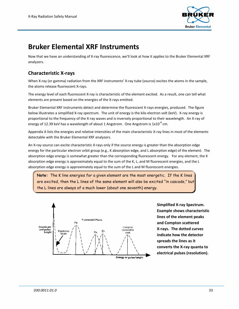
Bruker Elemental XRF instruments detect and determine the fluorescent X-rays energies, produced. The figure below illustrates a simplified X-ray spectrum. The unit of energy is the kilo electron volt (keV). X-ray energy is proportional to the frequency of the X-ray waves and is inversely proportional to their wavelength. An X-ray of energy of 12.39 keV has a wavelength of about 1 Angstrom. One Angstrom is 1x10⁻⁸ cm.
Appendix A lists the energies and relative intensities of the main characteristic X-ray lines in most of the elements detectable with the Bruker Elemental XRF analyzers.
An X-ray source can excite characteristic X-rays only if the source energy is greater than the absorption edge energy for the particular electron orbit group (e.g., K absorption edge, and L absorption edge) of the element. The absorption edge energy is somewhat greater than the corresponding fluorescent energy. For any element, the K absorption edge energy is approximately equal to the sum of the K, L, and M fluorescent energies, and the L absorption edge energy is approximately equal to the sum of the L and M fluorescent energies.
Note: The K line energies for a given element are the most energetic. If the K lines are excited, then the L lines of the same element will also be excited “in cascade,” but the L lines are always of a much lower (about one seventh) energy.
Simplified X-ray Spectrum. Example shows characteristic lines of the element peaks and Compton scattered X-rays. The dotted curves indicate how the detector spreads the lines as it converts the X-ray quanta to electrical pulses (resolution).

X-Ray Radiation Safety Manual
030.0011.01.0 34
X-ray Line Interference X-ray lines from different elements (if present in the sample) can be very close in energy, and therefore interfere by giving an overlapped spectrum peak.
Sometimes the spectral overlaps (interference) are caused by the K line of one element having energy close to the L line of another element, or the Compton (backscatter) peak may interfere with a peak from an element.
Scattered X-rays—Compton X-rays and/or Gamma rays from the source are scattered from the sample by two mechanisms: coherent scattering (no energy loss) and Compton Scattering (small energy loss).
Compton Scattering is the process whereby a single high-energy photon produces a photon of lower energy by interaction with the materials in the sample. Background and source noise are other common terms used to describe gamma-ray backscatter.
Intensity Concentration Relation The X-ray intensity (size of spectrum peaks) is directly proportional to the concentration of the elements in the sample:
I = N/t = (k)(Io)(T)(C)/H
Where: I = X-ray Intensity (counts per second) N = Net count (after background and overlap subtractions) t = Measurement time (seconds) k = Geometrical constant (sensor-sample geometry) Io = Source strength (photons per second/steradian) T = Excitation cross section for the element in question C = Weight fraction of the element H = Matrix Absorption coefficient
The practical implications of the above equation are:
• The stronger the source and more efficient the sensor to sample geometry, the larger the signal, N.
• The longer the measurement time the larger the signal, N.
• It is helpful to place the sensor against the sample at a direct angle so as to minimize errors due to variation of k (defined above).
• A change in the source aperture (shutter partially open) changes k.
• Source decay (reduction in Io) must be corrected for if/when it becomes significant.
• The excitation cross section, T, (i.e., the efficiency of excitation) varies with atomic number of the element and with source energy. A rule of thumb is that the closer the element's absorption energy is to the source energy, the higher the excitation cross section, the further away the two energies are, the lower the efficiency of excitation.
The matrix absorption coefficient is the sum of the X-ray absorption coefficient of all the elements in the sample. It is primarily the cause of what is known as matrix effects.

X-Ray Radiation Safety Manual
030.0011.01.0 35
Suppose a second element has a much higher (or lower) X-ray absorption coefficient than the rest of the sample. If that element's concentration varies it will change the value of H and so change I for the target element (i.e., the analyte) even though the concentration, C, of the analyte has not changed. This can cause an error in the estimated concentration due to matrix effects unless corrected for during calibration or with a spectrum analysis algorithm.
The Bruker Elemental XRF analyzer’s unique spectrum analysis algorithm corrects for such interferences and effects by monitoring the X-ray intensity from the interfering element and applying correction factors derived during calibration.

X-Ray Radiation Safety Manual
030.0011.01.0 36
Data Reduction
Errors in XRF Analysis There are different reasons for errors and uncertainties in XRF analysis. Some uncertainties are introduced by the randomness of fluorescent events (i.e., the emission of X-rays from the sample is random but predictable). Similarly, the detection of X-rays is also a random but predictable event.
Systematic and Random Errors All errors may be classified as either systematic errors or random errors. The effect of systematic errors can be minimized by careful procedures and use of proper calibration constants. Even without systematic errors, a set of measurements under supposedly identical conditions will yield values with some variation when the variations are considered from a statistical probability viewpoint. The results of the measurements can be expressed with an assigned probability of error; the error is expressed as follows:
Error (E) = Measured value (M) - True value (T)
In reality, the True value (T) can never be determined with certainty. In the real world, the best approximation of the True value is the arithmetic mean of a number of measurements, but only if systematic type errors can be corrected or reduced to a negligible value. The error or deviation in terms of measurable quantities may be expressed as:
Deviation (D) = Measured value (M) - Arithmetic mean (S)
Accuracy, Precision, and Bias The magnitude of the Deviation (D) is the measure of the reproducibility or precision of the measurements. There is a great deal of confusion about the use of terms precision, accuracy, and bias in physical measurements. For the measurement to be accurate, it must be both precise and unbiased. See Figure 2 for an illustration of the relationship between precise, accurate and bias.
Precision
Precision is a measure of the agreement among a group of individual measurements. Precision is strongly influenced by random decay, calibration, substrate/matrix effects, and measurement time.
Bias
Bias is influenced primarily by systematic errors such as voltage changes, a lack of an adequate number of calibration standards, or wrong calibration constants that introduce constant errors into the data.
Example: A set of measurements can be precise (the measurement values “agree” with one another) but still not be accurate (close to the true value).

X-Ray Radiation Safety Manual
030.0011.01.0 37
Figure 2. Illustration of Precision, Accuracy, and Bias
Gaussian Distribution Physicists have verified that the X-ray fluorescence process is truly random. The statistical law that describes random processes is the Poisson-distribution law. Because the Poisson-distribution law approximates the normal Gaussian (i.e., bell shape) distribution as a limit, the mathematical descriptions applicable to the Gaussian distribution or normal law are used. The illustration shows the relationship between the normal curve and the standard deviation.
Standard Deviation The standard deviation (SD) is the most commonly used of several indices of the precision or error in XRF data. The SD indicates the reliability of a measurement or a set of measurements. If N is the sum of all X-rays recorded (counts) during a specified interval of time, the Standard Deviation is:
Standard Deviation (SD) = N½ or N
Normal distribution approximates Possion
Distribution Laws

X-Ray Radiation Safety Manual
030.0011.01.0 38
The standard deviation may be written in fractional form as:
N1
N1
NNN
NSD
===
Multiplying the fraction by 100 will give the standard deviation in percent. It is important to note that the precision of measurement may be computed, even though the count is measured only over a single interval of time. As the total number of counts increases (an increase in measurement time), the uncertainty in the result decreases; 95.5% of a group of repeat measurements will be within two standard deviations of the mean, or a single result with an error reported as two standard deviations would have a confidence of 95.5%
Reducing Error
To reduce the error (standard deviation) by one-half, the count rate must be increased by a factor of four. Other things being equal, this could be accomplished by increasing the measurement time by a factor of four.
X-ray Detection The X-ray detection process involves the following steps:
1. Absorption of the X-ray photon by the detector;
2. Conversion to a charge pulse of size N electronic charges where N is proportional to the X-ray energy E;
3. Linear amplification of the charge pulse so that its height in volts is proportional to X-ray energy.
By this means, each X-ray photon is detected sequentially.
Counting Statistics The detected X-ray spectrum is affected by the random nature of XRF events.
The total number of X-rays (N) measured in a given time interval has an associated statistical error approximately equal to the square root of the number of X-rays observed. This is because the X-rays are emitted from the source in random fashion, and in turn the atoms in the sample are excited in random fashion.
Example: If the total accumulated count number in the target element’s fluorescent peak is 100, then the statistical error would span from roughly 80 to 120, or ±20% of the actual average number of random counts. If the total count were 1 million, the statistical error would span from 998,000 to 1,002,000 or ±0.2% of the actual average number of counts, so that the precision with 1 million counts is 100 times better than with 100 counts.

X-Ray Radiation Safety Manual
030.0011.01.0 39
Spectrum Accumulation During a count period, the photons being emitted from a sample are detected and sorted into one of a maximum of 2048 channels (or increments), according to their energy. The total number of counts in each channel during the count period are translated into a spectrum, where the Y axis is the number of counts (pulse height) and the X axis is the energy recorded. The figure shows a schematic of the X-ray fluorescent lines and scattered peaks with the corresponding detected peaks (dotted) superimposed are shown in the figure.
Spectral Resolution Recorded X-rays of the same energy taken over a period of time form a Gaussian (i.e., bell shape) peak.
The resolution of the spectrometer (i.e., analyzer) is defined as the full width at half maximum (FWHM) of the peak. The resolution of the Bruker Elemental XRF analyzer system is somewhat dependent on the energy level being measured.
The Spectrum This figure shows an X-ray spectrum, which corresponds to the X-ray lines as recorded by the Bruker Elemental XRF analyzer. The actual spectrum is the sum of the overlapping pulse height distributions. During calibration, element channel ranges for each element are recorded and stored. The width of these channel ranges are approximately equal to 1 FWHM and centered on the maximum peak. Each range is selected for each peak based on the recorded readings for each element’s standard. The sensor gain is normally adjusted so that the useful spectral range excludes the first 10 and the last 10 channels on a 2048-channel analyzer.

X-Ray Radiation Safety Manual
030.0011.01.0 40
Calculation of Net Intensities Some peaks in an accumulated spectrum are distorted to some degree by spectral interference due to background and/or overlap.
Background
Background interference arises from gamma ray or X-ray backscatter and the low energy tail associated with each peak. This background interference is a result of the imperfect detection process, and its magnitude is proportional to the peak causing it.
Spectral Overlap
Spectral Overlap occurs when two peaks are not completely resolved. The degree of overlap depends on the energy separation of the peaks compared with the detector and spectrometer resolution at that energy. The superior resolution of most Bruker Elemental instrumentation, compared to that of proportional counters and scintillation-type detectors, permits a more accurate resolution of peaks and background from elements of an adjacent atomic number, minimizing the amount of overlap or interference.
Eliminating Background and Overlap After spectral accumulation, the first stage of spectrum analysis is the mathematical elimination of background and peak overlap. These calculations are made during instrument calibration using spectra taken from reference standards (standard reference materials or site specific standards). The net pulse counts (net intensities) in each element channel (or window), are related to the elemental concentrations. The subtraction of background and overlap causes an increase in the statistical error on the net intensity. The larger the degree of overlap and the smaller the measured peak compared to background, the greater the risk of relative statistical error on the net intensity.
Calculating Concentrations After obtaining net X-ray intensities, the next step in spectrum analysis is to convert the net intensities to element concentrations. This is done by a patented mathematical process (algorithm), using empirical coefficients and linear and/or polynomial multi-parameter regressions.
Calibration is achieved by measuring known samples that are of the same type material, but not necessarily the same physical form as the unknown samples. In order to calibrate the instrument, a suite of samples (i.e., site specific) or standard reference materials of the same type as the unknown must be measured to acquire the net intensities. The element concentrations of the reference samples must be independently known at least as accurately as the accuracy expected of the subsequent XRF analysis.
The slope and intercept coefficients for each element are then calculated from the known values. The calculations are performed by the Bruker Elemental microprocessor.

X-Ray Radiation Safety Manual
030.0011.01.0 41
Section 3: Specific XRF User Requirements

X-Ray Radiation Safety Manual
030.0011.01.0 42
Handheld XRF Analyzer Applications The Bruker Elemental XRF analyzer1
APPLICATIONS
has been registered with the U.S. Department of Health and Human Services, Food and Drug Administration, Center for Devices and Radiological Health, for sale and use for the applications listed below. When safety procedures identified in subsequent sections are followed, the use of this analyzer presents no danger to the operator or others.
• Alloy grade identification and quantitative chemistry analysis
• Pollutant Metals in Soil (EPA RCRA metals)
• Coating thickness QA
1 Throughout this section, the Bruker Elemental XRF analyzer will be referred to as the Tracer analyzer.

X-Ray Radiation Safety Manual
030.0011.01.0 43
Radiation from the XRF Analyzer
Radiation Scatter Radiation scatter is produced whenever an absorbing material is directly irradiated from a nearby source. The spectrum displays the scatter from the main excitation source (X-ray tube) as well as the radiation produced through the XRF process. This spectrum represents the X-rays that reach the detector. X-rays produced through fluorescence are randomly distributed in all directions. Scattering, however, is not uniform and is dependent on the sample being tested, the energy of the radiation, and other factors.
The X-ray tube within the Tracer XRF analyzer is used to irradiate a chosen material at very close range with a narrow, collimated beam. The X-rays from the tube excite the atoms of the material, which then produce K or L-shell X-rays. These fluorescent X-rays, the main beam, and scattered radiation can be contained inside the instrument if the sample is sufficiently dense and thick (e.g., a U.S. quarter is sufficient to effectively contain the radiation to inside the instrument; in contrast, a plastic lid is not sufficient to contain the main beam). The main beam is much stronger than the fluorescence or scattered radiation and should be avoided; therefore, knowledge of the possible location of the main beam is important.
Backscatter The handheld XRF analyzer generates spectrum data by analyzing the specific X-ray energies that get back to the detector. Because the X-rays travel in all directions, it is possible for an X-ray to miss the detector and be scattered in the direction of the operator. This is referred to as backscatter.
Although the Tracer analyzer is specifically designed to limit backscatter reaching the operator, there is always the possibility that a small number of X-rays may scatter beyond the detector. In the case of light or thin samples that do not contain the main beam, the main beam may then be scattered back towards the operator. In this case, a shield around the sample should be used. To ensure safe operation of the system, it is vital that the operator understands the radiation field. The radiation profile shown in Appendix B illustrates the radiation field for the Tracer analyzer. The Radiation Profile section (page 45) contains measurements of the radiation field. The profile should be studied carefully by anyone who operates the Bruker Elemental Tracer analyzer, in order to better understand and apply the practices of ALARA using time, distance, and shielding.

X-Ray Radiation Safety Manual
030.0011.01.0 44
Handheld XRF Analyzer Safety Design The Bruker Elemental Tracer XRF analyzers employ a miniature X-ray tube instead of a radioactive source to generate the X-rays. The general construction and the safety features described in this manual are the same for all Tracer models.
Bruker Elemental has voluntarily designed the hand held X-ray tube analyzer to conform to ANSI N43.3 and the 21 CFR 1020.40 safety requirements for cabinet X-rays systems, with the exception of providing a totally enclosed beam. Extensive safety circuit requirements including switches and failsafe lights have been incorporated. This was done even though in paragraph (A) applicability of 21 CFR 1020.40 states: “The provisions of this section are not applicable to systems, which are designed exclusively for microscopic examination of material, e.g., X-ray diffraction, spectroscopic and electron microscope equipment or to systems for intentional exposure of humans to X-rays”. See the Tracer Safety Logic Circuit section (page 46) for discussion on the warning lights, failsafe features, and labeling that has been incorporated to provide a high level of protection to the operator.
The Bruker Elemental Tracers are small (5 lb.) X-ray fluorescence (XRF) analyzers used as an analytical X-ray product system. It employs a 1-watt, miniature (<15 mm diameter and <75 mm long) X-ray tube operated with an acceleration voltage range of 10 to 45 kV and a current range of 1-100 μA. The standard tube configuration utilizes a bulk rhenium or silver target with a separate window.
The X-ray tube is potted with a high voltage (HV) potting material that provides shielding for X-ray radiation, HV insulation, and protection against physical shock and environmental conditions. The X-ray tube is shielded to reduce stray X-ray radiation to background levels.
The Tracer X-ray beam is produced when electrons are accelerated and strike the bulk metal (e.g., silver, rhenium) target inside the X-ray tube. Some of the X-rays produced at the metal target are transmitted through the X-ray tube port and form the main X-ray beam. The majority of the X-rays produced inside the tube is not directed towards the X-ray port and must be contained inside the tube/instrument with proper shielding. See the Radiation Profile Section (page 45) for discussion of the radiation profile measurements.

X-Ray Radiation Safety Manual
030.0011.01.0 45
Tracer Analyzer Radiation Profile The measurements recorded on the radiation profile in Appendix B were obtained using the Bicron Ion Chamber (for radiation profiles specific to your device, consult your User Guide). The Geiger Muller (GM) counter was used for qualitative measurements since it operates in a more sensitive range and utilizes a much smaller detector. However, the readings using the ion chamber range from 2-3 times higher than the GM readings. Note: Dose rates will vary depending upon: current, energy, sample, target, collimator and windows.
As shown in Appendix B, the Tracer SD analyzer was operated at approximately 20 μA and 40 kV as well as 60 μA and 15 kV, under the standard operating conditions expected, during the profile measurement. Turbo models would operate under similar settings, whereas the Sorter and Tracer IIIV would be set at about 1/10th the current setting of the Tracer SD. Distances recorded (i.e., 10, 30 & 100 cm) were measured from the surface of the analyzer to the effective center of the ion chamber. The analyzer was operated as it would be in normal use, with a sample. When there is no sample in front of the aperture, the safety circuit turns the X-rays off; however, if the X-rays were capable of being on when no sample is present, an intensity of approximately half a rem/hour would be
expected at 5 cm (2 inches) when the unit is run at 40KeV and 2uA with the standard TiAl (25µm/300µm) filter.
These settings of 40KeV and 2μA with the standard TiAl (25µm/300µm) filter are similar to those used in the Sorter model. The intensities have been estimated from results of tests done on the original Tracers and are given here as rough estimates of the main beam’s intensity.
When following the appropriate operating instructions for the instrument, operators should not receive any appreciable radiation dose from the instruments during normal use. Note that the highest dose rates are close to the beam-end of the device. Avoid placing hands or portions of the body in the beam path.

X-Ray Radiation Safety Manual
030.0011.01.0 46
Safety Logic Circuit, Warning Lights, and Warning Labels The Bruker Elemental Tracer XRF analyzers have been designed with a Failsafe Safety Circuit to prevent operation of the analyzer. The safety system for the Tracer analyzer consists of two failsafe lights, a key lock, a trigger to activate X-rays, and an infrared sensor. The S1 Sorter and S1 Turbo do not require a key lock; these analyzers require passwords. The function of each of the seven safety features is described below:
• Primary Power Safety Keylock
•
- a key lock is employed to control power to all components. The key lock must be turned on before any other actions can be initiated.
Yellow, High Voltage On, Failsafe Warning Light
•
– when the key lock is turned on, the yellow light is activated to indicate there is voltage to the power supply. If the bulb has failed or has been removed, the safety circuit will not permit the application voltage to the power supply.
Operator Trigger Interlock
•
– when the trigger is pulled, X-rays are generated if the rest of the safety circuit has been satisfied.
Infrared Proximity Safety Sensor
•
– The infrared proximity safety sensor, located on the nose/aperture end of the Tracer analyzer, will not permit X-rays to be generated unless covered by a solid object.
Red X-ray On Failsafe Warning Light
•
– when the trigger is pulled; the infrared sensor is engaged; and the push button safety switch has been depressed, the red light will be activated indicating the generation of X-rays. If the red light bulb is burned out or has been removed, X-rays will not be generated.
Communication for newer Tracers, all SD Models, and the Sorter model
•
–The analyzer must be connected to a computer device and communications established to turn X-rays on.
Count Rate for newer Tracers, all SD Models, and the Sorter Model
–Immediately after X-rays are turned on, the analyzer’s software tests to ensure that sufficient X-rays are detected in order to conclude a sample is present.
In addition to the safety circuit described above, the small palm top computer will display a small red radiation
symbol ( ) when X-rays are being generated and the computer is accumulating the data.
Safety Interlock Features

X-Ray Radiation Safety Manual
030.0011.01.0 47
XRF Analyzer Safety Signs The Bruker Elemental Tracer XRF analyzers have warning signs, as described below:
CAUTION Sign located on the rear of the analyzer.
WARNING Sign located near the nosepiece of the analyzer
WARNING Sign located on the window label.
WARNING Sign located on clip-on window protector.
Example of Manufacturers’ regulatory plate located underneath analyzer.

X-Ray Radiation Safety Manual
030.0011.01.0 48
Radiation Safety Tips for Using the XRF Analyzer All Bruker Elemental Tracer analyzer operators should follow minimum safety requirements discussed below. When handled properly, the amount of radiation exposure received from the Bruker Elemental Tracer XRF Analyzer will be negligible. However, the following safety tips are provided to help ensure safe and responsible use:
• Do not allow anyone other than trained and certified personnel to operate the Bruker Elemental Tracer XRF analyzer.
• Be aware of the direction that the X-rays travel when the red light is on and avoid placing any part of your body (e.g., eyes, hands) near the X-ray port to stabilize the instrument during operation (see the Radiation Profile Section [page 45 ]for measurement information).
• WARNING
• Never hold sample up to the X-ray port for analysis by hand; hold instrument to sample.
: No one but the operator(s) should be allowed to be closer than 3 feet from the Tracer, particularly the beam port. Ignoring this warning could result in unnecessary exposure.
• Pregnant women who use the XRF device should be aware that improper handling or improper use of the instrument could result in radiation exposure which may be harmful to a developing fetus.
• The infrared (IR) sensor located on the nosepiece is designed to prevent the emission of X-rays from the X-ray port without a solid object being in direct contact with the nosepiece.
• WARNING:
• If required by a local regulatory agency, wear an appropriate dosimetry.
The operator should never defeat the IR sensor in order to bi-pass this part of the safety circuit. Defeating this safety feature could result in over-exposure of the operator.
• The operator is responsible for the security of the analyzer. When in use, the device should be in the operator's possession at all times (i.e., either in direct sight or a secure area).
The key (if so equipped) should not be left in an unattended analyzer
Always store the instrument in a secure location when not in use
Storage of the key in a separate location is recommended in order to avoid unauthorized usage
• During transport to and from the field, store the instrument in a cool, dry location (i.e., in the trunk of a car rather than in the back seat). Blue Ice can be used to cool the XRF instruments during hot conditions.

X-Ray Radiation Safety Manual
030.0011.01.0 49
In Case of Emergencies The X-ray emission from the X-ray tube used in a Bruker Elemental Tracer Handheld XRF analyzer could be harmful to a person if the analyzer is operated without the appropriate training. If a Bruker Elemental analyzer is lost or stolen, notify the local regulatory agency as soon as possible. The owner/operator can locate emergency call numbers from the emergency call list provided by Bruker Elemental with each analyzer.
The first action to take in the event of an accident with the Bruker Elemental XRF system is to turn off the device, and remove the battery pack. Then follow the steps below.
Minor Damage If any hardware item appears to be damaged, even if the system remains operable, immediately contact the Bruker Elemental RSO at (509) 783-9850 for advice. Use of a damaged analyzer may lead to unnecessary radiation exposure and/or inaccurate measurements.
Major Damage If the analyzer is severely damaged, immediately contact Bruker Elemental and the appropriate regulatory agency in your local jurisdiction or country. Care must be taken to ensure that personnel near the device are not exposed to unshielded X-rays that still may be generated (i.e., the safety logic circuit is not functional).
Quickly remove the battery pack to stop all X-ray production.
Loss or Theft In the case of a stolen device, notify the appropriate regulatory agency in which the device is being utilized. In addition, immediately contact the police and the Bruker Elemental RSO.
Take the following precautions to minimize the chance of loss or theft:
• Never leave the analyzer unattended when in use.
• When not in use, always keep the device in its shipping container and store it in a locked vehicle or in a secured area.
• Keep the key separate from the analyzer.
• Maintain records to keep track of all instruments owned and the operators assigned to use them and where they were used.

X-Ray Radiation Safety Manual
030.0011.01.0 50
Appendices

X-Ray Radiation Safety Manual
030.0011.01.0 51
Appendix A X-ray Critical Absorption Energies in keV Atomic Number
Element K-Absorption K-Shell L-Shell
23 Vanadium 5.465 4.952 0.511 24 Chromium 5.989 5.415 0.573 25 Manganese 6.539 5.899 0.637 26 Iron 7.112 6.404 0.705 27 Cobalt 7.709 6.930 0.776 28 Nickel 8.333 7.478 0.852 29 Copper 8.979 8.048 0.930 30 Zinc 9.659 8.639 1.012 31 Gallium 10.367 9.252 1.098 32 Germanium 11.103 9.886 1.188 33 Arsenic 11.867 10.544 1.282 34 Selenium 12.658 11.222 1.379 35 Bromine 13.474 11.924 1.480 36 Krypton 14.326 12.649 1.586 37 Rubidium 15.200 13.395 1.694 38 Strontium 16.105 14.165 1.807 39 Yttrium 17.038 14.958 1.923 40 Zirconium 17.998 15.775 2.042 41 Niobium 18.986 16.615 2.166 42 Molybdenum 20.000 17.479 2.293 43 Technetium 21.044 18.367 2.424 44 Ruthenium 22.117 19.279 2.559 45 Rhodium 23.220 20.216 2.697 46 Palladium 24.350 21.177 2.839 47 Silver 25.514 22.163 2.984 48 Cadmium 26.711 23.174 3.134 49 Indium 27.940 24.210 3.287 50 Tin 29.200 25.271 3.444 51 Antimony 30.491 26.359 3.605 52 Tellurium 31.814 27.472 3.769 53 Iodine 33.169 28.612 3.938 54 Xenon 34.561 29.779 4.110 55 Cesium 35.985 30.973 4.287 56 Barium 37.441 32.194 4.466 57 Lanthanum 38.931 33.440 4.651 58 Cerium 40.443 34.720 4.840 59 Praseodymium 41.991 36.026 5.034 60 Neodymium 43.569 37.361 5.230 61 Promethium 45.184 38.725 5.433

X-Ray Radiation Safety Manual
030.0011.01.0 52
Atomic Number
Element K-Absorption K-Shell L-Shell
62 Samarium 46.834 40.118 5.636 63 Europium 48.519 41.542 5.846 64 Gadolinium 50.239 42.996 6.057 65 Terbium 51.996 44.482 6.273 66 Dysprosium 53.789 45.998 6.495 67 Holmium 55.618 47.547 6.720 68 Erbium 57.486 49.128 6.949 69 Thulium 59.390 50.742 7.180 70 Ytterbium 61.332 52.389 7.416 71 Lutetium 63.314 54.070 7.656 72 Hafnium 65.351 55.790 7.899 73 Tantalum 67.416 57.532 8.146 74 Tungsten 69.525 59.318 8.398 75 Rhenium 71.676 61.140 8.653 76 Osmium 73.871 63.001 8.912 77 Iridium 76.111 64.896 9.175 78 Platinum 78.395 66.832 9.442 79 Gold 80.725 68.804 9.713 80 Mercury 83.102 70.819 9.989 81 Thallium 85.530 72.872 10.269 82 Lead 88.005 74.969 10.552 83 Bismuth 90.526 77.108 10.839 84 Polonium 93.105 79.290 11.131 85 Astatine 95.730 81.520 11.427 86 Radon 98.404 83.780 11.727 87 Francium 101.137 86.100 12.031 88 Radium 103.922 88.470 12.340 89 Actinium 106.755 90.884 12.652 90 Thorium 109.651 93.350 12.969 91 Protactinium 112.601 95.868 13.291 92 Uranium 115.606 98.439 13.615

X-Ray Radiation Safety Manual
030.0011.01.0 53
Appendix B Radiation Profile, Normal Condition The radiation profile of the Tracer SD shown in the following diagram reflects the conditions during normal operation with a sufficiently thick sample to contain the main X-ray beam. These readings show the radiation background around the instrument in all directions. These values were obtained using a Bicron® Low Energy Micro Rem ion chamber and indicate that the dose rate at 10 cm from any accessible surface was lower than 5.0 µSv/hr (less than 500 µrem/hr).
Radiation Profile of the Tracer SD
Table 1* Table 2* Reading Reading Reading Reading A bkgnd G bkgnd A bkgnd G bkgnd B bkgnd H bkgnd B bkgnd H bkgnd C bkgnd I bkgnd C bkgnd I bkgnd D bkgnd J bkgnd D 10 µrem/hr J 25 µrem/hr E bkgnd K bkgnd E bkgnd K bkgnd F bkgnd L bkgnd F bkgnd L bkgnd 40kV @ 20µA with Duplex 2205 Sample
15kV @ 60µA with Al2024 Sample
*Dose rates for the Tracer SD normal operation configuration. All other locations on side, top, bottom and back of the analyzer are background (bkgnd). Readings taken with a Bicron Model RSO-50E low energy ion chamber survey instrument. Reference distances were measured from the effective center of the detector to the surface of the analyzer. The indicated readings were the maximum noted for the distances and locations. Each reading was taken over a one-minute period with the analyzer operating at its respective settings.
Table 1 shows the results at 40 kV and 20 µA (the maximum voltage at the highest current available at that voltage) with the titanium/aluminum filter in place. Table 2 shows the results at 15 kV and 60 µA without a filter.
NOTE: The L-line of the silver target in the X-ray tube produces X-rays of ~3keV. This accounts for the higher emission in the open beam without the Ti/Al filter in place. Dose rates will vary based on current, energy, sample, target, collimator, and windows.

X-Ray Radiation Safety Manual
030.0011.01.0 54
Appendix C Tracer XRF Instrument
Figure 3 Profile of the Tracer SD
Figure 4 Tracer Control Panel

X-Ray Radiation Safety Manual
030.0011.01.0 55
Appendix D Survey Meters: Operation and Maintenance
Introduction
Survey meters are often used to determine radiation fields around instruments that use a radioactive source or use an X-ray tube. The ones that will be discussed here are the hand held variety of rate meters that detect X-rays and gamma rays (note: some can measure X-rays and gamma rays and also measure beta particles).
Here are some of the survey meters on the market:
Picking the Right Survey Instrument for the X-ray Tube Excited XRF Instrument:
Bruker Elemental’s X-ray tube instruments typically produce X-rays with energy less than 45 kV. The specific maximum voltage and current settings for your instrument are listed on the plate attached to the bottom of the instrument.
Checking the Survey Instrument before Operation
As with all measuring devices, it is important to first verify that it is operating within specifications before using the survey meter to check the Tracer instrument. The following should be checked on a typical Survey meter:
• Batteries: Typically there is a built in voltmeter in the instrument. There should be a setting on the display of the instrument to check the batteries. Turn a dial to the “Battery” position and the needle on the display will deflect. If the needle is in the “Good” range, your battery is OK to use. If not, replace it before attempting to make a measurement.
• High Voltage: Some probes on survey meters need to have a bias voltage applied to the detector. Some survey meters allow you to check that voltage. This is usually done by turning the dial to the “High

X-Ray Radiation Safety Manual
030.0011.01.0 56
Voltage” position and the needle will deflect. If the instrument is working properly, the needle will deflect to a certain small range noted on the display. If it is not in that range and the batteries are good, discontinue the use of the instrument and return it to the manufacturer for repair.
• Calibration check: Usually, a survey meter must be calibrated once a year at the instrument vendor’s factory. In general, the calibration of the instrument does not have to be checked at every use; however, it is a good idea to check it every one to two weeks. Most users buy a small radioactive check source (e.g., a 5 microcurie Am 241 plastic source disk, half life 432 years). This source is placed into a mount on a test bed fixture; mounts would be placed at a few distances from the source for the probe to fit in (a few cm from the source). When the instrument is first received, the user records the typical reading at each probe mount locations. After that, the instrument should read the same reading at each calibration check.
Using a Survey Meter
While there is variation between instruments, and from one probe type to another, most of the instruments operate in a similar way. Some probe types have a cover that the operator must remove to measure beta particles and install when measuring X- or gamma rays. Some displays are analog (a white display with a needle that bounces back and forth) and some are digital. Some display their answer in counts per minute, some in mRem/hr, some in Roentgens/hr, and others in Sv/hr. Some instruments give you the ability to average the reading and some can incorporate alarm sounds. Read the instrument user manual to understand how to operate and interpret the measurements provided by the instrument.
One thing that is fairly common among the instruments is that there are usually 3 or 4 scales of measurement (e.g., 1×, 10× and 100×). These scales allow the user to measure a large range of radiation levels from a source. If the scale is set to the 1×, the operator should multiply the result on the display by 1. If the scale is set to 10×, the operator should multiply the result on the display by 10, and likewise the 100× scale means you multiply the result by 100. Always start your measurements on the 100× scale. If the needle barely deflects, then switch the scale to 10×; if that is not sensitive enough, then switch to the 1×.
Be as gentle with the detector of the instrument as possible: sudden motions may make the instrument register counts that aren’t there. When surveying, move the detector slowly over the areas you want to survey. If you come across an area that makes the needle deflect to the top of the scale, move the detector away quickly and change to a less sensitive scale.
With proper care and maintenance, these instruments will last for many years, so take good care of your survey equipment.

X-Ray Radiation Safety Manual
030.0011.01.0 57
Contact Us This manual contains proprietary information, which is protected by copyrights. All rights reserved. No part of this manual may be photocopied, reproduced or translated to another language without prior written consent of Bruker Elemental. Refer to the LICENSE NOTICE for complete list of terms and conditions.
ActiveSync™, Excel™, and Windows™ and trademarks of Microsoft™ Corporation, and are protected by their respective copyrights.
The information in this manual was correct at the time of printing and supersedes previously published material. However, Bruker Elemental continues to improve products and reserves the rights to change specifications, equipment, and maintenance procedures at any time without notice.
Bruker Elemental products are covered by U.S. and foreign patents, issued and pending.
Copyright © 2008-2010 Bruker AXS Handheld, Inc. (DBA Bruker Elemental).
For product information, sales, service, and technical support:
• In North America, call +1 (509) 783-9850 or Fax: +1 (509) 735-9696
• Email us: [email protected]
Worldwide, visit http://www.bruker-axs.com/ to find contacts in your area