manual for installation, commissioning and maintenance for1.pdf · installation, commissioning and...
TRANSCRIPT

Manual forInstallation,
Commissioning and Maintenance for
AustralianStandard
AS4032 Lic.1593Standards Australia
Certi
fied
Prod
uct
20mm Thermostatic Mixing Valvefor use in Australia and New Zealand
200
TM
IS74Revision: A4959:5152July 2000

1RMC THERMOMIX 200 Thermostatic Mixing Valve
2 RMC THERMOMIX 200 Thermostatic Mixing Valve
IMPORTANT
A number of updates have been made to the Manual for Installation,
Commissioning and Maintenance for RMC Thermomix 200 (IS74).
These changes are relevant to all new and existing installations. Where
existing installations have not been tested to these updates or are
outside the new Mixed Outlet Temperature limits then these valves
should be brought into line with the new updates.
The Updates are:
Page 9:
The Mixed Outlet Temperature is now 35 to 45° Celsius.
Pages 16 & 25:
New paragraph has been added.
Page 20:
The Shut Down Test has had the level of testing increased to include
isolation of the hot supply as well as the cold supply. In addition,
rules of thumb for the level of mixed outlet water flow following both
isolations has been added for reference
Please reread the manual and familiarise yourself with the updates.

3RMC THERMOMIX 200 Thermostatic Mixing Valve

4 RMC THERMOMIX 200 Thermostatic Mixing Valve
5RMC THERMOMIX 200 Thermostatic Mixing Valve

6 RMC THERMOMIX 200 Thermostatic Mixing Valve

7RMC THERMOMIX 200 Thermostatic Mixing Valve

8 RMC THERMOMIX 200 Thermostatic Mixing Valve

9RMC THERMOMIX 200 Thermostatic Mixing Valve
5. RECOMMENDED PRESSURES & TEMPERATURES
MIXED OUTLET TEMPERATURETemperature Adjustment Range 35 to 45° Celsius
INLET TEMPERATURES
Cold Supply Minimum 5° Celsius
Maximum 30° Celsius
Hot Supply Minimum 55° Celsius
Maximum 85° Celsius
Hot to Mix Temperature Differential
for stable operation Minimum 10° Celsius
Cold to Mix Temperature Differential
for stable operation Minimum 5° Celsius
FLOW RATESTo ensure stable outlet conditions Minimum 4 litres/minute
Maximum As per Graph (page 11)
DYNAMIC INLET PRESSURESHot and Cold Inlet Pressures Minimum 10kPa
Maximum 500kPa
STATIC INLET PRESSUREHot and Cold Inlet Pressures Maximum 1000kPa
INLET PRESSURE RATIOMaximum inlet pressure ratio
for stable operation 5:1 (Either supply)
(Hot : Cold or Cold : Hot)
Note: For optimum operation it is recommended that the hot and cold
water supply pressures be balanced to within ±10%.

10 RMC THERMOMIX 200 Thermostatic Mixing Valve
11RMC THERMOMIX 200 Thermostatic Mixing Valve

12 RMC THERMOMIX 200 Thermostatic Mixing Valve

13RMC THERMOMIX 200 Thermostatic Mixing Valve

14 RMC THERMOMIX 200 Thermostatic Mixing Valve

15RMC THERMOMIX 200 Thermostatic Mixing Valve

16 RMC THERMOMIX 200 Thermostatic Mixing Valve
To ensure the mixing valve operates correctly it is necessary thatthe pipework is thoroughly flushed with clean water before the valveis installed. This will remove any physical contaminants from thepipework, ensuring trouble-free operation. During the flushingprocedure care should be taken to prevent water damage occurringto the surrounding area.
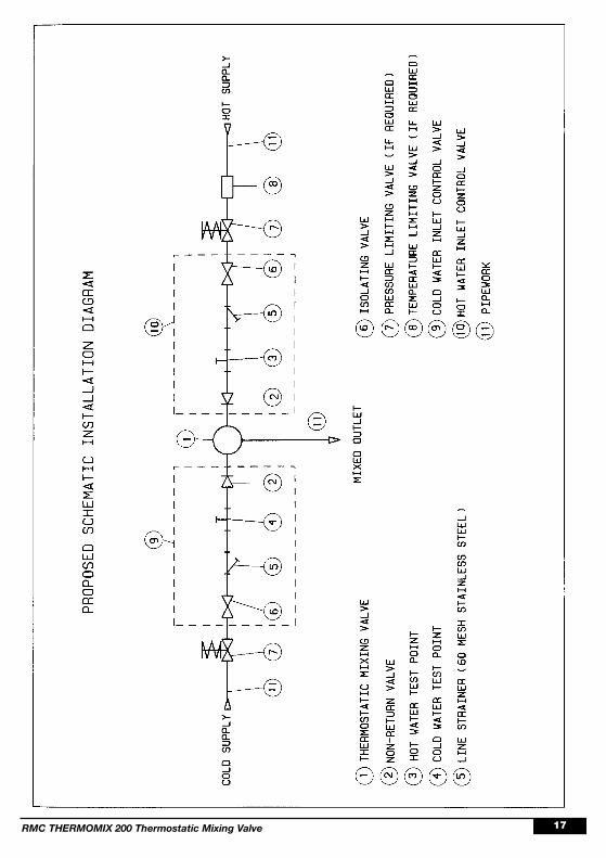
AS3500.4 requires that “Each thermostatic mixing valve shall havean isolating stop tap/valve, line strainer and cross-flow preventiondevice (non-return) valve fitted to the hot and cold water supplylines”. The inlet fittings supplied with each TMV will ensure thisrequirement is met. If the THERMOMIXTM 200 is to be installedwithout the supplied inlet control valves then it will be necessary toinstall isolating and non-return valves and strainer to both inlets tothe valve. Strainers must be fitted to prevent any particulatecontamination from entering the valve. These strainers should be 60Mesh stainless steel. Isolating valves are required so that the watersupply to the valve can be isolated if servicing is required.
Ensure that the test plugs in the top of the inlet fittings are tight. The4mm Allen key for adjusting the temperature can also be used totighten the test plug.
The valve should be installed so it can be accessed easily formaintenance or servicing. The pipework to and from the valvemust not be used to support the weight of the valve. Rathersaddle clips or pipe support brackets must be used to mount theinlet control valves and TMV firmly to a wall or rigid supportstructure. If the inlet control valves are not used then a suitablesupport bracket or saddle is required to support the weight of thevalve. This is to ensure the pipework is not under load from thevalve.
The mixing valve can be installed in a wall cavity, under a basin oron a wall, however it is essential that the mixing valve and inletfittings are easily accessible for servicing.
During installation or servicing, heat must not be applied near themixing valve and inlet fittings during installation or servicing asthis will damage the valve and inlet fittings internals. Failure tocomply with this requirement will damage the valve and fittings. Itwill put the user at risk, and it will void the warranty of the valve.
17RMC THERMOMIX 200 Thermostatic Mixing Valve

18 RMC THERMOMIX 200 Thermostatic Mixing Valve

19RMC THERMOMIX 200 Thermostatic Mixing Valve

20 RMC THERMOMIX 200 Thermostatic Mixing Valve
SHUT DOWN TEST
• Now that the mixing valve has been set and locked it isnecessary to perform a shut down check. Allow the mixed watertemperature to stabilise and note the outlet temperature. Whileholding a digital thermometer in the outlet flow, quickly isolatethe cold water supply to the valve. The outlet flow should quicklycease flowing. As a rule of thumb the flow should be less than0.1L/min following the isolation. Monitor the maximum outlet flowtemperature, and record this on the Commissioning Report(Appendix A). The temperature should not exceed that allowedby the applicable standard or code of practice for each state.Restore the cold water supply to the valve. After the mixed watertemperature has stabilised note the outlet temperature ensuringthe outlet temperature has re-established.
• Now repeat the above test, except this time quickly isolate thehot water supply to the valve. The outlet flow should quickly slowto a trickle. As a rule of thumb the trickle should typically be lessthan 0.4L/min@500kPa down to less than 0.1L/min@100kPafollowing the isolation. Restore the hot water supply to the valveand measure and record the outlet temperature after the mixedwater temperature has stabilised ensuring the outlet temperaturehas re-established.
• Ensure that all details of the Commissioning Report arecompleted and signed by the relevant signatories. A copy of thisreport should be kept with the installer and owner of thepremises.
• The valve is now commissioned and it can be used within thetechnical limits of operation.

21RMC THERMOMIX 200 Thermostatic Mixing Valve

22 RMC THERMOMIX 200 Thermostatic Mixing Valve
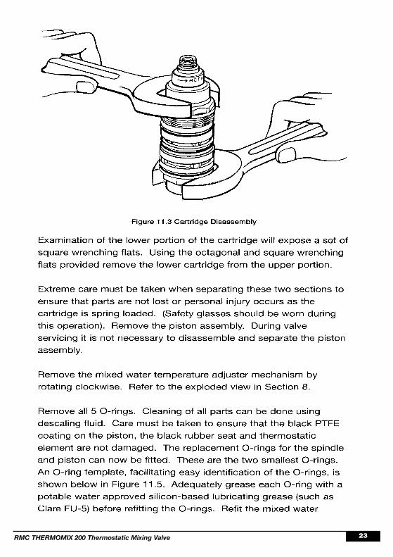
23RMC THERMOMIX 200 Thermostatic Mixing Valve
24 RMC THERMOMIX 200 Thermostatic Mixing Valve

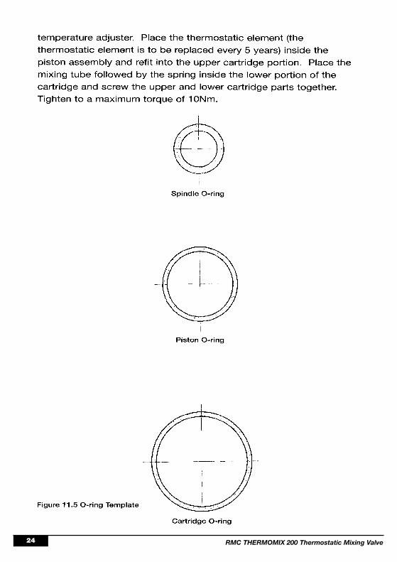
25RMC THERMOMIX 200 Thermostatic Mixing Valve
The 3 cartridge O-rings can now be fitted, making sure that they areadequately greased with a potable water approved silicon-basedlubricating grease (such as Clare FU-5) on each O-ring. Thecartridge can then be refitted back into the body and tightened to amaximum torque of 10Nm.
Check that the test plugs in the top of the inlet fittings are tight andthat there is no evidence of water leakage.
The valve must then be recommissioned as per Section 10 includingtemperature adjustment and the shut down test.

26 RMC THERMOMIX 200 Thermostatic Mixing Valve

27RMC THERMOMIX 200 Thermostatic Mixing Valve

28 RMC THERMOMIX 200 Thermostatic Mixing Valve

Reliance Manufacturing Company40-42 Ross Street, Newstead, Brisbane 4006, Australia.
P.O. Box 305, Fortitude Valley 4006.Ph: (07) 3252 3646Fax: (07) 3252 9391
STATE OFFICES
Reliance Manufacturing Company (N.Z.) Ltd.9 Newton Street, Mount Maunganui, New Zealand.
P.O. Box 4027, Mount Maunganui South.Ph: (07) 575 6639Fax: (07) 575 7221
SALES & TECHNICAL ADVICE
AustraliaPh: 1800 810 803Fax: 1800 062 669
New South Wales48 Percy StreetAuburn 2144Ph: (02) 9749 4422Fax: (02) 9749 4411
Victoria145 Heidelberg RoadNorthcote 3070Ph: (03) 9489 8966Fax: (03) 9489 8977
Western AustraliaU13A/2 Powell StreetOsborne Park 6017Ph: (08) 9443 4788Fax: (08) 9443 4799
New ZealandPh: 0800 800 523
Fax: 0800 101 503