manual de instrucciones instruction manual manuel … · en-60204/1 electrical equipment of the...
TRANSCRIPT

Mérand Mécapâte Z.I. de la Turbanière. Brécé - BP 93329 35 533 Noyal-sur-Vilaine. FRANCE Web: www.merand.fr
MANUAL DE INSTRUCCIONES
INSTRUCTION MANUAL
MANUEL D’INSTRUCTION
AQUAPAN 100

Page 2
INDICE/ INDEX/ TABLE DES MATERIES
1. DECLARACIÓN "CE" DE CONFORMIDAD SOBRE MÁQUINAS (SEGÚN LA DIRECTIVA 89/392/CEE, ANEXO II SUB A) .................................................................................................................................5
2. DECLARATION "CE" OF APROVAL ABAUT MACHINES (ACCORDING TO THE DIRECTIVE 89/392/CEE, ATTACHED DOCUMENT II SUB A) ................................................................................................6
3. DECLARATION "CE" DE CONFORMITÉ (SELON LA NORMATIVE 89/392/CEE, ANEX II SUB A) 7
4. INSTRUCCIONES PARA LA PUESTA EN MARCHA FUNCIONAMIENTO Y MANTENIMIENTO DE LA MÁQUINA:......................................................................................................................................................8
5. DESCRIPCIÓN ..................................................................................................................................................9
6. INSTALACIÓN Y ALMACENAMIENTO DE LA MÁQUINA..................................................................10
6.1. INSTALACIÓN Y PUESTA EN SERVICIO DE LA MÁQUINA ...........................................................106.2. ALMACENAMIENTO DE LA MÁQUINA.............................................................................................10
7. REGULACIÓN Y AJUSTES MECÁNICOS.................................................................................................11
7.1. CINTA ENTRADA...................................................................................................................................11TENSADO DE LA BANDA TRANSPORTADORA..............................................................................................11
CENTRADO DE LA BANDA TRANSPORTADORA ..........................................................................................11
7.2. CORTADOR LONGITUDINAL ..............................................................................................................12CAMBIO EJE CORTADOR................................................................................................................................12
AJUSTE MEDIDA ENTRE CUCHILLAS ...........................................................................................................12
7.4. GUILLOTINA PNEUMÁTICA .....................................................................................................................13CAMBIO DE MATRIZ ........................................................................................................................................13
REGULACION CORTE MATRIZ .......................................................................................................................13
7.5. CINTA SALIDA .......................................................................................................................................14TENSADO DE LA BANDA TRANSPORTADORA..............................................................................................14
CENTRADO DE LA BANDA TRANSPORTADORA ..........................................................................................14
8. AJUSTE GUIAS MASA ENTRADA. .............................................................................................................15
9. UTILIZACIÓN DE LA MÁQUINA ...............................................................................................................16
9.1. DESCRIPCIÓN DE LOS MANDOS ........................................................................................................169.2. CONSOLA PROGRAMACION. ..............................................................................................................17
MENU SELECCION PROGRAMA.....................................................................................................................18
MENU MARCHA/PARO GRUPOS ....................................................................................................................19
MENU SELECCION PARAMETROS.................................................................................................................20
10. LIMPIEZA Y MANTENIMIENTO................................................................................................................21
10.1. LIMPIEZA DE LA MÁQUINA ................................................................................................................2110.2. PLEGADO DE LAS MESAS....................................................................................................................2110.4. ALMACENAMIENTO ACCESORIOS ...................................................................................................2210.5. MANTENIMIENTO.................................................................................................................................23
11. ELEMENTOS DE SEGURIDAD....................................................................................................................24
12. RECOMENDACIONES RELATIVAS A LA SEGURIDAD DE CUMPLIMIENTO OBLIGATORIO .26

Page 3
13. INSTRUCTIONS FOR THE INSTALLER AND MAINENANCE OF THE MACHINE: .......................28
14. DESCRIPTION.................................................................................................................................................29
15. INSTALATION AND STORAGE OF THE MACHINE..............................................................................30
15.1. INSTALATION AND STARTING THE MACHINE..............................................................................3015.2. STORAGE OF THE MACHINE ..............................................................................................................30
16. MECHANICAL ADJUSTMENT AND SETTINGS .....................................................................................31
16.1. ENTRANCE BAND .................................................................................................................................31TIGHTNING OF THE TRANSPORTATION BAND ...........................................................................................31
CENTRING THE TRANSPORTATION BAND ...................................................................................................31
16.2. LONGITUDINAL SLICER ......................................................................................................................32CHANGE OF THE AXIS SLICER ......................................................................................................................32
ADJUST BETWEEN BLADES ............................................................................................................................32
16.3. PNEUMATIC GUILLOTINE...................................................................................................................33CHANGE OF THE MOULD ..............................................................................................................................33
REGULATION SLICE MOULD .........................................................................................................................33
16.4. EXIT BAND .............................................................................................................................................34TIGHTING OF THE TRANSPORTATION BAND..............................................................................................34
CENTRING OF THE TRANSPORTATION BAND.............................................................................................34
17. ADJUSTEMENT TO THE GUIDES OF DOUGH .......................................................................................35
18. USE OF THE MACHINE ................................................................................................................................36
18.1. DESCRIPTION OF THE CONTROLS ....................................................................................................3618.2. PROGRAMMING CONSOLE. ................................................................................................................37
MENU SELECTION PROGARAM .....................................................................................................................38
MENU START/STOP GROUPS..........................................................................................................................39
MENU SELECTION PARAMETERS..................................................................................................................40
19. CLEANING AND MAINENANCE ................................................................................................................41
19.1. CLEANING OF THE MACHINE ............................................................................................................4119.2. TO FOLD THE TABLES .........................................................................................................................4119.3. STORAGE OF THE EQUIPEMENT .......................................................................................................4219.4. MAINTENANCE......................................................................................................................................42
20. SECURITY ELEMENTS.................................................................................................................................44
21. RELATIVE RECOMMENDATIONS OF SECURITY AND OBLIGATION COMPIANCE .................46

Page 4
22. INSTRUCTIONS POUR LE MISE A SERVICE ET MANTENANCE DU:..............................................48
23. DESCRIPTION.................................................................................................................................................49
24. INSTALLATION DE STOCKAGE ET DE LA MACHINE........................................................................50
24.1. INSTALLATION ET MISE EN SERVICE..............................................................................................5024.2. STOCKAGE DE LA MACHINNE...........................................................................................................50
25. RÉGULATION ET AJUSTEMENTS MÉCANIQUES ................................................................................51
25.1. CONVOYEUR D’ENTRÉE .....................................................................................................................51TENSION DE LES CONVOYEURS....................................................................................................................51
CENTRE DE LE CONVOYEUR .........................................................................................................................51
25.2. COUPEUR LONGEUR ............................................................................................................................52CHANGE AXE COUPEUR.................................................................................................................................52
AJUSTEMENT MESURE COUPERETS ............................................................................................................52
25.3. GUILLOTINE PNEUMATIQUE .............................................................................................................53CHANGER LA MATRICE...................................................................................................................................53
AJUSTEMENT DE LA MATRICE ......................................................................................................................53
25.4. CONVOYEUR DE SORTIE.....................................................................................................................54TENSION DE LE CONVOYEUR........................................................................................................................54
CENTRE DE LE CONVOYEUR .........................................................................................................................54
26. ADJUSTEMENT GUIDES ENTREE PATE .................................................................................................55
26.1. DESCRIPTION DES COMMANDES......................................................................................................5626.2. CONSOLE DE PROGRAMMATION......................................................................................................57
MENU SELECTION PROGRAMME..................................................................................................................58
MENU SELECTION DE PARAMETRES............................................................................................................60
27. NETTOYAGE ET ENTRETIEN ....................................................................................................................61
27.1. NETTOYAGE DE LA MACHINE...........................................................................................................6127.2. TABLES PLIANTES................................................................................................................................6127.4. STOCKAGE DES ACCESSOIRES..........................................................................................................6227.5. ENTRETIEN.............................................................................................................................................63
28. CARACTERISTIQUES DE SECURITE .......................................................................................................64
29. RECOMMANDATIONS CONCERNANT LA SÉCURITÉ DE LA CONFORMITÉ EXIGÉE ..............66
30. ELECTRIC PLANS/ SCHEMAS ELECTRIQUES ......................................................................................69
31. SPARE LIST/ LISTE DES PIÈCES ...............................................................................................................76

Page 5
1. DECLARACIÓN "CE" DE CONFORMIDAD SOBRE MÁQUINAS (SEGÚN LA DIRECTIVA 89/392/CEE, ANEXO II SUB A)
MERAND Mécapâte SAS ZI de la Turbanière - Brece - BP 93329 35533 Noyal on Vilaine – France
DECLARAMOS bajo nuestra única responsabilidad que la máquina: AQUAPAN 100 TIPO: AQUAPAN 100 Nº SERIE: AÑO DE CONSTRUCCIÓN: 2012
Se adapta a las normas armonizadas o documentos normativos: EN-292-1 Seguridad de máquinas. Conceptos básicos, principios generales para el diseño. EN-292-2 Seguridad de máquinas. Conceptos básicos, principios generales para el diseño. EN-60204/1 Equipo eléctrico de las máquinas industriales. EN-418 Seguridad de máquinas: Equipo de parada de emergencia. Aspectos funcionales. Principios para el diseño. Y es conforme a los requisitos esenciales de las Directivas: 89/392/CEE de "Seguridad de máquinas" 91/368/CEE de "Seguridad de máquinas" (modificación) 93/44/CEE de "Seguridad de máquinas" (modificación) 93/68/CEE de "Marcaje CE" (modificación) 73/23/CEE de "Seguridad del material eléctrico"
Noyal on Vilaine a 19 de Enero de 2012 Firmado:

Page 6
2. DECLARATION "CE" OF APROVAL ABAUT MACHINES (ACCORDING TO THE
DIRECTIVE 89/392/CEE, ATTACHED DOCUMENT II SUB A) MERAND Mécapâte SAS ZI de la Turbanière - Brece - BP 93329 35533 Noyal on Vilaine – France
WE DECLARE under our only responsibility that the machine: CIABATTA SERIE 100 TYPE: AQUAPAN 100 Nº SERIE: YEAR OF CONSTRUCTION: 2012
It adapts to the normative documents: EN-292-1 Security of the machine. Basic concepts, principles for the design. EN-292-2 Security of the machine. Basic concepts, principles for the design. EN-60204/1 electrical equipment of the industrial machines. EN-418 security of machines: equipment for the stop emergency. Functional aspects. Principals for the design. And its in conformity with the essential requirement of the Directives: 89/392/CEE de "Security of machines" 91/368/CEE de "Security of machines" (modification) 93/44/CEE de "Security of machines" (modification) 93/68/CEE de "Cover CE" (modification) 73/23/CEE de "Security of the electric material"
Noyal on Vilaine January 19, 2012 Signed:

Page 7
3. DECLARATION "CE" DE CONFORMITÉ (SELON LA NORMATIVE 89/392/CEE, ANEX
II SUB A)
NOUS DÉCLARONS sous notre responsabilité que la machine:
AQUAPAN100 TYPE: AQUAPAN 100 Nº SÉRIE: ANNÉE DE CONSTRUTION: 2012
Il s'adapte aux normes harmonisées ou les documents normatifs: EN-292-1 Sécurité des machines. Concepts basiques, des principes généraux pour le dessin. EN-292-2 Sécurité des machines. Concepts basiques, des principes généraux pour le dessin. EN-60204/1 Équipament électrique des machines industrielles. EN-418 Securité des machines: Équipament d’arrêt d’urgence. Aspects fonctionnels. Principes pour le dessin. Et est conforme aux conditions requises essentielles des Comités directeurs : 89/392/CEE du "Securité des machines" 91/368/CEE du "Securité des machines" (modification) 93/44/CEE du "Securité des machines" (modification) 93/68/CEE du "Marqué CE" (modification) 73/23/CEE du "Securité du matériel électrique"
Noyal sur vilaine, a 19 janvier 2012 Signé:

Page 8
4. INSTRUCCIONES PARA LA PUESTA EN MARCHA FUNCIONAMIENTO Y MANTENIMIENTO DE LA MÁQUINA:
CIABATTERA AQUAPAN 100 NOTA IMPORTANTE: LEER ESTE MANUAL ANTES DE PONER LA MÁQUINA EN SERVICIO. CONSERVAR PARA FUTUROS USOS.
1. CARACTERÍSTICAS TÉCNICAS
DIMENSIONES (Largo x ancho x alto) 4 x 135 x1,5m. ALTURA DE TRABAJO 985 mm ANCHO TRABAJO 600mm TENSIÓN DE ALIMENTACIÓN 380V III+N+GND INTENSIDAD NOMINAL 2,7A POTENCIA TOTAL 1,5Kw ALIMENTACIÓN NEUMÁTICA Aire comprimido, seco y filtrado PRESIÓN DE SERVICIO 5 a 7 bar CONSUMO AIRE (a 6 bar) 50 l/min TEMPERATURA SERVICIO +5 a +40ºC TEMPERATURA DE ALMACENAMIENTO -25 a +55ºC GRADO DE HUMEDAD ADMISIBLE 30% a 95% NIVEL AUDITIVO <70 dB
Page 9
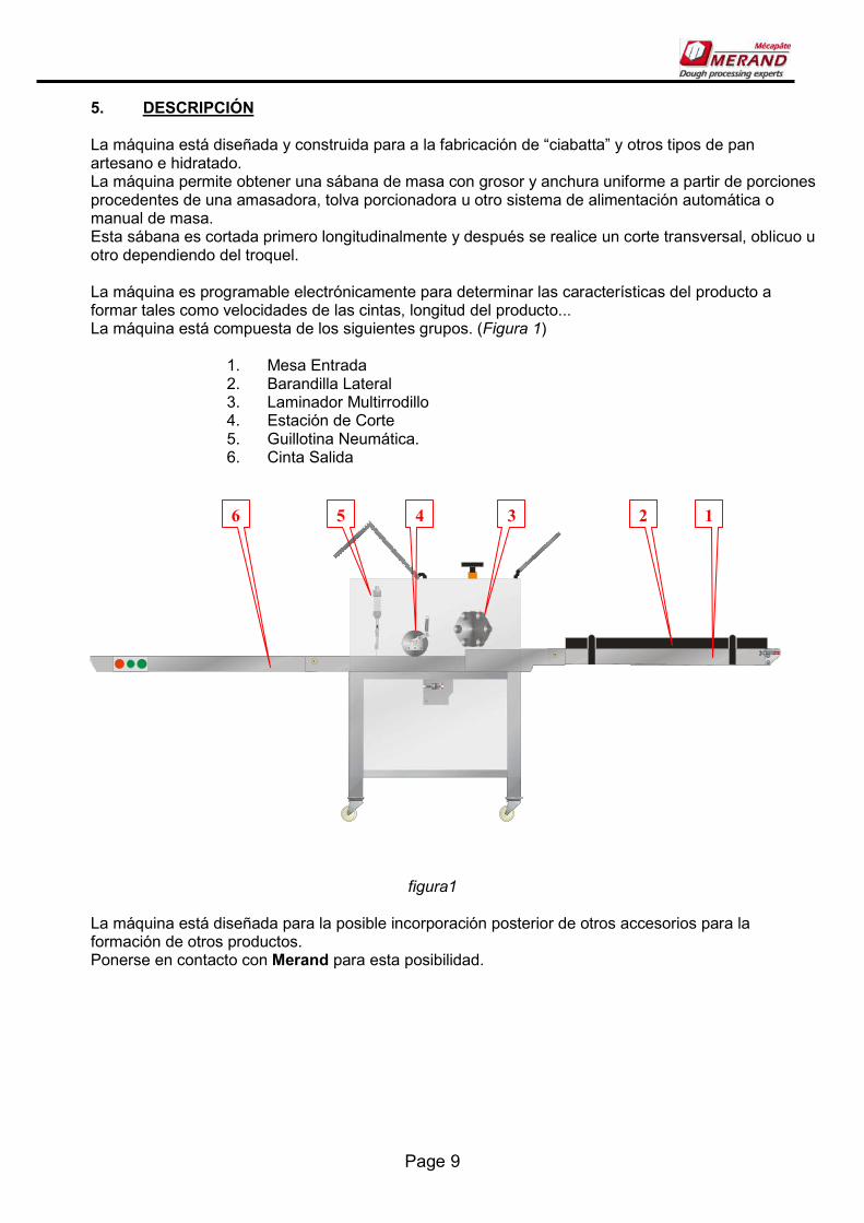
5. DESCRIPCIÓN La máquina está diseñada y construida para a la fabricación de “ciabatta” y otros tipos de pan artesano e hidratado. La máquina permite obtener una sábana de masa con grosor y anchura uniforme a partir de porciones procedentes de una amasadora, tolva porcionadora u otro sistema de alimentación automática o manual de masa. Esta sábana es cortada primero longitudinalmente y después se realice un corte transversal, oblicuo u otro dependiendo del troquel. La máquina es programable electrónicamente para determinar las características del producto a formar tales como velocidades de las cintas, longitud del producto... La máquina está compuesta de los siguientes grupos. (Figura 1)
1. Mesa Entrada 2. Barandilla Lateral 3. Laminador Multirrodillo 4. Estación de Corte 5. Guillotina Neumática. 6. Cinta Salida
figura1 La máquina está diseñada para la posible incorporación posterior de otros accesorios para la formación de otros productos. Ponerse en contacto con Merand para esta posibilidad.
1 2 3 4 5 6
Page 10
6. INSTALACIÓN Y ALMACENAMIENTO DE LA MÁQUINA
6.1. INSTALACIÓN Y PUESTA EN SERVICIO DE LA MÁQUINA La instalación y puesta en servicio de la máquina será efectuada por el servicio técnico de Merand o por personal autorizado. En caso de traslado de la máquina, las máquinas serán siempre trasladadas levantándolas con una pluma, con una carretilla elevadora ó sobre carros de transporte. ¡No trasladar nunca la máquina arrastrándola por las lapas de apoyo! Situar la máquina perfectamente alineada y nivelada, mediante las lapas de apoyo regables. La conexión eléctrica general de la máquina se hará en el regletero dispuesto para tal fin en el cuadro eléctrico marcado GND N R S T con una manguera de 5 x 2.5mm. Para más detalles ver esquema eléctrico.
6.2. ALMACENAMIENTO DE LA MÁQUINA En caso de tener que permanecer la máquina fuera de uso durante un tiempo prolongado es importante observar las siguientes recomendaciones:
- Limpiar perfectamente la máquina de restos de masa, harina ó azúcar. - Guardar en un sitio sin humedad ni temperaturas extremas. - Cubrir la máquina con tela ó plástico para protegerla del polvo y suciedad. - Apoyar por las lapas en su posición más baja, procurando que quede perfectamente estable. - Desconectar la alimentación eléctrica
- No dejar ninguna matriz colocada en la guillotina. - Proteger las matrices con una ligera capa de aceite SAE 40

Page 11
7. REGULACIÓN Y AJUSTES MECÁNICOS La máquina viene ajustada de fábrica o en su puesta en servicio por el personal técnico. No obstante existen algunos ajustes que se pueden efectuar posteriormente si variaran las condiciones de uso. A continuación se detallan dichos ajustes grupo a grupo.
7.1. CINTA ENTRADA
TENSADO DE LA BANDA TRANSPORTADORA
La banda transportadora de la cinta de alimentación puede ser tensada ó aflojada si las lonas patinaran sobre los rodillos ó quedaran frenadas. Para ello actuaremos sobre los tornillos tensores A (figura 1) dispuestos a ambos lados de la máquina. Aflojaremos la tuerca B y mediante el tornillo tensaremos ó aflojaremos la lona siempre uniformemente a ambos lados. Volver a apretar siempre la tuerca B una vez acabada la operación de tensado.
figura 1 Importante: No es conveniente dejar la banda excesivamente tensa.
CENTRADO DE LA BANDA TRANSPORTADORA Si la banda tuviera tendencia a desplazarse lateralmente sobre los rodillos, se procederá a su centrado de la siguiente forma: Tensar lentamente la banda transportadora solo del lado hacia donde se desplace hasta que se observe que empieza a desplazarse hacia el lado contrario. En este momento destensar ligeramente de ese mismo lado, hasta que observemos que se mantiene centrada. Repetir el proceso si fuera necesario. El proceso de centrado de lonas es lento y requiere tener paciencia.
A
B

Page 12
7.2. CORTADOR LONGITUDINAL
CAMBIO EJE CORTADOR Para cambiar de producto es necesario cambiar el eje de cuchillas de corte longitudinal. El procedimiento es el siguiente: -Liberar el gancho que sujeta la guillotina y subirla hacia arriba para poder acceder con comodidad al eje de corte. Levantar las palancas (A figura 2) hasta que los extremos del eje de cuchillas salgan de la fijación lateral. - Tenemos ahora los rodillos libres para poderlos retirar, y sustituir por otro eje para un nuevo producto. - El proceso de montaje es el mismo a la inversa.
figura 2
AJUSTE MEDIDA ENTRE CUCHILLAS
Liberar las cuchillas del eje aflojando los tornillos prisioneros A (figura 3). Mover las cuchillas a su nueva posición, volver a apretar los tornillos prisioneros. IMPORTANTE: Efectuar esta operación con el eje cuchillas fuera de la estación de corte.
figura 3
A
A
Page 13
7.3.
7.4. GUILLOTINA PNEUMÁTICA CAMBIO DE MATRIZ
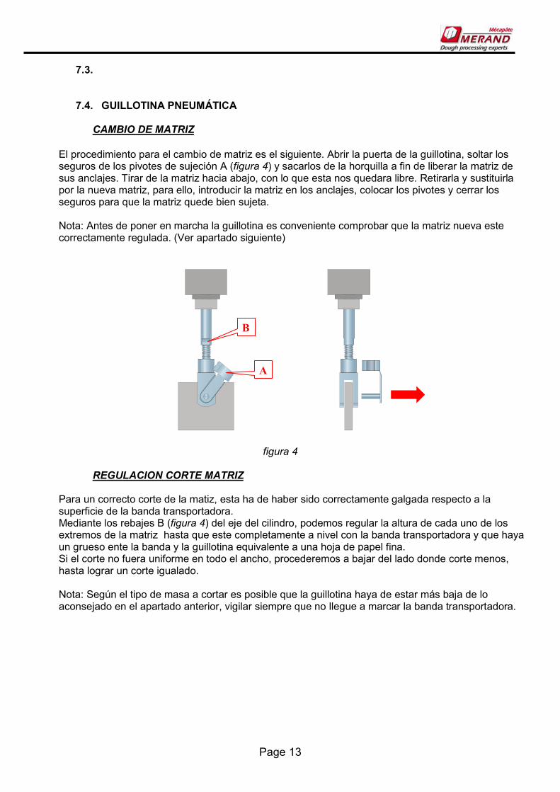
El procedimiento para el cambio de matriz es el siguiente. Abrir la puerta de la guillotina, soltar los seguros de los pivotes de sujeción A (figura 4) y sacarlos de la horquilla a fin de liberar la matriz de sus anclajes. Tirar de la matriz hacia abajo, con lo que esta nos quedara libre. Retirarla y sustituirla por la nueva matriz, para ello, introducir la matriz en los anclajes, colocar los pivotes y cerrar los seguros para que la matriz quede bien sujeta. Nota: Antes de poner en marcha la guillotina es conveniente comprobar que la matriz nueva este correctamente regulada. (Ver apartado siguiente)
figura 4
REGULACION CORTE MATRIZ Para un correcto corte de la matiz, esta ha de haber sido correctamente galgada respecto a la superficie de la banda transportadora. Mediante los rebajes B (figura 4) del eje del cilindro, podemos regular la altura de cada uno de los extremos de la matriz hasta que este completamente a nivel con la banda transportadora y que haya un grueso ente la banda y la guillotina equivalente a una hoja de papel fina. Si el corte no fuera uniforme en todo el ancho, procederemos a bajar del lado donde corte menos, hasta lograr un corte igualado. Nota: Según el tipo de masa a cortar es posible que la guillotina haya de estar más baja de lo aconsejado en el apartado anterior, vigilar siempre que no llegue a marcar la banda transportadora.
A
B

Page 14
7.5. CINTA SALIDA TENSADO DE LA BANDA TRANSPORTADORA
La banda transportadora de la cinta de la salida de la guillotina puede ser tensada ó aflojada si las lonas patinaran sobre los rodillos ó quedaran frenadas. Para ello sacar la tapa lateral y actuar sobre los tornillos tensores A (figura 5) dispuestos a ambos lados de la máquina, por la parte interior del lateral de la cinta.. Aflojaremos la tuerca B y mediante el tornillo tensaremos ó aflojaremos la lona siempre uniformemente a ambos lados. Volver a apretar siempre la tuerca B una vez acabada la operación de tensado.
figura 5 Importante: No es conveniente dejar la banda excesivamente tensa.
CENTRADO DE LA BANDA TRANSPORTADORA
Si la banda tuviera tendencia a desplazarse lateralmente sobre los rodillos, se procederá a su centrado de la siguiente forma: Tensar lentamente la banda transportadora solo del lado hacia donde se desplace hasta que se observe que empieza a desplazarse hacia el lado contrario. En este momento destensar ligeramente de ese mismo lado, hasta que observemos que se mantiene centrada. Repetir el proceso si fuera necesario. El proceso de centrado de lonas es lento y requiere tener paciencia.
A
B

Page 15
8. AJUSTE GUIAS MASA ENTRADA. Para ajustar el ancho de las guías de ancho de la masa a la entrada, proceder de la siguiente forma:
figura 6 Primeramente aflojar las dos manetas A, (figura 6) y girar la barandilla hacia delante hasta el tope. Volver a apretar las manetas. Aflojar los dos pomos B y deslizar la guía hasta la medida deseada. Reapretar pomos B. Hacer lo mismo al otro lado.

Page 16
9. UTILIZACIÓN DE LA MÁQUINA
9.1. DESCRIPCIÓN DE LOS MANDOS Para la puesta en tensión de la máquina es necesario accionar el interruptor principal A (figura 7) situado en el cuadro de mandos en el lateral de la máquina. Se iluminará entonces el pulsador de rearme, al pulsarlo la máquina esta dispuesta para funcionar.
figura 7 El manejo de la máquina se efectúa desde el cuadro de mando, situado en la botonera sobre la mesa Los mandos son los siguientes: B Pulsador de emergencia: Provoca la parada de emergencia de la máquina. Para volver a poner la máquina en servicio es necesario desenclavarlo y volver a accionar el pulsador de rearme. C Pulsador de rearme: Para rearmar la máquina después de una parada. D Pulsadores de marcha/paro: Para poner en marcha ó parar la máquina. También se ha instalado una botonera de macha/paro al final de la cinta de salida para facilitar la recogida del producto. E Pulsador guillotina: Situado en el lateral de la puerta de salida de la máquina. Sirve para iniciar el contador de longitud de corte de la guillotina. Al apretar el pulsador la guillotina efectúa un corte y empieza a contar la longitud especificada en el parámetro longitud corte. F Consola de programación: Acceso para introducir y modificar los parámetros y velocidades para los distintos tipos de productos que puede hacer la máquina y para poner en marcha los distintos grupos de la máquina.
A
C D
B F

Page 17
9.2. CONSOLA PROGRAMACION. Al dar tensión a la máquina aparecerá en la consola de programación la siguiente pantalla:
En la parte inferior de la misma encontramos unos iconos que nos dan acceso a las distintas funciones de la consola. VELOCIDAD GENERAL: Para modificar en una sola operación todas las velocidades d la máquina. Expresada en % de la velocidad máxima. 100 es el máximo. MENÚ SELECCIÓN PROGRAMA: Accede al menú de selección de programas. MENÚ MARCHA/PARO GRUPOS: Accede al menú de selección de marcha y paro de los distintos grupos de la máquina. MENÚ SELECCIÓN PARAMETROS: Accede al menú de selección y modificación de los distintos parámetros de la máquina. MENU SELECCIÓN IDIOMA PANTALLA
A
B
C D E

Page 18
MENU SELECCION PROGRAMA Al presionar sobre el icono de SELECCIÓN DE PROGRAMA accederemos a la siguiente pantalla:
En ella encontramos el listado de programas y marcado el programa activo. Pulsando sobre el nombre de un programa A aparecerá un teclado alfanumérico que nos permite cambiar el nombre de dicho programa. Pulsando sobre el recuadro adyacente B, este cambiará de color indicando que este es el programa seleccionado. En la parte inferior, encontramos el icono de COPIAR PROGRAMA C, este menú nos permite copiar todos los parámetros de un programa sobre otro. Tener en cuenta que esta operación sobrescribirá los valores anteriores del programa destino.
A
B
C

Page 19
MENU MARCHA/PARO GRUPOS Para poner en marcha y parar los distintos grupos de la máquina pulsar el icono del MENU MARCHA PARO en el menú principal de la máquina. Aparecerá entonces la siguiente pantalla. Pulsando sobre cada uno de los grupos estos se pondrán verdes cuando el grupo este en marcha y permanecerán rojos cuando estén apagados.

Page 20
MENU SELECCION PARAMETROS Pulsando sobre el icono SELECCIÓN PARAMETROS del menú principal accedemos a la siguiente pantalla: En ella aparecen unos recuadros con el nombre de las distintas partes de la máquina. Pulsando sobre ellos podemos variar dichos parámetros de funcionamiento de las distintas partes. Los parámetros que pueden ser variados son los siguientes:
MESA ENTRADA: Indica la velocidad de la cinta de entrada a la calibradora. Expresa la frecuencia en HZ de funcionamiento del motor.. RODILLO CALIBRADOR: Indica la velocidad del multi- rodillo superior de la calibradora. Expresa la frecuencia en HZ de funcionamiento del motor. MESA SALIDA: Indica la velocidad de la cinta de salida de la guillotina. Expresa la frecuencia en HZ de funcionamiento del motor. LONGITUD CORTE: Indica la distancia en milímetros que avanzara la cinta transportadora entre cada corte de la guillotina. ALTURA CALIBRADOR: Indica el valor que debe marcar el indicador digital del multi-rodillo i expresa la altura de laminación de la máquina. Esta medida no tiene ningún efecto sobre los mecanismos de la máquina, debiéndose adaptar manualmente. SEPARACION PALAS: Indica el valor que marcan los regles de las guias de entrada. Esta medida no tiene ningún efecto sobre los mecanismos de la máquina, debiéndose adaptar manualmente.
Page 21
10. LIMPIEZA Y MANTENIMIENTO
10.1. LIMPIEZA DE LA MÁQUINA Después de cada uso ó al finalizar la jornada deberán efectuarse las siguientes operaciones de limpieza: 1. Retirar de la máquina y limpiar todos los accesorios usados: ejes cortadores, matriz de corte, etc.[ Dichos accesorios pueden lavarse con agua y jabón atóxico debiendo ser secados cuidadosamente una vez limpios. 2. Aspirar ó soplar todos los restos de harina y azúcar que estuvieran en la máquina. 3. Retirar cualquier resto de masa que se encontrara encima la mesa ó en algún rincón. 4. Limpiar las bandas transportadoras, primero con un cepillo para retirar el azúcar y la harina, luego con un trapo húmedo y jabón neutro atóxico. Hacer avanzar las lonas para limpiarlas en todo su recorrido. 5. Para la limpieza de las mesas y demás elementos de la estructura en inoxidable se recomienda usar algún producto específico para la limpieza de acero inoxidable. Periódicamente aspirar ó soplar la harina y el polvo que pudiera haberse introducido en el cuadro eléctrico.
10.2. PLEGADO DE LAS MESAS El plegado de las mesas sirve para que al guardar la maquina cuando no se utilice, ocupe el menor espacio posible Mesa entrada: Primeramente retirar hacia atrás las guías de masa. Para ello aflojar los dos pomos B (figura 6) y deslizar las guías hasta su mínima separación. Volver a apretar los pomos. Seguidamente aflojar las manetas A y girar las guías a su posición mas atrasada. Reapretar las manetas. Tirar del fijador de seguridad C y Plegar la mesa, hasta que sobrepase su posición vertical (Es posible que haya que hacerlo entre dos personas). El pasador de seguridad ha de encajar en su nueva posición. Para la mesa de salida proceder de la misma forma, no hay guias que retirar.

Page 22
10.3.
Figura 8
10.4. ALMACENAMIENTO ACCESORIOS Para guardar los accesorios de corte que no se utilicen la maquina dispone de un anaquel en su parte inferior a tal fin. Se puede abrir para acceder cómodamente desde el lado de mando de la máquina. Los rodillos de corte se ubican en los encajes de la parte frontal, los troqueles van colgados de la parte posterior.
C

Page 23
10.5. MANTENIMIENTO La máquina ha sido diseñada para que el nivel de mantenimiento normal sea bajo, colocándose en su mayor parte elementos engrasados de por vida ó tensores de cadena automáticos. Sin embargo existen unas pocas operaciones que junto con una buena limpieza de la máquina contribuirán a una vida más prolongada de la misma. En la calibradora: Engrasar mensualmente la cadena de transmisión, usar grasa lítica. Engrasar mensualmente las columnas roscadas de graduación. Revisar la tensión y el centrado de la lona semanalmente. En la mesa de trabajo Revisar semanalmente la tensión y el centrado de la lona. Purgar semanalmente el depósito del filtro de aire ó con más frecuencia si estuviera más de la mitad lleno de agua. Para purgar quitar el tapón A (figura 16).
figura 16 Todas las operaciones aquí detalladas deberán efectuarse con una periodicidad más corta de la indicada si las condiciones de servicio de la máquina así lo exigieran.
A

Page 24
11. ELEMENTOS DE SEGURIDAD La máquina dispone de tapas fijas que protegen los elementos móviles, transmisiones, correas, motores, cuadro eléctrico, y demás elementos que pudieran implicar un riesgo y cuya manipulación no es necesaria para el uso habitual de la máquina. Estas tapas están fijadas por tornillos allen siendo necesaria una llave adecuada para poderlas desmontar. Esta operación solo podrá efectuarla personal cualificado para las operaciones de mantenimiento y reparación, y siempre con la máquina parada y desconectada. Asimismo queda terminantemente prohibido poner la máquina en marcha sin las tapas colocadas y fijadas con sus tornillos. Dispone también de unos resguardos abatibles a la entrada y a la salida del calibrador y rodillos cortadores para facilitar las operaciones de alimentación de la máquina y limpieza. Estos resguardos disponen de unos microrruptores eléctricos que impiden la puesta en marcha de la máquina si están abiertos, y provocan la parada en caso de abrirse con la máquina en marcha. En estos casos aparecen en el display de la consola de programación los siguientes mensajes:
IMPORTANTE: Para poner nuevamente en marcha la máquina después de una parada de emergencia es necesario cerrar los microinterruptores abiertos y accionar el pulsador de rearme, para desactivar la alarma. IMPORTANTE: Vigilar que no haya ningún objeto: Herramientas, trapos, cepillos, etc.... encima de las bandas antes de ponerlas en marcha. La máquina dispone de varios paros de emergencia situados en ambos lado de la misma que provocan un paro total de la máquina, siendo necesario desenclavarlos y accionar pulsador de marcha para volver a ponerla en servicio. Si por algún motivo se interrumpiera el suministro de aire comprimido a la máquina, que provocaría el mal funcionamiento de algún grupo de la máquina esta también sufrirá una parada de emergencia indicando la consola el siguiente mensaje:

Page 25
Debiendo reanudar el suministro del mismo y desactivar la alarma para reiniciar la producción. Las distintas zonas de peligro de la máquina están debidamente indicadas con pictogramas. No retirar ó borrar dichas señales.
Page 26
12. RECOMENDACIONES RELATIVAS A LA SEGURIDAD DE CUMPLIMIENTO OBLIGATORIO
1- La CHAPATERA SERIE 100 MOD: CBU600 ha sido construida para la formación de productos variados de masa de pan hidratado y otras masas de panadería. Cualquier otro uso está prohibido. Los accidentes que resulten de una utilización no prevista por el constructor no le son imputables al mismo, siendo a cuenta y riesgo del usuario. 2- La máquina ha sido prevista para ser utilizada por personas adultas e instruidas por personal cualificado. Está prohibido su uso ó manipulación por menores. 3- El uso, mantenimiento y reparación de la máquina se hará según lo indicado en este manual. Toda intervención no descrita en el mismo deberá ser autorizada por Merand 4-Los trabajos sobre la parte eléctrica de la máquina solamente serán efectuados por personal cualificado y respetando las normas de seguridad establecidas 5- La retirada de los envolventes fijos solo se hará por personal cualificado y siempre con la máquina fuera de servicio, teniendo que ser colocados antes de ponerla en marcha. 6-Los dispositivos de seguridad no deben ser modificados ó anulados ni mecánica ni eléctricamente. 7- No poner las manos bajo las protecciones 8-Los trabajos de mantenimiento se harán con la máquina desconectada tanto eléctricamente como neumáticamente. 9-Cualquier pieza averiada solo será sustituida por un recambio original . 10-Está totalmente prohibido realizar cualquier modificación mecánica, eléctrica ó en el software sin el consentimiento del fabricante. Merand declina toda responsabilidad sobre cualquier situación provocada por el no cumplimiento de alguna de las anteriores recomendaciones.

Mérand Mécapâte Z.I. de la Turbanière. Brécé - BP 93329 35 533 Noyal-sur-Vilaine. FRANCE Web: www.merand.fr

Page 28
13. INSTRUCTIONS FOR THE INSTALLER AND MAINENANCE OF THE MACHINE:
CIABATTERA AQUAPAN 100
IMPORTANT NOTE: READ THIS MANUAL BEFORE USING THE MACHINE. KEEP THE MANUAL FOR FUTURE USING.
1. THECNICAL CHARACTERISTICS:
DIMENSIONS (Long x wide x high) 4 x 135 x1,5m. HEIGHT WORK 985 mm WIDE WORK 600mm FEED TENSION 380V III+N+GND NORMAL INTENSITY 2,7A TOTAL POWER 1,5 Kw PNEUMATIC FEED compressed air, Dry and filtered SERVISE PRESSURE 5 a 7 bar AIR CONSUMER (a 6 bar) 50 l/min SERVISE TEMPERATURE +5 a +40ºC STORAGE TEMPERATURE -25 a +55ºC DEGREE OF HUMIDITY ADMISSIBLE 30% a 95% AUDITORY LEVEL <70 dB
Page 29
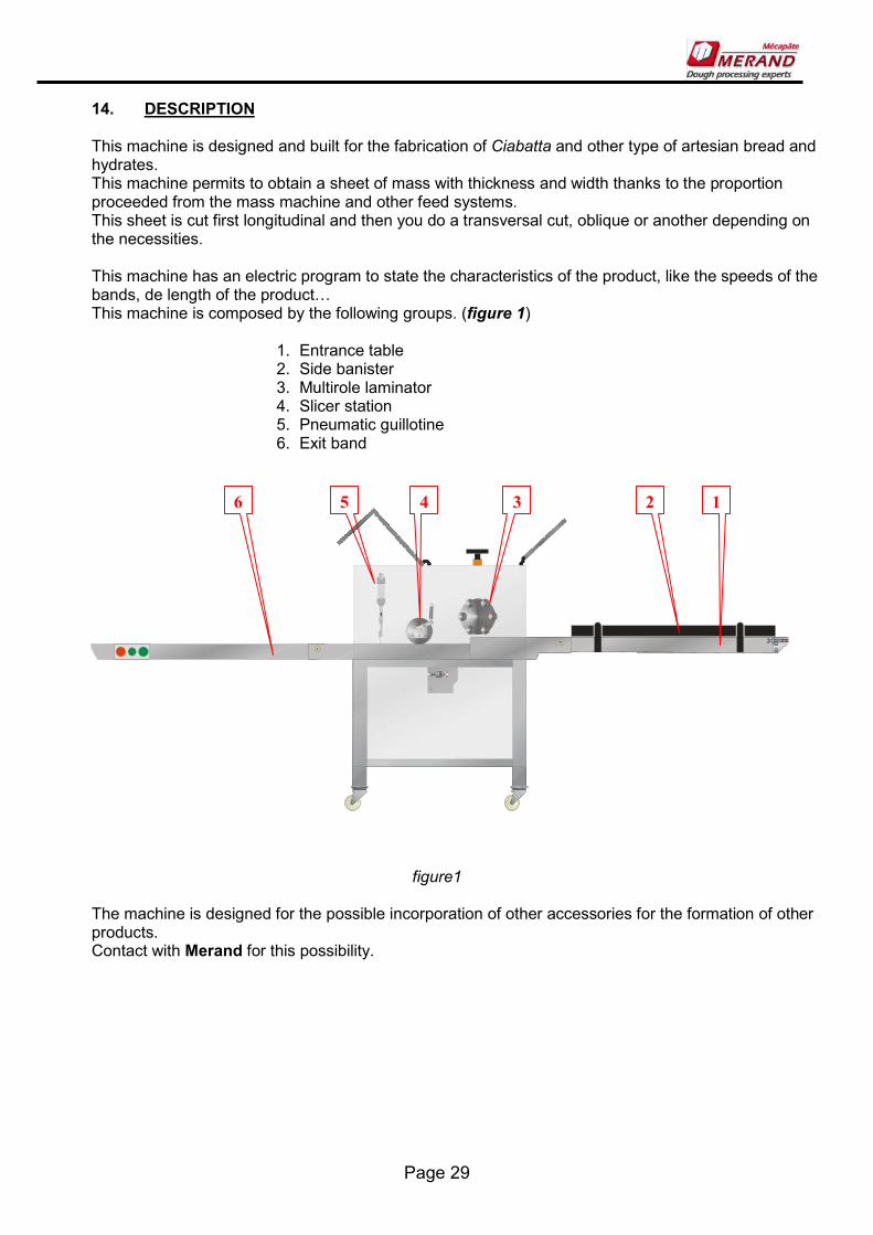
14. DESCRIPTION This machine is designed and built for the fabrication of Ciabatta and other type of artesian bread and hydrates. This machine permits to obtain a sheet of mass with thickness and width thanks to the proportion proceeded from the mass machine and other feed systems. This sheet is cut first longitudinal and then you do a transversal cut, oblique or another depending on the necessities. This machine has an electric program to state the characteristics of the product, like the speeds of the bands, de length of the product[ This machine is composed by the following groups. (figure 1)
1. Entrance table 2. Side banister 3. Multirole laminator 4. Slicer station 5. Pneumatic guillotine 6. Exit band
figure1 The machine is designed for the possible incorporation of other accessories for the formation of other products. Contact with Merand for this possibility.
1 2 3 4 5 6
Page 30
15. INSTALATION AND STORAGE OF THE MACHINE
15.1. INSTALATION AND STARTING THE MACHINE The installation and starting of the machine will be done by the service technicians of Merand or by personal authorized. In case the machine has to be moved, the machines will have to be lifted always by a lifting cart o transportation cart. Never drag the machine to move it! Situate the machine perfectly centred and levelled. The general electrical connection of the machine will be done at the terminal strip situated at the electric square marked GND N R S T with a hose of 5 x 2.5mm. For more details consult the electric diagram.
15.2. STORAGE OF THE MACHINE In case that the machine has to be a long time without use, it’s important to observe the following recommendations:
- Clean perfectly the machine of left over’s of mass or flower.
- Keep in a place without humidity or extreme temperatures
- Cover the machine with a plastic to protect it from dost and dirt.
- Disconnect de electrical feed.
- Don’t let any paced mould in the guillotine. - Protect the moulds with a light cap of oil SAE 40

Page 31
16. MECHANICAL ADJUSTMENT AND SETTINGS The machine is adjusted by fabric. But there can be some adjustments done alter if there is a change on the conditions of use. Following there are some details to see the different adjusts group a group.
16.1. ENTRANCE BAND
TIGHTNING OF THE TRANSPORTATION BAND
The sides of the transportation band can be tenses or loosened if the canvas slipped over the screws or they were slowing. For that, we’ll act on the tightening screws A (figure 1) situated on both sides of the machine. We’ll loosen nut B with the screw, tightening or loosening the canvas always the same way on both sides. Always tighten the nut B when you’ve finished the tense operation
figure 1 Important: it’s not convenient to leave the band to tight.
CENTRING THE TRANSPORTATION BAND If the band had any tendency to move sideways over the screws, you’ll have to do the centring the following way: Tense slowly the transportation band only on the side where it moves to until you see that its starts to move to the opposite side. At this moment loosen slightly at that same side, until you observe that it keeps centred. Repeat the process if its necessary. The process of centring the band is slow and you need patience.
A
B

Page 32
16.2. LONGITUDINAL SLICER
CHANGE OF THE AXIS SLICER To change the product it’s necessary to change de axis of the slicers of the longitudinal cut. The procedure is the following: - release the hook that subjects the guillotine and pull it up, like that you’ll manage to reach at the axis blade. - Lift the lever (A figure 2) until the extremes of the axis of the slicers come out of the side fixation. - Now we have the screws free so that we can take them off, or change them for another axis for a new product. - The process for assembly is the same but the opposite way
figure 2
ADJUST BETWEEN BLADES
Release the blades of the axis loosening the screws of the prisoner’s screws A (figure 3). Move the blades to their new position, and tighten again the prisoner’s screws. IMPORTANT: Execute this operation with the blades of the axis out of the cutting station.
figure 3
A
A
Page 33
16.3. PNEUMATIC GUILLOTINE
CHANGE OF THE MOULD
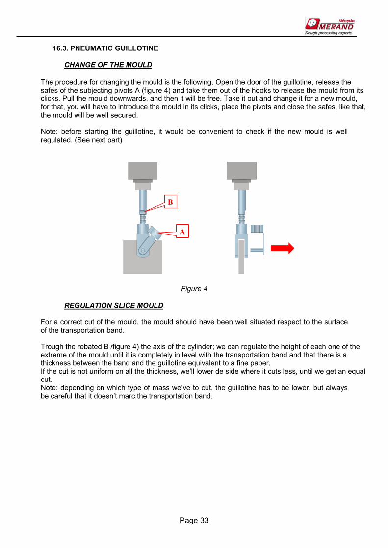
The procedure for changing the mould is the following. Open the door of the guillotine, release the safes of the subjecting pivots A (figure 4) and take them out of the hooks to release the mould from its clicks. Pull the mould downwards, and then it will be free. Take it out and change it for a new mould, for that, you will have to introduce the mould in its clicks, place the pivots and close the safes, like that, the mould will be well secured. Note: before starting the guillotine, it would be convenient to check if the new mould is well regulated. (See next part)
Figure 4
REGULATION SLICE MOULD For a correct cut of the mould, the mould should have been well situated respect to the surface of the transportation band. Trough the rebated B /figure 4) the axis of the cylinder; we can regulate the height of each one of the extreme of the mould until it is completely in level with the transportation band and that there is a thickness between the band and the guillotine equivalent to a fine paper. If the cut is not uniform on all the thickness, we’ll lower de side where it cuts less, until we get an equal cut. Note: depending on which type of mass we’ve to cut, the guillotine has to be lower, but always be careful that it doesn’t marc the transportation band.
A
B

Page 34
16.4. EXIT BAND
TIGHTING OF THE TRANSPORTATION BAND The transportation band of the exit band of the guillotine can be tenses or loosened if the canvas slipped over the screws or they were slowing. For that, we will take off the side lid and we’ll act on the tightening screws A (figure 5) situated on both sides of the machine, in the interior part of the side band. We’ll loosen nut B with the screw, tightening or loosening the canvas always the same way on both sides. Always tighten the nut B when you’ve finished the tense operation
figure 5 Important: it’s not convenient to leave the band to tight.
CENTRING OF THE TRANSPORTATION BAND If the band had any tendency to move sideways over the screws, you’ll have to do the centring the following way: Tense slowly the transportation band only on the side where it moves to until you see that its starts to move to the opposite side. At this moment loosen slightly at that same side, until you observe that it keeps centred. Repeat the process if it’s necessary. The process of centring the band is slow and you need patience.
A
B
Page 35
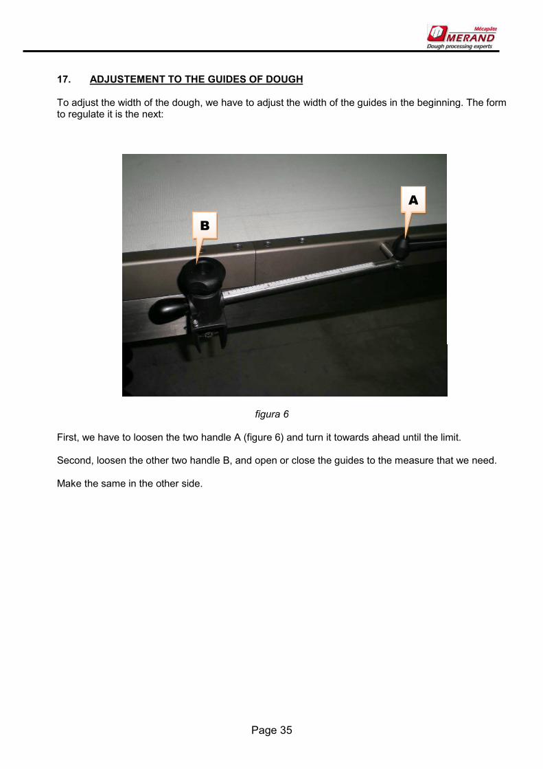
17. ADJUSTEMENT TO THE GUIDES OF DOUGH To adjust the width of the dough, we have to adjust the width of the guides in the beginning. The form to regulate it is the next:
figura 6 First, we have to loosen the two handle A (figure 6) and turn it towards ahead until the limit. Second, loosen the other two handle B, and open or close the guides to the measure that we need. Make the same in the other side.

Page 36
18. USE OF THE MACHINE
18.1. DESCRIPTION OF THE CONTROLS For the tension of the machine its necessary to press the principal switch A (figure 6) situated in the dashboard of the controls on the side of the machine. The button you press will lighten, and the machine will be ready to start working.
Figure 6 the use of the machine will be made from the dashboard of the controls, situated in the bottom on the table. The controls are the following: B Emergency switch: provokes the emergency stop of the machine. For starting the machine back again its necessary to knock out of its position and press again the button to start. C Switch for reset: it’s to reset the machine after a stop. D Switch of start/stop: to put on or off the machine. As well there is installed a button of on/off at the end of the band at the exit, to help the recollection of the product. E Guillotine switch: located al the side of the exit door of the machine. It is used for starting the counter of the length of cut of the guillotine. When you press the guillotine switch, it does a cut and its starts to count the length specified on the length cut parameter F Programming console: Access to introduce and modify the parameters and the speed for the different types of products that the machine can do and to start the different groups of the machine.
A
C D
B E

Page 37
18.2. PROGRAMMING CONSOLE. When you give voltage at the machine it will appear on the screen of the programming console:
On the inferior part of the screen you will find some icons that they’ll give you access to different functions of the console. GENERAL SPEED: It is used to modificate all the speeds of the machine. It is showed in % of the maximum speed. 100 is the maximum. SELECTION PROGRAM MENU: indicates the present program and it gives access to the selection program menu. MENU START/STOP GROUPS: Access at the menu start/stop to the different groups of the machine. MENU SELECTION PARAMETERS: Access to the menu of selection and modification of the different parameters of the machine. LANGUAGE SELECTION MENU SCREEN
E
A
B
C D

Page 38
MENU SELECTION PROGARAM When you press on top of the icon SELECTION PROGRAM you will access to the following screen:
On this screen we will find the list of programs and the program in use will be marked. Pressing on the name of a program A there will appear a alphanumeric keyboard that will permit us to change the name of its program. Pressing on the adjacent square B, this one will change colour indicating which the selected program is. On the inferior part, we will find a icon of COPY PROGRAM C, this menu will permit us to copy all the parameters of one program to another. Remember that this operation will change the values that the program had before.
A
B
C
Page 39
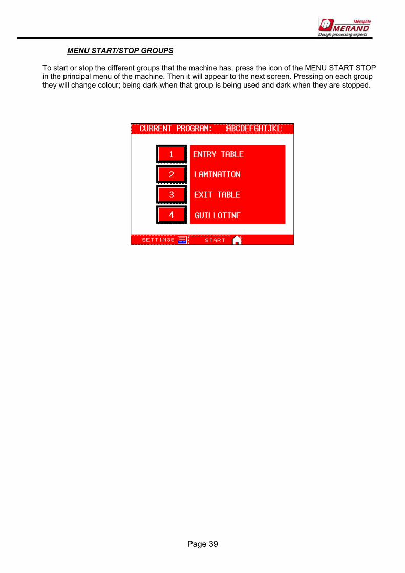
MENU START/STOP GROUPS To start or stop the different groups that the machine has, press the icon of the MENU START STOP in the principal menu of the machine. Then it will appear to the next screen. Pressing on each group they will change colour; being dark when that group is being used and dark when they are stopped.

Page 40
MENU SELECTION PARAMETERS Pressing the icon SELECTION PARAMETERS of the principal menu we will access to the following screen: On the screen there will appear some squares with the names of the different parts of the machine. Pressing on the values we can change the function parameters of the different parts. The parameters that you can change are the following:
ENTRY TABLE: Indicates the speed of the entrance table to the lamination. Expresses the lineal speed in in HZ the function of the engine, LAMINATION: Indicates the speed of the multi-roller above the lamination. The frequency is expressed in HZ the function of the engine. EXIT TABLE: Indicates the speed of the exit band of the guillotine. Expresses the lineal speed in HZ the function of the engine. CUT LENTH: Indicates the distance in millimeters that will wind on on the transporting band between each cut of the guillotine. HEIGHT ROLLER: Indicates the value that the digital indicator of the multi-roller should mark and it expresses the height of the lamination of the machine. This action hasn’t got any effect on the machine mechanisms, because you can adapt it manually. SPADES SEPARATION: Indicates the value that marks the rules of the guides of the beginning. This action hasn’t got any effect on the machine mechanisms, because you can adapt it manually.
Page 41
19. CLEANING AND MAINENANCE
19.1. CLEANING OF THE MACHINE After each use or after a full time work you should do the following cleaning operations: 1. Realize de machine and clean all the used accessories: Blades, mould of cut[ these accessories can be cleaned with water and soap, but having to by dry after been cleaned. 2. Hover or blow at all the left over’s of flower in the machine. 3. Throw any rest of mass that is left over. 4. Clean the transportation bands, first with a brush to take out the sugar and the flower, after with a humid cloth with soap. Make the lone advance to clean all its way and clean underneath the lone. 5. To clean the table and the other elements of the stainless structure its recommended to use a specific product to clean stainless steel. 6. Often hover or blow the flower and the dust that could have gone in the electric dashboard.
19.2. TO FOLD THE TABLES The fold of the tables is used to reduce the space that occupies the machine when it is not used. Table of entry: First, we have to withdraw backward the guides of the dough. To make this, we have to loosen the two handle B (figure 6) and move the guides to the minimum separation. Press again the two handle. Then, you have to loosen the handle A, and turn the guides to the most backward position. Press the handle. Throw out the security system C and fold the table, until arrive to the vertical position. (Maybe it will be done for two persons). The security system has to be positioned in its new position. To the exit table make the same. There are guides to retire.

Page 42
Figure 8
19.3. STORAGE OF THE EQUIPEMENT To store the accessories of cutting wish will be not used with the machine; it has an ironworks in the lower part. You can open this ironworks in the lower part. You can open this ironworks from the control panel side. The rollers for cutting are located in the lacer of the front part, the moulders are located in the posterior part.
19.4. MAINTENANCE The machine has been designed for a low normal maintenance, putting in nearly all of the parts lifelong greasy elements.
C

Page 43
Anyway, there are some operations that next to the good cleaning of the machine will help to a longer life of the machine. In the lamination: Greasy manually the chain of transmition, use lithic grease. Greasy manually the graduation columns. Weekly check the tension and centring of the lone. On the table of work: Check weekly the tension and centring of the lone. Purge weekly the filter deposit of the air, or even more often if it was half full of water. For purging take off the tap A (figure 16). .
figure 16 All the operations detailed, will have to be done in a less periodicity if the conditions of service of the machine are needed
A

Page 44
20. SECURITY ELEMENTS The machine has fixed lids that protect the moving elements, transmissions, belts, engines, dashboard, and other elements that could have a risk and that its manipulation is not necessary for the daily use of the machine. These lids are fixed by screws, being necessary a special key for taking them off. This operation can only be made by qualificate personal for the operations of maintenance and reparation, always when the machine is stopped and unplugged. Anyway is forbidden to put the machine on its start without the lids fixed with their screws. It has as well a deposit slip at the entrance and at the exit of the lamination and the blade rollers for helping the feed operations of the machine and cleaning. These deposit slips have some electro micros that don’t let the machine start if they are opened, and they cause the stop in the case that it opens while the machine is on. In these cases it appears in the display of the programming console the following messages:
IMPORTANT: to set off the machine again after an emergency stop its necessary to close the open micro electrics and press the restart switch to deactivate the alarm. IMPORTANT: Watch that there are not any other objects: cloths, brushes, tools[ on top of the bands before starting them up. The machine has two emergency stops situated at both sides of the machine, that they effect, the total stop of the machine, to start the machine again to have to press the start switch.
Page 45
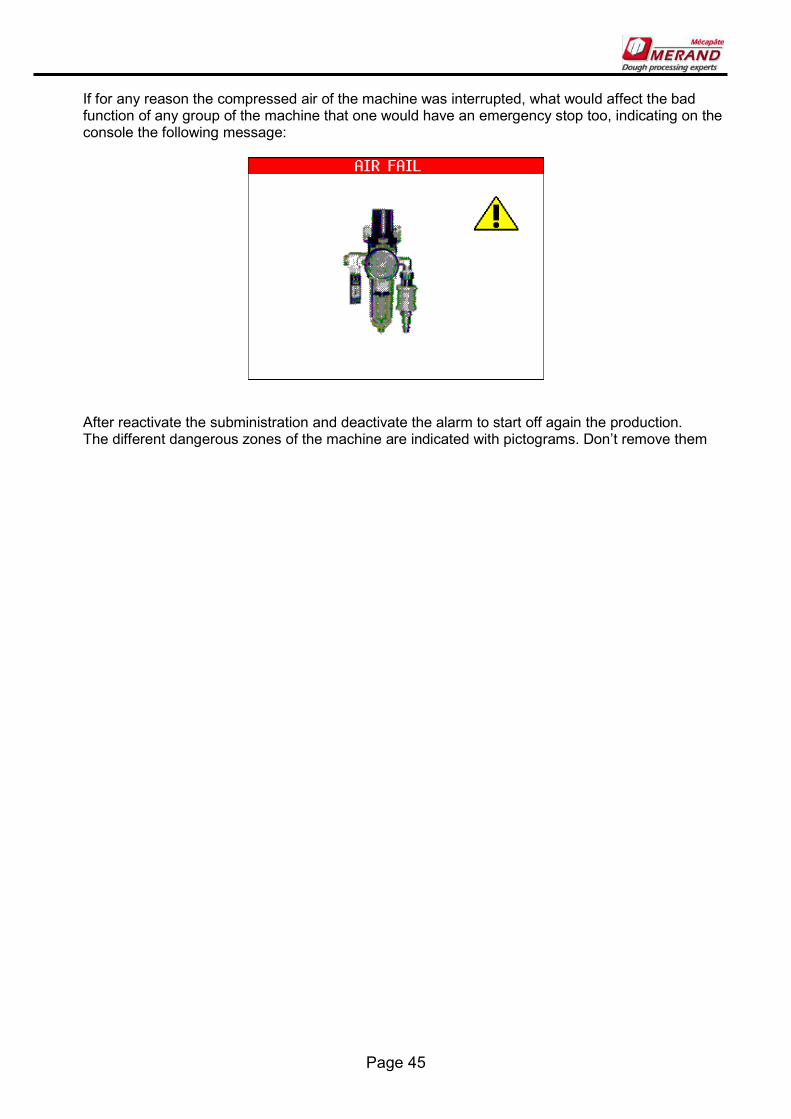
If for any reason the compressed air of the machine was interrupted, what would affect the bad function of any group of the machine that one would have an emergency stop too, indicating on the console the following message:
After reactivate the subministration and deactivate the alarm to start off again the production. The different dangerous zones of the machine are indicated with pictograms. Don’t remove them

Page 46
21. RELATIVE RECOMMENDATIONS OF SECURITY AND OBLIGATION COMPIANCE 1- The Ciabatta SERIE 250 has been built for the formation of different products of bread hydrates mass or other masses of bakery. Other use is prohibited. The accidents caused by the utilization of the machine not expected by the constructor will not be responsible for the action, being the risk for the user. 2- The machine is done for being used by adults and qualified personal. Its use is prohibited for under age people. 3- The use, the maintenance and reparation of the machine will be done how its said in this manual. Every intervention not written in the manual will have to be authorized by Merand 4- the work done on the electrical part of the machine will be done by qualified personal and respecting the security specified regulation. 5- The withdrawal will be done by qualified personal and always that the machine is out of order. 6- The security disposals can’t be modified or cancelled nor mechanical or electric ways. 7- Don’t put your hands under the protections. 8-the maintenance work will be done with de machine disconnected. 9- Any out of order piece will only be substitute for a original spare parts. 10-It’s totally prohibited to do any modification mechanical, electrical or in the software without the consent of the manufacture. Merand declines all responsibility of any situation provoked for the non compliment of any of the previous recommendations.

Mérand Mécapâte Z.I. de la Turbanière. Brécé - BP 93329 35 533 Noyal-sur-Vilaine. FRANCE Web: www.merand.fr
Page 48
22. INSTRUCTIONS POUR LE MISE A SERVICE ET MANTENANCE DU:
CIABATTERA AQUAPAN 100
NOTE IMPORTANTE : LIRE CE MANUEL AVANT DE METTRE LA MACHINE À SERVICE. CONSERVER POUR DES USAGES FUTURS.
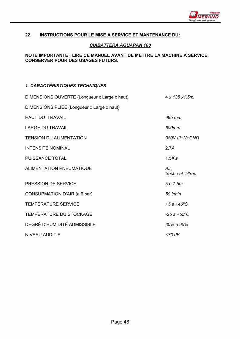
1. CARACTÉRISTIQUES TECHNIQUES
DIMENSIONS OUVERTE (Longueur x Large x haut) 4 x 135 x1,5m. DIMENSIONS PLIÉE (Longueur x Large x haut) HAUT DU TRAVAIL 985 mm LARGE DU TRAVAIL 600mm TENSION DU ALIMENTATIÓN 380V III+N+GND INTENSITÉ NOMINAL 2,7A PUISSANCE TOTAL 1.5Kw ALIMENTATION PNEUMATIQUE Air, Sèche et filtrée PRESSION DE SERVICE 5 a 7 bar CONSUPMATION D’AIR (a 6 bar) 50 l/min TEMPÉRATURE SERVICE +5 a +40ºC TEMPÉRATURE DU STOCKAGE -25 a +55ºC DEGRÉ D'HUMIDITÉ ADMISSIBLE 30% a 95% NIVEAU AUDITIF <70 dB

Page 49
23. DESCRIPTION La machine est dessinée et construite pour à la fabrication du pain ciabatta et d'autres types du pain artisan et hydraté. La machine permet d'obtenir un drap de masse avec grosseur et une largeur uniforme à partir des portions originaires d'une masseuse, une trémie des portions ou un autre système d'alimentation automatique de masse. Ce drap est coupé d'abord longitudinalement et après on réalise une coupure transversale, oblique ou autre en dépendant du coin. La machine est programmable électroniquement pour déterminer les caractéristiques du produit à se ranger tels comme vitesses des rubans, longueur du produit. La machine est composée des groupes suivants:(figure 1)
7. Convoyeur d’entrée 8. Guides Latérales 9. Lamination Multirrouleaux
10. Gare du coupeur. 11. Guillotine pneumatique. 12. Convoyeur de sortie
figure1 La machine est dessinée pour l'incorporation possible postérieure d'autres accessoires pour la formation d'autres produits. Se mettre en rapport avec Mérand-Mecapâte pour cette possibilité
1 2 3 4 5 6

Page 50
24. INSTALLATION DE STOCKAGE ET DE LA MACHINE
24.1. INSTALLATION ET MISE EN SERVICE L'installation et une mise dans un service de la machine sera effectuée par le service technique de Mérand Mecapâte ou par un personnel autorisé. La machine dispose des roues tournantes avec frein pour faciliter la copie de la même. La connexion électrique générale de la machine sera faite dans le relier disposé depuis telle fin dans le boîte électrique marqué GND N avec un tuyau d'arrosage de 3 x 2.5mm. Pour plus de détails voir un schéma électrique
24.2. STOCKAGE DE LA MACHINE Au cas où avoir à rester la machine hors d'usage durant le temps prolongé(oblong) est importante observer les recommandations suivantes :
- Nettoyer parfaitement la machine de restes de masse ou de farine.
- Garder dans un endroit sans humidité et des températures extrêmes.
- Couvrir la machine d'un tissu ó un plastique pour la protéger de la poussière et la saleté.
- Déconnecter l'alimentation électrique et pneumatique.
- Ne pas laisser de matrice placée dans la guillotine.
- Protéger les matrices avec une légère cape d'huile SAE 40.

Page 51
25. RÉGULATION ET AJUSTEMENTS MÉCANIQUES La machine vient ajustée de fabrique ou dans sa mise en service par le personnel technique. Cependant existent quelques ajustements qui peuvent être effectués par la suite s'ils varieront les conditions d'usage. Ensuite les dits ajustements le groupe sont détaillés à un groupe..
25.1. CONVOYEUR D’ENTRÉE
TENSION DE LES CONVOYEURS
Le convoyeur d'alimentation peut être tendue ó relâchée si les toiles à voile patinaient sur les rouleaux ó elles resteront freinées. Pour cela nous agirons sur les vis tenseur À (Figure 1) prêts aux deux côtés de la machine. Nous relâcherons l'écrou B et au moyen de la vis nous tendrons ó relâcherons la toile à voile toujours uniformément aux deux côtés. Recommencer à serrer toujours l'écrou B quand l'opération a été achevée de tendu. .
Figure 1 Important : Ce n'est pas convenable laisser la bande excessivement tendue.
CENTRE DE LE CONVOYEUR Si la bande avait la tendance de se déplacer latéralement sur les rouleaux, on procédera à son centré de la forme suivante : Tendre lentement la bande une transporteuse seulement du côté où il(elle) se déplace jusqu'à ce que l'on observe qu'il(elle) commence à se déplacer vers le côté contrarié. Dans ce moment détenser légèrement du même côté, jusqu'à ce que nous observions qu'elle se maintient centrée. Répéter le processus si c'était nécessaire. Le processus de centré des toiles à voile est lent et requiert avoir une patience.
A
B

Page 52
25.2. COUPEUR LONGEUR
CHANGE AXE COUPEUR Pour le change d'un produit il est nécessaire de changer l'axe de couperets de coupure longitudinale. Le procédé est le suivant : - Libérer le crochet qui fixe la guillotine et la monter(lever) vers le haut pour pouvoir accéder avec commodité à l'axe de coupure. - Lever les leviers A (Figure 2) jusqu'à ce que les extrémités de l'axe de couperets sortent de la fixation latérale. - Nous avons maintenant les rouleaux libres pour pouvoir les retirer, et substituer par un autre axe pour un nouveau produit. - Le processus de montage est le même à l'inverse.
Figure 2
AJUSTEMENT MESURE COUPERETS
Libérer les couperets de l'axe en relâchant les vis les prisonniers A (Figure 3). Mouvoir les couperets à sa nouvelle position, recommencer à serrer les vis des prisonniers. IMPORTANT : Effectuer cette opération avec l'axe les couperets outre la station de coupure.
Figure 3
A
A

Page 53
25.3. GUILLOTINE PNEUMATIQUE
CHANGER LA MATRICE
Le procédé pour le changement de la matrice est le suivant: Ouvrir la porte de la guillotine, lâcher les assurances des pivots de fixation À (Figure 4) et les tirer de la fourche pour libérer la matrice de ses ancrages. Tirer de la matrice vers le bas, avec ce que cela nous restera libre. La retirer et la substituer par la nouvelle matrice, pour cela, introduire la matrice dans les ancrages, placer les pivots et fermer les assurances pour que la matrice reste. Remarque: Avant de mettre en place la guillotine il est convenable de vérifier que la nouvelle matrice est correctement réglée. (Voir le partie suivante).
Figure 4
AJUSTEMENT DE LA MATRICE Pour une coupure correcte de la matrice, cela existe à avoir correctement été règle par rapport à la surface de la convoyeur. Au moyen d'eux baisse B (Figure 4) de l'axe du cylindre, nous pouvons régler la hauteur de chacun des extrémités de la matrice jusqu'à ce qu'une transporteuse soit complètement à un niveau avec la bande et qu'il y ait une grosse réalité, la bande et la guillotine équivalente à une feuille fine de papier. Si la coupure n'était pas uniforme dans toute la largeur, nous procéderons à baisser du côté où j'ai moins coupé, jusqu'à obtenir une coupure égale. Remarque: Selon le type de masse à couper il est possible que la guillotine doit être plus basse du conseillé dans la partie antérieure, veiller chaque fois n'arrive pas à marquer la convoyeur.
A
B
Page 54
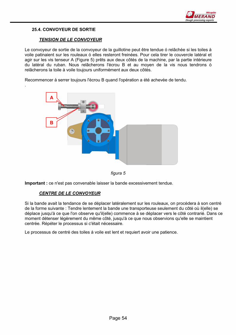
25.4. CONVOYEUR DE SORTIE
TENSION DE LE CONVOYEUR Le convoyeur de sortie de la convoyeur de la guillotine peut être tendue ó relâchée si les toiles à voile patinaient sur les rouleaux ó elles resteront freinées. Pour cela tirer le couvercle latéral et agir sur les vis tenseur A (Figure 5) prêts aux deux côtés de la machine, par la partie intérieure du latéral du ruban. Nous relâcherons l'écrou B et au moyen de la vis nous tendrons ó relâcherons la toile à voile toujours uniformément aux deux côtés. Recommencer à serrer toujours l'écrou B quand l'opération a été achevée de tendu. .
figura 5 Important : ce n'est pas convenable laisser la bande excessivement tendue.
CENTRE DE LE CONVOYEUR Si la bande avait la tendance de se déplacer latéralement sur les rouleaux, on procédera à son centré de la forme suivante : Tendre lentement la bande une transporteuse seulement du côté où il(elle) se déplace jusqu'à ce que l'on observe qu'il(elle) commence à se déplacer vers le côté contrarié. Dans ce moment détenser légèrement du même côté, jusqu'à ce que nous observions qu'elle se maintient centrée. Répéter le processus si c'était nécessaire.
Le processus de centré des toiles à voile est lent et requiert avoir une patience.
A
B
Page 55
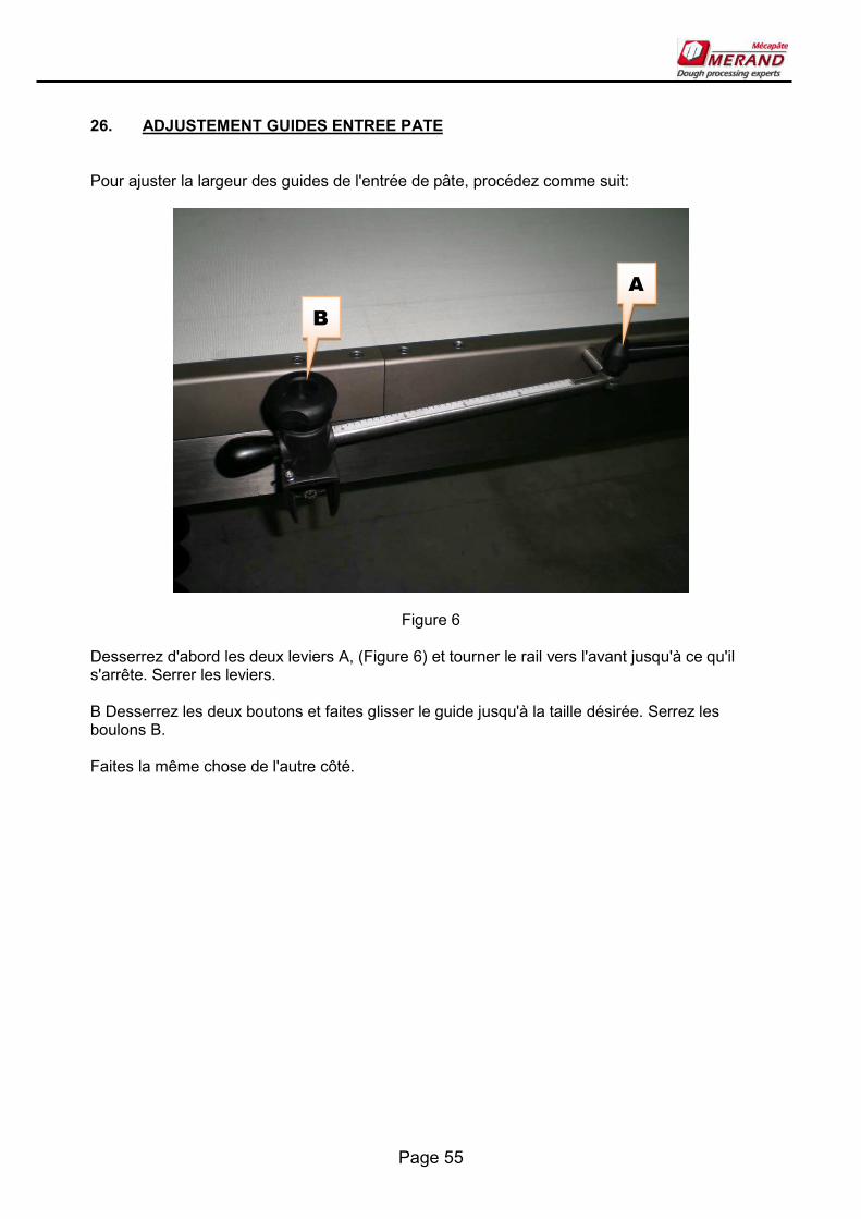
26. ADJUSTEMENT GUIDES ENTREE PATE Pour ajuster la largeur des guides de l'entrée de pâte, procédez comme suit:
Figure 6 Desserrez d'abord les deux leviers A, (Figure 6) et tourner le rail vers l'avant jusqu'à ce qu'il s'arrête. Serrer les leviers. B Desserrez les deux boutons et faites glisser le guide jusqu'à la taille désirée. Serrez les boulons B. Faites la même chose de l'autre côté.
Page 56
UTILISATION DE LA MACHINE
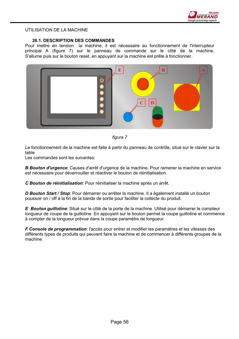
26.1. DESCRIPTION DES COMMANDES Pour mettre en tension la machine, il est nécessaire au fonctionnement de l'interrupteur principal A (figure 7) sur le panneau de commande sur le côté de la machine. S'allume puis sur le bouton reset, en appuyant sur la machine est prête à fonctionner.
figura 7 Le fonctionnement de la machine est faite à partir du panneau de contrôle, situé sur le clavier sur la table Les commandes sont les suivantes: B Bouton d'urgence: Causes d'arrêt d'urgence de la machine. Pour ramener la machine en service est nécessaire pour déverrouiller et réactiver le bouton de réinitialisation. C Bouton de réinitialisation: Pour réinitialiser la machine après un arrêt. D Bouton Start / Stop: Pour démarrer ou arrêter la machine. Il a également installé un bouton poussoir on / off à la fin de la bande de sortie pour faciliter la collecte du produit. E Bouton guillotine: Situé sur le côté de la porte de la machine. Utilisé pour démarrer le compteur longueur de coupe de la guillotine. En appuyant sur le bouton permet la coupe guillotine et commence à compter de la longueur prévue dans la coupe paramètre de longueur. F Console de programmation: l'accès pour entrer et modifier les paramètres et les vitesses des différents types de produits qui peuvent faire la machine et de commencer à différents groupes de la machine.
A
C D
B E

Page 57
26.2. CONSOLE DE PROGRAMMATION. Lorsque la machine sous tension apparaît dans la console de programmation d'écran:
En la parte inferior de la misma encontramos unos iconos que nos dan acceso a las distintas funciones de la consola. VITESSE GLOBAL: Pour changer en une seule opération à toutes les vitesses de la machine. Expresse en % de la vitesse maximale. 100 est le maximum. MENU SELECTION PROGRAMME: Allez à la sélection du menu des programmes. MENU ON/OFF GROUPS: Accès au menu de sélection et de cesser les différents groupes de la machine. MENU SELECTION DE PARAMETRES: Allez dans le menu de sélection et la modification des différents paramètres de la machine. MENU SELECTION LANGUE ECRAN
A
C D E

Page 58
MENU SELECTION PROGRAMME En cliquant sur l'icône de sélection du programme vont à l'écran suivant:
On y trouve la liste des programmes et de définir le programme actif. En cliquant sur le nom d'un programme pour afficher un clavier alphanumérique qui nous permet de changer le nom du programme. En cliquant sur la case adjacente B, cela va changer la couleur en indiquant que c'est le programme sélectionné. Au fond, trouver l'icône de copie d'un programme C, ce menu nous permet de copier tous les paramètres d'un programme plutôt qu'un autre. Prendre que cette opération va écraser les valeurs précédentes du programme destination.
A
B
C

Page 59
MENU ON/OFF GROUPS Pour démarrer et arrêter les groupes machine en appuyant sur la touche STOP RUN MENU icône sur le menu principal de la machine. L'écran suivant apparaît. En cliquant sur chacun de ces groupes devient vert lorsque le groupe est en place et restent rouges quand ils sont éteints.

Page 60
MENU SELECTION DE PARAMETRES
En cliquant sur l'icône, sélectionnez Paramètres dans le menu principal pour accéder à l'écran suivant: Voici quelques caisses avec les noms des différentes parties de la machine. En cliquant sur eux, nous pouvons modifier ces paramètres de fonctionnement des différentes parties. Les paramètres peuvent être modifiés sont les suivants:
CONVEYEUR D’ENTRÉE: Indique la vitesse de la bande d'entrée du calibrateur. Indique la fréquence de fonctionnement du moteur en HZ CONVEYEUR SORTIE: Indique la vitesse de la bande de sortie de le calibrateur. Indique la fréquence de fonctionnement du moteur en HZ LONGUEUR COUPER: Indique la distance en millimètres pour faire progresser le convoyeur entre chaque tranche de la guillotine. HAUTEUR ROULEAUX: Indique la valeur à définir l'affichage numérique de multi-rouleaux i exprime la hauteur de la machine à laminer. Cette mesure n'a aucun effet sur les mécanismes de la machine, il convient d'adapter manuellement. SEPARATION PELLES: Indique ce qui marquent les règles des guides d’entrée. Cette mesure n'a aucun effet sur les mécanismes de la machine, il convient d'adapter manuellement.

Page 61
27. NETTOYAGE ET ENTRETIEN
27.1. NETTOYAGE DE LA MACHINE Après chaque utilisation ou à la fin de la journée doit inclure le nettoyage qui suit: 1. Retirez de la machine et nettoyez tous les accessoires utilisés: coupe l'axe, coupant la matrice, etc. ... Ces accessoires peuvent être lavés avec du savon et de l'eau non-toxique et doit être séché à fond après le nettoyage. 2. Aspirer ou souffler toute trace de farine et de sucre ont été dans la machine. 3. Retirez toute la masse restante a été constaté ci-dessus la table ou dans un coin. 4. Nettoyer les convoyeurs, d'abord avec une brosse pour enlever le sucre et la farine, puis avec un chiffon humide et un savon doux non-toxiques. Avancé pour nettoyer la toile sur toute sa longueur 5. Pour nettoyer les tables et autres éléments de la structure en acier est recommandé tous les produits spécifiques pour le nettoyage en acier inoxydable. Périodiquement vide ou coup la farine et la poussière qui peut avoir pénétré le tableau électrique.
27.2. TABLES PLIANTES La table pliante qui sert à stocker la machine lorsqu'elle n'est pas utilisée, occupent moins d'espace Table d'entrée: Commencez par retirer arriéré les guides de pâte. Pour ce faire, desserrez les deux boutons B (fig. 8) et faites glisser les guides à leur séparation minimum. Serrez les boutons. Desserrez ensuite et tournez les poignées pour les guides à son arrière. Resserrer les poignées. Tirez le verrouillage de sécurité C et de déplacer la table jusqu'à ce qu'il dépasse la position verticale (Vous pourriez avoir à le faire entre deux personnes). La goupille de sécurité doit s'intégrer dans leur nouvelle position. Pour le tableau de sortir de la même façon, pas de guides à la retraite.

Page 62
27.3.
Figure 8
27.4. STOCKAGE DES ACCESSOIRES Pour enregistrer la coupe des pièces jointes qui ne sont pas utilisé la machine a un support sur le fond à cet effet. Vous pouvez ouvrir pour un accès pratique à partir du côté de contrôle de la machine. Les rouleaux de coupe sont situés dans la dentelle sur le devant, les matrices sont suspendus à l'arrière.
C

Page 63
27.5. ENTRETIEN La machine est conçue pour le niveau de l'entretien normal est faible, les éléments plupart sont graissés à vie ou tendeurs de chaîne automatique. Cependant, il ya quelques opérations avec un bon nettoyage de la machine contribue à une plus longue vie de celle-ci. Dans le calibrateur: Graisser la chaîne d'entraînement sur une base mensuelle, utilisez de la graisse de lithium Graisser vis régulation hauteur mensuelle. Vérifier la tension et le centrage du convoyeur hebdomadaire. Dans les tables a travail Revue hebdomadaire et l'équilibre de la tension de la toile. Hebdomadaire de purge du réservoir ou le filtre à air plus souvent si plus de la moitié de l'eau. Pour enlever le bouchon de purge (Figure 16) A.
figura 16 Toutes les opérations détaillés ici, doivent être faites à des intervalles plus courts que celui indiqué si les conditions de service de l'équipement dont ils ont besoin.
A

Page 64
28. CARACTERISTIQUES DE SECURITE La machine a des plafonds amovibles qui protègent les pièces en mouvement, les transmissions, courroies, des moteurs, tableau électrique, et d'autres éléments qui peuvent présenter un risque et dont la manipulation n'est pas nécessaire pour une utilisation de routine de la machine. Ces plafonds sont fixés par des vis Allen un outil est nécessaire afin qu'ils puissent être correctement supprimés. Cette opération se fait uniquement par du personnel qualifié pour l'entretien et la réparation, et toujours avec la machine hors tension et débranché. Vous êtes également interdit de mettre la machine en marche sans les plafonds et fixé par des vis. Il a également une protecteurs pivotants à l'entrée et la sortie des coupeurs et rouleaux pour une utilisation facile de la machine d'alimentation et de nettoyage. Ces gardes sont des micro-interrupteurs électriques qui empêchent la mise en œuvre de la machine si elles sont ouvertes, et provoquer l'arrêt si la machine est ouvert. Dans ces cas apparaissent dans l'affichage de la console de programmation des messages suivants:
IMPORTANT: Pour configurer la machine en marche après un arrêt d'urgence est nécessaire de fermer les micro-interrupteurs ouverts et appuyez sur le bouton de réinitialisation pour désactiver l'alarme IMPORTANT: Suivez qu'il n'y a pas d'objet: des outils, des chiffons, brosses, etc .... Ci-dessus les bandes avant de les appliquer. La machine a plusieurs arrêts d'urgence situés de chaque côté de lui causer un arrêt total de la machine, il soit nécessaire de déverrouiller et de la mise sous tension pour revenir au service. Si pour une raison quelconque a interrompu la fourniture d'air comprimé à la machine, ce qui provoque un dysfonctionnement de la machine qui groupe aussi l'objet d'un arrêt d'urgence de donner la console le message suivant:

Page 65
Devrait reprendre l'approvisionnement de celui-ci et de désactiver l'alarme pour relancer la production. Les différentes zones de danger de la machine sont bien identifiés par des pictogrammes. Ne pas déplacer ou supprimer de tels signaux.

Page 66
29. RECOMMANDATIONS CONCERNANT LA SECURITE DE LA CONFORMITE EXIGEE
1 - AQUAPAN a été construit pour la formation de divers produits de pâte à pain et d'autres pâtes hydratés de boulangerie. Toute autre utilisation est interdite. Les accidents résultant d'une utilisation non prévue par le constructeur ne sont pas imputables à elle, être à vos propres risques. 2 - La machine est destiné à être utilisé par des adultes et enseignés par un personnel qualifié. Il est interdit d'utiliser ou de la manipulation par des enfants. 3 - L'utilisation, d'entretien et de réparation seront effectués comme indiqué dans ce manuel. Toute intervention ne figure pas dans le même doit être approuvé par Mérand 4-Les travaux sur la partie électrique de la machine doivent être réalisés par du personnel qualifié et en conformité avec les normes de sécurité établies 5- Le retrait des enveloppes fixées ne se faira que par un personnel formé et fourni avec la machine hors service, devant être placé avant de commencer. 6-dispositifs de sécurité ne devrait pas être modifiée ou annulée ou mécanique ou électrique. 7 - Ne pas mettre les mains sous la protection 8-Les travaux d'entretien seront effectués avec la machine découpe électrique et pneumatique. 9-Toute pièce endommagée est remplacée par une partie d'origine. 10-Il est interdit d'apporter des modifications aux systèmes mécaniques, électriques ou d'un logiciel sans le consentement du fabricant. Mérand décline toute responsabilité en cas de situation résultant de la non-conformité avec l'une des recommandations ci-dessus.

Page 67

Mérand Mécapâte Z.I. de la Turbanière. Brécé - BP 93329 35 533 Noyal-sur-Vilaine. FRANCE Web: www.merand.fr

Page 69
30. ESQUEMAS ELECTRICOS/ ELECTRIC PLANS/ SCHEMAS ELECTRIQUES
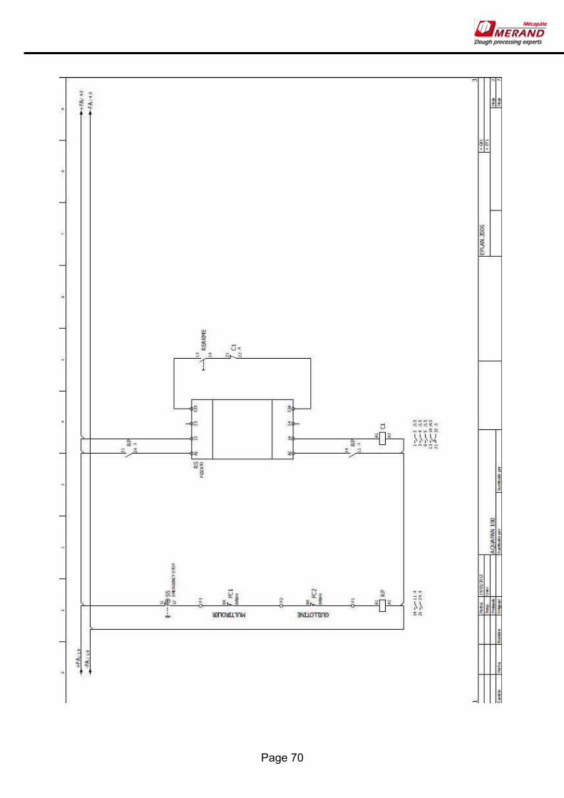
Page 70

Page 71

Page 72

Page 73

Page 74

Page 75

Mérand Mécapâte Z.I. de la Turbanière. Brécé - BP 93329 35 533 Noyal-sur-Vilaine. FRANCE Web: www.merand.fr
31. DESPIECE MAQUINA/ SPARE LIST/ LISTE DES PIÈCES

Page 77

Page 78

Page 79

Page 80

Page 81
Page 82
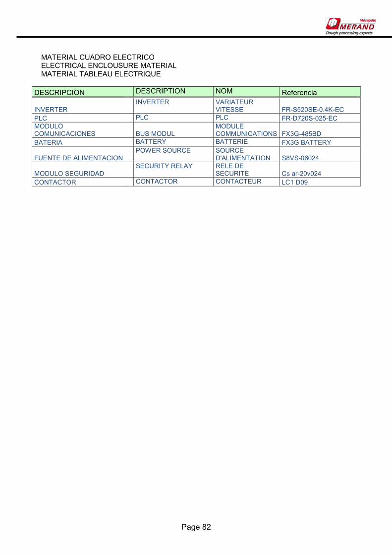
MATERIAL CUADRO ELECTRICO ELECTRICAL ENCLOUSURE MATERIAL MATERIAL TABLEAU ELECTRIQUE
DESCRIPCION DESCRIPTION NOM Referencia
INVERTER INVERTER VARIATEUR
VITESSE FR-S520SE-0.4K-EC PLC PLC PLC FR-D720S-025-EC MODULO COMUNICACIONES
BUS MODUL
MODULE COMMUNICATIONS FX3G-485BD
BATERIA BATTERY BATTERIE FX3G BATTERY
FUENTE DE ALIMENTACION POWER SOURCE SOURCE
D'ALIMENTATION S8VS-06024
MODULO SEGURIDAD SECURITY RELAY RELE DE
SECURITE Cs ar-20v024 CONTACTOR CONTACTOR CONTACTEUR LC1 D09

Page 83
32.

VERSION 100.3 FECHA DE EDICION 19/1/2012