manual 770 extreme3
TRANSCRIPT
11111
770 Extreme3
User Manual
Version 1.0Published February 2010
Copyright©2010 ASRock INC. All rights reserved.
22222
Copyright Notice:Copyright Notice:Copyright Notice:Copyright Notice:Copyright Notice:No part of this manual may be reproduced, transcribed, transmitted, or translated inany language, in any form or by any means, except duplication of documentation bythe purchaser for backup purpose, without written consent of ASRock Inc.Products and corporate names appearing in this manual may or may not be regis-tered trademarks or copyrights of their respective companies, and are used only foridentification or explanation and to the owners’ benefit, without intent to infringe.
Disclaimer:Disclaimer:Disclaimer:Disclaimer:Disclaimer:Specifications and information contained in this manual are furnished for informa-tional use only and subject to change without notice, and should not be constructedas a commitment by ASRock. ASRock assumes no responsibility for any errors oromissions that may appear in this manual.With respect to the contents of this manual, ASRock does not provide warranty ofany kind, either expressed or implied, including but not limited to the implied warran-ties or conditions of merchantability or fitness for a particular purpose.In no event shall ASRock, its directors, officers, employees, or agents be liable forany indirect, special, incidental, or consequential damages (including damages forloss of profits, loss of business, loss of data, interruption of business and the like),even if ASRock has been advised of the possibility of such damages arising from anydefect or error in the manual or product.
This device complies with Part 15 of the FCC Rules. Operation is subject to thefollowing two conditions:(1) this device may not cause harmful interference, and(2) this device must accept any interference received, including interference that
may cause undesired operation.
CALIFORNIA, USA ONLYThe Lithium battery adopted on this motherboard contains Perchlorate, a toxicsubstance controlled in Perchlorate Best Management Practices (BMP) regulationspassed by the California Legislature. When you discard the Lithium battery inCalifornia, USA, please follow the related regulations in advance.“Perchlorate Material-special handling may apply, seewww.dtsc.ca.gov/hazardouswaste/perchlorate”
ASRock Website: http://www.asrock.com
33333
ContentsContentsContentsContentsContents1 .1 .1 .1 .1 . IntroductionIntroductionIntroductionIntroductionIntroduction ....................................................................................................................................................................................................................................................................................................... 5 5 5 5 5
1.1 Package Contents ..................................................................... 51.2 Specifications ............................................................................ 61.3 Motherboard Layout ................................................................... 101.4 I/O Panel .................................................................................... 11
2.2.2.2.2. InstallationInstallationInstallationInstallationInstallation ...................................................................................................................................................................................................................................................................................................................... 12 12 12 12 12Pre-installation Precautions ............................................................... 122.1 CPU Installation ......................................................................... 132.2 Installation of CPU Fan and Heatsink ....................................... 132.3 Installation of Memory Modules (DIMM) .................................... 142.4 Expansion Slots (PCI and PCI Express Slots) .......................... 162.5 Jumpers Setup .......................................................................... 172.6 Onboard Headers and Connectors .......................................... 182.7 HDMI_SPDIF Header Connection Guide .................................... 242.8 Serial ATA (SATA) / Serial ATAII (SATAII) Hard Disks
Installation ................................................................................. 252.9 Serial ATA3 (SATA3) Hard Disks Installation ............................ 252.10 Hot Plug and Hot Swap Functions for SATA / SATAII HDDs .... 262.11 Hot Plug and Hot Swap Functions for SATA3 HDDs ............... 262.12 SATA / SATAII HDD Hot Plug Feature and Operation Guide ..... 272.13 Driver Installation Guide ............................................................ 292.14 Installing Windows® 7 / 7 64-bit / VistaTM / VistaTM 64-bit / XP /
XP 64-bit With RAID Functions ................................................. 292.14.1 Installing Windows® XP / XP 64-bit With RAID
Functions .................................................................... 292.14.2 Installing Windows® 7 / 7 64-bit / VistaTM / VistaTM 64-bit
With RAID Functions ..................................................... 302.15 Installing Windows® 7 / 7 64-bit / VistaTM / VistaTM 64-bit / XP /
XP 64-bit Without RAID Functions ............................................ 312.15.1 Installing Windows® XP / XP 64-bit Without RAID
Functions ...................................................................... 312.15.2 Installing Windows® 7 / 7 64-bit / VistaTM / VistaTM 64-bit
Without RAID Functions ................................................ 322.16 Untied Overclocking Technology .............................................. 33
3.3.3.3.3. BIOS SBIOS SBIOS SBIOS SBIOS SETUP UTILITYETUP UTILITYETUP UTILITYETUP UTILITYETUP UTILITY ............................................................................................................................................................................................................................................................... 34 34 34 34 343.1 Introduction ............................................................................... 34
3.1.1 BIOS Menu Bar ............................................................... 343.1.2 Navigation Keys ............................................................. 35
44444
3.2 Main Screen .............................................................................. 353.3 OC Tweaker Screen ................................................................. 363.4 Advanced Screen .................................................................... 43
3.4.1 CPU Configuration .......................................................... 443.4.2 Chipset Configuration ..................................................... 453.4.3 ACPI Configuration ......................................................... 463.4.4 Storage Configuration .................................................... 473.4.5 PCIPnP Configuration ...................................................... 493.4.6 Floppy Configuration ...................................................... 503.4.7 Super IO Configuration ................................................... 503.4.8 USB Configuration .......................................................... 51
3.5 Hardware Health Event Monitoring Screen ............................. 523.6 Boot Screen .............................................................................. 53
3.6.1 Boot Settings Configuration ........................................... 533.7 Security Screen ........................................................................ 543.8 Exit Screen ............................................................................... 55
4.4.4.4.4. Software SupportSoftware SupportSoftware SupportSoftware SupportSoftware Support ............................................................................................................................................................................................................................................................... 56 56 56 56 564.1 Install Operating System ........................................................... 564.2 Support CD Information ............................................................. 56
4.2.1 Running Support CD ....................................................... 564.2.2 Drivers Menu .................................................................. 564.2.3 Utilities Menu ................................................................... 564.2.4 Contact Information ........................................................ 56
55555
1.1.1.1.1. IntroductionIntroductionIntroductionIntroductionIntroductionThank you for purchasing ASRock 770 Extreme3 motherboard, a reliable motherboardproduced under ASRock’s consistently stringent quality control. It delivers excellentperformance with robust design conforming to ASRock’s commitment to quality andendurance.In this manual, chapter 1 and 2 contain introduction of the motherboard and step-by-stepguide to the hardware installation. Chapter 3 and 4 contain the configuration guide toBIOS setup and information of the Support CD.
Because the motherboard specifications and the BIOS software might beupdated, the content of this manual will be subject to change withoutnotice. In case any modifications of this manual occur, the updatedversion will be available on ASRock website without further notice. Youmay find the latest VGA cards and CPU support lists on ASRock websiteas well. ASRock website http://www.asrock.comIf you require technical support related to this motherboard, please visitour website for specific information about the model you are using.www.asrock.com/support/index.asp
1.11 .11 .11 .11 .1 PPPPPackackackackackage Contentsage Contentsage Contentsage Contentsage ContentsASRock 770 Extreme3 Motherboard
(ATX Form Factor: 12.0-in x 8.2-in, 30.5 cm x 20.8 cm)ASRock 770 Extreme3 Quick Installation GuideASRock 770 Extreme3 Support CD1 x Ultra ATA 66/100/133 IDE Ribbon Cable (80-conductor)2 x Serial ATA (SATA) Data Cables (Optional)1 x Serial ATA (SATA) HDD Power Cable (Optional)1 x I/O Panel Shield
66666
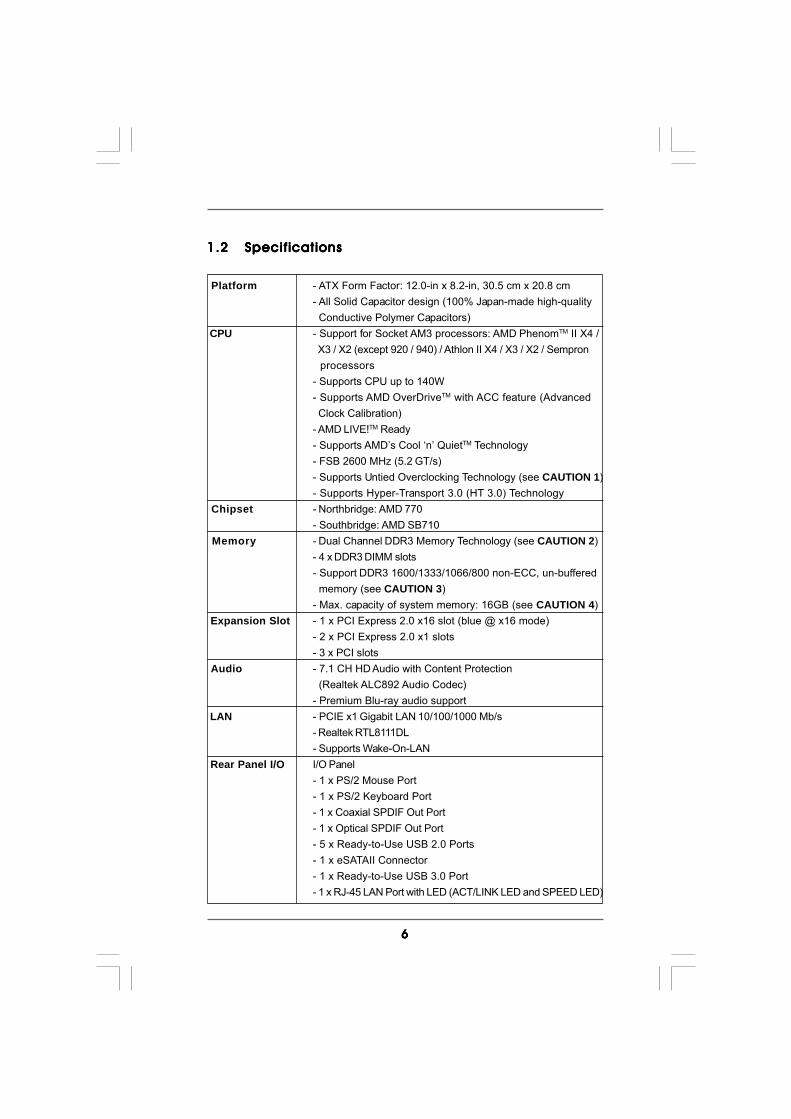
1.21.21.21.21.2 SpecificationsSpecificationsSpecificationsSpecificationsSpecifications
Platform - ATX Form Factor: 12.0-in x 8.2-in, 30.5 cm x 20.8 cm- All Solid Capacitor design (100% Japan-made high-quality Conductive Polymer Capacitors)
CPU - Support for Socket AM3 processors: AMD PhenomTM II X4 / X3 / X2 (except 920 / 940) / Athlon II X4 / X3 / X2 / Sempron processors- Supports CPU up to 140W- Supports AMD OverDriveTM with ACC feature (Advanced Clock Calibration)- AMD LIVE!TM Ready- Supports AMD’s Cool ‘n’ QuietTM Technology- FSB 2600 MHz (5.2 GT/s)- Supports Untied Overclocking Technology (see CAUTION 1)- Supports Hyper-Transport 3.0 (HT 3.0) Technology
Chipset - Northbridge: AMD 770- Southbridge: AMD SB710
Memory - Dual Channel DDR3 Memory Technology (see CAUTION 2)- 4 x DDR3 DIMM slots- Support DDR3 1600/1333/1066/800 non-ECC, un-buffered memory (see CAUTION 3)- Max. capacity of system memory: 16GB (see CAUTION 4)
Expansion Slot - 1 x PCI Express 2.0 x16 slot (blue @ x16 mode)- 2 x PCI Express 2.0 x1 slots- 3 x PCI slots
Audio - 7.1 CH HD Audio with Content Protection (Realtek ALC892 Audio Codec)- Premium Blu-ray audio support
LAN - PCIE x1 Gigabit LAN 10/100/1000 Mb/s- Realtek RTL8111DL- Supports Wake-On-LAN
Rear Panel I/O I/O Panel- 1 x PS/2 Mouse Port- 1 x PS/2 Keyboard Port- 1 x Coaxial SPDIF Out Port- 1 x Optical SPDIF Out Port- 5 x Ready-to-Use USB 2.0 Ports- 1 x eSATAII Connector- 1 x Ready-to-Use USB 3.0 Port- 1 x RJ-45 LAN Port with LED (ACT/LINK LED and SPEED LED)
77777
- HD Audio Jack: Side Speaker/Rear Speaker/Central/Bass/
Line in/Front Speaker/Microphone (see CAUTION 5)
SATA3 - 2 x SATA3 6.0Gb/s connectors by Marvell SE9123/9120,
support NCQ, AHCI and “Hot Plug” functions
USB 3.0 - 1 x USB 3.0 port by Fresco FL1000G, support USB 3.0 up to
5Gb/s
Connector - 4 x SATAII 3.0Gb/s connectors, support RAID (RAID 0,
RAID 1, RAID 10 and JBOD), NCQ, AHCI and “Hot Plug”
functions
- 2 x SATA3 6.0Gb/s connectors
- 1 x ATA133 IDE connector (supports 2 x IDE devices)
- 1 x Floppy connector
- 1 x IR header
- 1 x COM port header
- 1 x HDMI_SPDIF header
- 1 x Power LED header
- CPU/Chassis/Power FAN connector
- 24 pin ATX power connector
- 8 pin 12V power connector
- CD in header
- Front panel audio connector
- 3 x USB 2.0 headers (support 6 USB 2.0 ports)
(see CAUTION 6)
BIOS Feature - 8Mb AMI BIOS
- AMI Legal BIOS
- Supports “Plug and Play”
- ACPI 1.1 Compliance Wake Up Events
- Supports jumperfree
- SMBIOS 2.3.1 Support
- CPU VID Voltage Multi-adjustment
Support CD - Drivers, Utilities, AntiVirus Software (Trial Version), AMD
OverDriveTM Utility, ASRock Software Suite (CyberLink DVD
Suite and Creative Sound Blaster X-Fi MB) (OEM and Trial
Version)
Unique Feature - ASRock OC Tuner (see CAUTION 7)
- Intelligent Energy Saver (see CAUTION 8)
- Instant Boot
- ASRock Instant Flash (see CAUTION 9)
- ASRock OC DNA (see CAUTION 10)
- Hybrid Booster:
- CPU Frequency Stepless Control (see CAUTION 11)
- ASRock U-COP (see CAUTION 12)
88888
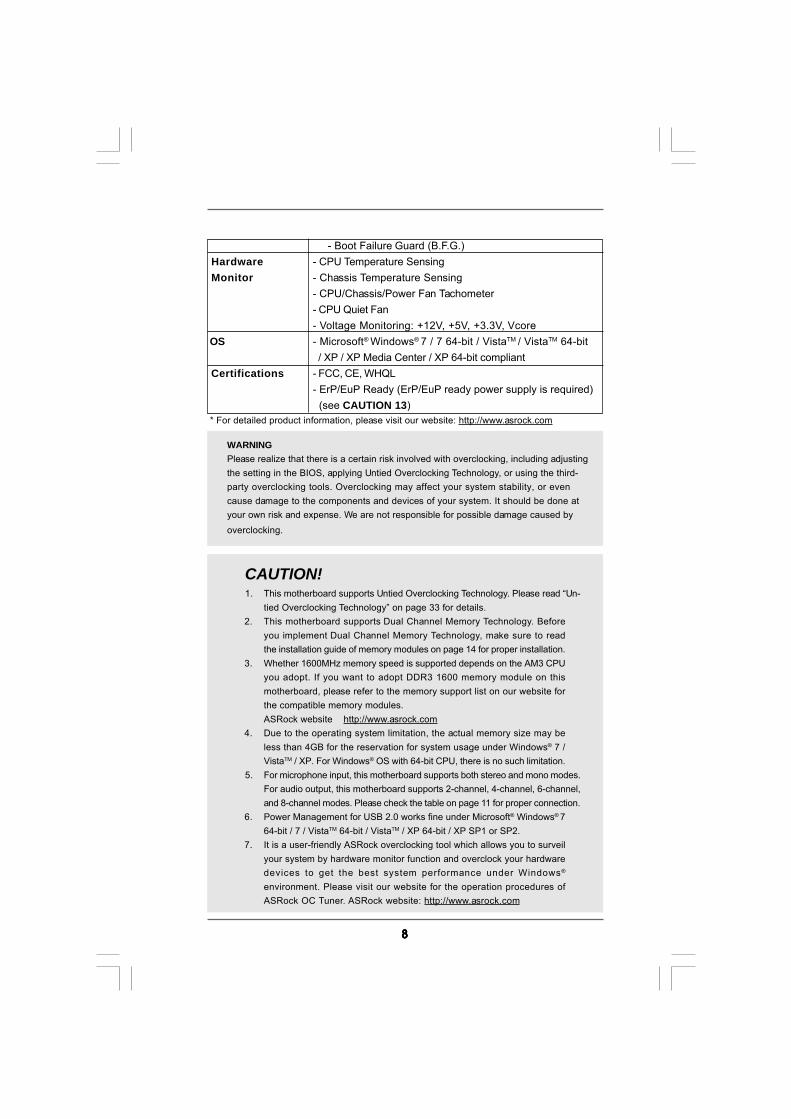
WARNINGPlease realize that there is a certain risk involved with overclocking, including adjustingthe setting in the BIOS, applying Untied Overclocking Technology, or using the third-party overclocking tools. Overclocking may affect your system stability, or evencause damage to the components and devices of your system. It should be done atyour own risk and expense. We are not responsible for possible damage caused byoverclocking.
CAUTION!1. This motherboard supports Untied Overclocking Technology. Please read “Un-
tied Overclocking Technology” on page 33 for details.2. This motherboard supports Dual Channel Memory Technology. Before
you implement Dual Channel Memory Technology, make sure to readthe installation guide of memory modules on page 14 for proper installation.
3. Whether 1600MHz memory speed is supported depends on the AM3 CPUyou adopt. If you want to adopt DDR3 1600 memory module on thismotherboard, please refer to the memory support list on our website forthe compatible memory modules.ASRock website http://www.asrock.com
4. Due to the operating system limitation, the actual memory size may beless than 4GB for the reservation for system usage under Windows® 7 /VistaTM / XP. For Windows® OS with 64-bit CPU, there is no such limitation.
5. For microphone input, this motherboard supports both stereo and mono modes.For audio output, this motherboard supports 2-channel, 4-channel, 6-channel,and 8-channel modes. Please check the table on page 11 for proper connection.
6. Power Management for USB 2.0 works fine under Microsoft® Windows® 764-bit / 7 / VistaTM 64-bit / VistaTM / XP 64-bit / XP SP1 or SP2.
7. It is a user-friendly ASRock overclocking tool which allows you to surveilyour system by hardware monitor function and overclock your hardwaredevices to get the best system performance under Windows®
environment. Please visit our website for the operation procedures ofASRock OC Tuner. ASRock website: http://www.asrock.com
- Boot Failure Guard (B.F.G.) Hardware - CPU Temperature Sensing Monitor - Chassis Temperature Sensing
- CPU/Chassis/Power Fan Tachometer- CPU Quiet Fan- Voltage Monitoring: +12V, +5V, +3.3V, Vcore
OS - Microsoft® Windows® 7 / 7 64-bit / VistaTM / VistaTM 64-bit / XP / XP Media Center / XP 64-bit compliant
Certifications - FCC, CE, WHQL- ErP/EuP Ready (ErP/EuP ready power supply is required) (see CAUTION 13)
* For detailed product information, please visit our website: http://www.asrock.com
99999
8. Featuring an advanced proprietary hardware and software design,Intelligent Energy Saver is a revolutionary technology that deliversunparalleled power savings. The voltage regulator can reduce thenumber of output phases to improve efficiency when the CPU cores areidle. In other words, it is able to provide exceptional power saving andimprove power efficiency without sacrificing computing performance.To use Intelligent Energy Saver function, please enable Cool ‘n’ Quietoption in the BIOS setup in advance. Please visit our website for theoperation procedures of Intelligent Energy Saver.ASRock website: http://www.asrock.com
9. ASRock Instant Flash is a BIOS flash utility embedded in Flash ROM.This convenient BIOS update tool allows you to update system BIOSwithout entering operating systems first like MS-DOS or Windows®. Withthis utility, you can press <F6> key during the POST or press <F2> key toBIOS setup menu to access ASRock Instant Flash. Just launch this tooland save the new BIOS file to your USB flash drive, floppy disk or harddrive, then you can update your BIOS only in a few clicks without prepar-ing an additional floppy diskette or other complicated flash utility. Pleasebe noted that the USB flash drive or hard drive must use FAT32/16/12 filesystem.
10. The software name itself – OC DNA literally tells you what it is capable of.OC DNA, an exclusive utility developed by ASRock, provides a conve-nient way for the user to record the OC settings and share with others. Ithelps you to save your overclocking record under the operating systemand simplifies the complicated recording process of overclocking settings.With OC DNA, you can save your OC settings as a profile and share withyour friends! Your friends then can load the OC profile to their own systemto get the same OC settings as yours! Please be noticed that the OCprofile can only be shared and worked on the same motherboard.
11. Although this motherboard offers stepless control, it is not recommendedto perform over-clocking. Frequencies other than the recommended CPUbus frequencies may cause the instability of the system or damage theCPU.
12. While CPU overheat is detected, the system will automatically shutdown.Before you resume the system, please check if the CPU fan on themotherboard functions properly and unplug the power cord, then plug itback again. To improve heat dissipation, remember to spray thermalgrease between the CPU and the heatsink when you install the PC system.
13. EuP, stands for Energy Using Product, was a provision regulated byEuropean Union to define the power consumption for the completed system.According to EuP, the total AC power of the completed system shall beunder 1.00W in off mode condition. To meet EuP standard, an EuP readymotherboard and an EuP ready power supply are required. According toIntel’s suggestion, the EuP ready power supply must meet the standard of5v standby power efficiency is higher than 50% under 100 mA currentconsumption. For EuP ready power supply selection, we recommend youchecking with the power supply manufacturer for more details.
1 01 01 01 01 0
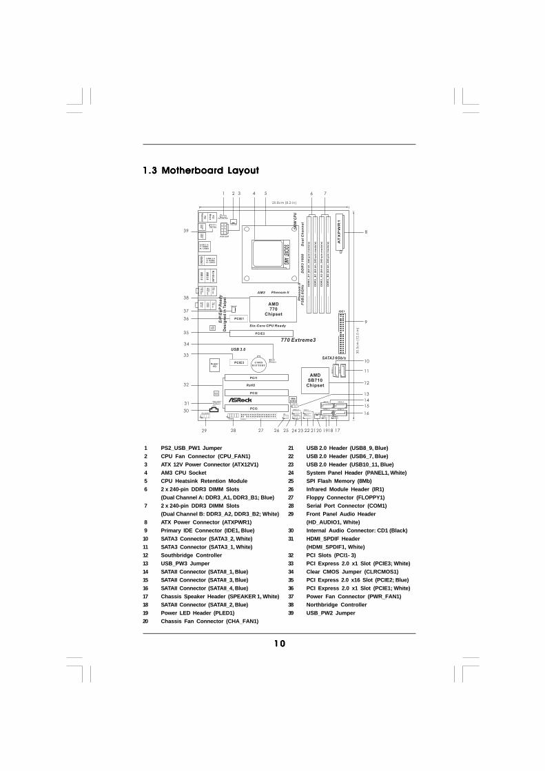
1.3 Motherboard Layout1.3 Motherboard Layout1.3 Motherboard Layout1.3 Motherboard Layout1.3 Motherboard Layout
IDE1
SOC
KETAM
3
FS
B8
00
DD
R3
_A
1(6
4b
it,2
40
-pin
mo
du
le)
DD
R3
_B
1(6
4b
it,2
40
-pin
mo
du
le)
FS
B8
00
DD
R3
_A
2(6
4b
it,2
40
-pin
mo
du
le)
DD
R3
_B
2(6
4b
it,2
40
-pin
mo
du
le)
AMDSB710
Chipset
PS2_USB_PW1
1
ATX12V1
CPU_FAN1
8MbBIOS
CMOSBATTERY
CLRCMOS1
1
COM1
LANPHY
1
AUDIOCODEC
SuperI/O
IR1
1
CD1
HD_AUDIO1
1
PCIE1
1
HDMI_SPDIF1
FLOPPY1 HDLED RESET
PLED PWRBTN
1
PANEL 1CHA_FAN1
SPEAKER1
1
USB8_9
1
USB6_7
1
SATAII_2
Ph
en
om
II
14
0W
CP
U
20.8cm (8.2-in)
30
.5c
m(1
2.0
-in
)
6 71 2 43 5
8
9
10
11
12
13
14
15
16
17181920212223242526272829
30
31
32
33
AMD770
Chipset
PCIE2
PCI1
PCI2
PCI3
770 Extreme3
SATAII_4
SATAII_1 SATAII_3
To
p:
SID
ES
PK
Ce
nte
r:R
EA
RS
PK
Bo
ttom
:C
TR
BA
SS
To
p:
LIN
EIN
Ce
nte
r:F
RO
NT
Bo
ttom
:M
ICIN
PS
2
Mo
us
e
PS
2K
eyboardC
oaxial
SP
DIF
Op
ticalS
PD
IF
USB 2.0T: USB4B: USB5
FS
B2
.6G
Hz
DD
R3
16
00
Du
al
Ch
an
ne
l
Six-Core CPU Ready
ErP
/Eu
PR
ea
dy
RoHS
Phenom II
USB10_11
1
PWR_FAN1
34
AM3
35
USB_PW2
1
PCIE3
1
PLED1
USB_PW3
1
SA
TA
3_
1
SA
TA
3_
2
USB 3.0
SATA3 6Gb/s
36
37
38
39
ES
ATA
1
USB 2.0T: USB2B: USB3
RJ-45
LA
N
US
B3.0
US
B2.0
De
sig
ne
din
Ta
ipe
i
1 PS2_USB_PW1 Jumper 21 USB 2.0 Header (USB8_9, Blue) 2 CPU Fan Connector (CPU_FAN1) 22 USB 2.0 Header (USB6_7, Blue) 3 ATX 12V Power Connector (ATX12V1) 23 USB 2.0 Header (USB10_11, Blue) 4 AM3 CPU Socket 24 System Panel Header (PANEL1, White) 5 CPU Heatsink Retention Module 25 SPI Flash Memory (8Mb) 6 2 x 240-pin DDR3 DIMM Slots 26 Infrared Module Header (IR1)
(Dual Channel A: DDR3_A1, DDR3_B1; Blue) 27 Floppy Connector (FLOPPY1) 7 2 x 240-pin DDR3 DIMM Slots 28 Serial Port Connector (COM1)
(Dual Channel B: DDR3_A2, DDR3_B2; White) 29 Front Panel Audio Header 8 ATX Power Connector (ATXPWR1) (HD_AUDIO1, White) 9 Primary IDE Connector (IDE1, Blue) 30 Internal Audio Connector: CD1 (Black)10 SATA3 Connector (SATA3_2, White) 31 HDMI_SPDIF Header11 SATA3 Connector (SATA3_1, White) (HDMI_SPDIF1, White)12 Southbridge Controller 32 PCI Slots (PCI1- 3)13 USB_PW3 Jumper 33 PCI Express 2.0 x1 Slot (PCIE3; White)14 SATAII Connector (SATAII_1, Blue) 34 Clear CMOS Jumper (CLRCMOS1)15 SATAII Connector (SATAII_3, Blue) 35 PCI Express 2.0 x16 Slot (PCIE2; Blue)16 SATAII Connector (SATAII_4, Blue) 36 PCI Express 2.0 x1 Slot (PCIE1; White)17 Chassis Speaker Header (SPEAKER 1, White) 37 Power Fan Connector (PWR_FAN1)18 SATAII Connector (SATAII_2, Blue) 38 Northbridge Controller19 Power LED Header (PLED1) 39 USB_PW2 Jumper20 Chassis Fan Connector (CHA_FAN1)
1 11 11 11 11 1
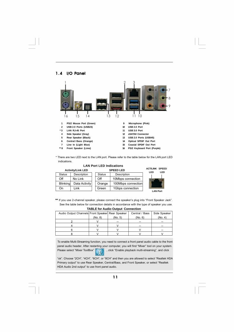
1 .41 .41 .41 .41 .4 I/O PI/O PI/O PI/O PI/O Panelanelanelanelanel
** If you use 2-channel speaker, please connect the speaker’s plug into “Front Speaker Jack”. See the table below for connection details in accordance with the type of speaker you use.
TABLE for Audio Output ConnectionAudio Output Channels Front Speaker Rear Speaker Central / Bass Side Speaker
(No. 8) (No. 5) (No. 6) (No. 4)2 V -- -- --4 V V -- --6 V V V --8 V V V V
LAN Port
ACT/LINK LED
SPEED LED
* There are two LED next to the LAN port. Please refer to the table below for the LAN port LED indications.
LAN Port LED Indications Activity/Link LED SPEED LEDStatus Description Status DescriptionOff No Link Off 10Mbps connectionBlinking Data Activity Orange 100Mbps connectionOn Link Green 1Gbps connection
To enable Multi-Streaming function, you need to connect a front panel audio cable to the front panel audio header. After restarting your computer, you will find “Mixer” tool on your system. Please select “Mixer ToolBox” , click “Enable playback multi-streaming”, and click
“ok”. Choose “2CH”, “4CH”, “6CH”, or “8CH” and then you are allowed to select “Realtek HDA Primary output” to use Rear Speaker, Central/Bass, and Front Speaker, or select “Realtek HDA Audio 2nd output” to use front panel audio.
1 2
4
3
5
6
7
8
9
10111213141516
1 PS/2 Mouse Port (Green) 9 Microphone (Pink)2 USB 2.0 Ports (USB23) 10 USB 2.0 Port
* 3 LAN RJ-45 Port 11 USB 3.0 Port4 Side Speaker (Gray) 12 eSATAII Connector5 Rear Speaker (Black) 13 USB 2.0 Ports (USB45)6 Central / Bass (Orange) 14 Optical SPDIF Out Port7 Line In (Light Blue) 15 Coaxial SPDIF Out Port
** 8 Front Speaker (Lime) 16 PS/2 Keyboard Port (Purple)
1 21 21 21 21 2
2.2.2.2.2. InstallationInstallationInstallationInstallationInstallationThis is an ATX form factor (12.0-in x 8.2-in, 30.5 cm x 20.8 cm) motherboard.Before you install the motherboard, study the configuration of your chassis to en-sure that the motherboard fits into it.
Pre-installation PrecautionsPre-installation PrecautionsPre-installation PrecautionsPre-installation PrecautionsPre-installation PrecautionsTake note of the following precautions before you install motherboardcomponents or change any motherboard settings.
Before you install or remove any component, ensure that thepower is switched off or the power cord is detached from thepower supply. Failure to do so may cause severe damage to themotherboard, peripherals, and/or components.
1. Unplug the power cord from the wall socket before touching anycomponent.
2. To avoid damaging the motherboard components due to staticelectricity, NEVER place your motherboard directly on the carpet orthe like. Also remember to use a grounded wrist strap or touch asafety grounded object before you handle components.
3. Hold components by the edges and do not touch the ICs.4. Whenever you uninstall any component, place it on a grounded anti-
static pad or in the bag that comes with the component.5. When placing screws into the screw holes to secure the motherboard
to the chassis, please do not over-tighten the screws! Doing so maydamage the motherboard.
1 31 31 31 31 3
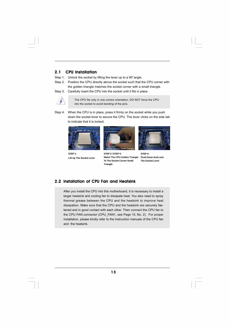
2.12.12.12.12.1 CPU InstallationCPU InstallationCPU InstallationCPU InstallationCPU InstallationStep 1. Unlock the socket by lifting the lever up to a 90o angle.Step 2. Position the CPU directly above the socket such that the CPU corner with
the golden triangle matches the socket corner with a small triangle.Step 3. Carefully insert the CPU into the socket until it fits in place.
The CPU fits only in one correct orientation. DO NOT force the CPUinto the socket to avoid bending of the pins.
Step 4. When the CPU is in place, press it firmly on the socket while you pushdown the socket lever to secure the CPU. The lever clicks on the side tabto indicate that it is locked.
2.22.22.22.22.2 Installation of CPU Fan and HeatsinkInstallation of CPU Fan and HeatsinkInstallation of CPU Fan and HeatsinkInstallation of CPU Fan and HeatsinkInstallation of CPU Fan and Heatsink
After you install the CPU into this motherboard, it is necessary to install alarger heatsink and cooling fan to dissipate heat. You also need to spraythermal grease between the CPU and the heatsink to improve heatdissipation. Make sure that the CPU and the heatsink are securely fas-tened and in good contact with each other. Then connect the CPU fan tothe CPU FAN connector (CPU_FAN1, see Page 10, No. 2). For properinstallation, please kindly refer to the instruction manuals of the CPU fanand the heatsink.
STEP 1:
Lift Up The Socket Lever
STEP 2 / STEP 3:Match The CPU Golden TriangleTo The Socket Corner SmallTriangle
STEP 4:Push Down And LockThe Socket Lever
Lever 90° Up
CPU Golden Triangle
Socker Corner Small Triangle
1 41 41 41 41 4
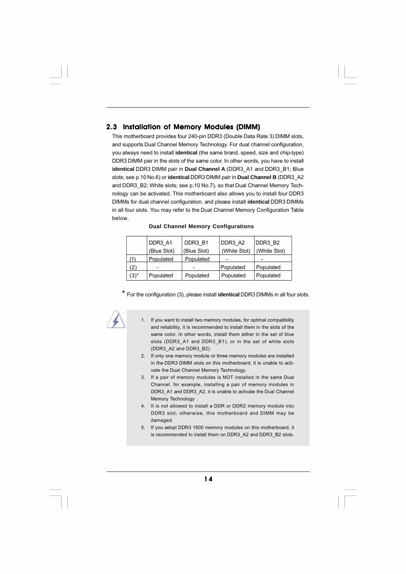
2.3 Installation of Memory Modules (DIMM)2.3 Installation of Memory Modules (DIMM)2.3 Installation of Memory Modules (DIMM)2.3 Installation of Memory Modules (DIMM)2.3 Installation of Memory Modules (DIMM)This motherboard provides four 240-pin DDR3 (Double Data Rate 3) DIMM slots,and supports Dual Channel Memory Technology. For dual channel configuration,you always need to install identical (the same brand, speed, size and chip-type)DDR3 DIMM pair in the slots of the same color. In other words, you have to installidentical DDR3 DIMM pair in Dual Channel A (DDR3_A1 and DDR3_B1; Blueslots; see p.10 No.6) or identical DDR3 DIMM pair in Dual Channel B (DDR3_A2and DDR3_B2; White slots; see p.10 No.7), so that Dual Channel Memory Tech-nology can be activated. This motherboard also allows you to install four DDR3DIMMs for dual channel configuration, and please install identical DDR3 DIMMsin all four slots. You may refer to the Dual Channel Memory Configuration Tablebelow.
Dual Channel Memory Configurations
DDR3_A1 DDR3_B1 DDR3_A2 DDR3_B2(Blue Slot) (Blue Slot) (White Slot) (White Slot)
(1) Populated Populated - -(2) - - Populated Populated(3)* Populated Populated Populated Populated
* For the configuration (3), please install identical DDR3 DIMMs in all four slots.
1. If you want to install two memory modules, for optimal compatibilityand reliability, it is recommended to install them in the slots of thesame color. In other words, install them either in the set of blueslots (DDR3_A1 and DDR3_B1), or in the set of white slots(DDR3_A2 and DDR3_B2).
2. If only one memory module or three memory modules are installedin the DDR3 DIMM slots on this motherboard, it is unable to acti-vate the Dual Channel Memory Technology.
3. If a pair of memory modules is NOT installed in the same DualChannel, for example, installing a pair of memory modules inDDR3_A1 and DDR3_A2, it is unable to activate the Dual ChannelMemory Technology .
4. It is not allowed to install a DDR or DDR2 memory module intoDDR3 slot; otherwise, this motherboard and DIMM may bedamaged.
5. If you adopt DDR3 1600 memory modules on this motherboard, itis recommended to install them on DDR3_A2 and DDR3_B2 slots.
1 51 51 51 51 5
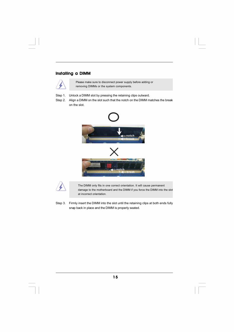
notch
break
notchbreak
Installing a DIMMInstalling a DIMMInstalling a DIMMInstalling a DIMMInstalling a DIMM
Please make sure to disconnect power supply before adding orremoving DIMMs or the system components.
Step 1. Unlock a DIMM slot by pressing the retaining clips outward.Step 2. Align a DIMM on the slot such that the notch on the DIMM matches the break
on the slot.
The DIMM only fits in one correct orientation. It will cause permanentdamage to the motherboard and the DIMM if you force the DIMM into the slotat incorrect orientation.
Step 3. Firmly insert the DIMM into the slot until the retaining clips at both ends fullysnap back in place and the DIMM is properly seated.
1 61 61 61 61 6
2.4 Expansion Slots (PCI and PCI Express Slots)2.4 Expansion Slots (PCI and PCI Express Slots)2.4 Expansion Slots (PCI and PCI Express Slots)2.4 Expansion Slots (PCI and PCI Express Slots)2.4 Expansion Slots (PCI and PCI Express Slots)There are 3 PCI slots and 3 PCI Express slots on this motherboard.PCI Slots: PCI slots are used to install expansion cards that have the 32-bit PCI
interface.PCIE Slots:
PCIE1 / PCIE3 (PCIE x1 slot; White) is used for PCI Express cards withx1 lane width cards, such as Gigabit LAN card and SATA2 card.PCIE2 (PCIE x16 slot; Blue) is used for PCI Express x16 lane widthgraphics cards.
Installing an expansion cardInstalling an expansion cardInstalling an expansion cardInstalling an expansion cardInstalling an expansion cardStep 1. Before installing the expansion card, please make sure that the power
supply is switched off or the power cord is unplugged. Please read thedocumentation of the expansion card and make necessary hardwaresettings for the card before you start the installation.
Step 2. Remove the system unit cover (if your motherboard is already installed in achassis).
Step 3. Remove the bracket facing the slot that you intend to use. Keep the screwsfor later use.
Step 4. Align the card connector with the slot and press firmly until the card iscompletely seated on the slot.
Step 5. Fasten the card to the chassis with screws.Step 6. Replace the system cover.
1 71 71 71 71 7
+5V
1_2
+5VSB
2_3
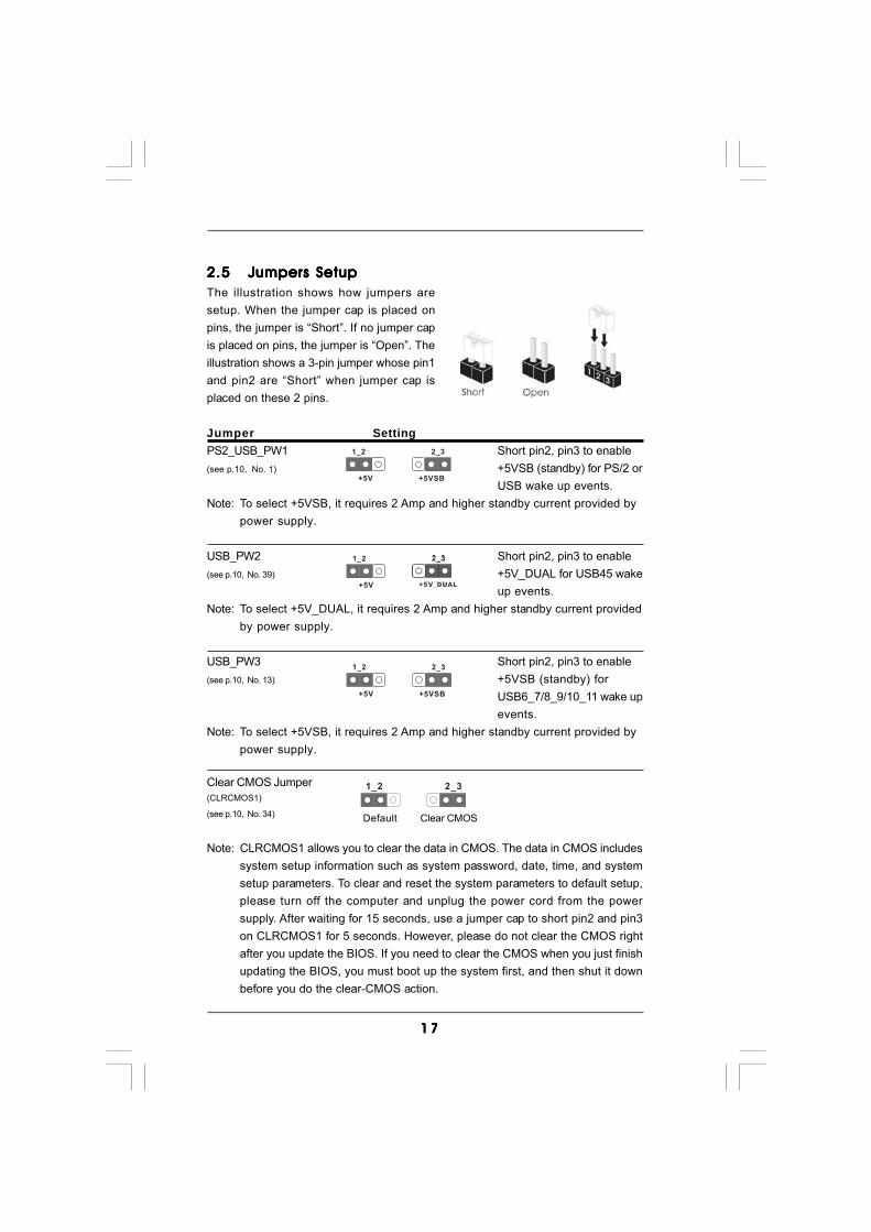
2.52.52.52.52.5 Jumpers SetupJumpers SetupJumpers SetupJumpers SetupJumpers SetupThe illustration shows how jumpers aresetup. When the jumper cap is placed onpins, the jumper is “Short”. If no jumper capis placed on pins, the jumper is “Open”. Theillustration shows a 3-pin jumper whose pin1and pin2 are “Short” when jumper cap isplaced on these 2 pins.
Jumper SettingPS2_USB_PW1 Short pin2, pin3 to enable(see p.10, No. 1) +5VSB (standby) for PS/2 or
USB wake up events.Note: To select +5VSB, it requires 2 Amp and higher standby current provided by
power supply.
USB_PW2 Short pin2, pin3 to enable(see p.10, No. 39) +5V_DUAL for USB45 wake
up events.Note: To select +5V_DUAL, it requires 2 Amp and higher standby current provided
by power supply.
USB_PW3 Short pin2, pin3 to enable(see p.10, No. 13) +5VSB (standby) for
USB6_7/8_9/10_11 wake upevents.
Note: To select +5VSB, it requires 2 Amp and higher standby current provided bypower supply.
Clear CMOS Jumper(CLRCMOS1)
(see p.10, No. 34)
Note: CLRCMOS1 allows you to clear the data in CMOS. The data in CMOS includessystem setup information such as system password, date, time, and systemsetup parameters. To clear and reset the system parameters to default setup,please turn off the computer and unplug the power cord from the powersupply. After waiting for 15 seconds, use a jumper cap to short pin2 and pin3on CLRCMOS1 for 5 seconds. However, please do not clear the CMOS rightafter you update the BIOS. If you need to clear the CMOS when you just finishupdating the BIOS, you must boot up the system first, and then shut it downbefore you do the clear-CMOS action.
Clear CMOS
2_31_2
Default
+5V
1_2
+5VSB
2_3
+5V
1_2
+5V_DUAL
1 81 81 81 81 8
FLOPPY1Pin1
the red-striped side to Pin1
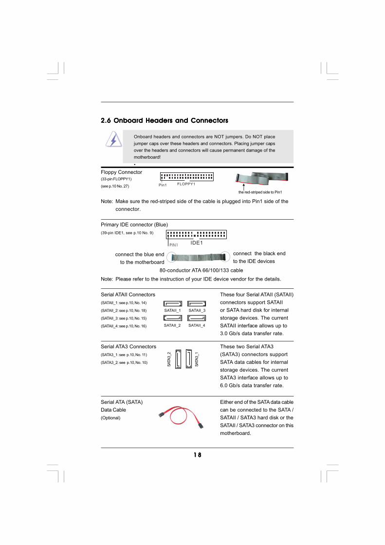
2.6 Onboard Headers and Connectors2.6 Onboard Headers and Connectors2.6 Onboard Headers and Connectors2.6 Onboard Headers and Connectors2.6 Onboard Headers and Connectors
Onboard headers and connectors are NOT jumpers. Do NOT placejumper caps over these headers and connectors. Placing jumper capsover the headers and connectors will cause permanent damage of themotherboard!•
Floppy Connector(33-pin FLOPPY1)
(see p.10 No. 27)
Note: Make sure the red-striped side of the cable is plugged into Pin1 side of theconnector.
Primary IDE connector (Blue)(39-pin IDE1, see p.10 No. 9)
Note: Please refer to the instruction of your IDE device vendor for the details.
Serial ATAII Connectors These four Serial ATAII (SATAII)(SATAII_1: see p.10, No. 14) connectors support SATAII(SATAII_2: see p.10, No. 18) or SATA hard disk for internal(SATAII_3: see p.10, No. 15) storage devices. The current(SATAII_4: see p.10, No. 16) SATAII interface allows up to
3.0 Gb/s data transfer rate.
connect the black endto the IDE devices
connect the blue endto the motherboard
IDE1PIN1
80-conductor ATA 66/100/133 cable
SATAII_1 SATAII_3
SATAII_2 SATAII_4
Serial ATA (SATA) Either end of the SATA data cableData Cable can be connected to the SATA /(Optional) SATAII / SATA3 hard disk or the
SATAII / SATA3 connector on thismotherboard.
Serial ATA3 Connectors These two Serial ATA3(SATA3_1: see p.10, No. 11) (SATA3) connectors support(SATA3_2: see p.10, No. 10) SATA data cables for internal
storage devices. The currentSATA3 interface allows up to6.0 Gb/s data transfer rate.
SATA
3_1
SATA
3_2
1 91 91 91 91 9
CD
-L
GN
DG
ND
CD
-R
CD1
Internal Audio Connectors This connector allows you(4-pin CD1) to receive stereo audio input(CD1: see p.10 No. 30) from sound sources such as
a CD-ROM, DVD-ROM, TVtuner card, or MPEG card.
J_SENSE
OUT2_L
1
MIC_RETPRESENCE#
GND
OUT2_RMIC2_R
MIC2_L
OUT_RET
Front Panel Audio Header This is an interface for the front(9-pin HD_AUDIO1) panel audio cable that allows(see p.10, No. 29) convenient connection and
control of audio devices.
USB 2.0 Headers Besides five default USB 2.0(9-pin USB10_11) ports on the I/O panel, there are(see p.10 No. 23) three USB 2.0 headers on this
motherboard. Each USB 2.0header can support two USB2.0 ports.
(9-pin USB8_9)(see p.10 No. 21)
(9-pin USB6_7)(see p.10 No. 22)
Infrared Module Header This header supports an(5-pin IR1) optional wireless transmitting(see p.10 No. 26) and receiving infrared module.
DUMMY
GND
+5VIRTX
IRRX
1
USB_PWR
USB_PWR
P+7P-7
P+6P-6
GND
GND
DUMMY
1
1
USB_PWRP-8
GND
DUMMY
USB_PWR
P+8
GND
P-9P+9
1
USB_PWRP-10
GND
DUMMY
USB_PWR
P+10
GND
P-11P+11
Serial ATA (SATA) Please connect the black end ofPower Cable SATA power cable to the power(Optional) connector on each drive. Then
connect the white end of SATApower cable to the powerconnector of the power supply.
connect to the SATA HDDpower connector
connect to thepower supply

2 02 02 02 02 0
GND
PWRBTN#PLED-
PLED+
DUMMYRESET#
GND
HDLED+HDLED-
1
System Panel Header This header accommodates(9-pin PANEL1) several system front panel(see p.10 No. 24) functions.
1. High Definition Audio supports Jack Sensing, but the panel wire on the chassis must support HDA to function correctly. Please follow the
instruction in our manual and chassis manual to install your system.2. If you use AC’97 audio panel, please install it to the front panel audio header as below: A. Connect Mic_IN (MIC) to MIC2_L. B. Connect Audio_R (RIN) to OUT2_R and Audio_L (LIN) to OUT2_L.
C. Connect Ground (GND) to Ground (GND). D. MIC_RET and OUT_RET are for HD audio panel only. You don’t need to connect them for AC’97 audio panel. E. Enter BIOS Setup Utility. Enter Advanced Settings, and then select
Chipset Configuration. Set the Front Panel Control option from [Auto] to [Enabled]. F. Enter Windows system. Click the icon on the lower right hand taskbar to enter Realtek HD Audio Manager. For Windows® XP / XP 64-bit OS: Click “Audio I/O”, select “Connector Settings” , choose
“Disable front panel jack detection”, and save the change by clicking “OK”. For Windows® 7 / 7 64-bit / VistaTM / VistaTM 64-bit OS: Click the right-top “Folder” icon , choose “Disable front
panel jack detection”, and save the change by clicking “OK”. G. To activate the front mic. For Windows® XP / XP 64-bit OS: Please select “Front Mic” as default record device. If you want to hear your voice through front mic, please deselect "Mute" icon in “Front Mic” of “Playback” portion. For Windows® 7 / 7 64-bit / VistaTM / VistaTM 64-bit OS: Go to the "Front Mic" Tab in the Realtek Control panel. Click "Set Default Device" to make the Front Mic as the default record device.
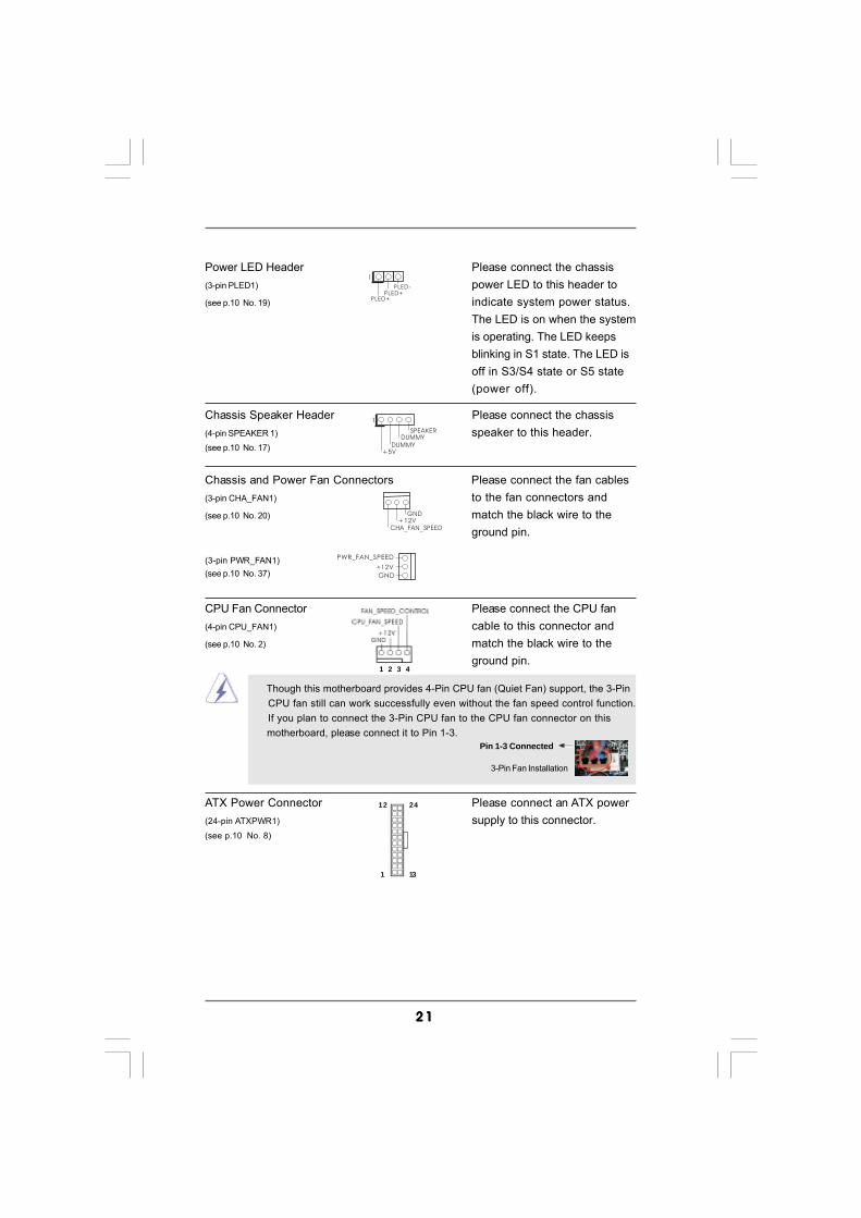
2 12 12 12 12 1
CPU Fan Connector Please connect the CPU fan(4-pin CPU_FAN1) cable to this connector and(see p.10 No. 2) match the black wire to the
ground pin.
Though this motherboard provides 4-Pin CPU fan (Quiet Fan) support, the 3-Pin CPU fan still can work successfully even without the fan speed control function. If you plan to connect the 3-Pin CPU fan to the CPU fan connector on this motherboard, please connect it to Pin 1-3.
3-Pin Fan Installation
Pin 1-3 Connected
+5V
DUMMYDUMMY
SPEAKER
1
Chassis and Power Fan Connectors Please connect the fan cables(3-pin CHA_FAN1) to the fan connectors and(see p.10 No. 20) match the black wire to the
ground pin.
(3-pin PWR_FAN1)(see p.10 No. 37)
GND+12V
CHA_FAN_SPEED
GND
+12V
PWR_FAN_SPEED
ATX Power Connector Please connect an ATX power(24-pin ATXPWR1) supply to this connector.(see p.10 No. 8)
12
1
24
13
Chassis Speaker Header Please connect the chassis(4-pin SPEAKER 1) speaker to this header.(see p.10 No. 17)
Power LED Header Please connect the chassis(3-pin PLED1) power LED to this header to(see p.10 No. 19) indicate system power status.
The LED is on when the systemis operating. The LED keepsblinking in S1 state. The LED isoff in S3/S4 state or S5 state(power off).
1
PLED+PLED+
PLED-
1 2 3 4
2 22 22 22 22 2
20-Pin ATX Power Supply Installation
Though this motherboard provides 24-pin ATX power connector, it can still work if you adopt a traditional 20-pin ATX power supply. To use the 20-pin ATX power supply, please plug your power supply along with Pin 1 and Pin 13.
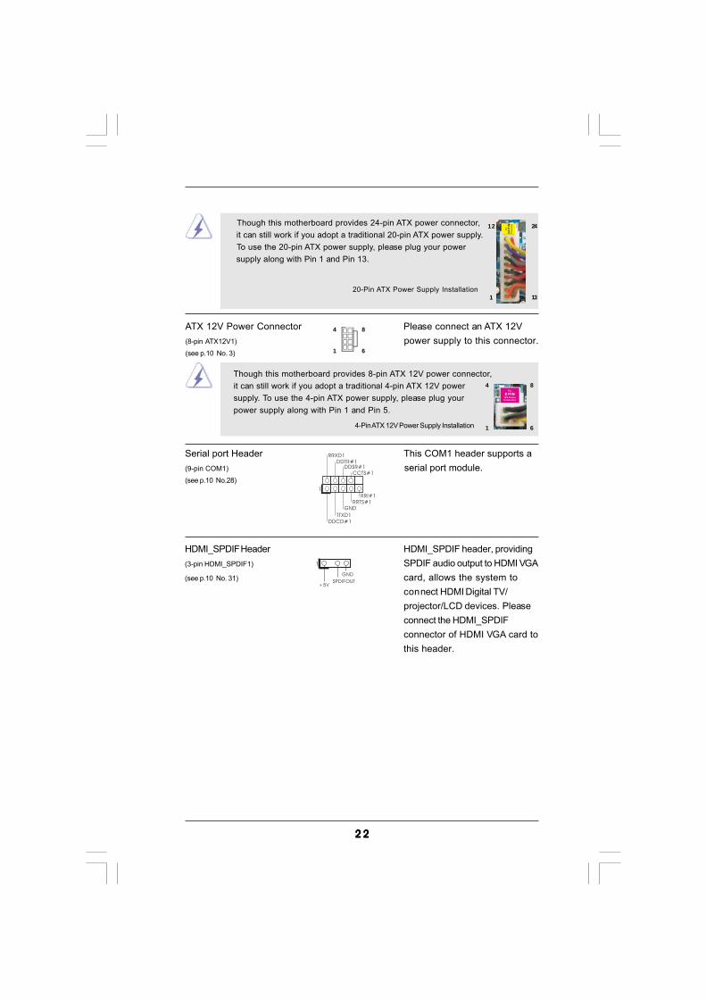
Serial port Header This COM1 header supports a(9-pin COM1) serial port module.(see p.10 No.28)
CCTS#1DDSR#1
DDTR#1RRXD1
DDCD#1TTXD1
GNDRRTS#1
RRI#1
1
ATX 12V Power Connector Please connect an ATX 12V(8-pin ATX12V1) power supply to this connector.(see p.10 No. 3)
4-Pin ATX 12V Power Supply Installation
Though this motherboard provides 8-pin ATX 12V power connector,it can still work if you adopt a traditional 4-pin ATX 12V powersupply. To use the 4-pin ATX power supply, please plug yourpower supply along with Pin 1 and Pin 5.
4 8
1 6
4 8
1 6
HDMI_SPDIF Header HDMI_SPDIF header, providing(3-pin HDMI_SPDIF1) SPDIF audio output to HDMI VGA(see p.10 No. 31) card, allows the system to
connect HDMI Digital TV/projector/LCD devices. Pleaseconnect the HDMI_SPDIFconnector of HDMI VGA card tothis header.
1
GND
+5VSPDIFOUT
12
1
24
13
2 32 32 32 32 3
CB
GND
+5V
SPDIFOUT blue
black
blue
blackGND
SPDIFOUT blue
blackGND
SPDIFOUT
A
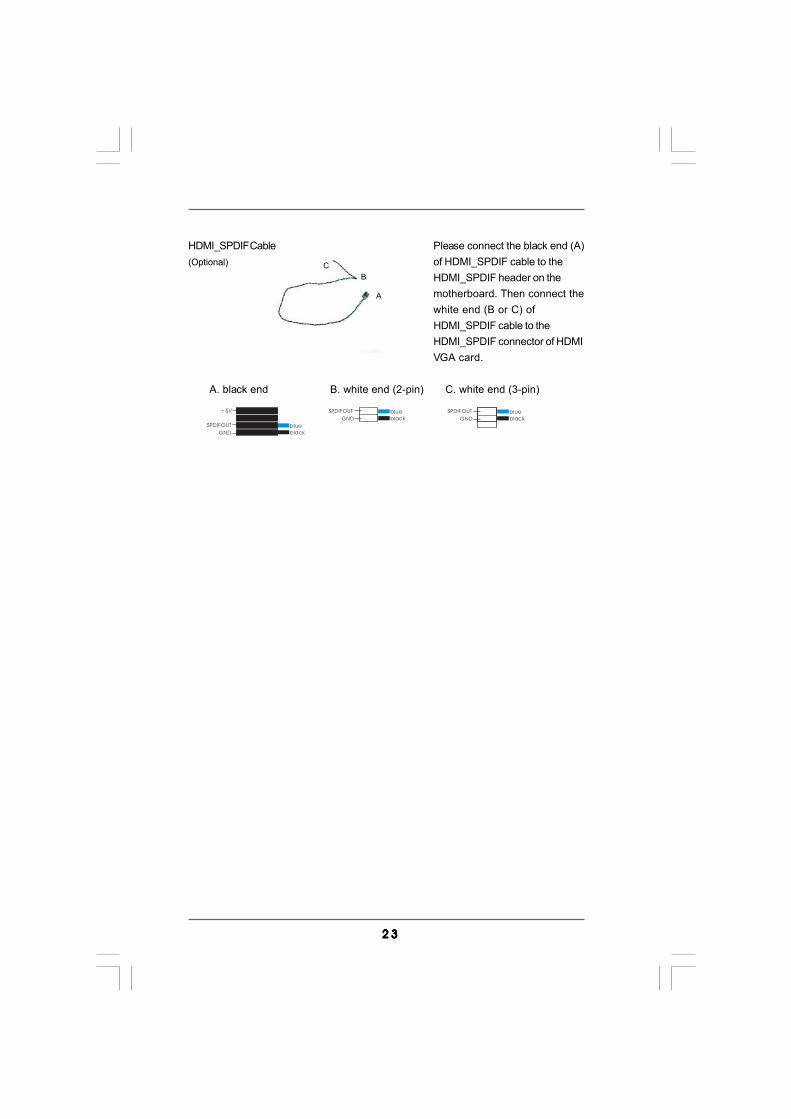
HDMI_SPDIF Cable Please connect the black end (A)(Optional) of HDMI_SPDIF cable to the
HDMI_SPDIF header on themotherboard. Then connect thewhite end (B or C) ofHDMI_SPDIF cable to theHDMI_SPDIF connector of HDMIVGA card.
A. black end B. white end (2-pin) C. white end (3-pin)
2 42 42 42 42 4
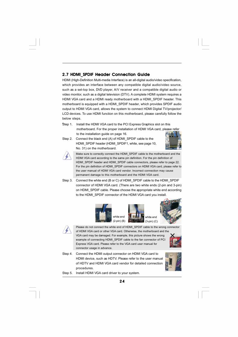
2.7 HDMI_SPDIF Header Connection Guide2.7 HDMI_SPDIF Header Connection Guide2.7 HDMI_SPDIF Header Connection Guide2.7 HDMI_SPDIF Header Connection Guide2.7 HDMI_SPDIF Header Connection GuideHDMI (High-Definition Multi-media Interface) is an all-digital audio/video specification,which provides an interface between any compatible digital audio/video source,such as a set-top box, DVD player, A/V receiver and a compatible digital audio orvideo monitor, such as a digital television (DTV). A complete HDMI system requires aHDMI VGA card and a HDMI ready motherboard with a HDMI_SPDIF header. Thismotherboard is equipped with a HDMI_SPDIF header, which provides SPDIF audiooutput to HDMI VGA card, allows the system to connect HDMI Digital TV/projector/LCD devices. To use HDMI function on this motherboard, please carefully follow thebelow steps.•
Make sure to correctly connect the HDMI_SPDIF cable to the motherboard and theHDMI VGA card according to the same pin definition. For the pin definition ofHDMI_SPDIF header and HDMI_SPDIF cable connectors, please refer to page 22.For the pin definition of HDMI_SPDIF connectors on HDMI VGA card, please refer tothe user manual of HDMI VGA card vendor. Incorrect connection may causepermanent damage to this motherboard and the HDMI VGA card.
white end(2-pin) (B)
white end(3-pin) (C)
Please do not connect the white end of HDMI_SPDIF cable to the wrong connectorof HDMI VGA card or other VGA card. Otherwise, the motherboard and theVGA card may be damaged. For example, this picture shows the wrongexample of connecting HDMI_SPDIF cable to the fan connector of PCIExpress VGA card. Please refer to the VGA card user manual forconnector usage in advance.
Step 4. Connect the HDMI output connector on HDMI VGA card toHDMI device, such as HDTV. Please refer to the user manualof HDTV and HDMI VGA card vendor for detailed connectionprocedures.
Step 5. Install HDMI VGA card driver to your system.
Step 3. Connect the white end (B or C) of HDMI_SPDIF cable to the HDMI_SPDIFconnector of HDMI VGA card. (There are two white ends (2-pin and 3-pin)on HDMI_SPDIF cable. Please choose the appropriate white end accordingto the HDMI_SPDIF connector of the HDMI VGA card you install.
Step 1. Install the HDMI VGA card to the PCI Express Graphics slot on this motherboard. For the proper installation of HDMI VGA card, please refer to the installation guide on page 16.
Step 2. Connect the black end (A) of HDMI_SPDIF cable to theHDMI_SPDIF header (HDMI_SPDIF1, white, see page 10,No. 31) on the motherboard.
2 52 52 52 52 5
2.82.82.82.82.8 Serial ASerial ASerial ASerial ASerial ATTTTTA (SAA (SAA (SAA (SAA (SATTTTTA) / Serial AA) / Serial AA) / Serial AA) / Serial AA) / Serial ATTTTTAII (SAAII (SAAII (SAAII (SAAII (SATTTTTAII) Hard DisksAII) Hard DisksAII) Hard DisksAII) Hard DisksAII) Hard Disks
Instal lat ionInstal lat ionInstal lat ionInstal lat ionInstal lat ionThis motherboard adopts AMD SB710 south bridge chipset that supports Serial
ATA (SATA) / Serial ATAII (SATAII) hard disks and RAID (RAID 0, RAID 1, RAID 10
and JBOD) functions. You may install SATA / SATAII hard disks on this
motherboard for internal storage devices. This section will guide you to install the
SATA / SATAII hard disks.
STEP 1: Install the SATA / SATAII hard disks into the drive bays of your chassis.
STEP 2: Connect the SATA power cable to the SATA / SATAII hard disk.
STEP 3: Connect one end of the SATA data cable to the motherboard’s SATAII
connector.
STEP 4: Connect the other end of the SATA data cable to the SATA / SATAII hard
disk.
If you plan to use RAID 0 or RAID 1 function, you need to install at least 2
SATA / SATAII hard disks. If you plan to use RAID 10 function, you need to
install at least 4 SATA / SATAII hard disks.
2.92.92.92.92.9 Serial ASerial ASerial ASerial ASerial ATTTTTA3 (SAA3 (SAA3 (SAA3 (SAA3 (SATTTTTA3) Hard Disks InstallationA3) Hard Disks InstallationA3) Hard Disks InstallationA3) Hard Disks InstallationA3) Hard Disks InstallationThis motherboard adopts Marvell SE9123/9120 chipset that supports Serial ATA3
(SATA3) hard disks. You may install SATA3 hard disks on this motherboard for
internal storage devices. This section will guide you to install the SATA3 hard
disks.
STEP 1: Install the SATA3 hard disks into the drive bays of your chassis.
STEP 2: Connect the SATA power cable to the SATA3 hard disk.
STEP 3: Connect one end of the SATA data cable to the motherboard’s SATA3
connector.
STEP 4: Connect the other end of the SATA data cable to the SATA3 hard disk.
It is not recommended to switch the “Marvell SATA3 Operation Mode” setting
between AHCI and IDE mode after OS installation.
2 62 62 62 62 6
2.10 Hot Plug and Hot Swap F2.10 Hot Plug and Hot Swap F2.10 Hot Plug and Hot Swap F2.10 Hot Plug and Hot Swap F2.10 Hot Plug and Hot Swap Functions for SAunctions for SAunctions for SAunctions for SAunctions for SATTTTTA / SAA / SAA / SAA / SAA / SATTTTTAIIAIIAIIAIIAII
HDDs HDDs HDDs HDDs HDDsThis motherboard supports Hot Plug and Hot Swap functions for SATA / SATAII
Devices in RAID / AHCI mode. AMD SB710 south bridge chipset provides hardware
support for Advanced Host controller Interface (AHCI), a new programming interface
for SATA host controllers developed thru a joint industry effort. AHCI also provides
usability enhancements such as Hot Plug.
NOTEWhat is Hot Plug Function?If the SATA / SATAII HDDs are NOT set for RAID configuration, it is called
“Hot Plug” for the action to insert and remove the SATA / SATAII HDDs
while the system is still power-on and in working condition.
However, please note that it cannot perform Hot Plug if the OS has been
installed into the SATA / SATAII HDD.
What is Hot Swap Function?If SATA / SATAII HDDs are built as RAID 1 then it is called “Hot Swap” for
the action to insert and remove the SATA / SATAII HDDs while the system
is still power-on and in working condition.
2.11 Hot Plug F2.11 Hot Plug F2.11 Hot Plug F2.11 Hot Plug F2.11 Hot Plug Function for SAunction for SAunction for SAunction for SAunction for SATTTTTA3 HDDsA3 HDDsA3 HDDsA3 HDDsA3 HDDsThis motherboard supports Hot Plug and Hot Swap functions for SATA3 in AHCI
mode. Marvell SE9123/9120 chipset provides hardware support for Advanced Host
controller Interface (AHCI), a new programming interface for SATA host controllers
developed thru a joint industry effort.
NOTEWhat is Hot Plug Function?If the SATA3 HDDs are NOT set for RAID configuration, it is called “Hot
Plug” for the action to insert and remove the SATA3 HDDs while the
system is still power-on and in working condition.
However, please note that it cannot perform Hot Plug if the OS has been
installed into the SATA3 HDD.
2 72 72 72 72 7
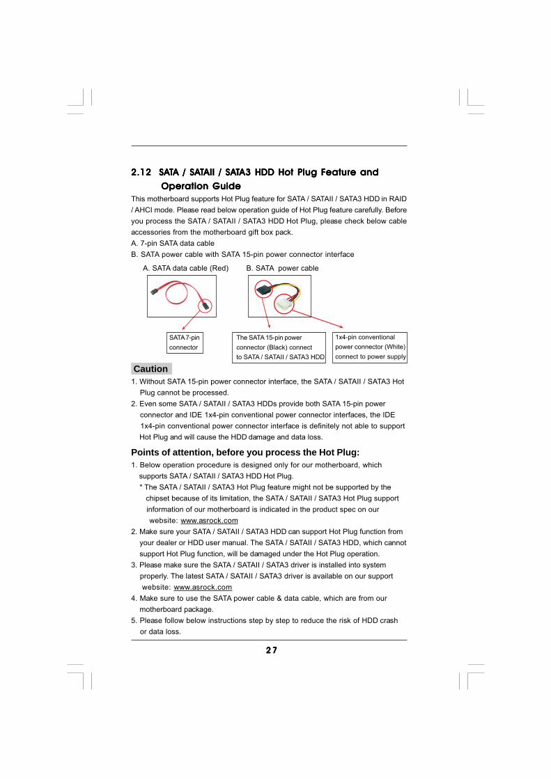
Caution1. Without SATA 15-pin power connector interface, the SATA / SATAII / SATA3 Hot Plug cannot be processed.2. Even some SATA / SATAII / SATA3 HDDs provide both SATA 15-pin power connector and IDE 1x4-pin conventional power connector interfaces, the IDE 1x4-pin conventional power connector interface is definitely not able to support Hot Plug and will cause the HDD damage and data loss.
SATA 7-pinconnector
1x4-pin conventionalpower connector (White)connect to power supply
A. SATA data cable (Red) B. SATA power cable
2.12 SA2.12 SA2.12 SA2.12 SA2.12 SATTTTTA / SAA / SAA / SAA / SAA / SATTTTTAII / SAAII / SAAII / SAAII / SAAII / SATTTTTA3 HDD Hot Plug FA3 HDD Hot Plug FA3 HDD Hot Plug FA3 HDD Hot Plug FA3 HDD Hot Plug Feature andeature andeature andeature andeature and
Operation Guide Operation Guide Operation Guide Operation Guide Operation GuideThis motherboard supports Hot Plug feature for SATA / SATAII / SATA3 HDD in RAID/ AHCI mode. Please read below operation guide of Hot Plug feature carefully. Beforeyou process the SATA / SATAII / SATA3 HDD Hot Plug, please check below cableaccessories from the motherboard gift box pack.A. 7-pin SATA data cableB. SATA power cable with SATA 15-pin power connector interface
The SATA 15-pin powerconnector (Black) connectto SATA / SATAII / SATA3 HDD
Points of attention, before you process the Hot Plug:1. Below operation procedure is designed only for our motherboard, which supports SATA / SATAII / SATA3 HDD Hot Plug. * The SATA / SATAII / SATA3 Hot Plug feature might not be supported by the chipset because of its limitation, the SATA / SATAII / SATA3 Hot Plug support information of our motherboard is indicated in the product spec on our website: www.asrock.com2. Make sure your SATA / SATAII / SATA3 HDD can support Hot Plug function from your dealer or HDD user manual. The SATA / SATAII / SATA3 HDD, which cannot support Hot Plug function, will be damaged under the Hot Plug operation.3. Please make sure the SATA / SATAII / SATA3 driver is installed into system properly. The latest SATA / SATAII / SATA3 driver is available on our support website: www.asrock.com4. Make sure to use the SATA power cable & data cable, which are from our motherboard package.5. Please follow below instructions step by step to reduce the risk of HDD crash or data loss.
2 82 82 82 82 8
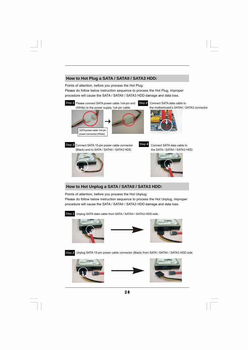
How to Hot Plug a SATA / SATAII / SATA3 HDD:Points of attention, before you process the Hot Plug:Please do follow below instruction sequence to process the Hot Plug, improperprocedure will cause the SATA / SATAII / SATA3 HDD damage and data loss.
Connect SATA data cable tothe motherboard’s SATAII / SATA3 connector.
Connect SATA 15-pin power cable connector(Black) end to SATA / SATAII / SATA3 HDD.
Connect SATA data cable tothe SATA / SATAII / SATA3 HDD.
How to Hot Unplug a SATA / SATAII / SATA3 HDD:
Points of attention, before you process the Hot Unplug:Please do follow below instruction sequence to process the Hot Unplug, improperprocedure will cause the SATA / SATAII / SATA3 HDD damage and data loss.
Please connect SATA power cable 1x4-pin end(White) to the power supply 1x4-pin cable.
Step 1 Step 2
Step 3 Step 4
Step 2
SATA power cable 1x4-pinpower connector (White)
Unplug SATA data cable from SATA / SATAII / SATA3 HDD side.
Unplug SATA 15-pin power cable connector (Black) from SATA / SATAII / SATA3 HDD side.
Step 1
2 92 92 92 92 9
2.132.132.132.132.13 Driver Installation GuideDriver Installation GuideDriver Installation GuideDriver Installation GuideDriver Installation GuideTo install the drivers to your system, please insert the support CD to your opticaldrive first. Then, the drivers compatible to your system can be auto-detected andlisted on the support CD driver page. Please follow the order from up to bottomside to install those required drivers. Therefore, the drivers you install can workproperly.
2.142.142.142.142.14 Installing WindowsInstalling WindowsInstalling WindowsInstalling WindowsInstalling Windows®®®®® 7 / 7 64-bit / Vista 7 / 7 64-bit / Vista 7 / 7 64-bit / Vista 7 / 7 64-bit / Vista 7 / 7 64-bit / VistaTMTMTMTMTM / / / / /
VistaVistaVistaVistaVistaTMTMTMTMTM 64-bit / XP / XP 64-bit With RAID Functions 64-bit / XP / XP 64-bit With RAID Functions 64-bit / XP / XP 64-bit With RAID Functions 64-bit / XP / XP 64-bit With RAID Functions 64-bit / XP / XP 64-bit With RAID FunctionsIf you want to install Windows® 7 / 7 64-bit / VistaTM / VistaTM 64-bit / XP / XP 64-bit ona RAID disk composed of 2 or more SATA / SATAII HDDs with RAID functions, pleasefollow below procedures according to the OS you install.
2.14.1 Installing Windows2.14.1 Installing Windows2.14.1 Installing Windows2.14.1 Installing Windows2.14.1 Installing Windows®®®®® XP / XP 64-bit With RAID XP / XP 64-bit With RAID XP / XP 64-bit With RAID XP / XP 64-bit With RAID XP / XP 64-bit With RAID
F F F F FunctionsunctionsunctionsunctionsunctionsIf you want to install Windows® XP / XP 64-bit on a RAID disk composed of 2 or moreSATA / SATAII HDDs with RAID functions, please follow below steps.
STEP 1: Set up BIOS.A. Enter BIOS SETUP UTILITY Advanced screen Storage
Configuration.B. Set the “SATA Operation Mode” option to [RAID].STEP 2: Make a SATA / SATAII Driver Diskette.A. Insert the ASRock Support CD into your optical drive to boot your system.B. During POST at the beginning of system boot-up, press <F11> key, and
then a window for boot devices selection appears. Please select CD-ROMas the boot device.
C. When you see the message on the screen, “Generate Serial ATA driverdiskette [YN]?”, press <Y>.
D. Then you will see these messages,Please insert a blankformatted diskette into floppydrive A:press any key to start
Please insert a floppy diskette into the floppy drive, and press any key.E. The system will start to format the floppy diskette and copy SATA / SATAII
drivers into the floppy diskette.
3 03 03 03 03 0
NOTE. If you install Windows® XP / XP 64-bit on IDE HDDs and want to manage(create, convert, delete, or rebuild) RAID functions on SATA / SATAII HDDs, you stillneed to set up “SATA Operation Mode” to [RAID] first. Then, please set the RAIDconfiguration by using the Windows RAID installation guide in the following path inthe Support CD: .. \ RAID Installation Guide
2.14.2 Installing Windows2.14.2 Installing Windows2.14.2 Installing Windows2.14.2 Installing Windows2.14.2 Installing Windows®®®®® 7 / 7 64-bit / Vista 7 / 7 64-bit / Vista 7 / 7 64-bit / Vista 7 / 7 64-bit / Vista 7 / 7 64-bit / VistaTMTMTMTMTM / / / / /
Vista Vista Vista Vista VistaTMTMTMTMTM 64-bit With RAID Functions 64-bit With RAID Functions 64-bit With RAID Functions 64-bit With RAID Functions 64-bit With RAID FunctionsIf you want to install Windows® 7 / 7 64-bit / VistaTM / VistaTM 64-bit on a RAID diskcomposed of 2 or more SATA / SATAII HDDs with RAID functions, please followbelow steps.
STEP 1: Set up BIOS.A. Enter BIOS SETUP UTILITY Advanced screen Storage
Configuration.B. Set the “SATA Operation Mode” option to [RAID].STEP 2: Use “RAID Installation Guide” to set RAID configuration.Before you start to configure RAID function, you need to check the RAID installationguide in the Support CD for proper configuration. Please refer to the BIOS RAID installationguide part of the document in the following path in the Support CD:.. \ RAID Installation GuideSTEP 3: Install Windows® 7 / 7 64-bit / VistaTM / VistaTM 64-bit OS on your system.Insert the Windows® 7 / 7 64-bit / VistaTM / VistaTM 64-bit optical disk into the opticaldrive to boot your system, and follow the instruction to install Windows® 7 / 7 64-bit/ VistaTM / VistaTM 64-bit OS on your system. When you see “Where do you want toinstall Windows?” page, please insert the ASRock Support CD into your optical drive,and click the “Load Driver” button on the left on the bottom to load the AMD RAID
STEP 3: Use “RAID Installation Guide” to set RAID configuration.Before you start to configure RAID function, you need to check the RAID installationguide in the Support CD for proper configuration. Please refer to the BIOS RAID installationguide part of the document in the following path in the Support CD:.. \ RAID Installation GuideSTEP 4: Install Windows® XP / XP 64-bit OS on your system.After step 1, 2, 3, you can start to install Windows® XP / XP 64-bit OS on your system.At the beginning of Windows® setup, press F6 to install a third-party RAID driver.When prompted, insert the SATA / SATAII driver diskette containing the AMD RAIDdriver. After reading the floppy disk, the driver will be presented. Select the driver toinstall according to the OS you install. (Select “AMD AHCI Compatible RAID Controller-x86 platform” for Windows® XP, or “AMD AHCI Compatible RAID Controller-x64 platform”for Windows® XP 64-bit.)
3 13 13 13 13 1
2.152.152.152.152.15 Installing WindowsInstalling WindowsInstalling WindowsInstalling WindowsInstalling Windows®®®®® 7 / 7 64-bit / Vista 7 / 7 64-bit / Vista 7 / 7 64-bit / Vista 7 / 7 64-bit / Vista 7 / 7 64-bit / VistaTMTMTMTMTM / / / / /
Vista Vista Vista Vista VistaTMTMTMTMTM 64-bit / XP / XP 64-bit Without RAID Functions 64-bit / XP / XP 64-bit Without RAID Functions 64-bit / XP / XP 64-bit Without RAID Functions 64-bit / XP / XP 64-bit Without RAID Functions 64-bit / XP / XP 64-bit Without RAID FunctionsIf you want to install Windows® 7 / 7 64-bit / VistaTM / VistaTM 64-bit / XP / XP 64-bit OSon your SATA / SATAII HDDs without RAID functions, please follow below proceduresaccording to the OS you install.
NOTE1. If you install Windows® 7 / 7 64-bit / VistaTM / VistaTM 64-bit on IDE HDDs and want to manage (create, convert, delete, or rebuild) RAID functions on SATA / SATAII HDDs, you still need to set up “SATA Operation Mode” to [RAID] in BIOS first. Then, please set the RAID configuration by using the Windows RAID installation guide in the following path in the Support CD: .. \ RAID Installation Guide
NOTE2. Currently, if you install Windows® 7 / 7 64-bit / VistaTM / VistaTM 64-bit on IDE HDDs and there are no SATA / SATAII device used, please set up “SATA Operation Mode” to [IDE] in BIOS.
2.15.1 Installing Windows2.15.1 Installing Windows2.15.1 Installing Windows2.15.1 Installing Windows2.15.1 Installing Windows®®®®® XP / XP 64-bit Without RAID XP / XP 64-bit Without RAID XP / XP 64-bit Without RAID XP / XP 64-bit Without RAID XP / XP 64-bit Without RAID
F F F F FunctionsunctionsunctionsunctionsunctionsIf you want to install Windows® XP / XP 64-bit on your SATA / SATAII HDDs withoutRAID functions, please follow below steps.
Using SATA / SATAII HDDs with NCQ and Hot Plug functions
STEP 1: Set Up BIOS.A. Enter BIOS SETUP UTILITY Advanced screen Storage
Configuration.B. Set the “SATA Operation Mode” option to [IDE].STEP 2: Make a SATA / SATAII driver diskette.Make a SATA / SATAII driver diskette by following section 2.14.1 step 2 on page29.STEP 3: Set Up BIOS.A. Enter BIOS SETUP UTILITY Advanced screen Storage
Configuration.B. Set the “SATA Operation Mode” option to [AHCI].
drivers. AMD RAID drivers are in the following path in our Support CD:.. \ I386 (For Windows® VistaTM OS).. \ AMD64 (For Windows® VistaTM 64-bit OS)After that, please insert Windows® VistaTM / Windows® VistaTM 64-bit optical disk intothe optical drive again to continue the installation.
3 23 23 23 23 2
STEP 1: Set up BIOS.A. Enter BIOS SETUP UTILITY Advanced screen Storage
Configuration.B. Set the “SATA Operation Mode” option to [IDE].STEP 2: Install Windows® 7 / 7 64-bit / VistaTM / VistaTM 64-bit OS on your
system.
Using SATA / SATAII HDDs without NCQ and Hot Plug functions
2.15.2 Installing Windows2.15.2 Installing Windows2.15.2 Installing Windows2.15.2 Installing Windows2.15.2 Installing Windows®®®®® 7 / 7 64-bit / Vista 7 / 7 64-bit / Vista 7 / 7 64-bit / Vista 7 / 7 64-bit / Vista 7 / 7 64-bit / VistaTMTMTMTMTM / / / / /
Vista Vista Vista Vista VistaTMTMTMTMTM 64-bit Without RAID Functions 64-bit Without RAID Functions 64-bit Without RAID Functions 64-bit Without RAID Functions 64-bit Without RAID FunctionsIf you want to install Windows® 7 / 7 64-bit / VistaTM / VistaTM 64-bit on your SATA /SATAII HDDs without RAID functions, please follow below steps.
Using SATA / SATAII HDDs without NCQ and Hot Plug functions
STEP 1: Set up BIOS.A. Enter BIOS SETUP UTILITY Advanced screen Storage
Configuration.B. Set the “SATA Operation Mode” option to [IDE].STEP 2: Install Windows® XP / XP 64-bit OS on your system.
STEP 4: Install Windows® XP / XP 64-bit OS on your system.You can start to install Windows® XP / XP 64-bit OS on your system. At the beginningof Windows® setup, press F6 to install a third-party AHCI driver. When prompted,insert the SATA / SATAII driver diskette containing the AMD AHCI driver. After readingthe floppy disk, the driver will be presented. Select the driver to install according tothe OS you install. (Select “AMD AHCI Compatible RAID Controller-x86 platform” forWindows® XP, or “AMD AHCI Compatible RAID Controller-x64 platform” for Windows®
XP 64-bit.)
Using SATA / SATAII HDDs with NCQ and Hot Plug functions
STEP 1: Set Up BIOS.A. Enter BIOS SETUP UTILITY Advanced screen Storage
Configuration.B. Set the “SATA Operation Mode” option to [AHCI].STEP 2: Install Windows® 7 / 7 64-bit / VistaTM / VistaTM 64-bit OS on your system.
3 33 33 33 33 3
2.162.162.162.162.16 Untied Overclocking TUntied Overclocking TUntied Overclocking TUntied Overclocking TUntied Overclocking TechnologyechnologyechnologyechnologyechnologyThis motherboard supports Untied Overclocking Technology, which means duringoverclocking, FSB enjoys better margin due to fixed PCI / PCIE buses. Before youenable Untied Overclocking function, please enter “Overclock Mode” option of BIOSsetup to set the selection from [Auto] to [CPU, PCIE, Async.]. Therefore, CPU FSB isuntied during overclocking, but PCI / PCIE buses are in the fixed mode so that FSB canoperate under a more stable overclocking environment.
Please refer to the warning on page 8 for the possible overclocking riskbefore you apply Untied Overclocking Technology.
3 43 43 43 43 4
3.3.3.3.3. BIOS SETUP UTILITYBIOS SETUP UTILITYBIOS SETUP UTILITYBIOS SETUP UTILITYBIOS SETUP UTILITY3.1 Introduction3.1 Introduction3.1 Introduction3.1 Introduction3.1 IntroductionThis section explains how to use the BIOS SETUP UTILITY to configure your system.The SPI Memory on the motherboard stores the BIOS SETUP UTILITY. You may run theBIOS SETUP UTILITY when you start up the computer. Please press <F2> or <Del>during the Power-On-Self-Test (POST) to enter the BIOS SETUP UTILITY, otherwise,POST will continue with its test routines.If you wish to enter the BIOS SETUP UTILITY after POST, restart the system bypressing <Ctl> + <Alt> + <Delete>, or by pressing the reset button on the systemchassis. You may also restart by turning the system off and then back on.
Because the BIOS software is constantly being updated, the followingBIOS setup screens and descriptions are for reference purpose only,and they may not exactly match what you see on your screen.
3.1.13.1.13.1.13.1.13.1.1 BIOS Menu BarBIOS Menu BarBIOS Menu BarBIOS Menu BarBIOS Menu BarThe top of the screen has a menu bar with the following selections:Main To set up the system time/date informationOC Tweaker To set up overclocking featuresAdvanced To set up the advanced BIOS featuresH/W Monitor To display current hardware statusBoot To set up the default system device to locate and load the
Operating SystemSecurity To set up the security featuresExit To exit the current screen or the BIOS SETUP UTILITYUse < > key or < > key to choose among the selections on the menu bar,and then press <Enter> to get into the sub screen.
3 53 53 53 53 5
BIOS SETUP UTILITY
Main OC Tweaker H/W Monitor Boot Security ExitAdvanced
Use [Enter], [TAB]or [SHIFT-TAB] toselect a field.
Use [+] or [-] toconfigure system Time.
Select ScreenSelect Item
+- Change FieldTab Select FieldF1 General HelpF9 Load DefaultsF10 Save and ExitESC Exit
v02.54 (C) Copyright 1985-2005, American Megatrends, Inc.
System Overview
System Time
System Date[ :00:09][Tue 02/09/2010]
BIOS VersionProcessor Type
Processor SpeedMicrocode UpdateL1 Cache SizeL2 Cache Size
Total Memory
DDR3_A1DDR3_B1DDR3_A2DDR3_B2
: A770 Extreme3 P1.00: AMD Phenom(tm) II X4 600e
Processor (64bit): 2200MHz: 100F52/1000086: 512KB: 2048KB
: 1024MBSingle-Channel Memory Mode
: 1024MB/667MHz DDR3_1333: None: None: None
17
3.1.23.1.23.1.23.1.23.1.2 Navigation KeysNavigation KeysNavigation KeysNavigation KeysNavigation KeysPlease check the following table for the function description of each navigationkey.
Navigation Key(s) Function Description / Moves cursor left or right to select Screens / Moves cursor up or down to select items + / - To change option for the selected items<Enter> To bring up the selected screen<F1> To display the General Help Screen<F9> To load optimal default values for all the settings<F10> To save changes and exit the BIOS SETUP UTILITY<ESC> To jump to the Exit Screen or exit the current screen
3.23.23.23.23.2 Main ScreenMain ScreenMain ScreenMain ScreenMain ScreenWhen you enter the BIOS SETUP UTILITY, the Main screen will appear and displaythe system overview.
System Time [Hour:Minute:Second]Use this item to specify the system time.System Date [Day Month/Date/Year]Use this item to specify the system date.
3 63 63 63 63 6
3.33.33.33.33.3 OC TOC TOC TOC TOC Tweakweakweakweakweaker Screener Screener Screener Screener ScreenIn the OC Tweaker screen, you can set up overclocking features.
BIOS SETUP UTILITY
Main Advanced H/W Monitor Boot Security Exit
Overclocking may causedamage to your CPU andmotherboard.It should be done atyour own risk andexpense.
Select ScreenSelect Item
Enter Go to Sub ScreenF1 General HelpF9 Load DefaultsF10 Save and ExitESC Exit
v02.54 (C) Copyright 1985-2005, American Megatrends, Inc.
OC Tweaker
EZ Overclocking
Load Optimized CPU OC Setting [Press Enter]
CPU Configuration
CPU Frequency (MHZ)
PCIE Frequency (MHz)CPU DOC Frequency (MHZ)
Overclock Mode[200][Auto][100]
[Auto]
Spread SpectrumBoot Failure Guard
Advanced Clock CalibrationCPU Active Core Control
Boot Failure Guard Count
Processor Maximum FrequencyNorth BridgeProcessor Maximum Voltage
Maximum Frequencyx10.5 2100 MHZx9.0 181.2500 V
00 MHz
[Auto][Enabled][3][Disabled][All Cores]
Multiplier/Voltage Change [Auto]
EZ OverclockingLoad Optimized CPU OC Setting
You can use this option to load the optiomized CPU overclocking setting.Configuration options: [Press Enter], [Default], [5% (2310MHz)] to [50%(3300MHz)]. Please note that overclocking may cause damage to yourCPU and motherboard. It should be done at your own risk and expense.
CPU ConfigurationOverclock Mode
Use this to select Overclock Mode. The default value is [Auto]. Configura-tion options: [Auto], [CPU, PCIE, Sync.], [CPU, PCIE, Async.] and [Optimized].
CPU Frequency (MHz) Use this option to adjust CPU frequency.
CPU DOC Frequency (MHz) Use this option to adjust CPU DOC frequency.
PCIE Frequency (MHz) Use this option to adjust PCIE frequency.
Spread SpectrumThis item should always be [Auto] for better system stability.
Boot Failure Guard Enable or disable the feature of Boot Failure Guard.
Boot Failure Guard Count Enable or disable the feature of Boot Failure Guard Count.
3 73 73 73 73 7
Advanced Clock CalibrationThis allows you to adjust Advanced Clock Calibration feature. The defaultvalue is [Disabled]. Configuration options: [Disabled], [Auto], [All Cores] and[Per Core]. If you select [All Cores], you will see the option “Value (AllCores)”. Configuration options: [+12%] to [-12%]. If you select [Per Core],you will see the options “Value (Core 0)”, “Value (Core 1)”, “Value (Core 2)” and “Value (Core 3)”. Configuration options: [+12%] to [-12%].
CPU Active Core ControlThis allows you to adjust CPU Active Core Control feature. The configura-tion options depend on the CPU core you adopt. The default value is [AllCores].
Processor Maximum FrequencyIt will display Processor Maximum Frequency for reference.
North Bridge Maximum FrequencyIt will display North Bridge Maximum Frequency for reference.
Processor Maximum VoltageIt will display Processor Maximum Voltage for reference.
Multiplier/Voltage ChangeThis item is set to [Auto] by default. If it is set to [Manual], you may adjust thevalue of Processor Frequency and Processor Voltage. However, it isrecommended to keep the default value for system stability.
BIOS SETUP UTILITY
Main Advanced H/W Monitor Boot Security Exit
Overclocking may causedamage to your CPU andmotherboard.It should be done atyour own risk andexpense.
Select ScreenSelect Item
Enter Go to Sub ScreenF1 General HelpF9 Load DefaultsF10 Save and ExitESC Exit
v02.54 (C) Copyright 1985-2005, American Megatrends, Inc.
OC Tweaker
EZ Overclocking
Load Optimized CPU OC Setting [Press Enter]
CPU Configuration
CPU Frequency (MHZ)
PCIECPU DOC Frequency (MHZ)
Frequency (MHz)
Overclock Mode[200][Auto][100]
[Auto]
Spread SpectrumBoot Failure Guard
Advanced Clock CalibrationCPU Active Core Control
Boot Failure Guard Count
Processor Maximum FrequencyNorth BridgeProcessor Maximum Voltage
Maximum Frequencyx10.5 2100 MHZx9.0 181.2500 V
00 MHz
[Auto][Enabled][3][Disabled][All Cores]
Multiplier/Voltage Change [Manual]
CPU Frequency MultiplierFor safety and system stability, it is not recommended to adjust the value ofthis item.
CPU VoltageIt allows you to adjust the value of CPU voltage. However, for safety andsystem stability, it is not recommended to adjust the value of this item.
NB Frequency MultiplierFor safety and system stability, it is not recommended to adjust the value ofthis item.
3 83 83 83 83 8
NB VoltageIt allows you to adjust the value of NB voltage. However, for safety andsystem stability, it is not recommended to adjust the value of this item.
HT Bus SpeedThis feature allows you selecting Hyper-Transport bus speed. Configura-tion options: [Auto], [x1 200MHz] to [x10 2000MHz].
HT Bus WidthThis feature allows you selecting Hyper-Transport bus width. Configura-tion options: [Auto], [8 Bit] and [16 Bit].
CPU Thermal ThrottleUse this item to enable CPU internal thermal control mechanism to keep theCPU from overheated. Configuration options: [Disabled], [Auto], [12.5%],[25%], [37.5%], [50%], [62.5%], [75%] and [87.5%]. The default value is[Auto].
Memory ConfigurationMemory Clock
This item can be set by the code using [Auto]. You can set one of thestandard values as listed: [400MHz DDR3_800], [533MHz DDR3_1066],[667MHz DDR3_1333] and [800MHz DDR3_1600].
DRAM VoltageUse this to select DRAM voltage. Configuration options: [Auto], [1.300V] to[2.050V]. The default value is [Auto].
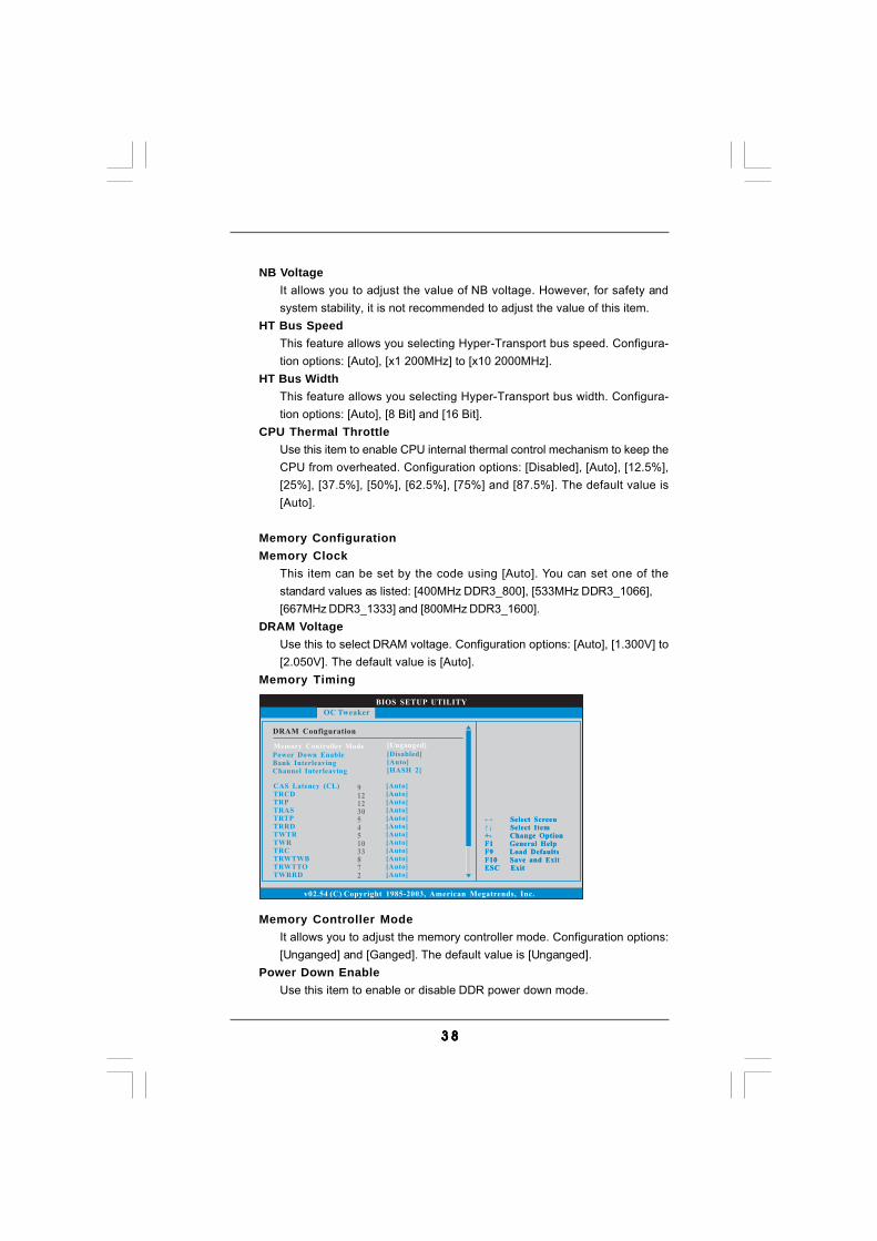
Memory Timing
BIOS SETUP UTILITY
DRAM Configuration
Select ScreenSelect Item
+- Change OptionF1 General HelpF9 Load DefaultsF10 Save and ExitESC Exit
v02.54 (C) Copyright 1985-2003, American Megatrends, Inc.
OC Tweaker
Select ScreenSelect Item
+- Change OptionF1 General HelpF9 Load DefaultsF10 Save and ExitESC Exit
Power Down EnableBank InterleavingChannel Interleaving
[Disabled][Auto][HASH 2]
Memory Controller Mode [Unganged]
91212305451033872
CAS Latency (CL)TRCDTRPTRASTRTPTRRDTWTRTWRTRCTRWTWBTRWTTOTWRRD
[Auto][Auto][Auto][Auto][Auto][Auto][Auto][Auto][Auto][Auto][Auto][Auto]
Memory Controller ModeIt allows you to adjust the memory controller mode. Configuration options:[Unganged] and [Ganged]. The default value is [Unganged].
Power Down EnableUse this item to enable or disable DDR power down mode.

3 93 93 93 93 9
Bank InterleavingInterleaving allows memory accesses to be spread out over banks on thesame node, or accross nodes, decreasing access contention.
Channel InterleavingIt allows you to enable Channel Memory Interleaving. Configuration options:[Disabled], [Address bits 6], [Address bits 12], [Address bits 6], [HASH 1]and [HASH 2]. The default value is [HASH 2].
CAS Latency (CL)Use this item to adjust the means of memory accessing. Configurationoptions: [Auto], [4CLK] to [12CLK]. The default value is [Auto].
TRCDUse this to adjust TRCD values. Configuration options: [Auto], [5CLK] to[12CLK]. The default value is [Auto].
TRPUse this to adjust TRP values. Configuration options: [Auto], [5CLK] to[12CLK]. The default value is [Auto].
TRASUse this to adjust TRAS values. Configuration options: [Auto], [15CLK] to[30CLK]. The default value is [Auto].
TRTPUse this to adjust TRTP values. Configuration options: [Auto], [4CLK] to[7CLK]. The default value is [Auto].
TRRDUse this to adjust TRRD values. Configuration options: [Auto], [4CLK] to[7CLK]. The default value is [Auto].
TWTRUse this to adjust TWTR values. Configuration options: [Auto], [4CLK] to[7CLK]. The default value is [Auto].
TWRUse this to adjust TWR values. Configuration options: [Auto], [5CLK] to[12CLK]. The default value is [Auto].
TRCUse this to adjust TRC values. Configuration options: [Auto], [11CLK] to[42CLK]. The default value is [Auto].
TRWTWBUse this to adjust TRWTWB values. Configuration options: [Auto], [3CLK] to[18CLK]. The default value is [Auto].
TRWTTOUse this to adjust TRWTTD values. Configuration options: [Auto], [3CLK] to[17CLK]. The default value is [Auto].
4 04 04 04 04 0
TWRRDUse this to adjust TWRRD values. Configuration options: [Auto], [2CLK] to[10CLK]. The default value is [Auto].
TWRWRUse this to adjust TWRWR values. Configuration options: [Auto], [2CLK] to[10CLK]. The default value is [Auto].
TRDRDUse this to adjust TRWTTD values. Configuration options: [Auto], [3CLK] to[10CLK]. The default value is [Auto].
TRFC0Use this to adjust TRFC0 values. Configuration options: [Auto], [90ns],[110ns], [160ns], [300ns] and [350ns]. The default value is [Auto].
TRFC1Use this to adjust TRFC1 values. Configuration options: [Auto], [90ns],[110ns], [160ns], [300ns] and [350ns]. The default value is [Auto].
MA TimingUse this to adjust values for MA timing. Configuration options: [Auto], [2T],[1T]. The default value is [Auto].
CHA ADDR/CMD DelayUse this to adjust values for CHA ADDR/CMD Delay feature. Configurationoptions: [Auto], [No Delay], [1/64CLK] to [31/64CLK]. The default value is[Auto].
CHA ADDR/CMD SetupUse this to adjust values for CHA ADDR/CMD Setup feature. Configurationoptions: [Auto], [1/2CLK] and [1CLK]. The default value is [Auto].
CHA CS/ODT DelayUse this to adjust values for CHA CS/ODT Delay feature. Configurationoptions: [Auto], [No Delay], [1/64CLK] to [31/64CLK]. The default value is[Auto].
CHA CS/ODT SetupUse this to adjust values for CHA CS/ODT Setup feature. Configurationoptions: [Auto], [1/2CLK] and [1CLK]. The default value is [Auto].
CHB ADDR/CMD DelayUse this to adjust values for CHB ADDR/CMD Delay feature. Configurationoptions: [Auto], [No Delay], [1/64CLK] to [31/64CLK]. The default value is[Auto].
CHB ADDR/CMD SetupUse this to adjust values for CHB ADDR/CMD Setup feature. Configurationoptions: [Auto], [1/2CLK] and [1CLK]. The default value is [Auto].
4 14 14 14 14 1
CHB CS/ODT DelayUse this to adjust values for CHB CS/ODT Delay feature. Configurationoptions: [Auto], [No Delay], [1/64CLK] to [31/64CLK]. The default value is[Auto].
CHB CS/ODT SetupUse this to adjust values for CHB CS/ODT Setup feature. Configurationoptions: [Auto], [1/2CLK] and [1CLK]. The default value is [Auto].
CHA CKE DriveUse this to adjust values for CHA CKE Drive. Configuration options: [Auto],[1.00x], [1.25x], [1.50x] and [2.00x]. The default value is [Auto].
CHA CS/ODT DriveUse this to adjust values for CHA CS/ODT Drive. Configuration options:[Auto], [1.00x], [1.25x], [1.50x] and [2.00x]. The default value is [Auto].
CHA ADDR/CMD DriveUse this to adjust values for CHA ADDR/CMD Drive. Configuration options:[Auto], [1.00x], [1.25x], [1.50x] and [2.00x]. The default value is [Auto].
CHA CLK DriveUse this to adjust values for CHA CLK Drive. Configuration options: [Auto],[0.75x], [1.00x], [1.25x] and [1.50x]. The default value is [Auto].
CHA DATA DriveUse this to adjust values for CHA DATA Drive. Configuration options: [Auto],[0.75x], [1.00x], [1.25x] and [1.50x]. The default value is [Auto].
CHA DQS DriveUse this to adjust values for CHA DQS Drive. Configuration options: [Auto],[0.75x], [1.00x], [1.25x] and [1.50x]. The default value is [Auto].
CHA Processor ODTUse this to adjust values for CHA Processor ODT. Configuration options:[Auto], [240 ohms], [120 ohms] and [60 ohms]. The default value is [Auto].
CHB CKE DriveUse this to adjust values for CHB CKE Drive. Configuration options: [Auto],[1.00x], [1.25x], [1.50x] and [2.00x]. The default value is [Auto].
CHB CS/ODT DriveUse this to adjust values for CHB CS/ODT Drive. Configuration options:[Auto], [1.00x], [1.25x], [1.50x] and [2.00x]. The default value is [Auto].
CHB ADDR/CMD DriveUse this to adjust values for CHB ADDR/CMD Drive. Configuration options:[Auto], [1.00x], [1.25x], [1.50x] and [2.00x]. The default value is [Auto].
CHB CLK DriveUse this to adjust values for CHB CLK Drive. Configuration options: [Auto],[0.75x], [1.00x], [1.25x] and [1.50x]. The default value is [Auto].
4 24 24 24 24 2
CHB DATA DriveUse this to adjust values for CHB DATA Drive. Configuration options: [Auto],[0.75x], [1.00x], [1.25x] and [1.50x]. The default value is [Auto].
CHB DQS DriveUse this to adjust values for CHB DQS Drive. Configuration options: [Auto],[0.75x], [1.00x], [1.25x] and [1.50x]. The default value is [Auto].
CHB Processor ODTUse this to adjust values for CHB Processor ODT. Configuration options:[Auto], [240 ohms], [120 ohms] and [60 ohms]. The default value is [Auto].
Would you like to save current setting user defaults?In this option, you are allowed to load and save three user defaultsaccording to your own requirements.
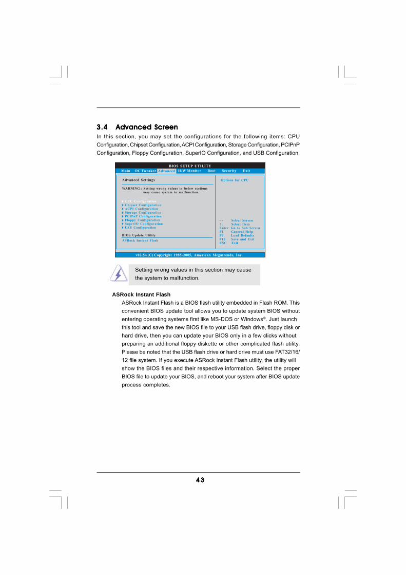
4 34 34 34 34 3
3.43.43.43.43.4 Advanced ScreenAdvanced ScreenAdvanced ScreenAdvanced ScreenAdvanced ScreenIn this section, you may set the configurations for the following items: CPUConfiguration, Chipset Configuration, ACPI Configuration, Storage Configuration, PCIPnPConfiguration, Floppy Configuration, SuperIO Configuration, and USB Configuration.
Setting wrong values in this section may causethe system to malfunction.
BIOS SETUP UTILITY
Main OC Tweaker H/W Monitor Boot Security Exit
Select ScreenSelect Item
Enter Go to Sub ScreenF1 General HelpF9 Load DefaultsF10 Save and ExitESC Exit
v02.54 (C) Copyright 1985-2005, American Megatrends, Inc.
Advanced
Advanced Settings
WARNING : Setting wrong values in below sectionsmay cause system to malfunction.
CPU Configuration
ACPI ConfigurationChipset Configuration
Storage ConfigurationPCIPnP ConfigurationFloppy ConfigurationSuperIO ConfigurationUSB Configuration
Options for CPU
BIOS Update Utility
ASRock Instant Flash
ASRock Instant FlashASRock Instant Flash is a BIOS flash utility embedded in Flash ROM. Thisconvenient BIOS update tool allows you to update system BIOS withoutentering operating systems first like MS-DOS or Windows®. Just launchthis tool and save the new BIOS file to your USB flash drive, floppy disk orhard drive, then you can update your BIOS only in a few clicks withoutpreparing an additional floppy diskette or other complicated flash utility.Please be noted that the USB flash drive or hard drive must use FAT32/16/12 file system. If you execute ASRock Instant Flash utility, the utility willshow the BIOS files and their respective information. Select the properBIOS file to update your BIOS, and reboot your system after BIOS updateprocess completes.
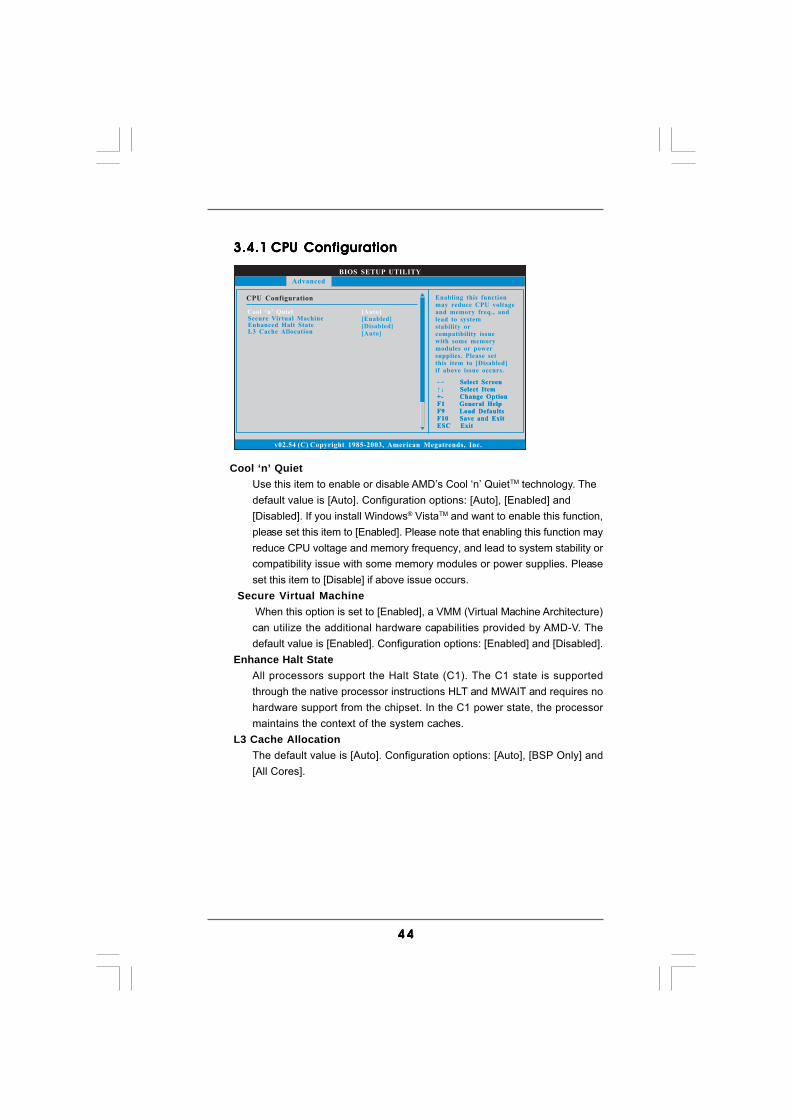
4 44 44 44 44 4
Cool ‘n’ QuietUse this item to enable or disable AMD’s Cool ‘n’ QuietTM technology. Thedefault value is [Auto]. Configuration options: [Auto], [Enabled] and[Disabled]. If you install Windows® VistaTM and want to enable this function,please set this item to [Enabled]. Please note that enabling this function mayreduce CPU voltage and memory frequency, and lead to system stability orcompatibility issue with some memory modules or power supplies. Pleaseset this item to [Disable] if above issue occurs.
Secure Virtual Machine When this option is set to [Enabled], a VMM (Virtual Machine Architecture)can utilize the additional hardware capabilities provided by AMD-V. Thedefault value is [Enabled]. Configuration options: [Enabled] and [Disabled].
Enhance Halt StateAll processors support the Halt State (C1). The C1 state is supportedthrough the native processor instructions HLT and MWAIT and requires nohardware support from the chipset. In the C1 power state, the processormaintains the context of the system caches.
L3 Cache AllocationThe default value is [Auto]. Configuration options: [Auto], [BSP Only] and[All Cores].
3.4.13.4.13.4.13.4.13.4.1 CPU ConfigurationCPU ConfigurationCPU ConfigurationCPU ConfigurationCPU Configuration
BIOS SETUP UTILITY
CPU Configuration
Select ScreenSelect Item
+- Change OptionF1 General HelpF9 Load DefaultsF10 Save and ExitESC Exit
v02.54 (C) Copyright 1985-2003, American Megatrends, Inc.
Advanced
Select ScreenSelect Item
+- Change OptionF1 General HelpF9 Load DefaultsF10 Save and ExitESC Exit
Cool ‘n’ Quiet [Auto]Secure Virtual MachineEnhanced Halt StateL3 Cache Allocation
[Enabled][Disabled][Auto]
Enabling this functionmay reduce CPU voltageand memory freq., andlead to systemstability orcompatibility issuewith some memorymodules or powersupplies. Please setthis item to [Disabled]if above issue occurs.
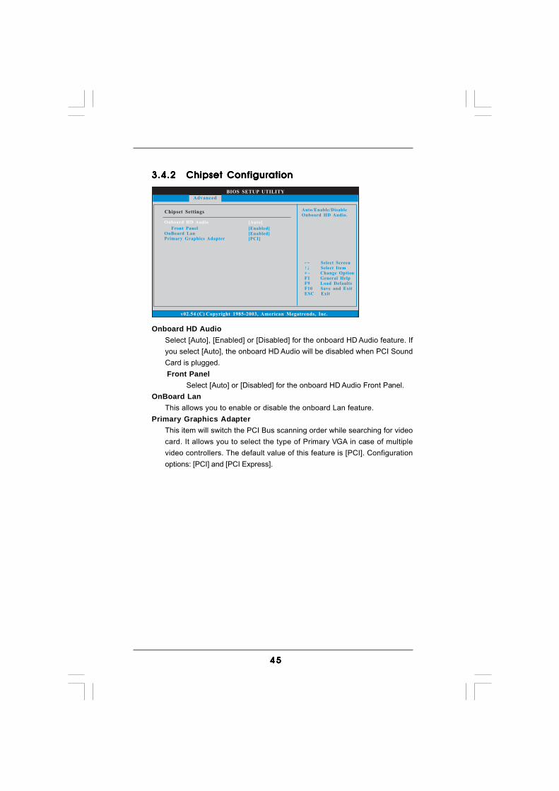
4 54 54 54 54 5
BIOS SETUP UTILITY
v02.54 (C) Copyright 1985-2003, American Megatrends, Inc.
Chipset Settings
Front PanelOnBoard Lan
Graphics AdapterPrimary [PCI]
[Enabled][Enabled]
Select ScreenSelect Item
+ - Change OptionF1 General Help
F10 Save and ExitESC Exit
F9 Load Defaults
Advanced
Auto/Enable/DisableOnboard HD Audio.
Onboard HD Audio [Auto]
3.4.23.4.23.4.23.4.23.4.2 Chipset ConfigurationChipset ConfigurationChipset ConfigurationChipset ConfigurationChipset Configuration
Onboard HD AudioSelect [Auto], [Enabled] or [Disabled] for the onboard HD Audio feature. Ifyou select [Auto], the onboard HD Audio will be disabled when PCI SoundCard is plugged.
Front PanelSelect [Auto] or [Disabled] for the onboard HD Audio Front Panel.
OnBoard LanThis allows you to enable or disable the onboard Lan feature.
Primary Graphics AdapterThis item will switch the PCI Bus scanning order while searching for videocard. It allows you to select the type of Primary VGA in case of multiplevideo controllers. The default value of this feature is [PCI]. Configurationoptions: [PCI] and [PCI Express].
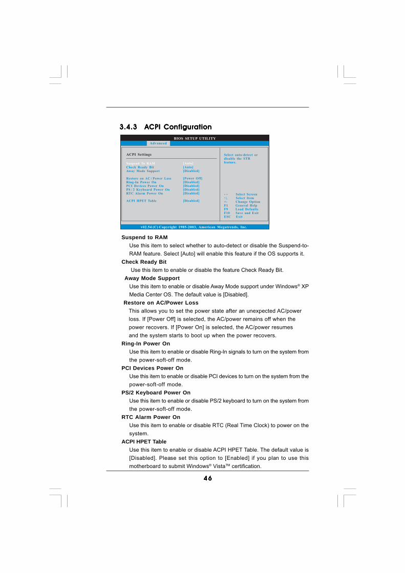
4 64 64 64 64 6
BIOS SETUP UTILITY
ACPI Settings Select auto-detect ordisable the STRfeature.
Select ScreenSelect Item
+- Change OptionF1 General HelpF9 Load DefaultsF10 Save and ExitESC Exit
v02.54 (C) Copyright 1985-2003, American Megatrends, Inc.
Advanced
Suspend To RAM
Check Ready BitAway Mode Support
Restore on AC / Power LossRing-In Power OnPCI Devices Power OnPS / 2 Keyboard Power OnRTC Alarm Power On
ACPI HPET Table
[Auto]
[Auto][Disabled]
[Power Off][Disabled][Disabled][Disabled][Disabled]
[Disabled]
3.4.33.4.33.4.33.4.33.4.3 ACPI ConfigurationACPI ConfigurationACPI ConfigurationACPI ConfigurationACPI Configuration
Suspend to RAMUse this item to select whether to auto-detect or disable the Suspend-to-RAM feature. Select [Auto] will enable this feature if the OS supports it.
Check Ready Bit Use this item to enable or disable the feature Check Ready Bit.
Away Mode SupportUse this item to enable or disable Away Mode support under Windows® XPMedia Center OS. The default value is [Disabled].
Restore on AC/Power Loss This allows you to set the power state after an unexpected AC/power loss. If [Power Off] is selected, the AC/power remains off when the power recovers. If [Power On] is selected, the AC/power resumes and the system starts to boot up when the power recovers.
Ring-In Power OnUse this item to enable or disable Ring-In signals to turn on the system fromthe power-soft-off mode.
PCI Devices Power OnUse this item to enable or disable PCI devices to turn on the system from thepower-soft-off mode.
PS/2 Keyboard Power OnUse this item to enable or disable PS/2 keyboard to turn on the system fromthe power-soft-off mode.
RTC Alarm Power OnUse this item to enable or disable RTC (Real Time Clock) to power on thesystem.
ACPI HPET TableUse this item to enable or disable ACPI HPET Table. The default value is[Disabled]. Please set this option to [Enabled] if you plan to use thismotherboard to submit Windows® VistaTM certification.
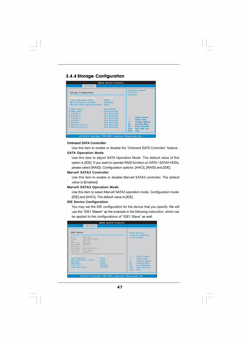
4 74 74 74 74 7
BIOS SETUP UTILITY
Storage Configuration
v02.54 (C) Copyright 1985-2003, American Megatrends, Inc.
Advanced
Onboard SATA Controller
SATA Operation ModeMarvell SATA3 ControllerMarvell SATA3 Operation Mode
IDE1 MasterIDE1 SlaveSATAII_1SATAII_2SATAII_3SATAII_4ESATA1Marvell SATA3_1Marvell SATA3_2
[Enabled]
[IDE][Enabled][IDE]
[Hard Disk][Not Detected][Not Detected][Not Detected][Not Detected][Not Detected][Not Detected][Not Detected][Not Detected]
Select ScreenSelect Item
+- Change OptionF1 General HelpF9 Load DefaultsF10 Save and ExitESC Exit
Select ScreenSelect Item
+- Change OptionF1 General HelpF9 Load DefaultsF10 Save and ExitESC Exit
Configure onboardserial ATAcontroller.
3.4.43.4.43.4.43.4.43.4.4 Storage ConfigurationStorage ConfigurationStorage ConfigurationStorage ConfigurationStorage Configuration
Onboard SATA ControllerUse this item to enable or disable the “Onboard SATA Controller” feature.
SATA Operation ModeUse this item to adjust SATA Operation Mode. The default value of thisoption is [IDE]. If you want to operate RAID function on SATA / SATAII HDDs,please select [RAID]. Configuration options: [AHCI], [RAID] and [IDE].
Marvell SATA3 ControllerUse this item to enable or disable Marvell SATA3 controller. The defaultvalue is [Enabled].
Marvell SATA3 Operation ModeUse this item to select Marvell SATA3 operation mode. Configuration mode:[IDE] and [AHCI]. The default value is [IDE].
IDE Device ConfigurationYou may set the IDE configuration for the device that you specify. We willuse the “IDE1 Master” as the example in the following instruction, which canbe applied to the configurations of “IDE1 Slave” as well.
BIOS SETUP UTILITY
IDE Master Select the typeof device connectedto the system.
Select ScreenSelect Item
+- Change OptionF1 General HelpF9 Load DefaultsF10 Save and ExitESC Exit
v02.54 (C) Copyright 1985-2003, American Megatrends, Inc.
Advanced
Type
LBA/Large ModeBlock (Multi-Sector Transfer)PIO ModeDMA ModeS . M . A . R . T .32Bit Data Transfer
[Auto]
[Auto][Auto][Auto][Auto][Disabled][Disabled]
DeviceVendorSizeLBA ModeBlock ModePIO ModeAsync DMAUltra DMAS.M.A.R.T.
:Hard Disk:MAXTOR 6L080J4:80.0 GB:Supported:16Sectors:4:MultiWord DMA-2:Ultra DMA-6:Supported
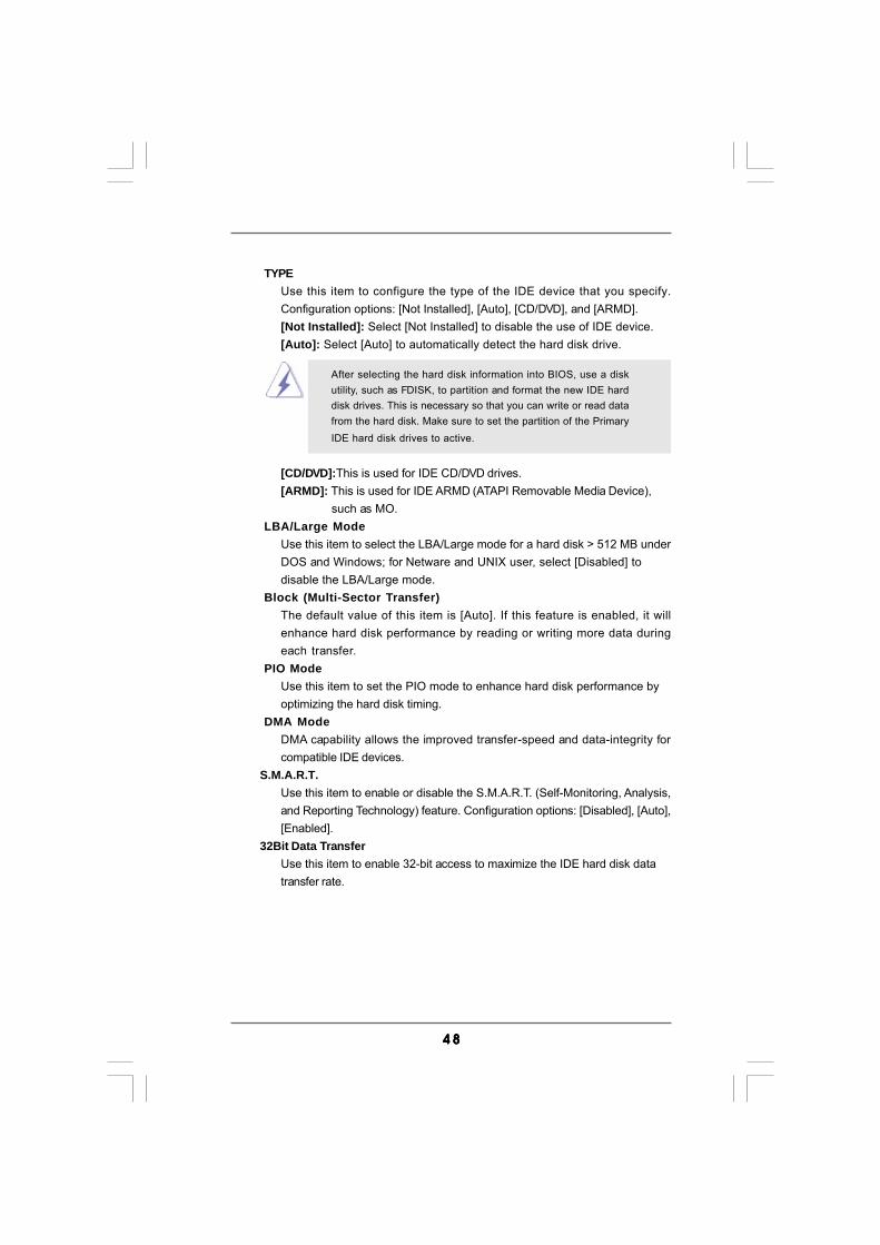
4 84 84 84 84 8
TYPEUse this item to configure the type of the IDE device that you specify.Configuration options: [Not Installed], [Auto], [CD/DVD], and [ARMD].[Not Installed]: Select [Not Installed] to disable the use of IDE device.[Auto]: Select [Auto] to automatically detect the hard disk drive.
After selecting the hard disk information into BIOS, use a diskutility, such as FDISK, to partition and format the new IDE harddisk drives. This is necessary so that you can write or read datafrom the hard disk. Make sure to set the partition of the PrimaryIDE hard disk drives to active.
[CD/DVD]:This is used for IDE CD/DVD drives.[ARMD]: This is used for IDE ARMD (ATAPI Removable Media Device),
such as MO.LBA/Large Mode
Use this item to select the LBA/Large mode for a hard disk > 512 MB underDOS and Windows; for Netware and UNIX user, select [Disabled] todisable the LBA/Large mode.
Block (Multi-Sector Transfer)The default value of this item is [Auto]. If this feature is enabled, it willenhance hard disk performance by reading or writing more data duringeach transfer.
PIO ModeUse this item to set the PIO mode to enhance hard disk performance byoptimizing the hard disk timing.
DMA ModeDMA capability allows the improved transfer-speed and data-integrity forcompatible IDE devices.
S.M.A.R.T.Use this item to enable or disable the S.M.A.R.T. (Self-Monitoring, Analysis,and Reporting Technology) feature. Configuration options: [Disabled], [Auto],[Enabled].
32Bit Data TransferUse this item to enable 32-bit access to maximize the IDE hard disk datatransfer rate.
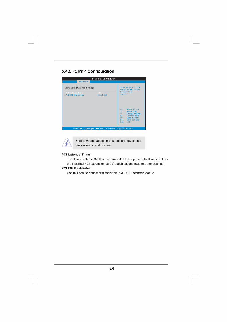
4 94 94 94 94 9
BIOS SETUP UTILITY
Advanced PCI / PnP Settings Value in units of PCIclocks for PCI devicelatency timerregister.
Select ScreenSelect Item
+- Change OptionF1 General HelpF9 Load DefaultsF10 Save and ExitESC Exit
v02.54 (C) Copyright 1985-2003, American Megatrends, Inc.
PCI Latency TimerPCI IDE BusMaster
[32][Enabled]
Advanced
3.4.53.4.53.4.53.4.53.4.5 PCIPnP ConfigurationPCIPnP ConfigurationPCIPnP ConfigurationPCIPnP ConfigurationPCIPnP Configuration
Setting wrong values in this section may causethe system to malfunction.
PCI Latency TimerThe default value is 32. It is recommended to keep the default value unlessthe installed PCI expansion cards’ specifications require other settings.
PCI IDE BusMasterUse this item to enable or disable the PCI IDE BusMaster feature.
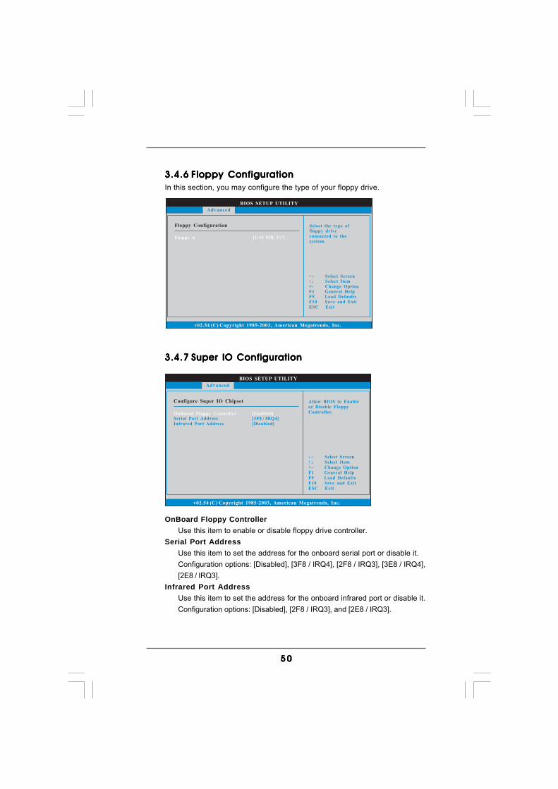
5 05 05 05 05 0
BIOS SETUP UTILITY
Floppy Configuration Select the type offloppy driveconnected to thesystem.
Select ScreenSelect Item
+- Change OptionF1 General HelpF9 Load DefaultsF10 Save and ExitESC Exit
v02.54 (C) Copyright 1985-2003, American Megatrends, Inc.
Advanced
Floppy A [1.44 MB 3 "]12
BIOS SETUP UTILITY
Configure Super IO Chipset Allow BIOS to Enableor Disable FloppyController.
Select ScreenSelect Item
+- Change OptionF1 General HelpF9 Load DefaultsF10 Save and ExitESC Exit
v02.54 (C) Copyright 1985-2003, American Megatrends, Inc.
Advanced
OnBoard Floppy ControllerSerial Port AddressInfrared Port Address
[Enabled][3F8 / IRQ4][Disabled]
3.4.63.4.63.4.63.4.63.4.6 Floppy ConfigurationFloppy ConfigurationFloppy ConfigurationFloppy ConfigurationFloppy ConfigurationIn this section, you may configure the type of your floppy drive.
3.4.73.4.73.4.73.4.73.4.7 Super IO ConfigurationSuper IO ConfigurationSuper IO ConfigurationSuper IO ConfigurationSuper IO Configuration
OnBoard Floppy ControllerUse this item to enable or disable floppy drive controller.
Serial Port AddressUse this item to set the address for the onboard serial port or disable it.Configuration options: [Disabled], [3F8 / IRQ4], [2F8 / IRQ3], [3E8 / IRQ4],[2E8 / IRQ3].
Infrared Port AddressUse this item to set the address for the onboard infrared port or disable it.Configuration options: [Disabled], [2F8 / IRQ3], and [2E8 / IRQ3].
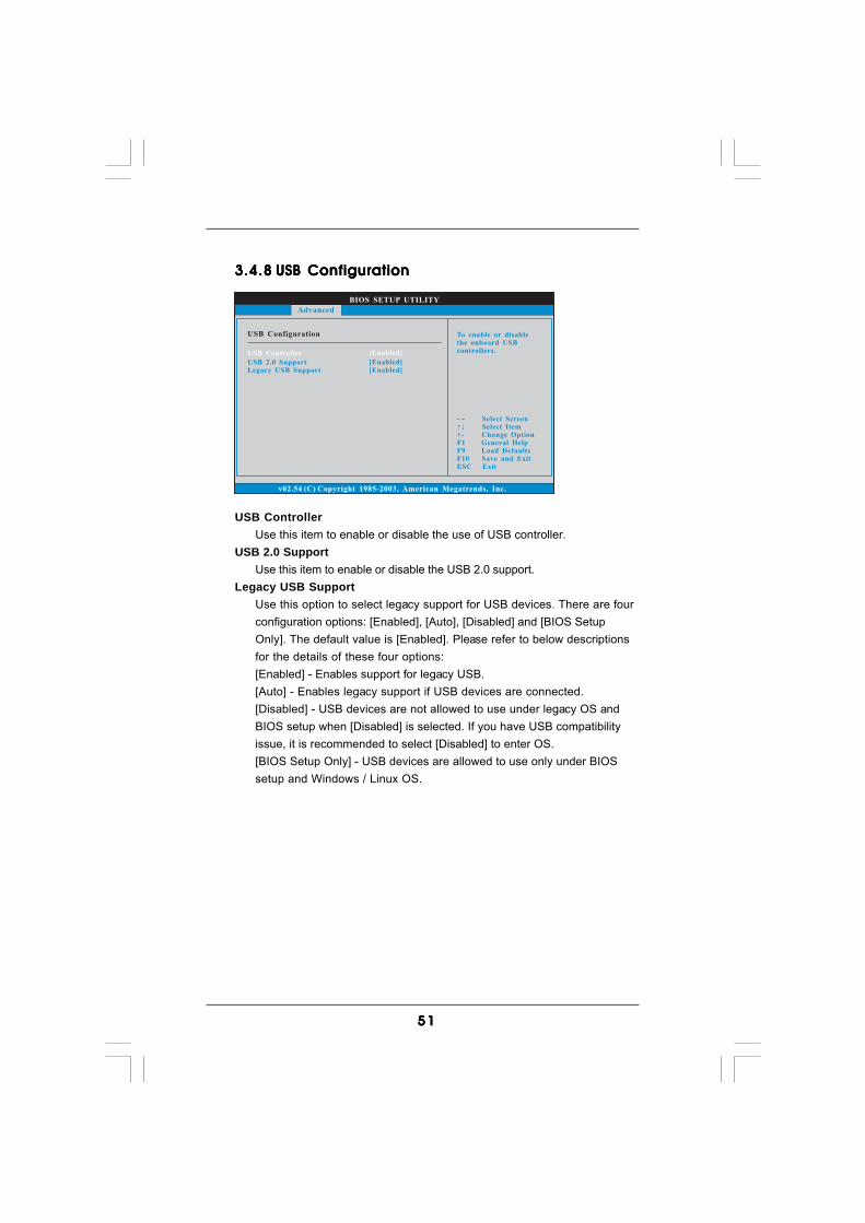
5 15 15 15 15 1
BIOS SETUP UTILITY
USB Configuration To enable or disablethe onboard USBcontrollers.
Select ScreenSelect Item
+- Change OptionF1 General HelpF9 Load DefaultsF10 Save and ExitESC Exit
v02.54 (C) Copyright 1985-2003, American Megatrends, Inc.
Advanced
USB Controller
USB 2.0 SupportLegacy USB Support
[Enabled]
[Enabled][Enabled]
3.4.83.4.83.4.83.4.83.4.8 USB ConfigurationUSB ConfigurationUSB ConfigurationUSB ConfigurationUSB Configuration
USB ControllerUse this item to enable or disable the use of USB controller.
USB 2.0 SupportUse this item to enable or disable the USB 2.0 support.
Legacy USB SupportUse this option to select legacy support for USB devices. There are fourconfiguration options: [Enabled], [Auto], [Disabled] and [BIOS SetupOnly]. The default value is [Enabled]. Please refer to below descriptionsfor the details of these four options:[Enabled] - Enables support for legacy USB.[Auto] - Enables legacy support if USB devices are connected.[Disabled] - USB devices are not allowed to use under legacy OS andBIOS setup when [Disabled] is selected. If you have USB compatibilityissue, it is recommended to select [Disabled] to enter OS.[BIOS Setup Only] - USB devices are allowed to use only under BIOSsetup and Windows / Linux OS.
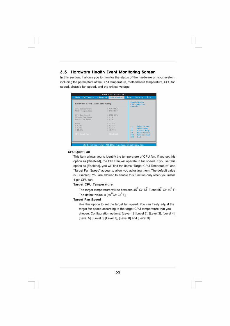
5 25 25 25 25 2
BIOS SETUP UTILITY
Hardware Health Event Monitoring
Select ScreenSelect Item
F1 General HelpF9 Load DefaultsF10 Save and ExitESC Exit
v02.54 (C) Copyright 1985-2003, American Megatrends, Inc.
CPU TemperatureM / B Temperature
CPU Fan SpeedChassis Fan Speed
Vcore+ 3.30V+ 5.00V+ 12.00V
Power Fan Speed
: 37 C / 98 F
: 4722 RPM
: 1.216V: 3.248V: 5.136V: 12.091V
: 27 C / 80 F
: N / A: N / A
Main OC Tweaker Advanced Boot Security ExitH/W Monitor
Enable/DisableCPU Quiet FanFunction.
CPU Quiet Fan [Disabled]
3.53 .53 .53 .53 .5 Hardware Health Event Monitoring ScreenHardware Health Event Monitoring ScreenHardware Health Event Monitoring ScreenHardware Health Event Monitoring ScreenHardware Health Event Monitoring ScreenIn this section, it allows you to monitor the status of the hardware on your system,including the parameters of the CPU temperature, motherboard temperature, CPU fanspeed, chassis fan speed, and the critical voltage.
CPU Quiet FanThis item allows you to identify the temperature of CPU fan. If you set thisoption as [Disabled], the CPU fan will operate in full speed. If you set thisoption as [Enabled], you will find the items “Target CPU Temperature” and“Target Fan Speed” appear to allow you adjusting them. The default valueis [Disabled]. You are allowed to enable this function only when you install4-pin CPU fan.Target CPU Temperature
The target temperature will be between 45 C/113 F and 65 C/149 F.The default value is [50 C/122 F].
Target Fan SpeedUse this option to set the target fan speed. You can freely adjust thetarget fan speed according to the target CPU temperature that youchoose. Configuration options: [Level 1], [Level 2], [Level 3], [Level 4],[Level 5], [Level 6] [Level 7], [Level 8] and [Level 9].
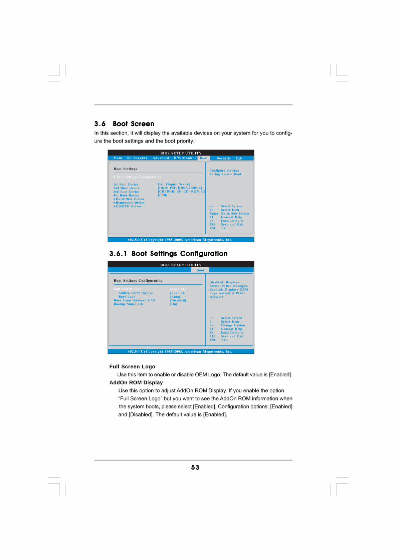
5 35 35 35 35 3
BIOS SETUP UTILITY
Main OC Tweaker Advanced H/W Monitor Security Exit
Boot SettingsConfigure Settingsduring System Boot.
Select ScreenSelect Item
Enter Go to Sub ScreenF1 General HelpF9 Load DefaultsF10 Save and ExitESC Exit
v02.54 (C) Copyright 1985-2005, American Megatrends, Inc.
Boot
Boot Settings Configuration
1st Boot Device2nd Boot Device3rd Boot Device4th Boot Device
Hard Disk DrivesRemovable DrivesCD/DVD Drives
[1st Floppy Device][HDD: PM - HDS722580VL][CD / DVD: 3S - CD - ROM C][USB]
BIOS SETUP UTILITY
Boot Settings ConfigurationDisabled: Displaysnormal POST messages.Enabled: Displays OEMLogo instead of POSTmessages.
Select ScreenSelect Item
+ - Change OptionF1 General HelpF9 Load DefaultsF10 Save and ExitESC Exit
v02.54 (C) Copyright 1985-2003, American Megatrends, Inc.
Boot
AddOn ROM DisplayBoot Logo
Boot From Onboard LANBootup Num-Lock
[Enabled][Auto][Disabled][On]
Full Screen Logo [Enabled]
3.63 .63 .63 .63 .6 Boot ScreenBoot ScreenBoot ScreenBoot ScreenBoot ScreenIn this section, it will display the available devices on your system for you to config-ure the boot settings and the boot priority.
3.6.13.6.13.6.13.6.13.6.1 Boot Settings ConfigurationBoot Settings ConfigurationBoot Settings ConfigurationBoot Settings ConfigurationBoot Settings Configuration
Full Screen Logo Use this item to enable or disable OEM Logo. The default value is [Enabled].AddOn ROM Display Use this option to adjust AddOn ROM Display. If you enable the option “Full Screen Logo” but you want to see the AddOn ROM information when the system boots, please select [Enabled]. Configuration options: [Enabled] and [Disabled]. The default value is [Enabled].
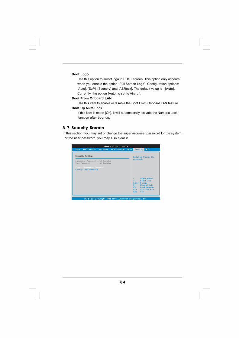
5 45 45 45 45 4
BIOS SETUP UTILITY
Main OC Tweaker Advanced H/W Monitor Boot Exit
Install or Change thepassword.
Select ScreenSelect Item
Enter ChangeF1 General Help
F10 Save and ExitESC Exit
F9 Load Defaults
v02.54 (C) Copyright 1985-2005, American Megatrends, Inc.
Security
Change Supervisor Password
Change User Password
Security Settings
Supervisor Password : Not InstalledUser Password : Not Installed
Boot LogoUse this option to select logo in POST screen. This option only appearswhen you enable the option “Full Screen Logo”. Configuration options:[Auto], [EuP], [Scenery] and [ASRock]. The default value is [Auto].Currently, the option [Auto] is set to Aircraft.
Boot From Onboard LANUse this item to enable or disable the Boot From Onboard LAN feature.
Boot Up Num-LockIf this item is set to [On], it will automatically activate the Numeric Lockfunction after boot-up.
3.73 .73 .73 .73 .7 Security ScreenSecurity ScreenSecurity ScreenSecurity ScreenSecurity ScreenIn this section, you may set or change the supervisor/user password for the system.For the user password, you may also clear it.
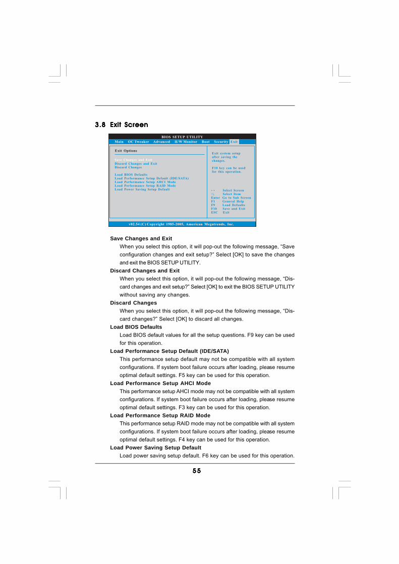
5 55 55 55 55 5
BIOS SETUP UTILITY
Main OC Tweaker Advanced H/W Monitor Boot Security
Exit system setupafter saving thechanges.
F10 key can be usedfor this operation.
Select ScreenSelect Item
Enter Go to Sub ScreenF1 General Help
F10 Save and ExitESC Exit
F9 Load Defaults
v02.54 (C) Copyright 1985-2005, American Megatrends, Inc.
Exit
Save Changes and Exit
Discard Changes and ExitDiscard Changes
Load BIOS DefaultsLoad Performance Setup Default (IDE/SATA)Load Performance Setup AHCI ModeLoad Performance Setup RAID ModeLoad Power Saving Setup Default
Exit Options
3.83.83.83.83.8 Exit ScreenExit ScreenExit ScreenExit ScreenExit Screen
Save Changes and ExitWhen you select this option, it will pop-out the following message, “Saveconfiguration changes and exit setup?” Select [OK] to save the changesand exit the BIOS SETUP UTILITY.
Discard Changes and ExitWhen you select this option, it will pop-out the following message, “Dis-card changes and exit setup?” Select [OK] to exit the BIOS SETUP UTILITYwithout saving any changes.
Discard ChangesWhen you select this option, it will pop-out the following message, “Dis-card changes?” Select [OK] to discard all changes.
Load BIOS DefaultsLoad BIOS default values for all the setup questions. F9 key can be usedfor this operation.
Load Performance Setup Default (IDE/SATA)This performance setup default may not be compatible with all systemconfigurations. If system boot failure occurs after loading, please resumeoptimal default settings. F5 key can be used for this operation.
Load Performance Setup AHCI ModeThis performance setup AHCI mode may not be compatible with all systemconfigurations. If system boot failure occurs after loading, please resumeoptimal default settings. F3 key can be used for this operation.
Load Performance Setup RAID ModeThis performance setup RAID mode may not be compatible with all systemconfigurations. If system boot failure occurs after loading, please resumeoptimal default settings. F4 key can be used for this operation.
Load Power Saving Setup DefaultLoad power saving setup default. F6 key can be used for this operation.
5 65 65 65 65 6
4.4.4.4.4. SofSofSofSofSoftware Supportware Supportware Supportware Supportware Supporttttt4.1 Install Operating System4.1 Install Operating System4.1 Install Operating System4.1 Install Operating System4.1 Install Operating SystemThis motherboard supports various Microsoft® Windows® operating systems: 7 / 764-bit / VistaTM / VistaTM 64-bit / XP / XP Media Center / XP 64-bit. Because motherboardsettings and hardware options vary, use the setup procedures in this chapter forgeneral reference only. Refer to your OS documentation for more information.
4.2 Support CD Information4.2 Support CD Information4.2 Support CD Information4.2 Support CD Information4.2 Support CD InformationThe Support CD that came with the motherboard contains necessary drivers anduseful utilities that enhance the motherboard features.
4.2.1 Running The Support CD4.2.1 Running The Support CD4.2.1 Running The Support CD4.2.1 Running The Support CD4.2.1 Running The Support CDTo begin using the support CD, insert the CD into your CD-ROM drive. The CDautomatically displays the Main Menu if “AUTORUN” is enabled in your computer.If the Main Menu did not appear automatically, locate and double click on the file“ASSETUP.EXE” from the BIN folder in the Support CD to display the menus.
4.2.2 Drivers Menu4.2.2 Drivers Menu4.2.2 Drivers Menu4.2.2 Drivers Menu4.2.2 Drivers MenuThe Drivers Menu shows the available devices drivers if the system detects theinstalled devices. Please install the necessary drivers to activate the devices.
4.2.3 Utilities Menu4.2.3 Utilities Menu4.2.3 Utilities Menu4.2.3 Utilities Menu4.2.3 Utilities MenuThe Utilities Menu shows the applications software that the motherboard supports.Click on a specific item then follow the installation wizard to install it.
4.2.44.2.44.2.44.2.44.2.4 Contact InformationContact InformationContact InformationContact InformationContact InformationIf you need to contact ASRock or want to know more about ASRock, welcometo visit ASRock’s website at http://www.asrock.com; or you may contact yourdealer for further information.