manual, 2300 automatic standby controller - nordson emanuals!
TRANSCRIPT

Automatic Standby Controller
Part107980A
NORDSON CORPORATION. AMHERST, OHIO. USA

Nordson Corporation welcomes requests for information, comments and inquiries about its products.
Address all correspondence to
Nordson Corporation 11475 Lakefield Drive
Duluth, GA 30136
This is a Nordson Corporation publication which is protected by copyright. No part of this document may be photocopied, reproduced, or translated to another language without the prior written consent of Nordson
Corporation. The information contained in this publication is subject to change without notice.
Trademarks
AquaGuard, Blue Box, Control Coat, Equi=Bead, FloMelt, FoamMelt, FoamMix, Helix, Hot Shot, Hot Stitch, Meltex, MicroSet, MultiScan, Nordson, the Nordson logo, OmniScan, Porous Coat, Posi-Stop, RBX, Sure-Bond,
UniScan, UpTime, and Versa-Spray are registered trademarks of Nordson Corporation.
BetterBooksM, CF. Controlled Fiberization, Easy-Screen, Fibermelt, Flo-Tracker, Values are trademarks of Nordson Corporation.
PrintGuard, and Package of
Manual 46-83 107 980A 0 1991 Nordson Corporation Issued 9/9 1 All Rights Reserved

Automatic Standby Controller Manual 46-83
Page O-l
Table of Contents
SECTHON 1
SAFETY SUMMARY
INTRODUCTION ................................................................................................................................ l-l EXPLANATION OF TERMS AND SYMBOLS ............................................................................... l-l SAFETY DURING INSTALLATION.. .............................................................................................. l-2
Electrical .................................................................................................................................. l-2 Pneumatic ................................................................................................................................ l-2
SAFETY DURING OPERATION ....................................................................................................... l-2 SAFETY DURING SERVICING ........................................................................................................ l-3 SAFETY WHEN USING HOT MELT ADHESIVES AND SOLVENTS ........................................ l-4
Hot Melt Adhesives.. ............................................................................................................... l-4 Heating Solvents.. ................................................................................................................... 1-5
SECTION 2
EQUIPMENT FAMILIARIZATION
INTRODUCTION.. ............................................................................................................................... 2- 1 GENERAL OPER,ATION ................................................................................................................... .2-2
Standby Condition ................................................................................................................. .2-2 Shutdown Enabled Condition.. ............................................................................................. .2-3 Sleep Enabled Condition.. ..................................................................................................... .2-3 Devices Using the Automatic Standby Controller.. ........................................................... .2-3
USING THE CONTROLLER WITH SERIES 3000 APPLICATORS ........................................... .2-4 Full Power Mode .................................................................................................................... .2-4 Auto Standby Mode ............................................................................................................... .2-5
USING THE CONTROLLER WITH 2300 APPLICATORS ........................................................... .2-6 Full Power Mode .................................................................................................................... .2-7 Auto Standby Mode.. ............................................................................................................. .2-7
USING THE CONTROLLER WITH SERIES 6000 APPLICATORS ........................................... .2-8 Full Power Mode .......................................... .......................................................................... 2-8 Auto Standby Mode ................................................................................................................ 2-8
USING THE CONTROLLER WITH PRE-LCU BULK MELTERS.. ............................................ .2-10 Full Power Mode .......................................... ......................................................................... .2-10 Auto Standby Mode ............................................................................................................... .2- 10
USING THE CONTROLLER WITH SERIES 5000 LCU BULK MELTERS ............................... 2-11 Full Power Mode .................................................................................................................... .2- 11 Auto Standby Mode ..................................... . .......................................................................... .2- 11
USING THE STANDBY CONTROLLER WITH g-CHANNEL TEMPERATURE CONTROLLER.. .............................................................................. .2-13
Full Power Mode .................................................................................................................... .2-13 Auto Standby Mode ............................................................................................................... .2- 13
Pubkatlon No. 107 980A @I NORDSON CORPORATION 1991 All Rights Reserved
Issued 9191

Manual 46-83 Page O-2
Automatic Standby Controller
SECTION 3
INSTALLATION
INTRODUCTION ................................................................................................................................. 3-1 Remote Connections ............................................................................................................... 3-1
INSPECTION ....................................................................................................................................... 3- 1 SERIES 3000 INSTALLATION (with MultiScan@ Control System). .......................................... .3-3
Safety Precautions .................................................................................................................. 3-3
SERIES 2300 INSTALLATION ......................................................................................................... 3-15 . Safety Precautions 3- 15 ................................................................................................................... Preliminary Installation Steps ............................................................................................. 3-16
2300-Specific Installation Procedures.. ............................................................................... .3- 17 Final Installation Steps ......................................................................................................... ‘3-24 .
SERIES 6000 INSTALLATION .......................................................................................................... 3-25
Safety Precautions .................................................................................................................. 3-25
Introduction ................................................................................................ Preliminary Series 6000 Installation Steps.. ......................................... Non-Universal Machine Interface Steps.. ............................................... Universal Machine Interface-specific Steps.. ......................................... Final Series 6000 Installation Steps.. .....................................................
PRE-LCU BULK MELTER INSTALLATION (Models 500, 5505, 5510, 5520
............................ 3-26 .
............................ 3-26
............................ 3-28 t
............................ 3-30
............................ 3-32 c
.......................... 3-33 t
Safety Precautions ................................................................................................................. 3-33
Installation Procedures .......................................................................................................... 3-34
SERIES 5000 LCU BULK MELTER INSTALLATION (Models 505, 506, 5506, 551, 5530, 5540, 5550, 55511) ............................................... 3-38
Safety Precautions ................................................................................................................. .3-38 Installation Procedures .......................................................................................................... 3-39
g-CHANNEL TEMPERATURE CONTROLLER INSTALLATION ............................................... 3-43 Safety Precautions.. ............................................................................................................... .3-43 Preliminary Installation Steps 3-45 ............................................................................................. . Standby Controller Installation.. ......................................................................................... .3-46 Temperature Controller-Specific Installation Procedures ............................................... .3-48 Final Installation Steps ......................................................................................................... 3-53
SECTION 4
OPERATING INSTRUCTIONS
OPERATING MODES ........................................................................................................................ .4- 1 Full Power Mode .................................................................................................................... .4- 1 Auto Standby Mode ................................................................................................................ 4-2
SETTING CONTROLLER CONDITIONS ....................................................................................... .4-4
Issued 9191 0 NORDSON CORPORATION 1991 All Rights Reserved
Publication No. 107 980A

Automatic Standby Controller Manual 46-83 Page O-3
SECTION 5
TROUBLESHOOTING
INTRODUCTION ................................................................................................................................. 5-l SAFETY DURING TROUBLESHOOTING ..................................................................................... 5-1
Mode LEDs Not Lighting ....................................................................................................... 5-2 “Standby On” LED Not Lighting .......................................................................................... 5-4 “Shutdown ON” LED Not Lighting ....................................................................................... 5-5 c
SECTIO:N 6 PARTS LISTS
INTRODUCTION. ...................................................... . ........................................................................ 6-l Using the Illustrated Parts List ...................... . ................................................................... 6-l
SECTIO’N 7 TECHNICAL DATA
AUTOMATIC STANDBY CONTROLLER SPECIFICATIONS ,..................................................... 7-l
Publication No. 107 980A 0 NORDSON CORPORATION 1991 All Rights Reserved
Issued 9/91

Manual 46-83 Page O-4
Automatic Standby Controller
List of Illustrations
Figure 2.1 - Automatic Standby Controller ..................................................................................... 2-l
Figure 3.1 - Automatic Standby Controller (Door Open) ................................................................ 3-2
Figure 3.2 - Controller PCB (rotated 90). ......................................................................................... 3-2
Figure 3.3 - Series 3000 Applicator, Piston Pump Model (with MultiScan Control System) ................................................................................. 3-6
Figure 3.4 - Controller to Series 3000 Piston Pump, Remote I/O Temperature Standby Electrical Connections ........................................ 3-7
Figure 3.5 - Controller to Series 3000, Piston Pump, Remote I/O Sleep Enabled Electrical Connections.. .................................................. .3-9
Figure 3.6 - Series 3000 Applicator, Gear Pump Model, (with MultiScan Control System) ................................................................................. 3-10
Figure 3.7 - Controller to Series 3000, Gear Pump, Remote I/O Temperature Setback Electrical Connections ......................................... 3-11
Figure 3.8 - Controller to Series 3000, Gear Pump, Remote I/O Sleep Enabled Electrical Connections ..................................................... 3-13
Figure 3.9 - Series 2300 Applicator ................................................................................................... 3-19
Figure 3.10 - Controller to Series 2300 Applicator Electrical Connections ................................ .3-2 1
Figure 3.11 - Electrical Connections for Installation of Contactor Between Controller and 2300 Applicator.. .................................................................................. .3-23
Figure 3.12 - Controller to Series 6000 Applicators (without UMI) Electrical Connections .......................................................................... 3-29
Figure 3.13 - Controller to Series 6000 Applicators (with UMI) Electrical Connections .............................................................................. .3-3 1
Figure 3.14 - Location of Bulk Melter Adapter Card, C2 ............................................................... 3-41
Figure 3.15 - g-channel Temperature Controller.. ......................................................................... .3-46
Figure 3.16 - Standby Controller to Temperature Controller Electrical Connections .............. .3-50
Figure 3.17 - Electrical Connections for Installing Contactor Between the Standby Controller and Temperature Controller ....................................................... 3-53
Figure 4.1 - Controller LED Locations .............................................................................................. 4-l
Figure 4.2 - Controller Pot Locations ................................................................................................ 4-5
Figure 5.1 - Controller Printed Circuit Board ................................................................................. 5-6
Figure 5.2 - Controller Electrical Wiring Diagram ......................................................................... 5-8
Figure 5.3 - Controller Electrical Schematic ................................................................................... 5-10
List of Tables
Table 2.1 - Equipment Needed to Use Controller Relay Contacts to Activate Standby and/or Shutdown with 2300 Applicators .I . . . . . . . . . . . . . . . . . . . . . . . . . . . . . . . . . . . . . . . . . . . . . . . . . . . . 2-6
Table 2.2 - Equipment Needed to Use Standby Controller Relay Contacts to Activate Standby and/or Shutdown with g-Channel Temperature Controllers . . . . . . . . . . . . . . . . . . . . . 2-13
Table 6.1 - Automatic Standby Controller Parts List . . . . . . . . . . . . . . . . . . . . . . . . . . . . . . . . . . . . . . . . . . . . . . . . . . . . . . . . . . . . . . . . . . . . . 6-3
Issued 9191 0 NORDSON CORPORATION 1991 All Rights Reserved
Publication No. 107 980A

Automatic Standby Controller Manual 45-83 Page l-l
SECTION 1 SAFETY SUMMARY
INTRODUCTION
This section provides safety guidelines for use of Nordson@ equipment. These guidelines apply to all operations and service personnel working with the application equipment and its components. Safety war:nings are repeated throughout this manual, along with specific warnings and cautions not included in this section. These safety guidelines cover installation, operation and servicing.
A WARNING: Failure to follow these recommendations may result in personal injury from burns or electrocution and/or cause equipment and property damage.
EXPLANATION OF TERMS AND SYMBOLS
The following safety symbols and signal words are used throughout this publication, alerting the reader to personal safety hazards, or identifying conditions that may result in equipment or property damage.
A WARNING: General Warning. Failure to observe may result in personal injury or death.
A WARNING: Risk of electrical shock. Failure to ob-
5 serve may result in personal injury or death.
A CAUTION: General Caution. Failure to observe may result in mirror personal injury or damage to property.
NOTE: Important information. Failure to observe may result in equipment damage.
Publication No. 107 980A G Nordson Corporation 1991 All Rights Reserved
Issued 9’91

Manual 46-83 Page 1-2
Automatic Standby Controller
SAFETY DURING INSTALLATION
Electrical
1. A protective electrical ground connection to a reliable earth ground is essential for safe operation. Without a reliable ground, all accessible conductive components (including knobs and controls that appear insulated) can render an electric shock.
2. A disconnect switch with lockout capability must be provided between the power source and the equipment.
3. The power supply’s wire gauge and insulation must be sufficient to meet application equipment temperature and power require- ments.
4. Only fuses of the correct type, voltage rating and current rating should be used. Refer to the application equipment parts list foi fuse recommendations. Using incorrect or non-recommended fuses can present a fire hazard.
Pneumatic
It is recommended that a three-way, manual valve with lockout capability, be installed in the air supply line to Nordson equip- ment. This valve makes it possible to relieve air pressure and lock out the pneumatic system before undlertaking maintenance or repairs.
SAFETY DURING OPERATION
Do Not operate Nordson application equipment under the following conditions:
1. At pressures higher than the rated maximum working pressure of any system component.
2. Near volatile or otherwise explosive gases or materials,
3. Without equipment covers, panels and safety guards properly installed.
4. At atmospheric temperatures below 20” F (-6’ CJ or above 120” F (50” Cl.
Issued 9/91 0 Nordson Corporation 1991 All Rights Reserved
Publtcatlon No. 107 980A

Automatic Standby Controller Manual 46-83 Page 1-3
5. With hoses enclosed in any material impeding heat dissipation, including electrical conduit, insulation of any type or tight metal covers.
6. With large areas of hose contacting a cold floor, cold supports or other such surfaces. Cold points along the hose restrict the flow of adhesive inside the hose and can create potential problems during operation.
7. In drafty areas with the applicator guns unshielded from the draft. Rapid heat dissipation due to air movement across the guns may cause operaitional problems.
8. If applicator handguns are used, with the handguns left unlocked while the gu.ns are unattended.
In addition:
1. Use only the metal base when attempting to lift or move an applicator. Do Not use equipment covers, doors, panels or hose connectors as braces or grips.
2. Never use application equipment as a ladder or stepping stool.
3. Route all hoses such that damage from kinking, abrasion and other physical damage is prevented. Do Not allow a hose to be installed with a bend radius of less than 8 in. (20.3 cm).
4. Never point an applicator handgun at yourself or anyone else.
SAFETY DURING SERVICING
1. Do Not perform internal service or adjustment on any equip- ment unless another person capable of rendering first aid and resuscitation is present.
2. Only qualified personnel should service the application equipment.
3. Avoid personal injury by never touching exposed connections and components while electrical power is ON. Dangerous voltages exist at several points in the equipment.
4. Disconnect, lock out and tag external electrical power before removing protective panels or replacing electrical components.
Publication No.1 07 980A G Nordson Corporation 1991 All Rights Fleserved
Issued 9/91

Manual 46-83 Page l-4
Automatic Standby Controller
5. Remove all equipment.
jewelry (rings, watches, etc.) before servicing
6. If possible, stand on a rubber mat when servicing applicator equipment or its components. Do Not work on equipment if standing water is present. Avoid working in a high-humidity atmosphere. Cover exposed terminals and work areas wit,h rubber sheeting to avoid accidental contact while the electrical power is ON.
7. Always wear safety glasses, protective gloves (Nordson P/N 902 514 or equivalent) and long-sleeved protective clothing to prevent injury from hot applicator parts, splashed hot melt adhesive and hot gun surfaces.
8. To prevent serious injury from molten adhesive under pressure, always relieve system hydraulic pressure (by triggering the gun, for example) before opening any hydraulic fitting or connection.
9. Never use an open torch, drill or broach when cleaning a nozzle.
10. Never operate equipment with a known system leak.
SAFETY WHEN USING HOT MELT ADHESIVES AND SOLVENTS
Hot Melt Adhesives
1. Use extreme care when working with molten hot melt adhesives. Molten hot melt adhesives solidify rapidly at high tempera- tures, presenting a hazard. Severe burns can occur if the molten materials come in contact with the skin. Even when first solidified, they are still hot.
2. Always wear protective clothing and eye protection when handling molten material or working near equipment contain- ing hot melt adhesives under pressure.
3. If molten material comes in contact with the skin:
l Do Not try to remove molten material from the skin.
l Immediately immerse the affected area in cold, clean water. Keep the affected areas immersed until the material has cooled.
l Do Not try to remove the cooled material from the skin.
Issued 9/91 0 Nordson Corporation 1991 All Rights Reserved
Pubkatlon No. 107 980A

Automatic Standby Controller Manual 46-83 Page l-5
l Cover the affected area with a clean, wet compress.
l In cases of severe burns, look for signs of shock. If shock is suspected, have the patient lie down, use a blanket to preserve body heat and elevate the feet several inches.
l Call a physician immediately.
Heating Solvents
1. Do Not use an open flame or uncontrolled heating device to heat solvents (for example., a small pan on an unregulated hot plate).
2. Avoid fire hazard by using a controlled heating device to heat solvents (for example., a small deep fat fryer or thermostat.ically- controlled hot plate).
3. Do not use paint-type solvents under any circumstances! These solvents are volatile, presenting fire and/or toxic-vapor hazards, even at room temperature.
4. Always be sure the work area is adequately ventilated. Avoid prolonged or repeated. breathing of solvent vapors.
5. Never clean any aluminum component or flush any system using halogenated hydrocarbon solvents. Halogenated hydro- carbon solvents are dangerous when used to clean aluminum components in a pressurized fluid system. No available stabilizers prevent halogenated hydrocarbon solvents from reacting under all conditions with the applicator’s aluminum components.
Use Type R (P/N 270 7551 solvents or contact your solvent or hot melt supplier for a non-halogenated hydrocarbon solvent for cleaning and flushing.
Halogenated fluids include the following solvents:
Fluorinated Solvents:
l Dichlorofluoromethane
l Trichlorofluoromethane
Chlorinated Solvents:
l Carbon Tetrachloride
l Chloroform
Publication No.1 07 980A U Nordson Corporation 1991 All Rights Reserved
Issued 9(91
Manual 46-83 Page l-6
Automatic Standby Controller
l Dichloromethane
l Ethlylene Dichloride
l Methylene Chloride
l Monochlorobenzene
l Monchlorotoluene
l Orthodichlorobenzene
l Perchloroethylene
l Trichloroethylene
Brominated Solvents:
l Ethylene Dibromide
l Methyl Bromide
l Methylene Chlorobromide
Iodinated Solvents:
l Ethyl Iodide
l Methyl Iodide
l N-butyl Iodide
l Propyl Iodide
Issued 9191 0 Nordson Corporation 1991 All Rights Reserved
Publtcation No 107 980A

Automatic Standby Controller Manual 46-83
Page 2-l
SECTION 2 EQUIPMENT FAJVIIL~PZATIQN
INTRODUCTION
The Nordson@ Automatic Standby Controller (P/N 105 827, Figure 2.1) is desi
8 ned to be used with Series 3000 applicators with
MultiScan’ control systems, Series 2300 applicators, Series 6000 applicators, pre-LCU and Series 5000 bulk melters, and the Nordson g-channel Temperature Controller.
With some devices described in this section, the Automatic Standby Controller (Controller> provides a means to automatically reduce the temperature of thermoplastic (“hot melt”) mate:-i al during periods of inactivity. Also, with some devices, the Controller provides a means to automatically shutdown the device or device heaters after an operator-specified period of inactivity.
AUTO STANDEiY CONTROLLER
FULL - MODE -STANDBY POWER
0
STANDBY RESET SHUTDOWN ON ON
0 a
PART NO.
SERIAL NO.
FUSE RATING AT 23OV AT 11 SV
POWER REOD. WATTS 115/230 VAC SO/60 HZ 1 PHASE
Figure 2.1 - Automatic Standby Controller
Publication No 107 980A G Nordson Corporation 1991 All Rights Reserved
-- Issued 9#91

Manual 46-83 Page 2-2
Automatic Standby Controller
However, with most devices described in this section, the Controller provides relay contacts which these devices can use in several ways depending on the equipment configurations:
l To initiate a Standby Condition
l To initiate a Shutdown Enabled Condition (does NOT apply to all devices)
l To initiate a Sleep Enabled Mode Series 3000 applicators
only)
l To remotely activate an alarm, a status indicator, programmable controller, or other device
This section includes a discussion of general operation followed by individual, in-depth descriptions of how specific devices work with the Automatic Standby Controller. After reading ‘GENERAL OPERATION”, skip to the part of thi. s section that describes the specific device being used. It is not necessary to read the other device descriptions in this section.
GENERAL OPERATION
Standby Condition
When hot melt material is kept at operating temperature for extended periods of inactivity (material not being applied to the substrate), the material may degrade or char. Degradation and charring may be retarded if the material is kept at a standby temperature (a temperature lower than the application tempera- ture, but higher than the material melting point).
Standby is an operating condition that is activated when the Controller either automatically reduces input power to the device or provides relay contacts that can be used to automatically activate those devices’ Temperature Setback (standby) sys;tem.
During Standby, the temperature of t.he heating channels is reduced without changing all of the set points and without shutting the system down. This is especially useful when normal operations must be temporarily interrupted.
Also, less energy is used in Standby during periods of inactivity, and operation downtime is reduced, since less time is required to restore the hot melt material to application temperature.
Issued 9191 0 Nordson Corporation 1991 All Rights Reserved
Publtcatlon No. 107 980A

Automatic Standby Controller Manual 46-83
Page 2-3
Shutdown Enabled Condition
This is an operating condition ONLY with certain devices in which either the Controller, or the circuitry within the devices cuts off power to the heater channels.
Sleep Enabled Condition
This is an operating condition ONLY available with Series 3000 applicators. The Controller relay contacts activate the applicator control system to automatically turn power off to the heater channels.
Removing power to the heaters allows the hot melt material to cool to ambient temperature. Like temperature setback, this retards material degradation and charring. During Sleep Enabled, applicator power remains on.
Devices Using the Automatic Standby Controller
Table 2.1 summarizes the Nordson devices that can be used with the Controller. The Controller can automatically initiate standby and/or shutdown with some of these devices. Other devices use the Controller relay contacts to start automatic Standby and/or Shutdown (or Sleep). Spbecific optional equipment and part numbers, plus how the Controller works with the different devices are covered in the in-depth equipment descriptions that follow in this section.
Table 2.1 - Devices Using the Automatic Standby Controller
Applicator/Controller
/Pre-Logic Control Unit (LCU) Bulk Melters: Models 500, 5505, 5510 and 5520
t ~ Bulk Melters w/LCU: Models 505, 506, 551, 5506, / ~:5530, 5540, 5550 and 5551
112300 Applicators I
li3000 Applicators (with MultiScan@control system) I ~ g-Channel Temperature Controller /
t / i
Standby Capability
Yes
Yes
Yes
Yes
Yes 1
Shutdown T Sleep Capability Capability
I Yes NO
Yes’ No
Yes2 i
No
No Yes
Yes2 + No
’ The Auto Shut-down Kit for these applicators also provides Shutdown capability.
* Customer supplied 60A, closed (cabinet) contactor must be installed by a qualified electrician.
Publication No. 107 980A 0 Nordson Corporation 1991 All Rights Reserved
Issued 9)91

Manual 46-83 Page 2-4
Automatic Standby Controller
USING THE CONTROLLER WITH SERIES 3000 APPLICATORS
NOTE: Only units equipped with Multi- Scan@ Control System can use Controller relay contacts to automatically activate standby and sleep enabled modes.
The Controller provides contact closure that can be used to auto- matically activate 3000 applicator standby and/or sleep enabled mode. Table 2.4 shows what additional equipment will have to be installed in order to activate automatic standby and sleep capabilities.
Table 2.2 - Equipment Needed to Use Controller Relay Contacts to Activate Standby and/or Sleep Enabled with Series 3000 Applicators
____ _-_ Applicators
I
Equipment Required
Automatic Standby Capability Automatic Sleep Enabled
/ Capability
--T-! -- -~
I 3000 with MultiScanBControl l Temperature Setback i
System Display Board 1 3 -
I
Lo ;- Mmult!ScanT f/O Option 2 , - ‘-
’ Consult the parts list in your applicator manual for the correct part number or contact your Nordson representative
* Piston Pump systems: P/N 126 675; Gear Pump systems: P/N 126 676
3 Standard capability with MultiScan@ (wiring details provided in Section 3)
The Controller enables operators to select one of two Controller operating modes:
l Full Power
l Auto Standby
Full Power Mode
The Controller’s standby circuitry is bypassed. No relay contacts is provided to the applicator. Hot melt is kept at application temperature.
Issued 9/91 0 Nordson Corporation 1991 All Rights Reserved
Pubkation No. 107 980A

Automatic Standby Controller Manual 46-83
Page 2-5
Auto Standby Mode
In this mode, the Controller provides contact closure that can be used to automatically activate the applicator Temperature Setback system. The Controller can also be reset or can provide contact closure that can be used to activate the applicator “Sleep Enabled” mode (described below).
Full Power Condition - In this condition, the operator specifies a time frame (5-60 minutes) by setting an adjustable timer on the Controller. As long as the Controller receives gun triggering signals within the selected time frame, the full power condition is maintained.
Standby Condition - If the Controller receives no gun triggering signal within the selected time frame, it initiates the Standby condition by causing a contact closure which is used to signal the applicator. The Controller remains in the Standby condition in- definitely until either:
l the Controller is manually switched to the Full Power Mode (see above>, or
l the Reset push button is pressed, or
l the Shutdown circuit is enabled (activating the Series 3000 applicator’s “S1ee.p Enabled” mode)
Reset - If the Reset push button is pressed, the Controller exits the Auto Standby condition and temporarily enters the Full Powel mode. After the first gun trigger signal, the Controller automat- ically re-enters the Auto Standby condition.
Sleep Enabled Mode - If the Series 3000 Applicator is equipped with Temperature Setback and Remote Input/Output options, the Controller Shutdown mode contact closure can be used to auto- matically activate the Sleep Enabled mode. After the 3000 Multi- Scan@ control system enters this mode, power is removed from the heater channels. The hot melt material then can cool to ambient temperature.
Pubkatlon No. 107 980A (G Nordson Corporatron 1991
All Rights Reserved Issued 9 91

Manual 46-83 Page 2-6
Automatic Standby Controller
USING THE CONTROLLER WITH 2300 APPLICATORS
The Controller provides relay contacts that can be used to auto- matically activate the Series 2300 applicator standby and/or shut- down control system.
Table 2.3 - Equipment Needed to Use Controller Rekay Contacts to Activate Standby and/or Shutdown with 2300 Alpplicators
iI Applicator/Control System i Equipment Required t ~~~~
Automatic Standby ~ Automatic Shutdown Capability - / Capability
+ -=- 2300 (with factory installed Low
Temperature Setback option) - / Contactor (customer
I I supplied)4
2300 (without factory installed Low Temperature Setback option)
L
Temperature Setback ~
Conversion Kit (PIN 276 ~
587) including proper
printed circuit board 1
/
/
Temperature Setback i Contactor (c 1
Interfgce Kit (P/N 276 i supplied
510) I
@
Options Interface Kit
(P/N 276 893) 3
stomer
14
’ Contact your Nordson representative for the proper board to convert the 2300 configuration
* Low temperature setback can be automatically controlled from the Controller
3 Provides for control of the low temperature setback system automatically from the Controller, plus:
l Allows for the remote monitoring of up to four operations in- cluding: power on/off, over/under set point temperature in- dication, low material level detection (if installed), and temperature setback status on/off indication
l Provides the same Parent Machine Interlock capability as Nordson’s existing PMI board
Issued 9191 0 Nordson Corporation 1991 All Rights Reserved
Publication No. 107 980x
Automatic Standby Controller Manual 46-83 Page 2-7
4 Nordson recommends use of a 60A, closed (cabinet) contactor mounted outside the applicator and installed by a qualified electrician (see Section 3 for wiring details)
The Controller enables operators to select one of two Controller operating modes:
l Full Power
l Auto Standby
Full Power Mode
The Controller’s standby circuitry is bypassed. No contact closure is provided for the applicator.
Auto Standby Mode
In this mode, the Controller provides relay contacts that can be used to automatically activate the applicator or temperature controller Temperature Setback (standby) system. The Controller can also be used to automatically shut off power to the applicator or temperature controller (if a customer-supplied contactor is installed).
Full Power Condition - In this condition, the operator specifies a time frame (5-60 minutes) by setting an adjustable timer on the Controller. As long as thle Controller receives gun triggering signals within the selected time frame, the full power condition is maintained.
Standby Condition - If the Controller receives no gun triggering signal within the selected time frame, it initiates the Standby condition by causing a contact closure which is used to signal the applicator. The Controller remains in the Standby condition indefinitely until either:
l the Controller is manually switched to the Full Power Mode (see above>, or
l the Reset push bu.tton is pressed, or
l the Shutdown circuit is enabled
Reset - If the Reset pusln button is pressed, the Controller exits the Auto Standby condition and temporarily enters the Full Power condition. After the first gun trigger signal, the Controller auto- matically re-enters the Auto Standby condition.
Shutdown Enabled - If the Controller’s shutdown circuit is enabled, the Controller will automatically shut off input power to the applicator or temperature controller (if a customer-supplied
Pubkation No 107 980A G Nordson Corporation 1991 All Rights FIeserved
Issued 9’91

Manual 46-83 Page 2-8
Automatic Standby Controller
contactor has been installed). The Controller calculates Shutdown from the start of the Standby condition, and shuts power off according to an operator-specified time frame (I -8 hours).
USING THE CONTROLLER WITH SERIES 6000 APPLICATORS
The Controller provides relay contact,s that can be used to auto- matically activate the Series 6000 applicators’ standby system. Table 2.5 shows what additional equipment will have to be installed in order to use automatic standby and sleep capabilities.
The Controller enables operators to select one of two Controller operating modes:
l Full Power
l Auto Standby
Full Power Mode
The Controller’s standby circuitry is bypassed. No relay contacts is provided to the applicator. Hot melt is kept at application temperature.
Auto Standby Mode
In this mode, the Controller provides relay contacts that can be used to automatically activate the applicator Temperature Setback system. The Controller can also be reset.
Full Power Condition - In this condition, the operator specifies a time frame E-60 minutes) by setting an adjustable timer on the Controller. As long as the Controller receives gun triggering signals within the selected time frame, the full power condition is maintained.
Standby Condition - If the Controller receives no gun triggering signal within the selected time frame., it, initiates the Standby condition by causing a contact closure which is used to signal the applicator. The Controller remains in the Standby condition indefinitely until either:
l the Controller is manually switched to the Full Power Mode (see above), or
l the Reset push button is pressed, or
l the Shutdown circuit is enabled
Reset - If the Reset push button is pressed, the Controller exits the Auto Standby condition and temporarily enters the Full Power
Issued 9/91 0 Nordson Corporation 1991 All Rights Reserved
Publication No. 107 980A

Automatic Standby Controller Manual 46-83 Page 2-9
mode. After the first gun trigger signal, the Controller automat- ically re-enters the Auto Standby condition.
Table 2.4 - Equipment Needed to Use Controller Contact Closure to Activate Standby with Series 6000 Applicators
Applicators
6000 with Star& Temperature Control Unit
Equipment Required
9utomatic Standby Capability Automatic Sleep Enabled
4 l Standby Temperature
Control with:
n 121 062 Connector
Board
n 121 249 TCU/
Connector Board Cable
Assy.
n TCU Software
ver. 01 .18 or higher 2
n Config. EEPROM that
supports iTemperature
Standby
PLUS: --
0 Factory-installed OICU
Board with Standby
Temperature Control 3
OR --
* Universal Machine
Interface 4
OH --
* Temperature Setback
Upgrade Kit
(P/N 111 849)
Capability
1 -
’ Provided with Stanclby Temperature Control
2 Displayed during 6000 memory test
3 Consult the parts list in your applicator manual for the correct part number
4 Refer to publication 108 556B or contact your Nordson representative for the proper module interface part number
Publication No 107 980A G Nordson Corporatton 1991 All Rights Reserved
Issued 9 91

Manual 46-83 Page 2-l 0
Automatic Standby Controller
USING THE CONTROLLER WITH PRE-LCU BULK MELTERS
The Controller provides automatic standby and shutdown capabilities for these bulk melters. Other than wiring connections (details in Section 31, no additional equipment is required.
The Controller enables operators to select one of two Controller operating modes:
l Full Power
l Auto Standby
Full Power Mode
The Controller’s standby circuitry is bypassed. The Controller does not provide relay contacts to the bulk melter. The hot melt stays at application temperature.
Auto Standby Mode
In this mode, the Controller provides relay contacts which the bulk melter control system can use in one of two conditions. Also in this mode, the Controller can be reset, or can provide relay contacts to activate automatic shutdown of the bulk melter control system.
Full Power Condition - In this condition, the operator specifies a time frame E-60 minutes) by setting an adjustable timer on the Controller. As long as the Controller receives gun triggering signals within the selected time frame, t,he full power condition is maintained.
Standby Condition - If the Controller receives no gun triggering signal within the selected time frame, it initiates the Standby condition by causing a contact closure which is used to signal the bulk melter. The Controller remains in the Standby condition indefinitely until either:
0 the Controller is manually switched to the Full Power Mode (see above), or
l the Reset push button is pressed, or
l the Shutdown circuit is enabled
Reset - If the Reset push button is pressed, the Controller exits the Auto Standby condition and temporarily enters the Full Power condition. After the first gun trigger signal, the Controller auto- matically re-enters the Auto Standby condition.
Issued 9191 0 Nordson Corporation 1991 All Rights Reserved
Publication No. 107 980A

Automatic Standby Controller Manual 46-83 Page2-11
Shutdown Enabled - If the Controller’s shutdown circuit is enabled, the Controller will automatically interrupt power to the bulk melter heaters. The Controller calculates Shutdown from the start of the Standby condition, and shuts power off according to an operator-specified time frame (1-8 hours).
USING THE CONTROLLER WITH SE:RIES 5000 LCU BULK MELTE
The Controller provides automatic standby and shutdown capabilities for these bulk melters. Other than wiring connections (details in Section 3>, no additional equipment is required. However, Standby Module (P/N 816 270) does provide a light comes on when the unit is in the standby condition.
The Controller enables operators to select one of two Control1 operating modes:
l Full Power
Full Power Mode
l Auto Standby
that
er
The Controller’s standby circuitry is bypassed. The Controller does not provide relay contacts to the bulk melter. The hot melt stays at application temperature.
Auto Standby Mode
In this mode, the Controller provides relay contacts which the bulk melter control system can use in one of two conditions, Also in this mode, the Controller can be reset, or can provide relay contacts to activate automatic shutdown of the bulk melter control system.
Full Power Condition - In this condition, the operator specifies a time frame (5-60 minutes) by setting an adjustable timer on the Controller. As long as the Controller receives gun triggering signals within the selected time frame, the full power condition is maintained.
Standby Condition - If the Controller receives no gun triggel.ing signal within the selected time frame, it initiates the Standby condition by causing a contact closure which is used to signal the bulk melter. The Controller remains in the Standby condition indefinitely until either:
l the Controller is manually switched to the Full Power Mode (see above>, or
Publication No 107 980A G Nordson Corporation 1991 All Rights Reserved
- Issued 9,91

Manual 46-83 Page 2-12
Automatic Standby Controller
l the Reset push button is pressed, or
l the Shutdown circuit is enabled
Reset - If the Reset push button is pressed, the Controller exits the Auto Standby condition and temporarily enters the Full Power mode. After the first gun trigger signal, the Controller automat- ically re-enters the Auto Standby condition.
Shutdown Enabled - If the Controller’s shutdown circuit is enabled, the Controller provides relay contacts that activate the bulk melter Auto Shutdown option. The Controller calculates Shutdown from the start of the Standby condition, and provides contact closure according to an operator-specified time frame (l-8 hours).
Issued 9191 0 Nordson Corporation 1991 All Rights Reserved
Pubkation No 107 980A

Automatic Standby Controller Manual 46-83 Page 2-l 3
USING THE STANDBY CONTROLLER WITH g-CHANNEL
TEMPERATURE CONTROLLER
The Standby Controller provides relay contacts that can be used to automatically activate the g-channel Temperature Controller standby and/or shutdown control system.
Table 2.5 - Equipment Needed to Use Standby Controller Relay Contacts to Activate Standby and/or Shutdown with g-Channel Temperature Controllers
7 Applicator/Control System
I Automatic Standby Capability 1
4 1, Automatic Shutdown )
I I g-channel Temperature
I’ Controller II
InterfFce Kit (P/N 276 ~
Ii I I Ii
510) __~ ~~~~ ~~ ;~ 1
’ Low temperature setback can be automatically controlled from
the Standby Controller
2 Nordson recommends use of a 60A, closed (cabinet) contactor mounted outside the g-channel Temperature Controller and in- stalled by a qualified electrician (see Section 3 for wirirq
details)
The Standby Controller enables operators to select one of two Standby Controller operating modes:
l Full Power
l Auto Standby
Full Power Mode
The Standby Controller’s standby circuitr\- is bypassed. Xo con- tact closure is provided for the g-Channel Temperature Controller.
Auto Standby Mode
In this mode, the Standby Controller provides relay contacts that can be used to automatically activate the g-Channel Temperature Controller Temperature Setback (standby) system. The Standby Controller can also be used to automatically shut off power to the g-channel Temperature Controller (if a cust,omer-supplied contactor is installed).
Full Power Condition - In this condition. the operat,or specifies a time frame (s-60 minutes) by setting an adjustable timer on the
Publication No 107 980A 0 Nordson Corporation 1991 All Rights F?eserved
Issued 9 91

Manual 46-83 Page 2-l 4
Automatic Standby Controller
Standby Controller. As long as the Standby Controller receives gun triggering signals within the selected time frame, the full power condition is maintained.
Standby Condition - If the Standby Controller receives no gun triggering signal within the selected time frame, it initiates the Standby condition by causing a contact closure which is used to signal the g-channel Temperature Controller. The St,andby Controller remains in the Standby condition indefinitely until either:
l the Standby Controller is manually switched to the Full Power Mode (see above), or
l the Reset push button is pressed, or
l the Shutdown circuit is enabled
Reset - If the Reset push button is pressed, the Standby Control- ler exits the Auto Standby condition and temporarily enters the Full Power condition. After the first gun trigger signal, the Standby Controller automatically re-enters the Auto Standby condition.
Shutdown Enabled - If the Standby Controller’s shutdown circuit is enabled, the Standby Controller will automatically shut off input power to the g-channel Temperature Controller (if a customer-supplied contactor has been installed 1. The Standby Controller calculates Shutdown from the start of the Standby condition, and shuts power off according to an operator-specified time frame (l-8 hours).
Issued 9/91 0 Nordson Corporation 1991 All Rights Reserved
Publication No 107 98OA

Automatic Standby Controller Manual 46-83 Page 3-1
SECTION 3 INSTALILATION
INTRODUCTION
This section includes procedures for inspecting and installing the Controller. The Controller and its printed circuit (PC) board are shown in Figure 3.1 and 3.2.
There are separate procedures covering installation steps specific to each controller, bulk melter, or applicator. Refer to the pro- cedure for the equipment being used. Installation procedures are presented in this order:
l Series 3000 Applicators with MultiScan@ Control System
l Series 2300 Applicators
l Series 6000 Applicators
l Pre-LCU Bulk Mlelters
l Series 5000 LCU Bulk Melters
l g-channel Temperature Controller
Remote Connections
The Controller can be connected to signal a remote alarm, to an annunciator, to status indicators, to a Programmable Controller, etc. The remote connect-ions on the PC board are illustrated in Figure 3.2. Contact your Nordson@ representative for further assistance.
INSPECTION
After unpacking, inspect the Controller as follows:
1. Check for evidence of dents, scratches, corrosion, or other physical damage. Should a component be damaged, contact your Nordson@ sales representative before performing any installa- tion.
2. Check for loose electrical connections. Tighten connections as necessary.
3. Check the secureness of all fasteners. Tighten fasteners as necessary.
Publication No 107 980A G Nordson Corboration 1991 All Rights Reserved
Issued 9:91

Manual 46-83 Page 3-2
Automatic Standby Controller
TBl-1
TBl-2
TBl-3
TBl-4
TBl-5
TBl-6
TBl-7
TBl-8
TB2-1
TB2-2 T62-3
TB2-4
TB2-5 TB2-6 TB2-7
TB2-8
GROUND r STUD
+- LOCK BRACKET
iii (2 PLACES)
----_ TB3
___ KNOCKOUT (2 PLACES)
Figure 3.1 - Automatic Standby Controller (Door Open)
TBl >- Cl w 01
REMOTE C STANDBY NC
NO C SHUTDOWN NC I NO C REMOTE
5 1 icj SHUTDOWN
TB2 El
Figure 3.2 - Controller PCB (rotated 90’
Issued 9/91 0 Nordson Corporation 1991 All Rights Reserved
Publication No 107 980A
Automatic Standby Controller Manual 46-83
Page 3-3
SERIES 3000 INSTALLATION (with MultiScan@ Control System)
NOTE: It is imperative that personnel installing this equipment refer to the applicator technical manual. The manual provides important safety, operation, and troubleshooting information used in conjunction with procedures presented in this manual.
Safety Precautions
A 4
A
A
a 4
WARNING: Even when switched OFF, the applicator contains energized components with electrical poten- tials that can cause death. When instructed to do so, follow these steps to ensure your safety:
1. Disconnect and lock out power to the main circuit breaker for the input power line to the ap- plicator.
2. Avoid touching any energized applicator component.
WARNING: T:rapped air in the hoses and guns can cause spitting of air and molten adhesive, resulting in severe burns. Shield the area and the operator from splashed material before triggering guns to relieve hydraulic pressure.
WARNING: Hanging a handgun by its trigger can result in accidental discharge of hot melt material, causing severe burns. If a handgun is being used, always hang it by the hole in its handle.
WARNING: Even when switched off, the Controller contains energized components with electrical potentials that can cause death. When instructed to do so, follow these steps to ensure your safety:
1. If input electrical power to the Controller is from a dif- ferent source than the applicator:
Publication No. 107 980A G Nordson Corporation 1991 All Rights Fleserved
Issued 9:91

Manual 46-83
Page 3-4
Automatic Standby Controller
disconnect and lock out power to the main circuit breaker for the Controller input power line.
2. Avoid touching any energized Controller component.
A WARNING: Input voltage to the Controller must match the setting of the Controller input power switch (S4) or equipment damage will occur.
1. If the applicator is not already installed, install it according to the procedures described in its technical manual.
2. If the applicator is a previously oplerated unit, follow the “DAILY SHUTDOWN PROCEDURE” in the applicator technical manual.
3. Disconnect and lock out power to the main circuit breaker for the input power line to the applicator.
4. Install the Controller by doing the following:
a. Disconnect and lock out input power to the Controller.
b. Loosen the two Controller cabinet lock bracket screws and slide the brackets off the front panel lip (Figure 3.1).
c. Open the Controller front panel.
d. Locate the Controller input power switch (S4) on the PC board (Figure 3.2); set S4 to match the input power voltage source (115 VAC or 230 VAC).
e. Route a power cable (in accordance with all local electrical codes) from a disconnected and locked out single-phase input power voltage source (115 VAC or 230 VAC) through the right knockout hole located on the bottom of the Controller.
f. Connect the cable to the two input connections and GND (ground) on Controller terminal block, TR3 (Figure 3.1 i.
g. Route a wire from the ground terminal lug spade (Figure 3.1) through one of the knockout holes located on the bottom of the Controller to an appropriate earth ground.
Issued 9/91 0 Nordson Corporation 1991 All Rights Reserved
Pubkation No 107 980A

Automatic Standby Controller Manual 46-83 Page 3-5
NOTE: To connect electrical wires to terminal block connections referenced below, first, looslen the slot head screw for the specified connection; second, insert the bare end of the electrical wire; then, tighten the slot head screw.
h. Route an appropriate control cable from the gun triggering device through one of the knockout holes located on the bottom of the Controller. Connect the cable to the Controller TRIG connection, TBl-1 and TBl-2, on PC board terminal block TBl (Figure 3.2). The trigger signal may be 120 VAC or 24 VDC.
NOTE: If using al piston pump unit, con- tinue to step 5. If using a gear pump unit, skip to step 7.
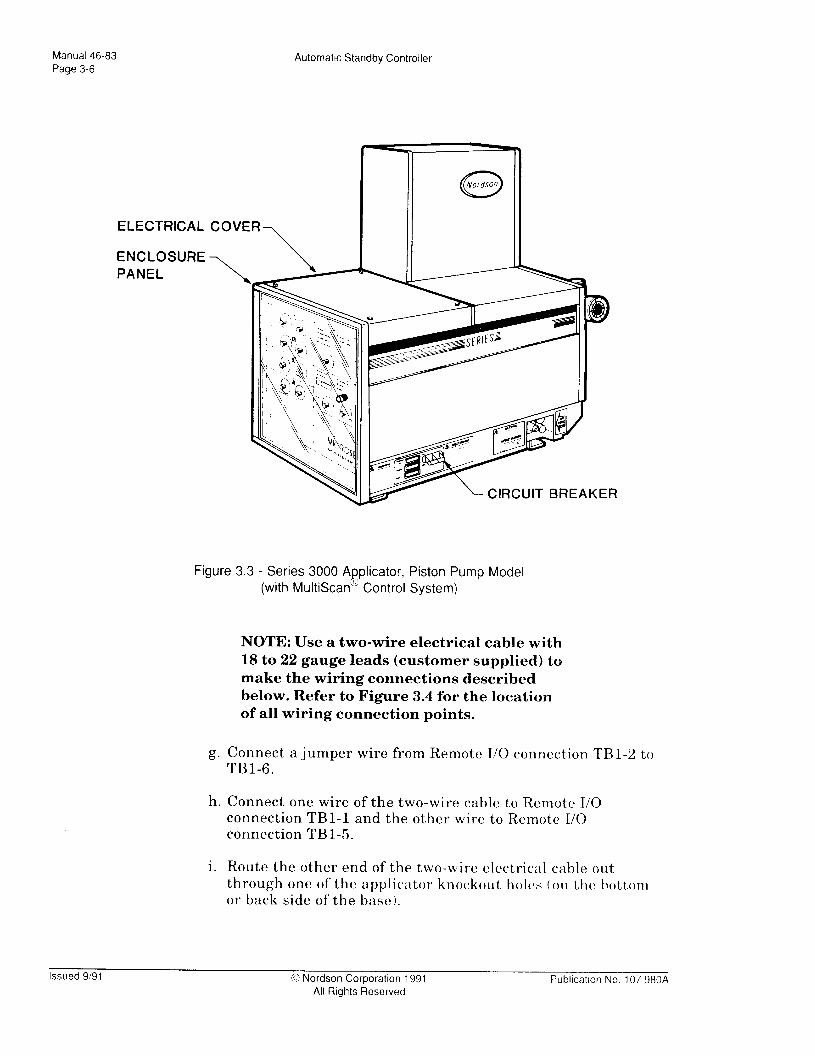
5. (Piston Pump units only) Install automatic temperature setback capability by doing the following:
a. Loosen the four captive screws that secure the electrical cover to the top of the applicator enclosure (Figure 3.3).
b. Remove the cover.
c. Loosen the two captive screws that secure the control frame to the applicator electrical control cabinet (Figure 3.3 ).
d. Carefully pull the enclosure panel (Figure 3.3) on each end of the control frame away from the frame while moving the control frame clear or the panel captive screws.
e. The control applicator
8 MultiScan ”
frame assembly pivots at the bottom of the nclosure. Swing it down and out to access the Remote I/O printed circuit board (Remote I/O ).
f. If not already installed, install the Remote I/O by following the instructions providled with the board kit.
Publication No. 107 980A 0 Nordson Corporation 1991 All Rights Reserved
Issued 9191
Manual 46-83
Page 3-6 Automatic Standby Controller
ELECTRICAL COVER
ENCLOSU
PANEL
RE
IRCUIT BREAKER -
Figure 3.3 - Series 3000 A e
plicator, Piston F’ump Model (with MultiScan R Control System)
NOTE: Use a two-wire electrical cable with 18 to 22 gauge leads (customer supplied) to make the wiring connections described below. Refer to Figure 3.4 for the location of all wiring connection points.
g. Connect a jumper wire from Remote I/O connection TBI-2 to TBl-6.
h. Connect one wire of the two-wire cable to Remote T/O connection TBl-1 and the other 7wire to Remote I/O connection TBl-5.
i. Route the other end of the two-wire electrical cable out through one of the applicator knockout, holy (on thv bott,om or back side of the base).
Issued 9191 0 Nordson Corporation 1991 All Rights Reserved
Publtcation No 107 980A

Automatic Standby Controller Manual 46-83 Page 3-7
AUTOMATIC STANDBY
CONTROLLER PCB -
I
G’ } TRIG
I:} RREEMsoETTE
1
STANDBY
REMOTE STANDBY
SHUTDOWN
I
T82
\ REMOTE I/O, PISTON PUMP, MULTISCAN@
Figure 3.4 - Controller to Series 3000 Piston Pump, Remote I/O Temperature Standby Electrical Connections
Publication No. 107 980A 0 Nordson Corporation 1991 All Rights Reserved
Issued 9’91

Manual 46-83 Page 3-8
Automatic Standby Controller
j. Route the cable into the Controller through either knockout hole (on the bottom of the unit).
k. Connect the wire from Remote I/O connection TBl-1 to Controller connection TBl-6. Connect the other wire from Remote I/O connection TBl-5 to Controller connection TBl-5.
1. If sleep enable capability is NOT being installed, go to step 11. Otherwise, continue with step 6, below.
6. (Piston Pump units only) Install automatic sleep enable capability by doing the following:
NOTE: Use a two-wire electrical cable with 18 to 22 gauge leads (customer supplied) to make the wiring connections described below. Refer to Figure 3.5 for the location of all wiring connection points.
a. Connect an 18-22 gauge jumper wire from Remote I/O connection TBl-2 to TBl-10.
b. Using a two-wire electrical cable (customer supplied), connect one wire to Remote I/O connection TBl-2. Connect the other wire to Remote I/O connection TBl-10.
c. Route the other end of the two-wire electrical cable out through one of the applicator knockout holes (on the bottom or back side of the base).
d. Route the cable into the Controller through either knockout hole (on the bottom of the unit).
e. Connect the lead from Remote I/O connection TBl-1 to Controller connection TB2-3. Connect the lead from Remote I/O connection TBl-9 to Controller connection TB2-4.
f. Go to step 11.
7. (Gear Pump units only) Install automatic temperature setback capability by doing the following:
a. Loosen the six captive screws that secure the electrical cover to the top of the applicator enclosure (Figure 3.6).
Issued 9191 0 Nordson Corporation 1991 All Rights Reserved
Publtcatlon No 107 980A

Automatic Standby Controller Manual 46-83
Page 3-9
AUTOMATIC STANDBY CONTROLLER PCB
\
REMOTE 51 c STANDBY X NC
a3 NO -c4 c 1 SHUTDOWN
TB2 ml rl El
REMOTE I/O, PISTON PUMP, MULTISCAN @
Figure 3.5 - Controller to Series 3000, Piston Pump, Remote I/O Sleep Enabled Electrical Connections
Pubkation No. 107 980A % Nordson Corporation 1991 All Rights Reserved
Issued 9!91
Manual 46-83 Page 3-l 0
Automatic Standby Controller
b. Remove the cover.
c. Remove the two bolts that secure the control frame to the applicator electrical control cabinet (Figure 3.6).
Figure 3.6 - Series 3000 A plicator, Gear Pump Model,
(with g
MultiScan ’ Control System)
d. Slide the control frame assembl,y out from the electrical control cabinet in order to access the MultiScan @ Remote I/O printed circuit board (Remote I/O).
e. If not already installed, install the Remote I/O by following the instructions provided with the board kit.
NOTE: Use a two-wire electrical cable with 18 to 22 gauge leads (customer supplied) to make the wiring connections described
Issued 9191 0 Nordson Corporation 1991 All Rights Reserved
Pubkatlon No. 107 980A

Automatic Standby Controller Manual 46-83 Page 3-11
AUTOMATIC STANDBY CONTROLLER PC8
TBl >
; N
SHUTDOWN
TB2 Ia
00000000 Jl 00000000 Ill
\ REMOTE I/O, GEAR PUMP, MULTISCAN 03
Figure 3.7 - Controller to Series 3000, Gear Pump, Remote I/O Temperature Setback Electrical Connections
Publlcatlon No. 107 980A 0 Nordson Corporation 1991 All Rights Reserved
Issued 9191

Manual 46-83 Page 3-l 2
Automatic Standby Controller
below. Refer to Figure 3.7 for the location of all wiring connection points.
f. Connect one wire of a two-wire cable to Remote I/O connection TBl-1 and the other wire to Remote I/O connection TBl-5.
g. Route the cable out through one of the applicator knockout holes (on the bottom or back side of the base).
h. Route the cable into the Controller through either knockout hole (on the bottom of the unit).
i. Connect the wire from Remote I/O connection TBI-1 to Controller connection TBl-6. Connect the other wire from Remote I/O connection TBl-5 to Controller connection TBl-5.
j. If sleep enable capability is NOT being installed, go to step 9.
8. (Gear Pump units only) Install automatic sleep enable capability by doing the following:
NOTE: Use a two-wire electrical cable with 18 to 22 gauge leads (customer supplied) to make the wiring connections described below. Refer to Figure 3.8 for the location of all wiring connection points.
a. Connect an 18-22 gauge jumper wire from Remote I/O connection TBl-2 to TBl-10.
b. Connect one wire of a two-wire electrical cable to Remote I/O connection TBl-2. Connect the other wire to Remote I/O connection TBl-10.
c. Route the cable out through one of the applicator knockout holes (on the bottom or back side of the base).
d. Route the cable into the Controller through either knockout hole (on the bottom of the unit).
e. Connect the wire from Remote I/O connection TBl-1 to Controller connection TB2-3. Connect the lead from Remote I/O connection TBl-9 to Controller connection TB2-4.
9. Close the applicator by doing the following (see Figure 3.3):
Issued 9/91 0 Nordson Corporation 1991 All Rights Reserved
Publication No 107 980A

Automatic Standby Controller Manual 46-83 Page 3-l 3
AUTOMATIC STANDBY CONTROLLER PCB
3 4
a
I 42
a
a
SHUTDOWN
REMOTE
I I 1 NC J SHUTDOWN
I TB2
q
I- Rk?!S;;E NO I-.-- n
C STANDBY NC
REMOTE
STANDBY
j i k ‘I] TB2 000000000000
00000000 Jl 00000000
REMOTE I/O, GEAR PUMP, MULTISCAN @
Figure 3.8 - Controller to Series 3000, Gear Pump, Remote I/O Sleep Enabled Electrical Connections
Publication No. 107 980A 0 Nordson Corporation 1991 All Rights Reserved
Issued 9191
Manual 46-83 Page 3-l 4
Automatic Standby Controller
a. Swing the control frame assembly up and back.
b. Carefully pull the enclosure panel on each end of the control frame away from the frame while aligning the control frame holes with the enclosure captive screws.
c. Tighten the two captive screws that secure the control frame to the applicator electrical control cabinet.
d. Replace the cover and tighten the four captive screws that secure the cover to the top of the applicator enclosure.
10. Set the Controller operating conditions as detailed in Section 4.
11. Close the Controller cover and s1id.e the Controller cabinet lock brackets over the front panel lip. Tighten the two retaining screws.
12. Restore input power to the applicator circuit breaker.
13. Follow the “DAILY START-UP PROCEDURE” in the applicator technical manual to restore the applicator to operation.
14. Restore input power to the Controller.
15. Flip the Controller circuit breaker to the ON position.
16. Resume system operation.
Issued 9/91 0 Nordson Corporation 1991 All Rights Reserved
Publication No 107 980A

Automatic Standby Controller
SERIES 2300 INSTALLATION
Manual 46-83 Page 3-l 5
NOTE: It is imperative that personnel installing this equipment refer to the applicator technical manual. The manual provides importiant safety, operation, and troubleshooting information used in conjunction with procedures presented in this manual.
Safety Precautions
A ‘r
WARNING: Even when switched off, the applicator contains energized components with electrical poten- tials that can cause death. When instructed to do so, follow these steps to ensure your safety:
1. Disconnect and lock out power to the main circuit breaker for the input power line to the applicator.
2. Avoid touching any energized applicator component.
A ‘I
WARNING: Even when switched off, the Controller contains energized components with electrical poten- tials that can cause death. Follow these steps to ensure your safety:
1. If input electrical power to the Controller is from a different source than the applicator: disconnect and lock out power to the main circuit breaker for the Controller input power line.
2. Avoid touching any energized Controller component.
WARNING: T:rapped air in the hoses and guns can cause spitting of air and molten adhesive, resulting in severe burns. Shield the area and the operator from splashed material before triggering guns to relieve hydraulic pressure.
Publication No. 107 980A 0 Nordson Corporation 1991 All Rights Reserved
Issued 9,91
Manual 46-83 Page 3-l 6
Automatic Standby Controller
A WARNING: Hanging a handgun by its trigger can result in accidental discharge of hot melt material, causing severe burns. If a handgun is being used, always hang it by the hsl43 in its handle.
A WARNING: Input voltage to the Controller must match the setting of the Controller input power switch (S4) or equipment damage will occur.
A WARNING: Contactor coil voltage must be the same as the voltage powering the Controller (120 VAC or 240 VAC) or the Controller will be damaged. Make sure to match voltage to avoid equipment damage.
Preliminary Installation Steps
1. If the applicator is not already installed, install it according to the procedures described in its technical manual.
2. If the applicator is a previously operated unit, follow the “DAILY SHUTDOWN PROCEDURE” in the applicator technical manual.
3. Disconnect and lock out input power to the applicator.
4. Install the Controller by doing the following:
a. Disconnect and lock out input power to the Controller.
b. Loosen the two Controller cabinet lock bracket screws and slide the brackets off the front panel lip (Figure 3.1).
c. Open the Controller front panel.
d. Locate the Controller input power switch (S4) on the PC board (Figure 3.2); set S4 to match the input power voltage source (115 VAC or 230 VAC).
e. Route a power cable (in accordance with all local electrical codes) from a disconnected and locked out single-phase input power voltage source (115 VA6 or 230 VAC) through the right knockout hole located on the bottom of the Controller.
f. Connect the cable to the two input connections and @ND (ground) on the Controller terminal block, TB3 (Figure 3.1).
Issued 9191 0 Nordson Corporation 1991 All Rights Reserved
Pubilcatlon No 107 980A

Automatic Stancby Controller Manual 46-83 Page 3-l 7
g. Route a wire from tlhe ground terminal lug spade (Figure 3.1) through one of the knockout holes located on the bottom of the Controller to an appropriate earth ground.
NOTE: To connect electrical wires to terminal block connections referenced in this part, first loosen the slot head screw for the specified connection; second, insert the bare end of tlhe electrical wire; then, tighten the slot head screw.
h. Route an appropriate control cable from the gun triggering device through one of the knockout holes located on the bottom of the Controller. Connect the cable to the Controller TRIG connection, TBl-1 and TBl-2, on PC board terminal block TBl (Figure 3#.2). The trigger signal may be 120 W4C or 24 VDC.
2300~Specific Installation Procedures
There may be several different installation procedures to follow, depending on (1) whether standby condition capability and/or shutdown enabled capability is desired, and (2) the configuration of the 2300~series applicator.
Refer to the flow chart on the next page to determine which installation steps to follow.
Publicatton No. 107 980A 0 Nordson Corporation 1991 All Rights IReserved
Issued 9’91

Manual 46-83 Page 3-l 8
Automatic Standby Controller
Determine the system con- figuration.
I YES I
Temperature Setback Interface
Follow step 3, “Installing the
[ Go to “Final Installation Steps.”
Enable Installation.”
1. Installing Temperature Setback - Follow steps 1 through 13 of the instructions included with the Temperature Setback Conversion Kit, P/N 276 587 (see Figure 3.9 for location of assemblies referenced>.
2. Installing the Temperature Setback Interface Kit (P./N 276 587).
a. Follow steps 3 and 4 only of the instructions included with the Temperature Setback Interface Kit (P/N 276 510 1
b. Do one of the following:
(1) If you are going to add Option&s Interface capability go to step 3, below.
Issued 9/91 0 Nordson Corporation 1991 All Rights Reserved
Pubkation No 107 980A

Automatic Standby Controller Manual 46-83
Page 3-l 9
CAPTIVE SCREW
ENCLOSURE
CONTRO
FRAME
ASSEMB CIRCUIT BREAKER
Figure 3.9 - Series; 2300 Applicator
(2) If you are not adding the Options Interface, but want to add Shutdown capability, go to step 4.
(3) If you do not want Options Interface or Shutdown capability, go to step 7.
3. Installing the Options Interface Kit
a. Read the Equipment Description, Safety Precautions, and Unpacking Instructions paragraphs of the instructions included with the Options Interface Conversion Kit (P/N 104 487).
b. Start with step 2 in the Options Interface Board Installation paragraph and follow all the steps through step 23 (page 7 of the instructions).
Pubkation No. 107 980A 0 Nordson Corporation 1991 All Rights Fleserved
Issued 9/91

Manual 46-83 Page 3-20
Automatic Standby Controller
NOTE: Use 18 gauge electrical leads (customer supplied) to make the connections descri.bed below.
c. Connect one end of an electrical lead to Controller connection TBl-8 on terminal block TBl (Figure 3.2).
d. Connect one end of a second electrical lead (customer supplied) to Controller connection TB2-1 on terminal block TB2 (Figure 3.2).
e. Route the leads:
(1) Out through eith er of the knockouts on the bottom of the Controller;
(2) Into the applicator through the cord access hole for the input power leads; and
(3) To connectors TB2-1 and TB2-2 on Options Interface Board terminal block TB2 (Figure 3.10).
f. Connect the lead from Controller connection TBl-8 to Options Interface Board connection TB2-2 on terminal block TB2.
g. Connect the lead from Controller connection TB2-1 to Options Interface Board connection TB2-1 on terminal block TB2.
h. Complete steps 2 and 3 of the Options Interface Board Conversion Kit instructions (page 7) for the other options you want to connect.
i. If you do NOT want Shutdown Enabled, go to step 5. Other- wise, continue below.
4. Shutdown Enabled Installation - In order for the Controller to shutdown power to the 2300-series applicators, a customer supplied contactor must be installed between the Controller and applicator.
NOTE: Nordson recommends the use of a 4=pole, closed (cabinet) contactor rated at 60 amps or greater and mounted outside the Controller and applicator.
Issued 9/91 0 Nordson Corporation 1991 All Rights Reserved
----- Publlcatlon r\io 107 98OA

Automatic Standby Controller Manual 46-83 Page 3-21
AUTOMATIC STANDBY CONTROLLER PCB
i TBl
t TRIG
NO C NC
NO
C NC
NO C NC NO C NC
I TB2
STANDBY
JU
cl
REMOTE
STANDBY
SHUTDOWN
REMOTE
SHUTDOWN 0
r- OPTIONS INTERFACE
BOARD TB2
___ J16 1
-e -
-+-x7 2 -
3 0
7-+ tl
4 0 -A@- : -
5 0 -
---(tl
6 0 --+J -
7 0 -
--(tl
8 l -49 ’
9 l --eL 10 0 --xc -
11 l -
--+I ,
q-- I
-?-Ll --
- -
Figure 3.10 - Controller to Series 2300 Applicator Electrical Connections
r SERIES 2300 APPLICATOR
Pubkation No. 107 980A G Nordson Corporation 1991 All Rights Reserved
Issued 9191

Manual 46-83 Page 3-22
Automatic Standby Controller
a. Disconnect and lock out input power to the applicator.
b. If Controller input power does NOT come from the applicator, disconnect and lock out input power to the Controller
c. Flip the Controller circuit breaker to the OFF position.
d. Install the contactor between the Controller and applicator by doing the following:
(1) Mount a 4 -pole, 60A closed contactor (in accordance with all local electrical codes) to a suitable mounting location out- side both the Controller and applicator.
(2) Open the contactor cabinet.
(3) Make sure that contactor coil voltage is the same as the voltage setting of Controller input power switch, S4 (see Figure 3.2). Otherwise, equipment damage can occur.
NOTE: If connecting the contactor to a single-phase 2300 applicator, use three- wire power cables to connect to input power and the applicator. If coanecting the contactor to a three-phase 2300 applicator, use four-wire power cables to conuect to input power and the applicator.
NOTE: Refer to Figure 3.11 for the location of all contactor to Controller wiring conuec- tion points discussed below.
(4) Connect the leads of a three- or four-wire power cable (customer supplied) to the load side of the contactor. These wires must be the standard size as required for typical Series 2300 power hook ups.
(5) Route th e opposite end of the contactor load side cable through the applicator cord access hole to 2300 terminal block TBl.
(6) Connect the contactor load side leads to 2300 input conncc- tions Ll, L2 and/or L3, and N. These wires must also be
Issued 9/91 0 Nordson Corporation 1991 All Rights Reserved
-.-___ Publication No 107 9804

AutomaW Standby Controller Manual 46-83 Page 3-23
AUTOMATIC STANDBY
CONTROLLER
TB2 _/
120 OR 240 VAC
/TB3
LINE VOLTAGE TO APPLICATOR
TOR
2300 APPLICATOR
- -----I-J
Figure 3.11 - Electrical Connections for Installation of Contactor Between Controller and 2300 Applicator
/TBl
Publwtton No 107 980A 1~ Nordson Corporation 1991 All Rights Reserved
Issued 9) 91

Manual 46-83 Page 3-24
Automatic Standby Controller
the standard size as required for typical Series 2300 power hook ups.
(7) Connect one side of the contactor coil to Controller connec- tion TB2-4.
(8) Connect th e other side of the contactor coil to Controller con- nection TB3-2.
(9) Connect a jumper wire between Controller connections TB3- 1 to TB2-5.
(10) Connect the leads of another t,hree- or four-wire power cable (customer supplied) to the line side connectors on the contactor. These wires must be the standard size as required for typical Series 2300 power hook ups.
(11) Route the opposite end of the contactor line side cable to the input voltage source for the applicator.
Final Installation Steps
1. Close the contactor cabinet.
2. Replace the applicator electrical cabinet enclosure and tighten the captive screw on top of the cabinet that secures it.
3. Close the Controller front panel and slide the two cabinet latches (Figure 3.1) over the front panel lip.
4. Tighten the two screws that secure the cabinet latches (Figure 3.1).
5. Set the Controller operating conditions as detailed in Section 4.
6. Close the Controller cover and slide the Controller cabinet lock brackets over the front panel lip. Tighten the two retaining screws.
7. Restore input power to the applicator.
8. Follow the “DAILY START-UP PROCEDURE” in the applicator technical manual to restore the applicator to operation.
9. Restore input power to the Controller.
10. Resume system operation.
Issued 9/91 0 Nordson Corporation 1991 All Rights Reserved
Publlcatlon No. 107 980A

Automatic Starldby Controller
SERIES 6000 INSTALLATION
Manual 46-83 Page 3-25
NOTE: It is imperative that personnel installing this equipment refer to the applicator technical manual. The manual provides important safety, operation, and troubleshooting information used in conjunction witlh procedures presented in this manual.
Safety Precautions
A ‘I
WARNING: Even when switched off, the applicator contains energized components with electrical poten- tials that can cause death. When instructed to do so, follow these steps to ensure your safety:
1. Disconnect and lock out power to the main circuit breaker for the applicator input power line.
2. Avoid touching any energized applicator component.
A WARNING: Even when switched off, the Controller
‘I contains energized components with electrical poten- tials that can cause death. When instructed to do so, follow these steps to ensure your safety:
1. If input electrical power to the Controller is from a different source than the applicator: disconnect and lock out power to the main circuit breaker for the Controller input power line.
2. Avoid touching any energized Controller component.
A WARNING: T:rapped air in the hoses and guns can cause spitting of air and molten adhesive, resulting in severe burns. Shield the area and the operator from splashed material before triggering guns to relieve hydraulic pressure.
Publlcatlon No. 107 980A G Nordson Corporation 1991 All Rights Fleserved
Issued 9191

Manual 46-83
Page 3-26
Automatic Standby Controller
A
A
WARNING: Hanging a handgun by its trigger can result in accidental discharge of hot melt material, causing severe burns. If .a handgun is being used, always hang it by the holle in its handle.
WARNING: Input voltage to the Controller must match the setting of the Controller input power switch (S4) or equipment damage will occur.
Introduction
Series 6000 installation is divided into four parts:
l Preliminary Series 6000 Installation Steps
l Non-Universal Machine Interface Steps (if installing a unit with UMI, skip this part)
l Universal Machine Interface-specific Steps (if installing a unit without UMI, skip this part)
l Final Series 6000 Installation Steps
Preliminary Series 6000 Installation Steps
1. If the applicator is not already installed, install it according to the procedures described in its technical manual.
2. If the applicator is a previously operated unit, follow the “DAILY SHUTDOWN PROCEDURE” in the applicator technical manual.
3. Disconnect and lock out input power to the applicator.
4. Install the Controller by doing the following:
a. If input electrical power to the Controller is from a different source than the applicator, disconnect and lock out input power to the Controller.
b. Loosen the two Controller cabinet lock bracket screws and slide the brackets off the front panel lip (Figure 3.2~.
c. Open the Controller front panel.
d. Locate the Controller input power switch (S4) on the PC board (Figure 3.2); set S4 to match the input power voltage source (115 VAC or 230 VAC).
Issued 9/91 0 Nordson Corporation 1991 All Rights Reserved
Pubkatlon No 107 380A

Automatic Standby Controller Manual 46-83 Page 3-27
NOTE: Use a two-wire electrical cable with 18 to 22 gauge leads (customer supplied) to make the wiring connections described below.
e. Route a power cable (in accordance with all local electrical codes) from a disconnected and locked out single-phase input power voltage source (115 VAC or 230 VAC) through the right knockout hole located on the bottom of the Controller.
NOTE: To connect electrical wires to terminal block connections referenced in this part: first, loosen the slot head screw for the specified connection; second, insert the bare end of the electrical wire; then, tighten the slot head screw.
f. Connect the cable tlo the two input connections and GND (ground) on the Controller terminal block, TB3 (Figure 3.2).
g. Route a wire from the ground terminal lug spade through one of the knockout holes located on the bottom of the Controller to an appropriate e#arth ground.
h. Route an appropriate control cable from the gun triggering device through one of the knockout holes located on the bottom of the Controller. Connect the cable to the TRIG connection, TBl-1 and TBl-2, on PC board terminal block TBl (Figure 3.2). The trigger signal may be 120 VAC or 24 VDC.
Pubkation No. 107 980A 0 Nordson Corporation 1991 All Rights Reserved
Issued 9191

Manual 46-83 Page 3-28
Automatic Standby Controller
Non-Universal Machine Interface Steps
These units are equipped with Standby Temperature Control, but do NOT have the Universal Machine Interface. Install automatic temperature setback capability by doing the following:
1. Open the applicator electrical enclosure door by loosening the quarter-turn fasteners.
2. If not already installed, install the needed 6000 equipment (refer to Table 2.5).
NOTE: Use two-wire electrical cable with 18 to 22 gauge wires (customer supplied) to make the following electrical connections. Refer to Figure 3.12 for the location of all wiring connection points.
3. Connect one wire to connection TB12-1 on the applicator connector board.
4. Connect the other wire to applicator connection TB2-2 on the connector board.
5. Route the cable out through the hole located on the bottom right- hand side of the applicator electrical cabinet.
6. Route the cable into the Controller through either knockout hole (on the bottom of the unit).
7. Connect the opposite end of the wire from applicator connector board connection TB2-1 to Controller board connection TBl-5.
8. Connect the opposite end of the wire from applicator connector board connection TB2-2 to Controller connection TBl-6.
NOTE: If sleep enable capability is NOT being installed, go to “Final Series 6000 Installation Steps”. Otherwise, continue with step 9.
9. Install automatic sleep enable capability by doing the following:
Issued 9191 0 Nordson Corporation 1991 All Rights Reserved
Pubkcation No 107 980A
Automatic Standby Controller Manual 46-83 Page 3-29
a. Connect one wire to applicator connector board connection TBl-1.
b. Connect the other wire to applicator connector board connec- tion TB l-2.
AUTOMATIC STANDBY CONTROLLER PCB -\
TBl D-a
g’ } TRIG
SHUTDOWN
REMOTE SHUTDOWN
TB2 ICI
L SERIES 6000 CONNECTOR BOARD
Figure 3.12 - Controller to Series 6000 Applicators (without UMI) Electrical Connections
Publication No. 107 980A 0 Nordson Corporation 1991 All Rights Reserved
Issued 9191

Manual 46-83
Page 3-30
Automatic Standby Controller
c. Route the cable out through the hole located on the bottom right-hand side of the applicator electrical cabinet.
d. Route the cable into the Controller through either knockout hole (on the bottom of the unit).
e. Connect the wire from applicator connector board connection TBI-1 to Controller connection TB2-5.
f. Connect the opposite end of the wire from applicator connector board connection TBl-2 to Controller connection TB2-4.
f. Go to “Final Series 6000 Installation Steps.”
Universal Machine Interface-specific Steps
If not installing a unit with UMI, go to “Final Series 6000 Installation Steps.”
1. Open the applicator electrical enclosure door by loosening the quarter-turn fasteners.
2. If not already installed, install the Universal Machine Interface (UMI) by following the instructions in the UMI kit.
NOTE: Use two-wire electrical cable with 18 to 22 gauge wires (customer supplied) to make the following electrical connections. Refer to Figure 3.13 for the location of all wiring connection points.
3. Connect one wire to UMI pin connection 33.
4. Connect the other wire to UMI pin connection 34.
5. Route the cable out through the hole located on the bottom right- hand side of the applicator electrical cabinet.
6. Route the cable into the Controller through either knockout hole (on the bottom of the unit).
7. Connect the opposite end of the wire from UMI pin 33 to Controller connection TB l-5.
8. Connect the opposite end of the wire from UMI pin 34 to Controller connection TB l-6.
Issued 9191 0 Nordson Corporation 1991 All Rights Reserved
Publication No. 107 980A

Automatic Standby Controller Manual 46-83 Page 3-31
TB2
TBl >
: N
SHUTDOWN
REMOTE:
SHUTDOWN
AUTOMATIC STANDBY INPUTS CONTROLLER PCB
025 370
026 380
027 390
028 400
029 410
030 420
031 430
032 440
-033 450
a34 460
-035 470
-036 480
’ UMI CONNECTOR
Figure 3.13 - Controller to Series 6000 Applicators (with UMI) Electrical Connections
NOTE: If sleep enable capability is NOT being installed, go to “Final Series 6000 Installation Steps”. Otherwise, continue to step 9.
Publication No. 107 980A 0 Nordson Corporation 1991
All Rights Reserved Issued 9191

Manual 46-83 Page 3-32
Automatic Standby Controller
9. Install automatic sleep enable capability by doing the following:
a. Connect one wire to UMI pin connection 35.
b. Connect the other wire to UMI pin connection 36.
c. Route the cable out through the hole located on the bottom right-hand side of the applicator electrical cabinet.
d. Route the cable into the Controller through either knockout hole (on the bottom of the unit).
e. Connect the wire from UMI pin :35 to Controller connection TB2-3.
f. Connect the lead from UMI pin 36 to Controller connection TB2-4.
Final Series 6000 Installation Steps
1. Close the applicator and tighten the quarter-turn fasteners.
2. Set the Controller operating conditions as detailed in Section 4.
3. Close the Controller cover and slide the Controller cabinet lock brackets over the front panel lip. Tighten the two retaining screws.
4. Follow the “DAILY START-UP PROCEDURE” in the applicator technical manual to restore the applicator to operation.
5. Restore input power to the Controller.
6. Flip the Controller circuit breaker to the ON position.
7. Resume system operation.
Issued 9/91 0 Nordson Corporation 1991 All Rights Reserved
Pubkation No 107 980A

Automatic Standby Controller Manual 46-83
Page 3-33
PRE-LCU BULK MELTER INSTALLAII’ION (Models500,5505,5510,5520)
NOTE: It is imperative that personnel installing this equipment refer to the bulk melter’s technical manual. The manual provides important safety, operation, and troubleshooting information used in conjunction with procedures presented in this manual.
Safety Precautions
n WARNING: Even when switched off, the bulk melter
‘I contains energized components with electrical poten- tials that can cause death. When instructed to do so, follow these steps to ensure your safety:
1. Disconnect and lock out power to the main circuit breaker for the bulk melter input power line.
2. Avoid touching any energized bulk melter component.
WARNING: Elven when switched off, the Controller contains energized components with electrical poten- tials that can cause death. When instructed to do so, follow these steps to ensure your safety:
1. If input electrical power to the Controller is from a different source than the bulk melter: disconnect and lock out power to the main circuit breaker for the Controller input power line.
2. Avoid touching any energized bulk melter or Controller component.
A WARNING: Trapped air in the hoses and guns can cause spitting of air and molten adhesive, resulting in severe burns. Shield the area and the operator from splashed material before triggering guns to relieve hydraulic pressure.
Publication No. 107 980A 3 Nordson Corporation 1991 All Rights Reserved
Issued 9191
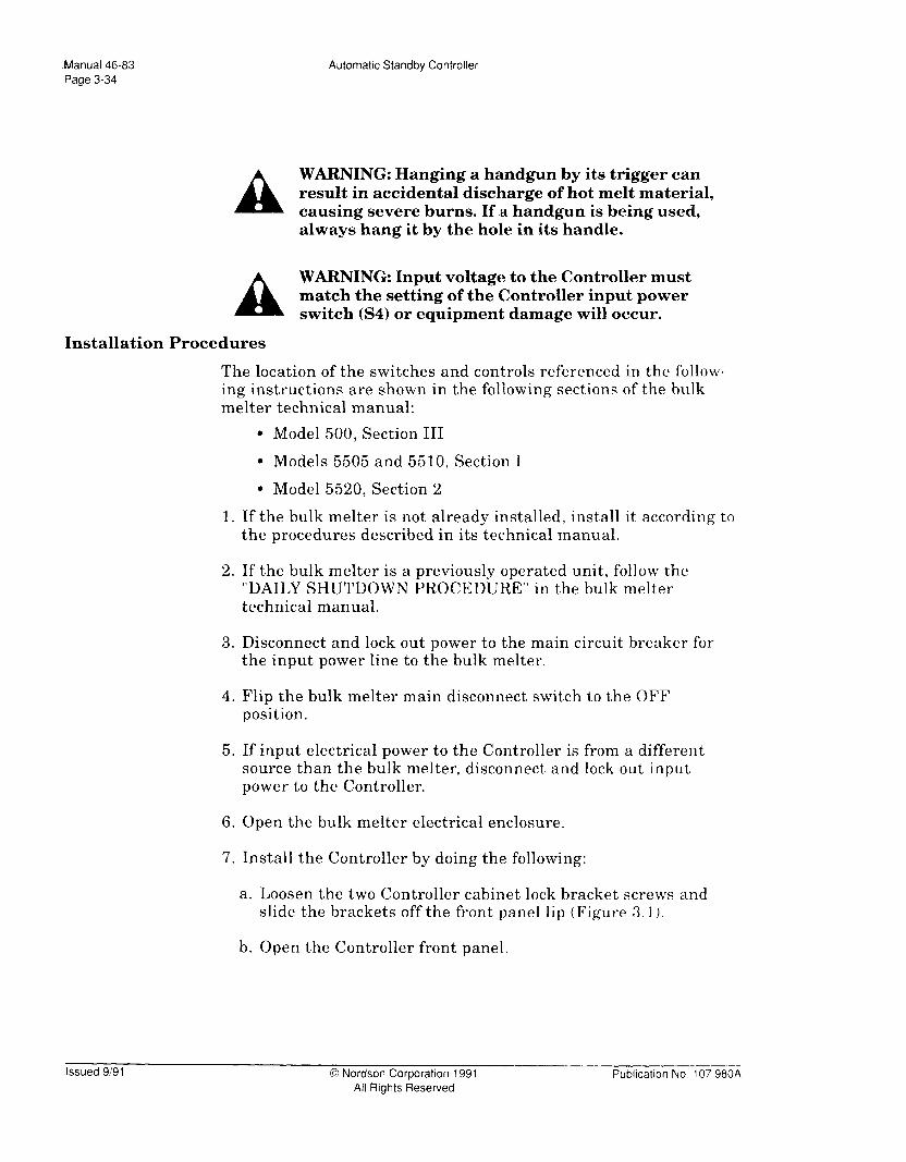
Manual 46-83 Page 3-34
Automatic Standby Controller
A WARNING: Hanging a handgun by its trigger can result in accidental discharge of hot melt material, causing severe burns. If a handgun is being used, always hang it by the hole in its handle.
A WARNING: Input voltage to the Controller must match the setting of the Controller input power switch (S4) or equipment damage will occur.
Installation Procedures
The location of the switches and controls referenced in the follow- ing instructions are shown in the following sections of the bulk melter technical manual:
l Model 500, Section III
l Models 5505 and 5510, Section I
l Model 5520, Section 2
1. If the bulk melter is not already installed, install it according to the procedures described in its technical manual.
2. If the bulk melter is a previously operated unit, follow the “DAILY SHUTDOWN PROCEDURE” in the bulk melter technical manual.
3. Disconnect and lock out power to the main circuit breaker for the input power line to the bulk melter.
4. Flip the bulk melter main disconnect switch to the OFF position.
5. If input electrical power to the Controller is from a different source than the bulk melter, disconnect and lock out input power to the Controller.
6. Open the bulk melter electrical enclosure.
7. Install the Controller by doing the following:
a. Loosen the two Controller cabinet lock bracket screws and slide the brackets off the front panel lip (Figure 3.1).
b. Open the Controller front panel.
Issued 9/91 0 Nordson Corporation 1991 All Rights Reserved
Publication No 107 980x

Automatic Standby Controller Manual 46-83
Page 3-35
c. Locate the Controller input power switch (S4) on the board (Figure 3.2); set S4 to match the input power voltage source (115 VAC or 230 WC).
d. Route a power cablle (in accordance with all local electrical codes) from a disconnected and locked out single-phase input power voltage source (115 VAC or 230 VAC) through the right knockout hole located on the bottom of the Controller.
NOTE: To connect electrical wires to terminal block connections referenced in this part: first, loosen the slot head screw for the specified connection; second, insert the bare end of the electrical wire; then, tighten the slot head screw.
e. Connect the cable to the two input connections and GND (ground) on the Controller terminal block, TB3 (Figure 3.2).
f. Route a wire from the ground terminal lug spade through one of the knockout holes located on the bottom of the Controller to an appropriate e#arth ground.
g. Route an appropriate control cable from the gun triggering device through one of the knockout holes located on the bottom of the Controller. Connect the cable to the TRIG connection, TBl-1 and TBl-2, on PC board terminal block TBl (Figure 3.2). The trigger signal may be 120 VAC or 24 VDC.
9. Install automatic standby by doing the following:
a. Locate the back of t,he bulk melter Platen Temperature Controller (PTC) on the inside of the electrical box assembly door.
Publication No. 107 980A 0 Nordson Corporation 1991 All Rights Reserved
Issued 9/91

Manual 46-83
Page 3-36 Automatic Standby Controller
NOTE: Use 18 gauge wire (customer supplied) to make the wiring connections described below.
b. Cut wire 18 (connected to PTC terminal 4) about 3 inches from PTC terminal 4.
c. Connect an 18 gauge wire to the end of wire 18 that is still connected to the PTC.
d. Route the opposite end of that wire into the Controller through the knockout hole on the left side of the Controller.
e. Connect the wire to Controller connection TBl-6 on terminal block TBl (Figure 3.2). The trigger signal may be 120 VAC or 24 VDC.
f. Connect another 18 gauge wire to Controller connection TBl-7 on terminal block TBl (Figure 3.2).
g. Route the opposite end of that wire into the bulk melter and connect it to the remaining end of wire 18.
h. If automatic shutdown capabilit,y is NOT being installed, go to step 11.
10. Install automatic shutdown by doing the following:
a. Locate the back of the bulk melter stop switch (Sl> on the inside of the electrical box assembly door.
b. Cut wire 9B (connected to the stop switch) about 3 inches from the stop switch.
c. Connect one end of an 18 gauge wire to the end of wire 9B still connected to the stop switch.
Issued 9/91 0 Nordson Corporation 1991 All Rights Reserved
Publication No. 107 980A

Automatic Standby Controller Manual 46-83 Page 3-37
d. Route the opposite end of that wire into the Controller through the knockout hole on the left side of the Controller.
e. Connect the wire to Controller connection TB2-4 on terminal block TB2 (Figure 3.2).
f. Connect another 18 gauge wire to Controller connection TB2-5 on terminal block TB2 (Figure 3.2).
g. Route the opposite end of that wire into the bulk melter and connect it to the remaining end of wire 9.
11. Close and secure the ‘bulk melter electrical box assembly door.
12. Set the Controller operating conditions as detailed in Section 4.
13. Restore input power to the bulk melter main disconnect switch.
14. Follow the “DAILY START-UP PROCEDURE” in the bulk melter manual to restore the bulk melter to operation.
15. Close the Controller front panel.
16. Slide the Controller cabinet lock brackets over the front panel lip and tighten the two bracket screws.
17. Restore input power to the Controller.
18. Flip the Controller circuit breaker to the ON position.
19. Resume system opera.tion.
Publication No. 107 980A 0 Nordson Corporation 1991 All Rights Reserved
Issued 9191

Manual 46-83 Page 3-38
Automatic Standby Controller
Series 5000 LCU BULK MELTER INSTALLATION (Models 505,506,5506,551,5530,5540,5550,5551)
NOTE: It is imperative that personnel installing this equipment refer to the bulk melter’s technical manual. The manual provides important safety, operation, and troubleshooting information used in conjunction with procedures presented in this manual.
Safety Precautions
WARNING: Even when switched off, the bulk melter contains energized components with electrical poten- tials that can cause deathi. When instructed to do so, follow these steps to ensure your safety:
1. Disconnect and lock out power to the main circuit breaker for the bulk melter input power line.
2. Flip the bulk melter main disconnect switch to the off position.
3. Avoid touching any energized bulk melter component.
WARNING: Even when switched off, the Controller contains energized components with electrical poten- tials that can cause death.. When instructed to do so, follow these steps to ensure your safety:
1. If input electrical power to the Controller is from a different source than the bulk melter: disconnect and lock out power to the main circuit breaker for the Controller input power line.
2. Avoid touching any energized bulk melter or Controller component.
A WARNING: Trapped air in hoses and guns can spit hot air and adhesive which can burn people in the area. Shield the area and the operator before trigger- ing gun(s) to relieve hydr.aulic pressure.
Issued 9191 0 Nordson Corporation 1991 All Rights Reserved
Publication No. 107 980A

Automatic Standby Controller Manual 46-83 Page 3-39
A WARNING: Input voltage to the Controller must match the setting of the Controller input power switch (S4) or equipment damage will occur.
Installation Procedures
NOTE: Refer to Section 2 of the bulk melter technical manual for the location of the switches and controls referenced in the following instructions.
1. If the bulk melter is not already installed, install it according to the procedures described in its technical manual.
2. If the bulk melter is a previously operated unit, follow the “DAILY SHUTDOWN PROCEDURE” in the bulk melter technical manual.
3. Disconnect and lock out power to the main circuit breaker for the input power line to the bulk melter.
4. Flip the bulk melter main disconnect switch to the OFF position.
5. If input electrical power to the Controller is from a different source than the bulk melter, disconnect and lock out input power to the Controller.
6. Open the bulk melter electrical enclosure.
7. Install the Controller by doing the following:
a. Loosen the two Controller cabinet lock bracket screws and slide the brackets off the front panel lip (Figure 3.1).
b. Open the Controller front panel.
c. Locate the Controller input power switch (S4) on the PC board (Figure 3.2); set S4 to match the input power voltage source (115 VAC or 230 VAC).
d. Route a power cable (in accordance with all local electrical codes) from a disconnected and locked out single-phase input power voltage source (115 VAC or 230 VAC) through the right knockout hole located on the bottom of the Controller.
Publication No. 107 980A 0 Nordson Corporation 1991 All Rights Reserved
Issued 9191

Manual 46-83 Page 3-40
Automatic Standby Controller
NOTE: To connect electrical wires to terminal block connections referenced in this part: first, loosen the slot head screw for the specified connection; second, insert the bare end of the electrical wire; then, tighten the slot head screw.
e. Connect the cable to the two input connections and GND (ground) on the Controller terminal block, TB3 (Figure 3.2).
f. Route a wire from the ground terminal lug spade (Figure 3.1) through one of the knockout holes located on the bottom of the Controller to an appropriate earth ground.
g. Route an appropriate control cable from the gun triggering device through one of the knockout holes located on the bottom of the Controller. Connect the cable to the TRIG connection, TBl-1 and TBl-2, on PC board terminal block TBl (Figure 3.2). The trigger signal may be 120 VAC or 24 VDC.
8. Install automatic standby by doing the following:
a. If not already installed, install the Standby Module (P/N 816 270).
b. Locate the back of the bulk melter Platen Temperature Controller (PTC) on the inside o.f the electrical box assembly door.
c. Ensure that the standby switch, SA2, is to the ON position.
d. Locate the terminal block on bulk melter adapter card, C2 (Figure 3.13).
NOTE: Use 22 gauge wire (customer supplied) to make the wiring connections described below.
e. Connect one end of a 22 gauge wire to pin 13.
f. Route the other end of that wire into the Controller t!hrough the knockout hole on the left side of the Controller.
Issued 9/91 0 Nordson Corporation 1991 All Rights Reserved
- Publicatton No. 107 980A

Automatic Starldby Controller Manual 46-83 Page 3-41
Figure 3.14 - Location of Bulk Melter Adapter Card,
g. Connect the wire to Controller connection TBl-5 on terminal block TBl (Figure 3.2).
h. Connect another 22: gauge wire to Controller connection TBl-6 on terminal block TBl (Figure 3.2).
i. Route the other end of that wire into the bulk melter and connect it to C2, pin 5.
j. If automatic shutdown capability is NOT being installed, skip to step 10.
9. Install automatic shutdown by doing the following:
NOTE: Do NOT alttempt to install the Controller if the bulk melter Auto Shut- down Kit (P/N 816 004) is already installed.
a. Locate bulk melter terminal block XT2.
Publication No. 107 980A 0 Nordson Corporation 1991 All Rights Fleserved
Issued 9191

Manual 46-83 Page 3-42
Automatic Standby Controller
b. Connect one end of an 18 gauge Iwire to pin XT2-9.
c. Route the opposite end of that wire into the Controller through the knockout hole on the left side of the Controller.
d. Connect the wire to Controller connection TB2-4 on terminal block TB2 (Figure 3.2).
e. Connect another 18 gauge wire to Controller connection TB2-5 on terminal block TB2 (Figure 3.2).
f. Route the other end of that wire into the bulk melter and connect it to pin XT2-10.
g. Remove the shorting bar at XT2-9 and XT2-10.
10. Close and secure the bulk melter electrical box assembly door.
11. Set the Controller operating conditions as detailed in Section 4.
12. Close the Controller cover and slide the Controller cabinet lock brackets over the front panel lip. Tighten the two retaining screws.
13. Restore input power to the bulk melter main disconnect switch.
14. Follow the “DAILY START-UP PROCEDURE” in the bulk melter manual to restore the bulk melter to operation.
15. Restore input power to the Controller.
16. Resume system operation.
Issued 9191 0 Nordson Corporation 1991 All Rights Reserved
Publication No. 107 980A

Automatic Standby Controller Manual 46-83 Page 3-43
S-CHANNEL TEMPERATURE CONTROLLER INSTALLATION
For clarity, the g-channel Temperature Controller will be referred to as the “Temperature Controller” throughout these procedures. The Automatic Standby Controller will be referred to as the “Standby Controller”.
NOTE: It is imperative that personnel installing this equipment refer to the g-channel Temperature Controller technical manual. The manual provides important safety, operation, and troubleshooting information used in conjunction with procedures presented in this manual.
Safety Precautions
A ‘r
A 5
WARNING: Even when switched off, applicators and bulk melters contain energized components with electrical pot,entials that can cause death. When instructed to do so, follow these steps to ensure your safety:
1. Disconnect and lock out power to the main circuit breaker for the input power line to the applicator or bulk melter.
2. Avoid touching any energized applicator or bulk melter component.
WARNING: Even when switched off, the Tempera- ture Controller contains energized components with electrical pot.entials that can cause death. When instructed to do so, follow these steps to ensure your safety:
1. If input electrical power to the Temperature Controller is from a different source than the applicator or bulk melter:
a. Disconnect and lock out power to the main circuit breaker for the Temperature Controller input power line.
Publication No 107 980A 6 Nordson Corporation 1991 All Rights Reserved
Issued 9191

Manual 46-83
Page 3-44 Automatic Standby Controller
b. Flip the Temperature Controller circuit breaker to the off position.
2. Avoid touching any energized component in the Temperature Controller.
A ‘I
WARNING: Even when switched off, the Standby Controller contains energized components with electrical potentials that can cause death. When instructed to do so, follow these steps to ensure your safety:
1. If input electrical power to the Standby Control- ler is from a different source than the applicator or bulk melter: disconnect and lock out power to the main circuit breaker for the Standby Controller input power line.
2. Avoid touching any energized Standby Control- ler component.
A WARNING: Trapped air in the hoses and guns can cause spitting of air and molten adhesive, resulting in severe burns. Shield the area and the operator from splashed material before triggering guns to relieve hydraulic pressure.
A WARNING: Hanging a handgun by its trigger can result in accidental discharge of hot melt material, causing severe burns. If al handgun is being used, always hang it by the hole in its handle.
A WARNING: Input voltage to the Controller must match the setting of the Controller input power switch (S4) or equipment damage will occur.
A WARNING: Contactor coil voltage must be the same as the voltage powering the Standby Controller (120 VAC or 240 VAC) equipment damage will occur. Make sure to match voltage to avoid equipment damage.
Issued 9/91 0 Nordson Corporation 1991 All Rights Reserved
Pubkation No. 107 980A

Automatic Standby Controller Manual 46-83 Page 3-45
Preliminary Installation Steps
1. If the applicator or bulk melter is not already installed, install it according to the procedures described in its technical manual.
2. If the applicator or bulk melter is a previously operated unit, fol- low the “DAILY SHUTDOWN PROCEDURE” in the unit’s technical manual.
3. Disconnect and lock out power to the main circuit breaker for the input power line to the applicator or bulk melter.
4. If input electrical power to the Controller is from a different source than the applicator or bulk melter, disconnect and lock out input power to the Controller.
5. If the Temperature Controller is not already installed, install it according to the procedures described in its technical manual.
6. If the Temperature Controller is a previously operated unit, do the following:
Prepare to open the Temperature Controller by doing the following:
a. Disconnect and lock out power to the main circuit breaker for the Temperature Controller input power line.
b. Flip the Temperature Controller circuit breaker to the off position.
Publication No. 107 980A 0 Nordson Corporation 1991 All Rights Resewed
Issued 9191

Manual 46-83 Page 3-46
Automatic Standby Controller
c. Remove the electrical cabinet enclosure by loosening the captive screw on top of the enclosure and lifting the enclosure off the Temperature Controller (Figure 3.15).
ELECTRIC
CABINET ENCLOSURE
CONTROL FRAME ASSEMBLY
SCREW
-CIRCUIT
BREAKER
Figure 3.15 - g-Channel Temperature Controller
d. Loosen the two Temperature Controller control frame screws (located behind th f e rame assembly inside the electrical enclosure) that secure the control frame to the enclosure.
e. Swing the control frame assemblly forward and down to access the printed circuit board.
Standby Controller Installation
1. Disconnect and lock out input power to the Standby Controller.
2. Loosen the two Standby Controller cabinet lock bracket screws and slide the brackets off the front panel lip (Figure 3.1).
3. Open the Standby Controller front panel.
Issued 9/91 0 Nordson Corporation 1991 All Rights Reserved
Publication No. 107 980A

Automatic Standby Controller Manual 46-83 Page 3-47
4. Locate the Standby Controller input power switch (S4) on the PC board (Figure 3.2); make sure to set S4 to match the input power voltage source (115 VAC or 230 VAC).
5. Route a power cable (in accordance with all local electrical codes) from a disconnected and locked out single-phase input power voltage source (115 VAC or 230 VAC) through the right knockout hole located on the bottom of the Standby Controller.
6. Connect the cable to the two input connections and GND (ground) on Standby Controller terminal block, TB3 (Figure 3.1).
7. Route a wire from the ground terminal lug spade (Figure 3.1) through one of the knockout holes located on the bottom of the Standby Controller to art appropriate earth ground.
NOTE: To connect electrical wires to terminal block connections referenced in this part: first, loosen the slot head screw for the specified connection; second, insert the bare end of the electrical wire; then, tighten the slot heald screw.
8. Route an appropriate control cable from the gun triggering device through one of the knockout holes located on the bottom of the Standby Controller. Connect the cable to Standby Control- ler TRIG connection, TBl-1 and TBl-2, on PC board terminal block TBl (Figure 3.2). The trigger signal may be 120 VAC or 24 VDC.
Publication No. 107 980A 0 Nordson Corporation 1991 All Rights Reserved
Issued 9191

Manual 46-83 Page 3-48
Automatic Standby Controller
Temperature Controller-Specific Installation Procedures
There may be several different installation procedures to follow, depending on (1) whether standby condition capability and/or shutdown enabled capability is desired, or (2) the configuration of the Temperature Controller.
Refer to the flow chart below to determine which installation steps to follow.
I Determine the system confiauration. I
I YES
Follow step 3, “Installing the Options Interface Kit.” 1
1. Installing Temperature Setback - Follow steps 1 through 13 of the instructions included with the Temperature Setback Conversion Kit, P/N 276 587 (see Figure 3.14 for location of assemblies referenced).
2. Installing the Temperature Setback Interface Kit (P/N 276 587):
Issued 9/91 0 Nordson Corporation 1991 All Rights Reserved
Publication No. 107 980A

Automatic Standby Controller Manual 46-83 Page 3-49
a. Follow steps 3 and 4 only of the instructions included with the Temperature Setback Interface Kit (P/N 276 510).
b. Do one of the following:
(1) If you are going to add Options Interface capability, go to step 3, below.
(2) If you are not adding the Options Interface, but want to add Shutdown capability, go to step 4.
(3) If you do not want Options Interface or Shutdown capability, go to “Final Installation Steps”.
3. Installing the Options Interface Kit
a. Read the Equipment Description, Safety Precautions, and Unpacking Instructions paragraphs of the instructions included with the Options Interface Conversion Kit (P/N 104 487).
b. Start with step 2 in the Options Interface Board Installation paragraph and follow all the steps through step 23 (page 7 of the instructions).
NOTE: Use 18 gauge electrical leads (customer suppliedl) to make the connec- tions described in the following steps.
c. Connect one end of an electrical lead to Standby Controller connection TBl-8 on terminal block TBl (Figure 3.2).
d. Connect one end of a second electrical lead (customer supplied) to Standby Controller connection TB2-1 on terminal block TB2 (Figure 3.2).
e. Route the leads:
(1) Out thr ough either of the knockouts on the bottom of the Standby Controller;
(2) Into the T emperature Controller through the cord access hole for the input power leads; and
Publication No. 107 980A 0 Nordson Corporaiion 1991 All Rights Reserved
Issued 9191

Manual 46-83 Page 3-50
Automatic Standby Controller
(3) To connectors TB2-1 and TB2-2 on the Options Interface Board terminal block TB2 (see Figure 3.16).
AUTOMATIC STANDBY CONTROLLER PCB \
L
TBl
STANDBY
REMOTE
STANDBY
SHUTDOWN
TB2 a
OPTIONS INTERFACE
TB2 BOARD
r 1 I 1
2
- (;fa ___ J16
3
0 :+-I+ \I
4 l <tr :
5
FL
6 0 <tr
7
0 %L
6 : 0 <tr
9 *
FL 10 l <t☺
11
0 <tl
12 l
I-
<G-☺ -_
9 CHANNEL F’- TEMPERATURE
CONTROLLER
Figure 3.16 - Standby Controller to Temperature Controller Electrical Connections
Issued 9/91 0 Nordson Corporation 1991 All Rights Reserved
Pubkation No. 107 980A
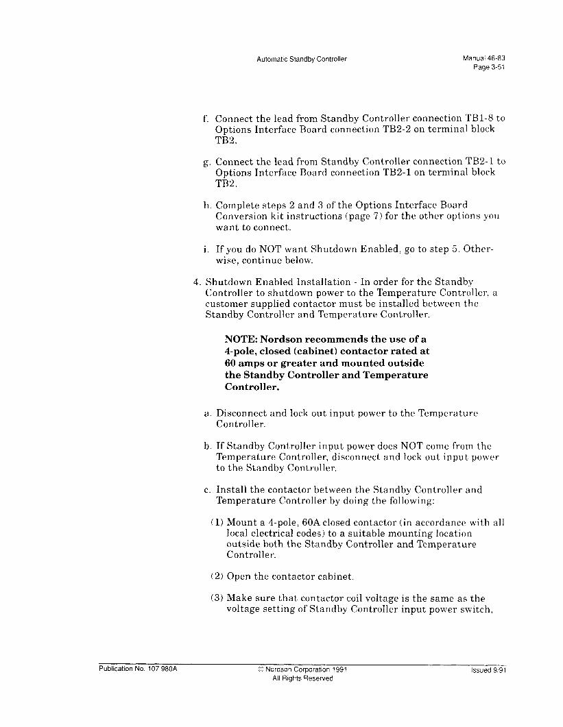
Automattc Standby Controller Manual 46-83 Page 3-51
f. Connect the lead from Standby Controller connection TBl-8 to Options Interface Board connection TB2-2 on terminal block TB2.
g. Connect the lead from Standby Controller connection TB2- 1 to Options Interface Board connection TB2-1 on terminal block TB2.
h. Complete steps 2 and 3 of the Options Interface Board Conversion kit instructions (page 7) for the other options you want to connect.
i. If you do NOT want Shutdown Enabled, go to step 5. Other- wise, continue below.
4. Shutdown Enabled Installation - In order for the Standby Controller to shutdown power to the Temperature Controller, a customer supplied contactor must be installed between the Standby Controller and Temperature Controller.
NOTE: Nordson recommends the use of a 4-pole, closed (cabinet) contactor rated at 60 amps or greater and mounted outside the Standby Controller and Temperature Controller.
a. Disconnect and lock out input power to the Temperature Controller.
b. If Standby Controller input power does NOT come from the Temperature Controller, disconnect and lock out input power to the Standby Controller.
c. Install the contactor between the Standby Controller and Temperature Controller by doing the following:
(1) Mount a 4-pole, 60A closed contactor (in accordance with all local electrical codes) to a suitable mounting location outside both the Standby Controller and Temperature Controller.
(2) Open the contactor cabinet.
(3) Make sure that contactor coil voltage is the same as the voltage setting of Standby Controller input power switch,
Publication No. 107 980A 0 Nordson Corporation 1991 All Rights Reserved
Issued 9191

Manual 46-83 Page 3-52
Automatic Standby Controller
S4 (see Figure 3.2). Otherwise, equipment damage can occur.
NOTE: If connecting the contactor to a single-phase Temperature Controller, use three-wire power cables to connect to input power and the Temperature Controller. If connecting the contactor to a three-phase Temperature Controller, use four-wire power cables to connect to input power and the Temperature Controller.
NOTE: Refer to Figure 3.17 for the location of all contactor to Standby Controller wiring connection points discussed below.
(4) Connect the leads of a three- or four-wire power cable (customer supplied) to the load side of the contactor. These wires must be the standard size as required for typical Temperature Controller power hook ups.
(5) Route the opposite end of the contactor load side cable through the Temperature Controller cord access hole to Temperature Controller terminal block TB 1.
(6) Connect th e contactor load side leads to Temperature Controller input connections ILl, L2 and/or L3, and N. These wires must also be the standard size as required for typical Temperature Controller power hook ups.
(7) Connect one side of the contactor coil to Controller connec- tion TB2-4.
(8) Connect the other side of the contactor coil to Controller con- nection TB3-2.
(9) Connect a jumper wire between Controller connections TB3- 2 to TB2-5.
(10) Connect th e ea s o another three- or four-wire power cable 1 d f (customer supplied) to the live side connectors on the con- tactor. These wires must be the standard size as required for typical Temperature Controller power hook ups.
Issued 9/91 0 Nordson Corporation 1991 All Rights Reserved
Publication No. 107 980A

Automatic Standby Controller Manual 46-83 Page 3-53
- AUTOMATIC STANDBY
CONTROLLER
&r TBl Ll L2 L3 N
1.
-- l I
L
120 OR 240 VAC
- I I - I
i
I I
TEMPERATURE CONTROLLER
LINE VOLTAGE TO APPLICATOR
/ CONTACTOR 1 I
Figure 3.17 - Electrical Connections for Installing a Contactor Between the Standby Controller and Temperature Controller
Publication No. 107 980A 0 Nordson Corporation 1991 All Rights Reserved
Issued 9191

Manual 46-83 Page 3-54
Automatic Standby Controller
(11) Route the opposite end of the contactor line side cable to the input voltage source for the Temperature Controller.
Final Installation Steps
1. Set the Standby Controller operating conditions as detailed in Section 4.
2. Close the contactor cabinet.
3. Replace the Temperature Controller electrical cabinet enclosure and tighten the captive screw on top of the cabinet that secures it.
4. Close the Standby Controller cover and slide the cabinet lock brackets over the front panel lip. Tighten the two retaining screws.
5. Restore input power to the Temperature Controller.
6. If using a bulk melter or applicator with the Temperature Controller:
a. Restore input power to the bulk melter or applicator.
b. Follow the “DAILY START-UP PROCEDURE” in the unit’s technical manual to restore the unit to operation.
7. Restore input power to the Standby Controller.
8. Resume system operation.
Issued 9191 0 Nordson Corporation 1991 All Rights Reserved
Publication No. 107 980A

Automatic Standby Controller Manual 46-83 Page 4-1
SECTION 4 OPERATING INSTRUCTIONS
OPERATING MODES
The Controller enables operators to select one of two applicator operating modes:
l Full Power
l Auto Standby
Full Power Mode
The yellow “FULL POWER” LED (Fig. 4.1) on the Controller front panel will light when the Mode selection switch is set to Full Power. The Controller’s standby circuitry is bypassed, and hot melt material in the applicator or bulk melter remains at application temperature.
l0 01
FULL
POWER -
LED
MODE --L-
SWITCH
STANDBY
ON LED
0 Noniso,~.
AUTO STANDBY CONTROLLER
FULL - MODE --STANDBY POWER
-0 Od
STANDBY RESET SHUTDOWN
PART NO.
SERIAL NO.
FUSE RATING AT 23OV AT 115V
POWER REQD. WATTS 11 S/230 VAC SO/60 H2: 1 PHASE
u STANDBY LED
SHUTDOWN
/’ LED
- RESET
1 PUSHBUTTON
Figure 4.1 - Controller LED Locations.
Publication No. 107 980A 0 Nordson Corporation 1991 Issued 9/91 All Rights Reserved

Manual 46-83 Page 4-2
Automatic Standby Controller
Auto Standby Mode
The yellow “STANDBY” LED (Fig. 4.1) on the Controller front panel will light when the Mode selection switch is set to Standby. The Controller either automatically reduces hot melt temperature or provides switch closure which certain devices use to regulate input power to the heaters in one of two conditions.
Standby Condition - The red “STANDBY ON” LED (Fig. 4.1) on the Controller front panel will light as soon as the Controller enters Standby and will remain on during this condition. Standby begins when no gun triggering signal is received within an operator-specified time frame (5-60 minutes). The Controller either automatically reduces hot melt temperature or provides switch closure for devices equipped with Temperature Setback (standby) or Remote I/O.
Temperature setback or the Remote I/O activates the temperature setback option in the bulk melter or applicator. Temperature setback reduces input power to either the device heating channels or the platen heating channel. The hot melt temperature to be maintained in the standby condition is set by using the device’s temperature control system.
NOTE: Once the temperature setback or the Remote I/O activates the bulk melter or applicator temperature setblack system, the hot melt material must be re!-heated to the application temperature. Do not attempt bulk melter or applicator operation until all temperatures are at application levels. Refer to your bulk melter or applicator technical manual for information regard- ing the applicator’s low temperature adjustments and the steps necessary for returning the bulk melter or applicator to application temperature settings.
The Controller remains in the Standby condition indefinitely until either:
l The Controller is manually switched to the Full Power mode (see above>, or
l The Reset push button is pressed, or
Issued 9/9 1 0 Nordson Corporation 1991 All Rights Reserved
Publication No. 107 980A

Automatic Standby Controller Manual 46-83 Page 4-3
l The Controller Shutdown circuit is enabled.
Reset - If the Reset push button (Figure 4.1) is pressed, the Controller exits the Auto Standby mode and temporarily enters the Full Power mode. After the first gun trigger signal, the Controller re-enters the Auto Standby mode.
Shutdown Condition (Shutdown Enabled) - The red “SHUT- DOWN ON” LED (Fig. 4.1) on the Controller front panel will light as soon as the Controller enters Shutdown and will remain on during this condition. If the Controller is not reset by the end of the standby condition time frame (with the Controller Shutdown Enabled switch ON), one of the following will occur:
1. If a 60A closed contactor is wired between the Controller and the device, the Controller will shut down power to the device.
2. If the device is equipped with standby capability, the Controller will provide switch closure which can use to start system shut- down (sleep for 3000-series applicators).
2. The Controller provides switch closure which can be used to remotely activate an alarm connection, status indicator, programmable controller, or other device.
Publication No. 107 980A 0 Nordson Corporation 1991 All Rights Reserved
Issued 9191

Manual 46-83 Page 4-4
Automatic Standby Controller
SETTING CONTROLLER CONDITIONS
A WARNING: The Controller contains energized
51 electrical components with potentials that can cause death. Disconnect and lock out input power to the Controller, and flip the Controller circuit breaker to the OFF position before proceeding. Avoid touching any energized Controller components.
The Standby and Shutdown potentiometers (“pots”), and the Shut- down Enable switch are located on the printed circuit board mounted inside the Controller cabinet. They are shown in Figure 4.2.
Standby Minutes Pot (Pl) - The time range for this pot is 5-60 minutes. The “TRIG” LED (Dl) will light each time a gun trigger signal is received. If the timer trips because there are no trigger signals, the Controller goes into the Standby condition. When the Controller is in the Standby condition, the “TRIG” LED does not light.
Shutdown Hours Pot (P2) - The time range for this pot is l-8 hours. The start of this time frame begins as soon as the Control- ler goes into the Standby condition.
Enable (Switch Sl) - When this slide switch is in the ON position, a relay will activate at the end of the “Shutdown Hours” period. The contacts on this relay can be used in various ways:
1) To shut off input power to the device if a 60A contactor is installed).
2) To activate the device’s shutdown or sleep mode, if it has them.
3) To activate an alarm, ler, or other device.
status in dicator, progra mmable control-
TRIG - This LED illuminates whenever a trigger signal is received, except when the Controller is in the Standby condition (when trigger signals are not recognized).
Issued 9/91 0 Nordson Corporation 1991 All Rights Reserved
Publication No. 107 980A

Automatic Standby Controller Manual 46-83 Page 4-5
33 4.3
n n Sl
Figure 4.2 - Controller Pot Locations.
Publication No. 107 980A 0 Nordson Corporataon 1991 All Rights Reserved
Issued 9191

Manual 46-83 Page 4-6
Automatic Standby Controller
This Page Intentionally Left Blank
Issued 9/91 0 Nordson Corporation 1991 All Rights Reserved
Publication No. 107 980A

Automatic Standby Controller Manual 46-83 Page 5-l
SECTION 5 TROUBLESHOOTING
INTRODUCTION
In this section, you will find the following fault isolation and correction procedures:
l Mode LEDs Not Lighting
l Standby LED Not Lighting (when Auto Standby mode selected)
l Shutdown ON LED Not Lighting (when switch enabled)
Obvious causes of malfunction, such as broken wires, missing or loose fasteners, etc. should be noted during visual inspection and corrected immediately.
The Controller wiring diagram and schematic are located at the end of this section.
SAFETY DURING TROUBLESHOOTING
A
A
WARNING: Before performing the following troubleshooting procedures, thoroughly review SECTION 1, SAFETY SUMMARY, in this manual. Only qualified personnel are to perform the following procedures.
WARNING: It is imperative that personnel operat- ing, maintaining, or troubleshooting the Standby Controller refer to the technical manuals for the bulk melter, applicator, and/or Temperature Control- ler and its associated equipment. The manuals pro- vide important s’afety, operation, and troubleshooting information used in conjunction with procedures presented in this manual.
WARNING: The Controller contains electrical poten- tials that can cause death. Use extreme caution when making adjustments to the Controller with the power ON. Only qualified personnel should make such adjustments.
Publication No. 107 980A 0 Nordson Corporation 1991 All Rights Reserved
Issued 9191

Automatic Standby Controller Manual 46-83 Page 5-2
Mode LEDs Not Lighting
1. Check for correct input voltage (120 VAC or 240 VAC).
2. Ensure that the voltage setting of switch S4 (Fig. 5.1) matches input voltage to the Controller.
Set switch S4 to proper voltage
3. Check continuity of both panel! fuses (item 9, Fig. 6.1). 1
4. Check continuity of printed cir- cuit board fuse (Figure 5.1). 1
Issued 9/91 0 Nordson Corporation 1991 All Rights Reserved
Publication No. 107 980A

Automatic Standby Controller Manual 46-83 Page 5-3
Mode LEDs Not Lighting (Continued)
Continuity? <_1 > AY!E!!+
YES
5. Check continuity of wiring be- tween input terminal block, fuses, and printed circuit board connector, XT (Fig. 5.1).
i
Replace defective fuse and re- store system to normal opera- tion.
6. Replace printed circuit board.
Publication No. 107 980A 0 Nordson Corporation 1991 All Rights Reserved
Issued 9191

Automatic Standby Controller Manual 46-83 Page 5-4
“Standby On” LED Not Lighting
1. Check for valid trigger input to printed circuit board. Unless Controller is in Standby mode, “TRIG” LED, DSl (Fig. 5.1), should light whenever gun trig- ger is pressed.
)-.!E YES
2. Check that pot Pl (Fig. 5.1) is, not set too high.
Check (and repair, if necessary) the trigger and connecting leads.
3. Replace printed circuit board.
Issued 9191 0 Nordson Corporation 1991 All Rights Reserved
Publication No. 107 980A

Automatic Standby Controller Manual 46-83 Page 5-5
“Shutdown ON” LED Not Lighting
NO >------
*
I 3. Replace printed circuit board. I
Set correctly and restore sys- tem to normal operation.
I 1
Publication No. 107 980A 0 Nordson Corporation 1991 All Rights Reserved
Issued 9’91

Manual 46-83 Page 5-6
Automatic Standby Controller
TRIG (‘;,,,T)
REMOTE RESET
% NO] XT 0 1.1
STANDBY
REMOTE STANDBY
CONTACT AATINO: 2A 0 28VDC
s ND) 1/2A 2 1ZovAc
3 lc 1 SHUTDOWN
REMOTE SHUTDOWN
Figure 5.1 - Controller Printed Circuit Board.
-FUSE
Issued 9191 0 Nordson Corporation 1991 All Rights Reserved
Publication No. 107 980A

Automatic Standby Controller Manual 46-83 Page 5-7
This Page Intentionally Left Blank
Publication No. 107 980A 0 Nordson Corporation 1991 All Rights Reserved
Issued 9191

Manual 46-83 Page 5-8
Automatic Standby Controller
HEAT Z&RINK TUBING OVER SOLDER JOINT (13) PLC’S. REF.
/
I -I sa STANDBY 0,
MODE
LT3
1 s2 RED /
SHUL\oWN BLK RED
LT4 N
-I r-
&1/‘;1
CABLE MOUNTS TO BE PLACED ON DOOR (2) PLC’S. REF.
LID
REAR VIEW
Figure 5.2 - Controller Electrical Wiring Diagram (1 of 2).
Issued 9191 0 Nordson Corporation 1991 All Rights Reserved
Publication No. 107 980A

Automatic Standby Controller Manual 46-83 Page 5-9
0 1
MOUNTS TO BE PLACED
ON ENCLOSURE WALL.
CABLE MOUNTS TO BE PLACED ON ENCLOSURE WALL (3) PLC’S. REF.
Figure 5.2 - Controller Electrical Wiring Diagram (2 of 2).
Publication No. 107 980A 0 Nordson Corporation 1991 All Rights Reserved
Issued 9/91

Manual 46-83 Page 5-10
Automatic Standby Controller
F2 & F3 AJ?E f?ATED AT 32~~ FOR 230 VAC INPUT, AHD 63kA4 FOR 115V INPUl.
UNUSt D GATES
Ul r-
10
6
i::
11 CD401 38
9
Figure 5.3 - Controller Electrical Schematic (1 of 2).
Issued 9/91 0 Nordson Corporation 1991 All Rights Reserved
Publication No. 107 980A

Automatic Standby Controller Manual 46-83 Page 5-l 1
LOCATED OFF PCB
STANDBY em- 1\ TIME TEST $130 1%
TEST FIXTURE
ON I 1
SHUTCXMN OUTPUT
CONNECTION
REMOTE SHCmXmN
OUTPUT 01 ’ CONNECTION
A.
7--
Rl2 10K
i 4 2N7000 ~
i
Figure 5.3 - Controller Electrical Schematic (2 of 2).
Publication No. 107 980A 0 Nordson Corporation 1991 All Rights Reserved
Issued 919 1

Manual 46-83 Page 5-12
Automatic Standby Controller
This Page Intentionally Left Blank
Issued 9/91 0 Nordson Corporation 1991 All Rights Reserved
Publlcatlon No. 107 980A

Automatic Standby Controller Manual 46-83 Page 6- 1
SECTION 6 PARTS LISTS
INTRODUCTION
This section contains the illustrated parts list for the Controller.
Using the Illustrated Parts List
1. Look in the parts list to find the part or parts you need to identify.
2. Study the illustrations to find the specific part(s) you want identified.
3. Locate the item number of the part in the Item Number column.
4. The next three columns provide:
l the Nordson Part Number. A dash indicates that the item is a nonsaleable part or subassembly of a saleable assembly.
l the part’s Description. The part’s name, dimension’s and the physical properties are provided. Bullets indicate the level of assembly of the part. A part preceded by one bullet (0) is a component of the assembly above it. A part whose description is preceded by two bullets (0 0) is a component of the item above it whose description is preceded by only one bullet.
l the Req’d column indicates the quantity requirements pel unit or assembly. If the item is listed for reference only, “Ref” or a dash appears in the column. The dash is used for items that exist in the illustrated assembly, but in a nonquantitative form.
Publication No. 107 980A 0 Nordson Corporation 1991 All Rights Reserved
issued 9191

Manual 46-83 Page 6-2
Automatic Standby Controller
-0 2
D 4
-0 5
(3) 1 II I I II I I II #I I STANDBY RESET SHUTDOWN
ON ON LIP’”
GND
8 P
/- SEE DETAIL A
3 -6
Figure 6.1 - Automatic Standby Controller Parts Illustration
Issued 9/91 0 Nordson Corporation 1991 All Rights Reserved
Publication No. 107 980A

Table 6.1 - Automatic Standby Controller Parts List -.- --- ___ -___ -__ Item Part
Number Number - l-05 827
1 105823
2 101 780
3 807 293
4 101 783
5 985101
6 101 784
7
8
9
10
11
12
13
14
15
16
17
18
19
20
21
22
101 782
105825
933477
105807
105 809
900 757
981 729
240674
933476
983 120
984129
-
242 654
242 687
981 247
-
-
-
-
107 980
242837
939110
Automatic Standby Controller
Description _-- Controller, Automatic Standby
l
0
l
0
l
l
l
l
l
0
l
l
l
l
l
l
l
l
l
Enclosure, Painted
Name Plate
Switch, 2-Position, DPDT (MODE)
Light, Yellow (FULL POWER & STANDBY)
Rivet, Pop
Light, Red (STANDBY ON & SHUTDOWN
ON) Pushbutton, Reset
Panel, w/Hardware
Holder, Fuse
Fuse, 32 mA
Fuse, 63 mA
Plug, Cap
Screw, Pan-Head, #I O-32
Tag, Ground
Lug, Terminal, 45’
Washer, Lock, ##IO
Nut, Hex, Brass, #lo-32
Wire Harness
Gasket, Cabinet
Latch, Cabinet
Screw, Fillister Head, l/4-28 x 5/ 8 in.
Tag, Warning, Disconnect Power
Manual
Mount, Cable Strap
Straw. Cable
Manual 46-83 Page 6-3
Req’d
Ref
1
1
1
2
8
2
1
1
2
1
1
3
4
2
2
2
2
1
2.5 ft.
2
2
1
1
5
5
Publication No. 107 980A 0 Nordson Corporation 1991 All Rights Reserved
Issued 9’91

Manual 46-83 Page 6-4
Automatic Standby Controller
This Page Intentionally Left Blank
Issued 9/91 0 Nordson Corporation 1991 All Rights Reserved
Pubkatlon No 107 980A

Automatic Standby Controller Manual 46-83 Page 7-l
SECTION 7 TECHNICAL DATA
AUTOMATIC STANDBY CONTROLLER SPECIFICATIONS
Electrical Requirements . . . . . . . . . . . . . . . . . . . . . . . . . . . . . 115 VAC, 50/60 Hz, 65 mA 230 VAC, 50/60 Hz, 32 mA
Dimensions . . . . . . . . . . . . . . . . . . . . . . . . . . . . . . . . . . . . . . . . . . . . . . Height - 10.5 inches (26.7 cm) Width - 8.5 inches ( 21.6 cm) Depth - 4.5 inches (11.4 cm)
Operating Environment . . . . . . . . . . . . . . . . . . . . . . . . . . . . . . . . 20” to 120°F (-7” to 49’ C) 0% to 90% Relative Humidity,
Noncondensing
Inputs . . . . . . . . . . . . . . . . . . . . . . . . . . . . . . . . . . . . . ..I....... 24 VDC or 120 VAC trigger signal from gun; Contact closure for
remote reset
outputs . . . . . . . . . . . . . . . . . . . . . . . . . . . . . . . . . . . . . . . . . . . . . . . . . . Two (2) sets of form C contacts for standby condition; Two (2) sets
of form C contacts for shutdown condition; all contacts rated at
2A@ 28VDC,0.5A8120VAC)
NOTE: Due to possible technological and/or quality improvements, equipment specifi- cations are subject to change without notice.
Publication No. 107 980A 0 Nordson Corporation 1991 All Rights Reserved
Issued 9/91

Manual 46-83 Page 7-2
Automatic Standby Controller
This Page Intentionally Left Blank
Issued 9191 0 Nordson Corporation 1991 All Rights Reserved
Publication No. 107 980A